KR20150132311A - Article of footwear comprising a sole structure including a billows structure - Google Patents
Article of footwear comprising a sole structure including a billows structureDownload PDFInfo
- Publication number
- KR20150132311A KR20150132311AKR1020157028639AKR20157028639AKR20150132311AKR 20150132311 AKR20150132311 AKR 20150132311AKR 1020157028639 AKR1020157028639 AKR 1020157028639AKR 20157028639 AKR20157028639 AKR 20157028639AKR 20150132311 AKR20150132311 AKR 20150132311A
- Authority
- KR
- South Korea
- Prior art keywords
- corrugated
- sole structure
- region
- foam member
- component
- Prior art date
- Legal status (The legal status is an assumption and is not a legal conclusion. Google has not performed a legal analysis and makes no representation as to the accuracy of the status listed.)
- Ceased
Links
- 239000006260foamSubstances0.000claimsabstractdescription180
- 229920000642polymerPolymers0.000claimsabstractdescription90
- 210000002683footAnatomy0.000claimsabstractdescription61
- 210000004744fore-footAnatomy0.000claimsabstractdescription53
- 210000000452mid-footAnatomy0.000claimsabstractdescription20
- 239000006261foam materialSubstances0.000claimsdescription54
- 238000000034methodMethods0.000claimsdescription28
- 239000000306componentSubstances0.000description346
- 230000001681protective effectEffects0.000description124
- 210000000474heelAnatomy0.000description116
- 239000000463materialSubstances0.000description58
- 210000003371toeAnatomy0.000description21
- 239000000853adhesiveSubstances0.000description13
- 230000001070adhesive effectEffects0.000description13
- 239000004568cementSubstances0.000description12
- 238000010276constructionMethods0.000description11
- 210000001872metatarsal boneAnatomy0.000description11
- 238000013016dampingMethods0.000description9
- 238000005299abrasionMethods0.000description8
- 239000004433Thermoplastic polyurethaneSubstances0.000description7
- 239000011162core materialSubstances0.000description7
- 229920001971elastomerPolymers0.000description7
- 239000005060rubberSubstances0.000description7
- 229920002803thermoplastic polyurethanePolymers0.000description7
- 230000008878couplingEffects0.000description6
- 238000010168coupling processMethods0.000description6
- 238000005859coupling reactionMethods0.000description6
- 238000005520cutting processMethods0.000description6
- 239000005038ethylene vinyl acetateSubstances0.000description5
- 210000001255halluxAnatomy0.000description5
- 238000004519manufacturing processMethods0.000description5
- 229920001200poly(ethylene-vinyl acetate)Polymers0.000description5
- 210000003423ankleAnatomy0.000description4
- 238000005452bendingMethods0.000description4
- 230000015572biosynthetic processEffects0.000description4
- 150000001875compoundsChemical class0.000description4
- 230000000694effectsEffects0.000description4
- 239000004744fabricSubstances0.000description4
- 239000002861polymer materialSubstances0.000description4
- 230000008569processEffects0.000description4
- 229920003051synthetic elastomerPolymers0.000description4
- 239000005061synthetic rubberSubstances0.000description4
- 229920005830Polyurethane FoamPolymers0.000description3
- 230000008859changeEffects0.000description3
- 239000000835fiberSubstances0.000description3
- 239000012530fluidSubstances0.000description3
- 239000000203mixtureSubstances0.000description3
- 230000004048modificationEffects0.000description3
- 238000012986modificationMethods0.000description3
- 238000000465mouldingMethods0.000description3
- 229920003023plasticPolymers0.000description3
- 239000004033plasticSubstances0.000description3
- 239000011496polyurethane foamSubstances0.000description3
- 238000009958sewingMethods0.000description3
- 230000007704transitionEffects0.000description3
- 229920002614Polyether block amidePolymers0.000description2
- 238000000429assemblyMethods0.000description2
- 230000000386athletic effectEffects0.000description2
- 230000008901benefitEffects0.000description2
- 238000006243chemical reactionMethods0.000description2
- 239000002131composite materialSubstances0.000description2
- BFMKFCLXZSUVPI-UHFFFAOYSA-Nethyl but-3-enoateChemical compoundCCOC(=O)CC=CBFMKFCLXZSUVPI-UHFFFAOYSA-N0.000description2
- 239000012943hotmeltSubstances0.000description2
- 238000009940knittingMethods0.000description2
- 239000010985leatherSubstances0.000description2
- 239000011159matrix materialSubstances0.000description2
- 239000007787solidSubstances0.000description2
- 229920000089Cyclic olefin copolymerPolymers0.000description1
- 229920002430Fibre-reinforced plasticPolymers0.000description1
- 239000004677NylonSubstances0.000description1
- 239000004698PolyethyleneSubstances0.000description1
- 239000000654additiveSubstances0.000description1
- 230000000996additive effectEffects0.000description1
- 238000003491arrayMethods0.000description1
- DQXBYHZEEUGOBF-UHFFFAOYSA-Nbut-3-enoic acid;etheneChemical compoundC=C.OC(=O)CC=CDQXBYHZEEUGOBF-UHFFFAOYSA-N0.000description1
- 210000000459calcaneusAnatomy0.000description1
- 239000004918carbon fiber reinforced polymerSubstances0.000description1
- 239000012876carrier materialSubstances0.000description1
- 230000006835compressionEffects0.000description1
- 238000007906compressionMethods0.000description1
- 239000000470constituentSubstances0.000description1
- 238000001816coolingMethods0.000description1
- 229920001577copolymerPolymers0.000description1
- 239000008358core componentSubstances0.000description1
- 230000003247decreasing effectEffects0.000description1
- 210000003195fasciaAnatomy0.000description1
- 239000002657fibrous materialSubstances0.000description1
- 238000009408flooringMethods0.000description1
- 230000004927fusionEffects0.000description1
- 238000007526fusion splicingMethods0.000description1
- 230000005021gaitEffects0.000description1
- 239000003365glass fiberSubstances0.000description1
- 238000005984hydrogenation reactionMethods0.000description1
- 238000005304joiningMethods0.000description1
- 239000002649leather substituteSubstances0.000description1
- 239000004620low density foamSubstances0.000description1
- 230000013011matingEffects0.000description1
- ORQBXQOJMQIAOY-UHFFFAOYSA-NnobeliumChemical compound[No]ORQBXQOJMQIAOY-UHFFFAOYSA-N0.000description1
- 229920001778nylonPolymers0.000description1
- 230000002093peripheral effectEffects0.000description1
- -1polyethylenePolymers0.000description1
- 229920000573polyethylenePolymers0.000description1
- 230000009257reactivityEffects0.000description1
- 230000009467reductionEffects0.000description1
- 238000005096rolling processMethods0.000description1
- 239000000758substrateSubstances0.000description1
- 210000004243sweatAnatomy0.000description1
- 229920001169thermoplasticPolymers0.000description1
- 239000004416thermosoftening plasticSubstances0.000description1
- 210000001364upper extremityAnatomy0.000description1
- 238000009423ventilationMethods0.000description1
- 239000011800void materialSubstances0.000description1
- 239000004711α-olefinSubstances0.000description1
Images


Classifications
- A—HUMAN NECESSITIES
- A43—FOOTWEAR
- A43B—CHARACTERISTIC FEATURES OF FOOTWEAR; PARTS OF FOOTWEAR
- A43B1/00—Footwear characterised by the material
- A43B1/0018—Footwear characterised by the material made at least partially of flexible, bellow-like shaped material
- A—HUMAN NECESSITIES
- A43—FOOTWEAR
- A43B—CHARACTERISTIC FEATURES OF FOOTWEAR; PARTS OF FOOTWEAR
- A43B13/00—Soles; Sole-and-heel integral units
- A43B13/02—Soles; Sole-and-heel integral units characterised by the material
- A—HUMAN NECESSITIES
- A43—FOOTWEAR
- A43B—CHARACTERISTIC FEATURES OF FOOTWEAR; PARTS OF FOOTWEAR
- A43B13/00—Soles; Sole-and-heel integral units
- A43B13/02—Soles; Sole-and-heel integral units characterised by the material
- A43B13/04—Plastics, rubber or vulcanised fibre
- A—HUMAN NECESSITIES
- A43—FOOTWEAR
- A43B—CHARACTERISTIC FEATURES OF FOOTWEAR; PARTS OF FOOTWEAR
- A43B13/00—Soles; Sole-and-heel integral units
- A43B13/02—Soles; Sole-and-heel integral units characterised by the material
- A43B13/12—Soles with several layers of different materials
- A43B13/125—Soles with several layers of different materials characterised by the midsole or middle layer
- A—HUMAN NECESSITIES
- A43—FOOTWEAR
- A43B—CHARACTERISTIC FEATURES OF FOOTWEAR; PARTS OF FOOTWEAR
- A43B13/00—Soles; Sole-and-heel integral units
- A43B13/14—Soles; Sole-and-heel integral units characterised by the constructive form
- A43B13/18—Resilient soles
- A43B13/181—Resiliency achieved by the structure of the sole
- A43B13/186—Differential cushioning region, e.g. cushioning located under the ball of the foot
- A—HUMAN NECESSITIES
- A43—FOOTWEAR
- A43B—CHARACTERISTIC FEATURES OF FOOTWEAR; PARTS OF FOOTWEAR
- A43B13/00—Soles; Sole-and-heel integral units
- A43B13/14—Soles; Sole-and-heel integral units characterised by the constructive form
- A43B13/18—Resilient soles
- A43B13/187—Resiliency achieved by the features of the material, e.g. foam, non liquid materials
- A—HUMAN NECESSITIES
- A43—FOOTWEAR
- A43B—CHARACTERISTIC FEATURES OF FOOTWEAR; PARTS OF FOOTWEAR
- A43B13/00—Soles; Sole-and-heel integral units
- A43B13/14—Soles; Sole-and-heel integral units characterised by the constructive form
- A43B13/22—Soles made slip-preventing or wear-resisting, e.g. by impregnation or spreading a wear-resisting layer
- A43B13/223—Profiled soles
- A—HUMAN NECESSITIES
- A43—FOOTWEAR
- A43B—CHARACTERISTIC FEATURES OF FOOTWEAR; PARTS OF FOOTWEAR
- A43B3/00—Footwear characterised by the shape or the use
- A43B3/0036—Footwear characterised by the shape or the use characterised by a special shape or design
- A43B3/0042—Footwear characterised by the shape or the use characterised by a special shape or design with circular or circle shaped parts
Landscapes
- Chemical & Material Sciences (AREA)
- Engineering & Computer Science (AREA)
- Materials Engineering (AREA)
- Footwear And Its Accessory, Manufacturing Method And Apparatuses (AREA)
Abstract
Translated fromKorean
Description
Translated fromKorean관련 출원 데이터Related Application Data
본 출원은, (a) 2013년 3월 15일자로 출원되고 명칭이 "보호 요소를 갖는 경량의 중창 부재를 구비하는 밑창 구조체 및 신발류 물품(Sole Structures and Articles of Footwear Having a Lightweight Midsole Member with Protective Elements)"인 미국 특허 출원 제13/835,715호; (b) 2013년 3월 15일자로 출원되고 명칭이 "보호 요소를 갖는 경량의 중창 부재를 구비하는 밑창 구조체 및 신발류 물품(Sole Structures and Articles of Footwear Having a Lightweight Midsole Member with Protective Elements)"인 미국 특허 출원 제13/838,051호; 및 (c) 2013년 3월 15일자로 출원되고 명칭이 "보호 요소를 갖는 경량의 중창 부재를 구비하는 밑창 구조체 및 신발류 물품(Sole Structures and Articles of Footwear Having a Lightweight Midsole Member with Protective Elements)"인 미국 특허 출원 제13/837,967호에 대한 우선권을 주장한다. 이들 우선권 출원 각각은 그 전체가 본 명세서에 참조로 합체된다.(A) a sole structure and footwear article having a lightweight midsole member having a protective element, filed on March 15, 2013 and having the name < RTI ID = 0.0 > U.S. Patent Application No. 13 / 835,715; (b) the United States of America, which was filed on March 15, 2013 and is entitled "Sole Structures and Footwear Having a Lightweight Midsole Member with Protective Elements" Patent Application No. 13 / 838,051; And (c) a sole structure and footwear article having a lightweight midsole member having a protective element, filed on March 15, 2013, entitled " Sole Structures and Footwear Having a Lightweight Midsole Member with Protective Elements & U.S. Patent Application No. 13 / 837,967. Each of these priority applications is incorporated herein by reference in its entirety.
발명의 분야Field of invention
본 발명은 신발류(footwear)의 분야에 관한 것이다. 보다 상세하게는, 본 발명의 태양은 보호 구성요소에 의해 부분적으로 덮인 비교적 연질 및/또는 경량의 폼 중창 구성요소(foam midsole component)를 포함하는 밑창 구조체(sole structure) 및/또는 신발류(예를 들면, 운동화류) 물품에 관한 것이다.The present invention relates to the field of footwear. More particularly, aspects of the present invention provide a sole structure comprising a relatively soft and / or lightweight foam midsole component partially covered by a protective component and / For example, running shoes).
통상의 운동화류 물품은 2개의 주 요소, 즉 갑피(upper)와 밑창 구조체를 포함한다. 갑피는 밑창 구조체에 대해 발을 안정적으로 수용하여 배치하는 발을 위한 커버를 제공한다. 또한, 갑피는 발을 보호하고 통기를 제공하는 구성을 가지고, 이에 의해 발을 냉각시키고 땀을 제거한다. 밑창 구조체는 갑피의 하측면에 고정되고, 일반적으로 발과 임의의 접촉면 사이에 배치된다. 지면 반력을 감쇠하고 에너지를 흡수하는 것에 부가하여, 밑창 구조체는 트랙션(traction)을 제공하고, 과회내(overpronation)와 같은 잠재적으로 유해한 발 운동을 제어할 수 있다. 갑피 및 밑창 구조체의 일반적인 특징 및 구성이 하기에서 보다 상세하게 설명된다.A typical running shoes article includes two main elements, an upper and a sole structure. The upper provides a cover for the foot that stably receives and places the foot against the sole structure. In addition, the upper has a configuration that protects the foot and provides ventilation, thereby cooling the foot and removing sweat. The sole structure is fixed to the lower side of the upper, and is generally disposed between the foot and any contact surface. In addition to attenuating ground reaction forces and absorbing energy, the sole structure provides traction and can control potentially harmful foot movements such as overpronation. The general features and construction of the upper and sole structures are described in more detail below.
갑피는 발을 수용하기 위한 공동(void)을 신발류의 내부에 형성한다. 공동은 대체로 발의 형상을 가지며, 공동에의 접근은 발목 개구부(ankle opening)에서 제공된다. 따라서, 갑피는 발의 발등 및 발가락 영역 위로, 발의 안쪽 및 바깥쪽 측부를 따라, 발의 힐(heel) 영역 주위로 연장된다. 끈 시스템(lacing system)은 흔히 갑피에 합체되어 발목 개구부의 크기를 선택적으로 변경하고 착용자가 갑피의 특정 치수, 특히 거스(girth)를 변경하게 하여 다양한 크기를 갖는 발을 수용하도록 한다. 또한, 갑피는 신발류의 편안함을 향상시키기 위해(예를 들면, 끈에 의해 발에 가해지는 압력을 조절하기 위해) 끈 시스템 아래에서 연장되는 텅(tongue)을 포함할 수 있고, 갑피는 또한 힐의 이동을 제한 또는 제어하는 힐 카운터(heel counter)를 포함할 수도 있다.The upper forms a void inside the footwear for receiving the feet. The cavity generally has a foot shape, and access to the cavity is provided at the ankle opening. Thus, the upper extends along the foot and the toe area of the foot, along the inner and outer sides of the foot, and around the heel area of the foot. The lacing system is often incorporated into the upper so that the size of the ankle opening is selectively changed and the wearer is allowed to vary the specific dimensions of the upper, especially the girth, to accommodate the feet of various sizes. The upper may also include a tongue extending under the strap system to improve the comfort of the footwear (e.g., to adjust the pressure applied to the foot by the strap), and the upper may also include a tongue And a heel counter for limiting or controlling movement.
일반적으로, 밑창 구조체는, 전통적으로 "안창(insole)", "중창(midsole)" 및 "바닥창(outsole)"으로 불리는 다중층을 포함한다. 안창(또한 깔창(sock liner)을 구성할 수도 있음)은 신발류의 편안함을 향상시키기 위해, 예를 들어 수분을 빨아들여 부드럽고 편안한 느낌을 제공하기 위해 갑피 내에서 발바닥(하측) 표면에 인접하여 위치된 얇은 부재이다. 전통적으로 갑피의 전체 길이를 따라 갑피에 부착되는 중창은 밑창 구조체의 중간층을 형성하고, 발 운동 제어 및 충격력 감쇠를 포함하는 다양한 목적에 도움을 준다. 바닥창은 신발류의 지면-접촉 요소를 형성하고, 통상 트랙션을 향상시키는 텍스처링(texturing) 및 다른 특징부를 포함하는 내구성 및 내마모성 재료로 만들어진다.Generally, the sole structure includes multiple layers traditionally referred to as "insole", "midsole" and "outsole". An insole (which may also comprise a sock liner) may be positioned adjacent to the sole (lower) surface within the upper to enhance the comfort of the footwear, e.g., to provide a soft, It is a thin member. Traditionally, the midsole attached to the upper along the entire length of the upper part forms an intermediate layer of the sole structure and serves a variety of purposes, including foot motion control and impact damping. The floor window is made of a durable and wear resistant material that includes texturing and other features that form the ground-contacting elements of the footwear and which normally enhance traction.
통상의 중창의 주 요소는 신발류의 길이 전체에 걸쳐서 연장되는 폴리우레탄 폼 또는 에틸비닐아세테이트(ethylvinylacetate; "EVA")와 같은 탄성의 폴리머 폼 재료이다. 중창에서의 폴리머 폼 재료의 특성은, 주로 중창의 치수 구성과, 폴리머 폼 재료의 밀도 및/또는 경도를 포함하여, 폴리머 폼에 대해 선택된 재료의 특정 특성을 포함하는 요인에 따라 달라진다. 중창 전체에 걸쳐서 이들 요인을 변경함으로써, 상대 강성, 지면 반력 감쇠의 정도 및 에너지 흡수 특성은 신발류가 사용되도록 의도된 활동의 특정 요구를 충족시키도록 변경될 수 있다.The main element of a typical midsole is an elastic polymer foam material, such as polyurethane foam or ethylvinylacetate ("EVA"), which extends throughout the length of the footwear. The properties of the polymer foam material in the midsole will depend primarily on the dimensional configuration of the midsole and the factors including the specific properties of the material selected for the polymer foam, including the density and / or hardness of the polymer foam material. By varying these factors throughout the midsole, the relative stiffness, the degree of ground reaction force attenuation, and the energy absorbing characteristics can be altered to meet the specific needs of the activities for which footwear is intended to be used.
많은 이용가능 신발류 모델 및 특성에도 불구하고, 새로운 신발류 모델 및 구조는 계속 개발되고 있으며, 본 기술분야에 반가운 진보가 된다.Despite the many available footwear models and characteristics, new footwear models and structures continue to develop and are a welcome advance in the art.
본 요약은 상세한 설명에 있어서 하기에서 추가로 설명되는, 단순화된 형태의 본 발명에 관한 일부의 일반적인 개념을 도입하도록 제공된다. 본 요약은 본 발명의 주요 특징 또는 필수 특징을 식별하도록 의도되지 않는다.This summary is provided to introduce some general concepts of the invention in a simplified form that are further described below in the Detailed Description. This summary is not intended to identify key features or essential features of the invention.
임의의 원하는 타입 또는 스타일의 신발에 잠재적으로 유용하지만, 본 발명의 태양은 농구화, 런닝화, 크로스-트레이닝화(cross-training shoes), 미끄럼방지 신발(cleated shoes), 테니스화, 골프화 등을 포함하는 운동화류 물품에 사용되는 밑창 구조체에 특별한 흥미가 있을 수 있다.While potentially useful in any desired type or style of footwear, aspects of the present invention may be applied to shoes such as basketball shoes, running shoes, cross-training shoes, cleated shoes, tennis shoes, There may be special interest in the sole structure used for articles.
본 발명의 보다 구체적인 태양은 착용자 발의 적어도 힐 및 중족부(midfoot) 영역을 지지하기 위한 제1 폴리머 폼 부재를 포함하는 신발류 물품용 밑창 구조체에 관한 것이다. 이러한 제1 폴리머 폼 부재의 노출된 외측 에지는, 적어도 일부 예에서, 제1 폴리머 폼 부재의 안쪽 중족부 또는 전족부(forefoot) 영역으로부터, 후방 힐 영역 주위로 그리고 제1 폴리머 폼 부재의 바깥쪽 중족부 또는 전족부까지 연속적으로 연장되는 파형부 구조체(billows structure)를 포함한다. 예를 들어 인터위빙형 파형부(interwoven billow), 지지 리브(support rib) 등을 포함하는 다른 파형부 구조체는 본 발명의 적어도 일부의 예에서 제공될 수 있다. 이들 파형부 구조체는 인접한 파형부 외측 리지(billow outer redge) 사이에 위치된 파형부 개재 영역(billow interstitial area)에 의해 연결된 2개 내지 8개의 파형부 외측 리지를 포함할 수 있다.A more specific aspect of the invention relates to a sole structure for footwear articles comprising a first polymer foam member for supporting at least a heel and midfoot region of a wearer's foot. The exposed outer edge of such a first polymer foam member may, at least in some instances, extend from the inner forefoot region or forefoot region of the first polymer foam member to around the rear heel region and to the outside of the first polymer foam member, And a billows structure extending continuously to the forefoot or forefoot. For example, other corrugated sub-structures including interwoven billow, support ribs, etc. may be provided in at least some examples of the present invention. These corrugator structures may include two to eight corrugated lateral ridges connected by a billow interstitial area located between adjacent corrugated outer billings.
본 발명의 다른 예에 따른 밑창 구조체는 착용자 발의 적어도 힐 및 중족부 영역을 지지하기 위한 폴리머 폼 부재(선택적으로, 0.25g/㎤ 미만의 밀도를 갖는 폼 재료와 같은 경량의 저밀도 폴리머 폼 재료)를 포함할 수 있다. 이러한 폴리머 폼 부재의 노출된 외측 에지는,A sole structure according to another example of the present invention includes a polymer foam member (optionally, a lightweight low density polymer foam material such as a foam material having a density of less than 0.25 g / cm < 3 >) for supporting at least the heel and mid- . The exposed outer edge of such a polymer foam member,
(a) 제1 외측 파형부 리지, 제2 외측 파형부 리지, 제3 외측 파형부 리지, 제1 및 제2 외측 파형부 리지 사이에 위치된 제1 개재 영역, 및 제2 및 제3 외측 파형부 리지 사이에 위치된 제2 개재 영역을 포함하는 제1 파형부 구조체, 및(a) a first outer-corrugated bulge, a second outer-corrugated bulge, a third outer-corrugated bulge, a first intervening region positioned between the first and second outer-corrugated bulges, and a second and third outer- A first wave-portion-side structure including a second intervening region positioned between the first and second wave-
(b) 제4 외측 파형부 리지, 제5 외측 파형부 리지, 및 제4 및 제5 외측 파형부 리지 사이에 위치된 제3 개재 영역을 포함하는 제2 파형부 구조체를 포함할 수 있으며,(b) a third corrugated structure including a fourth outer corrugated bulge, a fifth outer corrugated bulge, and a third intervening region positioned between the fourth and fifth outer corrugated bulges,
제4 외측 파형부 리지는 제1 개재 영역에서 시작되고, 제5 외측 파형부 리지는 제2 개재 영역에서 시작된다. 폴리머 폼 부재의 노출된 외측 에지는 다른 파형부 구조체를 추가로 포함할 수 있으며, 예를 들어 그러한 파형부 구조체의 외측 파형부 리지는 제3 개재 영역에서 시작된다. 하나의 파형부 구조체는 밑창 구조체의 후방 힐 영역 주위로 연장될 수 있는 한편, 다른 파형부 구조체는 밑창 구조체의 측부 중족부 영역에 위치될 수 있다. 바닥창 구성요소는 폴리머 폼 부재의 바닥면과 결합될 수 있다.The fourth outer corrugated bulge starts in the first intervening area and the fifth outer corrugated bulge starts in the second intervening area. The exposed outer edge of the polymeric foam member may further comprise other corrugated sub-structures, for example the outer corrugated sub-ridges of such corrugated sub-structures start in the third interposed region. One corrugated subassembly may extend around the rear heel region of the sole structure while another corrugated side structure may be located in the side flank region of the sole structure. The bottom window component may engage the bottom surface of the polymer foam member.
본 발명의 일부 예에 따른 다른 밑창 구조체는 착용자 발의 적어도 힐 영역을 지지하기 위한 제1 폴리머 폼 부재를 포함하며, 이러한 제1 폴리머 폼 부재는, (a) 바깥쪽 측벽, (b) 안쪽 측벽, (c) 안쪽 측벽 및 바깥쪽 측벽을 연결하는 후방 힐 벽, (d) 안쪽 측벽, 바깥쪽 측벽 및 후방 힐 벽을 연결하는 바닥 벽, 및 (e) 후방 힐 벽에 대향하는 개방 단부를 갖는 외측 쉘(outer shell)을 구성하고, 이러한 제1 폴리머 폼 부재는 밑창 구조체의 후방 힐 영역 주위로 연장된다. 제2 폴리머 폼 부재는 제1 폴리머 폼 부재의 외측 쉘에 의해 형성된 공간에 적어도 부분적으로 수용되는 힐 부분을 구비하며, 제2 폴리머 폼 부재의 전족부 단부는 제1 폴리머 폼 부재의 개방 단부를 지나서 연장된다. 이러한 제2 폴리머 폼 부재는 제1 폴리머 폼 부재의 밀도보다 작은 밀도를 가지며, 제2 폴리머 폼 부재의 바닥면의 일부분은 신발류 물품의 바닥 전족부 영역에서 노출된다. 원한다면, 하나 이상의 보호 요소가 바닥 전족부 영역에서 제2 폴리머 폼 부재의 바닥면과 결합될 수 있다.Another outsole structure according to some embodiments of the present invention includes a first polymer foam member for supporting at least a heel region of a wearer's foot, the first polymer foam member comprising: (a) an outer sidewall, (b) (c) a rear heel wall connecting the inner side wall and the outer side wall, (d) a bottom wall connecting the inner side wall, the outer side wall and the rear heel wall, and (e) Constitutes an outer shell, and this first polymer foam member extends around the rear heel region of the sole structure. The second polymer foam member having a heel portion at least partially received in a space defined by the outer shell of the first polymer foam member and the forefoot end of the second polymer foam member extending beyond the open end of the first polymer foam member do. This second polymer foam member has a density less than the density of the first polymer foam member and a portion of the bottom surface of the second polymer foam member is exposed in the bottom forefoot region of the footwear article. If desired, one or more protective elements can be combined with the bottom surface of the second polymer foam member in the bottom forefoot region.
본 발명의 일부 예에 따른 또 다른 밑창 구조체는, (a) 착용자 발의 전체 발바닥 표면을 지지하기 위한 폴리머 폼 부재로서, 0.25g/㎤ 미만의 밀도를 갖는 폼 재료를 포함하는, 폴리머 폼 부재, 및 (b) 이 폴리머 폼 부재의 바닥면의 표면적의 적어도 80%를 덮도록 폴리머 폼 부재와 결합되는 보호 부재를 포함하며, 보호 부재는 웨브 베이스면(web base surface)을 구성하고, 복수의 트랙션 요소가 웨브 베이스면으로부터 하방으로 연장되고, 복수의 트랙션 요소들 사이의 위치에서의 대부분의 웨브 베이스면의 두께는 2㎜ 미만의 두께이다.Another shoe structure according to some embodiments of the present invention is a polymer foam member for supporting an entire sole surface of a wearer's foot, the polymer foam member comprising a foam material having a density of less than 0.25 g / cm < 3 & (b) at least 80% of the surface area of the bottom surface of the polymer foam member, wherein the protective member comprises a web base surface, and the plurality of traction elements Extends downwardly from the web base surface and the thickness of most web base surfaces at positions between the plurality of traction elements is less than 2 mm thick.
본 발명의 추가적인 태양은 갑피와 결합되는 전술한 다양한 타입의 밑창 구조체를 포함하는 신발류 물품에 관한 것이다. 본 발명의 또 다른 태양은 전술한(그리고, 하기에서 보다 상세하게 설명되는) 다양한 타입의 밑창 구조체 및/또는 신발류 물품을 제조하는 방법에 관한 것이다. 본 발명의 보다 구체적인 태양은 하기에서 보다 상세하게 설명될 것이다.A further aspect of the invention relates to an article of footwear comprising a sole structure of the various types described above which is associated with the upper. Another aspect of the present invention is directed to a method of making various types of sole structures and / or footwear articles described above (and described in more detail below). More specific aspects of the present invention will be described in more detail below.
본 발명의 상기 요약뿐만 아니라, 본 발명의 하기의 상세한 설명은 참조부호가 나타나는 다양한 도면 모두에서 유사한 참조부호가 동일하거나 유사한 요소를 지칭하는 첨부 도면과 함께 고려할 때 보다 잘 이해될 것이다.
도 1a 내지 도 1f는 본 발명의 하나의 예에 따른 밑창 구조체를 도시하고;
도 2a 내지 도 2f는 본 발명의 다른 예에 따른 밑창 구조체를 도시하고;
도 3a 및 도 3b는 본 발명의 다른 예에 따른 밑창 구조체의 특징부를 도시하고;
도 4는 본 발명의 일부 예에 따른 밑창 구조체에 포함될 수 있는 폼 구성요소의 일부분의 힐 영역을 도시하고;
도 5는 본 발명의 하나의 예에 따른 농구화를 도시하고;
도 6은 본 발명의 하나의 예에 따른 런닝화를 도시하고;
도 7은 본 발명의 하나의 예에 따른 트레이닝화를 도시하고;
도 8a 내지 도 8f는 본 발명의 다른 예에 따른 밑창 구조체를 도시하고;
도 9는 본 발명의 다른 예에 따른 밑창 구조체의 분해도이고;
도 10a 및 도 10b는 본 발명의 다른 예에 따른 밑창 구조체의 특징부를 도시하고;
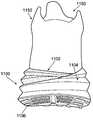
도 11a 내지 도 11c는 본 발명의 다른 예에 따른 신발류 물품의 다양한 도면을 제공하며;
도 12a 내지 도 12c는 본 발명의 다른 예에 따른 신발류 물품의 다양한 도면을 제공한다.The foregoing summary of the invention, as well as the following detailed description of the invention, will be better understood when taken in conjunction with the accompanying drawings, in which like reference numerals refer to the same or similar elements throughout the various figures in which the reference numerals are represented.
Figures 1A-1F illustrate a sole structure according to one example of the present invention;
2A to 2F show a sole structure according to another example of the present invention;
FIGS. 3A and 3B illustrate features of a sole structure according to another example of the present invention; FIG.
Figure 4 illustrates a heel region of a portion of a foam component that may be included in a sole structure according to some examples of the present invention;
Figure 5 illustrates a basketball according to one example of the present invention;
Figure 6 shows a running shoe according to one example of the present invention;
Figure 7 illustrates a traction according to one example of the present invention;
8A to 8F show a sole structure according to another example of the present invention;
9 is an exploded view of a sole structure according to another example of the present invention;
FIGS. 10A and 10B illustrate features of a sole structure according to another example of the present invention; FIG.
11a-11c provide various views of a footwear article according to another example of the present invention;
12A to 12C provide various views of a footwear article according to another example of the present invention.
본 발명에 따른 신발류 구조체 및 구성요소의 다양한 예의 하기의 설명에 있어서, 본 명세서의 일부를 형성하고, 본 발명의 태양이 실시될 수 있는 다양한 예시적인 구조 및 환경을 예시로서 나타낸 첨부 도면을 참조한다. 다른 구조 및 환경이 이용될 수 있고, 구조적 및 기능적 변형이 본 발명의 범위로부터 벗어남이 없이 구체적으로 설명되는 구조 및 기능으로부터 이루어질 수 있다는 것이 이해되어야 한다.In the following description of the various embodiments of footwear structures and components according to the present invention, reference is made to the accompanying drawings which form a part hereof and which illustrate, by way of example, various exemplary structures and environments in which aspects of the invention may be practiced . It is to be understood that other structures and environments may be utilized and structural and functional modifications may be made from structures and functions which are specifically described without departing from the scope of the present invention.
Ⅰ. 본 발명의 태양의 일반적인 설명Ⅰ. General description of aspects of the present invention
본 발명의 일부 태양은 적어도 하나의 보다 강성 및/또는 조밀성 케이지(보호) 구성요소(들) 및/또는 다른 보호 구성요소에 의해 부분적으로 덮이는 비교적 연질 및 경량의 폼 중창 구성요소를 포함하는 밑창 구조체 및/또는 신발류(예를 들면, 운동화류) 물품에 관한 것이다. 본 발명의 보다 구체적인 특징 및 태양이 하기에서 보다 상세하게 설명된다.Some aspects of the present invention include a relatively soft and lightweight foam midsole component that is partially covered by at least one more rigid and / or dense cage (protection) component (s) and / or other protective component Sole structure and / or footwear (e.g., athletic shoes) article. More specific features and aspects of the present invention are described in more detail below.
A. 본 발명의 예에 따른 밑창 구조체 및 신발류 물품의 특징A. Characteristics of the sole structure and footwear article according to the present invention example
본 발명의 일부 태양은 신발류 물품용 밑창 구조체, 및 이러한 밑창 구조체를 구비하는, 운동화류를 포함하는 신발류 물품(또는 다른 발-수용 장치)에 관한 것이다. 본 발명의 적어도 일부 예에 따른 신발류 물품용 밑창 구조체는 착용자 발의 적어도 힐 및 중족부 영역을 지지하기 위한 제1 폴리머 폼 부재를 포함할 수 있다. 이러한 제1 폴리머 폼 부재의 노출된 외측 에지는, 제1 폴리머 폼 부재의 안쪽 중족부 또는 전족부 영역으로부터, 후방 힐 영역 주위로 그리고 제1 폴리머 폼 부재의 바깥쪽 중족부 또는 전족부까지 연속적으로 연장되는 파형부 구조체를 포함한다. 이러한 파형부 구조체는 인접한 파형부 외측 리지 사이에 위치된 파형부 개재 영역에 의해 연결된 2개 내지 8개의 파형부 외측 리지를 포함할 수 있다.Some aspects of the invention relate to a sole structure for a footwear article, and a footwear article (or other foot-receiving device) comprising such a sole structure. The sole structure for a footwear article according to at least some examples of the present invention may comprise a first polymer foam member for supporting at least the heel and midsole region of the wearer's foot. The exposed outer edge of this first polymer foam member extends continuously from the inner mid- or forefoot region of the first polymer foam member to around the rear heel region and to the outer mid- or forefoot of the first polymer foam member And includes a corrugated sub-structure. Such corrugated sub-structures may include two to eight corrugated lateral ridges connected by corrugated sub-annular areas located between adjacent corrugated outer ridges.
본 발명의 적어도 일부 예에 따른 밑창 구조체는 폼 보호 구성요소 및/또는 폼 중창 구성요소 중 하나 이상의 바닥면(들) 상에(예를 들면, 노출된 공간들 중 하나 내에) 바닥창 구성요소(예를 들면, 고무, 파일론(phylon), 파일라이트(phylite), 열가소성 폴리우레탄 등으로 제조됨)를 포함할 수도 있다. 바닥창 구성요소(들)는 예를 들어 경도, 강도, 내마모성 및 (예를 들면, 밑창 구조체의 바닥면 상에 텍스처(texture), 클리트(cleat), 또는 다른 트랙션-향상 구조를 제공함으로써) 트랙션을 제공할 수 있다. 본 발명에 따른 일부 예시적인 구조체에서, 몇몇의 독립적인 바닥창 구성요소는 밑창 구조체의 바닥부 주위에서 별개의 다양한 위치에 제공된다. 바닥창 구성요소는 또한 경량의 중창 구성요소를 위한 "보호" 구성요소로 고려될 수도 있다.A sole structure in accordance with at least some examples of the present invention may include a bottom window component (e.g., a bottom window component) on one or more bottom surfaces (s) of a foam protection component and / Such as, for example, rubber, phylon, phylite, thermoplastic polyurethane, and the like. The bottom window component (s) may include, for example, hardness, strength, abrasion resistance and traction (e.g., by providing a texture, cleat, or other traction-enhancement structure on the bottom surface of the sole structure) Can be provided. In some exemplary structures in accordance with the present invention, several independent floor window components are provided at various different locations around the bottom of the sole structure. The bottom window component may also be considered a "protection" component for a lightweight midsole component.
원한다면, 본 발명의 적어도 일부 예에 따르면, 보다 경량이고 및/또는 덜 조밀한 폼 중창 재료 구성요소 및/또는 보다 조밀한 보호 구성요소(선택적으로, 보다 무겁거나 보다 조밀한 폴리머 폼 재료로 제조됨) 중 하나 이상의 외측부 에지의 적어도 일부 부분은 파형 구조체(하기에서 보다 상세하게 설명됨)를 포함할 수 있다. 부가적으로 또는 대안적으로, 원한다면, 폼 중창 구성요소의 적어도 일부 부분은 예를 들어 선택적으로 하나 이상의 보호 구성요소의 파형 구조체(이들이 파형인 경우)에 인접하여 파형 구조체를 포함할 수도 있다. 임의의 개수의 개별 파형 구조체가 본 발명으로부터 벗어남이 없이 다양한 구성요소 상에 가능하지만, 일부 예에서는, 상하 방향으로, 개별 밑창 구조체는 2개 내지 8개의 파형부를 포함하고, 일부 예에서는 3개 내지 6개의 파형부를 포함할 수도 있다.If desired, according to at least some examples of the present invention, a lighter and / or less dense foam core material component and / or a denser protective component (optionally made of a heavier or denser polymer foam material) May include a corrugated structure (described in more detail below). Additionally or alternatively, if desired, at least a portion of the foam midsole component may comprise a corrugated structure adjacent to, for example, the corrugated structures of the one or more protective components (if they are corrugated). Although any number of individual corrugated structures are possible on the various components without departing from the invention, in some instances, in the up-and-down direction, the individual sole structure includes two to eight corrugations, And may include six wave portions.
본 발명의 다른 예에 따른 밑창 구조체는 착용자 발의 적어도 힐 및 중족부 영역을 지지하기 위한 폴리머 폼 부재(선택적으로, 0.25g/㎤ 미만의 밀도를 갖는 폼 재료와 같은 경량의 저밀도 폴리머 폼 재료)를 포함할 수 있다. 이러한 폴리머 폼 부재의 노출된 외측 에지는,A sole structure according to another example of the present invention includes a polymer foam member (optionally, a lightweight low density polymer foam material such as a foam material having a density of less than 0.25 g / cm < 3 >) for supporting at least the heel and mid- . The exposed outer edge of such a polymer foam member,
제1 외측 파형부 리지, 제2 외측 파형부 리지, 제3 외측 파형부 리지, 제1 및 제2 외측 파형부 리지 사이에 위치된 제1 개재 영역, 및 제2 및 제3 외측 파형부 리지 사이에 위치된 제2 개재 영역을 포함하는 제1 파형부 구조체, 및A first outer-corrugated bulge, a second outer-corrugated bulge, a third outer-corrugated bulge, a first intervening region positioned between the first and second outer corrugated bulges, and a second intervening region between the second and third outer- A first wave-form portion structure including a second interleaved region located in the first wave-
제4 외측 파형부 리지, 제5 외측 파형부 리지, 및 제4 및 제5 외측 파형부 리지 사이에 위치된 제3 개재 영역을 포함하는 제2 파형부 구조체를 포함할 수 있으며,And a third intervening region positioned between the fourth outer-wave-shaped bulge, the fourth outer-wave bulge, the fifth outer-wave bulge, and the fourth and fifth outer-wave bulge,
제4 외측 파형부 리지는 제1 개재 영역에서 시작되고, 제5 외측 파형부 리지는 제2 개재 영역에서 시작된다. 폴리머 폼 부재의 노출된 외측 에지는 다른 파형부 구조체를 추가로 포함할 수 있으며, 예를 들어 그러한 파형부 구조체의 외측 파형부 리지는 제3 개재 영역에서 시작된다. 하나의 파형부 구조체는 밑창 구조체의 후방 힐 영역 주위로 연장될 수 있는 한편, 다른 파형부 구조체는 밑창 구조체의 측부 중족부 영역에 위치될 수 있다. 바닥창 구성요소는 폴리머 폼 부재의 바닥면과 결합될 수 있다.The fourth outer corrugated bulge starts in the first intervening area and the fifth outer corrugated bulge starts in the second intervening area. The exposed outer edge of the polymeric foam member may further comprise other corrugated sub-structures, for example the outer corrugated sub-ridges of such corrugated sub-structures start in the third interposed region. One corrugated subassembly may extend around the rear heel region of the sole structure while another corrugated side structure may be located in the side flank region of the sole structure. The bottom window component may engage the bottom surface of the polymer foam member.
본 발명의 일부 예에 따른 다른 예시적인 밑창 구조체는 착용자 발의 적어도 힐 영역을 지지하기 위한 제1 폴리머 폼 부재를 포함하며, 이러한 제1 폴리머 폼 부재는, (a) 바깥쪽 측벽, (b) 안쪽 측벽, (c) 안쪽 측벽 및 바깥쪽 측벽을 연결하는 후방 힐 벽, (d) 안쪽 측벽, 바깥쪽 측벽 및 후방 힐 벽을 연결하는 바닥 벽, 및 (e) 후방 힐 벽에 대향하는 개방 단부를 갖는 외측 쉘을 구성하고, 이러한 제1 폴리머 폼 부재는 밑창 구조체의 후방 힐 영역 주위로 연장된다. 제2 폴리머 폼 부재는 제1 폴리머 폼 부재의 외측 쉘에 의해 형성된 공간에 적어도 부분적으로 수용되는 힐 부분을 구비하며, 제2 폴리머 폼 부재의 전족부 단부는 제1 폴리머 폼 부재의 개방 단부를 지나서 연장된다. 이러한 제2 폴리머 폼 부재는 제1 폴리머 폼 부재의 밀도보다 작은 밀도를 가지며, 제2 폴리머 폼 부재의 바닥면의 일부분은 신발류 물품의 바닥 전족부 영역에서 노출된다. 원한다면, 보호 요소가 바닥 전족부 영역에서 제2 폴리머 폼 부재의 바닥면과 결합될 수 있다.Another exemplary sole structure according to some embodiments of the present invention includes a first polymer foam member for supporting at least a heel region of a wearer's foot, the first polymer foam member comprising: (a) an outer sidewall, (b) (C) a rear heel wall connecting the inner side wall and the outer side wall, (d) a bottom wall connecting the inner side wall, the outer side wall and the rear heel wall, and (e) And this first polymer foam member extends around the rear heel region of the sole structure. The second polymer foam member having a heel portion at least partially received in a space defined by the outer shell of the first polymer foam member and the forefoot end of the second polymer foam member extending beyond the open end of the first polymer foam member do. This second polymer foam member has a density less than the density of the first polymer foam member and a portion of the bottom surface of the second polymer foam member is exposed in the bottom forefoot region of the footwear article. If desired, the protective element can be combined with the bottom surface of the second polymer foam member in the bottom forefoot region.
본 발명의 일부 예에 따른 또 다른 밑창 구조체는, (a) 착용자 발의 전체 발바닥 표면을 지지하기 위한 폴리머 폼 부재로서, 0.25g/㎤ 미만의 밀도를 갖는 폼 재료를 포함하는, 폴리머 폼 부재, 및 (b) 이 폴리머 폼 부재의 바닥면의 표면적의 적어도 80%를 덮도록 폴리머 폼 부재와 결합되는 보호 부재를 포함하며, 보호 부재는 웨브 베이스면을 구성하고, 복수의 트랙션 요소가 웨브 베이스면으로부터 하방으로 연장되고, 복수의 트랙션 요소들 사이의 위치에서의 대부분의 웨브 베이스면의 두께는 2㎜ 미만의 두께이다.Another shoe structure according to some embodiments of the present invention is a polymer foam member for supporting an entire sole surface of a wearer's foot, the polymer foam member comprising a foam material having a density of less than 0.25 g / cm < 3 & (b) at least 80% of the surface area of the bottom surface of the polymeric foam member, wherein the protective member comprises a web base surface, and wherein a plurality of traction elements extend from the web base surface And the thickness of most web base surfaces at positions between the plurality of traction elements is less than 2 mm thick.
본 발명의 다른 추가적인 태양은, 상기에서 설명된(그리고 하기에서 보다 상세하게 설명되는) 다양한 타입의 밑창 구조체와 결합되는 갑피(예를 들면, 통상의 디자인, 구성 또는 구조를 포함하는 임의의 원하는 디자인, 구성 또는 구조를 가짐)를 포함하는 신발류 물품에 관한 것이다.Another additional aspect of the present invention is to provide a sole that is combined with various types of sole structures described above (and described in more detail below) (e.g., any desired design including a conventional design, , Configuration, or structure).
본 발명의 추가적인 태양은 신발류 물품 또는 그것의 다양한 구성요소를 제조하는 방법에 관한 것이다. 본 발명의 보다 구체적인 하나의 태양은 전술한 다양한 타입 및 구성의 신발류 물품용 밑창 구조체를 제조하는 방법에 관한 것이다. 본 발명의 태양에 따른 밑창 구조체 및 신발류 물품의 다양한 구성요소 및 부품이 본 기술분야에 통상적으로 알려지고 사용되는 방식으로 제조될 수 있지만, 본 발명의 방법 태양의 예는 전술한 다양한 구조체를 생산하는 방식으로 밑창 구조체 및/또는 신발류 부품들을 조합하고 그들을 서로 결합하는 것에 관한 것이다.A further aspect of the invention relates to a method of manufacturing a footwear article or its various components. One more specific aspect of the present invention is directed to a method of making the sole structure for footwear articles of the various types and configurations described above. While the various components and components of the sole structure and footwear article in accordance with aspects of the present invention may be manufactured in a manner commonly known and used in the art, an example of a method embodiment of the present invention may be used to produce the various structures described above To combining the sole structure and / or footwear parts and bonding them together.
상기에서는 본 발명에 따른 특징, 태양, 구조 및 배열의 일반적인 설명이 제공되었다고 한다면, 하기에는 본 발명에 따른 특정의 예시적인 밑창 구조체, 신발류 물품 및 방법의 보다 상세한 설명이 이어진다.In the foregoing, a general description of features, aspects, structures and arrangements in accordance with the present invention is provided, followed by a more detailed description of certain exemplary sole structures, footwear articles and methods according to the present invention.
Ⅱ. 본 발명에 따른 예시적인 밑창 구조체 및 신발류 물품의 상세한 설명Ⅱ. Detailed description of an exemplary sole structure and footwear article according to the present invention
도면 및 하기의 논의를 참조하면, 본 발명에 따른 다양한 밑창 구조체, 신발류 물품 및 그 특징부가 개시된다. 도시되고 논의되는 밑창 구조체 및 신발류는 운동화이며, 이러한 신발류의 다양한 태양에 대해 개시된 개념은, 워킹화, 테니스화, 축구화, 미식축구화, 농구화, 런닝화, 크로스-트레이닝화, 미끄럼방지 신발, 골프화 등을 포함하지만 이에 한정되지 않는 광범위한 운동화류 스타일에 적용될 수 있다. 또한, 본 발명의 적어도 일부의 개념 및 태양은 워크 부츠(work boots), 샌들(sandal), 로퍼(loafer), 드레스화를 포함하는 광범위한 비운동화류에 적용될 수도 있다. 따라서, 본 발명은 본 명세서에 개시된 정확한 실시예에 한정되지 않고, 일반적으로 신발류에 적용한다.Referring to the drawings and discussion below, various sole structures, footwear articles and their features are disclosed in accordance with the present invention. The sole structures and footwear shown and discussed are footwear and the concepts disclosed for the various aspects of such footwear include walking, tennis shoes, soccer shoes, soccer shoes, basketball shoes, running shoes, cross-training shoes, The present invention can be applied to a wide range of athletic shoes not limited thereto. In addition, at least some of the concepts and aspects of the present invention may be applied to a wide range of non-sneakers, including work boots, sandals, loafers, dressings. Therefore, the present invention is not limited to the precise embodiment disclosed herein, but generally applies to footwear.
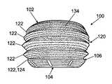
도 1a 내지 도 1f는 본 발명의 적어도 일부의 태양 및 특징을 포함하는 신발류 물품용의 예시적인 밑창 구조체(100)의 다양한 도면을 도시하고 있다. 본 개시내용을 위해, 도 1a에 도시된 바와 같이, 신발류 물품의 부분(및 그것의 다양한 구성요소 부품)은 신발류가 적절한 크기의 발에 착용되는 경우에 신발류 물품의 그러한 부분에 또는 그 부근에 위치된 발의 영역에 기초하여 식별될 수 있다. 예를 들어, 도 1a에 도시된 바와 같이, 신발류 물품 및/또는 밑창 구조체는 발의 전방에 "전족부 영역", 발의 중간 또는 아치형 영역에 "중족부" 영역, 및 발의 후방에 "힐 영역"을 갖는 것으로 고려될 수 있다. 신발류 및/또는 밑창 구조체는 "바깥쪽 측부(lateral side)"(발의 "외측" 또는 "새끼발가락측") 및 "안쪽 측부(medial side)"(발의 "내측" 또는 "엄지발가락측")를 또한 포함한다. 전족부 영역은 일반적으로 중족골(metatarsal)과 지골(phalangeal)을 연결하는 관절 및 발가락에 대응하는 신발류의 부분을 포함한다. 중족부 영역은 일반적으로 발의 아치형 영역에 대응하는 신발류의 부분을 포함한다. 힐 영역은 일반적으로 종골(calcaneus bone)을 포함하는 발의 후방 부분에 대응한다. 신발류의 바깥쪽 및 안쪽 측부는 전족부 영역, 중족부 영역 및 힐 영역을 통해 연장되고, 일반적으로 신발류의 대향 측부에 대응한다(그리고, 길이방향 중심축에 의해 분리된 것으로서 고려될 수도 있음). 이들 영역(도 1a에서 분할선에 의해 분리되어 있지만) 및 측부는 신발류의 정확한 영역을 구획하도록 의도된 것은 아니다. 오히려, 용어 "전족부 영역", "중족부 영역", "힐 영역", "바깥쪽 측부" 및 "안쪽 측부"는 이어지는 설명을 돕기 위해 신발류 물품 및 그것의 다양한 구성요소의 대략적인 영역을 표현하도록 의도된다.FIGS. 1A-1F illustrate various views of an exemplary
도 1a는 밑창 구조체(100)의 평면도를 도시하고, 도 1b는 바깥쪽 측면도를 도시하고, 도 1c는 안쪽 측면도를 도시하며, 도 1d는 저면도를 도시하고, 도 1e는 힐 또는 후방 측면도를 도시하고, 도 1f는 발가락 또는 전방 측면도를 도시하고 있다. 도 1a 내지 도 1f에 도시된 바와 같이, 본 예시적인 밑창 구조체(100)는 착용자 발의 전체 발바닥 표면을 지지하기 위해, 즉 밑창(100)의 후방 힐 영역으로부터 밑창(100)의 전방 발가락 영역까지 그리고 밑창(100)의 바깥쪽 측부 에지로부터 안쪽 측부 에지까지, 이러한 특정 구조체(100)에서 연속적으로 연장되는 단일의 중창 구성요소(102)를 포함한다. 다른 중창 구성이 가능하지만, 본 발명의 일부 예에 따르면, 중창 구성요소(102)는 폼 재료(예를 들면, 에틸렌비닐아세테이트("EVA") 폼, 폴리우레탄 폼, 파일론 폼 등)를 구성할 수 있다. 중창 구성요소(102)의 상단면(102a)은 예를 들어 착용자 발의 발바닥 표면을 편안하게 지지하고 및/또는 그 위치설정을 돕기 위한 윤곽을 가질 수 있다.1B shows an outline side view, FIG. 1C shows an inner side view, FIG. 1D shows a bottom view, FIG. 1E shows a heel or rear side view And Fig. 1F shows a toe or front side view. 1A-1F, the exemplary
본 발명의 일부 예에서, 중창 구성요소(102)는 0.25g/㎤ 미만의 밀도(일부 예에서는, 0.2g/㎤ 미만, 0.075 내지 0.2g/㎤의 범위 내, 및 심지어 0.1 내지 0.18g/㎤의 범위 내의 밀도)를 갖는 폼 재료로 적어도 부분적으로 제조된다. 원한다면, 중창 구성요소(102)의 폼 재료는 그 내부에 형성된 하나 이상의 개구부를 포함하고 및/또는 그것과 함께 유체-충전식 블래더(bladder), 기계적 충격 흡수 부재 등과 같은 다른 충격력 감쇠 구성요소를 포함할 수도 있다. 본 발명의 특정 실시예에서, 전체 중창 구성요소(102)는 이러한 경량 폼 재료(예를 들면, 전술한 바와 같은 밀도 특징을 가짐)를 구성하고, 착용자의 전체 발(예를 들면, 전체 발바닥 표면)을 지지하도록 연장된다. 도 1a 내지 도 1f에 도시된 바와 같은 예시적인 구조체(100)에서, 폼 중창 구성요소(102)는 결합선(junction line)(106)(이러한 결합선(106)은 이들 도면에서 재료들(102/104) 사이의 위치 변화를 강조하기 위해 도면에 도시 보조선으로서 제공됨)에 의해 보호 구성요소(104)(예를 들면, 보다 조밀하거나 보다 경질인 다른 중창 재료(예컨대, 폴리머 폼 재료); 바닥창 재료; "케이지" 또는 "캐리어 부재" 등 중 하나 이상)와 별개의 부품으로 도시되어 있다. 본 도시된 예에서, 중창 구성요소(102)는 대체로 보호 구성요소(104) 위에 놓인다(그리고, 보호 구성요소(104)에 의해 적어도 부분적으로 수용될 수도 있음). 다른 선택으로서, 중창 구성요소(102)는 원한다면 다중 구성요소 중창(예를 들면, 폼) 부품으로 제조될 수 있으며, 및/또는 밑창 구조체(100)는 다중 보호 구성요소 부품(104)을 포함할 수도 있다.In some examples of the present invention, the
일부의 훨씬 더 특정된 예로서, 중창 구성요소(102)의 적어도 일부는 예를 들어 그 전체가 본 명세서에 참조로 합체되는 미국 특허 제7,941,938호에 개시된 바와 같은 폼 재료로 제조될 수도 있다. 본 발명에 따른 적어도 일부의 예시적인 밑창 구조체(100)에서, 중창 구성요소(102)의 모든 부분, 실질적으로 모든 부분, 또는 적어도 일부 부분은 약 10 내지 약 100 백분율(part per hundred)의 수소화 또는 비수소화 아크릴로니트릴 부타디엔 코폴리머, 0 내지 약 40 백분율의 개질된 수소화 아크릴로니트릴 부타디엔 코폴리머, 및 0 내지 약 90 백분율의 알파 올레핀 코폴리머의 반응 생성물과, 폼 재료를 형성하기에 적합한 양의 적어도 하나의 첨가제를 포함하는 폼 재료를 포함할 수도 있다. 이러한 폼 재료는 경량의 스폰지 느낌을 가질 수 있다. 폼 재료의 밀도는 일반적으로 0.25g/㎤ 미만, 0.20g/㎤ 미만, 18g/㎤ 미만, 0.15g/㎤ 미만, 0.12g/㎤ 미만, 및 일부 예에서는 0.10g/㎤ 미만일 수 있다. 예시적인 범위로서, 경량의 폼 밀도는 예를 들어 0.05 내지 0.25g/㎤의 범위 또는 상기에 언급된 다양한 범위 내에 있을 수 있다.As a more specific example of some, at least some of the
또한, 본 발명의 적어도 일부 예에 따르면, 중창 구성요소(102)를 위한 폼 재료의 탄성은 40% 초과, 45% 초과, 적어도 50%, 및 일 태양에서는 50 내지 70%일 수 있다. 영구 압축률(compression set)은 60% 이하, 50% 이하, 45% 이하, 및 일부 예에서는 20 내지 60%의 범위 내일 수 있다. 본 예시적인 중창 구성요소(102)를 위한 폼 재료의 경도(Durometer Asker C)는 예를 들어 신발류의 유형에 따라, 예컨대 25 내지 50, 25 내지 45, 25 내지 35, 또는 35 내지 45일 수 있다. 폼 재료(102)의 인장 강도는 적어도 15kg/㎠, 및 전형적으로 15 내지 40kg/㎠일 수 있다. 연신율 %는 150 내지 500, 전형적으로 250 초과이다. 인열 강도(tear strength)는 6 내지 15kg/㎝, 전형적으로 7kg/㎝ 초과이다. 본 발명에 따른 적어도 일부의 예시적인 구성에서, 중창 구성요소(102)의 적어도 일부 부분의 폼 재료는 낮은 에너지 손실을 가질 수 있고, 전통적인 EVA 폼보다 경량일 수도 있다. 에너지 손실은 30% 미만, 선택적으로는 약 20% 내지 약 30%의 범위 내일 수 있다. 추가적인 예로서, 원한다면, 중창 구성요소(102)의 적어도 일부 부분은 미국 오레곤주 비버턴 소재의 나이키 인크(NIKE, Inc.)로부터 입수 가능한 신발류 제품의 LUNAR 패밀리에 사용되는 폼 재료로 제조될 수도 있다.Also, according to at least some examples of the present invention, the elasticity of the foam material for the
상기 단락들에서는 본 발명의 일부 예에 따른 중창 구성요소(102)를 위한 폼 재료의 잠재적인 특성 및 특징이 설명되고 있지만, 본 기술분야의 숙련된 자는 중창 구성요소(102)가 본 발명으로부터 벗어남이 없이 다른 원하는 특성, 특징 및/또는 특징의 조합을 가질 수도 있다는 것을 인식할 것이다. 다른 경량 및/또는 저밀도 폼이 또한 사용될 수도 있다. 하기에서 보다 상세하게 설명되는 보호 구성요소(104) 때문에, 경량의 폼 중창 구성요소(102)는 사용 시에 지면에 직접 접촉하기에 충분한 경도, 내구성 및/또는 내마모성을 반드시 가질 필요는 없다(충격이 보다 큰 일부의 지면 접촉 위치에는 적어도 아님).While the above paragraphs describe the potential features and characteristics of the foam material for the
본 예시적인 밑창 구조체(100)에서의 보호 구성요소(104)는 본 발명으로부터 벗어남이 없이 임의의 원하는 재료로 제조될 수 있다. 예를 들면, 보호 구성요소(104)는 고무, 열가소성 폴리우레탄(TPU) 등과 같은 통상의 바닥창 재료로 제조될 수도 있다. 다른 예로서, 보호 구성요소(104)는 상기에서 언급된 미국 특허 제7,941,938호에 개시된 것과 같은 폴리머 폼 케이지 또는 캐리어 재료로 적어도 부분적으로 제조될 수 있다. 통상의 다른 폴리머 폼 재료가 또한 보호 구성요소(104)에 사용될 수도 있다.The
폼 중창 구성요소(102) 및 보호 구성요소(104)는 본 기술분야에 알려지고 사용되는 바와 같은 통상의 방식을 포함하여, 본 발명으로부터 벗어남이 없이 임의의 원하는 방식으로 서로 결합될 수 있다. 본 도시된 예에서, 보호 구성요소(104)는 폴리머 폼 구성요소(102)의 바닥면 및/또는 측면에 형성된 하나 이상의 리세스(recess) 내에 끼워진다. 리세스(들)는, 존재한다면, 경량의 폼 구성요소(102)가 형성되는 몰딩 공정(또는 다른 성형 공정) 동안에 형성될 수 있다. 대안적으로, 리세스는 경량의 폼 구성요소(102)가 형성된 후에, 예를 들어 절삭 또는 연삭(grinding) 동작에 의해 제조될 수도 있다. 보호 구성요소(104)는 본 기술분야에 알려지고 사용되는 바와 같은 통상의 트랙션 요소를 포함하는, 헤링본(herringbone) 구조, 융기형 리브 또는 리지, 리세스형 홈 등과 같은, 사용 시에 지면 또는 다른 접촉면과 결합하기 위한 트랙션 요소 또는 다른 특징부를 포함할 수 있다. 추가적인 예로서, 보호 구성요소(104)의 바닥면은 제거가능한 클리트를 수용하기 위한 리셉터클(receptacle)을 포함하도록 형성될 수 있고, 및/또는 보호 구성요소의 바닥면으로부터 연장되는 실제 클리트 요소를 포함하도록 형성될 수도 있다.The
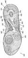
또한 도 1d에 도시된 바와 같이, 보호 구성요소(104)의 바닥면은 중창 구성요소(102)의 바닥면을 완전히 덮을 필요는 없다. 오히려, 보호 구성요소(104)에는, 경량의 폼 재료(102)의 바닥면을 노출시키는 일부의 공간 또는 구멍이 제공될 수도 있다. 이러한 특징은 몇 개의 잠재적인 이점을 제공할 수 있다. 예를 들면, 보호 구성요소(104)의 일부를 제거함으로써, 밑창 구조체(100)의 중량을 경량화할 수 있다. 추가적으로, 도 1d에 도시된 바와 같이, 보호 구성요소(104)에는, 틈새(break) 또는 갭이 보호 구성요소(104)의 원하는 굽힘 라인(예를 들면, 도 1d에 도시된 바와 같이, 전족부 영역에서의 기다란 슬롯 또는 갭)을 따라 제공될 수 있으며, 이에 의해 전체 밑창 구조체(100)의 전반적인 가요성(및 선택적으로 보다 자연스러운 가요성)을 유지하는 것을 돕는다. 본 예시적인 밑창 구조체(100)의 힐 영역에 있어서의 보호 구성요소(104)의 큰 개구부는 힐에 대한 비교적 크고 연질인 "크래쉬 패드(crash pad)"를 제공하여, 예를 들어 착용자 힐이 지면과 부딪칠 때, 예컨대 걸음을 내딛거나 점프를 착지할 때에 보다 양호한 편안함 및 느낌을 제공한다. 본 기술분야에 숙련된 자는, 본 개시내용의 이점을 고려해 볼 때, 보호 구성요소(104)의 개구부가 선택적이고, 존재한다면 본 발명으로부터 벗어남이 없이 임의의 원하는 크기, 형상 및/또는 개수로 제공될 수 있다는 것을 이해할 것이다. 그러나, 바람직하게는, 밑창 구조체(100)의 바닥면 상의 고마모 영역은 중창 구성요소(102)의 구조적 건전성(structural integrity)을 보호하는 것을 돕기 위해 경량의(그리고 보다 취약한) 폴리머 중창 구성요소(102) 위에 놓이는 보호 구성요소(104)의 일부 층을 포함한다.1D, the bottom surface of the
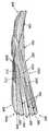
도 1c 및 도 1d에 가장 잘 도시된 바와 같이, 본 예시적인 밑창 구조체(100)는 밑창 구조체의 중앙 또는 중족부 영역에 제공된 다른 요소, 즉 지지 플레이트(108)를 포함한다. 이러한 지지 플레이트(108)는 이러한 밑창 구조체(100)의 아치형 영역에 대한 추가적인 지지를 제공한다. 도 1c 및 도 1d에서, 지지 플레이트(108)는 결합선(110)에 의해 중창 구성요소(102) 및/또는 보호 구성요소(104)와 분리된 것으로 도시되어 있다. 이러한 결합선(110)은 이들 도면에서 지지 플레이트(108)와 재료들(102/104) 사이의 위치 변화를 강조하기 위해 도면에 도시 보조선으로서 제공된다. 본 도시된 예에서, 지지 플레이트(108)는 적어도 밑창 구조체(100)의 아치형 영역에서 중창 구성요소(102)와 보호 구성요소(104) 사이에 적어도 부분적으로 샌드위치되거나 또는 적층될 수 있다. 지지 플레이트(108)는 접착제 또는 시멘트(cement)에 의해, 기계적 커넥터에 의해, 및/또는 본 기술분야에 알려지거나 사용되는 통상의 방식을 포함하는 임의의 다른 원하는 방식에 의해 중창 구성요소(102) 및/또는 보호 구성요소(104) 중 하나 이상과 결합될 수 있다. 지지 플레이트(108)는, 본 기술분야에 알려지고 사용되는 바와 같은 통상의 아치형 지지 재료 및/또는 부품을 포함하여, 본 발명으로부터 벗어남이 없이 임의의 원하는 개수의 피스 또는 부품, 및/또는 임의의 원하는 재료로 제조될 수 있다. 일부의 보다 특정된 재료의 예는 열가소성 폴리우레탄, 나일론계 폴리머 재료(예를 들면, PEBAX), 탄소 섬유 보강 폴리머 재료, 유리 섬유 보강 폴리머 재료, 다른 복합 재료 등을 포함한다.As best shown in FIGS. 1C and 1D, the exemplary
도 1a 내지 도 1f는 본 발명의 적어도 일부 예에 따른 밑창 구조체(100)에 포함될 수 있는 다른 특징부를 도시한다. 이들 도면에 도시된 바와 같이, 중창 폼 구성요소(102) 및/또는 보호 구성요소(104)의 외측 에지 또는 측부의 적어도 일부 부분은 "파형 구조체"(120)를 포함할 수 있다. 본 명세서에 사용되는 바와 같이, 용어 "파형부 구조체(billowed structure)" 또는 "파형부 구조체(billows structure)"는 요소의 외부면 형상이 파형부, 예를 들어 일련의 웨이브 피크(최외측 부분 또는 리지) 및 웨이브 피크들 사이의 밸리을 갖는 웨이브형 구조체의 외부면 형상을 갖는 것을 의미한다. 밑창 구조체에서, "파형 구조체"는 통상의 파형부의 동일한 방식으로 팽창 및 압축할 필요는 없으며, 오히려 그러한 용어는 구조체의 외부면의 형상과 보다 일반적으로 관련된다. 도시된 예시적인 밑창 구조체(100)에서, 경량의 중창 폼 구성요소(102)는 일련의 4½ 파형부(122)(예를 들면, 후방 힐 영역 주위에 4개의 적층된 디스크처럼 보임)를 가지며, 보호 구성요소(104)는 ½ 파형부(124)(이러한 밑창 구조체(100)에서 최하부측 파형부를 완성하기 위해 중창 폼 구성요소(102)의 바닥의 ½ 파형부(122)와 결합함)를 포함한다. 파형 구조체(120)의 적어도 일부 부분은, 예를 들어 중창 구성요소(102)가 (적어도 힐 영역에서) 착용자 발 주위를 적어도 부분적으로 감싸도록, 중창 구성요소(102)의 상단면(102a)으로부터 위로 융기된 중창 구성요소(102)(및 그 파형 구조체(120))의 측벽 상에 제공될 수 있다. 일부의 보다 특정된 예에서, 중창 구성요소(102)의 외측 쉘(파형부 구조체(120)가 형성되어 있음)은 바깥쪽 측벽(130), 안쪽 측벽(132), 안쪽 측벽(132) 및 바깥쪽 측벽(130)을 연결하는 후방 힐 벽(134), 및 안쪽 측벽(132), 바깥쪽 측벽(130) 및 후방 힐 벽(134)을 연결하는 상단 발바닥 지지면(102a)을 포함할 수 있다. 상단 발바닥 지지면(102a)은 상단면(102a)으로부터, 예를 들어 중앙 힐 영역에서 약 10 내지 20㎜만큼 및/또는 전족부 영역(예를 들면, 중족골 헤드 지지 영역)에서 약 8 내지 16㎜만큼 하방으로 연장되는 폴리머 폼의 층(선택적으로, 그 내부에 하나 이상의 유체 충전식 블래더(bladder)가 포함됨)을 구성할 수 있다. 벽(130, 132, 134)은 상단면(102a)으로부터 상방으로 연장될 수 있으며, 테이퍼지거나 다양한 높이, 예를 들어 중족부 영역에서 0 내지 5㎜로부터 후방 힐 영역에서 25 내지 50㎜(또는 심지어 그 이상)를 가질 수 있다. 파형부 구조체(120)의 4½ 파형부의 적어도 일부 부분은 바깥쪽 측벽(130), 후방 힐 벽(134) 및 안쪽 측벽(132)의 외부면 주위로 연속적으로 연장될 수 있다.1A-1F illustrate other features that may be included in the
파형 구조체(120)의 크기, 개수, 형상 및/또는 다른 특징은 신발류 물품의 느낌을 제어하도록 선택될 수 있다. 전형적으로, 파형부가 깊을수록(즉, 웨이브 피크에서부터 인접한 밸리의 바닥까지의 치수가 클수록) 보다 큰 반응감(예를 들면, 원래 형상으로의 보다 빠른 복귀)을 제공한다. 중창 구성요소(들)(102) 및/또는 보호 구성요소(들)(104)의 크기, 밀도 및/또는 경도는 또한 착용자 발에 대한 밑창 구조체(100)의 느낌에 대한 제어를 가능하게 하도록 제어될 수도 있다. 본 도시된 예시적인 밑창 구조체(100)의 파형부 구조체(120)는 중창 구성요소(102)의 안쪽 중족부 또는 전족부 영역(도 1c 참조)으로부터 중창 구성요소(102)의 바깥쪽 중족부 또는 전족부 영역(도 1d 참조)까지 연속적으로 그리고 중단없이 연장된다. 본 특정의 전체 파형부 구조체(120)는 5개의 파형부 외측 리지를 포함하며, 상기 5개의 파형부 외측 리지는 이 5개의 파형부 외측 리지 중 인접한 파형부 외측 리지 사이에 위치된 4개의 파형부 개재 영역에 의해 연결된다.The size, number, shape, and / or other features of the
파형부 구조체는 본 발명으로부터 벗어남이 없이 다양한 형태를 취할 수 있다. 예를 들면, 도 1b, 도 1c, 도 1e 및 도 1f는 개별 파형부의 벽이 "단차" 구성을 갖고 각각의 개별 파형부의 최외측 리지가 비교적 뾰족한 코너부를 구성하는 것을 도시한다. 이것은 필수 조건은 아니다. 추가적인 예로서, 원한다면, 파형부 측벽은 매끄럽고, 직선형이고 및/또는 곡선형일 수 있다. 추가적으로, 각 파형부의 최외측 에지 또는 리지는 본 발명으로부터 벗어남이 없이 덜 뾰족한 코너부로서 이루어지고, 매끄럽게 만곡되고, 칸막이되는 등등일 수 있다. 또한, 파형부 구조체가 벽(130, 132, 134)의 대향하는 내부측에서 유사하게 보일 수 있지만(중공형인 파형부 피크를 가짐; 도 9 참조), 본 도시된 실시예에서는, 벽(130, 132, 134)의 내부면은 매끄럽다(예를 들면, 이들 파형부는 중실형이고 중공형이 아님).The corrugated sub-structure may take various forms without departing from the present invention. For example, Figures 1B, 1C, 1E and 1F illustrate that the walls of the individual corrugated portions have a "stepped" configuration and the outermost ridges of each individual corrugated portion constitute relatively sharp corners. This is not a prerequisite. As a further example, if desired, the corrugated side wall may be smooth, straight and / or curved. Additionally, the outermost edges or ridges of each corrugated portion may be formed as less sharp corners without departing from the present invention, smoothly curved, partitioned, and the like. Also, although the corrugated structure can be seen similarly on the opposite interior side of the
또한, 본 도시된 예시적인 밑창 구조체(100)에서, 중창 구성요소(102)의 후방 힐 영역에서, 가장 높은 파형부 외측 리지(최상단 파형부 리지)는 밑창 구조체(100)가 수평면 상에 배향되는 경우에 적어도 1.5인치의 수직 거리만큼 (바닥에서) 최하측 파형부 외측 리지로부터 수직으로 분리된다. 추가적으로 또는 대안적으로, 본 밑창 구조체(100)에 있어서, 중창 구성요소(102)의 후방 힐 영역에서, 중앙 파형부 외측 리지(본 예에서는 제3 파형부)는 밑창 구조체(100)가 수평면 상에 배향되는 경우에 가장 긴 거리로 후방으로 연장된다. 이들 특징은 예를 들어 도 1b 및 도 1c에서 가장 잘 볼 수 있다.In addition, in the exemplary exemplary
또한, 도 1b, 도 1c 및 도 1f에서 가장 잘 도시된 바와 같이, 본 예시적인 밑창 구조체(100)의 보호 구성요소(104)의 노출된 외측 에지는 밑창 구조체(100)의 전방 발가락 영역 주위로 연장되는 파형부 구조체(140)를 포함한다. 본 예시적인 파형부 구조체(140)는 3개의 파형부 외측 리지를 포함하며, 상기 3개의 파형부 외측 리지는 이 3개의 파형부 외측 리지 중 인접한 파형부 외측 리지 사이에 위치된 2개의 파형부 개재 영역에 의해 연결된다. 도시된 바와 같이, 본 예시적인 밑창 구조체(100)의 보호 구성요소(104)의 파형부 구조체(140)는 중창 구성요소(102)의 파형부 구조체(120)와 연속하지 않는다. 오히려, 보호 구성요소(104)의 파형부 구조체(140)는 밑창 구조체(100)의 바깥쪽 전족부 영역 및 안쪽 전족부 영역에 각각 제공된 전이 영역(142, 144)에 의해 중창 구성요소(102)의 파형부 구조체(120)로부터 분리된다. 전이 영역(142 및/또는 144)은 중창 구성요소(102), 보호 구성요소(104) 및/또는 다른 밑창 구성요소로 이루어질 수 있다. 또한, 전이 영역(142, 144)은 다른 파형부 구조체, 하나 이상의 융기형 리브 또는 다른 지지 구성요소 등을 포함하는 임의의 원하는 구조체를 가질 수도 있다.1B, 1C, and 1F, the exposed outer edge of the
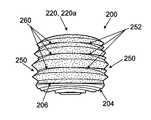
도 1a 내지 도 1f에 도시된 밑창 구조체(100)는 개별 파형부(122, 124)의 적어도 일부가 중창 구성요소(들)(102) 및/또는 보호 구성요소(들)(104) 주위로 그들의 바깥쪽 측단부로부터 그들의 안쪽 측단부까지 연속적으로 그리고 중단없이 연장되는 파형부 구성체(120)를 갖는다. 이것은 필수 조건은 아니다. 오히려, 도 2a 내지 도 2f는 도 1a 내지 도 1f의 밑창 구조체(100)와 유사한 부품 및 구조를 갖지만 상이한 파형부 구성체를 갖는 유사한 밑창 구조체(200)를 도시한다.The
간략화를 위해, 도 1a 내지 도 1f와 도 2a 내지 도 2f 사이의 유사한 부품은 본 명세서에서 상세하게 설명되지 않을 것이다. 오히려, 이어지는 논의에서는, 도 1a 내지 도 1f에 도시된 것과 비교해서 도 2a 내지 도 2f에 도시된 구조 사이의 차이점에 초점이 맞춰질 것이다. 본 기술분야에 숙련된 자가 이해할 수 있는 바와 같이, 도 2a 내지 도 2f에 대하여 하기에서 상세하게 설명되지 않는 부품은 도 1a 내지 도 1f에 대하여 상기에서 설명된 그러한 유사한 부품 및 구조와 동일하거나 유사한 구조 및/또는 동일하거나 유사한 특징 및/또는 옵션을 가질 수 있다.For the sake of simplicity, similar components between Figs. 1A-1F and Figs. 2A-2F will not be described in detail herein. Rather, in the following discussion, the focus will be on differences between the structures shown in Figs. 2A-2F as compared to those shown in Figs. 1A-1F. As will be understood by those skilled in the art, the parts not described in detail below with respect to Figs. 2A-2F are similar or similar to those similar parts and structures described above with respect to Figs. IA- And / or the same or similar features and / or options.
개별 파형부(122, 124)의 적어도 일부가 중창 구성요소(들)(102) 및/또는 보호 구성요소(들)(104) 주위로 그들의 바깥쪽 측단부로부터 그들의 안쪽 측단부까지 연속적으로 그리고 중단없이 연장되는, 도 1a 내지 도 1f에 도시된 파형부 구성체(120)와 달리, 도 2a 내지 도 2f의 파형부 구성체(220)는 혼합형 또는 인터위빙형 파형부를 포함한다. 도 2b, 도 2c 및 도 2e에서 가장 잘 보이는 바와 같이, 본 밑창 구조체(200)의 후방 힐 영역에서의 파형부 구성체(220a)는 도 1a 내지 도 1f의 밑창 구조체(100)의 후방 힐 영역에서의 파형부 구성체(120)의 후방 힐 영역에서와 유사한 파형부 구성을 갖는다(예를 들면, 5개의 파형부 외측 에지 및 4개의 파형부 개재 영역을 가짐). 그러나, 또한 도 2b, 도 2c 및 도 2e에서 가장 잘 보이는 바와 같이, 본 예시적인 밑창 구조체(200)에서의 파형부 구성체(220)는 바깥쪽 힐 영역 및 안쪽 힐 영역을 따라 그리고 이들 영역으로부터 전방으로 연장되는 상이한 구성을 갖는다. 보다 상세하게는, 도 2b에 도시된 바와 같이, 새로운 파형부 시리즈(220b)는 후방 파형부 구성체(220a)의 상단 3개의 파형부 사이에 제공된 개재 영역(250) 내의 힐 영역에서 시작된다. 도 2b에서는, 새로운 파형부 시리즈(220b)의 새로운 파형부의 시작점이 개재 영역(250) 내의 지점(252)에 도시되어 있다. 이들 시작 지점(252)으로부터, 3개의 개재 파형부가 보다 큰 폭 및 높이로 테이퍼져서 그 최외측 지점(254)의 양 측부에 최외측 파형부 리지를 형성한다. 또한, 새로운 파형부 시리즈(220b)의 개재 파형부는 후방 힐 파형부 시리즈(220a)를 완전히 덮치기에 충분히 큰 크기로 테이퍼진다(예를 들면, 후방 힐 파형부(220a)가 새로운 파형부 시리즈(220b)의 개재 영역 내의 위치에 시작 지점(220f)을 갖는 것에 주목하자). 추가적으로, 필수 조건은 아니지만, 도 2b에 도시된 예시적인 밑창 구조체(200)에서, 새로운 파형부 시리즈(220b)의 외측 리지(254)는 그 피크 영역으로부터 단부 지점(256)까지 이동함에 따라 크기가 감소하는 방향으로 테이퍼진다. 도 2b에 도시된 바와 같은 다른 파형부 시리즈 구성을 포함하는 다른 지지 구조체는 새로운 파형부 구성체(220b) 사이의 개재 영역으로부터 및/또는 새로운 파형부 구성체(220b)의 외측으로부터(예를 들면, 지점(258)으로부터) 시작하고 그리고 밑창 구조체(200)의 전방으로 이동할 수 있다. 따라서, 도 2b에 도시된 적어도 바깥쪽 힐 측부 상에서, 새로운 파형부 시리즈(220b)는 (시작 지점(220f)으로부터) 힐을 향해 연장되는 후방 파형부 구성체 및 (시작 지점(258)으로부터) 중족부 영역으로 연장되는 전방 파형부 구성체를 갖는 중앙 파형부 구성체를 구성할 수 있다.At least a portion of the individual
도 2c에 도시된 바와 같이, 본 밑창 구조체(200)의 안쪽 측부에서, 새로운 파형부 시리즈(220c)는 후방 파형부 구성체(220a)의 상단 3개의 파형부 사이에 제공된 개재 영역(250) 내의 힐 영역에서 시작된다. 도 2c에서는, 새로운 파형부 시리즈(220c)의 새로운 파형부의 시작점이 개재 영역(250) 내의 지점(260)에 도시되어 있다. 이들 시작 지점(260)으로부터, 3개의 개재 파형부는 후방 힐 파형부 시리즈(220a)를 완전히 덮치도록 큰 폭 및 높이로 테이퍼진다(예를 들면, 후방 힐 파형부(220a)가 새로운 파형부 시리즈(220c)의 개재 영역 내의 위치에 시작 지점(220f)을 갖는 것에 주목하자).2C, on the inner side of the
도 2a 내지 도 2f의 예시적인 파형부 구성체는 안쪽 측부 대 바깥쪽 측부 상에 상이한 개재 파형부 구성을 나타낸다. 이것은 필수 조건은 아니다. 오히려, 원한다면, 본 발명으로부터 벗어남이 없이, 도 2b와 같은 파형부 구성체가 안쪽 측부 상에 제공될 수 있으며, 및/또는 도 2c와 같은 파형 구성체가 바깥쪽 측부 상에 제공될 수도 있다.The exemplary corrugated part construction of Figs. 2A to 2F shows different intervening corrugated part configurations on the inside side to outside side. This is not a prerequisite. Rather, if desired, the corrugated component construct as in Fig. 2b may be provided on the inner side and / or the corrugated component as in Fig. 2c may be provided on the outer side without departing from the invention.
또한, 도 2d는 본 밑창 구조체(200)가 밑창 구조체(100)의 보호 구성요소(104)의 바닥면(도 1d에 도시됨)과 비교하여 보호 구성요소(204) 상에 다소 상이하게 구성된 바닥면을 갖는다는 것을 도시한다. 이것은 밑창 구조체(200)의 바닥면에서 상이한 패턴의 노출된 중창 재료(102)를 초래한다. 보호 구성요소(204)와 경량의 중창 재료(202) 사이의 결합 영역은 도 2a 내지 도 2f에서 라인(206)으로 강조되어 있다. 또한, 중족부 지지 요소(208)(예를 들면, 도 1a 내지 도 1f의 지지 요소(108)와 유사함)와 경량의 중창 재료(202) 및/또는 보호 구성요소(204) 사이의 결합 영역은 도 2a 내지 도 2f에서 라인(210)으로 강조되어 있다. 보호 구성요소(204)의 바닥면은 또한 트랙션 요소 등뿐만 아니라, 도 10a 및 도 10b에 대하여 하기에서 보다 상세하게 설명되는 일부 특징부를 포함한다.Figure 2d also shows that the
본 발명의 일부 예에 따른 다른 예시적인 대안 밑창 구조체(300)가 도 3a 및 도 3b에 도시되어 있다. 상기에 설명된 다른 밑창 구조체(100, 200)와 마찬가지로, 밑창 구조체(300)는 예를 들어 접착제 또는 시멘트에 의해 보호 구성요소(304)와 결합되는 경량의 폼 중창 재료(302)를 포함한다. 보다 조밀하거나 내구성이 있는 폴리머 폼 및/또는 바닥창 재료로 제조될 수 있는 보호 구성요소(304)는 밑창 구조체(300)의 바닥면의 적어도 일부분을 제공한다. 도 3a 및 도 3b의 밑창 구조체(300)는 도 2a 내지 도 2f에 도시된 밑창 구조체(200)와 구조 및 기능이 대체로 유사하지만, 본 발명으로부터 벗어남이 없이 다른 구조 및 기능이 가능하다. 간략화를 위해, 도 2a 내지 도 2f와 도 3a 및 도 3b 사이의 유사한 부품은 본 명세서에서 상세하게 설명되지 않을 것이다. 오히려, 이어지는 논의에서는, 도 2a 내지 도 2f에 도시된 것과 비교해서 도 3a 및 도 3b에 도시된 구조 사이의 차이점에 초점이 맞춰질 것이다. 본 기술분야에 숙련된 자가 이해할 수 있는 바와 같이, 도 3a 및 도 3b에 대하여 하기에서 상세하게 설명되지 않는 부품은 도 1a 내지 도 2f에 대하여 상기에서 설명된 그러한 유사한 부품 및 구조와 동일하거나 유사한 구조 및/또는 동일하거나 유사한 특징 및/또는 옵션을 가질 수 있다.Another exemplary alternative
상기에 설명된 예시적인 밑창 구조체(100, 200)에서, 파형부 구조체는 경량의 중창 구성요소(102, 202)의 전체 힐 영역 주위로 중단없이 연장되었다. 이것은 필수 조건은 아니다. 오히려, 도 3a 및 도 3b에 도시된 바와 같이, 본 예시적인 경량의 중창 구성요소(302)의 후방 힐 영역은 그 상단 측부에서 절개 또는 절결 영역(310)을 포함한다. 이러한 절결 영역(310)은 본 발명으로부터 벗어남이 없이 중창 구성요소(302)에서 임의의 원하는 수직 거리로 연장될 수 있다. 도 3b에 도시된 바와 같이, 본 예시적인 구조체(300)에서, 절결 영역(310)은 개별 파형부 구조체 중 적어도 2개(및 선택적으로는 그 이상의) 파형부 구조체를 통해 아래로 연장되지만, 본 발명으로부터 벗어남이 없이 다른 구성이 가능하다. 절결 영역(310)은 또한 이 절결 영역(310)에 바로 인접한 밑창 구조체(300)(및/또는 중창 구성요소(302))의 전체 수직 높이(H)의 25% 내지 65%만큼 하방으로 연장될 수도 있다. 또한, 도 3a 및 도 3b는 중창 구성요소(302)에서만 절결 영역(310)을 도시하고 있지만, 절결 영역(310)은 또한, 특히 보호 구성요소(304)가 절결 영역(310)의 위치에서 수직 치수가 보다 크게 존재하는 밑창 구조체를 위한 보호 구성요소(304)에 제공될 수도 있다.In the exemplary
본 예시적인 밑창 구조체(300)의 절결 영역(310)은 다소 V자형이어서 중창 구성요소(302)의 후방 에지에 개방 V자형 영역을 제공한다. 본 발명으로부터 벗어남이 없이, U자형 형상, 직사각형 또는 정사각형 형상, 원형 형상, 별 형상, 로고 형상, 및/또는 임의의 다른 원하는 형상과 같은 절결 영역(310)에 대한 다른 형상이 가능하다. 본 예시적인 절결 영역(310)은 바깥쪽 측부-안쪽 측부 방향으로 전체 밑창 구조체(300), 및 특히 중창 구성요소(302)에 가요성을 제공하는 것을 돕는다. 이에 의해, 사용자가 걷기, 또는 달리기, 점프 착지 등과 같은 다른 활동을 할 때, 보다 자연스러운 운동 또는 느낌을 제공할 수 있다. 이러한 타입의 추가적인 또는 다른 대안적인 절결 영역이 밑창 구조체(300) 주위의 다른 위치에 제공될 수도 있다(즉, 후방 힐 영역에 한정되지 않음). 예를 들면, (예컨대, 중족부 영역에서) 밑창 구조체(300)의 바깥쪽 및/또는 안쪽 측부를 따르는 절결 영역(310)은 (선택적으로는 밑창 구조체(300)의 가요성을 향상시켜서 자연스러운 발 구부림 경향에 보다 밀접하게 대응하거나 지지하기 위해) 밑창 구조체를 위한 굽힘 라인을 제공 및 확립하는 것을 도울 수 있다.The
본 예시적인 밑창 구조체(300)의 절결 영역(310)에서, 폼 중창 재료(302)의 노출된 영역은 에지 요소(312), 예를 들어 몰딩된 열가소성 폴리우레탄 부재, 다른 플라스틱 부재 등에 의해 덮인다. 힐 클립(heel clip)으로서 형성된 이러한 에지 요소(312)는 폼 중창 재료(302)의 노출된 에지를 보호하는 것을 돕고, 관심있는 심미적 또는 디자인 기회를 제공하는 것을 돕는다. 이러한 타입의 에지 요소(312)는 또한, 원한다면, 절결 영역(310)의 형상을 변경할 수 있게 한다. 에지 요소(312)는, 존재한다면, 본 발명으로부터 벗어남이 없이 임의의 원하는 방식으로, 폼 중창 구성요소(302)에, 및/또는 전체 밑창 구조체(300) 및/또는 신발류 구조체의 다른 부분에 고정될 수도 있다. 일부의 보다 특정된 예로서, 이들 구성요소는 접착제 또는 시멘트, 기계적 커넥터 등을 사용하여 서로 결합될 수도 있다. 에지 요소(312)는 또한 밑창 구조체(300)의 굽힘 또는 강성 특성에 영향을 미치는데 사용될 수도 있다.In the
도 3b에 또한 도시된 바와 같이, 본 구조체(300)의 폼 중창 구성요소(302)의 다양한 파형부 영역의 일부는 절결 영역(310)의 에지에 또는 그 근방에 위치된 시작 지점(360)을 갖는다. 본 도시된 예시적인 밑창 구조체(300)에서, 절결 영역(310)에 의해 중단된 개별 파형부는 절결 영역(310)의 에지에 그 시작 지점(360)을 가질 수 있지만, 절결 영역(310) 아래에 위치된 추가적인 파형부 영역은 또한 후방 힐 영역에 위치된 그 시작 지점(360)을 갖는다. 대안적으로, 원한다면, 하측 파형부 영역은 본 발명으로부터 벗어남이 없이 (선택적으로는 크기가 변화하더라도) 중단없이 후방 휠 영역 주위로 연속적으로 연장될 수 있다. 본 발명으로부터 벗어남이 없이, 절결 영역(310) 위 및/또는 아래의 다른 파형부 구성체가 또한 사용될 수도 있다.3B, a portion of the various corrugated subregions of the
상기에서 "절개(cut out)" 또는 "절결(cut away)" 영역(312)으로 설명되지만, 이러한 영역(312)은 밑창 구조체(300)의 임의의 부품에 절단 동작에 의해 제공될 필요는 없다. 오히려, 영역(312)은 절단 동작의 사용을 통한 방식, 예를 들어 레이저, 나이프, 블레이드, 다이(die) 또는 다른 절단 시스템에 의한 방식을 포함하여, 본 발명으로부터 벗어남이 없이 임의의 원하는 방식으로 밑창 구조체(300)의 원하는 구성요소(들)에 제공될 수 있다. 대안적으로, 영역(312)은 예를 들어 폼 중창 구성요소(302) 및/또는 보호 구성요소(304)의 구조체 내로 직접 몰딩됨으로써 밑창 구조체 구성요소(들)(예를 들면, 구성요소(302 및/또는 304))에 그 제조 공정 동안에 직접적으로 형성될 수도 있다. 그러므로, 본 명세서에서 이러한 문맥에 및/또는 이러한 타입의 구성요소 또는 구조체를 위해 사용된 바와 같이 용어 "절결 영역"은 이러한 영역이 구성요소에 제공되는 방법과 무관하게 구조체의 이러한 타입의 영역을 포함하도록 해석되어야 한다.Quot; cut out "or" cut away "
도 3a 및 도 3b는, 본 예시적인 구조체(300)에서 절결 영역(310)에 인접한 후방 힐 영역에서의 파형부들 사이의 영역의 일부가 중창 구성요소(302)의 측벽을 완전히 관통하여 연장되는 윈도우(362)를 갖는 것을 또한 도시하고 있다. 도시된 예(300)에서, 윈도우(362)는 (파형부가 그 시작 지점(360)으로 테이퍼질 때) 그 위 및 아래에 위치된 파형부의 에지를 따라 연장되지만, 본 발명으로부터 벗어남이 없이 윈도우(362)에 대한 다른 형상이 사용될 수도 있다. 윈도우(362)는 본 예시적인 밑창 구조체(300)의 후방 힐 영역에서 중창 구성요소(302)의 가요성에 영향을 미칠 수 있다. 밑창 구조체(300)에는, 본 발명으로부터 벗어남이 없이, 절결 영역(310)의 양 측에에 보다 많거나 보다 적은 수의 윈도우(362)을 비롯하여(그 일측 또는 양측에 윈도우(362)가 없는 것도 포함) 보다 많거나 보다 적은 수의 윈도우(362)가 제공될 수도 있다.3A and 3B illustrate that a portion of the region between the corrugations in the rear heel region adjacent to the
윈도우(362)는, 절단 동작의 사용을 통한 방식(예를 들면, 레이저, 나이프, 블레이드, 다이 또는 다른 절단 시스템에 의한 방식), 밑창 구조체 구성요소(들)(예를 들면, 구성요소(302 및/또는 304))에 그 제조 공정 동안에 직접적으로 윈도우(362)를 일체 형성하는 것에 의한 방식(예를 들면, 폼 중창 구성요소(302) 및/또는 보호 구성요소(304)의 구조체 내로 직접적으로 윈도우(362)를 몰딩하는 것에 의한 방식) 등을 포함하여, 본 발명으로부터 벗어남이 없이 임의의 원하는 방식으로 밑창 구조체(300)의 원하는 구성요소(들)에 제공될 수 있다.The
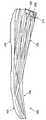
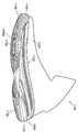
도 1a 내지 도 3b의 밑창 구조체(100, 200, 300) 모두는 비교적 균일한 형상을 갖는 3개 내지 5개의 개별 파형부 구조체를 다양한 영역에 걸쳐서 갖는 파형부 구조체를 나타내지만, 이것은 필수 조건은 아니다. 다른 예로서, 도 4는 파형부 구조체(402)가 수직 또는 상하 방향으로 배향된 3개의 파형부를 포함하는 다른 예시적인 밑창 구성요소(400)의 일부분을 도시한다. 도 4의 도면은 본 예시적인 파형부 구조체(402)의 바깥쪽 측면도를 도시하지만, 유사한 구조체가 예를 들어 밑창 구성요소(400)의 안쪽 측부 상에 및/또는 밑창 구성요소(400)의 후방 힐 영역에 제공될 수 있다. 본 예시적인 파형부 구조체(402)는 도 4에 도시된 바와 같이 폼 중창 구성요소(예를 들면, 상기에서 설명된 구성요소(102, 202, 302)와 유사함)에 제공될 수 있거나, 도 1a 내지 도 3b와 관련하여 상기에서 설명된 구성요소(104, 204, 304)와 유사한 폴리머 폼 보호 구성요소 및/또는 구성요소들과 같은 보호 구성요소에 제공될 수도 있다. 또한, 도 4에는 밑창 구성요소(400)의 힐 영역만이 도시되어 있지만, 본 기술분야에 숙련된 자는, 본 개시내용의 이점을 고려해 볼 때, 본 발명으로부터 벗어남이 없이, 착용자 발(또는 그것의 임의의 부분)의 전체 발바닥 표면을 지지하기 위한 밑창 구성요소가 제공될 수 있다는 것을 용이하게 이해할 것이다.Although all of the
도 4의 파형부 구조체(402)는 파형부의 형상에 있어서 도 1a 내지 도 3b에 대하여 상기에서 설명된 다른 파형부 구조체의 일부와 상이하다. 보다 구체적으로는, 도 4에 도시된 바와 같이, 본 예시적인 파형부 구조체(402)의 중앙 파형부(402b)는 상방 및 하방 방향 모두로 오목하다(또는 외측으로 팽창함). 도 4에 도시된 바와 같이, 중앙 파형부(402b)와 상단 파형부(402a) 사이의 개재 영역(404a)의 바닥 골은 오목한 상방 방향으로 만곡되고, 그에 따라 그 만곡부의 높은 지점이 중앙측 힐 영역에 있다. 유사하게, 중앙 파형부(402b)와 바닥 파형부(402c) 사이의 개재 영역(404b)의 바닥 골은 오목한 하방 방향으로 만곡되고, 그에 따라 그 만곡부의 하측 지점이 중앙측 힐 영역에 있다. 이러한 구성 때문에, 상단 파형부(402a)는 상방 방향으로 만곡되도록 형성되어 있고, 그 만곡부의 상측 최고 지점이 도 4에 도시된 배열에서 상단 파형부(402a)의 중앙 영역에 위치된다. 유사하게, 바닥 파형부(402c)는 하방 방향으로 만곡되도록 형성되어 있고, 그 만곡부의 하측 최저 지점이 도 4에 도시된 배열에서 바닥 파형부(402c)의 중앙 영역에 위치된다. 이것은 도 1a 내지 도 3b에 도시된 파형부 구조체의 적어도 일부와 비교하여 다소간의 보다 구상인(bulbous) 형상을 전체 파형부 구조체(402)에 제공한다.The
특히, 파형부 구성(402)은 도 1a 내지 도 1f에 도시된 파형부 구조체에서의 보다 단차형인 측벽과 비교하여 보다 매끄러운 측벽(도 2a 내지 도 3b의 파형부 구조체도 마찬가지임)을 갖는다. 또한, 도 2a 내지 도 4의 파형부 구성은 뾰족한 코너부로서 형성된 개별 파형부의 외측 리지를 갖는다. 그러나, 본 발명으로부터 벗어남이 없이, 이들 측벽 및/또는 코너부에 대한 다른 구조적 옵션이 가능하다.In particular, the
도 5, 도 6 및 도 7은 본 발명의 다른 예에 따른 밑창 구조체(500, 600, 700)를 포함하는 신발류 물품(550, 650, 750)의 다양한 다른 예의 측면도를 도시한다. 도 5는 농구화(650)를 도시하고, 도 6은 런닝화(650)를 도시하고, 도 7은 크로스 트레이닝화(750)를 도시한다. 밑창 구조체(500, 600, 700)는 각각 갑피(552, 652, 752)와 결합되어 전체 신발류 구조체(550, 650, 750)를 제공한다. 갑피(552, 652, 752)는 본 기술분야에 알려지고 사용되는 바와 같은 통상의 방식을 포함하여, 본 발명으로부터 벗어남이 없이 임의의 원하는 방식으로 각자의 밑창 구조체(500, 600, 700)와 결합될 수 있다. 일부의 보다 특정된 예로서, 갑피(552, 652, 752) 및 밑창 구조체(500, 600, 700)는 접착제 또는 시멘트에 의해, 기계적 커넥터에 의해, 스티칭(stitching) 또는 재봉에 의해, 및/또는 다른 연결 기술에 의해 서로 결합될 수 있다.5, 6, and 7 show side views of various other examples of
도 5 내지 도 7의 신발류 구조체(500, 600, 700)를 추가로 설명할 때, 예시적인 갑피의 다양한 특징(갑피(552, 652, 752)의 잠재적인 특징을 포함함)이 설명될 것이다. 이러한 설명은 도 1a 내지 도 4의 밑창 구조체(100, 200, 300, 400)와 결합될 수 있는 갑피의 예를 포함하는, 본 발명의 적어도 일부의 예에 따른 신발류 구조체에 포함될 수 있는 갑피의 특징의 예를 포함한다. 도 5 내지 도 7의 밑창 구조체(500, 600, 700)는 대체로 유사한 구조를 갖기 때문에, 이들 밑창 구조체(500, 600, 700)의 일부 차이점이 도 5 내지 도 7과 관련하여 설명될 것이다. 그 후에, 도 5 내지 도 7의 밑창 구조체(500, 600, 700)의 부품 및 구성의 보다 상세한 특징은 도 8a 내지 도 8f와 관련하여 보다 상세하게 설명될 것이다.When further describing the
본 발명에 따른 신발류 구조체(550, 650, 750)의 물품을 위한 갑피(552, 652, 752)는, 시멘트 또는 접착제의 사용을 통한 방식, 기계적 커넥터의 사용을 통한 방식, 및/또는 융착(fusing) 기술(예를 들면, 핫 멜트 재료 등의 용융 또는 융착 접합)을 통한 방식을 포함하여, 신발류 분야에 알려지고 사용되는 바와 같은 통상의 방식을 포함하는 임의의 원하는 방식으로 서로 결합될 수 있는 하나 또는 다수의 구성요소 부품 구성물을 구성할 수 있다. 일부의 제작 기술의 비제한적인 예가 하기에서 보다 상세하게 설명될 것이다.
갑피(552, 652, 752)는 본 발명으로부터 벗어남이 없이 임의의 원하는 재료 및/또는 재료들의 조합으로 제조될 수 있다. 예를 들면, 갑피(552, 652, 752)는 다층 구성물을 포함할 수 있으며, 다양한 층이 전체 갑피 영역의 모든 부분 또는 일부 부분을 덮는다. 일부의 보다 특정된 예에서, 갑피(552, 652, 752)는 (예를 들면, 발과의 편안한 접촉을 위한) 내부 직물(fabric) 또는 섬유층 및 외부 "외피(skin)"층(예를 들면, 특정 영역에서 보다 양호한 지지를 제공하기 위해, 특정 영역에서 내마모성 또는 내마멸성을 제공하기 위해, 원하는 미관성을 제공하기 위해 열가소성 폴리에틸렌 필름으로 제조됨)에 의해 적어도 일부 영역에서 덮이고 및/또는 샌드위치되는 중간 메시층을 포함할 수 있다. 내부 직물 또는 섬유층, 메시층, 및/또는 외피층의 어떠한 것도 갑피(552, 652, 752)의 전체 표면을 덮도록 연장될 필요는 없다. 오히려, 다양한 층의 위치(들)는 예를 들어 통기성을 향상시키기 위해, 가요성을 향상시키기 위해, 상이한 심미적 외관(아래에 놓인 메시 재료로부터 "로고(LOGO)" 또는 다른 디자인 특징부를 생성하기 위해 외피층에 있는 개구부 등)을 제공하기 위해, 특정 영역에서 외피층을 생략함으로써, 갑피(552, 652, 752)의 특성을 제어하도록 선택될 수도 있다. 또한, 본 기술분야에 알려진 바와 같이, 갑피(552, 652, 752)는 발목 개구부를 형성할 수도 있으며, 이러한 발목 개구부 주위로, 원한다면, 편안함-향상 폼 또는 직물 링이 제공될 수도 있다. 갑피(552, 652, 752)의 바닥면은 갑피 재료의 안쪽 측부와 바깥쪽 측부를 연결하는 내부 스트로벨(strobel) 부재(예를 들면, 스트로벨 부재는 갑피의 안쪽 및 바깥쪽 측부 에지에 재봉될 수도 있음)를 포함하여 갑피(552, 652, 752)를 폐쇄시킬 수 있다. 밑창 구조체(500, 600, 700)는 예를 들어 시멘트 또는 접착제, 스티칭 또는 재봉, 기계적 커넥터 등을 사용하여, 스트로벨 및 그 바닥 에지에서 갑피(552, 652, 752)와 결합될 수 있다.
다층 갑피 구성물은 신발류 분야에 공지되고 사용되는 바와 같은 통상의 방식을 포함하여, 본 발명으로부터 벗어남이 없이 임의의 원하는 방식으로 제조될 수도 있다. 예를 들면, 원한다면, 외피층은 통상의 방식으로 접착제 또는 핫 멜트 재료를 사용하여, 예를 들어 열 및/또는 압력의 인가에 의해, 아래에 놓인 메시층(또는 다른 층)에 접착될 수도 있는 "비-재봉" 타입 재료로 제조될 수도 있다. 추가적인 예로서, 원한다면, 외피층은 시멘트 또는 접착제에 의해 및/또는 재봉 시임(sewn seam)에 의해 아래에 놓인 메시층(또는 다른 층)과 결합될 수도 있다. 다른 추가적인 예로서, 원한다면, 갑피(552, 652, 752)(또는 그것의 부분들)는, 예를 들어 미국 특허 출원 공개 제2011/0088282호 및 미국 특허 출원 공개 제2011/0088285호에 개시된 바와 같이, 융착 기술을 사용하여 재료의 다양한 층을 접합함으로써 구성될 수도 있으며, 이들 특허문헌 각각은 전체적으로 본 명세서에 참조로 합체된다.The multi-layered top construction may be manufactured in any desired manner without departing from the present invention, including conventional manner as is known and used in the footwear field. For example, if desired, the outer skin layer may be adhered to the underlying mesh layer (or other layer), for example by application of heat and / or pressure, using an adhesive or hot melt material in a conventional manner. Non-sewn "type material. As a further example, if desired, the shell layer may be bonded to the underlying mesh layer (or other layer) by cement or adhesive and / or by sewn seam. As another further example, if desired, the upper 552, 652, 752 (or portions thereof) may be configured to be coupled to the upper 552, , Or by joining the various layers of material using fusing techniques, each of these patent documents incorporated herein by reference in its entirety.
갑피(552, 652, 752)는 원하는 위치에, 예를 들어 외부 외피층과 아래에 놓인 메시층 사이에 샌드위치된 다른 지지 요소를 포함할 수 있다. 예를 들면, 힐 카운터가 힐 영역에 제공되어 착용자의 힐에 대한 보다 많은 지지를 제공할 수 있다. 힐 카운터는, 존재한다면, PEBAX, TPU 또는 다른 폴리머 재료와 같은 강성의 얇은 플라스틱 재료로 제조될 수 있고, (예를 들면, 가요성, 통기성, 지지 특성을 제어하기 위해; 중량을 감소시키기 위해; 기타 등등을 위해) 하나 이상의 개구부를 포함할 수도 있다. 필요하거나 원한다면, 제5 중족골 헤드 등의 부근의 바깥쪽 측부 영역에서, (보호 및 내마모성을 제공하기 위해, 기타 등등을 위해) 전족부 또는 발가락 영역과 같은 신발(550, 650, 750)의 다른 영역에 추가적인 지지부가 제공될 수도 있다.The upper 552, 652, and 752 may include other support elements that are sandwiched at desired locations, for example, between the outer sheath layer and the underlying mesh layer. For example, a heel counter may be provided in the heel area to provide more support for the heel of the wearer. The heel counter, if present, can be made of a thin, rigid plastic material such as PEBAX, TPU, or other polymer material (e.g., to control flexibility, breathability, support properties; Or the like). ≪ / RTI > (550, 650, 750), such as a forefoot or toe area (for providing protection and abrasion resistance, etc.), in the outer lateral region of the vicinity of the fifth metatarsal head or the like Additional support may be provided.
본 발명의 적어도 일부 예에 따른 갑피(552, 652, 752)에 사용될 수 있는 다른 잠재적인 재료는 합성 가죽, 천연 가죽, 섬유, 이들 재료의 임의의 조합, 및/또는 상기에서 설명된 다른 재료 중 임의의 재료와 이들 재료의 임의의 조합 중 하나 이상을 포함한다. 다른 잠재적인 특징으로서, 원한다면, 갑피(552, 652, 752)의 적어도 일부 부분은 편물(knitting) 과정에 의해 형성될 수 있다. 선택적으로, 본 발명의 적어도 일부 예에서는, 갑피(552, 652, 752)의 적어도 대부분(또는 심지어 모두)이 편물 과정을 사용하여 형성될 수도 있다. 편물 섬유 구성요소는 경량이고 통기성이며 편안한 갑피 구성물을 제공하는데 사용될 수 있다.Other potential materials that may be used for
이제 도 5를 참조하여, 본 예시적인 신발류 구조체(550)의 추가적인 상세내용이 설명될 것이다. 본 예시적인 신발류 구조체(550)는 농구화이다. 갑피(552)는 가죽, 다층 융착-접합 재료, 또는 다른 재료로 제조된 구성물 및/또는 본 기술분야에 알려지고 사용되는 바와 같은 구성물을 포함하는 임의의 통상 농구화의 것과 같은 구성물을 가질 수 있다. 본 예의 밑창 구조체(500)는, 예를 들어 후방 힐 영역 주위의 전족부 바깥쪽 측부 영역으로부터 밑창 구조체(500)의 전족부 안쪽 측부 영역으로 밑창 구조체(500) 주위에서 연속적으로 연장되는 일련의 5개의 적층된 파형부를 포함하는, 상기에서 상세하게 설명된 바와 같이 도 1a 및 도 1f에 도시된 밑창 구조체(100)와 유사한 대체적인 외관을 갖는다. 본 예시적인 밑창 구조체(500)의 5개의 파형부 구성은 현재의 농구화에 공통인 바와 같이 다소 높은 힐 구조를 생성하기 때문에 농구화에 아주 적합하다.Referring now to FIG. 5, additional details of this
파형부 외관이 유사하지만, 도 5의 밑창 구조체(500)는 도 1a 내지 도 1f의 밑창 구조체(100)와 구성적으로 상당히 상이하다. 본 밑창 구조체(500)의 구성의 상세한 설명은 하기에서의 도 8a 내지 도 8f의 논의를 위해 보류되지만, 이 시점에서는, 밑창 구조체(500)의 노출된 후방 부분(504)이 중창 구성요소(502)의 일부분을 적어도 부분적으로 유지 및 수용하는 보호 요소를 구성한다라는 것이 적절하다. 후방 보호 구성요소(504)는 상기에서 설명된 다양한 보호 구성요소(104, 204, 304)와 같은 재료(예를 들면, 그 외측벽 에지 상에 하나 이상의 파형부 구조체가 형성된 폴리머 폼 재료를 포함함)로 제조될 수도 있다. 본 예에서의 밑창 구조체(500)의 전방 부분(502)은, 전술한 바와 같이, (동일하거나 유사한 재료를 포함하여) 경량의 중창 구성요소(102, 202, 302)와 유사할 수 있는 경량의 폼 중창 재료(502)의 노출된 부분을 구성한다. 중창 구성요소(502)가 여전히 착용자 발의 발바닥 표면의 모두 또는 실질적으로 모두를 지지하도록 연장될 수 있지만, 본 도시된 예에서는, 경량의 중창 구성요소(502)의 적어도 일부 및 선택적으로 대부분이 보호 구성요소(504) 내에 수용된다. 이러한 방식으로, 신발류 구조체(550)의 후방에서, 보호 구성요소(504)는 경량의 폼 중창 구성요소(502)를 위한 케이지 또는 캐리어로서 작용한다. 폼 중창 구성요소(502)는 하기에서 보다 상세하게 설명되는 바와 같이 보호 구성요소(504)의 전방 (개방) 단부의 외측으로 연장된다.The outline of the corrugated portion is similar, but the
이제 도 6을 참조하여, 본 예시적인 신발류 구조체(650)의 추가적인 상세내용이 설명될 것이다. 본 예시적인 신발류 구조체(650)는 런닝화이다. 갑피(652)는 다층 융착-접합 재료, 섬유, 메시, 편물 재료 또는 다른 재료로 제조된 구성물 및/또는 본 기술분야에 알려지고 사용되는 바와 같은 구성물을 포함하는 임의의 통상 런닝화의 것과 같은 구성물을 가질 수 있다. 본 예의 밑창 구조체(600)는, 예를 들어 밑창 구조체(600)의 후방 힐 영역 주위로 연장되는 제1 일련의 적층된 파형부(610), 및 밑창 구조체(600)의 중족부 및 전족부 영역을 향해 힐 영역으로부터 전방으로 연장되는 엇갈림식 전방 파형부 시리즈(612)를 포함하는, 상기에서 상세하게 설명된 바와 같이 도 2a 및 도 2f에 도시된 밑창 구조체(200)와 유사한 대체적인 외관을 갖는다. 전방 파형부 시리즈(612)는 후방 힐 파형부 시리즈(610)의 파형부들 사이의 개재 영역에서 시작된다. 전방 파형부 시리즈(612)의 상단 파형부는 후방 힐 파형부 시리즈(610)의 상단 파형부 위에서 시작된다. 후방 힐 파형부 시리즈(610)는 힐-중족부간 영역에서, 예를 들어 전방 파형부 시리즈(612)의 개별 파형부 사이 또는 개별 파형부를 따르는 개재 영역에서 종단된다. 도 6이 바깥쪽 측면도만을 도시하고 있지만, 본 밑창 구조체(650)의 안쪽 측면도가 유사한 개재 파형부 구성을 가질 수도 있다.Referring now to FIG. 6, additional details of this
본 예시적인 런닝화(650)를 위한 밑창 구조체(600)는 도 2a 내지 도 2f의 밑창 구조체(200) 및 도 5의 밑창 구조체(500)보다 다소 짧고 프로파일이 낮다. 특히, 밑창 구조체(600)는 (도 2a 내지 도 2f에 도시된 5개의 파형부 대신에) 후방 힐 영역에 3개의 수직으로 적층된 파형부(610), 및 힐 파형부(610)와 엇갈려 있는 3개의 수직으로 적층된 전방 파형부(612)를 포함한다. 요구되지는 않지만, 이러한 파형부의 개수 감소는 밑창 구조체(600)의 힐 영역에서 다소 작은 수직 높이를 제공한다.The
또한, 도 5의 밑창 구조체(500)와 마찬가지로, 밑창 구조체(600)의 노출된 후방 부분(604)은 경량의 폼 중창 구성요소(602)의 일부분을 적어도 부분적으로 유지 및 수용하는 보호 요소를 구성한다. 후방 보호 구성요소(504)는 상기에서 설명된 다양한 보호 구성요소(104, 204, 304)와 같은 재료(예를 들면, 그 외측벽 에지 상에 하나 이상의 파형부 구조체가 형성된 폴리머 폼 재료를 포함함)로 제조될 수도 있다. 본 예에서의 밑창 구조체(600)의 전방 부분(602)은, 전술한 바와 같이, (동일하거나 유사한 재료를 포함하여) 경량의 중창 구성요소(102, 202, 302)와 유사할 수 있는 경량의 폼 중창 재료(602)의 노출된 부분을 구성한다. 중창 구성요소(602)가 여전히 착용자 발의 발바닥 표면의 모두 또는 실질적으로 모두를 지지하도록 연장될 수 있지만, 본 예시적인 구조체(600)에서는, 경량의 중창 구성요소(602)의 적어도 일부 및 선택적으로 대부분이 보호 구성요소(604) 내에 수용된다. 이러한 방식으로, 신발류 구조체(650)의 후방에서, 보호 구성요소(604)는 경량의 폼 중창 구성요소(602)를 위한 케이지 또는 캐리어로서 작용한다. 폼 중창 구성요소(602)는 하기에서 보다 상세하게 설명되는 바와 같이 보호 구성요소(604)의 전방 (개방) 단부의 외측으로 연장된다.5, the exposed
도 6(예를 들면, 런닝화(650)가 수평 접촉면 상에 배향되어 있음)에 도시된 수직 방향에 대해서, 힐 및/또는 중족부 영역은 후방 힐 파형부 시리즈(610) 및 전방 파형부 시리즈(612)로부터의 인터위빙형 파형부를 포함한다. 다시 말해서, 밑창 구조체(600)의 힐 및/또는 중족부 영역의 적어도 일부 부분에서 수직 방향으로 이동함(예를 들면, 라인(614)으로 도시됨)에 따라, 후방 힐 파형부 시리즈(610)의 개별 파형부의 표면들 사이에 위치된 전방 파형부 시리즈(612)의 개별 파형부의 표면들과 만난다. 이러한 적층형 및/또는 인터위빙형 일련의 파형부는 이러한 힐/중족부 영역에 추가 지지를 제공하고 런닝화 밑창에 대한 양호한 지지를 제공한다.For the vertical direction shown in Figure 6 (e.g., the running
도 7은 트레이닝화(750)를 도시한다. 갑피(752)는 융착-접합 재료, 섬유, 메시, 편물 재료 또는 다른 재료로 제조된 구성물 및/또는 본 기술분야에 알려지고 사용되는 바와 같은 구성물을 포함하는 임의의 통상 트레이닝화의 것과 같은 구성물을 가질 수 있다. 본 예의 밑창 구조체(700)는 하기에서 보다 상세하게 설명되는 바와 같이 개재 파형부를 가지는 구성을 갖는다. 도 5의 밑창 구조체(500)와 마찬가지로, 밑창 구조체(700)의 노출된 후방 부분(704)은 중창 구성요소(702)의 일부분을 적어도 부분적으로 유지 및 수용하는 보호 요소를 구성한다. 후방 보호 구성요소(704)는 상기에서 설명된 다양한 보호 구성요소(104, 204, 304)와 같은 재료(예를 들면, 그 외측벽 에지 상에 파형부 구조체들이 형성된 폴리머 폼 재료를 포함함)로 제조될 수도 있다. 본 예에서의 밑창 구조체(700)의 전방 부분(702)은, 전술한 바와 같이, (동일하거나 유사한 재료를 포함하여) 경량의 중창 구성요소(102, 202, 302)와 유사할 수 있는 경량의 폼 중창 재료(702)의 노출된 부분을 구성한다. 중창 구성요소(702)가 여전히 착용자 발의 발바닥 표면의 모두 또는 실질적으로 모두를 지지하도록 연장될 수 있지만, 본 예시적인 구조체(700)에서는, 경량의 중창 구성요소(702)의 적어도 일부 및 선택적으로 대부분이 보호 구성요소(704) 내에 수용된다. 이러한 방식으로, 신발류 구조체(750)의 후방에서, 보호 구성요소(704)는 경량의 폼 중창 구성요소(702)를 위한 케이지 또는 캐리어로서 작용한다. 폼 중창 구성요소(702)는 하기에서 보다 상세하게 설명되는 바와 같이 보호 구성요소(704)의 전방 (개방) 단부의 외측으로 연장된다.FIG. 7 shows
본 예시적인 밑창 구조체(700)에서, 보호 구성요소(704)의 후방 힐 영역 및 중창 폼 구성요소(702)의 전방 발가락 영역 모두는 수직으로 적층된 3개의 파형부 구조체(힐 파형부가 전족부 파형부보다 다소 깊음)를 포함한다. 그러나, 적어도 트레이닝화(750)의 바깥쪽 측부를 따르는 중족부-전족부간 영역에는, 다양한 다른 타입의 지지 특징부가 제공된다(그렇지만, 원한다면, 유사한 구조체가 안쪽 측부 상에 제공될 수 있음). 도 7에서 수직 방향으로 이동함에 따라, 제1 지지 리브 또는 요소(710)가 (본 예에서는, 폼 중창 구성요소(702)에 있어서) 밑창 구조체(700)의 바깥쪽 측부의 바닥을 따라 제공된다. 제1 지지 리브 또는 요소(710)는 밑창 구조체(700)의 제5 중족골 지지 영역에 근접하여 그로부터 수직 하방에 위치된다. 제2 지지 리브 또는 요소(712)가 제1 지지 리브 또는 요소(710)로부터 다소 후방 및 상방에 제공된다. 제2 지지 리브 또는 요소(712)는 본 예시적인 구조체(700)에서 폼 중창 구성요소(702)와 보호 구성요소(704) 사이의 결합부를 브리징(bridging)하고, 밑창 구조체(700)의 중족부 또는 아치형 영역에서 더 뾰족해진다. 제2 지지 리브 또는 요소(712)는 제1 지지 리브 또는 요소(710)보다 대체로 긴 단부간 길이방향 치수를 가질 수 있다. 제3 지지 리브 또는 요소(714)가 제2 지지 리브 또는 요소(712)로부터 다소 전방 및 상방에 제공된다. 이러한 제3 지지 리브 또는 요소(714)의 적어도 대부분(및 잠재적으로 모두)은 폼 중창 구성요소(702)에 형성된다. 제3 지지 리브 또는 요소(714)는 제1 지지 리브 또는 요소(710)와 수직으로 중첩하고, 밑창 구조체(700)의 제5 중족골 헤드 지지 영역에 근접하여 그로부터 수직 하방에 위치된다. 이러한 제3 지지 리브 또는 요소(714)는 제1 지지 리브 또는 요소(710)보다 짧은 (단부간) 길이방향 치수를 가질 수 있다. 제4 지지 리브 또는 요소(716)는 제3 지지 리브 또는 요소(714)로부터 다소 후방 및 상방에 제공된다. 이러한 제4 지지 리브 또는 요소(716)는 또한 중창 구성요소(702)와 보호 구성요소(704) 사이의 결합부를 브리징하지만, 그 대부분이 중창 구성요소(702)에서 제2 지지 리브 또는 요소(712)의 전방에 위치된다. 제5 지지 리브 또는 요소(718)가 제4 지지 리브 또는 요소(716)로부터 다소 전방 및 상방에 제공된다. 이러한 제5 지지 리브 또는 요소(718)의 적어도 대부분(및 잠재적으로 모두)은 폼 중창 구성요소(702)에 형성된다. 제5 지지 리브 또는 요소(718)는 제1 지지 리브 또는 요소(710) 및 제3 지지 리브 또는 요소(714)와 수직으로 중첩하고, 밑창 구조체(700)의 제5 중족골 헤드 지지 영역에 근접하여 위치된다. 제5 지지 리브 또는 요소(718)는 제1 지지 리브 또는 요소(710) 및/또는 제3 지지 리브 또는 요소(714)보다 짧은 길이방향 치수를 가질 수 있다.In this exemplary
따라서, 제1 지지 리브 또는 요소(710), 제2 지지 리브 또는 요소(714), 제3 지지 리브 또는 요소(714), 제4 지지 리브 또는 요소(716), 및 제5 지지 리브 또는 요소(718)는 후방 힐 보호 구성요소(704) 및 전방 폼 중창 구성요소(702)에서의 파형부 구조체들 사이의 파형부 구조체의 불연속부를 생성한다. 이들 지지 리브 또는 요소(710, 712, 714, 716 및/또는 718)는, 예를 들어 착용자 발의 제5 중족골 헤드 근방의 영역에 있어서, 본 밑창 구조체(700)의 바깥쪽 중족부 및/또는 전족부 영역에 대한 추가적인 지지를 제공한다. 이것은, 발의 외측을 밀 때, 예를 들어 급격한 터닝(turning) 또는 커팅(cutting) 동작을 할 때와 같은 트레이닝 활동 동안에 착용자에 대한 추가적인 지지를 제공한다.Thus, the first support rib or
다른 특정 구조가 가능하지만, 본 도시된 예에서, 지지 리브 또는 요소(710, 712, 714, 716, 718)는 밑창 구조체(700)의 측면으로부터 외측으로 연장되는 융기형 피라미드식 구조로서 형성된다. 지지 리브 또는 요소(710, 712, 714, 716, 718)는 상기에서 설명된 다양한 다른 도면에 도시된 인터위빙형 파형부 구조체와 다소 유하게 배향될 수 있다. 보다 구체적으로는, 도 7에 도시된 바와 같이, 지지 리브 또는 요소(712 및 716)는 지지 리브 또는 요소(710, 714 및 718)들 사이의 개재 영역에서 시작된다. 지지 리브 또는 요소(710, 712, 714, 716, 718)는 또한 지지 리브 또는 요소의 전방 및/또는 후방에 위치된 파형부들 사이의 개재 영역에서 시작될 수도 있다. 특히, 지지 리브 또는 요소(712, 716 및 718)의 외측으로 연장되는 피크는 상단 전방-바닥 후방 방향으로 실질적으로 정렬한다. 또한, 지지 리브 또는 요소(710, 714 및 718)의 외측으로 연장되는 피크는 상단으로부터 하단으로 수직 방향으로 실질적으로 정렬한다.Support ribs or
도 7의 지지 리브 또는 요소 구조체는 단지 바깥쪽 및/또는 안쪽 측부 지지를 제공하기 위한(및/또는 트레이닝화(700)의 지지 특징을 변경하거나 제어하기 위한) 구조체의 예를 구성한다. 서로에 대해서 상이한 개수의 리브, 상이한 배열의 리브, 상이한 형상의 리브, 및/또는 상이한 상대 배향의 리브를 포함하는 다른 지지 변경 구성이 본 발명으로부터 벗어남이 없이 사용될 수도 있다. 또한, 원한다면, 인접한 파형부 구조체 사이에 단순 갭이 제공되어, 예를 들어 갭에서 지지 또는 느낌을 변경할 수 있다. "갭"은 파형부 구조체들 사이의 폼 재료 또는 매끄러운 폼 재료 내의 실제 간격(actual spacing)을 포함할 수 있다.The supporting rib or element structure of Figure 7 constitutes an example of a structure to provide only outer and / or inner side support (and / or to modify or control the support features of the training 700). Other support changing configurations may be used without departing from the invention, including a different number of ribs, ribs of different arrays, ribs of different shapes, and / or ribs of different relative orientations with respect to each other. Also, if desired, a simple gap may be provided between adjacent corrugated sub-structures to change the support or feel in the gap, for example. The "gap" may include the actual spacing in the foam material or the smooth foam material between the corrugated structures.
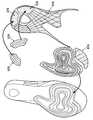
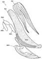
도 5 내지 도 7의 밑창 구조체(500, 600, 700)의 하나의 예시적인 구성이 도 8a 내지 도 8f와 관련하여 보다 상세하게 설명된다. 도 8a는 후방 보호 구성요소(804), 및 이 보호 구성요소(802)의 전방으로 그리고 그 자유 단부의 외측으로 연장되는 폼 중창 구성요소(802)를 포함하는 예시적인 밑창 구조체(800)의 저면 사시도를 도시한다. 도 8a는 보호 구성요소(804) 및 폼 중창 구성요소(802)가 서로 끼워맞춰지는 것을 도시하지만, 예를 들어 접착제 또는 시멘트를 사용하여 서로에 대해 고정되기 전을 도시한다. 도 8b는 서로 분리되어 있는 이들 2개의 부품의 저면도를 도시하고, 도 8c는 서로 분리되어 있는 이들 2개의 부품의 평면도를 도시한다. 이들 도면으로부터 알 수 있는 바와 같이, 보호 구성요소(802)는 폼 중창 구성요소(802)의 후방 부분을 수용하는 케이지 또는 캐리어로서 작용한다. 폼 중창 구성요소(802)는 착용자 발의 발바닥 표면의 모두 또는 실질적으로 모두를 지지하기 위한 상측 지지면(802a)을 갖는다(그렇지만, 원한다면, 보호 구성요소(804)가 또한 착용자 발의 발바닥 표면의 적어도 일부 부분을 직접 지지하기 위한 표면을 제공할 수도 있음). 보호 구성요소(804)의 전방 자유 단부 외측으로 연장되는 것에 부가하여, 폼 중창 구성요소(802)는 보호 구성요소(804)의 바닥면에 형성된 힐 개구부(806)를 통해 노출된다. 이러한 바닥 개구부(806)를 제공하는 것에 의해, 중량을 가볍게 할 수 있는 동시에, 전체 밑창 구조체(800)의 가요성 특성을 제어 및 변경할 수 있게 한다.One exemplary configuration of the
본 예시적인 구조체(800)에서, 폼 중창 구성요소(802)는 구성요소(102, 202, 302)와 관련하여 상기에서 설명된 타입의 경량의 폼 재료를 포함하여, 본 발명으로부터 벗어남이 없이 임의의 원하는 폼 재료(또는 폼 재료의 조합)로 제조될 수 있다. 선택적으로, 원한다면, 폼 중창 구성요소(802)에는 하나 이상의 유체 충전식 블래더, 기계적 충격 흡수 구조체, 및/또는 충격력 감쇠를 제공하기 위한 다른 구조체가 매립 또는 포함될 수도 있다. 그러나, 본 도시된 예에서는, 폼 중창 구성요소(802)는 폼 재료의 단일의 중실 피스, 바람직하게는 상기에서 설명된 경량이고 및/또는 덜 조밀한 폼 재료 중 하나를 구성한다.In this
본 도시된 예시적인 밑창 구조체(800)의 보호 구성요소(804)는 또한 신발류 분야에서 중창 재료로서 알려지고 사용되는 바와 같은 통상의 폴리머 폼 재료를 포함하는 폴리머 폼 재료를 구성할 수도 있다. 일부의 보다 특정된 예로서, 보호 구성요소(804)는 폴리우레탄 폼, 에틸비닐아세테이트("EVA") 폼, 파일론, 또는 다른 알려진 중창 폼 또는 재료로 제조될 수도 있다. 본 발명에 따른 일부 예시적인 구조체에서, 보호 구성요소(804)에 사용되는 폴리머 폼 재료는 폼 중창 구성요소(802)에 사용되는 폼 재료보다 무겁고, 조밀하며 및/또는 내구성있는 폼 재료(예를 들면, 내마모성, 내마멸성 등)이다.The
또한 도 8a 내지 도 8c에 도시된 바와 같이, 보호 구성요소(804)의 폴리머 폼 재료는 적어도 그 주변 에지의 부분(들) 주위에 형성된 파형부 구조체를 포함할 수 있다. 보다 구체적으로는, 도 8a 내지 도 8c는 보호 구성요소(804)(도 5 내지 도 7의 보호 구성요소와 같음)가 파형부 구조체를 포함하는 외측 쉘을 구성할 수 있으며, 외측 쉘은 바깥쪽 측벽(804a); 안쪽 측벽(804b); 안쪽 측벽(804b) 및 바깥쪽 측벽(804a)을 연결하는 후방 힐 벽(804c); 및 안쪽 측벽(804b), 바깥쪽 측벽(804a) 및 후방 힐 벽(804c)을 연결하는 바닥 벽(804d)을 포함한다. 본 발명의 적어도 일부 예에서, 보호 구성요소(804)의 폴리머 폼 재료의 파형부 구조체는 바깥쪽 측벽(804a)의 적어도 일부분, 후방 힐 벽(804c), 및 안쪽 측벽(804b)의 적어도 일부분의 외부면 주위로 연속적으로 연장된다. 보호 구성요소(804)의 폴리머 폼 재료의 파형부 구조체는 또한 상기에서 설명된 인터위빙형 파형부, 지지 리브 또는 요소, 수직 리브, 갭, 및/또는 임의의 다른 파형부 구조체, 특징부 및/또는 옵션을 포함할 수도 있다.8A-8C, the polymeric foam material of
도 8a 내지 도 8c는 적어도 폼 중창 구성요소(802)의 힐 부분이 보호 구성요소(804)의 바깥쪽 측벽(804a), 안쪽 측벽(804b), 후방 힐 벽(804c) 및 바닥 벽(804d) 사이에 형성된 공간에 수용되는 것을 또한 도시한다. 폼 중창 구성요소(802)의 전족부 단부는 본 예시적인 구조체(800)에서 바깥쪽 측벽(804a)의 전방 단부 및 안쪽 측벽(804b)의 전방 단부를 지나서 연장된다. 폼 중창 구성요소(802)의 이러한 중족부 단부는 최종 밑창 구조체(800)에서 적어도 부분적으로 노출될 수 있다.8A-8C illustrate that at least the heel portion of the
적어도 도 7에 대해서 상기에서 설명된 바와 같이, 보호 구성요소(804)의 외부측 에지면 및 폼 중창 구성요소의 외부측 에지면 모두는 파형부 구조체를 포함할 수 있다. 예를 들면, 보호 구성요소(804)의 파형부 구조체는 밑창 구조체의 바깥쪽 측부-후방 힐-안쪽 측부 주위로 (연속적으로 또는 (예를 들면, 인터위빙형 파형부, 다른 지지부, 및/또는 다른 특징부로 인해) 불연속적으로) 연장된다. 추가적으로 또는 대안적으로, 폼 중창 구성요소(802)는 밑창 구조체(800)의 전방 발가락 영역 주위로 연장되는 파형부 구조체를 포함할 수도 있다. 본 특정의 도시된 예에서, 폼 중창 구성요소(802)의 파형부 구조체는 2개의 파형부 개재 영역에 의해 연결된 3개의 파형부 외측 리지를 포함한다.As described above with respect to FIG. 7 at least, both the outer side surface of the
구성요소(802 및 804) 모두가 파형부 구조체를 갖는 경우, 폼 중창 구성요소(802)의 파형부 구조체는 보호 구성요소(804)의 파형부 구조체와 연속하여 연장될 수 있거나 연장될 수 없다. 이들 파형부 구조체는, 본 발명으로부터 벗어남이 없이, 예를 들어 지지 리브 또는 다른 요소에 의해, 개재 파형부에 의해, 밑창 구조체 내의 갭에 의해, 매끄러운 폼 재료에 의해, 외부 플라스틱 또는 복합재 지지부에 의해, 전이 영역에 의해, 또는 기타 등등에 의해 중단될 수 있다. 파형부 구조체에서의 이러한 "중단부(interruption)"는, (예를 들면, 보다 자연스러운 운동 굽힘성을 지지하는 위치를 제공하기 위해) 밑창 구조체의 바깥쪽 전족부 영역 및 밑창 구조체의 안쪽 전족부 영역, (예를 들면, 커팅 또는 터닝 동작에 대한 추가 지지를 제공하기 위해) 밑창 구조체의 바깥쪽 전족부 영역, 및/또는 (예를 들면, 자연스러운 운동 가요성 특성을 포함하는 원하는 지지 및/또는 가요성을 제공하기 위해) 다른 원하는 위치와 같은 임의의 원하는 위치에 제공될 수 있다.If both
폼 중창 구성요소(802) 및/또는 보호 구성요소(804) 중 어느 하나 또는 모두의 바닥면에는 추가적인 구성요소가 제공될 수도 있다. 예를 들면, 사용 시에 지면과 접촉하는 밑창 구조체(800)의 적어도 일부 부분에 대해, 내마모성 및 내구성 특징을 향상시키기 위해, 내마멸성 또는 내마모성 재료가 이들 구성요소의 바닥면의 적어도 일부분에 적용될 수 있다. 도 8d는 보호 구성요소(804)의 바닥면에, 선택적으로는 보호 구성요소(804)의 힐 영역에 형성(예를 들어, 몰딩 또는 절단)된 리셉터클(822) 내에 적용될 수 있는 예시적인 바닥창 구성요소(820)를 도시한다. 도 8e는 폼 중창 구성요소(802)의 바닥면에, 선택적으로는 폼 중창 구성요소(802)의 전족부 영역(영역(826))에 형성(예를 들면, 몰딩 또는 절단)된 리셉터클 또는 다른 영역 내에 적용될 수 있는 예시적인 바닥창 구성요소(824)를 도시한다. 도 8f는 이들 부품, 및 이러한 부품이 서로 끼워맞춰지는 방법을 도시한다. 이들 바닥창 구성요소(820, 824)는 고무, 열가소성 폴리우레탄 등을 포함하여, 본 발명으로부터 벗어남이 없이 임의의 원하는 바닥창 재료(또는 바닥창 재료의 조합)로 제조될 수 있다. 추가적으로 또는 대안적으로, 바닥창 구성요소(820, 824) 중 하나 이상은 탈착가능한 클리트 구조체를 수용하기 위한 클리트 구조체 또는 리셉터클을 구성할 수도 있다.Additional components may be provided on the bottom surface of any or all of the
도 9는 본 발명의 일부 예에 따른 다른 예시적인 밑창 구조체(900)의 분해도를 제공한다. 이러한 밑창 구조체(900)에서, (예를 들어 상기에서 설명된 타입의) 경량의 폼 중창 구성요소(902)는 착용자 발의 발바닥 표면의 모두 또는 실질적으로 모두를 지지하기 위한 지지면(902a)을 포함한다. 폼 보호 구성요소(904)(선택적으로는 임의의 원하는 타입의 파형부 구조체를 포함함)는 적어도 중창 구성요소(902)의 측부 주위로 연장되고, (본 예에서는, 후방 힐 영역 주위의 바깥쪽 중족부 또는 전족부 영역으로부터 안쪽 중족부 또는 전족부 영역까지) 중창 구성요소(902)의 그러한 부분을 수용하기 위한 케이지 또는 캐리어로서 작용한다. 복수의 바닥창 보호 구성요소(906a, 906b, 906c, 906d)가 폼 중창 구성요소(902)의 바닥(및/또는, 보호 구성요소(904)가 밑창 구조체(900)의 외부 바닥면에 노출되는 경우, 보호 구성요소(904)의 바닥)의 다양한 영역을 보호하도록 제공된다. 본 도시된 예에서, 바닥창 구성요소(906a)는 폼 중창 구성요소(902)(및/또는 보호 구성요소(904))의 한쪽 힐 측부를 보호하고, 바닥창 구성요소(906b)는 폼 중창 구성요소(902)(및/또는 보호 구성요소(904))의 후방 힐 영역을 보호하며, 바닥창 구성요소(906c)는 폼 중창 구성요소(902)(및/또는 보호 구성요소(904))의 다른쪽 힐 측부를 보호한다. 전족부 영역에 있는 비교적 큰 바닥창 보호 구성요소(906d)는 폼 중창 구성요소(902)(및/또는 보호 구성요소(904))의 바닥의 전족부 영역의 모두는 아니더라도, 대부분을 덮는다. 이들 다양한 구성요소는 임의의 원하는 방식으로, 예를 들어 시멘트 또는 접착제에 의해, 기계적 커넥터에 의해, 또는 본 기술분야에 알려지고 사용되는 바와 같은 임의의 다른 방식으로 서로 결합될 수 있다. 이들 구성요소는 대응하는 부품에 대해 예를 들어 전술한 임의의 재료로 제조될 수도 있다. 또한, 도 9에 도시되고 상기에서 설명된 임의의 개별 구성요소는 본 발명으로부터 벗어남이 없이 하나 이상의 별개 부품으로 제조될 수도 있다.Figure 9 provides an exploded view of another exemplary
도 5 내지 도 9는 경량의 중창 구성요소가 힐 및/또는 중족부 영역에서 보호 구성요소에 의해 적어도 부분적으로 덮이는(또한, 밑창 구조체의 전족부 영역에서 노출되도록 외측으로 연장되는) 밑창 구조체를 도시하고 있지만, 다른 구성이 본 발명으로부터 벗어남이 없이 가능하다. 예를 들면, 원한다면, 경량의 중창 구성요소 및 보호 구성요소의 노출된 부분은 본질적으로 도 5 내지 도 9의 구조체에서 단부를 "플립-플롭(flip-flop)"으로 형성할 수 있고, 그에 따라 경량의 중창 구성요소는 전족부 및/또는 중족부 영역에서 보호 구성요소에 의해 덮인다(또한, 밑창 구조체의 힐 영역에서 노출되도록 외측으로 연장됨). 경량의 중창 구성요소와 보호 구성요소 사이의 크기, 형상 및/또는 결합 영역에 대한 변경은 또한 본 발명으로부터 벗어남이 없이 폭넓게 변화될 수도 있다.5 to 9 show a sole structure in which a lightweight midsole component is at least partially covered by a protective component in the heel and / or midsole region (and which extends outward to be exposed in the forefoot region of the sole structure) However, other configurations are possible without departing from the present invention. For example, if desired, the lightweight midsole component and the exposed portion of the protective component can essentially form an end "flip-flop" in the structure of Figures 5 to 9, The lightweight midsole component is covered by a protective component in the forefoot and / or midfoot region (and also extends outward to be exposed in the heel region of the sole structure). Modifications to the size, shape and / or engagement area between the lightweight midsole component and the protective component may also vary widely without departing from the invention.
도 10a 및 도 10b는 본 발명의 적어도 일부 예에 따른 밑창 구조체에 포함될 수 있는 추가적인 특징부를 도시한다. 도 10a는 상기에서 상세하게 설명된 바와 같이, 경량의 중창 구성요소(1002)의 바닥면(1002a)을 도시한다. 본 예시적인 경량의 중창 구성요소(1002)의 바닥면(1002a)은 중창 구성요소(1002)의 다양한 위치에 복수의 확장 또는 "구상(bulbous)" 영역을 포함한다. 하나의 구상 영역(1004a)은 중창 구성요소(1002)의 후방 힐 영역에 제공되고, 예를 들어 착용자가 걸음을 내딛거나 점프를 착지할 때에 대해, 추가적인 충격력 감쇠 및/또는 편안하고 부드러운 느낌을 제공한다. 추가적인 구상 영역이 밑창 구조체(1000)의 전족부 영역에 제공된다. 보다 구체적으로는, 구상 영역(1004b)이 예를 들어 중창 구성요소(1002)의 바깥쪽 측부 상의 제5 중족골 헤드 영역 아래에 제공된다. 제3 구상 영역(1004c)은 구상 영역(1004b)의 중심에 대해 다소 전방 및 안쪽으로 중심설정되어(예를 들면, 밑창의 제5 중족골 헤드 지지 영역 아래(즉, 엄지발가락의 중족골 헤드 영역 아래)에 위치된 바깥쪽 측부에) 위치된다. 제4 구상 영역(1004d)은 제3 구상 영역(1004c)의 전방에(예를 들면, 엄지발가락 및/또는 인접한 발가락 아래에 위치된 바깥쪽 측부에) 위치된다.10A and 10B illustrate additional features that may be included in the sole structure according to at least some examples of the present invention. Figure 10a shows the
본 예시적인 구조체(1002)에서의 구상 영역(1004a 내지 1004d)은, 달리기(또는 걷기), 걸음 내딛기 또는 점프 착지, 점프 개시 등과 같은 특정 활동 동안에 착용자 발 아래에서의 추가적인 충격력 감쇠 및/또는 편안하고 부드러운 느낌을 제공하도록 배열된다. 전형적인 걸음 사이클(step cycle) 동안, 런너(runner)는 발의 바깥쪽 힐 측부를 향해 걸음을 내딛는다. 구상 영역(1004a)은 본 중창 구성요소(1002)의 후방 힐 영역에 제공되어 이러한 힐의 부딪침 시에 추가적인 충격력 감쇠 및/또는 편안하고 부드러운 느낌을 제공한다. 걸음을 계속함에 따라, 발이 전방으로 롤링(rolling)하고 밑창의 바깥쪽 측부 에지가 지면과 접촉한다. 구상 영역(1004b)은 본 중창 구성요소(1002)의 바깥쪽 측부 영역(새끼발가락 아래)에 제공되어 걸음 사이클에서의 이러한 때에 추가적인 충격력 감쇠 및/또는 편안하고 부드러운 느낌을 제공한다. 발이 전방으로 롤링을 계속함에 따라, 발은 또한 안쪽 측부를 향해 내측으로 롤링하기 시작하고, 결국 런너는 제1 중족골 헤드 영역 및/또는 엄지발가락(및 아마도 인접한 발가락)을 사용하여 지면을 밀게 된다. 구상 영역(1004c, 1004d)은 본 중창 구성요소(1002)의 안쪽 전족부 측부 영역(발의 공형상부(ball) 및/또는 엄지발가락 영역 아래)에 제공되어 걸음 사이클에서의 이러한 때에 추가적인 충격력 감쇠 및/또는 편안하고 부드러운 느낌을 제공한다.The
도 10b는 도 10a에 대하여 상기에서 설명된 타입의 중창 구성요소(1002)가 그 내에 포함되는 밑창 구조체(1000)의 바닥면(1000a)의 예시를 도시한다. 도면에 도시된 바와 같이, 밑창 구조체(1000)의 바닥은 구상 영역(1004a 내지 1004d) 아래에 놓이는 트랙션 요소 및/또는 다른 특징부(예를 들면, 하기에서 보다 상세하게 설명되는 바와 같은 얇은 웨브형 보호 구성요소의 일부로서 형성됨)를 포함한다. 다양한 위치에서의 밑창 구조체(1000) 및 그러한 위치 위의 폼 재료의 구상 특성은 구상 영역(1004a 내지 1004d)에서 양호한 충격력 감쇠를 제공하는 것을 돕는다. 추가적으로 또는 대안적으로, 중창 구성요소(1002)의 폼 재료가 충분히 민감하게 반응한다면, 이들 구상 영역(1004a 내지 1004d)의 적어도 일부는 발에 대해 복원 에너지(return energy)를 제공할 수 있다(예를 들면, 충격력이 줄어들고(발이 다음 걸음을 위해 들어올려질 때) 폼 중창 구성요소(1002)가 원래 형상으로 복귀할 때 착용자의 발바닥 표면에 발 부상력(lifting force)을 가함).Figure 10B illustrates an example of the
4개의 별도 구상 영역이 설명되고 도 10a에 대하여 전술한 방식으로 이격되어 있지만, 이것은 필수 조건은 아니다. 오히려, 보다 많거나 보다 적은 구상 영역을 포함하는 임의의 원하는 패턴의 구상 영역이 본 발명으로부터 벗어남이 없이 중창 구성요소에 제공될 수도 있다. 본 발명의 예에 따른 밑창 구조체는 구상 영역을 갖지 않거나, 1개, 2개 또는 그 이상의 구상 영역(임의의 방식으로 배열됨)을 포함하는 임의의 개수의 구상 영역을 포함할 수도 있다. 구상 영역(들)은, 선택적으로 신발의 의도된 사용에 따라서, 임의의 원하는 위치에 충격력 감쇠, 부드러운 느낌 및/또는 복원 에너지를 제공하도록 배열될 수 있다. 이러한 타입의 구상 영역은 또한 도 2b 내지 도 2f, 도 3a, 도 3b 및 도 7에 도시된 밑창 구조체의 바닥에서 볼 수 있고, 임의의 원하는 밑창 구조체에 포함될 수도 있다.Although four separate contour regions are described and spaced apart in the manner described above with respect to Figure 10A, this is not a requirement. Rather, any desired pattern of spherical regions, including more or fewer spherical regions, may be provided to the midsole component without departing from the invention. The sole structure according to an example of the present invention may include any number of spherical regions that do not have spherical regions or contain one, two or more spherical regions (arranged in any manner). The bulging region (s) may be arranged to provide impact damping, soft feel and / or restoration energy at any desired location, optionally depending on the intended use of the shoe. This type of spherical area is also visible at the bottom of the sole structure shown in Figs. 2B-2F, 3A, 3B and 7, and may be included in any desired sole structure.
도 11a 내지 도 11c는 본 발명의 적어도 일부 예에 따른 밑창 구조체(1100)를 포함하는 다른 예시적인 농구화(1150)를 도시한다. 도 11a는 농구화(1150)의 바깥쪽 측면도이고, 도 11b는 농구화(1150)의 안쪽 측면도이며, 도 11c는 농구화(1150)의 후방 힐 도면이다. 이러한 농구화(1150)는 다층의 융착 접합 타입의 갑피 구성을 갖는 갑피(1152)를 포함하지만, 다른 구성이 본 발명으로부터 벗어남이 없이 사용될 수 있다. 갑피(1152)는 본 발명의 적어도 일부 예에 따른 특징부를 포함하는 밑창 구조체(1100)와 결합된다. 갑피(1152)는 본 기술분야에 알려지고 사용되는 바와 같은 통상의 방식으로 포함하여, 본 발명으로부터 벗어남이 없이 임의의 원하는 방식으로 밑창 구조체(1100)와 결합될 수 있다. 일부의 보다 특정된 예로서, 갑피(1152) 및 밑창 구조체(1100)는, 예를 들어 시멘트 또는 접착제에 의해, 기계적 커넥터에 의해, 스티칭 또는 재봉에 의해, 또는 기타 등등에 의해, 서로 결합될 수 있다.11A-11C illustrate another
본 도시된 예의 밑창 구조체(1100)는 3개의 주요 구성요소 부품을 포함한다. 제1 부품은 예를 들어 상기에서 설명된 다양한 타입의 경량(및 저밀도) 중창 구성요소(1102)를 구성한다. 이러한 폼 중창 구성요소(1102)는 착용자 발의 발바닥 표면의 모두 또는 실질적으로 모두를 지지하도록 연장될 수 있다. 중창 구성요소(1102)의 일부분은, 본 도시된 예에 있어서, (a) 적어도 중족부 영역에서 바깥쪽 측부 에지를 따르는 위치(도 11a 참조); (b) (선택적으로, 적어도 바깥쪽 측부에서) 전방 발가락 영역(도 11a 참조); (c) 안쪽 측부 에지의 모두 또는 실질적으로 모두를 따르는 위치(도 11b 참조); (d) 안쪽 측부 상의 상측 후방 힐 영역의 일부분(도 11c 참조)을 포함하는 다양한 위치에서 신발류 구조체(1150)의 외측면에 노출된다. 이러한 폼 중창 구성요소(1102)는, 다른 경량의 폼 중창 구조체에 대해 상기에서 대체로 설명된 바와 같이, 착용자 발에 대해 부드럽고 편안한 느낌을 제공한다.The
본 예시적인 밑창 구조체(1100)의 제1 부품은 폼 중창 구성요소(1102)를 적어도 부분적으로 수용하는 보호 구성요소(1104)이다. 본 도시된 예의 보호 구성요소(1104)는 경량의 폼 중창 구성요소(1102)의 폼 재료보다 조밀하거나 무거운 폼 구성을 가질 수 있는 폴리머 폼 타입의 보호 구성요소를 구성한다. 본 도시된 예에서, 보호 구성요소(1104)의 하나의 부분은 밑창 구조체(1100)의 바깥쪽 중족부 및/또는 힐 영역으로부터, 밑창 구조체(1100)의 후방 힐 영역 주위로, 그리고 밑창 구조체(1100)의 안쪽 힐 영역으로 넘어가서 연장된다. 도 11c에 가장 잘 도시된 바와 같이, 폼 중창 구성요소(1102)는 보호 구성요소(1104) 뒤쪽으로부터 외측으로 연장되고, 이러한 밑창 구조체(1100)의 후방 힐 영역에서 농구화(1150)의 외부면에 노출된다. 보호 구성요소(1104)의 다른 부분은 도 11a에 도시된 바와 같이 농구화(1150)의 바깥쪽 전족부 영역에 제공된다. 보호 구성요소(1104)의 이러한 바깥쪽 전족부 부분은 단일의 일체형 구성으로서 후방 힐 영역의 보호 구성요소 부품(1104)과 일체로 형성될 수 있거나, 별개 부품일 수도 있다. 본 예의 보호 구성요소(1104)의 다른 부분은 밑창 구조체(1100)의 전방 발가락 말단 영역에 제공되고, 안쪽 측부로부터 바깥쪽 측부까지 전방 발가락 영역 주위로 연장된다. 보호 구성요소(1104)의 이러한 전방 발가락 부분은 (단일의 일체형 구성으로서) 전술한 다른 보호 구성요소 부품(1104) 중 하나 이상과 일체로 형성될 수 있거나, 별개 부품일 수도 있다.The first component of this exemplary
본 예시적인 밑창 구조체(1100)의 제3 부품은 중창 폼 구성요소(1102) 및/또는 폴리머 폼 보호 구성요소(1104) 중 하나 이상의 바닥측과 결합되는 보호 구성요소로서 기능을 할 수도 있는 바닥창 요소(1106)이다. 본 예시적인 밑창 구조체(1100)의 바닥창 요소(1106)는 농구화(1150)의 바닥면의 주요 부분을 덮는다. 이러한 바닥창 요소(1106)는 홈, 리지, 너브(nub), 헤링본, 및/또는 다른 트랙션 향상 구성요소와 같은 트랙션 요소를 포함할 수 있다. 너브(1108)와 같은 하나 이상의 바닥창 너브는 밑창 구조체(1100)의 부드러운 접촉 영역을 제공하기 위해 폼 중창 구성요소(1102)의 바닥면의 구상 영역(도 10a와 관련하여 상기에서 설명된 구상 영역과 유사함)을 덮고 그와 직접 접촉할 수 있다. 또한 도 11b에 도시된 바와 같이, 이러한 예시적인 바닥창 요소(1106)에는 중창 부재(1102)의 바닥면을 노출시키는 개구부가 관통 형성되어 있다.The third part of this exemplary
바닥창 요소(1106)는, 3㎜ 미만의 베이스면 두께(즉, 너브, 융기형 리브, 트랙션 요소 등을 통과하지 않는 위치에서의 베이스 시트 또는 웨브면의 두께), 및 일부 예에서는, 2㎜ 미만, 1.5㎜ 미만 또는 심지어 1㎜ 미만의 베이스면 두께를 가질 수 있는 큰 가요성의 얇은 재료로 제조될 수 있다. 이러한 얇은 가요성 바닥창 요소(1106)는 신발류 바닥창에 통상적으로 사용되는 합성 고무 화합물과 유사한 경도 및 다른 특성을 갖는 합성 고무로 형성될 수 있다. 이러한 얇은 바닥창 웨브 구조는 바닥창 요소(1106)가 인접한 러그들(1108) 및/또는 다른 구조적 구성요소들 사이에서 크게 구부러지게 한다. 일부 밑창 구조체에서, 바닥창 요소(1106)의 일부분은 바닥창 요소(1106)의 다른 부분보다 경질이고 내구성있는 고무 화합물로 형성될 수도 있다. 보다 높은 내구성의 고무는 예를 들어 힐 영역 내에 위치된 크래시 패드(crash pad) 내에 및/또는 전형적으로 보다 빨리 마모되는 특정의 다른 고압 영역에 위치된 러그의 바닥 상에 사용될 수 있다.The
도 11a에 도시된 바와 같이, 본 예시적인 밑창 구조체(1100)의 보호 구성요소(1104)는 도 4와 관련하여 상기에서 설명된 파형부 구조체와 적어도 어느 측면에서 유사하게 보이는 파형부 구조체(3개의 외측 파형부 리지를 가짐)를 갖는다. 도 11a에 도시된 바와 같이, 힐 영역 주위로 연장되는 보호 구성요소(1104)의 중앙 파형부는 바깥쪽 중족부 영역에서 폼 중창 구성요소(1102)에 제공된 2개의 파형부 구조체의 파형부 리지들 사이에서(종단 지점(1110)에서) 종단된다. 바깥쪽 전족부 보호 구성요소(1104)에 대한 다른 전방 파형부 구조체의 일부분은 폼 중창 구성요소(1102)의 2개의 파형부 리지들 사이의 개재 영역에 있어서 지점(1112)에서 시작된다. 폼 중창 구성요소(1102)의 파형부 구조체는 폼 중창 구성요소(1102)의 그러한 파형부 구조체의 전방 및 후방에 위치된 보호 구성요소(1104)의 파형부들 사이의 개재 영역에서 시작된다(지점(1114) 참조).11A, the
도 11c에 도시된 바와 같이, 보호 구성요소(1104)의 바깥쪽 측부에서의 3개의 파형부 구조체는 보호 구성요소(1104)의 바닥 안쪽 힐 측부에서 2개의 파형부 구조체로 감소한다. 폼 중창 구성요소(1102)가 후방 힐 영역에서 보호 구성요소(1104) 아래로부터 나올 때, 폼 중창 구성요소(1102)는 밑창 구조체(1100)의 바깥쪽 측부에서 보호 구성요소(1104)의 2개의 파형부 구조체 위에 놓이는 2개의 파형부 구조체를 형성한다. 그러므로, 본 예시적인 밑창 구조체(1100)에서, 힐 주위로 연장되는 파형부 구조체는 일 측부 상에서 3개의 파형부 구조체로부터 다른 측부 상에서 4개의 파형부 구조체로 변화한다. 도 11b에 도시된 바와 같이, 밑창 구조체(1100)의 바깥쪽 측부에서, 보호 구성요소(1104)의 파형부 구조체는 밑창 구조체(1100)의 하측 안쪽 힐 영역에서 종단된다. 폼 중창 구성요소(1102)의 파형부 구조체는 더 전방으로 연장되고, 이러한 파형부 구조체의 상단 외측 리지는 다소 웨이브형 또는 곡선형 방식으로 전방으로 연장된다. 도 11a 및 도 11b에 도시된 바와 같이, 독립적이고 보다 얕은 파형부 구조체는 보호 구성요소(1104) 및/또는 노출된 폼 중창 구성요소(1102)의 측부 에지를 따라 전방 발가락 영역 주위로 연장된다.As shown in FIG. 11C, the three corrugated structures at the outer side of the
상기에서 설명된 몇몇의 예시적인 밑창 구조체는 (a) 예를 들어 경량의 폼 재료로 제조되는 폼 중창 구성요소, 및 (b) 선택적으로는 보다 무겁고 조밀한 폴리머 폼 재료로 제조된 보호 요소로서 다른 폼 폴리머 재료를 포함하지만, 본 발명에 따른 밑창 구조체가 2개의 상이한 폴리머 폼 재료를 갖는 것이 필수 조건은 아니다. 오히려, 예를 들어 도 1a 내지 도 2f에 대하여 상기에서 설명된 바와 같이, 원한다면, 바닥창 구성요소의 형태의 보호 구성요소는 밑창 구조체 내의 다른 폴리머 폼 보호 구성요소에 대한 필요없이 경량이고 덜 조밀한 폼 중창 구성요소의 바닥의 적어도 일부분 상에 제공될 수도 있다. 도 12a 내지 도 12c는 다른 예시적인 밑창 구성요소(1200)를 도시하며, 여기서 (예를 들면, 전술한 타입의) 경량이고 덜 조밀한 폼 중창 구성요소(1202)는, 밑창 구조체(1200)의 임의의 다른 위치에 다른 폴리머 폼 보호 재료를 포함하지 않고서, 바닥창 구성요소(1206)에 의해 적어도 그 바닥면의 부분에 걸쳐서 보호된다.Some exemplary sole structures described above include (a) a foam midsole component made, for example, of a lightweight foam material, and (b) optionally a protective element made of a heavier and denser polymer foam material, Foam polymer material, it is not a requirement that the sole structure according to the invention has two different polymer foam materials. Rather, as described above with respect to, for example, Figures 1A-2F, if desired, the protective component in the form of a bottom window component can be lightweight and less dense without the need for other polymer foam protective components in the sole structure Or may be provided on at least a portion of the bottom of the foam midsole component. 12A-12C illustrate another exemplary
도 12a는 바깥쪽 측면도를 도시하고, 도 12b는 안쪽 측면도를 도시하며, 도 12c는 본 발명의 예에 따른 본 예시적인 밑창 구조체(1200) 및 신발류 물품(1250)의 저면도를 도시한다. 본 예시적인 신발류 물품(1250)은 런닝화이고, 예를 들어 상기에서 설명된 임의의 다양한 재료로 구성된 갑피(1252)를 포함한다. 일부의 보다 특정된 예로서, 갑피(1252)는 메시 재료, 편물 재료 등과 같은 섬유 재료로 적어도 부분적으로 제조될 수도 있다. 갑피(1252)는 임의의 통상 방식으로, 예를 들어 접착제 또는 시멘트를 사용하여 밑창 구조체(1200)와 결합될 수 있다.FIG. 12A shows an outline side view, FIG. 12B shows an inner side view, and FIG. 12C shows a bottom view of this exemplary
임의의 파형부 구조체를 가질 필요는 없지만, 본 예시적인 구조체(1200)의 경량의 중창 구성요소(1202)의 측면(1202a)은 다양한 파형부 구조체를 포함하며, 그렇지만 이러한 밑창(1200)의 전체 파형부 구조체는 상기에서 설명된 다양한 다른 파형부 구조체와 일부 측면에서 상이하다. 도 12a에 도시된 바와 같이, 본 예시적인 중창 구성요소(1202)의 힐 영역은 신발(1250)의 후방 힐 영역으로부터 바깥쪽 측부로 연장되는 3층의 파형부 구조체(1210)를 포함한다. 2층의 파형부 구조체(1212)가 이러한 중창 구성요소(1202)의 중족부 영역에 제공되고, 2층의 파형부 구조체(1212)는 매끄러운 폴리머 폼 재료의 세그먼트(1214)(경량의 중창 구성요소(1202)의 일부분)에 의해 후방 힐의 3층 파형부 구조체(1210)와 분리되어 있으며, 이에 의해 밑창(1200)의 바깥쪽 측부 상의 파형부 구조체에 갭을 제공한다. 중족부의 2층 파형부 시리즈(1212)는 밑창 구조체(1200)의 중족부/전족부 영역에서 종단된다. 폴리머 재료의 다른 매끄러운 세그먼트(1216)(경량의 중창 구성요소(1202)의 일부분)는 중족부의 2층 파형부 시리즈(1212)와, 신발(1250)의 발가락 영역 주위로 연장되는 단일 파형부(1218)(또는 융기형 리브 구조체) 사이에 갭을 생성한다.The
본 예시적인 구조체의 단일의 전족부 융기형 리브(1218)는, 도 12a 및 도 12b에 도시된 바와 같이, 신발(1250)의 바깥쪽 측부로부터 전방 발가락 영역 주위로 그리고 안쪽 측부까지 연장된다. 본 명세서에 예시된 바와 같이, 단일 파형부(1218)는 안쪽 전족부 영역에서 종단된다. 파형부를 갖지 않는 다른 짧은 갭(1220)(여기에는, 이러한 중창 구성요소(1202)의 매끄러운 폴리머 폼 세그먼트(1220)가 제공됨) 다음에, 2층 파형부 시리즈(1222)가 시작되어 전족부 영역을 통해 후방으로 연장된다. 2층 파형부 시리즈(1222)의 하측 파형부는 중족부 영역에서 종단되고, 여기에서 중창 재료(1202)의 다른 매끄러운 세그먼트(1224)가 제공된다. 그러나, 2층 파형부 시리즈(1222)의 상단 파형부는 중창 구성요소(1202)와 갑피(1252) 사이의 결합부에서 중창 구성요소(1202)의 상측 에지를 따라 연속적으로 연장된다. 매끄러운 세그먼트(1224) 다음에, 힐 파형부 영역(1210)이 밑창 구조체(1200)의 안쪽 측부 상에서 시작된다. 특히, 전족부 파형부 시리즈(1222)의 상측 파형부는 후방 힐 파형부 시리즈(1210)의 상측 파형부를 형성한다.The
중창 구성요소(1202)의 매끄러운 폴리머 폼 재료의 세그먼트, 예를 들어 세그먼트(1214, 1216, 1220, 1224)는 다양한 파형부 구조체에 의해 지지되는 영역과 비교하여 수직 방향으로 다소 강성인 영역을 제공한다. 본 예시적인 구조체(1200)에서, 특히 하나의 매끄러운 갭 세그먼트(1214)가 밑창 구조체(1200)의 바깥쪽 힐 영역에 제공된다. 이러한 세그먼트(1214)는 달리기 걸음 사이클 동안 걸음을 내딛을 때 런너 발에 대한 추가적인 지지를 제공한다. 또한 밑창 구조체(1200)의 바깥쪽 측부 상의 매끄러운 갭 세그먼트(1216)는 밑창 구조체(1200)의 제5 중족골 헤드 영역에 또는 그 근방에 위치된다. 이러한 위치에서, 다소 강성인 매끄러운 세그먼트(1216)는 이러한 걸음 사이클을 계속하는 동안 발이 전방으로 롤링함에 따라 제5 중족골 헤드 영역 아래에 추가적인 지지를 제공한다. 매끄러운 갭 세그먼트(1220)는 밑창 구조체(1200)의 안쪽 전족부 또는 발가락 영역에 위치되고, 예를 들어 걸음 사이클의 미는 단계(pushoff phase) 동안에, 착용자의 엄지발가락 영역에 대한 추가적인 지지를 제공한다. 매끄러운 갭 세그먼트(1224)는 신발(1250)의 아치형 영역에 제공되고, 착용자에 대한 추가적인 아치형 지지를 제공한다.
본 예시적인 밑창 구조체(1200)의 힐 파형부 구조체(1210)는 일련의 비스듬하게 배향된 지지 리브(1230)에 의해 안쪽 힐 측부 영역에서 중단된다. 본 도시된 예에서, 지지 리브(1230)는 상단 후방-바닥 전방 방향으로 경사진다. 그러나, 리브(1230)는 밑창(1200)이 수평면 상에 놓인 경우 수직 각도(수평으로부터 90°)를 포함하여, 본 기술분야로부터 벗어남이 없이 임의의 원하는 각도로 배향될 수 있다. 추가적인 예로서, 리브(1230)는 수평 방향(밑창(1200)이 수평면 상에 놓인 경우)에 대하여 25° 내지 90°의 범위 내의 각도로 배향될 수도 있다. 리브(1230)는, 수직이 아니게 경사진 경우, 도 12b에 도시된 것과 반대 방향으로, 즉 후방 바닥-전방 상단 방향으로 경사질 수도 있다. 2개 이상의 리브가 존재하는 시리즈에 있어서의 모든 리브가 다른 리브와 동일한 각도로 연장될 필요는 없다(그렇지만, 원한다면 모든 리브가 평행할 수도 있음).The
이들 리브(1230)는 걸음 사이클 동안에 발의 안쪽 측부에 대한 추가적인 지지를 제공하여, 예를 들어 걸음 사이클 동안의 과회내(overpronation)를 방지한다. 다른 배열이 가능하지만, 본 도시된 예시적인 밑창 구조체(1200)에서, 리브(1230)는 후방 힐 파형부 시리즈(1210)의 상단 파형부 요소로부터 바닥 파형부 요소로 연장된다. 이러한 방식으로, 리브(123)는 상단 및 바닥 파형부 리지로부터 일체로 연장되고, 리브(1230)는 3층 파형부 시리즈(1210)의 중앙 파형부를 중단시킨다. 또한, 도 12b에는 3개의 지지 리브 요소(1230)가 도시되어 있지만, 이러한 타입의 1개, 2개 또는 그 이상의 리브 요소(1230)가 본 발명으로부터 벗어남이 없이 이러한 타입의 안쪽 힐 지지부로서 제공될 수 있다.These
또한, 개별 신발(1250) 상의 일련의 리브(1230)는 삼각형 단면 형상, 원형 단면 형상, 평면형 또는 직사각형 단면 형상 등을 포함하여, 본 발명으로부터 벗어남이 없이 임의의 원하는 형상을 가질 수 있다. 2개 이상의 리브가 밑창 구조체(1200) 상에 연속하여 존재하는 경우, 그러한 일련의 다양한 리브(1230)는 동일한 형상 및/또는 심지어 대략 동일한 형상을 가질 필요는 없다. 오히려, 리브 요소(1230)의 형상은 본 발명으로부터 벗어남이 없이 심지어 개별 신발(1250)에서 폭넓게 변화될 수 있다.Also, the series of
이제 도 12c를 참조하여, 본 예시적인 신발류 물품(1250)의 바닥창 구조체(1206)가 보다 상세하게 설명될 것이다. 바닥창 요소(1206)는 예를 들어 시멘트 또는 접착제를 사용하여 중창 폼 구성요소(1202)의 바닥측과 결합될 수 있다. 본 예시적인 밑창 구조체(1200)의 바닥창 요소(1206)는 신발(1250)의 바닥면의 주요 부분을 덮는다. 바닥창 요소는 임의의 원하는 타입의 트랙션 요소 및/또는 트랙션 요소 구성체를 포함할 수 있지만, 본 도시된 예에서는, 트랙션 요소는 밑창 구조체(1200)의 바닥 주위에 대체적인 매트릭스 패턴으로 이격된 융기형 너브(또는 러그)(1240)를 주로 구성한다. 원한다면, 하나 이상의 바닥창 너브(1240)는 밑창 구조체(1200)의 부드러운 접촉 영역을 제공하기 위해 폼 중창 구성요소(1102)의 바닥면의 구상 영역(도 10a와 관련하여 상기에서 설명된 구상 영역과 유사함)을 덮고 그와 직접 접촉할 수 있다.Referring now to FIG. 12C, the
바닥창 요소(1206)는, 3㎜ 미만의 베이스면 두께(즉, 너브(1240) 사이의 위치(1242)에서의 베이스 시트 또는 웨브면의 두께), 및 일부 예에서는, 2㎜ 미만, 1.5㎜ 미만 또는 심지어 1㎜ 미만의 베이스 시트 또는 웨브면 두께를 가질 수 있는 큰 가요성의 얇은 재료로 제조될 수 있다. 도 12c는 대체로 정사각형 또는 직사각형으로서 실질적으로 행 또는 열로(매트릭스로) 배열된 너브를 도시하고 있지만, 임의의 원하는 너브 형상(들) 및/또는 너브 배열(들) 및/또는 간격(들)이 본 발명으로부터 벗어남이 없이 밑창 구조체 상에 제공될 수도 있다. 본 예시적인 밑창 구조체(1202)의 바닥창 요소(1206)는 또한 2012년 12월 4일자로 출원되고 명칭이 "신발류 물품(Article of Footwear"인 미국 특허 출원 제13/693,596호에 개시된 것과 유사한 얇은 밑창 구성요소의 임의의 구조, 특징 또는 특성을 가질 수도 있으며, 이러한 특허문헌은 전체적으로 본 명세서에 참조로 합체된다.The
이러한 얇은 가요성 바닥창 요소(1206)는 시트형 재료, 예를 들어 신발류 바닥창에 통상적으로 사용되는 합성 고무 화합물과 유사한 경도 및 다른 특성을 갖는 합성 고무로 형성될 수 있다. 이러한 얇은 바닥창 웨브 구조는 바닥창 요소(1206)가 매우 경량이 되게 하고 인접한 너브들(1242) 사이에서 크게 구부러지게 한다. 일부 밑창 구조체에서, 바닥창 요소(1206)의 일부분은 바닥창 요소(2106)의 다른 부분보다 경질이고 내구성있는 고무 화합물로 형성될 수 있거나, 바닥창 구성요소 웨브 영역(1242)은 일부 영역에서 다른 영역보다 다소 두껍게 제조될 수도 있다. 보다 높은 내구성 및 보다 두꺼운 두께의 고무는 예를 들어 힐 영역 내에 위치된 크래시 패드 영역(1244) 내에 및/또는 바닥창(1206)의 바깥쪽 에지를 따라 전형적으로 보다 빨리 마모되는 특정의 다른 고압 영역에 위치된 러그의 바닥 상에 사용될 수 있다. 또한, 도 12c는 본 예시적인 얇은 웨브형 바닥창 구조체(1206)가 일부 위치(예를 들면, 본 예에서는, 전족부 및 중족부 영역)에서 천공되어 있는 것을 도시한다. 또한, 도시된 바와 같이, 너브 크기(예를 들면, 높이, 단면 치수, 단면 형상 등)는 밑창 구조체(1206)의 상이한 영역에 걸쳐서 변화될 수 있다.Such a thin flexible
얇은 웨브 바닥창 부재(1206)는 중창 구성요소(1202)의 바닥면의 표면적의 적어도 60%, 그리고 일부 예에서는, 이러한 표면적의 적어도 80%, 적어도 90%, 또는 심지어 적어도 95%를 덮도록 폴리머 폼 부재와 결합된다. 웨브 베이스면의 적어도 대부분(트랙션 요소 사이의 표면 영역의 대부분)은 2㎜ 미만의 두께, 그리고 일부 예에서는 1.5㎜ 미만 또는 심지어 1㎜ 미만의 두께를 갖는다. 원한다면, 웨브 베이스면(트랙션 요소 사이의 표면 영역)의 적어도 75%, 적어도 85%, 적어도 90%, 또는 심지어 적어도 95%가 전술한 두께 특성을 가질 것이다.The thin web
Ⅲ. 결론Ⅲ. conclusion
본 발명은 다양한 예를 참조하여 이상에서 그리고 첨부 도면에 개시되어 있다. 그러나, 본 개시에 의해 제공된 목적은, 본 발명의 범위를 한정하는 것이 아니라, 본 발명과 관련된 다양한 특징 및 개념의 예를 제공하는 것이다. 하나의 예시적인 구조체의 특징은 구조 및/또는 특징의 특정 조합이 개시되어 있지 않더라도 다른 구조체의 일부에 제공, 사용 및/또는 호환될 수도 있다. 본 기술분야에 숙련된 자는, 첨부된 청구범위에 의해 규정되는 바와 같이, 많은 변경 및 변형이 본 발명의 범위로부터 벗어남이 없이 전술한 구조체에 대해 이루어질 수 있다는 것을 인식할 것이다.The present invention is described above and in the accompanying drawings with reference to various examples. However, the object provided by this disclosure is not to limit the scope of the invention, but rather to provide examples of various features and concepts related to the invention. The features of one exemplary structure may be provided, used and / or compatible with some of the other structures, even though no particular combination of structure and / or features is disclosed. Those skilled in the art will recognize that many modifications and variations can be made to the above-described structures without departing from the scope of the invention, as defined by the appended claims.
Claims (20)
Translated fromKorean갑피; 및
상기 갑피와 결합된 밑창 구조체
를 포함하며, 상기 밑창 구조체는 착용자 발의 적어도 힐 및 중족부 영역을 지지하기 위한 제1 폴리머 폼 부재를 포함하고, 상기 제1 폴리머 폼 부재의 노출된 외측 에지는, 상기 제1 폴리머 폼 부재의 안쪽 중족부 또는 전족부 영역으로부터, 상기 제1 폴리머 폼 부재의 바깥쪽 중족부 또는 전족부 영역에 근접하게 연속적으로 연장되는 파형부 구조체를 포함하고, 상기 파형부 구조체는 4개의 파형부 개재 영역에 의해 연결된 5개의 파형부 외측 리지를 포함하고, 상기 4개의 파형부 개재 영역은 상기 5개의 파형부 외측 리지의 인접한 파형부 외측 리지들 사이에 위치되는 것인 신발류 물품.In footwear articles,
Upper; And
The sole structure associated with the upper
Wherein the sole structure comprises a first polymer foam member for supporting at least the heel and midfoot region of the wearer's foot and the exposed outer edge of the first polymer foam member comprises an inner edge of the first polymer foam member, And a corrugated sub-structure extending continuously from the mid- or forefoot region proximate to an outer mid- or forefoot region of the first polymeric foam member, wherein the corrugated sub-structure comprises five corrugated sub- Wherein the four corrugated intervening areas are located between adjacent corrugated lateral ridges of the five corrugated outer ridges.
상기 제1 폴리머 폼 부재의 후방 힐 영역에서, 최상측 파형부 외측 리지는 상기 밑창 구조체가 수평면 상에 배향되는 경우에 적어도 1.5인치의 수직 거리만큼 최하측 파형부 외측 리지로부터 수직으로 분리되는 것인 신발류 물품.The method according to claim 1,
In the rear heel region of the first polymer foam member, the uppermost corrugated outer ridge is vertically separated from the lower corrugated lateral ridge by a vertical distance of at least 1.5 inches when the sole structure is oriented on a horizontal plane Footwear Goods.
상기 제1 폴리머 폼 부재의 후방 힐 영역에서, 중앙 파형부 외측 리지는 상기 밑창 구조체가 수평면 상에 배향되는 경우에 가장 긴 거리로 후방으로 연장되는 것인 신발류 물품.The method according to claim 1,
Wherein in the rear heel region of the first polymer foam member, the central corrugated lateral ridge extends rearward at the longest distance when the sole structure is oriented on a horizontal plane.
상기 밑창 구조체는 착용자 발의 전체 발바닥 표면을 지지하는 것인 신발류 물품.The method according to claim 1,
Wherein the sole structure supports the entire sole surface of the wearer's foot.
상기 제1 폴리머 폼 부재는 상기 파형부 구조체를 포함하는 외측 쉘을 구성하고, 상기 외측 쉘은,
바깥쪽 측벽,
안쪽 측벽,
상기 안쪽 측벽 및 바깥쪽 측벽을 연결하는 후방 힐 벽, 및
상기 안쪽 측벽, 바깥쪽 측벽 및 후방 힐 벽을 연결하는 바닥 벽
을 포함하며,
상기 파형부 구조체는 상기 안쪽 측벽, 후방 힐 벽 및 바깥쪽 측벽의 외부면 주위로 연속적으로 연장되는 것인 신발류 물품.The method according to claim 1,
Wherein the first polymer foam member constitutes an outer shell comprising the corrugated sub-structure, and the outer shell comprises:
Outer sidewalls,
Inner side wall,
A rear heel wall connecting the inner sidewall and the outer sidewall, and
A bottom wall connecting the inner side wall, the outer side wall and the rear heel wall
/ RTI >
Wherein the corrugated subassemblies extend continuously around an outer surface of the inner sidewall, the rear heel wall and the outer sidewall.
상기 밑창 구조체는, 상기 제1 폴리머 폼 부재의 바깥쪽 측벽, 안쪽 측벽, 후방 힐 벽 및 바닥 벽 사이에 형성된 공간에 수용되는 힐 부분을 갖는 제2 폴리머 폼 부재를 추가로 포함하고, 상기 제2 폴리머 폼 부재의 전족부 단부는 상기 바깥쪽 측벽의 전방 단부 및 상기 안쪽 측벽의 전방 단부를 지나서 연장되는 것인 신발류 물품.6. The method of claim 5,
Wherein the sole structure further comprises a second polymer foam member having a heel portion received in a space defined between an outer side wall, an inner side wall, a rear heel wall and a bottom wall of the first polymer foam member, Wherein the forefoot end of the polymer foam member extends past the forward end of the outer sidewall and the forward end of the inner sidewall.
상기 제2 폴리머 폼 부재의 노출된 외측 에지는, 상기 밑창 구조체의 전방 발가락 영역 주위로 연장되는 파형부 구조체를 포함하고, 상기 제2 폴리머 폼 부재의 파형부 구조체는 2개의 파형부 개재 영역에 의해 연결된 3개의 파형부 외측 리지를 포함하고, 상기 2개의 파형부 개재 영역은 상기 제2 폴리머 폼 부재의 3개의 파형부 외측 리지의 인접한 파형부 외측 리지들 사이에 위치되는 것인 신발류 물품.The method according to claim 6,
Wherein the exposed outer edge of the second polymer foam member comprises a corrugator structure extending around a front toe region of the sole structure and the corrugator structure of the second polymer foam member comprises two corrugated area Wherein the first polymeric foam member comprises three connected corrugated outer ridges and the two corrugated intervening regions are located between adjacent corrugated lateral ridges of the three corrugated outer ridges of the second polymeric foam member.
상기 제2 폴리머 폼 부재의 파형부 구조체는 상기 제1 폴리머 폼 부재의 파형부 구조체와 연속하지 않는 것인 신발류 물품.8. The method of claim 7,
Wherein the corrugated sub-structure of the second polymeric foam member is not continuous with the corrugated sub-structure of the first polymeric foam member.
상기 제2 폴리머 폼 부재의 파형부 구조체는 상기 밑창 구조체의 바깥쪽 전족부 영역 및 상기 밑창 구조체의 안쪽 전족부 영역에서 상기 제1 폴리머 폼 부재의 파형부 구조체로부터 분리되는 것인 신발류 물품.8. The method of claim 7,
Wherein the corrugated structure of the second polymeric foam member is separated from the corrugated structure of the first polymeric foam member at the outer forefoot region of the sole structure and the inner forefoot region of the sole structure.
상기 제2 폴리머 폼 부재의 바닥면은 적어도 상기 밑창 구조체의 바닥면의 전족부 부분에서 노출되는 것인 신발류 물품.The method according to claim 6,
Wherein the bottom surface of the second polymer foam member is exposed at least at the forefoot portion of the bottom surface of the sole structure.
상기 밑창 구조체는 상기 제2 폴리머 폼 부재의 바닥면과 결합되는 제1 바닥창 부재를 추가로 포함하는 것인 신발류 물품.11. The method of claim 10,
Wherein the sole structure further comprises a first bottom window member coupled with a bottom surface of the second polymer foam member.
상기 밑창 구조체는 상기 제1 폴리머 폼 부재의 바닥면과 결합되는 제2 바닥창 부재를 추가로 포함하는 것인 신발류 물품.12. The method of claim 11,
Wherein the sole structure further comprises a second bottom window member coupled with a bottom surface of the first polymer foam member.
상기 제1 폴리머 폼 부재의 외측 쉘의 바닥 벽에는 개구부가 관통 형성되어 있으며, 상기 제2 폴리머 폼 부재의 바닥면은 상기 개구부를 통해 노출되는 것인 신발류 물품.The method according to claim 6,
Wherein an opening is formed through the bottom wall of the outer shell of the first polymeric foam member and a bottom surface of the second polymeric foam member is exposed through the opening.
상기 밑창 구조체는 상기 제1 폴리머 폼 부재의 바닥면과 결합되는 바닥창 부재를 추가로 포함하는 것인 신발류 물품.The method according to claim 1,
Wherein the sole structure further comprises a bottom window member coupled with a bottom surface of the first polymer foam member.
갑피; 및
상기 갑피와 결합된 밑창 구조체
를 포함하며, 상기 밑창 구조체는 착용자 발의 적어도 힐 및 중족부 영역을 지지하기 위한 폴리머 폼 부재를 포함하고, 상기 폴리머 폼 부재의 노출된 외측 에지는,
제1 외측 파형부 리지, 제2 외측 파형부 리지, 제3 외측 파형부 리지, 상기 제1 및 제2 외측 파형부 리지 사이에 위치된 제1 개재 영역, 및 상기 제2 및 제3 외측 파형부 리지 사이에 위치된 제2 개재 영역을 포함하는 제1 파형부 구조체, 및
제4 외측 파형부 리지, 제5 외측 파형부 리지, 및 상기 제4 및 제5 외측 파형부 리지 사이에 위치된 제3 개재 영역을 포함하는 제2 파형부 구조체
를 포함하며,
상기 제4 외측 파형부 리지는 상기 제1 개재 영역에서 시작되고, 상기 제5 외측 파형부 리지는 상기 제2 개재 영역에서 시작되는 것인 신발류 물품.In footwear articles,
Upper; And
The sole structure associated with the upper
Wherein the sole structure comprises a polymer foam member for supporting at least the heel and midsole regions of the wearer's foot,
The first and second outer corrugated ribs, the first outer corrugated rib, the second outer corrugated rib, the third outer corrugated rib, the first intervening region positioned between the first and second outer corrugated ribs, A first wave-form portion structure including a second intervening region positioned between the ridges, and
And a third intervening region positioned between the fourth and fifth outer wave-shaped bulges, the fourth outer-wave bulge, the fifth outer-wave bulge, and the fourth and fifth outer-
/ RTI >
Wherein the fourth outer wavy bulge starts in the first intervening zone and the fifth outer wavy bulge starts in the second intervening zone.
상기 제1 파형부 구조체는 상기 밑창 구조체의 후방 힐 영역 주위로 연장되고, 상기 제2 파형부 구조체는 상기 밑창 구조체의 측부 중족부 영역에 위치되는 것인 신발류 물품.16. The method of claim 15,
Wherein the first corrugated part structure extends around a rear heel area of the sole structure and the second corrugated structure part is located in a side lateral area of the sole structure.
상기 밑창 구조체는 상기 폴리머 폼 부재의 바닥면과 결합되는 바닥창 구성요소를 추가로 포함하는 것인 신발류 물품.16. The method of claim 15,
Wherein the sole structure further comprises a bottom window component coupled with a bottom surface of the polymer foam member.
상기 폴리머 폼 부재는 0.25g/㎤ 미만의 밀도를 갖는 폼 재료를 포함하는 것인 신발류 물품.18. The method of claim 17,
Wherein the polymer foam member comprises a foam material having a density of less than 0.25 g / cm < 3 >.
상기 제1 및 제2 외측 파형부 리지 사이의 위치에서 윈도우 요소가 상기 폴리머 폼 부재를 통해 연장되는 것인 신발류 물품.16. The method of claim 15,
Wherein a window element extends through the polymer foam member at a location between the first and second outer corrugated bulges.
상기 폴리머 폼 부재의 노출된 외측 에지는 제6 외측 파형부 리지를 갖는 제3 파형부 구조체를 추가로 포함하고, 상기 제6 외측 파형부 리지는 상기 제3 개재 영역에서 시작되는 것인 신발류 물품.16. The method of claim 15,
Wherein the exposed outer edge of the polymeric foam member further comprises a third corrugated sub-structure having a sixth outer corrugated bulge, the sixth outer corrugated bulge starting in the third intervening region.
Applications Claiming Priority (7)
| Application Number | Priority Date | Filing Date | Title |
|---|---|---|---|
| US13/837,967 | 2013-03-15 | ||
| US13/838,051US9504289B2 (en) | 2013-03-15 | 2013-03-15 | Sole structures and articles of footwear having a lightweight midsole member with protective elements |
| US13/838,051 | 2013-03-15 | ||
| US13/835,715 | 2013-03-15 | ||
| US13/835,715US9301566B2 (en) | 2013-03-15 | 2013-03-15 | Sole structures and articles of footwear having a lightweight midsole member with protective elements |
| US13/837,967US9510635B2 (en) | 2013-03-15 | 2013-03-15 | Sole structures and articles of footwear having a lightweight midsole member with protective elements |
| PCT/US2014/025607WO2014151379A2 (en) | 2013-03-15 | 2014-03-13 | Sole structures and articles of footwear having lightweight midsole members with protective elements |
Publications (1)
| Publication Number | Publication Date |
|---|---|
| KR20150132311Atrue KR20150132311A (en) | 2015-11-25 |
Family
ID=50483552
Family Applications (4)
| Application Number | Title | Priority Date | Filing Date |
|---|---|---|---|
| KR1020157028639ACeasedKR20150132311A (en) | 2013-03-15 | 2014-03-13 | Article of footwear comprising a sole structure including a billows structure |
| KR1020187004959ACeasedKR20180021241A (en) | 2013-03-15 | 2014-03-14 | Sole structures and articles of footwear having lightweight midsole members with protective elements |
| KR1020157028633AActiveKR101833033B1 (en) | 2013-03-15 | 2014-03-14 | Sole structures and articles of footwear having lightweight midsole members with protective elements |
| KR1020157028629AActiveKR101889494B1 (en) | 2013-03-15 | 2014-03-14 | Sole structures and articles of footwear having lightweight midsole members with protective elements |
Family Applications After (3)
| Application Number | Title | Priority Date | Filing Date |
|---|---|---|---|
| KR1020187004959ACeasedKR20180021241A (en) | 2013-03-15 | 2014-03-14 | Sole structures and articles of footwear having lightweight midsole members with protective elements |
| KR1020157028633AActiveKR101833033B1 (en) | 2013-03-15 | 2014-03-14 | Sole structures and articles of footwear having lightweight midsole members with protective elements |
| KR1020157028629AActiveKR101889494B1 (en) | 2013-03-15 | 2014-03-14 | Sole structures and articles of footwear having lightweight midsole members with protective elements |
Country Status (10)
| Country | Link |
|---|---|
| EP (4) | EP2967183B1 (en) |
| JP (3) | JP6430480B2 (en) |
| KR (4) | KR20150132311A (en) |
| CN (3) | CN105101829B (en) |
| AU (3) | AU2014235049B2 (en) |
| BR (2) | BR112015022776B1 (en) |
| CA (3) | CA2902810C (en) |
| MX (3) | MX383133B (en) |
| WO (3) | WO2014151379A2 (en) |
| ZA (3) | ZA201505652B (en) |
Cited By (1)
| Publication number | Priority date | Publication date | Assignee | Title |
|---|---|---|---|---|
| CN111669986A (en)* | 2018-01-31 | 2020-09-15 | 耐克创新有限合伙公司 | Sole structure for articles of footwear |
Families Citing this family (22)
| Publication number | Priority date | Publication date | Assignee | Title |
|---|---|---|---|---|
| KR101329615B1 (en)* | 2012-05-11 | 2013-11-15 | 서우승 | Article of footwear |
| US9848673B2 (en) | 2015-01-16 | 2017-12-26 | Nike, Inc. | Vacuum formed knit sole system for an article of footwear incorporating a knitted component |
| JP6763863B2 (en)* | 2015-01-16 | 2020-09-30 | ナイキ イノベイト シーブイ | Customizable knit component with cleat material |
| US10568383B2 (en) | 2015-01-16 | 2020-02-25 | Nike, Inc. | Sole system for an article of footwear incorporating a knitted component with a one-piece knit outsole and a tensile element |
| EP3244763B1 (en)* | 2015-01-16 | 2025-03-05 | NIKE Innovate C.V. | Knitted component with cleat member |
| US20170150778A1 (en)* | 2015-12-01 | 2017-06-01 | Nike, Inc. | Articles of Footwear and Sole Structures for Articles of Footwear |
| ITUB20160823A1 (en)* | 2016-02-17 | 2017-08-17 | Marco Calzolai | STRUCTURE OF PERFECT SOLE FOR FOOTWEAR AND FOOTWEAR THAT ADOPTS THIS SOLE |
| US10588378B2 (en)* | 2016-06-01 | 2020-03-17 | Adidas Ag | Articles of footwear with stabilizing rails |
| CN115944143A (en)* | 2016-07-20 | 2023-04-11 | 耐克创新有限合伙公司 | Shoe plate |
| WO2018191142A1 (en)* | 2017-04-11 | 2018-10-18 | Nike Innovate C.V. | Articles of footwear including a multi-part sole structure |
| JP6473201B1 (en)* | 2017-08-10 | 2019-02-20 | 美津濃株式会社 | shoes |
| EP3795022B1 (en)* | 2018-05-18 | 2022-09-21 | ASICS Corporation | Midsole and shoe |
| KR102136151B1 (en)* | 2018-06-05 | 2020-07-21 | 신성 | Shoe sole with cushioning function |
| CN108851336A (en)* | 2018-06-29 | 2018-11-23 | 广州华腾云谷科技有限公司 | Antiskid sole |
| US10966482B2 (en)* | 2018-10-12 | 2021-04-06 | Deckers Outdoor Corporation | Footwear with stabilizing sole |
| US20200128913A1 (en)* | 2018-10-31 | 2020-04-30 | Wolverine Outdoors, Inc. | Footwear with active gripping outsole |
| EP3975785A1 (en)* | 2019-05-30 | 2022-04-06 | NIKE Innovate C.V. | Sole structure for article of footwear |
| WO2022251811A1 (en)* | 2021-05-22 | 2022-12-01 | Behnamian Shahriar | Gradient cushioning gain for footwear sole arrangement |
| US11712396B2 (en) | 2021-05-22 | 2023-08-01 | Shahriar Behnamian | Exercise equipment for transportation of article of footwear |
| JP2023090366A (en)* | 2021-12-17 | 2023-06-29 | アシックス商事株式会社 | Soles and shoes with said soles |
| WO2025052795A1 (en)* | 2023-09-09 | 2025-03-13 | 株式会社アシックス | Sole and shoe |
| WO2025106091A1 (en)* | 2023-11-19 | 2025-05-22 | Behnamian Shahriar | Gradient cushioning gain for footwear sole arrangement |
Family Cites Families (35)
| Publication number | Priority date | Publication date | Assignee | Title |
|---|---|---|---|---|
| US2985971A (en)* | 1960-08-24 | 1961-05-30 | Steven A Murawski | Flexible resilient footwear |
| JPS598572Y2 (en)* | 1977-09-27 | 1984-03-16 | 日本ケ−・シ−・ア−ル株式会社 | athletic shoes |
| FR2574636B1 (en)* | 1984-12-13 | 1988-04-15 | Mephisto Chaussures Sa | ELASTIC HEEL SHOE |
| US4794707A (en)* | 1986-06-30 | 1989-01-03 | Converse Inc. | Shoe with internal dynamic rocker element |
| JPH0610808Y2 (en)* | 1987-12-29 | 1994-03-23 | アキレス株式会社 | Multi-layered sole |
| US5014449A (en)* | 1989-09-22 | 1991-05-14 | Avia Group International, Inc. | Shoe sole construction |
| JPH0438702U (en)* | 1990-07-28 | 1992-04-02 | ||
| US5143762A (en)* | 1991-01-17 | 1992-09-01 | Ho Jung H | Innovated limb covering |
| DE29518225U1 (en)* | 1995-11-17 | 1996-01-11 | Uvex Winter Optik GmbH, 90766 Fürth | Work safety shoe |
| HU219321B (en)* | 1998-11-30 | 2001-03-28 | Robert Hagen | Footwear having hard and/or stiff upper parts flexibly following the movement of the foot in any direction and/or of the unevenness of the ground |
| DE10036100C1 (en)* | 2000-07-25 | 2002-02-14 | Adidas Int Bv | Sports shoe has inner sole layer with openings, support layer with second openings that overlap first openings and outer sole layer with at least one opening that overlaps second openings |
| US6964120B2 (en)* | 2001-11-02 | 2005-11-15 | Nike, Inc. | Footwear midsole with compressible element in lateral heel area |
| FR2844970B1 (en)* | 2002-09-27 | 2005-03-25 | Bernard Favraud | WEAR SOLE FOR FOOTWEAR AND FOOTWEAR ARTICLE RESULTING THEREON |
| JP5156618B2 (en)* | 2004-03-12 | 2013-03-06 | ミドリ安全株式会社 | Anti-slip sole |
| US8474155B2 (en)* | 2004-06-04 | 2013-07-02 | Nike, Inc. | Article of footwear with outsole web and midsole protrusions |
| JP2008523882A (en)* | 2004-12-15 | 2008-07-10 | リー,ホ−ヒュン | Midsole to be worn on the sports shoes |
| MY148521A (en)* | 2005-01-10 | 2013-04-30 | Arena Pharm Inc | Substituted pyridinyl and pyrimidinyl derivatives as modulators of metabolism and the treatment of disorders related thereto |
| US7197840B2 (en)* | 2005-02-25 | 2007-04-03 | Wolverine World Wide, Inc. | Footwear and related method of manufacture |
| US7941938B2 (en)* | 2006-05-26 | 2011-05-17 | Nike, Inc. | Article of footwear with lightweight sole assembly |
| US8225530B2 (en)* | 2006-11-10 | 2012-07-24 | Nike, Inc. | Article of footwear having a flat knit upper construction or other upper construction |
| US7946058B2 (en)* | 2007-03-21 | 2011-05-24 | Nike, Inc. | Article of footwear having a sole structure with an articulated midsole and outsole |
| DK200800278A (en)* | 2008-02-27 | 2009-08-28 | Ecco Sko As | Shoe sole, especially for running shoes |
| WO2009106076A1 (en)* | 2008-02-27 | 2009-09-03 | Ecco Sko A/S | Sole for a shoe, in particular for a running shoe |
| CN102215710B (en)* | 2008-10-10 | 2014-01-22 | 耐克国际有限公司 | Article of footwear with a midsole structure |
| WO2010049983A1 (en)* | 2008-10-27 | 2010-05-06 | 株式会社アシックス | Shoe sole suitable for suppressing pronation |
| US9044067B2 (en)* | 2008-11-14 | 2015-06-02 | Converse Inc. | Article of footwear having shock-absorbing elements in the sole |
| US8490299B2 (en)* | 2008-12-18 | 2013-07-23 | Nike, Inc. | Article of footwear having an upper incorporating a knitted component |
| IT1395559B1 (en)* | 2009-03-05 | 2012-09-28 | Rampin | INSOLE FOR HEEL-TO-HEEL INSERT FOR FOOTWEAR WITH REINFORCEMENT IN COMPOSITE MATERIAL. |
| US8321984B2 (en) | 2009-10-21 | 2012-12-04 | Nike, Inc. | Composite shoe upper and method of making same |
| US8429835B2 (en) | 2009-10-21 | 2013-04-30 | Nike, Inc. | Composite shoe upper and method of making same |
| KR101216763B1 (en)* | 2010-09-30 | 2012-12-28 | 장명계 | Shoes for health |
| US9038285B2 (en)* | 2010-12-10 | 2015-05-26 | Converse Inc. | Footwear sole with midsole protrusions |
| DE102011005802A1 (en)* | 2011-03-18 | 2012-09-20 | Kaltenbach & Voigt Gmbh | Electronic recording device for detecting jaw movements |
| USD643189S1 (en)* | 2011-04-02 | 2011-08-16 | Skechers U.S.A., Inc. Ii | Periphery of an outsole |
| US9003678B2 (en)* | 2011-09-07 | 2015-04-14 | Nike, Inc. | Article of footwear with support members and connecting members |
- 2014
- 2014-03-13KRKR1020157028639Apatent/KR20150132311A/ennot_activeCeased
- 2014-03-13EPEP14717322.3Apatent/EP2967183B1/enactiveActive
- 2014-03-13CACA2902810Apatent/CA2902810C/enactiveActive
- 2014-03-13JPJP2016501893Apatent/JP6430480B2/enactiveActive
- 2014-03-13WOPCT/US2014/025607patent/WO2014151379A2/enactiveApplication Filing
- 2014-03-13MXMX2015012596Apatent/MX383133B/enunknown
- 2014-03-13AUAU2014235049Apatent/AU2014235049B2/enactiveActive
- 2014-03-13CNCN201480015717.1Apatent/CN105101829B/enactiveActive
- 2014-03-14MXMX2015012592Apatent/MX384999B/enunknown
- 2014-03-14KRKR1020187004959Apatent/KR20180021241A/ennot_activeCeased
- 2014-03-14JPJP2016502373Apatent/JP2016512139A/enactivePending
- 2014-03-14CACA2902845Apatent/CA2902845C/ennot_activeExpired - Fee Related
- 2014-03-14EPEP18201520.6Apatent/EP3449746B1/enactiveActive
- 2014-03-14KRKR1020157028633Apatent/KR101833033B1/enactiveActive
- 2014-03-14AUAU2014229005Apatent/AU2014229005B2/ennot_activeCeased
- 2014-03-14CACA2900541Apatent/CA2900541C/ennot_activeExpired - Fee Related
- 2014-03-14JPJP2016502952Apatent/JP6339657B2/enactiveActive
- 2014-03-14MXMX2015012586Apatent/MX363286B/enunknown
- 2014-03-14CNCN201480015629.1Apatent/CN105050440B/enactiveActive
- 2014-03-14EPEP14717351.2Apatent/EP2967184B1/enactiveActive
- 2014-03-14WOPCT/US2014/027221patent/WO2014152333A1/enactiveApplication Filing
- 2014-03-14BRBR112015022776-7Apatent/BR112015022776B1/enactiveIP Right Grant
- 2014-03-14EPEP14720396.2Apatent/EP2967185B1/enactiveActive
- 2014-03-14KRKR1020157028629Apatent/KR101889494B1/enactiveActive
- 2014-03-14CNCN201480015868.7Apatent/CN105050441B/enactiveActive
- 2014-03-14AUAU2014239966Apatent/AU2014239966B2/ennot_activeCeased
- 2014-03-14BRBR112015022556-0Apatent/BR112015022556B1/enactiveIP Right Grant
- 2014-03-14WOPCT/US2014/028978patent/WO2014144527A1/enactiveApplication Filing
- 2015
- 2015-08-05ZAZA2015/05652Apatent/ZA201505652B/enunknown
- 2015-08-21ZAZA2015/06094Apatent/ZA201506094B/enunknown
- 2015-08-21ZAZA2015/06095Apatent/ZA201506095B/enunknown
Cited By (2)
| Publication number | Priority date | Publication date | Assignee | Title |
|---|---|---|---|---|
| CN111669986A (en)* | 2018-01-31 | 2020-09-15 | 耐克创新有限合伙公司 | Sole structure for articles of footwear |
| KR20200110444A (en)* | 2018-01-31 | 2020-09-23 | 나이키 이노베이트 씨.브이. | Sole structure for articles of footwear |
Also Published As
Similar Documents
| Publication | Publication Date | Title |
|---|---|---|
| KR101833033B1 (en) | Sole structures and articles of footwear having lightweight midsole members with protective elements | |
| US9468255B2 (en) | Sole structures and articles of footwear having a lightweight midsole member with protective elements | |
| US9504289B2 (en) | Sole structures and articles of footwear having a lightweight midsole member with protective elements | |
| HK1214097B (en) | Sole structures and articles of footwear having lightweight midsole members with protective elements | |
| HK1214482B (en) | Article of footwear comprising a sole structure including a billows structure | |
| HK1214481B (en) | Sole structures and articles of footwear having lightweight midsole members with protective elements |
Legal Events
| Date | Code | Title | Description |
|---|---|---|---|
| A201 | Request for examination | ||
| PA0105 | International application | Patent event date:20151012 Patent event code:PA01051R01D Comment text:International Patent Application | |
| PA0201 | Request for examination | ||
| PG1501 | Laying open of application | ||
| E902 | Notification of reason for refusal | ||
| PE0902 | Notice of grounds for rejection | Comment text:Notification of reason for refusal Patent event date:20170601 Patent event code:PE09021S01D | |
| E601 | Decision to refuse application | ||
| PE0601 | Decision on rejection of patent | Patent event date:20171002 Comment text:Decision to Refuse Application Patent event code:PE06012S01D Patent event date:20170601 Comment text:Notification of reason for refusal Patent event code:PE06011S01I |