KR20150132220A - Embolic protection device - Google Patents
Embolic protection deviceDownload PDFInfo
- Publication number
- KR20150132220A KR20150132220AKR1020157027220AKR20157027220AKR20150132220AKR 20150132220 AKR20150132220 AKR 20150132220AKR 1020157027220 AKR1020157027220 AKR 1020157027220AKR 20157027220 AKR20157027220 AKR 20157027220AKR 20150132220 AKR20150132220 AKR 20150132220A
- Authority
- KR
- South Korea
- Prior art keywords
- filter
- joint
- distal
- struts
- proximal
- Prior art date
- Legal status (The legal status is an assumption and is not a legal conclusion. Google has not performed a legal analysis and makes no representation as to the accuracy of the status listed.)
- Granted
Links
- 230000003073embolic effectEffects0.000titledescription4
- 230000010102embolizationEffects0.000claimsabstractdescription68
- 230000006835compressionEffects0.000claimsdescription22
- 238000007906compressionMethods0.000claimsdescription22
- 238000000034methodMethods0.000claimsdescription11
- 229920000642polymerPolymers0.000claimsdescription8
- 230000002265preventionEffects0.000claimsdescription8
- 208000005189EmbolismDiseases0.000claimsdescription3
- 229920001971elastomerPolymers0.000claims1
- 239000000806elastomerSubstances0.000claims1
- 230000008602contractionEffects0.000abstractdescription4
- 230000005540biological transmissionEffects0.000description12
- 239000010410layerSubstances0.000description12
- 239000002245particleSubstances0.000description11
- 230000033001locomotionEffects0.000description10
- 239000000463materialSubstances0.000description10
- 208000007536ThrombosisDiseases0.000description7
- 210000004204blood vesselAnatomy0.000description6
- 229910052751metalInorganic materials0.000description6
- 239000002184metalSubstances0.000description6
- 229910001000nickel titaniumInorganic materials0.000description6
- HLXZNVUGXRDIFK-UHFFFAOYSA-Nnickel titaniumChemical compound[Ti].[Ti].[Ti].[Ti].[Ti].[Ti].[Ti].[Ti].[Ti].[Ti].[Ti].[Ni].[Ni].[Ni].[Ni].[Ni].[Ni].[Ni].[Ni].[Ni].[Ni].[Ni].[Ni].[Ni].[Ni]HLXZNVUGXRDIFK-UHFFFAOYSA-N0.000description6
- BASFCYQUMIYNBI-UHFFFAOYSA-NplatinumChemical compound[Pt]BASFCYQUMIYNBI-UHFFFAOYSA-N0.000description6
- 230000002829reductive effectEffects0.000description5
- 229910000684Cobalt-chromeInorganic materials0.000description4
- 239000010952cobalt-chromeSubstances0.000description4
- 238000010586diagramMethods0.000description3
- 229910052697platinumInorganic materials0.000description3
- 239000012781shape memory materialSubstances0.000description3
- 229910001220stainless steelInorganic materials0.000description3
- 239000010935stainless steelSubstances0.000description3
- 229910052715tantalumInorganic materials0.000description3
- GUVRBAGPIYLISA-UHFFFAOYSA-Ntantalum atomChemical compound[Ta]GUVRBAGPIYLISA-UHFFFAOYSA-N0.000description3
- 238000012546transferMethods0.000description3
- 238000013519translationMethods0.000description3
- 210000005166vasculatureAnatomy0.000description3
- 230000007423decreaseEffects0.000description2
- 230000006870functionEffects0.000description2
- 239000011148porous materialSubstances0.000description2
- 230000000452restraining effectEffects0.000description2
- 238000001356surgical procedureMethods0.000description2
- 206010003210ArteriosclerosisDiseases0.000description1
- 208000037260Atherosclerotic PlaqueDiseases0.000description1
- 206010008111Cerebral haemorrhageDiseases0.000description1
- PEDCQBHIVMGVHV-UHFFFAOYSA-NGlycerineChemical compoundOCC(O)COPEDCQBHIVMGVHV-UHFFFAOYSA-N0.000description1
- 239000004642PolyimideSubstances0.000description1
- WAIPAZQMEIHHTJ-UHFFFAOYSA-N[Cr].[Co]Chemical compound[Cr].[Co]WAIPAZQMEIHHTJ-UHFFFAOYSA-N0.000description1
- 239000000853adhesiveSubstances0.000description1
- 230000001070adhesive effectEffects0.000description1
- 230000006399behaviorEffects0.000description1
- 230000015572biosynthetic processEffects0.000description1
- 239000008280bloodSubstances0.000description1
- 210000004369bloodAnatomy0.000description1
- 239000000470constituentSubstances0.000description1
- 238000010276constructionMethods0.000description1
- 230000003247decreasing effectEffects0.000description1
- 238000013461designMethods0.000description1
- 239000013013elastic materialSubstances0.000description1
- 208000014674injuryDiseases0.000description1
- 238000003780insertionMethods0.000description1
- 230000037431insertionEffects0.000description1
- 238000003698laser cuttingMethods0.000description1
- 150000002632lipidsChemical class0.000description1
- 230000013011matingEffects0.000description1
- 150000002739metalsChemical class0.000description1
- RVTZCBVAJQQJTK-UHFFFAOYSA-Noxygen(2-);zirconium(4+)Chemical compound[O-2].[O-2].[Zr+4]RVTZCBVAJQQJTK-UHFFFAOYSA-N0.000description1
- 230000036961partial effectEffects0.000description1
- 239000004033plasticSubstances0.000description1
- 229920001721polyimidePolymers0.000description1
- 239000004810polytetrafluoroethyleneSubstances0.000description1
- 229920001343polytetrafluoroethylenePolymers0.000description1
- 230000000717retained effectEffects0.000description1
- 239000002356single layerSubstances0.000description1
- 239000007787solidSubstances0.000description1
- 239000011343solid materialSubstances0.000description1
- 238000002560therapeutic procedureMethods0.000description1
- 238000003856thermoformingMethods0.000description1
- 230000008733traumaEffects0.000description1
- 230000000472traumatic effectEffects0.000description1
- 210000003462veinAnatomy0.000description1
- 238000003466weldingMethods0.000description1
Images


Classifications
- A—HUMAN NECESSITIES
- A61—MEDICAL OR VETERINARY SCIENCE; HYGIENE
- A61F—FILTERS IMPLANTABLE INTO BLOOD VESSELS; PROSTHESES; DEVICES PROVIDING PATENCY TO, OR PREVENTING COLLAPSING OF, TUBULAR STRUCTURES OF THE BODY, e.g. STENTS; ORTHOPAEDIC, NURSING OR CONTRACEPTIVE DEVICES; FOMENTATION; TREATMENT OR PROTECTION OF EYES OR EARS; BANDAGES, DRESSINGS OR ABSORBENT PADS; FIRST-AID KITS
- A61F2/00—Filters implantable into blood vessels; Prostheses, i.e. artificial substitutes or replacements for parts of the body; Appliances for connecting them with the body; Devices providing patency to, or preventing collapsing of, tubular structures of the body, e.g. stents
- A61F2/01—Filters implantable into blood vessels
- A61F2/013—Distal protection devices, i.e. devices placed distally in combination with another endovascular procedure, e.g. angioplasty or stenting
- A—HUMAN NECESSITIES
- A61—MEDICAL OR VETERINARY SCIENCE; HYGIENE
- A61F—FILTERS IMPLANTABLE INTO BLOOD VESSELS; PROSTHESES; DEVICES PROVIDING PATENCY TO, OR PREVENTING COLLAPSING OF, TUBULAR STRUCTURES OF THE BODY, e.g. STENTS; ORTHOPAEDIC, NURSING OR CONTRACEPTIVE DEVICES; FOMENTATION; TREATMENT OR PROTECTION OF EYES OR EARS; BANDAGES, DRESSINGS OR ABSORBENT PADS; FIRST-AID KITS
- A61F2/00—Filters implantable into blood vessels; Prostheses, i.e. artificial substitutes or replacements for parts of the body; Appliances for connecting them with the body; Devices providing patency to, or preventing collapsing of, tubular structures of the body, e.g. stents
- A61F2/01—Filters implantable into blood vessels
- A61F2/0105—Open ended, i.e. legs gathered only at one side
- A—HUMAN NECESSITIES
- A61—MEDICAL OR VETERINARY SCIENCE; HYGIENE
- A61F—FILTERS IMPLANTABLE INTO BLOOD VESSELS; PROSTHESES; DEVICES PROVIDING PATENCY TO, OR PREVENTING COLLAPSING OF, TUBULAR STRUCTURES OF THE BODY, e.g. STENTS; ORTHOPAEDIC, NURSING OR CONTRACEPTIVE DEVICES; FOMENTATION; TREATMENT OR PROTECTION OF EYES OR EARS; BANDAGES, DRESSINGS OR ABSORBENT PADS; FIRST-AID KITS
- A61F2/00—Filters implantable into blood vessels; Prostheses, i.e. artificial substitutes or replacements for parts of the body; Appliances for connecting them with the body; Devices providing patency to, or preventing collapsing of, tubular structures of the body, e.g. stents
- A61F2/01—Filters implantable into blood vessels
- A61F2002/016—Filters implantable into blood vessels made from wire-like elements
- A—HUMAN NECESSITIES
- A61—MEDICAL OR VETERINARY SCIENCE; HYGIENE
- A61F—FILTERS IMPLANTABLE INTO BLOOD VESSELS; PROSTHESES; DEVICES PROVIDING PATENCY TO, OR PREVENTING COLLAPSING OF, TUBULAR STRUCTURES OF THE BODY, e.g. STENTS; ORTHOPAEDIC, NURSING OR CONTRACEPTIVE DEVICES; FOMENTATION; TREATMENT OR PROTECTION OF EYES OR EARS; BANDAGES, DRESSINGS OR ABSORBENT PADS; FIRST-AID KITS
- A61F2210/00—Particular material properties of prostheses classified in groups A61F2/00 - A61F2/26 or A61F2/82 or A61F9/00 or A61F11/00 or subgroups thereof
- A61F2210/0076—Particular material properties of prostheses classified in groups A61F2/00 - A61F2/26 or A61F2/82 or A61F9/00 or A61F11/00 or subgroups thereof multilayered, e.g. laminated structures
- A—HUMAN NECESSITIES
- A61—MEDICAL OR VETERINARY SCIENCE; HYGIENE
- A61F—FILTERS IMPLANTABLE INTO BLOOD VESSELS; PROSTHESES; DEVICES PROVIDING PATENCY TO, OR PREVENTING COLLAPSING OF, TUBULAR STRUCTURES OF THE BODY, e.g. STENTS; ORTHOPAEDIC, NURSING OR CONTRACEPTIVE DEVICES; FOMENTATION; TREATMENT OR PROTECTION OF EYES OR EARS; BANDAGES, DRESSINGS OR ABSORBENT PADS; FIRST-AID KITS
- A61F2230/00—Geometry of prostheses classified in groups A61F2/00 - A61F2/26 or A61F2/82 or A61F9/00 or A61F11/00 or subgroups thereof
- A61F2230/0002—Two-dimensional shapes, e.g. cross-sections
- A61F2230/0004—Rounded shapes, e.g. with rounded corners
- A61F2230/0006—Rounded shapes, e.g. with rounded corners circular
- A—HUMAN NECESSITIES
- A61—MEDICAL OR VETERINARY SCIENCE; HYGIENE
- A61F—FILTERS IMPLANTABLE INTO BLOOD VESSELS; PROSTHESES; DEVICES PROVIDING PATENCY TO, OR PREVENTING COLLAPSING OF, TUBULAR STRUCTURES OF THE BODY, e.g. STENTS; ORTHOPAEDIC, NURSING OR CONTRACEPTIVE DEVICES; FOMENTATION; TREATMENT OR PROTECTION OF EYES OR EARS; BANDAGES, DRESSINGS OR ABSORBENT PADS; FIRST-AID KITS
- A61F2230/00—Geometry of prostheses classified in groups A61F2/00 - A61F2/26 or A61F2/82 or A61F9/00 or A61F11/00 or subgroups thereof
- A61F2230/0002—Two-dimensional shapes, e.g. cross-sections
- A61F2230/0004—Rounded shapes, e.g. with rounded corners
- A61F2230/0008—Rounded shapes, e.g. with rounded corners elliptical or oval
- A—HUMAN NECESSITIES
- A61—MEDICAL OR VETERINARY SCIENCE; HYGIENE
- A61F—FILTERS IMPLANTABLE INTO BLOOD VESSELS; PROSTHESES; DEVICES PROVIDING PATENCY TO, OR PREVENTING COLLAPSING OF, TUBULAR STRUCTURES OF THE BODY, e.g. STENTS; ORTHOPAEDIC, NURSING OR CONTRACEPTIVE DEVICES; FOMENTATION; TREATMENT OR PROTECTION OF EYES OR EARS; BANDAGES, DRESSINGS OR ABSORBENT PADS; FIRST-AID KITS
- A61F2230/00—Geometry of prostheses classified in groups A61F2/00 - A61F2/26 or A61F2/82 or A61F9/00 or A61F11/00 or subgroups thereof
- A61F2230/0002—Two-dimensional shapes, e.g. cross-sections
- A61F2230/0028—Shapes in the form of latin or greek characters
- A61F2230/005—Rosette-shaped, e.g. star-shaped
- A—HUMAN NECESSITIES
- A61—MEDICAL OR VETERINARY SCIENCE; HYGIENE
- A61F—FILTERS IMPLANTABLE INTO BLOOD VESSELS; PROSTHESES; DEVICES PROVIDING PATENCY TO, OR PREVENTING COLLAPSING OF, TUBULAR STRUCTURES OF THE BODY, e.g. STENTS; ORTHOPAEDIC, NURSING OR CONTRACEPTIVE DEVICES; FOMENTATION; TREATMENT OR PROTECTION OF EYES OR EARS; BANDAGES, DRESSINGS OR ABSORBENT PADS; FIRST-AID KITS
- A61F2230/00—Geometry of prostheses classified in groups A61F2/00 - A61F2/26 or A61F2/82 or A61F9/00 or A61F11/00 or subgroups thereof
- A61F2230/0063—Three-dimensional shapes
- A61F2230/0067—Three-dimensional shapes conical
- A—HUMAN NECESSITIES
- A61—MEDICAL OR VETERINARY SCIENCE; HYGIENE
- A61F—FILTERS IMPLANTABLE INTO BLOOD VESSELS; PROSTHESES; DEVICES PROVIDING PATENCY TO, OR PREVENTING COLLAPSING OF, TUBULAR STRUCTURES OF THE BODY, e.g. STENTS; ORTHOPAEDIC, NURSING OR CONTRACEPTIVE DEVICES; FOMENTATION; TREATMENT OR PROTECTION OF EYES OR EARS; BANDAGES, DRESSINGS OR ABSORBENT PADS; FIRST-AID KITS
- A61F2230/00—Geometry of prostheses classified in groups A61F2/00 - A61F2/26 or A61F2/82 or A61F9/00 or A61F11/00 or subgroups thereof
- A61F2230/0063—Three-dimensional shapes
- A61F2230/0073—Quadric-shaped
- A61F2230/0076—Quadric-shaped ellipsoidal or ovoid
- A—HUMAN NECESSITIES
- A61—MEDICAL OR VETERINARY SCIENCE; HYGIENE
- A61F—FILTERS IMPLANTABLE INTO BLOOD VESSELS; PROSTHESES; DEVICES PROVIDING PATENCY TO, OR PREVENTING COLLAPSING OF, TUBULAR STRUCTURES OF THE BODY, e.g. STENTS; ORTHOPAEDIC, NURSING OR CONTRACEPTIVE DEVICES; FOMENTATION; TREATMENT OR PROTECTION OF EYES OR EARS; BANDAGES, DRESSINGS OR ABSORBENT PADS; FIRST-AID KITS
- A61F2230/00—Geometry of prostheses classified in groups A61F2/00 - A61F2/26 or A61F2/82 or A61F9/00 or A61F11/00 or subgroups thereof
- A61F2230/0063—Three-dimensional shapes
- A61F2230/0073—Quadric-shaped
- A61F2230/0078—Quadric-shaped hyperboloidal
- A—HUMAN NECESSITIES
- A61—MEDICAL OR VETERINARY SCIENCE; HYGIENE
- A61F—FILTERS IMPLANTABLE INTO BLOOD VESSELS; PROSTHESES; DEVICES PROVIDING PATENCY TO, OR PREVENTING COLLAPSING OF, TUBULAR STRUCTURES OF THE BODY, e.g. STENTS; ORTHOPAEDIC, NURSING OR CONTRACEPTIVE DEVICES; FOMENTATION; TREATMENT OR PROTECTION OF EYES OR EARS; BANDAGES, DRESSINGS OR ABSORBENT PADS; FIRST-AID KITS
- A61F2230/00—Geometry of prostheses classified in groups A61F2/00 - A61F2/26 or A61F2/82 or A61F9/00 or A61F11/00 or subgroups thereof
- A61F2230/0063—Three-dimensional shapes
- A61F2230/0073—Quadric-shaped
- A61F2230/008—Quadric-shaped paraboloidal
- A—HUMAN NECESSITIES
- A61—MEDICAL OR VETERINARY SCIENCE; HYGIENE
- A61F—FILTERS IMPLANTABLE INTO BLOOD VESSELS; PROSTHESES; DEVICES PROVIDING PATENCY TO, OR PREVENTING COLLAPSING OF, TUBULAR STRUCTURES OF THE BODY, e.g. STENTS; ORTHOPAEDIC, NURSING OR CONTRACEPTIVE DEVICES; FOMENTATION; TREATMENT OR PROTECTION OF EYES OR EARS; BANDAGES, DRESSINGS OR ABSORBENT PADS; FIRST-AID KITS
- A61F2250/00—Special features of prostheses classified in groups A61F2/00 - A61F2/26 or A61F2/82 or A61F9/00 or A61F11/00 or subgroups thereof
- A61F2250/0014—Special features of prostheses classified in groups A61F2/00 - A61F2/26 or A61F2/82 or A61F9/00 or A61F11/00 or subgroups thereof having different values of a given property or geometrical feature, e.g. mechanical property or material property, at different locations within the same prosthesis
- A61F2250/0015—Special features of prostheses classified in groups A61F2/00 - A61F2/26 or A61F2/82 or A61F9/00 or A61F11/00 or subgroups thereof having different values of a given property or geometrical feature, e.g. mechanical property or material property, at different locations within the same prosthesis differing in density or specific weight
- A61F2250/0017—Special features of prostheses classified in groups A61F2/00 - A61F2/26 or A61F2/82 or A61F9/00 or A61F11/00 or subgroups thereof having different values of a given property or geometrical feature, e.g. mechanical property or material property, at different locations within the same prosthesis differing in density or specific weight differing in yarn density
- A—HUMAN NECESSITIES
- A61—MEDICAL OR VETERINARY SCIENCE; HYGIENE
- A61F—FILTERS IMPLANTABLE INTO BLOOD VESSELS; PROSTHESES; DEVICES PROVIDING PATENCY TO, OR PREVENTING COLLAPSING OF, TUBULAR STRUCTURES OF THE BODY, e.g. STENTS; ORTHOPAEDIC, NURSING OR CONTRACEPTIVE DEVICES; FOMENTATION; TREATMENT OR PROTECTION OF EYES OR EARS; BANDAGES, DRESSINGS OR ABSORBENT PADS; FIRST-AID KITS
- A61F2250/00—Special features of prostheses classified in groups A61F2/00 - A61F2/26 or A61F2/82 or A61F9/00 or A61F11/00 or subgroups thereof
- A61F2250/0014—Special features of prostheses classified in groups A61F2/00 - A61F2/26 or A61F2/82 or A61F9/00 or A61F11/00 or subgroups thereof having different values of a given property or geometrical feature, e.g. mechanical property or material property, at different locations within the same prosthesis
- A61F2250/0039—Special features of prostheses classified in groups A61F2/00 - A61F2/26 or A61F2/82 or A61F9/00 or A61F11/00 or subgroups thereof having different values of a given property or geometrical feature, e.g. mechanical property or material property, at different locations within the same prosthesis differing in diameter
- Y—GENERAL TAGGING OF NEW TECHNOLOGICAL DEVELOPMENTS; GENERAL TAGGING OF CROSS-SECTIONAL TECHNOLOGIES SPANNING OVER SEVERAL SECTIONS OF THE IPC; TECHNICAL SUBJECTS COVERED BY FORMER USPC CROSS-REFERENCE ART COLLECTIONS [XRACs] AND DIGESTS
- Y10—TECHNICAL SUBJECTS COVERED BY FORMER USPC
- Y10T—TECHNICAL SUBJECTS COVERED BY FORMER US CLASSIFICATION
- Y10T29/00—Metal working
- Y10T29/49—Method of mechanical manufacture
- Y10T29/49826—Assembling or joining
Landscapes
- Health & Medical Sciences (AREA)
- Cardiology (AREA)
- Oral & Maxillofacial Surgery (AREA)
- Transplantation (AREA)
- Engineering & Computer Science (AREA)
- Biomedical Technology (AREA)
- Heart & Thoracic Surgery (AREA)
- Vascular Medicine (AREA)
- Life Sciences & Earth Sciences (AREA)
- Animal Behavior & Ethology (AREA)
- General Health & Medical Sciences (AREA)
- Public Health (AREA)
- Veterinary Medicine (AREA)
- Surgical Instruments (AREA)
Abstract
Translated fromKoreanDescription
Translated fromKorean본 출원은, 여기서 모든 내용을 참고로 하고 색전 방지 장치라는 제목으로 2013년 3월 15일에 출원한 미국 가출원 제61/799,114호를 우선권으로 청구한다.This application claims priority to U.S. Provisional Application No. 61 / 799,114, filed March 15, 2013, entitled " Embolism Prevention Device ", herein incorporated by reference in its entirety.
카테터 기반 치료와 같은 어떤 외과적 과정에서 외과의사의 외과수술 도구는 종종 색전 입자들을 제자리에서 벗어나게 만든다. 전형적으로, 이러한 색전 입자들은 혈전(thrombus), 죽종(atheroma) 및 지질(lipid)을 포함하고, 이들은 일단 제자리에서 벗어나면 하행류 정맥내에서 폐색(blockage)을 발생시킬 수 있다. 일단 이러한 색전 입자들이 뇌출혈 또는 심지어 사망과 같은 심각한 외과적 합병증을 일으킬 수 있다.In some surgical procedures, such as catheter-based therapy, surgeons' surgical instruments often displace embolization particles. Typically, these embolization particles include thrombus, atheroma, and lipid, which, once out of place, can cause blockage in the descending vein. Once these embolic particles can cause serious surgical complications such as cerebral hemorrhage or even death.
이러한 합병증 위험을 감소시키기 위한 방법이 외과적 치료위치의 하류위치에서 색전 필터(embolic filter)를 전개하여 제자리를 벗어날 수 있는 모든 입자들을 포착하는 것이다. 일단 포착되면 상기 필터는 조심해서 폐쇄되고 환자로부터 빼내어 져서, 포착된 입자들이 쏟아져 나오지 못한다.A method for reducing the risk of complications is to deploy an embolic filter at the site downstream of the surgical treatment site to capture all of the particles that can be displaced. Once trapped, the filter is carefully closed and withdrawn from the patient, so that the trapped particles do not spill out.
실시예는, 필터, 상기 필터와 연결된 한 개이상의 스트럿들, 전달 와이어, 미끄럼 조인트, 한 개이상의 고정 조인트 및, 상기 미끄럼 조인트와 고정 조인트사이에 위치한 가요성 부재를 포함한 색전 방지 장치에 관한 것이다.An embodiment is directed to an embolization device including a filter, one or more struts connected to the filter, a transmission wire, a sliding joint, one or more fixed joints, and a flexible member positioned between the sliding joint and the fixed joint.
실시예에서 상기 색전 방지 장치는 상기 필터에 대해 원위적으로 배열된 가요성 부재를 포함한다.In an embodiment, the embolization device comprises a flexible member arranged strategically with respect to the filter.
또 다른 실시예에서, 상기 색전 방지 장치는 상기 필터와 상기 스트럿사이의 길이를 포함하는 가요성 부재를 포함한다.In another embodiment, the device comprises a flexible member comprising a length between the filter and the strut.
또 다른 실시예에서, 상기 색전 방지 장치는 상기 필터와 상기 스트럿사이의 길이 중 일부분을 포함하는 가요성 부재를 포함한다.In another embodiment, the embolization device comprises a flexible member comprising a portion of the length between the filter and the strut.
실시예에서, 상기 색전 방지 장치는 상기 색전 방지 장치를 전달하기 위해 이용되는 전달 장치와 짝을 이루는 형상을 가진 고정 조인트 및/또는 미끄럼 조인트를 포함한다.In an embodiment, the embolization device comprises a fixed joint and / or a sliding joint having a shape mating with a delivery device used to deliver the embolization device.
실시예에서 색전 방지 장치는 반전된(inverted) 필터를 포함한다.In an embodiment, the embolization device comprises an inverted filter.
또 다른 실시예에서, 색전 방지 장치는 뒤집힌 필터를 포함한다.In another embodiment, the embolization device comprises an inverted filter.
또 다른 실시예에서, 색전 방지 장치는 신속 교체형 전달 카테터를 포함한다.In another embodiment, the embolization device comprises a rapid-exchange delivery catheter.
또 다른 실시예에서, 색전 방지 장치는 전달 와이어에 대해 회전할 수 있는 고정 조인트를 포함한다.In another embodiment, the embolization device comprises a fixed joint rotatable relative to the delivery wire.
또 다른 실시예에서, 색전 방지 장치는 복수 개의 대형 와이어 및 복수 개의 소형 와이어들로부터 제조된 필터를 포함한다. 상기 대형 와이어는 추가로 장치의 근위 단부에서 상기 스트럿을 형성할 수 있다. 또한, 근위 고정 조인트와 원위 미끄럼 조인트는 튜브상에 배열되며 상기 튜브를 통해 전달 와이어가 배열된다.In another embodiment, the embolization device comprises a filter made from a plurality of large wires and a plurality of small wires. The large wire may further form the strut at the proximal end of the device. Also, the proximal fixed joint and the distal sliding joint are arranged on the tube and the delivery wire is arranged through the tube.
또 다른 실시예에서, 색전 방지 장치는 상대적으로 적은 구멍을 가지거나 상대적으로 원위적인 부분들보다 더욱 압축된 구조를 가지며 열 성형된 개방 단부 부분을 가진 필터를 포함한다.In another embodiment, an embolization device comprises a filter having a relatively small hole or a thermally-shaped open end portion having a structure that is more compressed than the relatively distal portions.
또 다른 실시예에서, 색전 방지 장치는 상대적으로 적은 구멍을 가지거나 상대적으로 원위적인 부분들보다 더욱 압축된 구조를 가지며 열 성형된 개방 단부 부분을 가진 필터를 포함한다. 상기 필터의 직경이 감소됨에 따라, 상대적으로 더욱 압축된 영역의 직경은 더욱 신속하게 감소되고 필터의 개구부 주위에서 부분적으로 밀폐된다.In another embodiment, an embolization device comprises a filter having a relatively small hole or a thermally-shaped open end portion having a structure that is more compressed than the relatively distal portions. As the diameter of the filter decreases, the diameter of the relatively more compressed area decreases more rapidly and is partially sealed around the opening of the filter.
또 다른 실시예에서, 색전 방지 장치는 상기 필터의 개폐를 용이하게 하는 루프 형상들 또는 원위 스트럿들을 가진 필터를 포함한다.In another embodiment, the embolization device comprises a filter with loop shapes or distal struts that facilitate opening and closing of the filter.
또 다른 실시예에서, 색전 방지 장치는 전달 와이어와 안내 와이어를 모두 수용하는 신속 교체형 또는 모노레일(monorail) 장치로서 작동하도록 구성된다.In another embodiment, the embolization device is configured to operate as a quick-change or monorail device that accommodates both a delivery wire and a guide wire.
본 발명의 특징, 특성 및 장점들이 첨부된 도면들을 참고하여 본 발명의 실시예들에 관한 하기 설명으로부터 이해된다.
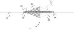
도 1 내지 도 3은, 팽창된 상태인 색전 방지 장치를 도시한 도면.
도 4 내지 도 6은, 압축된 상태(즉 전달과정동안)인 색전 방지 장치를 도시한 도면.
도 7은, 색전 방지 장치내에서 이용되는 고정 조인트를 도시한 도면.
도 8 내지 도 9는, 색전 방지 장치내에서 이용되는 필터를 도시한 도면.
도 10 내지 도 11은, 색전 방지 장치내에서 이용되는 스트럿들과 필터를 도시한 도면.
도 12 내지 도 13은, 색전 방지 장치내에서 이용되는 스트럿들을 도시한 도면.
도 14 내지 도 16은, 미끄럼 운동하는 색전 방지 장치를 도시한 도면.
도 17내지 도 18은, 색전 방지 장치와 이용되는 카테터를 도시한 도면.
도 19는, 회전가능한 색전 방지 장치를 도시한 도면.
도 20 내지 도 24는, 회전가능한 서로 다른 여러 개의 조인트들을 도시한 도면.
도 25 내지 도 26은, 팽창된 상태인 색전 방지 장치를 도시한 도면.
도 27 내지 도 28은, 도 25로부터 장치의 필터를 확대하여 도시한 도면.
도 29 내지 도 31은, 도 25의 장치를 형성하기 위한 구성의 다양한 도면.
도 32는, 포물선 필터 형상을 가진 색전 방지 장치를 도시한 도면.
도 33은, 루프 형상을 가진 복수 개의 스트럿들을 가진 필터의 단부 도면.
도 34 내지 도 35는, 외부의 "축구공(football)" 형상 스트럿을 가진 색전 방지 장치를 도시한 도면.
도 36은, 색전 방지 장치를 도시한 도면.
도 37 내지 도 40은, 다양한 신속 교체식 색전 방지 장치를 도시한 단면도.
도 41 내지 도 44는, 다양한 신속 교체식 색전 방지 장치를 도시한 측면도.
도 45 내지 도 46은, 전달 장치의 원위 단부를 개방하기 위한 카테터 절단 장치를 도시한 도면.The features, nature, and advantages of the present invention will be understood from the following description of embodiments of the invention with reference to the accompanying drawings.
Figs. 1 to 3 show an embolization device in an expanded state. Fig.
Figs. 4-6 illustrate an embolization device that is in a compressed state (i.e., during a transfer process); Fig.
7 is a view showing a fixed joint used in an embolization prevention apparatus;
Figs. 8 to 9 are diagrams showing filters used in an embolization device. Fig.
Figs. 10-11 illustrate struts and filters used in an embolization device. Fig.
Figs. 12-13 illustrate struts used in an embolization device. Fig.
Figs. 14 to 16 are diagrams showing an embolization device for sliding. Fig.
17 to 18 show a catheter used with an embolization device.
19 is a view showing a rotatable embolization device.
20 to 24 show several rotatable different joints.
25 to 26 are diagrams showing an embolization device in an expanded state.
Fig. 27 to Fig. 28 are enlarged views of the filter of the apparatus from Fig. 25; Fig.
29 to 31 are various views of the configuration for forming the apparatus of Fig.
32 is a view showing an embolization device having a parabolic filter shape;
33 is an end view of a filter having a plurality of struts with a loop shape.
34-35 illustrate an embolization device having an external " football "shaped strut.
36 is a view showing an embolization device;
Figs. 37 to 40 are cross-sectional views showing various quick-change embolization devices. Fig.
41 to 44 are side views showing various quick-change embolization devices;
45-46 illustrate a catheter cutting device for opening a distal end of a delivery device;
본 발명의 구체적인 실시예들이 첨부된 도면들을 참고하여 설명된다. 그러나 본 발명은 다수의 다른 형태로 실시될 수 있으며 본 명세서에 공개된 실시예들로 한정되지 않는다. 오히려, 이러한 실시예들은, 본 공개내용이 완전하고 통상의 기술자들에게 본 발명의 범위를 완전하게 전달하도록 제공된다. 첨부된 도면들에 도시된 실시예들에 관한 상세한 설명의 용어들은 본 발명을 한정하기 위한 것이 아니다. 도면들에서 동일한 도면부호는 동일한 구성요소들을 가리킨다.Specific embodiments of the present invention will be described with reference to the accompanying drawings. The present invention may, however, be embodied in many different forms and should not be construed as limited to the embodiments set forth herein. Rather, these embodiments are provided so that this disclosure will be thorough and complete, and will fully convey the scope of the invention to the ordinary artisan. DETAILED DESCRIPTION OF THE PREFERRED EMBODIMENTS Reference will now be made in detail to the preferred embodiments of the present invention, examples of which are illustrated in the accompanying drawings. In the drawings, like reference numerals refer to like elements.
본 명세서에서 혈전, 색전 입자들 및 유사한 용어들이 이용된다. 다르게 언급되지 않는다면, 이러한 용어들은 인체 혈관내에서 이동하거나 이동을 야기할 수 있는 불필요하고 원하지 않는 다른 위험한 입자를 가리키기 위해 일반적으로 호환하여 이용될 수 있다.Thrombosis, embolic particles, and similar terms are used herein. Unless otherwise stated, these terms are generally used interchangeably to refer to other undesirable and unwanted dangerous particles that may migrate or cause movement within the body's blood vessels.
본 명세서와 도면들은 각각 서로 다른 요소와 구조를 가진 여러 개의 실시예들을 포함한다. 상기 특정 실시예들이 설명될 때, 모든 구성요소들 및/또는 구조들은 다른 모든 실시예들과 조합될 수 있다.The specification and drawings contain several embodiments each having a different element and structure. When the foregoing specific embodiments are described, all of the elements and / or structures may be combined with all other embodiments.
혈전 제거과정 동안 제 위치에서 벗어나 혈전을 포착하기 위해 색전 방지 장치들이 이용될 수 있다. 실시예에서, 색전 방지 장치는 목표 위치로부터 원위 위치에 배열된다. 풍선 및/또는 스텐트가 이용되어 막힌 혈관을 팽창시키고 상기 색전 방지 장치는 제 위치에서 벗어나 모든 혈전들을 포착하여 혈전이 하류위치로 이동하는 것을 방지한다.An embolization device may be used to capture the thrombus from its position during the thrombus removal procedure. In an embodiment, the embolization device is arranged in a distal position from a target position. Balloons and / or stents are used to inflate the clogged blood vessels and the embolization device moves out of position to capture all thrombi to prevent the thrombus from moving to a downstream location.
도 1 내지 도 3에 도시된 색전 방지 장치의 다양한 실시예들은 각각, 색전 입자들을 포착하기 위한 확대 구조 및 도 4 내지 도 6에 도시된 전달장치(30)(즉 마이크로카테터(microcatheter))를 통해 전달될 때 색전 방지 장치가 채택하는 수축 구조를 가진다. 상기 각각의 실시예들에서, 상기 색전 방지 장치(10,11,13)들은 전달 와이어(12)위에 배열되고 혈전을 포착하기 위해 이용되는 필터(20)를 포함한다. 상기 필터(20)는 한 개이상의 와이어(예를 들어, 니티놀(Nitinol), 스테인레스강, 코발트 크롬 및/또는 폴리머 재료로 구성된 와이어)로부터 형성된 메쉬(mesh) 또는 브레이드(braid)이다. 또한, 방사선 불투과성(radiopaque) 재료(즉, 탄탈륨 또는 백금)가 메쉬를 포함한 구성 와이어에서 이용될 수 있다. 상기 메쉬 또는 브레이드 형태의 필터(20)는 단일 메쉬/브레이드 층 또는 다중 층(예를 들어, 상대적으로 큰 다공성 층 및 상대적으로 작은 다공성 층)으로부터 제조될 수 있다. 또 다른 실시예에서, 상기 필터는 단일 고형 재료(예를 들어, 레이저 커팅된 튜브(laser-cut tube))로부터 제조된다.Various embodiments of the embolization prevention device shown in Figs. 1 to 3 are respectively provided with an enlargement structure for capturing embolization particles and a transfer device 30 (i.e., a microcatheter) shown in Figs. 4 to 6 It has a contraction structure adopted by the embolization device when delivered. In each of the above embodiments, the
각각의 장치(10,11,13)는 필터(20)상의 다양한 위치들에 연결된 한 개이상의 스트럿(strut)(22)을 포함하여 과정동안 상기 필터(20)를 용이하게 팽창하고 수축시킨다. 상기 스트럿(22)들이 상기 전달 장치(30)에 대해 근위 위치 또는 가장 근접한 위치를 향하기 때문에, 각각의 장치(10,11,13)들이 상기 전달 장치(30)내에서 수축함에 따라 상기 스트럿들은 필터(20)를 폐쇄하도록 작동한다.Each
상기 스트럿(22)들과 필터(20)는 각각 고정된 조인트(14) 및 미끄럼 조인트(16)에 의해 상기 전달 와이어(12)상에서 팽창될 수 있다. 상기 스트럿(22)은, 상기 전달 와이어(12)에 대해 정지된 고정 조인트(14)에 연결된다. 상기 미끄럼 조인트(16)는 상기 필터(20)의 원위 단부에 연결되어 상기 장치가 팽창하고 수축할 때 상기 전달 와이어(12)에 대해 상기 미끄럼 조인트가 미끄럼 운동할 수 있다.The
상기 필터(20)는, 혈관의 상대적인 원위 부분으로부터 방출하는 혈전을 포착하도록 작동하기 위한 일반적인 원추형상을 형성한다. 그러므로, 상기 필터(20)의 개방(확대된) 부분은 상기 미끄럼 조인트(16)와 연결된 필터의 부분에 대해 원위 위치에 배열되고, 상기 스트럿(22)은 상기 필터(20)에 대해 원위에 배열된다.The
상기 장치(10,11,13)들은 또한 확대된 위치속으로 상기 장치를 가압하거나 편향시키는 압축 부재(18)를 포함할 수 있다. 도 1에 도시된 장치(10)를 참고할 때, 상기 압축 부재(18)는 상기 전달 와이어(12)상에 배열되고 상기 필터(20)에 대해 모두 원위 위치에 배열된 고정 조인트(15)와 스트럿(22)에 연결된다. 상기 압축 부재(18)는 금속 또는 플라스틱 스프링 형상 부재, 고형 탄성 폴리머 부재, 탄성 재료 또는 유사한 거동/기능을 가진 재료를 포함할 수 있다.The
도 4는, 전달 장치(30) (즉, 마이크로카테터)내에 배열될 때 상기 색전 방지 장치(10)의 압축된 구조를 도시한다. 상기 필터(20)가 상기 전달 장치(30) 내에 배열되는 동안 접혀지면서, 상기 필터(20)와 스트럿(22)은 상기 미끄럼 조인트(16)에 대해 하중을 발생시킨다. 미끄럼 조인트(16)는 고정 조인트(15)를 향해 원위 방향으로 이동하여 상기 압축 부재(18)를 압축시킨다. 상기 색전 방지 장치(10)가 상기 전달 장치(30)로부터 구속해제될 때, 상기 압축 부재(18)는 압축된 구조로부터 팽창된 구조로 이동하고 상기 필터(20)와 스트럿(22)을 개방 또는 팽창된 구조로 근위 방향으로 가압한다. 상기 필터(20) 및/또는 스트럿(22)가 팽창된 구조로 편향(biased)되거나 "열 소성(heat- set)"되는 형상 기억 재료로 제조되기 때문에, 상기 부품들은 상기 전달 장치(30)로부터 전개된 후에 추가로 팽창하중을 발생시킬 수 있다. 또한, 상기 고정 조인트(15)는 상기 압축 부재(18)를 고정하고 다음에 상기 필터(20)의 과도한 팽창(over expansion)에 대해 후방정지부(backstop)를 형성하게 된다.Fig. 4 shows the compressed structure of the
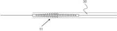
도 2의 장치(11)를 참고할 때, 압축 부재(18)는 미끄럼 조인트(16)와 고정 조인트(15)사이의 영역에 걸쳐 형성된다. 도 5는, 도 2의 색전 방지 장치(101)가 전달 장치(30) (즉, 마이크로카테터)내에 배열될 때 압축된 구조를 도시한다. 상기 필터(20)가 상기 전달 장치(30) 내에 배열되는 동안 접혀지면서, 상기 필터(20)와 압축 부재(18)는 상기 미끄럼 조인트(16)에 대해 하중을 발생시키고, 미끄럼 조인트(16)는 원위 방향으로 이동하여 상기 압축 부재를 펼쳐지게 한다. 상기 색전 방지 장치(11)가 상기 전달 장치(30)로부터 제거될 때, 상기 압축 부재(18)는 조인트(14,16)들사이에서 구속되지 않은 인장(pulling) 하중을 발생시키고 상기 필터(20)를 팽창시키며 팽창된 형상을 유지한다. 상기 필터(20) 및/또는 스트럿(22)가 팽창된 구조로 편향되거나 "열 소성"되는 형상 기억 재료로 제조되기 때문에, 상기 부품들은 상기 전달 장치(30)로부터 전개된 후에 추가로 팽창하중을 발생시킬 수 있다.Referring to the
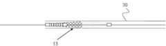
도 3에 도시된 색전 방지 장치(13)를 참고할 때, 상기 압축 부재(18)는 미끄럼 조인트(16)와 원위 고정 조인트(15)사이에 연결된다(원위 고정 조인트(15)는 고정 조인트(14)에 대해 원위 위치에 배열된다). 도 1에 도시된 색전 방지 장치(10)의 실시예와 대조적으로, 상기 압축 부재(18)는 상기 필터(20)내에 위치한다. 도 2에 도시된 색전 방지 장치(11)의 실시예와 대조적으로, 상기 압축 부재(18)는 상기 미끄럼 조인트(16)와 고정 조인트(14)사이에서 단지 부분적으로 팽창한다.3, the
도 6은, 도 3에 도시된 색전 방지 장치(13)의 압축된 구조를 도시한다. 상기 색전 방지 장치(13)가 상기 전달 장치(30)를 빠져나감에 따라, 상기 압축 부재(18)는 수축하고 상기 미끄럼 조인트(16)를 상기 고정 조인트(15)를 향해 근위 방향으로 끌어당긴다. 상기 필터(20) 및/또는 스트럿(22)가 팽창된 구조로 편향되거나 "열 소성"되는 형상 기억 재료로 제조되기 때문에, 상기 부품들은 상기 전달 장치(30)로부터 전개된 후에 추가로 팽창하중을 발생시킬 수 있다.Fig. 6 shows the compressed structure of the
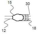
도 7은, 도 1에 도시된 원위 고정 조인트(15)의 구조에 관한 실시예를 도시한다. 상기 실시예에서, 원위 고정 조인트(15)는 전달 와이어(12)와 압축 부재(18)사이에서 테이퍼 형상을 가진다. 선호적으로, 상기 고정 조인트(15)는 매끄러운 프로파일을 가지고 날카로운 변부를 가지지 않아서, 상기 색전 방지 장치(10)는 맥관구조(vasculature)를 통해 추적됨에 따라 혈관 외상(trauma)을 감소시킨다. 상기 장치의 프로파일이 전달 장치(30)의 원위 단부와 작동하며 짝을 이루도록 장치의 프로파일이 형성된다. 도 7에서, 상기 원위 고정 조인트(15)는 전달 장치(30)에 대해 단지 원위 위치에 배열되고 상기 전달 장치(30)의 원위 개구부와 짝을 이룬다.Fig. 7 shows an embodiment relating to the structure of the distal fixed joint 15 shown in Fig. In this embodiment, the distal fixed joint 15 has a tapered shape between the
도 7에 도시된 원위 고정 조인트에 대해 설명된 형상은 도 2 및 도 3에 도시된 색전 방지 장치(11,13)의 미끄럼 조인트(16)상에서 이용될 수 있다. 이렇게 하여, 가장 원위 위치(distal most)의 조인트가 상기 전달 장치(30)내에 배열될 때, 상기 조인트는 상기 장치의 나머지부분을 위한 "밀봉부(seal)"로서 효과적으로 작동할 것이다.The shape described for the distal fixed joint shown in Fig. 7 can be used on the sliding
도 8에 도시된 실시예에서, 상기 장치(15)는 외측부를 안쪽으로 반전시키는 필터(21)를 포함하여 벌어진 외부 층 및 감소된 내부 층을 형성한다. 상기 필터(21)는 단일층으로부터 내부로 끌어 당겨져 제2 하부 층(underlying layer)을 형성한다. 실시예에서, 상대적으로 작은 직경의 튜브가 필터(20)를 형성하는 메쉬 또는 브레이드내에서 내측에 배열된다. 다음에 상기 메쉬 또는 브레이드의 일부분이 상기 상대적으로 작은 직경의 튜브를 통해 끌어 당겨져서 필터의 상대적으로 작은 직경 영역을 형성한다. 상기 필터(20)는 상기 최종 형상으로 열성형(heat set)되고, 상기 필터의 자유 단부들은 공통 요소(즉 미끄럼 조인트(16))속으로 삽입되거나 양쪽 기술들이 이용될 수 있다. 선택적으로, 상기 필터(21)는 상기 메쉬 또는 브레이드의 외경상에 상대적으로 큰 직경의 튜브를 배열하고 다음에 메쉬 또는 브레이드를 상기 튜브상에서 느슨하게 끌어당겨서 상대적으로 크게 벌어진 영역을 형성한다.In the embodiment shown in Fig. 8, the
도 9에 도시된 또 다른 실시예에서, 상기 장치(17)의 필터(23)는 내측부를 외부로 반전시키고 내부층과 외부층을 형성한다. 상기 필터(23)는 자신에 대해 외부를 향해 끌어 당겨지고 접혀져서 외부의 제2 층을 형성한다. 상기 외부층은 팽팽하게 당겨져서 도 9에 도시되고 상대적으로 긴 프로파일을 형성하거나 느슨한 상태로 남겨져서 도 8에 도시된 프로파일과 유사한 프로파일을 형성할 수 있다. 실시예에서, 상대적으로 큰 직경의 튜브는, 필터를 형성하는 메쉬 또는 브레이드에 대해 외부에 배열된다. 상기 메쉬 또는 브레이드의 일부분이 상기 튜브의 외경위에서 외경 주위로 이동하여 제2 중첩 영역을 형성한다. 상기 필터는 상기 최종 형상으로 열성형(heat set)되고, 상기 필터의 자유 단부들은 공통 요소(즉 미끄럼 조인트(16))속으로 삽입되거나 양자 기술들이 이용될 수 있다. 선택적으로, 상기 필터(23)는 상기 메쉬 또는 브레이드 아래에서 상대적으로 작은 직경의 튜브를 배열하고 다음에 메쉬 또는 브레이드를 상기 튜브 아래에서 팽팽하게 끌어당겨서 하부 영역을 형성한다.In another embodiment shown in Fig. 9, the
상기 설명과 같이, 본 명세서에 설명된 여러 개의 실시예들은, 상기 필터(20)와 연결되고 지지하는 다수의 스트럿(22)들을 포함한다. 상기 스트럿(22)은, 제어된 구속 하중(restraining force)을 제공하여 필터(20)의 팽창을 제어할 수 있다. 일부 실시예들에서 상기 스트럿(22)들이 고정 조인트(14)와 연결되기 때문에, 상기 필터(20)를 상기 전달 장치(30) 속으로 다시 삽입할 때 스트럿들은 상기 필터(20)가 접혀지는(collapse) 것을 용이하게 한다. 다시 삽입되는 동안, 상기 스트럿(22)들은 상기 필터(20)위에 상기 미끄럼 조인트(16)와 압축 부재(18)의 작용과 함께 구속하중을 제공한다. 따라서, 상기 스트럿(22)들은 상기 필터(20)의 팽창을 제어하고 상기 전달 장치(30) 속으로 삽입되는 동안 상기 필터(20)가 접혀지는 것을 용이하게 한다.As described above, the various embodiments described herein include a plurality of
상기 스트럿(22)들이 다수의 형태로 구성될 수 있다. 한 가지 예에서, 금속재질의 스트럿(22)이 도 9에 도시된 이중 층 필터(23)와 이용될 수 있다. 한 가지 예에서, 상기 스트럿(22)들은 반전되거나 뒤집힌(everted) 메쉬의 양쪽 층들과 연결되어 연결을 위한 상대적으로 강한 고정점(anchor point)을 제공한다. 상기 스트럿(22)들은, 상기 필터(23)에 연결되기 위한 연결 부재(24)(예를 들어, 후크 형상 또는 루프(loop))를 포함할 수 있다. 상기 연결 부재(24)는 상기 필터(23)와 연결되는 형상을 가지도록 열성형되거나 상기 필터(23)에 접합되도록 직접 처리될 수 있다. 실시예에서, 연결 부재(24)는 상기 스트럿(22)의 단부를 포함하는 코일이며 상기 필터(23)의 구멍을 통과하는 루프(loop)를 형성한다. 상기 코일에 의해 상기 스트럿(22)은 상기 필터(23)에 대해 고정되고 상대적으로 부드럽고 더 높은 표면 영역인 표면을 제공하여 상기 필터를 가압한다. 니티놀, 스테인레스강, 폴리머, 방사선 불투과성 재료(즉, 탄탈륨 또는 백금) 및 이들의 조합을 포함한 다수의 재료들이 상기 스트럿(22)을 위해 이용될 수 있다.The
도 11에 도시된 또 다른 실시예에 있어서, 상기 스트럿(22)은 각각 상기 필터(23)상의 구멍(pores)을 통해 연장되고 다시 자신으로 연결되어 단부 루프(end loop)를 형성하는 단일 와이어이다. 상기 와이어의 단부는, 주름구조를 가진 슬리브와 같은 연결요소를 통해 자신으로 고정되거나 접착제, 용접 유사한 기술에 의해 서로 결합될 수 있다.11, the
도 12에 도시된 또 다른 실시예에서, 한 개이상의 스트럿(22)들이 상기 필터(20)의 해당 곡선 영역과 결합되는 곡선 영역(26)을 가진다. 상기 곡선 영역(26)은 단일 스트럿(22)으로부터 연장되거나 두 개의 스트럿(22)들사이에서 연장되고 추가로 용접되거나 열처리되어 상기 필터(20)의 해당 곡선 영역에 고정될 수 있다. 상기 설계에 의해 상기 전달 장치(30)속으로 수축되어 형성되는 하중이 상기 필터(20)의 상대적으로 큰 영역에 걸쳐 확산될 수 있다.In another embodiment shown in FIG. 12, one or
도 13의 또 다른 실시예에 의하면, 상기 스트럿(22)들은 한쪽 단부에서 관형 단부를 가지고 다른 한쪽 단부에서 복수 개의 핑거(finger)들을 가진 튜브(예를 들어, 레이저 커팅된 니티놀 튜브)로부터 제조된다. 상기 핑거들은 스트럿(22)으로서 작동하고 상기 필터(20)의 변부들에 연결된다. 상기 실시예에서, 상기 핑거들과 마주보는 관형 영역은 주름구조를 가지거나 상기 전달 와이어(12)에 고정되어, 고정된 조인트로서 작동할 수 있다.According to another embodiment of Figure 13, the
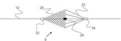
도 14에 도시된 색전 방지 장치(9)의 또 다른 실시예는, 장치(9)의 근위 단부에서 미끄럼 조인트(sliding joint)(34)를 가지고 장치(9)의 원위 단부에서 제2 미끄럼 조인트(32)를 포함한다. 두 개의 정지부(32,34)들사이에 위치한 정지부(28)는 장치(9)의 원위 및 근위 병진 운동을 제한한다. 다시 말해, 장치의 원위 병진 운동은 (도 15에 도시된) 근위 슬라이더(proximal slider)(34)와 상호작용하는 정지부(28)에 의해 제한되고, 장치의 근위 병진 운동은 (도 16에 도시된) 원위 슬라이더(distal slider)(32)와 상호작용하는 정지부(28)에 의해 제한된다. 상기 미끄럼 조인트(32,34)들은 전달 와이어(12) 주위에 확산되거나 포착되지만, 와이어와 최소 마찰을 발생시켜서 조인트(32,34)들이 용이하게 미끄럼 운동하게 만든다.Another embodiment of the
도 17 내지 도 18은, 색전 방지 장치(10)( 또는 본 명세서에 설명된 모든 장치들)의 전달을 위해 이용되는 신속 교체 카테터(rapid exchange catheter)(31)의 실시예를 도시한다. 상기 카테터(31)는 안내 와이어(guide wire)(40)를 위한 접근 포트로서 이용되는 원위 포트(36)를 포함하고, 상기 안내 와이어는 삽입될 때 카테터(31)를 맥관구조내에서 특정 목표 영역으로 직접 전달하거나 추적하기 위해 이용된다. 근위 포트(38)는 색전 방지 장치(10)를 위한 접근 포트로서 이용되고 상기 색전 방지 장치가 상기 안내 와이어(40)에 의해 제공되는 원하는 목표 위치에 도달할 수 있게 한다.17-18 illustrate an embodiment of a
실시예에서 상기 안내 와이어(40)와 전달 와이어(12)의 직경은 모두 약 0.014"일 수 있다. 더 크거나 작은 다양한 직경이 이용될 수 있고 이러한 수치는 단지 예로서 제공될 뿐이다.In an embodiment, the diameter of the
도 20 내지 도 24에 도시된 것처럼 본 발명의 또 다른 특징에 의해 한 개이상의 근위 조인트(44) 및/또는 원위 조인트(42)는 회전할 수 있다. 상기 원위 조인트(42)는 회전하여 필터가 확대되거나 수축됨에 따라 맥관구조내에서 상기 필터(20)의 회전운동을 허용하는 것이 선호된다. 따라서 상기 장치(10)는 환자의 혈관에 더욱 양호하게 일치하고 장치(10)의 불필요한 작용을 유발시키는 불필요한 응력을 감소시킨다.20-24, one or more
도 20에 도시된 회전가능한 조인트(42A)의 실시예는, 전달 와이어(12)에 대한 병진운동 및 회전운동으로부터 고정되는 두 개의 확대 섹션(enlarged section)(46A)들을 가진다. 외부 회전 부재(42A)는 상기 와이어(12)에 직접 끼워맞춤되어 상기 와이어(12)를 포착하는 반면에, 상기 확대 섹션(46A)은 상기 영역(42A)의 병진운동을 방지한다. 따라서, 상기 외부 회전 부재(42A)(및 외부 회전 부재에 부착되는 모든 것)은 제 위치에서 회전할 수 있다.The embodiment of the rotatable joint 42A shown in Fig. 20 has two
도 21에 도시된 조인트(42B)의 또 다른 실시예에서, 외부 회전 부재(43)는 고정된 확대 부재(46B)를 수용하는 요홈구조의 공동(recessed cavity)을 포함한다. 앞서 설명한 조인트(42A)에서와 같이, 고정된 확대 부재(46B)는 상기 와이어(12)에 고정되어 병진 운동 및 회전운동을 방지한다. 상기 부재(46B)는 또한 부재가 상기 외부 회전 부재(43)의 감소직경 부분을 통과할 수 없는 충분한 크기를 가진다. 따라서, 상기 외부 회전 부재(43)는 효과적으로 상기 부재(46B)를 포착하지만 제 위치에서 회전할 수 있다.In another embodiment of the joint 42B shown in FIG. 21, the outer rotating
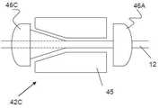
도 22에 도시된 조인트(42C)의 또 다른 실시예는 일반적으로 조인트(42A)와 유사하지만 고정된 확대 부재(46B)들 중 한 개는 테이퍼 영역을 포함하며, 외부 회전 부재(45)는 상호 테이퍼 구조를 포함한다. 유사하게, 도 23에 도시된 조인트(42E)의 또 다른 실시예에서, 외부 회전 부재(47)의 양쪽 단부들은 고정된 두 개의 확대 부재(46C)들과 왕복 운동하는 테이퍼 영역들을 가진다. 마지막으로, 도 24에 도시된 조인트(42E)의 또 다른 실시예는 일반적으로 조인트(42B)와 유사하지만 외부 회전 부재(49)는 상호 테이퍼 구조를 가지고 고정된 확대 부재(46E)를 포착하는 테이퍼 구조의 요홈 영역(tapered recessed area)을 포함한다.Another embodiment of the joint 42C shown in FIG. 22 is generally similar to the joint 42A, but one of the fixed
상기 조인트들은, 니티놀, 스테인레스강, 코발트 크롬, 폴리머, 방사선 불투과성 재료(즉, 탄탈륨 또는 백금) 및 이들의 조합을 포함한 다수의 재료들을 포함한 재료로 구성될 수 있다. 앞서 설명한 것처럼, 상기 회전 조인트들은 본 명세서에서 설명된 모든 실시예들에서 이용될 수 있다. 또한, 확대 부재(46A 내지 46E)들은 오프셋(offset) 배열(또는 공동 하우징에 대해 수축)되어 회전운동뿐만 아니라 약간의 병진운동 자유도(translational freedom)를 허용한다.The joints may be composed of a material comprising a plurality of materials including nitinol, stainless steel, cobalt chrome, a polymer, a radiopaque material (i.e., tantalum or platinum), and combinations thereof. As described above, the rotational joints can be used in all of the embodiments described herein. In addition, the expanding
도 25에 도시된 색전 방지 장치(50)의 또 다른 실시예는, 장치(50)가 근위 고정 조인트(proximal fixed joint)(58) 및 원위 미끄럼 조인트(60)를 가지고 팽창할 수 있는 원추형 필터(64)를 포함한다는 점에서, 일반적으로 앞서 설명한 실시예들과 유사하다. 앞서 설명한 실시예들과 다르게, 상기 필터(64)는 튜브(56)(예를 들어, 폴리이미드 튜브)상에 분포되고 상기 튜브상에 조인트(58,60)들이 배열되며 전달 와이어(12)와 안내 와이어(40)의 통과를 허용한다. 이와 관련하여, 장치(50)는 "모노레일(monrail)" 또는 신속 교체형 필터로서 작용한다. 실시예에서 전달와이어(12)는 튜브(56)의 전부 또는 일부분속에(튜브(56)가 상기 전달 와이어위에 배열되는 위치에) 배열되며, 다른 실시예에서 전달 와이어(12)의 구성은 튜브(56)의 근위 단부에서 끝난다.Another embodiment of the
도 25 내지 도 27에서 가장 양호하게 도시된 것처럼, 상기 필터(64)는 상대적으로 큰 직경을 가진 복수 개의 와이어(54)들로 직조되고 상대적으로 작은 직경을 가진 복수 개의 와이어(52)들로 구성되는 것이 선호된다. 예를 들어, 상대적으로 작은 와이어(52)들은 약 0.0005 내지 0.00225인치 범위의 직경을 가질 수 있으며, 상대적으로 큰 직경의 와이어(54)들은 약 0.00225 내지 0.008인치 범위의 직경을 가질 수 있다. 또한, 상대적으로 큰 직경을 가진 약 4개 내지 16개의 와이어(54)들이 이용될 수 있고 상대적으로 작은 직경을 가진 약 72개 내지 288개의 와이어(52)들이 이용될 수 있다.As best shown in Figures 25-27, the
아래에서 더욱 상세하게 설명하는 것처럼, 상대적으로 큰 직경을 가진 와이어(54)는 또한 장치(50)의 근위 단부에서 스트럿을 형성할 수도 있다. 선택적인 실시예에서, 큰 직경을 가진 와이어(54)는 와이어(52)와 동일하거나 더 작은 지경을 가질 수 있지만, 상대적으로 강하거나(stronger) 단단한(stiffer) 재료(예를 들어, 코발트 크롬(cobalt chromium) 와이어(54) 및 니티놀 와이어(52))로 구성될 수 있다.As will be described in greater detail below, a
도 25 및 도 26에 가장 잘 도시된 것처럼, 필터(64)가 확대된 구조를 가질 때 필터는 일반적으로 원추형상을 가지며 상대적으로 적은 구멍을 가진 단부부분(64A)(즉 개방 단부와 근접한 영역)을 가진다. 상기 장치(50)가 과정동안 입자들을 포착하고 사용자가 상기 필터(64)를 수축시킨 후에, 상기 단부 부분(64A)의 직경은 확대되고 감소되며 상대적으로 큰 근위 와이어(54)의 일반적인 형상을 따른다. 상기 단부 부분(64A)의 적어도 부분적인 팽창상태가 도 26에 도시된다. 이와 관련하여, 상기 필터(64)는, 상기 필터(64)의 나머지 원위 부분들의 직경이 상당히 감소되기 전에, 상기 필터(64)내에 포착된 모든 입자들의 근위 부분 주위를 밀폐하거나 단단히 매여(cinch)있다. 다시 말해, 상기 필터(64)의 근위 단부는 우선 적어도 부분적으로 밀폐되고 상기 필터(64)의 원위 단부가 상기 입자들을 압착하여 환자의 혈관속으로 이동시키는 것을 방지한다. 상기 단부 부분(64A)은 상기 나머지 부분이 아니라 상기 영역을 더욱 압축된 구조로 열성형하여 형성되거나 다양하거나 서로 다른 직조 패턴(weave pattern)으로부터 형성될 수 있다. 선택적으로, 단부 부분(64A)은 도면의 감소되는 프로파일 대신에 사실상 일정한 직경의 프로파일을 가질 수 있다.25 and 26, when the
도 28 내지 도 31에 도시된 다양한 예시적 단계들은 상기 장치(50)를 형성하기 위해 이용될 수 있다. 도 29를 참고할 때, 관형의 스텐트(stent)와 같은 구조체(63)가 우선 앞서 설명한 와이어(52,54)들에 의해 직조되거나 브레이드(braided)될 수 있다. (최종가공된 필터(64)내에서 단부 부분(64)으로서 설명되는)중심 영역(64A)이 상기 튜브(63)의 나머지 부분보다 압축된 구조에 열성형(heat set)되는 것이 선호된다.The various exemplary steps shown in Figs. 28-31 may be used to form the
도 30을 참고할 때, 상기 튜브(63)의 근위 단부는 고정된 조인트 부재(58)에 의해 상기 튜브(56)상에서 주름구조를 가지며, 상기 튜브(63)의 근위 단부는 상기 튜브(56)의 미끄럼 조인트(60)에 연결된다. 상기 배열은 두 개의 원추형 단부(64B)들을 가진 메쉬 구조체를 형성한다.30, the proximal end of the
도 31을 참고할 때, 다음에 단지 상대적으로 작은 직경의 와이어(52)들이 트리밍(trimmed) 가공되어 단지 상대적으로 큰 직경의 와이어(54)가 장치(50)의 근위 단부에 유지된다. 실시예에서, 와이어(52)들은 상기 단부 부분(64A)의 단지 근위위치에서 고정 조인트(58)에 대해 트리밍된다. 도 28에 도시된 것처럼, 상기 필터(64)의 개구부 주위에서 와이어(52)의 자유 단부들은 전해 연마(electropolish)되어 외상 또는 마모 경향을 감소시킨다. 마지막으로, 가요성을 가진 제2 원위 튜브(62)가 튜브(56)의 단부에 고정되어 상기 장치(50)는 비외상성 팁(atraumatic tip)을 가진다. 가요성 튜브(62)는 폴리머(즉 PTFE) 또는 금속으로 제조될 수 있고 일정하거나 가변적인 강성의 프로파일을 가질 수 있다. 가변적인 강성(stiffness) 프로파일은 튜브의 길이를 따라 등급을 매긴 강성을 가지도록 이용될 수 있고, (혈관과 접촉하게 되는) 가장 원위 부분은 더 큰 가요성을 가질 것이다. 상기 가변적인 강성 프로파일은, 서로 다른 재료 프로파일을 가진 튜브의 길이를 따라 다양한 폴리머 또는 금속을 이용하여 달성될 수 있다. 실시예에서, 레이저 커팅된 나선형 패턴이 금속 또는 폴리머 튜브에 이용된다. 상기 튜브 아래에 코일이 위치하고 폴리머가 상기 코일에 열성형(즉 열 수축된 튜브구조)된다. 상기 코일은 가요성 튜브 섹션에 대해 추가로 가요성을 제공할 수 있다. 가요성 튜브(62)는, 맥관구조를 통한 추적(tracking)을 가능하도록 안내와이어가 배열된 채널을 포함한다.31, only relatively
선택적으로 도 27에 도시된 것처럼, 한 개이상의 방사성 불투과 마커(marker)(53)들이 필터(64)상의 여러 위치들에 고정될 수 있다. 예를 들어, 마커(53)들은, 단부 부분(64A)과 근접한 위치 또는 필터(64)의 자유 단부(즉, 상기 와이어(52)의 전해 연마된 자유 단부들과 근접한 위치)에서 상대적으로 큰 와이어(54)에 고정될 수 있다.Optionally, as shown in FIG. 27, one or more radio
도 32에 도시된 색전 방지 장치(70)의 또 다른 실시예는 일반적으로 앞서 설명한 실시예들과 유사하지만, 일반적으로 포물선 형상을 가진 색전 방지 장치의 필터(72)를 추가로 포함한다. 더욱 직선이거나 선형으로 감소하는 대신에 상기 필터(72)에 대해 더욱 곡선인 원위 단부(72A)를 제공하여, 필터 메쉬의 구멍 크기(pore size)는 더욱 일정하게 유지되고 따라서 필터를 통과하는 원위 혈액 유동을 개선시킬 수 있다.Another embodiment of the
도 33은 필터(76)의 원위 단부도면으로서, 상기 필터는 상기 필터(76)의 메쉬를 위한 지지 바스켓(78)을 형성하는 더 큰 직경의 와이어들을 가지거나 복수 개의 스트럿들을 가진다. 일반적으로, 상기 바스켓(78)은 추가의 지지 기능을 제공하고 심지어 필터(76)의 팽창/수축을 용이하게 한다. 실시예에서, 상기 바스켓(78)의 와이어는 니티놀로 제조되고 "개방"되거나 팽창된 상태의 원하는 구조로 열성형 된다. 상기 바스켓(78)은 상기 필터(76)내에 배열되고 필터 메쉬내에 직조되거나 상기 필터(76)의 외측부에 배열되고 고정될 수 있다.33 is a distal end view of a
도 34 및 도 35에 도시된 색전 방지 장치(80)의 또 다른 실시예는, 필터(84)에 고정되고 기다란 복수 개의 스트럿(82)들을 가진다. 상기 스트럿(82)들은, 도 34에 도시된 축구공/타원 형상 또는 도 35에 도시되고 부분적으로 반전된 형상의 구조로 열성형 되고 이러한 형상들로 압축되고 전개될 수 있다. 선택적으로 스트럿(82)들은 열 성형되어 팽창되고 부분적으로 반전된 도 35의 형상을 가지지만 도 34의 형상일 때 전달장치(30)속으로 투입(loaded)될 수 있어서 전개된 후에 도 35의 형상으로 자체 반전(self inverting)된다. 상기 실시예들에서, 스트럿들은 니티놀 튜브를 레이저 커팅하여 형성되고 "단일 몸체(unibody)" 프레임 구조체를 형성하며 혈관벽을 따라 하중을 균일하게 분포시킨다.Another embodiment of the
도 36에 도시된 색전 방지 장치(86)의 또 다른 실시예는 일반적으로 타원형상 또는 계란형상을 가진다. 상기 장치(86)는 상대적으로 큰 직경의 와이어(88) 및 상대적으로 작은 직경의 와이어(87)를 가지며 스텐트와 같은 관형 구조체에 의해 형성될 수 있다. 본 명세서에 설명된 다른 실시예들에서와 같이, 근위 단부는 전달 와이어(12)에 대해 주름 구조를 가지거나 고정 조인트에 의해 연결되며, 원위 단부는 미끄럼 조인트에 의해 전달 와이어(12)에 연결될 수 있다.Another embodiment of the
예를 들어, 도 25의 장치(50)에 관해 앞서 설명한 것처럼, 고정 조인트(58)와 같이 본 명세서에 설명되는 장치들의 가장 근위 부분은 안내 와이어(40)뿐만 아니라 (상기 장치가 배열되는) 전달 와이어(12)를 수용하여, 모노 레일 또는 신속 교체형 카테터로서 작용한다. 도 37 내지 도 44에 도시된 예들과 같은 상기 와이어(12,40)들을 수용하기 위해 서로 다른 여러 개의 구조들이 가능하다는 것을 이해해야 한다.25, the proximal portion of the devices described herein, such as the fixed joint 58, may include not only the
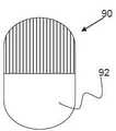
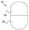
도 37 내지 도 38은 도 17 내지 도 18의 변형을 포함하여 신속 교체형 카테터 포트들의 다른 구조들을 도시한다. 상기 포트는 두 개의 부분들로 분할된 커다른 한 개의 개구부를 포함한다. 더욱 원위적으로 배열된 포트(즉,96)는, 더욱 근위적으로 배열된 포트(즉, 98)가 색전 방지 장치를 위해 이용되는 동안 안내 와이어를 위해 이용될 수 있다. 도 37에 도시된 것처럼, 상기 포트들 중 한 개(즉 더욱 원위적인 포트(90))는 천공구멍을 가져서 목적에 맞는 포트가 어느 것인지를 촉감으로 알 수 있게 한다.Figs. 37-38 illustrate other constructions of fast replaceable catheter ports, including variations of Figs. 17-18. The port includes one larger opening divided into two portions. Ports (i.e., 96) that are more strategically arranged may be used for the guide wire while more proximal ports (i.e., 98) are utilized for the embolization device. As shown in Figure 37, one of the ports (i.e., the more distal port 90) has a perforation hole so that it can be tactile to know which port is suitable for the purpose.
도 39 내지 도 40은, 신속 교체 능력을 가진 장치 실시예들의 고정 조인트 또는 가장 근위 부분이 가지는 예시적인 단면 구조를 다양하게 도시한다. 도 39에서, 단면(100)은 제1 통로(102) 및 제2 통로(104)를 포함하고, 상기 통로들 중 한 개는 안내와이어(40)를 수용하고 다른 한 개의 통로는 전달 와이어(12)를 수용한다. 도 40에 도시된 단면(106)은, 안내 와이어(40)를 위한 제1 곡선 통로(108) 및 전달 와이어(12)를 위한 제2 원호형상 통로(110)를 가진다. 상기 예에서, 상기 전달 와이어(12)는 일반적으로 또한 상기 통로 내에 끼워 맞춤되도록 원호 형상을 가질 수 있다. 상기 통로(110)는 또한 통로(108)와 상대적으로 근접하게 배열되는 것이 선호되고 통로(108)의 직경보다 약간 큰 내부 원호 형상을 가지며 장치의 전체 직경을 감소시킨다.Figs. 39-40 illustrate various exemplary cross-sectional configurations of the fixed joint or proximal portion of the device embodiments with rapid replacement capability. 39,
도 41 내지 도 44를 참고할 때, 실시예들은 다양한 예시적인 포트 및 통로 위치들을 공개한다. 도 41을 참고할 때, 동일한 내부 통로(120A)까지 형성된 제1 포트(120C) 및 제2 포트(120B)를 가진 고정 조인트(120)가 도시된다. 그러므로, 안내 와이어가 중심으로부터 약간 왜곡되어 포트(40)를 통과하는 동안 전달 와이어(12)는 직접 포트(120C)를 통과할 수 있고 장치를 통과하는 동일한 통로(120A)를 공유한다.With reference to Figures 41-44, embodiments disclose various exemplary port and path locations. 41, there is shown a fixed joint 120 having a
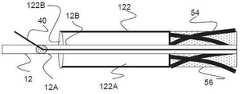
도 42에서, 고정 조인트(122)는 단지 장치를 통과하는 단일 포트(122B) 및 단일 통로(122A)를 포함한다. 그러므로, 전달 와이어(12)와 안내 와이어(40)는 포트(122B)와 통로(122A)를 공유할 수 있다.In Figure 42, the fixed joint 122 includes only a
도 43을 참고할 때, 조인트(124)는 포트(124B)로 개방되는 제1 통로(124A) 및 포트(124D)로 개방되는 제2 통로(124C)를 포함한다. 이와 관련하여, 상기 안내 와이어(40)는 자신의 통로(124A) 및 포트(124B)를 통해 이동하며, 전달 와이어(12)는 통로(124C) 및 통로(124)내에서 작동할 수 있다.43, the joint 124 includes a
마지막으로, 도 44는 도 42에서와 유사하게, 단일 통로(122A) 및 포트(122B0를 가진 조인트(122)를 도시한다. 그러나, 전달 와이어(12)는 포트(12B) 및 장치의 원위 단부에서 근위적으로 개방되는 자신의 내부 안내와이어 통로(12b)를 추가로 포함한다. 상기 포트(12A)는 정상적인 작동시 조인트(122)의 근위적으로 배열되도록 포트(12A)가 배열되는 것이 선호된다. 이와 관련하여, 안내 와이어(40)는, (예를 들어, 비외상성 단부를 통해) 장치속으로 통과하고 와이어(12)의 원위 단부속으로 통과하며 통로(12B)속을 통과하고 마지막으로 포트(12A)를 빠져나온다. 상기 통로(12B)와 포트(12A)는 안내 와이어(40)를 수용하는 크기를 가지는 것이 선호된다. 선택적으로 조인트 자체는 도 43의 포트(124B)와 같은 포트를 포함할 수 있고, 상기 포트는 상기 안내 와이어가 삽입될 수 있는 전달 와이어내에서 포트속으로 형성된다.44 shows a joint 122 with a
근위 조인트(58) 및 원위 조인트(60)는 앞서 설명하고 병진운동할 수 있는 원위 및 고정식 근위 예들을 제외하면 서로 다른 구조들을 포함할 수 있다. 예를 들어, 근위 조인트(58)는 (상기 근위 조인트와 근접하게 배열된 한 개이상의 정지부들을 통해) 약간의 병진운동 능력 및/또는 튜브(56)에 완전히 고정되지 않은 조인트를 통해 약간의 회전운동 능력을 가질 수 있다. 조인트와 근접하게 배열된 한 개이상의 정지부들을 포함하여 더욱 제한된 병진운동 능력 및/또는 상기 튜브(56)에 완전히 고정되지 않은 조인트를 통해 약간의 회전능력을 가질 수 있다.The proximal joint 58 and the distal joint 60 may include different structures except for the distal and fixed proximal examples described above and capable of translational motion. For example, the proximal joint 58 may have slight translational motion (via one or more stops arranged in close proximity to the proximal joint) and / or slight rotation through a joint that is not fully secured to the
마이크로카테터와 같은 전달장치의 또 다른 특징에 의해 전달장치의 원위 단부가 개방되거나 확대되어 약간의 테이퍼 구조를 가진 원위 단부가 형성되고 본 명세서의 다양한 색전 방지 장치들이 부드럽게 전개되고 수축된다. 도 45와 도 46에 도시된 실시예에서, 색전 방지 장치가 전개되기 바로 전에 절개부(cut) 또는 슬릿(slit)(136)이 전달 장치(130)내에 형성될 수 있다. 전달 장치(130)의 벽을 절단하거나 제거하도록 형성된 개방 장치(134)는, 전달 장치(130)의 원위 단부에 위치하거나 원위 단부와 근접하게 위치할 수 있다. 와이어(132)는 갭강 장치(134)에 연결되고 상기 전달 장치(130)의 근위 단부까지 연장되어 외과의사는 상기 개방 장치(134)를 끌어당기게 하여 절개부(cut)를 형성할 수 있다. 실시예에서 상기 와이어(132)는 전달 장치(130)내부의 자신의 통로내에 배열된다. 또 다른 실시예에서, 천공구멍이 전달 장치(130)의 벽을 따라 위치하여 상기 절개부의 형성을 용이하게 한다. 또 다른 실시예에서, 상기 전달 장치(130)의 원위 단부는, 절개부(136)가 형성된 다음에 외측으로 확대되도록 편향되는 "C"자 형상 금속부품을 포함한다.Another feature of the delivery device, such as a microcatheter, opens or enlarges the distal end of the delivery device to form a distal end with a slight tapered configuration and the various embolization devices herein smoothly expand and contract. 45 and 46, a cut or slit 136 may be formed in the
본 발명이 특정 실시예들과 적용예들에 관하여 설명되지만, 통상의 지식을 가진 자는 상기 설명을 고려하여 본 발명의 범위내에서 본 발명의 사상에 따라 추가의 수정예들과 실시예들을 형성할 수 있다. 따라서, 본 명세서의 도면과 설명은 단지 예로서 제공되어 본 발명의 이해를 돕고 본 발명을 제한하는 것으로 이해되어서는 안된다.While the present invention has been described with respect to specific embodiments and applications, it is to be understood by those skilled in the art that the foregoing description, taken in conjunction with the accompanying drawings, illustrate embodiments of the invention and, . Accordingly, the drawings and description thereof are provided by way of example only and are not to be construed as a comprehension of the present invention and as a limitation of the present invention.
Claims (31)
Translated fromKorean기다란 전달 와이어,
상기 기다란 전달 와이어에 연결된 필터를 포함하고, 상기 필터는 확대된 구조 및 접혀진 구조를 가지는 것을 특징으로 하는 색전 방지 장치.
In an embolization device,
Elongated forward wire,
And a filter connected to said elongate delivery wire, said filter having an enlarged structure and a folded structure.
The device according to claim 1, further comprising a compression member arranged to deflect the filter within the expanded structure.
3. An embolization device according to claim 2, wherein the compression members are arranged in the filter member or arranged at a distal or proximal position.
2. The device according to claim 1, wherein the filter member further comprises a first mesh layer and a second mesh layer.
2. The device according to claim 1, further comprising a plurality of struts arranged in proximal positions of the filter and connected to the filter at a location proximate the proximal end of the filter.
2. The device according to claim 1, wherein the distal end of the filter is connected to the elongate delivery wire to slide against the elongate delivery wire.
7. An embolization device according to claim 1, further comprising a quick-change catheter arranged on the device.
2. The device of claim 1, further comprising a rotatable joint with respect to the elongate delivery wire, the joint being proximal to the filter, and a plurality of struts being connected between the joint and the filter. Prevention device.
2. The device according to claim 1, wherein the filter comprises a plurality of first wires having a first diameter and a plurality of second wires having a second diameter larger than the first diameter.
10. The device according to claim 9, wherein the plurality of second wires extend between a first joint and a second joint, wherein the plurality of first wires are connected only to a first joint.
2. The device according to claim 1, wherein the filter comprises a thermoformed central portion which is laterally compressed than a distal portion of the filter.
The device according to claim 1, wherein the filter has a parabolic shape.
2. The device according to claim 1, wherein the distal end of the filter further comprises a plurality of looped struts.
2. The device according to claim 1, wherein the filter is arranged in a plurality of elliptical struts.
2. The device according to claim 1, wherein the device further comprises a first passage for receiving the elongate delivery wire and a second passage for receiving the guide wire.
16. The device according to claim 15, wherein the first passage has an arcuate cross section and the second passage has a curved cross section.
2. An embolization device according to claim 1, wherein said elongate delivery wire further comprises a passage having a size for receiving a guide wire.
2. The device according to claim 1, further comprising a delivery catheter having a distal end that is selectively openable.
3. The device according to claim 2, wherein the compression member is a spring member or an elastic polymer member or an elastomer member.
3. The device according to claim 2, wherein the compression member is arranged between a distal fixed joint and a distal sliding joint, and wherein the distal sliding joint is connected to a distal end of the filter.
3. The device according to claim 2, wherein the compression member is connected between the proximal fixed joint and the distal sliding joint, and the distal sliding joint is connected to the distal end of the filter.
3. The device according to claim 2, wherein the compression member is connected to a proximal fixed joint arranged inside the filter and to a distal sliding joint connected to a distal end of the filter.
3. The device according to claim 2, further comprising a plurality of struts each connected to a proximal end of the filter and a proximal fixed joint.
24. The device according to claim 23, wherein the plurality of struts is biased to provide a radially expanding load on the proximal end of the filter.
2. The device according to claim 1, wherein the distal end of the filter is connected to a joint slidably connected to the elongate delivery wire.
The method of claim 1, further comprising: disposing a first slidable joint on the elongate delivery wire, a second slidable joint on the delivery wire, and a stationary member connected to the elongate delivery wire between the first and second joints Wherein the embolism prevention device comprises:
9. The device according to claim 8, wherein the joint comprises a rotating portion having a tapered region.
기다란 전달 와이어,
근위 조인트와 원위 조인트사이에서 확대되는 복수 개의 스트럿들 및,
원추 형상을 형성하기 위해 상기 복수 개의 스트럿들의 원위 단부에 직조된 복수 개의 와이어들을 포함하는 것을 특징으로 하는 색전 방지 장치.
In an embolization device,
Elongated forward wire,
A plurality of struts extending between the proximal and distal joints,
And a plurality of wires woven at distal ends of the plurality of struts to form a cone shape.
29. An apparatus according to claim 28, wherein each of said plurality of struts has a larger diameter than each of said plurality of wires.
상기 색전 방지 장치를 전달장치의 원위 단부로부터 벗어나 이동시키는 단계,
전달 와이어에 위치한 필터를 확대시키는 단계,
상기 전달 와이어를 수축시키는 단계,
상기 필터의 압축된 근위 영역을 확대하여 상기 필터의 나머지 부분에 대해 직경을 감소시키는 단계를 포함하는 것을 특징으로 하는 색전 방지 장치를 이용하는 방법.
A method of using an embolization device,
Moving the embolization device away from the distal end of the delivery device,
Enlarging the filter located at the delivery wire,
Contracting said delivery wire,
Enlarging the compressed proximal region of the filter to reduce the diameter for the remaining portion of the filter.
복수 개의 스트럿들 및 상기 스트럿보다 작은 직경을 가진 복수 개의 와이어들로부터 직조된 직조 튜브를 제공하는 단계,
상기 직조 튜브의 근위 단부를 기다란 부재에 연결시키는 단계,
상기 직조 튜브의 원위 단부를 상기 기다란 부재에 연결시키는 단계,
상기 직조 튜브의 상기 근위 단부를 따라 상기 복수 개의 스트럿들만을 노출시키기 위해 상기 직조 튜브의 근위 단부와 근접한 위치에서 상기 복수 개의 와이어들을 절단하는 단계를 포함하는 것을 특징으로 하는 색전 방지 장치를 형성하는 방법.
A method of forming an embolization device,
Providing a woven weave tube from a plurality of struts and a plurality of wires having a smaller diameter than the strut,
Connecting the proximal end of the woven tube to an elongate member,
Connecting a distal end of the woven tube to the elongate member,
Cutting the plurality of wires at a location proximate the proximal end of the woven tube to expose only the plurality of struts along the proximal end of the woven tube. .
Priority Applications (1)
| Application Number | Priority Date | Filing Date | Title |
|---|---|---|---|
| KR1020217011874AKR102366362B1 (en) | 2013-03-15 | 2014-03-17 | Embolic protection device |
Applications Claiming Priority (3)
| Application Number | Priority Date | Filing Date | Title |
|---|---|---|---|
| US201361799114P | 2013-03-15 | 2013-03-15 | |
| US61/799,114 | 2013-03-15 | ||
| PCT/US2014/030738WO2014145892A2 (en) | 2013-03-15 | 2014-03-17 | Embolic protection device |
Related Child Applications (1)
| Application Number | Title | Priority Date | Filing Date |
|---|---|---|---|
| KR1020217011874ADivisionKR102366362B1 (en) | 2013-03-15 | 2014-03-17 | Embolic protection device |
Publications (2)
| Publication Number | Publication Date |
|---|---|
| KR20150132220Atrue KR20150132220A (en) | 2015-11-25 |
| KR102245406B1 KR102245406B1 (en) | 2021-04-28 |
Family
ID=51538560
Family Applications (3)
| Application Number | Title | Priority Date | Filing Date |
|---|---|---|---|
| KR1020217011874AActiveKR102366362B1 (en) | 2013-03-15 | 2014-03-17 | Embolic protection device |
| KR1020157027220AActiveKR102245406B1 (en) | 2013-03-15 | 2014-03-17 | Embolic protection device |
| KR1020227005422AActiveKR102698809B1 (en) | 2013-03-15 | 2014-03-17 | Embolic protection device |
Family Applications Before (1)
| Application Number | Title | Priority Date | Filing Date |
|---|---|---|---|
| KR1020217011874AActiveKR102366362B1 (en) | 2013-03-15 | 2014-03-17 | Embolic protection device |
Family Applications After (1)
| Application Number | Title | Priority Date | Filing Date |
|---|---|---|---|
| KR1020227005422AActiveKR102698809B1 (en) | 2013-03-15 | 2014-03-17 | Embolic protection device |
Country Status (9)
| Country | Link |
|---|---|
| US (2) | US9693852B2 (en) |
| EP (1) | EP2967806B1 (en) |
| JP (3) | JP6636908B2 (en) |
| KR (3) | KR102366362B1 (en) |
| CN (1) | CN105377184B (en) |
| AU (1) | AU2014232401B2 (en) |
| BR (1) | BR112015023602A2 (en) |
| CA (1) | CA2906189A1 (en) |
| WO (1) | WO2014145892A2 (en) |
Families Citing this family (202)
| Publication number | Priority date | Publication date | Assignee | Title |
|---|---|---|---|---|
| EP1951129B1 (en) | 2005-10-19 | 2012-11-21 | Pulsar Vascular, Inc. | Methods and systems for endovascularly clipping and repairing lumen and tissue defects |
| US9402707B2 (en) | 2008-07-22 | 2016-08-02 | Neuravi Limited | Clot capture systems and associated methods |
| WO2010028314A1 (en) | 2008-09-05 | 2010-03-11 | Pulsar Vascular, Inc. | Systems and methods for supporting or occluding a physiological opening or cavity |
| ES2683943T3 (en) | 2010-10-22 | 2018-09-28 | Neuravi Limited | Clot capture and removal system |
| US12076037B2 (en) | 2011-03-09 | 2024-09-03 | Neuravi Limited | Systems and methods to restore perfusion to a vessel |
| EP4566553A3 (en) | 2011-03-09 | 2025-08-06 | Neuravi Limited | A clot retrieval device for removing occlusive clot from a blood vessel |
| US11259824B2 (en) | 2011-03-09 | 2022-03-01 | Neuravi Limited | Clot retrieval device for removing occlusive clot from a blood vessel |
| CN103582460B (en) | 2011-06-03 | 2019-03-19 | 帕尔萨维斯库勒公司 | Aneurysm devices and related systems and methods with additional anchoring mechanism |
| US10779855B2 (en) | 2011-08-05 | 2020-09-22 | Route 92 Medical, Inc. | Methods and systems for treatment of acute ischemic stroke |
| US9119625B2 (en) | 2011-10-05 | 2015-09-01 | Pulsar Vascular, Inc. | Devices, systems and methods for enclosing an anatomical opening |
| US10561509B2 (en) | 2013-03-13 | 2020-02-18 | DePuy Synthes Products, Inc. | Braided stent with expansion ring and method of delivery |
| US10603157B2 (en) | 2013-03-13 | 2020-03-31 | DePuy Synthes Products, Inc. | Braid implant delivery and retraction device with distal engagement |
| US9433429B2 (en) | 2013-03-14 | 2016-09-06 | Neuravi Limited | Clot retrieval devices |
| WO2014140092A2 (en) | 2013-03-14 | 2014-09-18 | Neuravi Limited | Devices and methods for removal of acute blockages from blood vessels |
| ES2708786T3 (en) | 2013-03-14 | 2019-04-11 | Neuravi Ltd | Clot recovery device to remove occlusive clots from a blood vessel |
| US9265512B2 (en) | 2013-12-23 | 2016-02-23 | Silk Road Medical, Inc. | Transcarotid neurovascular catheter |
| US10285720B2 (en) | 2014-03-11 | 2019-05-14 | Neuravi Limited | Clot retrieval system for removing occlusive clot from a blood vessel |
| US11076860B2 (en) | 2014-03-31 | 2021-08-03 | DePuy Synthes Products, Inc. | Aneurysm occlusion device |
| US11154302B2 (en) | 2014-03-31 | 2021-10-26 | DePuy Synthes Products, Inc. | Aneurysm occlusion device |
| JP6595513B2 (en) | 2014-06-13 | 2019-10-23 | ニューラヴィ・リミテッド | Device for removal of acute occlusions from blood vessels |
| US10265086B2 (en) | 2014-06-30 | 2019-04-23 | Neuravi Limited | System for removing a clot from a blood vessel |
| US9918718B2 (en) | 2014-08-08 | 2018-03-20 | DePuy Synthes Products, Inc. | Embolic coil delivery system with retractable mechanical release mechanism |
| US10206796B2 (en) | 2014-08-27 | 2019-02-19 | DePuy Synthes Products, Inc. | Multi-strand implant with enhanced radiopacity |
| US9782178B2 (en) | 2014-09-19 | 2017-10-10 | DePuy Synthes Products, Inc. | Vasculature occlusion device detachment system with tapered corewire and heater activated fiber detachment |
| US11253278B2 (en) | 2014-11-26 | 2022-02-22 | Neuravi Limited | Clot retrieval system for removing occlusive clot from a blood vessel |
| EP3682821B1 (en) | 2014-11-26 | 2022-05-11 | Neuravi Limited | A clot retrieval device for removing an occlusive clot from a blood vessel |
| US10617435B2 (en) | 2014-11-26 | 2020-04-14 | Neuravi Limited | Clot retrieval device for removing clot from a blood vessel |
| CA2972620C (en) | 2015-01-20 | 2023-08-01 | Neurogami Medical, Inc. | Micrograft for the treatment of intracranial aneurysms and method for use |
| US10857012B2 (en) | 2015-01-20 | 2020-12-08 | Neurogami Medical, Inc. | Vascular implant |
| US10736730B2 (en) | 2015-01-20 | 2020-08-11 | Neurogami Medical, Inc. | Vascular implant |
| US10925611B2 (en) | 2015-01-20 | 2021-02-23 | Neurogami Medical, Inc. | Packaging for surgical implant |
| US11484319B2 (en) | 2015-01-20 | 2022-11-01 | Neurogami Medical, Inc. | Delivery system for micrograft for treating intracranial aneurysms |
| CN119949953A (en) | 2015-02-04 | 2025-05-09 | 92号医疗公司 | Intravascular access system, dilator and system including dilator |
| US11065019B1 (en) | 2015-02-04 | 2021-07-20 | Route 92 Medical, Inc. | Aspiration catheter systems and methods of use |
| US10426497B2 (en) | 2015-07-24 | 2019-10-01 | Route 92 Medical, Inc. | Anchoring delivery system and methods |
| BR102015011376B1 (en) | 2015-05-18 | 2023-04-04 | Murilo Pundek Rocha | IMPLANTABLE ARTIFICIAL BRONCHI |
| EP3141212B1 (en)* | 2015-09-10 | 2019-11-06 | Endovascular Development AB | An extendable, retrievable endovascular element |
| US10314593B2 (en)* | 2015-09-23 | 2019-06-11 | Covidien Lp | Occlusive devices |
| JP6878422B2 (en) | 2015-10-31 | 2021-05-26 | ニューロヴァスク・テクノロジーズ・インコーポレイテッド | Embolectomy devices and methods with blood flow restriction |
| WO2017147493A1 (en) | 2016-02-24 | 2017-08-31 | Incept, Llc | Enhanced flexibility neurovascular catheter |
| CN107174373B (en)* | 2016-03-09 | 2019-03-12 | 微创心脉医疗科技(上海)有限公司 | Filter unit |
| US10687931B2 (en)* | 2016-05-06 | 2020-06-23 | Heartware, Inc. | Blood clot filter with local thrombolytic drug delivery |
| US10555738B2 (en) | 2016-05-18 | 2020-02-11 | Microvention, Inc. | Embolic containment |
| EP3457954A4 (en) | 2016-05-18 | 2020-01-08 | Microvention, Inc. | EMBOLIC INCLUSION |
| US10285710B2 (en) | 2016-06-01 | 2019-05-14 | DePuy Synthes Products, Inc. | Endovascular detachment system with flexible distal end and heater activated detachment |
| US10420563B2 (en)* | 2016-07-08 | 2019-09-24 | Neurogami Medical, Inc. | Delivery system insertable through body lumen |
| EP3500191B1 (en) | 2016-08-17 | 2020-09-23 | Neuravi Limited | A clot retrieval system for removing occlusive clot from a blood vessel |
| US10076428B2 (en) | 2016-08-25 | 2018-09-18 | DePuy Synthes Products, Inc. | Expansion ring for a braided stent |
| EP3509509B1 (en) | 2016-09-06 | 2021-03-31 | Neuravi Limited | A clot retrieval device for removing occlusive clot from a blood vessel |
| US10292851B2 (en) | 2016-09-30 | 2019-05-21 | DePuy Synthes Products, Inc. | Self-expanding device delivery apparatus with dual function bump |
| US10517708B2 (en) | 2016-10-26 | 2019-12-31 | DePuy Synthes Products, Inc. | Multi-basket clot capturing device |
| US10709466B2 (en) | 2016-11-23 | 2020-07-14 | Microvention, Inc. | Obstruction removal system |
| JP7264581B2 (en) | 2017-01-06 | 2023-04-25 | インセプト、リミテッド、ライアビリティ、カンパニー | Antithrombotic coating for aneurysm treatment devices |
| CN110392591B (en) | 2017-01-10 | 2022-06-03 | 92号医疗公司 | Aspiration catheter system and method of use |
| US10905853B2 (en) | 2017-01-17 | 2021-02-02 | DePuy Synthes Products, Inc. | System and method for delivering a catheter |
| WO2018136584A1 (en)* | 2017-01-18 | 2018-07-26 | Boston Scientific Scimed, Inc. | Embolic protection device |
| US10864350B2 (en) | 2017-01-20 | 2020-12-15 | Route 92 Medical, Inc. | Single operator intracranial medical device delivery systems and methods of use |
| US10881497B2 (en) | 2017-01-26 | 2021-01-05 | DePuy Synthes Products, Inc. | Composite vascular flow diverter |
| CN110545739A (en) | 2017-02-23 | 2019-12-06 | 德普伊新特斯产品公司 | aneurysm devices and delivery systems |
| WO2019118374A1 (en) | 2017-12-12 | 2019-06-20 | Penumbra, Inc. | Vascular cages and methods of making and using the same |
| US10806462B2 (en) | 2017-12-21 | 2020-10-20 | DePuy Synthes Products, Inc. | Implantable medical device detachment system with split tube and cylindrical coupling |
| US10751065B2 (en) | 2017-12-22 | 2020-08-25 | DePuy Synthes Products, Inc. | Aneurysm device and delivery system |
| US10905430B2 (en) | 2018-01-24 | 2021-02-02 | DePuy Synthes Products, Inc. | Aneurysm device and delivery system |
| US11284902B2 (en) | 2018-02-01 | 2022-03-29 | Boston Scientific Scimed, Inc. | Method of making a vascular occlusion device |
| US11684465B2 (en) | 2018-03-27 | 2023-06-27 | Maduro Discovery, Llc | Accessory device to provide neuroprotection during interventional procedures |
| US10786259B2 (en) | 2018-03-30 | 2020-09-29 | DePuy Synthes Products, Inc. | Split balloon assist device and method for using the same |
| US10918390B2 (en) | 2018-03-30 | 2021-02-16 | DePuy Synthes Products, Inc. | Helical balloon assist device and method for using the same |
| US10806461B2 (en) | 2018-04-27 | 2020-10-20 | DePuy Synthes Products, Inc. | Implantable medical device detachment system with split tube |
| US11395665B2 (en) | 2018-05-01 | 2022-07-26 | Incept, Llc | Devices and methods for removing obstructive material, from an intravascular site |
| AU2019262972B2 (en) | 2018-05-01 | 2025-02-27 | Incept, Llc | Devices and methods for removing obstructive material from an intravascular site |
| JP7616642B2 (en) | 2018-05-17 | 2025-01-17 | ルート92メディカル・インコーポレイテッド | Suction catheter system and method of use |
| US11596412B2 (en) | 2018-05-25 | 2023-03-07 | DePuy Synthes Products, Inc. | Aneurysm device and delivery system |
| US11058430B2 (en) | 2018-05-25 | 2021-07-13 | DePuy Synthes Products, Inc. | Aneurysm device and delivery system |
| US10939915B2 (en) | 2018-05-31 | 2021-03-09 | DePuy Synthes Products, Inc. | Aneurysm device and delivery system |
| US10667833B2 (en) | 2018-06-08 | 2020-06-02 | Neuravi Limited | Guidewire with an atraumatic clot-circumventing configured distal end for use in an endovascular medical system |
| US10898216B2 (en) | 2018-06-13 | 2021-01-26 | DePuy Synthes Products, Inc. | Vasculature obstruction capture device |
| US11471582B2 (en) | 2018-07-06 | 2022-10-18 | Incept, Llc | Vacuum transfer tool for extendable catheter |
| US11517335B2 (en) | 2018-07-06 | 2022-12-06 | Incept, Llc | Sealed neurovascular extendable catheter |
| AU2019204522A1 (en) | 2018-07-30 | 2020-02-13 | DePuy Synthes Products, Inc. | Systems and methods of manufacturing and using an expansion ring |
| US10905431B2 (en) | 2018-08-03 | 2021-02-02 | DePuy Synthes Products, Inc. | Spiral delivery system for embolic braid |
| US10456280B1 (en) | 2018-08-06 | 2019-10-29 | DePuy Synthes Products, Inc. | Systems and methods of using a braided implant |
| US10278848B1 (en) | 2018-08-06 | 2019-05-07 | DePuy Synthes Products, Inc. | Stent delivery with expansion assisting delivery wire |
| US11051825B2 (en) | 2018-08-08 | 2021-07-06 | DePuy Synthes Products, Inc. | Delivery system for embolic braid |
| US10813780B2 (en) | 2018-08-08 | 2020-10-27 | DePuy Synthes Products, Inc. | Intraluminal implant delivery system and method |
| JP2021535778A (en)* | 2018-08-21 | 2021-12-23 | ボストン サイエンティフィック サイムド, インコーポレイテッドBoston Scientific Scimed, Inc. | A system to protect the cerebrovascular system |
| US10842498B2 (en) | 2018-09-13 | 2020-11-24 | Neuravi Limited | Systems and methods of restoring perfusion to a vessel |
| EP3626212A3 (en) | 2018-09-20 | 2020-07-22 | DePuy Synthes Products, Inc. | Stent with shaped wires |
| US11123077B2 (en) | 2018-09-25 | 2021-09-21 | DePuy Synthes Products, Inc. | Intrasaccular device positioning and deployment system |
| EP3858290A4 (en)* | 2018-09-28 | 2021-10-20 | TERUMO Kabushiki Kaisha | Filter device |
| US11406416B2 (en) | 2018-10-02 | 2022-08-09 | Neuravi Limited | Joint assembly for vasculature obstruction capture device |
| US11253287B2 (en) | 2018-10-04 | 2022-02-22 | Neuravi Limited | Retrograde blood flow occlusion flushing device |
| US20230131648A1 (en)* | 2018-10-10 | 2023-04-27 | Innova Vascular, Inc. | Torqueable devices and methods for removing an embolus |
| US12285182B2 (en) | 2018-10-10 | 2025-04-29 | Innova Vascular, Inc. | Devices and methods for removing an embolus |
| US11076861B2 (en) | 2018-10-12 | 2021-08-03 | DePuy Synthes Products, Inc. | Folded aneurysm treatment device and delivery method |
| EP4252712B1 (en) | 2018-11-19 | 2025-03-26 | Pulmair Medical, Inc. | Implantable artificial bronchus |
| CN111265277B (en)* | 2018-12-05 | 2021-06-29 | 先健科技(深圳)有限公司 | thrombectomy device |
| US11406392B2 (en) | 2018-12-12 | 2022-08-09 | DePuy Synthes Products, Inc. | Aneurysm occluding device for use with coagulating agents |
| US11147562B2 (en) | 2018-12-12 | 2021-10-19 | DePuy Synthes Products, Inc. | Systems and methods for embolic implant detachment |
| US11272939B2 (en) | 2018-12-18 | 2022-03-15 | DePuy Synthes Products, Inc. | Intrasaccular flow diverter for treating cerebral aneurysms |
| US11039944B2 (en) | 2018-12-27 | 2021-06-22 | DePuy Synthes Products, Inc. | Braided stent system with one or more expansion rings |
| US11134953B2 (en) | 2019-02-06 | 2021-10-05 | DePuy Synthes Products, Inc. | Adhesive cover occluding device for aneurysm treatment |
| US11273285B2 (en) | 2019-02-07 | 2022-03-15 | DePuy Synthes Products, Inc. | Ancillary device for detaching implants |
| ES2910600T3 (en) | 2019-03-04 | 2022-05-12 | Neuravi Ltd | Powered Clot Recovery Catheter |
| US11382633B2 (en) | 2019-03-06 | 2022-07-12 | DePuy Synthes Products, Inc. | Strut flow diverter for cerebral aneurysms and methods for preventing strut entanglement |
| US11337706B2 (en) | 2019-03-27 | 2022-05-24 | DePuy Synthes Products, Inc. | Aneurysm treatment device |
| US11185334B2 (en) | 2019-03-28 | 2021-11-30 | DePuy Synthes Products, Inc. | Single lumen reduced profile occlusion balloon catheter |
| US11766539B2 (en) | 2019-03-29 | 2023-09-26 | Incept, Llc | Enhanced flexibility neurovascular catheter |
| US11051928B2 (en) | 2019-04-11 | 2021-07-06 | Neuravi Limited | Floating carotid filter |
| US11957855B2 (en) | 2019-05-09 | 2024-04-16 | Neuravi Limited | Balloon guide catheter with positive venting of residual air |
| US11571553B2 (en) | 2019-05-09 | 2023-02-07 | Neuravi Limited | Balloon guide catheter with thermally expandable material |
| US11607531B2 (en) | 2019-05-09 | 2023-03-21 | Neuravi Limited | Balloon catheter with venting of residual air in a proximal direction |
| US11931522B2 (en) | 2019-05-09 | 2024-03-19 | Neuravi Limited | Inflation lumen kink protection and balloon profile |
| USD959659S1 (en) | 2019-05-10 | 2022-08-02 | DePuy Synthes Products, Inc. | Implant release handle |
| US11278292B2 (en) | 2019-05-21 | 2022-03-22 | DePuy Synthes Products, Inc. | Inverting braided aneurysm treatment system and method |
| US11607226B2 (en) | 2019-05-21 | 2023-03-21 | DePuy Synthes Products, Inc. | Layered braided aneurysm treatment device with corrugations |
| US10653425B1 (en) | 2019-05-21 | 2020-05-19 | DePuy Synthes Products, Inc. | Layered braided aneurysm treatment device |
| US11672542B2 (en) | 2019-05-21 | 2023-06-13 | DePuy Synthes Products, Inc. | Aneurysm treatment with pushable ball segment |
| US11497504B2 (en) | 2019-05-21 | 2022-11-15 | DePuy Synthes Products, Inc. | Aneurysm treatment with pushable implanted braid |
| US11413046B2 (en) | 2019-05-21 | 2022-08-16 | DePuy Synthes Products, Inc. | Layered braided aneurysm treatment device |
| US11602350B2 (en) | 2019-12-05 | 2023-03-14 | DePuy Synthes Products, Inc. | Intrasaccular inverting braid with highly flexible fill material |
| US11109939B2 (en) | 2019-06-14 | 2021-09-07 | DePuy Synthes Products, Inc. | Intravascular devices with radiopaque body markers |
| US11406403B2 (en) | 2019-06-14 | 2022-08-09 | Neuravi Limited | Visibility of mechanical thrombectomy device during diagnostic imaging |
| WO2020257125A1 (en) | 2019-06-15 | 2020-12-24 | Maduro Discovery, Llc | Catheter construction |
| US11253265B2 (en) | 2019-06-18 | 2022-02-22 | DePuy Synthes Products, Inc. | Pull wire detachment for intravascular devices |
| US11207494B2 (en) | 2019-07-03 | 2021-12-28 | DePuy Synthes Products, Inc. | Medical device delivery member with flexible stretch resistant distal portion |
| US11426174B2 (en) | 2019-10-03 | 2022-08-30 | DePuy Synthes Products, Inc. | Medical device delivery member with flexible stretch resistant mechanical release |
| US11266427B2 (en) | 2019-07-10 | 2022-03-08 | Neuravi Limited | Self-expanding intravascular medical device |
| US11266426B2 (en) | 2019-07-10 | 2022-03-08 | DePuy Synthes Products, Inc. | Streamlined treatment of clot removal, angioplasty and prevention of restenosis using a single integrated intravascular device |
| US11395675B2 (en) | 2019-07-11 | 2022-07-26 | DePuy Synthes Products, Inc. | Clot retriever cleaning for reinsertion |
| EP3791815B1 (en) | 2019-09-11 | 2024-06-26 | Neuravi Limited | Expandable mouth catheter |
| US11439403B2 (en) | 2019-09-17 | 2022-09-13 | DePuy Synthes Products, Inc. | Embolic coil proximal connecting element and stretch resistant fiber |
| US12376859B2 (en) | 2019-09-17 | 2025-08-05 | DePuy Synthes Products, Inc. | Embolic coil proximal connecting element and stretch resistant fiber |
| US11134859B2 (en) | 2019-10-15 | 2021-10-05 | Imperative Care, Inc. | Systems and methods for multivariate stroke detection |
| US11419611B2 (en)* | 2019-10-24 | 2022-08-23 | Virender K. Sharma | Left atrial appendage closure device and method |
| US11712231B2 (en) | 2019-10-29 | 2023-08-01 | Neuravi Limited | Proximal locking assembly design for dual stent mechanical thrombectomy device |
| US20210128183A1 (en) | 2019-10-31 | 2021-05-06 | Neuravi Limited | Thrombectomy and stenting system |
| US11376013B2 (en) | 2019-11-18 | 2022-07-05 | DePuy Synthes Products, Inc. | Implant delivery system with braid cup formation |
| USD902407S1 (en)* | 2019-11-19 | 2020-11-17 | Pulmair Medical, Inc. | Implantable artificial bronchus |
| US11628282B2 (en) | 2019-11-25 | 2023-04-18 | Neuravi Limited | No preparation balloon guide catheter |
| US11779364B2 (en) | 2019-11-27 | 2023-10-10 | Neuravi Limited | Actuated expandable mouth thrombectomy catheter |
| US11839725B2 (en) | 2019-11-27 | 2023-12-12 | Neuravi Limited | Clot retrieval device with outer sheath and inner catheter |
| US11517340B2 (en) | 2019-12-03 | 2022-12-06 | Neuravi Limited | Stentriever devices for removing an occlusive clot from a vessel and methods thereof |
| EP4076611A4 (en) | 2019-12-18 | 2023-11-15 | Imperative Care, Inc. | Methods and systems for treating venous thromboembolic disease |
| US11638637B2 (en) | 2019-12-18 | 2023-05-02 | Imperative Care, Inc. | Method of removing embolic material with thrombus engagement tool |
| US20210316127A1 (en) | 2019-12-18 | 2021-10-14 | Imperative Care, Inc. | Hemostasis valve |
| US11457926B2 (en) | 2019-12-18 | 2022-10-04 | DePuy Synthes Products, Inc. | Implant having an intrasaccular section and intravascular section |
| CN111134784B (en)* | 2020-01-22 | 2022-04-19 | 北京弘海微创科技有限公司 | Thrombus cutter |
| US11457922B2 (en) | 2020-01-22 | 2022-10-04 | DePuy Synthes Products, Inc. | Medical device delivery member with flexible stretch resistant distal portion |
| US11992241B2 (en) | 2020-01-31 | 2024-05-28 | DePuy Synthes Products, Inc. | System to assist delivery of a mechanical intravascular treatment device |
| US11957354B2 (en) | 2020-02-10 | 2024-04-16 | DePuy Synthes Products, Inc. | Aneurysm implant support device |
| US11432822B2 (en) | 2020-02-14 | 2022-09-06 | DePuy Synthes Products, Inc. | Intravascular implant deployment system |
| US11633198B2 (en) | 2020-03-05 | 2023-04-25 | Neuravi Limited | Catheter proximal joint |
| US11944327B2 (en) | 2020-03-05 | 2024-04-02 | Neuravi Limited | Expandable mouth aspirating clot retrieval catheter |
| CN113747934B (en) | 2020-03-10 | 2024-07-09 | 因普瑞缇夫护理公司 | Enhanced flexibility neurovascular catheter |
| EP4117586A4 (en)* | 2020-03-11 | 2024-04-10 | Ka Medical, LLC | BRAIDED MEDICAL DEVICE AND METHOD |
| US11883043B2 (en) | 2020-03-31 | 2024-01-30 | DePuy Synthes Products, Inc. | Catheter funnel extension |
| US11759217B2 (en) | 2020-04-07 | 2023-09-19 | Neuravi Limited | Catheter tubular support |
| US11871946B2 (en) | 2020-04-17 | 2024-01-16 | Neuravi Limited | Clot retrieval device for removing clot from a blood vessel |
| US11730501B2 (en) | 2020-04-17 | 2023-08-22 | Neuravi Limited | Floating clot retrieval device for removing clots from a blood vessel |
| US11717308B2 (en) | 2020-04-17 | 2023-08-08 | Neuravi Limited | Clot retrieval device for removing heterogeneous clots from a blood vessel |
| US11523831B2 (en) | 2020-04-30 | 2022-12-13 | DePuy Synthes Products, Inc. | Intrasaccular flow diverter |
| US11737771B2 (en) | 2020-06-18 | 2023-08-29 | Neuravi Limited | Dual channel thrombectomy device |
| US11937836B2 (en) | 2020-06-22 | 2024-03-26 | Neuravi Limited | Clot retrieval system with expandable clot engaging framework |
| US11395669B2 (en) | 2020-06-23 | 2022-07-26 | Neuravi Limited | Clot retrieval device with flexible collapsible frame |
| US11439418B2 (en) | 2020-06-23 | 2022-09-13 | Neuravi Limited | Clot retrieval device for removing clot from a blood vessel |
| US11951026B2 (en) | 2020-06-30 | 2024-04-09 | DePuy Synthes Products, Inc. | Implantable medical device detachment system with flexible braid section |
| US20220031341A1 (en) | 2020-07-29 | 2022-02-03 | Neuravi Limited | Adhesive-Free Bonded Balloon for a Balloon Guide Catheter With Minimal Outer Profile |
| US11207497B1 (en) | 2020-08-11 | 2021-12-28 | Imperative Care, Inc. | Catheter with enhanced tensile strength |
| US11864781B2 (en) | 2020-09-23 | 2024-01-09 | Neuravi Limited | Rotating frame thrombectomy device |
| WO2022076893A1 (en) | 2020-10-09 | 2022-04-14 | Route 92 Medical, Inc. | Aspiration catheter systems and methods of use |
| USD954953S1 (en) | 2020-11-03 | 2022-06-14 | Pulmair Medical, Inc. | Implantable artificial bronchus |
| US11826520B2 (en) | 2020-12-08 | 2023-11-28 | DePuy Synthes Products, Inc. | Catheter designs for enhanced column strength |
| US11786698B2 (en) | 2020-12-08 | 2023-10-17 | DePuy Synthes Products, Inc. | Catheter with textured surface |
| US11937837B2 (en) | 2020-12-29 | 2024-03-26 | Neuravi Limited | Fibrin rich / soft clot mechanical thrombectomy device |
| US12029442B2 (en) | 2021-01-14 | 2024-07-09 | Neuravi Limited | Systems and methods for a dual elongated member clot retrieval apparatus |
| US11872354B2 (en) | 2021-02-24 | 2024-01-16 | Neuravi Limited | Flexible catheter shaft frame with seam |
| US12064130B2 (en) | 2021-03-18 | 2024-08-20 | Neuravi Limited | Vascular obstruction retrieval device having sliding cages pinch mechanism |
| US11974764B2 (en) | 2021-06-04 | 2024-05-07 | Neuravi Limited | Self-orienting rotating stentriever pinching cells |
| US11998213B2 (en) | 2021-07-14 | 2024-06-04 | DePuy Synthes Products, Inc. | Implant delivery with modified detachment feature and pull wire engagement |
| US20230052862A1 (en) | 2021-08-12 | 2023-02-16 | Imperative Care, Inc. | Sterile packaging assembly for robotic interventional device |
| US12369920B2 (en) | 2021-09-22 | 2025-07-29 | DePuy Synthes Products, Inc. | Introducer sheath having an intentional friction zone to hold in position a delivery system suitable for implantable intravascular devices |
| US11937839B2 (en) | 2021-09-28 | 2024-03-26 | Neuravi Limited | Catheter with electrically actuated expandable mouth |
| USD1077996S1 (en) | 2021-10-18 | 2025-06-03 | Imperative Care, Inc. | Inline fluid filter |
| US12011186B2 (en) | 2021-10-28 | 2024-06-18 | Neuravi Limited | Bevel tip expandable mouth catheter with reinforcing ring |
| US11624239B1 (en) | 2021-11-04 | 2023-04-11 | Halliburton Energy Services, Inc. | Pulse power drilling assembly transformer with a core having insulative and electrically conductive materials |
| US11873715B2 (en) | 2021-11-04 | 2024-01-16 | Halliburton Energy Services, Inc. | Pulse power drilling assembly transformer with a core having a non-conductive material |
| US11751881B2 (en) | 2021-11-26 | 2023-09-12 | DePuy Synthes Products, Inc. | Securement wire withstanding forces during deployment of implantable intravascular treatment device using a delivery and detachment system |
| US11844490B2 (en) | 2021-12-30 | 2023-12-19 | DePuy Synthes Products, Inc. | Suture linkage for inhibiting premature embolic implant deployment |
| US11937824B2 (en) | 2021-12-30 | 2024-03-26 | DePuy Synthes Products, Inc. | Implant detachment systems with a modified pull wire |
| US12011171B2 (en) | 2022-01-06 | 2024-06-18 | DePuy Synthes Products, Inc. | Systems and methods for inhibiting premature embolic implant deployment |
| US12220131B2 (en) | 2022-01-06 | 2025-02-11 | DePuy Synthes Products, Inc. | Delivery and detachment system imposing a friction force on a securement wire to minimize movement of an implantable intravascular device |
| US11937825B2 (en) | 2022-03-02 | 2024-03-26 | DePuy Synthes Products, Inc. | Hook wire for preventing premature embolic implant detachment |
| US12137915B2 (en) | 2022-03-03 | 2024-11-12 | DePuy Synthes Products, Inc. | Elongating wires for inhibiting premature implant detachment |
| WO2023173107A2 (en)* | 2022-03-10 | 2023-09-14 | Innova Vascular, Inc. | Torqueable devices and methods for removing an embolus |
| US11937826B2 (en) | 2022-03-14 | 2024-03-26 | DePuy Synthes Products, Inc. | Proximal link wire for preventing premature implant detachment |
| US12402886B2 (en) | 2022-06-23 | 2025-09-02 | DePuy Synthes Products, Inc. | Detachment indicator for implant deployment |
| CN115429381B (en)* | 2022-08-24 | 2023-04-28 | 玮铭医疗器械(上海)有限公司 | A thrombus suction catheter device |
| US12396730B2 (en)* | 2022-09-28 | 2025-08-26 | DePuy Synthes Products, Inc. | Braided implant with detachment mechanism |
| WO2024138010A2 (en)* | 2022-12-21 | 2024-06-27 | Terumo Corporation | Embolic protection system |
| USD1014758S1 (en) | 2023-04-19 | 2024-02-13 | Pulmair Medical, Inc. | Implantable artificial bronchus |
| KR102716303B1 (en) | 2024-01-26 | 2024-10-15 | 주식회사 엔벤트릭 | Mechanical thrombectomy device |
| CN119632632A (en)* | 2025-02-18 | 2025-03-18 | 鼎科医疗技术(苏州)有限公司 | Embolic protection device |
Citations (3)
| Publication number | Priority date | Publication date | Assignee | Title |
|---|---|---|---|---|
| US5910154A (en)* | 1997-05-08 | 1999-06-08 | Embol-X, Inc. | Percutaneous catheter and guidewire having filter and medical device deployment |
| JP2002336261A (en)* | 2001-04-03 | 2002-11-26 | Medtronic Ave Inc | Temporary luminal filter guide wire and its usage |
| US20100152829A1 (en)* | 2008-12-15 | 2010-06-17 | Boston Scientific Scimed, Inc. | Embolic filter delivery system and method |
Family Cites Families (39)
| Publication number | Priority date | Publication date | Assignee | Title |
|---|---|---|---|---|
| US5728065A (en) | 1996-06-21 | 1998-03-17 | Medtronic, Inc. | Self-venting elastomeric balloon catheter |
| US6186978B1 (en) | 1996-08-07 | 2001-02-13 | Target Therapeutics, Inc. | Braid reinforced infusion catheter with inflatable membrane |
| EP1028670B1 (en)* | 1997-11-07 | 2008-01-02 | Salviac Limited | An embolic protection device |
| IL124958A0 (en) | 1998-06-16 | 1999-01-26 | Yodfat Ofer | Implantable blood filtering device |
| ATE311833T1 (en)* | 1999-02-01 | 2005-12-15 | Univ Texas | WOVEN INTRAVASCULAR DEVICE AND METHOD FOR MAKING |
| US20020169474A1 (en) | 1999-03-08 | 2002-11-14 | Microvena Corporation | Minimally invasive medical device deployment and retrieval system |
| US6142987A (en) | 1999-08-03 | 2000-11-07 | Scimed Life Systems, Inc. | Guided filter with support wire and methods of use |
| US6346116B1 (en)* | 1999-08-03 | 2002-02-12 | Medtronic Ave, Inc. | Distal protection device |
| US6146404A (en)* | 1999-09-03 | 2000-11-14 | Scimed Life Systems, Inc. | Removable thrombus filter |
| US6364895B1 (en)* | 1999-10-07 | 2002-04-02 | Prodesco, Inc. | Intraluminal filter |
| US6660021B1 (en) | 1999-12-23 | 2003-12-09 | Advanced Cardiovascular Systems, Inc. | Intravascular device and system |
| US6702834B1 (en) | 1999-12-30 | 2004-03-09 | Advanced Cardiovascular Systems, Inc. | Embolic protection devices |
| US6485500B1 (en) | 2000-03-21 | 2002-11-26 | Advanced Cardiovascular Systems, Inc. | Emboli protection system |
| US6939362B2 (en) | 2001-11-27 | 2005-09-06 | Advanced Cardiovascular Systems, Inc. | Offset proximal cage for embolic filtering devices |
| US6511496B1 (en) | 2000-09-12 | 2003-01-28 | Advanced Cardiovascular Systems, Inc. | Embolic protection device for use in interventional procedures |
| US6629952B1 (en) | 2000-12-29 | 2003-10-07 | Scimed Life Systems, Inc. | High pressure vascular balloon catheter |
| US7169165B2 (en)* | 2001-01-16 | 2007-01-30 | Boston Scientific Scimed, Inc. | Rapid exchange sheath for deployment of medical devices and methods of use |
| US20020128680A1 (en)* | 2001-01-25 | 2002-09-12 | Pavlovic Jennifer L. | Distal protection device with electrospun polymer fiber matrix |
| US6746469B2 (en) | 2001-04-30 | 2004-06-08 | Advanced Cardiovascular Systems, Inc. | Balloon actuated apparatus having multiple embolic filters, and method of use |
| US20040138692A1 (en)* | 2003-01-13 | 2004-07-15 | Scimed Life Systems, Inc. | Embolus extractor |
| US7192434B2 (en) | 2002-03-08 | 2007-03-20 | Ev3 Inc. | Vascular protection devices and methods of use |
| US20030176886A1 (en) | 2002-03-12 | 2003-09-18 | Wholey Mark H. | Vascular catheter with expanded distal tip for receiving a thromboembolic protection device and method of use |
| US7717934B2 (en)* | 2002-06-14 | 2010-05-18 | Ev3 Inc. | Rapid exchange catheters usable with embolic protection devices |
| US20040093012A1 (en)* | 2002-10-17 | 2004-05-13 | Cully Edward H. | Embolic filter frame having looped support strut elements |
| US7323001B2 (en)* | 2003-01-30 | 2008-01-29 | Ev3 Inc. | Embolic filters with controlled pore size |
| US20040193208A1 (en)* | 2003-03-27 | 2004-09-30 | Scimed Life Systems, Inc. | Radiopaque embolic protection filter membrane |
| US7722634B2 (en) | 2003-07-03 | 2010-05-25 | Regents Of The University Of Minnesota | Medical device and method of intravenous filtration |
| US7850708B2 (en) | 2005-06-20 | 2010-12-14 | Cook Incorporated | Embolic protection device having a reticulated body with staggered struts |
| US8109962B2 (en) | 2005-06-20 | 2012-02-07 | Cook Medical Technologies Llc | Retrievable device having a reticulation portion with staggered struts |
| US8377092B2 (en)* | 2005-09-16 | 2013-02-19 | Cook Medical Technologies Llc | Embolic protection device |
| US8632562B2 (en)* | 2005-10-03 | 2014-01-21 | Cook Medical Technologies Llc | Embolic protection device |
| JP2009517124A (en)* | 2005-11-26 | 2009-04-30 | コンテゴ メディカル エルエルシー | Percutaneous transluminal angioplasty device with integrated embolic filter |
| US8500772B2 (en)* | 2006-03-20 | 2013-08-06 | Cook Medical Technologies Llc | Distal protection device |
| US20080147110A1 (en)* | 2006-12-19 | 2008-06-19 | Lalith Hiran Wijeratne | Embolic protection device with distal tubular member for improved torque response |
| US20100191273A1 (en) | 2009-01-23 | 2010-07-29 | Salviac Limited | Embolic protection device with no delivery catheter or retrieval catheter and methods of using the same |
| JP4510125B1 (en)* | 2009-02-20 | 2010-07-21 | 株式会社ウィルファイン | Intravascular thrombus trap |
| US8771289B2 (en)* | 2009-12-21 | 2014-07-08 | Acist Medical Systems, Inc. | Thrombus removal device and system |
| WO2011128934A1 (en)* | 2010-04-13 | 2011-10-20 | Access Point Technologies, Inc. | Embolic material excision trapping device |
| EP4566553A3 (en)* | 2011-03-09 | 2025-08-06 | Neuravi Limited | A clot retrieval device for removing occlusive clot from a blood vessel |
- 2014
- 2014-03-17BRBR112015023602Apatent/BR112015023602A2/ennot_activeIP Right Cessation
- 2014-03-17KRKR1020217011874Apatent/KR102366362B1/enactiveActive
- 2014-03-17AUAU2014232401Apatent/AU2014232401B2/enactiveActive
- 2014-03-17WOPCT/US2014/030738patent/WO2014145892A2/enactiveApplication Filing
- 2014-03-17USUS14/217,017patent/US9693852B2/enactiveActive
- 2014-03-17EPEP14765066.7Apatent/EP2967806B1/enactiveActive
- 2014-03-17JPJP2016503454Apatent/JP6636908B2/enactiveActive
- 2014-03-17KRKR1020157027220Apatent/KR102245406B1/enactiveActive
- 2014-03-17CNCN201480026391.2Apatent/CN105377184B/enactiveActive
- 2014-03-17KRKR1020227005422Apatent/KR102698809B1/enactiveActive
- 2014-03-17CACA2906189Apatent/CA2906189A1/enactivePending
- 2017
- 2017-06-06USUS15/615,550patent/US11166804B2/enactiveActive
- 2018
- 2018-10-26JPJP2018201706Apatent/JP6768763B2/enactiveActive
- 2020
- 2020-07-13JPJP2020120102Apatent/JP2020189104A/enactivePending
Patent Citations (3)
| Publication number | Priority date | Publication date | Assignee | Title |
|---|---|---|---|---|
| US5910154A (en)* | 1997-05-08 | 1999-06-08 | Embol-X, Inc. | Percutaneous catheter and guidewire having filter and medical device deployment |
| JP2002336261A (en)* | 2001-04-03 | 2002-11-26 | Medtronic Ave Inc | Temporary luminal filter guide wire and its usage |
| US20100152829A1 (en)* | 2008-12-15 | 2010-06-17 | Boston Scientific Scimed, Inc. | Embolic filter delivery system and method |
Also Published As
| Publication number | Publication date |
|---|---|
| CN105377184B (en) | 2017-06-30 |
| WO2014145892A3 (en) | 2015-11-05 |
| US9693852B2 (en) | 2017-07-04 |
| US20170265983A1 (en) | 2017-09-21 |
| KR20220030305A (en) | 2022-03-10 |
| JP6768763B2 (en) | 2020-10-14 |
| KR102245406B1 (en) | 2021-04-28 |
| JP6636908B2 (en) | 2020-01-29 |
| KR102698809B1 (en) | 2024-08-28 |
| CN105377184A (en) | 2016-03-02 |
| BR112015023602A2 (en) | 2017-07-18 |
| JP2020189104A (en) | 2020-11-26 |
| AU2014232401A1 (en) | 2015-10-15 |
| EP2967806B1 (en) | 2017-12-06 |
| US20140288588A1 (en) | 2014-09-25 |
| EP2967806A2 (en) | 2016-01-20 |
| US11166804B2 (en) | 2021-11-09 |
| JP2016513578A (en) | 2016-05-16 |
| JP2019213839A (en) | 2019-12-19 |
| KR102366362B1 (en) | 2022-02-23 |
| KR20210048574A (en) | 2021-05-03 |
| EP2967806A4 (en) | 2016-10-05 |
| AU2014232401B2 (en) | 2017-05-11 |
| WO2014145892A2 (en) | 2014-09-18 |
| CA2906189A1 (en) | 2014-09-18 |
Similar Documents
| Publication | Publication Date | Title |
|---|---|---|
| KR102245406B1 (en) | Embolic protection device | |
| US10136906B2 (en) | Catheter with occluding cuff | |
| US7594926B2 (en) | Methods, systems and devices for delivering stents | |
| US7708770B2 (en) | Stent delivery device with embolic protection | |
| US6544279B1 (en) | Vascular device for emboli, thrombus and foreign body removal and methods of use | |
| US20050096692A1 (en) | Methods, systems, and devices for providing embolic protection and removing embolic material | |
| AU2002340438A1 (en) | Stent delivery device |
Legal Events
| Date | Code | Title | Description |
|---|---|---|---|
| PA0105 | International application | Patent event date:20151002 Patent event code:PA01051R01D Comment text:International Patent Application | |
| PG1501 | Laying open of application | ||
| N231 | Notification of change of applicant | ||
| PN2301 | Change of applicant | Patent event date:20181001 Comment text:Notification of Change of Applicant Patent event code:PN23011R01D | |
| A201 | Request for examination | ||
| PA0201 | Request for examination | Patent event code:PA02012R01D Patent event date:20190219 Comment text:Request for Examination of Application | |
| E902 | Notification of reason for refusal | ||
| PE0902 | Notice of grounds for rejection | Comment text:Notification of reason for refusal Patent event date:20200827 Patent event code:PE09021S01D | |
| E701 | Decision to grant or registration of patent right | ||
| PE0701 | Decision of registration | Patent event code:PE07011S01D Comment text:Decision to Grant Registration Patent event date:20210215 | |
| PA0104 | Divisional application for international application | Comment text:Divisional Application for International Patent Patent event code:PA01041R01D Patent event date:20210421 | |
| GRNT | Written decision to grant | ||
| PR0701 | Registration of establishment | Comment text:Registration of Establishment Patent event date:20210422 Patent event code:PR07011E01D | |
| PR1002 | Payment of registration fee | Payment date:20210422 End annual number:3 Start annual number:1 | |
| PG1601 | Publication of registration |