KR20150132145A - Shape sensor systems for tracking interventional instruments and methods of use - Google Patents
Shape sensor systems for tracking interventional instruments and methods of useDownload PDFInfo
- Publication number
- KR20150132145A KR20150132145AKR1020157024762AKR20157024762AKR20150132145AKR 20150132145 AKR20150132145 AKR 20150132145AKR 1020157024762 AKR1020157024762 AKR 1020157024762AKR 20157024762 AKR20157024762 AKR 20157024762AKR 20150132145 AKR20150132145 AKR 20150132145A
- Authority
- KR
- South Korea
- Prior art keywords
- sensor
- shape sensor
- shape
- model
- image
- Prior art date
- Legal status (The legal status is an assumption and is not a legal conclusion. Google has not performed a legal analysis and makes no representation as to the accuracy of the status listed.)
- Granted
Links
- 238000000034methodMethods0.000titleclaimsdescription79
- 210000003484anatomyAnatomy0.000claimsabstractdescription36
- 230000013011matingEffects0.000claimsabstractdescription21
- 238000003032molecular dockingMethods0.000claimsabstractdescription21
- 239000013307optical fiberSubstances0.000claimsdescription34
- 238000004804windingMethods0.000claimsdescription5
- 230000008859changeEffects0.000claimsdescription4
- 238000003780insertionMethods0.000claimsdescription3
- 230000037431insertionEffects0.000claimsdescription3
- 230000008878couplingEffects0.000claims3
- 238000010168coupling processMethods0.000claims3
- 238000005859coupling reactionMethods0.000claims3
- 238000002059diagnostic imagingMethods0.000claims1
- 239000000835fiberSubstances0.000description102
- 230000036544postureEffects0.000description38
- 238000003384imaging methodMethods0.000description15
- 238000012545processingMethods0.000description14
- 230000033001locomotionEffects0.000description9
- 238000002591computed tomographyMethods0.000description8
- 230000003287optical effectEffects0.000description8
- 230000008569processEffects0.000description8
- 239000000853adhesiveSubstances0.000description6
- 230000001070adhesive effectEffects0.000description6
- 230000006870functionEffects0.000description6
- 230000007246mechanismEffects0.000description6
- 238000001356surgical procedureMethods0.000description6
- 238000001574biopsyMethods0.000description5
- 239000012636effectorSubstances0.000description4
- 238000013152interventional procedureMethods0.000description4
- 210000004072lungAnatomy0.000description4
- 238000012014optical coherence tomographyMethods0.000description4
- 238000003860storageMethods0.000description4
- 239000000126substanceSubstances0.000description4
- 238000001931thermographyMethods0.000description4
- 238000012546transferMethods0.000description4
- 238000005452bendingMethods0.000description3
- 238000002594fluoroscopyMethods0.000description3
- 210000002216heartAnatomy0.000description3
- 210000003734kidneyAnatomy0.000description3
- 230000037361pathwayEffects0.000description3
- 239000000523sampleSubstances0.000description3
- 239000004065semiconductorSubstances0.000description3
- 210000000813small intestineAnatomy0.000description3
- 230000000712assemblyEffects0.000description2
- 238000000429assemblyMethods0.000description2
- 210000004556brainAnatomy0.000description2
- 238000005253claddingMethods0.000description2
- 238000004891communicationMethods0.000description2
- 238000013461designMethods0.000description2
- 238000003745diagnosisMethods0.000description2
- 230000005672electromagnetic fieldEffects0.000description2
- 238000005516engineering processMethods0.000description2
- 230000000977initiatory effectEffects0.000description2
- 210000002429large intestineAnatomy0.000description2
- 238000002595magnetic resonance imagingMethods0.000description2
- 238000012544monitoring processMethods0.000description2
- 238000005096rolling processMethods0.000description2
- 230000005477standard modelEffects0.000description2
- 230000003068static effectEffects0.000description2
- 238000011282treatmentMethods0.000description2
- 238000002604ultrasonographyMethods0.000description2
- 238000001069Raman spectroscopyMethods0.000description1
- 208000002847Surgical WoundDiseases0.000description1
- 230000001133accelerationEffects0.000description1
- 230000005540biological transmissionEffects0.000description1
- 230000015572biosynthetic processEffects0.000description1
- 210000001072colonAnatomy0.000description1
- 230000003247decreasing effectEffects0.000description1
- 230000001419dependent effectEffects0.000description1
- 238000001514detection methodMethods0.000description1
- 238000010586diagramMethods0.000description1
- 239000003814drugSubstances0.000description1
- 229940079593drugDrugs0.000description1
- 230000000694effectsEffects0.000description1
- 238000002575gastroscopyMethods0.000description1
- 230000005484gravityEffects0.000description1
- 238000005286illuminationMethods0.000description1
- 238000002675image-guided surgeryMethods0.000description1
- 239000007943implantSubstances0.000description1
- 238000002329infrared spectrumMethods0.000description1
- 230000003434inspiratory effectEffects0.000description1
- 238000000608laser ablationMethods0.000description1
- 238000004519manufacturing processMethods0.000description1
- 238000005259measurementMethods0.000description1
- 239000002184metalSubstances0.000description1
- 229910052751metalInorganic materials0.000description1
- 238000002324minimally invasive surgeryMethods0.000description1
- 238000012986modificationMethods0.000description1
- 230000004048modificationEffects0.000description1
- 239000002071nanotubeSubstances0.000description1
- 210000000056organAnatomy0.000description1
- 230000008447perceptionEffects0.000description1
- 230000010412perfusionEffects0.000description1
- 238000002601radiographyMethods0.000description1
- 238000001454recorded imageMethods0.000description1
- 238000011084recoveryMethods0.000description1
- 230000029058respiratory gaseous exchangeEffects0.000description1
- 230000004044responseEffects0.000description1
- 230000000717retained effectEffects0.000description1
- 238000002432robotic surgeryMethods0.000description1
- 238000001228spectrumMethods0.000description1
- 238000012360testing methodMethods0.000description1
- 230000001225therapeutic effectEffects0.000description1
- 238000002560therapeutic procedureMethods0.000description1
- 238000013519translationMethods0.000description1
- 238000002211ultraviolet spectrumMethods0.000description1
- 238000001429visible spectrumMethods0.000description1
- 238000012800visualizationMethods0.000description1
Images


Classifications
- A—HUMAN NECESSITIES
- A61—MEDICAL OR VETERINARY SCIENCE; HYGIENE
- A61B—DIAGNOSIS; SURGERY; IDENTIFICATION
- A61B5/00—Measuring for diagnostic purposes; Identification of persons
- A61B5/06—Devices, other than using radiation, for detecting or locating foreign bodies ; Determining position of diagnostic devices within or on the body of the patient
- A61B5/061—Determining position of a probe within the body employing means separate from the probe, e.g. sensing internal probe position employing impedance electrodes on the surface of the body
- A61B5/064—Determining position of a probe within the body employing means separate from the probe, e.g. sensing internal probe position employing impedance electrodes on the surface of the body using markers
- A—HUMAN NECESSITIES
- A61—MEDICAL OR VETERINARY SCIENCE; HYGIENE
- A61B—DIAGNOSIS; SURGERY; IDENTIFICATION
- A61B34/00—Computer-aided surgery; Manipulators or robots specially adapted for use in surgery
- A61B34/20—Surgical navigation systems; Devices for tracking or guiding surgical instruments, e.g. for frameless stereotaxis
- A—HUMAN NECESSITIES
- A61—MEDICAL OR VETERINARY SCIENCE; HYGIENE
- A61B—DIAGNOSIS; SURGERY; IDENTIFICATION
- A61B34/00—Computer-aided surgery; Manipulators or robots specially adapted for use in surgery
- A61B34/30—Surgical robots
- A—HUMAN NECESSITIES
- A61—MEDICAL OR VETERINARY SCIENCE; HYGIENE
- A61B—DIAGNOSIS; SURGERY; IDENTIFICATION
- A61B34/00—Computer-aided surgery; Manipulators or robots specially adapted for use in surgery
- A61B34/10—Computer-aided planning, simulation or modelling of surgical operations
- A61B2034/101—Computer-aided simulation of surgical operations
- A61B2034/105—Modelling of the patient, e.g. for ligaments or bones
- A—HUMAN NECESSITIES
- A61—MEDICAL OR VETERINARY SCIENCE; HYGIENE
- A61B—DIAGNOSIS; SURGERY; IDENTIFICATION
- A61B34/00—Computer-aided surgery; Manipulators or robots specially adapted for use in surgery
- A61B34/20—Surgical navigation systems; Devices for tracking or guiding surgical instruments, e.g. for frameless stereotaxis
- A61B2034/2046—Tracking techniques
- A61B2034/2061—Tracking techniques using shape-sensors, e.g. fiber shape sensors with Bragg gratings
- A—HUMAN NECESSITIES
- A61—MEDICAL OR VETERINARY SCIENCE; HYGIENE
- A61B—DIAGNOSIS; SURGERY; IDENTIFICATION
- A61B34/00—Computer-aided surgery; Manipulators or robots specially adapted for use in surgery
- A61B34/30—Surgical robots
- A61B2034/301—Surgical robots for introducing or steering flexible instruments inserted into the body, e.g. catheters or endoscopes
- A—HUMAN NECESSITIES
- A61—MEDICAL OR VETERINARY SCIENCE; HYGIENE
- A61B—DIAGNOSIS; SURGERY; IDENTIFICATION
- A61B34/00—Computer-aided surgery; Manipulators or robots specially adapted for use in surgery
- A61B34/30—Surgical robots
- A61B2034/303—Surgical robots specifically adapted for manipulations within body lumens, e.g. within lumen of gut, spine, or blood vessels
- A—HUMAN NECESSITIES
- A61—MEDICAL OR VETERINARY SCIENCE; HYGIENE
- A61B—DIAGNOSIS; SURGERY; IDENTIFICATION
- A61B90/00—Instruments, implements or accessories specially adapted for surgery or diagnosis and not covered by any of the groups A61B1/00 - A61B50/00, e.g. for luxation treatment or for protecting wound edges
- A61B90/36—Image-producing devices or illumination devices not otherwise provided for
- A61B2090/363—Use of fiducial points
- A—HUMAN NECESSITIES
- A61—MEDICAL OR VETERINARY SCIENCE; HYGIENE
- A61B—DIAGNOSIS; SURGERY; IDENTIFICATION
- A61B90/00—Instruments, implements or accessories specially adapted for surgery or diagnosis and not covered by any of the groups A61B1/00 - A61B50/00, e.g. for luxation treatment or for protecting wound edges
- A61B90/39—Markers, e.g. radio-opaque or breast lesions markers
- A61B2090/3937—Visible markers
- A—HUMAN NECESSITIES
- A61—MEDICAL OR VETERINARY SCIENCE; HYGIENE
- A61B—DIAGNOSIS; SURGERY; IDENTIFICATION
- A61B90/00—Instruments, implements or accessories specially adapted for surgery or diagnosis and not covered by any of the groups A61B1/00 - A61B50/00, e.g. for luxation treatment or for protecting wound edges
- A61B90/39—Markers, e.g. radio-opaque or breast lesions markers
- A61B2090/3966—Radiopaque markers visible in an X-ray image
- A—HUMAN NECESSITIES
- A61—MEDICAL OR VETERINARY SCIENCE; HYGIENE
- A61B—DIAGNOSIS; SURGERY; IDENTIFICATION
- A61B2560/00—Constructional details of operational features of apparatus; Accessories for medical measuring apparatus
- A61B2560/04—Constructional details of apparatus
- A61B2560/0456—Apparatus provided with a docking unit
- A—HUMAN NECESSITIES
- A61—MEDICAL OR VETERINARY SCIENCE; HYGIENE
- A61B—DIAGNOSIS; SURGERY; IDENTIFICATION
- A61B5/00—Measuring for diagnostic purposes; Identification of persons
- A61B5/68—Arrangements of detecting, measuring or recording means, e.g. sensors, in relation to patient
- A61B5/6846—Arrangements of detecting, measuring or recording means, e.g. sensors, in relation to patient specially adapted to be brought in contact with an internal body part, i.e. invasive
- A61B5/6879—Means for maintaining contact with the body
Landscapes
- Health & Medical Sciences (AREA)
- Life Sciences & Earth Sciences (AREA)
- Engineering & Computer Science (AREA)
- Surgery (AREA)
- Medical Informatics (AREA)
- Public Health (AREA)
- Biomedical Technology (AREA)
- Heart & Thoracic Surgery (AREA)
- Veterinary Medicine (AREA)
- Molecular Biology (AREA)
- Animal Behavior & Ethology (AREA)
- General Health & Medical Sciences (AREA)
- Nuclear Medicine, Radiotherapy & Molecular Imaging (AREA)
- Robotics (AREA)
- Physics & Mathematics (AREA)
- Biophysics (AREA)
- Pathology (AREA)
- Human Computer Interaction (AREA)
- Endoscopes (AREA)
Abstract
Translated fromKorean
Description
Translated fromKorean본 개시 내용은 최소 침습적 시술을 수행하기 위해 환자의 해부 구조부를 운행하기 위한 시스템 및 방법에 관한 것이고, 특히 중재적 기기를 추적하기 위해 형상 센서 시스템을 사용하는 시스템 및 방법에 관한 것이다.The present disclosure relates to a system and method for operating a patient's anatomy for performing minimally invasive procedures, and more particularly to a system and method for using a shape sensor system to track an interventional device.
최소 침습적 의료 기술은 중재적 시술 도중 손상되는 조직의 양을 감소시켜, 환자의 회복 시간, 불편함, 및 해로운 부작용을 감소시키도록 의도된다. 이러한 최소 침습적 기술은 환자의 해부 구조부 내의 자연 개구를 통해 또는 하나 이상의 외과적 절개부를 통해 실행될 수 있다. 이러한 자연 개구 또는 절개부를 통해, 의료인은 목표 조직 위치에 도달하기 위해 (수술, 진단, 치료, 또는 생체 검사 기기를 포함한) 중재적 기기를 삽입할 수 있다. 목표 조직 위치에 도달하기 위해, 최소 침습적 중재적 기기는 폐, 대장, 소장, 신장, 심장, 순환계 등과 같은 해부학적 계통 내의 자연 통로 또는 외과적으로 생성된 통로를 운행할 수 있다. 기존 시스템에서, 전자기(EM) 운행은 환자 해부 구조부를 통해 중재적 기기의 움직임을 추적하는데 사용될 수 있다. EM 운행 시스템이 많은 시술에 대해 유용할 수 있더라도, 이들은 수술실 내의 다른 설비로부터 자성 간섭을 받을 수 있다. 예를 들어, 형광투시 촬상 시스템 또는 금속 기기의 C-아암은 EM 운행 시스템과 자성 간섭을 생성하여, 중재적 기기의 추적에 있어 허용 불가능한 오류를 발생시킬 수 있다. EM 운행이 적절하지 않거나 약화될 수 있는 환경을 포함한 수술 환경에서 중재적 기기를 추적하기 위해 개선된 운행 시스템 및 방법이 요구된다.Minimally invasive medical techniques are intended to reduce the amount of tissue damaged during interventional procedures and to reduce the patient's recovery time, discomfort, and harmful side effects. This minimally invasive technique may be performed through the natural opening in the anatomical structure of the patient or through one or more surgical incisions. Through these natural openings or incisions, the practitioner can insert interventional devices (including surgery, diagnosis, therapy, or biopsy devices) to reach the target tissue location. In order to reach the target tissue location, the minimally invasive interventional device can operate in natural or surgically generated pathways within the anatomical system such as the lung, colon, small intestine, kidney, heart, circulatory system, In existing systems, electromagnetic (EM) operation can be used to track the movement of interventional devices through the patient anatomy. Although EM operating systems may be useful for many procedures, they may be subject to magnetic interference from other equipment in the operating room. For example, a fluoroscopic imaging system or a C-arm of a metal device can generate magnetic interference with the EM operating system, which can cause unacceptable errors in tracking of the interventional device. Improved operating systems and methods are needed to track interventional devices in an operative environment, including those where EM operations are inadequate or weakened.
본 발명의 실시예들이 상세한 설명에 이어지는 청구범위에 의해 요약된다.Embodiments of the invention are summarized by the claims following the detailed description.
일 실시예에서, 의료 추적 시스템은 센서 디바이스의 정합 부분과 정합하도록 구성된 센서 도킹 형상부를 포함한 기점 장치를 포함한다. 센서 도킹 구성은 정합 부분을 공지된 구성(configuration)으로 유지한다. 기점 장치는 또한 환자의 해부 구조부에 대한 부착을 위해 형성된 적어도 하나의 촬상 가능한 기점 표시부 및 표면을 포함한다.In one embodiment, the medical tracking system includes an originating device including a sensor docking feature configured to match a mating portion of a sensor device. The sensor docking configuration maintains the mating portion in a known configuration. The pointing device also includes at least one imageable origin indicator and surface formed for attachment to the anatomical structure of the patient.
다른 실시예에서, 의료 기기 추적을 위한 방법은 해부학적 구조부의 모델을 수신하는 단계를 포함한다. 모델은 이미지 기준 프레임을 형성하고, 적어도 하나의 기점 표시부의 이미지를 포함한다. 방법은 적어도 하나의 기점 표시부를 포함한 기점 장치가 제1 형상 센서 디바이스에 결합될 때 제1 형상 센서 디바이스의 기준 부분을 복수의 기점 표시부에 등록하는 단계를 더 포함한다. 제1 형상 센서 디바이스의 기준 부분은 적어도 하나 기점 표시부와 관련하여 공지된 구성으로 유지된다. 방법은 제1 형상 센서 디바이스의 제1 형상 센서로부터 제1 센서 기준 프레임의 제1 형상 센서 정보를 수신하는 단계, 및 이미지 기준 프레임과 제1 센서 기준 프레임 사이의 상호 관계에 기초하여 이미지 기준 프레임 내의 제1 형상 센서의 자세를 결정하는 단계를 더 포함한다.In another embodiment, a method for tracking a medical device includes receiving a model of an anatomical structure. The model forms an image reference frame and includes an image of at least one origin display. The method further includes the step of registering a reference portion of the first shape sensor device in a plurality of starting point display portions when the starting point device including at least one starting point display portion is coupled to the first shape sensor device. The reference portion of the first shape sensor device is maintained in a known configuration with respect to at least one starting point indicator. The method includes receiving first shape sensor information of a first sensor reference frame from a first shape sensor of a first shape sensor device and receiving first shape sensor information of the first sensor reference frame within an image reference frame And determining a posture of the first shape sensor.
의료 기기 추적을 위한 방법은 해부학적 구조부의 모델을 수신하는 단계를 포함한다. 모델은 이미지 기준 프레임을 형성하고 적어도 하나의 기점 표시부의 모델을 포함한다. 방법은 적어도 하나 기점 표시부에 관하여 공지된 구성으로 보유되는 기준 부분을 포함한 제1 형상 센서로부터 제1 기준 프레임 내의 제1 형상 센서 정보를 수신하는 단계를 포함한다. 방법은 해부학적 구조부 내에 위치된 제2 형상 센서로부터의 제2 기준 프레임의 제2 형상 센서 정보를 더 포함한다. 방법은 제1 기준 프레임, 제2 기준 프레임, 이미지 기준 프레임 사이의 상호 관계를 기초로 이미지 기준 프레임의 제2 형상 센서의 자세를 결정하는 단계를 더 포함한다.A method for tracking a medical device includes receiving a model of an anatomical structure. The model forms an image reference frame and includes a model of at least one origin display. The method includes receiving first shape sensor information in a first reference frame from a first shape sensor including a reference portion held in a known configuration with respect to at least one origin display portion. The method further includes second shape sensor information of a second reference frame from a second shape sensor located within the anatomical structure. The method further includes determining an orientation of the second shape sensor of the image reference frame based on the correlation between the first reference frame, the second reference frame, and the image reference frame.
본 개시 내용의 추가 양태, 특징, 및 장점은 이후 상세한 설명으로부터 더욱 명확해질 것이다.Additional aspects, features, and advantages of the present disclosure will become more apparent from the following detailed description.
본 개시 내용의 태양들은 첨부 도면과 함께 판독될 때 다음의 상세한 설명으로부터 가장 잘 이해된다. 다양한 형상들이 본 산업 분야의 표준 실무에 따라서 비율에 맞게 도시된 것은 아님을 강조한다. 사실상, 다양한 형상들의 치수들은 설명을 명확하게 하기 위해 임의로 증가 또는 감소될 수 있다. 추가적으로, 본 개시 내용은 다양한 예에서 참조 번호 및/또는 문자를 반복할 수 있다. 이러한 반복은 간단함과 명료함을 위한 것이고 그 자체는 설명된 다양한 실시예들 및/또는 구성들 사이의 관계를 지시하지 않는다.
도 1은 본 개시 내용의 실시예에 따르는, 로봇 중재적 시스템이다.
도 2는 본 개시 내용의 양태를 이용하는 중재적 기기 시스템을 도시한다.
도 3은 본 개시 내용의 실시예에 따르는 추적 시스템을 갖는 중재적 기기 시스템을 도시한다.
도 4는 본 발명의 일 실시예에 따르는 센서 디바이스를 도시한다.
도 5는 본 개시 내용의 실시예에 따르는 중재적 기기 추적 시스템을 위한 사용 방법을 도시한다.
도 6은 본 개시 내용의 다른 실시예에 따르는 추적 시스템을 갖는 중재적 기기 시스템을 도시한다.
도 7은 본 개시 내용의 다른 실시예에 따르는 중재적 기기 추적 시스템에 대한 사용 방법을 도시한다.
도 8은 본 개시 내용의 다른 실시예에 따르는 추적 시스템을 갖는 중재적 기기 시스템을 도시한다.
도 9는 본 개시 내용의 다른 실시예에 따르는 중재적 기기 추적 시스템에 대한 사용 방법을 도시한다.
도 10은 본 개시 내용의 다른 실시예에 따르는 추적 시스템을 갖는 중재적 기기 시스템을 도시한다.Aspects of the present disclosure are best understood from the following detailed description when read in conjunction with the accompanying drawings. It is emphasized that the various shapes are not shown proportionally according to the standard practice of the industry. Indeed, the dimensions of the various shapes may be arbitrarily increased or decreased to clarify the description. In addition, the present disclosure may repeat the reference numerals and / or characters in various examples. Such repetition is for simplicity and clarity and does not itself dictate the relationship between the various embodiments and / or configurations described.
Figure 1 is a robot interventional system, in accordance with an embodiment of the present disclosure.
Figure 2 illustrates an intervening instrumentation system that utilizes aspects of the present disclosure.
Figure 3 illustrates an interventional device system with a tracking system according to an embodiment of the present disclosure.
Figure 4 shows a sensor device according to an embodiment of the invention.
5 illustrates a method of use for an interventional device tracking system in accordance with an embodiment of the present disclosure.
Figure 6 shows an intervening instrument system with a tracking system according to another embodiment of the present disclosure.
Figure 7 illustrates a method of use for an interventional device tracking system in accordance with another embodiment of the present disclosure.
Figure 8 illustrates an intervening instrumentation system with a tracking system according to another embodiment of the present disclosure.
Figure 9 illustrates a method of use for an interventional device tracking system in accordance with another embodiment of the present disclosure.
10 illustrates an interventional device system having a tracking system according to another embodiment of the present disclosure;
본 발명의 양태의 다음의 상세한 설명에서, 개시되는 실시예의 완전한 이해를 제공하기 위해 많은 구체적인 세부 사항이 설명된다. 그러나, 본 개시 내용의 실시예는 이러한 구체적인 세부 사항 없이 실시될 수 있는 점은 관련 기술 분야의 통상의 기술자에게 명백할 것이다. 다른 상황에서, 공지된 방법, 절차, 구성요소, 및 회로는 본 발명의 실시예의 양태를 불필요하게 모호하게 하지 않도록 상세하게 설명되지 않았다. 그리고, 필요 없는 설명 반복을 피하기 위해, 하나의 예시적인 실시예에 따라 설명되는 하나 이상의 구성요소 또는 작용은 다른 예시적인 실시예로부터 적용되는 바에 따라 사용되거나 생략될 수 있다.In the following detailed description of aspects of the present invention, numerous specific details are set forth in order to provide a thorough understanding of the disclosed embodiments. It will be apparent, however, to one of ordinary skill in the pertinent art that the embodiments of the present disclosure can be practiced without these specific details. In other instances, well-known methods, procedures, components, and circuits have not been described in detail so as not to unnecessarily obscure aspects of the embodiments of the present invention. And, in order to avoid unnecessary repetition of descriptions, one or more components or acts described in accordance with one exemplary embodiment may be used or omitted as applied from other exemplary embodiments.
이하 실시예는 다양한 기기 및 기기의 부분을 3차원 공간에서의 그 상태에 관해 설명할 것이다. 본 개시 내용에 사용되는 바와 같이, "위치"라는 용어는 3차원 공간(예를 들어, 직교 X, Y, Z 좌표를 따르는 3개의 병진 이동 자유도)에서의 대상 또는 대상의 일부분의 위치를 지칭한다. 본 개시 내용에 사용되는 바와 같이, "배향"이라는 용어는 대상 또는 대상의 일부분의 회전 배치(3개의 회전 자유도 - 예를 들어, 롤링, 피치, 및 요잉)를 지칭한다. 본 개시 내용에 사용되는 바와 같이, "자세"라는 용어는 적어도 하나의 병진 이동 자유도에서의 대상 또는 대상의 일부분의 위치 및 적어도 하나의 회전 자유도에서의 대상 또는 대상의 일부분의 배향을 지칭한다(6개까지의 총 자유도). 본 개시 내용에 사용되는 바와 같이, "형상"이라는 용어는 세장형 대상물을 따라 측정된 자세, 위치, 또는 배향의 세트를 지칭한다.The following examples will illustrate the state of the various instruments and devices in a three-dimensional space. As used in this disclosure, the term "location" refers to the location of a portion of an object or object in a three-dimensional space (e.g., three translational degrees of freedom along orthogonal X, Y, Z coordinates) do. As used in this disclosure, the term "orientation " refers to a rotational arrangement (three rotational degrees of freedom - e.g., rolling, pitch, and yaw) of a subject or portion of an object. As used in this disclosure, the term "posture " refers to the location of a portion of an object or object in at least one translation translational degree of freedom and an orientation of a portion of the object or object in at least one rotational degree of freedom Total degrees of freedom up to. As used in this disclosure, the term "shape" refers to a set of postures, positions, or orientations measured along a elongated object.
도면 중 도 1을 참조하면, 예를 들어, 외과, 진단, 치료, 또는 생체 검사 시술에서 사용하기 위한 로봇 중재적 시스템이 도면 부호 100에 의해 전체적으로 표시된다. 도 1에 도시된 바와 같이, 로봇 중재적 시스템(100)은 환자(P)가 그 위에 위치되는 작동 테이블(O)에 장착되거나 그 근처의 로봇 조립체(102)를 포함한다. 중재적 기기 시스템(104)은 로봇 조립체(102)에 작동식으로 결합된다. 조작자 입력 시스템(106)은 외과 의사 또는 의료인(S)이 수술 부위를 관측하고 중재적 기기 시스템(104)의 작동을 제어하도록 한다.Referring to Figure 1 of the drawings, a robotic interventional system for use in, for example, a surgical, diagnostic, therapeutic, or biopsy procedure is generally indicated by
조작자 입력 시스템(106)은 보통 수술 테이블(O)과 동일한 공간에 위치되는 의료인의 콘솔에 위치될 수 있다. 그러나, 의사(S)는 환자(P)와 다른 공간 또는 완전히 다른 건물 내에 위치될 수 있는 점이 이해되어야 한다. 조작자 입력 시스템(106)은 대체로 중재적 기기 시스템(104)을 제어하기 위한 하나 이상의 제어 디바이스(들)를 포함한다. 제어 디바이스(들)는 손잡이, 조이스틱, 트랙볼, 데이터 글러브, 트리거-건, 수동 제어기, 음성 인식 디바이스, 터치 스크린, 신체 움직임 또는 존재 센서 등과 같은, 임의의 개수의 다양한 입력 디바이스를 포함할 수 있다. 몇몇 실시예에서, 제어 디바이스(들)에는 원격 현장감 또는 의료인이 기기를 직접 제어하는 강한 느낌을 갖도록 제어 디바이스(들)가 기기와 일체라는 지각을 의료인에게 제공하기 위해 로봇 조립체의 중재적 기기와 동일한 자유도가 제공될 것이다. 다른 실시예에서, 제어 디바이스(들)는 관련된 중재적 기기보다 더 많거나 더 적은 자유도를 가지며, 여전히 원격 현장감을 의료인에게 제공할 수 있다. 몇몇 실시예에서, 제어 디바이스(들)는 6개의 자유도에 의해 이동하며, 기기를 작동(예를 들어, 파지 조오를 폐쇄하거나, 전극에 전위를 인가하거나, 약물 치료를 전달하는 등)시키기 위한 작동 가능한 손잡이 또한 포함할 수 있는 수동 입력 디바이스이다.The
로봇 조립체(102)는 중재적 기기 시스템(104)을 지지하고, 하나 이상의 비-서보 제어 링크(예를 들어, 일반적으로 설치 구조물로 지칭되는, 제 위치에 수동으로 위치되어 체결될 수 있는 하나 이상의 링크)의 운동학적 구조부 및 로봇 조작기를 포함할 수 있다. 로봇 조립체(102)는 중재적 기기(104) 상의 입력부를 구동하는 복수의 액추에이터(예를 들어, 모터)를 포함한다. 이러한 모터는 제어 시스템(예를 들면, 제어 시스템(112))으로부터의 명령에 응답하여 움직인다. 모터는 중재적 기기(104)에 결합될 때 중재적 기기를 자연적으로 또는 외과적으로 생성된 해부학적 개구 내로 전진시키고 그리고/또는, 3개의 선형 운동도(예를 들어, X, Y, Z 직교 축을 따른 선형 운동) 및 3개의 회전 운동도(예를 들어, X, Y, Z 직교 축에 대한 회전)를 포함할 수 있는 복수의 자유도로 중재적 기기의 원위 단부를 이동시킬 수 있는 구동 시스템을 포함한다. 추가로, 모터는 생체 검사 디바이스 등의 조오에 조직을 파지하기 위해 기기의 관절식 엔드 이펙터를 작동시키도록 사용될 수 있다.The
로봇 중재적 시스템(100)은 또한 로봇 조립체의 기기에 관한 정보를 수신하는 하나 이상의 서브 시스템을 갖는 센서 시스템(108)을 포함한다. 이러한 서브-시스템은 위치 센서 시스템(예를 들어, 전자기(EM) 센서 시스템), 카테터 팁의 그리고/또는 기기(104)의 가요성 본체를 따르는 하나 이상의 세그먼트의 위치, 배향 속도, 자세 및/또는 형상을 결정하는 형상 센서, 및/또는 카테터 시스템의 원위 단부로부터 이미지를 캡처하는 시각화 시스템을 포함할 수 있다.The robotic
로봇 중재적 시스템(100)은 또한 센서 시스템(108)의 서브시스템에 의해 생성된, 수술 부위 및 중재적 기기(104)의 이미지를 표시하는 디스플레이 시스템(110)을 포함한다. 디스플레이(110)와 조작자 입력 시스템(106)은 조작자가 작업 공간을 사실상 실제 존재하는 것으로 관찰하는 것처럼 중재적 기기(104) 및 조작자 입력 시스템(106)을 제어할 수 있도록 배향될 수 있다. 실제 존재는 표시되는 조직 이미지가 조작자에게, 조작자가 촬영기 위치에 물리적으로 존재하여 촬영기의 시각으로부터 조직을 직접 보는 것처럼 보여지는 것을 의미한다.The robotic
대안적으로 또는 추가적으로, 디스플레이 시스템(110)은 컴퓨터 단층 촬영(CT), 자기 공명 영상(MRI), 형광 투시법, 온도 기록법, 초음파, 광 간섭 단층 촬영(OCT), 열 촬영, 임피던스 촬영, 레이저 촬영, 나노튜브 X-선 촬영 등과 같은 촬영 기술을 사용하여 수술 전에 기록 및/또는 모델링된 수술 부위의 이미지를 제시할 수 있다. 제공된 수술 전 이미지는 2차원, 3차원, 또는 4차원(예를 들어, 시간 기반 정보 또는 속도 기반 정보를 포함함) 이미지 및 모델을 포함할 수 있다.Alternatively or additionally, the
몇몇 실시예에서, 디스플레이 시스템(110)은 수술 기기의 팁의 위치에서의 내부 수술 부위의 가상 이미지를 의료인에게 제공하기 위해, 중재적 기기의 실제 위치가 수술 전 또는 동시 이미지에 등록(예를 들어, 동적 참조)되는 가상 시각화 이미지를 표시할 수 있다.In some embodiments, the
다른 실시예에서, 디스플레이 시스템(110)은 수술 부위에서의 중재적 기기의 가상 이미지를 의료인에게 제공하기 위해, 중재적 기기의 실제 위치가 (수술 전 기록된 이미지를 포함한) 이전의 이미지 또는 동시 이미지에 등록되는 가상 시각화 이미지를 표시할 수 있다. 중재적 기기(104)의 일부분의 이미지는 의료인이 중재적 기기를 제어하는 것을 보조하기 위해 가상 이미지 상에 중첩될 수 있다.In an alternative embodiment, the
로봇 중재적 시스템(100)은 또한 제어 시스템(112)을 포함한다. 제어 시스템(112)은 중재적 기기 시스템(104), 조작자 입력 시스템(106), 센서 시스템(108), 디스플레이 시스템(110) 사이의 제어를 달성하기 위해, 적어도 하나 처리기(미도시) 그리고 전형적으로는 복수의 처리기를 포함한다. 제어 시스템(112)은 또한 본 개시 내용에 개시된 방법들 중 일부 또는 전부를 구현하기 위한 프로그래밍된 명령어(예를 들어, 명령어를 저장한 컴퓨터 판독가능 매체)를 포함한다. 제어 시스템(112)은 도 1의 단순화된 개략도에서는 단일 블록으로서 도시되어 있지만, 처리의 적어도 일부가 선택적으로 로봇 조립체(102) 상에서 또는 그 부근에서 실행되고, 일부가 조작자 입력 시스템(106)에서 실행되는 등의 상태로, 시스템은 다수의 데이터 처리 회로를 포함할 수 있다. 임의의 매우 다양한 집중형 또는 분배형 데이터 처리 아키텍처가 채용될 수 있다. 유사하게, 프로그래밍된 명령어는 다수의 분리된 프로그램 또는 서브루틴으로서 구현될 수 있거나, 본 개시 내용에서 설명되는 로봇 시스템의 다수의 다른 양태로 통합될 수 있다. 일 실시예에서, 제어 시스템(112)은 블루투스, IrDA, HomeRF, IEEE802.11, DECT, 및 무선 원격 측정 등의 무선 통신 프로토콜을 지원한다.The robotic
몇몇 실시예에서, 제어 시스템(112)은 중재적 기기 시스템(104)으로부터의 힘 및 토크 피드백을 조작자 입력 시스템(106)에 대한 하나 이상의 대응 서보 모터로 제공하는 하나 이상의 서보 제어기를 포함할 수 있다. 서보 제어기(들)는 또한 신체 내의 개방부를 거쳐 환자 신체 내에서 내부 수술 부위 내로 연장하는 중재적 기기(104)를 이동시키도록 조작기 조립체(102)에 지시하는 신호를 전송할 수 있다. 임의의 적합한 보편적인 서보 제어기 또는 특수화된 서보 제어기가 사용될 수 있다. 서보 제어기는 조작기 조립체(102)로부터 분리되거나 그와 통합될 수 있다. 몇몇 실시예에서, 서보 제어기 및 로봇 조립체는 환자의 신체에 인접하여 위치될 수 있는 로봇 아암 카트의 일부로서 제공된다.In some embodiments, the
제어 시스템(112)은 중재적 기기(104)에 운행 보조를 제공하기 위해 가상 시각화 시스템을 추가로 포함할 수 있다. 가상 시각화 시스템을 사용한 가상 운행은 해부학적 통로의 3차원 구조와 관련하여 취득된 데이터세트에 대한 참조에 기초한다. 더 구체적으로, 가상 시각화 시스템은 컴퓨터 단층 촬영(CT), 자기 공명 영상(MRI), 형광 투시법, 온도 기록법, 초음파, 광 간섭 단층 촬영(OCT), 열 촬영, 임피던스 촬영, 레이저 촬영, 나노튜브 X-선 촬영 등과 같은 촬영 기술을 사용하여 기록 및/또는 모델링된 수술 부위의 이미지를 처리한다. 소프트웨어는 기록된 이미지를 부분적인 또는 전체적인 해부학적 장기 또는 해부학적 영역의 2차원 또는 3차원 모델로 변환하기 위해 사용된다. 모델은 통로들의 다양한 위치 및 형상과, 이들의 연결성을 설명한다. 모델을 생성하는데 사용되는 이미지들은 임상 시술 동안 수술 전에 또는 수술 중에 기록될 수 있다. 대체 실시예에서, 가상 시각화 시스템은 표준 모델(즉, 환자 특이적이지 않음) 또는 표준 모델 및 환자 특이적 데이터의 하이브리드를 사용할 수 있다. 모델 및 모델에 의해 생성되는 임의의 가상 이미지는 하나 이상의 이동 상 도중(예를 들어, 폐의 흡기/호기 사이클 도중) 및/또는 유도된 해부학적 이동(예를 들어, 환자 재위치 설정 또는 기기-유래된 변형) 도중 변형 가능한 해부학적 영역의 정적 자세를 나타낼 수 있다.The
가상 운행 절자 중에, 센서 시스템(108)은 환자의 해부 구조부에 대한 기기의 대략적인 위치를 계산하는데 사용될 수 있다. 위치는 환자의 해부 구조부의 거시 수준 추적 이미지 및 환자의 해부 구조부의 가상 내부 이미지를 생성하기 위해 사용될 수 있다. 가상 시각화 시스템으로부터의 것과 같이 수술 전에 기록된 수술 이미지를 중재적 기기에 등록하여 중재적 기기를 함께 디스플레이하기 위해 광 섬유 센서를 사용하는 다양한 시스템이 공지되어 있다. 예를 들어, 본 개시 내용에 참조로 통합된, "이미지-안내식 수술을 위한 해부학적 구조부의 모델의 동적 정합을 제공하는 의료 시스템"을 개시하는, 2011년 5월 13일 출원된 미국 특허 출원 제13/107, 562호는 하나의 이러한 시스템을 개시한다.During a virtual flight, the
시스템(100)은 조명 시스템, 조향 제어 시스템, 관류 시스템, 및/또는 흡입 시스템과 같은 선택적 작동 및 지원 시스템(미도시)을 추가로 포함할 수 있다. 대체 실시예에서, 로봇 시스템은 1개를 초과하는 조작기 조립체 및/또는 1개를 초과하는 조작자 입력 시스템을 포함할 수 있다. 조작기 조립체의 정확한 개수는 다른 인자 중, 외과적 시술 및 수술실 내의 공간 제약에 의존할 것이다. 조작자 입력 시스템은 함께 위치될 수 있거나, 분리된 장소 내에 위치될 수 있다. 다수의 조작자 입력 시스템은 1명을 초과하는 작업자가 하나 이상의 조작기 조립체를 다양한 조합으로 제어하도록 한다.The
도 2는 로봇 중재적 시스템(100)의 중재적 기기 시스템(104)으로서 이용될 수 있는 중재적 기기 시스템(200)을 설명한다. 대안적으로, 중재적 기기 시스템(200)은 비-로봇 탐색 시술 또는 위 내시경 등의 전통적인 수동 작동 중재적 기기를 포함한 시술에 사용될 수 있다.2 illustrates an intervening
기기 시스템(200)은 기기 본체(204)에 결합된 카테터 시스템(202)을 포함한다. 카테터 시스템(202)은 근위 단부(217) 및 원위 단부(218)를 갖는 세장형 가요성 본체(216)를 포함한다. 일 실시예에서, 가요성 본체(216)는 대략 3mm 외경을 갖는다. 다른 가요성 본체 외경은 더 크거나 더 작을 수 있다. 카테터 시스템(202)은 원위 단부(218)에서의 카테터 팁의 그리고/또는 본체(216)를 따르는 하나 이상의 세그먼트(224)의 위치, 배향, 속도, 자세 및/또는 형성을 결정하는 형상 센서(222)를 포함한다. 원위 단부(218)와 근위 단부(217) 사이에서의 본체(216)의 전체 길이는 세그먼트(224)들로 유효하게 분할될 수 있다. 기기 시스템(200)이 로봇 중재적 시스템(100)의 중재적 기기 시스템(104)인 경우, 형상 센서(222)는 센서 시스템(108)의 구성요소일 수 있다. 기기 시스템(200)이 수동으로 작동되거나 비-로봇 시술에 사용되는 경우, 형상 센서(222)는 수신된 형상 센서를 호출하고 수신된 형상 데이터를 처리하는 추적 시스템에 결합될 수 있다. 예를 들어, 도 3 참조.The
형상 센서 시스템(222)은 가요성 카테터 본체(216)와 정렬되는 광 섬유(예를 들어, 내부 채널(미도시) 내에 제공되거나 외부에 장착됨)를 포함한다. 일 실시예에서, 광 섬유는 대략 200㎛의 직경을 갖는다. 다른 실시예에서, 치수는 더 크거나 더 작을 수 있다.
형상 센서 시스템(222)의 광 섬유는 카테터 시스템(202)의 형상을 결정하는 광 섬유 굴곡 센서를 형성한다. 일 대체예에서, 섬유 브래그 격자(FBG)를 포함하는 광 섬유가 하나 이상의 차원에서의 구조부 내의 스트레인 측정을 제공하는데 사용된다. 3차원으로 광 섬유의 형상 및 상대적 위치를 모니터링하기 위한 다양한 시스템 및 방법은 "광 섬유 위치 및 형상 감지 디바이스 및 이에 관한 방법"을 개시하는, 2005년 7월 13일 출원된 미국 특허 출원 번호 제11/180,389호, "광 섬유 형상 및 상대 위치 감지"를 개시하는, 2004년 7월 16일 출원된 미국 가특허 출원 번호 제60/588,336호, 및 "광 섬유 굴곡 센서"를 개시하는, 1998년 6월 17일 출원된 미국 특허 번호 제6,389,187호에 개시되며, 이들은 그 전체 내용이 본 명세서에 참조로 통합된다. 다른 대체예에서, 레일리 산란, 라만 산란, 브릴루앙 산란 및 형광 산란 등의 다른 스트레인 감지 기술을 채용한 센서가 적합할 수 있다. 다른 대체 실시예에서, 카테터의 형상은 다른 기술을 사용하여 결정될 수 있다. 예를 들어, 카테터의 원위 팁 자세의 이력이 운행 디스플레이를 새로 고치기 위한 기간 또는 교호식 움직임(예를 들어, 흡기 및 호기)에 대한 기간보다 더 작은 시간 간격 동안 저장되는 경우, 자세 이력은 시간 간격에 걸친 디바이스의 형상을 재구성하기 위해 사용될 수 있다. 다른 예로서, 과거의 자세, 위치, 또는 배향 데이터는 호흡과 같은, 교호식 움직임의 사이클을 따른 기기의 공지된 지점에 대해 저장될 수 있다. 이 저장된 데이터는 카테터에 대한 형상 정보를 확립하기 위해 사용될 수 있다. 대안적으로, 카테터를 따라 위치된, EM 센서 등의 일련의 위치 센서들이 형상 감지를 위해 사용될 수 있다. 대안적으로, 시술 중의 기기 상의 EM 센서 등의 위치 센서로부터의 데이터의 이력은, 특히 해부학적 통로가 대체로 정적인 경우, 기기의 형상을 나타내는데 사용될 수 있다. 대안적으로, 위치 또는 배향이 외부 자기장에 의해 제어되는 무선 디바이스가 형상 감지를 위해 사용될 수 있다. 그 위치의 이력은 운행되는 통로에 대한 형상을 결정하는데 사용될 수 있다.The optical fibers of the
이 실시예에서, 광 섬유는 단일 클래딩 내에 복수의 코어를 포함할 수 있다. 각각의 코어는 각각의 코어 내의 광이 다른 코어 내에서 운반되는 광과 현저하게 상호 작용하지 않도록, 코어들을 분리하는 충분한 거리 및 클래딩을 구비한 단일 모드일 수 있다. 다른 실시예에서, 코어의 개수가 변할 수 있거나, 각각의 코어가 분리된 광 섬유 내에 포함될 수 있다.In this embodiment, the optical fiber may comprise a plurality of cores in a single cladding. Each core may be a single mode with a cladding and a sufficient distance to separate the cores so that the light in each core does not interact significantly with the light carried in the other core. In other embodiments, the number of cores may vary, or each core may be included in separate optical fibers.
몇몇 실시예에서, FBG의 어레이가 각각의 코어 내에 제공된다. 각각의 FBG는 굴절률의 공간적 주기성을 발생시키기 위해 코어의 굴절률의 일련의 변조부를 포함한다. 간격은 각각의 굴절률 변화로부터의 부분 반사가 좁은 대역의 파장에 대해 간섭성으로 추가되어, 훨씬 더 넓은 대역을 통과하면서 이러한 좁은 대역의 파장만을 반사시키도록 선택될 수 있다. FBG의 제조 중에, 변조부들은 공지된 거리만큼 이격되어, 공지된 대역의 파장의 반사를 일으킨다. 그러나, 스트레인이 섬유 코어 상에서 유도될 때, 변조부들의 간격은 코어 내의 스트레인에 의존하여, 변화할 것이다. 대안적으로, 광 섬유의 굴곡에 따라 변하는 후방 산란 또는 다른 광학적 현상이 각각의 코어 내의 스트레인을 결정하기 위해 사용될 수 있다.In some embodiments, an array of FBGs is provided in each core. Each FBG includes a series of modulated portions of the refractive index of the core to generate the spatial periodicity of the refractive index. The spacing may be selected to reflect only the narrow band of wavelengths while the partial reflection from each refractive index change is coherently added to the narrow band of wavelengths, passing through a much wider band. During fabrication of the FBG, the modulators are spaced apart by a known distance, resulting in reflection of wavelengths in the known band. However, when the strain is induced on the fiber core, the spacing of the modulating portions will vary, depending on the strain in the core. Alternatively, backscattering or other optical phenomena varying with the curvature of the optical fiber may be used to determine the strain in each core.
따라서, 스트레인을 측정하기 위해, 광이 섬유를 따라 발산되고, 복귀 광의 특징이 측정된다. 예를 들어, FBG는 섬유에 대한 스트레인 및 섬유의 온도의 함수인 반사 파장을 생성한다. 이 FBG 기술은 영국 브랙넬 소재의 스마트 파이버스 엘티디.(Smart Fibres Ltd.) 등의 다양한 공급처로부터 상업적으로 입수 가능하다. 로봇 수술을 위한 위치 센서의 FBG 기술의 사용은 "섬유 브래그 격자를 사용한 위치 센서를 포함하는 로봇 수술 시스템"을 개시하는, 2006년 7월 20일 출원된 미국 특허 번호 제7,930,065호에 개시되고, 그 전체 내용이 본 명세서에 참조로 통합된다.Therefore, in order to measure the strain, light is diverged along the fiber, and the characteristics of the return light are measured. For example, an FBG produces a reflected wavelength that is a function of strain and fiber temperature on the fiber. The FBG technology is commercially available from a variety of sources, including Smart Fibers Ltd., Bracknell, UK. The use of FBG technology of a position sensor for robotic surgery is disclosed in U.S. Patent No. 7,930,065, filed July 20, 2006, entitled "Robotic Surgical System Including a Position Sensor Using a Fiber Bragg Grating, The entire contents of which are incorporated herein by reference.
다중 코어 섬유에 적용될 때, 광 섬유의 굴곡은 각각의 코어 내의 파장 변이를 모니터링함으로써 측정될 수 있는 코어 상의 스트레인을 유도한다. 섬유 내에 축외(off-axis) 배치된 2개 이상의 코어를 가짐으로써, 섬유의 굴곡은 각각의 코어 상에 상이한 스트레인을 유도한다. 이러한 스트레인은 섬유의 굴곡의 국부적인 정도(local degree)의 함수이다. 예를 들어, FBG를 포함하는 코어의 영역은, 섬유가 구부러지는 지점에 위치되는 경우, 그러한 지점에서의 굴곡량을 결정하기 위해 사용될 수 있다. 이러한 데이터는 FBG 영역들의 공지된 간격과 조합되어, 섬유의 형상을 재구성하기 위해 사용될 수 있다. 이러한 시스템은 버지니아주 블랙스버그 소재의 루나 이노베이션즈, 인크.(Luna Innovations.Inc.)에 의해 기술되었다.When applied to multi-core fibers, the curvature of the optical fibers induces strain on the core that can be measured by monitoring the wavelength variation within each core. By having two or more cores disposed off-axis within the fiber, the curvature of the fibers induces different strains on each core. This strain is a function of the local degree of fiber curvature. For example, the area of the core comprising the FBG can be used to determine the amount of flexure at such points when the fiber is located at the point where it is bent. This data can be used to reconstruct the shape of the fiber in combination with known spacing of FBG regions. Such a system was described by Luna Innovations, Inc. of Blacksburg, VA.
설명된 바와 같이, 광 섬유는 카테터 시스템(202)의 적어도 일 부분의 형상을 모니터링하기 위해 사용될 수 있다. 더 구체적으로, 광 섬유를 통과하는 광이 카테터 시스템(202)의 형상을 검출하고 외과적 시술을 보조하도록 그러한 정보를 이용하기 위해 처리된다. 센서 시스템(예를 들어, 도 3에 설명된 바와 같은 센서 시스템(108) 또는 추적 시스템의 다른 유형)은 중재적 기기 시스템(202)의 형상을 결정하기 위해 사용되는 광을 생성 및 검출하는 호출 시스템을 포함할 수 있다. 이러한 정보는 결국 중재적 기기의 부품들의 속도 및 가속도와 같은 다른 관련 변수를 결정하기 위해 사용될 수 있다. 감지는 로봇 시스템에 의해 작동되는 자유도로만 제한될 수 있거나, 수동 자유도(예를 들어, 조인트들 사이에서의 강성 부재들의 비작동식 굴곡) 및 능동 자유도(예를 들어, 기기의 작동식 이동)에 적용될 수 있다.As described, the optical fibers may be used to monitor the shape of at least a portion of
중재적 기기 시스템은, 예를 들어 수술실 내의 다른 설비로부터 자성 간섭으로 인해 신뢰할 수 없게 되는 경우 또는 다른 운행 추적 시스템이 더 신뢰적인 경우, 조작자 또는 자동 시스템(예를 들어, 제어 시스템(112)의 기능)에 의해 작동 못하게 될 수 있는 위치 센서 시스템(220)(예를 들어, 전자기(EM) 센서 시스템)을 선택적으로 포함할 수 있다.The interventional device system may be used by an operator or an automated system (e.g., the function of the control system 112), for example, when it becomes unreliable due to magnetic interference from other equipment in the operating room, (E. G., An electromagnetic (EM) sensor system) that may be disabled by the position sensor system 220 (e.
위치 센서 시스템(220)은 외부에서 발생되는 전자기장을 받을 수 있는 하나 이상의 전도성 코일을 포함하는 EM 센서 시스템일 수 있다. EM 센서 시스템(220)의 각각의 코일은 그 다음 외부에서 발생되는 전자기장에 대한 코일의 위치 및 배향에 의존하는 특징을 갖는 유도 전기 신호를 생성한다. 일 실시예에서, EM 센서 시스템은 기점의 6개의 자유도, 예를 들어, 3개의 위치 좌표(X, Y, Z) 및 피치, 요잉, 및 롤링을 표시하는 3개의 배향 각도, 또는 기점의 5개의 자유로, 예를 들어, 3개의 위치 좌표(X, Y, Z) 및 피치 및 요잉을 표시하는 2개의 배향 각도를 측정하도록 구성 및 위치될 수 있다. EM 센서 시스템의 추가 설명은 본 명세서에 전체 내용이 참조로 통합된, "추적되는 대상에 대한 수동 트랜스폰더를 갖는 6-자유도 추적 시스템"을 개시하는 1999년 8월 11일 출원된 미국 특허 제6,380,732호에 개시된다.The
가요성 카테터 본체(216)는 보조 공구(226)를 수용하는 크기 및 형상의 채널을 포함한다. 보조 공구는 예를 들어, 이미지 캡처 프로브, 생체 검사 디바이스, 레이저 절제 섬유, 또는 다른 수술, 진단, 또는 생체 검사 공구를 포함할 수 있다. 보조 공구는 외과용 메스, 블레이드, 광 섬유, 또는 전극 등의 단일 작업 부재를 갖는 엔드 이펙터를 포함할 수 있다. 다른 엔드 이펙터는, 예를 들어, 겸자, 파지기, 가위, 또는 클립 어플라이어 등의 쌍 또는 복수의 작업 부재를 포함할 수 있다. 전기적으로 활성화되는 엔드 이펙터의 예는 전기수술 전극, 트랜스듀서, 센서 등을 포함한다. 다양한 실시예에서, 보조 공구(226)는 디스플레이를 위해 처리되는 (비디오 이미지를 포함한) 이미지를 캡처하기 위해 가요성 카테터 본체(216)의 원위 단부(218) 근처에 배치되는 입체 또는 단안 카메라를 구비한 팁 부분을 포함하는 이미지 캡처 프로브일 수 있다. 이미지 캡처 프로브는 캡처된 이미지 데이터를 전송하기 위해 카메라에 결합된 케이블을 포함할 수 있다. 대안적으로, 이미지 캡처 기기는 촬영 시스템에 결합되는 섬유경 등의 광-섬유 다발일 수 있다. 이미지 캡처 기기는 예를 들어, 가시 스펙트럼 내의 이미지 데이터를 캡처하거나 가시 및 적외 또는 자외 스펙트럼의 이미지 데이터를 캡처하기 위한, 단일 또는 다중 스펙트럼일 수 있다.The
가요성 카테터 본체(216)는 또한 원위 단부의 점선 버전에 의해 도시된 바와 같이, 원위 단부(218)를 제어 가능하게 구부리거나 회전시키기 위해 기기 본체(204)와 원위 단부(218) 사이에서 연장하는 케이블, 연동 기구, 또는 다른 조향 제어부(미도시)를 수용할 수 있다. 기기 시스템(200)이 로봇 조립체에 의해서 작동되는 실시예에서, 기기 본체(204)는 로봇 조립체의 동력화된 구동 요소에 결합되는 구동 입력부를 포함할 수 있다. 기기 시스템(200)이 수동으로 작동되는 실시예에서, 기기 본체(204)는 파지 형상부, 수동 액추에이터, 및 기기 시스템의 움직임을 수동으로 제어하는 다른 구성요소를 포함할 수 있다. 카테터 시스템은 조향 가능형일 수 있거나, 대안적으로 기기 굴곡의 조작자 제어를 위한 일체형 메커니즘이 없는 조향 불가능형일 수 있다. 또한 또는 대안적으로, 가요성 본체(216)는 이를 통해 중재적 기기가 목표 수술 위치에서 전개되어 사용될 수 있는 하나 이상 루멘을 형성할 수 있다.The
다양한 실시예에서, 중재적 기기 시스템(202)은 시험, 진단, 생체 검사 또는 폐의 치료시 사용을 위한 기관지경 또는 가요성 기관지 기기일 수 있다. 시스템은 또한 대장, 소장, 신장, 뇌, 심장, 순환계 등을 포함한 다양한 해부학적 계통들 중 하나 내에서, 자연 또는 외과적으로 생성된 연결된 통로를 거쳐, 운행 및 다른 조직들의 치료에 대해 적합하다.In various embodiments, the
도 3은 본 개시 내용의 실시예에 따르는 중재적 기기 추적 시스템(250)을 설명한다. 추적 시스템(250)은 가요성 카테터 본체(254) 및 기기 본체(256)를 갖는 중재적 기기(252)를 포함한다. 중재적 기기(252)는 기기(200)와 유사할 수 있으나, 이 실시예에서, 환자 해부 구조부를 통과하는 중재적 기기의 경로를 결정하기 위해 형상 감지 시스템이 의료인에 의해 사용되는 추적 정보를 제공할 때, EM 위치 센서는 작동하지 못하게 되거나 생략될 수 있다. 광 섬유 형상 센서(253)가 중재적 기기(252) 내에 연장한다. 추적 시스템(250)은 또한 센서 디바이스(258)를 포함한다. 센서 디바이스(258)는 기점 장치(260) 및 기준 본체(262)를 포함한다. 기점 장치(260)는 접착제 또는 다른 화학적 또는 기계적 고정 기구를 사용하여 환자(P)에 제거 가능하게 부착되는 표면(264)을 포함한다. 몇몇 실시예에서, 기점 장치(260)는 환자 해부 구조부의 외부 표면에 부착되지만, 대체 실시예에서, 기점 장치는 환자의 내부 해부 구조부, 예를 들어, 트랜스(trans)-비강, 트랜스-직장, 트랜스-질(vaginal), 트랜스-식도에 부착될 수 있다. 또 다른 대체예에서, 기점 장치(260)는 스텐트 등의 일시적 임플란트에 부착될 수 있다.FIG. 3 illustrates an interventional
기점 장치(260)는 형광 투시법 또는 CT 등의 촬상 기술에 의해 관측되는 적어도 하나의 기점 표시부(266)를 포함할 수 있다. 기점 표시부 설계의 예는 본 명세서에 그 전체 내용이 참조로 통합되고 "이미지에 수술 기기를 위치시키기 위한 기점 표시부 설계 및 검출"을 개시하는, 2009년 4월 23일 출원된 미국 특허 출원 번호 제12/428,657호에 제공된다. 기점 표시부는 완전 3차원 자세 등록을 제공할 정도로 충분한 세부 사항을 가질 수 있다. 예를 들어, 기점 표시부는 3-차원 자세 등록을 허용하는 비균일 링크 길이를 갖는 "L"-형상을 가질 수 있다. 다양한 다른 실시예에서, 기점 장치(260)는 촬상 기술하에서 관측되는 구성(예를 들면, 홈, 돌출부, 또는 다른 형상)을 포함할 수 있고, 기점으로서 작용할 수 있다. 다양한 다른 실시예에서, 기점 장치(260) 그 자체가 기점으로서 작용할 수 있고, 몇몇 실시예에서 3-차원 자세 결정을 용이하게 하는 형상을 가질 수 있다.The
기점 장치(260)는 기준 본체(262)의 정합 부분(270)과 정합하도록 구성된 센서 도킹 형상부(268)를 더 포함한다. 센서 도킹 형상부(268)는 기점 장치(260)를 기준 본체(262)에 제거 가능하게 연결하기 위해 하나 이상의 리세스, 돌출부, 기계적 패스너, 접착 패스너, 자성 패스너 또는 다른 구성 요소를 포함할 수 있다. 연결될 때, 센서 도킹 형상부(268) 및 정합 부분(270)은 기점 장치(260) 및 기준 본체(262)를 공지되고 미리 규정되며 고정된 공간 관계로 유지한다.The
도 4는 기점 장치(302) 및 기준 본체(304)를 포함하는 센서 디바이스(300)의 대체 실시예를 도시한다. 이 실시예에서, 기점 장치(302)의 복수의 센서 도킹 형상부(306)는 기준 본체(304)의 정합 부분(308)과 정렬되거나 정합 부분에 부착된다.4 illustrates an alternative embodiment of a
다시 도 3을 참조하면, 기준 본체(262)는 기준 부분(251)을 미리 규정된 기준 형상의 형상 센서 섬유(253)에 보유하도록 구성된 센서 홀더(272)를 포함한다. 이 실시예에서, 센서 홀더(272)는 형상 센서 섬유(253)를 수용하고, 기준 본체(262)에 대해 미리 규정된 형상 구성으로 섬유를 유지하는 연속 와인딩 채널이다. 대체 실시예에서, 센서 홀더는 기준 본체에 대해 미리 규정된 형상에 유지되도록 센서 섬유가 부착되는 일련의 개별 부착 지점일 수 있다. 기준 본체(262)는 센서 섬유(253)가 추적 시스템(250)의 다른 구성요소에의 연결을 위해 종결되는 센서 연결 구성요소(274)를 더 포함한다.Referring again to Figure 3, the
추적 시스템(250)은 형상 센서 섬유(253)의 현재 형상을 결정하기 위해 사용되는 광을 생성하고 검출하는 호출 시스템(276)을 더 포함한다. 호출 시스템(276)은 또한 표시를 위해 의료인에게 반송되는 데이터를 처리할 수 있다. 호출 시스템(276)은 커넥터(278)를 포함한다. 섬유 링크(280)가 커넥터(282, 284) 사이에서 연장한다. 이 실시예에서, 섬유 링크(280)의 광 섬유는 감지되지 않고(즉, 섬유 링크의 형상이 호출되지 않음), 광학 정보를 감지된 형상 센서(253)로부터 호출 시스템(276)으로 이송하도록 기능한다. 사용 시, 섬유 링크(280)의 커넥터(282)는 커넥터(274)에 연결되고 커넥터(284)는 커넥터(278)에 연결된다.The
사용 시, 기점 장치(260)는 환자(P)에 부착된다. 환자(P)의 수술 이전 또는 수술 중 촬상은 부탁된 기점 장치(260)에 의해 수행된다. 기점 표시부(266)는 이미지에서 관측되며 따라서 환자(P)의 해부 구조부에 대해 그리고 이미지에 의해 생성된 2-차원, 3-차원, 또는 4-차원(즉, 시간에 따른 이동) 모델에 대해 고정된 기준 프레임을 제공한다(즉, 기점 표시부(266)는 환자 해부 구조부에 대한 모델 데이터의 적어도 일부분에 대한 공지된 관계를 갖는 기준 지점의 세트를 형성함). 다양한 다른 실시예에서, 기준 본체(260)는 형상 센서 섬유(253)가 기점으로서 사용될 수 있는 경우, 환자(P)의 수술 전 촬상 도중 선택적인 기점 표시부, 요소 또는 기준 지점(251) 등의 기점 장치에 결합될 수 있다.In use, the starting
어느 경우든, 중재적 시술을 개시하기 전에, 기준 본체(262)는 기점 장치(260)에 결합되고, 도킹 형상부(268) 및 정합 부분(270)에 의해 기점 장치에 대해 미리 규정된 구성으로 보유된다. 따라서 연결되고, 형상 센서 섬유(253)의 기준 부분(251)은 기점 장치(260)에 대해 형상 센서 섬유의 근위 단부의 공지된 자세를 제공한다. 호출 시스템(276)은 원위 팁의 자세 및 가요성 카테터 본체(254)의 형상을 결정하기 위해 형상 센서 섬유(253)를 호출한다. 카테터 본체(254)에 대한 감지된 상대적인 자세 및 형상 데이터는 형상 센서 섬유의 기준 부분(251)에 대해 공지되고, 기점 장치(260)에 등록된다. 따라서, 형상 센서 섬유의 기준 부분(251)에 대한 등록 정보를 갖는 카테터 본체(254)에 대한 상대적인 자세 및 형상 정보를 처리하는 것은 환자(P)에 대한 카테터 본체(254)의 자세 및 형상을 제공한다.In either case, before initiating the interventional procedure, the
기준 본체 및 기점 장치의 상술한 고정되고 미리 규정된 구성에 대한 다양한 대체 실시예에서, 기준 본체 및 기점 장치의 구성은 가변적이지만, 약간의 변화일 수 있다. 이 구성은 또한 공지되지만, 미리 규정되기보다는 약간이다. 예를 들어, 기점 장치 및 기준 본체는 가변적인 작은 거리만큼 이격될 수 있으나, 작은 거리는 용량형 센서, 압전 센서, 또는 광 센서를 포함하는 센서-기반 변화 추적 시스템에 의해 연속적으로 모니터링되고 기록될 수 있다. 다른 예로서, 측정 가능한 가변성은 예를 들어 모터 인코더를 사용하여 측정될 수 있는 삽입 방향 거리일 수 있다.In various alternative embodiments of the above described fixed and predefined configurations of the reference body and the starting point device, the configuration of the reference body and the starting point device is variable but may be slight. This configuration is also known, but somewhat rather than predefined. For example, the originating device and the reference body may be spaced by a variable small distance, but the small distance may be continuously monitored and recorded by a sensor-based change tracking system that includes a capacitive sensor, a piezoelectric sensor, have. As another example, the measurable variability may be an insertion direction distance that can be measured using, for example, a motor encoder.
도 5는 중재적 기기 추적 시스템(250)을 사용하는 방법(320)을 도시한다. 단계(322)에서, 처리 시스템은 환자(P)의 해부학적 구조부의 모델을 수신한다. 모델은 부착된 기점 장치(260)에 의해 취해진 환자(P)의 이미지로부터 생성된다. 모델은 이미지 기준 프레임을 형성한다. 기점 표시부(266)는 모델에서 관측된다. 단계(324)에서, 기점 장치(260)가 기준 본체(262)에 결합된다. 형상 센서 섬유(253)의 기준 부분(251)은 따라서 기점 장치(260)에 대해 미리 규정된 구성으로 유지된다. 이러한 방식으로, 기준 부분(251)이 기점 장치(260)에 등록된다. 단계(326)에서, 형상 센서 정보는 처리를 위해 (형상 센서 섬유(253)의 기준 프레임에) 수신된다. 단계(328)에서, 형상 센서 섬유(253)의 원위 단부(또는 임의의 다른 부분)의 자세는 형상 센서(253)의 이미지 기준 프레임과 기준 프레임 사이의 등록에 기초하여 이미지 기준 프레임에서 결정된다. 선택적으로, 가요성 본체(254)의 원위 단부의 자세에 대응하는 이미지 기준 프레임으로부터의 이미지가 표시된다. 이미지는 환자 모델로부터의 이미지에 중첩된 가요성 본체(254)의 원위 단부일 수 있다. 몇몇 실시예에서, 환자 모델은 형상 센서 정보를 기초로 (예를 들어, 환자 모델을 가요성 본체(254)의 자세에 맞추는 것에 의해) 갱신될 수 있다. 대안적으로, 이미지는 가요성 본체의 원위 단부로부터의 시점에 대응하는 환자 모델 내측으로부터의 시점일 수 있다.FIG. 5 illustrates a
도 6은 본 개시 내용의 실시예에 따르는 중재적 기기 추적 장치(350)를 도시한다. 추적 시스템(350)은 가요성 카테터 본체(354) 및 기기 본체(356)를 갖는 중재적 기기(352)를 포함한다. 광 섬유 형상 센서(353)는 중재적 기기(352) 내에 연장한다. 추적 시스템(350)은 또한 센서 디바이스(358)를 포함한다. 센서 디바이스(358)는 접착제 또는 다른 화학적 또는 기계적 고정 기구를 사용하여 환자(P)에 제거 가능하게 부착되는 표면(364)을 갖는 기점 장치(360)를 포함한다. 다양한 실시예에서, 기점 장치(360)는 형광 투시법 또는 CT 등의 촬상 기술에 의해 관측되는 적어도 하나의 기점 표시부(366)를 포함한다. 다양한 다른 실시예에서, 기점 장치(360)는 기점으로서 이용될 수 있는 물리적 형상부일 수 있거나 심지어 그 자체로 기점일 수 있는 형상부를 포함할 수 있다. 기점 장치(360)는 또한 형상 센서(353)의 커넥터(374)와의 정합을 위한 도킹 형상부(373)를 포함한다.FIG. 6 illustrates an interventional
기점 장치(360)는 형상 센서 섬유(353)의 기준 부분(351)을 도킹하여 부분(351)을 미리 규정된 기준 형상에 보유하도록 구성된 센서 홀더(372)를 포함한다. 이 실시예에서, 센서 홀더(372)는 형상 센서 섬유(253)의 기준 부분(351)을 수용하고 기점 장치(360)에 대해 공지되고 미리 규정된 형상 구성으로 섬유를 유지하는 연속적인 와인딩 채널이다. 센서 연결 구성요소(274)는 센서 섬유(353)를 종결시키고, 정합 도킹 형상부(373)에 제거 가능하게 연결 가능하다. 다양한 대안적 실시예에서, 공지된 구성은 상술된 바와 같이 약간 가변적일 수 있다.The
추적 시스템(350)은 형상 센서 섬유(353)의 현재 형상을 결정하기 위해 사용되는 광을 생성하고 검출하는 호출 시스템(376)을 더 포함한다. 호출 시스템(376)은 또한 표시를 위해 의료인에게 반송되는 데이터를 처리할 수 있다. 호출 시스템(376)은 커넥터(378)를 포함한다. 섬유 링크(380)는 커넥터(382, 384) 사이에서 연장한다. 이 실시예에서, 섬유 링크(380)의 광 섬유는 감지되지 않고(즉, 섬유 링크의 형상이 호출되지 않음), 감지된 형상 센서(353)로부터 호출 시스템(376)으로 광 정보를 이송하는 기능을 한다. 사용 시, 섬유 링크(380)의 커넥터(382)는 커넥터(374)에 연결되고 커넥터(384)는 커넥터(378)에 연결된다. 이러한 실시예에서 커넥터(374, 382)는 기점 장치(360)의 부분 내에 연결된다.The
사용 시, 기점 장치(360)는 환자(P)에 부착된다. 환자(P)의 수술 이전 또는 수술중 촬상은 부착된 기점 장치(360)에 의해 수행된다. 존재하는 경우, 기점 표시부(366)는 이미지에서 관측되고, 따라서 환자(P)의 해부 구조부에 대해 그리고 이미지에 의해 생성된 환자 해부 구조부의 임의의 2차원 또는 3차원 모델에 대해 고정된 기준을 제공한다. 다른 실시예에서, 센서 홀더(372), 센서 홀더(372)에 위치된 형상 센서 섬유(353)의 기준 부분(351), 또는 심지어 기점 장치(360) 자체와 같은 형상부 등의 기점 장치(360) 상의 대체 기점 요소는 고정된 환자 기준을 형성하기 위해 촬상될 수 있다.In use, the starting
중재적 시술을 개시하기 전에, 형상 센서 섬유(353)의 기준 부분(351)은 커넥터(382)에 연결된 커넥터(374)를 갖는 센서 홀더(372)에 배치된다. 기준 부분(351)은 따라서 기점 장치(360)에 대해 센서 홀더(372)의 미리 규정된 구성으로 고정된 상태로 보유된다. 따라서 연결되고, 형상 센서 섬유(353)의 기준 부분(351)은 기점 장치(360)에 대해 형상 센서 섬유의 근위 단부의 공지된 배향을 제공한다. 호출 시스템(376)은 원위 팁의 자세 및 가요성 카테터 본체(354)의 형상을 결정하기 위해 형상 센서 섬유(353)를 호출한다. 카테터 본체(354)에 대해 이 감지된 상대적 자세 형상 데이터는 섬유 기준 부분(351)에 대해 공지되고, 기점 장치(360)에 등록된다. 따라서, 형상 센서 섬유의 기준 부분(351)에 대한 등록 정보를 갖는 카테터 본체(354)에 대한 상대적인 자세 및 형상 정보를 처리하는 것은 환자(P)에 대한 카테터 본체(354)의 자세 및 형상을 제공한다.The
도 7은 중재적 기기 추적 시스템(350)을 사용하기 위한 방법(400)을 도시한다. 단계(402)에서, 처리 시스템은 환자(P)의 해부학적 구조부의 모델을 수신한다. 모델은 부착된 기점 장치(360)에 의해 취해진 환자(P)의 이미지로부터 생성된다. 모델은 이미지 기준 프레임을 형성한다. 기점 표시부(366)는 모델에서 관측된다. 단계(404)에서, 기준 부분(351)이 기점 장치(360)에 결합된다. 형상 센서 섬유(353)의 기준 부분(351)은 따라서 기점 장치(360)에 대해 미리 규정된 구성으로 유지된다. 이러한 방식으로, 기준 부분(351)이 기점 장치(360)에 등록된다. 단계(406)에서, 형상 센서 정보는 처리를 위해 (형상 센서 섬유(353)의 기준 프레임에서) 수신된다. 단계(408)에서, 형상 센서 섬유(353)의 원위 단부(또는 임의의 다른 부분)의 자세는 형상 센서(353)의 이미지 기준 프레임과 기준 프레임 사이의 상호 관계에 기초하여 이미지 기준 프레임에서 결정된다. 선택적으로, 가요성 본체(354)의 원위 단부의 자세에 대응하는 이미지 기준 프레임으로부터의 이미지가 표시된다. 이미지는 환자 모델로부터의 이미지에 중첩되는 가요성 본체(354)의 원위 단부일 수 있다. 몇몇 실시예에서, 환자 모델은 형상 센서 정보를 기초로 (예를 들어, 환자 모델을 가요성 본체(254)의 자세에 맞추는 것에 의해) 갱신될 수 있다. 대안적으로, 이미지는 가요성 본체의 원위 단부로부터의 시점에 대응하는 환자 모델 내측로부터의 시점일 수 있다.FIG. 7 illustrates a
도 8은 본 개시 내용의 실시예에 따르는 중재적 기기 추적 장치(450)를 도시한다. 추적 시스템(450)은 가요성 카테터 본체(454) 및 기기 본체(456)를 갖는 중재적 기기(452)를 포함한다. 광 섬유 형상 센서(453)은 중재적 기기(452) 내에 연장한다. 형상 센서(453)의 근위 단부는 센서 연결 구성요소(451)에 의해 종결된다. 추적 시스템(450)은 또한 센서 디바이스(458)를 포함한다. 센서 디바이스(458)는 기점 장치(460) 및 기준 고정구(462)를 포함한다. 기점 장치(460)는 접착제 또는 다른 화학적 또는 기계적 고정 기구를 사용하여 환자(P)에 제거 가능하게 부착되는 표면(464)을 포함한다. 일부 실시예에서, 기점 장치(460)는 형광 투시법 또는 CT 등의 촬상 기술에 의해 관측되는 적어도 하나의 기점 표시부(466)를 포함할 수 있다. 다양한 다른 실시예에서, 기점 장치(360)는 기점으로서 이용될 수 있는 물리적 형상부를 포함할 수 있거나, 심지어 그 자체로 기점일 수 있다.FIG. 8 illustrates an interventional
광 섬유 형상 센서(470)는 기점 장치(460)로부터 연장한다. 기점 장치(460)는 형상 센서 섬유(470)의 기준 부분(471)과 정합하고 기준 부분을 미리 규정된 기준 형상으로 보유하도록 구성된 도킹 형상부로서 기능하는 센서 홀더(472)를 포함한다. 이 실시예에서, 센서 홀더(472)는 형상 센서 섬유(470)를 수용하고 기점 장치(460)에 대해 미리 규정된 형상 구성으로 섬유의 기준 부분(471)을 유지하는 연속적인 와인딩 채널이다. 센서 섬유(470)의 근위 단부는 센서 연결 구성요소(474)에 의해 종결된다. 이 실시예에서, 섬유(470)의 기준 부분(471)은 기점 장치에 관해 고정될 때 기점 표시부로서 기능할 수 있고 촬상 기술에 의해 관측될 수 있다.The optical
다양한 대체 실시예에서, 형상 센서(470)는 기점 장치(460)와 기준 고정구(462) 사이에서 상대적인 자세를 측정하기 위해 다른 구성요소에 의해 생략되거나 보완될 수 있다. 임의의 다양한 센서-기반 추적 시스템이 기준 고정구(462)의 상대적인 자세를 기점 장치(460)에 대해 추적하도록 사용될 수 있다. 이러한 추적 시스템은 용량형 센서, 압전 센서, 또는 광센서를 포함할 수 있다.In various alternative embodiments, the
추적 시스템(450)은 형상 센서 섬유(453) 및 형상 센서 섬유(470)의 현재 형상을 결정하는데 사용되는 광을 생성 및 검출하기 위한 호출 시스템(476)을 더 포함한다. 호출 시스템(476)은 또한 표시를 위해 의료인에게 반송되는 데이터를 처리할 수 있다. 호출 시스템(476)은 커넥터(478, 479)를 포함한다. 섬유 링크(480)는 커넥터(482, 484) 사이에서 연장한다. 섬유 링크(486)은 커넥터(488, 490)) 사이에서 연장한다. 이 실시예에서, 섬유 링크(480, 486)의 광 섬유는 감지되지 않고(즉, 섬유 링크의 형상은 호출되지 않고), 감지된 형상 센서(453, 470) 및 호출 시스템(476) 사이에 광학 정보를 이송하는 기능을 한다.The
사용 시, 기점 장치(460)가 환자(P)에 부착된다. 환자(P)의 수술 이전 또는 수술 중의 촬상은 환자의 해부 구조부에 부착된 기점 장치(460)에 의해 수행된다. 이 실시예에서, 형상 센서 섬유(470)는 촬상 동안 기점 장치(460)에 부착될 수 있다. 존재하는 경우, 기점 표시부(466)가 이미지에서 관측되고 따라서 환자(P)의 해부 구조부에 대해 그리고 이미지에 의해 생성된 환자의 해부 구조부의 임의의 2차원 또는 3차원 모델에 대해 고정된 기준을 제공한다. 다른 실시예에서, 센서 홀더(472), 센서 홀더(472)에 위치된 형상 센서 섬유(470)의 기준 부분(471), 또는 심지어 기점 장치(460) 자체와 같은 형상 등의 기점 장치(460) 상의 대체 기점 요소가 고정된 환자 기준을 형성하기 위해 촬상될 수 있다.In use, the
중재적 시술을 개시하기 전에, 형상 센서 섬유(470)의 근위 단부 및 부착된 커넥터(474)가 기준 고정구(462)에 결합된다. 센서 섬유(453) 및 부착된 커넥터(451)의 근위 단부는 또한 기준 고정구(462)에 결합된다. 기준 고정구는 서로에 대해 그리고 기준 고정구에 대해 고정된 위치 및 배향으로 센서 섬유(470, 451)의 근위 단부를 보유한다. 섬유 링크(480)의 커넥터(482)는 커넥터(451)에 연결되고 커넥터(484)는 호출 시스템(476)의 커넥터(478)에 연결된다. 섬유 링크(486)의 커넥터(488)는 커넥터(474)에 연결되고 커넥터(490)는 호출 시스템(476)의 커넥터(479)에 연결된다. 호출 시스템(476)은 원위 팁의 자세와 가요성 카테터 본체(454)의 형상을 결정하기 위해 형상 센서 섬유(453)를 호출한다. 호출 시스템(476)은 또한 형상 센서 섬유(470)의 기준 부분(471)의 자세를 결정하기 위해 형상 센서 섬유(470)를 호출한다. 카테터 본체(454)에 대해 감지된 상대적 자세 및 형상 데이터는 기준 고정구(451)에 대해 공지되고, 기준 부분(471)에 대한 상대적인 자세 및 형상 데이터는 기준 고정구(462)에 대해 공지된다. 커넥터(451, 474)가 서로에 대해 그리고 기준 고정구(462)에 관해 고정되기 때문에, 기준 고정구는 형상 센서 섬유(453, 470)들 사이에 고정된 등록을 제공한다. 따라서, 형상 센서 섬유(470)의 기준 부분(471)에 대한 등록 정보를 갖는 카테터 본체(454)에 대한 상대적인 자세 및 형상 정보를 처리하는 것은 환자(P)에 대한 카테터 본체(454)의 자세 및 형상을 제공한다.Prior to commencing the interventional procedure, the proximal end of the
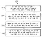
도 9는 중재적 기기 추적 장치(450)를 사용하기 위한 방법(500)을 설명한다. 단계(502)에서, 처리 시스템은 환자(P)의 해부학적 구조부의 모델을 수신한다. 모델은 부착된 기점 장치(460)에 의해 취해진 환자(P)의 이미지로부터 생성된다. 모델은 이미지 기준 프레임을 형성한다. 기점 표시부(466)는 모델에서 관측된다. 형상 센서 섬유(453)는 기준 고정구(462)에 결합되고, 형상 센서 섬유(470)는 기준 고정구(462)에 결합된다. 단계(504)에서, 형상 센서 정보는 처리를 위해 (형상 센서 섬유(470)의 기준 프레임의) 형상 센서 섬유(470)로부터 수신된다. 단계(506)에서, 형상 센서 정보는 처리를 위해 (형상 센서(453) 섬유의 기준 프레임의) 형상 센서 섬유(453)로부터 수신된다. 단계(508)에서, 형상 센서 섬유(353)의 원위 단부의 자세는 이미지 기준 프레임, 형상 센서(353)의 기준 프레임, 형상 센서(470)의 기준 프레임 사이의 상호 관계에 기초하여 한 이미지 기준 프레임에서 결정된다. 선택적으로, 가요성 본체(454)의 원위 단부의 자세에 대응하는 이미지 기준 프레임으로부터의 이미지가 표시된다. 이미지는 환자 모델로부터의 이미지에 중첩된 가요성 본체(454)의 원위 단부일 수 있다. 대안적으로, 이미지는 가요성 본체의 원위 단부로부터의 시점에 대응하는 환자 모델 내측으로부터의 시점일 수 있다.Figure 9 illustrates a
도 10은 본 개시 내용의 실시예에 따르는 중재적 기기 추적 시스템(550)을 설명한다. 추적 시스템(550)은 가요성 카테터 본체(554) 및 기기 본체(556)를 갖는 중재적 기기(552)를 포함한다. 광 섬유 형상 센서(553)는 중재적 기기(552)로부터 분리되고 중재적 기기로의 삽입에 맞는 크기를 갖는다. 추적 시스템(550)은 또한 센서 디바이스(558)를 포함한다. 센서 디바이스(558)는 기점 장치(560) 및 기준 본체(562)를 포함한다. 기점 장치(560)는 접착제 또는 다른 화학적 또는 기계적 고정 기구를 사용하여 환자(P)에 제거 가능하게 부착되는 표면(564)을 포함한다. 기점 장치(560)는 형광 투시법 또는 CT 등의 촬상 기술에 의해 관측되는 적어도 하나의 기점 표시부(566)를 포함한다. 기점 장치(560)는 기준 본체(562)의 정합 부분(570)과 결합하도록 구성된 센서 도킹 형상부(568)를 더 포함한다. 센서 도킹 형상부(568)는 기점 장치(560)를 기준 본체(562)에 제거 가능하게 연결하기 위해 하나 이상 리세스, 돌출부, 기계적 패스너, 접착 패스너, 자성 패스너 또는 다른 구성요소를 포함할 수 있다. 연결될 때, 센서 도킹 형상부(568) 및 정합 부분(570)은 기점 장치(560) 및 기준 본체(562)를 고정된, 미리 규정된 공간 관계에 유지한다.FIG. 10 illustrates an interventional
기준 본체(562)는 형상 센서 섬유(553)의 기준 부분(551)을 미리 규정된 기준 형상에 유지하도록 구성된 센서 홀더(572)를 포함한다. 이 실시예에서, 센서 홀더(572)는 형상 센서 섬유(553)를 수용하고 섬유를 기준 본체(562)에 대해 미리 규정된 형상 구성으로 유지하는 연속적인 와인딩 채널이다. 대체 실시예에서, 센서 홀더는 센서 섬유가 기준 본체에 대해 공지된, 미리 규정된 형상을 유지하도록 부착될 수 있는 일련의 개별 부착 지점일 수 있다. 기준 본체(562)는 센서 섬유(553)가 추적 시스템(550)의 다른 구성요소에 대한 연결을 종결하는 센서 연결 구성 요소(574)를 더 포함한다. 다양한 대체 실시예, 공지된 구성이 상술한 바와 같이 약간 가변적일 수 있다.The
추적 시스템(550)은 형상 센서 섬유(553)의 현재 형상을 결정하는데 사용되는 광을 생성 및 검출하는 호출 시스템(576)을 더 포함한다. 호출 시스템(576)은 또한 표시를 위해 의료인에게 반송되는 데이터를 처리할 수 있다. 호출 시스템(576)은 커넥터(578)를 포함한다. 섬유 링크(580)는 커넥터(582, 584) 사이에서 연장한다. 이 실시예에서, 섬유 링크(580)의 광 섬유는 감지되지 않고(즉, 섬유 링크의 형상이 호출되지 않음), 감지된 형상 센서(553)로부터 호출 시스템(576)으로 광학 정보를 이송하는 기능을 한다. 사용 시, 섬유 링크(580)의 커넥터(582)는 커넥터(574)에 연결되고 커넥터(584)는 커넥터(578)에 연결된다.The
사용 시, 기점 장치(560)는 환자(P)에 부착된다. 환자(P)의 수술 이전 또는 수술 중 촬상은 부착된 기점 장치(560)에 의해 수행된다. 기점 표시부(566)는 이미지에서 관측되고, 따라서 환자(P)의 해부 구조부에 대해 그리고 이미지에 의해 생성된 환자 해부 구조부의 임의의 2차원 또는 3차원 모델에 대해 고정된 기준을 제공한다. 중재적 시술을 개시하기 전에, 센서 섬유(553)는 가요성 카테터 본체(554)에 삽입된다. 기준 본체(562)는 기점 장치(560)에 결합되고, 도킹 형상부(568) 및 정합 부분(570)에 의해 기점 장치에 대해 미리 규정된 구성으로 보유된다. 따라서 연결되고, 형상 센서 섬유(553)의 기준 부분(551)은 기점 장치(560)에 대해 형상 센서 섬유의 근위 단부의 공지된 배향을 제공한다. 호출 시스템(576)은 원위 팁의 자세 및 가요성 카테터 본체(554)의 형상을 결정하기 위해 형상 센서 섬유(553)를 호출한다. 카테터 본체(554)에 대해 감지된 상대적 자세 및 형상 데이터는 형상 센서 섬유의 기준 부분(551)에 대해 공지되고, 기점 장치(560)에 등록된다. 따라서, 형상 센서 섬유의 기준 부분(551)에 대한 등록 정보를 갖는 카테터 본체(554)에 대한 상대적인 자세 및 형상 정보를 처리하는 것은 환자(P)에 대한 카테터 본체(554)의 자세 및 형상을 제공한다. 센서 섬유(553)로부터 정보를 처리하는 방법의 추가 세부 사항은 도 5에 대해 설명된 바와 유사하다.In use, the
이 실시예에서, 센서 섬유(553)는 가요성 카테터 본체로부터 분리될 수 있고, 따라서 센서 섬유(553)는 섬유(553)를 수용하는 크기의 루멘을 포함하는 기관지경 또는 다른 디바이스를 포함한 다른 유형의 기기와 함께 사용될 수 있다.In this embodiment, the
본 개시 내용의 시스템 및 방법이 폐의 연결된 기관지 통로들 내에서의 사용에 대해 설명되었지만, 이는 또한 대장, 소장, 신장, 뇌, 심장, 순환계 등을 포함한 다양한 해부학적 계통들 중 하나 내에서, 자연 또는 외과적으로 생성된 연결된 통로들을 거쳐, 운행 및 다른 조직들의 치료에 대해 적합하다. 본 개시 내용의 방법 및 실시예는 또한 비중재적 용도에 대해 적합하다.Although the systems and methods of this disclosure have been described for use in the bronchial passageways of the lungs, it is also contemplated that within the various anatomical systems, including the large intestine, small intestine, kidney, brain, heart, circulatory system, ≪ / RTI > or through surgically generated interconnected passages. The methods and embodiments of the present disclosure are also suitable for non-gravity applications.
본 발명의 실시예들 내의 하나 이상의 요소들은 제어 시스템(112)과 같은 컴퓨터 시스템의 처리기 상에서 실행하기 위해 소프트웨어 내에서 구현될 수 있다. 소프트웨어 내에서 구현될 때, 본 발명의 실시예들의 요소들은 본질적으로 필수적인 작업을 수행하기 위한 코드 세그먼트이다. 프로그램 또는 코드 세그먼트는 송신 매체 또는 통신 링크를 거쳐 반송파 내에서 실시되는 컴퓨터 데이터 신호에 의해 다운로드 되었을 수 있는 처리기 판독 가능 저장 매체 또는 디바이스 내에 저장될 수 있다. 처리기 판독 가능 저장 디바이스는 광학 매체, 반도체 매체, 및 자기 매체를 포함한 정보를 저장할 수 있는 임의의 매체를 포함할 수 있다. 처리기 판독 가능 저장 디바이스 예는 전자 회로; 반도체 디바이스, 반도체 메모리 디바이스, 리드 온리 메모리(ROM), 플래시 메모리, 소거할 수 있는 프로그램 가능한 리드 온리 메모리(EPROM); 플로피 디스켓, CD- ROM, 광학 디스크, 하드 디스크 또는 다른 저장 디바이스를 포함하고, 코드 세그먼트는 인터넷, 인트라넷, 등의 컴퓨터 네트워크를 통해 다운로드 될 수 있다.One or more elements within embodiments of the present invention may be implemented within software for execution on a processor of a computer system, such as
제시되는 처리 및 디스플레이는 임의의 특정 컴퓨터 또는 다른 장치에 고유하게 관련되지 않을 수 있음을 알아야 한다. 다양한 이러한 시스템에 대해 요구되는 구조는 청구범위에서 요소로서 출현할 것이다. 또한, 본 발명의 실시예는 임의의 특정 프로그래밍 언어를 참조하여 설명되지 않는다. 본 명세서에 기술된 본 발명의 교시를 구현하기 위해 각종 프로그래밍 언어가 이용될 수 있다는 것이 이해될 것이다.It should be noted that the processes and displays presented may not be inherently related to any particular computer or other device. The structures required for a variety of such systems will appear as elements in the claims. Furthermore, embodiments of the present invention are not described with reference to any particular programming language. It will be appreciated that various programming languages may be used to implement the teachings of the invention described herein.
본 발명의 소정의 예시적인 실시예가 설명되고 첨부된 도면에 도시되어 있지만, 다양한 다른 변형이 본 기술 분야의 통상의 기술자에게 명백할 수 있으므로, 그러한 실시예는 단지 예시적이며 광범위한 발명에 대해 제한적이지 않고, 본 발명의 실시예는 도시되고 설명된 특정 구성 및 배열로 제한되지 않음을 이해하여야 한다.While certain illustrative embodiments of the invention have been described and shown in the accompanying drawings, it is to be appreciated that various other modifications may be apparent to one of ordinary skill in the art, It should be understood that the embodiments of the present invention are not limited to the specific configurations and arrangements shown and described.
Claims (40)
Translated fromKorean상기 기점 장치는
센서 디바이스의 정합 부분과 정합하고 상기 정합 부분을 공지된 구성으로 유지하도록 구성된 센서 도킹 형상부,
적어도 하나의 촬상 가능한 기점 표시부; 및
환자의 해부 구조부에 대해 부착하도록 구성된 표면을 포함하는, 의료 추적 시스템.A medical tracking system comprising an originating device,
The starting point device
A sensor docking feature configured to mate with the mating portion of the sensor device and to maintain the mating portion in a known configuration,
At least one image pickup start point display section; And
And a surface configured to attach to a patient's anatomical structure.
상기 정합 부분을 포함하는 상기 센서 디바이스는 제1 형상 센서, 및 상기 제1 형상 센서를 센서 호출 시스템과 인터페이싱하는 센서 연결 구성요소를 포함하는, 의료 추적 시스템.The method according to claim 1,
Wherein the sensor device including the mating portion comprises a first shape sensor and a sensor connection component for interfacing the first shape sensor with a sensor calling system.
상기 제1 형상 센서가 내부에서 연장하는 세장형 가요성 기기를 더 포함하는, 의료 추적 시스템.3. The method of claim 2,
Wherein the first shape sensor extends within the elongate flexible device.
상기 제1 형상 센서는 세장형 가요성 기기에 고정되게 결합되는, 의료 추적 시스템.The method of claim 3,
Wherein the first shape sensor is fixedly coupled to the elongate flexible device.
상기 센서 호출 시스템은 제1 형상 센서로부터 정보를 수신하도록 구성된 처리기를 더 포함하는, 의료 추적 시스템.3. The method of claim 2,
Wherein the sensor calling system further comprises a processor configured to receive information from the first shape sensor.
상기 센서 호출 시스템 및 제1 형상 센서를 연결하여 상기 제1 형상 센서로부터 센서 호출 시스템까지 정보를 이송하도록 구성된 광 섬유 링크를 더 포함하는, 의료 추적 시스템.6. The method of claim 5,
Further comprising an optical fiber link configured to connect the sensor calling system and the first shape sensor to convey information from the first shape sensor to the sensor calling system.
상기 제1 형상 센서는 광 섬유 형상 센서를 포함하는, 의료 추적 시스템.3. The method of claim 2,
Wherein the first shape sensor comprises an optical fiber shape sensor.
상기 제1 형상 센서는 정합 부분을 포함하는, 의료 추적 시스템.3. The method of claim 2,
Wherein the first shape sensor comprises a mating portion.
상기 제1 형상 센서의 근위 단부를 고정된 자세로 보유하도록 구성된 제1 센서 어댑터를 포함하는 기준 고정구를 더 포함하는, 의료 추적 시스템.3. The method of claim 2,
Further comprising a reference fixture including a first sensor adapter configured to hold the proximal end of the first shape sensor in a fixed posture.
상기 기준 고정구는 제2 형상 센서의 근위 단부를 고정된 자세로 보유하도록 구성된 제2 센서 어댑터를 더 포함하고, 상기 기준 고정구는 제1 및 제2 형상 센서를 서로에 대해 고정된 관계로 유지하는, 의료 추적 시스템.10. The method of claim 9,
The reference fixture further comprises a second sensor adapter configured to hold the proximal end of the second shape sensor in a fixed posture, the reference fixture maintaining the first and second shape sensors in a fixed relationship with respect to each other, Medical Tracking System.
상기 제2 형상 센서의 원위 단부가 연장하는 세장형 가요성 기기를 더 포함하는, 의료 추적 시스템.11. The method of claim 10,
Further comprising a elongate flexible device extending a distal end of the second shape sensor.
상기 공지된 구성은 고정된, 미리 규정된 구성인, 의료 추적 시스템.The method according to claim 1,
Wherein the known configuration is a fixed, predefined configuration.
상기 센서 도킹 형상부는 정합 부분을 미리 규정된 구성으로 수용 및 유지하도록 구성된 와인딩 채널을 포함하는, 의료 추적 시스템.13. The method of claim 12,
Wherein the sensor docking feature comprises a winding channel configured to receive and maintain the mating portion in a predefined configuration.
상기 센서 도킹 형상부는 정합 부분을 미리 규정된 구성으로 유지하기 위해 정합 부분의 복수의 돌출부를 수용하도록 구성된 복수의 오목 형상부를 포함하는, 의료 추적 시스템.13. The method of claim 12,
Wherein the sensor docking feature comprises a plurality of recesses configured to receive a plurality of protrusions of the mating portion to maintain the mating portion in a predefined configuration.
상기 센서 도킹 형상부는 정합 부분을 미리 규정된 구성으로 유지하기 위해 정합 부분의 복수의 리세스를 수용하도록 구성된 복수의 돌출부를 포함하는, 의료 추적 시스템.13. The method of claim 12,
Wherein the sensor docking feature comprises a plurality of protrusions configured to receive a plurality of recesses of the mating portion to maintain the mating portion in a predefined configuration.
상기 공지된 구성은 약간 가변적인 구성인, 의료 추적 시스템.The method according to claim 1,
Wherein the known configuration is a slightly variable configuration.
약간 가변적인 구성은 삽입 거리인, 의료 추적 시스템.17. The method of claim 16,
A somewhat variable configuration is the insertion distance, a medical tracking system.
상기 센서 도킹 형상부와 센서 디바이스 사이의 자세 변화를 측정하는 변화 추적 시스템을 더 포함하는, 의료 추적 시스템.17. The method of claim 16,
Further comprising a change tracking system that measures a change in attitude between the sensor docking feature and the sensor device.
해부학적 구조부의 모델을 수신하는 단계로서, 상기 모델은 이미지 기준 프레임을 형성하고 적어도 하나의 기점 표시부의 이미지를 포함하는, 해부학적 구조부 모델 수신 단계,
적어도 하나의 기점 표시부를 포함하는 기점 장치가 제1 형상 센서 디바이스에 결합되어 제1 형상 센서 디바이스의 기준 부분이 적어도 하나의 기점 표시부에 대해 공지된 구성으로 유지될 때, 제1 형상 센서 디바이스의 기준 부분을 복수의 기점 표시부에 등록하는 단계,
제1 센서 기준 프레임 내의 제1 형상 센서 정보를 제1 형상 센서 디바이스의 제1 형상 센서로부터 수신하는 단계, 및
이미지 기준 프레임과 제1 센서 기준 프레임 사이의 상호 관계에 기초하여 이미지 기준 프레임 내의 제1 형상 센서의 자세를 결정하는 단계를 포함하는, 의료 기기 추적 방법.Medical device tracking method.
Receiving an anatomical structural part model, the model including an image reference frame and an image of at least one origin display,
When the starting point device including at least one starting point display portion is coupled to the first shape sensor device so that the reference portion of the first shape sensor device is held in a known configuration with respect to at least one starting point display portion, A step of registering a part in a plurality of starting point display sections,
Receiving first shape sensor information within a first sensor reference frame from a first shape sensor of a first shape sensor device, and
Determining the orientation of the first shape sensor within the image reference frame based on the correlation between the image reference frame and the first sensor reference frame.
제1 형상 센서의 자세에 대응하는 이미지 기준 프레임으로부터의 이미지를 표시하는 단계를 더 포함하는, 의료 기기 추적 방법.20. The method of claim 19,
Further comprising displaying an image from an image reference frame corresponding to a posture of the first shape sensor.
해부학적 구조부 모델을 수신하는 단계는 3차원 체적 이미지의 세트로부터 모델을 수신하는 단계를 포함하는, 의료 기기 추적 방법.20. The method of claim 19,
Wherein receiving an anatomical structural model comprises receiving a model from a set of three-dimensional volumetric images.
제1 형상 센서 정보를 수신하는 단계는 광 섬유 형상 센서로부터 생성된 정보를 수신하는 단계를 포함하는, 의료 기기 추적 방법.20. The method of claim 19,
Wherein receiving the first shape sensor information comprises receiving information generated from an optical fiber shape sensor.
제1 형상 센서 정보를 수신하는 단계는 해부학적 구조부와 함께 연장하는 세장형 가요성 기기에 결합된 제1 형상 센서로부터 제1 형상 센서 정보를 수신하는 단계를 포함하는, 의료 기기 추적 방법.20. The method of claim 19,
Wherein receiving the first shape sensor information comprises receiving first shape sensor information from a first shape sensor coupled to a elongated flexible device extending with the anatomical structure.
해부학적 구조부의 모델을 수신하는 단계로서, 상기 모델은 이미지 기준 프레임을 형성하고 적어도 하나의 기점 표시부의 모델을 포함하는, 해부학적 구조부 모델 수신 단계,
제1 기준 프레임 내의 제1 형상 센서 정보를 적어도 하나의 기점 표시부에 관해 공지된 구성으로 보유된 기준 부분을 포함하는 제1 형상 센서로부터 수신하는 단계,
제2 기준 프레임 내의 제2 형상 센서 정보를 해부학적 구조부 내에 위치된 제2 형상 센서로부터 수신하는 단계, 및
제1 기준 프레임, 제2 기준 프레임, 이미지 기준 프레임 사이의 상호 관계에 기초하여 이미지 기준 프레임 내의 제2 형상 센서의 자세를 결정하는 단계를 포함하는, 의료 기기 추적 방법.A method of tracking a medical device,
Receiving an anatomical structural part model, the model including an image reference frame and a model of at least one origin display,
Receiving first shape sensor information in a first reference frame from a first shape sensor comprising a reference portion held in a known configuration with respect to at least one origin display,
Receiving second shape sensor information in a second reference frame from a second shape sensor positioned within the anatomical structure, and
Determining an orientation of a second shape sensor in an image reference frame based on a correlation between a first reference frame, a second reference frame, and an image reference frame.
제2 형상 센서의 자세에 대응하는 이미지 기준 프레임으로부터의 이미지를 표시하는 단계를 더 포함하는, 의료 기기 추적 방법.25. The method of claim 24,
Further comprising displaying an image from an image reference frame corresponding to a posture of the second shape sensor.
해부학적 구조부의 모델을 수신하는 단계는 3차원 체적 이미지의 세트로부터 모델을 수신하는 단계를 포함하는, 의료 기기 추적 방법.25. The method of claim 24,
Wherein receiving a model of an anatomical structure comprises receiving a model from a set of three-dimensional volumetric images.
제1 형상 센서 정보를 수신하는 단계는 광 섬유 형상 센서로부터 생성된 정보를 수신하는 단계를 포함하는, 의료 기기 추적 방법.25. The method of claim 24,
Wherein receiving the first shape sensor information comprises receiving information generated from an optical fiber shape sensor.
제2 형상 센서 정보를 수신하는 단계는 광 섬유 형상 센서로부터 생성된 정보를 수신하는 단계를 포함하는, 의료 기기 추적 방법.25. The method of claim 24,
Wherein receiving the second shape sensor information comprises receiving information generated from an optical fiber shape sensor.
제2 형상 센서 정보를 수신하는 단계는 해부학적 구조부와 함께 연장하는 세장형 가요성 기기에 결합된 제2 형상 센서로부터 제2 형상 센서 정보를 수신하는 단계를 포함하는, 의료 기기 추적 방법.25. The method of claim 24,
Wherein receiving the second shape sensor information comprises receiving second shape sensor information from a second shape sensor coupled to a elongated flexible device extending with the anatomical structure.
해부학적 구조부를 나타내는 모델 데이터 세트를 저장하는 메모리이며, 상기 모델 데이터 세트는 하나 이상의 기점에 대해 공지된 관계로 해부학적 구조부에 대한 복수의 모델 데이터 지점을 갖는, 메모리, 및
해부학적 구조부와 상호 작용하는 기기 내의 광 섬유 센서로부터 형상 데이터를 수신하고 형상 데이터에 기초하여 기기에 모델 데이터 세트를 등록하도록 구성된 처리기로서, 상기 형상 데이터는 하나 이상의 기점에 대해 공지된 관계를 갖는, 처리기를 포함하는, 시스템.System,
A memory for storing a model data set representative of an anatomical structure, the model data set having a plurality of model data points for anatomical structures in a known relationship to one or more origin,
A processor configured to receive shape data from an optical fiber sensor in an appliance interacting with an anatomical structure and to register a set of model data to the appliance based on the shape data, the shape data having a known relationship to one or more origin, ≪ / RTI >
상기 처리기는 추가로 형상 데이터에 기초하여 모델 데이터 세트를 갱신하도록 구성되는, 시스템.31. The method of claim 30,
Wherein the processor is further configured to update the model data set based on the configuration data.
상기 처리기는 형상 데이터를 사용하여 기기의 자세를 생성하고 모델 데이터 세트를 자세에 맞추는 것에 의해 모델 데이터 세트를 갱신하도록 구성되는, 시스템.32. The method of claim 31,
Wherein the processor is configured to update the model data set by creating an attitude of the device using the shape data and orienting the model data set.
상기 처리기는 추가로 모델 데이터 세트로부터 생성된 모델 이미지 데이터 및 형상 데이터로부터 생성된 기기 이미지 데이터를 포함하는 이미지 데이터 세트를 생성하도록 구성되고, 기기 이미지 데이터는 모델 이미지 데이터에 등록되는, 시스템.31. The method of claim 30,
Wherein the processor is further configured to generate an image data set that includes device image data generated from model image data and shape data generated from a model data set and device image data is registered with the model image data.
상기 이미지 데이터 세트를 수신하고 모델 이미지 데이터에 중첩된 기기 이미지 데이터를 표시하는 디스플레이를 더 포함하는, 시스템.34. The method of claim 33,
Further comprising a display that receives the image data set and displays device image data superimposed on the model image data.
환자에의 부착을 위한 기점 장치, 및
광 섬유 형상 센서의 제1 부분을 기점 장치에 대해 미리 정해진 구성으로 유지하는 커플링을 포함하는, 의료 시스템.Medical system,
An origin device for attachment to a patient, and
And a coupling that maintains the first portion of the optical fiber shape sensor in a predetermined configuration with respect to the originating device.
상기 기점 장치는 기점 표시부, 및 의료 촬상 시스템에 의해 관측되는 기점 형상부 중 적어도 하나를 포함하는, 의료 시스템.36. The method of claim 35,
Wherein the starting point device comprises at least one of a starting point indicator, and a starting point feature observed by the medical imaging system.
상기 커플링은 광 섬유 형상 센서의 제1 부분을 미리 정해진 구성으로 유지하고 기점 장치와 제거 가능하게 정합하도록 구성된 기준 본체를 포함하는, 의료 시스템.36. The method of claim 35,
Wherein the coupling comprises a reference body configured to maintain a first portion of the optical fiber shape sensor in a predetermined configuration and to removably mate with an originating device.
상기 커플링은 광 섬유 형상 센서를 미리 정해진 구성으로 유지하기 위해 기점 장치의 하나 이상의 형상부를 포함하는, 의료 시스템.36. The method of claim 35,
Wherein the coupling includes at least one feature of the origin device to maintain the optical fiber shape sensor in a predetermined configuration.
환자의 해부학적 구조부와 상호 작용하는 기기를 더 포함하고, 광 섬유 형상 센서의 제2 부분이 기기에 결합되는, 의료 시스템.36. The method of claim 35,
Further comprising a device for interacting with an anatomical structure of the patient, wherein a second portion of the optical fiber shape sensor is coupled to the device.
상기 기점 장치에 등록된 해부학적 구조부의 모델을 수신하고, 기점 장치에 등록된 광 섬유 형상 센서의 제2 부분으로부터 형상 센서 데이터를 수신하고, 모델 및 형상 센서 데이터에 기초하여 해부학적 구조부에 대해 기기를 등록하도록 구성된 처리기를 더 포함하는, 의료 시스템.40. The method of claim 39,
Receiving the shape sensor data from the second part of the optical fiber shape sensor registered in the starting point device, and transmitting the shape sensor data to the anatomical structure part based on the model and shape sensor data, Further comprising: a processor configured to register the medical device.
Applications Claiming Priority (3)
| Application Number | Priority Date | Filing Date | Title |
|---|---|---|---|
| US201361799524P | 2013-03-15 | 2013-03-15 | |
| US61/799,524 | 2013-03-15 | ||
| PCT/US2014/023450WO2014150509A1 (en) | 2013-03-15 | 2014-03-11 | Shape sensor systems for tracking interventional instruments and methods of use |
Publications (2)
| Publication Number | Publication Date |
|---|---|
| KR20150132145Atrue KR20150132145A (en) | 2015-11-25 |
| KR102234145B1 KR102234145B1 (en) | 2021-03-31 |
Family
ID=51530425
Family Applications (1)
| Application Number | Title | Priority Date | Filing Date |
|---|---|---|---|
| KR1020157024762AActiveKR102234145B1 (en) | 2013-03-15 | 2014-03-11 | Shape sensor systems for tracking interventional instruments and methods of use |
Country Status (6)
| Country | Link |
|---|---|
| US (1) | US9918659B2 (en) |
| EP (2) | EP2968857B1 (en) |
| JP (3) | JP6363165B2 (en) |
| KR (1) | KR102234145B1 (en) |
| CN (2) | CN105050525B (en) |
| WO (1) | WO2014150509A1 (en) |
Cited By (2)
| Publication number | Priority date | Publication date | Assignee | Title |
|---|---|---|---|---|
| KR20230082051A (en)* | 2016-12-28 | 2023-06-08 | 아우리스 헬스, 인코포레이티드 | Apparatus for flexible instrument insertion |
| KR20230097437A (en)* | 2021-12-24 | 2023-07-03 | 한국과학기술연구원 | Method for measruing inserting length using shape of insertion device and insertion device for the same |
Families Citing this family (173)
| Publication number | Priority date | Publication date | Assignee | Title |
|---|---|---|---|---|
| US7728868B2 (en) | 2006-08-02 | 2010-06-01 | Inneroptic Technology, Inc. | System and method of providing real-time dynamic imagery of a medical procedure site using multiple modalities |
| US8218847B2 (en) | 2008-06-06 | 2012-07-10 | Superdimension, Ltd. | Hybrid registration method |
| US8641621B2 (en) | 2009-02-17 | 2014-02-04 | Inneroptic Technology, Inc. | Systems, methods, apparatuses, and computer-readable media for image management in image-guided medical procedures |
| US8690776B2 (en) | 2009-02-17 | 2014-04-08 | Inneroptic Technology, Inc. | Systems, methods, apparatuses, and computer-readable media for image guided surgery |
| US11464578B2 (en) | 2009-02-17 | 2022-10-11 | Inneroptic Technology, Inc. | Systems, methods, apparatuses, and computer-readable media for image management in image-guided medical procedures |
| US9254123B2 (en) | 2009-04-29 | 2016-02-09 | Hansen Medical, Inc. | Flexible and steerable elongate instruments with shape control and support elements |
| US20120071752A1 (en) | 2010-09-17 | 2012-03-22 | Sewell Christopher M | User interface and method for operating a robotic medical system |
| US20130030363A1 (en) | 2011-07-29 | 2013-01-31 | Hansen Medical, Inc. | Systems and methods utilizing shape sensing fibers |
| US10149720B2 (en) | 2013-03-08 | 2018-12-11 | Auris Health, Inc. | Method, apparatus, and a system for facilitating bending of an instrument in a surgical or medical robotic environment |
| US20140257095A1 (en)* | 2013-03-11 | 2014-09-11 | Volcano Corporation | Shape sensing interventional catheters and methods of use |
| US10314559B2 (en) | 2013-03-14 | 2019-06-11 | Inneroptic Technology, Inc. | Medical device guidance |
| US20140277334A1 (en) | 2013-03-14 | 2014-09-18 | Hansen Medical, Inc. | Active drives for robotic catheter manipulators |
| US9173713B2 (en) | 2013-03-14 | 2015-11-03 | Hansen Medical, Inc. | Torque-based catheter articulation |
| US11213363B2 (en) | 2013-03-14 | 2022-01-04 | Auris Health, Inc. | Catheter tension sensing |
| US9326822B2 (en) | 2013-03-14 | 2016-05-03 | Hansen Medical, Inc. | Active drives for robotic catheter manipulators |
| US20140276647A1 (en) | 2013-03-15 | 2014-09-18 | Hansen Medical, Inc. | Vascular remote catheter manipulator |
| US20140276936A1 (en) | 2013-03-15 | 2014-09-18 | Hansen Medical, Inc. | Active drive mechanism for simultaneous rotation and translation |
| US9408669B2 (en) | 2013-03-15 | 2016-08-09 | Hansen Medical, Inc. | Active drive mechanism with finite range of motion |
| US10376672B2 (en) | 2013-03-15 | 2019-08-13 | Auris Health, Inc. | Catheter insertion system and method of fabrication |
| US20140275810A1 (en)* | 2013-03-15 | 2014-09-18 | Inneroptic Technology, Inc. | Sensor mount |
| US11266466B2 (en) | 2013-07-29 | 2022-03-08 | Intuitive Surgical Operations, Inc. | Shape sensor systems with redundant sensing |
| US10046140B2 (en) | 2014-04-21 | 2018-08-14 | Hansen Medical, Inc. | Devices, systems, and methods for controlling active drive systems |
| US10569052B2 (en) | 2014-05-15 | 2020-02-25 | Auris Health, Inc. | Anti-buckling mechanisms for catheters |
| US10792464B2 (en) | 2014-07-01 | 2020-10-06 | Auris Health, Inc. | Tool and method for using surgical endoscope with spiral lumens |
| US9744335B2 (en) | 2014-07-01 | 2017-08-29 | Auris Surgical Robotics, Inc. | Apparatuses and methods for monitoring tendons of steerable catheters |
| US9561083B2 (en) | 2014-07-01 | 2017-02-07 | Auris Surgical Robotics, Inc. | Articulating flexible endoscopic tool with roll capabilities |
| US9603668B2 (en) | 2014-07-02 | 2017-03-28 | Covidien Lp | Dynamic 3D lung map view for tool navigation inside the lung |
| US9633431B2 (en) | 2014-07-02 | 2017-04-25 | Covidien Lp | Fluoroscopic pose estimation |
| US10791908B2 (en)* | 2014-08-25 | 2020-10-06 | Intuitive Surgical Operations, Inc. | Systems and methods for medical instrument force sensing |
| CN107072719A (en)* | 2014-09-08 | 2017-08-18 | 皇家飞利浦有限公司 | Optical shape sensing for instrument tracking in orthopedics |
| US9901406B2 (en) | 2014-10-02 | 2018-02-27 | Inneroptic Technology, Inc. | Affected region display associated with a medical device |
| WO2016061431A1 (en) | 2014-10-17 | 2016-04-21 | Intuitive Surgical Operations, Inc. | Systems and methods for reducing measurement error using optical fiber shape sensing |
| US9974525B2 (en) | 2014-10-31 | 2018-05-22 | Covidien Lp | Computed tomography enhanced fluoroscopic system, device, and method of utilizing the same |
| US10639007B2 (en) | 2014-12-02 | 2020-05-05 | Koninklijke Philips N.V. | Automatic tracking and registration of ultrasound probe using optical shape sensing without tip fixation |
| US10188467B2 (en) | 2014-12-12 | 2019-01-29 | Inneroptic Technology, Inc. | Surgical guidance intersection display |
| EP3247311B1 (en) | 2015-01-22 | 2020-03-18 | Koninklijke Philips N.V. | Endograft visualization with pre-integrated optical shape sensing attachments |
| US10939967B2 (en) | 2015-01-22 | 2021-03-09 | Koninklijke Philips N.V. | Robotic control of an endovascular deployment device with optical shape sensing feedback |
| US11819636B2 (en) | 2015-03-30 | 2023-11-21 | Auris Health, Inc. | Endoscope pull wire electrical circuit |
| CN114795471A (en) | 2015-04-06 | 2022-07-29 | 直观外科手术操作公司 | System and method for registration compensation in image-guided surgery |
| US10492871B2 (en) | 2015-05-01 | 2019-12-03 | Intuitive Surgical Operations, Inc. | Fiber management in medical instrument backend |
| CN107660134B (en) | 2015-05-22 | 2021-06-29 | 直观外科手术操作公司 | System and method for image-guided surgical recording |
| US9949700B2 (en) | 2015-07-22 | 2018-04-24 | Inneroptic Technology, Inc. | Medical device approaches |
| US10674982B2 (en) | 2015-08-06 | 2020-06-09 | Covidien Lp | System and method for local three dimensional volume reconstruction using a standard fluoroscope |
| US10716525B2 (en) | 2015-08-06 | 2020-07-21 | Covidien Lp | System and method for navigating to target and performing procedure on target utilizing fluoroscopic-based local three dimensional volume reconstruction |
| US10702226B2 (en) | 2015-08-06 | 2020-07-07 | Covidien Lp | System and method for local three dimensional volume reconstruction using a standard fluoroscope |
| CN108348133B (en) | 2015-09-09 | 2020-11-13 | 奥瑞斯健康公司 | Instrument Manipulators for Surgical Robotic Systems |
| CN108024693B (en)* | 2015-09-10 | 2021-07-09 | 直观外科手术操作公司 | Systems and methods for utilizing tracking in image-guided medical procedures |
| CN108135530B (en)* | 2015-10-02 | 2023-01-17 | 皇家飞利浦有限公司 | A hub for device navigation utilizing optical shape-sensing guidewires |
| US9955986B2 (en) | 2015-10-30 | 2018-05-01 | Auris Surgical Robotics, Inc. | Basket apparatus |
| US9949749B2 (en) | 2015-10-30 | 2018-04-24 | Auris Surgical Robotics, Inc. | Object capture with a basket |
| US10231793B2 (en) | 2015-10-30 | 2019-03-19 | Auris Health, Inc. | Object removal through a percutaneous suction tube |
| US9947091B2 (en)* | 2015-11-16 | 2018-04-17 | Biosense Webster (Israel) Ltd. | Locally applied transparency for a CT image |
| CN108472082B (en)* | 2015-12-29 | 2021-08-10 | 皇家飞利浦有限公司 | Registration system for medical navigation and method of operation thereof |
| EP3397184A1 (en)* | 2015-12-29 | 2018-11-07 | Koninklijke Philips N.V. | System, control unit and method for control of a surgical robot |
| EP4375934A3 (en)* | 2016-02-12 | 2024-07-31 | Intuitive Surgical Operations, Inc. | Systems and methods of pose estimation and calibration of perspective imaging system in image guided surgery |
| US9675319B1 (en) | 2016-02-17 | 2017-06-13 | Inneroptic Technology, Inc. | Loupe display |
| US20170239013A1 (en)* | 2016-02-24 | 2017-08-24 | General Electric Company | Patient reference assembly for an electromagnetic navigation system |
| WO2017157592A1 (en)* | 2016-03-15 | 2017-09-21 | Koninklijke Philips N.V. | Fiber-optic realshape sensing feeding tube |
| US10454347B2 (en) | 2016-04-29 | 2019-10-22 | Auris Health, Inc. | Compact height torque sensing articulation axis assembly |
| WO2017223350A1 (en)* | 2016-06-23 | 2017-12-28 | Intuitive Surgical Operations, Inc. | Removing light energy from a fiber cladding |
| CN109982656B (en)* | 2016-06-30 | 2022-04-08 | 皇家飞利浦有限公司 | Medical navigation system employing optical position sensing and method of operation thereof |
| US10463439B2 (en) | 2016-08-26 | 2019-11-05 | Auris Health, Inc. | Steerable catheter with shaft load distributions |
| KR20230096148A (en) | 2016-08-31 | 2023-06-29 | 아우리스 헬스, 인코포레이티드 | Length conservative surgical instrument |
| US10278778B2 (en) | 2016-10-27 | 2019-05-07 | Inneroptic Technology, Inc. | Medical device navigation using a virtual 3D space |
| US10244926B2 (en) | 2016-12-28 | 2019-04-02 | Auris Health, Inc. | Detecting endolumenal buckling of flexible instruments |
| US11793579B2 (en) | 2017-02-22 | 2023-10-24 | Covidien Lp | Integration of multiple data sources for localization and navigation |
| US10839956B2 (en)* | 2017-03-03 | 2020-11-17 | University of Maryland Medical Center | Universal device and method to integrate diagnostic testing into treatment in real-time |
| JP6787211B2 (en)* | 2017-03-24 | 2020-11-18 | トヨタ自動車株式会社 | Filament winding device |
| EP3606592B1 (en) | 2017-04-07 | 2025-01-08 | Bard Access Systems, Inc. | Optical fiber-based medical device tracking and monitoring system |
| KR102576296B1 (en) | 2017-05-17 | 2023-09-08 | 아우리스 헬스, 인코포레이티드 | Interchangeable working channels |
| WO2018222834A1 (en)* | 2017-05-31 | 2018-12-06 | Abb Schweiz Ag | Robot system for real-time inspection of switchgear |
| EP3642646B1 (en)* | 2017-06-19 | 2025-02-19 | Koninklijke Philips N.V. | Interleaved imaging and tracking sequences for ultrasound-based instrument tracking |
| US11026758B2 (en) | 2017-06-28 | 2021-06-08 | Auris Health, Inc. | Medical robotics systems implementing axis constraints during actuation of one or more motorized joints |
| US10699448B2 (en) | 2017-06-29 | 2020-06-30 | Covidien Lp | System and method for identifying, marking and navigating to a target using real time two dimensional fluoroscopic data |
| WO2019027922A1 (en) | 2017-07-31 | 2019-02-07 | Intuitive Surgical Operations, Inc. | Systems and methods for safe operation of a device |
| US11259879B2 (en) | 2017-08-01 | 2022-03-01 | Inneroptic Technology, Inc. | Selective transparency to assist medical device navigation |
| EP3694412A4 (en) | 2017-10-10 | 2021-08-18 | Covidien LP | SYSTEM AND METHOD FOR IDENTIFYING AND MARKING A TARGET IN A FLUOROSCOPIC THREE-DIMENSIONAL RECONSTRUCTION |
| US11179203B2 (en) | 2017-10-26 | 2021-11-23 | Biosense Webster (Israel) Ltd. | Position-tracking-enabling connector for an ear-nose-throat (ENT) tool |
| KR102577474B1 (en) | 2017-11-21 | 2023-09-12 | 인튜어티브 서지컬 오퍼레이션즈 인코포레이티드 | System and method for master/tool matching and control for intuitive movement |
| CN111770736A (en) | 2017-12-11 | 2020-10-13 | 奥瑞斯健康公司 | Systems and methods for instrument-based insertion architectures |
| US11510736B2 (en) | 2017-12-14 | 2022-11-29 | Auris Health, Inc. | System and method for estimating instrument location |
| US11484365B2 (en) | 2018-01-23 | 2022-11-01 | Inneroptic Technology, Inc. | Medical image guidance |
| US10893842B2 (en) | 2018-02-08 | 2021-01-19 | Covidien Lp | System and method for pose estimation of an imaging device and for determining the location of a medical device with respect to a target |
| US10930064B2 (en) | 2018-02-08 | 2021-02-23 | Covidien Lp | Imaging reconstruction system and method |
| US10905498B2 (en) | 2018-02-08 | 2021-02-02 | Covidien Lp | System and method for catheter detection in fluoroscopic images and updating displayed position of catheter |
| CN117017505A (en) | 2018-03-28 | 2023-11-10 | 奥瑞斯健康公司 | Composite instrument and robotic system |
| KR102712920B1 (en) | 2018-06-27 | 2024-10-07 | 아우리스 헬스, 인코포레이티드 | Alignment and attachment systems for medical devices |
| US11705238B2 (en) | 2018-07-26 | 2023-07-18 | Covidien Lp | Systems and methods for providing assistance during surgery |
| US11071591B2 (en) | 2018-07-26 | 2021-07-27 | Covidien Lp | Modeling a collapsed lung using CT data |
| WO2020033318A1 (en) | 2018-08-07 | 2020-02-13 | Auris Health, Inc. | Combining strain-based shape sensing with catheter control |
| CN112804933B (en) | 2018-09-26 | 2024-10-18 | 奥瑞斯健康公司 | Articulating medical device |
| US11944388B2 (en) | 2018-09-28 | 2024-04-02 | Covidien Lp | Systems and methods for magnetic interference correction |
| WO2020069080A1 (en) | 2018-09-28 | 2020-04-02 | Auris Health, Inc. | Devices, systems, and methods for manually and robotically driving medical instruments |
| US11897127B2 (en) | 2018-10-22 | 2024-02-13 | Intuitive Surgical Operations, Inc. | Systems and methods for master/tool registration and control for intuitive motion |
| US11877806B2 (en) | 2018-12-06 | 2024-01-23 | Covidien Lp | Deformable registration of computer-generated airway models to airway trees |
| US11045075B2 (en) | 2018-12-10 | 2021-06-29 | Covidien Lp | System and method for generating a three-dimensional model of a surgical site |
| US11801113B2 (en) | 2018-12-13 | 2023-10-31 | Covidien Lp | Thoracic imaging, distance measuring, and notification system and method |
| US11617493B2 (en) | 2018-12-13 | 2023-04-04 | Covidien Lp | Thoracic imaging, distance measuring, surgical awareness, and notification system and method |
| WO2020139973A1 (en)* | 2018-12-28 | 2020-07-02 | Auris Health, Inc. | Medical instrument with articulable segment |
| US11357593B2 (en) | 2019-01-10 | 2022-06-14 | Covidien Lp | Endoscopic imaging with augmented parallax |
| EP3682836A1 (en)* | 2019-01-21 | 2020-07-22 | Koninklijke Philips N.V. | Assisting in moving an insertion element within an object |
| US11625825B2 (en) | 2019-01-30 | 2023-04-11 | Covidien Lp | Method for displaying tumor location within endoscopic images |
| US11925333B2 (en) | 2019-02-01 | 2024-03-12 | Covidien Lp | System for fluoroscopic tracking of a catheter to update the relative position of a target and the catheter in a 3D model of a luminal network |
| US11564751B2 (en) | 2019-02-01 | 2023-01-31 | Covidien Lp | Systems and methods for visualizing navigation of medical devices relative to targets |
| US11744643B2 (en) | 2019-02-04 | 2023-09-05 | Covidien Lp | Systems and methods facilitating pre-operative prediction of post-operative tissue function |
| US12096993B2 (en)* | 2019-02-28 | 2024-09-24 | Koninklijke Philips N.V. | Feedback continuous positioning control of end-effectors |
| CN109793489A (en)* | 2019-03-26 | 2019-05-24 | 上海优益基医用材料有限公司 | visual positioning catheter |
| US11617627B2 (en) | 2019-03-29 | 2023-04-04 | Auris Health, Inc. | Systems and methods for optical strain sensing in medical instruments |
| US11819285B2 (en) | 2019-04-05 | 2023-11-21 | Covidien Lp | Magnetic interference detection systems and methods |
| CN112206400B (en)* | 2019-07-12 | 2025-02-28 | 巴德阿克塞斯系统股份有限公司 | Catheter tracking and placement system including a light emitting diode array |
| US12089902B2 (en) | 2019-07-30 | 2024-09-17 | Coviden Lp | Cone beam and 3D fluoroscope lung navigation |
| EP4013338A4 (en) | 2019-08-12 | 2023-08-30 | Bard Access Systems, Inc. | SHAPE DETECTION SYSTEMS AND METHODS FOR MEDICAL DEVICES |
| US11896330B2 (en) | 2019-08-15 | 2024-02-13 | Auris Health, Inc. | Robotic medical system having multiple medical instruments |
| WO2021028883A1 (en) | 2019-08-15 | 2021-02-18 | Auris Health, Inc. | Medical device having multiple bending sections |
| US11269173B2 (en) | 2019-08-19 | 2022-03-08 | Covidien Lp | Systems and methods for displaying medical video images and/or medical 3D models |
| US12059281B2 (en) | 2019-08-19 | 2024-08-13 | Covidien Lp | Systems and methods of fluoro-CT imaging for initial registration |
| US11931111B2 (en) | 2019-09-09 | 2024-03-19 | Covidien Lp | Systems and methods for providing surgical guidance |
| US11864935B2 (en) | 2019-09-09 | 2024-01-09 | Covidien Lp | Systems and methods for pose estimation of a fluoroscopic imaging device and for three-dimensional imaging of body structures |
| US11627924B2 (en) | 2019-09-24 | 2023-04-18 | Covidien Lp | Systems and methods for image-guided navigation of percutaneously-inserted devices |
| US11737845B2 (en) | 2019-09-30 | 2023-08-29 | Auris Inc. | Medical instrument with a capstan |
| CN110638659A (en)* | 2019-11-01 | 2020-01-03 | 广州驭林医药科技有限公司 | Gastrointestinal tube nutrition system |
| EP4061272A4 (en) | 2019-11-25 | 2023-11-22 | Bard Access Systems, Inc. | Shape-sensing systems with filters and methods thereof |
| CN112826497B (en) | 2019-11-25 | 2025-09-09 | 巴德阿克塞斯系统股份有限公司 | Optical tip tracking system and method thereof |
| US20230010631A1 (en)* | 2019-12-09 | 2023-01-12 | Deutsches Krebsforschungszentrum | Kit for a fiducial marker-based registration of preinterventional image data to an intra-interventional scene |
| US12102298B2 (en) | 2019-12-10 | 2024-10-01 | Covidien Lp | Lymphatic system tracking |
| EP4084724A4 (en) | 2019-12-31 | 2023-12-27 | Auris Health, Inc. | ADVANCED BASKET DRIVE MODE |
| CN114901188A (en) | 2019-12-31 | 2022-08-12 | 奥瑞斯健康公司 | Dynamic pulley system |
| US11380060B2 (en) | 2020-01-24 | 2022-07-05 | Covidien Lp | System and method for linking a segmentation graph to volumetric data |
| US11847730B2 (en) | 2020-01-24 | 2023-12-19 | Covidien Lp | Orientation detection in fluoroscopic images |
| CN111265299B (en)* | 2020-02-19 | 2023-08-18 | 上海理工大学 | Operation navigation system based on optical fiber shape sensing |
| CN215461207U (en) | 2020-02-28 | 2022-01-11 | 巴德阿克塞斯系统股份有限公司 | Catheter and medical instrument monitoring system |
| US11474310B2 (en) | 2020-02-28 | 2022-10-18 | Bard Access Systems, Inc. | Optical connection systems and methods thereof |
| CN111580230A (en)* | 2020-03-02 | 2020-08-25 | 华中科技大学 | Flexible optical fiber, preparation method and drivable laser scalpel based on the same |
| CN113332561A (en) | 2020-03-03 | 2021-09-03 | 巴德阿克塞斯系统股份有限公司 | System and method for optical shape sensing and electrical signal conduction |
| WO2021202589A1 (en) | 2020-03-30 | 2021-10-07 | Bard Access Systems, Inc. | Optical and electrical diagnostic systems and methods thereof |
| US12064191B2 (en) | 2020-06-03 | 2024-08-20 | Covidien Lp | Surgical tool navigation using sensor fusion |
| CN113842536A (en) | 2020-06-26 | 2021-12-28 | 巴德阿克塞斯系统股份有限公司 | Dislocation detection system |
| WO2022005870A1 (en) | 2020-06-29 | 2022-01-06 | Bard Access Systems, Inc. | Automatic dimensional frame reference for fiber optic |
| WO2022011287A1 (en) | 2020-07-10 | 2022-01-13 | Bard Access Systems, Inc. | Continuous fiber optic functionality monitoring and self-diagnostic reporting system |
| US11950950B2 (en) | 2020-07-24 | 2024-04-09 | Covidien Lp | Zoom detection and fluoroscope movement detection for target overlay |
| WO2022031613A1 (en) | 2020-08-03 | 2022-02-10 | Bard Access Systems, Inc. | Bragg grated fiber optic fluctuation sensing and monitoring system |
| US12383352B2 (en) | 2020-08-13 | 2025-08-12 | Covidien Lp | Endoluminal robotic (ELR) systems and methods |
| US12256923B2 (en) | 2020-08-13 | 2025-03-25 | Covidien Lp | Endoluminal robotic systems and methods for suturing |
| US12161309B2 (en) | 2020-09-24 | 2024-12-10 | Covidien Lp | Articulating mechanism for the laparoscopic ablation device for blunt dissection |
| WO2022067101A1 (en) | 2020-09-25 | 2022-03-31 | Bard Access Systems, Inc. | Minimum catheter length tool |
| CN114246583A (en) | 2020-09-25 | 2022-03-29 | 巴德阿克塞斯系统股份有限公司 | Fiber Optic Oximetry Systems for Detection and Confirmation |
| CN114344514A (en) | 2020-10-13 | 2022-04-15 | 巴德阿克塞斯系统股份有限公司 | Disinfection enclosure for fiber optic connectors and method thereof |
| CN114518075A (en) | 2020-11-18 | 2022-05-20 | 巴德阿克塞斯系统股份有限公司 | fiber optic stylet holder |
| WO2022115624A1 (en) | 2020-11-24 | 2022-06-02 | Bard Access Systems, Inc. | Steerable fiber optic shape sensing enabled elongated medical instrument |
| WO2022150411A1 (en)* | 2021-01-06 | 2022-07-14 | Bard Access Systems, Inc. | Needle guidance using fiber optic shape sensing |
| US12426954B2 (en) | 2021-01-26 | 2025-09-30 | Bard Access Systems, Inc. | Fiber optic shape sensing system associated with port placement |
| US12349983B2 (en) | 2021-03-05 | 2025-07-08 | Bard Access Systems, Inc. | Systems and methods for ultrasound-and-bioimpedance-based guidance of medical devices |
| CN112914731A (en)* | 2021-03-08 | 2021-06-08 | 上海交通大学 | Interventional robot contactless teleoperation system based on augmented reality and calibration method |
| CN115886783A (en)* | 2021-09-30 | 2023-04-04 | 巴德阿克塞斯系统股份有限公司 | Shape sensing reference frame |
| CN115969409A (en)* | 2021-10-14 | 2023-04-18 | 巴德阿克塞斯系统股份有限公司 | Optical fiber ultrasonic probe |
| US12419694B2 (en) | 2021-10-25 | 2025-09-23 | Bard Access Systems, Inc. | Reference plane for medical device placement |
| TWI850880B (en) | 2021-11-30 | 2024-08-01 | 美商安督奎斯特機器人公司 | Disposable end effectors, medical device, and operating method thereof |
| EP4440481A1 (en) | 2021-11-30 | 2024-10-09 | Endoquest Robotics, Inc. | Barrier drape adapters for robotic surgical systems |
| TWI838986B (en) | 2021-11-30 | 2024-04-11 | 美商安督奎斯特機器人公司 | Patient console, robotic surgical system having the same, and method for performing the same |
| TWI835436B (en) | 2021-11-30 | 2024-03-11 | 美商安督奎斯特機器人公司 | Steerable overtube assemblies for robotic surgical systems, control assemblies and method thereof |
| WO2023101948A1 (en) | 2021-11-30 | 2023-06-08 | Endoquest, Inc. | Master control systems for robotic surgical systems |
| WO2023101974A1 (en) | 2021-11-30 | 2023-06-08 | Endoquest Robotics, Inc. | Force transmission systems for robotically controlled medical devices |
| US12303220B2 (en) | 2022-01-26 | 2025-05-20 | Covidien Lp | Autonomous endobronchial access with an EM guided catheter |
| US12318149B2 (en) | 2022-03-08 | 2025-06-03 | Bard Access Systems, Inc. | Medical shape sensing devices and systems |
| US12426956B2 (en) | 2022-03-16 | 2025-09-30 | Bard Access Systems, Inc. | Medical system and method for monitoring medical device insertion and illumination patterns |
| US12089815B2 (en) | 2022-03-17 | 2024-09-17 | Bard Access Systems, Inc. | Fiber optic medical systems and devices with atraumatic tip |
| US12207967B2 (en) | 2022-04-20 | 2025-01-28 | Bard Access Systems, Inc. | Ultrasound imaging system |
| US12343117B2 (en) | 2022-06-28 | 2025-07-01 | Bard Access Systems, Inc. | Fiber optic medical systems and methods for identifying blood vessels |
| US12349984B2 (en) | 2022-06-29 | 2025-07-08 | Bard Access Systems, Inc. | System, method, and apparatus for improved confirm of an anatomical position of a medical instrument |
| US12257082B2 (en) | 2022-06-30 | 2025-03-25 | Covidien Lp | Cone beam computed tomography integration for creating a navigation pathway to a target in the lung and method of navigating to the target |
| CN119584912A (en)* | 2022-07-21 | 2025-03-07 | 直观外科手术操作公司 | Shape positioning flexible device |
| CN115300750A (en)* | 2022-07-28 | 2022-11-08 | 同济大学 | Intelligent PCI (peripheral component interconnect) surgical catheter, and control system and control method thereof |
| WO2025019569A1 (en)* | 2023-07-18 | 2025-01-23 | Intuitive Surgical Operations, Inc. | Intra-operative imaging to robotic-assisted navigation |
Citations (3)
| Publication number | Priority date | Publication date | Assignee | Title |
|---|---|---|---|---|
| US20090137952A1 (en)* | 2007-08-14 | 2009-05-28 | Ramamurthy Bhaskar S | Robotic instrument systems and methods utilizing optical fiber sensor |
| WO2012101563A2 (en)* | 2011-01-27 | 2012-08-02 | Koninklijke Philips Electronics N.V. | Integration of fiber optic shape sensing within an nterventional environment |
| US20130028554A1 (en)* | 2011-07-29 | 2013-01-31 | Hansen Medical, Inc. | Apparatus and methods for fiber integration and registration |
Family Cites Families (31)
| Publication number | Priority date | Publication date | Assignee | Title |
|---|---|---|---|---|
| CA2678625A1 (en)* | 1992-09-23 | 1994-03-31 | St. Jude Medical, Atrial Fibrillation Division, Inc. | Endocardial mapping system |
| JP3135068B2 (en)* | 1994-09-15 | 2001-02-13 | ビジュアリゼイション テクノロジー インコーポレイテッド | Position tracking and image generation system for medical applications using a reference unit fixed to the patient's head |
| WO1998036236A1 (en) | 1997-02-13 | 1998-08-20 | Super Dimension Ltd. | Six-degree tracking system |
| GB9713018D0 (en) | 1997-06-20 | 1997-08-27 | Secr Defence | Optical fibre bend sensor |
| US6381485B1 (en)* | 1999-10-28 | 2002-04-30 | Surgical Navigation Technologies, Inc. | Registration of human anatomy integrated for electromagnetic localization |
| CA2325036A1 (en)* | 1999-10-29 | 2001-04-29 | Advanced Sensor Technology, Llc | Optical fiber navigation system |
| US7747312B2 (en)* | 2000-01-04 | 2010-06-29 | George Mason Intellectual Properties, Inc. | System and method for automatic shape registration and instrument tracking |
| US8241274B2 (en) | 2000-01-19 | 2012-08-14 | Medtronic, Inc. | Method for guiding a medical device |
| US20020058864A1 (en)* | 2000-11-13 | 2002-05-16 | Mansfield James R. | Reduction of spectral site to site variation |
| US6846286B2 (en)* | 2001-05-22 | 2005-01-25 | Pentax Corporation | Endoscope system |
| US7787934B2 (en)* | 2002-07-29 | 2010-08-31 | Medtronic, Inc. | Fiducial marker devices, tools, and methods |
| US7781724B2 (en) | 2004-07-16 | 2010-08-24 | Luna Innovations Incorporated | Fiber optic position and shape sensing device and method relating thereto |
| US7772541B2 (en) | 2004-07-16 | 2010-08-10 | Luna Innnovations Incorporated | Fiber optic position and/or shape sensing based on rayleigh scatter |
| US20060013523A1 (en) | 2004-07-16 | 2006-01-19 | Luna Innovations Incorporated | Fiber optic position and shape sensing device and method relating thereto |
| US7751868B2 (en)* | 2004-11-12 | 2010-07-06 | Philips Electronics Ltd | Integrated skin-mounted multifunction device for use in image-guided surgery |
| US8611983B2 (en) | 2005-01-18 | 2013-12-17 | Philips Electronics Ltd | Method and apparatus for guiding an instrument to a target in the lung |
| US9204830B2 (en)* | 2005-04-15 | 2015-12-08 | Surgisense Corporation | Surgical instruments with sensors for detecting tissue properties, and system using such instruments |
| JP4914574B2 (en)* | 2005-04-18 | 2012-04-11 | オリンパスメディカルシステムズ株式会社 | Endoscope shape detection device |
| US9526587B2 (en) | 2008-12-31 | 2016-12-27 | Intuitive Surgical Operations, Inc. | Fiducial marker design and detection for locating surgical instrument in images |
| US7930065B2 (en) | 2005-12-30 | 2011-04-19 | Intuitive Surgical Operations, Inc. | Robotic surgery system including position sensors using fiber bragg gratings |
| GB2437250C (en)* | 2006-04-18 | 2012-08-15 | Iti Scotland Ltd | Method and system for monitoring the condition of livestock |
| WO2008076910A1 (en)* | 2006-12-15 | 2008-06-26 | The Board Of Trustees Of The Leland Stanford Junior University | Image mosaicing systems and methods |
| US8175677B2 (en)* | 2007-06-07 | 2012-05-08 | MRI Interventions, Inc. | MRI-guided medical interventional systems and methods |
| EP2240111B1 (en)* | 2008-06-18 | 2019-07-24 | Mako Surgical Corp. | Fiber optic tracking system |
| US7720322B2 (en)* | 2008-06-30 | 2010-05-18 | Intuitive Surgical, Inc. | Fiber optic shape sensor |
| US8183520B2 (en)* | 2009-11-13 | 2012-05-22 | Intuitive Surgical Operations, Inc. | Optical fiber shape sensor calibration |
| US8657809B2 (en)* | 2010-09-29 | 2014-02-25 | Stryker Leibinger Gmbh & Co., Kg | Surgical navigation system |
| EP2667774A1 (en)* | 2011-01-27 | 2013-12-04 | Koninklijke Philips N.V. | Shape sensing device-specific information storage and retrieval |
| US10820830B2 (en)* | 2011-01-28 | 2020-11-03 | Koninklijke Philips N.V. | Reference markers for launch point identification in optical shape sensing systems |
| US8900131B2 (en) | 2011-05-13 | 2014-12-02 | Intuitive Surgical Operations, Inc. | Medical system providing dynamic registration of a model of an anatomical structure for image-guided surgery |
| US9675304B2 (en)* | 2011-06-27 | 2017-06-13 | Koninklijke Philips N.V. | Live 3D angiogram using registration of a surgical tool curve to an X-ray image |
- 2014
- 2014-03-11CNCN201480014713.1Apatent/CN105050525B/enactiveActive
- 2014-03-11EPEP14769738.7Apatent/EP2968857B1/enactiveActive
- 2014-03-11JPJP2016501237Apatent/JP6363165B2/enactiveActive
- 2014-03-11EPEP22155027.0Apatent/EP4049706A1/enactivePending
- 2014-03-11WOPCT/US2014/023450patent/WO2014150509A1/enactiveApplication Filing
- 2014-03-11USUS14/204,807patent/US9918659B2/enactiveActive
- 2014-03-11KRKR1020157024762Apatent/KR102234145B1/enactiveActive
- 2014-03-11CNCN201810733962.6Apatent/CN108784702B/enactiveActive
- 2018
- 2018-06-27JPJP2018121615Apatent/JP6620191B2/enactiveActive
- 2019
- 2019-11-18JPJP2019207614Apatent/JP6976303B2/enactiveActive
Patent Citations (3)
| Publication number | Priority date | Publication date | Assignee | Title |
|---|---|---|---|---|
| US20090137952A1 (en)* | 2007-08-14 | 2009-05-28 | Ramamurthy Bhaskar S | Robotic instrument systems and methods utilizing optical fiber sensor |
| WO2012101563A2 (en)* | 2011-01-27 | 2012-08-02 | Koninklijke Philips Electronics N.V. | Integration of fiber optic shape sensing within an nterventional environment |
| US20130028554A1 (en)* | 2011-07-29 | 2013-01-31 | Hansen Medical, Inc. | Apparatus and methods for fiber integration and registration |
Cited By (2)
| Publication number | Priority date | Publication date | Assignee | Title |
|---|---|---|---|---|
| KR20230082051A (en)* | 2016-12-28 | 2023-06-08 | 아우리스 헬스, 인코포레이티드 | Apparatus for flexible instrument insertion |
| KR20230097437A (en)* | 2021-12-24 | 2023-07-03 | 한국과학기술연구원 | Method for measruing inserting length using shape of insertion device and insertion device for the same |
Also Published As
| Publication number | Publication date |
|---|---|
| WO2014150509A1 (en) | 2014-09-25 |
| US20140275997A1 (en) | 2014-09-18 |
| EP4049706A1 (en) | 2022-08-31 |
| CN108784702A (en) | 2018-11-13 |
| CN105050525A (en) | 2015-11-11 |
| JP6363165B2 (en) | 2018-07-25 |
| JP6976303B2 (en) | 2021-12-08 |
| JP2018143817A (en) | 2018-09-20 |
| US9918659B2 (en) | 2018-03-20 |
| EP2968857A1 (en) | 2016-01-20 |
| EP2968857B1 (en) | 2022-05-04 |
| KR102234145B1 (en) | 2021-03-31 |
| JP2016515862A (en) | 2016-06-02 |
| CN105050525B (en) | 2018-07-31 |
| JP2020022865A (en) | 2020-02-13 |
| CN108784702B (en) | 2021-11-12 |
| JP6620191B2 (en) | 2019-12-11 |
| EP2968857A4 (en) | 2016-11-02 |
Similar Documents
| Publication | Publication Date | Title |
|---|---|---|
| JP6976303B2 (en) | Shape sensor system for tracking intervention equipment and how to use this system | |
| US12408891B2 (en) | Systems and methods for interventional procedure planning | |
| EP3503834B1 (en) | Systems for monitoring patient motion during a medical procedure | |
| KR102279975B1 (en) | Shape sensor systems with redundant sensing | |
| KR102214145B1 (en) | Systems and methods for registration of a medical device using a reduced search space | |
| KR102620057B1 (en) | Systems and methods for adaptive input mapping | |
| KR20190045380A (en) | Systems and methods for instrument buckling detection | |
| CN108024693A (en) | The system and method for tracking are utilized in image guided medical program | |
| KR20210156301A (en) | Systems and methods for non-rigid deformation of tissue for virtual navigation of interventional tools |
Legal Events
| Date | Code | Title | Description |
|---|---|---|---|
| PA0105 | International application | Patent event date:20150910 Patent event code:PA01051R01D Comment text:International Patent Application | |
| PG1501 | Laying open of application | ||
| A201 | Request for examination | ||
| PA0201 | Request for examination | Patent event code:PA02012R01D Patent event date:20190226 Comment text:Request for Examination of Application | |
| E902 | Notification of reason for refusal | ||
| PE0902 | Notice of grounds for rejection | Comment text:Notification of reason for refusal Patent event date:20200714 Patent event code:PE09021S01D | |
| E701 | Decision to grant or registration of patent right | ||
| PE0701 | Decision of registration | Patent event code:PE07011S01D Comment text:Decision to Grant Registration Patent event date:20210113 | |
| GRNT | Written decision to grant | ||
| PR0701 | Registration of establishment | Comment text:Registration of Establishment Patent event date:20210325 Patent event code:PR07011E01D | |
| PR1002 | Payment of registration fee | Payment date:20210326 End annual number:3 Start annual number:1 | |
| PG1601 | Publication of registration | ||
| PR1001 | Payment of annual fee | Payment date:20240312 Start annual number:4 End annual number:4 |