KR20150130879A - Data processing device for high voltage direct current transmission system and method thereof - Google Patents
Data processing device for high voltage direct current transmission system and method thereofDownload PDFInfo
- Publication number
- KR20150130879A KR20150130879AKR1020140058072AKR20140058072AKR20150130879AKR 20150130879 AKR20150130879 AKR 20150130879AKR 1020140058072 AKR1020140058072 AKR 1020140058072AKR 20140058072 AKR20140058072 AKR 20140058072AKR 20150130879 AKR20150130879 AKR 20150130879A
- Authority
- KR
- South Korea
- Prior art keywords
- data
- measurement
- unit
- measurement data
- data processing
- Prior art date
- Legal status (The legal status is an assumption and is not a legal conclusion. Google has not performed a legal analysis and makes no representation as to the accuracy of the status listed.)
- Granted
Links
Images


Classifications
- G—PHYSICS
- G08—SIGNALLING
- G08C—TRANSMISSION SYSTEMS FOR MEASURED VALUES, CONTROL OR SIMILAR SIGNALS
- G08C15/00—Arrangements characterised by the use of multiplexing for the transmission of a plurality of signals over a common path
- G08C15/06—Arrangements characterised by the use of multiplexing for the transmission of a plurality of signals over a common path successively, i.e. using time division
- H—ELECTRICITY
- H02—GENERATION; CONVERSION OR DISTRIBUTION OF ELECTRIC POWER
- H02M—APPARATUS FOR CONVERSION BETWEEN AC AND AC, BETWEEN AC AND DC, OR BETWEEN DC AND DC, AND FOR USE WITH MAINS OR SIMILAR POWER SUPPLY SYSTEMS; CONVERSION OF DC OR AC INPUT POWER INTO SURGE OUTPUT POWER; CONTROL OR REGULATION THEREOF
- H02M5/00—Conversion of AC power input into AC power output, e.g. for change of voltage, for change of frequency, for change of number of phases
- H02M5/40—Conversion of AC power input into AC power output, e.g. for change of voltage, for change of frequency, for change of number of phases with intermediate conversion into DC
- H02M5/42—Conversion of AC power input into AC power output, e.g. for change of voltage, for change of frequency, for change of number of phases with intermediate conversion into DC by static converters
- H02M5/44—Conversion of AC power input into AC power output, e.g. for change of voltage, for change of frequency, for change of number of phases with intermediate conversion into DC by static converters using discharge tubes or semiconductor devices to convert the intermediate DC into AC
- G—PHYSICS
- G08—SIGNALLING
- G08C—TRANSMISSION SYSTEMS FOR MEASURED VALUES, CONTROL OR SIMILAR SIGNALS
- G08C23/00—Non-electrical signal transmission systems, e.g. optical systems
- G08C23/06—Non-electrical signal transmission systems, e.g. optical systems through light guides, e.g. optical fibres
- H—ELECTRICITY
- H04—ELECTRIC COMMUNICATION TECHNIQUE
- H04J—MULTIPLEX COMMUNICATION
- H04J14/00—Optical multiplex systems
- H04J14/02—Wavelength-division multiplex systems
- H—ELECTRICITY
- H04—ELECTRIC COMMUNICATION TECHNIQUE
- H04Q—SELECTING
- H04Q9/00—Arrangements in telecontrol or telemetry systems for selectively calling a substation from a main station, in which substation desired apparatus is selected for applying a control signal thereto or for obtaining measured values therefrom
- G—PHYSICS
- G01—MEASURING; TESTING
- G01R—MEASURING ELECTRIC VARIABLES; MEASURING MAGNETIC VARIABLES
- G01R19/00—Arrangements for measuring currents or voltages or for indicating presence or sign thereof
- G01R19/25—Arrangements for measuring currents or voltages or for indicating presence or sign thereof using digital measurement techniques
- G01R19/2513—Arrangements for monitoring electric power systems, e.g. power lines or loads; Logging
- G—PHYSICS
- G01—MEASURING; TESTING
- G01R—MEASURING ELECTRIC VARIABLES; MEASURING MAGNETIC VARIABLES
- G01R19/00—Arrangements for measuring currents or voltages or for indicating presence or sign thereof
- G01R19/25—Arrangements for measuring currents or voltages or for indicating presence or sign thereof using digital measurement techniques
- G01R19/252—Arrangements for measuring currents or voltages or for indicating presence or sign thereof using digital measurement techniques using analogue/digital converters of the type with conversion of voltage or current into frequency and measuring of this frequency
Landscapes
- Engineering & Computer Science (AREA)
- Computer Networks & Wireless Communication (AREA)
- Physics & Mathematics (AREA)
- General Physics & Mathematics (AREA)
- Signal Processing (AREA)
- Power Engineering (AREA)
- Arrangements For Transmission Of Measured Signals (AREA)
- Remote Monitoring And Control Of Power-Distribution Networks (AREA)
- Supply And Distribution Of Alternating Current (AREA)
- Direct Current Feeding And Distribution (AREA)
- Optical Communication System (AREA)
Abstract
Translated fromKoreanDescription
Translated fromKorean고전압 직류 송전 시스템의 데이터 처리 장치 및 그 방법에 관한 것이다.To a data processing apparatus and method for a high-voltage DC transmission system.
고전압 직류 송전(HIGH VOLTAGE DIRECT CURRENT TRANSMISSION, HVDC TRANSMISSION) 시스템은 송전소가 발전소에서 생산되는 교류 전력을 직류 전력으로 변환시켜서 송전한 후, 수전소에서 교류로 재변환시켜 전력을 공급하는 송전 방식을 말한다.HIGH VOLTAGE DIRECT CURRENT TRANSMISSION (HVDC TRANSMISSION) system is a transmission system in which a transmission station transforms AC power generated by a power plant into DC power and then converts the AC power to AC .
HVDC 시스템은 해저 케이블 송전, 대용량 장거리 송전, 교류 계통 간 연계 등에 적용된다. 또한, HVDC 시스템은 서로 다른 주파수 계통 연계 및 비동기(asynchronism) 연계를 가능하게 한다.The HVDC system is applied to submarine cable transmission, large-capacity long-distance transmission, and linkage between AC systems. In addition, the HVDC system enables different frequency grid linkage and asynchronism linkage.
송전소는 교류 전력을 직류 전력으로 변환한다. 즉, 교류 전력을 해저 케이블 등을 이용하여 전송하는 상황은 매우 위험하기 때문에, 송전소는 교류 전력을 직류 전력으로 변환하여 수전소로 전송한다.Transformers convert AC power to DC power. In other words, it is very dangerous to transmit AC power using a submarine cable. Therefore, the power station converts the AC power into DC power and transmits it to the power plant.
이러한, 고전압 직류 송전 시스템은 하나 이상의 지점에 대한 전압/전류 등에 대한 측정 값을 이용하여 시스템을 제어한다.Such a high voltage DC transmission system controls the system using measurements of voltage / current, etc., for one or more points.
기존의 고전압 직류 송전 시스템은 시분할 다중화(TDM: Time Division Multiplexing) 방식을 통해 측정 값에 대한 데이터를 전송하였다. 고전압 직류 송전 시스템이 시분할 다중화 방식을 통해 직렬 전송으로 측정 데이터를 전송하는 경우, 광케이블을 최소화할 수 있으나, 시분할 다중화 방식은 전송 동기에 민감한 문제가 있다.Conventional high voltage DC transmission systems transmit data on measured values through time division multiplexing (TDM). When the high-voltage DC transmission system transmits the measurement data through the serial transmission through the time division multiplexing method, the optical cable can be minimized, but the time division multiplexing method is sensitive to the transmission synchronization.
또한, 시분할 다중화 방식을 이용하여 측정 데이터를 전송하는 경우, 측정 모듈의 수가 많아질수록 채널의 병목율이 증가하는 문제가 있다.In addition, when the measurement data is transmitted using the time division multiplexing method, the bottleneck rate of the channel increases as the number of measurement modules increases.
본 발명은 전송 동기에 민감하지 않는 고전압 직류 송전 시스템의 데이터 처리 장치를 제공하는데 목적이 있다.It is an object of the present invention to provide a data processing apparatus of a high-voltage DC transmission system which is not sensitive to transmission synchronization.
또한, 본 발명은 파장 분할 다중화 방식을 이용하여 측정 데이터를 병렬로 전송하므로 측정 모듈(또는 데이터 유닛 생성부)의 수가 많아지더라도 시스템의 요구 사항을 만족시킬 수 있는 고전압 직류 송전 시스템의 데이터 처리 장치를 제공하는데 목적이 있다.In addition, since the present invention transmits measurement data in parallel by using a wavelength division multiplexing method, it is possible to provide a data processing apparatus of a high voltage DC transmission system capable of satisfying the requirements of a system even if the number of measurement modules (or data unit generation units) The purpose of this paper is to provide
또한, 본 발명은 케이블 배선수를 줄이고, 시스템의 구조를 단순하게 하는 고전압 직류 송전 시스템의 데이터 처리 장치를 제공하는데 목적이 있다.It is also an object of the present invention to provide a data processing apparatus for a high voltage direct current transmission system which reduces the number of cables and simplifies the structure of the system.
본 발명의 실시 예에 따른 고전압 직류 송전 시스템의 데이터 처리 장치는 상기 고전압 직류 송전 시스템의 하나 이상의 지점에 대해 전압 또는 전류를 측정하는 측정 모듈; 상기 측정 모듈에서 측정된 측정 값들을 이용하여 측정 데이터 유닛들을 생성하는 데이터 처리부; 및 상기 복수의 측정 데이터 유닛들을 파장 분할 다중화 방식을 이용하여 하나의 광섬유를 통해 외부에 전송하는 통신 모듈을 포함하고, 상기 광섬유는 복수의 코어들을 포함한다.A data processing apparatus of a high voltage DC transmission system according to an embodiment of the present invention includes: a measurement module for measuring voltage or current for one or more points of the high voltage DC transmission system; A data processing unit for generating measurement data units using the measurement values measured by the measurement module; And a communication module for transmitting the plurality of measurement data units to the outside via one optical fiber using a wavelength division multiplexing method, wherein the optical fiber includes a plurality of cores.
상기 복수의 코어들 각각은 하나 이상의 측정 데이터 유닛들에 대응되고, 상기 통신 모듈은 상기 복수의 코어들 각각을 통해 상기 복수의 측정 데이터 유닛들을 외부에 전송한다.Each of the plurality of cores corresponds to one or more measurement data units, and the communication module transmits the plurality of measurement data units to the outside through each of the plurality of cores.
상기 데이터 처리부는 복수의 데이터 유닛 생성부들을 포함하고, 상기 복수의 데이터 유닛 생성부들 각각은 상기 측정 모듈에서 측정된 측정 값들을 이용하여 측정 데이터 유닛을 생성하고, 생성된 측정 데이터 유닛을 상기 통신 모듈에 전달한다.Wherein the data processing unit includes a plurality of data unit generators, each of the plurality of data unit generators generates a measurement data unit using the measurement values measured in the measurement module, and transmits the generated measurement data unit to the communication module .
상기 복수의 코어들 각각은 상기 데이터 처리부를 구성하는 복수의 데이터 유닛 생성부들 각각에 대응한다.Each of the plurality of cores corresponds to each of the plurality of data unit generators constituting the data processing section.
상기 복수의 코어들 각각은 적어도 2 이상의 데이터 유닛 생성부들과 대응한다.Each of the plurality of cores corresponds to at least two or more data unit generators.
상기 통신 모듈은 상기 복수의 측정 데이터 유닛들을 하나의 광섬유를 통해 병렬적으로 전송한다.The communication module transmits the plurality of measurement data units in parallel through one optical fiber.
상기 통신 모듈은 상기 복수의 측정 데이터 유닛들 각각에 복수의 파장 대역들 각각을 할당하여 상기 복수의 측정 데이터 유닛들을 전송한다.The communication module transmits the plurality of measurement data units by allocating each of the plurality of wavelength bands to each of the plurality of measurement data units.
상기 데이터 처리 장치는 상기 복수의 측정 데이터 유닛들을 코딩하여 외부에 전송하는 제어부를 더 포함한다.The data processing apparatus further includes a control unit for coding and transmitting the plurality of measurement data units to the outside.
상기 복수의 데이터 유닛 생성부들 각각은 상기 측정 모듈에서 측정된 측정 값들을 전처리하여 전처리된 측정 데이터 유닛을 생성한다.Each of the plurality of data unit generators prepares measurement data units by preprocessing measurement values measured by the measurement module.
본 발명의 다양한 실시 예에 따르면, 시분할 다중화 방식을 통해 측정 데이터 유닛을 전송하더라도 전송 동기에 민감한 영향을 줄일 수 있다.According to various embodiments of the present invention, even if a measurement data unit is transmitted through a time division multiplexing scheme, the influence of transmission motivation can be reduced.
또한, 직렬 전송 방식을 통해 광케이블의 수를 감소시키고, 시스템의 구조를 단순하게 하는 효과가 있다.In addition, the number of optical cables is reduced by the serial transmission method, and the structure of the system is simplified.
도 1은 본 발명의 실시예에 따른 고전압 직류 송전(high voltage direct current transmission, HVDC transmission) 시스템을 보여준다.
도 2는 본 발명의 실시예에 따른 모노폴라 방식의 고전압 직류 송전 시스템을 보여준다.
도 3은 본 발명의 실시예에 따른 바이폴라 방식의 고전압 직류 송전 시스템을 보여준다.
도 4는 본 발명의 실시예에 따른 트랜스포머와 3상 밸브 브릿지의 결선을 보여준다.
도 5는 본 발명의 일 실시 예에 따른 데이터 처리 장치의 구성을 설명하기 위한 도면이다.
도 6은 본 발명의 일 실시 예에 따라 각 전처리부로부터 데이터가 전송되는 타이밍을 설명하기 위한 도면이다.
도 7은 본 발명의 일 실시 예에 따라 각 전처리부로부터 데이터 워드를 갖는 데이터 레코드들을 보여주는 도면이다.
도 8은 본 발명의 일 실시 예에 따라 측정 데이터를 코딩하는 과정을 설명하는 도면이다.
도 9는 본 발명의 또 다른 실시 예에 따른 데이터 처리 장치의 블록도이고, 도 10은 본 발명의 또 다른 실시 예에 따른 데이터 처리 장치의 실제 구성을 보여준다.
도 11은 본 발명의 일 실시 예에 따른 데이터 처리 장치의 동작 방법을 설명하기 위한 흐름도이다.
도 12는 본 발명의 일 실시 예에 따른 측정 데이터 패킷의 구조를 설명하기 위한 도면이다.
도 13은 본 발명의 또 다른 실시 예에 따른 데이터 처리 장치의 구성을 설명하기 위한 블록도이다.FIG. 1 shows a high voltage direct current transmission (HVDC transmission) system according to an embodiment of the present invention.
2 shows a mono polar high voltage DC transmission system according to an embodiment of the present invention.
3 shows a bipolar high voltage DC transmission system according to an embodiment of the present invention.
4 shows a connection of a transformer and a three-phase valve bridge according to an embodiment of the present invention.
5 is a diagram for explaining a configuration of a data processing apparatus according to an embodiment of the present invention.
FIG. 6 is a view for explaining the timing at which data is transmitted from each preprocessing unit according to an embodiment of the present invention; FIG.
7 is a view showing data records having data words from respective preprocessing units according to an embodiment of the present invention.
8 is a view for explaining a process of coding measurement data according to an embodiment of the present invention.
FIG. 9 is a block diagram of a data processing apparatus according to another embodiment of the present invention, and FIG. 10 shows an actual configuration of a data processing apparatus according to another embodiment of the present invention.
11 is a flowchart illustrating an operation method of a data processing apparatus according to an embodiment of the present invention.
12 is a diagram for explaining a structure of a measurement data packet according to an embodiment of the present invention.
13 is a block diagram illustrating a configuration of a data processing apparatus according to another embodiment of the present invention.
이하, 본 발명과 관련된 실시예에 대하여 도면을 참조하여 보다 상세하게 설명한다. 이하의 설명에서 사용되는 구성요소에 대한 접미사 "파트", "모듈" 및 "부"는 명세서 작성의 용이함만이 고려되어 부여되거나 혼용되는 것으로서, 그 자체로 서로 구별되는 의미 또는 역할을 갖는 것은 아니다.Hereinafter, embodiments related to the present invention will be described in detail with reference to the drawings. The suffix "part," "module," and " part "for components used in the following description are given or mixed in consideration of ease of specification only and do not have their own distinct meanings or roles .
도 1은 본 발명의 실시예에 따른 고전압 직류 송전(high voltage direct current transmission, HVDC transmission) 시스템을 보여준다.FIG. 1 shows a high voltage direct current transmission (HVDC transmission) system according to an embodiment of the present invention.
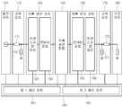
도 1에 도시된 바와 같이, 본 발명의 실시예에 따른 HVDC 시스템(100)은 발전 파트(101), 송전 측 교류 파트(110), 송전 측 변전 파트(103), 직류 송전 파트(140), 수요 측 변전 파트(105), 수요 측 교류 파트(170), 수요 파트(180), 및 제어 파트(190)를 포함한다. 송전 측 변전 파트(103)는 송전 측 트랜스포머 파트(120), 송전 측 교류-직류 컨버터 파트(130)를 포함한다. 수요 측 변전 파트(105)는 수요 측 직류-교류 컨버터 파트(150), 수요 측 트랜스포머 파트(160)를 포함한다.1, the HVDC system 100 according to the embodiment of the present invention includes a
발전 파트(101)는 3상의 교류 전력을 생성한다. 발전 파트(101)는 복수의 발전소를 포함할 수 있다.The
송전 측 교류 파트(110)는 발전 파트(101)가 생성한 3상 교류 전력을 송전 측 트랜스포머 파트(120)와 송전 측 교류-직류 컨버터 파트(130)를 포함하는 DC 변전소에 전달한다.The transmission
송전 측 트랜스포머 파트(120)는 송전 측 교류 파트(110)를 송전 측 교류-직류 컨버터 파트(130) 및 직류 송전 파트(140)로부터 격리한다(isolate).The transmission
송전 측 교류-직류 컨버터 파트(130)는 송전 측 트랜스포머 파트(120)의 출력에 해당하는 3상 교류 전력을 직류 전력으로 변환한다.The transmission AC-
직류 송전 파트(140)는 송전 측의 직류 전력을 수요 측으로 전달한다.The
수요 측 직류-교류 컨버터 파트(150)는 직류 송전 파트(140)에 의해 전달된 직류 전력을 3상 교류 전력으로 변환한다.The demand side DC-AC
수요 측 트랜스포머 파트(160)는 수요 측 교류 파트(170)를 수요 측 직류-교류 컨버터 파트(150)와 직류 송전 파트(140)로부터 격리한다.The demand side transformer part (160) isolates the demand side AC part (170) from the demand side DC - AC converter part (150) and the DC transmission part (140).
수요 측 교류 파트(170)는 수요 측 트랜스포머 파트(160)의 출력에 해당하는 3상 교류 전력을 수요 파트(180)에 제공한다.The demand
제어 파트(190)는 발전 파트(101), 송전 측 교류 파트(110), 송전 측 변전 파트(103), 직류 송전 파트(140), 수요 측 변전 파트(105), 수요 측 교류 파트(170), 수요 파트(180), 제어 파트(190), 송전 측 교류-직류 컨버터 파트(130), 수요 측 직류-교류 컨버터 파트(150) 중 적어도 하나를 제어한다. 특히, 제어 파트(190)는 송전 측 교류-직류 컨버터 파트(130)와 수요 측 직류-교류 컨버터 파트(150) 내의 복수의 밸브의 턴온 및 턴오프의 타이밍을 제어할 수 있다. 이때, 밸브는 싸이리스터 또는 절연 게이트 양극성 트랜지스터(insulated gate bipolar transistor, IGBT)에 해당할 수 있다.The
도 2는 본 발명의 실시예에 따른 모노폴라 방식의 고전압 직류 송전 시스템을 보여준다.2 shows a mono polar high voltage DC transmission system according to an embodiment of the present invention.
특히, 도 2는 단일의 극의 직류 전력을 송전하는 시스템을 보여준다. 이하의 설명에서는 단일의 극은 양극(positive pole)임을 가정하여 설명하나 이에 한정될 필요는 없다.In particular, Figure 2 shows a system for transmitting a single pole DC power. In the following description, it is assumed that a single pole is a positive pole, but the present invention is not limited thereto.
송전 측 교류 파트(110)는 교류 송전 라인(111)과 교류 필터(113)를 포함한다.The power transmission
교류 송전 라인(111)은 발전 파트(101)가 생성한 3상의 교류 전력을 송전 측 변전 파트(103)로 전달한다.The
교류 필터(113)는 변전 파트(103)에서 이용하는 주파수 성분 이외의 나머지 주파수 성분을 전달된 3상 교류 전력에서 제거한다.The
송전 측 트랜스포머 파트(120)는 양극을 위하여 하나 이상의 트랜스포머(121)를 포함한다. 양극을 위하여 송전 측 교류-직류 컨버터 파트(130)는 양극 직류 전력을 생성하는 교류-양극 직류 컨버터(131)를 포함하고, 이 교류-양극 직류 컨버터(131)는 하나 이상의 트랜스포머(121)에 각각 대응하는 하나 이상의 3상 밸브 브릿지(131a)를 포함한다.The transmission
하나의 3상 밸브 브릿지(131a)가 이용되는 경우, 교류-양극 직류 컨버터(131)는 교류 전력을 이용하여 6개의 펄스를 가지는 양극 직류 전력을 생성할 수 있다. 이때, 그 하나의 트랜스포머(121)의 1차측 코일과 2차측 코일은 Y-Y 형상의 결선을 가질 수도 있고, Y-델타(Δ) 형상의 결선을 가질 수도 있다.When one three-
2개의 3상 밸브 브릿지(131a)가 이용되는 경우, 교류-양극 직류 컨버터(131)는 교류 전력을 이용하여 12개의 펄스를 가지는 양극 직류 전력을 생성할 수 있다. 이때, 2개 중 하나의 트랜스포머(121)의 1차측 코일과 2차측 코일은 Y-Y 형상의 결선을 가질 수도 있고, 나머지 하나의 트랜스포머(121)의 1차측 코일과 2차측 코일은 Y-Δ 형상의 결선을 가질 수도 있다.When two three-
3개의 3상 밸브 브릿지(131a)가 이용되는 경우, 교류-양극 직류 컨버터(131)는 교류 전력을 이용하여 18개의 펄스를 가지는 양극 직류 전력을 생성할 수 있다. 양극 직류 전력의 펄스의 수가 많을수록, 필터의 가격이 낮아질 수 있다.When three three-
직류 송전 파트(140)는 송전 측 양극 직류 필터(141), 양극 직류 송전 라인(143), 수요 측 양극 직류 필터(145)를 포함한다.The
송전 측 양극 직류 필터(141)는 인덕터(L1)와 커패시터(C1)를 포함하며, 교류-양극 직류 컨버터(131)가 출력하는 양극 직류 전력을 직류 필터링한다.The transmission-side anode direct
양극 직류 송전 라인(143)는 양극 직류 전력의 전송을 위한 하나의 DC 라인을 가지고, 전류의 귀환 통로로는 대지가 이용될 수 있다. 이 DC 라인 상에는 하나 이상의 스위치가 배치될 수 있다.The bipolar
수요 측 양극 직류 필터(145)는 인덕터(L2)와 커패시터(C2)를 포함하며, 양극 직류 송전 라인(143)을 통해 전달된 양극 직류 전력을 직류 필터링한다.The demand side anode direct
수요 측 직류-교류 컨버터 파트(150)는 양극 직류-교류 컨버터(151)를 포함하고, 양극 직류-교류 컨버터(151)는 하나 이상의 3상 밸브 브릿지(151a)를 포함한다.The demand side dc-
수요 측 트랜스포머 파트(160)는 양극을 위하여 하나 이상의 3상 밸브 브릿지(151a)에 각각 대응하는 하나 이상의 트랜스포머(161)를 포함한다.The demand
하나의 3상 밸브 브릿지(151a)가 이용되는 경우, 양극 직류-교류 컨버터(151)는 양극 직류 전력을 이용하여 6개의 펄스를 가지는 교류 전력을 생성할 수 있다. 이때, 그 하나의 트랜스포머(161)의 1차측 코일과 2차측 코일은 Y-Y 형상의 결선을 가질 수도 있고, Y-델타(Δ) 형상의 결선을 가질 수도 있다.When one three-
2개의 3상 밸브 브릿지(151a)가 이용되는 경우, 양극 직류-교류 컨버터(151)는 양극 직류 전력을 이용하여 12개의 펄스를 가지는 교류 전력을 생성할 수 있다. 이때, 2개 중 하나의 트랜스포머(161)의 1차측 코일과 2차측 코일은 Y-Y 형상의 결선을 가질 수도 있고, 나머지 하나의 트랜스포머(161)의 1차측 코일과 2차측 코일은 Y-Δ 형상의 결선을 가질 수도 있다.When two three-
3개의 3상 밸브 브릿지(151a)가 이용되는 경우, 양극 직류-교류 컨버터(151)는 양극 직류 전력을 이용하여 18개의 펄스를 가지는 교류 전력을 생성할 수 있다. 교류 전력의 펄스의 수가 많을수록, 필터의 가격이 낮아질 수 있다.When three three-
수요 측 교류 파트(170)는 교류 필터(171)와 교류 송전 라인(173)을 포함한다.The demand
교류 필터(171)는 수요 파트(180)가 이용하는 주파수 성분(예컨데, 60Hz) 이외의 나머지 주파수 성분을, 수요 측 변전 파트(105)가 생성하는 교류 전력에서 제거한다.The
교류 송전 라인(173)은 필터링된 교류 전력을 수요 파트(180)에 전달한다.The
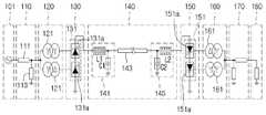
도 3은 본 발명의 실시예에 따른 바이폴라 방식의 고전압 직류 송전 시스템을 보여준다.3 shows a bipolar high voltage DC transmission system according to an embodiment of the present invention.
특히, 도 3은 2개의 극의 직류 전력을 송전하는 시스템을 보여준다. 이하의 설명에서는 2개의 극은 양극(positive pole)과 음극(negative pole)임을 가정하여 설명하나 이에 한정될 필요는 없다.In particular, Figure 3 shows a system for transmitting two pole DC power. In the following description, it is assumed that the two poles are a positive pole and a negative pole, but the present invention is not limited thereto.
송전 측 교류 파트(110)는 교류 송전 라인(111)과 교류 필터(113)를 포함한다.The power transmission
교류 송전 라인(111)은 발전 파트(101)가 생성한 3상의 교류 전력을 송전 측 변전 파트(103)로 전달한다.The
교류 필터(113)는 변전 파트(103)이 이용하는 주파수 성분 이외의 나머지 주파수 성분을 전달된 3상 교류 전력에서 제거한다.The
송전 측 트랜스포머 파트(120)는 양극을 위한 하나 이상의 트랜스포머(121)를 포함하고, 음극을 위한 하나 이상의 트랜스포머(122)를 포함한다. 송전 측 교류-직류 컨버터 파트(130)는 양극 직류 전력을 생성하는 교류-양극 직류 컨버터(131)와 음극 직류 전력을 생성하는 교류-음극 직류 컨버터(132)를 포함하고, 교류-양극 직류 컨버터(131)는 양극을 위한 하나 이상의 트랜스포머(121)에 각각 대응하는 하나 이상의 3상 밸브 브릿지(131a)를 포함하고, 교류-음극 직류 컨버터(132)는 음극을 위한 하나 이상의 트랜스포머(122)에 각각 대응하는 하나 이상의 3상 밸브 브릿지(132a)를 포함한다.The transmission
양극을 위하여 하나의 3상 밸브 브릿지(131a)가 이용되는 경우, 교류-양극 직류 컨버터(131)는 교류 전력을 이용하여 6개의 펄스를 가지는 양극 직류 전력을 생성할 수 있다. 이때, 그 하나의 트랜스포머(121)의 1차측 코일과 2차측 코일은 Y-Y 형상의 결선을 가질 수도 있고, Y-델타(Δ) 형상의 결선을 가질 수도 있다.When one three-
양극을 위하여 2개의 3상 밸브 브릿지(131a)가 이용되는 경우, 교류-양극 직류 컨버터(131)는 교류 전력을 이용하여 12개의 펄스를 가지는 양극 직류 전력을 생성할 수 있다. 이때, 2개 중 하나의 트랜스포머(121)의 1차측 코일과 2차측 코일은 Y-Y 형상의 결선을 가질 수도 있고, 나머지 하나의 트랜스포머(121)의 1차측 코일과 2차측 코일은 Y-Δ 형상의 결선을 가질 수도 있다.When two three-
양극을 위하여 3개의 3상 밸브 브릿지(131a)가 이용되는 경우, 교류-양극 직류 컨버터(131)는 교류 전력을 이용하여 18개의 펄스를 가지는 양극 직류 전력을 생성할 수 있다. 양극 직류 전력의 펄스의 수가 많을수록, 필터의 가격이 낮아질 수 있다.When three three-
음극을 위하여 하나의 3상 밸브 브릿지(132a)가 이용되는 경우, 교류-음극 직류 컨버터(132)는 6개의 펄스를 가지는 음극 직류 전력을 생성할 수 있다. 이때, 그 하나의 트랜스포머(122)의 1차측 코일과 2차측 코일은 Y-Y 형상의 결선을 가질 수도 있고, Y-델타(Δ) 형상의 결선을 가질 수도 있다.If one three-
음극을 위하여 2개의 3상 밸브 브릿지(132a)가 이용되는 경우, 교류-음극 직류 컨버터(132)는 12개의 펄스를 가지는 음극 직류 전력을 생성할 수 있다. 이때, 2개 중 하나의 트랜스포머(122)의 1차측 코일과 2차측 코일은 Y-Y 형상의 결선을 가질 수도 있고, 나머지 하나의 트랜스포머(122)의 1차측 코일과 2차측 코일은 Y-Δ 형상의 결선을 가질 수도 있다.When two three-
음극을 위하여 3개의 3상 밸브 브릿지(132a)가 이용되는 경우, 교류-음극 직류 컨버터(132)는 18개의 펄스를 가지는 음극 직류 전력을 생성할 수 있다. 음극 직류 전력의 펄스의 수가 많을수록, 필터의 가격이 낮아질 수 있다.When three three-
직류 송전 파트(140)는 송전 측 양극 직류 필터(141), 송전 측 음극 직류 필터(142), 양극 직류 송전 라인(143), 음극 직류 송전 라인(144), 수요 측 양극 직류 필터(145), 수요 측 음극 직류 필터(146)를 포함한다.The
송전 측 양극 직류 필터(141)는 인덕터(L1)와 커패시터(C1)를 포함하며, 교류-양극 직류 컨버터(131)가 출력하는 양극 직류 전력을 직류 필터링한다.The transmission-side anode direct
송전 측 음극 직류 필터(142)는 인덕터(L3)와 커패시터(C3)를 포함하며, 교류-음극 직류 컨버터(132)가 출력하는 음극 직류 전력을 직류 필터링한다.The power supply side cathode direct current filter 142 includes an inductor L3 and a capacitor C3 and DC-filters the cathode direct current power output from the AC-
양극 직류 송전 라인(143)는 양극 직류 전력의 전송을 위한 하나의 DC 라인을 가지고, 전류의 귀환 통로로는 대지가 이용할 수 있다. 이 DC 라인 상에는 하나 이상의 스위치가 배치될 수 있다.The bipolar
음극 직류 송전 라인(144)는 음극 직류 전력의 전송을 위한 하나의 DC 라인을 가지고, 전류의 귀환 통로로는 대지가 이용될 수 있다. 이 DC 라인 상에는 하나 이상의 스위치가 배치될 수 있다.The cathode
수요 측 양극 직류 필터(145)는 인덕터(L2)와 커패시터(C2)를 포함하며, 양극 직류 송전 라인(143)을 통해 전달된 양극 직류 전력을 직류 필터링한다.The demand side anode direct
수요 측 음극 직류 필터(146)는 인덕터(L4)와 커패시터(C4)를 포함하며, 음극 직류 송전 라인(144)을 통해 전달된 음극 직류 전력을 직류 필터링한다.The demand side cathode direct
수요 측 직류-교류 컨버터 파트(150)는 양극 직류-교류 컨버터(151)와 음극 직류-교류 컨버터(152)를 포함하고, 양극 직류-교류 컨버터(151)는 하나 이상의 3상 밸브 브릿지(151a)를 포함하고, 음극 직류-교류 컨버터(152)는 하나 이상의 3상 밸브 브릿지(152a)를 포함한다.
수요 측 트랜스포머 파트(160)는 양극을 위하여 하나 이상의 3상 밸브 브릿지(151a)에 각각 대응하는 하나 이상의 트랜스포머(161)를 포함하고, 음극을 위하여 하나 이상의 3상 밸브 브릿지(152a)에 각각 대응하는 하나 이상의 트랜스포머(162)를 포함한다.The demand
양극을 위하여 하나의 3상 밸브 브릿지(151a)가 이용되는 경우, 양극 직류-교류 컨버터(151)는 양극 직류 전력을 이용하여 6개의 펄스를 가지는 교류 전력을 생성할 수 있다. 이때, 그 하나의 트랜스포머(161)의 1차측 코일과 2차측 코일은 Y-Y 형상의 결선을 가질 수도 있고, Y-델타(Δ) 형상의 결선을 가질 수도 있다.When one three-
양극을 위하여 2개의 3상 밸브 브릿지(151a)가 이용되는 경우, 양극 직류-교류 컨버터(151)는 양극 직류 전력을 이용하여 12개의 펄스를 가지는 교류 전력을 생성할 수 있다. 이때, 2개 중 하나의 트랜스포머(161)의 1차측 코일과 2차측 코일은 Y-Y 형상의 결선을 가질 수도 있고, 나머지 하나의 트랜스포머(161)의 1차측 코일과 2차측 코일은 Y-Δ 형상의 결선을 가질 수도 있다.When two three-
양극을 위하여 3개의 3상 밸브 브릿지(151a)가 이용되는 경우, 양극 직류-교류 컨버터(151)는 양극 직류 전력을 이용하여 18개의 펄스를 가지는 교류 전력을 생성할 수 있다. 교류 전력의 펄스의 수가 많을수록, 필터의 가격이 낮아질 수 있다.When three three-
음극을 위하여 하나의 3상 밸브 브릿지(152a)가 이용되는 경우, 음극 직류-교류 컨버터(152)는 음극 직류 전력을 이용하여 6개의 펄스를 가지는 교류 전력을 생성할 수 있다. 이때, 그 하나의 트랜스포머(162)의 1차측 코일과 2차측 코일은 Y-Y 형상의 결선을 가질 수도 있고, Y-델타(Δ) 형상의 결선을 가질 수도 있다.When one three-
음극을 위하여 2개의 3상 밸브 브릿지(152a)가 이용되는 경우, 음극 직류-교류 컨버터(152)는 음극 직류 전력을 이용하여 12개의 펄스를 가지는 교류 전력을 생성할 수 있다. 이때, 2개 중 하나의 트랜스포머(162)의 1차측 코일과 2차측 코일은 Y-Y 형상의 결선을 가질 수도 있고, 나머지 하나의 트랜스포머(162)의 1차측 코일과 2차측 코일은 Y-Δ 형상의 결선을 가질 수도 있다.When two three-
음극을 위하여 3개의 3상 밸브 브릿지(152a)가 이용되는 경우, 음극 직류-교류 컨버터(152)는 음극 직류 전력을 이용하여 18개의 펄스를 가지는 교류 전력을 생성할 수 있다. 교류 전력의 펄스의 수가 많을수록, 필터의 가격이 낮아질 수 있다.When three three-
수요 측 교류 파트(170)는 교류 필터(171)와 교류 송전 라인(173)을 포함한다.The demand
교류 필터(171)는 수요 파트(180)가 이용하는 주파수 성분(예컨데, 60Hz) 이외의 나머지 주파수 성분을, 수요 측 변전 파트(105)가 생성하는 교류 전력에서 제거한다.The
교류 송전 라인(173)은 필터링된 교류 전력을 수요 파트(180)에 전달한다.The
도 4는 본 발명의 실시예에 따른 트랜스포머와 3상 밸브 브릿지의 결선을 보여준다.4 shows a connection of a transformer and a three-phase valve bridge according to an embodiment of the present invention.
특히, 도 4는 양극을 위한 2개의 트랜스포머(121)와 양극을 위한 2개의 3상 밸브 브릿지(131a)의 결선을 보여준다. 음극을 위한 2개의 트랜스포머(122)와 음극을 위한 2개의 3상 밸브 브릿지(132a)의 결선, 양극을 위한 2개의 트랜스포머(161)와 양극을 위한 2개의 3상 밸브 브릿지(151a)의 결선, 음극을 위한 2개의 트랜스포머(162)와 음극을 위한 2개의 3상 밸브 브릿지(152a)의 결선, 양극을 위한 1개의 트랜스포머(121)와 양극을 위한 1개의 3상 밸브 브릿지(131a), 양극을 위한 1개의 트랜스포머(161)와 양극을 위한 1개의 3상 밸브 브릿지(151a)의 결선 등은 도 4의 실시예로부터 용이하게 도출할 수 있으므로, 그 도면과 설명은 생략한다.Particularly, Fig. 4 shows the connection of two
도 4에서, Y-Y 형상의 결선을 가지는 트랜스포머(121)를 상측 트랜스포머, Y-Δ 형상의 결선을 가지는 트랜스포머(121)를 하측 트랜스포머, 상측 트랜스포머에 연결되는 3상 밸브 브릿지(131a)를 상측 3상 밸브 브릿지, 하측 트랜스포머에 연결되는 3상 밸브 브릿지(131a)를 하측 3상 밸브 브릿지라고 부르도록 한다.4, a
상측 3상 밸브 브릿지와 하측 3상 밸브 브릿지는 직류 전력을 출력하는 2개의 출력단인 제1 출력단(OUT1)과 제2 출력단(OUT2)을 가진다.The upper three-phase valve bridge and the lower three-phase valve bridge have a first output OUT1 and a second output OUT2, which are two output terminals for outputting DC power.
상측 3상 밸브 브릿지는 6개의 밸브(D1-D6)를 포함하고, 하측 3상 밸브 브릿지는 6개의 밸브(D7-D12)를 포함한다.The upper three-phase valve bridge includes six valves D1-D6, and the lower three-phase valve bridge includes six valves D7-D12.
밸브(D1)는 제1 출력단(OUT1)에 연결되는 캐소드와 상측 트랜스포머의 2차측 코일의 제1 단자에 연결되는 애노드를 가진다.The valve D1 has a cathode connected to the first output OUT1 and an anode connected to the first terminal of the secondary coil of the upper transformer.
밸브(D2)는 밸브(D5)의 애노드에 연결되는 캐소드와 밸브(D6)의 애노드에 연결되는 애노드를 가진다.The valve D2 has a cathode connected to the anode of the valve D5 and an anode connected to the anode of the valve D6.
밸브(D3)는 제1 출력단(OUT1)에 연결되는 캐소드와 상측 트랜스포머의 2차측 코일의 제2 단자에 연결되는 애노드를 가진다.The valve D3 has a cathode connected to the first output OUT1 and an anode connected to the second terminal of the secondary coil of the upper transformer.
밸브(D4)는 밸브(D1)의 애노드에 연결되는 캐소드와 밸브(D6)의 애노드에 연결되는 애노드를 가진다.The valve D4 has a cathode connected to the anode of the valve D1 and an anode connected to the anode of the valve D6.
밸브(D5)는 제1 출력단(OUT1)에 연결되는 캐소드와 상측 트랜스포머의 2차측 코일의 제3 단자에 연결되는 애노드를 가진다.The valve D5 has a cathode connected to the first output OUT1 and an anode connected to the third terminal of the secondary coil of the upper transformer.
밸브(D6)는 밸브(D3)의 애노드에 연결되는 캐소드를 가진다.The valve D6 has a cathode connected to the anode of the valve D3.
밸브(D7)는 밸브(D6)의 애노드에 연결되는 캐소드와 하측 트랜스포머의 2차측 코일의 제1 단자에 연결되는 애노드를 가진다.The valve D7 has a cathode connected to the anode of the valve D6 and an anode connected to the first terminal of the secondary coil of the lower transformer.
밸브(D8)는 밸브(D11)의 애노드에 연결되는 캐소드와 제2 출력단(OUT2)에 연결되는 애노드를 가진다.The valve D8 has a cathode connected to the anode of the valve D11 and an anode connected to the second output OUT2.
밸브(D9)는 밸브(D6)의 애노드에 연결되는 캐소드와 하측 트랜스포머의 2차측 코일의 제2 단자에 연결되는 애노드를 가진다.The valve D9 has a cathode connected to the anode of the valve D6 and an anode connected to the second terminal of the secondary coil of the lower transformer.
밸브(D10)는 밸브(D7)의 애노드에 연결되는 캐소드와 제2 출력단(OUT2)에 연결되는 애노드를 가진다.The valve D10 has a cathode connected to the anode of the valve D7 and an anode connected to the second output OUT2.
밸브(D11)는 밸브(D6)의 애노드에 연결되는 캐소드와 하측 트랜스포머의 2차측 코일의 제3 단자에 연결되는 애노드를 가진다.The valve D11 has a cathode connected to the anode of the valve D6 and an anode connected to the third terminal of the secondary coil of the lower transformer.
밸브(D12)는 밸브(D9)의 애노드에 연결되는 캐소드와 제2 출력단(OUT2)에 연결되는 애노드를 가진다.The valve D12 has a cathode connected to the anode of the valve D9 and an anode connected to the second output OUT2.
도 5는 본 발명의 일 실시 예에 따른 데이터 처리 장치의 구성을 설명하기 위한 도면이다.5 is a diagram for explaining a configuration of a data processing apparatus according to an embodiment of the present invention.
도 5를 참조하면, 데이터 처리 장치(200)는 복수의 전처리 그룹들(10a…10n) 및 복수의 제어부들(5a…5n)을 포함한다.Referring to FIG. 5, the
데이터 처리 장치(200)는 도 1에서 설명한 고전압 직류 송전 시스템의 제어 파트(190)에 포함될 수 있다.The
복수의 전처리 그룹들(10a…10n) 각각은 복수의 전처리부들(1a…1n)을 포함할 수 있다. 복수의 전처리 그룹들(10a…10n) 각각은 복수의 제어부들(5a…5n) 각각에 대응될 수 있다.Each of the plurality of preprocessing groups 10a to 10n may include a plurality of
제1 전처리 그룹(10a)에 포함된 복수의 전처리부들(1a…1n) 각각의 출력단자는 광도파관(4)을 통해 다음의 전처리부의 입력단자에 연결될 수 있다. 복수의 전처리부들(1a…1n) 각각은 출력단자(2)를 통해 다음의 전처리부의 입력단자에 데이터를 전송할 수 있다.The output terminals of each of the plurality of
마지막에 배치된 전처리부(1n)는 광도파관(4)을 통해 제어부(5a)에 연결될 수 있다.The
복수의 전처리부들(1a…1n)은 다양한 측정부들(미도시)과 연결될 수 있다.The plurality of
복수의 전처리부들(1a…1n) 각각은 측정부에서 측정된 측정 값들이 전처리하고, 변환하여 복수의 제어부들(5a…5n) 각각에 전달할 수 있다.Each of the plurality of
제1 전처리부(1a)는 측정부로부터 전달받은 측정 값을 전처리하여 제1 전처리 데이터를 출력한다.The
제1 전처리부(1a)의 출력단자(2)에서 출력된 제1 전처리 데이터는 광 도파관(4)을 통해 제2 전처리부(1b)의 입력단자(3)로 전달된다. 제2 전처리부(1b)의 입력단자(3)를 통해 전달된 제1 전처리 데이터는 제2 전처리부(1b)의 제2 전처리 데이터와 함께 다음의 전처리부의 입력단자로 전달된다. 마지막에 배치된 제n 전처리부(1n)로부터 전달된 전처리 데이터는 제어부(5)로 전달된다.The first preprocessed data output from the
복수의 제어부들(5a…5n) 각각은 복수의 전처리 그룹들 각각으로부터 전처리 데이터를 수신한다.Each of the plurality of control units 5a ... 5n receives the preprocessing data from each of the plurality of preprocessing groups.
복수의 제어부들(5a…5n) 각각은 수신한 전처리 데이터를 코딩하여 외부로 전송할 수 있다.Each of the plurality of control units 5a ... 5n may code the received pre-processing data and transmit it to the outside.
도 6은 본 발명의 일 실시 예에 따라 각 전처리부로부터 데이터가 전송되는 타이밍을 설명하기 위한 도면이다.FIG. 6 is a view for explaining the timing at which data is transmitted from each preprocessing unit according to an embodiment of the present invention; FIG.
도 6을 참조하면, 데이터 워드(data word, 6)는 시작 비트(8)가 부착된 동기 신호(7)에서 시작한다. 복수의 비트 그룹들(9…14n) 및 체크 비트 그룹(15)은 시작 비트(8)의 다음에 배치될 수 있다.Referring to FIG. 6, a
제1 비트 그룹(9)은 2개의 비트 그룹 엘리먼트들(10, 11)을 포함할 수 있다. 2개의 비트 그룹 엘리먼트들(10, 11) 각각은 8bit 의 길이를 갖는다.The
제1 비트 그룹 엘리먼트(10)는 각 전처리부를 식별하는 비트 시퀀스를 포함한다. 제2 비트 그룹 엘리먼트(11)는 제1 비트 그룹(9)을 뒤따르는 복수의 비트 그룹들(12, 13, 14a…14n, 15)에 대한 정보를 포함한다. 복수의 비트 그룹들(12, 13, 14a…14n, 15)은 복수의 측정 값들, 상태 및 체크 비트 그룹에 대응한다.The first
제2 비트 그룹(12) 및 제3 비트 그룹(13)은 측정부로부터 측정된 측정값들의 상태 정보를 포함한다. 측정값들의 상태에 대한 정보는 전처리부에서 생성된 측정값들의 상태에 대한 정보일 수 있다. 측정값들의 상태 정보는 측정 값들의 유효성에 대한 정보 및 전처리 과정이 수행되었는지에 대한 정보를 포함할 수 있다.The
제3 비트 그룹(13)을 뒤따르는 복수의 비트 그룹들(14a…14n) 각각은 전처리부에서 생성된 복수의 측정 값들 각각에 대응한다.Each of the plurality of
복수의 비트 그룹들(14a…14n)을 뒤따르는 체크 비트 그룹(15)은 데이터 워드(6)를 사용하여 전송될 데이터가 신뢰할 수 있는 데이터인지를 체크하는데 사용될 수 있다.A
도 7은 본 발명의 일 실시 예에 따라 각 전처리부로부터 데이터 워드를 갖는 데이터 레코드들을 보여주는 도면이다.7 is a view showing data records having data words from respective preprocessing units according to an embodiment of the present invention.
도 7을 참조하면, 복수의 데이터 워드들(6a…6n) 각각은 도 6에서 설명한 데이터 워드(6)에 대응한다.Referring to FIG. 7, each of the plurality of
제1 데이터 레코드(16)는 도 5에서 설명한 제1 전처리부(1a)에서 출력된 제1데이터 워드(6a)를 포함한다.The
제2 데이터 레코드(17)는 제1 데이터 워드(6a) 및 도 5에서 설명한 제2 전처리부(1b)에서 출력된 제2 데이터 워드(6b)를 포함한다.The
제n 데이터 레코드(18)는 복수의 전처리부들(1a…1n)에서 출력된 데이터 워드들(6a…6n)을 포함한다.The n-
제1 전처리부(1a)는 마스터로 사용될 수 있고, 마스터 동기 신호(19)를 이용하여 데이터 전송을 시작할 수 있다.The
제1 전처리부(1a)는 마스터 동기 신호(19)를 생성한 후, 도 6에 도시된 바와 같은 포맷의 제1 데이터 워드(6a)를 전송한다. 도 6에서 설명한 바와 같이, 제1 데이터 워드(6a)는 제1 비트 그룹(9)을 뒤따르는 복수의 비트 그룹들(12, 13, 14a…14n, 15)의 개수에 대한 정보를 포함하는 제2 비트 그룹 엘리먼트(11)를 포함한다.After generating the
복수의 비트 그룹들(12, 13, 14a…14n, 15)의 개수에 대한 정보는 제2 전처리부(1b)가 자신의 동기 신호(7b) 및 제2 데이터 워드(6b)를 어느 타이밍에 제1 데이터 워드(6a)의 다음에 삽입하는지를 나타내는 삽입 시간을 결정하는데 사용될 수 있다. 삽입 시간에 결정됨에 따라 제2 데이터 레코드(17)가 생성될 수 있다.Information on the number of the plurality of
이러한 방법으로 다음의 전처리부들 각각은 자신의 동기 신호 및 데이터 워드를 삽입하여 데이터 레코드를 생성할 수 있다. 최종적으로 제n 데이터 레코드(18)가 생성될 수 있다.In this way, each of the following preprocessing units can generate a data record by inserting its own synchronization signal and data word. Finally, the n-
제n 전처리부(1n)에서 출력된 데이터는 광 도파선(4)을 통해 제어부(5)로 전달될 수 있다. 제어부(5)는 제n 전처리부(1n)에서 출력된 데이터에 추가적인 처리 과정을 수행할 수 있다.The data output from the n-
도 8은 본 발명의 일 실시 예에 따라 측정 데이터를 코딩하는 과정을 설명하는 도면이다.8 is a view for explaining a process of coding measurement data according to an embodiment of the present invention.
도 5에서 설명한 복수의 제어부들 각각은 2위상 코딩(bi-phase) 방식을 이용하여 각 전처리부의 측정 값들 각각을 코딩할 수 있다.Each of the plurality of control units described in FIG. 5 can code each measurement value of each preprocessing unit using a bi-phase coding scheme.
2위상 코딩 방식을 사용하는 경우, 측정 값은 로우 신호를 나타내는 0 및 하이 신호를 나타내는 1에 의해 표현될 수 있다. 2위상 코딩 방식은 하나의 데이터 워드안에서 연속적인 로우 상태 또는 하이 상태를 허용하지 않는다.If a two-phase coding scheme is used, the measured value can be represented by 0 representing a low signal and 1 representing a high signal. The two-phase coding scheme does not allow continuous low or high states within a single data word.
도 8을 참조하면, 측정 값을 나타내는 측정 데이터(20)는 로우 신호들 및 하이 신호들을 포함한다. 제어부는 2위상 코딩 방식을 통해 측정 데이터(20)를 코딩하고, 코딩된 전송 신호(21)를 생성할 수 있다. 코딩된 전송 신호(21)는 연속적인 로우 신호 및 연속적인 하이 신호를 갖지 않는다. 이러한 코딩 방식은 동기 신호가 전송 신호(21)상에 명확히 나타나도록 한다. 일 실시 예에서 제1 전처리부(1a)에서 생성된 마스터 동기 신호(19)는 13개의 로우 신호가 연속적으로 나타나도록 표현될 수 있고, 제1 전처리부(1a)를 제외한 나머지 전처리부들부터 생성된 동기 신호들(7b…7n) 각각은 7개의 로우 신호가 연속적으로 나타나도록 표현될 수 있다.Referring to FIG. 8, the
다음으로 도 9 내지 도 12를 설명한다.Next, Figs. 9 to 12 will be described.
도 9 내지 도 12에서 각 구성요소간의 데이터 전송은 파장 분할 다중화(WDM: Wavelength Division Mutiplexing)방식을 기반으로 수행될 수 있다. 파장 분할 다중화는 복수의 파장들을 하나의 광섬유를 통해 통신하는 방식이다.In FIGS. 9 to 12, data transmission between the respective components can be performed based on a WDM (Wavelength Division Multiplexing) scheme. Wavelength division multiplexing is a method of communicating a plurality of wavelengths through one optical fiber.
도 9 및 도 10은 본 발명의 또 다른 실시 예에 따른 고전압 직류 송전 시스템의 데이터 처리 장치를 설명하기 위한 도면이다.9 and 10 are views for explaining a data processing apparatus of a high-voltage DC transmission system according to another embodiment of the present invention.
도 9는 본 발명의 또 다른 실시 예에 따른 데이터 처리 장치의 블록도이고, 도 10은 본 발명의 또 다른 실시 예에 따른 데이터 처리 장치의 실제 구성을 보여준다.FIG. 9 is a block diagram of a data processing apparatus according to another embodiment of the present invention, and FIG. 10 shows an actual configuration of a data processing apparatus according to another embodiment of the present invention.
데이터 처리 장치(300)는 도 1에 도시된 제어 파트(190)에 포함될 수 있으나, 이에 한정될 필요는 없고, 별도의 수단으로 구성될 수 있다.The
도 9를 참조하면, 데이터 처리 장치(300)는 측정모듈(310), 데이터 생성부(320), 인터페이스부(330), 데이터 수집부(340) 및 제어부(350)를 포함한다.Referring to FIG. 9, the
측정모듈(310)은 고전압 직류 송전 시스템의 하나 이상의 지점에 대한 측정 값들을 획득한다. 일 실시 예에서 측정모듈(310)은 도 1 내지 도 2에서 도시된 고전압 직류 송전 시스템의 어느 한 지점에 대한 측정 값들을 획득할 수 있다. 측정 값들은 교류 파트(110, 170)의 일 지점에 대한 교류전압 및 교류 파트(110, 170)의 일 지점에 대한 교류전류를 포함할 수 있다. 또한, 측정 값들은 직류 송전 파트(140)의 직류전압 및 직류 송전 파트(140)의 일 지점에 대한 직류전류을 포함할 수 있다. 그러나, 이에 한정될 필요는 없고, 측정 값들은 고전압 직류 송전 시스템을 구성하는 구성요소의 입력단자의 전압/전류 또는 출력단자의 전압/전류를 포함할 수 있다.The
데이터 생성부(320)는 측정모듈(310)로부터 획득한 측정 값들을 이용하여 측정 데이터 유닛을 생성한다. 데이터 생성부(320)는 복수의 데이터 유닛 생성부들(320a…320n)을 포함할 수 있고, 복수의 데이터 유닛 생성부들(320a…320n) 각각은 측정모듈(310)로부터 획득한 측정 값들을 이용하여 측정 데이터 유닛을 생성할 수 있다. 복수의 데이터 유닛 생성부들(320a…320n) 각각은 측정모듈(310)로부터 전달받은 측정 값들을 전처리(preprocessing)할 수 있다. 복수의 데이터 유닛 생성부들(320a…320n) 각각은 측정 값들을 제어부(350)가 측정 값들에 대한 유효 값을 추출하도록 불필요한 정보를 제거하는 예비적인 처리 과정을 수행할 수 있다. 복수의 데이터 유닛 생성부들(320a…320n) 각각은 전처리 과정을 수행하여 측정 데이터 유닛을 생성할 수 있다.The
복수의 데이터 유닛 생성부들(320a…320n) 각각은 인터페이스부(330)를 통해 전처리된 측정 데이터 유닛을 데이터 수집부(340)에 전달할 수 있다.Each of the plurality of
인터페이스부(330)는 복수의 데이터 유닛 생성부들(320a…320n) 각각으로부터 생성된 복수의 측정 데이터 유닛들을 데이터 수집부(340)에 전달한다.The
인터페이스부(330)는 복수의 데이터 유닛 생성부들(320a…320n) 각각으로부터 생성된 복수의 측정 데이터 유닛들을 데이터 수집부(340)에 병렬적으로 전달한다.The
인터페이스부(330)는 복수의 데이터 유닛 생성부(320a…320n)들 각각으로부터 생성된 측정 데이터 유닛을 백플레인 버스(backplane BUS) 규격을 이용하여 데이터 수집부(340)로 전달할 수 있다. 인터페이스부(330)는 복수의 데이터 유닛 생성부들(320a…320n) 및 데이터 수집부(340)를 서로 연결하여 측정 데이터 유닛의 전달을 위한 통로 역할을 수행할 수 있다.The
데이터 수집부(340)는 인터페이스부(330)를 통해 전달된 복수의 측정 데이터 유닛들을 수집한다.The
일 실시 예에서 데이터 수집부(340)는 인터페이스부(330)를 통해 전달된 복수의 측정 데이터 유닛들을 동시에 수집할 수 있다. 즉, 데이터 수집부(340)는 백플레인 버스(backplane BUS) 규격을 통해 복수의 측정 데이터 유닛들을 동시에 수집할 수 있다.In one embodiment, the
데이터 수집부(340)는 버퍼(buffer) 역할을 수행할 수 있다. 즉, 데이터 수집부(340)는 복수의 데이터 유닛 생성부들(320a…320n)과 제어부(350) 간에 데이터를 송수신할 때 데이터를 임시로 기억하는 임시 기억장소로 활용될 수 있다.The
데이터 수집부(340)는 게이트 모듈이라 명명될 수 있다.The
데이터 수집부(340)는 수집된 복수의 측정 데이터 유닛들에 기초하여 측정 데이터 패킷을 생성한다.The
일 실시 예에서 데이터 수집부(340)는 복수의 측정 데이터 유닛들을 이용하여 하나의 측정 데이터 패킷을 생성할 수 있다.In one embodiment, the
데이터 수집부(340)는 생성된 측정 데이터 패킷을 코딩하여 코딩된 측정 데이터 패킷을 생성할 수 있다. 데이터 수집부(340)는 복수의 측정 데이터 유닛들 각각을 코딩하여 코딩된 결과를 이용하여 하나의 측정 데이터 패킷을 생성할 수 있다.The
데이터 수집부(340)는 생성된 데이터 패킷을 제어부(350)에 전송한다.The
제어부(350)는 트리거에 기초하여 수신된 측정 데이터 패킷을 외부에 제공한다.The
트리거는 측정 데이터 패킷의 전송을 개시하는 동기일 수 있다.The trigger may be a synchronization to initiate transmission of the measurement data packet.
일 실시 예에서 트리거는 일정 주기의 시간 마다 생성될 수 있다. 즉, 제어부(350)는 정해진 시간 간격 마다 측정 데이터 패킷을 외부에 제공할 수 있다.In one embodiment, the trigger may be generated every time a certain period of time. That is, the
또 다른 실시 예에서 트리거는 불규칙적인 시간 마다 생성될 수 있다. 제어부(350)는 불규칙적인 시간 간격 마다 측정 데이터 패킷을 외부에 제공할 수 있다.In yet another embodiment, a trigger may be generated at irregular times. The
또 다른 실시 예에서 트리거는 다른 제어부의 요청일 수 있다. 즉, 예를 들어, 도 10에 도시된 제1 제어부(350_1)는 제2 제어부(350_2)의 요청에 의해 측정 데이터 패킷을 제2 제어부(350_2)에 제공할 수 있다. 마찬가지로, 제2 제어부(350_2)는 제1 제어부(350_1)의 요청에 의해 측정 데이터 패킷을 제1 제어부(350_1)에 제공할 수 있다.In yet another embodiment, the trigger may be a request from another control. That is, for example, the first controller 350_1 shown in FIG. 10 can provide the second controller 350_2 with a measurement data packet at the request of the second controller 350_2. Similarly, the second control unit 350_2 may provide the measurement data packet to the first control unit 350_1 at the request of the first control unit 350_1.
제1 제어부(350_1)는 제2 제어부(350_2)는 광케이블을 이용하여 측정 데이터 패킷을 송수신할 수 있다.The first control unit 350_1 can transmit and receive the measurement data packet using the optical cable by the second control unit 350_2.
또 다른 실시 예에서 트리거는 사용자의 요청일 수 있다. 제어부(350)는 사용자의 요청에 따라 측정 데이터 패킷을 사용자의 단말기에 제공할 수 있다. 여기서, 사용자의 단말기는 컴퓨터, 노트북, 스마트 폰 등과 같은 이동 단말기일 수 있으나, 이에 한정될 필요는 없다.In yet another embodiment, the trigger may be a user request. The
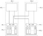
도 10을 참조하면, 제1 데이터 처리 장치(300_1) 및 제2 데이터 처리 장치(300_2)가 도시되어 있다. 제1 데이터 처리 장치(300_1) 및 제2 데이터 처리 장치(300_2) 각각의 구성은 도 9에서 설명한 것과 같다. 다만, 일부 구성요소는 생략했다.Referring to FIG. 10, a first data processing apparatus 300_1 and a second data processing apparatus 300_2 are shown. The configurations of the first data processing apparatus 300_1 and the second data processing apparatus 300_2 are the same as those described in FIG. However, some components are omitted.
제1 제어부(350_1)는 제1 데이터 처리 장치(300_1)의 측정 데이터 패킷을 제2 데이터 수집부(340_2)를 통해 제2 제어부(350_2)로 전달할 수 있다.The first controller 350_1 may transmit the measurement data packet of the first data processor 300_1 to the second controller 350_2 through the second data collector 340_2.
제2 제어부(350_2)는 제2 데이터 처리 장치(300_2)의 측정 데이터 패킷을 제1 데이터 수집부(340_1)를 통해 제1 제어부(350_1)로 전달할 수 있다.The second control unit 350_2 may transmit the measurement data packet of the second data processing unit 300_2 to the first control unit 350_1 through the first data collection unit 340_1.
다음으로 도 11을 설명한다.Next, Fig. 11 will be described.
도 11은 본 발명의 일 실시 예에 따른 데이터 처리 장치의 동작 방법을 설명하기 위한 흐름도이다.11 is a flowchart illustrating an operation method of a data processing apparatus according to an embodiment of the present invention.
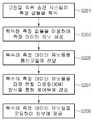
도 11을 참조하면, 데이터 처리 장치(300)의 측정모듈(310)은 고전압 직류 송전 시스템의 하나 이상의 지점에 대한 측정 값들을 획득한다(S101).Referring to FIG. 11, the
일 실시 예에서 측정모듈(310)은 도 1 내지 도 2에서 도시된 고전압 직류 송전 시스템의 어느 한 지점에 대한 측정 값들을 획득할 수 있다. 측정 값들은 교류 파트(110, 170)의 일 지점에 대한 교류전압 및 교류 파트(110, 170)의 일 지점에 대한 교류전류를 포함할 수 있다. 또한, 측정 값들은 직류 송전 파트(140)의 직류전압 및 직류 송전 파트(140)의 일 지점에 대한 직류전류를 포함할 수 있다. 그러나, 이에 한정될 필요는 없고, 측정 값들은 고전압 직류 송전 시스템을 구성하는 구성요소의 입력단자의 전압/전류 또는 출력단자의 전압/전류를 포함할 수 있다.In one embodiment, the
측정모듈(310)은 복수의 측정부들(미도시)를 포함할 수 있다. 복수의 측정부들 각각은 측정 값들을 복수의 데이터 유닛 생성부들(320a…320n)에 전달할 수 있다.The
복수의 데이터 유닛 생성부들(320a…320n) 각각은 측정모듈(310)로부터 획득한 측정 값들을 이용하여 측정 데이터 유닛을 생성한다(S103).Each of the plurality of
복수의 데이터 유닛 생성부들(320a…320n) 각각은 측정모듈(310)로부터 전달받은 측정 값들을 전처리(preprocessing)할 수 있다. 복수의 데이터 유닛 생성부들(320a…320n) 각각은 측정 값들을 제어부(350)가 측정 값들에 대한 유효 값을 추출하도록 불필요한 정보를 제거하는 예비적인 처리 과정을 수행할 수 있다. 복수의 데이터 유닛 생성부들(320a…320n) 각각은 전처리 과정을 수행하여 측정 데이터 유닛을 생성할 수 있다.Each of the plurality of
복수의 데이터 유닛 생성부들(320a…320n) 각각은 인터페이스부(330)를 통해 전처리된 측정 데이터 유닛을 데이터 수집부(340)에 전달할 수 있다.Each of the plurality of
인터페이스부(330)는 복수의 데이터 유닛 생성부들(320a…320n) 각각으로부터 생성된 복수의 측정 데이터 유닛들을 데이터 수집부(340)에 전달한다(S105).The
인터페이스부(330)는 복수의 데이터 유닛 생성부(320a…320n)들 각각으로부터 생성된 측정 데이터 유닛을 백플레인 버스(backplane BUS) 규격을 이용하여 데이터 수집부(340)로 전달할 수 있다. 인터페이스부(330)는 복수의 데이터 유닛 생성부들(320a…320n) 및 데이터 수집부(340)를 서로 연결하여 측정 데이터 유닛의 전달을 위한 통로 역할을 수행할 수 있다.The
인터페이스부(330)는 복수의 측정 데이터 유닛들을 하나의 광케이블을 통해 상기 데이터 수집부(340)에 전달할 수 있다. 즉, 복수의 데이터 유닛 생성부들(320a…320n)은 하나의 광케이블을 공유할 수 있다.The
이에 따라, 인터페이스부(330)는 복수의 측정 데이터 유닛들을 1개의 케이블을 통해 병렬적으로 전송할 수 있다. 이 경우, 인터페이스부(330)는 파장 분할 다중화 방식을 이용하여 복수의 측정 데이터 유닛들을 데이터 수집부(340)에 전달할 수 있다.Accordingly, the
데이터 수집부(340)는 인터페이스부(330)를 통해 전달된 복수의 측정 데이터 유닛들을 수집한다(S107).The
일 실시 예에서 데이터 수집부(340)는 인터페이스부(330)를 통해 전달된 복수의 측정 데이터 유닛들을 동시에 수집할 수 있다. 즉, 데이터 수집부(340)는 백플레인 버스(backplane BUS) 규격을 통해 복수의 측정 데이터 유닛들을 동시에 수집할 수 있다.In one embodiment, the
데이터 수집부(340)는 버퍼(buffer) 역할을 수행할 수 있다. 즉, 데이터 수집부(340)는 복수의 데이터 유닛 생성부들(320a…320n)과 제어부(350) 간에 데이터를 송수신할 때 데이터를 임시로 기억하는 임시 기억장소로 활용될 수 있다.The
데이터 수집부(340)는 게이트 모듈이라 명명될 수 있다.The
데이터 수집부(340)는 수집된 복수의 측정 데이터 유닛들에 기초하여 측정 데이터 패킷을 생성한다(S109).The
일 실시 예에서 데이터 수집부(340)는 복수의 측정 데이터 유닛들을 이용하여 하나의 측정 데이터 패킷을 생성할 수 있다.In one embodiment, the
데이터 수집부(340)는 생성된 측정 데이터 패킷을 코딩하여 코딩된 측정 데이터 패킷을 생성할 수 있다. 데이터 수집부(340)는 복수의 측정 데이터 유닛들 각각을 코딩하여 코딩된 결과를 이용하여 하나의 측정 데이터 패킷을 생성할 수 있다.The
측정 데이터 패킷의 구조에 대해서는 도 12를 참조하여 설명한다.The structure of the measurement data packet will be described with reference to FIG.
도 12는 본 발명의 일 실시 예에 따른 측정 데이터 패킷의 구조를 설명하기 위한 도면이다.12 is a diagram for explaining a structure of a measurement data packet according to an embodiment of the present invention.
도 12를 참조하면, 측정 데이터 패킷은 헤더(321), 측정 데이터(323) 및 체크 코드(325)를 포함할 수 있다.Referring to FIG. 12, the measurement data packet may include a
헤더(321)는 식별자 필드 및 길이 필드를 포함한다.The
식별자(ID) 필드는 측정 데이터 패킷을 식별하는 필드이다.The identifier (ID) field is a field for identifying a measurement data packet.
길이(length) 필드는 헤더(321)를 뒤따르는 측정 데이터(323) 및 체크 코드(325)의 길이를 나타내는 필드이다.The length field is a field indicating the length of the
헤더(321)는 각 측정 데이터 유닛의 헤더를 포함하지 않을 수 있다. 각 측정 데이터 유닛은 헤더를 포함하지 않을 수 있다. 이에 따라 측정 데이터 패킷의 헤더는 단순히 측정 데이터 패킷을 나타내는 정보만을 포함할 수 있다.The
헤더(321) 다음에는 측정 데이터(323) 및 체크 코드(325)가 뒤따른다.
측정 데이터(323)는 데이터 유닛 생성부에서 전처리된 복수의 측정 값들에 대한 정보를 포함한다. 측정 데이터(323)는 복수의 측정 데이터 필드(measurement data field 1…n)들을 포함한다. 복수의 측정 데이터 필드들 각각은 복수의 데이터 유닛 생성부들 각각에 대응한다. 즉, 복수의 측정 데이터 필드들 각각은 복수의 데이터 유닛 생성부들로부터 전달받은 복수의 측정 값들을 나타낼 수 있다.The
측정 데이터(323) 다음에는 체크 코드(325)가 뒤따른다.The
체크 코드(325)는 측정 데이터 패킷이 신뢰할 수 있는 데이터 유닛인지 체크하는데 사용된다. 즉, 체크 코드(325)는 측정 데이터 패킷의 에러를 체크하는데 사용될 수 있다. 체크 코드(325)는 순환 중복 검사(Cyclic Redundancy Check, CRC)일 수 있으나, 이는 예시에 불과하다.The
도 12와 같은 측정 데이터 패킷의 경우, 도 6에 도시된 실시 예에 비해 헤더의 수를 감소시킬 수 있다. 즉, 도 6의 실시 예에 따른 복수의 데이터 레코드들은 각 전처리부에 대한 복수의 헤더를 포함한다. 그러나, 도 12의 실시 예에 따른 측정 데이터 패킷은 하나의 헤더만을 포함하므로, 도 12의 실시 예는 상대적으로 오버 헤드를 줄일 수 있다.In the case of the measurement data packet as shown in FIG. 12, the number of headers can be reduced as compared with the embodiment shown in FIG. That is, the plurality of data records according to the embodiment of FIG. 6 includes a plurality of headers for each preprocessing unit. However, since the measurement data packet according to the embodiment of FIG. 12 includes only one header, the embodiment of FIG. 12 can reduce relative overhead.
또한, 본 발명의 실시 예에 따르면, 복수의 데이터 유닛 생성부에서 전송되는 측정 데이터 유닛은 시분할되어 전송되지 않으므로, 전송 동기에 민감하지 않는 효과가 있다.Further, according to the embodiment of the present invention, since the measurement data units transmitted from the plurality of data unit generators are not transmitted in time division, they are not sensitive to the transmission motions.
또한, 또한, 본 발명의 실시 예에 따르면, 복수의 데이터 유닛 생성부에서 전송되는 측정 데이터 유닛은 하나의 인터페이스를 통해 전송되므로, 케이블 배선수를 줄일 수 있고, 시스템의 구조를 단순하게 한다.In addition, according to the embodiment of the present invention, since the measurement data units transmitted from the plurality of data unit generation units are transmitted through one interface, it is possible to reduce the cable diversity and simplify the structure of the system.
다시 도 11을 설명한다.11 will be described again.
데이터 수집부(340)는 생성된 측정 데이터 패킷을 제어부(350)에 전송한다(S111).The
일 실시 예에서 데이터 수집부(340)는 파장 분할 다중화(WDM: Wavelength Division Mutiplexing)를 이용하여 측정 데이터 패킷을 제어부(350)에 전송할 수 있다. 파장 분할 다중화는 복수의 파장들을 하나의 광섬유를 통해 통신하는 방식이다.In one embodiment, the
제어부(350)는 트리거에 기초하여 수신된 측정 데이터 패킷을 외부에 제공한다(S113).The
트리거는 측정 데이터 패킷의 전송을 개시하는 동기일 수 있다.The trigger may be a synchronization to initiate transmission of the measurement data packet.
일 실시 예에서 트리거는 데이터 처리 장치(300)에 기 설정된 시간적 동기일 수 있다. 트리거는 일정 주기의 시간 마다 생성될 수 있다. 즉, 제어부(350)는 정해진 시간 간격 마다 측정 데이터 패킷을 외부에 제공할 수 있다.In one embodiment, the trigger may be a predetermined temporal synchronization to the
또한, 트리거는 불규칙적인 시간 마다 생성될 수 있다. 제어부(350)는 불규칙적인 시간 간격 마다 측정 데이터 패킷을 외부에 제공할 수 있다.In addition, triggers can be generated at irregular intervals. The
또 다른 실시 예에서 트리거는 다른 제어부의 요청일 수 있다. 즉, 예를 들어, 도 10에 도시된 제1 제어부(350_1)는 제2 제어부(350_2)의 요청에 의해 측정 데이터 패킷을 제2 제어부(350_2)에 제공할 수 있다. 마찬가지로, 제2 제어부(350_2)는 제1 제어부(350_1)의 요청에 의해 측정 데이터 패킷을 제1 제어부(350_1)에 제공할 수 있다.In yet another embodiment, the trigger may be a request from another control. That is, for example, the first controller 350_1 shown in FIG. 10 can provide the second controller 350_2 with a measurement data packet at the request of the second controller 350_2. Similarly, the second control unit 350_2 may provide the measurement data packet to the first control unit 350_1 at the request of the first control unit 350_1.
제1 제어부(350_1)는 제2 제어부(350_2)는 광케이블을 이용하여 측정 데이터 패킷을 송수신할 수 있다.The first control unit 350_1 can transmit and receive the measurement data packet using the optical cable by the second control unit 350_2.
또 다른 실시 예에서 트리거는 사용자의 요청일 수 있다. 제어부(350)는 사용자의 요청에 따라 측정 데이터 패킷을 사용자의 단말기에 제공할 수 있다. 여기서, 사용자의 단말기는 컴퓨터, 노트북, 스마트 폰 등과 같은 이동 단말기일 수 있으나, 이에 한정될 필요는 없다.In yet another embodiment, the trigger may be a user request. The
도 13은 본 발명의 또 다른 실시 예에 따른 데이터 처리 장치의 구성을 설명하기 위한 블록도이다.13 is a block diagram illustrating a configuration of a data processing apparatus according to another embodiment of the present invention.
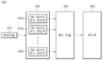
도 13을 참조하면, 데이터 처리 장치(400)는 측정 모듈(410), 데이터 처리 부(420), 통신 인터페이스부(430) 및 제어부(450)를 포함한다.Referring to FIG. 13, the
측정 모듈(410)은 고전압 직류 송전 시스템의 하나 이상의 지점에 대한 측정 값들을 획득한다. 일 실시 예에서 측정모듈(410)은 도 1 내지 도 2에서 도시된 고전압 직류 송전 시스템의 어느 한 지점에 대한 측정 값들을 획득할 수 있다. 측정 값들은 교류 파트(110, 170)의 일 지점에 대한 교류전압 및 교류 파트(110, 170)의 일 지점에 대한 교류전류를 포함할 수 있다. 또한, 측정 값들은 직류 송전 파트(140)의 직류전압 및 직류 송전 파트(140)의 일 지점에 대한 직류전류을 포함할 수 있다. 그러나, 이에 한정될 필요는 없고, 측정 값들은 고전압 직류 송전 시스템을 구성하는 구성요소의 입력단자의 전압/전류 또는 출력단자의 전압/전류를 포함할 수 있다.The
데이터 처리부(420)는 측정모듈(410)로부터 획득한 측정 값들을 이용하여 측정 데이터 유닛을 생성한다.The
데이터 처리부(420)는 복수의 데이터 유닛 생성부들(420a…420n)을 포함할 수 있고, 복수의 데이터 유닛 생성부들(420a…420n) 각각은 측정모듈(410)로부터 획득한 측정 값들을 이용하여 측정 데이터 유닛을 생성할 수 있다. 복수의 데이터 유닛 생성부들(420a…420n) 각각은 측정모듈(410)로부터 전달받은 측정 값들을 전처리(preprocessing)할 수 있다. 복수의 데이터 유닛 생성부들(420a…420n) 각각은 측정 값들을 제어부(450)가 측정 값들에 대한 유효 값을 추출하도록 불필요한 정보를 제거하는 예비적인 처리 과정을 수행할 수 있다. 복수의 데이터 유닛 생성부들(420a…420n) 각각은 전처리 과정을 수행하여 측정 데이터 유닛을 생성할 수 있다.The
복수의 데이터 유닛 생성부들(420a…420n) 각각은 자신이 생성한 측정 데이터 유닛을 시분할 다중화 방식을 통해 뒤따르는 데이터 유닛 생성부에 전송할 수 있다.Each of the plurality of
통신 모듈(430)은 전달받은 측정 데이터 유닛들을 파장 분할 다중화 방식을 이용하여 제어부(450)에 전송할 수 있다. 통신 모듈(430)은 복수의 측정 데이터 유닛들을 제어부(450)에 병렬적으로 전송할 수 있다. 통신 모듈(430)은 파장 분할 다중화(Wavelength Division Multiplexing, WDM) 방식을 이용하여 복수의 측정 데이터 유닛들을 제어부(450)에 전송할 수 있다. 파장 분할 다중화 방식은 복수의 파장 대역들 각각에 데이터를 할당하여 광섬유를 통해 전송하는 방식이다. 광섬유는 매우 넓은 주파수 영역에 걸쳐 많은 양의 데이터 전송이 가능하므로, 파장 분할 다중화 방식은 경제적이며, 전송 속도를 증가시키는 효과를 갖는다.The
파장 분할 다중화 방식을 도 14를 참조하여 설명한다.The wavelength division multiplexing method will be described with reference to FIG.
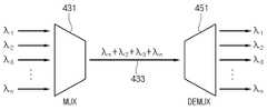
도 14는 본 발명의 실시 예에 따른 파장 분할 다중화 방식을 통해 데이터 전송 방법을 설명하기 위한 도면이다.FIG. 14 is a diagram for explaining a data transmission method using a wavelength division multiplexing method according to an embodiment of the present invention.
도 14를 참조하면, 통신 모듈(430)은 다중화부(431) 및 광섬유(433)를 포함할 수 있다. 도 14에서 광섬유(433)는 통신 모듈(430)에 포함된 것으로 설명되었으나, 이에 한정될 필요는 없고, 통신 모듈(430)과는 별도로 구성될 수 있다.Referring to FIG. 14, the
다중화부(431)는 복수의 파장 대역들(λ1,λ2, λ3,… λn)에 할당된 측정 데이터 유닛들을 다중화하여 하나의 데이터를 출력할 수 있다.The
광섬유(433)는 다중화부(431)로부터 출력된 하나의 데이터를 제어부(450)의 역다중화부(451)로 전달할 수 있다.The
역다중화부(451)는 다중화된 데이터를 복수의 파장 대역들로 역다중화 할 수 있다.The
다시 도 13을 설명한다.13 is described again.
통신 모듈(430)은 복수의 데이터 유닛 생성부들(420a…420n)로부터 전달받은 측정 데이터 유닛들 각각을 복수의 파장 대역들 각각에 할당하여 제어부(450)에 전송할 수 있다.The
일 실시 예에서 통신 모듈(430)은 하나의 광섬유를 통해 복수의 측정 데이터 유닛들을 제어부(450)에 전송할 수 있다. 광섬유는 코어 영역과 코어 영역을 둘러싸고 있는 클래딩 영역을 포함한다. 코어 영역에는 하나 이상의 코어들이 포함될 수 있다.In one embodiment, the
광섬유가 복수의 코어들을 포함하는 경우, 통신 모듈(430)은 복수의 코어들 각각에 측정 데이터 유닛을 할당하여 측정 데이터 유닛을 제어부(450)에 전송할 수 있다.When the optical fiber includes a plurality of cores, the
복수의 코어들 각각에는 복수의 파장 대역들이 할당될 수 있다. 복수의 코어들 각각은 동일한 복수의 파장 대역들이 할당될 수도 있다. 하나의 광섬유가 복수의 코어들을 포함하는 경우, 한꺼번에 많은 양의 데이터가 전송될 수 있다.A plurality of wavelength bands may be assigned to each of the plurality of cores. Each of the plurality of cores may be assigned the same plurality of wavelength bands. When one optical fiber includes a plurality of cores, a large amount of data can be transmitted at a time.
일 실시 예에서 복수의 코어들 각각은 데이터 처리부(420)를 구성하는 복수의 데이터 유닛 생성부들 각각에 대응할 수 있다. 이에 따라 복수의 코어들 각각은 복수의 데이터 유닛 생성부들 각각으로부터 측정 데이터 유닛을 제어부(450)에 전송할 수 있다.In one embodiment, each of the plurality of cores may correspond to each of the plurality of data unit generators constituting the
또 다른 실시 예에서 복수의 코어들 각각은 적어도 2 이상의 데이터 유닛 생성부들과 대응될 수 있다. 이 경우, 통신 모듈(430)은 복수의 코어들 각각에 파장 대역을 할당할 수 있고, 복수의 코어들 각각은 할당된 파장 대역을 통해 2 이상의 측정 데이터 유닛들을 제어부(450)에 전송할 수 있다.In another embodiment, each of the plurality of cores may correspond to at least two or more data unit generators. In this case, the
통신 모듈(430)은 복수의 코어들에 우선 순위를 정하여 정해진 우선 순위에 따라 측정 데이터 유닛을 전송할 수 있다. 구체적으로, 복수의 측정부들 중 어느 하나의 측정부에서 측정된 측정 값의 전송이 먼저 요구되는 경우, 통신 모듈(430)은 복수의 코어들 중 가장 우선 순위가 높은 코어를 통해 측정 데이터 유닛을 먼저 전송할 수 있다.The
제어부(450)는 데이터 처리 장치(400)의 동작을 전반적으로 제어할 수 있다.The
제어부(450)는 통신 모듈(430)로부터 전달받은 측정 데이터 유닛들을 코딩하여 외부에 제공할 수 있다.The
제어부(450)는 측정 데이터 유닛들을 2위상 코딩(bi-phase) 방식을 이용하여 코딩할 수 있다.The
도 15는 본 발명의 또 다른 실시 예에 따른 데이터 처리 장치의 실제 구성 예를 보여준다.FIG. 15 shows an actual configuration example of a data processing apparatus according to another embodiment of the present invention.
도 15를 참조하면, 제1 데이터 처리 장치(400_1) 및 제2 데이터 처리 장치(400_2)가 도시되어 있다. 제1 데이터 처리 장치(300_1) 및 제2 데이터 처리 장치(300_2) 각각의 구성은 도 13에서 설명한 것과 같다. 다만, 일부 구성요소는 생략했다.Referring to Fig. 15, a first data processing apparatus 400_1 and a second data processing apparatus 400_2 are shown. The configurations of the first data processing apparatus 300_1 and the second data processing apparatus 300_2 are the same as those described in FIG. However, some components are omitted.
제1 데이터 처리부(420_1)는 복수의 측정 데이터 유닛들을 제1 통신 모듈(430_1)에 전달한다.The first data processing unit 420_1 transmits a plurality of measurement data units to the first communication module 430_1.
제1 통신 모듈(430_1)은 전달받은 복수의 측정 데이터 유닛들을 파장 분할 다중화 방식을 이용하여 제1 제어부(450_1)에 전송한다.The first communication module 430_1 transmits the received plurality of measurement data units to the first controller 450_1 using the WDM scheme.
제2 데이터 처리부(420_2)는 복수의 측정 데이터 유닛들을 제2 통신 모듈(430_2)에 전달한다.The second data processing unit 420_2 transmits the plurality of measurement data units to the second communication module 430_2.
제2 통신 모듈(430_2)은 전달받은 복수의 측정 데이터 유닛들을 파장 분할 다중화 방식을 이용하여 제2 제어부(450_2)에 전송한다.The second communication module 430_2 transmits the received plurality of measurement data units to the second controller 450_2 using a wavelength division multiplexing method.
제1 제어부(450_1)는 제2 통신 모듈(430_2)로부터 제2 데이터 처리부(420_2)가 생성한 측정 데이터 유닛들을 수신할 수 있다. 이 경우에도, 파장 분할 다중화 방식이 사용될 수 있다.The first control unit 450_1 may receive measurement data units generated by the second data processing unit 420_2 from the second communication module 430_2. In this case as well, a wavelength division multiplexing scheme can be used.
제2 제어부(450_2)는 제1 통신 모듈(430_1)로부터 제1 데이터 처리부(420_1)가 생성한 측정 데이터 유닛들을 수신할 수 있다. 이 경우에도, 파장 분할 다중화 방식이 사용될 수 있다.The second control unit 450_2 may receive the measurement data units generated by the first data processing unit 420_1 from the first communication module 430_1. In this case as well, a wavelength division multiplexing scheme can be used.
각 제어부는 트리거에 기초하여 수신한 측정 데이터 유닛들을 외부에 제공할 수 있다. 트리거는 측정 데이터 패킷의 전송을 개시하는 동기일 수 있다.Each control unit can externally provide the received measurement data units based on the trigger. The trigger may be a synchronization to initiate transmission of the measurement data packet.
일 실시 예에서 트리거는 데이터 처리 장치(400)에 기 설정된 시간적 동기일 수 있다. 트리거는 일정 주기의 시간 마다 생성될 수 있다. 즉, 제어부(450)는 정해진 시간 간격 마다 측정 데이터 유닛들을 외부에 제공할 수 있다.In one embodiment, the trigger may be a predetermined temporal synchronization in the
또한, 트리거는 불규칙적인 시간 마다 생성될 수 있다. 제어부(450)는 불규칙적인 시간 간격 마다 측정 데이터 유닛들을 외부에 제공할 수 있다.In addition, triggers can be generated at irregular intervals. The
또 다른 실시 예에서 트리거는 다른 제어부의 요청일 수 있다. 즉, 예를 들어, 도 15에 도시된 제1 제어부(450_1)는 제2 제어부(450_2)의 요청에 의해 측정 데이터 유닛들을 제2 제어부(450_2)에 제공할 수 있다. 마찬가지로, 제2 제어부(450_2)는 제1 제어부(450_1)의 요청에 의해 측정 데이터 유닛들을 제1 제어부(450_1)에 제공할 수 있다.In yet another embodiment, the trigger may be a request from another control. That is, for example, the first controller 450_1 shown in FIG. 15 may provide the second data controller 450_2 with the measurement data units at the request of the second controller 450_2. Similarly, the second controller 450_2 may provide the measurement data units to the first controller 450_1 at the request of the first controller 450_1.
제1 제어부(450_1)는 제2 제어부(450_2)는 광섬유를 통해 측정 데이터 유닛들을 송수신할 수 있다.The first control unit 450_1 can transmit and receive the measurement data units through the optical fiber to the second control unit 450_2.
또 다른 실시 예에서 트리거는 사용자의 요청일 수 있다. 제어부(350)는 사용자의 요청에 따라 측정 데이터 유닛들을 사용자의 단말기에 제공할 수 있다. 여기서, 사용자의 단말기는 컴퓨터, 노트북, 스마트 폰 등과 같은 이동 단말기일 수 있으나, 이에 한정될 필요는 없다.In yet another embodiment, the trigger may be a user request. The
도 16은 본 발명의 또 다른 실시 예에 따른 데이터 처리 장치의 데이터 전송 방법을 설명하기 위한 흐름도이다.16 is a flowchart for explaining a data transfer method of a data processing apparatus according to another embodiment of the present invention.
도 16을 참조하면,데이터 처리 장치(400)의 측정모듈(410)은 고전압 직류 송전 시스템의 하나 이상의 지점에 대한 측정 값들을 획득한다(S201).Referring to FIG. 16,the
일 실시 예에서 측정모듈(410)은 도 1 내지 도 2에서 도시된 고전압 직류 송전 시스템의 어느 한 지점에 대한 측정 값들을 획득할 수 있다. 측정 값들은 교류 파트(110, 170)의 일 지점에 대한 교류전압 및 교류 파트(110, 170)의 일 지점에 대한 교류전류를 포함할 수 있다. 또한, 측정 값들은 직류 송전 파트(140)의 직류전압 및 직류 송전 파트(140)의 일 지점에 대한 직류전류를 포함할 수 있다. 그러나, 이에 한정될 필요는 없고, 측정 값들은 고전압 직류 송전 시스템을 구성하는 구성요소의 입력단자의 전압/전류 또는 출력단자의 전압/전류를 포함할 수 있다.In one embodiment, the
측정모듈(410)은 복수의 측정부들(미도시)를 포함할 수 있다. 복수의 측정부들 각각은 측정 값들을 복수의 데이터 유닛 생성부들(420a…420n)에 전달할 수 있다. 즉, 복수의 측정부들 각각은 복수의 데이터 유닛 생성부들(420a…420n) 각각에 대응할 수 있다.The
복수의 데이터 유닛 생성부들(420a…420n) 각각은 측정모듈(410)로부터 획득한 측정 값들을 이용하여 측정 데이터 유닛을 생성한다(S203).Each of the plurality of
복수의 데이터 유닛 생성부들(420a…420n) 각각은 측정모듈(410)로부터 전달받은 측정 값들을 전처리(preprocessing)할 수 있다. 복수의 데이터 유닛 생성부들(420a…420n) 각각은 측정 값들을 제어부(450)가 측정 값들에 대한 유효 값을 추출하도록 불필요한 정보를 제거하는 예비적인 처리 과정을 수행할 수 있다. 복수의 데이터 유닛 생성부들(420a…420n) 각각은 전처리 과정을 수행하여 측정 데이터 유닛을 생성할 수 있다.Each of the plurality of
복수의 데이터 유닛 생성부들(420a…420n) 각각은 생성된 측정 데이터 유닛을 통신 모듈(430)에 전달한다(S205).Each of the plurality of
통신 모듈(430)은 전달받은 측정 데이터 유닛들을 파장 분할 다중화 방식을 이용하여 제어부(450)에 전송한다(S207).The
통신 모듈(430)은 복수의 측정 데이터 유닛들을 제어부(450)에 병렬적으로 전송할 수 있다. 통신 모듈(430)은 파장 분할 다중화(Wavelength Division Multiplexing, WDM) 방식을 이용하여 복수의 측정 데이터 유닛들을 제어부(450)에 전송할 수 있다. 파장 분할 다중화 방식은 복수의 파장 대역들 각각에 데이터를 할당하여 광섬유를 통해 전송하는 방식이다. 광섬유는 매우 넓은 주파수 영역에 걸쳐 많은 양의 데이터 전송이 가능하므로, 파장 분할 다중화 방식은 경제적이며, 전송 속도를 증가시키는 효과를 갖는다.The
통신 모듈(430)은 복수의 데이터 유닛 생성부들(420a…420n)로부터 전달받은 측정 데이터 유닛들 각각을 복수의 파장 대역들 각각에 할당하여 제어부(450)에 전송할 수 있다.The
일 실시 예에서 통신 모듈(430)은 하나의 광섬유를 통해 복수의 측정 데이터 유닛들을 제어부(450)에 전송할 수 있다. 광섬유는 코어 영역과 코어 영역을 둘러싸고 있는 클래딩 영역을 포함한다. 코어 영역에는 하나 이상의 코어들이 포함될 수 있다.In one embodiment, the
광섬유가 복수의 코어들을 포함하는 경우, 통신 모듈(430)은 복수의 코어들 각각에 측정 데이터 유닛을 할당하여 측정 데이터 유닛을 제어부(450)에 전송할 수 있다.When the optical fiber includes a plurality of cores, the
복수의 코어들 각각에는 복수의 파장 대역들이 할당될 수 있다. 복수의 코어들 각각은 동일한 복수의 파장 대역들이 할당될 수도 있다. 하나의 광섬유가 복수의 코어들을 포함하는 경우, 한꺼번에 많은 양의 데이터가 전송될 수 있다.A plurality of wavelength bands may be assigned to each of the plurality of cores. Each of the plurality of cores may be assigned the same plurality of wavelength bands. When one optical fiber includes a plurality of cores, a large amount of data can be transmitted at a time.
일 실시 예에서 복수의 코어들 각각은 데이터 처리부(420)를 구성하는 복수의 데이터 유닛 생성부들 각각에 대응할 수 있다. 이에 따라 복수의 코어들 각각은 복수의 데이터 유닛 생성부들 각각으로부터 측정 데이터 유닛을 제어부(450)에 전송할 수 있다.In one embodiment, each of the plurality of cores may correspond to each of the plurality of data unit generators constituting the
또 다른 실시 예에서 복수의 코어들 각각은 적어도 2 이상의 데이터 유닛 생성부들과 대응될 수 있다. 이 경우, 통신 모듈(430)은 복수의 코어들 각각에 파장 대역을 할당할 수 있고, 복수의 코어들 각각은 할당된 파장 대역을 통해 2 이상의 측정 데이터 유닛들을 제어부(450)에 전송할 수 있다.In another embodiment, each of the plurality of cores may correspond to at least two or more data unit generators. In this case, the
통신 모듈(430)은 복수의 코어들에 우선 순위를 정하여 정해진 우선 순위에 따라 측정 데이터 유닛을 전송할 수 있다. 구체적으로, 복수의 측정부들 중 어느 하나의 측정부에서 측정된 측정 값의 전송이 먼저 요구되는 경우, 통신 모듈(430)은 복수의 코어들 중 가장 우선 순위가 높은 코어를 통해 측정 데이터 유닛을 먼저 전송할 수 있다.The
시분할 다중화(TDM) 방식의 경우, 데이터 유닛 생성부의 개수가 많아질수록 채널의 병목률이 증가하고, 전송 동기에 민감한 문제가 있다. 또한, 시분할 다중화 방식의 경우, 데이터의 전송 속도를 빠르게 해야만이 시스템의 요구 사항을 충족시킬 수 있는 문제가 있다.In the case of the time division multiplexing (TDM) scheme, the bottleneck rate of the channel increases as the number of the data unit generators increases, and there is a problem of being sensitive to the transmission synchronization. Further, in the case of the time division multiplexing method, there is a problem that the data transmission speed must be increased to meet the requirements of the system.
그러나, 본 발명의 실시 예에 따른 데이터 처리 장치(400)는 각 측정 데이터 유닛을 특정 파장 대역에 할당하여 병렬적으로 전송하므로, 데이터 유닛 생성부의 개수가 많더라도 채널의 병목률을 낮출 수 있고, 데이터의 전송 속도를 빠르게 하지 않아도 시스템 요구 사항을 충족시킬 수 있다.However, since the
제어부(450)는 통신 모듈(430)로부터 전달받은 측정 데이터 유닛들을 코딩하여 외부에 제공한다(S209).The
본 발명의 일 실시예에 의하면, 전술한 방법은, 프로그램이 기록된 매체에 프로세서가 읽을 수 있는 코드로서 구현하는 것이 가능하다. 프로세서가 읽을 수 있는 매체의 예로는, ROM, RAM, CD-ROM, 자기 테이프, 플로피 디스크, 광 데이터 저장장치 등이 있으며, 캐리어 웨이브(예를 들어, 인터넷을 통한 전송)의 형태로 구현되는 것도 포함한다.According to an embodiment of the present invention, the above-described method can be implemented as a code readable by a processor on a medium on which a program is recorded. Examples of the medium that can be read by the processor include ROM, RAM, CD-ROM, magnetic tape, floppy disk, optical data storage, etc., and may be implemented in the form of a carrier wave (e.g., transmission over the Internet) .
상기와 같이 기재된 실시예들은 설명된 구성과 방법이 한정되게 적용될 수 있는 것이 아니라, 실시예들은 다양한 변형이 이루어질 수 있도록 각 실시예들의 전부 또는 일부가 선택적으로 조합되어 구성될 수도 있다.The embodiments described above are not limited to the configurations and methods described above, but the embodiments may be configured by selectively combining all or a part of the embodiments so that various modifications can be made.
Claims (9)
Translated fromKorean상기 고전압 직류 송전 시스템의 하나 이상의 지점에 대해 전압 또는 전류를 측정하는 측정 모듈;
상기 측정 모듈에서 측정된 측정 값들을 이용하여 측정 데이터 유닛들을 생성하는 데이터 처리부; 및
상기 복수의 측정 데이터 유닛들을 파장 분할 다중화 방식을 이용하여 하나의 광섬유를 통해 외부에 전송하는 통신 모듈을 포함하고,
상기 광섬유는
복수의 코어들을 포함하는
고전압 직류 송전 시스템의 데이터 처리 장치.A data processing apparatus for a high-voltage DC transmission system,
A measurement module for measuring voltage or current for at least one point of the high voltage DC transmission system;
A data processing unit for generating measurement data units using the measurement values measured by the measurement module; And
And a communication module for transmitting the plurality of measurement data units to the outside via one optical fiber using a wavelength division multiplexing method,
The optical fiber
Comprising a plurality of cores
Data processing apparatus for high voltage DC transmission system.
상기 복수의 코어들 각각은 하나 이상의 측정 데이터 유닛들에 대응되고,
상기 통신 모듈은
상기 복수의 코어들 각각을 통해 상기 복수의 측정 데이터 유닛들을 외부에 전송하는
고전압 직류 송전 시스템의 데이터 처리 장치.The method according to claim 1,
Each of the plurality of cores corresponding to one or more measurement data units,
The communication module
And transmitting the plurality of measurement data units to the outside via each of the plurality of cores
Data processing apparatus for high voltage DC transmission system.
상기 데이터 처리부는
복수의 데이터 유닛 생성부들을 포함하고,
상기 복수의 데이터 유닛 생성부들 각각은
상기 측정 모듈에서 측정된 측정 값들을 이용하여 측정 데이터 유닛을 생성하고, 생성된 측정 데이터 유닛을 상기 통신 모듈에 전달하는
고전압 직류 송전 시스템의 데이터 처리 장치.3. The method of claim 2,
The data processing unit
A plurality of data unit generators,
Each of the plurality of data unit generators
Generating a measurement data unit using the measured values measured by the measurement module, and transmitting the generated measurement data unit to the communication module
Data processing apparatus for high voltage DC transmission system.
상기 복수의 코어들 각각은
상기 데이터 처리부를 구성하는 복수의 데이터 유닛 생성부들 각각에 대응하는
고전압 직류 송전 시스템의 데이터 처리 장치.The method of claim 3,
Each of the plurality of cores
A plurality of data unit generators corresponding to each of the plurality of data unit generators constituting the data processing unit
Data processing apparatus for high voltage DC transmission system.
상기 복수의 코어들 각각은 적어도 2 이상의 데이터 유닛 생성부들과 대응하는
고전압 직류 송전 시스템의 데이터 처리 장치.The method of claim 3,
Wherein each of the plurality of cores has at least two data unit generators
Data processing apparatus for high voltage DC transmission system.
상기 통신 모듈은
상기 복수의 측정 데이터 유닛들을 하나의 광섬유를 통해 병렬적으로 전송하는
고전압 직류 송전 시스템의 데이터 처리 장치.The method according to claim 1,
The communication module
And transmitting the plurality of measurement data units in parallel through one optical fiber
Data processing apparatus for high voltage DC transmission system.
상기 통신 모듈은
상기 복수의 측정 데이터 유닛들 각각에 복수의 파장 대역들 각각을 할당하여 상기 복수의 측정 데이터 유닛들을 전송하는
고전압 직류 송전 시스템의 데이터 처리 장치.The method according to claim 6,
The communication module
Wherein each of the plurality of measurement data units is allocated to each of a plurality of wavelength bands to transmit the plurality of measurement data units
Data processing apparatus for high voltage DC transmission system.
상기 복수의 측정 데이터 유닛들을 코딩하여 외부에 전송하는 제어부를 더 포함하는
고전압 직류 송전 시스템의 데이터 처리 장치.The method according to claim 1,
And a control unit for coding and transmitting the plurality of measurement data units to the outside
Data processing apparatus for high voltage DC transmission system.
상기 복수의 데이터 유닛 생성부들 각각은
상기 측정 모듈에서 측정된 측정 값들을 전처리하여 전처리된 측정 데이터 유닛을 생성하는
고전압 직류 송전 시스템의 데이터 처리 장치.The method of claim 3,
Each of the plurality of data unit generators
Preprocessing the measurement values measured by the measurement module to generate a preprocessed measurement data unit
Data processing apparatus for high voltage DC transmission system.
Priority Applications (6)
| Application Number | Priority Date | Filing Date | Title |
|---|---|---|---|
| KR1020140058072AKR101596139B1 (en) | 2014-05-14 | 2014-05-14 | Data processing device for high voltage direct current transmission system and method thereof |
| ES15165674TES2708029T3 (en) | 2014-05-14 | 2015-04-29 | Device and data processing procedure for the high voltage direct current transmission system |
| EP15165674.1AEP2945396B1 (en) | 2014-05-14 | 2015-04-29 | Data processing device and method for high voltage direct current transmission system |
| US14/711,587US10211749B2 (en) | 2014-05-14 | 2015-05-13 | Data processing device and method for high voltage direct current transmission system |
| CN201510350118.1ACN105098827B (en) | 2014-05-14 | 2015-05-13 | For the data processing equipment and method of HVDC transmission system |
| JP2015099206AJP6082050B2 (en) | 2014-05-14 | 2015-05-14 | Data processing apparatus and method for high voltage DC power transmission system |
Applications Claiming Priority (1)
| Application Number | Priority Date | Filing Date | Title |
|---|---|---|---|
| KR1020140058072AKR101596139B1 (en) | 2014-05-14 | 2014-05-14 | Data processing device for high voltage direct current transmission system and method thereof |
Publications (2)
| Publication Number | Publication Date |
|---|---|
| KR20150130879Atrue KR20150130879A (en) | 2015-11-24 |
| KR101596139B1 KR101596139B1 (en) | 2016-02-19 |
Family
ID=53191473
Family Applications (1)
| Application Number | Title | Priority Date | Filing Date |
|---|---|---|---|
| KR1020140058072AExpired - Fee RelatedKR101596139B1 (en) | 2014-05-14 | 2014-05-14 | Data processing device for high voltage direct current transmission system and method thereof |
Country Status (6)
| Country | Link |
|---|---|
| US (1) | US10211749B2 (en) |
| EP (1) | EP2945396B1 (en) |
| JP (1) | JP6082050B2 (en) |
| KR (1) | KR101596139B1 (en) |
| CN (1) | CN105098827B (en) |
| ES (1) | ES2708029T3 (en) |
Families Citing this family (2)
| Publication number | Priority date | Publication date | Assignee | Title |
|---|---|---|---|---|
| KR102505454B1 (en) | 2016-04-28 | 2023-03-03 | 엘에스일렉트릭(주) | Static Var Compensator of controller system and Controlling Method Thereof |
| CN107422166B (en)* | 2017-08-07 | 2020-02-11 | 北京航天时代光电科技有限公司 | Modulation and demodulation method for suppressing light power fluctuation for optical fiber current transformer |
Citations (4)
| Publication number | Priority date | Publication date | Assignee | Title |
|---|---|---|---|---|
| KR20010112222A (en)* | 1998-11-30 | 2001-12-20 | 추후보정 | Method and software for user interface device in a last mile telecommunications cabling |
| KR20060083367A (en)* | 2005-01-14 | 2006-07-20 | 한전케이디엔 주식회사 | Data collection device of remote meter reading system |
| KR20140032494A (en)* | 2011-08-08 | 2014-03-14 | 닛토덴코 가부시키가이샤 | Smart tap |
| KR20140032567A (en)* | 2012-09-06 | 2014-03-17 | 현대중공업 주식회사 | System of monitoring transmission line |
Family Cites Families (35)
| Publication number | Priority date | Publication date | Assignee | Title |
|---|---|---|---|---|
| JPS61278226A (en) | 1985-06-03 | 1986-12-09 | Sumitomo Electric Ind Ltd | Information transmission system using optical fiber cable |
| JPH01150871A (en) | 1987-12-07 | 1989-06-13 | Sumitomo Electric Ind Ltd | Transmission line fault detection system structure |
| JPH0425243A (en)* | 1990-05-18 | 1992-01-29 | Hitachi Cable Ltd | Wavelength multiplex signal receiving method |
| US5596671A (en)* | 1994-04-28 | 1997-01-21 | Rockwell, Iii; Marshall A. | Optical waveguide display system |
| JPH0819168A (en) | 1994-06-30 | 1996-01-19 | Mitsubishi Electric Corp | Method and device for protection relay of DC transmission line |
| US6584245B1 (en)* | 1996-05-06 | 2003-06-24 | Teracomm Research, Inc | High speed data link including a superconductive plate assembly for use in a data transmission scheme and method |
| JPH09312934A (en) | 1996-05-21 | 1997-12-02 | Hitachi Ltd | Power system stabilizer for power system |
| WO2004100624A2 (en)* | 2003-05-05 | 2004-11-18 | Color Kinetics, Inc. | Lighting methods and systems |
| JP2006050519A (en) | 2003-10-24 | 2006-02-16 | Sony Corp | Wireless communications system, wireless communications apparatus, wireless communication method, and computer program |
| JP4494401B2 (en)* | 2004-03-17 | 2010-06-30 | 日本電信電話株式会社 | Optical transmission system, optical transmission device and optical reception device of optical transmission system |
| US7646029B2 (en)* | 2004-07-08 | 2010-01-12 | Philips Solid-State Lighting Solutions, Inc. | LED package methods and systems |
| EP1886434B1 (en)* | 2005-06-02 | 2010-03-17 | Siemens Aktiengesellschaft | Method for transmitting data for controlling an hvdc system |
| EP1886151B1 (en)* | 2005-06-02 | 2019-07-24 | Siemens Aktiengesellschaft | Apparatus for detecting and processing a multiplicity of measured values in an hvdct system |
| CN1881744B (en)* | 2005-06-16 | 2010-05-12 | 许继集团有限公司 | Realization method of a real-time monitoring system for HVDC converter station |
| DE112005003781A5 (en)* | 2005-09-22 | 2008-08-28 | Siemens Aktiengesellschaft | Control method for DC transmission |
| JP2008039929A (en)* | 2006-08-02 | 2008-02-21 | Nec Corp | Optical transmission system, optical transmitter, optical transmission method and optical transmission program |
| JP5168685B2 (en)* | 2007-09-18 | 2013-03-21 | 独立行政法人情報通信研究機構 | Quadrature amplitude modulation signal generator |
| DE602008004448D1 (en)* | 2008-05-08 | 2011-02-24 | Areva T & D Messwandler Gmbh | Active current sensor and current measuring device |
| RU2481682C2 (en)* | 2008-07-30 | 2013-05-10 | Абб Рисерч Лтд | Substation of ac to dc transformation or dc to high-voltage ac transformation with fibre-optic current sensor |
| BRPI1003307A2 (en)* | 2010-05-21 | 2012-02-07 | Furnas Centrais Eletricas S A | device, system and method for monitoring grounding electrode lines |
| RU2553757C2 (en)* | 2010-05-28 | 2015-06-20 | Статойл Петролеум Ас | System of hydrocarbons underwater production |
| CN101893670B (en)* | 2010-06-25 | 2013-12-18 | 中国电力科学研究院 | Photoelectric measurement system for high-voltage direct current power transmission converter valve |
| KR101433856B1 (en)* | 2010-07-21 | 2014-08-27 | 한국전자통신연구원 | optical switch and manufacturing method of the same |
| US20120189303A1 (en)* | 2011-01-24 | 2012-07-26 | Winzer Peter J | Optical transport multiplexing client traffic onto parallel line system paths |
| WO2013013282A1 (en)* | 2011-07-22 | 2013-01-31 | HYDRO-QUéBEC | Switching apparatus, control system and method for varying an impedance of a phase line |
| US8886476B1 (en)* | 2011-09-22 | 2014-11-11 | Cisco Technology, Inc. | Multi-terminal protection using phasor measurement unit networks |
| GB2500717A (en)* | 2012-03-30 | 2013-10-02 | Stingray Geophysical Ltd | Optical sensing system with amplification |
| US9197356B2 (en)* | 2012-11-16 | 2015-11-24 | At&T Intellectual Property I, L.P. | Distributed spatial mode processing for spatial-mode multiplexed communication systems |
| JP6043652B2 (en)* | 2013-02-22 | 2016-12-14 | 株式会社日立製作所 | Large capacity fiber optic switching device and optical transmission system |
| US10310006B2 (en)* | 2013-03-15 | 2019-06-04 | Hubbell Incorporated | DC high potential insulation breakdown test system and method |
| CN103731209A (en)* | 2013-12-05 | 2014-04-16 | 国家电网公司 | Single-optical-fiber bidirectional communication method for high-voltage direct current transmission |
| PL226046B1 (en)* | 2013-12-15 | 2017-06-30 | Inphotech Spółka Z Ograniczoną Odpowiedzialnością | Microstructural multicore optical fiber, device for independent addressing of the cores of a multicore microstructured optical fiber and the implementation of a device for the independent addressing of the cores of a multicore microstructured fiber |
| JP2015149577A (en)* | 2014-02-06 | 2015-08-20 | 株式会社日立製作所 | Bandwidth control device |
| US20170019178A1 (en)* | 2014-02-24 | 2017-01-19 | The Regents Of The University Of California | Nonlinearity cancellation in fiber optic transmission based on frequency-mutually-referenced carriers |
| US9509399B2 (en)* | 2015-02-13 | 2016-11-29 | Schweitzer Engineering Laboratories, Inc. | Transmission line protection using traveling waves in optical ground wire fiber |
- 2014
- 2014-05-14KRKR1020140058072Apatent/KR101596139B1/ennot_activeExpired - Fee Related
- 2015
- 2015-04-29EPEP15165674.1Apatent/EP2945396B1/ennot_activeNot-in-force
- 2015-04-29ESES15165674Tpatent/ES2708029T3/enactiveActive
- 2015-05-13CNCN201510350118.1Apatent/CN105098827B/ennot_activeExpired - Fee Related
- 2015-05-13USUS14/711,587patent/US10211749B2/ennot_activeExpired - Fee Related
- 2015-05-14JPJP2015099206Apatent/JP6082050B2/ennot_activeExpired - Fee Related
Patent Citations (4)
| Publication number | Priority date | Publication date | Assignee | Title |
|---|---|---|---|---|
| KR20010112222A (en)* | 1998-11-30 | 2001-12-20 | 추후보정 | Method and software for user interface device in a last mile telecommunications cabling |
| KR20060083367A (en)* | 2005-01-14 | 2006-07-20 | 한전케이디엔 주식회사 | Data collection device of remote meter reading system |
| KR20140032494A (en)* | 2011-08-08 | 2014-03-14 | 닛토덴코 가부시키가이샤 | Smart tap |
| KR20140032567A (en)* | 2012-09-06 | 2014-03-17 | 현대중공업 주식회사 | System of monitoring transmission line |
Also Published As
| Publication number | Publication date |
|---|---|
| JP2015220994A (en) | 2015-12-07 |
| CN105098827B (en) | 2018-05-18 |
| ES2708029T3 (en) | 2019-04-08 |
| JP6082050B2 (en) | 2017-02-15 |
| US10211749B2 (en) | 2019-02-19 |
| CN105098827A (en) | 2015-11-25 |
| EP2945396A2 (en) | 2015-11-18 |
| EP2945396A3 (en) | 2015-11-25 |
| EP2945396B1 (en) | 2018-10-24 |
| US20150333651A1 (en) | 2015-11-19 |
| KR101596139B1 (en) | 2016-02-19 |
Similar Documents
| Publication | Publication Date | Title |
|---|---|---|
| KR101596137B1 (en) | Data processing device for high voltage direct current transmission system and method thereof | |
| KR101596138B1 (en) | Data processing device for high voltage direct current transmission system and method thereof | |
| KR101596139B1 (en) | Data processing device for high voltage direct current transmission system and method thereof | |
| KR101596136B1 (en) | Data processing device for high voltage direct current transmission system and method thereof | |
| KR101596134B1 (en) | Data processing device for high voltage direct current transmission system and method thereof | |
| KR101596135B1 (en) | Data processing device for high voltage direct current transmission system and method thereof | |
| KR101667886B1 (en) | Data control system | |
| JP6110535B2 (en) | Data processing apparatus and method for high voltage DC power transmission system |
Legal Events
| Date | Code | Title | Description |
|---|---|---|---|
| A201 | Request for examination | ||
| PA0109 | Patent application | St.27 status event code:A-0-1-A10-A12-nap-PA0109 | |
| PA0201 | Request for examination | St.27 status event code:A-1-2-D10-D11-exm-PA0201 | |
| R18-X000 | Changes to party contact information recorded | St.27 status event code:A-3-3-R10-R18-oth-X000 | |
| R17-X000 | Change to representative recorded | St.27 status event code:A-3-3-R10-R17-oth-X000 | |
| E902 | Notification of reason for refusal | ||
| PE0902 | Notice of grounds for rejection | St.27 status event code:A-1-2-D10-D21-exm-PE0902 | |
| PG1501 | Laying open of application | St.27 status event code:A-1-1-Q10-Q12-nap-PG1501 | |
| E13-X000 | Pre-grant limitation requested | St.27 status event code:A-2-3-E10-E13-lim-X000 | |
| P11-X000 | Amendment of application requested | St.27 status event code:A-2-2-P10-P11-nap-X000 | |
| P13-X000 | Application amended | St.27 status event code:A-2-2-P10-P13-nap-X000 | |
| E701 | Decision to grant or registration of patent right | ||
| PE0701 | Decision of registration | St.27 status event code:A-1-2-D10-D22-exm-PE0701 | |
| PR0701 | Registration of establishment | St.27 status event code:A-2-4-F10-F11-exm-PR0701 | |
| PR1002 | Payment of registration fee | St.27 status event code:A-2-2-U10-U11-oth-PR1002 Fee payment year number:1 | |
| PG1601 | Publication of registration | St.27 status event code:A-4-4-Q10-Q13-nap-PG1601 | |
| FPAY | Annual fee payment | Payment date:20190121 Year of fee payment:4 | |
| PR1001 | Payment of annual fee | St.27 status event code:A-4-4-U10-U11-oth-PR1001 Fee payment year number:4 | |
| FPAY | Annual fee payment | Payment date:20200102 Year of fee payment:5 | |
| PR1001 | Payment of annual fee | St.27 status event code:A-4-4-U10-U11-oth-PR1001 Fee payment year number:5 | |
| PN2301 | Change of applicant | St.27 status event code:A-5-5-R10-R13-asn-PN2301 St.27 status event code:A-5-5-R10-R11-asn-PN2301 | |
| PC1903 | Unpaid annual fee | St.27 status event code:A-4-4-U10-U13-oth-PC1903 Not in force date:20210216 Payment event data comment text:Termination Category : DEFAULT_OF_REGISTRATION_FEE | |
| PC1903 | Unpaid annual fee | St.27 status event code:N-4-6-H10-H13-oth-PC1903 Ip right cessation event data comment text:Termination Category : DEFAULT_OF_REGISTRATION_FEE Not in force date:20210216 | |
| PN2301 | Change of applicant | St.27 status event code:A-5-5-R10-R13-asn-PN2301 St.27 status event code:A-5-5-R10-R11-asn-PN2301 | |
| R18-X000 | Changes to party contact information recorded | St.27 status event code:A-5-5-R10-R18-oth-X000 |