KR20150127964A - A hybrid deodorizing device - Google Patents
A hybrid deodorizing deviceDownload PDFInfo
- Publication number
- KR20150127964A KR20150127964AKR1020140054549AKR20140054549AKR20150127964AKR 20150127964 AKR20150127964 AKR 20150127964AKR 1020140054549 AKR1020140054549 AKR 1020140054549AKR 20140054549 AKR20140054549 AKR 20140054549AKR 20150127964 AKR20150127964 AKR 20150127964A
- Authority
- KR
- South Korea
- Prior art keywords
- deodorization
- module
- odor
- pipe
- hybrid
- Prior art date
- Legal status (The legal status is an assumption and is not a legal conclusion. Google has not performed a legal analysis and makes no representation as to the accuracy of the status listed.)
- Ceased
Links
- 230000001877deodorizing effectEffects0.000titleabstractdescription6
- 238000004332deodorizationMethods0.000claimsabstractdescription176
- XLYOFNOQVPJJNP-UHFFFAOYSA-NwaterSubstancesOXLYOFNOQVPJJNP-UHFFFAOYSA-N0.000claimsabstractdescription61
- 238000002347injectionMethods0.000claimsdescription16
- 239000007924injectionSubstances0.000claimsdescription16
- 238000000034methodMethods0.000claimsdescription15
- 230000003647oxidationEffects0.000claimsdescription7
- 238000007254oxidation reactionMethods0.000claimsdescription7
- 238000004891communicationMethods0.000claimsdescription4
- 230000001678irradiating effectEffects0.000claimsdescription2
- 235000019645odorNutrition0.000abstractdescription42
- 239000002131composite materialSubstances0.000abstractdescription2
- 230000008014freezingEffects0.000abstract1
- 238000007710freezingMethods0.000abstract1
- 244000005700microbiomeSpecies0.000description4
- 238000010586diagramMethods0.000description3
- 238000001035dryingMethods0.000description3
- 239000012530fluidSubstances0.000description3
- 230000008569processEffects0.000description3
- OKTJSMMVPCPJKN-UHFFFAOYSA-NCarbonChemical compound[C]OKTJSMMVPCPJKN-UHFFFAOYSA-N0.000description2
- VYPSYNLAJGMNEJ-UHFFFAOYSA-NSilicium dioxideChemical compoundO=[Si]=OVYPSYNLAJGMNEJ-UHFFFAOYSA-N0.000description2
- 239000003610charcoalSubstances0.000description2
- 238000000354decomposition reactionMethods0.000description2
- 238000012423maintenanceMethods0.000description2
- 239000000741silica gelSubstances0.000description2
- 229910002027silica gelInorganic materials0.000description2
- 239000007921spraySubstances0.000description2
- 239000000126substanceSubstances0.000description2
- RYGMFSIKBFXOCR-UHFFFAOYSA-NCopperChemical compound[Cu]RYGMFSIKBFXOCR-UHFFFAOYSA-N0.000description1
- 239000005708Sodium hypochloriteSubstances0.000description1
- 229910021536ZeoliteInorganic materials0.000description1
- CCKOTZKIYZRJBN-UHFFFAOYSA-N[O-2].O.S.[Fe+2]Chemical compound[O-2].O.S.[Fe+2]CCKOTZKIYZRJBN-UHFFFAOYSA-N0.000description1
- 230000009471actionEffects0.000description1
- 230000008859changeEffects0.000description1
- 229910052802copperInorganic materials0.000description1
- 239000010949copperSubstances0.000description1
- 230000000249desinfective effectEffects0.000description1
- 239000003085diluting agentSubstances0.000description1
- HNPSIPDUKPIQMN-UHFFFAOYSA-Ndioxosilane;oxo(oxoalumanyloxy)alumaneChemical compoundO=[Si]=O.O=[Al]O[Al]=OHNPSIPDUKPIQMN-UHFFFAOYSA-N0.000description1
- 238000003912environmental pollutionMethods0.000description1
- 238000009434installationMethods0.000description1
- 230000007257malfunctionEffects0.000description1
- 239000000463materialSubstances0.000description1
- 230000000813microbial effectEffects0.000description1
- 238000012986modificationMethods0.000description1
- 230000004048modificationEffects0.000description1
- 235000010204pine barkNutrition0.000description1
- 238000012545processingMethods0.000description1
- 239000010865sewageSubstances0.000description1
- SUKJFIGYRHOWBL-UHFFFAOYSA-Nsodium hypochloriteChemical compound[Na+].Cl[O-]SUKJFIGYRHOWBL-UHFFFAOYSA-N0.000description1
- 238000001179sorption measurementMethods0.000description1
- 238000005507sprayingMethods0.000description1
- 238000004065wastewater treatmentMethods0.000description1
- 239000010457zeoliteSubstances0.000description1
Images


Classifications
- C—CHEMISTRY; METALLURGY
- C02—TREATMENT OF WATER, WASTE WATER, SEWAGE, OR SLUDGE
- C02F—TREATMENT OF WATER, WASTE WATER, SEWAGE, OR SLUDGE
- C02F1/00—Treatment of water, waste water, or sewage
- C02F1/30—Treatment of water, waste water, or sewage by irradiation
- C02F1/32—Treatment of water, waste water, or sewage by irradiation with ultraviolet light
- A—HUMAN NECESSITIES
- A61—MEDICAL OR VETERINARY SCIENCE; HYGIENE
- A61L—METHODS OR APPARATUS FOR STERILISING MATERIALS OR OBJECTS IN GENERAL; DISINFECTION, STERILISATION OR DEODORISATION OF AIR; CHEMICAL ASPECTS OF BANDAGES, DRESSINGS, ABSORBENT PADS OR SURGICAL ARTICLES; MATERIALS FOR BANDAGES, DRESSINGS, ABSORBENT PADS OR SURGICAL ARTICLES
- A61L9/00—Disinfection, sterilisation or deodorisation of air
- A61L9/16—Disinfection, sterilisation or deodorisation of air using physical phenomena
- A61L9/18—Radiation
- A61L9/20—Ultraviolet radiation
- A—HUMAN NECESSITIES
- A61—MEDICAL OR VETERINARY SCIENCE; HYGIENE
- A61L—METHODS OR APPARATUS FOR STERILISING MATERIALS OR OBJECTS IN GENERAL; DISINFECTION, STERILISATION OR DEODORISATION OF AIR; CHEMICAL ASPECTS OF BANDAGES, DRESSINGS, ABSORBENT PADS OR SURGICAL ARTICLES; MATERIALS FOR BANDAGES, DRESSINGS, ABSORBENT PADS OR SURGICAL ARTICLES
- A61L2209/00—Aspects relating to disinfection, sterilisation or deodorisation of air
- A61L2209/10—Apparatus features
- A61L2209/14—Filtering means
- C—CHEMISTRY; METALLURGY
- C02—TREATMENT OF WATER, WASTE WATER, SEWAGE, OR SLUDGE
- C02F—TREATMENT OF WATER, WASTE WATER, SEWAGE, OR SLUDGE
- C02F2303/00—Specific treatment goals
- C02F2303/02—Odour removal or prevention of malodour
- C—CHEMISTRY; METALLURGY
- C02—TREATMENT OF WATER, WASTE WATER, SEWAGE, OR SLUDGE
- C02F—TREATMENT OF WATER, WASTE WATER, SEWAGE, OR SLUDGE
- C02F2303/00—Specific treatment goals
- C02F2303/04—Disinfection
Landscapes
- Health & Medical Sciences (AREA)
- Life Sciences & Earth Sciences (AREA)
- Veterinary Medicine (AREA)
- Animal Behavior & Ethology (AREA)
- General Health & Medical Sciences (AREA)
- Public Health (AREA)
- Epidemiology (AREA)
- Toxicology (AREA)
- Hydrology & Water Resources (AREA)
- Engineering & Computer Science (AREA)
- Environmental & Geological Engineering (AREA)
- Water Supply & Treatment (AREA)
- Chemical & Material Sciences (AREA)
- Organic Chemistry (AREA)
- Disinfection, Sterilisation Or Deodorisation Of Air (AREA)
Abstract
Translated fromKorean
Description
Translated fromKorean본 발명은 악취탈취장치에 관한 것으로서, 보다 상세하게는 상황에 따라 건식탈취모듈만 적용하거나 건식탈취모듈과 습식탈취모듈을 동시에 적용하여 효율적으로 악취를 탈취하는 하이브리드 악취탈취장치에 관한 것이다.
The present invention relates to a malodor deodorization apparatus, and more particularly, to a hybrid malodor deodorization apparatus that applies only a dry deodorization module or a deodorization module to both a dry deodorization module and a wet deodorization module at the same time.
기존의 하,폐수처리장치에는 처리과정에서 발생되는 악취를 흡착식, 화학적 처리식, 생물학적 분해방식 등 다양한 처리방식의 탈취장치에 의하여 처리되고 있으나 대부분의 탈취방식은 설치부지 및 초기 투자비용과 유지관리비용 등 여러가지 문제점으로 인하여 투자 비용만큼의 기대치를 얻지 못하고 있는 실정일 뿐만 아니라 안정적인 운전상태를 유지하기 위해서는 지속적인 관리와 비용이 요구되어 많은 인적, 물적 지원이 소요되고 있다.In the existing sewage and wastewater treatment system, the odor generated in the treatment process is treated by a deodorizing device of various treatment methods such as adsorption type, chemical treatment type, and biological decomposition type. However, most of the deodorization type is the installation site and initial investment cost and maintenance Cost and other problems, it is not only the situation where the investment cost is not expected, but also maintenance and cost are required to maintain the stable driving condition, so that a lot of human and material support is required.
기존의 탈취방법 중 보편적으로 사용되고 있는 생물학적 분해방식인 바이오 필터에 의한 탈취장치에 대하여 살펴보면,A deodorization device using a bio-filter, which is a biological decomposition method commonly used in conventional deodorization methods,
중간부에 담체를 구성하면서 공급수를 일정시간 간격으로 또는 지속적으로 살수하여 습도를 유지하도록 구성한 탈취탑에 포집된 악취가 악취 공급관을 통해 하부 공간에 유입시키도록 하여 악취가 체류하며 미생물이 식종되어 있는 담체와 접촉하면서 미생물에 의해 악취가 분해되는 과정을 거치면서 상승되어 악취가 제거되도록 한 것이다.The malodor collected in the deodorizing tower configured to maintain the humidity by continuously supplying the water at a predetermined time interval while forming the carrier in the middle portion flows into the lower space through the odor supply pipe, and the odor stays and the microorganisms are imitated And the odor is elevated while the odor is decomposed by the microorganism in contact with the carrier, thereby removing the odor.
이러한 미생물을 이용한 탈취장치인 바이오필터는 온도변화에 따른 미생물의 탈취기능의 변화를 갖는 문제점이 있는 것으로, 즉 온도가 낮은 동절기에는 미생물의 활동성이 상당히 낮아 정상적인 악취의 분해작용이 이루어지지 못한 상태로 외부로 배출되므로 환경오염 등을 유발시키는 등의 문제점이 있었다.The biofilter, which is a deodorizer using such a microorganism, has a problem in that the deodorizing function of the microorganism is changed according to the temperature change. That is, the microbial activity is considerably low during the low temperature season, There is a problem that it causes environmental pollution and the like.
또한, 탈취기의 악취처리 능력 이상의 고농도 악취가 유입될 경우 이에 대처할 수 있도록 농도에 적합한 처리 운전시스템 등이 구비되지 못하여 비효율적으로 운전되고 있는 실정이다.
In addition, in order to cope with a high concentration odor exceeding the malodor processing ability of the deodorizer, the system is inefficient because it is not provided with a treatment operation system suitable for the concentration.
(특허문헌 1) KR10-0785048 B1
(Patent Document 1) KR10-0785048 B1
상기와 같은 문제점을 해결하기 위한 본 발명의 목적은 상황에 따라 건식탈취모듈만 적용하거나 건식탈취모듈과 습식탈취모듈을 동시에 적용시키는 복합탈취시스템을 적용함으로써 악취의 효율적인 탈취가 가능한 하이브리드 악취탈취장치를 제공하는 것이다.In order to solve the above problems, an object of the present invention is to provide a hybrid odor deodorization apparatus capable of efficiently deodorizing odor by applying only a dry deodorization module or applying a combined deodorization system in which a dry deodorization module and a wet deodorization module are simultaneously applied, .
또한, 본 발명의 목적은 저수조의 내부에 자외선 소독기를 설치하여 물을 소독함과 동시에 동절기에 발생할 수 있는 동파로 인한 안전사고를 예방할 수 있는 하이브리드 악취탈취장치를 제공하는 것이다.
It is another object of the present invention to provide a hybrid odor deodorization apparatus capable of disinfecting water by disposing an ultraviolet sterilizer inside a water reservoir and preventing a safety accident caused by winter waves which may occur in winter season.
상기와 같은 문제점을 해결하기 위한 본 발명에 따른 하이브리드 악취탈취장치는 처리조에서 유입된 악취가 1차적으로 탈취되는 건식탈취모듈; 및 상기 건식탈취모듈로부터 탈취된 악취가 2차적으로 탈취되는 습식탈취모듈;을 포함하는 것을 특징으로 한다.In order to solve the above problems, a hybrid odor deodorization apparatus according to the present invention includes a dry deodorization module in which odors introduced from a treatment tank are primarily deodorized; And a wet deodorization module in which the odor deodorized from the dry deodorization module is secondarily deodorized.
바람직하게는, 상기 하이브리드 악취탈취장치는, 상기 처리조와 상기 건식탈취모듈을 연통시키는 유입관; 상기 건식탈취모듈로부터 상기 악취가 2차적으로 탈취되어 정화된 공기가 외부로 배출되도록 상기 습식탈취모듈의 상부와 연통하는 배출관; 상기 건식탈취모듈과 상기 습식탈취모듈의 일측을 연통시키는 제 1 분배관 및 상기 건식탈취모듈과 상기 배출관의 일측을 연통시키는 제 2 분배관으로 이루어진 분배관;으로 이루어진 유로모듈;을 포함하고, 상기 제 2 분배관에는 개폐 가능한 제 1 밸브가 형성되며, 상기 배출관에는 개폐 가능한 제 2 밸브가 형성되는 것을 특징으로 한다.Preferably, the hybrid odor deodorization apparatus includes an inlet pipe communicating the treatment tank and the dry deodorization module; A discharge pipe communicating with the upper portion of the wet deodorization module so that the air from which the odor is secondarily deodorized from the dry deodorization module and the purified air is discharged to the outside; And a distribution pipe formed of a first distribution pipe communicating the dry deodorization module and one side of the wet deodorization module and a second distribution pipe communicating the dry deodorization module and one side of the discharge pipe, A first valve capable of being opened and closed is formed in the second branch pipe, and a second valve capable of being opened and closed is formed in the discharge pipe.
바람직하게는, 상기 하이브리드 악취탈취장치는 상기 습식탈취모듈의 하부와 연통하는 산화모듈;을 더 포함하고, 상기 산화모듈은, 저수조; 상기 저수조의 내측 하부에 위치하여 자외선을 조사하는 자외선 소독기; 및 상기 저수조의 내부에 위치하여 상기 저수조 내부의 수위를 감지하는 수위계;를 포함하는 것을 특징으로 한다.Preferably, the hybrid malodor deodorization apparatus further comprises an oxidation module in communication with a lower portion of the wet deodorization module, wherein the oxidation module comprises: a reservoir; An ultraviolet sterilizer located in an inner lower portion of the water storage tank for irradiating ultraviolet rays; And a water level gauge which is positioned inside the water storage tank and senses the water level inside the water storage tank.
바람직하게는, 상기 유로모듈은, 상기 습식탈취모듈의 일측 상부와 연통하는 제 1 순환관; 상기 제 1 순환관과 상기 제 1 분배관을 연통시기는 제 2 순환관; 및 상기 제 2 순환관과 상기 저수조를 연통시키는 제 3 순환관;을 포함하는 순환관;을 더 포함하는 것을 특징으로 한다.Preferably, the flow path module includes: a first circulation pipe communicating with an upper portion of one side of the wet deodorization module; Wherein the communication timing between the first circulation pipe and the first distribution pipe is a second circulation pipe; And a third circulation pipe communicating the second circulation pipe and the water storage tank.
바람직하게는, 상기 하이브리드 악취탈취장치는, 상기 제 1 분배관 상에 배치되는 흡기팬 및 상기 배출관 상에 배치되는 배기팬으로 구성된 흡배기모듈;을 더 포함하는 것을 특징으로 한다.Preferably, the hybrid odor deodorization apparatus further comprises an intake and exhaust module including an intake fan disposed on the first distribution pipe and an exhaust fan disposed on the discharge pipe.
바람직하게는, 상기 하이브리드 악취탈취장치는 상기 제 1 순환관과 상기 제 3 순환관 사이에 배치되는 분사펌프;를 더 포함하고, 상기 분사펌프는 상기 저수조로부터 유입되어 상기 제 3 순환관을 통과한 물을 상기 제 1 순환관으로 공급하는 것을 특징으로 한다.Preferably, the hybrid malodor deodorization apparatus further comprises a jet pump disposed between the first circulation pipe and the third circulation pipe, wherein the jet pump is connected to the third circulation pipe through the third circulation pipe And water is supplied to the first circulation tube.
바람직하게는, 상기 하이브리드 악취탈취장치는, 상기 밸브, 상기 흡배기모듈, 상기 분사펌프 및 상기 자외선 소독기의 동작을 제어하는 제어부;를 더 포함하는 것을 특징으로 한다.Preferably, the hybrid malodor deodorization apparatus further comprises a control unit for controlling operations of the valve, the intake and exhaust module, the injection pump, and the ultraviolet sterilizer.
바람직하게는, 상기 제 1 순환관과 접하는 상기 제 1 분배관의 일부는 밴츄리관인 것을 특징으로 한다.Preferably, a part of the first distribution pipe in contact with the first circulation pipe is a venturi pipe.
바람직하게는, 상기 제 1 밸브가 폐쇄되고 상기 제 2 밸브가 개방되는 경우, 상기 제어부는 상기 흡기팬을 동작시킴에 따라 상기 건식탈취모듈에서 탈취된 악취가 상기 제 1 분배관을 따라 상기 습식탈취모듈로 유입시키며, 상기 분사펌프를 동작시켜 상기 제 1 순환관과 상기 제 2 순환관을 통과한 상기 물을 상기 습식탈취모듈로 유입시킴으로써 상기 건식탈취모듈에서 탈취된 악취를 습식으로 탈취시키는 것을 특징으로 한다.Preferably, when the first valve is closed and the second valve is opened, the controller operates the intake fan so that the odor, which is deodorized from the dry deodorization module, flows into the wet deodorization module And the water is passed through the first circulation pipe and the second circulation pipe to the wet deodorization module by operating the injection pump so that the odor deodorized in the dry deodorization module is deodorized in a wet manner. do.
바람직하게는, 상기 제 1 밸브가 개방되고 상기 제 2 밸브가 폐쇄되는 경우, 상기 제어부는 배기팬을 동작시켜 상기 건식탈취모듈에서 상기 악취가 탈취된 후 정화된 공기로 여과하여 상기 배출관으로 배출시키는 것을 특징으로 한다.
Preferably, when the first valve is opened and the second valve is closed, the control unit operates the exhaust fan so that the odor is deodorized in the dry deodorization module, filtered with purified air, and discharged to the discharge pipe .
상기한 바와 같은 본 발명은 상황에 따라 건식탈취모듈만 적용하거나 건식탈취모듈과 습식탈취모듈을 동시에 적용시키는 복합탈취시스템을 취사선택할 수 있게 됨에 따라 악취의 효율적인 탈취가 가능하다.According to the present invention as described above, it is possible to selectively use a dry deodorization module or a composite deodorization system in which a dry deodorization module and a wet deodorization module are applied at the same time, thereby enabling efficient deodorization of odor.
또한, 본 발명은 저수조의 내부에 자외선 소독기를 설치하여 물을 소독함과 동시에 동절기에 발생할 수 있는 동파로 인한 안전사고를 예방할 수 있다.
In addition, the present invention can disinfect water by disposing an ultraviolet sterilizer inside the water tank, and prevent a safety accident caused by winter waves which may occur in winter season.
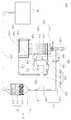
도 1은 본 발명의 일 실시예에 따른 하이브리드 악취탈취장치를 나타낸 단면도,
도 2는 도 1에서 제 1 밸브만 개방된 상태에서 물의 흐름을 나타낸 유체흐름도,
도 3은 도 1에서 제 2 밸브만 개방된 상태에서 물의 흐름을 나타낸 유체흐름도, 및
도 4는 도 1에서 제 1 밸브와 제 2 밸브가 개방된 상태에서 물의 흐름을 나타낸 유체흐름도이다.1 is a cross-sectional view of a hybrid odor removal device according to an embodiment of the present invention,
Fig. 2 is a fluid flow diagram showing the flow of water in the state in which only the first valve is opened in Fig. 1,
Figure 3 is a fluid flow diagram showing the flow of water in the state in which only the second valve is opened in Figure 1, and
FIG. 4 is a fluid flow diagram illustrating the flow of water with the first and second valves open in FIG. 1; FIG.
본 발명의 하이브리드 악취탈취장치를 이루는 구성요소들은 필요에 따라 일체형으로 사용되거나 각각 분리되어 사용될 수 있다. 또한, 사용 형태에 따라 일부 구성요소를 생략하여 사용 가능하다.The components constituting the hybrid malodor deodorization apparatus of the present invention may be used integrally or individually. In addition, some components may be omitted depending on the usage form.
본 발명에 따른 하이브리드 악취탈취장치(100)의 바람직한 실시 예를 도 1 내지 도 4를 참조하여 설명한다. 이 과정에서 도면에 도시된 선들의 두께나 구성요소의 크기 등은 설명의 명료성과 편의상 과장되게 도시되어 있을 수 있다. 또한, 후술되는 용어들은 본 발명에서의 기능을 고려하여 정의된 용어들로서 이는 사용자, 운용자의 의도 또는 관례에 따라 달라질 수 있다. 그러므로 이러한 용어들에 대한 정의는 본 명세서 전반에 걸친 내용을 토대로 기술되어야 할 것이다.
A preferred embodiment of the hybrid
1.One.하이브리드hybrid 악취탈취장치(100) The malodor-
이하, 도 1을 참조하여 본 발명의 일 실시예에 따른 하이브리드 악취탈취장치(100)를 설명하면 다음과 같다.Hereinafter, a hybrid
본 발명의 일 실시예에 따른 하이브리드 악취탈취장치(100)은 처리조(105)에서 유입된 공기 중 악취가 1차적으로 탈취되는 건식탈취모듈(110), 건식탈취모듈(110)로부터 탈취된 악취가 2차적으로 탈취되는 습식탈취모듈(120), 건식탈취모듈(110) 및 습식탈취모듈(120)과 연통하는 유로모듈(130), 습식탈취모듈(120)의 하부와 연통하는 산화모듈(140), 제 1 순환관(136)과 제 3 순환관(138) 사이에 배치되는 분사펌프(150), 유로모듈(130)의 개폐를 위한 밸브모듈(160) 및 건식탈취모듈(110)에서 정화된 공기를 습식탈취모듈(120)로 유도하거나 습식탈취모듈(120)에서 탈취되어 정화된 공기를 외부로 배출하기 위한 흡배기모듈(170)을 포함한다.The hybrid
건식탈취모듈(110)은 건식챔버(111), 건식탈취층(112), 제 1 건식탈취층(113), 제 2 건식탈취층(114) 및 제 3 건식탈취층(115)을 포함한다.The
건식챔버(111)는 양측이 개방된 중공형상으로 이루어지며, 건식챔버(111)의 일측은 유입관(131)과 연통하며, 그 타측은 제 1 분배관(133)과 연통한다. 이러한 건식챔버(111)의 내부에는 그 하부로부터 제 1 건식탈취층(113), 제 2 건식탈취층(114), 제 3 건식탈취층(115)이 순차적으로 적층됨에 따라 처리조(105)에서 생성된 악취를 포함하는 공기가 유입관(131)을 통해 유입되어 악취가 1차적으로 탈취되어 정화된다.One side of the
건식탈취층(112)은 제 1 건식탈취층(113), 제 2 건식탈취층(114), 및 제 3 건식탈취층(115)을 포함한다.The
제 1 건식탈취층(113)은 건식탈취를 위해 건식챔버(111)의 하부에 위치하며, 제올라이트 실리카겔인 것이 바람직하다.The first
제 2 건식탈취층(114)은 제 1 건식탈취층(113)의 상부에 적층되며, 소나무껍질인 것이 바람직하다.The second
제 3 건식탈취층(115)은 제 2 건식탈취층(114)의 상부에 적층되며, 활성탄 왕겨숯인 것이 바람직하다.
The third
습식탈취모듈(120)은 습식챔버(121), 습식탈취층(122), 제 1 습식탈취층(123), 제 2 습식탈취층(124) 및 제 3 습식탈취층(125)을 포함한다.The
습식챔버(121)는 내부가 빈 중공형상이고, 습식챔버(121)의 내부에는 그 상부로부터 제 1 습식탈취층(123), 제 2 습식탈취층(124)의 순서대로 적층되며, 제 3 습식탈취층(125)은 제 2 습식탈취층(124)과 이격되어 습식챔버(121)에 적층된다.The inside of the
또한, 제 2 습식탈취층(124)와 제 3 습식탈취층(125) 사이의 공간에 위치한 습식챔버(121)의 일측은 제 1 분배관(133)과 연통하며, 습식챔버(121)의 상부 일측으로는 제 1 순환관(136)이 삽입되어 위치한다.One side of the
아울러, 습식챔버(121)의 하부는 저수조(141)과 연통하며, 이러한 습식챔버(121)는 건식챔버(111)에서 1차적으로 악취가 탈취된 공기가 유입됨으로써 악취를 2차적으로 탈취한다.The lower part of the
습식탈취층(122)은 제 1 습식탈취층(123), 제 2 습식탈취층(124) 및 제 3 습식탈취층(125)을 포함한다.The
제 1 습식탈취층(123)은 습식챔버(121)의 상부에 위치하며, 실리카겔인 것이 바람직하다.The first
제 2 습식탈취층(124)은 제 1 습식탈취층(123)의 하부에 위치하며, 황산화철인 것이 바람직하다.The second
제 3 습식탈취층(125)은 제 2 습식탈취층(124)의 하부에 위치하며, 참나무 숯인 것이 바람직하다.
The third
유로모듈(130)은 유입관(131), 분배관(132), 순환관(135), 및 배출관(139)을 포함한다.The
유입관(131)은 처리조(105)와 건식탈취모듈(110)을 연통시키는 관이며, 이러한 유입관(131)은 처리조(105)로부터 유입되는 악취를 포함하는 공기가 건식챔버(111)로 유입되는 통로의 역할을 한다.The
분배관(132)은 제 1 분배관(133) 및 제 2 분배관(134)을 포함한다.The
제 1 분배관(133)은 건식탈취모듈(110)과 습식탈취모듈(120)의 일측을 연통시킨다.The
보다 구체적으로 제 1 분배관(133)의 일측은 건식챔버(111)의 상부와 연통하고, 제 1 분배관(133)의 타측은 제 2 습식탈취층(124)과 제 3 습식탈취층(125) 사이의 공간에 위치한 습식챔버(121)의 일측과 연통한다.More specifically, one side of the
또한, 제 1 분배관(133) 상에는 악취를 포함하는 공기를 유입시키기 위한 흡기팬(171)이 장착된다.An
아울러, 제 1 순환관(136)과 접하는 제 1 분배관(133)의 일부는 밴츄리관으로 형성되어 유속을 빠르게 한다.In addition, a portion of the
제 2 분배관(134)은 건식탈취모듈(110)과 배출관(139)의 일측을 연통시킨다.The
보다 구체적으로 제 2 분배관(134)의 일측은 건식챔버(111)의 상부, 및 제 1 분배관(133)과 연통하며, 그 타측은 배출관(139)과 연통한다.More specifically, one side of the
순환관(135)은 제 1 순환관(136), 제 2 순환관(137) 및 제 3 순환관(138)을 포함한다.The
제 1 순환관(136)은 습식탈취모듈(120)의 일측 상부와 연통한다. 보다 구체적으로 제 1 순환관(136)의 일부는 습식챔버(121)의 상부 일측부로는 삽입되어 습식챔버(121)의 하부로 물을 분사한다. 이를 위해 제 1 순환관(136)의 일측부에는 물을 분사하기 위한 다수의 홀이 형성될 수 있다.The first circulation pipe (136) communicates with the upper part of one side of the wet deodorization module (120). Particularly, a part of the
또한, 제 1 순환관(136)의 타측은 분사펌프(150)과 연결되어 분사펌프(150)에서 공급되는 물이 유입된다.The other side of the
제 2 순환관(137)은 제 1 순환관(136)과 제 1 분배관(133)을 연통시킨다.The second circulation pipe (137) communicates the first circulation pipe (136) and the first distribution pipe (133).
특히, 제 2 순환관(137)의 일측은 제 1 분배관(133)의 일부에 형성되는 벤츄리관에 삽입되어 물을 분사한다.Particularly, one side of the
제 3 순환관(138)은 제 2 순환관(137)과 저수조(141)를 연통시킨다.The
보다 구체적으로 제 3 순환관(138)의 일측은 분사펌프(150)와 연통함에 따라 제 2 순환관(137)과 연통하며, 그 타측은 저수조(141)와 연통하여 물을 순환시킨다.More specifically, one side of the
배출관(139)은 건식탈취모듈(110)로부터 유입된 공기 중 악취가 2차적으로 탈취되어 정화된 공기가 외부로 배출되도록 습식탈취모듈(120)의 상부와 연통한다.
The
산화모듈(140)은 저수조(141), 자외선 소독기(142) 및 수위계(143)를 포함한다.The
저수조(141)는 물을 수용하기 위한 저장탱크로서, 습식챔버(121)의 하부에 연통하도록 위치하며, 그 일측은 제 3 순환관(138)과 연통한다. 이때, 저수조(141)에 있는 물에 함유된 물질은 차아염소산소다 희석액인 것이 바람직하다.The
자외선 소독기(142)는 저수조(141)의 내측 하부에 위치하여 자외선을 조사하며, 자외선 소독기(142)의 동작에 의해 저수조(141) 내부의 물이 소독된다.The
또한, 자외선 소독기(142)는 동절기에 기온 저하로 인해 저수조(141) 내부에서 발생할 수 있는 동파나 기계의 오작동으로 인한 안전사고를 예방할 수 있다.In addition, the
수위계(143)는 저수조(141)의 내부에 위치하여 저수조(141) 내부의 수위를 감지한다.
The
분사펌프(150)는 저수조(141)로부터 유입되어 제 3 순환관(138)을 통과한 물을 제 1 순환관(136)으로 공급한다.
The
밸브모듈(160)은 제 1 밸브(161) 및 제 2 밸브(162)를 포함한다.The
제 1 밸브(161)는 제 2 분배관((134) 상에 장착되어 제어부에 의해 개폐 가능하다.The first valve (161) is mounted on the second distribution pipe (134) and is openable and closable by a control unit.
제 2 밸브(162)는 배출관(139) 상에 장착되어 제어부에 의해 개폐 가능하다.The
전술한 제 1 밸브(161) 및 제 2 밸브(162)는 제어부의 제어에 따라 처리조(105)로부터 유입되는 악취를 포함하는 공기의 흐름을 변경시켜 건식탈취모드 또는 습식탈취모드를 지원한다.
The
흡배기모듈(170)은 흡기팬(171) 및 배기팬(172)을 포함한다.The intake and
흡기팬(171)은 제 1 분배관(133) 상에 배치되며, 이러한 흡기팬(171)이 동작하는 경우 건식탈취모듈(110)을 거치면서 1차적으로 악취가 탈취된 공기를 제 1 분배관(133)으로 유입시킨다.The
배기팬(172)은 습식챔버(121)에 대향하는 배출관(139)의 일측에 배치되며, 이러한 배기팬(172)이 동작하는 경우 건식탈취모듈(110) 또는 습식탈취모듈(120)에서 악취가 탈취된 공기를 외부로 배출시킨다.
The
또한, 본 발명은 밸브모듈(160), 흡배기모듈(170), 분사펌프(150) 및 자외선 소독기(142)의 동작을 제어하는 제어부(미도시)를 더 포함한다.The present invention further includes a control unit (not shown) for controlling the operation of the
가령, 제어부에 의해 제 1 밸브(161)가 폐쇄되고 제 2 밸브(162)가 개방되는 경우, 제어부는 흡기팬(171)을 동작시킴에 따라 건식탈취모듈(110)에서 탈취된 악취가 제 1 분배관(133)을 따라 습식탈취모듈(120)로 유입될 수 있도록 제어하며, 분사펌프(150)를 동작시켜 제 1 순환관(136)과 제 2 순환관(137)을 통과한 물을 습식탈취모듈(120)로 유입시킴으로써 건식탈취모듈(110)에서 1차적으로 악취가 탈취된 공기를 습식으로 탈취시킨다.For example, when the
한편, 제어부에 의해 제 1 밸브(161)가 개방되고 제 2 밸브(162)가 폐쇄되는 경우, 제어부는 배기팬을 동작시켜 건식탈취모듈(110)에서 악취가 탈취된 후 정화된 공기로 여과하여 배출관(139)으로 배출될 수 있도록 제어한다.
Meanwhile, when the
2.2.하이브리드hybrid 악취탈취장치의 Odor removal device모드별By mode 작동방법 How it works
2-1.2-1.건식탈취모드Dry deodorization mode
이하, 도 2를 참고하여 건식탈취모드에 대해 설명한다.Hereinafter, the dry deodorization mode will be described with reference to Fig.
제어부에 의해 제 1 밸브(161)가 개방되고, 제 2 밸브(162)가 폐쇄된다.The
다음, 제어부에 의해 배기팬(172)이 동작하면, 처리조(105)에서 생성된 악취를 포함하는 공기가 유입관(131)을 따라 건식챔버(111)로 유입되고, 악취를 포함하는 공기가 제 1 건식탈취층(113), 제 2 건식탈취층(114) 및 제 3 건식탈취층(115)을 순서대로 통과하는 과정에서 악취가 1차적으로 탈취된다(A).Next, when the
다음, 1차적으로 악취가 탈취된 공기는 제 2 분배관(134)을 따라 유입되어 배출관(139)을 통해 외부로 배출된다(A).
Next, the air, which is primarily deodorized, flows along the
2-2. 복합탈취모드(2-2. Multiple deodorization mode (건식탈취모드와With dry deodorization mode습식탈취모드)Wet deodorization mode)
이하, 도 3을 참고하여 건식탈취모드와 습식탈취모드가 동시에 동작하는 것을 설명한다.Hereinafter, the simultaneous operation of the dry deodorization mode and the wet deodorization mode will be described with reference to FIG.
제어부에 의해 제 1 밸브(161)가 폐쇄되고, 제 2 밸브(162)가 개방된다.The
다음, 제어부에 의해 흡기팬(171)이 동작하면, 처리조(105)에서 생성된 악취를 포함하는 공기가 유입관(131)을 따라 건식챔버(111)로 유입되고, 악취를 포함하는 공기가 제 1 건식탈취층(113), 제 2 건식탈취층(114) 및 제 3 건식탈취층(115)을 순서대로 통과하는 과정에서 악취가 1차적으로 탈취된다(A).Next, when the
다음, 흡기팬(171)에 의해 1차적으로 악취가 탈취된 공기가 제 1 분배관(133)으로 유입되면, 제어부에 의해 분사펌프(150)가 동작한다(B).Next, when the air, which is initially stinked by the
이때, 저수조(141) 내부의 물은 제 3 순환관(138)을 따라 제 1 순환관(136)으로 흐른 후 다수의 홀이 형성된 제 1 순환관(136)의 일측부에서 습식챔버(121)의 하부로 분사된다(B).At this time, the water in the
이와 동시에 분사펌프(150)에 의해 공급되는 물은 제 2 순환관(137)로 유입되어 제 1 순환관(136)과 접하는 제 1 분배관(133)의 일부에 형성된 밴츄리관으로 분사된다(B). 이때, 물은 제 1 분배관(133)에 의해 밴츄리관으로 유입되는 공기에 분사되고, 물이 분사된 상태의 공기가 습식챔버(121)로 유입된다(B).At the same time, the water supplied by the
이후, 공기는 제 3 습식탈취층(125), 제 2 습식탈취층(124), 제 3 습식탈취층(123)을 통과하면서 제 1 순환관(136)의 일측부로부터 분사되는 물에 의해 2차적으로 탈취되며, 정화된 공기가 배출관(139)을 통하여 외부로 배출된다(A).
Thereafter, the air is passed through the third
한편, 도 4에 도시된 바와 같이 제 1 밸브(161)과 제 2 밸브(162)가 동시에 개방된 경우에도 건식탈취모드와 습식탈취모드가 가능하며, 물의 순환은 전술한 건식탈취모드와 복합탈취모드를 합친 것과 동일하다.
4, the dry deodorization mode and the wet deodorization mode are possible even when the
상기에서는 본 발명의 바람직한 실시예를 참조하여 설명하였지만, 당업계에서 통상의 지식을 가진 자라면 이하의 특허 청구범위에 기재된 본 발명의 사상 및 영역을 벗어나지 않는 범위 내에서 본 발명을 다양하게 수정 및 변경시킬 수 있음을 이해할 수 있을 것이다.
It will be apparent to those skilled in the art that various modifications and variations can be made in the present invention without departing from the spirit or scope of the invention as defined in the appended claims. It will be understood that the present invention can be changed.
100 : 하이브리드 악취탈취장치
105 : 처리조
110 : 건식탈취모듈
111 : 건식챔버
112 : 건식탈취층
113 : 제 1 건식탈취층
114 : 제 2 건식탈취층
114 : 제 3 건식탈취층
120 : 습식탈취모듈
121 : 습식챔버
122 : 습식탈취층
123 : 제 1 습식탈취층
124 : 제 2 습식탈취층
125 : 제 3 습식탈취층
130 : 유로모듈
131 : 유입관
132 : 분배관
133 : 제 1 분배관
134 : 제 2 분배관
135 : 순환관
136 : 제 1 순환관
137 : 제 2 순환관
138 : 제 3 순환관
139 : 배출관
140 : 산화모듈
141 : 저수조
142 : 자외선 소독기
143 : 수위계
150 : 분사펌프
160 : 밸브모듈
161 : 제 1 밸브
162 : 제 2 밸브
170 : 흡배기모듈
171 : 흡기팬
172 : 배기팬100: Hybrid odor deodorization device
105: Treatment tank
110: Dry deodorization module
111: Drying chamber
112: Dry deodorization layer
113: First dry deodorization layer
114: Second dry deodorization layer
114: Third dry deodorization layer
120: Wet deodorization module
121: Wet chamber
122: wet deodorization layer
123: 1st wet deodorization layer
124: Second wet deodorization layer
125: Third wet deodorization layer
130: Euro module
131: inlet pipe
132: Minute piping
133: 1 st piping
134: Second piping
135: Circulation tube
136: First circulation pipe
137: Second circulation pipe
138: Third circulation pipe
139: discharge pipe
140: oxidation module
141: Water tank
142: Ultraviolet sterilizer
143: Water gauge
150: injection pump
160: Valve module
161: first valve
162: second valve
170: Intake and Exhaust Module
171: Intake fan
172: exhaust fan
Claims (10)
Translated fromKorean상기 건식탈취모듈로부터 탈취된 악취가 2차적으로 탈취되는 습식탈취모듈;을 포함하는 것을 특징으로 하는,
하이브리드 악취탈취장치.
A dry deodorization module in which odor is primarily deodorized in the air introduced from the treatment tank; And
And a wet deodorization module in which the odor deodorized from the dry deodorization module is secondarily deodorized.
Hybrid odor deodorization device.
상기 하이브리드 탈취장치는,
상기 처리조와 상기 건식탈취모듈을 연통시키는 유입관;
상기 건식탈취모듈로부터 상기 악취가 2차적으로 탈취되어 정화된 공기가 외부로 배출되도록 상기 습식탈취모듈의 상부와 연통하는 배출관;
상기 건식탈취모듈과 상기 습식탈취모듈의 일측을 연통시키는 제 1 분배관 및 상기 건식탈취모듈과 상기 배출관의 일측을 연통시키는 제 2 분배관으로 이루어진 분배관;으로 이루어진 유로모듈;을 포함하고,
상기 제 2 분배관에는 개폐 가능한 제 1 밸브가 형성되며,
상기 배출관에는 개폐 가능한 제 2 밸브가 형성되는 것을 특징으로 하는,
하이브리드 악취탈취장치.The method according to claim 1,
The hybrid deodorization apparatus includes:
An inlet pipe communicating the treatment tank and the dry deodorization module;
A discharge pipe communicating with the upper portion of the wet deodorization module so that the air from which the odor is secondarily deodorized from the dry deodorization module and the purified air is discharged to the outside;
And a distribution pipe formed of a first distribution pipe communicating the dry deodorization module and one side of the wet deodorization module and a second distribution pipe communicating the dry deodorization module and one side of the discharge pipe,
A first valve capable of opening and closing is formed in the second distribution pipe,
Characterized in that the discharge pipe is provided with a second valve capable of opening and closing,
Hybrid odor deodorization device.
상기 하이브리드 탈취장치는 상기 습식탈취모듈의 하부와 연통하는 산화모듈;을 더 포함하고,
상기 산화모듈은,
저수조;
상기 저수조의 내측 하부에 위치하여 자외선을 조사하는 자외선 소독기; 및
상기 저수조의 내부에 위치하여 상기 저수조 내부의 수위를 감지하는 수위계;를 포함하는 것을 특징으로 하는,
하이브리드 악취탈취장치.
3. The method of claim 2,
Wherein the hybrid deodorization apparatus further comprises an oxidation module in communication with a lower portion of the wet deodorization module,
The oxidation module comprises:
Water tank;
An ultraviolet sterilizer located in an inner lower portion of the water storage tank for irradiating ultraviolet rays; And
And a water level gauge which is located inside the water storage tank and senses the water level inside the water storage tank.
Hybrid odor deodorization device.
상기 유로모듈은,
상기 습식탈취모듈의 일측 상부와 연통하는 제 1 순환관;
상기 제 1 순환관과 상기 제 1 분배관을 연통시기는 제 2 순환관; 및
상기 제 2 순환관과 상기 저수조를 연통시키는 제 3 순환관;을 포함하는 순환관;을 더 포함하는 것을 특징으로 하는,
하이브리드 악취탈취장치.
The method of claim 3,
The flow-
A first circulation pipe communicating with one upper side of the wet deodorization module;
Wherein the communication timing between the first circulation pipe and the first distribution pipe is a second circulation pipe; And
And a third circulation pipe communicating the second circulation pipe and the water storage tank.
Hybrid odor deodorization device.
상기 하이브리드 탈취장치는, 상기 제 1 분배관 상에 배치되는 흡기팬 및 상기 배출관 상에 배치되는 배기팬으로 구성된 흡배기모듈;을 더 포함하는 것을 특징으로 하는,
하이브리드 악취탈취장치.
5. The method of claim 4,
Wherein the hybrid deodorization apparatus further comprises an intake and exhaust module including an intake fan disposed on the first distribution pipe and an exhaust fan disposed on the discharge pipe,
Hybrid odor deodorization device.
상기 하이브리드 탈취장치는 상기 제 1 순환관과 상기 제 3 순환관 사이에 배치되는 분사펌프;를 더 포함하고,
상기 분사펌프는 상기 저수조로부터 유입되어 상기 제 3 순환관을 통과한 물을 상기 제 1 순환관으로 공급하는 것을 특징으로 하는,
하이브리드 악취탈취장치.
6. The method of claim 5,
Wherein the hybrid deodorization apparatus further comprises an injection pump disposed between the first circulation pipe and the third circulation pipe,
Wherein the injection pump supplies water, which has flowed from the water storage tank, through the third circulation pipe to the first circulation pipe,
Hybrid odor deodorization device.
상기 하이브리드 탈취장치는, 상기 밸브, 상기 흡배기모듈, 상기 분사펌프 및 상기 자외선 소독기의 동작을 제어하는 제어부;를 더 포함하는 것을 특징으로 하는,
하이브리드 악취탈취장치.
The method according to claim 6,
Wherein the hybrid deodorization apparatus further comprises a controller for controlling operations of the valve, the intake and exhaust module, the injection pump, and the ultraviolet light sterilizer.
Hybrid odor deodorization device.
상기 제 1 순환관과 접하는 상기 제 1 분배관의 일부는 밴츄리관인 것을 특징으로 하는,
하이브리드 악취탈취장치.
8. The method of claim 7,
Wherein a part of the first distribution pipe in contact with the first circulation pipe is a venturi pipe.
Hybrid odor deodorization device.
상기 제 1 밸브가 폐쇄되고 상기 제 2 밸브가 개방되는 경우,
상기 제어부는 상기 흡기팬을 동작시킴에 따라 상기 건식탈취모듈에서 탈취된 악취가 상기 제 1 분배관을 따라 상기 습식탈취모듈로 유입되도록 제어하며,
상기 분사펌프를 동작시켜 상기 제 1 순환관과 상기 제 2 순환관을 통과한 상기 물을 상기 습식탈취모듈로 유입시킴으로써 상기 건식탈취모듈에서 탈취된 악취를 습식으로 탈취시키는 것을 특징으로 하는,
하이브리드 악취탈취장치.
9. The method according to any one of claims 1 to 8,
When the first valve is closed and the second valve is opened,
The control unit controls the malodor taken from the dry deodorization module to flow into the wet deodorization module along the first distribution pipe as the intake fan is operated,
And the water is passed through the first circulation pipe and the second circulation pipe to the wet deodorization module by operating the injection pump to wet off the odor deodorized from the dry deodorization module.
Hybrid odor deodorization device.
상기 제 1 밸브가 개방되고 상기 제 2 밸브가 폐쇄되는 경우,
상기 제어부는 배기팬을 동작시켜 상기 건식탈취모듈에서 상기 악취가 탈취된 후 정화된 공기로 여과하여 상기 배출관으로 배출될 수 있도록 제어하는 것을 특징으로 하는,
하이브리드 악취탈취장치.9. The method according to any one of claims 1 to 8,
When the first valve is open and the second valve is closed,
Wherein the control unit operates the exhaust fan to filter the odor in the dry deodorization module with the purified air after being deodorized and to discharge the purified air to the discharge pipe.
Hybrid odor deodorization device.
Priority Applications (1)
| Application Number | Priority Date | Filing Date | Title |
|---|---|---|---|
| KR1020140054549AKR20150127964A (en) | 2014-05-08 | 2014-05-08 | A hybrid deodorizing device |
Applications Claiming Priority (1)
| Application Number | Priority Date | Filing Date | Title |
|---|---|---|---|
| KR1020140054549AKR20150127964A (en) | 2014-05-08 | 2014-05-08 | A hybrid deodorizing device |
Publications (1)
| Publication Number | Publication Date |
|---|---|
| KR20150127964Atrue KR20150127964A (en) | 2015-11-18 |
Family
ID=54838653
Family Applications (1)
| Application Number | Title | Priority Date | Filing Date |
|---|---|---|---|
| KR1020140054549ACeasedKR20150127964A (en) | 2014-05-08 | 2014-05-08 | A hybrid deodorizing device |
Country Status (1)
| Country | Link |
|---|---|
| KR (1) | KR20150127964A (en) |
Cited By (3)
| Publication number | Priority date | Publication date | Assignee | Title |
|---|---|---|---|---|
| KR101872411B1 (en)* | 2017-12-05 | 2018-06-29 | (주)에스에스에코텍 | Deodorizing system |
| KR102083665B1 (en)* | 2019-08-22 | 2020-03-03 | (주)제이엔텍 | Sterilization and Deodorization System of Cattle Pen |
| KR102224430B1 (en)* | 2019-09-17 | 2021-03-08 | 주식회사 에코노바 | Swivel Flow Type Chemical Cleaning Deodorizer |
- 2014
- 2014-05-08KRKR1020140054549Apatent/KR20150127964A/ennot_activeCeased
Cited By (3)
| Publication number | Priority date | Publication date | Assignee | Title |
|---|---|---|---|---|
| KR101872411B1 (en)* | 2017-12-05 | 2018-06-29 | (주)에스에스에코텍 | Deodorizing system |
| KR102083665B1 (en)* | 2019-08-22 | 2020-03-03 | (주)제이엔텍 | Sterilization and Deodorization System of Cattle Pen |
| KR102224430B1 (en)* | 2019-09-17 | 2021-03-08 | 주식회사 에코노바 | Swivel Flow Type Chemical Cleaning Deodorizer |
Similar Documents
| Publication | Publication Date | Title |
|---|---|---|
| KR101734185B1 (en) | System for removing foul smell of multiple pollutant with variable laminated absorption type, and deodorization method using the same | |
| KR100860077B1 (en) | Inorganic and Organic Odor Deodorizer | |
| KR100986245B1 (en) | Apparatus and method of high efficiency chemical cleaning-type deodorization using non-motorized mixing feeder | |
| KR101591849B1 (en) | Washer type deodorizing apparatus | |
| KR101183665B1 (en) | Malodor gas of animal-excretion removing method | |
| KR20180031211A (en) | Odor using odor materials by aerobic microorganisms useful to feed swine and remove the system | |
| JP2008036513A (en) | Gas processing unit and gas processing system | |
| KR20140068537A (en) | Air purifier with function of sterilization and deodorization | |
| KR20150127964A (en) | A hybrid deodorizing device | |
| KR101738349B1 (en) | odor treatment apparatus | |
| KR102017000B1 (en) | Disinfectant supply system for Tower of chemical cleaning | |
| KR100984387B1 (en) | Compact typed apparatus capable of removing malodor gas of animal-excretion | |
| KR100936440B1 (en) | The bad smell deodorization method and the deodorizing device using a biofilter | |
| KR101303335B1 (en) | Deodorization tower using ozone and ozone sterilization water | |
| KR101450603B1 (en) | Ammonia Gas Reduction Device Using Ozonized Water | |
| KR100736438B1 (en) | Odor Diffusion Prevention Device for Water Treatment Facilities | |
| KR20170063013A (en) | Deodorization Module Using Clean Water | |
| JP2005013789A (en) | Air cleaner | |
| KR100834308B1 (en) | Rotary Biofilter Deodorizer | |
| CN210473600U (en) | Gas purification and deodorization device | |
| KR101939746B1 (en) | Charcoal filter regeneration system and it using charcoal filter regeneration method | |
| KR20010107882A (en) | The drawer multi-step style Biofilter with Cast and woodchip | |
| KR101473995B1 (en) | odor treatment apparatus using tall tree by-product | |
| KR20170063020A (en) | Method Of Deodorizing for Air | |
| KR100843344B1 (en) | Odor deodorization method using bio filter |
Legal Events
| Date | Code | Title | Description |
|---|---|---|---|
| PA0109 | Patent application | Patent event code:PA01091R01D Comment text:Patent Application Patent event date:20140508 | |
| PA0201 | Request for examination | ||
| PA0302 | Request for accelerated examination | Patent event date:20140516 Patent event code:PA03022R01D Comment text:Request for Accelerated Examination Patent event date:20140508 Patent event code:PA03021R01I Comment text:Patent Application | |
| PE0902 | Notice of grounds for rejection | Comment text:Notification of reason for refusal Patent event date:20140807 Patent event code:PE09021S01D | |
| PE0601 | Decision on rejection of patent | Patent event date:20141120 Comment text:Decision to Refuse Application Patent event code:PE06012S01D Patent event date:20140807 Comment text:Notification of reason for refusal Patent event code:PE06011S01I | |
| PJ0201 | Trial against decision of rejection | Patent event date:20150120 Comment text:Request for Trial against Decision on Refusal Patent event code:PJ02012R01D Patent event date:20141120 Comment text:Decision to Refuse Application Patent event code:PJ02011S01I Appeal kind category:Appeal against decision to decline refusal Decision date:20151123 Appeal identifier:2015101000249 Request date:20150120 | |
| PG1501 | Laying open of application | ||
| J301 | Trial decision | Free format text:TRIAL DECISION FOR APPEAL AGAINST DECISION TO DECLINE REFUSAL REQUESTED 20150120 Effective date:20151123 | |
| PJ1301 | Trial decision | Patent event code:PJ13011S01D Patent event date:20151124 Comment text:Trial Decision on Objection to Decision on Refusal Appeal kind category:Appeal against decision to decline refusal Request date:20150120 Decision date:20151123 Appeal identifier:2015101000249 |