KR20150127160A - Microprojection applicators - Google Patents
Microprojection applicatorsDownload PDFInfo
- Publication number
- KR20150127160A KR20150127160AKR1020157027531AKR20157027531AKR20150127160AKR 20150127160 AKR20150127160 AKR 20150127160AKR 1020157027531 AKR1020157027531 AKR 1020157027531AKR 20157027531 AKR20157027531 AKR 20157027531AKR 20150127160 AKR20150127160 AKR 20150127160A
- Authority
- KR
- South Korea
- Prior art keywords
- plunger
- skin
- distal end
- microprojection
- energy
- Prior art date
- Legal status (The legal status is an assumption and is not a legal conclusion. Google has not performed a legal analysis and makes no representation as to the accuracy of the status listed.)
- Granted
Links
- 230000000903blocking effectEffects0.000claimsabstractdescription102
- 238000005452bendingMethods0.000claimsabstractdescription59
- 238000004146energy storageMethods0.000claimsabstractdescription58
- 238000000034methodMethods0.000claimsdescription103
- 239000003814drugSubstances0.000claimsdescription65
- 239000000463materialSubstances0.000claimsdescription38
- 229940124597therapeutic agentDrugs0.000claimsdescription37
- 239000000853adhesiveSubstances0.000claimsdescription34
- 230000001070adhesive effectEffects0.000claimsdescription34
- 230000003014reinforcing effectEffects0.000claimsdescription32
- 230000000717retained effectEffects0.000claimsdescription26
- 239000012790adhesive layerSubstances0.000claimsdescription24
- 229910052751metalInorganic materials0.000claimsdescription24
- 239000002184metalSubstances0.000claimsdescription24
- 229940079593drugDrugs0.000claimsdescription21
- 238000006073displacement reactionMethods0.000claimsdescription16
- 229960005486vaccineDrugs0.000claimsdescription15
- 230000004888barrier functionEffects0.000claimsdescription14
- 102000004169proteins and genesHuman genes0.000claimsdescription14
- 108090000623proteins and genesProteins0.000claimsdescription14
- 108090000765processed proteins & peptidesProteins0.000claimsdescription13
- 239000010410layerSubstances0.000claimsdescription12
- 229910045601alloyInorganic materials0.000claimsdescription10
- 239000000956alloySubstances0.000claimsdescription10
- 239000010935stainless steelSubstances0.000claimsdescription10
- 229910001220stainless steelInorganic materials0.000claimsdescription10
- 229910000975Carbon steelInorganic materials0.000claimsdescription9
- RTAQQCXQSZGOHL-UHFFFAOYSA-NTitaniumChemical compound[Ti]RTAQQCXQSZGOHL-UHFFFAOYSA-N0.000claimsdescription9
- 239000010962carbon steelSubstances0.000claimsdescription9
- 230000033001locomotionEffects0.000claimsdescription9
- 239000010936titaniumSubstances0.000claimsdescription9
- 229910052719titaniumInorganic materials0.000claimsdescription9
- 230000006835compressionEffects0.000claimsdescription8
- 238000007906compressionMethods0.000claimsdescription8
- 150000003384small moleculesChemical class0.000claimsdescription8
- 210000003491skinAnatomy0.000description123
- 238000003491arrayMethods0.000description17
- 239000013543active substanceSubstances0.000description9
- 239000012528membraneSubstances0.000description9
- 230000000670limiting effectEffects0.000description8
- 206010057190Respiratory tract infectionsDiseases0.000description7
- 230000008901benefitEffects0.000description7
- 239000003795chemical substances by applicationSubstances0.000description6
- 238000013461designMethods0.000description6
- 230000002787reinforcementEffects0.000description6
- 210000001519tissueAnatomy0.000description6
- 230000000694effectsEffects0.000description5
- 238000004519manufacturing processMethods0.000description5
- 229920000642polymerPolymers0.000description5
- -1but not limited toSubstances0.000description4
- 108091034117OligonucleotideProteins0.000description3
- 206010043376TetanusDiseases0.000description3
- JLCPHMBAVCMARE-UHFFFAOYSA-N[3-[[3-[[3-[[3-[[3-[[3-[[3-[[3-[[3-[[3-[[3-[[5-(2-amino-6-oxo-1H-purin-9-yl)-3-[[3-[[3-[[3-[[3-[[3-[[5-(2-amino-6-oxo-1H-purin-9-yl)-3-[[5-(2-amino-6-oxo-1H-purin-9-yl)-3-hydroxyoxolan-2-yl]methoxy-hydroxyphosphoryl]oxyoxolan-2-yl]methoxy-hydroxyphosphoryl]oxy-5-(5-methyl-2,4-dioxopyrimidin-1-yl)oxolan-2-yl]methoxy-hydroxyphosphoryl]oxy-5-(6-aminopurin-9-yl)oxolan-2-yl]methoxy-hydroxyphosphoryl]oxy-5-(6-aminopurin-9-yl)oxolan-2-yl]methoxy-hydroxyphosphoryl]oxy-5-(6-aminopurin-9-yl)oxolan-2-yl]methoxy-hydroxyphosphoryl]oxy-5-(6-aminopurin-9-yl)oxolan-2-yl]methoxy-hydroxyphosphoryl]oxyoxolan-2-yl]methoxy-hydroxyphosphoryl]oxy-5-(5-methyl-2,4-dioxopyrimidin-1-yl)oxolan-2-yl]methoxy-hydroxyphosphoryl]oxy-5-(4-amino-2-oxopyrimidin-1-yl)oxolan-2-yl]methoxy-hydroxyphosphoryl]oxy-5-(5-methyl-2,4-dioxopyrimidin-1-yl)oxolan-2-yl]methoxy-hydroxyphosphoryl]oxy-5-(5-methyl-2,4-dioxopyrimidin-1-yl)oxolan-2-yl]methoxy-hydroxyphosphoryl]oxy-5-(6-aminopurin-9-yl)oxolan-2-yl]methoxy-hydroxyphosphoryl]oxy-5-(6-aminopurin-9-yl)oxolan-2-yl]methoxy-hydroxyphosphoryl]oxy-5-(4-amino-2-oxopyrimidin-1-yl)oxolan-2-yl]methoxy-hydroxyphosphoryl]oxy-5-(4-amino-2-oxopyrimidin-1-yl)oxolan-2-yl]methoxy-hydroxyphosphoryl]oxy-5-(4-amino-2-oxopyrimidin-1-yl)oxolan-2-yl]methoxy-hydroxyphosphoryl]oxy-5-(6-aminopurin-9-yl)oxolan-2-yl]methoxy-hydroxyphosphoryl]oxy-5-(4-amino-2-oxopyrimidin-1-yl)oxolan-2-yl]methyl [5-(6-aminopurin-9-yl)-2-(hydroxymethyl)oxolan-3-yl] hydrogen phosphatePolymersCc1cn(C2CC(OP(O)(=O)OCC3OC(CC3OP(O)(=O)OCC3OC(CC3O)n3cnc4c3nc(N)[nH]c4=O)n3cnc4c3nc(N)[nH]c4=O)C(COP(O)(=O)OC3CC(OC3COP(O)(=O)OC3CC(OC3COP(O)(=O)OC3CC(OC3COP(O)(=O)OC3CC(OC3COP(O)(=O)OC3CC(OC3COP(O)(=O)OC3CC(OC3COP(O)(=O)OC3CC(OC3COP(O)(=O)OC3CC(OC3COP(O)(=O)OC3CC(OC3COP(O)(=O)OC3CC(OC3COP(O)(=O)OC3CC(OC3COP(O)(=O)OC3CC(OC3COP(O)(=O)OC3CC(OC3COP(O)(=O)OC3CC(OC3COP(O)(=O)OC3CC(OC3COP(O)(=O)OC3CC(OC3COP(O)(=O)OC3CC(OC3CO)n3cnc4c(N)ncnc34)n3ccc(N)nc3=O)n3cnc4c(N)ncnc34)n3ccc(N)nc3=O)n3ccc(N)nc3=O)n3ccc(N)nc3=O)n3cnc4c(N)ncnc34)n3cnc4c(N)ncnc34)n3cc(C)c(=O)[nH]c3=O)n3cc(C)c(=O)[nH]c3=O)n3ccc(N)nc3=O)n3cc(C)c(=O)[nH]c3=O)n3cnc4c3nc(N)[nH]c4=O)n3cnc4c(N)ncnc34)n3cnc4c(N)ncnc34)n3cnc4c(N)ncnc34)n3cnc4c(N)ncnc34)O2)c(=O)[nH]c1=OJLCPHMBAVCMARE-UHFFFAOYSA-N0.000description3
- 230000008859changeEffects0.000description3
- 206010013023diphtheriaDiseases0.000description3
- 230000007246mechanismEffects0.000description3
- 150000002739metalsChemical class0.000description3
- 230000004048modificationEffects0.000description3
- 238000012986modificationMethods0.000description3
- 230000035699permeabilityEffects0.000description3
- 238000003860storageMethods0.000description3
- 239000013589supplementSubstances0.000description3
- 230000001225therapeutic effectEffects0.000description3
- SFLSHLFXELFNJZ-QMMMGPOBSA-N(-)-norepinephrineChemical compoundNC[C@H](O)C1=CC=C(O)C(O)=C1SFLSHLFXELFNJZ-QMMMGPOBSA-N0.000description2
- RTQWWZBSTRGEAV-PKHIMPSTSA-N2-[[(2s)-2-[bis(carboxymethyl)amino]-3-[4-(methylcarbamoylamino)phenyl]propyl]-[2-[bis(carboxymethyl)amino]propyl]amino]acetic acidChemical compoundCNC(=O)NC1=CC=C(C[C@@H](CN(CC(C)N(CC(O)=O)CC(O)=O)CC(O)=O)N(CC(O)=O)CC(O)=O)C=C1RTQWWZBSTRGEAV-PKHIMPSTSA-N0.000description2
- 108700012941GNRH1Proteins0.000description2
- 239000000579Gonadotropin-Releasing HormoneSubstances0.000description2
- 108010000817LeuprolideProteins0.000description2
- 102000003982Parathyroid hormoneHuman genes0.000description2
- 108090000445Parathyroid hormoneProteins0.000description2
- 201000005702PertussisDiseases0.000description2
- 239000008186active pharmaceutical agentSubstances0.000description2
- 238000007792additionMethods0.000description2
- 230000000844anti-bacterial effectEffects0.000description2
- 229940121363anti-inflammatory agentDrugs0.000description2
- 239000002260anti-inflammatory agentSubstances0.000description2
- 229940125681anticonvulsant agentDrugs0.000description2
- 239000001961anticonvulsive agentSubstances0.000description2
- 239000003472antidiabetic agentSubstances0.000description2
- 239000002246antineoplastic agentSubstances0.000description2
- 210000004369bloodAnatomy0.000description2
- 239000008280bloodSubstances0.000description2
- 239000002327cardiovascular agentSubstances0.000description2
- 229940125692cardiovascular agentDrugs0.000description2
- 210000004207dermisAnatomy0.000description2
- 238000012377drug deliveryMethods0.000description2
- 229940088679drug related substanceDrugs0.000description2
- 239000012530fluidSubstances0.000description2
- 239000012634fragmentSubstances0.000description2
- 229960003297gemtuzumab ozogamicinDrugs0.000description2
- 229940088597hormoneDrugs0.000description2
- 239000005556hormoneSubstances0.000description2
- 229940084986human chorionic gonadotropinDrugs0.000description2
- 229960001001ibritumomab tiuxetanDrugs0.000description2
- NOESYZHRGYRDHS-UHFFFAOYSA-NinsulinChemical compoundN1C(=O)C(NC(=O)C(CCC(N)=O)NC(=O)C(CCC(O)=O)NC(=O)C(C(C)C)NC(=O)C(NC(=O)CN)C(C)CC)CSSCC(C(NC(CO)C(=O)NC(CC(C)C)C(=O)NC(CC=2C=CC(O)=CC=2)C(=O)NC(CCC(N)=O)C(=O)NC(CC(C)C)C(=O)NC(CCC(O)=O)C(=O)NC(CC(N)=O)C(=O)NC(CC=2C=CC(O)=CC=2)C(=O)NC(CSSCC(NC(=O)C(C(C)C)NC(=O)C(CC(C)C)NC(=O)C(CC=2C=CC(O)=CC=2)NC(=O)C(CC(C)C)NC(=O)C(C)NC(=O)C(CCC(O)=O)NC(=O)C(C(C)C)NC(=O)C(CC(C)C)NC(=O)C(CC=2NC=NC=2)NC(=O)C(CO)NC(=O)CNC2=O)C(=O)NCC(=O)NC(CCC(O)=O)C(=O)NC(CCCNC(N)=N)C(=O)NCC(=O)NC(CC=3C=CC=CC=3)C(=O)NC(CC=3C=CC=CC=3)C(=O)NC(CC=3C=CC(O)=CC=3)C(=O)NC(C(C)O)C(=O)N3C(CCC3)C(=O)NC(CCCCN)C(=O)NC(C)C(O)=O)C(=O)NC(CC(N)=O)C(O)=O)=O)NC(=O)C(C(C)CC)NC(=O)C(CO)NC(=O)C(C(C)O)NC(=O)C1CSSCC2NC(=O)C(CC(C)C)NC(=O)C(NC(=O)C(CCC(N)=O)NC(=O)C(CC(N)=O)NC(=O)C(NC(=O)C(N)CC=1C=CC=CC=1)C(C)C)CC1=CN=CN1NOESYZHRGYRDHS-UHFFFAOYSA-N0.000description2
- 230000001788irregularEffects0.000description2
- GFIJNRVAKGFPGQ-LIJARHBVSA-NleuprolideChemical compoundCCNC(=O)[C@@H]1CCCN1C(=O)[C@H](CCCNC(N)=N)NC(=O)[C@H](CC(C)C)NC(=O)[C@@H](CC(C)C)NC(=O)[C@@H](NC(=O)[C@H](CO)NC(=O)[C@H](CC=1C2=CC=CC=C2NC=1)NC(=O)[C@H](CC=1N=CNC=1)NC(=O)[C@H]1NC(=O)CC1)CC1=CC=C(O)C=C1GFIJNRVAKGFPGQ-LIJARHBVSA-N0.000description2
- 229960004338leuprorelinDrugs0.000description2
- 239000007788liquidSubstances0.000description2
- 210000000214mouthAnatomy0.000description2
- 229960002748norepinephrineDrugs0.000description2
- SFLSHLFXELFNJZ-UHFFFAOYSA-NnorepinephrineNatural productsNCC(O)C1=CC=C(O)C(O)=C1SFLSHLFXELFNJZ-UHFFFAOYSA-N0.000description2
- 239000000199parathyroid hormoneSubstances0.000description2
- 229960001319parathyroid hormoneDrugs0.000description2
- 230000037368penetrate the skinEffects0.000description2
- 230000035515penetrationEffects0.000description2
- 239000004033plasticSubstances0.000description2
- 229920003023plasticPolymers0.000description2
- 239000002861polymer materialSubstances0.000description2
- 230000008569processEffects0.000description2
- 229960004641rituximabDrugs0.000description2
- 201000005404rubellaDiseases0.000description2
- QZAYGJVTTNCVMB-UHFFFAOYSA-NserotoninChemical compoundC1=C(O)C=C2C(CCN)=CNC2=C1QZAYGJVTTNCVMB-UHFFFAOYSA-N0.000description2
- 231100000245skin permeabilityToxicity0.000description2
- 230000036558skin tensionEffects0.000description2
- 239000007787solidSubstances0.000description2
- 210000000434stratum corneumAnatomy0.000description2
- IMCGHZIGRANKHV-AJNGGQMLSA-Ntert-butyl (3s,5s)-2-oxo-5-[(2s,4s)-5-oxo-4-propan-2-yloxolan-2-yl]-3-propan-2-ylpyrrolidine-1-carboxylateChemical compoundO1C(=O)[C@H](C(C)C)C[C@H]1[C@H]1N(C(=O)OC(C)(C)C)C(=O)[C@H](C(C)C)C1IMCGHZIGRANKHV-AJNGGQMLSA-N0.000description2
- 238000012546transferMethods0.000description2
- SNICXCGAKADSCV-JTQLQIEISA-N(-)-NicotineChemical compoundCN1CCC[C@H]1C1=CC=CN=C1SNICXCGAKADSCV-JTQLQIEISA-N0.000description1
- YGGIRYYNWQICCP-LDRBRYNMSA-N(2s)-n-[(2s)-1-[[(2s)-1-[[(2s)-1-[[(2s)-1-[[(2r)-1-[[(2s)-1-[[(2s)-5-(diaminomethylideneamino)-1-[(2s)-2-(ethylcarbamoyl)pyrrolidin-1-yl]-1-oxopentan-2-yl]amino]-4-methyl-1-oxopentan-2-yl]-methylamino]-3-(1h-indol-3-yl)-1-oxopropan-2-yl]amino]-3-(4-hydroxChemical compoundCCNC(=O)[C@@H]1CCCN1C(=O)[C@H](CCCN=C(N)N)NC(=O)[C@H](CC(C)C)N(C)C(=O)[C@H](NC(=O)[C@H](CC=1C=CC(O)=CC=1)NC(=O)[C@H](CO)NC(=O)[C@H](CC=1C2=CC=CC=C2NC=1)NC(=O)[C@H](CC=1NC=NC=1)NC(=O)[C@H]1NC(=O)CC1)CC1=CNC2=CC=CC=C12YGGIRYYNWQICCP-LDRBRYNMSA-N0.000description1
- LVRVABPNVHYXRT-BQWXUCBYSA-N52906-92-0Chemical compoundC([C@H](N)C(=O)N[C@H](C(=O)N1CCC[C@H]1C(=O)N[C@@H]([C@@H](C)CC)C(=O)N[C@@H](CC=1C=CC=CC=1)C(=O)N[C@@H]([C@@H](C)O)C(=O)N[C@@H](CC=1C=CC(O)=CC=1)C(=O)NCC(=O)N[C@@H](CCC(O)=O)C(=O)N[C@@H](CC(C)C)C(=O)N[C@@H](CCC(N)=O)C(=O)N[C@@H](CCCNC(N)=N)C(=O)N[C@@H](CCSC)C(=O)N[C@@H](CCC(N)=O)C(=O)N[C@@H](CCC(O)=O)C(=O)N[C@@H](CCCCN)C(=O)N[C@@H](CCC(O)=O)C(=O)N[C@@H](CCCNC(N)=N)C(=O)N[C@@H](CC(N)=O)C(=O)N[C@@H](CCCCN)C(=O)NCC(=O)N[C@@H](CCC(N)=O)C(O)=O)C(C)C)C1=CC=CC=C1LVRVABPNVHYXRT-BQWXUCBYSA-N0.000description1
- NIXOWILDQLNWCW-UHFFFAOYSA-MAcrylateChemical compound[O-]C(=O)C=CNIXOWILDQLNWCW-UHFFFAOYSA-M0.000description1
- 239000000275Adrenocorticotropic HormoneSubstances0.000description1
- 101800000733Angiotensin-2Proteins0.000description1
- 102400000345Angiotensin-2Human genes0.000description1
- 241000193738Bacillus anthracisSpecies0.000description1
- 108010051479BombesinProteins0.000description1
- 102000013585BombesinHuman genes0.000description1
- 108010037003BuserelinProteins0.000description1
- 229940127291Calcium channel antagonistDrugs0.000description1
- 201000006082ChickenpoxDiseases0.000description1
- 102000011022Chorionic GonadotropinHuman genes0.000description1
- 108010062540Chorionic GonadotropinProteins0.000description1
- 108010071942Colony-Stimulating FactorsProteins0.000description1
- 102000007644Colony-Stimulating FactorsHuman genes0.000description1
- 102400000739CorticotropinHuman genes0.000description1
- 101800000414CorticotropinProteins0.000description1
- 102000004127CytokinesHuman genes0.000description1
- 108090000695CytokinesProteins0.000description1
- GJKXGJCSJWBJEZ-XRSSZCMZSA-NDeslorelinChemical compoundCCNC(=O)[C@@H]1CCCN1C(=O)[C@H](CCCN=C(N)N)NC(=O)[C@H](CC(C)C)NC(=O)[C@H](NC(=O)[C@H](CC=1C=CC(O)=CC=1)NC(=O)[C@H](CO)NC(=O)[C@H](CC=1C2=CC=CC=C2NC=1)NC(=O)[C@H](CC=1NC=NC=1)NC(=O)[C@H]1NC(=O)CC1)CC1=CNC2=CC=CC=C12GJKXGJCSJWBJEZ-XRSSZCMZSA-N0.000description1
- JXNRXNCCROJZFB-UHFFFAOYSA-NDi-Me ester-(2R, 3E)-PhytochromobilinNatural productsNC(N)=NCCCC(C(O)=O)NC(=O)C(N)CC1=CC=C(O)C=C1JXNRXNCCROJZFB-UHFFFAOYSA-N0.000description1
- 206010014596Encephalitis Japanese BDiseases0.000description1
- 108010049140EndorphinsProteins0.000description1
- 102000009025EndorphinsHuman genes0.000description1
- 108010092674EnkephalinsProteins0.000description1
- 108010076282Factor IXProteins0.000description1
- 108010023321Factor VIIProteins0.000description1
- 102000012673Follicle Stimulating HormoneHuman genes0.000description1
- 108010079345Follicle Stimulating HormoneProteins0.000description1
- 102400000921GastrinHuman genes0.000description1
- 108010052343GastrinsProteins0.000description1
- 102400000321GlucagonHuman genes0.000description1
- 108060003199GlucagonProteins0.000description1
- 108010069236GoserelinProteins0.000description1
- BLCLNMBMMGCOAS-URPVMXJPSA-NGoserelinChemical compoundC([C@@H](C(=O)N[C@H](COC(C)(C)C)C(=O)N[C@@H](CC(C)C)C(=O)N[C@@H](CCCN=C(N)N)C(=O)N1[C@@H](CCC1)C(=O)NNC(N)=O)NC(=O)[C@H](CO)NC(=O)[C@H](CC=1C2=CC=CC=C2NC=1)NC(=O)[C@H](CC=1NC=NC=1)NC(=O)[C@H]1NC(=O)CC1)C1=CC=C(O)C=C1BLCLNMBMMGCOAS-URPVMXJPSA-N0.000description1
- 239000000095Growth Hormone-Releasing HormoneSubstances0.000description1
- 102000002265Human Growth HormoneHuman genes0.000description1
- 108010000521Human Growth HormoneProteins0.000description1
- CZGUSIXMZVURDU-JZXHSEFVSA-NIle(5)-angiotensin IIChemical compoundC([C@@H](C(=O)N[C@@H]([C@@H](C)CC)C(=O)N[C@@H](CC=1NC=NC=1)C(=O)N1[C@@H](CCC1)C(=O)N[C@@H](CC=1C=CC=CC=1)C([O-])=O)NC(=O)[C@@H](NC(=O)[C@H](CCCNC(N)=[NH2+])NC(=O)[C@@H]([NH3+])CC([O-])=O)C(C)C)C1=CC=C(O)C=C1CZGUSIXMZVURDU-JZXHSEFVSA-N0.000description1
- 241000713196Influenza B virusSpecies0.000description1
- 108090001061InsulinProteins0.000description1
- 102000004877InsulinHuman genes0.000description1
- 102000014150InterferonsHuman genes0.000description1
- 108010050904InterferonsProteins0.000description1
- 201000005807Japanese encephalitisDiseases0.000description1
- 241000710842Japanese encephalitis virusSpecies0.000description1
- 102000011782KeratinsHuman genes0.000description1
- 108010076876KeratinsProteins0.000description1
- 101710163560Lamina-associated polypeptide 2, isoform alphaProteins0.000description1
- 101710189385Lamina-associated polypeptide 2, isoforms beta/gammaProteins0.000description1
- URLZCHNOLZSCCA-VABKMULXSA-NLeu-enkephalinChemical compoundC([C@@H](C(=O)N[C@@H](CC(C)C)C(O)=O)NC(=O)CNC(=O)CNC(=O)[C@@H](N)CC=1C=CC(O)=CC=1)C1=CC=CC=C1URLZCHNOLZSCCA-VABKMULXSA-N0.000description1
- 102000009151Luteinizing HormoneHuman genes0.000description1
- 108010073521Luteinizing HormoneProteins0.000description1
- 201000005505MeaslesDiseases0.000description1
- 206010027249Meningitis meningococcalDiseases0.000description1
- 201000010924Meningococcal meningitisDiseases0.000description1
- 101800002372MotilinProteins0.000description1
- 102000002419MotilinHuman genes0.000description1
- 208000005647MumpsDiseases0.000description1
- 102000016943MuramidaseHuman genes0.000description1
- 108010014251MuramidaseProteins0.000description1
- 108010062010N-Acetylmuramoyl-L-alanine AmidaseProteins0.000description1
- 108010021717NafarelinProteins0.000description1
- 108010025020Nerve Growth FactorProteins0.000description1
- 102000015336Nerve Growth FactorHuman genes0.000description1
- 101800000989OxytocinProteins0.000description1
- 102400000050OxytocinHuman genes0.000description1
- XNOPRXBHLZRZKH-UHFFFAOYSA-NOxytocinNatural productsN1C(=O)C(N)CSSCC(C(=O)N2C(CCC2)C(=O)NC(CC(C)C)C(=O)NCC(N)=O)NC(=O)C(CC(N)=O)NC(=O)C(CCC(N)=O)NC(=O)C(C(C)CC)NC(=O)C1CC1=CC=C(O)C=C1XNOPRXBHLZRZKH-UHFFFAOYSA-N0.000description1
- 208000002193PainDiseases0.000description1
- 108091005804PeptidasesProteins0.000description1
- 102000035195PeptidasesHuman genes0.000description1
- 108010038512Platelet-Derived Growth FactorProteins0.000description1
- 102000010780Platelet-Derived Growth FactorHuman genes0.000description1
- 208000035109Pneumococcal InfectionsDiseases0.000description1
- 208000000474PoliomyelitisDiseases0.000description1
- 239000004820Pressure-sensitive adhesiveSubstances0.000description1
- 102000003946ProlactinHuman genes0.000description1
- 108010057464ProlactinProteins0.000description1
- 206010037660PyrexiaDiseases0.000description1
- 206010037742RabiesDiseases0.000description1
- 241000702670RotavirusSpecies0.000description1
- 108010086019SecretinProteins0.000description1
- 102100037505SecretinHuman genes0.000description1
- 102100022831SomatoliberinHuman genes0.000description1
- 101710142969SomatoliberinProteins0.000description1
- 108010056088SomatostatinProteins0.000description1
- 102000005157SomatostatinHuman genes0.000description1
- 102400000159ThymopoietinHuman genes0.000description1
- 239000000898ThymopoietinSubstances0.000description1
- 108010046075ThymosinProteins0.000description1
- 102000007501ThymosinHuman genes0.000description1
- AUYYCJSJGJYCDS-LBPRGKRZSA-NThyrolarChemical classIC1=CC(C[C@H](N)C(O)=O)=CC(I)=C1OC1=CC=C(O)C(I)=C1AUYYCJSJGJYCDS-LBPRGKRZSA-N0.000description1
- 102000011923ThyrotropinHuman genes0.000description1
- 108010061174ThyrotropinProteins0.000description1
- 108010084754TuftsinProteins0.000description1
- 108060008682Tumor Necrosis FactorProteins0.000description1
- 102000000852Tumor Necrosis Factor-alphaHuman genes0.000description1
- 208000037386TyphoidDiseases0.000description1
- JXNRXNCCROJZFB-RYUDHWBXSA-NTyr-ArgChemical compoundNC(=N)NCCC[C@@H](C(O)=O)NC(=O)[C@@H](N)CC1=CC=C(O)C=C1JXNRXNCCROJZFB-RYUDHWBXSA-N0.000description1
- 206010046980VaricellaDiseases0.000description1
- 241000700647Variola virusSpecies0.000description1
- 102000055135Vasoactive Intestinal PeptideHuman genes0.000description1
- 108010003205Vasoactive Intestinal PeptideProteins0.000description1
- GXBMIBRIOWHPDT-UHFFFAOYSA-NVasopressinNatural productsN1C(=O)C(CC=2C=C(O)C=CC=2)NC(=O)C(N)CSSCC(C(=O)N2C(CCC2)C(=O)NC(CCCN=C(N)N)C(=O)NCC(N)=O)NC(=O)C(CC(N)=O)NC(=O)C(CCC(N)=O)NC(=O)C1CC1=CC=CC=C1GXBMIBRIOWHPDT-UHFFFAOYSA-N0.000description1
- 108010004977VasopressinsProteins0.000description1
- 102000002852VasopressinsHuman genes0.000description1
- 208000003152Yellow FeverDiseases0.000description1
- NIXOWILDQLNWCW-UHFFFAOYSA-Nacrylic acid groupChemical groupC(C=C)(=O)ONIXOWILDQLNWCW-UHFFFAOYSA-N0.000description1
- 230000009471actionEffects0.000description1
- 230000004913activationEffects0.000description1
- 239000004480active ingredientSubstances0.000description1
- 239000002390adhesive tapeSubstances0.000description1
- 239000002671adjuvantSubstances0.000description1
- 230000002411adverseEffects0.000description1
- 239000003732agents acting on the eyeSubstances0.000description1
- 229960000548alemtuzumabDrugs0.000description1
- 229940124325anabolic agentDrugs0.000description1
- 239000003263anabolic agentSubstances0.000description1
- 230000003444anaesthetic effectEffects0.000description1
- 239000002269analeptic agentSubstances0.000description1
- 239000003098androgenSubstances0.000description1
- 229940030486androgensDrugs0.000description1
- 229940035674anestheticsDrugs0.000description1
- 229950006323angiotensin iiDrugs0.000description1
- 239000005557antagonistSubstances0.000description1
- 230000003288anthiarrhythmic effectEffects0.000description1
- 239000003242anti bacterial agentSubstances0.000description1
- 239000004004anti-anginal agentSubstances0.000description1
- 230000003466anti-cipated effectEffects0.000description1
- 230000002924anti-infective effectEffects0.000description1
- 229940124345antianginal agentDrugs0.000description1
- 239000003416antiarrhythmic agentSubstances0.000description1
- 229940124346antiarthritic agentDrugs0.000description1
- 229940088710antibiotic agentDrugs0.000description1
- 229940065524anticholinergics inhalants for obstructive airway diseasesDrugs0.000description1
- 239000000935antidepressant agentSubstances0.000description1
- 229940005513antidepressantsDrugs0.000description1
- 229940125708antidiabetic agentDrugs0.000description1
- 229940121375antifungal agentDrugs0.000description1
- 239000003429antifungal agentSubstances0.000description1
- 239000000427antigenSubstances0.000description1
- 102000036639antigensHuman genes0.000description1
- 108091007433antigensProteins0.000description1
- 239000000030antiglaucoma agentSubstances0.000description1
- 229940125715antihistaminic agentDrugs0.000description1
- 239000000739antihistaminic agentSubstances0.000description1
- 239000002220antihypertensive agentSubstances0.000description1
- 229940030600antihypertensive agentDrugs0.000description1
- 229960005475antiinfective agentDrugs0.000description1
- 229940125684antimigraine agentDrugs0.000description1
- 239000002282antimigraine agentSubstances0.000description1
- 229940125687antiparasitic agentDrugs0.000description1
- 239000003096antiparasitic agentSubstances0.000description1
- 239000000164antipsychotic agentSubstances0.000description1
- 239000003435antirheumatic agentSubstances0.000description1
- 239000002216antistatic agentSubstances0.000description1
- 229940121383antituberculosis agentDrugs0.000description1
- 239000003699antiulcer agentSubstances0.000description1
- 239000003443antiviral agentSubstances0.000description1
- 239000002249anxiolytic agentSubstances0.000description1
- 239000002830appetite depressantSubstances0.000description1
- KBZOIRJILGZLEJ-LGYYRGKSSA-NargipressinChemical compoundC([C@H]1C(=O)N[C@@H](CCC(N)=O)C(=O)N[C@@H](CC(N)=O)C(=O)N[C@@H](CSSC[C@@H](C(N[C@@H](CC=2C=CC(O)=CC=2)C(=O)N1)=O)N)C(=O)N1[C@@H](CCC1)C(=O)N[C@@H](CCCN=C(N)N)C(=O)NCC(N)=O)C1=CC=CC=C1KBZOIRJILGZLEJ-LGYYRGKSSA-N0.000description1
- 230000000712assemblyEffects0.000description1
- 238000000429assemblyMethods0.000description1
- 229940127225asthma medicationDrugs0.000description1
- 235000015241baconNutrition0.000description1
- 230000003385bacteriostatic effectEffects0.000description1
- 229960004669basiliximabDrugs0.000description1
- 239000002876beta blockerSubstances0.000description1
- 229940097320beta blocking agentDrugs0.000description1
- 239000000090biomarkerSubstances0.000description1
- 230000008499blood brain barrier functionEffects0.000description1
- 210000004204blood vesselAnatomy0.000description1
- 210000001218blood-brain barrierAnatomy0.000description1
- 210000001124body fluidAnatomy0.000description1
- 239000010839body fluidSubstances0.000description1
- DNDCVAGJPBKION-DOPDSADYSA-NbombesinChemical compoundC([C@@H](C(=O)N[C@@H](CC(C)C)C(=O)N[C@@H](CCSC)C(N)=O)NC(=O)CNC(=O)[C@@H](NC(=O)[C@H](C)NC(=O)[C@H](CC=1NC2=CC=CC=C2C=1)NC(=O)[C@H](CCC(N)=O)NC(=O)[C@H](CC(N)=O)NC(=O)CNC(=O)[C@H](CC(C)C)NC(=O)[C@H](CCCNC(N)=N)NC(=O)[C@H](CCC(N)=O)NC(=O)[C@H]1NC(=O)CC1)C(C)C)C1=CN=CN1DNDCVAGJPBKION-DOPDSADYSA-N0.000description1
- 229960002719buserelinDrugs0.000description1
- CUWODFFVMXJOKD-UVLQAERKSA-NbuserelinChemical compoundCCNC(=O)[C@@H]1CCCN1C(=O)[C@H](CCCN=C(N)N)NC(=O)[C@H](CC(C)C)NC(=O)[C@@H](COC(C)(C)C)NC(=O)[C@@H](NC(=O)[C@H](CO)NC(=O)[C@H](CC=1C2=CC=CC=C2NC=1)NC(=O)[C@H](CC=1NC=NC=1)NC(=O)[C@H]1NC(=O)CC1)CC1=CC=C(O)C=C1CUWODFFVMXJOKD-UVLQAERKSA-N0.000description1
- 229940112129campathDrugs0.000description1
- 230000015556catabolic processEffects0.000description1
- 239000003518causticsSubstances0.000description1
- 210000004027cellAnatomy0.000description1
- 210000002421cell wallAnatomy0.000description1
- 239000003576central nervous system agentSubstances0.000description1
- 229940125693central nervous system agentDrugs0.000description1
- 230000002490cerebral effectEffects0.000description1
- AOXOCDRNSPFDPE-UKEONUMOSA-Nchembl413654Chemical compoundC([C@H](C(=O)NCC(=O)N[C@H](CC=1C2=CC=CC=C2NC=1)C(=O)N[C@H](CCSC)C(=O)N[C@H](CC(O)=O)C(=O)N[C@H](CC=1C=CC=CC=1)C(N)=O)NC(=O)[C@@H](C)NC(=O)[C@@H](CCC(O)=O)NC(=O)[C@@H](CCC(O)=O)NC(=O)[C@@H](CCC(O)=O)NC(=O)[C@H](CCC(O)=O)NC(=O)[C@H](CCC(O)=O)NC(=O)[C@H](CC(C)C)NC(=O)[C@H](CC=1C2=CC=CC=C2NC=1)NC(=O)[C@H]1N(CCC1)C(=O)CNC(=O)[C@@H](N)CCC(O)=O)C1=CC=C(O)C=C1AOXOCDRNSPFDPE-UKEONUMOSA-N0.000description1
- 239000000812cholinergic antagonistSubstances0.000description1
- 239000011248coating agentSubstances0.000description1
- 238000000576coating methodMethods0.000description1
- 150000001875compoundsChemical class0.000description1
- 238000010276constructionMethods0.000description1
- 238000007796conventional methodMethods0.000description1
- 239000003246corticosteroidSubstances0.000description1
- 229960001334corticosteroidsDrugs0.000description1
- IDLFZVILOHSSID-OVLDLUHVSA-NcorticotropinChemical compoundC([C@@H](C(=O)N[C@@H](CO)C(=O)N[C@@H](CCSC)C(=O)N[C@@H](CCC(O)=O)C(=O)N[C@@H](CC=1NC=NC=1)C(=O)N[C@@H](CC=1C=CC=CC=1)C(=O)N[C@@H](CCCNC(N)=N)C(=O)N[C@@H](CC=1C2=CC=CC=C2NC=1)C(=O)NCC(=O)N[C@@H](CCCCN)C(=O)N1[C@@H](CCC1)C(=O)N[C@@H](C(C)C)C(=O)NCC(=O)N[C@@H](CCCCN)C(=O)N[C@@H](CCCCN)C(=O)N[C@@H](CCCNC(N)=N)C(=O)N[C@@H](CCCNC(N)=N)C(=O)N1[C@@H](CCC1)C(=O)N[C@@H](C(C)C)C(=O)N[C@@H](CCCCN)C(=O)N[C@@H](C(C)C)C(=O)N[C@@H](CC=1C=CC(O)=CC=1)C(=O)N1[C@@H](CCC1)C(=O)N[C@@H](CC(N)=O)C(=O)NCC(=O)N[C@@H](C)C(=O)N[C@@H](CCC(O)=O)C(=O)N[C@@H](CC(O)=O)C(=O)N[C@@H](CCC(O)=O)C(=O)N[C@@H](CO)C(=O)N[C@@H](C)C(=O)N[C@@H](CCC(O)=O)C(=O)N[C@@H](C)C(=O)N[C@@H](CC=1C=CC=CC=1)C(=O)N1[C@@H](CCC1)C(=O)N[C@@H](CC(C)C)C(=O)N[C@@H](CCC(O)=O)C(=O)N[C@@H](CC=1C=CC=CC=1)C(O)=O)NC(=O)[C@@H](N)CO)C1=CC=C(O)C=C1IDLFZVILOHSSID-OVLDLUHVSA-N0.000description1
- 229960000258corticotropinDrugs0.000description1
- 229940037530cough and cold preparationsDrugs0.000description1
- 229940108471crofabDrugs0.000description1
- 229960002806daclizumabDrugs0.000description1
- 230000006735deficitEffects0.000description1
- 238000006731degradation reactionMethods0.000description1
- 230000001419dependent effectEffects0.000description1
- 108700025485deslorelinProteins0.000description1
- 229960005408deslorelinDrugs0.000description1
- 239000003989dielectric materialSubstances0.000description1
- 238000009792diffusion processMethods0.000description1
- 229940021344digifabDrugs0.000description1
- 108010034479digoxin antibodies Fab fragmentsProteins0.000description1
- 208000037265diseases, disorders, signs and symptomsDiseases0.000description1
- 208000035475disorderDiseases0.000description1
- 239000002934diureticSubstances0.000description1
- 230000001882diuretic effectEffects0.000description1
- 238000001839endoscopyMethods0.000description1
- 239000003797essential amino acidSubstances0.000description1
- 235000020776essential amino acidNutrition0.000description1
- 235000004626essential fatty acidsNutrition0.000description1
- 229940011871estrogenDrugs0.000description1
- 239000000262estrogenSubstances0.000description1
- 210000003722extracellular fluidAnatomy0.000description1
- 239000000194fatty acidSubstances0.000description1
- 229930195729fatty acidNatural products0.000description1
- 150000004665fatty acidsChemical class0.000description1
- 108700020627fertirelinProteins0.000description1
- 229950001491fertirelinDrugs0.000description1
- DGCPIBPDYFLAAX-YTAGXALCSA-NfertirelinChemical compoundCCNC(=O)[C@@H]1CCCN1C(=O)[C@H](CCCN=C(N)N)NC(=O)[C@H](CC(C)C)NC(=O)CNC(=O)[C@@H](NC(=O)[C@H](CO)NC(=O)[C@H](CC=1C2=CC=CC=C2NC=1)NC(=O)[C@H](CC=1NC=NC=1)NC(=O)[C@H]1NC(=O)CC1)CC1=CC=C(O)C=C1DGCPIBPDYFLAAX-YTAGXALCSA-N0.000description1
- 239000004088foaming agentSubstances0.000description1
- 229940028334follicle stimulating hormoneDrugs0.000description1
- 239000002783friction materialSubstances0.000description1
- 230000002496gastric effectEffects0.000description1
- 210000001035gastrointestinal tractAnatomy0.000description1
- 239000003193general anesthetic agentSubstances0.000description1
- 229960004666glucagonDrugs0.000description1
- MASNOZXLGMXCHN-ZLPAWPGGSA-NglucagonChemical compoundC([C@@H](C(=O)N[C@H](C(=O)N[C@@H](CCC(N)=O)C(=O)N[C@@H](CC=1C2=CC=CC=C2NC=1)C(=O)N[C@@H](CC(C)C)C(=O)N[C@@H](CCSC)C(=O)N[C@@H](CC(N)=O)C(=O)N[C@@H]([C@@H](C)O)C(O)=O)C(C)C)NC(=O)[C@H](CC(O)=O)NC(=O)[C@H](CCC(N)=O)NC(=O)[C@H](C)NC(=O)[C@H](CCCNC(N)=N)NC(=O)[C@H](CCCNC(N)=N)NC(=O)[C@H](CO)NC(=O)[C@H](CC(O)=O)NC(=O)[C@H](CC(C)C)NC(=O)[C@H](CC=1C=CC(O)=CC=1)NC(=O)[C@H](CCCCN)NC(=O)[C@H](CO)NC(=O)[C@H](CC=1C=CC(O)=CC=1)NC(=O)[C@H](CC(O)=O)NC(=O)[C@H](CO)NC(=O)[C@@H](NC(=O)[C@H](CC=1C=CC=CC=1)NC(=O)[C@@H](NC(=O)CNC(=O)[C@H](CCC(N)=O)NC(=O)[C@H](CO)NC(=O)[C@@H](N)CC=1NC=NC=1)[C@@H](C)O)[C@@H](C)O)C1=CC=CC=C1MASNOZXLGMXCHN-ZLPAWPGGSA-N0.000description1
- 229960002913goserelinDrugs0.000description1
- 230000005484gravityEffects0.000description1
- 230000035876healingEffects0.000description1
- 230000010224hepatic metabolismEffects0.000description1
- 208000005252hepatitis ADiseases0.000description1
- 208000002672hepatitis BDiseases0.000description1
- 229940022353herceptinDrugs0.000description1
- 108700020746histrelinProteins0.000description1
- 229960002193histrelinDrugs0.000description1
- HHXHVIJIIXKSOE-QILQGKCVSA-NhistrelinChemical compoundCCNC(=O)[C@@H]1CCCN1C(=O)[C@H](CCCNC(N)=N)NC(=O)[C@H](CC(C)C)NC(=O)[C@H](NC(=O)[C@H](CC=1C=CC(O)=CC=1)NC(=O)[C@H](CO)NC(=O)[C@H](CC=1C2=CC=CC=C2NC=1)NC(=O)[C@H](CC=1N=CNC=1)NC(=O)[C@H]1NC(=O)CC1)CC(N=C1)=CN1CC1=CC=CC=C1HHXHVIJIIXKSOE-QILQGKCVSA-N0.000description1
- 208000013403hyperactivityDiseases0.000description1
- 229940126904hypoglycaemic agentDrugs0.000description1
- 229960003444immunosuppressant agentDrugs0.000description1
- 239000003018immunosuppressive agentSubstances0.000description1
- 229960000598infliximabDrugs0.000description1
- 239000003112inhibitorSubstances0.000description1
- 230000002401inhibitory effectEffects0.000description1
- 229940125396insulinDrugs0.000description1
- 229940079322interferonDrugs0.000description1
- 238000010255intramuscular injectionMethods0.000description1
- 239000007927intramuscular injectionSubstances0.000description1
- VBUWHHLIZKOSMS-RIWXPGAOSA-NinvicorpChemical compoundC([C@@H](C(=O)N[C@@H](CC(C)C)C(=O)N[C@@H](CC(N)=O)C(=O)N[C@@H](CO)C(=O)N[C@@H]([C@@H](C)CC)C(=O)N[C@@H](CC(C)C)C(=O)N[C@@H](CC(N)=O)C(O)=O)NC(=O)[C@H](CCCCN)NC(=O)[C@H](CCCCN)NC(=O)[C@@H](NC(=O)[C@H](C)NC(=O)[C@H](CCSC)NC(=O)[C@H](CCC(N)=O)NC(=O)[C@H](CCCCN)NC(=O)[C@H](CCCNC(N)=N)NC(=O)[C@H](CC(C)C)NC(=O)[C@H](CCCNC(N)=N)NC(=O)[C@@H](NC(=O)[C@H](CC=1C=CC(O)=CC=1)NC(=O)[C@H](CC(N)=O)NC(=O)[C@H](CC(O)=O)NC(=O)[C@@H](NC(=O)[C@H](CC=1C=CC=CC=1)NC(=O)[C@@H](NC(=O)[C@H](C)NC(=O)[C@H](CC(O)=O)NC(=O)[C@H](CO)NC(=O)[C@@H](N)CC=1NC=NC=1)C(C)C)[C@@H](C)O)[C@@H](C)O)C(C)C)C1=CC=C(O)C=C1VBUWHHLIZKOSMS-RIWXPGAOSA-N0.000description1
- 239000003410keratolytic agentSubstances0.000description1
- 108010053037kyotorphinProteins0.000description1
- 238000002357laparoscopic surgeryMethods0.000description1
- 239000003199leukotriene receptor blocking agentSubstances0.000description1
- 210000004185liverAnatomy0.000description1
- 229940040129luteinizing hormoneDrugs0.000description1
- 229960003822lutrelinDrugs0.000description1
- 229960000274lysozymeDrugs0.000description1
- 235000010335lysozymeNutrition0.000description1
- 239000004325lysozymeSubstances0.000description1
- 230000014759maintenance of locationEffects0.000description1
- 210000005075mammary glandAnatomy0.000description1
- QSHDDOUJBYECFT-UHFFFAOYSA-NmercuryChemical compound[Hg]QSHDDOUJBYECFT-UHFFFAOYSA-N0.000description1
- 229910052753mercuryInorganic materials0.000description1
- 230000004060metabolic processEffects0.000description1
- 238000002493microarrayMethods0.000description1
- 230000000394mitotic effectEffects0.000description1
- 239000000203mixtureSubstances0.000description1
- 208000010805mumps infectious diseaseDiseases0.000description1
- 229960003816muromonab-cd3Drugs0.000description1
- 229940035363muscle relaxantsDrugs0.000description1
- 239000003158myorelaxant agentSubstances0.000description1
- 229960002333nafarelinDrugs0.000description1
- RWHUEXWOYVBUCI-ITQXDASVSA-NnafarelinChemical compoundC([C@@H](C(=O)N[C@H](CC=1C=C2C=CC=CC2=CC=1)C(=O)N[C@@H](CC(C)C)C(=O)N[C@@H](CCCN=C(N)N)C(=O)N1[C@@H](CCC1)C(=O)NCC(N)=O)NC(=O)[C@H](CO)NC(=O)[C@H](CC=1C2=CC=CC=C2NC=1)NC(=O)[C@H](CC=1NC=NC=1)NC(=O)[C@H]1NC(=O)CC1)C1=CC=C(O)C=C1RWHUEXWOYVBUCI-ITQXDASVSA-N0.000description1
- 229940053128nerve growth factorDrugs0.000description1
- 229960002715nicotineDrugs0.000description1
- SNICXCGAKADSCV-UHFFFAOYSA-NnicotineNatural productsCN1CCCC1C1=CC=CN=C1SNICXCGAKADSCV-UHFFFAOYSA-N0.000description1
- 235000015097nutrientsNutrition0.000description1
- 229940125702ophthalmic agentDrugs0.000description1
- 210000000056organAnatomy0.000description1
- 230000002188osteogenic effectEffects0.000description1
- XNOPRXBHLZRZKH-DSZYJQQASA-NoxytocinChemical compoundC([C@H]1C(=O)N[C@H](C(N[C@@H](CCC(N)=O)C(=O)N[C@@H](CC(N)=O)C(=O)N[C@@H](CSSC[C@H](N)C(=O)N1)C(=O)N1[C@@H](CCC1)C(=O)N[C@@H](CC(C)C)C(=O)NCC(N)=O)=O)[C@@H](C)CC)C1=CC=C(O)C=C1XNOPRXBHLZRZKH-DSZYJQQASA-N0.000description1
- 229960001723oxytocinDrugs0.000description1
- 229960000402palivizumabDrugs0.000description1
- 239000000734parasympathomimetic agentSubstances0.000description1
- 230000001499parasympathomimetic effectEffects0.000description1
- 229940005542parasympathomimeticsDrugs0.000description1
- 125000001151peptidyl groupChemical group0.000description1
- 230000002093peripheral effectEffects0.000description1
- 239000000546pharmaceutical excipientSubstances0.000description1
- 230000000144pharmacologic effectEffects0.000description1
- 230000003169placental effectEffects0.000description1
- 229940031960pneumococcal polysaccharide vaccineDrugs0.000description1
- 229940031937polysaccharide vaccineDrugs0.000description1
- 238000002360preparation methodMethods0.000description1
- 238000003825pressingMethods0.000description1
- 102000004196processed proteins & peptidesHuman genes0.000description1
- 239000000583progesterone congenerSubstances0.000description1
- 229940095055progestogen systemic hormonal contraceptivesDrugs0.000description1
- 229940097325prolactinDrugs0.000description1
- 230000002035prolonged effectEffects0.000description1
- 229940021993prophylactic vaccineDrugs0.000description1
- 238000001243protein synthesisMethods0.000description1
- 229940024999proteolytic enzymes for treatment of wounds and ulcersDrugs0.000description1
- 238000013138pruningMethods0.000description1
- 239000003368psychostimulant agentSubstances0.000description1
- 229940116176remicadeDrugs0.000description1
- 229940107685reoproDrugs0.000description1
- 230000000241respiratory effectEffects0.000description1
- 150000003839saltsChemical class0.000description1
- 229960002101secretinDrugs0.000description1
- OWMZNFCDEHGFEP-NFBCVYDUSA-Nsecretin humanChemical compoundC([C@@H](C(=O)N[C@H](C(=O)N[C@@H](CO)C(=O)N[C@@H](CCC(O)=O)C(=O)N[C@@H](CC(C)C)C(=O)N[C@@H](CO)C(=O)N[C@@H](CCCNC(N)=N)C(=O)N[C@@H](CC(C)C)C(=O)N[C@@H](CCCNC(N)=N)C(=O)N[C@@H](CCC(O)=O)C(=O)NCC(=O)N[C@@H](C)C(=O)N[C@@H](CCCNC(N)=N)C(=O)N[C@@H](CC(C)C)C(=O)N[C@@H](CCC(N)=O)C(=O)N[C@@H](CCCNC(N)=N)C(=O)N[C@@H](CC(C)C)C(=O)N[C@@H](CC(C)C)C(=O)N[C@@H](CCC(N)=O)C(=O)NCC(=O)N[C@@H](CC(C)C)C(=O)N[C@@H](C(C)C)C(N)=O)[C@@H](C)O)NC(=O)[C@@H](NC(=O)CNC(=O)[C@H](CC(O)=O)NC(=O)[C@H](CO)NC(=O)[C@@H](N)CC=1NC=NC=1)[C@@H](C)O)C1=CC=CC=C1OWMZNFCDEHGFEP-NFBCVYDUSA-N0.000description1
- 230000028327secretionEffects0.000description1
- 239000000932sedative agentSubstances0.000description1
- 230000001624sedative effectEffects0.000description1
- 229940076279serotoninDrugs0.000description1
- 210000002966serumAnatomy0.000description1
- 229940115586simulectDrugs0.000description1
- 229940124535smoking cessation aidDrugs0.000description1
- 229960000553somatostatinDrugs0.000description1
- NHXLMOGPVYXJNR-ATOGVRKGSA-NsomatostatinChemical compoundC([C@H]1C(=O)N[C@H](C(N[C@@H](CO)C(=O)N[C@@H](CSSC[C@@H](C(=O)N[C@@H](CCCCN)C(=O)N[C@@H](CC(N)=O)C(=O)N[C@@H](CC=2C=CC=CC=2)C(=O)N[C@@H](CC=2C=CC=CC=2)C(=O)N[C@@H](CC=2C3=CC=CC=C3NC=2)C(=O)N[C@@H](CCCCN)C(=O)N[C@H](C(=O)N1)[C@@H](C)O)NC(=O)CNC(=O)[C@H](C)N)C(O)=O)=O)[C@H](O)C)C1=CC=CC=C1NHXLMOGPVYXJNR-ATOGVRKGSA-N0.000description1
- 230000002557soporific effectEffects0.000description1
- 150000003431steroidsChemical class0.000description1
- 239000000021stimulantSubstances0.000description1
- 230000004936stimulating effectEffects0.000description1
- 238000010254subcutaneous injectionMethods0.000description1
- 239000007929subcutaneous injectionSubstances0.000description1
- 239000000126substanceSubstances0.000description1
- 238000001356surgical procedureMethods0.000description1
- 230000002889sympathetic effectEffects0.000description1
- 229940036185synagisDrugs0.000description1
- 230000009885systemic effectEffects0.000description1
- 229940021747therapeutic vaccineDrugs0.000description1
- 229920005992thermoplastic resinPolymers0.000description1
- 208000008732thymomaDiseases0.000description1
- LCJVIYPJPCBWKS-NXPQJCNCSA-NthymosinChemical compoundSC[C@@H](N)C(=O)N[C@H](CO)C(=O)N[C@H](CC(O)=O)C(=O)N[C@@H](C)C(=O)N[C@@H](C)C(=O)N[C@H](C(C)C)C(=O)N[C@H](CC(O)=O)C(=O)N[C@H](C(C)C)C(=O)N[C@H](CO)C(=O)N[C@H](CO)C(=O)N[C@H](CCC(O)=O)C(=O)N[C@H]([C@@H](C)CC)C(=O)N[C@H]([C@H](C)O)C(=O)N[C@H](C(C)C)C(=O)N[C@H](CCCCN)C(=O)N[C@H](CC(O)=O)C(=O)N[C@H](CC(C)C)C(=O)N[C@H](CCCCN)C(=O)N[C@H](CCC(O)=O)C(=O)N[C@H](CCCCN)C(=O)N[C@H](CCCCN)C(=O)N[C@H](CCC(O)=O)C(=O)N[C@H](C(C)C)C(=O)N[C@H](C(C)C)C(=O)N[C@H](CCC(O)=O)C(=O)N[C@H](CCC(O)=O)C(=O)N[C@@H](C)C(=O)N[C@H](CCC(O)=O)C(O)=OLCJVIYPJPCBWKS-NXPQJCNCSA-N0.000description1
- 210000001541thymus glandAnatomy0.000description1
- 229940036555thyroid hormoneDrugs0.000description1
- 239000005495thyroid hormoneSubstances0.000description1
- 230000000451tissue damageEffects0.000description1
- 231100000827tissue damageToxicity0.000description1
- 230000000699topical effectEffects0.000description1
- 230000014616translationEffects0.000description1
- 230000032258transportEffects0.000description1
- 229960000575trastuzumabDrugs0.000description1
- 229960004824triptorelinDrugs0.000description1
- VXKHXGOKWPXYNA-PGBVPBMZSA-NtriptorelinChemical compoundC([C@@H](C(=O)N[C@H](CC=1C2=CC=CC=C2NC=1)C(=O)N[C@@H](CC(C)C)C(=O)N[C@@H](CCCNC(N)=N)C(=O)N1[C@@H](CCC1)C(=O)NCC(N)=O)NC(=O)[C@H](CO)NC(=O)[C@H](CC=1C2=CC=CC=C2NC=1)NC(=O)[C@H](CC=1N=CNC=1)NC(=O)[C@H]1NC(=O)CC1)C1=CC=C(O)C=C1VXKHXGOKWPXYNA-PGBVPBMZSA-N0.000description1
- 239000000814tuberculostatic agentSubstances0.000description1
- 201000008297typhoid feverDiseases0.000description1
- 241000712461unidentified influenza virusSpecies0.000description1
- 210000000689upper legAnatomy0.000description1
- 229940124549vasodilatorDrugs0.000description1
- 239000003071vasodilator agentSubstances0.000description1
- 229960003726vasopressinDrugs0.000description1
- 239000011345viscous materialSubstances0.000description1
- 229940088594vitaminDrugs0.000description1
- 239000011782vitaminSubstances0.000description1
- 235000013343vitaminNutrition0.000description1
- 229930003231vitaminNatural products0.000description1
Images


Classifications
- A—HUMAN NECESSITIES
- A61—MEDICAL OR VETERINARY SCIENCE; HYGIENE
- A61M—DEVICES FOR INTRODUCING MEDIA INTO, OR ONTO, THE BODY; DEVICES FOR TRANSDUCING BODY MEDIA OR FOR TAKING MEDIA FROM THE BODY; DEVICES FOR PRODUCING OR ENDING SLEEP OR STUPOR
- A61M37/00—Other apparatus for introducing media into the body; Percutany, i.e. introducing medicines into the body by diffusion through the skin
- A61M37/0015—Other apparatus for introducing media into the body; Percutany, i.e. introducing medicines into the body by diffusion through the skin by using microneedles
- A—HUMAN NECESSITIES
- A61—MEDICAL OR VETERINARY SCIENCE; HYGIENE
- A61M—DEVICES FOR INTRODUCING MEDIA INTO, OR ONTO, THE BODY; DEVICES FOR TRANSDUCING BODY MEDIA OR FOR TAKING MEDIA FROM THE BODY; DEVICES FOR PRODUCING OR ENDING SLEEP OR STUPOR
- A61M3/00—Medical syringes, e.g. enemata; Irrigators
- A—HUMAN NECESSITIES
- A61—MEDICAL OR VETERINARY SCIENCE; HYGIENE
- A61M—DEVICES FOR INTRODUCING MEDIA INTO, OR ONTO, THE BODY; DEVICES FOR TRANSDUCING BODY MEDIA OR FOR TAKING MEDIA FROM THE BODY; DEVICES FOR PRODUCING OR ENDING SLEEP OR STUPOR
- A61M37/00—Other apparatus for introducing media into the body; Percutany, i.e. introducing medicines into the body by diffusion through the skin
- A—HUMAN NECESSITIES
- A61—MEDICAL OR VETERINARY SCIENCE; HYGIENE
- A61M—DEVICES FOR INTRODUCING MEDIA INTO, OR ONTO, THE BODY; DEVICES FOR TRANSDUCING BODY MEDIA OR FOR TAKING MEDIA FROM THE BODY; DEVICES FOR PRODUCING OR ENDING SLEEP OR STUPOR
- A61M5/00—Devices for bringing media into the body in a subcutaneous, intra-vascular or intramuscular way; Accessories therefor, e.g. filling or cleaning devices, arm-rests
- A61M5/14—Infusion devices, e.g. infusing by gravity; Blood infusion; Accessories therefor
- A61M5/158—Needles for infusions; Accessories therefor, e.g. for inserting infusion needles, or for holding them on the body
- A61M2005/1585—Needle inserters
- A—HUMAN NECESSITIES
- A61—MEDICAL OR VETERINARY SCIENCE; HYGIENE
- A61M—DEVICES FOR INTRODUCING MEDIA INTO, OR ONTO, THE BODY; DEVICES FOR TRANSDUCING BODY MEDIA OR FOR TAKING MEDIA FROM THE BODY; DEVICES FOR PRODUCING OR ENDING SLEEP OR STUPOR
- A61M37/00—Other apparatus for introducing media into the body; Percutany, i.e. introducing medicines into the body by diffusion through the skin
- A61M37/0015—Other apparatus for introducing media into the body; Percutany, i.e. introducing medicines into the body by diffusion through the skin by using microneedles
- A61M2037/0023—Drug applicators using microneedles
- A—HUMAN NECESSITIES
- A61—MEDICAL OR VETERINARY SCIENCE; HYGIENE
- A61M—DEVICES FOR INTRODUCING MEDIA INTO, OR ONTO, THE BODY; DEVICES FOR TRANSDUCING BODY MEDIA OR FOR TAKING MEDIA FROM THE BODY; DEVICES FOR PRODUCING OR ENDING SLEEP OR STUPOR
- A61M37/00—Other apparatus for introducing media into the body; Percutany, i.e. introducing medicines into the body by diffusion through the skin
- A61M37/0015—Other apparatus for introducing media into the body; Percutany, i.e. introducing medicines into the body by diffusion through the skin by using microneedles
- A61M2037/0046—Solid microneedles
- A—HUMAN NECESSITIES
- A61—MEDICAL OR VETERINARY SCIENCE; HYGIENE
- A61M—DEVICES FOR INTRODUCING MEDIA INTO, OR ONTO, THE BODY; DEVICES FOR TRANSDUCING BODY MEDIA OR FOR TAKING MEDIA FROM THE BODY; DEVICES FOR PRODUCING OR ENDING SLEEP OR STUPOR
- A61M37/00—Other apparatus for introducing media into the body; Percutany, i.e. introducing medicines into the body by diffusion through the skin
- A61M37/0015—Other apparatus for introducing media into the body; Percutany, i.e. introducing medicines into the body by diffusion through the skin by using microneedles
- A61M2037/0061—Methods for using microneedles
Landscapes
- Health & Medical Sciences (AREA)
- Engineering & Computer Science (AREA)
- General Health & Medical Sciences (AREA)
- Public Health (AREA)
- Anesthesiology (AREA)
- Biomedical Technology (AREA)
- Heart & Thoracic Surgery (AREA)
- Hematology (AREA)
- Life Sciences & Earth Sciences (AREA)
- Animal Behavior & Ethology (AREA)
- Veterinary Medicine (AREA)
- Medical Informatics (AREA)
- Dermatology (AREA)
- Media Introduction/Drainage Providing Device (AREA)
- Coating Apparatus (AREA)
- Infusion, Injection, And Reservoir Apparatuses (AREA)
- Vascular Medicine (AREA)
- Tea And Coffee (AREA)
- Apparatus For Making Beverages (AREA)
- Surgical Instruments (AREA)
- Medicines Containing Antibodies Or Antigens For Use As Internal Diagnostic Agents (AREA)
- Medicinal Preparation (AREA)
Abstract
Translated fromKorean
Description
Translated fromKorean본 출원은 2013년 3월 12일자로 출원된 미국 가출원 제61/778,274의 이익을 주장하고, 그 내용은 전체로 참조사항으로 본 명세서에 통합되어 있다.This application claims the benefit of U.S. Provisional Application No. 61 / 778,274, filed March 12, 2013, the content of which is incorporated herein by reference in its entirety.
본 명세서에 기술된 발명의 대상은 대체로 미세돌기를 사용하여 약을 전달하기 위한 방법 및 전달 시스템에 관한 것이고, 보다 상세하게는 어레이를 이루는 미세돌기를 적용하기 위한 어플리케이터에 관한 것이다.Objects of the invention described herein generally relate to a method and a delivery system for delivering a drug using microprojections, and more particularly to an applicator for applying an array of microprojections.
미세바늘 어레이는, 예컨대 미국 특허 제3,964,482호에서와 같이 1970년대에 피부를 통한 투여의 한 방법으로 제안되었다. 미세바늘 또는 미세구조 어레이는 보통의 경피 투여가 적당하지 않는 상황에서 사람의 피부와 다른 생체막을 통하거나 그 속으로의 약의 통과를 수월하게 할 수 있다. 미세구조 어레이는 또한 생체막 근처에서 발견되는 간질액과 같은 체액을 샘플링하는데 사용될 수 있는데, 이 체액은 이후 생체지표(biomarker)의 존재에 대하여 테스트된다.A microneedle array has been proposed as a method of administration through the skin in the 1970s, for example as in U.S. Pat. No. 3,964,482. A microneedle or microarchitecture array can facilitate the passage of a drug into or through a human skin and other biological membranes in situations where normal transdermal administration is not feasible. Microarchitecture arrays can also be used to sample body fluids such as interstitial fluid found near the biomembrane, which are then tested for the presence of a biomarker.
최근 수년간, 재정적으로 타당성 있으면서도 광범위하게 사용할 수 있도록 미세구조 어레이를 제조하는 것은 더욱 실현가능하게 되었다. 미국 특허 제6,451,240호에는 미세바늘 어레이를 제조하는 몇 가지 방법이 개시되어 있다. 예를 들어, 이 어레이가 충분히 저렴하다면, 일회용 디바이스로서 시장에서 유통될 수 있을 것이다. 일회용 디바이스는 먼저 사용하여 오염되는 디바이스의 완전성에 관한 의문을 피하기 위해서 뿐만 아니라, 매 사용 후 장치를 재살균하는 것과 제어되어 보관된 상태로 유지하는 것에 대한 잠재적인 필요를 피하기 위하여 재사용가능한 것이 바람직할 수 있다.In recent years, it has become more feasible to fabricate microstructure arrays that are financially feasible and widely available. U.S. Patent No. 6,451,240 discloses several methods for producing microneedle arrays. For example, if the array is cheap enough, it could be distributed on the market as a disposable device. Disposable devices are preferably reusable to avoid the question of completeness of the contaminated device used first, as well as to avoid the potential need to resterilize the device after each use and keep it in a controlled and maintained state .
비용, 완전성 및 살균성에 더하여, 미세바늘 어레이에 있어서의 추가적인 이슈는 활성제의 생물학적 이용가능성이다. 피하 주사 또는 근육 주사는 정확한 량의 활성제를 조직 속에 전달하지만, 순환계에 전달되는 활성제의 양과 활성 성분이 전달되는 속도는 주변 조직, 순환 및 가능성 있는 다른 요인에 의해 영향을 받는다. 약이 구강으로 전달되는 경우, 그 결과 생기는 혈액 농도는 대사와 다른 요인들 때문에 환자들 중에 실질적인 변화를 나타낼 수 있지만, 최소한의 치료 수준은 대부분의 환자들에게 보장될 수 있는데, 이는 대사의 속도가 상한선을 가지기 때문이고 경구용 제제로부터의 여러 가지 약을 흡수하는 오랜 경험이 있기 때문이다. 약이 종래의 경피 패치에 의해 피부에 별 조치없이 전달되는 경우, 간 순환의 우회(bypassing)는 생물학적 이용가능성에 관한 간 대사의 효과를 줄일 수 있다. 다른 한편으로, 종래의 경피 패치와 관련하여, 피부 투과성의 차이는 생물학적 이용가능성에서의 차이를 초래하는 추가적인 요인이다.In addition to cost, completeness and bactericidal properties, a further issue in the microneedle array is the bioavailability of the active agent. Subcutaneous or intramuscular injection delivers the correct amount of active agent into the tissue, but the amount of active agent delivered to the circulatory system and the rate at which the active ingredient is delivered is affected by surrounding tissues, circulation, and other possible factors. If the drug is delivered to the oral cavity, the resulting blood concentration may represent a substantial change in the patient due to metabolism and other factors, but the minimum therapeutic level can be guaranteed for most patients, Because it has an upper limit and has a long experience of absorbing various drugs from oral preparations. If the drug is delivered to the skin without any action by conventional transdermal patches, bypassing of the liver circulation can reduce the effect of liver metabolism on bioavailability. On the other hand, with respect to conventional transdermal patches, the difference in skin permeability is an additional factor resulting in differences in bioavailability.
미세바늘은 활성제에 관한 피부의 투과성을 조절한다. 미세바늘의 상이한 적용에 의해 생성되는 투과성 강화의 가변성은 피부를 통한 운반 속도, 피부를 통해 운반되는 양 및 생물학적 이용가능성에서의 변화를 유발할 수 있다. 미세바늘 어레이의 적용에 관한 피부 투과성 강화의 가변성은 상이한 환자들에 관한 적용에 기인한다. 물론 약의 투여가 환자 집단에 치료상 효과적인 투약(예컨대 적정한 혈중 농도)을 만들어낼 수 없을 정도로 그 강화가 특정 환자 집단에서 소규모인 경우라면, 특정 문제점은 일어나게 된다. 또한, 그 강화가 종종 어느 한 환자에 있어서 바람직하지 않게 소규모인 경우라면, 나아가 평소에 이 강화가 그 환자에 있어서 예상되는 바와 같은 경우라면, 미세바늘 어레이가 적용되는 방법과 위치에 관한 세부사항에 따라 문제점이 생길 수 있다.The microneedles regulate the permeability of the skin with respect to the active agent. Variability in permeability enhancement produced by different applications of microneedles can cause changes in the rate of delivery through the skin, the amount carried through the skin, and the bioavailability. The variability of skin permeability enhancement with respect to the application of microneedle arrays is due to applications in different patients. Certain problems arise, of course, if the administration of the drug is small in a particular patient population so that the patient population can not produce a therapeutically effective dosage (e. G., A reasonable blood concentration). Further, if the enrichment is often undesirably small in any one patient, and furthermore, if the enrichment is normally as expected for the patient, then details of how and where the microneedle array is applied Problems may arise.
통상적인 미세바늘 어레이는, 예컨대 정사각형, 직사각형, 삼각형 또는 원형과 같은 임의의 형상을 가질 수 있되 특정 두께의 베이스로부터 돌출되어 있는 미세바늘을 구비한다. 미세바늘 그 자체는 다양한 형상을 가질 수 있다. 어레이는 손에 의해 피부 속으로 가압될 수 있지만, 미세바늘 어레이를 적용되고 있는 대로 잡고 있는 것 또는 피부나 다른 생체막에 미세바늘 어레이를 적용하는 한가지 방법 또는 다른 과정을 수월하게 하는 것을 위해서 다양한 디바이스를 사용하는 것이 제안되어 왔다. 이러한 디바이스는 "어플리케이터(applicator)"로 널리 지칭될 수 있다. 예를 들어, 어플리케이터는 미세바늘 어레이가 손에 의해 피부 속으로 가압되는 경우 발생되는 힘, 속도 및 피부 장력에서의 변화를 줄일 수 있다. 힘, 속도 및 피부 장력에서의 변화는 투과성 강화의 변화를 유발할 수 있다.Conventional microneedle arrays include microneedles that may have any shape, such as square, rectangular, triangular, or circular, but that protrude from a base of specific thickness. The microneedle itself may have various shapes. The array can be pushed into the skin by the hand, but there are a variety of devices for facilitating one way or other process of holding the microneedle array as it is being applied, or applying a microneedle array to the skin or other biological membranes Have been proposed. Such a device may be referred to broadly as "an applicator ". For example, the applicator can reduce changes in force, velocity, and skin tension that occur when the microneedle array is pressed into the skin by the hand. Changes in force, velocity and skin tension can cause changes in permeability enhancement.
미세바늘 어레이들의 일부 적용처에서, 이 어레이들은 미세채널을 형성하기 위하여 피부나 다른 생체막에 적용될 수 있고, 이후 어느 정도 즉시 빼내진다. 다른 적용처에서, 미세바늘 어레이는 오랜 기간 동안 적소에 유지될 수 있다. 어플리케이터의 설계는 미세바늘이 적소에서 머무르는 것이 예상되는 기간에 의해 자연스럽게 영향을 받게 될 수 있다.In some applications of microneedle arrays, these arrays may be applied to the skin or other biological membranes to form microchannels, and then removed to some extent immediately. In other applications, the microneedle array can be held in place for long periods of time. The design of the applicator may be naturally influenced by the time period in which the microneedles are expected to stay in place.
2개의 안정 상태를 가지는 구성요소들을 구비하는 미세바늘용 어플리케이터는 미국 특허출원 공보 2008/0183144에 기술되어 있다. 2개의 안정 상태의 존재는 어플리케이터에서 일반적으로 요구되는 특징인데, 이는 2개의 안정 상태 사이의 에너지 차이가 침투를 일으키고 재현성을 향상시키기 위하여 어플리케이터의 매 사용시 정해진 양의 에너지가 이용되게 할 수 있기 때문이다.Applicators for microneedles having two steady state components are described in U.S. Patent Application Publication No. 2008/0183144. The presence of two steady states is a commonly required feature in an applicator because the energy difference between the two steady states can cause penetration and allow a predetermined amount of energy to be utilized in every use of the applicator to improve reproducibility .
일부 다른 종래 기술의 어플리케이터 설계에서, 스프링 또는 탄성 요소와 같은 에너지 저장 요소는 어플리케이터의 하나 이상의 구성요소 상에 힘을 가할 수 있고, 이는 장기간에 걸쳐 치수의 비틀림(distortion)과 크리프(creep)를 초래할 수 있다. 이러한 영향들은 바람직하지 않는데, 이는 시간이 지남에 따라 어플리케이터의 기하학적 구성의 변화 및 저장되는 탄성 에너지의 손실을 초래하기 때문이다. 따라서, 다음과 같은 어플리케이터, 즉 어플리케이터의 하나 이상의 구성요소들에 힘을 가하지 않는 에너지 저장 요소들을 가지는 어플리케이터 및/또는 치수의 비틀림과 크리프를 제거하거나 줄이기 위해서 어플리케이터의 구성요소들에 가해지는 스트레스를 줄이거나 제거하는 요소들을 가지는 어플리케이터가 필요하다.In some other prior art applicator designs, an energy storage element, such as a spring or an elastic element, may exert a force on one or more components of the applicator, which may cause a distortion and creep of the dimension over a long period of time . These effects are undesirable because they cause a change in the geometric configuration of the applicator over time and a loss of stored elastic energy. Accordingly, it is possible to reduce the stress applied to the components of the applicator in order to eliminate or reduce the torsion and creep of the applicator and / or the dimensions of the applicator, i.e., the energy storage elements that do not apply force to one or more components of the applicator There is a need for an applicator with elements to remove it.
일부 다른 종래 기술의 어플리케이터 설계에서, 플런저는 몇몇 돌기들을 플런저와 접촉된 상태로부터 떨어지도록 멀리 밀어냄으로써 하나 이상의 지점들에서 해제된다. 이 해제는, 피부 속으로의 미세구조 어레이(microstructure array; MSA)의 양호하지 않은 침투를 유발하는 해제 동안의 플런저의 기울어짐을 유발하여 동시적이지는 않을 수 있다. 따라서, 플런저의 궤적에 악영향을 미치지 않으면서 플런저를 해제하는 어플리케이터가 필요하다.In some other prior art applicator designs, the plunger is released at one or more points by pushing away some protrusions away from contact with the plunger. This release may not be simultaneous, resulting in a tilting of the plunger during release which causes poor penetration of the microstructure array (MSA) into the skin. Therefore, there is a need for an applicator that releases the plunger without adversely affecting the locus of the plunger.
미세바늘 어레이의 사용시, 특히 이 어레이가 장기간 동안 적소에 유지되고 있는 경우, 약제 물질을 피부로 운반하는 디바이스가 이용될 수 있다. 매우 단순한 이러한 디바이스는, 예를 들어 액체 약제 물질인 경우에는 작은 구멍들을 통해 유동하면서 베이스와 접촉하여 유지되되 고체 약제 물질이 사용되는 경우에는 확산으로 베이스와 접촉하여 유지되는, 액체 또는 고체 약제 물질을 위한 저장소를 구비한다. 약제 물질을 피부에 전달하기에 적합한 다른 디바이스는 미국 특허출원 공보 2005/0094526에 기술되어 있다. 회전식 어플리케이터는 미국 특허출원 공보 2004/0087992에 개시되어 있다. 예를 들어 미국 특허 제6,537,242호, 제 6,743,211호 및 제7,087,035호에는 어플리케이터에 관하여 개시되어 있다.When using a microneedle array, a device that transports drug substance to the skin can be used, particularly if the array is held in place for long periods of time. A very simple such device is a liquid or solid pharmaceutical material, for example, in the case of a liquid pharmaceutical substance, which remains in contact with the base while flowing through the small holes, but remains in contact with the base by diffusion when a solid pharmaceutical substance is used Lt; / RTI > Other devices suitable for delivering the drug substance to the skin are described in U.S. Patent Application Publication No. 2005/0094526. A rotating applicator is disclosed in U.S. Patent Application Publication No. 2004/0087992. For example, U.S. Patent Nos. 6,537,242, 6,743,211, and 7,087,035 disclose applicators.
당해 기술분야에서는, 예컨대 약물 전달 과정을 사용자에게 보다 용이하게 할 뿐만 아니라 여러 환자에게 균일하게 행하는 것을 보조하기 위하여 미세바늘 어레이와 사용하기에 적합하면서도 동일한 환자에 대한 다른 적용에 적합한 어플리케이터 및 관련 디바이스가 필요하다.There is a need in the art for an applicator and associated device that is suitable for use with a microneedle array, but suitable for other applications for the same patient, for example, to facilitate the drug delivery process to the user, need.
관련 기술분야에서의 앞선 예시들과 이와 관련되어 있는 제한들은 설명하기 위한 것이지 배제하기 위한 것은 아니다. 관련 기술분야에서의 다른 제한들은 도면을 참조하여 본 명세서를 읽는 당해 기술분야에서의 통상의 기술자에게 자명할 것이다.The foregoing examples and related limitations in the related art are intended to be illustrative, not limiting. Other limitations in the related art will be apparent to those skilled in the art from reading this specification with reference to the drawings.
아래에서 설명되면서 기술되는 다음에 오는 양태들 및 그 실시예들은 예시적이면서도 설명하기 위한 것이지 그 범위를 제한하려는 것은 아니다.DETAILED DESCRIPTION OF THE PREFERRED EMBODIMENTS The following aspects and their embodiments, which are described below, are intended to be illustrative, but not limiting, of the embodiments.
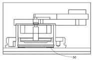
일 양태에서, 플레이트 부재, 차단 요소, 플런저, 에너지-저장 요소 및 작동 부재를 구비하는 어플리케이터가 제공된다. 일 실시예에서, 플레이트 부재는 상부 표면과 하부 표면을 가지는 강성 플레이트 부재이다. 추가 실시예에서. 플레이트 부재는 적어도 하나의 개구를 포함한다. 차단 요소는 플레이트 부재의 상부 표면과 접촉되어 있고, 일 실시예의 제 1 포지션과 제 2 포지션 사이에서 이동할 수 있다. 다른 실시예에서, 플런저는 근위 단부, 원위 단부, 및 그 사이에 뻗어있는 샤프트를 가진다. 샤프트의 근위 단부는 제 1 포지션에 있는 차단 부재에 의해 적어도 부분적으로 보유될 수 있다. 일 실시예에서, 에너지-저장 요소는 플레이트 부재의 하부 표면과 플런저의 원위 단부 사이에 포지셔닝된다. 추가 실시예에서, 작동 부재는 힘의 적용을 위한 외부 표면, 및 차단 요소가 제 1 포지션에 있는 경우 차단 요소와 기계적으로 연결되어 있는 적어도 하나의 표면을 가진다. 다른 실시예에서, 작동 부재의 외부 표면에 힘이 가해지는 경우, 작동 부재는 차단 요소를 제 1 포지션으로부터 제 2 포지션으로 이동시킨다. 차단 요소가 그 제 1 포지션으로부터 제 2 포지션으로 이동됨에 따라, 에너지-저장 요소는 해제된다.In an aspect, there is provided an applicator having a plate member, a blocking element, a plunger, an energy-storing element, and an actuating member. In one embodiment, the plate member is a rigid plate member having an upper surface and a lower surface. In a further embodiment. The plate member includes at least one opening. The blocking element is in contact with the upper surface of the plate member and is movable between a first position and a second position of an embodiment. In another embodiment, the plunger has a proximal end, a distal end, and a shaft extending therebetween. The proximal end of the shaft may be at least partially retained by the blocking member in the first position. In one embodiment, the energy-storage element is positioned between the lower surface of the plate member and the distal end of the plunger. In a further embodiment, the actuating member has an outer surface for application of force and at least one surface which is mechanically connected to the blocking element when the blocking element is in the first position. In another embodiment, when a force is applied to the outer surface of the actuating member, the actuating member moves the blocking element from the first position to the second position. As the blocking element is moved from its first position to its second position, the energy-storing element is released.
일 양태에서, 어플리케이터는 플런저 원위 단부의 바닥 표면 상에 포지셔닝되는 적어도 하나의 미세돌기를 더 구비한다. 다른 실시예에서, 적어도 하나의 미세돌기는 미세돌기 어레이(microprojection array), 피하 주사기(hypodermic needle) 또는 투관침(trocar)이다. 추가 실시예에서, 미세돌기 어레이는 복수의 가용성(dissolvable) 또는 침식성(erodible) 미세돌기를 구비한다. 다른 실시예들에서, 복수의 미세돌기들 중 적어도 일부는 미세돌기 어레이로부터 분리가능하다. 또 다른 실시예에서, 적어도 하나의 미세돌기는 적어도 하나의 치료제를 포함한다.In an aspect, the applicator further comprises at least one microprojection that is positioned on the bottom surface of the plunger distal end. In another embodiment, the at least one microprojection is a microprojection array, a hypodermic needle, or a trocar. In a further embodiment, the microprojection array has a plurality of dissolvable or erodible microprojections. In other embodiments, at least some of the plurality of microprojections are separable from the microprojection array. In another embodiment, at least one microprojection comprises at least one therapeutic agent.
일 실시예에서, 어플리케이터는 차단 요소와 기계적으로 연결되어 있는 적어도 하나의 굽힘 요소를 더 구비한다. 다른 실시예에서, 굽힘 요소는 차단 요소를 차단 요소 제 1 포지션에 있는 플런저 속으로 향하게 한다.In one embodiment, the applicator further comprises at least one bending element mechanically coupled to the blocking element. In another embodiment, the bending element directs the barrier element into the plunger in the first position of the barrier element.
일 실시예에서, 작동 부재는 차단 요소가 직선 변위를 가지게 한다. 다른 실시예에서, 작동 부재는 차단 요소가 회전 변위를 가지게 한다.In one embodiment, the actuating member causes the blocking element to have a linear displacement. In another embodiment, the actuating member causes the blocking element to have a rotational displacement.
일 실시예에서, 에너지-저장 요소는 탄성 에너지 요소이다. 다른 실시예에서, 탄성 에너지 요소는 압축 스프링, 코일 스프링 및 웨이브 스프링 중에서 선택된다.In one embodiment, the energy-storage element is an elastic energy element. In another embodiment, the elastic energy element is selected from a compression spring, a coil spring, and a wave spring.
일 실시예에서, 플런저 근위 단부는 그 제 1 포지션에 있는 차단 요소에 의해 보유될 수 있도록 치수형성되어 있다. 추가 실시예에서, 플런저 근위 단부는 플런저 샤프트를 적어도 부분적으로 에워싸는 렛지(ledge)에 의하여 그 제 1 포지션에 있는 차단 요소에 의해 보유된다.In one embodiment, the plunger proximal end is dimensioned to be retained by the blocking element in its first position. In a further embodiment, the plunger proximal end is retained by a blocking element in its first position by a ledge at least partially surrounding the plunger shaft.
일 실시예에서, 플런저 샤프트는 일정한 길이를 가지고, 에너지-저장 요소는 플런저가 샤프트의 길이보다 긴 거리를 움직이게 하는 힘을 플런저 상에 제공하기 위해서 선택된다.In one embodiment, the plunger shaft has a constant length and the energy-storage element is selected to provide a force on the plunger that causes the plunger to move a distance that is greater than the length of the shaft.
일 실시예에서, 플레이트의 적어도 하나의 개구는 원형, 타원형, 직사각형 및 정사각형 중에서 선택된 형상을 가진다.In one embodiment, the at least one opening of the plate has a shape selected from a circle, an ellipse, a rectangle, and a square.
일 실시예에서, 어플리케이터는 하우징 부재를 더 구비한다. 다른 실시예에서, 하우징 부재는 작동 부재의 외부 표면이 접근될 수 있는 개구를 포함한다. 다른 실시예에서, 하우징 개구는 작동 부재의 외부 표면의 적어도 일부를 수용할 수 있는 크기를 가진다. 다른 실시예에서, 하우징은 하우징을 대상에 고정하기 위해서 접착제가 그 위에 도포되거나 도포될 수 있는 표면을 포함한다. 추가 실시예에서, 접착제 레이어는 적어도 하나의 미세돌기를 적어도 부분적으로 둘러싼다. 또 다른 실시예에서, 플런저 샤프트의 길이는 접착제가 그 위에 도포되거나 도포될 수 있는 표면을 넘어서 뻗어있는 정도이다.In one embodiment, the applicator further comprises a housing member. In another embodiment, the housing member includes an opening through which the exterior surface of the actuating member can be approached. In another embodiment, the housing opening is sized to accommodate at least a portion of the exterior surface of the actuating member. In another embodiment, the housing includes a surface onto which an adhesive can be applied or applied to secure the housing to the object. In a further embodiment, the adhesive layer at least partially surrounds at least one microprojection. In yet another embodiment, the length of the plunger shaft is such that the adhesive extends beyond the surface onto which it can be applied or applied.
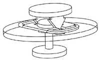
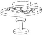
일 실시예에서, 어플리케이터는 플런저 원위 단부의 원위 표면 상에 포지셔닝되는 보강 부재를 더 구비하고, 여기서 보강 부재는 적어도 하나의 미세돌기를 구비한다. 추가 실시예에서, 보강 부재는 플런저 원위 단부로부터 분리가능하다. 다른 실시예에서, 보강 부재는 플런저 원위 단부의 원위 표면에 인접한 지지 레이어 및 접착제 레이어를 구비하고, 여기서 적어도 하나의 미세돌기는 접착제 레이어의 원위에 포지셔닝된다. 또 다른 실시예에서, 적어도 하나의 미세돌기는 접착제 레이어의 원위에 포지셔닝되는 미세돌기 어레이이다.In one embodiment, the applicator further comprises a reinforcing member that is positioned on the distal surface of the plunger distal end, wherein the reinforcing member has at least one microprojection. In a further embodiment, the reinforcing member is detachable from the plunger distal end. In another embodiment, the stiffening member has a support layer and an adhesive layer adjacent the distal surface of the plunger distal end, wherein at least one microprojection is positioned over the circle of adhesive layer. In yet another embodiment, the at least one microprojection is a microprojection array that is positioned over a circle of an adhesive layer.
실시예들에서, 적어도 플레이트와 플런저는 탄성률이 약 0.5 KSI 내지 500 KSI인 재료로 형성된다. 다른 실시예들에서, 적어도 플레이트와 플런저는 금속으로 형성된다. 추가 실시예에서, 적어도 차단 부재는 탄성률이 약 0.5 KSI 내지 500 KSI인 재료로 형성된다. 또 다른 실시예에서, 차단 부재는 금속으로 형성된다. 실시예들에서, 금속은 스테인리스 스틸, 탄소강, 티타늄 및 이들의 합금 중에서 선택된다.In embodiments, at least the plate and the plunger are formed of a material having a modulus of elasticity between about 0.5 KSI and 500 KSI. In other embodiments, at least the plate and the plunger are formed of metal. In a further embodiment, at least the barrier member is formed of a material having a modulus of elasticity of about 0.5 KSI to 500 KSI. In yet another embodiment, the barrier member is formed of a metal. In embodiments, the metal is selected from stainless steel, carbon steel, titanium and alloys thereof.
일 실시예에서, 어플리케이터는 에너지-저장 요소와 플런저 원위 단부의 근위 표면 사이에 포지셔닝되는 댐퍼를 더 구비한다.In one embodiment, the applicator further comprises a damper positioned between the energy-storage element and the proximal surface of the plunger distal end.
추가 양태에서, 적어도 하나의 치료제를 대상자에게 전달하기 위한 방법이 고려되어 있다. 일 실시예에서, 방법은, 어플리케이터 플런저의 원위 단부 상에 포함되어 있는 미세돌기 어레이를 대상자의 피부 부위에 적용하는 단계; 액추에이터를 제 1 포지션으로부터, 액추에이터가 차단 요소와 기계적으로 연결되는 제 2 포지션으로 작동시키기 위해서 어플리케이터 작동 부재의 외부 표면에 접촉하는 단계; 차단 요소를 플런저의 근위 단부와 접촉되는 제 1 포지션으로부터 제 2 포지션으로 이동시키는 단계; 플런저를 차단 부재와 접촉되어 있는 제 1 포지션으로부터 제 2 포지션으로 해제하는 단계; 플런저를 대상자의 피부와 접촉되도록 전개하기 위해서 에너지-저장 요소를 해제하는 단계; 및 적어도 하나의 치료제를 미세돌기 어레이로부터 대상자에게 전달하는 단계;를 구비한다. 다른 실시예에서, 방법은 어플리케이터를 대상자의 피부에 부착하는 단계를 추가로 구비한다. 추가 실시예에서, 차단 요소를 이동시키는 단계는 후퇴된 포지션으로부터 전개된 포지션으로의 플런저의 이동을 달성한다. 다른 실시예에서, 작동 부재의 외부 표면에 접촉하는 단계는 후퇴된 포지션으로부터 전개된 포지션으로의 플런저의 이동을 달성한다. 추가 실시예에서, 전개된 포지션에 있는 플런저는 미세돌기 어레이를 그 위에 붙일 수 있는 플런저의 원위 단부가 피부의 표면 아래에 포지셔닝되도록 평형 포지션(equilibrium position)을 가진다. 또 다른 실시예에서, 평형 포지션은 대상자의 피부의 표면 아래로 약 0.03 인치 내지 0.2 인치에 있다. 다른 실시예에서, 방법은 보강 부재와 미세돌기 어레이가 대상자의 피부 상에 보유되도록 보강 부재를 분리하는 단계를 추가로 구비한다.In a further aspect, a method for delivering at least one therapeutic agent to a subject is contemplated. In one embodiment, the method includes applying a microprojection array, which is contained on a distal end of an applicator plunger, to a skin region of a subject; Contacting the actuator from an outer surface of the applicator operating member to actuate the actuator from a first position to a second position in which the actuator is mechanically coupled to the blocking element; Moving the barrier element from a first position in contact with the proximal end of the plunger to a second position; Releasing the plunger from a first position in contact with the blocking member to a second position; Releasing the energy-storing element to deploy the plunger in contact with the subject ' s skin; And transferring at least one therapeutic agent from the microprojection array to the subject. In another embodiment, the method further comprises attaching the applicator to the subject's skin. In a further embodiment, moving the blocking element achieves movement of the plunger from the retracted position to the deployed position. In another embodiment, contacting the outer surface of the actuating member achieves movement of the plunger from the retracted position to the deployed position. In a further embodiment, the plunger in the deployed position has an equilibrium position such that the distal end of the plunger, onto which the microprojection array can be affixed, is positioned below the surface of the skin. In another embodiment, the equilibrium position is about 0.03 inches to 0.2 inches below the surface of the subject ' s skin. In another embodiment, the method further comprises separating the reinforcing member such that the reinforcing member and the microprojection array are held on the skin of the subject.
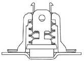
다른 양태에서, 어플리케이터는, 상부 표면과 하부 표면 및 적어도 하나의 개구를 가지는 평평한 플레이트; 플레이트 부재의 상부 표면과 접촉되어 있는 평평한 굽힘 요소로서, (ⅰ) 제 1 포지션과 제 2 포지션 사이에서 이동할 수 있는 갭을 가지고 그리고 (ⅱ) 평평한 부재 내의 개구와 갭을 정렬하도록 포지셔닝되는, 평평한 굽힘 요소; 정렬된 갭과 개구 내부에서 미끄럼이동가능하게 배치되어 있는 플런저; 평평한 부재의 하부 표면과 플런저의 원위 단부 사이에 포지셔닝되는 에너지-저장 요소; 및 작동 부재;를 구비한다. 일 실시예에서, 플런저는 적어도 하나의 미세구조를 그 위에 보유할 수 있는 원위 단부가 있는 샤프트를 가진다. 추가 실시예에서, 플런저는, 갭이 제 1 포지션에 있는 경우에는 근위 단부가 갭에 의해 보유되되 갭이 제 2 포지션에 있는 경우에는 근위 단부가 갭을 통과할 수 있도록 치수형성되어 있는, 근위 단부를 가진다. 다른 실시예들에서, 작동 부재는 외부 표면 및 다면체 형상 부재를 가진다. 또 다른 실시예에서, 다면체 형상 부재는, 작동 부재의 외부 표면이 에너지 저장 요소의 해제를 달성하기에 충분한 힘으로 접촉되어 있는 경우 그 제 1 포지션과 제 2 포지션 사이에서 갭을 이동시킬 수 있도록 치수형성되어 있다. 추가 실시예들에서, 다면체 형상 부재는 2개 내지 8개의 면을 구비한다. 다른 추가 실시예들에서, 다면체 형상 부재는 플런저의 근위 단부를 수용할 수 있도록 치수형성되어 있는 갭을 가진다.In another aspect, an applicator includes a flat plate having an upper surface and a lower surface and at least one opening; A flat bending element in contact with the upper surface of the plate member, the flat bending element having (i) a gap that is movable between a first position and a second position, and (ii) Element; A plunger slidably disposed within the aperture and the aligned gap; An energy-storing element positioned between the lower surface of the flat member and the distal end of the plunger; And an operating member. In one embodiment, the plunger has a shaft with a distal end capable of holding at least one microstructure thereon. In a further embodiment, the plunger has a proximal end that is retained by the gap when the gap is in the first position and a proximal end that is dimensioned to pass through the gap if the gap is in the second position. . In other embodiments, the actuating member has an outer surface and a polyhedral shaped member. In another embodiment, the polyhedral shaped member is dimensioned such that the outer surface of the actuating member is movable with a force sufficient to achieve release of the energy storage element, and between the first position and the second position, Respectively. In further embodiments, the polyhedral shaped member has two to eight sides. In other further embodiments, the polyhedral shaped member has a gap dimensioned to accommodate the proximal end of the plunger.
일 실시예에서, 에너지-저장 요소는 탄성 에너지 요소이다. 다른 실시예들에서, 탄성 에너지 요소는 압축 스프링, 코일 스프링, 웨이브 스프링 중에서 선택된다.In one embodiment, the energy-storage element is an elastic energy element. In other embodiments, the elastic energy element is selected from a compression spring, a coil spring, and a wave spring.
일 실시예에서, 플런저의 근위 단부는 플런저 샤프트를 적어도 부분적으로 에워싸는 렛지에 의하여 그 제 1 포지션에 있는 갭에 의해 보유될 수 있도록 치수형성되어 있다.In one embodiment, the proximal end of the plunger is dimensioned such that it can be retained by a gap in its first position by a ledge at least partially surrounding the plunger shaft.
일 실시예에서, 플레이트 부재 개구는 원형, 타원형, 직사각형 및 정사각형 중에서 선택된 형상을 가진다. 다른 실시예에서, 개구는 플레이트 상의 중심에 위치된다.In one embodiment, the plate member openings have a shape selected from a circle, an ellipse, a rectangle, and a square. In another embodiment, the aperture is centered on the plate.
일 실시예에서, 적어도 굽힘 요소와 플런저는 탄성률이 약 0.5 KSI 내지 약 500 KSI인 재료로 형성된다. 다른 실시예들에서, 재료는 금속이다. 추가 실시예에서, 금속은 스테인리스 스틸, 탄소강, 티타늄 및 이들의 합금 중에서 선택된다.In one embodiment, at least the bending element and the plunger are formed of a material having a modulus of elasticity between about 0.5 KSI and about 500 KSI. In other embodiments, the material is a metal. In a further embodiment, the metal is selected from stainless steel, carbon steel, titanium and alloys thereof.
실시예들에서, 어플리케이터는 작동 부재의 외부 표면이 수용될 수 있는 개구가 있는 하우징 부재를 더 구비한다. 다른 실시예들에서, 하우징은 하우징을 대상에 고정하기 위해서 접착제가 그 위에 도포되거나 도포될 수 있는 표면을 포함한다.In embodiments, the applicator further comprises a housing member having an opening through which the exterior surface of the actuating member can be received. In other embodiments, the housing includes a surface onto which an adhesive may be applied or applied to secure the housing to the object.
실시예들에서, 플런저 샤프트는 일정한 길이를 가지고, 에너지-저장 요소는 플런저가 샤프트의 길이보다 긴 거리를 움직이게 하는 힘을 플런저 상에 제공하기 위해서 선택된다. 추가 실시예에서, 플런저 샤프트의 길이는 접착제가 그 위에 도포되거나 도포될 수 있는 표면을 넘어서 뻗어있는 정도이다.In embodiments, the plunger shaft has a constant length and the energy-storage element is selected to provide a force on the plunger that causes the plunger to move a distance greater than the length of the shaft. In a further embodiment, the length of the plunger shaft is such that the adhesive extends beyond the surface onto which it can be applied or applied.
실시예들에서, 적어도 하나의 미세돌기는 미세돌기 어레이, 피하 주사기 또는 투관침이다. 추가적인 실시예들에서, 미세돌기 어레이는 복수의 가용성 또는 침식성 미세돌기를 구비한다. 추가 실시예들에서, 복수의 미세돌기는 치료제를 포함한다. 다른 추가 실시예들에서, 복수의 미세돌기들 중 적어도 일부는 미세돌기 어레이로부터 분리가능하다. 또한 추가 실시예들에서, 어플리케이터는 플런저 원위 단부의 바닥 표면 상에 포지셔닝되는 보강 부재를 더 구비하고, 여기서 보강 부재는 적어도 하나의 미세돌기를 구비한다. 다른 실시예들에서, 보강 부재는 플런저 원위 단부로부터 제거가능하다. 추가적인 실시예들에서, 보강 부재는 플런저 원위 단부의 원위 표면에 인접한 지지 레이어 및 접착제 레이어를 구비하고, 여기서 적어도 하나의 미세돌기는 접착제 레이어의 원위에 포지셔닝된다. 추가 실시예들에서, 적어도 하나의 미세돌기는 접착제 레이어의 원위에 포지셔닝되는 미세돌기 어레이이다. 다른 추가 실시예들에서, 접착제 레이어는 적어도 하나의 미세돌기를 적어도 부분적으로 둘러싼다.In embodiments, the at least one microprojection is a microprojection array, a hypodermic syringe, or a trocar. In further embodiments, the microprojection array has a plurality of soluble or erodible microprojections. In further embodiments, the plurality of microprojections comprise a therapeutic agent. In other further embodiments, at least some of the plurality of microprojections are separable from the microprojection array. In still further embodiments, the applicator further comprises a reinforcing member that is positioned on the bottom surface of the plunger distal end, wherein the reinforcing member has at least one microprojection. In other embodiments, the stiffening member is removable from the plunger distal end. In further embodiments, the stiffening member has a support layer and an adhesive layer adjacent the distal surface of the plunger distal end, wherein at least one microprojection is positioned over a circle of the adhesive layer. In further embodiments, the at least one microprojection is a microprojection array that is positioned over the circle of the adhesive layer. In other further embodiments, the adhesive layer at least partially surrounds at least one microprojection.
실시예들에서, 어플리케이터는 에너지-저장 요소와 플런저 원위 단부의 근위 표면 사이에 포지셔닝되는 댐퍼를 더 포함한다.In embodiments, the applicator further comprises a damper positioned between the energy-storage element and the proximal surface of the plunger distal end.
또 다른 양태에서, 치료제를 전달하기 위한 방법이 고려되어 있다. 일 실시예에서, 방법은 어플리케이터에 붙어있는 미세돌기 어레이를 적용하는 단계; 액추에이터를 제 1 포지션으로부터 제 2 포지션으로 작동시키기 위해서 작동부재의 외부 표면에 접촉하는 단계로서, 이로써 갭은 제 1 포지션으로부터 제 2 포지션으로 이동되는, 단계; 플런저를 구속된 포지션으로부터 대상자의 피부와 접촉되는 전개된 포지션으로 해제하는 단계; 및 치료제를 미세돌기 어레이로부터 대상에게 전달하는 단계;를 구비한다. 일 실시예에서, 미세돌기 어레이는 플런저의 원위 단부에 붙어있다. 실시예들에서, 방법은 어플리케이터를 대상자의 피부에 부착하는 단계를 추가로 구비한다. 추가 실시예들에서, 미세돌기 어레이는 복수의 미세돌기를 구비하고, 전개된 포지션에 있는 플런저는 복수의 미세돌기들 중 적어도 일부를 그 위에 붙일 수 있는 플런저의 원위 단부가 피부의 표면 아래에 포지셔닝되도록 평형 포지션을 가진다. 추가 실시예들에서, 평형 포지션은 대상자의 피부의 표면 아래로 약 0.03 인치 내지 0.2 인치에 있다.In yet another embodiment, a method for delivering a therapeutic agent is contemplated. In one embodiment, the method includes applying a microprojection array attached to an applicator; Contacting the outer surface of the actuating member to actuate the actuator from the first position to the second position, whereby the gap is moved from the first position to the second position; Releasing the plunger from the restrained position into a deployed position in contact with the subject's skin; And transferring the therapeutic agent from the microprojection array to the object. In one embodiment, the microprojection array is attached to the distal end of the plunger. In embodiments, the method further comprises attaching the applicator to the subject's skin. In further embodiments, the microprojection array has a plurality of microprojections, and the plunger in the deployed position is configured such that the distal end of the plunger capable of affixing at least a portion of the plurality of microprojections thereon is positioned below the surface of the skin So as to have a balanced position. In further embodiments, the equilibrium position is about 0.03 inches to 0.2 inches below the surface of the subject ' s skin.
일 실시예에서, 플런저를 전개하는 단계는 보강 부재와 미세돌기 어레이가 대상자의 피부 상에 보유되도록 보강 부재를 분리하는 단계를 추가로 구비한다.In one embodiment, the step of deploying the plunger further comprises separating the reinforcing member such that the reinforcing member and the microprojection array are held on the skin of the subject.
현재의 디바이스, 장치, 방법 및 이와 유사한 것에 관한 추가적인 실시예들은 다음에 오는 발명의 상세한 설명, 도면, 예시 및 청구범위로부터 자명할 것이다. 전술한 것과 다음에 오는 발명의 상세한 설명으로부터 이해될 수 있는 바와 같이, 본 명세서에 기술되어 있는 특징들 및 이러한 특징들 중 2개 이상의 조합은 어느 것이든 이러한 조합에 포함되어 있는 특징들이 상호간에 모순되지 않는다면 본 발명의 범위 내에 포함되어 있다. 더욱이, 특징 또는 이러한 특징들의 조합은 어느 것이라도 본 발명의 실시예로부터 특별히 배제되지는 않을 것이다. 현재의 디바이스, 장치 및 방법에 관한 추가적인 양태와 이점은, 특히 첨부의 예시와 도면과 관련하여 고려하면서 다음에 오는 발명의 상세한 설명 및 청구범위에서 설명된다.Additional embodiments of the present devices, devices, methods, and the like will be apparent from the description, drawings, illustrations, and claims of the invention that follows. As can be appreciated from the foregoing and the following detailed description of the invention, the features described herein and combinations of two or more of these features, whatever the features contained in such combinations, Are included within the scope of the present invention. Moreover, neither the features nor any combination of these features will be specifically excluded from the embodiments of the present invention. Additional aspects and advantages of the present devices, devices and methods are set forth in the following detailed description and claims, particularly when taken in conjunction with the accompanying examples and drawings.
도 1a와 도 1b는 선택된 특징이 나타나 있는 예시적인 어플리케이터의 위에서 바라본 사시도이다.
도 2는 예시적인 어플리케이터의 측면도이다.
도 3은 예시적인 어플리케이터의 측면도이다.
도 4는 선택된 특징이 나타나 있는 예시적인 어플리케이터 디바이스의 측면도이다.
도 5a 내지 도 5c는 사용중인 예시적인 어플리케이터 디바이스의 측면도이다.
도 6은 예시적인 어플리케이터 디바이스의 측면도이다.
도 7은 선택된 특징이 나타나 있는 예시적인 어플리케이터 디바이스의 측면도이다.
도 8은 선택된 특징이 나타나 있는 예시적인 어플리케이터 디바이스의 측면도이다.
도 9에는 최종적인 뻗어있는 상태 또는 평형 상태에 있는 예시적인 어플리케이터 디바이스가 나타나 있다.
도 10은 디바이스용 예시적인 하우스의 저면도이다.
도 11에는 선택된 특징이 나타나 있는 예시적인 어플리케이터 디바이스가 나타나 있다.
도 12는 선택된 특징이 나타나 있는 예시적인 어플리케이터 디바이스의 분해도이다.
도 13a 내지 도 13c에는 선택된 특징이 나타나 있는 사용중인 예시적인 어플리케이터 디바이스가 나타나 있다.
여러 가지 어플리케이터 및 미세구조 어레이에 관한 두께 및 형상이 디바이스의 이해를 돕기 위해서 도면에서 과장되어 있다는 것을 알 수 있을 것이다. 이 도면들은 반드시 정확한 축적인 것은 아니다.Figures 1A and 1B are perspective views from above of an exemplary applicator in which selected features are shown.
2 is a side view of an exemplary applicator.
3 is a side view of an exemplary applicator.
4 is a side view of an exemplary applicator device in which selected features are shown.
Figures 5A-5C are side views of an exemplary applicator device in use.
6 is a side view of an exemplary applicator device.
7 is a side view of an exemplary applicator device in which selected features are shown.
Figure 8 is a side view of an exemplary applicator device in which selected features are shown.
Figure 9 shows an exemplary applicator device in its final extended or equilibrium state.
10 is a bottom view of an exemplary house for a device.
Figure 11 shows an exemplary applicator device in which selected features are shown.
12 is an exploded view of an exemplary applicator device in which selected features are shown.
13A-13C illustrate an exemplary applicator device in use with selected features shown.
It will be appreciated that the thickness and shape of the various applicators and microstructure arrays are exaggerated in the figures to aid understanding of the device. These figures are not necessarily accurate.
여러 가지 양태들은 이제 이하에서 더욱 충분하게 설명될 것이다. 그러나, 이러한 양태들은 여러 가지 다른 형태로 구체화될 수 있고, 본 명세서에 설명된 실시예들로 제한되는 것으로 해석되어서는 안된다. 오히려, 이 실시예들은 본 발명이 전체에 걸쳐 완전히 이해될 수 있도록 그리고 당해 기술분야에서의 통상의 기술자에게 그 발명의 사상이 충분하게 의미 전달되도록 제공된 것이다.Various aspects will now be described more fully below. These aspects, however, may be embodied in many different forms and should not be construed as limited to the embodiments set forth herein. Rather, these embodiments are provided so that this invention may be thoroughly understood in its entirety and that those skilled in the art will be able to convey the idea of the invention to those skilled in the art sufficiently.
본 발명의 실시는 이와 달리 지시되지 않는 한 당해 기술분야에서의 통상의 기술자가 이해할 수 있는 수준에서 화학, 생화학 및 약학과 관한 종래의 방법을 이용한다. 이러한 기술은 문헌에 충분하게 설명되어 있다. 예컨대, A.L. Lehninger 저 '생화학(Biocemistry)'(Worth Publishers, Inc., 증보판); Morrison 및 Boyd 저 '유기 화학(Organic Chemistry)'(Allyn and Bacon, Inc., 증보판); J. March 저 '고급 유기 화학(Advanced Organic Chemistry)'(McGraw Hill, 증보판); Remington 저 '약학의 과학 및 실제(The Science and Practice of Pharmancy)'(A. Gennaro, Ed., 20판); 및 Goodman & Gilman 저 '치료학적 약리학의 이해(The Pharmacological Basis of Therapeutics)'(Griffith Hardman,L. L. Limbird, A. Gilman, 10판)를 참조하기 바란다.The practice of the present invention employs conventional methods of chemistry, biochemistry, and pharmacology at levels understood by those of ordinary skill in the art, unless otherwise indicated. These techniques are fully described in the literature. For example, A.L. Lehninger, "Biocemistry" (Worth Publishers, Inc., Supplement); Morrison and Boyd, Organic Chemistry (Allyn and Bacon, Inc., supplement); J. March Advanced Organic Chemistry (McGraw Hill, Supplement); Remington, 'The Science and Practice of Pharmancy' (A. Gennaro, Ed., 20th edition); And Goodman & Gilman, "The Pharmacological Basis of Therapeutics" (Griffith Hardman, L. Limbird, A. Gilman, 10th ed.).
값의 범위가 제공되는 경우에는, 이 범위의 상한과 하한 사이의 각각의 중간 값 및 이 정해진 범위 내의 다른 정해진 값이나 중간 값은 본 명세서의 범위 내에 포함되어 있다. 예를 들어, 1 ㎛ 내지 8 ㎛의 범위가 정해진다면, 이는 2㎛, 3 ㎛, 4 ㎛, 5 ㎛, 6 ㎛ 및 7 ㎛도 명시적으로 개시되어 있을 뿐만 아니라 그 범위가 1 ㎛ 이상이면서 8 ㎛ 이하인 범위도 개시되도록 의도된 것이다.Where a range of values is provided, each intermediate value between the upper and lower limits of this range and other defined or intermediate values within this range are included within the scope of this specification. For example, if a range of 1 탆 to 8 탆 is specified, it is not only explicitly disclosed that 2 탆, 3 탆, 4 탆, 5 탆, 6 탆 and 7 탆, Mu] m or less are also intended to be disclosed.
Ⅰ.Ⅰ.정의 (Definitions)Definitions
본 명세서에서 사용되는 바와 같이, 단수 형태인 "한(a)", "하나의(an)" 및 "그(the)"는 문맥상 명확하게 이와 달리 지시하지 않는 한 복수의 대상을 포함한다. 따라서, 예컨대 "폴리머(polymer)"와 관련된 것은 단수의 폴리머 뿐만 아니라 2개 또는 그 이상의 상이한 폴리머를 포함하고, "첨가물(excipient)"과 관련된 것은 단수의 첨가물 뿐만 아니라 2개 또는 그 이상의 상이한 첨가물 및 이와 유사한 것을 포함한다.As used herein, the singular forms "a", "an" and "the" include plural referents unless the context clearly dictates otherwise. Thus, for example, reference to a "polymer" includes not only a singular polymer but also two or more different polymers, with reference to an "excipient" And the like.
본 발명을 기술하고 주장함에 있어서, 다음의 용어는 아래에서 기술되는 정의에 따라 사용될 것이다.In describing and claiming the present invention, the following terms will be used in accordance with the definitions set out below.
어플리케이터와 어레이에 대하여 논하자면, "아래쪽을 향하여(downward)"라는 용어는 종종 미세돌기가 피부 속으로 가압되는 방향을 기술하는데 사용되고, "위쪽을 향하여(upward)"라는 용어는 그 반대 방향을 기술하는데 사용된다. 그러나, 당해 기술분야에서의 통상의 기술자라면, 미세돌기가 피부 속으로 지구의 중력 방향에 대한 각도로, 또는 경우에 따라서는 지구의 중력 방향에 대한 각도에 대해 정반대 방향으로 가압되는 경우에 어플리케이터가 사용될 수 있다는 것을 알 수 있을 것이다. 본 명세서에서 설명되는 다수의 어플리케이터에서, 미세돌기를 가압하기 위한 에너지는 주로 에너지-저장 부재에 의해 제공되므로, 그 효율은 지구의 중력에 대한 피부의 배향에 의해 크게 영향을 받지는 않는다.With respect to the applicator and the array, the term "downward" is often used to describe the direction in which the microprojections are pressed into the skin, and the term " upward " . However, those of ordinary skill in the art will appreciate that an applicator may be used when the microprojections are pressed into the skin at an angle to the earth's gravitational direction, or in some cases in the opposite direction to an angle to the earth's gravitational direction You can see that it is. In many of the applicators described herein, the energy to press the micro-protrusions is primarily provided by the energy-storing member, so that its efficiency is not significantly affected by the skin's orientation to earth's gravity.
"미세돌기(microprotrusion 또는 microprojection)", "미세구조(microstructure)" 또는 "미세바늘(microneedle)"이라는 용어들은 각질층 또는 다른 생체막의 적어도 일부를 침투하거나 뚫도록 되어 있는 요소들을 지칭하기 위해서 본 명세서에서 호환가능하게 사용된다. 예를 들어, 설명되어 있는 미세구조는 본 명세서에서 제공되는 것에 추가하여 미국 특허 제6,219,574호에 기술되어 있는 마이크로블레이드, 미국 특허 제6,652,478호에 기술되어 있는 미세바늘, 및 미국 특허 공보 U.S.2008/0269685에 기술되어 있는 미세돌기를 포함할 수 있다.The terms "microprotrusion or microprojection", "microstructure" or "microneedle" are used herein to refer to elements that are intended to penetrate or puncture at least a portion of the stratum corneum or other biological membranes. It is used interchangeably. For example, the described microstructure can be used in addition to those provided herein, such as the microblades described in U.S. Patent No. 6,219,574, the microneedles described in U.S. Patent No. 6,652,478, and U.S. Patent Publication No. US2008 / 0269685 And the like.
"미세돌기 어레이(microprotrusion array)"라는 용어는 본 명세서의 목적에 부합하도록 미세돌기들, 미세돌기들 또는 미세바늘들의 2차원 또는 3차원 배열을 표시하는 것이 의도되어 있다. 이 배열은 반복되는 기하학적 패턴에 따라 규칙적일 수 있고 또는 불규칙적일 수 있다.The term " microprotrusion array "is intended to indicate a two-dimensional or three-dimensional array of microprojections, microprojections, or microneedles to meet the objectives of the present disclosure. This arrangement may be regular or irregular depending on the repeating geometric pattern.
"선택적인" 또는 "선택적으로"라는 용어는 차후에 기술되는 상황이 일어날 수도 일어나지 않을 수도 있다는 것을 의미해서, 발명의 상세한 설명은 그 상황이 발생하는 예시들 및 그 상황이 발생하지 않는 예시들을 포함한다.The term "optional" or "optionally" means that the subsequently described circumstances may or may not occur, so that the detailed description of the invention includes examples in which the situation occurs and examples in which the situation does not occur .
"실질적으로" 또는 "본질적으로"라는 용어는, 예컨대 80-85%, 80-90%, 80-95%, 85-90%, 85-95%, 90-95% 또는 몇몇 주어진 양 이상의 것과 같은 것을 거의 전체적으로 또는 완전히 의미한다.The term "substantially" or "essentially ", as used herein, refers to an amount that is, for example, 80-85%, 80-90%, 80-95%, 85-90%, 85-95%, 90-95% Almost entirely or completely.
본 출원에서, 미세바늘이 침투하는 생체막과 같은 "피부"에 대한 참조사항이 편의상 기재된다. 당해 기술분야에서의 통상의 기술자라면 대부분의 예시들 또는 모든 예시들에 있어서 동일한 발명의 원리가, 예컨대 수술 동안 노출되는 구강 또는 생체막의 내부를 가리키는 것과 같은 다른 생체막을 침투하는 미세바늘의 사용에 적용된다는 것을 알 수 있을 것이다. 다른 실시예들에서, 발명의 원리는 세포벽에 대한 미세바늘의 사용에 적용될 수 있다. 예를 들어, 본 명세서에 기술된 미세바늘은 표면 상에 존재하는 특정 세포가 미세바늘에 의해 표적이되는 경우에 피부의 상태를 처리하는데 사용될 수 있다.In the present application, reference to a "skin" such as a biomembrane into which a microneedle penetrates is described for convenience. It will be appreciated by those of ordinary skill in the art that the principles of the same invention in most or all of the examples apply to the use of microneedles to penetrate other biological membranes, such as, for example, You can see that. In other embodiments, the principles of the invention may be applied to the use of microneedles for cell walls. For example, the microneedles described herein can be used to treat the condition of the skin when certain cells present on the surface are targeted by microneedles.
"경피(transdermal)"라는 용어는 피부 속으로의 약제의 전달 및/또는 피부를 통한 약제의 전달에 관한 것이고, 또는 국소 치료 및/또는 전신 치료에 관한 것이다. 동일한 발명의 원리는 복강경이나 내시경과 같은 시술 또는 수술 동안 노출되거나 접근가능한 구강의 내부, 위장관, 혈액-뇌 장벽 또는 다른 신체 조직이나 장기 또는 생체막을 가리키는 것과 같은 다른 생체막을 통한 투여에 적용된다.The term "transdermal" relates to the delivery of medicament into the skin and / or the delivery of medicament through the skin, or to topical and / or systemic treatment. The same inventive principles apply to administration through other biological membranes, such as the interior of the oral cavity, the gastrointestinal tract, the blood-brain barrier or other body tissues or organ or biological membranes exposed or accessible during procedures such as laparoscopy or endoscopy or surgery.
Ⅱ.Ⅱ.미세구조Microstructure어플리케이터Applicator (Microstructure Applicators) (Microstructure Applicators)
본 발명의 대상을 상세하게 설명하기 전에, 본 발명이 달라질 수 있는 것과 같은 특별한 재료 또는 디바이스 구조로 제한되는 것은 아니라는 점은 이해되어야 한다. 본 명세서에서 사용되는 용어가 특정 실시예들을 설명만 하기 위한 것이지 이를 제한하도록 의도된 것은 아니라는 것 역시 이해되어야 한다.Before describing the subject matter of the present invention in detail, it is to be understood that the invention is not limited to such specific materials or device structures as may be varied. It is also to be understood that the terminology used herein is for the purpose of describing particular embodiments only and is not intended to be limiting thereof.
A.차단 요소 해제어플리케이터 (Blocking Element Release Applicator)A.Block offthe applicatorelements(Blocking Element Release Applicator)
일 양태에서, 바늘, 미세바늘, 미세돌기, 미세 구조 또는 이들의 어레이의 전달을 위한 어플리케이터가 본 명세서에 기술되어 있다. 어플리케이터는 액추에이터 또는 작동 부재, 차단 요소 내지 부재, 플런저 내지 피스톤, 적어도 하나의 개구를 가지는 플레이트 내지 홀더 및 에너지-저장 요소를 구비한다. 어플리케이터는 차단 부재 내지 요소에 의해 보유되는 플런저를 해제하기 위해서 한계치 이상으로 작동 부재에 힘을 가하여 조작된다.In one aspect, applicators for delivery of needles, microneedles, microprojections, microstructures, or arrays thereof are described herein. The applicator comprises an actuator or actuation member, a blocking element or member, a plunger or piston, a plate or holder having at least one opening, and an energy-storage element. The applicator is operated by exerting a force on the actuating member above the limit to release the plunger held by the blocking member or element.
어플리케이터(10)는 상부 표면 내지 근위 표면(34) 및 하부 표면, 하면 내지 원위 표면(36)을 가지는 평평한 플레이트 부재 내지 홀더(12)를 포함한다. 플레이트 부재는 플레이트를 통해 뻗어있는 적어도 하나의 개구(22)를 가진다. 플레이트 부재는 가요성일 수 있고, 강성 또는 실질적으로 강성일 수 있다. 바람직하게는, 아래에서 보다 충분하게 설명되는 바와 같이, 플레이트 부재는 충분한 기계적 강도를 가지고 그리고/또는 플런저 원위 단부(28)를 따라 에너지 저장 요소(20)를 구속시킬 정도로 충분히 강성이다. 적어도 하나의 개구는 플런저 또는 피스톤(16)의 적어도 일부가 개구를 통과할 수 있도록 치수형성되어 있다. 일 실시예에서, 적어도 하나의 개구는 플런저가 그 내부에 미끄럼이동가능하게 수용될 수 있는 적합한 치수를 가진다. 차단 요소 내지 보유 요소(14)는 적어도 하나의 개구에 있거나 그 근처에 있는 플레이트의 근위 표면에 인접하여 포지셔닝된다. 차단 요소는 플런저가 차단 요소에 의해 보유되어 있는 것으로 도 1a에 나타나 있는 제 1 포지션(38)으로부터, 플런저가 해제되어 있는 것으로 도 1b에 나타나 있는 제 2 포지션(40)으로 이동할 수 있다. 차단 요소는 잠금 시스템, 하나 이상의 패스너 및/또는 접착제와 같은 기계적 부재를 포함하되 이에 제한되지 않는 적합한 방식으로 플레이트에 의해 보유되거나 플레이트에 고정될 수 있다.The
어플리케이터는 근위 단부 내지 근위부(24)와 원위 단부 내지 원위부(28)가 있는 중심 기둥 내지 샤프트(26)를 가지는 플런저, 피스톤 내지 다른 기다란 구조체(16)를 더 포함한다. 샤프트는 바람직하게는 근위 단부 내지 근위부와 원위 단부 내지 원위부 사이에 적어도 부분적으로 뻗어있다. 플런저의 근위 단부는 플레이트에 있는 적어도 하나의 개구를 통해 적어도 부분적으로 미끄럼이동가능하게 포지셔닝가능하도록 크기와 형상을 가지는 것이 바람직하다. 플런저가 임의의 적합한 형상 또는 크기를 가질 수 있다는 것을 알 수 있다. 적어도 도 1b와 도 2에 나타나 있는 바와 같이, 하나의 적합한 형상은 원형 또는 실린더형 근위 단부를 가진 실린더형 샤프트를 구비한다. 특정 실시예에서, 원위 단부는 원형 플레이트 형상을 가진다. 그러나, 다른 형상이 직사각형 프리즘 또는 다른 다면체 프리즘을 포함하되 이에 제한되지 않는다는 것을 알 수 있을 것이다. 샤프트, 근위 단부 및 원위 단부가 상이한 기하학적 형상을 각각 가질 수 있다는 것을 추가로 알 수 있을 것이다. 일 예시로서, 샤프트와 근위 단부는 원위 단부가 정사각형 또는 직사각형 형상을 가지는 실린더형일 수 있다. 근위 단부와 원위 단부 중 어느 하나 또는 모두가 원형, 정사각형, 직사각형, 타원형 또는 불규칙적인 형상을 가지는 플레이트일 수 있다는 것 역시 알 수 있을 것이다. 일 실시예에서, 근위 단부는 중심 샤프트의 직경보다 더 넓은 직경을 가진다. 플런저는 적어도 하나의 플레이트 개구 내부에 적어도 부분적으로 미끄럼이동가능하게 배치되어 있으므로, 플런저의 근위 단부는 적어도 부분적으로 개구를 통과할 수 있다. 일 실시예에서, 플런저의 근위 단부는 통상적으로 차단 요소의 적어도 일부를 수용할 수 있도록 치수형성되어 있는 개구, 컷-아웃, 에지, 렛지 또는 언더컷이 있는 플런저 보유 영역(32)을 포함한다. 도 1a에 나타나 있는 실시예에서, 플런저 근위부는 요소가 제 1 포지션에 있는 경우 차단 요소 중 적어도 일부를 수용하기 위한 컷-아웃부를 포함한다. 이 실시예에서, 플런저의 적어도 근위 단부는 차단 요소의 일부 상에 착좌되고 차단 요소의 일부에 의해 보유된다. 플런저 근위 단부는 플런저 근위 단부는 구속된 포지션 또는 구속되어 있는 포지션에 유지된다. 제 2 포지션에서, 차단 요소는 플런저 근위 단부의 컷-아웃부로부터 제거된다. 플런저 근위 단부는 그 후 환자의 피부를 향하여 적어도 하나의 개구를 통해 자유롭게 미끄럼이동한다. 일 실시예에서, 플런저의 근위 단부는 플런저 샤프트를 적어도 부분적으로 에워싸는 렛지에 의하여 그 제 1 포지션에 있는 적어도 하나의 개구에 의해 구속될 수 있도록 치수형성되어 있다. 따라서, 플런저의 근위 단부의 렛지, 언더사이드 또는 언더컷의 적어도 일부는 차단 요소의 상부 또는 근위 표면 상에 착좌된다. 바람직하게는, 플런저 근위 단부는 차단 요소에 의해 적어도 부분적으로 둘러싸여 있으므로, 근위 단부는 적어도 플런저의 근위 단부의 에지 둘레에서 차단 요소의 근위 표면에 의해 지지되거나 차단 요소의 근위 표면 상에 보유된다. 플런저의 근위 단부는 적합한 크기와 형상을 가질 수 있다.The applicator further includes a plunger, piston or other
도 1a와 도1b에는 차단 요소를 제 1 포지션으로부터 제 2 포지션으로 이동시키기 위한 하나의 예시적인 구성이 나타나 있다. 도 1a에 나타나 있는 바와 같이, 차단 요소의 일부는 플런저의 근위부에 있는 컷아웃부 또는 플런저 보유 영역(32) 속에 들어맞는다. 액추에이터 내지 작동 부재 내지 요소(18)는 차단 요소에 접촉하여 차단 요소를 그 제 1 포지션으로부터 그 제 2 포지션으로 이동시키는데 사용된다. 작동 부재(18)는 통상적으로 차단 요소의 적어도 일 단부에 있거나 그 근처에 있는 플레이트의 근위 표면에 인접하여 포지셔닝된다. 작동 부재는 도 1a에 나타나 있는 바와 같은 제 1 포지션(44)으로부터, 도 1b에 나타나 있는 바와 같이 작동 부재가 차단 부재에 접촉하여 차단 부재를 그 제 2 포지션(40)으로 이동시키는 제 2 포지션(46)으로 이동시킬 수 있다. 작동 부재는, 잠금 시스템, 하나 이상의 패스너 및/또는 접착제와 같은 기계적 부재를 포함하되 이에 제한되지 않는 적합한 방식으로 플레이트에 의해 보유되거나 플레이트에 고정될 수 있다. 예시적인 일 실시예에서, 작동 부재는 도 1a와 도 1b에 나타나 있는 바와 같이 액추에이터 홀더 내지 리테이너(42)에 의해 플레이트에 고정된다.Figures 1A and 1B show one exemplary arrangement for moving a blocking element from a first position to a second position. As shown in FIG. 1A, a portion of the barrier element fits within the cutout or
액추에이터가 제 1 포지션(44)(도 1a)으로부터 제 2 포지션(도 1b)으로 이동됨에 따라, 액추에이터는 차단 요소에 접촉하고, 차단 요소를 그 제 1 포지션(38)으로부터 그 제 2포지션(40)으로 이동시키고, 이로써 플런저를 해제할 수 있다. 나타나 있는 예시적인 실시예에서, 차단 요소는 제 1 포지션으로부터 제 2 포지션으로 중심의 보유 지점(41)을 중심으로 피벗운동한다. 차단 요소는 적합한 형상과 크기를 가질 수 있다. 예시적인 실시예에서, 차단 요소는 작동 부재에 의하여 접촉되는 돌기를 포함한다. 도 1a와 도 1b의 실시예에서, 차단 요소는 L자형이다. 다른 실시예들에서, 차단 요소는 다면체 형상 또는 불규칙적인 형상이다. 작동 부재가 그 제 1 포지션으로부터 그 제 2 포지션으로 이동함에 따라, 작동 부재는 차단 부재 돌기에 접촉하고, 차단 부재를 피벗운동가능하게 이동시킨다. 차단 부재가 피벗 지점(41)을 중심으로 피벗운동함에 따라, 플런저를 보유하는 차단 부재의 일부는 플런저 보유 영역(32)으로부터 멀리 이동하고, 이로써 플런저를 해제할 수 있다. 일 실시예에서, 작동 부재는 다면체 형상을 가진다. 실시예들에서, 작동 부재는, 넓은 베이스를 가지면서 좁은 팁 쪽으로 점점 가늘어지는 쐐기(wedge) 형상을 가진다. 도 1a의 실시예에서, 차단 부재에 접촉하는 작동 부재의 영역은 경사진 형상을 가진다. 따라서, 작동 부재가 이동됨에 따라, 작동 부재의 점진적으로 넓어지는 부분은 차단 부재 돌기에 접촉한다. 도 2에 나타나 있는 바와 같이, 다른 실시예에서, 작동 부재는 아래쪽을 향하는 방향으로 이동하여, 차단 부재에 접촉하고 차단 부재를 플런저 보유 영역(32)과의 접촉으로부터 이동시킨다. 차단 부재와 작동 부재가 각각, 작동 부재가 플런저 근위 단부와의 맞닿음으로부터 떨어지도록 또는 그 맞닿음을 벗어나도록 차단 부재를 밀어내거나 이동시키거나 회전시킬 수 있기에 적합한 형상을 가질 수 있다는 것을 알 수 있을 것이다. 실시예들에서, 작동 부재는 차단 부재가 직선 변위 또는 회전 변위를 가지게 한다. 실시예들에서, 플런저와 차단 요소는 플런저의 중심축(또는 회전축)에 가까이 설치된다.As the actuator moves from the first position 44 (FIG. 1A) to the second position (FIG. 1B), the actuator contacts the blocking element and moves the blocking element from its
압력은 수동식 또는 기계식을 포함하는 적합한 수단에 의해 작동 부재(18)를 그 제 1 포지션(44)으로부터 그 제 2 포지션(46)으로 이동시키도록 가해질 수 있다. 압력이 수동으로 가해지는 경우, 작동 부재는 사용자에 의한 접촉에 적합한 외부 표면을 가지고, 또는 이와 달리 사용자가 적절한 압력을 작동 부재에 가할 수 있는 구조를 포함한다. 제한 없는 실시예들에서, 약 0.5 lb 내지 10 lb의 힘이 작동 부재에 가해진다.The pressure can be applied to move the actuating
디바이스를 작동시키는데 요구되는 힘은 작동 부재를 제 1 포지션으로부터 제 2 포지션으로 이동시키는데 필요로 하는 것이므로, 차단 부재를 제 1 포지션으로부터 제 2 포지션으로 이동시킨다. 힘은 부재들이 만들어지는 재료의 정밀한 치수 및 재료 특성(예컨대 영률)에 좌우된다. 다른 실시예들에서, 힘은 마찰 계수, 접촉력 및/또는 기계적 이점(mechnical advantage)에 좌우된다. 마찰 계수는 마감처리 및/또는 코팅에 의해 수정될 수 있다. 접촉력은 스프링 상수, 및 에너지 저장 요소에 저장되는 에너지에 좌우된다. 기계적 이점은 설계 요소 및 그 정밀한 치수에 좌우된다.The force required to operate the device is required to move the actuating member from the first position to the second position, thus moving the blocking member from the first position to the second position. The force depends on the precise dimensions of the material from which the members are made and the material properties (e.g., Young's modulus). In other embodiments, the force depends on the friction coefficient, the contact force, and / or the mechanical advantage. The coefficient of friction can be modified by finishing and / or coating. The contact force depends on the spring constant and the energy stored in the energy storage element. The mechanical advantage depends on the design element and its precise dimensions.
플런저(16)의 바닥 표면(30)은 적어도 하나의 바늘, 미세돌기 어레이, 수동 경피 패치, 또는 하나 이상의 치료제의 경피 투여를 위한 다른 전달 디바이스를 더 포함한다. 예시적인 실시예에서, 미세돌기 어레이(48)는 플런저의 바닥 표면(30)에 붙어있거나 부착되거나 부착되게 되고 또는 플런저의 바닥 표면과 일체를 이룬다. 일 실시예에서, 전달 디바이스는 플런저 원위 표면에 제거가능하게 부착된다. 미세돌기의 전체적인 특징들은, 예컨대 미국 공보 2008/0269685, 2011/0276028 및 미국 특허 제7,416,541호, 제 7,578,954호, 제 7,108,681호에 기술되어 있고, 이들 각각은 참조사항으로 본 명세서에 통합되어 있다. 실시예들에서, 미세돌기는 피하 주사기 또는 투관침이다. 추가 실시예들에서, 미세돌기 어레이는 복수의 미세돌기를 구비하고, 이들 중 적어도 일부는 가용성 또는 침식성 미세돌기이다. 추가 실시예들에서, 미세돌기들 중 적어도 일부는 적어도 하나의 치료제를 포함한다. 게다가, 미세돌기들 중 적어도 일부는 미세돌기 어레이로부터 분리가능하다. 분리가능한 미세돌기 어레이는 미국 특허 출원 61/745,513에 기술되어 있고, 이는 참조사항으로 본 명세서에 통합되어 있다.The
제한 없는 일 실시예에서, 미세돌기 어레이 또는 다른 전달 디바이스는 접착제를 사용하여 플런저에 붙어있거나 부착된다. 적합한 접착제에는 아크릴 접착제, 아크릴산염 접착제, 감압 접착제, 양면 접착 테이프, 부직포나 다공성 필름으로 코팅된 양면 접착제 및 UV 경화성 접착제가 포함되지만 이에 제한되는 것은 아니다. 당해 기술분야에 알려진 의료용 디바이스 접착제가 적합할 수 있다는 것을 알 수 있을 것이다. 다른 실시예에서, 미세구조 어레이 또는 다른 전달 디바이스의 적어도 일부는 플런저 원위 단부의 적어도 일부와 일체를 이룬다.In one non-limiting embodiment, the microprojection array or other delivery device is attached to or attached to the plunger using an adhesive. Suitable adhesives include, but are not limited to, acrylic adhesives, acrylate adhesives, pressure sensitive adhesives, double-sided adhesive tapes, double-sided adhesives coated with a nonwoven or porous film, and UV curable adhesives. It will be appreciated that medical device adhesives known in the art may be suitable. In another embodiment, at least a portion of the microarchitecture array or other delivery device is integral with at least a portion of the plunger distal end.
본 발명에서 사용하기 위한 미세바늘 및 다른 돌기의 크기는 제조 기술 내지 정밀 응용분야에 관한 함수일 수 있다. 그러나, 일반적으로, 실제로 사용되는 미세바늘과 다른 미세돌기는 약 20 미크론 내지 약 1000 미크론의 길이, 보다 바람직하게는 약 50 미크론 내지 약 750 미크론의 길이, 가장 바람직하게는 약 100 미크론 내지 약 500 미크론의 길이를 가지는 것이 예상될 수 있다. 종종 미세돌기가, 예컨대 허벅지, 엉덩이, 팔 또는 몸통과 같은 신체 상의 일부 적합한 지점의 적용처에서 피부의 각질층을 통해 적어도 부분적으로 침투하기에 충분한 길이를 가지는 것이 요구될 수 있다.The size of the microneedles and other protrusions for use in the present invention may be a function of manufacturing techniques or of precision applications. However, in general, the microneedles and other microprojections actually used will have a length of from about 20 microns to about 1000 microns, more preferably from about 50 microns to about 750 microns, most preferably from about 100 microns to about 500 microns Lt; RTI ID = 0.0 > of < / RTI > Often it may be required that the microprojections have a length sufficient to at least partially penetrate through the stratum corneum of the skin at the application of some suitable point on the body, such as the thighs, hips, arms or trunk.
플레이트 부재, 플런저 및 차단 부재는 적합한 재료로 형성될 수 있다. 제한 없는 일 실시예에서, 플레이트 부재 및 플런저는 탄성률이 약 0.5 KSI 내지 500 KSI인 금속으로 적어도 부분적으로 형성된다. 일 실시예에서, 플레이트 부재 또는 플런저 중 적어도 하나는 스테인리스 스틸, 탄소강, 티타늄 및 이들의 합금을 포함하되 이에 제한되지 않는 금속으로 형성된다.The plate member, the plunger, and the blocking member may be formed of a suitable material. In one non-limiting embodiment, the plate member and the plunger are at least partially formed of a metal having a modulus of elasticity between about 0.5 KSI and 500 KSI. In one embodiment, at least one of the plate member or the plunger is formed of a metal including, but not limited to, stainless steel, carbon steel, titanium, and alloys thereof.
어플리케이터는 플레이트 부재의 하부 표면과 플런저의 원위 단부 사이에 적어도 부분적으로 포지셔닝되는 적어도 하나의 에너지-저장 요소(20)를 더 포함한다. 바람직하게는, 에너지 저장 요소(들)은 플레이트와 플런저 원위 단부 사이에 보유되고 그리고/또는 지지된다.The applicator further includes at least one energy-storage element (20) that is at least partially positioned between the lower surface of the plate member and the distal end of the plunger. Preferably, the energy storage element (s) are held and / or supported between the plate and the plunger distal end.
적합한 에너지 저장 요소는 스프링 또는 탄성 구성요소를 포함하되 이에 제한되지 않는 것으로 고려되어 있다. 제한 없는 실시예들에서, 에너지 저장 요소는 탄성 저장 요소, 압축 스프링, 코일 스프링 또는 웨이브 스프링 디바이스이다. 플런저가 차단 부재에 의해 보유되는 경우 에너지-저장 부재는 저장된 에너지의 고 에너지 포지션으로 구속되고, 플런저가 차단 부재로부터 해제되는 경우 에너지-저장 부재는 그 저장된 에너지를 해제하고 그렇게 함으로써 플런저를 이동시킨다. 플런저 원위 단부가 차단 부재에 의해 보유되는 경우, 에너지 저장 요소는 통상적으로 플런저의 근위 표면과 플레이트 부재의 원위 표면 사이에 구속되어 있거나 구속되는 포지션에 유지되어 있다. 플런저 근위 단부가 차단 부재로부터 해제되는 경우, 에너지 저장 요소는 구속되어 있는 포지션으로부터 해제되고, 저장된 에너지는 플런저 원위 단부를 플레이트로부터 환자의 피부를 향하여 멀리 밀어낸다. 에너지 저장 요소에 의해 저장된 에너지의 양은 적용 영역 및/또는 미세구조 구조적 특징에 기초하여 조절될 수 있다. 저장된 에너지의 양은, 예컨대 약 0.1 J 내지 약 10 J의 범위, 또는 약 0.25 J 내지 약 1 J의 범위 내에 있다. 일 실시예에서, 에너지 저장 부재는 플런저가 플런저 샤프트의 길이보다 긴 거리를 움직이게 하기에 충분한 힘을 플런저 상에 제공하기 위해서 선택된다. 다른 실시예들에서, 아래에서 논의되는 하우징을 포함하는 에너지 저장 부재는, 플런저 원위 단부의 적어도 일부가 하우징 원위 단부를 빠져나가도록 플런저가 충분한 거리를 움직이게 하기에 충분한 힘을 플런저 상에 제공하기 위해서 선택된다.Suitable energy storage elements are contemplated to include, but are not limited to, spring or resilient components. In unrestricted embodiments, the energy storage element is an elastic storage element, a compression spring, a coil spring, or a wave spring device. When the plunger is held by the blocking member, the energy-storing member is constrained to the high energy position of the stored energy, and when the plunger is released from the blocking member, the energy-storing member releases its stored energy and thereby moves the plunger. When the plunger distal end is retained by the blocking member, the energy storage element is typically held in a restrained or constrained position between the proximal surface of the plunger and the distal surface of the plate member. When the proximal end of the plunger is released from the blocking member, the energy storage element is released from the restrained position, and the stored energy pushes the plunger distal end away from the plate toward the patient ' s skin. The amount of energy stored by the energy storage element can be adjusted based on the application area and / or microstructure structural features. The amount of energy stored is, for example, in the range of about 0.1 J to about 10 J, or in the range of about 0.25 J to about 1 J. In one embodiment, the energy storage member is selected to provide sufficient force on the plunger to cause the plunger to move a distance greater than the length of the plunger shaft. In other embodiments, an energy storage member comprising a housing as discussed below may be used to provide sufficient force on the plunger to cause the plunger to move a sufficient distance to allow at least a portion of the plunger distal end to exit the housing distal end Is selected.
당해 기술분야의 통상의 기술자라면 사용에 적합할 수 있는 매우 다양한 에너지-저장 부재를 알 수 있을 것이고, 일부 예시들은 미국 특허 공보 2011/0276027에 도시되어 있는데, 이는 그 전체로 참조사항으로 본 명세서에 통합되어 있다. 다른 축대칭 형상을 포함하되 이에 제한되지 않는 다른 유사한 형상이 에너지-저장 부재를 생성하는데 사용될 수 있다는 것은 이해되어야 한다. 게다가, 비대칭 형상은 에너지-저장 부재를 생성하는데 사용될 수 있다. 에너지-저장 부재가 크기, 형상 및 재료가 동일하거나 동일하지 않을 수 있는 복수의 개별적인 에너지-저장 부재를 구비할 수 있다는 것 역시 이해되어야 한다. 복수의 개별적인 에너지-저장 부재의 사용은, 단일의 에너지-저장 부재로 획득할 수 없거나 이와 상이한 방식으로 플런저 속도, 에너지, 활성화 힘 또는 다른 성능 특성의 변경을 허용하는데 유용할 수 있다.One of ordinary skill in the art will appreciate the wide variety of energy-storage elements that may be suitable for use, some examples of which are shown in U.S. Patent Publication No. 2011/0276027, which is incorporated herein by reference in its entirety Integrated. It should be understood that other similar shapes, including but not limited to other axially symmetric shapes, can be used to create energy-storing members. In addition, the asymmetric shape can be used to create the energy-storing member. It should also be understood that the energy-storing member can have a plurality of individual energy-storing members that may be the same or different in size, shape, and material. The use of a plurality of separate energy-storing members may be useful in allowing changes in plunger speed, energy, activation force, or other performance characteristics in a manner that is not obtainable with a single energy-storing member or in a different manner.
에너지 저장 부재가 제조되는 재료는 가변적이어서, 부재의 구성에 당연히 좌우될 수도 있되 보관 기간 및 예상되는 가해지는 힘을 포함하는 몇몇 설계 고려사항에 기초하여 재료가 선택된다는 것을 당해 기술분야에서의 통상의 기술자라면 알 수 있을 것이다. 예시적인 재료는 금속, 합금, 플라스틱을 포함하고, 특별한 예시들은 스테인리스 스틸 및 열가소성수지를 포함한다.It will be appreciated that the material from which the energy storage member is made is variable so that the material is selected based on some design considerations, which may of course depend on the construction of the member, including the shelf life and the anticipated applied force. If you are a technician, you will know. Exemplary materials include metals, alloys, plastics, and particular examples include stainless steel and thermoplastic resins.
피부와 접촉하는 시점의 미세돌기 어레이 또는 다른 전달 디바이스의 속도는, 예컨대 에너지-저장 요소에 저장되는 에너지의 양을 다르게 함으로써 그리고/또는 플런저의 질량을 변경시킴으로써 조절될 수 있다. 이는, 예컨대 에너지-저장 요소의 기하학적 설계와 에너지-저장 요소가 만들어지는 재료(들)의 특성을 제어함으로써 행해진다. 에너지-저장 요소는 압축의 정도가 저장된 에너지의 양을 (예컨대 하나의 공간 방향으로)제어하는 압축된 형태를 가질 수 있다.The speed of the microprojection array or other delivery device at the point of contact with the skin can be adjusted, for example, by varying the amount of energy stored in the energy-storage element and / or by changing the mass of the plunger. This is done, for example, by controlling the geometry of the energy-storage element and controlling the characteristics of the material (s) from which the energy-storage element is made. The energy-storage element may have a compressed form that controls the amount of energy stored (e.g., in one spatial direction).
에너지 저장 요소가 압축된 형태로 저장되는 경우, 요소의 외부에 있지만 어플리케이터의 일부를 형성하는 다양한 메커니즘은 압축을 해제하고 요소를 압축해제하여 그 에너지의 일부나 전부를 해제하는데 이용될 수 있다.When the energy storage element is stored in a compressed form, various mechanisms that are external to the element but form part of the applicator can be used to decompress and decompress the element to release some or all of its energy.
피부와 접촉하는 시점의 미세돌기 어레이 또는 다른 전달 디바이스의 속도는, 예컨대 0.1 m/s 내지 20 m/s의 범위 내, 또는 0.5 m/s 내지 10 m/s의 범위 내에 있을 수 있다. 일반적으로 저장된 에너지는 미세돌기 어레이 또는 다른 전달 디바이스를 피부와 접촉하도록 이동시키는데 뿐만 아니라 미세돌기 어레이 또는 다른 전달 디바이스 상에 작용하는 힘(예컨대 어플리케이터의 다른 구성요소들로부터의 힘)을 극복하는데 이용될 수 있다. 더욱이, 저장된 에너지는, 미세돌기 어레이 또는 다른 전달 디바이스가 피부를 향하여 이동하는 만큼 어플리케이터의 설계에 따라 마찬가지로 이동해야만 하는 다른 구성요소들을 이동시키는데 이용될 수 있다.The speed of the microprojection array or other delivery device at the point of contact with the skin may be in the range of, for example, 0.1 m / s to 20 m / s, or 0.5 m / s to 10 m / s. Generally, the stored energy is used to overcome the forces acting on the microprojection array or other delivery device (e.g., forces from other components of the applicator) as well as to move the microprojection array or other delivery device into contact with the skin . Moreover, the stored energy can be used to move other components that must similarly travel according to the design of the applicator as the microrelief array or other delivery device moves towards the skin.
어플리케이터는 어플리케이터를 적어도 부분적으로 둘러싸거나 둘러싸고 있는 외측 하우징(63)을 더 포함할 수 있다. 도 3에 나타나 있는 실시예에서, 보유되거나 구속되어 있는 포지션에 있는 플런저의 적어도 일부와 에너지-저장 요소(들)는 하우징에 의해 둘러싸인다. 바람직하게는, 작동 부재의 적어도 일부는 하우징으로부터 접근가능해서, 사용자는 작동 부재에 압력을 가할 수 있다. 플런저의 적어도 일부가 차단 부재로부터 해제되고 그리고/또는 평형상태에서 해제되는 경우 하우징의 원위 단부를 넘어서 뻗어있어서, 미세돌기 어레이 또는 다른 전달 디바이스가 피부와 접촉할 수 있다는 것을 알 수 있을 것이다. 미세구조 그 자체의 일부만이 피부를 침투하기 위하여 하우징 원위 단부를 넘어서 뻗어있다는 것도 알 수 있을 것이다. 도 3에 나타나 있는 바와 같이, 하우징의 원위 단부는 대상 또는 환자의 피부(60)에 대어 설치되는 피부 접촉 영역 또는 부재(54)를 포함할 수 있다. 피부 접촉 영역(54)은 도 10에 나타나 있는 바와 같이 미세돌기 어레이 또는 다른 전달 디바이스를 위한 개구(58)를 중심으로 포지셔닝되는 환형 링일 수 있다. 피부 접촉 영역은 하우징을 피부에 부착하기 위한 접착제(56)를 더 포함할 수 있다. 접착제는 환형 피부 접촉 영역 상에 적어도 부분적으로 도포될 수 있다. 실시예들에서, 하우징은 하우징을 제 2 표면에 고정시키기 위해서 접착제가 그 위에 도포되거나 도포될 수 있는 표면을 포함한다. 플런저의 원위 단부에 부착되는 미세구조 어레이 또는 다른 전달 디바이스가 통과하는 개구(58)의 일부나 모두를 피부 접촉 영역이 둘러쌀 수 있다는 것을 알 수 있을 것이다.The applicator may further include an outer housing (63) that at least partially surrounds or surrounds the applicator. In the embodiment shown in FIG. 3, at least a portion of the plunger in the held or constrained position and the energy-storage element (s) are surrounded by the housing. Preferably, at least a portion of the actuating member is accessible from the housing such that the user can apply pressure to the actuating member. It will be appreciated that at least a portion of the plunger extends beyond the distal end of the housing when released from the blocking member and / or released from the equilibrium, so that the microprojection array or other delivery device can contact the skin. It will also be appreciated that only a portion of the microstructure itself extends beyond the distal end of the housing to penetrate the skin. As shown in FIG. 3, the distal end of the housing may include a skin contact area or
본 명세서에 고려되어 있는 어플리케이터들은 공통적으로 적어도 2개의 상태 또는 구성을 가질 것이다. 제 1 상태 또는 구성에서, 플런저의 근위 단부는 플레이트 부재에 의해 보유된다. 제 1 상태 또는 구성에서, 에너지 저장 요소는 플레이트 요소와 플런저 원위 단부 사이에서 고 에너지 포지션으로 구속된다. 이는 통상적으로 제조 다음에 오는 선적 및 보관 동안의 어플리케이터의 상태인 것으로 예상된다. 플런저 근위 단부가 적어도 하나의 개구를 통과하는 경우, 에너지 저장 요소는 구속되어 있는 상태로부터 해제되고, 저장된 에너지의 일부나 모두를 해제한다. 작동 부재 또는 요소를 조작함으로써 도달되는 이러한 제 2 상태 또는 구성에서, 미세돌기 어레이 또는 다른 전달 디바이스는 어플리케이터로부터 바깥쪽을 향하여 돌출된다.Applicators contemplated herein will commonly have at least two states or configurations. In a first state or configuration, the proximal end of the plunger is retained by the plate member. In a first state or configuration, the energy storage element is constrained to a high energy position between the plate element and the plunger distal end. This is typically expected to be the state of the applicator during shipping and storage following manufacture. When the plunger proximal end passes through at least one opening, the energy storage element is released from the constrained state and releases some or all of the stored energy. In this second state or configuration, which is reached by manipulating the actuating member or element, the microprojection array or other delivery device projects outwardly from the applicator.
어플리케이터 구성요소들이 제조되는 재료들은 당해 기술분야에서의 통상의 기술자에게 알려진 매우 다양한 것 중에서 선택될 수 있다. 예를 들어, 채워진 폴리머 재료는 적어도 외측 커버나 하우징, 차단 부재 및/또는 작동 부재의 제조에 적합하다. 당해 기술분야에서의 통상의 기술자라면 각각의 구성요소 부품에 적합한 재료를 선택하는 경우 고려되는 여러 가지 재료 특성을 이해할 수 있을 것이다.The materials from which the applicator components are made may be selected from a wide variety of materials known to those of ordinary skill in the art. For example, the filled polymer material is suitable for manufacturing at least the outer cover or housing, the barrier member and / or the actuating member. Those of ordinary skill in the art will appreciate the various material characteristics to be considered when selecting a suitable material for each component part.
B.개구 해제어플리케이터 (Opening Release Applicator)B.openingoffthe applicator(Applicator Opening Release)
다른 양태에서, 바늘, 미세바늘, 미세돌기, 미세구조 및 이들의 어레이들 또는 다른 전달 디바이스의 전달을 위한 어플리케이터는 본 명세서에 기술되어 있다. 어플리케이터는 액추에이터 내지 작동 부재, 플런저 내지 피스톤, 개구를 가지는 플레이트 내지 홀더 및 에너지-저장 요소를 구비한다. 어플리케이터는 굽힘 요소나 플레이트의 개구에 의해 보유되는 플런저를 해제하기 위해서 한계치 이상으로 작동 부재에 힘을 가함으로써 조작된다.In another aspect, applicators for delivery of needles, microneedles, microprojections, microstructures and arrays thereof or other delivery devices are described herein. The applicator comprises an actuator or an actuating member, a plunger or piston, a plate or holder having an opening, and an energy-storing element. The applicator is operated by applying a force to the actuating member above the limit to release the plunger held by the bending element or the opening of the plate.
도 7에는 다른 예시적인 액추에이터 또는 어플리케이터(100)가 나타나 있다. 도 7에 나타나 있는 바와 같이, 평평한 플레이트 부재 내지 홀더(12)는 상부 표면 내지 근위 표면(34) 및 하부 표면 내지 원위 표면(36)을 가진다. 플레이트 부재는 플레이트를 통해 적어도 부분적으로 뻗어있는 개구(82)를 가진다. 제한 없는 일 실시예에서, 개구는 플레이트 상의 중심에 위치되거나 플레이트의 중심 근처에 위치된다. 플레이트 부재는 통상적으로 강성 또는 실질적으로 강성일 수 있다. 바람직하게는, 아래에서 더욱 설명되는 바와 같이, 플레이트 부재는 플런저 원위 단부를 따라 에너지 저장 요소를 구속시킬 정도로 충분히 강성이다.Other alternative actuators or
일 실시예에서, 갭(66)을 가지는 굽힘 요소(64)는 플레이트 부재의 상부 내지 근위 표면(34)에 인접해 있다. 굽힘 요소는 플레이트 부재의 개구 내부에 적어도 부분적으로 보유될 수 있다. 굽힘 부재는 플레이트 부재에 의해 보유되거나 잠금 시스템, 접착제와 같은 기계적 부재를 포함하되 이에 제한되지 않는 적합한 방식으로 플레이트 부재에 고정될 수 있고, 그리고/또는 굽힘 요소 및 개구의 형상 때문에 보유되거나 고정될 수 있다. 굽힘 요소는 제 1 포지션(74)(도 13a)과 제 2 포지션(76)(도 13c) 사이에서 이동할 수 있는 갭을 포함한다. 바람직하게는, 제 1 포지션은 더 크거나 확장된 제 2 포지션에 비해 더 작거나 구속되어 있다. 굽힘 요소의 갭은 플레이트 부재의 개구(82)와 적어도 부분적으로 정렬되어 있다. 어플리케이터가 굽힘 요소를 포함하지 않는 경우 플레이트 부재의 개구가 제 1 포지션과 제 2 포지션 사이에서 이동할 수 있다는 것을 알 수 있을 것이다. 굽힘 요소는 통상적으로 적어도 부분적으로 플레이트 부재의 근위 표면 위에 놓이는 평평한 영역을 가진다. 실시예들에서, 굽힘 요소는 플레이트 개구의 적어도 일부 위에 놓인다. 추가 실시예들에서, 굽힘 요소는 개구의 적어도 일부에 접촉하거나 개구의 적어도 일부와 맞닿는 원위 표면으로부터 뻗어있는 구조 또는 요소를 포함한다. 이 방식으로, 굽힘 요소는 개구에 인접하여 보유된다.In one embodiment, the bending
어플리케이터는 중심 기둥 내지 샤프트(26), 근위 단부(24) 및 원위 단부(28)를 가지는 플런저(16)를 더 포함한다. 플런저의 근위 단부는 바람직하게는 제 1 포지션에 있는 굽힘 요소의 갭에 의해 보유되도록 크기와 형상을 가진다. 플런저가 적합한 형상과 크기를 가질 수 있다는 것을 알 수 있을 것이다. 도 7에 나타나 있는 바와 같이, 하나의 적합한 형상은 실린더형 샤프트 및 원형 근위 단부와 원위 단부를 구비한다. 그러나, 직사각형 프리즘 또는 다른 다면체 프리즘을 포함하되 이에 제한되지 않는 다른 형상이 적합하다는 것을 알 수 있을 것이다. 샤프트, 근위 단부 및 원위 단부가 상이한 기하학적 형상을 각각 가질 수 있다는 것을 추가로 알 수 있을 것이다. 일 예시로서, 샤프트와 근위 단부는 원위 단부가 정사각형 또는 직사각형 형상을 가지는 실린더형일 수 있다. 근위 단부와 원위 단부 중 어느 하나 또는 모두가 원형, 정사각형, 직사각형, 타원형 또는 불규칙적인 형상을 가지는 플레이트일 수 있다는 것 역시 알 수 있을 것이다. 바람직하게는, 근위 단부는 중심 샤프트의 직경보다 더 넓은 직경을 가진다. 위에서 언급된 바와 같이, 굽힘 요소의 갭은 플레이트 부재의 개구와 적어도 부분적으로 정렬되어 있고, 플런저는 정렬된 갭과 개구 내부에 미끄럼이동가능하게 배치되어 있으므로, 플런저의 원위 단부는 정렬된 개구와 갭을 통과할 수 있다. 일 실시예에서, 플런저의 근위 단부는 제 1 포지션에 있는 갭을 적어도 부분적으로 넘어서 뻗어있는 에지, 렛지 또는 언더컷을 포함한다. 일 실시예에서, 플런저의 근위 단부는 플런저 샤프트를 에워싸는 렛지에 의하여 그 제 1 포지션에 있는 갭/개구에 의해 보유될 수 있도록 치수형성되어 있다. 따라서, 플런저의 근위 단부의 렛지, 언더사이드 또는 언더컷의 적어도 일부는 굽힘 요소 및/또는 플레이트 부재의 근위 표면 상에 착좌된다. 바람직하게는, 근위 단부는 정렬된 개구와 갭에 의해 둘러싸이므로, 근위 단부는 근위 단부의 적어도 에지 둘레에서 또는 실질적으로 그 둘레에서 근위 표면에 의해 지지되거나 근위 표면 상에 보유된다. 근위 단부는 적합한 크기와 형상을 가질 수 있다. 근위 단부는, 갭/개구가 제 1 포지션에 있는 경우에는 갭 및/또는 개구를 통과할 수 없지만 제 2 포지션에 있는 경우에는 갭/개구를 통과할 수 있도록 치수형성되어 있다. 도 11에는 플런저 근위 단부(24)가 제 1 포지션에 있는 갭에 의해 보유되어 있는 예시적인 일 실시예가 나타나 있다. 작동 부재와 디바이스의 다른 부재들은 보유되어 있는 플런저 근위 단부를 보다 잘 나타내기 위해서 도면에 포함되어 있지 않다.The applicator further includes a
도 12에는 분해되어 있는 작동 부재(68), 굽힘 요소(64), 플레이트(12) 및 플런저(16)의 분해도가 나타나 있다. 도 12에서 볼 수 있는 바와 같이, 플레이트 개구(82)는 갭이 제 2 포지션에 있는 경우 플런저 근위 단부가 통과하기에 충분히 큰 컷-아웃부 또는 다른 영역을 포함할 수 있다. 개구가 그 폭과 나란한 몇몇 지점 또는 모든 지점에서 플런저 근위 단부가 통과하기에 충분히 넓을 수 있다는 것 역시 알 수 있을 것이다. 플런저 근위 단부가 플런저 원위 단부 보다 더 작은 직경이 있는 것으로 나타나 있지만, 이 단부들이 동일한 직경일 수 있다는 것 또는 플런저 원위 단부가 플런저 근위 단부 보다 더 작은 직경을 가질 수 있다는 것을 알 수 있을 것이다.12 shows an exploded view of the disassembled
플레이트 부재, 플런저 및 굽힘 요소는 임의의 적합한 재료로 형성될 수 있다. 제한 없는 일 실시예에서, 플레이트 부재 및/또는 굽힘 요소와 플런저는 탄성률이 약 0.5 KSI 내지 500 KSI인 재료로 적어도 부분적으로 형성된다. 실시예에서, 플레이트 부재, 플런저 또는 굽힘 요소 중 적어도 하나는 스테인리스 스틸, 탄소강, 티타늄 및 이들의 합금을 포함하되 이에 제한되지 않는 재료로 형성된다. 바람직한 일 실시예에서, 존재하는 경우의 적어도 굽힙 요소와 플런저는 금속으로 형성된다.The plate member, plunger, and bending element may be formed of any suitable material. In one non-limiting embodiment, the plate member and / or the bending element and the plunger are at least partially formed of a material having an elastic modulus between about 0.5 KSI and 500 KSI. In an embodiment, at least one of the plate member, the plunger, or the bending element is formed of a material including, but not limited to, stainless steel, carbon steel, titanium, and alloys thereof. In a preferred embodiment, at least the bending element and the plunger, if any, are formed of metal.
플런저의 원위 단부는 바람직하게는 플런저 원위 단부(28)의 최원위 단부 또는 바닥 표면(30)에 붙어있거나 일체를 이루는 미세돌기 또는 미세돌기 어레이 또는 다른 약제 전달 디바이스를 포함한다. 위 전달 디바이스에 관한 논의는 이 실시예에 적용가능하다.The distal end of the plunger preferably includes a microprojection or microprojection array or other drug delivery device attached to or integral with the uppermost end of the plunger
어플리케이터는 갭을 제 1 포지션으로부터 제 2 포지션으로 이동시키기 위한 작동 부재(68)를 더 구비한다. 작동 부재는 갭 및/또는 개구를 제 1 포지션으로부터 제 2 포지션으로 이동시키는 역할을 한다. 갭/개구가 제 2 포지션으로 이동됨에 따라(또는 제 2 포지션에 도달함에 따라), 갭/개구는 샤프트의 원위 단부가 통과하고 해제되기에 충분히 크거나 넓게 될 수 있다. 작동 부재로부터의 중심 압력은 바람직하게는 갭까지 고르게 분포된다. 작동 부재는 압력을 수용하기 위한 근위 단부(70), 및 적어도 부분적으로 갭/개구에 포지셔닝하기 위한 원위 단부(72)를 포함한다. 근위 단부는 버튼, 핀 또는 플레이트를 제한 없이 포함하되 압력을 수용하기에 적합한 형상을 가질 수 있다. 통상적으로, 압력은 액추에이터의 근위 단부로부터 액추에이터의 원위 단부를 향하는(그리고 통상적으로 갭/개구를 향하는) 방향으로 아래쪽을 향하는 압력이다. 압력이 수동으로 가해지는 경우, 액추에이터 근위 단부는 사용자에 의한 접촉에 적합한 외부 표면(78)을 가진다.The applicator further comprises an actuating member (68) for moving the gap from the first position to the second position. The actuating member serves to move the gap and / or opening from the first position to the second position. As the gap / opening is moved to the second position (or as it reaches the second position), the gap / opening can be large or wide enough that the distal end of the shaft passes and is released. The center pressure from the actuating member is preferably evenly distributed to the gap. The actuating member includes a
액추에이터 원위 단부는 갭/개구를 제 1 포지션으로부터 제 2 포지션으로 이동시키거나 밀어내기에 적합한 형상을 가진다. 도 8에 나타나 있는 실시예에서, 액추에이터 원위 단부는 다면체 형상 부재(80)일 수 있다. 실시예들에서, 다면체 형상 부재는 2개 내지 8개의 면을 가진다. 일 실시예에서, 다면체 형상 부재는 갭/개구가 제 1 포지션에 있는 경우 원위부가 갭/개구 내부에 적어도 부분적으로 들어맞도록 크기와 형상을 가진다. 압력이 액추에이터의 근위 단부에 가해지기 때문에, 다면체 형상 부재는 갭/개구 속으로 밀려가게 되고 폭이 넓어지게 되거나 제 2 포지션으로 개방되게 된다. 그러나 갭/개구가 제 1 포지션에 있는 경우 다면체 형상 부재가 갭/개구에 접촉하지 않거나 갭/개구에 인접할 수 있다는 것도 이해할 수 있을 것이다. 이 실시예에서, 액추에이터의 근위 단부에 가해지는 압력은, 우선 다면체 형상 부재가 갭/개구 속으로 들어가고 나서 개방되거나 폭이 넓어지도록 밀어내는 것을 유발한다. 도 8에 나타나 있는 실시예에서, 다면체 형상 부재는 이중 경사 쐐기형 부재이다. 쐐기 형상은 2개의 경사진 평면의 이점을 가져서, 갭/개구는 2개의 표면이나 모든 측면들에서 동시에 개방된다. 쐐기부의 각진 경사면은 스프링 굽힘 요소 상의 반대방향 힘들이 갭/개구를 늘리는 상태에서 가압된다. 언더컷이 갭/개구를 클리어(clear)하고 플런저가 해제될 때까지 플런저 근위 단부의 언더컷 또는 렛지가 착좌되는 경우, 액추에이터 상의 압력은 갭을 늘린다.The actuator distal end has a shape suitable for moving or pushing the gap / aperture from the first position to the second position. In the embodiment shown in FIG. 8, the actuator distal end may be a polyhedral shaped
다면체 형상 부재는 갭, 컷-아웃부, 또는 플런저의 근위 단부의 적어도 일부 둘레에 수용되거나 들어맞도록 치수형성되어 있는 영역을 포함할 수 있다. 도 8에 나타나 있는 실시예에서, 다면체 형상 부재는 플런저 근위 단부가 굽힘 요소 상에 착좌되는 공간을 허용하는 갭 또는 개구를 가진다. 갭 또는 개구의 형상은 플런저의 근위 단부를 수용하기에 적합한 임의의 형상일 수 있다. 제한 없는 실시예들에서, 다면체 형상 부재 내의 갭 또는 개구는 원형, 타원형, 직사각형, 정사각형 또는 다면체 형상이다. 다면체 형상 부재 내의 갭 또는 개구가 그 내부에 플런저 근위 단부의 일부를 수용하도록 선택될 수 있다는 것을 알 수 있을 것이다. 다면체 형상 부재 내의 갭 또는 개구는 플런저의 근위 단부와 같이 동일하거나 상이한 형상을 가질 수 있다. 게다가, 다면체 형상 부재 갭 또는 개구는 플런저의 원위부를 수용하기에 적합한 치수일 수 있다.The polyhedral shaped member may include a gap, a cut-out, or an area that is sized to fit within or fit around at least a portion of the proximal end of the plunger. In the embodiment shown in FIG. 8, the polyhedral shaped member has a gap or opening that allows a space in which the plunger proximal end is seated on the bending element. The shape of the gap or opening may be any shape suitable to accommodate the proximal end of the plunger. In unrestricted embodiments, the gaps or apertures in the polyhedral shaped member are circular, elliptical, rectangular, square or polyhedral. It will be appreciated that a gap or opening in the polyhedral shaped member may be selected to accommodate a portion of the plunger proximal end therein. The gap or opening in the polyhedral shaped member may have the same or different shape as the proximal end of the plunger. In addition, the polyhedral shaped member gap or opening may be a dimension suitable for receiving the distal portion of the plunger.
작동하는데 요구되는 에너지는 플런저 근위 단부가 통과하기에 충분하게 갭 및/또는 개구를 펴는데 요구되는 정도이다. 이 에너지는 부재들이 만들어지는 재료의 정밀한 치수 및 재료 특성(예컨대 영률)에 좌우된다.The energy required to operate is the degree to which the plunger proximal end is required to expand the gap and / or opening sufficiently to allow it to pass. This energy depends on the precise dimensions of the materials from which the members are made and the material properties (e.g., Young's modulus).
도 13a 내지 도 13c에는 본 명세서에 기술되는 디바이스의 예시적인 사용예가 나타나 있다. 도 13a에는 갭이 제 1 포지션에 있거나 적어도 플런저 근위 단부를 보유하는 포지션에 있는 상태의 디바이스의 일부가 나타나 있다. 도 13b에는 작동 부재의 근위 표면에 가해지는 힘에 의한 갭의 확장이 나타나 있다. 작동 부재는 갭을 제 1 포지션으로부터, 도 13c에 나타나 있는 바와 같이 플런저가 갭/개구를 통과해서 해제되는 제 2 포지션으로 이동시키기 위해서 갭의 양쪽 측면이나 모든 측면에 작용한다.13A-13C illustrate an exemplary use of the device described herein. 13A shows a portion of the device in a state where the gap is in the first position or at least in the position holding the plunger proximal end. 13B shows the expansion of the gap due to the force applied to the proximal surface of the actuating member. The actuating member acts on both sides or all sides of the gap to move the gap from the first position to a second position where the plunger is released through the gap / opening as shown in Figure 13C.
일부 앞선 미세구조 어레이에 있어서의 한가지 문제점은 플런저의 해제 동안 고르지 않은 플런저 운동이다. 이러한 영향들은 바람직하지 않는데, 적용 동안 하우징 내부에서의 플런저의 기울어짐 또는 흔들림을 초래하기 때문이다. 플런저는 하우징에 접촉하거나 부딪힐 때 에너지를 손실하고, 이는 미세돌기로 피부를 침투하는데 이용할 수 있는 에너지를 감소시킨다. 다른 이슈는, 미세돌기들의 중심축이 피부에 대해 실질적으로 수직인 상태로 미세돌기가 "직선"이 아니라 일정한 각도로 피부에 접촉하게 하도록 플런저가 하우징 내에서 기울어질 수 있다는 것이다. 현재의 구성으로, 플런저의 원위부는 단일의 해제 지점에서 갭/개구로부터 해제된다. 이러한 구성들은 유리한데, 이는 플런저의 해제가 언더컷 또는 렛지 둘레에서 동시에 또는 실질적으로 동시에 발생하기 때문이다. 따라서, 해제는 플런저의 전개 방향과 간섭되지 않고, 미세돌기 어레이는 의도된 힘으로 의도된 방향에서 전개된다. 중심 해제는 플런저를 해제하는데 요구되는 에너지를 보존하고, 미세구조를 피부 속으로 전개하는데 사용되는 일정한 에너지를 유발하고, 그리고/또는 미세구조가 정확한 각도로 피부 속으로 전개됨에 따라 낮은 에너지를 필요로 한다.One problem with some prior microstructure arrays is uneven plunger motion during release of the plunger. These effects are undesirable because they cause tilting or wobbling of the plunger within the housing during application. The plunger loses energy when it touches or hits the housing, which reduces the energy available to penetrate the skin with microprojections. Another issue is that the plunger can be tilted in the housing such that the microprojections are in contact with the skin at a constant angle rather than "straight" with the central axis of the microprotrusions being substantially perpendicular to the skin. In the present configuration, the distal portion of the plunger is released from the gap / opening at a single release point. Such configurations are advantageous because the release of the plunger occurs simultaneously or substantially simultaneously around the undercut or the ledge. Thus, the release is not interfered with the deployment direction of the plunger, and the microprojection array is deployed in the intended direction with the intended force. Centrifugal pruning requires a low energy as it conserves the energy required to release the plunger, induces a constant energy used to deploy the microstructure into the skin, and / or as the microstructure is deployed into the skin at the correct angle do.
플런저 근위 단부가 갭/개구를 통과하면 갭/개구가 그 제 1 포지션으로 되돌아갈 수 있다는 것을 알 수 있을 것이다. 이 실시예에서, 플런저 근위 단부가 갭/개구를 통과하면, 갭/개구는 그 제 1 포지션으로 되돌아오고, 플런저의 근위 단부는 플레이트 및/또는 굽힘 요소의 아래 또는 원위 표면에 대어 착좌될 수 있다. 플런저가 갭/개구로부터 해제되는 경우 플런저의 길이가 원하는 포지션을 제공하도록 선택되거나 조절될 수 있다는 것을 알 수 있을 것이다. 디바이스가 하우징을 포함하는 경우에는, 플런저의 길이는 플런저의 원하는 길이가 하우징 원위 단부를 넘어서 뻗어있도록 선택될 수 있다. 실시예들에서, 미세돌기 어레이와 함께 플런저 원위 단부가 평형상태에서의 피부 표면을 넘어서 뻗어있는 것이 바람직하다. 도 9에 나타나 있는 바와 같이 추가 실시예들에서, 플런저는 뻗어있는 최종 평형 포지션을 가진다.It will be appreciated that if the plunger proximal end passes through the gap / opening, the gap / opening can return to its first position. In this embodiment, when the plunger proximal end passes through the gap / opening, the gap / opening returns to its first position and the proximal end of the plunger can be seated against the plate and / or the distal surface of the bending element . It will be appreciated that the length of the plunger may be selected or adjusted to provide the desired position when the plunger is released from the gap / opening. If the device includes a housing, the length of the plunger may be selected such that the desired length of the plunger extends beyond the housing distal end. In embodiments, it is preferred that the plunger distal end with the microprojection array extends beyond the skin surface in equilibrium. In further embodiments, as shown in FIG. 9, the plunger has a stretched final equilibrium position.
도 7에서 볼 수 있는 바와 같이, 어플리케이터는 플런저 원위 단부의 상부 내지 근위 표면과 플레이트 부재의 하부 내지 원위 표면 사이에 포지셔닝되는 에너지 저장 요소(20)를 더 포함한다. 임의의 적합한 에너지 저장 요소는 스프링 또는 탄성 구성요소를 포함하되 이에 제한되지 않는 것으로 고려되어 있다. 위에서의 에너지 저장 요소에 관한 논의는 현재의 실시예의 일부와 관계가 있고 현재의 실시예의 일부로 여겨진다. 플런저가 갭/개구에 의해 보유되는 경우에는 에너지-저장 부재가 저장된 에너지의 최초의 힘을 가지고, 플런저가 갭/개구로부터 해제되는 경우에는 에너지-저장 부재가 그 저장된 에너지를 해제하고 그렇게 함으로써 플런저를 이동시킨다. 플런저 근위 단부가 갭/개구에 의해 보유되는 경우, 에너지 저장 요소는 통상적으로 플런저의 근위 표면과 플레이트 부재의 원위 표면 사이에서 구속되어 있는 포지션 또는 구속된 포지션으로 유지된다. 플런저 근위 단부가 갭/개구로부터 해제되는 경우, 에너지 저장 요소는 구속되어 있는 포지션으로부터 해제되고, 저장된 에너지는 플런저 원위 단부를 플레이트로부터 멀리 환자의 피부를 향하여 밀어낸다. 대상자의 고통이나 불편함을 방지하기 위해서 그리고/또는 충돌로부터 조직 손상을 방지하기 위해서 미세구조의 전개시 적합한 최소의 에너지를 사용하는 것이 대체로 요구된다.As can be seen in FIG. 7, the applicator further includes an
현재의 실시예는 어플리케이터를 적어도 부분적으로 둘러싸거나 둘러싸고 있는 외측 하우징(63)을 더 포함할 수 있다. 위에서의 하우징에 관한 논의는 본 명세서와 관계가 있고, 본 명세서에 포함된다. 바람직하게는 액추에이터의 적어도 일부가 접근가능하거나 하우징의 근위 단부를 넘어서 뻗어있어서, 사용자는 액추에이터에 압력을 가할 수 있다. 다른 실시예에서, 하우징은 액추에이터 접촉 영역 또는 요소를 포함하고, 여기서 사용자는 이 영역에서 하우징에 압력을 가하거나 액추에이터 근위 단부로 운반되는 요소에 압력을 가한다. 다른 실시예에서, 하우징은 사용자가 액추에이터에 접근할 수 있도록 근위 단부에 개구를 포함한다. 액추에이터 근위 단부는 적어도 부분적으로 하우징 내의 개구를 통해 뻗어있을 수 있고, 또는 개구는 사용자가 개구를 통해 액추에이터의 근위 단부에 접근할 수 있도록 치수형성될 수 있다.The current embodiment may further include an
위 실시예와 관련하여, 본 명세서에 고려되어 있는 어플리케이터는 보통은 적어도 2개의 상태 또는 구성을 가진다. 제 1 상태 또는 구성에서, 플런저의 근위 단부는 플레이트 부재 및/또는 굽힘 요소에 의해 보유된다. 제 1 상태 또는 구성에서, 에너지 저장 요소는 플레이트 요소와 플런저 원위 단부 사이에서 고 에너지 포지션으로 보유된다. 이는 통상적으로 제조 다음에 오는 선적 및 보관 동안의 어플리케이터의 상태인 것으로 예상된다. 플런저 근위 단부가 갭/개구를 통과하는 경우, 에너지 저장 요소는 구속되어 있는 상태로부터 해제되고, 저장된 에너지의 일부나 모두를 해제한다. 작동 부재를 가압하거나 다른 방법으로 조작함으로써 도달되는 이 제 2 상태 또는 구성에서, 미세돌기 어레이는 어플리케이터로부터 바깥쪽을 향하여 살짝 돌출된다.With respect to the above embodiment, the applicator as contemplated herein usually has at least two states or configurations. In a first state or configuration, the proximal end of the plunger is retained by the plate member and / or the bending element. In a first state or configuration, the energy storage element is held in a high energy position between the plate element and the plunger distal end. This is typically expected to be the state of the applicator during shipping and storage following manufacture. When the plunger proximal end passes through the gap / opening, the energy storage element is released from the constrained state and releases some or all of the stored energy. In this second state or configuration, which is reached by pressing or otherwise manipulating the actuating member, the microprojection array slightly protrudes outward from the applicator.
어플리케이터 구성요소들이 제조되는 재료들은 당해 기술분야에서의 통상의 기술자에게 알려진 매우 다양한 것 중에서 선택될 수 있다. 예를 들어, 채워진 폴리머 재료는 외측 커버나 하우징, 굽힘 부재 및/또는 작동 부재의 제조에 적합하다. 당해 기술분야에서의 통상의 기술자라면 각각의 구성요소 부품에 적합한 재료를 선택하는 경우 고려되는 여러 가지 재료 특성을 이해할 수 있을 것이다.The materials from which the applicator components are made may be selected from a wide variety of materials known to those of ordinary skill in the art. For example, the filled polymer material is suitable for the manufacture of the outer cover or housing, the bending member and / or the actuating member. Those of ordinary skill in the art will appreciate the various material characteristics to be considered when selecting a suitable material for each component part.
상술된 실시예들 중 각각에 기술된 어플리케이터는 어플리케이터의 의도치 않은 작동 및 그 결과로 생기는 미세바늘 어레이의 전개를 방지하기 위해서 안전 메커니즘 또는 랫치를 선택적으로 포함할 수 있다. 안전 메커니즘의 여러 가지 실시예들은 미국 특허 공보 2011/0276027에 기술되어 있고, 이는 그 전체로 본 명세서에 통합되어 있다.The applicator described in each of the above embodiments may optionally include a safety mechanism or latch to prevent unintentional actuation of the applicator and deployment of the resulting micro-needle array. Various embodiments of the safety mechanism are described in U.S. Patent Publication No. 2011/0276027, which is incorporated herein by reference in its entirety.
앞선 일부 어플리케이터에 있어서의 문제점은 플런저가 충분한 에너지로 전개되지 않는다는 것, 또는 플런저가 피부에 접촉한 후에 튈 수 있다는 것, 또는 피부가 충돌 때문에 멀리 이동할 수 있다는 것이다. 따라서, 피부는 초기 충돌 후에 미세돌기 어레이로부터 떨어져 나오게 될 수 있다. 보유하는 힘 없이도, 피부는 플런저가 저속으로 이동하면서 그 운동이 계속되는 플런저의 움직임 말미에 떨어져 나올 수 있다. 플런저가 튈 때 미세돌기 어레이가 피부에 접촉하도록 추후에 되돌아 올 수 있지만. 개별적인 미세돌기들은 피부와 어레이의 초기 충돌시 생성된 홀과 더 이상 정렬되지 않을 것이고, 플런저는 미세돌기와 새로운 홀을 생성하기에 충분한 에너지를 가지지 않을 것이다. 이와 달리, 앞선 일부 어플리케이터는 과도한 힘의 가해짐 또는 플런저의 변위를 겪는다. 피부 속으로의 플런저의 과도한 변위 또는 충격력은 불편함과 피부의 당겨짐을 유발할 수 있다. 추가적으로, 피부의 과도한 압축은 미세돌기 어레이를 둘러싸는 조직을 통한 유체 유동을 감소시킬 수 있고, 이는 미세돌기들로부터의 치료제의 용해 및 대상의 시스템 속으로의 차후의 운반을 늦춘다. 이러한 문제점들 모두는 약품의 질저하 및/또는 치료제의 부적절하거나 불완전한 전달을 초래할 수 있다.The problem with some of the earlier applicators is that the plunger is not deployed with sufficient energy, or that the plunger can bounce after contacting the skin, or the skin can move away because of the impact. Thus, the skin may come off the microprojection array after the initial collision. Without holding the force, the skin can fall off at the end of the plunger's motion, where the plunger moves at low speed. When the plunger bounces, the microprojection array may come back later to contact the skin. The individual microprojections will no longer align with the holes created in the initial collision of the skin and the array, and the plunger will not have enough energy to generate microprojections and new holes. Alternatively, some prior applicators suffer from excessive force or displacements of the plunger. Excessive displacement or impact of the plunger into the skin can cause discomfort and skin retraction. In addition, excessive compression of the skin may reduce fluid flow through the tissue surrounding the microprojection array, which slows down the delivery of the therapeutic agent from the microprojections and subsequent delivery into the system of the subject. All of these problems can lead to degradation of the drug and / or improper or incomplete delivery of the therapeutic agent.
미세돌기와 피부의 적절한 접촉은 플런저의 최종 평형 포지션을 조절함으로써 달성될 수 있다. 실시예들에서, 플런저 원위 단부의 변위는 평형상태에서 대상자의 피부의 표면 아래로 0.03-0.2"이다. 실시예들에서, 자유 대기에서의 플런저 평형상태에서 측정되는 정도인 적어도 0.030"의 플런저의 최종 변위가 요구된다. "최종 변위(final displacement)"라는 용어는 도 9에 나타나 있는 바와 같이 피부의 표면을 넘어서는 플런저 원위 표면의 뻗음을 지칭한다. 최종 변위 또는 평형 포지션은 플런저의 길이 및/또는 에너지 저장 부재의 평형 포지션에 의해 결정된다. 다른 실시예들에서, 최종 변위는 대략 0.2"이다. 특별한 실시예에서, 54 lb/in의 스프링과 대략 0.6"의 직경을 가지는 플런저를 사용하는 최종 변위는 0.2"이다. 일 실시예에서, 플런저 샤프트의 길이는 플런저가 평형상태에서의 하우징의 최원위 단부를 넘어서 뻗어있도록 선택된다. 다른 실시예에서, 하우징 원위 단부는 피부 접촉 표면을 포함하고, 플런저 샤프트의 길이는 플런저가 피부 접촉 표면을 넘어서 뻗어있도록 선택된다. 또 다른 실시예에서, 플런저 원위 단부는 평형상태의 피부 표면 아래로 뻗어있다. 최종 변위가 플런저를 뻗어있는 상태로부터 하우징과 같은 높이로 낮추는데 요구되는 힘에 좌우된다는 것을 알 수 있을 것이다. 일 실시예에서, 플런저는 플런저 샤프트의 길이보다 긴 거리를 움직인다. 플런저 샤프트 및/또는 에너지 저장 요소의 길이는 플런저가 샤프트의 길이보다 긴 거리를 움직이도록 플런저 상에 힘을 제공하기 위해서 선택될 수 있다는 것을 알 수 있을 것이다.Proper contact of the microprojections with the skin can be achieved by adjusting the final equilibrium position of the plunger. In embodiments, the displacement of the plunger distal end is 0.03-0.2 "below the surface of the subject's skin in an equilibrium state. In embodiments, a plunger of at least 0.030", as measured in the plunger equilibrium state in the free atmosphere Final displacement is required. The term " final displacement " refers to the extension of the distal surface of the plunger beyond the surface of the skin, as shown in Fig. The final displacement or equilibrium position is determined by the length of the plunger and / or the equilibrium position of the energy storage member. In a particular embodiment, the final displacement using a spring with a 54 lb / in spring and a plunger with a diameter of approximately 0.6 " is 0.2 ". In one embodiment, The length of the shaft is selected such that the plunger extends beyond the uppermost end of the housing at equilibrium. In another embodiment, the housing distal end includes a skin contacting surface, the length of the plunger shaft being such that the plunger extends beyond the skin contacting surface It can be seen that the final displacement is dependent on the force required to lower the plunger from the extended position to the same height as the housing, In one embodiment, the plunger moves a distance that is greater than the length of the plunger shaft. The plunger shaft and / Length will be appreciated that the plunger is to move a longer distance than the length of the shaft can be selected to provide a force on the plunger.
미세돌기가 가용성 또는 침식성인 경우, 뻗어있는 플런저 평형 포지션의 추가 이점은 힘을 계속하여 가하면 미세돌기가 용해됨에 따라 가용성 미세돌기가 피부 속으로 더 깊게 침투할 수 있게 된다는 것이다. 미세돌기를 뻗어있는 평형 포지션까지 피부 속으로 가압하는 바이어스 힘은 원위 팁이 용해됨에 따라 미세돌기가 피부 속으로 더 깊게 침투하게 할 수도 있다.When the microprojections are soluble or erodible, a further advantage of the extended plunger equilibrium position is that as the microprojections dissolve, the soluble microprojections penetrate deeper into the skin as the force continues to be applied. Bias force pushing into the skin up to the equilibrium position extending the microprojections may cause the microprojections to penetrate deeper into the skin as the distal tip dissolves.
이론적으로 제한되지 않는다면, 미세돌기 상의 압력을 평형상태로 유지하는 것은 돌기부 원위 단부를 피부 내에 삽입된 상태로 유지시킨다. 미세돌기가 용해됨에 따라, 계속되는 압력은 돌기부가 실질적으로 또는 완전히 용해될 때까지 돌기부를 피부 속으로 더 깊이 밀게 된다.Unless theoretically limited, maintaining the pressure on the microprojections in equilibrium keeps the proximal distal end inserted into the skin. As the fine protrusions dissolve, the subsequent pressure pushes the protrusions deeper into the skin until the protrusions are substantially or completely dissolved.
스프링이나 탄성 요소와 같은 에너지 저장 요소를 사용하는 액추에이터에 있어서의 한가지 문제점은 에너지 저장 요소가 어플리케이터의 하나 이상의 구성요소 상에 힘을 가할 수 있다는 것이고, 이는 오랜 시간에 걸쳐 치수 비틀림 및/또는 크리프를 초래한다. 이러한 영향들은 바람직하지 않는데, 이는 시간이 지남에 따라 어플리케이터 기하학적 구성의 변화 및 저장된 탄성 에너지의 손실을 초래하기 때문이다. 일 실시예에서, 차단 요소 실시예의 적어도 플레이트와 플런저, 또는 개구의 해제 실시예의 굽힘 부재와 플런저는 크리프가 나타나 있지 않은 재료로 형성된다. 일 실시예에서, 적어도 플레이트와 플런저, 또는 굽힘 부재와 플런저는 일정한 금속으로 형성된다. 어플리케이터가 굽힘 부재를 포함하지 않는 경우에는, 적어도 플레이트 부재와 플런저는 크리프가 나타나 있지 않은 재료나 금속으로 형성될 수 있다. 예시적은 금속은 스테인리스 스틸, 탄소강, 티타늄 및 이들의 합금을 포함하되 이에 제한되지 않는다. 이 실시예에서, 에너지 저장 요소로부터의 기계적 부하의 대부분 또는 모두는 시간이 지나도 치수 비틀림 및 크리프의 영향을 받지 않는 금속 부분으로 만들어진다. 다른 실시예에서, 차단 요소 실시예의 적어도 플레이트와 플런저 또는 개구 해제 실시예의 굽힘 부재/플레이트는 주어진 응력 수준에서 크리프 및/또는 치수 비틀림을 나타내지 않는 플라스틱 또는 폴리머로 형성된다. 이 실시예에서, 에너지 저장 요소로부터의 기계적 부하의 대부분 또는 모두는 시간이 지나도 치수 비틀림 및 크리프의 영향을 받지 않는 재료로 형성된 부분으로 만들어진다. 치수 비틀림 및 크리프를 줄이는 것은 동일한 저장된 탄성 에너지를 장기간 동안 유지하는 것을 초래한다. 일정 기간에 걸쳐 동일하거나 유사한 저장된 탄성 에너지를 유지하는 것은 적어도 바람직하게는 약 6개월, 보다 바람직하게는 약 12개월, 가장 바람직하게는 약 24개월로 유효 기간을 연장하는데 중요하다. 추가 실시예들에서, 동일한 저장된 탄성 에너지는 적어도 약 1-10년의 유효 기간 내내 유지된다. 특히, 실시예들로 제한되는 것은 아니지만, 동일하거나 유사한 저장된 탄성 에너지는 적어도 약 1년, 약 2년, 약 3년, 약 4년, 약 5년 또는 약 10년 또는 그 이상의 유효 기간 내내 유지된다.One problem with actuators using energy storage elements such as springs or elastic elements is that the energy storage element can exert a force on one or more components of the applicator, which can cause dimensional distortions and / or creep over time . These effects are undesirable because they cause a change in the geometry of the applicator over time and a loss of stored elastic energy. In one embodiment, at least the plate and plunger of the barrier element embodiment, or the bending element and plunger of the release embodiment of the aperture are formed of a material that does not exhibit creep. In one embodiment, at least the plate and the plunger, or the bending member and the plunger are formed of a constant metal. In the case where the applicator does not include the bending member, at least the plate member and the plunger may be formed of a material or metal which does not show creep. Illustrative metals include, but are not limited to, stainless steel, carbon steel, titanium, and alloys thereof. In this embodiment, most or all of the mechanical load from the energy storage element is made of metal portions that are not subject to dimensional distortion and creep over time. In another embodiment, at least the plate and the plunger of the barrier element embodiment or the bending member / plate of the open release embodiment are formed of plastic or polymer that does not exhibit creep and / or dimensional distortion at a given stress level. In this embodiment, most or all of the mechanical load from the energy storage element is made of a portion formed of a material that is not subject to dimensional distortion and creep over time. Reducing the dimensional distortion and creep results in maintaining the same stored elastic energy for a longer period of time. Maintaining the same or similar stored elastic energy over a period of time is important to extend the shelf life to at least preferably about 6 months, more preferably about 12 months, most preferably about 24 months. In further embodiments, the same stored elastic energy is maintained for an effective period of at least about 1-10 years. In particular, but not exclusively, the same or similar stored elastic energy is maintained for at least about one year, about two years, about three years, about four years, about five years, or about ten years or more .
현재의 미세구조 또는 미세바늘 어레이에 있어서의 다른 이슈나 문제점은 어플리케이터의 연장된 사용이나 착용에 관하여 생긴다. 장기간 동안의 잠재적으로 대용량인 어플리케이터의 착용은 정상적인 활동이나 운동시 불편하다. 다른 잠재적인 문제점은 미세바늘 어레이가 피부로부터 튀어서 약의 전달이 양호하지 않게 될 수 있다는 것이다. 더욱이, 다른 잠재적인 문제점은 미세바늘 어레이가 피부에 충돌한 후에 피부를 벗어나 당겨져서 약의 전달이 양호하지 않게 될 수 있다는 것이다. 일부 실시예들에서, 미세구조 어레이 또는 다른 전달 디바이스가 어플리케이터로부터 제거되는 것이 바람직하다. 이 실시예는 더 긴 시간 또는 장기간 동안 착용될 수 있는 낮은 프로파일(low profile) 및/또는 보다 쾌적한 전달 디바이스를 제공한다.Other issues or problems in current microstructure or microneedle arrays occur with extended use or wear of the applicator. Wearing a potentially large amount of applicator over a long period of time is inconvenient for normal activity or exercise. Another potential problem is that the microneedle array may bounce off the skin and the delivery of the drug may become poor. Moreover, another potential problem is that the microneedle array may be pulled out of the skin after collision with the skin, leading to poor delivery of the drug. In some embodiments, it is desirable that the microarchitecture array or other delivery device be removed from the applicator. This embodiment provides a low profile and / or a more comfortable delivery device that can be worn for a longer period of time or longer.
일 실시예에서, 현재의 어플리케이터는 어플리케이터로부터 제거가능한 보강 어셈블리를 포함할 수 있다. 도 4에 나타나 있는 바와 같이 일 실시예에서, 보강 어셈블리(50)는 지지 레이어(52), 미세구조 어레이 또는 다른 전달 디바이스(48), 및 미세구조 어레이 또는 전달 디바이스 둘레에 적어도 부분적으로 포지셔닝되는 접착제(56)를 포함할 수 있다. 일 실시예에서, 접착제는 미세구조 어레이 둘레에서 링과 같이 포지셔닝된다. 보강 어셈블리는 처음에는 플런저 또는 어플리케이터의 바로 근처에 부착되거나 설치된다. 바람직하게는, 보강 어셈블리는 플런저의 원위 표면에 부착되거나 붙어있다. 어플리케이터가 활성화되면, 플런저는 미세구조를 피부 속으로 전개하거나 밀도록 해제된다. 접착제 링이 있는 보강 어셈블리는 적어도 부분적으로는 피부에 부착되고, 어플리케이터를 피부로부터 분리할 수 있으며 미세구조 어레이가 적어도 부분적으로 대상자의 피부 내에서 전개된다. 보강 어셈블리의 다른 이점은 장기간 착용 동안(예컨대 ≤ 5분) 피부 조직이 이완됨에 따라 미세구조가 피부를 벗어나 당겨지는 것이 방지된다는 점이다. 추가적으로, 이 구성은 충돌 후에 플런저가 피부로부터 튀기 때문에 미세구조가 당겨지는 것을 방지한다. 보강 어셈블리는 바람직하게는 충돌 후 즉시 플런저로부터 분리되고, 보강 어셈블리 상의 접착제 링은 피부 위에 미세구조 어레이를 잡고 있다. 플런저는 보강 어셈블리로부터 위쪽을 향하여 튀어서 분리되고, 또는 어플리케이터가 제거되는 경우 보강 어셈블리는 플런저로부터 분리된다. 미세구조가 있는 보강 어셈블리는 피부 상에 머무른다. 피부 접촉 영역과 관련하여 기술된 것을 포함하여 보강 어셈블리를 부착하기 위한 적합한 접착제가 사용될 수 있다. 일 실시예에서, 플런저가 피부로부터 멀리 튀는 경우 또는 어플리케이터가 대상자의 피부로부터 제거되는 경우 미세구조 어레이를 대상자의 피부 상에 보유하기 위해서, 접착제는 피부에 대해 충분한 접착력을 가진다. 지지 레이어는 폴리머 및 금속을 포함하되 이에 제한되지 않는 적합한 재료로 형성될 수 있다. 일 실시예에서, 대상자의 피부에 접촉하는 적어도 지지부의 영역은 생체적합성이 있다. 지지 레이어는 강성, 반강성 또는 가요성일 수 있다. 일 실시예에서, 지지 레이어는 피부 적용 부위에 정합하기에 충분히 가요성이다. 도 5a 내지 도 5c에는 조작 중인 보강 어셈블리를 포함하는 예시적인 어플리케이터가 나타나 있다. 이 실시예에서, 플런저가 차단 부재에 의해 보유되어 있는 어플리케이터는 대상자의 피부에 대어 우선 설치된다(도 5a). 보강 어셈블리는 플런저의 원위 단부의 최원위 표면 상에 포지셔닝된다. 어플리케이터가 작동되고, 차단 부재는 환자의 피부를 향하여 아래쪽으로 전개되는 플런저를 해제한다(도 5b). 플런저의 원위 단부 상의 미세구조 어레이는 미세구조 어레이의 적어도 일부가 대상자의 피부를 적어도 부분적으로 침투하거나 뚫도록 전개되거나 구동된다. 도 5c에서 볼 수 있는 바와 같이, 플런저는 피부로부터 멀리 튀거나 이와 달리 피부로부터 멀리 수직방향으로 이동하고, 보강 어셈블리는 대상자의 피부 상에 남아있도록 플런저로부터 분리된다.In one embodiment, the current applicator may include a reinforcing assembly removable from the applicator. 4, the
일 실시예에서, 어플리케이터는 대상으로부터 멀어지는 플런저의 튐, 위쪽을 향하는 동작이나 수직방향 동작을 감쇠시키는 댐퍼를 포함할 수 있다. 플런저 댐퍼는 시스템 동역학적 상태를 하방-감쇠상태(under-damped)로부터 임계적으로 또는 상방-감쇠상태(over-damped)로 변경시킨다. 제한 없는 실시예들에서, 발포제, 마찰 재료 또는 점성 재료는 플런저 댐퍼로서의 역할을 하기 위해서 플런저 및 에너지 저장 요소와 기계적으로 연결되어 설치된다. 플런저 댐퍼의 기능은, 어플리케이터가 활성화되고 플런저가 피부에 부딪힌 후에 플런저 튐(수직방향 위쪽을 향하는 동작)을 최소화하도록 에너지 손실을 제공하는 것이다. 도 6에 나타나 있는 바와 같이 일 실시예에서, 댐퍼(62)는 에너지 저장 디바이스(20)와 플런저 원위 단부(28) 사이에 포지셔닝된다. 플런저가 차단 부재로부터 해제되는 경우, 플런저는 전개되고 댐퍼는 에너지 저장 디바이스와 플런저 원위 단부 사이의 열린 공간을 적어도 부분적으로 채우도록 확장된다.In one embodiment, the applicator may include a damper that damps the upward, downward, or vertical motion of the plunger away from the object. The plunger damper changes the system dynamic state from under-damped to critical or over-damped. In unrestricted embodiments, the foaming agent, friction material or viscous material is mechanically connected to the plunger and the energy storage element to serve as a plunger damper. The function of the plunger damper is to provide energy loss to minimize plunger jaws (vertical upward motion) after the applicator is activated and the plunger hits the skin. In one embodiment, as shown in FIG. 6, the
하나의 어플리케이터 실시예와 관련하여 상술된 요소들 및/또는 실시예들이 기술된 모든 어플리케이터 실시예들에 적용가능하다는 것을 알 수 있을 것이다. 실시예들 사이의 공통 요소들에 관한 논의는 모든 실시예들에 적용하도록 의도되어 있다. 특히, 제한 없이 일 실시예와 관련된 플레이트, 작동 부재, 플런저, 전달 디바이스, 에너지-저장 요소 및 하우징에 관한 논의는 다른 실시예들에도 적용하도록 의도되어 있다.It will be appreciated that the elements and / or embodiments described above with respect to one applicator embodiment are applicable to all of the applicator embodiments described. The discussion of common elements between embodiments is intended to apply to all embodiments. In particular, discussion of plates, actuating members, plungers, delivery devices, energy-storage elements and housings in connection with one embodiment is intended to apply to other embodiments without limitation.
Ⅲ.Ⅲ.사용 방법 (Methods of Use)Methods of Use
다른 양태에서, 대상에게 활성제 또는 치료제를 투여하기 위한 방법이 제공된다. 바람직하게는, 활성제 또는 치료제는 진피로, 경피로, 점막으로 그리고/또는 경점막으로 투여된다. 방법은 본 명세서에 기술된 어플리케이터들 중 임의의 하나와 결합되어 있는 미세돌기 어레이 또는 다른 전달 디바이스를 제공하는 단계를 구비하고, 미세돌기 어레이 또는 전달 디바이스는 적어도 하나의 활성제를 구비한다. 바람직하게는, 미세돌기 어레이 또는 다른 전달 디바이스는 적어도 하나의 치료제를 전달하도록 구성된다. 이 치료제는 미세돌기의 적어도 일부 상에 코팅될 수 있고 그리고/또는 미세구조의 적어도 일부 내부에 코팅될 수 있다. 이 치료제는 미세돌기 어레이를 피부, 또는 보다 일반적으로는 대상의 막 또는 신체 표면과 접촉하도록 전개하기 위해서 어플리케이터를 작동하여 진피로, 경피로, 점막으로 또는 경점막으로 전달된다. 투여되는 활성제는 당해 기술분야에서 알려진 활성제들 중 하나 이상일 수 있고, 설명하기 위한 것이되 제한하기 위한 것이 아닌 광범위한 부류의 혼합물을 포함할 수 있는데, 이 혼합물에는 다음과 같은 것들, 즉 강장제; 진통제; 항관절염제; 항종양제를 포함하는 항암제; 항콜린제; 항경련제; 항울제; 항당뇨병제; 지사제; 항기생충제; 항히스타민제; 항고지혈증제; 항고혈압제; 항생제, 항진균제, 항바이러스제, 정균 및 살균 혼합물과 같은 항감염제; 항염제; 항편두통 제제; 항구토제; 항파키슨제; 항소양제; 항정신병제; 해열제; 항경련제; 항결핵제; 항궤양제; 항불안제; 식욕 억제제; 주의력 결핍 및 과잉행동 장애 약제; 심장혈관 제제; 칼슘 길항제, 항협심증제, 중추신경계 약제, 베타-차단제 및 항부정맥제를 포함하는 심장혈관 제제; 부식제; 중추신경계 각성제; 소염제를 포함하는 기침 및 감기 제제; 사이토카인; 이뇨제; 유전 물질; 한방 치료제; 호르몬제(hormonolytics); 최면제; 저혈당제; 면역 억제제; 각질 용해제; 류코트리엔 억제제; 유사분열 억제제; 근육 이완제; 마취 길항제; 니코틴; 비타민, 필수 아미노산 및 지방산과 같은 영양제; 항녹내장제와 같은 안과 약제; 마취제와 같은 통증 완화제; 부교감신경억제제; 펩티드제; 단백질분해 효소; 정신자극제; 천식 약제와 같은 호흡기 약제; 진정제; 프로게스토젠, 에스트로젠, 코르티코스테로이드, 안드로겐 및 동화 약제를 포함하는 스테로이드제; 금연 보조제; 교감신경흥분제; 조직 치유 강화제; 정신안정제; 전체적인 관상동맥, 말초혈관 및 대뇌혈관을 포함하는 혈관확장제; 및 이들의 조합들이 있다. 실시예들에서, 치료제는 단백질 또는 펩티드이다. 다른 실시예들에서, 치료제는 백신이다.In another embodiment, a method for administering an active agent or therapeutic agent to a subject is provided. Preferably, the active agent or therapeutic agent is administered to the dermis, transdermal, mucosal, and / or transmucosal. The method includes providing a microprojection array or other delivery device associated with any one of the applicators described herein, wherein the microprojection array or delivery device has at least one active agent. Preferably, the microprojection array or other delivery device is configured to deliver at least one therapeutic agent. The therapeutic agent may be coated on at least a portion of the microprojections and / or coated inside at least a portion of the microstructure. The therapeutic agent is delivered to the dermis, transdermal, mucosal, or transmucosal membrane by actuating the applicator to deploy the microprojection array into contact with the skin, or more generally, with the membrane or body surface of the subject. The active agent to be administered may comprise one or more of the active agents known in the art and may include a wide variety of mixtures which are not intended to be limiting but illustrative of the following: painkiller; Anti-arthritic agents; Anticancer agents including antitumor agents; Anticholinergics; Anticonvulsants; Antidepressants; Antidiabetic agents; Governance system; Antiparasitic agents; Antihistamines; Antihyperlipemic agents; Antihypertensive agents; Anti-infectives such as antibiotics, antifungal agents, antiviral agents, bacteriostatic and bactericidal compounds; Anti-inflammatory agents; Anti-migraine agent; Antistatic agent; Antiparkison agent; Appealing agent; Antipsychotic agents; fever remedy; Anticonvulsants; Anti-tuberculosis agent; Anti-ulcer agent; Anti-anxiety agent; An appetite suppressant; Attention deficit and hyperactivity disorder drugs; Cardiovascular agents; Cardiovascular agents including calcium antagonists, anti-anginal agents, central nervous system agents, beta-blockers and antiarrhythmics; caustic; Central nervous system stimulants; Cough and cold preparations including antiinflammatory agents; Cytokine; diuretic; Dielectric material; Herbal remedy; Hormonolytics; soporific; Hypoglycemic agents; Immunosuppressants; Keratolytic agents; Leukotriene inhibitors; Mitotic inhibitors; Muscle relaxants; Anesthetic antagonists; nicotine; Nutrients such as vitamins, essential amino acids and fatty acids; Ophthalmic agents such as anti-glaucoma agents; Pain relief agents such as anesthetics; Parasympathomimetics; Peptide agents; Proteolytic enzymes; Psychostimulants; Respiratory drugs such as asthma medications; sedative; Steroid agents including progestogens, estrogens, corticosteroids, androgens, and anabolic agents; Smoking cessation aids; Sympathetic stimulants; Tissue healing aids; Psychostabilizers; Vasodilators including whole coronary, peripheral and cerebral blood vessels; And combinations thereof. In embodiments, the therapeutic agent is a protein or a peptide. In other embodiments, the therapeutic agent is a vaccine.
미세돌기 어레이와 함께 사용될 수 있는 펩티드 및 단백질에 관한 제한 없는 예시들은 여러 가지 호르몬들을 포함하되 이에 제한되지 않는데, 이 호르몬들에는 부갑상선 호르몬(parathyroid hormone; PTH), 옥시토신, 바소프레신, 부신 피질 자극 호르몬(adrenocorticotropic hormone; ACTH), 표피 생장 인자(epidermal growth factor; EGF), 프롤락틴, 황체 형성 호르몬, 여포 자극 호르몬, 룰리베린 또는 황체 형성 호르몬 분비 호르몬(luteinizing hormone releasing hormone; LHRH), 인슐린, 소마토스타틴, 글루카곤, 인터페론, 가스트린, 테라가스트린, 펜타가스트린, 우로가스트린, 세크레틴, 칼시토신, 엔케팔린, 엔도르핀, 키요토핀(kyotorphin), 타프트신(taftsin), 티모포이에틴(thymopoietin), 티모신, 티모스티뮬린, 흉선 체액 인자, 혈청 흉선 인자, 종양 괴사 인자, 집락 자극 인자, 모틸린, 봄베신, 디노르핀(dinorphin), 뉴로텐신, 세룰레인(cerulein), 브래디키닌, 우로키나아제, 칼리크레인, 물질 P 유사물질 및 길항제, 안지오텐신 Ⅱ, 신경 생장 인자, 혈액 응고 인자 Ⅶ 및 Ⅸ, 라이소자임 클롤라이드, 레닌, 브래디키닌, 티로시딘(tyrocidin), 그라미시딘, 성장 호르몬, 멜라닌세포 자극 호르몬, 갑상선 호르몬 분비 호르몬, 갑상선 자극 호르몬, 판크레오지민, 콜레시스토키닌, 인간 태반 젖샘발육 호르몬, 인간 융모성 생식선 자극 호르몬, 단백질 합성 자극 펩티드, 위억제 펩티드, 혈관활성 장관 펩티드, 혈소판 유래 성장 인자, 성장 호르몬 방출 인자, 골 형성 단백질, 합성 유사물질과 수정물질, 및 이들의 약리학적 활성 단편(pharmacologically active fragment)이 있다. 펩티딜 약 역시, 예컨대 부세렐린(buserelin), 데슬로렐린(deslorelin), 페티렐린(fertirelin), 고세렐린(goserelin), 히스트렐린(histrelin), 루프롤라이드(leuprolide)(루프로렐린(leuprorelin)), 루트렐린(lutrelin), 나파렐린(nafarelin), 트립토렐린(tryptorelin) 및 이들의 약리학적 활성염과 같은 LHRH의 합성 유사물질을 포함한다. 올리고뉴클레오티드의 투여 역시 고려되어 있고, DNA와 RNA, 자연스럽게 발생한 다른 올리고뉴클레오티드, 인공 올리고뉴클레오티드 및 이들의 임의의 조합 및/또는 단편을 포함한다. 치료용 항체는 Orthoclone QKT3 (뮤로모납(muromonab) CD3), ReoPro (에이비시맙(abciximad)), Rituxan (리투시맙(rituximab), Zenapax (데클리주맙(daclizumab), Remicade (인플리시맙(infliximab)), Simulect (바실리시맙(basiliximab)), Synagis (팔리비주맙(palivizumab)), Herceptin (트라스투주맙(trastuzumab)), Mylotarg (겜투주맙 오조가미신(gemtuzumab ozogamicin)), CroFab, DigiFab, Campath (알렘투주맙(alemtuzumab)) 및 Zevalin (이브리투모맙 티욱세탄(ibritumomab tiuxetan))을 포함한다.Non-limiting examples of peptides and proteins that can be used with microprojection arrays include, but are not limited to, various hormones including parathyroid hormone (PTH), oxytocin, vasopressin, adrenocorticotropic hormone (EGF), prolactin, luteinizing hormone, follicle stimulating hormone, lulibrin or luteinizing hormone releasing hormone (LHRH), insulin, somatostatin, glucagon , Interferon, gastrin, teragastrin, pentaagastrin, urogastrin, secretin, chalcotin, enkephalin, endorphin, kyotorphin, taftsin, thymopoietin, thymosin, Thymus fluid factor, serum thymoma factor, tumor necrosis factor, colony stimulating factor, motilin, bombesin, di Angiotensin II, Nerve Growth Factor, Blood Coagulation Factor VII and IX, Lysozyme Choloride, Lenin, Norepinephrine, Norepinephrine, Serotonin, Thyroid hormone secretion hormone, thyroid stimulating hormone, pancreojimine, cholestystinin, human placental mammary gland growth hormone, human chorionic gonadotropin, human chorionic gonadotropin, A protein synthesis stimulating peptide, a gastric inhibitory peptide, a vasoactive intestinal peptide, a platelet derived growth factor, a growth hormone releasing factor, an osteogenic protein, a synthetic analogue and a modification substance, and a pharmacologically active fragment thereof. Peptidyl drugs may also be used in combination with other drugs such as, for example, buserelin, deslorelin, fertirelin, goserelin, histrelin, leuprolide (leuprorelin ), Ruturelin (lutrelin), nafarelin, tryptorelin, and pharmacologically active salts thereof. Administration of oligonucleotides is also contemplated and includes DNA and RNA, other naturally occurring oligonucleotides, artificial oligonucleotides, and any combinations and / or fragments thereof. Therapeutic antibodies include Orthoclone QKT3 (muromonab CD3), ReoPro (abciximad), Rituxan (rituximab), Zenapax (daclizumab), Remicade (infliximab ), Simulect (basiliximab), Synagis (palivizumab), Herceptin (trastuzumab), Mylotarg (gemtuzumab ozogamicin), CroFab, DigiFab, Campath (alemtuzumab) and Zevalin (ibritumomab tiuxetan).
다른 실시예들에서, 원위 레이어의 적어도 일부는 예방 백신 및/또는 치료 백신으로 사용하기에 적합한 약제를 구비한다. 일 실시예에서, 백신은 운반 단백질 그 자체나 그 위에 결합되는 항원 에피토프(antigen epitope)를 구비한다. 보조제가 있거나 없더라도 백신들을 조제할 수 있다는 것을 알 수 있을 것이다. 적합한 백신은 여러 가지를 포함하되 이에 제한되지 않는 질병에 대비하여 사용하기 위한 백신을 포함하는데, 이 질병에는 탄저, 디프테리아/파상풍/ 백일해, A형 간염, B형 간염, 인플루엔자 간균 B군, 인유두종 바이러스, 인플루엔자, 일본 뇌염, 홍역/유행성 이하선염/풍진, 수막구균성 수막염(예컨대 수막염균 다당류 백신 및 수막구균 단백결합 백신), 폐렴구균성 질병(예컨대 폐렴구균 다당류 백신 및 수막구균성 단백결합 백신), 폴리오, 광견병, 로터바이러스, 대상포진, 천연두, 파상풍/디프테리아, 파상풍/디프테리아/백일해, 장티푸스, 수두 및 황열이 있다.In other embodiments, at least a portion of the distal layer comprises a medicament suitable for use as a prophylactic vaccine and / or therapeutic vaccine. In one embodiment, the vaccine comprises the delivery protein itself or an antigen epitope bound thereto. You will find that vaccines can be formulated with or without adjuvants. Suitable vaccines include vaccines for use against a variety of, including, but not limited to, anthrax, diphtheria / tetanus / pertussis, hepatitis A, hepatitis B, influenza B virus group, , Meningococcal meningitis (such as meningococcal polysaccharide vaccine and meningococcal protein conjugated vaccine), pneumococcal diseases (such as pneumococcal polysaccharide vaccine and meningococcal protein conjugated vaccine), influenza virus, Japanese encephalitis, measles / mumps / rubella / rubella, Polio, rabies, rotavirus, shingles, smallpox, tetanus / diphtheria, tetanus / diphtheria / pertussis, typhoid, chickenpox and yellow fever.
다른 실시예에서, 원위 레이어의 적어도 일부는 수의적 사용에 적합한 약제를 구비한다. 이러한 사용에는 치료용 및 진단용 수의적 사용을 포함하되 이에 제한되지 않는다.In another embodiment, at least a portion of the distal layer comprises a medicament suitable for mercury use. Such uses include, but are not limited to, therapeutic and diagnostic use.
조작 중인 도 13a 내지 도 13c를 다시 참조하면, 에너지-저장 요소를 구비하는 어플리케이터는 피부 접촉 표면이 외부 피부 표면(각질)에 직접 접촉하도록 피부와 접촉되게 설치되고, 선택적으로는 피부 접촉 표면 상에 배치되는 접착제를 이용하여 피부에 부착된다. 굽힘 요소의 갭은 플런저의 근위 단부가 갭에 의해 보유되어 있는 제 1 포지션에 있다. 에너지-저장 요소는 구속되어 있지 않은 제 1 상태에 있고, 뻗어있거나 구속되지 않은 제 2 상태나 구성으로 이동가능하다. 작동 부재는 아래쪽을 향하여 가압되고, 작동 부재의 원위 단부를 아래쪽을 향하여 이동시키고, 굽힘 요소의 갭을 맞닿게 하고, 제 1 포지션으로부터 더 넓거나 개방된 제 2 포지션으로 이동시키기 위해서 갭의 내측 에지들을 밀어낸다. 갭이 제 2 포지션에 있는 경우, 굽힘 요소에 의해 보유되어 있는 플런저 근위 단부는 갭/개구를 통과하고 해제된다. 굽힘 요소로부터의 플런저의 해제는 또한 구속되거나 압축된 포지션으로부터 뻗어있는 포지션으로 움직이도록 에너지-저장 요소를 해제한다. 에너지-저장 부재의 이동의 결과로서, 플런저 원위 단부와 접촉되어 있는 미세어레이는 강제로 피부에 접촉하게 된다. 일 실시예에서, 플런저는 갭으로부터 해제된 후 미세돌기 어레이를 그 위에 붙일 수 있는 플런저의 원위 단부가 피부의 표면 아래에 포지셔닝되도록 평형 포지션을 가진다.13A-13C, an applicator having an energy-storing element is installed in contact with the skin such that the skin-contacting surface is in direct contact with the external skin surface (keratin) and, optionally, on the skin- And adhered to the skin using the adhesive to be placed. The gap of the bending element is in the first position where the proximal end of the plunger is retained by the gap. The energy-storing element is in a first state that is not constrained and is movable in a second state or configuration that is extended or unrestrained. The actuating member is urged downward to move the distal end of the actuating member downward and to abut the gap of the bending element and to move from the first position to the wider or open second position, Push. When the gap is in the second position, the plunger proximal end held by the bending element passes through the gap / opening and is released. Release of the plunger from the bending element also releases the energy-storing element to move to a position extending from the constrained or compressed position. As a result of the movement of the energy-storing member, the microarray in contact with the plunger distal end forces the skin into contact. In one embodiment, the plunger has an equilibrium position such that the distal end of the plunger, which is releasable from the gap and then pastes the microprojection array thereon, is positioned below the surface of the skin.
Ⅳ,IV,예시 (Examples)Examples
다음에 오는 예시들은 본질적으로 설명하기 위한 것이지 제한하는 것으로 의도된 것은 결코 아니다.The examples which follow are intended to be illustrative in nature and are not intended to be limiting in any way.
예시 1Example 1
차단 요소의 해제를 이용한 미세구조 어레이의 투여Administration of microstructure array using release of blocking element
미세구조 어레이를 구비하는 어플리케이터는 대상자의 피부에 적용된다. 어플리케이터는 플런저 근위 단부 내의 컷-아웃부 속으로 적어도 부분적으로 삽입됨으로써 플런저 근위 단부를 보유하는 차단 부재를 포함한다. 액추에이터는 아래로 가압된 상태로 이동되므로, 부착되는 다면체 형상 부재의 각진 경사면은 굽힘 부재 상의 반대방향 힘들이 굽힘 부재 내의 갭의 폭을 늘이는 상태에서 가압된다. 플런저 컷-아웃부가 차단 부재를 클리어하고 플런저가 해제될 때까지, 액추에이터는 차단 부재를 플런저 근위 단부와 접촉된 상태로부터 떨어지도록 회전시키기 위해서 차단 부재와 접촉된 상태로 이동된다. 플런저는 플레이트와 플런저 원위 단부 사이에 설치되어 있는 스프링이 확장됨으로써 대상자의 피부를 향하여 이동된다. 플런저는 피부에 충돌하고, 미세구조 어레이는 피부 표면을 뚫거나 파열시킨다.An applicator having a microarchitecture array is applied to the subject's skin. The applicator includes a blocking member that retains the plunger proximal end by being at least partially inserted into the cut-out portion within the plunger proximal end. Since the actuator is moved under pressure, the angled beveled surface of the polyhedral member to be attached is pressed in such a manner that the opposite forces on the bending member increase the width of the gap in the bending member. The actuator is moved into contact with the blocking member to rotate the blocking member away from the proximal end of the plunger until the plunger cut-out portion clears the blocking member and the plunger is released. The plunger is moved toward the subject's skin by expanding the spring provided between the plate and the distal end of the plunger. The plunger impacts the skin, and the microarchitecture array pierces or ruptures the skin surface.
예시 2Example 2
개구의 해제를 이용한 미세구조 어레이의 투여Administration of Microstructure Arrays Using Release of Openings
미세구조 어레이를 구비하는 어플리케이터는 대상자의 피부에 적용된다. 액추에이터는 아래로 가압되므로, 부착되는 다면체 형상 부재의 각진 경사면은 굽힘 부재 상의 반대방향 힘들이 굽힘 부재 내의 갭의 폭을 늘이는 상태에서 가압된다. 갭 폭이 늘어날 때까지 그리고 플런저 중심 기둥의 언더컷이 굽힘 요소를 클리어하고 플런저가 해제될 때까지 액추에이터는 가압된다. 플런저는 굽힘 요소와 플런저 원위 단부 사이에 설치되어 있는 스프링이 확장됨으로써 대상자의 피부를 향하여 이동된다. 플런저는 피부에 충돌하고, 미세구조 어레이는 피부 표면을 뚫거나 파열시킨다.An applicator having a microarchitecture array is applied to the subject's skin. Since the actuator is pressed downward, the angled beveled surface of the attached polyhedral member is pressed in such a manner that the opposite forces on the bending member increase the width of the gap in the bending member. The actuator is pressurized until the gap width is increased and the undercut of the plunger center post clears the bending element and the plunger is released. The plunger is moved toward the subject's skin by expanding the spring provided between the bending element and the plunger distal end. The plunger impacts the skin, and the microarchitecture array pierces or ruptures the skin surface.
다수의 예시적인 양태들과 실시예들이 상술되어 있지만, 당해 기술분야에서의 통상의 기술자라면 특정 수정, 치환, 추가 및 이들의 하위 조합들을 인식할 수 있을 것이다. 따라서, 이하에서 소개되는 다음에 오는 첨부의 청구범위가 그 진정한 발명의 사상과 범위 내에 있는 바와 같이 이러한 수정, 치환, 추가 및 하위 조합들 모두를 포함하는 것으로 해석되도록 의도되어 있다.While a number of exemplary aspects and embodiments are described above, those of ordinary skill in the art will recognize certain modifications, permutations, additions, and subcombinations thereof. Accordingly, it is intended that the appended claims be interpreted as including all such modifications, permutations, additions and subcombinations as are within the spirit and scope of the true invention.
본 명세서에 언급된 모든 특허, 특허출원 및 공보는 그 전체로 참조사항으로 본 명세서에 통합되어 있다. 그러나, 명확한 정의를 내포하고 있는 특허, 특허출원 또는 공보가 참조사항으로 통합되어 있는 경우에는, 명확한 정의는 이러한 정의가 발견되는 통합된 특허, 특허출원 또는 공보에 적용할 수 있도록 이해되어야 하지만, 본 출원서에 표현된 것, 특히 본 출원서의 청구범위에 대해 반드시 그런 것은 아니며, 일 예로 본 명세서에 제공되는 정의가 대체될 수 있다는 것을 의미한다.All patents, patent applications, and publications mentioned in this specification are herein incorporated by reference in their entirety. However, where a patent, patent application or publication incorporating a clear definition is incorporated by reference, a clear definition should be understood to apply to an integrated patent, patent application or publication in which such definition is found, It is not necessary to be in the context of the present application, particularly the claims of the present application, which means that the definition provided herein may be substituted, for example.
상부 표면과 하부 표면이 있고, 적어도 하나의 개구를 가지는 강성 플레이트 부재;A rigid plate member having an upper surface and a lower surface and having at least one opening;
플레이트 부재의 상부 표면과 접촉되어 있고, 제 1 포지션과 제 2 포지션 사이에서 이동할 수 있는 차단 요소;A blocking element in contact with the upper surface of the plate member and movable between a first position and a second position;
근위 단부, 적어도 하나의 미세돌기가 그 위에 보유될 수 있는 원위 단부, 및 근위 단부와 원위 단부 사이에 뻗어있는 샤프트를 가지는 플런저로서, 근위 단부는 제 1 포지션에 있는 차단 요소에 의해 적어도 부분적으로 보유되는, 플런저;A plunger having a proximal end, a distal end over which at least one microprojection can be retained, and a shaft extending between the proximal end and the distal end, the proximal end being at least partially retained by the blocking element in the first position Plunger;
플레이트 부재의 하부 표면과 플런저의 원위 단부 사이에 포지셔닝되는 에너지-저장 요소; 및An energy-storage element positioned between the lower surface of the plate member and the distal end of the plunger; And
힘의 적용을 위한 외부 표면을 가지고, 차단 요소와 기계적으로 연결되어 있는 적어도 하나의 표면을 가지는 작동 부재;An actuating member having an outer surface for application of force and having at least one surface mechanically connected to the blocking element;
를 구비하는 어플리케이터로서,The applicator comprising:
작동 부재는 작동 부재의 외부 표면에 힘이 가해지는 경우 차단 요소를 제 1 포지션으로부터 제 2 포지션으로 이동시키고, 이로써 에너지-저장 요소의 해제를 달성하는 어플리케이터.Wherein the actuating member moves the blocking element from the first position to the second position when a force is applied to the outer surface of the actuating member, thereby achieving release of the energy-storing element.
제 1 실시예에 있어서,In the first embodiment,
플런저 원위 단부의 바닥 표면 상에 포지셔닝되는 적어도 하나의 미세돌기를 더 구비하는 어플리케이터.Further comprising at least one microprojection positioned on a bottom surface of the plunger distal end.
제 1 실시예 또는 제 2 실시예에 있어서,In the first embodiment or the second embodiment,
차단 요소와 기계적으로 연결되어 있는 적어도 하나의 굽힘 요소를 더 구비하고,Further comprising at least one bending element mechanically connected to the blocking element,
굽힘 요소는 차단 요소를 차단 부재의 제 1 포지션에 있는 플런저 속으로 향하게 하는 어플리케이터.The bending element directs the barrier element into the plunger in a first position of the barrier member.
제 1 실시예 내지 제 3 실시예 중 어느 한 실시예에 있어서,In any one of the first to third embodiments,
작동 부재는 차단 요소가 직선 변위를 가지게 하는 어플리케이터.The actuating member causes the blocking element to have a linear displacement.
제 1 실시예 내지 제 4 실시예 중 어느 한 실시예에 있어서,In any one of the first to fourth embodiments,
작동 부재는 차단 요소가 회전 변위를 가지게 하는 어플리케이터.Wherein the actuating member causes the blocking element to have a rotational displacement.
제 1 실시예 내지 제 5 실시예 중 어느 한 실시예에 있어서,In any one of the first to fifth embodiments,
에너지-저장 요소는 탄성 에너지 요소인 어플리케이터.The energy-storage element is an elastic energy element.
제 1 실시예 내지 제 6 실시예 중 어느 한 실시예에 있어서,In any one of the first to sixth embodiments,
탄성 에너지 요소는 압축 스프링, 코일 스프링 및 웨이브 스프링 중에서 선택되는 어플리케이터.The elastic energy element is selected from a compression spring, a coil spring, and a wave spring.
제 1 실시예 내지 제 7 실시예 중 어느 한 실시예에 있어서,In any one of the first to seventh embodiments,
플런저의 근위 단부는 플런저 샤프트를 적어도 부분적으로 에워싸는 렛지에 의하여 그 제 1 포지션에 있는 차단 요소에 의해 보유될 수 있도록 치수형성되어 있는 어플리케이터.Wherein the proximal end of the plunger is sized to be retained by a blocking element in its first position by a ledge at least partially surrounding the plunger shaft.
제 1 실시예 내지 제 8 실시예 중 어느 한 실시예에 있어서,In any one of the first to eighth embodiments,
적어도 하나의 개구는 원형, 타원형, 직사각형 및 정사각형 중에서 선택된 형상을 가지는 어플리케이터.The at least one opening has a shape selected from a circle, an ellipse, a rectangle, and a square.
제 1 실시예 내지 제 9 실시예 중 어느 한 실시예에 있어서,In any one of the first to ninth embodiments,
적어도 플레이트 부재와 플런저는 탄성률이 약 0.5 KSI 내지 500 KSI인 재료로 형성되는 어플리케이터.Wherein at least the plate member and the plunger are formed of a material having a modulus of elasticity of about 0.5 KSI to 500 KSI.
제 1 실시예 내지 제 10 실시예 중 어느 한 실시예에 있어서,In any one of the first to tenth embodiments,
적어도 플레이트 부재와 플런저는 금속으로 형성되는 것을 특징으로 하는 어플리케이터.Wherein at least the plate member and the plunger are formed of metal.
제 1 실시예 내지 제 11 실시예 중 어느 한 실시예에 있어서,In any one of the first to eleventh embodiments,
적어도 차단 부재는 탄성률이 약 0.5 KSI 내지 500 KSI인 재료로 형성되는 어플리케이터.Wherein at least the blocking member is formed of a material having a modulus of elasticity of about 0.5 KSI to 500 KSI.
제 1 실시예 내지 제 12 실시예 중 어느 한 실시예에 있어서,In any one of the first to twelfth embodiments,
차단 부재는 금속으로 형성되는 어플리케이터.Wherein the blocking member is formed of a metal.
제 1 실시예 내지 제 13 실시예 중 어느 한 실시예에 있어서,In any one of the first to thirteenth embodiments,
금속은 스테인리스 스틸, 탄소강, 티타늄 및 이들의 합금 중에서 선택되는 어플리케이터.Wherein the metal is selected from stainless steel, carbon steel, titanium and alloys thereof.
제 1 실시예 내지 제 14 실시예 중 어느 한 실시예에 있어서,In any one of the first to fourteenth embodiments,
작동 부재의 외부 표면이 접근될 수 있는 개구가 있는 하우징 부재를 더 구비하는 어플리케이터.Further comprising a housing member having an opening through which an outer surface of the operative member can be accessed.
제 1 실시예 내지 제 15 실시예 중 어느 한 실시예에 있어서,In any one of the first to fifteenth embodiments,
하우징 개구는 작동 부재의 외부 표면의 적어도 일부를 수용할 수 있는 크기를 가지는 어플리케이터.Wherein the housing opening has a size to accommodate at least a portion of the outer surface of the operative member.
제 1 실시예 내지 제 16 실시예 중 어느 한 실시예에 있어서,In any one of the first to sixteenth embodiments,
플런저 샤프트는 일정한 길이를 가지고, 에너지-저장 요소는 플런저가 샤프트의 길이보다 긴 거리를 움직이게 하는 힘을 플런저 상에 제공하기 위해서 선택되는 어플리케이터.Wherein the plunger shaft has a constant length and the energy-storing element is selected to provide a force on the plunger that causes the plunger to move a distance greater than the length of the shaft.
제 1 실시예 내지 제 17 실시예 중 어느 한 실시예에 있어서,In any one of the first to seventeenth embodiments,
하우징은 하우징을 대상에 고정하기 위해서 접착제가 그 위에 도포되거나 도포될 수 있는 표면을 포함하는 어플리케이터.Wherein the housing comprises a surface onto which an adhesive can be applied or applied to secure the housing to the object.
제 1 실시예 내지 제 18 실시예 중 어느 한 실시예에 있어서,In any one of the first to eighteenth embodiments,
플런저 샤프트의 길이는 접착제가 그 위에 도포되거나 도포될 수 있는 표면을 넘어서 뻗어있는 정도인 어플리케이터.Wherein the length of the plunger shaft is such that the adhesive extends beyond a surface onto which it can be applied or applied.
제 1 실시예 내지 제 19 실시예 중 어느 한 실시예에 있어서,In any one of the first to nineteenth embodiments,
적어도 하나의 미세돌기는 미세돌기 어레이, 피하 주사기 또는 투관침인 어플리케이터.Wherein the at least one microprojection is a microprojection array, a hypodermic syringe, or a trocar.
제 1 실시예 내지 제 20 실시예 중 어느 한 실시예에 있어서,In any one of the first to twentieth embodiments,
미세돌기 어레이는 복수의 가용성 또는 침식성 미세돌기를 구비하는 어플리케이터.Wherein the microprojection array comprises a plurality of soluble or erodible microprojections.
제 1 실시예 내지 제 21 실시예 중 어느 한 실시예에 있어서,In any one of the first to the twenty-first embodiments,
적어도 하나의 미세돌기는 적어도 하나의 치료제를 포함하는 어플리케이터.Wherein at least one microprojection comprises at least one therapeutic agent.
제 1 실시예 내지 제 22 실시예 중 어느 한 실시예에 있어서,In any one of the first to twenty-second embodiments,
복수의 미세돌기들 중 적어도 일부는 미세돌기 어레이로부터 분리가능한 어플리케이터.Wherein at least a portion of the plurality of microprojections is separable from the microprojection array.
제 1 실시예 내지 제 23 실시예 중 어느 한 실시예에 있어서,In any one of the first to the 23rd embodiments,
플런저 원위 단부의 원위 표면 상에 포지셔닝되는 보강 부재를 더 구비하고,Further comprising a reinforcing member positioned on the distal surface of the plunger distal end,
플런저 원위 단부로부터 분리가능한 보강 부재는 적어도 하나의 미세돌기를 구비하는 어플리케이터.Wherein the reinforcing member detachable from the plunger distal end has at least one microprojection.
제 1 실시예 내지 제 24 실시예 중 어느 한 실시예에 있어서,In any one of the first to twenty-fourth embodiments,
보강 부재는 플런저 원위 단부의 원위 표면에 인접한 지지 레이어 및 접착제 레이어를 구비하고,The stiffening member has a support layer and an adhesive layer adjacent the distal surface of the plunger distal end,
적어도 하나의 미세돌기는 접착제 레이어의 원위에 포지셔닝되는 어플리케이터.Wherein at least one microprojection is positioned over a circle of an adhesive layer.
제 1 실시예 내지 제 25 실시예 중 어느 한 실시예에 있어서,In any one of the first to twenty-fifth embodiments,
적어도 하나의 미세돌기는 접착제 레이어의 원위에 포지셔닝되는 미세돌기 어레이인 어플리케이터.Wherein the at least one microprojections are microprojection arrays that are positioned over a circle of an adhesive layer.
제 1 실시예 내지 제 26 실시예 중 어느 한 실시예에 있어서,In any one of the first to twenty-sixth embodiments,
접착제 레이어는 적어도 하나의 미세돌기를 적어도 부분적으로 둘러싸는 어플리케이터.Wherein the adhesive layer at least partially surrounds at least one microprojection.
제 1 실시예 내지 제 27 실시예 중 어느 한 실시예에 있어서,In any one of the first to twenty-seventh embodiments,
에너지-저장 요소와 플런저 원위 단부의 근위 표면 사이에 포지셔닝되는 댐퍼를 더 구비하는 어플리케이터.Further comprising a damper positioned between the energy-storage element and the proximal surface of the plunger distal end.
치료제를 대상자에게 전달하기 위한 방법으로서,As a method for delivering a therapeutic agent to a subject,
제 1 실시예 내지 제 28 실시예 중 어느 한 실시예에 따르는 어플리케이터의 플런저의 원위 단부에 붙어있는 미세돌기 어레이를 대상자의 피부 부위에 적용하는 단계;Applying a microprojection array attached to a distal end of a plunger of an applicator according to any one of the first through twenty-eighth embodiments to a skin portion of a subject;
작동 부재를 제 1 포지션으로부터, 차단 요소와 기계적으로 연결되는 제 2 포지션으로 작동시키기 위해서 작동 부재의 외부 표면에 접촉하는 단계;Contacting the outer surface of the actuating member to actuate the actuating member from a first position to a second position mechanically coupled to the blocking element;
차단 요소를 플런저의 근위 단부와 접촉되는 제 1 포지션으로부터 제 2 포지션으로 이동시키는 단계로서, 이로써 플런저는 차단 부재와의 접촉으로부터 해제되는, 단계;Moving the blocking element from a first position in contact with the proximal end of the plunger to a second position such that the plunger is released from contact with the blocking member;
플런저를 대상자의 피부와 접촉되도록 전개하기 위해서 에너지-저장 요소를 해제하는 단계; 및Releasing the energy-storing element to deploy the plunger in contact with the subject ' s skin; And
치료제를 미세돌기 어레이로부터 대상자에게 전달하는 단계;Delivering a therapeutic agent from the microprojection array to the subject;
를 구비하는 방법.Lt; / RTI >
제 29 실시예에 있어서,29. The method of embodiment 29,
어플리케이터를 대상자의 피부에 부착하는 단계를 추가로 구비하는 방법.Further comprising the step of attaching the applicator to the skin of the subject.
제 29 실시예 또는 제 30 실시예에 있어서,29. The method according to any one of the twenty-ninth or thirtieth embodiments,
차단 요소를 이동시키는 단계는 후퇴된 포지션으로부터 전개된 포지션으로의 플런저의 이동을 달성하는 방법.Wherein moving the blocking element achieves movement of the plunger from the retracted position to the deployed position.
제 29 실시예 내지 제 31 실시예 중 어느 한 실시예에 있어서,[0073] In any one of the 29th to 31st embodiments,
전개된 포지션에 있는 플런저는 미세돌기 어레이를 그 위에 붙일 수 있는 플런저의 원위 단부가 피부의 표면 아래에 포지셔닝되도록 평형 포지션을 가지는 방법.Wherein the plunger in the deployed position has an equilibrium position such that the distal end of the plunger capable of attaching the microprojection array thereon is positioned below the surface of the skin.
제 29 실시예 내지 제 32 실시예 중 어느 한 실시예에 있어서,[0071] In any one of the 29th to 32nd embodiments,
평형 포지션은 대상자의 피부의 표면 아래로 약 0.03 인치 내지 0.2 인치에 있는 방법.Wherein the equilibrium position is about 0.03 inches to about 0.2 inches below the surface of the subject's skin.
제 29 실시예 내지 제 33 실시예 중 어느 한 실시예에 있어서,[0072] In any one of the 29th through 33rd embodiments,
보강 부재와 미세돌기 어레이가 대상자의 피부 상에 보유되도록 보강 부재를 분리하는 단계를 추가로 구비하는 방법.Further comprising separating the reinforcing member such that the reinforcing member and the microprojection array are held on the skin of the subject.
상부 표면과 하부 표면이 있고, 적어도 하나의 개구를 가지는 평평한 플레이트 부재;A flat plate member having an upper surface and a lower surface and having at least one opening;
플레이트 부재의 상부 표면과 접촉되어 있는 평평한 굽힘 요소로서, (ⅰ) 제 1 포지션과 제 2 포지션 사이에서 이동할 수 있는 갭을 가지고 그리고 (ⅱ) 평평한 부재 내의 개구와 갭을 정렬하도록 포지셔닝되는, 평평한 굽힘 요소;A flat bending element in contact with the upper surface of the plate member, the flat bending element having (i) a gap that is movable between a first position and a second position, and (ii) Element;
정렬된 갭과 개구 내부에서 미끄럼이동가능하게 배치되는 플런저로서, 적어도 하나의 미세구조를 그 위에 보유할 수 있는 원위 단부가 있는 샤프트, 및 갭이 제 1 포지션에 있는 경우에는 근위 단부가 갭에 의해 보유되되 갭이 제 2 포지션에 있는 경우에는 근위 단부가 갭을 통과할 수 있도록 치수형성되어 있는 근위 단부를 가지는, 플런저;A plunger slidably disposed within the aligned gap and opening, the plunger having a shaft having a distal end capable of retaining at least one microstructure thereon, and a shaft having a proximal end, by a gap, when the gap is in the first position The proximal end having a proximal end dimensioned to pass through the gap if the gap is in the second position;
평평한 부재의 하부 표면과 플런저의 원위 단부 사이에 포지셔닝되는 에너지-저장 요소; 및An energy-storing element positioned between the lower surface of the flat member and the distal end of the plunger; And
외부 표면 및 다면체 형상 부재를 가지는 작동 부재로서, 다면체 형상 부재는 작동 부재의 외부 표면이 에너지-저장 요소의 해제를 달성하기에 충분한 힘으로 접촉되어 있는 경우 그 제 1 포지션과 제 2 포지션 사이에서 갭을 이동시킬 수 있도록 치수형성되어 있는, 작동 부재;An actuating member having an outer surface and a polyhedral shaped member, wherein the polyhedral shaped member has a gap between the first position and the second position when the outer surface of the actuating member is in contact with sufficient force to achieve release of the energy- The operating member being dimensioned so as to move the movable member;
를 구비하는 어플리케이터.≪ / RTI >
제 35 실시예에 있어서,35. The method of embodiment 35,
에너지-저장 요소는 탄성 에너지 요소인 어플리케이터.The energy-storage element is an elastic energy element.
제 35 실시예 또는 제 36 실시예에 있어서,[0164] In the 35th embodiment or the 36th embodiment,
탄성 에너지 요소는 압축 스프링, 코일 스프링, 웨이브 스프링 중에서 선택되는 어플리케이터.The elastic energy element is selected from a compression spring, a coil spring, and a wave spring.
제 35 실시예 내지 제 37 실시예 중 어느 한 실시예에 있어서,In any one of the thirty-fifth to thirty-seventh embodiments,
플런저의 근위 단부는 플런저 샤프트를 적어도 부분적으로 에워싸는 렛지에 의하여 그 제 1 포지션에 있는 갭에 의해 보유될 수 있도록 치수형성되어 있는 어플리케이터.Wherein the proximal end of the plunger is dimensioned to be retained by a gap in its first position by a ledge at least partially surrounding the plunger shaft.
제 35 실시예 내지 제 38 실시예 중 어느 한 실시예에 있어서,35. The method according to any one of the thirty-fifth to thirty-eighth embodiments,
다면체 형상 부재는 2개 내지 8개의 면을 구비하는 어플리케이터.Wherein the polyhedral shape member has two to eight sides.
제 35 실시예 내지 제 39 실시예 중 어느 한 실시예에 있어서,[0060] In any one of the 35th to 39th embodiments,
다면체 형상 부재는 플런저의 근위 단부를 수용할 수 있도록 치수형성되어 있는 갭을 가지는 어플리케이터.Wherein the polyhedral shaped member has a gap dimensioned to receive the proximal end of the plunger.
제 35 실시예 내지 제 40 실시예 중 어느 한 실시예에 있어서,35. In any one of the 35th to 40th embodiments,
플레이트 개구는 원형, 타원형, 직사각형 및 정사각형 중에서 선택된 형상을 가지는 어플리케이터.The plate opening has a shape selected from a circle, an ellipse, a rectangle, and a square.
제 35 실시예 내지 제 41 실시예 중 어느 한 실시예에 있어서,In any one of the 35th to 41nd embodiments,
플레이트 개구는 플레이트 상의 중심에 위치되는 어플리케이터.The plate opening being centered on the plate.
제 35 실시예 내지 제 42 실시예 중 어느 한 실시예에 있어서,35. The method according to any one of the 35th to 42nd embodiments,
적어도 굽힘 요소와 플런저는 탄성률이 약 0.5 KSI 내지 약 500 KSI인 재료로 형성되는 어플리케이터.Wherein at least the bending element and the plunger are formed of a material having a modulus of elasticity of about 0.5 KSI to about 500 KSI.
제 35 실시예 내지 제 43 실시예 중 어느 한 실시예에 있어서,[0073] In any of the 35th to 43rd embodiments,
재료는 금속인 어플리케이터.The applicator is made of metal.
제 35 실시예 내지 제 44 실시예 중 어느 한 실시예에 있어서,[0170] In any of the 35th to 44th embodiments,
금속은 스테인리스 스틸, 탄소강, 티타늄 및 이들의 합금 중에서 선택되는 어플리케이터.Wherein the metal is selected from stainless steel, carbon steel, titanium and alloys thereof.
제 35 실시예 내지 제 45 실시예 중 어느 한 실시예에 있어서,[0064] In any one of the 35th to 45th embodiments,
작동 부재의 외부 표면이 수용될 수 있는 개구가 있는 하우징 부재를 더 구비하는 어플리케이터.Further comprising a housing member having an opening through which the outer surface of the operative member can be received.
제 35 실시예 내지 제 46 실시예 중 어느 한 실시예에 있어서,35. The method according to any one of the thirty-fifth to forty-fourth embodiments,
플런저 샤프트는 일정한 길이를 가지고, 에너지-저장 요소는 플런저가 샤프트의 길이보다 긴 거리를 움직이게 하는 힘을 플런저 상에 제공하기 위해서 선택되는 어플리케이터.Wherein the plunger shaft has a constant length and the energy-storing element is selected to provide a force on the plunger that causes the plunger to move a distance greater than the length of the shaft.
제 35 실시예 내지 제 47 실시예 중 어느 한 실시예에 있어서,35. The method as in any one of the 35th to 47th embodiments,
하우징은 하우징을 대상에 고정하기 위해서 접착제가 그 위에 도포되거나 도포될 수 있는 표면을 포함하는 어플리케이터.Wherein the housing comprises a surface onto which an adhesive can be applied or applied to secure the housing to the object.
제 35 실시예 내지 제 48 실시예 중 어느 한 실시예에 있어서,35. In any one of the 35th to 48th embodiments,
플런저 샤프트의 길이는 접착제가 그 위에 도포되거나 도포될 수 있는 표면을 넘어서 뻗어있는 정도인 어플리케이터.Wherein the length of the plunger shaft is such that the adhesive extends beyond a surface onto which it can be applied or applied.
제 35 실시예 내지 제 49 실시예 중 어느 한 실시예에 있어서,35. The method as in any one of the 35th to 49th embodiments,
적어도 하나의 미세돌기는 미세돌기 어레이, 피하 주사기 또는 투관침인 어플리케이터.Wherein the at least one microprojection is a microprojection array, a hypodermic syringe, or a trocar.
제 35 실시예 내지 제 50 실시예 중 어느 한 실시예에 있어서,In any one of the 35th to 50th embodiments,
미세돌기 어레이는 복수의 가용성 또는 침식성 미세돌기를 구비하는 어플리케이터.Wherein the microprojection array comprises a plurality of soluble or erodible microprojections.
제 35 실시예 내지 제 51 실시예 중 어느 한 실시예에 있어서,In any one of the 35th to 51nd embodiments,
복수의 미세돌기는 치료제를 포함하는 어플리케이터.Wherein the plurality of microprojections comprises a therapeutic agent.
제 35 실시예 내지 제 52 실시예 중 어느 한 실시예에 있어서,35. The method according to any one of the thirty-fifth to fifty second embodiments,
복수의 미세돌기들 중 적어도 일부는 미세돌기 어레이로부터 분리가능한 어플리케이터.Wherein at least a portion of the plurality of microprojections is separable from the microprojection array.
제 35 실시예 내지 제 53 실시예 중 어느 한 실시예에 있어서,35. The method according to any one of the thirty-fifth to fifty third embodiments,
플런저 원위 단부의 원위 표면 상에 포지셔닝되는 보강 부재를 더 구비하고,Further comprising a reinforcing member positioned on the distal surface of the plunger distal end,
플런저 원위 단부로부터 분리가능한 보강 부재는 적어도 하나의 미세돌기를 구비하는 어플리케이터.Wherein the reinforcing member detachable from the plunger distal end has at least one microprojection.
제 35 실시예 내지 제 54 실시예 중 어느 한 실시예에 있어서,35. The method according to any one of the thirty-fifth to fifty fourth embodiments,
보강 부재는 플런저 원위 단부의 원위 표면에 인접한 지지 레이어 및 접착제 레이어를 구비하고,The stiffening member has a support layer and an adhesive layer adjacent the distal surface of the plunger distal end,
적어도 하나의 미세돌기는 접착제 레이어의 원위에 포지셔닝되는 어플리케이터.Wherein at least one microprojection is positioned over a circle of an adhesive layer.
제 35 실시예 내지 제 55 실시예 중 어느 한 실시예에 있어서,35. The method according to any one of the thirty-fifth to fifty-fif embodiments,
적어도 하나의 미세돌기는 접착제 레이어의 원위에 포지셔닝되는 미세돌기 어레이인 어플리케이터.Wherein the at least one microprojections are microprojection arrays that are positioned over a circle of an adhesive layer.
제 35 실시예 내지 제 56 실시예 중 어느 한 실시예에 있어서,35. The method according to any one of the thirty-fifth to fifty sixth embodiments,
접착제 레이어는 적어도 하나의 미세돌기를 적어도 부분적으로 둘러싸는 어플리케이터.Wherein the adhesive layer at least partially surrounds at least one microprojection.
제 35 실시예 내지 제 57 실시예 중 어느 한 실시예에 있어서,35. The method according to any one of the thirty-fifth to fifty seventh embodiments,
에너지-저장 요소와 플런저 원위 단부의 근위 표면 사이에 포지셔닝되는 댐퍼를 더 포함하는 어플리케이터.Further comprising a damper positioned between the energy-storage element and the proximal surface of the plunger distal end.
치료제를 대상자에게 전달하는 방법으로서,As a method for delivering a therapeutic agent to a subject,
제 35 실시예 내지 제 58 실시예 중 어느 한 실시예에 따르는 어플리케이터의 플런저의 원위 단부에 붙어있는 미세돌기 어레이를 대상자의 피부 부위에 적용하는 단계;Applying a microprojection array attached to a distal end of a plunger of an applicator according to any one of embodiments 35 to 58 to a portion of the subject's skin;
액추에이터를 제 1 포지션으로부터 제 2 포지션으로 작동시키기 위해서 작동 부재의 외부 표면에 접촉하는 단계로서, 이로써 굽힘 요소 갭은 제 1 포지션으로부터 제 2 포지션으로 이동되는, 단계;Contacting the outer surface of the actuating member to actuate the actuator from the first position to the second position such that the bending element gap is moved from the first position to the second position;
플런저를 구속된 포지션으로부터 대상자의 피부와 접촉되는 전개된 포지션으로 해제하는 단계; 및Releasing the plunger from the restrained position into a deployed position in contact with the subject's skin; And
치료제를 미세돌기 어레이로부터 대상에게 전달하는 단계;Delivering a therapeutic agent from the microprojection array to the subject;
를 구비하는 방법.Lt; / RTI >
제 59 실시예에 있어서,59. The 59th embodiment,
어플리케이터를 대상자의 피부에 부착하는 단계를 추가로 구비하는 방법.Further comprising the step of attaching the applicator to the skin of the subject.
제 59 실시예 또는 제 60 실시예에 있어서,60. The 59th embodiment or the 60th embodiment,
미세돌기 어레이는 복수의 미세돌기를 구비하고, 전개된 포지션에 있는 플런저는 복수의 미세돌기들 중 적어도 일부를 그 위에 붙일 수 있는 플런저의 원위 단부가 피부의 표면 아래에 포지셔닝되도록 평형 포지션을 가지는 방법.The microprojection array has a plurality of microprojections and the plunger in the deployed position has a balanced position such that the distal end of the plunger capable of applying at least a portion of the plurality of microprojections thereon is positioned below the surface of the skin .
제 59 실시예 내지 제 61 실시예 중 어느 한 실시예에 있어서,[0072] In any one of the 59th to 61nd embodiments,
평형 포지션은 대상자의 피부의 표면 아래로 약 0.03 인치 내지 0.2 인치에 있는 방법.Wherein the equilibrium position is about 0.03 inches to about 0.2 inches below the surface of the subject's skin.
제 59 실시예 내지 제 62 실시예 중 어느 한 실시예에 있어서,[0074] In any one of the 59th to 62nd embodiments,
플런저를 전개하는 단계는 보강 부재와 미세돌기 어레이가 대상자의 피부 상에 보유되도록 보강 부재를 분리하는 단계를 추가로 구비하는 방법.Wherein the step of deploying the plunger further comprises separating the reinforcing member such that the reinforcing member and the microprojection array are held on the skin of the subject.
제 1 실시예 내지 제 28 실시예 중 어느 한 실시예에 있어서,In any one of the first to twenty-eighth embodiments,
치료제는 약, 작은 분자, 단백질이나 펩티드 또는 백신 중에서 선택되는 어플리케이터.The therapeutic agent is selected from a drug, small molecule, protein or peptide or vaccine.
제 29 실시예 내지 제 34 실시예 중 어느 한 실시예에 있어서,[0071] In any one of the 29th to 34th embodiments,
치료제는 약, 작은 분자, 단백질이나 펩티드 또는 백신 중에서 선택되는 방법.Wherein the therapeutic agent is selected from a drug, a small molecule, a protein or a peptide or a vaccine.
제 35 실시예 내지 제 58 실시예 중 어느 한 실시예에 있어서,35. The method as in any of the thirty-fifth to eighth embodiments,
치료제는 약, 작은 분자, 단백질이나 펩티드 또는 백신 중에서 선택되는 어플리케이터.The therapeutic agent is selected from a drug, small molecule, protein or peptide or vaccine.
제 59 실시예 내지 제 63 실시예 중 어느 한 실시예에 있어서,[0072] In any one of the 59th to 63rd embodiments,
치료제는 약, 작은 분자, 단백질이나 펩티드 또는 백신 중에서 선택되는 방법.Wherein the therapeutic agent is selected from a drug, a small molecule, a protein or a peptide or a vaccine.
Claims (67)
Translated fromKorean플레이트 부재의 상부 표면과 접촉되어 있고, 제 1 포지션과 제 2 포지션 사이에서 이동할 수 있는 차단 요소;
근위 단부, 적어도 하나의 미세돌기가 그 위에 보유될 수 있는 원위 단부, 및 근위 단부와 원위 단부 사이에 뻗어있는 샤프트를 가지는 플런저로서, 근위 단부는 제 1 포지션에 있는 차단 요소에 의해 적어도 부분적으로 보유되는, 플런저;
플레이트 부재의 하부 표면과 플런저의 원위 단부 사이에 포지셔닝되는 에너지-저장 요소; 및
힘의 적용을 위한 외부 표면을 가지고, 차단 요소와 기계적으로 연결되어 있는 적어도 하나의 표면을 가지는 작동 부재;
를 구비하는 어플리케이터로서,
작동 부재는 작동 부재의 외부 표면에 힘이 가해지는 경우 차단 요소를 제 1 포지션으로부터 제 2 포지션으로 이동시키고, 이로써 에너지-저장 요소의 해제를 달성하는 것을 특징으로 하는 어플리케이터.A rigid plate member having an upper surface and a lower surface and having at least one opening;
A blocking element in contact with the upper surface of the plate member and movable between a first position and a second position;
A plunger having a proximal end, a distal end over which at least one microprojection can be retained, and a shaft extending between the proximal end and the distal end, the proximal end being at least partially retained by the blocking element in the first position Plunger;
An energy-storage element positioned between the lower surface of the plate member and the distal end of the plunger; And
An actuating member having an outer surface for application of force and having at least one surface mechanically connected to the blocking element;
The applicator comprising:
Wherein the actuating member moves the blocking element from the first position to the second position when a force is applied to the outer surface of the actuating member, thereby achieving release of the energy-storing element.
플런저 원위 단부의 바닥 표면 상에 포지셔닝되는 적어도 하나의 미세돌기를 더 구비하는 것을 특징으로 하는 어플리케이터.The method according to claim 1,
Further comprising at least one microprojection positioned on a bottom surface of the plunger distal end.
차단 요소와 기계적으로 연결되어 있는 적어도 하나의 굽힘 요소를 더 구비하고,
굽힘 요소는 차단 요소를 차단 부재의 제 1 포지션에 있는 플런저 속으로 향하게 하는 것을 특징으로 하는 어플리케이터.3. The method according to claim 1 or 2,
Further comprising at least one bending element mechanically connected to the blocking element,
Wherein the bending element directs the barrier element into the plunger in the first position of the blocking member.
작동 부재는 차단 요소가 직선 변위를 가지게 하는 것을 특징으로 하는 어플리케이터.4. The method according to any one of claims 1 to 3,
The actuating member causing the blocking element to have a linear displacement.
작동 부재는 차단 요소가 회전 변위를 가지게 하는 것을 특징으로 하는 어플리케이터.4. The method according to any one of claims 1 to 3,
Wherein the actuating member causes the blocking element to have a rotational displacement.
에너지-저장 요소는 탄성 에너지 요소인 것을 특징으로 하는 어플리케이터.6. The method according to any one of claims 1 to 5,
Wherein the energy-storing element is an elastic energy element.
탄성 에너지 요소는 압축 스프링, 코일 스프링 및 웨이브 스프링 중에서 선택되는 것을 특징으로 하는 어플리케이터.The method according to claim 6,
Wherein the elastic energy element is selected from a compression spring, a coil spring, and a wave spring.
플런저의 근위 단부는 플런저 샤프트를 적어도 부분적으로 에워싸는 렛지에 의하여 그 제 1 포지션에 있는 차단 요소에 의해 보유될 수 있도록 치수형성되어 있는 것을 특징으로 하는 어플리케이터.8. The method according to any one of claims 1 to 7,
Wherein the proximal end of the plunger is sized to be retained by a blocking element in its first position by a ledge at least partially surrounding the plunger shaft.
적어도 하나의 개구는 원형, 타원형, 직사각형 및 정사각형 중에서 선택된 형상을 가지는 것을 특징으로 하는 어플리케이터.9. The method according to any one of claims 1 to 8,
Wherein the at least one opening has a shape selected from a circle, an ellipse, a rectangle, and a square.
적어도 플레이트 부재와 플런저는 탄성률이 약 0.5 KSI 내지 500 KSI인 재료로 형성되는 것을 특징으로 하는 어플리케이터.10. The method according to any one of claims 1 to 9,
Wherein at least the plate member and the plunger are formed of a material having a modulus of elasticity between about 0.5 KSI and 500 KSI.
적어도 플레이트 부재와 플런저는 금속으로 형성되는 것을 특징으로 하는 어플리케이터.11. The method of claim 10,
Wherein at least the plate member and the plunger are formed of metal.
적어도 차단 부재는 탄성률이 약 0.5 KSI 내지 500 KSI인 재료로 형성되는 것을 특징으로 하는 어플리케이터.12. The method according to any one of claims 1 to 11,
Wherein at least the blocking member is formed of a material having a modulus of elasticity of about 0.5 KSI to 500 KSI.
차단 부재는 금속으로 형성되는 것을 특징으로 하는 어플리케이터.13. The method of claim 12,
Wherein the blocking member is formed of a metal.
금속은 스테인리스 스틸, 탄소강, 티타늄 및 이들의 합금 중에서 선택되는 것을 특징으로 하는 어플리케이터.14. The method according to claim 11 or 13,
Wherein the metal is selected from stainless steel, carbon steel, titanium and alloys thereof.
작동 부재의 외부 표면이 접근될 수 있는 개구가 있는 하우징 부재를 더 구비하는 것을 특징으로 하는 어플리케이터.15. The method according to any one of claims 1 to 14,
Further comprising a housing member having an opening through which the outer surface of the operative member can be accessed.
하우징 개구는 작동 부재의 외부 표면의 적어도 일부를 수용할 수 있는 크기를 가지는 것을 특징으로 하는 어플리케이터.16. The method of claim 15,
Wherein the housing opening has a size to accommodate at least a portion of the outer surface of the actuating member.
플런저 샤프트는 일정한 길이를 가지고, 에너지-저장 요소는 플런저가 샤프트의 길이보다 긴 거리를 움직이게 하는 힘을 플런저 상에 제공하기 위해서 선택되는 것을 특징으로 하는 어플리케이터.17. The method according to any one of claims 1 to 16,
Wherein the plunger shaft has a constant length and the energy-storing element is selected to provide a force on the plunger that causes the plunger to move a distance greater than the length of the shaft.
하우징은 하우징을 대상에 고정하기 위해서 접착제가 그 위에 도포되거나 도포될 수 있는 표면을 포함하는 것을 특징으로 하는 어플리케이터.18. The method according to any one of claims 15 to 17,
Wherein the housing comprises a surface onto which an adhesive can be applied or applied to secure the housing to the object.
플런저 샤프트의 길이는 접착제가 그 위에 도포되거나 도포될 수 있는 표면을 넘어서 뻗어있는 정도인 것을 특징으로 하는 어플리케이터.19. The method of claim 18,
Wherein the length of the plunger shaft is such that the adhesive extends beyond a surface onto which the adhesive may be applied or applied.
적어도 하나의 미세돌기는 미세돌기 어레이, 피하 주사기 또는 투관침인 것을 특징으로 하는 어플리케이터.20. The method according to any one of claims 1 to 19,
Wherein the at least one microprojection is a microprojection array, a hypodermic syringe, or a trocar.
미세돌기 어레이는 복수의 가용성 또는 침식성 미세돌기를 구비하는 것을 특징으로 하는 어플리케이터.21. The method of claim 20,
Wherein the microprojection array comprises a plurality of soluble or erodible microprojections.
적어도 하나의 미세돌기는 적어도 하나의 치료제를 포함하는 것을 특징으로 하는 어플리케이터.22. The method according to any one of claims 1 to 21,
Wherein the at least one microprojection comprises at least one therapeutic agent.
치료제는 약, 작은 분자, 단백질이나 펩티드 또는 백신 중에서 선택되는 것을 특징으로 하는 어플리케이터.23. The method of claim 22,
Wherein the therapeutic agent is selected from a drug, a small molecule, a protein or a peptide or a vaccine.
복수의 미세돌기들 중 적어도 일부는 미세돌기 어레이로부터 분리가능한 것을 특징으로 하는 어플리케이터.24. The method according to any one of claims 20 to 23,
Wherein at least some of the plurality of microprojections are separable from the microprojection array.
플런저 원위 단부의 원위 표면 상에 포지셔닝되는 보강 부재를 더 구비하고,
플런저 원위 단부로부터 분리가능한 보강 부재는 적어도 하나의 미세돌기를 구비하는 것을 특징으로 하는 어플리케이터.25. The method according to any one of claims 1 to 24,
Further comprising a reinforcing member positioned on the distal surface of the plunger distal end,
Wherein the reinforcing member detachable from the plunger distal end comprises at least one microprojection.
보강 부재는 플런저 원위 단부의 원위 표면에 인접한 지지 레이어 및 접착제 레이어를 구비하고,
적어도 하나의 미세돌기는 접착제 레이어의 원위에 포지셔닝되는 것을 특징으로 하는 어플리케이터.26. The method of claim 25,
The stiffening member has a support layer and an adhesive layer adjacent the distal surface of the plunger distal end,
Wherein at least one microprojection is positioned over a circle of an adhesive layer.
적어도 하나의 미세돌기는 접착제 레이어의 원위에 포지셔닝되는 미세돌기 어레이인 것을 특징으로 하는 어플리케이터.27. The method of claim 26,
Wherein at least one microprojection is a microprojection array that is positioned over a circle of an adhesive layer.
접착제 레이어는 적어도 하나의 미세돌기를 적어도 부분적으로 둘러싸는 것을 특징으로 하는 어플리케이터.28. The method according to any one of claims 25 to 27,
Wherein the adhesive layer at least partially surrounds at least one of the microprojections.
에너지-저장 요소와 플런저 원위 단부의 근위 표면 사이에 포지셔닝되는 댐퍼를 더 구비하는 것을 특징으로 하는 어플리케이터.29. The method according to any one of claims 1 to 28,
Further comprising a damper positioned between the energy-storage element and the proximal surface of the plunger distal end.
제 1 항 내지 제 29 항 중 어느 한 항에 따르는 어플리케이터의 플런저의 원위 단부에 붙어있는 미세돌기 어레이를 대상자의 피부 부위에 적용하는 단계;
작동 부재를 제 1 포지션으로부터, 차단 요소와 기계적으로 연결되는 제 2 포지션으로 작동시키기 위해서 작동 부재의 외부 표면에 접촉하는 단계;
차단 요소를 플런저의 근위 단부와 접촉되는 제 1 포지션으로부터 제 2 포지션으로 이동시키는 단계로서, 이로써 플런저는 차단 부재와의 접촉으로부터 해제되는, 단계;
플런저를 대상자의 피부와 접촉되도록 전개하기 위해서 에너지-저장 요소를 해제하는 단계; 및
치료제를 미세돌기 어레이로부터 대상자에게 전달하는 단계;
를 구비하는 것을 특징으로 하는 방법.As a method for delivering a therapeutic agent to a subject,
Applying a microprojection array attached to a distal end of a plunger of an applicator according to any one of claims 1 to 29 to a region of the subject's skin;
Contacting the outer surface of the actuating member to actuate the actuating member from a first position to a second position mechanically coupled to the blocking element;
Moving the blocking element from a first position in contact with the proximal end of the plunger to a second position such that the plunger is released from contact with the blocking member;
Releasing the energy-storing element to deploy the plunger in contact with the subject ' s skin; And
Delivering a therapeutic agent from the microprojection array to the subject;
≪ / RTI >
어플리케이터를 대상자의 피부에 부착하는 단계를 추가로 구비하는 것을 특징으로 하는 방법.31. The method of claim 30,
Further comprising the step of attaching the applicator to the skin of the subject.
차단 요소를 이동시키는 단계는 후퇴된 포지션으로부터 전개된 포지션으로의 플런저의 이동을 달성하는 것을 특징으로 하는 방법.32. The method according to claim 30 or 31,
Wherein moving the blocking element achieves movement of the plunger from the retracted position to the deployed position.
전개된 포지션에 있는 플런저는 미세돌기 어레이를 그 위에 붙일 수 있는 플런저의 원위 단부가 피부의 표면 아래에 포지셔닝되도록 평형 포지션을 가지는 것을 특징으로 하는 방법.33. The method of claim 32,
Wherein the plunger in the deployed position has an equilibrium position such that the distal end of the plunger capable of attaching the microprojection array thereon is positioned below the surface of the skin.
평형 포지션은 대상자의 피부의 표면 아래로 약 0.03 인치 내지 0.2 인치에 있는 것을 특징으로 하는 방법.34. The method of claim 33,
Wherein the equilibrium position is about 0.03 inch to about 0.2 inch below the surface of the subject's skin.
보강 부재와 미세돌기 어레이가 대상자의 피부 상에 보유되도록 보강 부재를 분리하는 단계를 추가로 구비하는 것을 특징으로 하는 방법.35. The method according to any one of claims 30 to 34,
Further comprising the step of separating the reinforcing member such that the reinforcing member and the microprojection array are held on the skin of the subject.
치료제는 약, 작은 분자, 단백질이나 펩티드 또는 백신 중에서 선택되는 것을 특징으로 하는 방법.36. The method according to any one of claims 30 to 35,
Wherein the therapeutic agent is selected from a drug, a small molecule, a protein or a peptide or a vaccine.
플레이트 부재의 상부 표면과 접촉되어 있는 평평한 굽힘 요소로서, (ⅰ) 제 1 포지션과 제 2 포지션 사이에서 이동할 수 있는 갭을 가지고 그리고 (ⅱ) 평평한 부재 내의 개구와 갭을 정렬하도록 포지셔닝되는, 평평한 굽힘 요소;
정렬된 갭과 개구 내부에서 미끄럼이동가능하게 배치되는 플런저로서, 적어도 하나의 미세구조를 그 위에 보유할 수 있는 원위 단부가 있는 샤프트, 및 갭이 제 1 포지션에 있는 경우에는 근위 단부가 갭에 의해 보유되되 갭이 제 2 포지션에 있는 경우에는 근위 단부가 갭을 통과할 수 있도록 치수형성되어 있는 근위 단부를 가지는, 플런저;
평평한 부재의 하부 표면과 플런저의 원위 단부 사이에 포지셔닝되는 에너지-저장 요소; 및
외부 표면 및 다면체 형상 부재를 가지는 작동 부재로서, 다면체 형상 부재는 작동 부재의 외부 표면이 에너지-저장 요소의 해제를 달성하기에 충분한 힘으로 접촉되어 있는 경우 그 제 1 포지션과 제 2 포지션 사이에서 갭을 이동시킬 수 있도록 치수형성되어 있는, 작동 부재;
를 구비하는 것을 특징으로 하는 어플리케이터.A flat plate member having an upper surface and a lower surface and having at least one opening;
A flat bending element in contact with the upper surface of the plate member, the flat bending element having (i) a gap that is movable between a first position and a second position, and (ii) Element;
A plunger slidably disposed within the aligned gap and opening, the plunger having a shaft having a distal end capable of retaining at least one microstructure thereon, and a shaft having a proximal end, by a gap, when the gap is in the first position The proximal end having a proximal end dimensioned to pass through the gap if the gap is in the second position;
An energy-storing element positioned between the lower surface of the flat member and the distal end of the plunger; And
An actuating member having an outer surface and a polyhedral shaped member, wherein the polyhedral shaped member has a gap between the first position and the second position when the outer surface of the actuating member is in contact with sufficient force to achieve release of the energy- The operating member being dimensioned so as to move the movable member;
≪ / RTI >
에너지-저장 요소는 탄성 에너지 요소인 것을 특징으로 하는 어플리케이터.39. The method of claim 37,
Wherein the energy-storing element is an elastic energy element.
탄성 에너지 요소는 압축 스프링, 코일 스프링, 웨이브 스프링 중에서 선택되는 것을 특징으로 하는 어플리케이터.39. The method of claim 38,
Wherein the elastic energy element is selected from a compression spring, a coil spring, and a wave spring.
플런저의 근위 단부는 플런저 샤프트를 적어도 부분적으로 에워싸는 렛지에 의하여 그 제 1 포지션에 있는 갭에 의해 보유될 수 있도록 치수형성되어 있는 것을 특징으로 하는 어플리케이터.40. The method according to any one of claims 37 to 39,
Wherein the proximal end of the plunger is sized to be retained by a gap in its first position by a ledge at least partially surrounding the plunger shaft.
다면체 형상 부재는 2개 내지 8개의 면을 구비하는 것을 특징으로 하는 어플리케이터.41. The method according to any one of claims 37 to 40,
Wherein the polyhedral shape member has two to eight faces.
다면체 형상 부재는 플런저의 근위 단부를 수용할 수 있도록 치수형성되어 있는 갭을 가지는 것을 특징으로 하는 어플리케이터.42. The method of claim 41,
Wherein the polyhedral shaped member has a gap dimensioned to receive the proximal end of the plunger.
플레이트 개구는 원형, 타원형, 직사각형 및 정사각형 중에서 선택된 형상을 가지는 것을 특징으로 하는 어플리케이터.43. The method according to any one of claims 37 to 42,
Wherein the plate opening has a shape selected from a circle, an ellipse, a rectangle and a square.
플레이트 개구는 플레이트 상의 중심에 위치되는 것을 특징으로 하는 어플리케이터.44. The method according to any one of claims 37 to 43,
The plate opening being centered on the plate.
적어도 굽힘 요소와 플런저는 탄성률이 약 0.5 KSI 내지 약 500 KSI인 재료로 형성되는 것을 특징으로 하는 어플리케이터.45. The method according to any one of claims 37 to 44,
Wherein at least the bending element and the plunger are formed of a material having a modulus of elasticity between about 0.5 KSI and about 500 KSI.
재료는 금속인 것을 특징으로 하는 어플리케이터.46. The method of claim 45,
Wherein the material is a metal.
금속은 스테인리스 스틸, 탄소강, 티타늄 및 이들의 합금 중에서 선택되는 것을 특징으로 하는 어플리케이터.47. The method of claim 46,
Wherein the metal is selected from stainless steel, carbon steel, titanium and alloys thereof.
작동 부재의 외부 표면이 수용될 수 있는 개구가 있는 하우징 부재를 더 구비하는 것을 특징으로 하는 어플리케이터.47. The method according to any one of claims 37 to 47,
Further comprising a housing member having an opening through which an outer surface of the operative member can be received.
플런저 샤프트는 일정한 길이를 가지고, 에너지-저장 요소는 플런저가 샤프트의 길이보다 긴 거리를 움직이게 하는 힘을 플런저 상에 제공하기 위해서 선택되는 것을 특징으로 하는 어플리케이터.49. The method according to any one of claims 37 to 48,
Wherein the plunger shaft has a constant length and the energy-storing element is selected to provide a force on the plunger that causes the plunger to move a distance greater than the length of the shaft.
하우징은 하우징을 대상에 고정하기 위해서 접착제가 그 위에 도포되거나 도포될 수 있는 표면을 포함하는 것을 특징으로 하는 어플리케이터.50. The method of claim 48 or 49,
Wherein the housing comprises a surface onto which an adhesive can be applied or applied to secure the housing to the object.
플런저 샤프트의 길이는 접착제가 그 위에 도포되거나 도포될 수 있는 표면을 넘어서 뻗어있는 정도인 것을 특징으로 하는 어플리케이터.51. The method of claim 50,
Wherein the length of the plunger shaft is such that the adhesive extends beyond a surface onto which the adhesive may be applied or applied.
적어도 하나의 미세돌기는 미세돌기 어레이, 피하 주사기 또는 투관침인 것을 특징으로 하는 어플리케이터.52. The method according to any one of claims 37 to 51,
Wherein the at least one microprojection is a microprojection array, a hypodermic syringe, or a trocar.
미세돌기 어레이는 복수의 가용성 또는 침식성 미세돌기를 구비하는 것을 특징으로 하는 어플리케이터.53. The method of claim 52,
Wherein the microprojection array comprises a plurality of soluble or erodible microprojections.
복수의 미세돌기는 치료제를 포함하는 것을 특징으로 하는 어플리케이터.54. The method of claim 53,
Wherein the plurality of microprojections comprise a therapeutic agent.
치료제는 약, 작은 분자, 단백질이나 펩티드 또는 백신 중에서 선택되는 것을 특징으로 하는 어플리케이터.55. The method of claim 54,
Wherein the therapeutic agent is selected from a drug, a small molecule, a protein or a peptide or a vaccine.
복수의 미세돌기들 중 적어도 일부는 미세돌기 어레이로부터 분리가능한 것을 특징으로 하는 어플리케이터.55. The method according to any one of claims 53 to 55,
Wherein at least some of the plurality of microprojections are separable from the microprojection array.
플런저 원위 단부의 원위 표면 상에 포지셔닝되는 보강 부재를 더 구비하고,
플런저 원위 단부로부터 분리가능한 보강 부재는 적어도 하나의 미세돌기를 구비하는 것을 특징으로 하는 어플리케이터.57. The method according to any one of claims 37 to 56,
Further comprising a reinforcing member positioned on the distal surface of the plunger distal end,
Wherein the reinforcing member detachable from the plunger distal end comprises at least one microprojection.
보강 부재는 플런저 원위 단부의 원위 표면에 인접한 지지 레이어 및 접착제 레이어를 구비하고,
적어도 하나의 미세돌기는 접착제 레이어의 원위에 포지셔닝되는 것을 특징으로 하는 어플리케이터.58. The method of claim 57,
The stiffening member has a support layer and an adhesive layer adjacent the distal surface of the plunger distal end,
Wherein at least one microprojection is positioned over a circle of an adhesive layer.
적어도 하나의 미세돌기는 접착제 레이어의 원위에 포지셔닝되는 미세돌기 어레이인 것을 특징으로 하는 어플리케이터.58. The method of claim 57 or 58,
Wherein at least one microprojection is a microprojection array that is positioned over a circle of an adhesive layer.
접착제 레이어는 적어도 하나의 미세돌기를 적어도 부분적으로 둘러싸는 것을 특징으로 하는 어플리케이터.60. The method according to any one of claims 57 to 59,
Wherein the adhesive layer at least partially surrounds at least one of the microprojections.
에너지-저장 요소와 플런저 원위 단부의 근위 표면 사이에 포지셔닝되는 댐퍼를 더 구비하는 것을 특징으로 하는 어플리케이터.A method according to any one of claims 37 to 60,
Further comprising a damper positioned between the energy-storage element and the proximal surface of the plunger distal end.
제 35 항 내지 제 58 항 중 어느 한 항에 따르는 어플리케이터의 플런저의 원위 단부에 붙어있는 미세돌기 어레이를 대상자의 피부 부위에 적용하는 단계;
액추에이터를 제 1 포지션으로부터 제 2 포지션으로 작동시키기 위해서 작동 부재의 외부 표면에 접촉하는 단계로서, 이로써 굽힘 요소 갭은 제 1 포지션으로부터 제 2 포지션으로 이동되는, 단계;
플런저를 구속된 포지션으로부터 대상자의 피부와 접촉되는 전개된 포지션으로 해제하는 단계; 및
치료제를 미세돌기 어레이로부터 대상에게 전달하는 단계;
를 구비하는 것을 특징으로 하는 방법.As a method for delivering a therapeutic agent to a subject,
58. A method comprising: applying a microprojection array attached to a distal end of a plunger of an applicator according to any one of claims 35 to 58 to a skin region of a subject;
Contacting the outer surface of the actuating member to actuate the actuator from the first position to the second position such that the bending element gap is moved from the first position to the second position;
Releasing the plunger from the restrained position into a deployed position in contact with the subject's skin; And
Delivering a therapeutic agent from the microprojection array to the subject;
≪ / RTI >
어플리케이터를 대상자의 피부에 부착하는 단계를 추가로 구비하는 것을 특징으로 하는 방법.63. The method of claim 62,
Further comprising the step of attaching the applicator to the skin of the subject.
미세돌기 어레이는 복수의 미세돌기를 구비하고, 전개된 포지션에 있는 플런저는 복수의 미세돌기들 중 적어도 일부를 그 위에 붙일 수 있는 플런저의 원위 단부가 피부의 표면 아래에 포지셔닝되도록 평형 포지션을 가지는 것을 특징으로 하는 방법.63. The method of claim 62 or 63,
The microprojection array has a plurality of microprojections and the plunger in the deployed position has a balanced position such that the distal end of the plunger capable of applying at least a portion of the plurality of microprojections thereon is positioned below the surface of the skin Lt; / RTI >
평형 포지션은 대상자의 피부의 표면 아래로 약 0.03 인치 내지 0.2 인치에 있는 것을 특징으로 하는 방법.65. The method of claim 64,
Wherein the equilibrium position is about 0.03 inch to about 0.2 inch below the surface of the subject's skin.
플런저를 전개하는 단계는 보강 부재와 미세돌기 어레이가 대상자의 피부 상에 보유되도록 보강 부재를 분리하는 단계를 추가로 구비하는 것을 특징으로 하는 방법.65. The method according to any one of claims 62 to 65,
Wherein the step of deploying the plunger further comprises separating the reinforcing member such that the reinforcing member and the microprojection array are held on the skin of the subject.
치료제는 약, 작은 분자, 단백질이나 펩티드 또는 백신 중에서 선택되는 것을 특징으로 하는 방법.67. The method according to any one of claims 62 to 66,
Wherein the therapeutic agent is selected from a drug, a small molecule, a protein or a peptide or a vaccine.
Applications Claiming Priority (3)
| Application Number | Priority Date | Filing Date | Title |
|---|---|---|---|
| US201361778274P | 2013-03-12 | 2013-03-12 | |
| US61/778,274 | 2013-03-12 | ||
| PCT/US2014/021841WO2014164314A1 (en) | 2013-03-12 | 2014-03-07 | Microprojection applicators |
Publications (2)
| Publication Number | Publication Date |
|---|---|
| KR20150127160Atrue KR20150127160A (en) | 2015-11-16 |
| KR102332671B1 KR102332671B1 (en) | 2021-11-30 |
Family
ID=50349977
Family Applications (1)
| Application Number | Title | Priority Date | Filing Date |
|---|---|---|---|
| KR1020157027531AActiveKR102332671B1 (en) | 2013-03-12 | 2014-03-07 | Microprojection applicators |
Country Status (14)
| Country | Link |
|---|---|
| US (2) | US10245422B2 (en) |
| EP (2) | EP2968887B1 (en) |
| JP (2) | JP6487899B2 (en) |
| KR (1) | KR102332671B1 (en) |
| CN (1) | CN105142711B (en) |
| AU (2) | AU2014249471B2 (en) |
| BR (2) | BR122020006959B1 (en) |
| CA (2) | CA2903748C (en) |
| ES (1) | ES2921481T3 (en) |
| IL (1) | IL240930B (en) |
| MX (2) | MX383605B (en) |
| RU (1) | RU2674083C2 (en) |
| WO (1) | WO2014164314A1 (en) |
| ZA (1) | ZA201506915B (en) |
Families Citing this family (22)
| Publication number | Priority date | Publication date | Assignee | Title |
|---|---|---|---|---|
| ES2820335T3 (en) | 2007-04-16 | 2021-04-20 | Corium Inc | Solvent Cast Microneedle Arrays Containing Active Agent |
| WO2009048607A1 (en) | 2007-10-10 | 2009-04-16 | Corium International, Inc. | Vaccine delivery via microneedle arrays |
| WO2011140274A2 (en) | 2010-05-04 | 2011-11-10 | Corium International, Inc. | Method and device for transdermal delivery of parathyroid hormone using a microprojection array |
| BR112015014969B1 (en) | 2012-12-21 | 2021-12-07 | Corium, Inc | MICROSTRUCTURE APPARATUS AND METHOD OF MANUFACTURING A MICROSTRUCTURE APPARATUS |
| EP2968887B1 (en) | 2013-03-12 | 2022-05-04 | Corium, Inc. | Microprojection applicators |
| ES2939317T3 (en) | 2013-03-15 | 2023-04-20 | Corium Pharma Solutions Inc | Multi-impact micro-spray applicators |
| AU2014233541B2 (en) | 2013-03-15 | 2018-11-22 | Corium Pharma Solutions, Inc. | Microarray for delivery of therapeutic agent, methods of use, and methods of making |
| CA2903763C (en) | 2013-03-15 | 2021-11-16 | Corium International, Inc. | Microarray with polymer-free microstructures, methods of making, and methods of use |
| BR112015022625B1 (en) | 2013-03-15 | 2023-01-31 | Corium, Inc | MICROSTRUCTURE DEVICE FOR DELIVERY OF THERAPEUTIC AGENT |
| WO2015122964A1 (en) | 2014-02-11 | 2015-08-20 | Dexcom, Inc. | Packaging system for analyte sensors |
| US10624843B2 (en) | 2014-09-04 | 2020-04-21 | Corium, Inc. | Microstructure array, methods of making, and methods of use |
| WO2017004067A1 (en) | 2015-06-29 | 2017-01-05 | Corium International, Inc. | Microarray for delivery of therapeutic agent, methods of use, and methods of making |
| DK4154802T3 (en) | 2017-06-19 | 2024-03-25 | Dexcom Inc | APPLICATORS FOR THE PLACEMENT OF TRANSCUTANEOUS ANALYTE SENSORS |
| DE102017117784A1 (en)* | 2017-08-04 | 2019-02-07 | Lts Lohmann Therapie-Systeme Ag | Applicator system comprising a microneedle array having a drug for wound healing |
| USD888252S1 (en) | 2018-06-18 | 2020-06-23 | Dexcom, Inc. | Transcutaneous analyte sensor applicator |
| US20210276228A1 (en) | 2018-06-25 | 2021-09-09 | Corium, Inc. | Hybrid method of forming microstructure array molds, methods of making microstructure arrays, and methods of use |
| DE102019200563A1 (en)* | 2019-01-17 | 2020-07-23 | Lts Lohmann Therapie-Systeme Ag | Applicator |
| DE102019200557A1 (en)* | 2019-01-17 | 2020-07-23 | Lts Lohmann Therapie-Systeme Ag | Applicator |
| DE102019001251A1 (en)* | 2019-02-21 | 2020-08-27 | Lts Lohmann Therapie-Systeme Ag | Microneedle plaster applicator |
| KR20220039752A (en)* | 2019-08-02 | 2022-03-29 | 노드슨 코포레이션 | Dispensing tip and method of making the same |
| EP4021553A1 (en)* | 2019-08-27 | 2022-07-06 | LTS Lohmann Therapie-Systeme AG | Microarray applicator and method for moving a plunger which acts on the microarray |
| JP2023165377A (en)* | 2022-05-02 | 2023-11-15 | コスメディ製薬株式会社 | Microneedle applicator |
Citations (4)
| Publication number | Priority date | Publication date | Assignee | Title |
|---|---|---|---|---|
| KR20040014502A (en)* | 2001-04-20 | 2004-02-14 | 알자 코포레이션 | Microprojection array immunization patch and method |
| KR20050019898A (en)* | 2002-07-19 | 2005-03-03 | 쓰리엠 이노베이티브 프로퍼티즈 컴파니 | Microneedle devices and microneedle delivery apparatus |
| US20080188771A1 (en)* | 2002-04-19 | 2008-08-07 | Dirk Boecker | Methods and apparatus for penetrating tissue |
| US20110276027A1 (en)* | 2010-05-04 | 2011-11-10 | Corium International, Inc. | Applicators for microneedles |
Family Cites Families (450)
| Publication number | Priority date | Publication date | Assignee | Title |
|---|---|---|---|---|
| US1554510A (en) | 1924-04-23 | 1925-09-22 | Elsie W Kirby | Massaging device |
| US1770632A (en) | 1928-07-02 | 1930-07-15 | Arthur E Smith | Ampul syringe |
| US2046240A (en) | 1932-07-01 | 1936-06-30 | Thomas W Bayley | Abrasive article |
| US2434407A (en) | 1946-01-05 | 1948-01-13 | Hofe George Douglas | Depilatory device |
| BE541794A (en) | 1954-10-04 | |||
| JPS4637758Y1 (en) | 1967-12-13 | 1971-12-27 | ||
| US3675766A (en) | 1970-02-04 | 1972-07-11 | Sol Roy Rosenthal | Multiple puncture injector device |
| US3704194A (en) | 1970-07-02 | 1972-11-28 | Gen Electric | Perforated reinforced plastic member and method for making |
| US3873255A (en) | 1971-01-27 | 1975-03-25 | Johnson & Johnson | Apparatus for producing nonwoven fabric |
| US3964482A (en) | 1971-05-17 | 1976-06-22 | Alza Corporation | Drug delivery device |
| BE795384A (en) | 1972-02-14 | 1973-08-13 | Ici Ltd | DRESSINGS |
| DE2319591C2 (en) | 1973-04-18 | 1982-02-25 | Kirchner & Wilhelm, 7000 Stuttgart | Medical apparatus |
| FR2232331B1 (en) | 1973-06-06 | 1978-03-24 | Guerin A Ets | |
| AT347283B (en) | 1975-03-07 | 1978-12-27 | Collo Gmbh | FOAM BODY FOR CLEANING, SCRUBBING AND / OR POLISHING PURPOSES AND THE LIKE. |
| US4151240A (en) | 1976-10-19 | 1979-04-24 | The Procter & Gamble Company | Method for debossing and perforating a running ribbon of thermoplastic film |
| US4180232A (en) | 1977-01-13 | 1979-12-25 | Hardigg James S | Truss panel mold |
| US4117841A (en) | 1977-02-07 | 1978-10-03 | Anthony Perrotta | Medicated bandage pocket |
| JPS5428369A (en) | 1977-08-03 | 1979-03-02 | Yamakawa Tsuneko | Method of forming needleelike projection of thermoplastic resin on sheet |
| US4342314A (en) | 1979-03-05 | 1982-08-03 | The Procter & Gamble Company | Resilient plastic web exhibiting fiber-like properties |
| US4402696A (en) | 1979-10-15 | 1983-09-06 | Gulko Bruce N | Folded applicator |
| US4381963A (en) | 1980-07-30 | 1983-05-03 | The University Of Rochester | Micro fabrication molding process |
| US4509908A (en) | 1981-02-02 | 1985-04-09 | The Procter & Gamble Company | Apparatus for uniformly debossing and aperturing a resilient plastic web |
| US4395215A (en) | 1981-02-02 | 1983-07-26 | The Procter & Gamble Company | Film forming structure for uniformly debossing and selectively aperturing a resilient plastic web and method for its construction |
| US4463045A (en) | 1981-03-02 | 1984-07-31 | The Procter & Gamble Company | Macroscopically expanded three-dimensional plastic web exhibiting non-glossy visible surface and cloth-like tactile impression |
| US4460370A (en) | 1981-10-29 | 1984-07-17 | Almedco, Inc. | Trans-dermal medication application cell |
| US4460368A (en) | 1981-10-29 | 1984-07-17 | Almedco, Inc. | Trans-dermal medication system |
| US4585991A (en) | 1982-06-03 | 1986-04-29 | Texas Instruments Incorporated | Solid state multiprobe testing apparatus |
| FR2535602B1 (en) | 1982-11-05 | 1986-06-13 | Stallergenes Lab | SCARIFIER DEVICE |
| US4556441A (en) | 1983-01-24 | 1985-12-03 | Faasse Jr Adrian L | Pharmaceutical packaging method |
| US4515168A (en) | 1983-07-22 | 1985-05-07 | Chester Martin H | Clamp-on nerve stimulator and locator |
| US5591123A (en) | 1983-08-18 | 1997-01-07 | Drug Delivery Systems Inc. | Programmable control mounting system for transdermal drug applicator |
| US4708716A (en) | 1983-08-18 | 1987-11-24 | Drug Delivery Systems Inc. | Transdermal drug applicator |
| US4695422A (en) | 1984-02-16 | 1987-09-22 | The Procter & Gamble Company | Production of formed material by solid-state formation with a high-pressure liquid stream |
| US4583982A (en) | 1984-08-24 | 1986-04-22 | Vlock D G | Fluid dispenser |
| US5569469A (en) | 1984-10-16 | 1996-10-29 | Vectorpharma International, S.P.A. | Poorly soluble medicaments supported on polymer substances in a form suitable for increasing their dissolving rate |
| US5135477A (en) | 1984-10-29 | 1992-08-04 | Medtronic, Inc. | Iontophoretic drug delivery |
| US4597961A (en) | 1985-01-23 | 1986-07-01 | Etscorn Frank T | Transcutaneous application of nicotine |
| ATE81254T1 (en) | 1985-02-26 | 1992-10-15 | Univ Johns Hopkins | NEOVASCULARIZATION INHIBITORS AND THEIR PRODUCTION. |
| US4904475A (en) | 1985-05-03 | 1990-02-27 | Alza Corporation | Transdermal delivery of drugs from an aqueous reservoir |
| US4609518A (en) | 1985-05-31 | 1986-09-02 | The Procter & Gamble Company | Multi-phase process for debossing and perforating a polymeric web to coincide with the image of one or more three-dimensional forming structures |
| US4630603A (en) | 1986-02-13 | 1986-12-23 | The Kendall Company | Wound dressing |
| US4743249A (en) | 1986-02-14 | 1988-05-10 | Ciba-Geigy Corp. | Dermal and transdermal patches having a discontinuous pattern adhesive layer |
| AU597890B2 (en) | 1986-03-14 | 1990-06-14 | Drug Delivery Systems Inc. | Transdermal drug applicator and electrodes therefor |
| US4660721A (en) | 1986-04-07 | 1987-04-28 | Cvp Systems, Inc. | Sterilization package |
| US4784737A (en) | 1986-04-18 | 1988-11-15 | The United States Department Of Energy | Electromicroinjection of particles into living cells |
| US4837049A (en) | 1986-06-17 | 1989-06-06 | Alfred E. Mann Foundation For Scientific Research | Method of making an electrode array |
| US4743234A (en) | 1987-05-18 | 1988-05-10 | The Cloverline, Inc. | Syringe magnifier |
| US4842794A (en) | 1987-07-30 | 1989-06-27 | Applied Extrusion Technologies, Inc. | Method of making apertured films and net like fabrics |
| US5061258A (en) | 1987-08-07 | 1991-10-29 | Martz Joel D | Vapor permeable dressing with releasable medication |
| US4846821A (en) | 1987-08-24 | 1989-07-11 | The Procter & Gamble Company | Substantially fluid-impervious microbubbled polymeric web exhibiting low levels of noise when subjected to movement |
| ES2040348T3 (en) | 1987-08-24 | 1993-10-16 | The Procter & Gamble Company | POLYMER SHEET WITH MICROBUBBLES, SUBSTANTIALLY WATERPROOF TO FLUIDS, AND METHOD AND APPARATUS TO PRODUCE IT. |
| US4812305A (en) | 1987-11-09 | 1989-03-14 | Vocal Rodolfo S | Well medicine strip |
| SU1641346A1 (en) | 1987-12-08 | 1991-04-15 | Мгту Им.Н.Э.Баумана | Electrostimulation appliance |
| DK157899C (en) | 1987-12-15 | 1990-09-03 | Coloplast As | A dressing |
| FR2625937B1 (en) | 1988-01-19 | 1993-04-30 | Vuillaume Andre | METHOD AND DEVICE FOR PERFORATING A SHEET PRODUCT, AND PERFORATED PRODUCT THUS OBTAINED |
| US5362307A (en) | 1989-01-24 | 1994-11-08 | The Regents Of The University Of California | Method for the iontophoretic non-invasive-determination of the in vivo concentration level of an inorganic or organic substance |
| US5198192A (en) | 1988-05-18 | 1993-03-30 | Inax Corporation | Apparatus for detecting ingredient in urine, a toilet stool equipped with a urine detecting device and a room for urine detecting facility |
| US4894054A (en) | 1988-06-20 | 1990-01-16 | Miskinyar Shir A | Preloaded automatic disposable syringe |
| JP2608921B2 (en) | 1988-06-27 | 1997-05-14 | ティーディーケイ株式会社 | High dielectric constant ceramic composition |
| GB2221394B (en) | 1988-08-05 | 1992-03-04 | Eilert Eilertsen | An injection device |
| DE3844247A1 (en) | 1988-12-29 | 1990-07-12 | Minnesota Mining & Mfg | DEVICE, IN PARTICULAR PLASTER FOR TRANSDERMAL ADMINISTRATION OF A MEDICINAL PRODUCT |
| SU1667864A1 (en) | 1989-03-23 | 1991-08-07 | Опытный завод энергетического машиностроения | Electrostimulation device |
| US5134079A (en) | 1989-03-27 | 1992-07-28 | International Technidyne Corp. | Fluid sample collection and delivery system and methods particularly adapted for body fluid sampling |
| US5788983A (en) | 1989-04-03 | 1998-08-04 | Rutgers, The State University Of New Jersey | Transdermal controlled delivery of pharmaceuticals at variable dosage rates and processes |
| US5531675A (en) | 1989-05-10 | 1996-07-02 | Yoo; Tae W. | Micro-acupuncture needle for a finger of a hand |
| CA2016900A1 (en) | 1989-07-06 | 1991-01-06 | Ronald J. Filipski | Tines structure in clinical applicator |
| EP0429842B1 (en) | 1989-10-27 | 1996-08-28 | Korea Research Institute Of Chemical Technology | Device for the transdermal administration of protein or peptide drug |
| US5215088A (en) | 1989-11-07 | 1993-06-01 | The University Of Utah | Three-dimensional electrode device |
| JP2646766B2 (en) | 1989-11-08 | 1997-08-27 | 日本電気株式会社 | Skin stratum corneum removal device |
| US5190558A (en) | 1989-11-08 | 1993-03-02 | Nec Corporation | Method of eliminating stratum corneum from the skin and an instrument to be used therefor |
| US5697901A (en) | 1989-12-14 | 1997-12-16 | Elof Eriksson | Gene delivery by microneedle injection |
| US5244711A (en) | 1990-03-12 | 1993-09-14 | Mcneil-Ppc, Inc. | Apertured non-woven fabric |
| US5162043A (en) | 1990-03-30 | 1992-11-10 | Alza Corporation | Iontophoretic delivery device |
| US5139029A (en) | 1990-04-06 | 1992-08-18 | Henry Fishman | Allergy testing apparatus and method |
| IT1246382B (en) | 1990-04-17 | 1994-11-18 | Eurand Int | METHOD FOR THE TARGETED AND CONTROLLED DELIVERY OF DRUGS IN THE INTESTINE AND PARTICULARLY IN THE COLON |
| DK0467173T3 (en) | 1990-07-19 | 1996-03-11 | Nardino Righi | Disposable Safety Syringe |
| TW279133B (en) | 1990-12-13 | 1996-06-21 | Elan Med Tech | |
| US5156591A (en) | 1990-12-13 | 1992-10-20 | S. I. Scientific Innovations Ltd. | Skin electrode construction and transdermal drug delivery device utilizing same |
| US5279544A (en) | 1990-12-13 | 1994-01-18 | Sil Medics Ltd. | Transdermal or interdermal drug delivery devices |
| US5527288A (en) | 1990-12-13 | 1996-06-18 | Elan Medical Technologies Limited | Intradermal drug delivery device and method for intradermal delivery of drugs |
| US5158073A (en) | 1990-12-18 | 1992-10-27 | Bukowski Voytek Z | Acupressure foot massage mat |
| US5252279A (en) | 1991-01-17 | 1993-10-12 | Reinhold Industries | Method for making perforated articles |
| US5312456A (en) | 1991-01-31 | 1994-05-17 | Carnegie Mellon University | Micromechanical barb and method for making the same |
| US5160315A (en) | 1991-04-05 | 1992-11-03 | Minnesota Mining And Manufacturing Company | Combined adhesive strip and transparent dressing delivery system |
| TW273531B (en) | 1991-08-14 | 1996-04-01 | Chicopee | Textile-like apertured plastic films |
| JP3189337B2 (en) | 1991-11-08 | 2001-07-16 | 日本電気株式会社 | Skin stratum corneum removal device and method |
| JPH05162076A (en) | 1991-12-13 | 1993-06-29 | Sony Corp | Free particulate injection working device |
| NZ241650A (en) | 1992-02-18 | 1995-02-24 | Chicopee | Apertured film of stretchable thermoplastic polymeric material with microholes: method of forming and sanitary napkin having covering of above material |
| US5256360A (en) | 1992-03-25 | 1993-10-26 | Panasonic Technologies, Inc. | Method of manufacturing a precision micro-filter |
| US5756117A (en) | 1992-04-08 | 1998-05-26 | International Medical Asscociates, Inc. | Multidose transdermal drug delivery system |
| IE930532A1 (en) | 1993-07-19 | 1995-01-25 | Elan Med Tech | Liquid material dispenser and valve |
| US5318557A (en) | 1992-07-13 | 1994-06-07 | Elan Medical Technologies Limited | Medication administering device |
| US5308625A (en) | 1992-09-02 | 1994-05-03 | Cygnus Therapeutic Systems | Enhancement of transdermal drug delivery using monoalkyl phosphates and other absorption promoters |
| US5462743A (en) | 1992-10-30 | 1995-10-31 | Medipro Sciences Limited | Substance transfer system for topical application |
| US5250067A (en) | 1992-11-30 | 1993-10-05 | Ala Gelfer | Body treatment pad having a multiple number of sharpened skin-penetration protuberances |
| US5383512A (en) | 1993-01-27 | 1995-01-24 | Midwest Research Institute | Method for fabricating a substrate having spaced apart microcapillaries thereon |
| JPH06238644A (en) | 1993-02-15 | 1994-08-30 | Taiyo Yuden Co Ltd | Processing method for ceramic green sheet |
| DK0690706T3 (en) | 1993-03-22 | 2001-01-08 | Minnesota Mining & Mfg | Bandages that come with a windowless frame, as well as methods for making them |
| GB9305930D0 (en) | 1993-03-22 | 1993-05-12 | Moran Peter L | Electrical circuit board |
| US6685682B1 (en) | 1993-03-22 | 2004-02-03 | 3M Innovative Properties Company | Carrier delivered dressing and method of manufacture |
| IE68890B1 (en) | 1993-04-08 | 1996-07-24 | Elan Med Tech | Intradermal delivery device |
| AU667766B2 (en) | 1993-05-27 | 1996-04-04 | Paul Hartmann Ag | Hydrogel wound dressing product |
| US5330452A (en) | 1993-06-01 | 1994-07-19 | Zook Gerald P | Topical medicating device |
| US5728089A (en) | 1993-06-04 | 1998-03-17 | The Regents Of The University Of California | Microfabricated structure to be used in surgery |
| US5320600A (en) | 1993-06-14 | 1994-06-14 | Lambert Wm S | Plural content container for simultaneous ejection |
| CA2132277C (en) | 1993-10-22 | 2005-05-10 | Giorgio Cirelli | Injection device |
| JP3590805B2 (en) | 1993-11-10 | 2004-11-17 | 株式会社ニコン | Blood collection device |
| US5962011A (en) | 1993-12-06 | 1999-10-05 | Schering-Plough Healthcare Products, Inc. | Device for delivery of dermatological ingredients |
| ZA951461B (en) | 1994-02-22 | 1996-01-24 | Univ Illinois | Genes and genetic elements associated with sensitivity to platimun-based drugs |
| US5457041A (en) | 1994-03-25 | 1995-10-10 | Science Applications International Corporation | Needle array and method of introducing biological substances into living cells using the needle array |
| US5536263A (en) | 1994-03-30 | 1996-07-16 | Lectec Corporation | Non-occulusive adhesive patch for applying medication to the skin |
| US5503843A (en) | 1994-04-22 | 1996-04-02 | Flora Inc. | Transdermal delivery of alpha adrenoceptor blocking agents |
| CA2149836C (en) | 1994-05-23 | 1999-07-06 | Sang Bae Choi | Perforating device for dermal administration |
| KR0134152B1 (en) | 1994-05-23 | 1998-04-14 | 이형도 | Skin treatment device for medication |
| CA2149943C (en) | 1994-05-23 | 1999-07-13 | Kwang Kyun Jang | Skin perforating device for transdermal medication |
| KR0134151B1 (en) | 1994-05-23 | 1998-04-14 | 이형도 | Insulin patch |
| US5851549A (en) | 1994-05-25 | 1998-12-22 | Becton Dickinson And Company | Patch, with system and apparatus for manufacture |
| US5512219A (en) | 1994-06-03 | 1996-04-30 | Reflexite Corporation | Method of casting a microstructure sheet having an array of prism elements using a reusable polycarbonate mold |
| US5591139A (en) | 1994-06-06 | 1997-01-07 | The Regents Of The University Of California | IC-processed microneedles |
| US5487726A (en) | 1994-06-16 | 1996-01-30 | Ryder International Corporation | Vaccine applicator system |
| US5771890A (en) | 1994-06-24 | 1998-06-30 | Cygnus, Inc. | Device and method for sampling of substances using alternating polarity |
| US5496304A (en) | 1994-07-20 | 1996-03-05 | University Of Utah Research Foundation | Surgical marking pen |
| US5498235A (en) | 1994-09-30 | 1996-03-12 | Becton Dickinson And Company | Iontophoresis assembly including patch/controller attachment |
| US5551953A (en) | 1994-10-31 | 1996-09-03 | Alza Corporation | Electrotransport system with remote telemetry link |
| IE72524B1 (en) | 1994-11-04 | 1997-04-23 | Elan Med Tech | Analyte-controlled liquid delivery device and analyte monitor |
| US6120488A (en) | 1994-11-28 | 2000-09-19 | The Procter & Gamble Company | Absorbent articles having cuffs and topsheet with skin care composition(s) disposed thereon |
| AU4256496A (en) | 1994-12-09 | 1996-06-26 | Novartis Ag | Transdermal system |
| AU5869796A (en) | 1995-05-22 | 1996-12-11 | Ned A. Godshall | Micromechanical patch for enhancing the delivery of compound s through the skin |
| WO1996037155A1 (en) | 1995-05-22 | 1996-11-28 | Silicon Microdevices, Inc. | Micromechanical device and method for enhancing delivery of compounds through the skin |
| US5869079A (en) | 1995-06-02 | 1999-02-09 | Oculex Pharmaceuticals, Inc. | Formulation for controlled release of drugs by combining hydrophilic and hydrophobic agents |
| DE19525607A1 (en) | 1995-07-14 | 1997-01-16 | Boehringer Ingelheim Kg | Transcorneal drug delivery system |
| US5780050A (en) | 1995-07-20 | 1998-07-14 | Theratech, Inc. | Drug delivery compositions for improved stability of steroids |
| JP2713255B2 (en) | 1995-08-11 | 1998-02-16 | 日本電気株式会社 | Leachate suction device |
| IE77523B1 (en) | 1995-09-11 | 1997-12-17 | Elan Med Tech | Medicament delivery device |
| US5735273A (en) | 1995-09-12 | 1998-04-07 | Cygnus, Inc. | Chemical signal-impermeable mask |
| JP2718408B2 (en) | 1995-09-20 | 1998-02-25 | 日本電気株式会社 | Leachate suction device |
| US5645977A (en) | 1995-09-22 | 1997-07-08 | Industrial Technology Research Institute | Method of making molds for manufacturing multiple-lead microstructures |
| US5658515A (en) | 1995-09-25 | 1997-08-19 | Lee; Abraham P. | Polymer micromold and fabrication process |
| US5776103A (en) | 1995-10-11 | 1998-07-07 | Science Incorporated | Fluid delivery device with bolus injection site |
| US5662127A (en) | 1996-01-17 | 1997-09-02 | Bio-Plas, Inc. | Self-contained blood withdrawal apparatus and method |
| US5730721A (en) | 1996-01-25 | 1998-03-24 | Vesture Corporation | Medical applicator and method |
| JP3430771B2 (en) | 1996-02-05 | 2003-07-28 | 株式会社デンソー | Method of manufacturing semiconductor dynamic quantity sensor |
| JPH09215755A (en) | 1996-02-09 | 1997-08-19 | Poritoronikusu:Kk | Skin contact treating implement |
| US5948488A (en) | 1996-04-30 | 1999-09-07 | 3M Innovative Properties Company | Glittering cube-corner article |
| US6230051B1 (en) | 1996-06-18 | 2001-05-08 | Alza Corporation | Device for enhancing transdermal agent delivery or sampling |
| DE19624578A1 (en) | 1996-06-20 | 1998-01-08 | Nancy L Divers | Skin care device |
| DK0921840T3 (en) | 1996-07-03 | 2003-09-22 | Altea Therapeutics Corp | Multiple mechanical microperforation of skin or mucosa |
| US6512010B1 (en) | 1996-07-15 | 2003-01-28 | Alza Corporation | Formulations for the administration of fluoxetine |
| DE69718495T2 (en) | 1996-09-17 | 2003-11-20 | Deka Products Ltd. Partnership, Manchester | SYSTEM FOR DISPOSAL OF MEDICINE BY TRANSPORT |
| DE19649100A1 (en) | 1996-11-27 | 1998-06-04 | Lohmann Therapie Syst Lts | Process for the low-loss production of disk-shaped shaped articles containing active ingredients and transdermal therapeutic systems containing them |
| WO1998028307A1 (en) | 1996-12-23 | 1998-07-02 | Sartomer Company, Inc. | Free radically polymerizable silane monomers and oligomers and the method for making them |
| US5873849A (en) | 1997-04-24 | 1999-02-23 | Ichor Medical Systems, Inc. | Electrodes and electrode arrays for generating electroporation inducing electrical fields |
| JP3097600B2 (en) | 1997-05-30 | 2000-10-10 | 日本電気株式会社 | Stratum corneum puncture device |
| US5904712A (en) | 1997-06-12 | 1999-05-18 | Axelgaard Manufacturing Co., Ltd. | Current-controlling electrode |
| US5928207A (en) | 1997-06-30 | 1999-07-27 | The Regents Of The University Of California | Microneedle with isotropically etched tip, and method of fabricating such a device |
| US6241701B1 (en) | 1997-08-01 | 2001-06-05 | Genetronics, Inc. | Apparatus for electroporation mediated delivery of drugs and genes |
| US6055453A (en) | 1997-08-01 | 2000-04-25 | Genetronics, Inc. | Apparatus for addressing needle array electrodes for electroporation therapy |
| US6216034B1 (en) | 1997-08-01 | 2001-04-10 | Genetronics, Inc. | Method of programming an array of needle electrodes for electroporation therapy of tissue |
| US6047208A (en) | 1997-08-27 | 2000-04-04 | Becton, Dickinson And Company | Iontophoretic controller |
| US20010023324A1 (en) | 1997-11-03 | 2001-09-20 | Allan Pronovost | Glucose detector and method for diagnosing diabetes |
| US6038659A (en) | 1997-11-12 | 2000-03-14 | International Business Machines Corporation | Method for using read-only memory to generate controls for microprocessor |
| US5868244A (en) | 1997-12-01 | 1999-02-09 | Ethicon, Inc. | Microbial barrier vented package for sterile medical devices and method of packaging |
| US5938684A (en) | 1997-12-09 | 1999-08-17 | Sierra Self Healing Products, Inc. | Accupressure device for therapeutic relief |
| US6918901B1 (en) | 1997-12-10 | 2005-07-19 | Felix Theeuwes | Device and method for enhancing transdermal agent flux |
| CA2313458C (en) | 1997-12-11 | 2007-04-17 | Alza Corporation | Device for enhancing transdermal agent flux |
| ATE302041T1 (en) | 1997-12-11 | 2005-09-15 | Alza Corp | DEVICE FOR INCREASE THE TRANSDERMAL FLOW OF ACTIVE INGREDIENTS |
| EP1037687B8 (en) | 1997-12-11 | 2008-10-22 | Alza Corporation | Device for enhancing transdermal agent flux |
| US6778853B1 (en) | 1997-12-17 | 2004-08-17 | University Of South Florida | Electroporation device |
| US6135990A (en) | 1997-12-17 | 2000-10-24 | University Of South Florida | Electroporation device and method |
| US6024553A (en) | 1997-12-22 | 2000-02-15 | Mcneil-Ppc, Inc. | Apparatus for supporting a starting web during formation of the apertured web |
| DE69807748T2 (en) | 1997-12-22 | 2003-01-02 | Alza Corp., Palo Alto | MEMBRANES FOR CONTROLLING THE FLOW IN DEVICES WITH CONTROLLED ACTIVE INGREDIENTS |
| WO1999033504A1 (en) | 1997-12-31 | 1999-07-08 | Minimed Inc. | Insertion device for an insertion set and method of using the same |
| JPH11230707A (en) | 1998-02-10 | 1999-08-27 | Mitsutoyo Corp | Manufacture of microsensor device |
| US6106751A (en) | 1998-03-18 | 2000-08-22 | The Regents Of The University Of California | Method for fabricating needles via conformal deposition in two-piece molds |
| US6136008A (en) | 1998-03-19 | 2000-10-24 | 3M Innovative Properties Company | Skin abrader for biomedical electrode |
| US5902800A (en) | 1998-03-27 | 1999-05-11 | Glenpharma | Dextran formulations and method for treatment of inflammatory joint disorders |
| US6091975A (en) | 1998-04-01 | 2000-07-18 | Alza Corporation | Minimally invasive detecting device |
| US6120792A (en) | 1998-04-29 | 2000-09-19 | Juni; Jack E. | Medicated skin patch and method for its use |
| US6290679B1 (en) | 1999-05-14 | 2001-09-18 | Disetronic Licensing Ag | Device for metered administration of an injectable product |
| JP2002528699A (en) | 1998-05-22 | 2002-09-03 | カリフォルニア インスティチュート オブ テクノロジー | Microfabricated cell sorter |
| JP2002517300A (en) | 1998-06-10 | 2002-06-18 | ジョージア テック リサーチ コーポレイション | Microneedle devices and methods of manufacture and uses thereof |
| US6503231B1 (en) | 1998-06-10 | 2003-01-07 | Georgia Tech Research Corporation | Microneedle device for transport of molecules across tissue |
| GB9815819D0 (en) | 1998-07-22 | 1998-09-16 | Secr Defence | Transferring materials into cells and a microneedle array |
| GB9815820D0 (en) | 1998-07-22 | 1998-09-16 | Secr Defence | Improvements relating to micro-machining |
| US6242450B1 (en) | 1998-07-27 | 2001-06-05 | Eli Lilly And Company | 5-HT1F antagonists |
| DE69921489T2 (en) | 1998-08-31 | 2005-10-27 | Johnson & Johnson Consumer Companies, Inc. | ELECTRIC TRANSPORT DEVICE WITH BLADE |
| JP2000146777A (en) | 1998-09-08 | 2000-05-26 | Matsushita Electric Ind Co Ltd | Sample collection method, sample collection device, sample collection container, sample measurement method, sample measurement device, and sample measurement container |
| US7048723B1 (en) | 1998-09-18 | 2006-05-23 | The University Of Utah Research Foundation | Surface micromachined microneedles |
| US6036659A (en) | 1998-10-09 | 2000-03-14 | Flexsite Diagnostics, Inc. | Collection device for biological samples and methods of use |
| US6038465A (en) | 1998-10-13 | 2000-03-14 | Agilent Technologies, Inc. | Telemedicine patient platform |
| US6611706B2 (en) | 1998-11-09 | 2003-08-26 | Transpharma Ltd. | Monopolar and bipolar current application for transdermal drug delivery and analyte extraction |
| JP2000145777A (en) | 1998-11-10 | 2000-05-26 | Fujitsu Ltd | Gas bearing |
| EP1003078A3 (en) | 1998-11-17 | 2001-11-07 | Corning Incorporated | Replicating a nanoscale pattern |
| JP4214584B2 (en) | 1998-11-27 | 2009-01-28 | 株式会社デンソー | Semiconductor dynamic quantity sensor and manufacturing method thereof |
| CA2352974A1 (en) | 1998-12-18 | 2000-06-22 | John H. Livingston | Insertion sets with micro-piercing members for use with medical devices and methods of using the same |
| JP2000194142A (en) | 1998-12-25 | 2000-07-14 | Fujitsu Ltd | Pattern forming method and semiconductor device manufacturing method |
| JP2000232095A (en) | 1999-02-12 | 2000-08-22 | Nippon Telegr & Teleph Corp <Ntt> | Method for forming fine pattern on semiconductor surface |
| JP2000232971A (en) | 1999-02-15 | 2000-08-29 | Arkray Inc | Sucked transudate sampling method and device |
| US5997549A (en) | 1999-02-16 | 1999-12-07 | Sauceda; Charles J. | Wart removing tool |
| US6132449A (en) | 1999-03-08 | 2000-10-17 | Agilent Technologies, Inc. | Extraction and transportation of blood for analysis |
| US6183770B1 (en) | 1999-04-15 | 2001-02-06 | Acutek International | Carrier patch for the delivery of agents to the skin |
| US6689103B1 (en) | 1999-05-07 | 2004-02-10 | Scimed Life System, Inc. | Injection array apparatus and method |
| JP2000323461A (en) | 1999-05-11 | 2000-11-24 | Nec Corp | Fine pattern forming device, its manufacture, and method of forming the same |
| NO311797B1 (en) | 1999-05-12 | 2002-01-28 | Thin Film Electronics Asa | Methods for patterning polymer films and using the methods |
| JP4114761B2 (en) | 1999-05-14 | 2008-07-09 | 国立大学法人群馬大学 | STAMPER FOR INFORMATION RECORDING DISC, ITS MANUFACTURING METHOD, INFORMATION RECORDING DISC, AND INFORMATION RECORDING DISK MANUFACTURING METHOD |
| US6611707B1 (en) | 1999-06-04 | 2003-08-26 | Georgia Tech Research Corporation | Microneedle drug delivery device |
| ATE462468T1 (en) | 1999-06-04 | 2010-04-15 | Georgia Tech Res Inst | DEVICES FOR ENLARGED MICRONEEDLES PENETRATION IN BIOLOGICAL SKIN LAYERS |
| US6743211B1 (en) | 1999-11-23 | 2004-06-01 | Georgia Tech Research Corporation | Devices and methods for enhanced microneedle penetration of biological barriers |
| US6379324B1 (en) | 1999-06-09 | 2002-04-30 | The Procter & Gamble Company | Intracutaneous microneedle array apparatus |
| US6312612B1 (en) | 1999-06-09 | 2001-11-06 | The Procter & Gamble Company | Apparatus and method for manufacturing an intracutaneous microneedle array |
| US6256533B1 (en) | 1999-06-09 | 2001-07-03 | The Procter & Gamble Company | Apparatus and method for using an intracutaneous microneedle array |
| DE19927359A1 (en) | 1999-06-16 | 2000-12-21 | Creavis Tech & Innovation Gmbh | Electrophoretic displays made of light-scattering carrier materials |
| JP3654059B2 (en) | 1999-06-25 | 2005-06-02 | 松下電工株式会社 | Infrared sensor manufacturing method |
| AU7137800A (en) | 1999-07-21 | 2001-02-13 | E-Ink Corporation | Preferred methods for producing electrical circuit elements used to control an electronic display |
| JP3387897B2 (en) | 1999-08-30 | 2003-03-17 | キヤノン株式会社 | Structure manufacturing method, structure manufactured by the manufacturing method, and structure device using the structure |
| US6623457B1 (en) | 1999-09-22 | 2003-09-23 | Becton, Dickinson And Company | Method and apparatus for the transdermal administration of a substance |
| US6835184B1 (en) | 1999-09-24 | 2004-12-28 | Becton, Dickinson And Company | Method and device for abrading skin |
| US20030093089A1 (en) | 1999-10-20 | 2003-05-15 | Greenberg Ronald Allan | Apparatus for variable micro abrasion of human tissue and/or hides using different size and types of abrasive particles |
| US6355054B1 (en) | 1999-11-05 | 2002-03-12 | Ceramoptec Industries, Inc. | Laser system for improved transbarrier therapeutic radiation delivery |
| CA2390252A1 (en) | 1999-11-15 | 2001-05-25 | Velcro Industries B.V. | Skin attachment member |
| JP2003514677A (en) | 1999-11-17 | 2003-04-22 | ザ・リージェンツ・オブ・ザ・ユニバーシティー・オブ・カリフォルニア | Apparatus and method for forming nanometer-scale porous film |
| US6511463B1 (en) | 1999-11-18 | 2003-01-28 | Jds Uniphase Corporation | Methods of fabricating microneedle arrays using sacrificial molds |
| WO2001039675A1 (en) | 1999-12-01 | 2001-06-07 | Aesthetic Technologies, Inc. | Skin abrasion system and method |
| MXPA02005765A (en) | 1999-12-10 | 2003-01-28 | Alza Corp | Skin treatment apparatus for sustained transdermal drug delivery. |
| EP1239916B1 (en) | 1999-12-10 | 2005-11-23 | ALZA Corporation | Device and method for enhancing microprotrusion skin piercing |
| DE60018796T2 (en) | 1999-12-16 | 2006-04-13 | Alza Corp., Mountain View | DEVICE FOR INCREASING THE TRANSDERMAL FLOW OF SAMPLE MATERIALS |
| US6406638B1 (en) | 2000-01-06 | 2002-06-18 | The Regents Of The University Of California | Method of forming vertical, hollow needles within a semiconductor substrate, and needles formed thereby |
| US6248120B1 (en) | 2000-01-10 | 2001-06-19 | P. Z. “HTL” Spolka Akcyjna | Puncturing device |
| US6375627B1 (en) | 2000-03-02 | 2002-04-23 | Agilent Technologies, Inc. | Physiological fluid extraction with rapid analysis |
| US6558361B1 (en) | 2000-03-09 | 2003-05-06 | Nanopass Ltd. | Systems and methods for the transport of fluids through a biological barrier and production techniques for such systems |
| US6629949B1 (en) | 2000-05-08 | 2003-10-07 | Sterling Medivations, Inc. | Micro infusion drug delivery device |
| US6565532B1 (en) | 2000-07-12 | 2003-05-20 | The Procter & Gamble Company | Microneedle apparatus used for marking skin and for dispensing semi-permanent subcutaneous makeup |
| JP4001311B2 (en) | 2000-06-01 | 2007-10-31 | 株式会社リコー | Droplet discharge head, inkjet recording device, microactuator |
| US6537242B1 (en) | 2000-06-06 | 2003-03-25 | Becton, Dickinson And Company | Method and apparatus for enhancing penetration of a member for the intradermal sampling or administration of a substance |
| US6607513B1 (en) | 2000-06-08 | 2003-08-19 | Becton, Dickinson And Company | Device for withdrawing or administering a substance and method of manufacturing a device |
| JP2002000728A (en) | 2000-06-19 | 2002-01-08 | Terumo Corp | Injection type liquid medicine injector having microscopic needle |
| US6494830B1 (en) | 2000-06-22 | 2002-12-17 | Guidance Interactive Technologies, Inc. | Handheld controller for monitoring/using medical parameters |
| US6589202B1 (en) | 2000-06-29 | 2003-07-08 | Becton Dickinson And Company | Method and apparatus for transdermally sampling or administering a substance to a patient |
| US6603987B2 (en) | 2000-07-11 | 2003-08-05 | Bayer Corporation | Hollow microneedle patch |
| US6440096B1 (en) | 2000-07-14 | 2002-08-27 | Becton, Dickinson And Co. | Microdevice and method of manufacturing a microdevice |
| US6656147B1 (en) | 2000-07-17 | 2003-12-02 | Becton, Dickinson And Company | Method and delivery device for the transdermal administration of a substance |
| US20080164638A1 (en) | 2006-11-28 | 2008-07-10 | Wei Zhang | Method and apparatus for rapid imprint lithography |
| GB0017999D0 (en) | 2000-07-21 | 2000-09-13 | Smithkline Beecham Biolog | Novel device |
| WO2002007543A1 (en) | 2000-07-25 | 2002-01-31 | Dickinson Legg Limited | Lamina separator |
| US6533949B1 (en) | 2000-08-28 | 2003-03-18 | Nanopass Ltd. | Microneedle structure and production method therefor |
| JP2002079499A (en) | 2000-09-08 | 2002-03-19 | Terumo Corp | Method of manufacturing needle-like article, and manufactured needle |
| CA2357386C (en) | 2000-09-15 | 2009-03-24 | Timberjack Inc. | High rotation felling head mechanism |
| WO2002028471A1 (en) | 2000-10-05 | 2002-04-11 | Thomas Marsoner | Medical injection device |
| BR0114629A (en) | 2000-10-13 | 2004-01-20 | Alza Corp | Apparatus and method for skin piercing with microprojections |
| AU9681701A (en) | 2000-10-13 | 2002-04-22 | Alza Corp | Microprotrusion member retainer for impact applicator |
| AU9682701A (en) | 2000-10-13 | 2002-04-22 | Alza Corp | Microblade array impact applicator |
| US7419481B2 (en) | 2000-10-13 | 2008-09-02 | Alza Corporation | Apparatus and method for piercing skin with microprotrusions |
| US6821281B2 (en) | 2000-10-16 | 2004-11-23 | The Procter & Gamble Company | Microstructures for treating and conditioning skin |
| US7828827B2 (en) | 2002-05-24 | 2010-11-09 | Corium International, Inc. | Method of exfoliation of skin using closely-packed microstructures |
| US7131987B2 (en) | 2000-10-16 | 2006-11-07 | Corium International, Inc. | Microstructures and method for treating and conditioning skin which cause less irritation during exfoliation |
| RU2282468C2 (en) | 2000-10-26 | 2006-08-27 | Алза Корпорейшн | Device having coated micro projections for carrying out transdermal drug delivery |
| US6533884B1 (en) | 2000-11-03 | 2003-03-18 | Printpack Illinois, Inc. | Method and system for extrusion embossing |
| JP3525177B2 (en) | 2000-11-14 | 2004-05-10 | 関西ティー・エル・オー株式会社 | Material processing method using X-ray |
| US6591133B1 (en) | 2000-11-27 | 2003-07-08 | Microlin Llc | Apparatus and methods for fluid delivery using electroactive needles and implantable electrochemical delivery devices |
| US9302903B2 (en) | 2000-12-14 | 2016-04-05 | Georgia Tech Research Corporation | Microneedle devices and production thereof |
| US6508947B2 (en) | 2001-01-24 | 2003-01-21 | Xerox Corporation | Method for fabricating a micro-electro-mechanical fluid ejector |
| JP2004524172A (en) | 2001-02-05 | 2004-08-12 | ベクトン・ディキンソン・アンド・カンパニー | Micro projection array and method of manufacturing micro projection |
| JP3696513B2 (en) | 2001-02-19 | 2005-09-21 | 住友精密工業株式会社 | Manufacturing method of needle-shaped body |
| US6663820B2 (en) | 2001-03-14 | 2003-12-16 | The Procter & Gamble Company | Method of manufacturing microneedle structures using soft lithography and photolithography |
| ES2333849T3 (en) | 2001-04-20 | 2010-03-02 | Alza Corporation | PROVISION OF MICROSALIENTS PRESENTED BY A COVERING CONTAINING A BENEFICIAL AGENT. |
| US6585742B2 (en) | 2001-05-08 | 2003-07-01 | Dowling B. Stough | Wart removal method and device |
| US6591124B2 (en) | 2001-05-11 | 2003-07-08 | The Procter & Gamble Company | Portable interstitial fluid monitoring system |
| US6921410B2 (en) | 2001-05-29 | 2005-07-26 | Scimed Life Systems, Inc. | Injection molded vaso-occlusive elements |
| DE60213976T2 (en) | 2001-06-08 | 2007-04-26 | Becton Dickinson And Co. | DEVICE FOR MANIPULATING NEEDLES OR POLISHING ARRAY |
| US20020188310A1 (en) | 2001-06-08 | 2002-12-12 | Seward Kirk Partick | Microfabricated surgical device |
| US6837988B2 (en)* | 2001-06-12 | 2005-01-04 | Lifescan, Inc. | Biological fluid sampling and analyte measurement devices and methods |
| US6767341B2 (en) | 2001-06-13 | 2004-07-27 | Abbott Laboratories | Microneedles for minimally invasive drug delivery |
| WO2003000236A1 (en) | 2001-06-23 | 2003-01-03 | Lyotropic Therapeutics, Inc | Particles with improved solubilization capacity |
| US20040204669A1 (en) | 2001-07-05 | 2004-10-14 | Hofmann Gunter A. | Apparatus for electroporation mediated delivery for drugs and genes |
| US6749792B2 (en) | 2001-07-09 | 2004-06-15 | Lifescan, Inc. | Micro-needles and methods of manufacture and use thereof |
| JP5055672B2 (en) | 2001-07-31 | 2012-10-24 | 大日本印刷株式会社 | Thin film pattern forming stamp |
| JP4919446B2 (en) | 2001-08-09 | 2012-04-18 | 学校法人東京電機大学 | Fine groove machining method and apparatus |
| US6881203B2 (en) | 2001-09-05 | 2005-04-19 | 3M Innovative Properties Company | Microneedle arrays and methods of manufacturing the same |
| EP1424928B1 (en) | 2001-09-14 | 2019-09-11 | Corium International, Inc. | Method of exfoliation of skin using closely-packed microstructures |
| US20040087992A1 (en) | 2002-08-09 | 2004-05-06 | Vladimir Gartstein | Microstructures for delivering a composition cutaneously to skin using rotatable structures |
| CA2456626C (en) | 2001-09-14 | 2009-01-20 | The Procter & Gamble Company | Microstructures for delivering a composition cutaneously to skin using rotatable structures |
| US8361037B2 (en) | 2001-09-19 | 2013-01-29 | Valeritas, Inc. | Microneedles, microneedle arrays, and systems and methods relating to same |
| CA2500453A1 (en) | 2001-09-28 | 2003-04-03 | Biovalve Technologies, Inc. | Microneedle with membrane |
| US7429258B2 (en) | 2001-10-26 | 2008-09-30 | Massachusetts Institute Of Technology | Microneedle transport device |
| US20030093028A1 (en) | 2001-11-09 | 2003-05-15 | Michael Spiegel | Appararus and method for magnetic induction of therapeutic electric fields |
| US20030199810A1 (en) | 2001-11-30 | 2003-10-23 | Trautman Joseph Creagan | Methods and apparatuses for forming microprojection arrays |
| EP2111885B1 (en) | 2002-02-04 | 2011-09-21 | Becton, Dickinson and Company | Device and method for delivering or withdrawing a substance through the skin |
| US6780171B2 (en) | 2002-04-02 | 2004-08-24 | Becton, Dickinson And Company | Intradermal delivery device |
| US7115108B2 (en) | 2002-04-02 | 2006-10-03 | Becton, Dickinson And Company | Method and device for intradermally delivering a substance |
| EP1534376B1 (en) | 2002-06-25 | 2016-08-31 | Theraject, Inc. | Rapidly dissolving micro-perforator for drug delivery and other applications |
| US6945952B2 (en)* | 2002-06-25 | 2005-09-20 | Theraject, Inc. | Solid solution perforator for drug delivery and other applications |
| ES2271613T3 (en) | 2002-06-28 | 2007-04-16 | Alza Corporation | PROCEDURE FOR THE COVERING OF TRANSDERMAL SUPPLY OF DRUGS SUPPLYING MICROPORTUBERANCES COVERED. |
| ES2321602T3 (en) | 2002-07-22 | 2009-06-09 | Meito Sangyo Co., Ltd. | COMPOSITION TO PROMOTE THE PROLIFERATION OF LACTOBACILLUS CASEI SUBSP.CASEI. |
| JP2004065776A (en) | 2002-08-08 | 2004-03-04 | Aruze Corp | Game machine, pachinko game program, and server |
| JP2004065775A (en) | 2002-08-08 | 2004-03-04 | Sanwa Kagaku Kenkyusho Co Ltd | Device equipped with needle-like structure element |
| AR040819A1 (en) | 2002-08-08 | 2005-04-20 | Alza Corp | VACCINE TRANSDERMAL ADMINISTRATION DEVICE THAT HAS MICROPROJECTIONS COVERED |
| WO2004020015A2 (en) | 2002-08-29 | 2004-03-11 | Becton Dickinson And Company | Microprotrusion arrays and methods for using same to deliver substances into tissue |
| WO2004024224A1 (en) | 2002-09-16 | 2004-03-25 | Sung-Yun Kwon | Solid micro-perforators and methods of use |
| US7148211B2 (en) | 2002-09-18 | 2006-12-12 | Genzyme Corporation | Formulation for lipophilic agents |
| DE10244503A1 (en) | 2002-09-25 | 2004-04-08 | Capsulution Nanoscience Ag | Method for the preparation and stabilization of micro and nano suspensions with amphiphiles and polyelectrolytes |
| WO2004033021A1 (en) | 2002-10-07 | 2004-04-22 | Biovalve Technologies, Inc. | Microneedle array patch |
| GB0226401D0 (en) | 2002-11-12 | 2002-12-18 | Koninkl Philips Electronics Nv | Electroluminescent devices and their manufacture |
| AR042815A1 (en) | 2002-12-26 | 2005-07-06 | Alza Corp | ACTIVE AGENT SUPPLY DEVICE THAT HAS COMPOUND MEMBERS |
| US7578954B2 (en) | 2003-02-24 | 2009-08-25 | Corium International, Inc. | Method for manufacturing microstructures having multiple microelements with through-holes |
| US6926694B2 (en)* | 2003-05-09 | 2005-08-09 | Medsolve Technologies, Llc | Apparatus and method for delivery of therapeutic and/or diagnostic agents |
| US7572405B2 (en) | 2003-06-02 | 2009-08-11 | Corium International Inc. | Method for manufacturing microstructures having hollow microelements using fluidic jets during a molding operation |
| ES2290738T3 (en) | 2003-06-30 | 2008-02-16 | Alza Corporation | PROCEDURE FOR COVERING SKIN PERFORATION MICROPROJECTIONS. |
| KR20060037320A (en) | 2003-07-02 | 2006-05-03 | 알자 코포레이션 | Microprojection Array Immunization Patches and Methods |
| JP3868406B2 (en) | 2003-07-07 | 2007-01-17 | Tdk株式会社 | Method for recording data on optical recording medium and apparatus for recording data on optical recording medium |
| TW200514593A (en) | 2003-08-04 | 2005-05-01 | Alza Corp | Method and device for enhancing transdermal agent flux |
| US8353861B2 (en) | 2003-09-18 | 2013-01-15 | Texmac, Inc. | Applicator for applying functional substances into human skin |
| KR20060097751A (en) | 2003-10-24 | 2006-09-15 | 알자 코포레이션 | Apparatus and Methods for Enhancing Transdermal Drug Delivery |
| ES2377647T3 (en)* | 2003-10-31 | 2012-03-29 | Alza Corporation | Self-acting applicator for microprojection ordering |
| WO2005046769A2 (en) | 2003-11-12 | 2005-05-26 | Vidacare Corporation | Reusable intraosseous device and method for accessing bone marrow in the sternum |
| JP2007516781A (en) | 2003-12-29 | 2007-06-28 | スリーエム イノベイティブ プロパティズ カンパニー | Medical device and kit including the medical device |
| WO2005067889A1 (en) | 2003-12-30 | 2005-07-28 | Durect Corporation | Polymeric implants, preferably containing a mixture of peg and plg, for controlled release of active agents, preferably a gnrh |
| AT500095B8 (en) | 2004-01-23 | 2007-02-15 | Braun Werner Mag | TRANSDERMAL DELIVERY SYSTEM |
| US8551391B2 (en) | 2004-02-17 | 2013-10-08 | Avery Dennison Corporation | Method of making microneedles |
| WO2005082596A1 (en) | 2004-02-23 | 2005-09-09 | 3M Innovative Properties Company | Method of molding for microneedle arrays |
| US20050203575A1 (en) | 2004-03-15 | 2005-09-15 | Unilever Home & Personal Care Usa, Division Of Conopco, Inc. | Skin microactivation system and method |
| US7611481B2 (en) | 2004-03-24 | 2009-11-03 | Corium International, Inc. | Transdermal delivery device |
| EP1734993A4 (en) | 2004-04-01 | 2009-10-21 | Alza Corp | Apparatus and method for transdermal delivery of influenza vaccine |
| KR20070011481A (en) | 2004-04-13 | 2007-01-24 | 알자 코포레이션 | Apparatus and method for transdermal delivery of multiple vaccines |
| ES2568259T3 (en) | 2004-05-13 | 2016-04-28 | Alza Corporation | Apparatus and method for transdermal administration of parathyroid hormone agents |
| EP1773444B1 (en) | 2004-06-10 | 2017-09-20 | 3M Innovative Properties Company | Patch application device and kit |
| US7537590B2 (en) | 2004-07-30 | 2009-05-26 | Microchips, Inc. | Multi-reservoir device for transdermal drug delivery and sensing |
| TW200618830A (en) | 2004-08-10 | 2006-06-16 | Alza Corp | Micorprojection apparatus and system with low infection potential |
| CA2579471A1 (en) | 2004-09-28 | 2006-04-06 | Alza Corporation | Stabilization of alum-adjuvanted immunologically active agents |
| WO2006055771A1 (en) | 2004-11-18 | 2006-05-26 | 3M Innovative Properties Company | Non-skin-contacting microneedle array applicator |
| JP4927751B2 (en) | 2004-11-18 | 2012-05-09 | スリーエム イノベイティブ プロパティズ カンパニー | Microneedle array coating method |
| US8057842B2 (en) | 2004-11-18 | 2011-11-15 | 3M Innovative Properties Company | Method of contact coating a microneedle array |
| JP2008520369A (en) | 2004-11-18 | 2008-06-19 | スリーエム イノベイティブ プロパティズ カンパニー | Inconspicuous microneedle array applicator |
| US9174035B2 (en) | 2004-11-18 | 2015-11-03 | 3M Innovative Properties Company | Microneedle array applicator and retainer |
| AU2005314289A1 (en) | 2004-12-10 | 2006-06-15 | 3M Innovative Properties Company | Medical device |
| US20060134188A1 (en) | 2004-12-20 | 2006-06-22 | Hans-Peter Podhaisky | Transdermal pharmaceutical preparation with a progesterone A-specific ligand (PRASL) as active ingredient |
| US20070043320A1 (en) | 2005-02-09 | 2007-02-22 | Kenany Saad A | Microstream injector |
| WO2006101459A1 (en) | 2005-03-23 | 2006-09-28 | Agency For Science, Technology And Research | Microneedles |
| JP2006271781A (en) | 2005-03-30 | 2006-10-12 | Toppan Printing Co Ltd | Manufacturing method of sterilization packaging bag for medical products |
| EP1871459B1 (en) | 2005-04-07 | 2019-06-19 | 3M Innovative Properties Company | System for tool feedback sensing |
| US20060253079A1 (en) | 2005-04-25 | 2006-11-09 | Mcdonough Justin | Stratum corneum piercing device |
| JP2006341089A (en) | 2005-05-13 | 2006-12-21 | Fujikura Ltd | Medicinal product carrying device and method of manufacturing |
| EP1904158B1 (en) | 2005-06-24 | 2013-07-24 | 3M Innovative Properties Company | Collapsible patch with microneedle array |
| EP1896115B2 (en) | 2005-06-27 | 2020-01-22 | 3M Innovative Properties Company | Microneedle cartridge assembly |
| EP1901799B1 (en) | 2005-06-27 | 2012-06-13 | 3M Innovative Properties Company | Microneedle array applicator device |
| WO2007012114A1 (en) | 2005-07-25 | 2007-02-01 | Nanotechnology Victoria Pty Ltd | Microarray device |
| CA2629393C (en) | 2005-09-06 | 2014-06-10 | Theraject, Inc. | Solid solution perforator containing drug particle and/or drug-adsorbed particles |
| ATE539765T1 (en) | 2005-11-04 | 2012-01-15 | Novartis Vaccines & Diagnostic | FLU VACCINES WITH PARTICLE ADJUVANTS AND IMMUNE BOOSTERS COMBINATIONS |
| JP2007130030A (en) | 2005-11-08 | 2007-05-31 | Toray Ind Inc | Micro-needle, micro-needle assembly, and its manufacturing method |
| US8900180B2 (en) | 2005-11-18 | 2014-12-02 | 3M Innovative Properties Company | Coatable compositions, coatings derived therefrom and microarrays having such coatings |
| US7842008B2 (en) | 2005-11-21 | 2010-11-30 | Becton, Dickinson And Company | Intradermal delivery device |
| WO2007075806A2 (en) | 2005-12-23 | 2007-07-05 | 3M Innovative Properties Company | Manufacturing microneedle arrays |
| US7658728B2 (en) | 2006-01-10 | 2010-02-09 | Yuzhakov Vadim V | Microneedle array, patch, and applicator for transdermal drug delivery |
| JP2007190112A (en) | 2006-01-18 | 2007-08-02 | Toray Ind Inc | Microneedle |
| WO2007106453A2 (en) | 2006-03-10 | 2007-09-20 | Alza Corporation | Microprojection array application with high barrier retainer |
| US9119945B2 (en) | 2006-04-20 | 2015-09-01 | 3M Innovative Properties Company | Device for applying a microneedle array |
| CA2650197A1 (en) | 2006-05-09 | 2008-02-28 | Apogee Technology, Inc. | Nanofiber structures on asperities for sequestering, carrying and transferring substances |
| JP2008006178A (en) | 2006-06-30 | 2008-01-17 | Fujifilm Corp | Microneedle sheet manufacturing method and manufacturing apparatus |
| WO2008011625A2 (en) | 2006-07-21 | 2008-01-24 | Georgia Tech Researh Corporation | Microneedle devices and methods of drug delivery or fluid withdrawal |
| US20090182306A1 (en) | 2006-07-21 | 2009-07-16 | Georgia Tech Research Corporation | Microneedle Devices and Methods of Drug Delivery or Fluid Withdrawal |
| US7630059B2 (en)* | 2006-07-24 | 2009-12-08 | Asml Netherlands B.V. | Lithographic apparatus and device manufacturing method |
| EP2789363B1 (en) | 2006-07-27 | 2016-11-02 | Toppan Printing Co., Ltd. | Method of manufacturing microneedle |
| ITMI20061538A1 (en) | 2006-08-02 | 2008-02-03 | Mediolanum Pharmaceuticals Ltd | SUBCUTANEOUS PLANTS ABLE TO RELEASE THE ACTIVE PRINCIPLE FOR A PROLONGED PERIOD OF TIME |
| WO2008020633A1 (en) | 2006-08-18 | 2008-02-21 | Toppan Printing Co., Ltd. | Microneedle and microneedle patch |
| JP2010501211A (en)* | 2006-08-24 | 2010-01-21 | エフ.ホフマン−ラ ロシュ アーゲー | Puncture device for puncturing a puncture head such as an infusion set |
| JP4925039B2 (en) | 2006-09-21 | 2012-04-25 | 日東電工株式会社 | Method for preparing sugar material, sugar material, microneedle containing sugar material and transdermal preparation comprising microneedle |
| US20110165236A1 (en) | 2006-09-22 | 2011-07-07 | Biokey, Inc. | Controlled release hydrogel formulation |
| JPWO2008062832A1 (en) | 2006-11-22 | 2010-03-04 | 凸版印刷株式会社 | Microneedle array and method for manufacturing microneedle array |
| US7785301B2 (en) | 2006-11-28 | 2010-08-31 | Vadim V Yuzhakov | Tissue conforming microneedle array and patch for transdermal drug delivery or biological fluid collection |
| JP2008142183A (en) | 2006-12-07 | 2008-06-26 | Fujifilm Corp | Microneedle sheet and manufacturing method thereof |
| US20080214987A1 (en) | 2006-12-22 | 2008-09-04 | Nanomed Devices, Inc. | Microdevice And Method For Transdermal Delivery And Sampling Of Active Substances |
| CA2676221C (en) | 2007-01-22 | 2016-12-20 | Corium International, Inc. | Applicators for microneedles |
| JP4959363B2 (en) | 2007-02-14 | 2012-06-20 | 凸版印刷株式会社 | Manufacturing method of needle-shaped body |
| ES2820335T3 (en) | 2007-04-16 | 2021-04-20 | Corium Inc | Solvent Cast Microneedle Arrays Containing Active Agent |
| US7578985B2 (en) | 2007-04-18 | 2009-08-25 | Gas Technology Institute | Method for direct oxidation of hydrogen sulfide to elemental sulfur at low temperatures |
| JP2008284318A (en) | 2007-05-15 | 2008-11-27 | Kosumedei Seiyaku Kk | Microneedle for dosing, including living body origin matter |
| WO2008139648A1 (en) | 2007-05-15 | 2008-11-20 | Hisamitsu Pharmaceutical Co., Inc. | Method of coating microneedle |
| US8584871B2 (en) | 2007-05-30 | 2013-11-19 | Dow Global Technologies Llc | High-output solvent-based electrospinning |
| CA2692740A1 (en) | 2007-07-09 | 2009-01-15 | Apogee Technology, Inc. | Immunostimulating polyphosphazene compounds for intradermal immunization |
| US20090017210A1 (en) | 2007-07-09 | 2009-01-15 | Andrianov Alexander K | Methods and systems for coating a microneedle with a dosage of a biologically active compound |
| US20120150023A1 (en) | 2007-08-06 | 2012-06-14 | Kaspar Roger L | Microneedle arrays for active agent delivery |
| US8366677B2 (en) | 2007-08-06 | 2013-02-05 | Transderm, Inc. | Microneedle arrays formed from polymer films |
| EP2200677A1 (en) | 2007-09-17 | 2010-06-30 | ICU Medical, Inc. | Insertion devices for infusion devices |
| JP2009082206A (en) | 2007-09-27 | 2009-04-23 | Fujifilm Corp | Method for producing functional membrane |
| JP4885816B2 (en) | 2007-09-27 | 2012-02-29 | 富士フイルム株式会社 | Method and apparatus for producing functional film |
| CN101808588B (en) | 2007-09-28 | 2012-12-19 | 贝尔法斯特女王大学 | Delivery device and method |
| WO2009048607A1 (en) | 2007-10-10 | 2009-04-16 | Corium International, Inc. | Vaccine delivery via microneedle arrays |
| US20090117158A1 (en) | 2007-10-23 | 2009-05-07 | Mahmoud Ameri | Transdermal sustained release drug delivery |
| JP5538897B2 (en) | 2007-11-21 | 2014-07-02 | 株式会社バイオセレンタック | Preparation for body surface application, and preparation holding sheet for body surface application |
| US9220678B2 (en) | 2007-12-24 | 2015-12-29 | The University Of Queensland | Coating method |
| JP5267910B2 (en) | 2008-02-28 | 2013-08-21 | コスメディ製薬株式会社 | Microneedle array |
| ES2687258T3 (en) | 2008-05-21 | 2018-10-24 | Theraject, Inc. | Manufacturing procedure of microneedle assemblies |
| AU2009250341A1 (en) | 2008-05-23 | 2009-11-26 | The University Of Queensland | Analyte detection using a needle projection patch |
| KR20100037389A (en) | 2008-10-01 | 2010-04-09 | 연세대학교 산학협력단 | Solid microstructure with multi-controlled release and process for preparing the same |
| EP2346563B1 (en) | 2008-10-07 | 2018-08-29 | Tuo Jin | Phase-transition polymeric microneedles |
| AU2009304594A1 (en) | 2008-10-16 | 2010-04-22 | The University Of Queensland | A method and associated apparatus for coating projections on a patch assembly |
| KR20100064669A (en) | 2008-12-05 | 2010-06-15 | 폴 곽 | Skin care device using micro needle |
| WO2010071918A1 (en) | 2008-12-22 | 2010-07-01 | The University Of Queensland | Patch production |
| WO2010074239A1 (en) | 2008-12-26 | 2010-07-01 | 久光製薬株式会社 | Microneedle device |
| JP2010233674A (en) | 2009-03-30 | 2010-10-21 | Fujifilm Corp | Microneedle sheet, method for using the same, and method for manufacturing the same |
| JP2010233673A (en) | 2009-03-30 | 2010-10-21 | Fujifilm Corp | Transdermal absorption sheet and method for producing the same |
| EP2429627B1 (en) | 2009-04-24 | 2017-06-14 | Corium International, Inc. | Methods for manufacturing microprojection arrays |
| JP2011012050A (en) | 2009-06-03 | 2011-01-20 | Bioserentack Co Ltd | Microneedle array using porous substrate and method for producing the same |
| KR101759354B1 (en) | 2009-06-10 | 2017-07-18 | 히사미쓰 세이야꾸 가부시키가이샤 | Microneedle device |
| RU2414255C1 (en) | 2009-07-01 | 2011-03-20 | Институт теоретической и прикладной механики им. С.А. Христиановича СО РАН (ИТПМ СО РАН) | Method of liquid substance introduction in microcapsules and related device for implementation thereof |
| IN2012DN00906A (en) | 2009-07-23 | 2015-04-03 | Hisamitsu Pharmaceutical Co | |
| EP3354312A1 (en) | 2009-07-31 | 2018-08-01 | 3M Innovative Properties Co. | Hollow microneedle arrays |
| US8834423B2 (en) | 2009-10-23 | 2014-09-16 | University of Pittsburgh—of the Commonwealth System of Higher Education | Dissolvable microneedle arrays for transdermal delivery to human skin |
| ATE553800T1 (en)* | 2009-11-26 | 2012-05-15 | Hoffmann La Roche | EXTERNALLY TRIGGERABLE CANNULA ARRANGEMENT |
| JPWO2011105496A1 (en) | 2010-02-24 | 2013-06-20 | 久光製薬株式会社 | Microneedle device |
| WO2011116388A1 (en) | 2010-03-19 | 2011-09-22 | Nanostar Health Corporation | Body fluid sampling/fluid delivery device |
| KR20130018783A (en) | 2010-03-30 | 2013-02-25 | 우노메디컬 에이/에스 | Medical device |
| MX2012012567A (en) | 2010-04-28 | 2012-11-21 | Kimberly Clark Co | Method for increasing permeability of an epithelial barrier. |
| WO2011140274A2 (en) | 2010-05-04 | 2011-11-10 | Corium International, Inc. | Method and device for transdermal delivery of parathyroid hormone using a microprojection array |
| PE20130205A1 (en) | 2010-05-14 | 2013-03-24 | Abbvie Inc | IL-1 BINDING PROTEINS |
| DK2399624T3 (en) | 2010-06-21 | 2016-01-18 | Hoffmann La Roche | A device for insertion of a soft part of the body tissue of a patient |
| US20120012329A1 (en)* | 2010-07-16 | 2012-01-19 | Stefan Klapyk | Method of fixing a broken oil pipe |
| ES2531577T3 (en) | 2010-08-20 | 2015-03-17 | Novartis Ag | Needle sets for administration of soluble flu vaccine |
| US8703727B2 (en) | 2010-08-24 | 2014-04-22 | Aphios Corporation | Nanotechnology formulation of poorly soluble compounds |
| JP5937092B2 (en) | 2010-10-19 | 2016-06-22 | トラスティーズ オブ タフツ カレッジ | Silk fibroin-based microneedle and method for producing the same |
| WO2012064802A1 (en)* | 2010-11-09 | 2012-05-18 | Seventh Sense Biosystems, Inc. | Systems and interfaces for blood sampling |
| CN102000020B (en) | 2010-11-17 | 2012-10-10 | 河南羚锐制药股份有限公司北京药物研究院 | Novel micro-needle patch containing degradable polymer and preparation method thereof |
| AU2011349277A1 (en) | 2010-12-22 | 2013-06-27 | Valeritas, Inc. | Microneedle patch applicator |
| KR20140041438A (en) | 2011-01-24 | 2014-04-04 | 이슘 리서치 디벨롭먼트 컴퍼니 오브 더 히브루 유니버시티 오브 예루살렘, 엘티디. | Nanoparticles based for dermal and systemic delivery of drugs |
| EP2683359B1 (en) | 2011-03-07 | 2015-04-22 | 3M Innovative Properties Company | Microneedle devices and methods |
| GB2486748B (en) | 2011-03-24 | 2013-04-10 | Owen Mumford Ltd | Autoinjector devices |
| GB201107642D0 (en) | 2011-05-09 | 2011-06-22 | Univ Cork | Method |
| EP2765927B1 (en) | 2011-10-12 | 2021-02-24 | Vaxxas Pty Limited | Delivery device |
| CA2857502C (en) | 2011-11-30 | 2019-08-13 | 3M Innovative Properties Company | Microneedle device including a peptide therapeutic agent and an amino acid and methods of making and using the same |
| CN102580232B (en) | 2012-02-23 | 2013-12-18 | 游学秋 | Silk fibroin micro-needle system, silk fibroin nanometer particle and preparation method thereof |
| US8765725B2 (en) | 2012-05-08 | 2014-07-01 | Aciex Therapeutics, Inc. | Preparations of hydrophobic therapeutic agents, methods of manufacture and use thereof |
| JP6247685B2 (en) | 2012-05-16 | 2017-12-13 | メワ・シン | Pharmaceutical composition for delivery of substantially water-insoluble drugs |
| CN104379020A (en) | 2012-06-29 | 2015-02-25 | Elc管理有限责任公司 | Microneedles comprising one or more cosmetic ingredients |
| US20150290163A1 (en) | 2012-11-02 | 2015-10-15 | Cosmed Pharmaceutical Co., Ltd. | Retinoic acid microneedle |
| JP5980347B2 (en) | 2012-11-13 | 2016-08-31 | 富士フイルム株式会社 | Method for producing transdermal absorption sheet |
| EP2921202B1 (en) | 2012-11-13 | 2017-04-19 | FUJIFILM Corporation | Method for manufacturing transdermal-absorption sheet |
| US9332991B2 (en) | 2012-11-29 | 2016-05-10 | Massachusetts Institute Of Technology | Adhesive articles containing a combination of surface micropatterning and reactive chemistry and methods of making and using thereof |
| BR112015014969B1 (en) | 2012-12-21 | 2021-12-07 | Corium, Inc | MICROSTRUCTURE APPARATUS AND METHOD OF MANUFACTURING A MICROSTRUCTURE APPARATUS |
| EP2968887B1 (en) | 2013-03-12 | 2022-05-04 | Corium, Inc. | Microprojection applicators |
| WO2014150069A1 (en) | 2013-03-15 | 2014-09-25 | Corium International, Inc. | Microstructure array for delivery of active agents |
| CA2903763C (en) | 2013-03-15 | 2021-11-16 | Corium International, Inc. | Microarray with polymer-free microstructures, methods of making, and methods of use |
| ES2939317T3 (en) | 2013-03-15 | 2023-04-20 | Corium Pharma Solutions Inc | Multi-impact micro-spray applicators |
| BR112015022625B1 (en) | 2013-03-15 | 2023-01-31 | Corium, Inc | MICROSTRUCTURE DEVICE FOR DELIVERY OF THERAPEUTIC AGENT |
| AU2014233541B2 (en) | 2013-03-15 | 2018-11-22 | Corium Pharma Solutions, Inc. | Microarray for delivery of therapeutic agent, methods of use, and methods of making |
| CN105744983B (en) | 2013-08-12 | 2019-12-27 | 纳米医学系统公司 | Device and method for sustained release of therapeutic agents of low water solubility in solubilizing agents |
| RU2719937C1 (en) | 2014-04-24 | 2020-04-23 | Джорджия Тек Рисёч Корпорейшн | Microneedles and methods for their production |
| AU2015308618B2 (en) | 2014-08-29 | 2021-05-20 | Corium Pharma Solutions, Inc. | Microstructure array for delivery of active agents |
| US10624843B2 (en) | 2014-09-04 | 2020-04-21 | Corium, Inc. | Microstructure array, methods of making, and methods of use |
| JP5931155B2 (en) | 2014-09-30 | 2016-06-08 | 日本写真印刷株式会社 | Package of microneedle sheet and method for manufacturing the same |
| ES2907269T3 (en) | 2014-11-07 | 2022-04-22 | Corium Inc | Medical device container. |
| WO2017004067A1 (en) | 2015-06-29 | 2017-01-05 | Corium International, Inc. | Microarray for delivery of therapeutic agent, methods of use, and methods of making |
- 2014
- 2014-03-07EPEP14712532.2Apatent/EP2968887B1/enactiveActive
- 2014-03-07RURU2015143231Apatent/RU2674083C2/enactive
- 2014-03-07ESES14712532Tpatent/ES2921481T3/enactiveActive
- 2014-03-07KRKR1020157027531Apatent/KR102332671B1/enactiveActive
- 2014-03-07AUAU2014249471Apatent/AU2014249471B2/ennot_activeCeased
- 2014-03-07CACA2903748Apatent/CA2903748C/enactiveActive
- 2014-03-07CACA3130120Apatent/CA3130120A1/enactivePending
- 2014-03-07WOPCT/US2014/021841patent/WO2014164314A1/enactiveApplication Filing
- 2014-03-07EPEP22166977.3Apatent/EP4094799A1/ennot_activeWithdrawn
- 2014-03-07BRBR122020006959-7Apatent/BR122020006959B1/enactiveIP Right Grant
- 2014-03-07MXMX2015012155Apatent/MX383605B/enunknown
- 2014-03-07JPJP2016500860Apatent/JP6487899B2/ennot_activeExpired - Fee Related
- 2014-03-07USUS14/201,644patent/US10245422B2/enactiveActive
- 2014-03-07CNCN201480023374.3Apatent/CN105142711B/enactiveActive
- 2014-03-07BRBR112015022253-6Apatent/BR112015022253B1/ennot_activeIP Right Cessation
- 2015
- 2015-08-31ILIL240930Apatent/IL240930B/enunknown
- 2015-09-10MXMX2019003234Apatent/MX2019003234A/enunknown
- 2015-09-17ZAZA2015/06915Apatent/ZA201506915B/enunknown
- 2019
- 2019-01-31AUAU2019200645Apatent/AU2019200645B2/ennot_activeCeased
- 2019-02-22JPJP2019030572Apatent/JP6832969B2/ennot_activeExpired - Fee Related
- 2019-02-25USUS16/285,044patent/US11110259B2/enactiveActive
Patent Citations (4)
| Publication number | Priority date | Publication date | Assignee | Title |
|---|---|---|---|---|
| KR20040014502A (en)* | 2001-04-20 | 2004-02-14 | 알자 코포레이션 | Microprojection array immunization patch and method |
| US20080188771A1 (en)* | 2002-04-19 | 2008-08-07 | Dirk Boecker | Methods and apparatus for penetrating tissue |
| KR20050019898A (en)* | 2002-07-19 | 2005-03-03 | 쓰리엠 이노베이티브 프로퍼티즈 컴파니 | Microneedle devices and microneedle delivery apparatus |
| US20110276027A1 (en)* | 2010-05-04 | 2011-11-10 | Corium International, Inc. | Applicators for microneedles |
Also Published As
| Publication number | Publication date |
|---|---|
| EP2968887B1 (en) | 2022-05-04 |
| IL240930A0 (en) | 2015-11-30 |
| AU2019200645A1 (en) | 2019-02-21 |
| ZA201506915B (en) | 2016-12-21 |
| KR102332671B1 (en) | 2021-11-30 |
| RU2015143231A (en) | 2017-04-18 |
| RU2674083C2 (en) | 2018-12-04 |
| CA3130120A1 (en) | 2014-10-09 |
| AU2014249471B2 (en) | 2019-01-24 |
| CA2903748A1 (en) | 2014-10-09 |
| JP2019122781A (en) | 2019-07-25 |
| CN105142711A (en) | 2015-12-09 |
| BR122020006959B1 (en) | 2022-04-26 |
| US20190184148A1 (en) | 2019-06-20 |
| MX2015012155A (en) | 2015-11-30 |
| US11110259B2 (en) | 2021-09-07 |
| JP6487899B2 (en) | 2019-03-20 |
| JP6832969B2 (en) | 2021-02-24 |
| WO2014164314A1 (en) | 2014-10-09 |
| MX2019003234A (en) | 2019-07-01 |
| ES2921481T3 (en) | 2022-08-26 |
| IL240930B (en) | 2021-10-31 |
| MX383605B (en) | 2025-03-14 |
| EP4094799A1 (en) | 2022-11-30 |
| RU2015143231A3 (en) | 2018-03-06 |
| EP2968887A1 (en) | 2016-01-20 |
| JP2016511084A (en) | 2016-04-14 |
| CA2903748C (en) | 2021-11-02 |
| US10245422B2 (en) | 2019-04-02 |
| CN105142711B (en) | 2019-01-22 |
| AU2019200645B2 (en) | 2020-12-24 |
| BR112015022253B1 (en) | 2022-03-15 |
| US20140276580A1 (en) | 2014-09-18 |
| BR112015022253A2 (en) | 2017-07-18 |
| AU2014249471A1 (en) | 2015-09-17 |
Similar Documents
| Publication | Publication Date | Title |
|---|---|---|
| AU2019200645B2 (en) | Microprojection applicators | |
| AU2019261772B2 (en) | Multiple impact microprojection applicators and methods of use | |
| US11666740B2 (en) | Applicators for microneedles |
Legal Events
| Date | Code | Title | Description |
|---|---|---|---|
| PA0105 | International application | Patent event date:20151005 Patent event code:PA01051R01D Comment text:International Patent Application | |
| PG1501 | Laying open of application | ||
| PA0201 | Request for examination | Patent event code:PA02012R01D Patent event date:20190228 Comment text:Request for Examination of Application | |
| E902 | Notification of reason for refusal | ||
| PE0902 | Notice of grounds for rejection | Comment text:Notification of reason for refusal Patent event date:20201028 Patent event code:PE09021S01D | |
| E701 | Decision to grant or registration of patent right | ||
| PE0701 | Decision of registration | Patent event code:PE07011S01D Comment text:Decision to Grant Registration Patent event date:20210825 | |
| PR0701 | Registration of establishment | Comment text:Registration of Establishment Patent event date:20211125 Patent event code:PR07011E01D | |
| PR1002 | Payment of registration fee | Payment date:20211126 End annual number:3 Start annual number:1 | |
| PG1601 | Publication of registration |