KR20150119092A - Delay mechanism suitable for compact automatic injection device - Google Patents
Delay mechanism suitable for compact automatic injection deviceDownload PDFInfo
- Publication number
- KR20150119092A KR20150119092AKR1020157024628AKR20157024628AKR20150119092AKR 20150119092 AKR20150119092 AKR 20150119092AKR 1020157024628 AKR1020157024628 AKR 1020157024628AKR 20157024628 AKR20157024628 AKR 20157024628AKR 20150119092 AKR20150119092 AKR 20150119092A
- Authority
- KR
- South Korea
- Prior art keywords
- follower
- housing
- plunger element
- shuttle
- syringe
- Prior art date
- Legal status (The legal status is an assumption and is not a legal conclusion. Google has not performed a legal analysis and makes no representation as to the accuracy of the status listed.)
- Ceased
Links
- 230000007246mechanismEffects0.000titleclaimsabstractdescription36
- 238000002347injectionMethods0.000titleclaimsabstractdescription14
- 239000007924injectionSubstances0.000titleclaimsabstractdescription14
- 239000003814drugSubstances0.000claimsabstractdescription16
- 150000001875compoundsChemical class0.000claimsabstractdescription11
- 238000000034methodMethods0.000claimsdescription7
- 230000001360synchronised effectEffects0.000claimsdescription4
- 230000002238attenuated effectEffects0.000claims3
- 230000008878couplingEffects0.000claims1
- 238000010168coupling processMethods0.000claims1
- 238000005859coupling reactionMethods0.000claims1
- 238000013016dampingMethods0.000abstractdescription13
- 230000006835compressionEffects0.000abstractdescription2
- 238000007906compressionMethods0.000abstractdescription2
- 230000001934delayEffects0.000abstract1
- 239000012530fluidSubstances0.000description6
- 230000008901benefitEffects0.000description4
- 229940079593drugDrugs0.000description3
- 230000000694effectsEffects0.000description3
- 238000004519manufacturing processMethods0.000description3
- 229920003023plasticPolymers0.000description3
- 230000000717retained effectEffects0.000description3
- 230000004323axial lengthEffects0.000description2
- 238000003780insertionMethods0.000description2
- 230000037431insertionEffects0.000description2
- 230000000670limiting effectEffects0.000description2
- 239000000463materialSubstances0.000description2
- 239000002184metalSubstances0.000description2
- 239000004033plasticSubstances0.000description2
- 230000036316preloadEffects0.000description2
- 239000004809TeflonSubstances0.000description1
- 229920006362Teflon®Polymers0.000description1
- 230000009471actionEffects0.000description1
- 230000006978adaptationEffects0.000description1
- 238000004891communicationMethods0.000description1
- 230000000295complement effectEffects0.000description1
- 201000010099diseaseDiseases0.000description1
- 208000037265diseases, disorders, signs and symptomsDiseases0.000description1
- 230000009977dual effectEffects0.000description1
- 210000005069earsAnatomy0.000description1
- NBVXSUQYWXRMNV-UHFFFAOYSA-NfluoromethaneChemical compoundFCNBVXSUQYWXRMNV-UHFFFAOYSA-N0.000description1
- 239000004519greaseSubstances0.000description1
- 239000000314lubricantSubstances0.000description1
- 230000014759maintenance of locationEffects0.000description1
- 238000010999medical injectionMethods0.000description1
- 238000000465mouldingMethods0.000description1
- 230000036961partial effectEffects0.000description1
- 230000037368penetrate the skinEffects0.000description1
- 229920001296polysiloxanePolymers0.000description1
- 230000008569processEffects0.000description1
- 230000000750progressive effectEffects0.000description1
- 230000002829reductive effectEffects0.000description1
- 230000000979retarding effectEffects0.000description1
- 238000007789sealingMethods0.000description1
- 238000007493shaping processMethods0.000description1
- 229910001220stainless steelInorganic materials0.000description1
- 239000010935stainless steelSubstances0.000description1
- 230000001954sterilising effectEffects0.000description1
- 238000004659sterilization and disinfectionMethods0.000description1
- 239000000725suspensionSubstances0.000description1
- 239000012780transparent materialSubstances0.000description1
Images


Classifications
- A—HUMAN NECESSITIES
- A61—MEDICAL OR VETERINARY SCIENCE; HYGIENE
- A61M—DEVICES FOR INTRODUCING MEDIA INTO, OR ONTO, THE BODY; DEVICES FOR TRANSDUCING BODY MEDIA OR FOR TAKING MEDIA FROM THE BODY; DEVICES FOR PRODUCING OR ENDING SLEEP OR STUPOR
- A61M5/00—Devices for bringing media into the body in a subcutaneous, intra-vascular or intramuscular way; Accessories therefor, e.g. filling or cleaning devices, arm-rests
- A61M5/178—Syringes
- A61M5/20—Automatic syringes, e.g. with automatically actuated piston rod, with automatic needle injection, filling automatically
- A61M5/2033—Spring-loaded one-shot injectors with or without automatic needle insertion
- A—HUMAN NECESSITIES
- A61—MEDICAL OR VETERINARY SCIENCE; HYGIENE
- A61M—DEVICES FOR INTRODUCING MEDIA INTO, OR ONTO, THE BODY; DEVICES FOR TRANSDUCING BODY MEDIA OR FOR TAKING MEDIA FROM THE BODY; DEVICES FOR PRODUCING OR ENDING SLEEP OR STUPOR
- A61M5/00—Devices for bringing media into the body in a subcutaneous, intra-vascular or intramuscular way; Accessories therefor, e.g. filling or cleaning devices, arm-rests
- A61M5/178—Syringes
- A61M5/31—Details
- A61M5/32—Needles; Details of needles pertaining to their connection with syringe or hub; Accessories for bringing the needle into, or holding the needle on, the body; Devices for protection of needles
- A61M5/3205—Apparatus for removing or disposing of used needles or syringes, e.g. containers; Means for protection against accidental injuries from used needles
- A61M5/321—Means for protection against accidental injuries by used needles
- A61M5/322—Retractable needles, i.e. disconnected from and withdrawn into the syringe barrel by the piston
- A61M5/3234—Fully automatic needle retraction, i.e. in which triggering of the needle does not require a deliberate action by the user
- A—HUMAN NECESSITIES
- A61—MEDICAL OR VETERINARY SCIENCE; HYGIENE
- A61M—DEVICES FOR INTRODUCING MEDIA INTO, OR ONTO, THE BODY; DEVICES FOR TRANSDUCING BODY MEDIA OR FOR TAKING MEDIA FROM THE BODY; DEVICES FOR PRODUCING OR ENDING SLEEP OR STUPOR
- A61M5/00—Devices for bringing media into the body in a subcutaneous, intra-vascular or intramuscular way; Accessories therefor, e.g. filling or cleaning devices, arm-rests
- A61M5/178—Syringes
- A61M5/31—Details
- A61M5/32—Needles; Details of needles pertaining to their connection with syringe or hub; Accessories for bringing the needle into, or holding the needle on, the body; Devices for protection of needles
- A61M5/3205—Apparatus for removing or disposing of used needles or syringes, e.g. containers; Means for protection against accidental injuries from used needles
- A61M5/321—Means for protection against accidental injuries by used needles
- A61M5/3243—Means for protection against accidental injuries by used needles being axially-extensible, e.g. protective sleeves coaxially slidable on the syringe barrel
- A61M5/326—Fully automatic sleeve extension, i.e. in which triggering of the sleeve does not require a deliberate action by the user
- A—HUMAN NECESSITIES
- A61—MEDICAL OR VETERINARY SCIENCE; HYGIENE
- A61M—DEVICES FOR INTRODUCING MEDIA INTO, OR ONTO, THE BODY; DEVICES FOR TRANSDUCING BODY MEDIA OR FOR TAKING MEDIA FROM THE BODY; DEVICES FOR PRODUCING OR ENDING SLEEP OR STUPOR
- A61M5/00—Devices for bringing media into the body in a subcutaneous, intra-vascular or intramuscular way; Accessories therefor, e.g. filling or cleaning devices, arm-rests
- A61M5/178—Syringes
- A61M5/20—Automatic syringes, e.g. with automatically actuated piston rod, with automatic needle injection, filling automatically
- A61M2005/2006—Having specific accessories
- A61M2005/202—Having specific accessories cocking means, e.g. to bias the main drive spring of an injector
- A—HUMAN NECESSITIES
- A61—MEDICAL OR VETERINARY SCIENCE; HYGIENE
- A61M—DEVICES FOR INTRODUCING MEDIA INTO, OR ONTO, THE BODY; DEVICES FOR TRANSDUCING BODY MEDIA OR FOR TAKING MEDIA FROM THE BODY; DEVICES FOR PRODUCING OR ENDING SLEEP OR STUPOR
- A61M5/00—Devices for bringing media into the body in a subcutaneous, intra-vascular or intramuscular way; Accessories therefor, e.g. filling or cleaning devices, arm-rests
- A61M5/178—Syringes
- A61M5/20—Automatic syringes, e.g. with automatically actuated piston rod, with automatic needle injection, filling automatically
- A61M2005/206—With automatic needle insertion
Landscapes
- Health & Medical Sciences (AREA)
- Engineering & Computer Science (AREA)
- Hematology (AREA)
- Anesthesiology (AREA)
- Biomedical Technology (AREA)
- Heart & Thoracic Surgery (AREA)
- Vascular Medicine (AREA)
- Life Sciences & Earth Sciences (AREA)
- Animal Behavior & Ethology (AREA)
- General Health & Medical Sciences (AREA)
- Public Health (AREA)
- Veterinary Medicine (AREA)
- Environmental & Geological Engineering (AREA)
- Infusion, Injection, And Reservoir Apparatuses (AREA)
Abstract
Translated fromKoreanDescription
Translated fromKorean본 발명은 의약 주사 장치에 그리고 특히 자동 주사 장치를 위한 니들 후퇴를 지연시키는 데 사용되는 기구에 관한 것이다.The present invention relates to a device used to delay needle retraction for medical injection devices, and more particularly for automatic injection devices.
다수개의 상이한 질병으로부터 고통 받는 환자는 빈번하게 자신에게 의약을 주사하여야 한다. 다양한 장치가 이들 주사를 용이하게 하도록 제안되었다. 하나의 형태의 장치가 자동 주사 장치이다. 이러한 형태의 장치는 사용자 또는 사용자를 돕는 누군가에 의해 작동될 때에 작동 전에 장치 하우징 내에 배치된 주사기의 니들을 사용자의 피부 내로 자동적으로 삽입하고, 그 다음에 그 삽입된 니들을 통해 1회 투여량의 의약을 자동적으로 주사한다. 하나의 공지된 형태의 자동 주사 장치는 그 다음에 투여가 완료될 때에 니들을 덮도록 외피를 자동적으로 전진시킨다. 전진 외피를 갖는 대신에 일부에 더 바람직한 구성을 갖는 또 다른 형태의 자동 주사 장치는 투여가 완료될 때에 하우징 내로 니들을 자동적으로 후퇴시킬 것이다. 주사기가 후퇴되기 전에 주사기의 전체 요구 내용물이 주사되는 것을 보증하기 위해, 다양한 상이하게 구성된 지연 기구가 이러한 자동 주사 장치를 위해 제안되었다.Patients suffering from a number of different diseases should frequently inject themselves with medication. A variety of devices have been proposed to facilitate these injections. One type of device is an autosampler. This type of device can be used to automatically insert a needle of a syringe disposed in a device housing into the skin of a user prior to actuation when actuated by a user or someone assisting the user, Automatically inject medicines. One known type of automatic injection device then automatically advances the envelope to cover the needles when administration is complete. Another type of automatic injection device having a more preferred configuration in place of having a forward skin will automatically retract the needle into the housing when administration is complete. In order to ensure that the entire contents of the syringe are scanned before the syringe is retracted, various differently configured delay mechanisms have been proposed for such an automatic syringe device.
지연 기구를 갖는 적어도 일부의 자동 주사 장치와 관련된 하나의 문제점에 따르면, 상기 장치는 주사 부위 상에 사용자에 의해 위치될 때에 일부 사용자가 선호하는 것보다 길다. 모든 조건이 그대로라면, 주어진 분배 체적을 위한 더 짧은 장치가 더 짧지만 더 큰 직경을 갖는 주사기에 의해 제공될 수 있다. 그러나, 이러한 주사기가 주사되게 하는 것은 더 큰 힘의 인가 그에 따라 더 강력한 구동 시스템을 요구하는 경향이 있으므로, 지연 기구가 장치 하우징 내에 수용될 수 있는 것에 대한 제한 요건이 초래될 수 있다. 더 나아가, 일부의 지연 기구는 이들이 사용되는 주사 장치가 짧고 소형이 되게 하기 위해 필요한 만큼 축 방향으로 소형이 아니다.According to one problem with at least some automatic scanning devices having a delay mechanism, the device is longer than some users prefer when positioned by the user on the injection site. If all conditions are intact, a shorter device for a given dispensing volume may be provided by a syringe having a shorter but larger diameter. However, causing such a syringe to be scanned tends to require a stronger drive system as a result of the application of a larger force, thus limiting requirements may be imposed on the delay mechanism being accommodated in the device housing. Furthermore, some retarding mechanisms are not as small in the axial direction as necessary to make the scanning apparatus used in them short and compact.
지연 기구를 갖는 적어도 일부의 자동 주사 장치와 관련된 또 다른 문제점에 따르면, 사용 후에 후퇴 위치에서 니들을 보유하는 수단은 요구된 것보다 신뢰 가능하지 않다. 니들을 위한 이러한 장치에서 사용 후에 상기 장치가 비교적 가벼운 충격 또는 외력을 받아도 로킹 위치로부터 의도와 다르게 해제되는 것이 가능하다.According to another problem associated with at least some automatic scanning devices having a delay mechanism, the means for retaining the needles in the retracted position after use is less reliable than required. It is possible that after use in such an apparatus for a needle, the apparatus is released from its locking position unintentionally even if it is subjected to a relatively light impact or external force.
이와 같이, 종래 기술의 이들 및 다른 단점 중 하나 이상을 극복할 수 있는 자동 주사 장치를 제공하는 것이 바람직할 것이다.As such, it would be desirable to provide an automatic scanning device that can overcome one or more of these and other disadvantages of the prior art.
그 하나의 형태에서, 본 발명은 하우징 그리고 배럴, 피스톤 및 주사 니들을 갖는 의약 충전 주사기를 갖는 자동 주사 장치를 위한 지연 기구를 제공하고, 상기 장치는 하우징에 대해 제1 방향으로 주사기를 이동시켜 하우징을 넘어 주사 니들을 연장시키도록 동작 가능하다. 지연 기구는 셔틀(shuttle), 종동기(follower), 감쇠 화합물(damping compound), 적어도 1개의 편의 부재 그리고 편의 플런저 요소(biased plunger element)를 포함한다. 셔틀은 하우징에 대해 회전적으로 고정되고, 후퇴를 위해 주사기와 결합되도록 구성된다. 종동기는 제1 방향에 반대인 방향으로 셔틀을 이동시키도록 구성된다. 종동기는 하우징 상의 제1 위치로부터 하우징 상의 제2 위치로의 이동을 위해 하우징과 키결합되고, 제2 위치는 제1 위치로부터 제1 방향에 반대인 방향으로 축 방향으로 이격되고, 제2 위치는 제1 위치로부터 회전 방향으로 이격된다. 감쇠 화합물은 종동기의 회전을 감쇠시키도록 종동기의 표면과 셔틀 및 하우징 중 적어도 하나 사이에 있다. 적어도 1개의 편의 부재는 제1 위치로부터 제2 위치로 종동기를 압박하는 힘을 제공한다. 편의 플런저 요소는 주사를 위해 배럴 내에서 피스톤을 구동하여 주사 니들을 통해 의약을 가압하도록 구성된다. 편의 플런저 요소는 제1 장소로부터 제2 장소로 하우징 내에서 제1 방향으로 편의되고, 하우징에 대해 회전적으로 고정된다. 종동기는 플런저 요소가 제1 장소에 있을 때에 제1 위치로부터 제2 위치를 향해 이동되는 것이 방지되고, 종동기는 적어도 1개의 편의 부재가 제1 위치로부터 제2 위치로 종동기를 이동시키고 그에 의해 셔틀을 이동시켜 주사 후에 하우징 내로 주사 니들을 후퇴시키도록 플런저 요소가 제1 장소로부터 제2 장소로 이동될 때에 제1 위치로부터 제2 위치를 향해 자유롭게 이동된다.In one form thereof, the present invention provides a delay mechanism for an autosampler having a housing and a medicament filled syringe having a barrel, a piston and a syringe, wherein the device moves the syringe in a first direction relative to the housing, Lt; RTI ID = 0.0 > needle. ≪ / RTI > The delay mechanism includes a shuttle, a follower, a damping compound, at least one biasing member, and a biased plunger element. The shuttle is rotationally fixed relative to the housing and is configured to engage the syringe for retraction. The follower is configured to move the shuttle in a direction opposite to the first direction. The follower being keyed with the housing for movement from a first position on the housing to a second position on the housing, the second position being axially spaced apart from the first position in a direction opposite to the first direction, Are spaced apart from the first position in the rotational direction. The damping compound is between the surface of the follower and at least one of the shuttle and the housing to damp the longitudinal rotation. The at least one biasing member provides a force for urging the follower from the first position to the second position. The convenience plunger element is configured to drive the piston within the barrel for injection to press the medicament through the needle. Convenient plunger elements are biased in a first direction within the housing from a first location to a second location and are rotationally fixed relative to the housing. The follower is prevented from moving from the first position to the second position when the plunger element is in the first position and the follower moves the at least one bevel member from the first position to the second position, Is moved freely from the first position to the second position when the plunger element is moved from the first position to the second position to move the shuttle and retract the syringe needle into the housing after scanning.
그 또 다른 형태에서, 본 발명은 하우징 및 주사기를 갖는 자동 주사 장치를 위한 지연 기구를 제공한다. 지연 기구는, 하우징 내에서 제1 방향으로 주사기를 후퇴시키는 셔틀과; 종동기와; 제1 위치로부터 제2 위치로 하우징에 대해 종동기를 이동시키는 수단으로서, 종동기는 종동기가 제1 위치로부터 제2 위치로 이동될 때에 셔틀을 이동시켜 제1 방향으로 주사기를 후퇴시키도록 구성되는, 수단과; 제1 위치로부터 제2 위치로의 하우징에 대한 종동기의 운동을 안내하는 종동기 및 하우징 상의 수단과; 주사기로부터 의약을 가압하도록 구성되는 플런저와; 플런저가 주사기로부터 의약을 가압하기 시작할 때까지 종동기가 제1 위치로부터 제2 위치를 향해 회전되는 것을 방지하는 수단과; 종동기가 제1 위치로부터 제2 위치를 향해 이동될 때에 종동기의 회전 운동을 감쇠시키는 수단을 포함한다.In yet another aspect, the present invention provides a delay mechanism for an automatic scanning device having a housing and a syringe. The delay mechanism includes a shuttle for retracting the syringe in a first direction within the housing; Follower; Means for moving the shuttle in a first direction to retract the syringe in a first direction when the follower is moved from a first position to a second position, the means for moving the shuttle relative to the housing from a first position to a second position, Means; Means on the follower and housing for guiding movement of the follower relative to the housing from the first position to the second position; A plunger configured to pressurize the medicament from the syringe; Means for preventing the follower from rotating from the first position toward the second position until the plunger begins to press the medicament from the syringe; And means for attenuating the rotational motion of the follower synchronous when the follower is moved from the first position toward the second position.
본 발명의 하나의 장점에 따르면, 설계 면에서 소형인 지연 기구가 제공될 수 있다.According to one advantage of the present invention, a delay mechanism that is small in design can be provided.
본 발명의 또 다른 장점에 따르면, 자동 주사 장치의 후퇴된 니들의 사용 후의 확실한 보유를 가능케 하는 지연 기구가 제공될 수 있다.According to still another advantage of the present invention, a delay mechanism can be provided which enables reliable retention of the retracted needle of the automatic scanning device after use.
첨부 도면과 연계하여 취해진 본 발명의 실시예의 다음의 설명을 참조하면, 본 발명의 위에서-언급된 및 다른 장점 및 목적 그리고 이들을 달성하는 방식이 더 명확해질 것이고, 본 발명 그 자체가 더 양호하게 이해될 것이다.
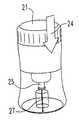
도 1은 그 사용 전의 본 발명의 지연 기구를 갖는 자동 주사 장치의 사시도이다.
도 2는 니들 커버가 도시되어 있지 않고 개략적으로 도시된 니들 주사기가 더 용이하게 관찰 가능한 도 1과 유사한 개략 사시도이다.
도 3은 상기 장치가 작동된 후의 그리고 주사기의 니들이 사용자의 피부를 관통하도록 상기 장치로부터 연장되는 사용 중의 어떤 시기의 도 2와 유사한 개략 사시도이다.
도 4는 상기 장치가 주사를 완료하고 하우징 내로 주사기의 니들을 후퇴시킨 후의 도 3과 유사한 개략 사시도이다.
도 5는 그 로킹 해제 및 사용 전의 도 1의 자동 주사 장치의 길이 방향 단면도이다.
도 6a, 6b, 6c 및 6d는 각각 도 1의 장치의 다른 구성 요소와 별개로 도시되어 있는 하우징 본체의 사시도, 측면도, 평면도 및 길이 방향 단면도이다.
도 7a, 7b, 7c, 7d 및 7e는 각각 다른 장치 구성 요소와 별개로 도시되어 있는 플런저 요소의 평면 사시도, 저면 사시도, 정면도, 측면도 및 저면도이다.
도 8a 및 8b는 각각 다른 장치 구성 요소와 별개로 도시되어 있는 하우징 기부 판의 평면 사시도 및 길이 방향 단면도이다.
도 9a, 9b, 9c, 9d 및 9e는 각각 다른 장치 구성 요소와 별개로 도시되어 있는 셔틀 부재의 평면 사시도, 제1 측면도, 제2 측면도, 길이 방향 단면도 및 평면도이다.
도 10a, 10b, 10c 및 10d는 각각 다른 장치 구성 요소와 별개로 도시되어 있는 주사기 지지 부재의 사시도, 측면도, 길이 방향 단면도 및 평면도이다.
도 11a 및 도 11b는 각각 다른 장치 구성 요소와 별개로 도시되어 있는 셔틀 클립 요소의 사시도 및 평면도이다.
도 12a, 12b, 12c, 12d 및 12e는 각각 다른 장치 구성 요소와 별개로 도시되어 있는 지연 요소 또는 종동기의 사시도, 제1 측면도, 제2 측면도, 제1 길이 방향 단면도 및 제2 길이 방향 단면도이다.
도 13a, 13b 및 13c는 각각 다른 장치 구성 요소와 별개로 도시되어 있는 하우징 중심 로드(housing center rod)의 사시도, 제1 측면도 및 제2 측면도이다.
도 14는 다른 장치 구성 요소와 별개로 도시되어 있는 종동기를 편의시키는 스프링의 측면도이다.
도 15는 사용을 위해 로킹 해제되기 전에 도시되어 있는 도 1의 장치의 길이 방향 단면도이다.
도 16은 종동기가 플런저 요소로부터 회전 방향으로 로킹 해제될 때의 동작의 단계에서의 도 14의 장치의 길이 방향 단면도이다.
도 17은 그 주사기 니들이 후퇴 위치에서 확실하게 로킹된 상태로 사용이 완료된 후의 도 14의 장치의 길이 방향 단면도이다.
대응 도면 부호가 여러 개의 도면 전체에 걸쳐 대응 부품을 표시하고 있다. 도면들이 본 발명의 하나의 실시예를 나타내지만, 도면은 일정한 비율로 작성될 필요가 없고, 어떤 특징이 본 발명을 더 양호하게 예시 및 설명하도록 도면들 중 일부에서 과장 또는 생략될 수 있다.BRIEF DESCRIPTION OF THE DRAWINGS The above-mentioned and other advantages and objects of the present invention and the manner of achieving them will become more apparent and the invention itself will be better understood Will be.
1 is a perspective view of an automatic scanning apparatus having a delay mechanism according to the present invention before use thereof.
Fig. 2 is a schematic perspective view similar to Fig. 1 in which a needle cover is not shown and the needle syringe shown schematically is more easily viewable.
Figure 3 is a schematic perspective view similar to that of Figure 2 at any time during use, after the device is actuated and extending from the device so that the needle of the syringe penetrates the skin of the user.
Figure 4 is a schematic perspective view similar to Figure 3 after the device has completed the injection and has retracted the needle of the syringe into the housing.
Figure 5 is a longitudinal cross-sectional view of the automatic scanning device of Figure 1 before its unlocking and use.
6A, 6B, 6C and 6D are a perspective view, a side view, a plan view and a longitudinal cross-sectional view, respectively, of a housing body which is shown separately from the other components of the apparatus of FIG.
Figures 7a, 7b, 7c, 7d and 7e are a plan perspective view, a bottom perspective view, a front view, a side view, and a bottom view, respectively, of a plunger element that is shown separately from other device components.
8A and 8B are a plan perspective view and a longitudinal section view, respectively, of the housing base plate shown separately from the other device components.
Figures 9a, 9b, 9c, 9d and 9e are a plan perspective view, a first side view, a second side view, a longitudinal sectional view and a plan view, respectively, of a shuttle member which is shown separately from the other device components.
Figures 10a, 10b, 10c and 10d are perspective, side elevation, longitudinal section and plan view, respectively, of the syringe support member shown separately from the other device components.
11A and 11B are a perspective view and a plan view of a shuttle clip element which is shown separately from the other device components.
Figures 12a, 12b, 12c, 12d and 12e are respectively a perspective view, a first side view, a second side view, a first longitudinal section and a second longitudinal section of a delay element or a follower, respectively, .
Figures 13a, 13b and 13c are perspective, first side and second side views, respectively, of a housing center rod, shown separately from other device components.
Figure 14 is a side view of a spring that biases the follower shown separately from other device components.
Figure 15 is a longitudinal cross-sectional view of the apparatus of Figure 1 shown before being unlocked for use.
Figure 16 is a longitudinal cross-sectional view of the device of Figure 14 at the stage of operation when the follower is unlocked in the rotational direction from the plunger element.
Fig. 17 is a longitudinal cross-sectional view of the device of Fig. 14 after the syringe needle has been used in a securely locked position in the retracted position.
Corresponding reference numerals denote corresponding parts throughout the several drawings. Although the drawings illustrate one embodiment of the invention, the drawings are not necessarily to scale and certain features may be exaggerated or omitted in some of the drawings to better illustrate and describe the invention.
도 1에서, 본 발명의 지연 기구를 갖는 자동 주사 장치(20)의 제1 실시예의 사시도가 도시되어 있다. 도 2-4에서, 단순한 니들형 주사기를 갖고 사용 시에 주사 중에 삽통 및 관통되는 도시되지 않은 그 니들 커버를 갖는 장치(20)가 개략적으로 도시되어 있다. 도 2에서, 장치(20)는 로킹 해제 각도 위치로 하우징 본체(34)에 대해 화살표 23에 의해 표시된 것과 같이 안전 슬리브(32)를 회전시킴으로써 로킹 해제되는 것으로 도시되어 있다. 장치 로킹 해제 후에 그리고 트리거 버튼(21)이 화살표 24에 의해 표시된 것과 같이 압박될 때에, 장치(20)의 니들형 주사기(25)는 주사기(25)의 주사 니들(27)이 도 3에 도시된 것과 같이 장치 하우징의 저부 단부를 넘어 돌출되어 사용자의 피부를 관통하도록 하향으로 자동적으로 구동된다. 상기 장치는 그 다음에 니들(27)을 통해 주사기(25)의 의약 내용물을 자동적으로 즉 추가의 사용자 동작 없이 주사하도록 진행되고, 그 후에 주사기는 니들(27)이 도 4에 도시된 것과 같이 하우징 내로 복귀되도록 화살표 29에 의해 표시된 것과 같이 자동적으로 후퇴된다. 장치(20) 내의 본 발명의 지연 기구는 니들형 주사기가 후퇴되기 전에 의약 내용물이 적절하게 분배되는 것을 보증하는 동작을 하는 것을 돕는다. 지연 기구는 또한 주사기 및 다른 장치 구성 요소에서의 축 방향 공차를 보상하는 수단으로서 유용하다.1, there is shown a perspective view of a first embodiment of an
본 발명의 지연 기구는 여기에서 설명된 장치(20)에서 유리한 적용 분야를 찾은 것으로 예시되어 있지만, 이러한 적용 분야는 단지 예시이고 제한인 것으로 의도되지 않는다. 본 발명의 지연 기구는 그 이익이 요구되는 많은 상이하게 구성된 자동 주사 장치에서 사용될 수 있다.While the delay mechanism of the present invention is illustrated as having found an advantageous application in the
도 1 및 도 5를 재차 참조하면, 장치(20)는 상기 장치의 동작 구성 요소가 동작 가능하게 배치되는 외부 하우징(30)을 포함한다. 하우징의 상부 또는 원위 단부에는 그로부터 축 방향으로 돌출되는 버튼(21)이 있다. 안전 슬리브(32)가 사용자 또는 사용자를 돕는 누군가에 의해 압박되는 버튼(21)을 로킹 해제하도록 회전가능하게 배향될 때에, 압박된 버튼(21)은 장치(20)의 자동 동작 기능을 작동시키거나 시작하도록 플런저 요소(230)와 결합 해제되는 도 5에 도시된 하우징 내에서의 로크 링(lock ring)(140)의 회전을 가능케 한다. 상기 장치를 위한 안전 슬리브(32) 및 트리거 조립체는 출원 제61/782929호로서 2013년 3월 14일자로 미국 특허 상표청에 출원된 임시 특허 출원에 그리고 본 건과 동일하게 나열된 발명자를 갖고 본 출원과 동일한 날짜로 수리 관청으로서의 미국 특허 상표청에 출원되고 "자동 주사 장치를 위한 트리거 조립체(Trigger Assembly for an Automatic Injection Device)"의 발명의 명칭을 갖는 국제 특허 출원에 추가로 기재되어 있고, 이들 출원의 양쪽 모두의 전체 개시 내용은 참조로 여기에 합체되어 있다.Referring again to Figures 1 and 5, the
여기에서 사용되는 것과 같이, 원위 및 근위는 상기 장치가 주사 부위에서의 사용을 위해 배향될 때에 이러한 주사 부위에 대한 축 방향 위치를 말하고, 그에 의해 예컨대 하우징의 근위 단부는 이러한 주사 부위에 가장 근접한 하우징 단부를 말한다.Distal " and " proximal ", as used herein, refers to an axial position relative to such an injection site when the device is oriented for use at the injection site, whereby the proximal end of the housing, for example, End.
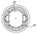
하우징(30)의 축 방향 높이는 안전 슬리브(32), 본체(34) 및 기부 판(35)에 의해 형성된다. 본체(34)는 도 6a-6d에 추가로 도시되어 있다. 본체(34)는 기부 부분(37) 및 포위 슬리브 부분(38)으로써 2개 부분 성형 공정으로부터 형성된다. 기부 부분(37)은 주사기 내용물의 관찰을 가능케 하도록 투명한 플라스틱 재료로 제조되고, 슬리브 부분(38)은 불투명한 플라스틱 재료로부터 제조된다. 슬리브 부분(38) 위에서, 기부 부분(37)의 상부 영역(41)은 디스크 부분(42)을 포함하고, 안전 슬리브(32) 및 버튼(21)을 장착하도록 구성된다. 본체(34)의 반경 방향 리세스형 저부 영역(43)이 중심 개구를 한정하고, 외부 나사산(45)이 제공된다.The axial height of the
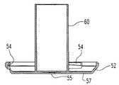
도 8a 및 8b에 추가로 도시되어 있는 하우징 기부 판(35)은 기부 부분(37)과 동일한 투명한 재료로 제조된다. 기부 판(35)의 림(rim)(52)은 본체(34)에 기부 판(35)을 확실하게 부착하도록 나사산(45)과 결합되는 54에서 그 내주연부를 따라 나사산 결합된다. 기부 판이 본체로부터 나사 결합 해제되지 않을 것을 보증하는 기부 판(35)과 본체(34) 사이의 포지티브 로킹 디텐트 특징부(positive locking detent feature)가 또한 제공될 수 있다. 주사기 니들이 사용 중에 하우징으로부터 외부로 그리고 그 다음에 그 내로 재차 이동되는 기부 판(35)의 디스크형 기부(57) 내의 작은 중심 구멍(55)이 기부(57)로부터 원위 방향으로 연장되는 튜브 부분(60)에 의해 링형으로 포위된다.The
하우징은 본체(34)의 중심 내의 하우징 디스크 부분(42)으로부터 현수되는 도 5에 도시된 로드형 부분 또는 샤프트(62)에 의해 형성되는 중심 내부 부분을 또한 포함한다. 제조 및 조립을 용이하게 하기 위해, 샤프트(62)는 별개로 형성되고 그 다음에 하우징 본체(34)에 대해 항상 회전 및 축 방향으로 고정되도록 예컨대 도시된 체결구(64)로써 견고하게 고정된다.The housing also includes a central interior portion formed by the rod-shaped portion or
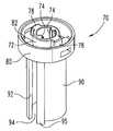
하우징 샤프트(62)는 도 12a-12e에 추가로 도시되어 있는 종동기 또는 지연 요소(70)를 지지한다. 지연 요소(70)는 1개의 강성 피스로서 형성되고, 다른 방식으로 개방된 중심(76) 내로 반경 방향 내향으로 연장되는 한 쌍의 대면 리브 또는 키(74)를 갖는 중심 칼라(central collar)(72)를 포함한다. 키(74)는 칼라(72)의 전체 축 방향 길이만큼 연장된다. 2개의 탭 또는 이어(tab or ear)(78)가 칼라의 원위 단부에서 칼라(72)의 직경 부분으로부터 반경 방향 외향으로 돌출된다. 링형 감쇠 핀(ring-shaped damping fin)(80)은 칼라(72)와 동심이다. 핀(80)은 핀(80)의 근위 단부와 칼라(72)의 중심 축 방향 영역 사이에서 연장되는 횡단 플랜지(82)에 의해 칼라(72)에 연결된다. 단일의 연속 핀이 제공되지만, 이것은 대체 실시예에서 상이한 형상 및 개수의 핀으로써 교체될 수 있다.The
2개의 구멍(84)이 플런저 요소(230)의 키(264)의 상부 단부를 수용하도록 180˚만큼 떨어져 중심 설정된 상태로 플랜지(82)를 통해 제공된다. 핀(80)을 통한 2개의 개구(86)가 탭(78)의 반경 방향 외향으로 직접적으로 그리고 구멍(84) 사이에 각도 방향으로 중심 설정된 상태로 제공된다. 개구(86)는 탭(78)의 성형을 위한 제조 중에 사용되고, 또한 감쇠 유체가 핀(80)의 양쪽 대향 반경 방향 측면(81, 83)으로 이동되게 하도록 기능한다.Two
한 쌍의 레그(leg)(90)가 플랜지(82)로부터 근위 방향으로 연장된다. 레그(90)는 칼라(72) 아래에 원통형 중공부(91)를 부분적으로 한정하도록 각도 방향으로 만곡된다. 각각의 레그(90)의 각도 방향 측면(92)은 강도를 위해 더 두껍게 제조되고, 직경 방향으로 대향되는 축 방향 연장 개구(94)를 제공하도록 다른 레그(90)의 양쪽 대향 측면으로부터 각도 방향으로 이격된다.A pair of
개구(94)는 플런저 요소 키(264)를 위한 키웨이로서 기능하고, 그 키결합 맞물림이 도시된 실시예에서 하우징 샤프트(62)에 대해 회전적으로 고정된 상태로 종동기(70)를 유지하여 플런저 요소(230)가 작동 후에 충분한 거리만큼 축 방향으로 이동될 때까지 주사기가 후퇴되는 다른 위치인 또 다른 위치를 향해 종동기가 이동되는 것을 방지하는 데 사용된다. 대체 실시예에서, 종동기는 플런저 요소에 키결합될 필요가 없고, 다른 방식으로 하우징 내에서 트랙을 따라 이동되는 것이 방지될 수 있고, 이러한 이동 방지는 축 방향으로 이동될 때에 플런저 요소에 의해 취소된다. 예컨대, 종동기가 하우징에 직접적으로 연결될 수 있거나, 래치 또는 스냅을 통해 셔틀 등의 하우징과 회전적으로 고정되거나 하우징과 회전적으로 고정되지만 하우징에 대해 축 방향으로 활주 가능한 로크 부재에 의해 이동되는 것이 차단되는 부분에 직접적으로 연결될 수 있다. 플런저 요소가 근위 방향으로 이동될 때에, 플런저 요소는 종동기와 래칭 해제 또는 스냅 해제되거나, 종동기를 차단하는 그 위치로부터 로크 부재를 이동시키고, 그에 의해 종동기가 그 다음에 하우징 트랙 상에서 자유롭게 이동된다. 이러한 대체 실시예는 국제 공개 제WO2011/109205호 및 제WO2008/112472호에 비추어 추가로 이해될 것이고, 이들 출원의 전체 개시 내용은 참조로 여기에 합체되어 있다.The opening 94 functions as a keyway for the
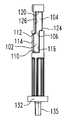
하우징 샤프트(62) 및 지연 요소(70)는 샤프트(62)에 대해 축 방향으로 그리고 회전 가능하게 지연 요소(70)의 이동을 안내하도록 키결합으로써 상보적으로 설계된다. 이러한 목적을 위해 그리고 도 13a-13c를 참조하면, 샤프트(62)는 축 방향으로 연장된 채널(106)에 의해 연결되는 한 쌍의 리세스 또는 키웨이 영역(102) 그리고 한 쌍의 리세스 또는 키웨이 영역(104)을 갖는 대체로 원통형의 본체(100)를 포함하고, 이들 모두는 키(74)를 근접하게 수용한다. 채널(106)에 의해 연결된 영역(102, 104)은 축 방향으로 긴 키(74)를 위한 트랙 또는 키웨이를 형성한다. 단지 1개의 이러한 키웨이가 필요하지만, 2개의 각도 방향으로 이격된 키웨이가 부품들을 균형시킨다. 단지 1개의 세트의 리세스 영역(102, 104) 및 채널(106)이 도 13b 및 13c에서 관찰 가능하지만, 디스크 섹션(132)을 제외하면 도 13b 및 13c에 도시된 이들 측면에 대향되는 샤프트(62)의 측면은 유사하다는 것이 이해될 것이다. 각각의 리세스 영역(102)은 그 영역의 전체 각도 방향 횡단부만큼 연장되는 저부 견부(110), 채널(106)이 그 영역 내로 개방되는 곳 이외의 전체 각도 횡단부만큼 연장되는 상부 견부(112), 견부(110, 112)를 횡단하는 축 방향으로 연장된 견부(114) 그리고 채널(106)로 이어지는 단부 견부(116)를 포함한다. 각각의 리세스 영역(104)은 채널(122) 이외의 그 영역의 전체 각도 횡단부만큼 연장되는 상부 견부(120), 채널(106)이 그 영역 내로 개방되는 곳 이외의 그 영역의 전체 각도 횡단부만큼 연장되는 저부 견부(124), 채널(106)로부터 계속되는 단부 견부(126) 그리고 저부 견부(124)로부터 채널(122)까지 축 방향으로 연장되는 정지 견부(128)를 포함한다. 각각의 리세스 영역(102)은 정확하게 종동기(70)의 회전 운동을 생성하도록 구성되는 것으로 도시되어 있지만, 각각 또는 양쪽 모두는 운동의 축 방향 성분을 또한 생성하도록 구성될 수 있고, 이것은 종동기가 리세스 영역(102) 내에서 이동되면서 회전 방향 및 축 방향의 양쪽 모두의 방향으로 이동되는 것을 의미한다.The
각각의 상부 견부(120)에는 그 각도 크기의 중간 섹션을 따라 도시되지 않은 노치(notch)가 제공될 수 있고, 이러한 노치는 조립 단계 중에 스프링-작동식 종동기를 보유하는 포획부로서 기능한다.Each
리세스 영역(102) 및 축 방향 채널(106)에 의해 형성되는 도시된 트랙은 트랙 내에 정사각형 조그(square jog)를 효과적으로 생성한다. 종동기 이동 중에, 리세스 영역(102)을 따라 이동되는 각각의 키(74)가 그 각각의 트랙의 정사각형 조그 내의 위치에 도달될 때에, 키(74)가 채널(106)을 따라 리세스 영역(102)으로 이동됨에 따라, 종동기의 감쇠되고 느린 회전이 종료되고, 그 다음에 종동기(70)의 감쇠되지 않고 급속한 이동이 일어난다. 이러한 급속한 이동은 거의 즉각적인 종동기 후퇴를 제공하고 그에 의해 성취되는 주사기 후퇴가 사용자에게 관찰 가능하게, 청취 가능하게 그리고 접촉 가능하게 명확해지게 한다.The illustrated track formed by the recessed
대체 실시예에서 그리고 종동기가 장치 사용 전의 그 회전 방향으로 로킹된 위치로부터 추가로 이동되기 전의 주사기 후퇴가 그 후퇴의 로킹을 수행하게 하는 위치로 이동될 때에 종동기를 안내하기 위해, 트랙은 그 길이의 모두 또는 일부를 따라 종동기의 점진적인 나선형 스위프(gradual helical sweep)를 생성하도록 형성될 수 있다.In an alternative embodiment and in order to guide the follower when the syringe retraction before the follower is further moved from its locked position in its rotational direction prior to use of the device is moved to a position to effect the locking of that retraction, May be formed to produce a progressive gradual helical sweep along all or part of the length.
리세스 영역(102)의 근위 방향으로 위치되는 샤프트(62)의 홈형 부분(130)은 장치 조립에서 사용되는 스텁(stub)(135)이 근위 방향으로 연장되는 디스크 섹션(132)에서 종료된다. 디스크 섹션(132)은 편의 부재(150)의 축 방향으로 돌출된 근위 단부 또는 팁(152)이 삽입되는 축 방향으로 배향된 개구(134)를 포함한다.The slotted
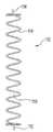
도 14에 가장 잘 도시된 편의 부재(150)는 샤프트(62)에 대해 회전 가능하게 그리고 또한 축 방향으로 종동기(70)를 편의시키도록 기능한다. 편의 부재(150)는 나선형으로 권취된 와이어(154)로 형성되는 원통형 스프링으로서 도시되어 있다. 스프링(150)은 이용 가능한 공간 내에서 적절한 비틀림 및 축 방향 힘을 제공하도록 선택되고, 선택은 요구되는 지연 등의 장치 동작 그리고 감쇠 화합물, 종동기 및 셔틀 구성 등의 협력 구성 요소의 설계에 의존한다. 이중 기능을 수행하도록 구성되는 금속 또는 플라스틱 만곡부 등의 다른 설계의 편의 부재가 도시된 단일의 금속 코일 스프링에 대해 대체될 수 있다. 대체 실시예에서 그리고 부품 개수가 증가될 것이지만, 단일의 편의 부재(150)가 축 방향 및 회전 방향 편의 기능을 수행하도록 2개 이상의 편의 부재로써 교체될 수 있거나, 캠 또는 나사산 표면을 통해 비틀림 프리로드(preload)를 제공하는 추가의 피스 또는 구동기와 결합되는 축 방향 스프링으로써 교체될 수 있다.14 best serves to bias the
스프링(150)의 내부 개구(156)는 샤프트(62)를 자유롭게 수용하고, 한편 스프링(150)의 외경부는 종동기(70)의 원통형 중공부(91) 내에 자유롭게 끼워진다. 스프링(150)의 축 방향으로 연장된 원위 팁(158)은 칼라(72)의 하부측 내에 형성되는 도시되지 않은 블라인드 포켓(blind pocket) 내에 삽입된다. 스프링(150)의 양쪽 대향 단부 코일은 칼라(72)의 하부측 그리고 샤프트 디스크 섹션(132)의 원위 표면에 대해 작용한다. 스프링(150)은 단부(158, 152)가 상호 교환 가능하도록 대칭이다.The
셔틀 부재(170)가 장치 하우징(30) 내에 지연 부재(70)에 의해 축 방향으로 보유된다. 도 9a-9e에 추가로 도시되어 있는 셔틀 부재(170)는 주사기 후퇴를 위해 셔틀을 형성하도록 셔틀 클립 요소(216)와 협력한다. 셔틀 부재(170)는 일편으로 성형되고, 플런저 요소(230)를 수용하는 한 쌍의 직경 방향으로 배치된 활형 슬롯(174) 그리고 장치 제조 조립에서 사용되는 한 쌍의 직경 방향으로 배치된 개구(176)를 포함하는 환형 판 부분(172)을 포함한다. 판 부분(172)의 중심에는 직립 칼라(180)가 있고, 이것은 칼라(180)의 원위 표면으로부터 근위 방향으로 리세스형으로 형성되는 중심 부분(182)을 링형으로 포위한다. 중심 부분(182)은 제조 조립 중에 종동기 칼라(72) 및 탭(78)의 삽입된 원위 단부를 그를 통해 수용하도록 성형되는 키결합 개구(184)를 한정한다. 이러한 조립 중에, 삽입된 칼라(72)의 회전은 셔틀 부재(170)가 장치 동작 전체에 걸쳐 종동기(70)에 대해 축 방향으로 고정되도록 중심 부분(182)이 칼라 탭(78)과 횡단 플랜지(82) 사이에 포획되게 한다. 한 쌍의 직경 방향으로 대향된 탭(188)이 칼라(180)로부터 반경 방향 외향으로 돌출되고, 셔틀 부재(170)에 대해 축 방향으로 로크 링(140)을 위치시키도록 기능한다.The
칼라(180)의 U자형 하부측(190)은 환형 중공부 또는 포켓(192)을 한정하고, 종동기(70)가 셔틀 부재(170)에 대해 회전될 때에 감쇠 유체를 위한 지지 표면을 제공한다.The U-shaped
나이 탄화불소 젤(Nye fluorocarbon gel) 880으로서 나이 루브리컨츠(Nye Lubricants)로부터 이용 가능한 테플론으로써 걸쭉해진 실리콘 그리스(silicone grease) 등의 도 5에서의 감쇠 화합물 또는 유체(195)가 환형 포켓(192)을 충전한다. 종동기 핀(80)은 감쇠 화합물(195)이 핀의 반경 방향 내향 및 외향으로 배치되도록 중공부(192) 내에 끼워지고, 그에 의해 종동기 핀(80)이 동작 중에 이러한 회전에 저항을 제공하는 점성 감쇠 유체로써 칼라 하부측(190)에 대해 회전되려고 할 때에 감쇠 또는 지연 효과를 가져온다. 상이한 성질을 갖는 다른 화합물이 통상의 기술자에 의해 선택될 수 있다.The dampening compound or
나아가, 유체 충전 포켓 그리고 각각 셔틀 부재 및 종동기 상에서 그 내에 삽입되는 핀의 위치 설정은 대체 실시예에서 각각 종동기 및 셔틀 부재로 스위칭될 수 있다.Furthermore, the positioning of the fluid fill pocket and the pins inserted into the shuttle member and the follower, respectively, may be switched to the shuttle member and the shuttle member, respectively, in an alternative embodiment.
셔틀 부재(170)는 반경 방향으로 만곡되고 환형 판 부분(172)으로부터 근위 방향으로 연장되는 2개의 레그(200)를 추가로 포함한다. 레그(200)는 플런저 편의 스프링(205)의 원위 단부가 바로 인접되는 환형 표면을 판 부분(172)의 돌출 영역(202)이 제공하도록 판 부분(172)의 외부 반경 방향 주연부로부터 이격된다. 한 쌍의 도시되지 않은 직경 방향으로 대향된 현수 후크는 스프링(205)이 셔틀 부재(170) 상에 중심 설정된 상태로 남아 있는 것을 보증하도록 판 부분(172)의 외부 반경 방향 주연부 상에 제공될 수 있다. 각각의 레그(200)의 축 방향으로 연장된 각도 방향 측면(204)은 플런저 요소 레그(232)가 끼워지는 축 방향으로 연장되고 직경 방향으로 대향된 개구(206)를 제공하여 셔틀 부재(170)에 대해 플런저 요소(230)를 회전적으로 고정하도록 다른 레그(200)의 양쪽 대향 측면으로부터 각도 방향으로 이격된다. 레그(200)는 원통형 중공부(203)를 부분적으로 한정하도록 반경 방향으로 만곡된다. 레그(200)의 내부 반경 방향 표면(207)은 주사기가 셔틀 부재(170) 내에서 상향으로 이동되는 것을 방지하도록 정지부로서 기능하는 길이 방향으로 연장된 리브(209)를 포함한다.The
레그(200)의 외부 반경 방향 주연부의 하부 영역(212)은 도 11a 및 11b에 추가로 도시되어 있는 클립 요소(216)의 탄성 플랜지(218)를 수용하도록 214에서 리세스형으로 형성된다. 클립 요소(216)는 단일 편의 스테인리스강으로 제조된다. 플랜지(218)는 셔틀 부재(170)로써 클립 요소(216)를 견고하게 고정하여 이들이 단일의 부품으로서 작용하도록 레그(200)를 탄성적으로 파지한다. 플랜지(218)는 중심 개구(222)를 갖는 링형 기부(220)까지 연장된다. 개구(222)는 주사기 배럴(352)이 그를 통해 끼워지게 하지만 원위 플랜지(354)가 그를 통해 끼워지지 않게 하는 크기로 형성된다. 링형 기부(220)는 주사기 플랜지(354)와 결합되는 크기로 형성되고, 튜브 부분(60)의 상부 부분으로부터 축 방향으로 제거된 상태로 체류하도록 설계된다. 기부(220) 내의 노치(223)가 아래에서 추가로 설명되는 슬리브 암(318)의 통과를 허용한다.The
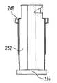
사용 중에 니들 삽입 및 의약 분배의 양쪽 모두를 구동하도록 하우징(30) 내에서 축 방향으로 이동되는 플런저 요소(230)가 도 7a-7e에 추가로 도시되어 있다. 플런저 요소(230)는 레그의 근위 단부에서 외향으로 향한 플랜지형 단부(236)를 갖는 축 방향으로 연장된 레그(232)를 포함한다. 판 부분(248) 위의 레그(232)의 상부 영역(240)은 셔틀 판 부분(172)의 슬롯(174) 내에 삽입되는 크기 및 형상으로 형성된다. 상부 영역(240)은 로크 링(140)의 상보성 부분과 결합되는 캠 표면(244)을 포함한다. 장치(20)의 트리거 조립체가 캠 표면(244)으로부터 로크 링 부분을 결합 해제하도록 사용자에 의해 작동될 때까지, 플런저 요소(230)는 효과적으로 래칭되어 압축된 스프링(205)의 편의력 하에서 근위 방향으로 축 방향으로 이동되는 것이 방지된다.7A-7E, the
플런저 요소(230)는 레그(232)를 횡단하는 중심 판 부분(248)을 또한 포함한다. 부분적으로 폐쇄된 저부 단부(252)를 갖는 원통형 튜브(250)가 플런저 레그(232) 사이에서 판 부분(248)으로부터 현수된다. 저부 단부(252)는 장치 주사기(350)의 밀봉 피스톤 또는 플런저(356)와 직접적으로 결합된다. 튜브(250)는 주사기(350)의 배럴(352) 내로의 그 삽입을 허용하는 횡단면을 갖는 크기로 형성된다. 튜브(250)의 외부 반경 방향 주연부와 레그(232)의 내부 반경 방향 주연부 사이의 반경 방향 간극(254)은 플런저 요소 튜브(250)가 주사기 배럴(352) 내로 삽입될 때에 주사기(350)의 상부 크기-도시된 예에서는 주사기(350)의 플랜지(354) 및 인접한 배럴(352)-을 수용하는 크기로 형성된다.The
튜브(250)의 중공 내부(256)는 장치 동작까지 그 내에 종동기 레그(90)를 수납하는 크기로 형성된다. 단부(252) 내의 4개의 개구(260)는 종동기 레그(90) 상의 연장 탭 또는 연장부(95)가 초기에 끼워지는 간극을 제공하고, 이러한 연장부는 플런저 요소의 축 방향 이동의 더 긴 부분에 대해 결합된 상태로 종동기(70) 및 셔틀 요소(230)를 유지하여야 한다. 중공 내부(256)의 상부 영역은 한 쌍의 내향으로 돌출된 키(264)에 의해 중단된다. 키(264)는 종동기(70)가 플런저 요소(230)에 대해 튜브(250) 내로부터 외부로 상승되도록 플런저 요소(230)가 주사 중에 이동될 때에 키(264)가 개구(94) 아래로 낙하될 때까지 종동기(70)가 플런저 요소(230)에 대해 회전되는 것을 방지하도록 종동기(70)의 개구(94) 내에 끼워진다. 키(264)는 종동기(70)의 간극 구멍(84) 내로 끼워지도록 판 부분(248) 위에서 연장된다. 키(264)는 플런저 요소의 축 방향 이동의 더 긴 부분에 대해 결합된 상태로 종동기(70) 및 셔틀 요소(230)를 유지하도록 판 부분(248) 위에서 연장된다.The
플런저 요소(230)는 셔틀 부재 레그(200)와 플런저 요소 레그(232)의 상호 끼움으로 인해 장치(20) 내에서 항상 셔틀 부재(170)와 회전 가능하게 키결합된다. 돌출된 리브 부분(280)은 플런저 레그 측면(204)과 결합되는 레그(232)의 부분이다. 리브 부분(280)은 장치 조립 중에 슬리브 암(318)이 지나가도록 반경 방향으로 감소된다.The
플런저 요소(230)는 도 10a-10d에 추가로 도시되어 있는 주사기 지지 부재(290)에 의해 그 축 방향 길이의 대부분을 따라 포위된다. 주사기 지지 부재(290)는 원위 단부(294)로부터 근위 단부(296)까지 연장되는 튜브형 본체 또는 슬리브(292)를 포함한다. 원위 단부(294)로부터 돌출되는 한 쌍의 직경 방향으로 대향된 플랜지(298)의 각각은 기부 부분(37)의 내부 표면(311) 상에 형성되는 수직으로 연장된 리브(308)를 통해 하우징 본체(34) 상에 제공되는 직경 방향으로 배열된 채널 또는 키웨이(304) 내에서 축 방향으로 활주되는 반경 방향 외향으로 돌출된 키(300)를 포함한다.The
슬리브(292)는 근위 단부(296) 근처의 내부 표면(312) 상에 제공되는 스프링-지지 셀프(spring-supporting shelf)(310)를 포함한다. 셀프(310)는 셀프(310)의 하부측을 따라 일련의 각도 방향으로 이격된 거싯(gusset)(314)에 의해 지지된다. 2개의 직경 방향으로 배열된 쌍의 지지 암(318)이 셀프(310) 아래의 내부 표면(312)으로부터 어떤 각도로 상향으로 돌출된다. 암(318)의 평탄화 상부 팁(320)은 주사기 배럴(352)의 플랜지(354)의 하부측과 결합되도록 슬리브(292)의 중공부(325) 내에서 이격된다. 암(318)은 상기 장치가 사용되기 전에 하우징(30) 내에 주사기(350)를 보유하도록 기능한다.
의약 주사를 구동하는 스프링(205)의 단부 코일은 셀프(310)의 상부 표면에 인접된다. 도 5에 가장 잘 도시된 것과 같이, 스프링(205)은 개재된 셀프(310)를 통해 플런저 요소 단부(236)에 대해 작용한다. 플런저 요소(230)의 플랜지형 단부(236)는 플런저 요소(230)가 주사기 지지 부재(290) 그에 따라 장치 하우징(30)과 회전적으로 고정되도록 암(318)의 하부 단부(325) 사이에 장착된다. 이러한 동작 연결은 주사기 지지 부재(290)가 플런저 요소(230)와 함께 장치(20)의 구동 플런저의 일부로서 작용한다는 것을 의미한다.The end coil of the
본 발명의 지연 기구(290)와 사용되는 의약 충전 니들형 주사기는 일반적으로 도 2-4에 도시된 것과 같은 구성을 갖는 적층형 니들 주사기 등의 다양한 주사기 설계들 중 하나일 수 있다. 상이한 니들 커버가 또한 채용될 수 있다. 장치(20)는 니들 커버(380)와 함께 니들 주사기(350)를 갖는 것으로서 도 5에 도시되어 있다. 주사기(350) 및 커버(380)는 그 출원의 전체 개시 내용이 참조로 여기에 합체되어 있는 국제 출원 제PCT/US2012/051702호에 기재되어 있는 개념적으로 유사한 주사기 설계에 비추어 추가로 이해될 것이다.A drug-filled needle syringe used with the
니들 주사기(350)는 그 원위 단부에서 반경 방향 외향으로 연장된 원주 방향 리브 또는 플랜지(354)를 갖는 배럴(352)을 포함한다. 플랜지(354) 아래의 탄성 중합체 링(355)이 셔틀 기부(220) 상에서의 플랜지(354)의 충격을 완충한다. 탄성 중합체 피스톤(356)은 의약 내용물이 배럴(352)의 상부 단부로부터 배출되는 것을 방지 하도록 배럴 내부와 함께 활주 가능하게 밀봉된다. 배럴(352)의 근위 단부에서의 칼라 부분(360)이 의약 저장조의 저부를 밀봉하는 관통 가능한 셉텀(septum)(364)을 형성하는 탄성 부분을 갖는 허브(hub)(362)와 연결된다.
니들 캐리어(370)가 이중-단부형 캐뉼러(double-ended cannula)(372)를 보유한다. 니들 캐리어(370)는 제한된 축 방향 위치들 사이에서 허브(362) 내에서 키결합되거나 회전적으로 고정된 방식으로 축 방향으로 이동 가능하다. 니들 캐리어(370)는 도 5에 개략적으로 도시되어 있지만, 허브(362)의 내부 표면 내에 제공되는 너브(bub)와 결합되는 그 상부 단부 상의 디텐트를 보유한 탄성 암을 갖는 것으로 도 15-17에 추가로 도시되어 있다. 캐뉼러(372)의 원위 팁(374)은 셉텀(364)을 관통하도록 되어 있고, 캐뉼러 근위 팁(376)은 커버(380)를 관통하여 사용자의 피부를 관통하도록 되어 있다.The
니들 커버(380)는 장치 사용 전에 캐뉼러(372)의 살균 상태를 유지하고, 단일의 기밀 탄성 중합체 피스로 제조된다. 커버(380)는 허브(362)에 장착되는 링 부분(382) 그리고 니들로 관통 가능한 단부 영역(386)을 갖는 삽통 본체(384)의 상부 단부에서의 힌징 영역(hinging region)(383)을 포함한다.The
장치(20)의 구성은 그 동작의 설명에 비추어 추가로 이해될 것이다. 상기 장치는 초기에 도 5 및 도 15에 도시된 것과 같이 구성되고, 이 때에 스프링(205)은 셔틀 부재(170)에 대해 플런저(230) 상에 편의력을 제공하도록 작용하는 압축 프리로딩 하에 있다. 이러한 편의력에도 불구하고, 플런저(230)는 셔틀 부재(170)에 장착된 로크 링(140)으로써 효과적으로 래칭되므로 셔틀에 대해 축 방향으로 근위 방향으로 이동될 수 없다. 스프링(150)은 하우징(30) 더 구체적으로 샤프트(62)에 대해 종동기(70)를 편의시키는 경향을 각각 갖는 비틀림 프리로딩 및 축 방향 프리로딩 하에 있다. 이러한 편의에도 불구하고, 종동기(70)는 리세스 영역(102) 내에서의 종동기 키(74)의 상호 끼움에 의해 키(74)가 상부 견부(112)에 인접되게 하고 키(264)가 종동기(70)의 개구(94) 내에 끼워짐으로써 수행되는 플런저 요소(230)와 종동기(70)의 키결합이 하우징 내에서의 종동기의 회전을 방지하므로 하우징 내에서 원위 방향으로 이동될 수 없다. 종동기(70) 그리고 보유된 셔틀 부재(170)는 종동기 키(74)가 샤프트 견부(110)에 인접되므로 근위 방향으로 이동될 수 없다.The configuration of the
주사를 가능케 하기 위해, 안전 슬리브(32)가 버튼(21)을 로킹 해제하도록 사용자 또는 사용자를 돕는 누군가에 의해 수동으로 회전되고, 장치(20)가 주사 부위 상에 위치된다. 트리거 조립체가 그 다음에 압박 버튼(21)에 의해 동작될 때에, 플런저 요소(230)가 하우징 내에서 근위 방향으로 스프링(205)에 의해 이동되도록 해제된다.To enable scanning, the
플런저 요소(230)는 주사기 플런저(356)와 그 튜브(250)의 저부 단부(252)의 직접적인 결합으로 인해 근위 방향으로 플런저(356)를 구동하고, 이것은 초기에 캐뉼러 팁(376)이 커버 영역(386)을 관통하게 하여 기부 판 개구(55)를 통해 연장되게 하고 그에 의해 사용자의 피부를 관통하도록 하향으로 배럴(352)을 이동시킨다. 커버(380)는 배럴(352)이 하향으로 이동될 때에 축 방향으로 삽통되기 시작한다. 캐뉼러 팁(374)은 허브(362) 내에 축 방향으로 보유되므로 셉텀(364)을 아직 관통하지 않고 있다.The
플런저 요소(230)가 스프링(205)에 의해 하향으로 계속하여 이동됨에 따라, 주사기 배럴(352)이 근위 방향으로 계속하여 구동되고, 이 때에 커버(380)가 계속하여 삽통된다. 니들 캐리어(370)가 하우징 기부(57)에 인접되고 이 때에 커버 영역(386)이 그 사이에 개재될 때에, 니들 캐리어(370)가 근위 방향으로 추가로 이동될 수 없고, 베럴(352)의 추가의 근위 방향 이동은 셉텀(364)이 니들 팁(374)에 의해 관통되도록 허브(360)가 니들 캐리어(370)에 대해 이동되게 한다.As the
플런저 요소(230)의 추가의 하향 전진은 링(355)에 의해 완충되는 배럴 플랜지(354)가 클립 요소 기부(220)에 인접될 때까지 근위 방향으로 배럴(352)을 계속하여 이동시키고, 이러한 시점에서 배럴(352)은 근위 방향으로 이동될 수 없고, 커버(380)는 완전히 삽통되고, 플런저 요소(230)의 추가의 근위 방향 이동은 튜브(250)가 배럴(352) 내로 추가로 삽입됨에 따라 배럴(352) 내에서 추가로 하향으로 플런저(356)를 구동하고, 그에 의해 주사기 내용물이 캐뉼러(372)를 통해 그리고 사용자의 피부 내로 가압되게 한다.The additional downward advancement of the
플런저 요소(230)가 스프링(205)의 편의 하에서 근위 방향으로 이동됨에 따라, 키(264)가 팁(95)으로부터 제거될 때까지 개구(94) 내에서 종동기 레그(90) 아래로 활주되고, 이러한 시점에서 종동기(70)는 플런저 요소(230)로부터 회전가능하게 로킹 해제된다. 이러한 로킹 해제는 전형적으로 플런저의 근위 방향 이동의 종료 직전에 일어나도록 설계될 것이지만, 지연 기구의 지연 효과를 위한 설계에 따라 더 일찍 일어날 수 있다. 도 16은 이러한 동작 시점에서의 장치(20)를 도시하고 있다.As the
회전 가능하게 로킹 해제될 때에, 종동기(70)가 편의 부재(150)의 비틀림 프리로딩에 의해 압박될 때에 리세스 영역(102) 내에서 각도 방향으로 활주되는 키(74)로써 샤프트(62) 주위에서 회전되기 시작한다. 이러한 종동기 회전은 또한 플런저 요소(230)에 대한 그 키결합 관계를 통해 하우징 내에 회전적으로 고정된 상태로 남아 있는 셔틀 부재(170)에 대해 수행된다. 종동기 핀(80)과 셔틀 칼라(180) 사이의 점성 감쇠 화합물(195)은 이러한 종동기 회전을 감쇠시키거나 그에 대한 저항력을 제공하고, 이러한 저항은 아래에서 설명되는 것과 같이 종동기가 원위 방향으로 이동되기 전에 시간의 경과를 가져오고, 이러한 시간 중에 남아 있는 의약이 주사기로부터 니들 팁(376)을 통해 적절하게 방출될 수 있다.The
스프링(150)에 의해 구동될 때의 샤프트(62)에 대한 종동기(70)의 회전은 종동기 키(74)가 단부 견부(116)에 인접될 때까지 계속되고, 이러한 시점에서 키(74)는 채널(106)과 정렬된다. 그 때에, 플런저 요소(230)는 주사기 배럴(352) 내로 주사기 플런저(356)를 완전히 이동시켜 적절한 투여량을 방출하도록 그 근위 방향 이동을 완료하고, 스프링(150)에 의해 제공되는 축 방향 힘 하에서, 종동기(70)는 그 다음에 키(74)가 상부 견부(120)에 인접될 때까지 채널(106)을 통해 그리고 리세스 영역(104) 내로 활주되도록 하우징(30) 내에서 원위 방향으로 구동된다. 이러한 종동기(70)의 원위 방향 이동은 동시에 또는 동일하게 원위 방향으로 셔틀 부재(170) 및 셔틀 클립 요소(216)를 이동시킨다. 클립 요소(216)가 이렇게 이동됨에 따라 그리고 플랜지(354)의 하부측과 클립 기부(220)의 그 결합으로 인해, 주사기(350)는 하우징(30) 내의 보호 위치로 주사 니들(372)의 근위부(376)를 후퇴시키도록 원위 방향으로 셔틀에 의해 반송된다.The rotation of the
니들 후퇴 후에, 추가의 종동기 회전이 후퇴된 니들의 로킹을 생성한다. 특히, 키(74)가 견부(120)에 인접될 때에, 키(74)가 리세스 영역(104) 내에 배치된다. 여전히 남아 있는 편의 부재(150)의 비틀림 프리로딩은 샤프트(62)에 대한 동일한 각도 방향으로의 종동기(70)의 회전을 재시작하고, 이 때에 키(74)는 리세스 영역(104) 내에서 각도 방향으로 활주된다. 키(74)가 정지 견부(128)에 인접될 때에, 종동기 회전이 정지된다. 상부 견부(120)가 위에서 설명된 것과 같은 종동기 포획 특징부를 제공하도록 노치형으로 형성되면, 종동기 회전은 그 대신에 키(74)가 이들 노치 내로 활주될 때에 정지된다. 하우징 디스크 부분(42)으로의 샤프트(62)의 조립 중에 체결구(64)에 의해 효과적으로 채널(122)이 키(74)로 통과 불가능하게 되므로, 키(74)는 샤프트(62)로의 종동기(70)의 조립 중에 사용되는 채널(122) 내로 계속하여 진행되지 않는다. 종동기(70) 그리고 그에 따라 셔틀 부재(170)를 포함하는 셔틀이 그 다음에 키(74)에 의한 견부(124)의 인접한 결합으로 인해 근위 방향으로 이동될 수 없기 때문에, 니들형 주사기(350)는 후퇴 위치에서 로킹된다. 이러한 시점에서, 장치(20)는 도 17에서와 같이 구성되고, 사용자는 그 다음에 정상 경로로 상기 장치를 배치하거나 그렇지 않으면 취급할 수 있다.After needle retraction, additional longitudinal synchronized rotation generates locking of the retracted needle. Specifically, when the key 74 is adjacent to the
본 발명은 양호한 설계를 갖는 것으로서 예시 및 설명되었지만, 본 발명은 본 발명의 사상 및 범주 내에서 변형될 수 있다. 예컨대, 본 발명의 지연 기구가 상이하게 성형된 부품을 가질 수 있거나, 대체의 트리거 등의 상이한 다른 구성 요소를 갖는 장치에서 사용될 수 있다. 나아가, 다양한 부품이 함께 키결합되는 방식 그리고 어떤 부품이 다른 부품에 직접적으로 키결합되는 사실이 대체 실시예에서 변화될 수 있다. 예컨대, 다양한 부품 상의 키 및 키웨이가 스위칭될 수 있거나, 셔틀이 예컨대 플런저 요소를 통해 간접적으로 키결합되는 대신에 회전적으로 고정되도록 하우징과 직접적으로 키결합될 수 있다. 더 나아가 그리고 설명된 플런저 요소가 배럴 내에서의 주사기 전진 그리고 또한 주사기 피스톤의 전진의 양쪽 모두를 구동하지만, 지연 기구는 이것이 결합되는 플런저 요소가 단지 배럴 내에서의 피스톤 전진을 구동하는 장치에서 채용될 수 있다. 더 나아가 그리고 감쇠 화합물이 도시된 실시예에서 셔틀과 종동기 사이에 직접적으로 제공되지만, 대체 실시예에서 그리고 이러한 종동기 및 셔틀 직접 감쇠 특징부 대신에 또는 그에 추가하여, 감쇠 특징부는 직접적으로 종동기와 하우징 사이에 제공될 수 있지만, 이것은 하우징에 대한 종동기의 축 방향 이동을 지연시킬 수 있고 그에 따라 주사기 축 방향 후퇴를 지연시킬 수 있다. 그러므로, 본 출원은 그 일반적인 원리를 사용하는 본 발명의 임의의 변화, 사용 또는 조정을 포함하도록 의도된다. 나아가, 본 출원은 본 발명이 속한 기술 분야에서 공지되거나 관례적인 실시 내에 속하는 것과 같은 본 발명으로부터의 이러한 이탈 사항을 포함하도록 의도된다.While the present invention has been illustrated and described as having a preferred design, the present invention may be modified within the spirit and scope of the present invention. For example, the delay mechanism of the present invention may have differently shaped components, or may be used in an apparatus having different and different components such as an alternate trigger. Furthermore, the manner in which the various components are keyed together and the fact that certain components are keyed directly to the other can be varied in alternative embodiments. For example, the keys and keyways on the various components can be switched, or the shuttle can be keyed directly to the housing such that it is rotatably fixed instead of being indirectly keyed, e.g., via the plunger element. Further and although the described plunger element drives both the advancement of the syringe in the barrel and also the advancement of the syringe piston, the delay mechanism is such that the plunger element to which it is engaged is only employed in a device that drives the piston advancement in the barrel . Further, and although the damping compound is provided directly between the shuttle and the tail in the illustrated embodiment, in alternative embodiments and in place of or in addition to such longitudinal and shuttle direct damping features, But this can delay the axial movement of the follower relative to the housing and thus delay the syringe axial retraction. This application is therefore intended to cover any variations, uses, or adaptations of the invention using its general principles. Furthermore, the present application is intended to cover such departures from the present invention as come within known or customary practice in the art to which this invention pertains.
Claims (25)
Translated fromKorean하우징에 대해 회전적으로 고정되고 후퇴를 위해 주사기와 결합되도록 구성되는 셔틀과;
제1 방향에 반대인 방향으로 상기 셔틀을 이동시키도록 구성되는 종동기로서, 상기 종동기는 하우징 상의 제1 위치로부터 하우징 상의 제2 위치로의 이동을 위해 하우징과 키결합되고, 상기 제2 위치는 상기 제1 위치로부터 제1 방향에 반대인 상기 방향으로 축 방향으로 이격되고, 상기 제2 위치는 상기 제1 위치로부터 회전 방향으로 이격되는, 종동기와;
상기 종동기의 회전을 감쇠시키도록 상기 종동기의 표면과 상기 셔틀 및 하우징 중 적어도 하나 사이에 있는 감쇠 화합물과;
상기 제1 위치로부터 상기 제2 위치로 상기 종동기를 압박하는 힘을 제공하는 적어도 1개의 편의 부재와;
주사를 위해 배럴 내에서 피스톤을 구동하여 주사 니들을 통해 의약을 가압하도록 구성되는 편의 플런저 요소로서, 상기 편의 플런저 요소는 제1 장소로부터 제2 장소로 하우징 내에서 제1 방향으로 편의되고, 상기 플런저 요소는 하우징에 대해 회전적으로 고정되는, 편의 플런저 요소
를 포함하고,
상기 종동기는 상기 플런저 요소가 상기 제1 장소에 있을 때에 상기 제1 위치로부터 상기 제2 위치를 향해 이동되는 것이 방지되고, 상기 종동기는 상기 플런저 요소가 상기 제1 장소로부터 상기 제2 장소로 이동될 때에 상기 적어도 1개의 편의 부재가 상기 제1 위치로부터 상기 제2 위치로 상기 종동기를 이동시키고 그에 의해 상기 셔틀을 이동시켜 주사 후에 하우징 내로 주사 니들을 후퇴시키도록 상기 제1 위치로부터 상기 제2 위치를 향해 자유롭게 이동되는,
지연 기구.In an automatic scanning device that includes a housing and a medical filling syringe having a barrel, a piston and a syringe needle and is operable to move the syringe in a first direction relative to the housing to extend the syringe needle beyond the housing,
A shuttle configured to be rotatably secured to the housing and configured to engage the syringe for retraction;
A follower configured to move the shuttle in a direction opposite to the first direction, the follower being keyed with the housing for movement from a first position on the housing to a second position on the housing, The second position being spaced apart from the first position in the rotational direction, and a second position being axially spaced from the first position in the direction opposite to the first direction;
An attenuation compound between the surface of the follower and at least one of the shuttle and the housing to attenuate the rotation of the follower;
At least one biasing member for providing a force for urging the follower from the first position to the second position;
A convenience plunger element configured to drive a piston in a barrel for injection to press medicament through a needle, wherein the convenience plunger element is biased in a first direction within the housing from a first position to a second position, The element comprises a plunger element, which is rotationally fixed relative to the housing,
Lt; / RTI >
Wherein the follower is prevented from moving from the first position toward the second position when the plunger element is in the first position and the follower causes the plunger element to move from the first position to the second position Wherein the at least one biasing member moves from the first position to the second position when moved so as to move the shuttle thereby retracting the needle from the first position into the housing after scanning, 2 position,
Delay mechanism.
하우징 내에서 제1 방향으로 주사기를 후퇴시키는 셔틀과;
종동기와;
제1 위치로부터 제2 위치로 하우징에 대해 상기 종동기를 이동시키는 수단으로서, 상기 종동기는 상기 종동기가 상기 제1 위치로부터 상기 제2 위치로 이동될 때에 상기 셔틀을 이동시켜 제1 방향으로 주사기를 후퇴시키도록 구성되는, 수단과;
상기 제1 위치로부터 상기 제2 위치로의 하우징에 대한 상기 종동기의 이동을 안내하는 상기 종동기 및 하우징 상의 수단과;
주사기로부터 의약을 가압하도록 구성되는 플런저와;
상기 플런저가 주사기로부터 의약을 가압하기 시작할 때까지 상기 종동기가 상기 제1 위치로부터 상기 제2 위치를 향해 회전되는 것을 방지하는 수단과;
상기 종동기가 상기 제1 위치로부터 상기 제2 위치를 향해 이동될 때에 상기 종동기의 회전 운동을 감쇠시키는 수단
을 포함하는 지연 기구.A delay mechanism for an automatic scanning device having a housing and a syringe,
A shuttle for retracting the syringe in a first direction within the housing;
Follower;
Means for moving the follower relative to the housing from a first position to a second position, the follower causing the shuttle to move in a first direction when the follower is moved from the first position to the second position, Means for retracting the syringe;
Means on the follower and housing for guiding movement of the follower to the housing from the first position to the second position;
A plunger configured to pressurize the medicament from the syringe;
Means for preventing the follower from rotating from the first position to the second position until the plunger begins to press the medicament from the syringe;
And means for attenuating the rotational motion of the follower synchronized when the follower is moved from the first position toward the second position
.
Applications Claiming Priority (3)
| Application Number | Priority Date | Filing Date | Title |
|---|---|---|---|
| US201361783007P | 2013-03-14 | 2013-03-14 | |
| US61/783,007 | 2013-03-14 | ||
| PCT/US2014/021485WO2014159017A1 (en) | 2013-03-14 | 2014-03-07 | Delay mechanism suitable for compact automatic injection device |
Publications (1)
| Publication Number | Publication Date |
|---|---|
| KR20150119092Atrue KR20150119092A (en) | 2015-10-23 |
Family
ID=50349965
Family Applications (1)
| Application Number | Title | Priority Date | Filing Date |
|---|---|---|---|
| KR1020157024628ACeasedKR20150119092A (en) | 2013-03-14 | 2014-03-07 | Delay mechanism suitable for compact automatic injection device |
Country Status (13)
| Country | Link |
|---|---|
| US (1) | US9925337B2 (en) |
| EP (1) | EP2968766B1 (en) |
| JP (1) | JP6227109B2 (en) |
| KR (1) | KR20150119092A (en) |
| CN (1) | CN105025958A (en) |
| AU (1) | AU2014241449A1 (en) |
| BR (1) | BR112015020017A2 (en) |
| CA (1) | CA2899558A1 (en) |
| EA (1) | EA201591482A1 (en) |
| ES (1) | ES2927108T3 (en) |
| HK (1) | HK1212641A1 (en) |
| WO (1) | WO2014159017A1 (en) |
| ZA (1) | ZA201505514B (en) |
Cited By (2)
| Publication number | Priority date | Publication date | Assignee | Title |
|---|---|---|---|---|
| KR102412806B1 (en)* | 2021-08-27 | 2022-06-23 | 김성우 | Apparatus for injecting liquid medicine |
| US11554215B2 (en) | 2017-06-08 | 2023-01-17 | Novartis Ag | Injection device and injection solution transferring system |
Families Citing this family (30)
| Publication number | Priority date | Publication date | Assignee | Title |
|---|---|---|---|---|
| US9675754B2 (en) | 2012-10-24 | 2017-06-13 | Nuance Designs, LLC | Autoinjector |
| KR20150119092A (en)* | 2013-03-14 | 2015-10-23 | 일라이 릴리 앤드 캄파니 | Delay mechanism suitable for compact automatic injection device |
| MX388536B (en)* | 2014-05-07 | 2025-03-20 | Amgen Inc | AUTO-INJECTOR WITH SHOCK-REDUCING ELEMENTS. |
| JP6618486B2 (en)* | 2015-01-27 | 2019-12-11 | テルモ株式会社 | Sensor insertion device and sensor insertion device set |
| US10758677B2 (en) | 2015-04-24 | 2020-09-01 | Shl Medical Ag | Drive mechanism |
| CN113181477B (en) | 2015-06-04 | 2023-07-14 | 麦迪麦珀医疗工程有限公司 | Cartridge insertion for drug delivery device |
| FR3036965B1 (en) | 2015-06-05 | 2021-10-01 | Aptar France Sas | AUTOINJECTOR |
| FR3036966B1 (en)* | 2015-06-05 | 2021-10-01 | Aptar France Sas | AUTOINJECTOR |
| CA3027884A1 (en)* | 2015-06-15 | 2016-12-22 | Nuance Designs Of Ct, Llc | Autoinjector |
| CH711240A2 (en)* | 2015-06-23 | 2016-12-30 | Tecpharma Licensing Ag | Auto injection device. |
| CN109152883B (en)* | 2016-05-18 | 2020-12-01 | 艾斯曲尔医疗公司 | Drug delivery mechanism for drug delivery devices |
| CN109310831B (en)* | 2016-06-02 | 2021-11-23 | 西医药服务以色列有限公司 | Three position needle retraction |
| US10549044B2 (en) | 2016-06-09 | 2020-02-04 | Becton, Dickinson And Company | Spacer assembly for drug delivery system |
| US10792432B2 (en) | 2016-06-09 | 2020-10-06 | Becton, Dickinson And Company | Drive assembly and spacer for drug delivery system |
| JP7059251B2 (en) | 2016-08-01 | 2022-04-25 | ウェスト ファーマ サービシーズ イスラエル リミテッド | A spring that prevents the door from closing halfway |
| GB201701935D0 (en) | 2017-02-06 | 2017-03-22 | Owen Mumford Ltd | Medicament delivery devices |
| EP3630226A1 (en) | 2017-05-30 | 2020-04-08 | West Pharma. Services Il, Ltd. | Modular drive train for wearable injector |
| JP7200134B2 (en) | 2017-06-08 | 2023-01-06 | アムジエン・インコーポレーテツド | Torque driven drug delivery device |
| EP3651833B1 (en)* | 2017-07-12 | 2023-11-22 | Fresenius Vial SAS | Pump device having a holding device for receiving a syringe |
| CN111163817B (en)* | 2017-09-21 | 2022-04-01 | 西部制药服务有限公司(以色列) | Needle insertion mechanism for syringe |
| US11452821B2 (en) | 2017-10-12 | 2022-09-27 | Eli Lilly And Company | Needle shield puller for drug delivery system |
| JP7111809B2 (en) | 2017-10-16 | 2022-08-02 | ベクトン・ディキンソン・アンド・カンパニー | Spacer assembly for drug delivery device |
| JP7402799B2 (en) | 2017-12-22 | 2023-12-21 | ウェスト ファーマ サービシーズ イスラエル リミテッド | Syringes available with different cartridge sizes |
| KR102580064B1 (en)* | 2018-02-16 | 2023-09-20 | 벡톤 디킨슨 프랑스 | Medical injection device for supporting a medical container filled with a pharmaceutical composition |
| CN108434556A (en)* | 2018-05-23 | 2018-08-24 | 苏州鹏烨医疗科技有限公司 | Injection pen |
| KR20250127186A (en)* | 2018-10-15 | 2025-08-26 | 암젠 인크 | Drug delivery device having damping mechanism |
| CA3132163A1 (en) | 2019-03-15 | 2020-09-24 | Eli Lilly And Company | Automatic injection system |
| EP4426399A4 (en)* | 2021-11-01 | 2025-10-15 | Becton Dickinson Co | ALARM INDICATOR FOR A DRUG DELIVERY DEVICE |
| JP2025025364A (en)* | 2023-08-09 | 2025-02-21 | 大成化工株式会社 | Injection Device |
| KR102810349B1 (en)* | 2024-09-23 | 2025-05-19 | 장원재 | Automatic injector with drug injection dosage control function |
Family Cites Families (69)
| Publication number | Priority date | Publication date | Assignee | Title |
|---|---|---|---|---|
| FR1078911A (en) | 1949-08-17 | 1954-11-24 | Automatic hypodermic syringe and its ampoule | |
| US4561856A (en) | 1983-08-18 | 1985-12-31 | Cochran Ulrich D | Infusion pump |
| US4744786A (en) | 1986-06-17 | 1988-05-17 | Cordis Corporation | Infusion pump |
| CH684086A5 (en) | 1987-08-28 | 1994-07-15 | Ferag Ag | Transport device for printed products and using the same. |
| AU652122B2 (en) | 1989-05-04 | 1994-08-18 | Western Medical Products Pty. Limited | A syringe |
| DE69024815T2 (en) | 1989-09-18 | 1996-05-23 | Robb Pascal Patent Pty. Ltd., Alderley, Queensland | SYRINGE |
| DK0440846T3 (en) | 1990-02-07 | 1993-07-12 | Vetter & Co Apotheker | Double chamber syringe and application method |
| US5393301A (en) | 1992-10-05 | 1995-02-28 | Retrax, Inc. | Retractable syringe |
| GB9111600D0 (en) | 1991-05-30 | 1991-07-24 | Owen Mumford Ltd | Improvements relating to injection devices |
| US5167304A (en) | 1991-10-15 | 1992-12-01 | Allied-Signal Inc. | Drum brake torsion/compression strut spring |
| US5150933A (en) | 1991-10-29 | 1992-09-29 | General Motors Corporation | Latch having torsion spring leg and leaf spring leg |
| US5346480A (en) | 1992-12-14 | 1994-09-13 | Q-Med, Inc. | Syringe with retractable needle |
| US5540664A (en) | 1993-05-27 | 1996-07-30 | Washington Biotech Corporation | Reloadable automatic or manual emergency injection system |
| ES2070782B1 (en) | 1993-11-05 | 1995-12-16 | Vita Invest Sa | IMPROVEMENTS IN SELF-INJECTABLE EQUIPMENT. |
| CA2135706C (en) | 1993-11-15 | 1999-06-15 | Walter E. Cover | Retractable-needle cannula insertion set with refinements to better control leakage, retraction speed, and reuse |
| FR2715071B1 (en) | 1994-01-17 | 1996-03-01 | Aguettant Lab | Automatic drug injector. |
| US5514097A (en)* | 1994-02-14 | 1996-05-07 | Genentech, Inc. | Self administered injection pen apparatus and method |
| JP3568959B2 (en) | 1995-03-07 | 2004-09-22 | イーライ・リリー・アンド・カンパニー | Reusable dosing device |
| GB9612724D0 (en) | 1996-06-18 | 1996-08-21 | Owen Mumford Ltd | Improvements relating to injection devices |
| GB9714948D0 (en) | 1997-07-16 | 1997-09-17 | Owen Mumford Ltd | Improvements relating to injection devices |
| DE29801168U1 (en) | 1998-01-24 | 1999-08-12 | Medico Dev Investment Co | Injection device |
| GB9808408D0 (en) | 1998-04-18 | 1998-06-17 | Owen Mumford Ltd | Improvements relating to injection devices |
| DE19819409A1 (en) | 1998-04-30 | 1999-11-11 | Schering Ag | Injection device |
| DE19821933C1 (en) | 1998-05-15 | 1999-11-11 | Disetronic Licensing Ag | Device for administering an injectable product |
| SE9803662D0 (en) | 1998-10-26 | 1998-10-26 | Pharmacia & Upjohn Ab | autoinjector |
| GB9903475D0 (en) | 1999-02-17 | 1999-04-07 | Owen Mumford Ltd | Improvements relating to injection devices |
| US6368303B1 (en) | 1999-10-15 | 2002-04-09 | Becton, Dickinson And Company | Retracting needle syringe |
| US6475194B2 (en) | 2000-04-05 | 2002-11-05 | Gem Plastics, Inc. | Safety syringe |
| US6387078B1 (en) | 2000-12-21 | 2002-05-14 | Gillespie, Iii Richard D. | Automatic mixing and injecting apparatus |
| US20030105430A1 (en) | 2001-11-30 | 2003-06-05 | Elan Pharma International Limited Wil House | Automatic injector |
| GB2388033A (en) | 2002-05-02 | 2003-11-05 | Pa Consulting Services | Automatic injection device |
| DK1503816T3 (en) | 2002-05-02 | 2007-04-23 | Pa Consulting Services | injection device |
| GB2396298A (en) | 2002-12-17 | 2004-06-23 | Pa Consulting Services | Injection device and drive coupling |
| GB0211294D0 (en)* | 2002-05-17 | 2002-06-26 | Owen Mumford Ltd | Improvements relating to injection devices |
| AU2003257994A1 (en) | 2002-07-31 | 2004-02-16 | Alza Corporation | Injection device providing automatic needle retraction |
| US7699816B2 (en) | 2002-10-15 | 2010-04-20 | Tecpharma Licensing Ag | Injection device with priming stroke |
| JP4339260B2 (en) | 2002-11-25 | 2009-10-07 | テクファーマ・ライセンシング・アクチェンゲゼルシャフト | Injection device with needle protection device |
| GB2396816A (en) | 2002-12-17 | 2004-07-07 | Pa Consulting Services | Injection device |
| AU2003901382A0 (en) | 2003-03-25 | 2003-04-10 | Robert Baird Watson | Hypodermic syringe |
| GB0312852D0 (en) | 2003-06-05 | 2003-07-09 | Owen Mumford Ltd | Improvements relating to syringe firing mechanisms |
| GB0315600D0 (en) | 2003-07-04 | 2003-08-13 | Owen Mumford Ltd | Improvements relating to automatic injection devices |
| DE20311996U1 (en) | 2003-08-01 | 2003-10-16 | Hoelzle Dieter Tech Projekte | injection device |
| GB2410188B (en) | 2004-01-23 | 2006-01-25 | Medical House Plc | Injection device |
| GB2414399B (en) | 2004-05-28 | 2008-12-31 | Cilag Ag Int | Injection device |
| WO2005115514A1 (en) | 2004-05-28 | 2005-12-08 | Cilag Gmbh International | Injection device |
| GB2414404B (en) | 2004-05-28 | 2009-06-03 | Cilag Ag Int | Injection device |
| GB2414406B (en) | 2004-05-28 | 2009-03-18 | Cilag Ag Int | Injection device |
| GB2414400B (en) | 2004-05-28 | 2009-01-14 | Cilag Ag Int | Injection device |
| MX2007006974A (en) | 2004-12-09 | 2007-10-11 | West Pharm Serv Inc | Automatic injection and retraction syringe. |
| GB2425062B (en) | 2005-04-06 | 2010-07-21 | Cilag Ag Int | Injection device |
| GB2424838B (en) | 2005-04-06 | 2011-02-23 | Cilag Ag Int | Injection device (adaptable drive) |
| CN101282756A (en) | 2005-06-21 | 2008-10-08 | 伊莱利利公司 | Apparatus and method for injecting a pharmaceutical |
| US20080195056A1 (en) | 2005-06-21 | 2008-08-14 | Steven Bishop | Apparatus And Method For Injecting A Pharmaceutical |
| US7955304B2 (en) | 2005-07-15 | 2011-06-07 | Shl Group Ab | Injector |
| US20110098656A1 (en) | 2005-09-27 | 2011-04-28 | Burnell Rosie L | Auto-injection device with needle protecting cap having outer and inner sleeves |
| GB0524604D0 (en) | 2005-12-02 | 2006-01-11 | Owen Mumford Ltd | Injection method and apparatus |
| US20070173770A1 (en) | 2006-01-23 | 2007-07-26 | The Medical House Plc | Injection device |
| KR101396797B1 (en) | 2006-06-30 | 2014-05-26 | 애브비 바이오테크놀로지 리미티드 | Automatic injection device |
| DE102006042233B3 (en) | 2006-09-06 | 2008-03-06 | Tecpharma Licensing Ag | Needle guard with distal and proximal needle guard |
| JP5362591B2 (en)* | 2007-03-09 | 2013-12-11 | イーライ リリー アンド カンパニー | Delay mechanism for automatic injection equipment |
| DE102007018868A1 (en) | 2007-04-19 | 2008-10-23 | Lts Lohmann Therapie-Systeme Ag | Disposable injector with at least one towing hook and a sliding wedge gear for unlocking releasing a locking element |
| CA2711653C (en) | 2008-01-23 | 2016-07-05 | Novo Nordisk A/S | Device for injecting apportioned doses of liquid drug |
| US8048029B2 (en) | 2008-06-20 | 2011-11-01 | West Pharmaceutical Services, Inc. | Injector apparatus |
| GB2463034B (en) | 2008-08-28 | 2012-11-07 | Owen Mumford Ltd | Autoinjection devices |
| KR101366427B1 (en) | 2009-03-13 | 2014-02-24 | 일라이 릴리 앤드 캄파니 | Apparatus for injecting a pharmaceutical with automatic syringe retraction following injection |
| DK2536453T3 (en) | 2010-02-18 | 2014-11-24 | Sanofi Aventis Deutschland | autoinjector |
| ES2484266T3 (en)* | 2010-03-01 | 2014-08-11 | Eli Lilly And Company | Automatic injection device with delay mechanism including a double function thrust element |
| ES2682269T3 (en)* | 2012-10-19 | 2018-09-19 | Eli Lilly And Company | Automatic injection device with trigger set |
| KR20150119092A (en)* | 2013-03-14 | 2015-10-23 | 일라이 릴리 앤드 캄파니 | Delay mechanism suitable for compact automatic injection device |
- 2014
- 2014-03-07KRKR1020157024628Apatent/KR20150119092A/ennot_activeCeased
- 2014-03-07JPJP2016500773Apatent/JP6227109B2/enactiveActive
- 2014-03-07EAEA201591482Apatent/EA201591482A1/enunknown
- 2014-03-07ESES14712519Tpatent/ES2927108T3/enactiveActive
- 2014-03-07CACA2899558Apatent/CA2899558A1/ennot_activeAbandoned
- 2014-03-07EPEP14712519.9Apatent/EP2968766B1/enactiveActive
- 2014-03-07CNCN201480015075.5Apatent/CN105025958A/enactivePending
- 2014-03-07BRBR112015020017Apatent/BR112015020017A2/ennot_activeIP Right Cessation
- 2014-03-07AUAU2014241449Apatent/AU2014241449A1/ennot_activeAbandoned
- 2014-03-07HKHK16100628.2Apatent/HK1212641A1/enunknown
- 2014-03-07WOPCT/US2014/021485patent/WO2014159017A1/enactiveApplication Filing
- 2014-03-07USUS14/770,472patent/US9925337B2/enactiveActive
- 2015
- 2015-07-31ZAZA2015/05514Apatent/ZA201505514B/enunknown
Cited By (2)
| Publication number | Priority date | Publication date | Assignee | Title |
|---|---|---|---|---|
| US11554215B2 (en) | 2017-06-08 | 2023-01-17 | Novartis Ag | Injection device and injection solution transferring system |
| KR102412806B1 (en)* | 2021-08-27 | 2022-06-23 | 김성우 | Apparatus for injecting liquid medicine |
Also Published As
| Publication number | Publication date |
|---|---|
| AU2014241449A1 (en) | 2015-08-13 |
| EA201591482A1 (en) | 2016-01-29 |
| CN105025958A (en) | 2015-11-04 |
| ES2927108T3 (en) | 2022-11-02 |
| JP6227109B2 (en) | 2017-11-08 |
| JP2016517301A (en) | 2016-06-16 |
| WO2014159017A1 (en) | 2014-10-02 |
| ZA201505514B (en) | 2017-05-31 |
| US9925337B2 (en) | 2018-03-27 |
| CA2899558A1 (en) | 2014-10-02 |
| EP2968766A1 (en) | 2016-01-20 |
| HK1212641A1 (en) | 2016-06-17 |
| EP2968766B1 (en) | 2022-08-10 |
| BR112015020017A2 (en) | 2017-07-18 |
| US20160001004A1 (en) | 2016-01-07 |
Similar Documents
| Publication | Publication Date | Title |
|---|---|---|
| KR20150119092A (en) | Delay mechanism suitable for compact automatic injection device | |
| JP6038976B2 (en) | Automatic injection device with delay mechanism including dual function biasing member | |
| AU2017375773B2 (en) | Safety needle device | |
| KR101715536B1 (en) | Automatic injection device with trigger assembly | |
| JP5833229B2 (en) | Low cost single use syringe | |
| EP2326368B1 (en) | Automatic injection device with trigger lock | |
| US9913943B2 (en) | Trigger assembly for an automatic injection device | |
| CA3046934A1 (en) | Safety needle devices | |
| JP6118848B2 (en) | Low cost single use syringe | |
| JP6080914B2 (en) | Low cost single use syringe | |
| HK1157250A (en) | Automatic injection device with trigger lock | |
| HK1157250B (en) | Automatic injection device with trigger lock |
Legal Events
| Date | Code | Title | Description |
|---|---|---|---|
| A201 | Request for examination | ||
| PA0105 | International application | Patent event date:20150909 Patent event code:PA01051R01D Comment text:International Patent Application | |
| PA0201 | Request for examination | ||
| PG1501 | Laying open of application | ||
| E902 | Notification of reason for refusal | ||
| PE0902 | Notice of grounds for rejection | Comment text:Notification of reason for refusal Patent event date:20161110 Patent event code:PE09021S01D | |
| E601 | Decision to refuse application | ||
| PE0601 | Decision on rejection of patent | Patent event date:20170201 Comment text:Decision to Refuse Application Patent event code:PE06012S01D Patent event date:20161110 Comment text:Notification of reason for refusal Patent event code:PE06011S01I |