KR20150117273A - Continuous liquid interphase printing - Google Patents
Continuous liquid interphase printingDownload PDFInfo
- Publication number
- KR20150117273A KR20150117273AKR1020157022103AKR20157022103AKR20150117273AKR 20150117273 AKR20150117273 AKR 20150117273AKR 1020157022103 AKR1020157022103 AKR 1020157022103AKR 20157022103 AKR20157022103 AKR 20157022103AKR 20150117273 AKR20150117273 AKR 20150117273A
- Authority
- KR
- South Korea
- Prior art keywords
- build
- carrier
- polymerizable liquid
- liquid
- polymerization
- Prior art date
- Legal status (The legal status is an assumption and is not a legal conclusion. Google has not performed a legal analysis and makes no representation as to the accuracy of the status listed.)
- Ceased
Links
- 239000007788liquidSubstances0.000titleclaimsabstractdescription156
- 238000007639printingMethods0.000titledescription3
- 230000016507interphaseEffects0.000titledescription2
- 238000000034methodMethods0.000claimsabstractdescription119
- 238000006116polymerization reactionMethods0.000claimsabstractdescription78
- 239000003112inhibitorSubstances0.000claimsabstractdescription53
- 239000007787solidSubstances0.000claimsabstractdescription28
- 238000011049fillingMethods0.000claimsabstractdescription13
- 239000012530fluidSubstances0.000claimsabstractdescription13
- 230000001678irradiating effectEffects0.000claimsabstractdescription13
- 238000004891communicationMethods0.000claimsabstractdescription9
- 229920000642polymerPolymers0.000claimsdescription40
- QVGXLLKOCUKJST-UHFFFAOYSA-Natomic oxygenChemical compound[O]QVGXLLKOCUKJST-UHFFFAOYSA-N0.000claimsdescription30
- 239000001301oxygenSubstances0.000claimsdescription30
- 229910052760oxygenInorganic materials0.000claimsdescription30
- 230000008569processEffects0.000claimsdescription27
- 230000005855radiationEffects0.000claimsdescription24
- 230000033001locomotionEffects0.000claimsdescription16
- 229920002313fluoropolymerPolymers0.000claimsdescription15
- 239000004811fluoropolymerSubstances0.000claimsdescription15
- 239000007789gasSubstances0.000claimsdescription13
- 239000012528membraneSubstances0.000claimsdescription11
- 230000035699permeabilityEffects0.000claimsdescription10
- 238000010438heat treatmentMethods0.000claimsdescription8
- 238000000206photolithographyMethods0.000claimsdescription5
- 239000005373porous glassSubstances0.000claimsdescription5
- 125000002091cationic groupChemical group0.000claimsdescription3
- 230000001186cumulative effectEffects0.000claimsdescription3
- 230000000694effectsEffects0.000claimsdescription3
- 230000015271coagulationEffects0.000claims1
- 238000005345coagulationMethods0.000claims1
- 230000001419dependent effectEffects0.000claims1
- 238000000926separation methodMethods0.000abstractdescription26
- 229920005989resinPolymers0.000description85
- 239000011347resinSubstances0.000description85
- 239000010410layerSubstances0.000description73
- 238000004519manufacturing processMethods0.000description68
- 239000000463materialSubstances0.000description39
- 239000000047productSubstances0.000description30
- 239000000853adhesiveSubstances0.000description19
- 230000001070adhesive effectEffects0.000description19
- -1polydimethylsiloxanePolymers0.000description19
- 210000004027cellAnatomy0.000description13
- 239000010408filmSubstances0.000description13
- 229920006362Teflon®Polymers0.000description12
- 239000000835fiberSubstances0.000description12
- 229920001223polyethylene glycolPolymers0.000description12
- 239000004809TeflonSubstances0.000description11
- 239000011521glassSubstances0.000description11
- 239000000178monomerSubstances0.000description11
- 239000004205dimethyl polysiloxaneSubstances0.000description10
- 239000003814drugSubstances0.000description10
- 239000000203mixtureSubstances0.000description10
- 239000002245particleSubstances0.000description10
- 229920000435poly(dimethylsiloxane)Polymers0.000description10
- 108010010803GelatinProteins0.000description9
- 238000000576coating methodMethods0.000description9
- 239000000975dyeSubstances0.000description9
- 229920000159gelatinPolymers0.000description9
- 239000008273gelatinSubstances0.000description9
- 235000019322gelatineNutrition0.000description9
- 235000011852gelatine dessertsNutrition0.000description9
- 239000000017hydrogelSubstances0.000description9
- 239000002904solventSubstances0.000description9
- CSCPPACGZOOCGX-UHFFFAOYSA-NAcetoneChemical compoundCC(C)=OCSCPPACGZOOCGX-UHFFFAOYSA-N0.000description8
- DAKWPKUUDNSNPN-UHFFFAOYSA-NTrimethylolpropane triacrylateChemical compoundC=CC(=O)OCC(CC)(COC(=O)C=C)COC(=O)C=CDAKWPKUUDNSNPN-UHFFFAOYSA-N0.000description8
- 229910052751metalInorganic materials0.000description8
- 239000002184metalSubstances0.000description8
- 239000012298atmosphereSubstances0.000description7
- 239000011248coating agentSubstances0.000description7
- VFHVQBAGLAREND-UHFFFAOYSA-Ndiphenylphosphoryl-(2,4,6-trimethylphenyl)methanoneChemical compoundCC1=CC(C)=CC(C)=C1C(=O)P(=O)(C=1C=CC=CC=1)C1=CC=CC=C1VFHVQBAGLAREND-UHFFFAOYSA-N0.000description7
- 230000003902lesionEffects0.000description7
- 238000010276constructionMethods0.000description6
- 229940079593drugDrugs0.000description6
- 239000000976inkSubstances0.000description6
- 239000002831pharmacologic agentSubstances0.000description6
- 239000000126substanceSubstances0.000description6
- 238000013459approachMethods0.000description5
- 239000004305biphenylSubstances0.000description5
- 235000010290biphenylNutrition0.000description5
- 230000007547defectEffects0.000description5
- 230000001788irregularEffects0.000description5
- 230000000670limiting effectEffects0.000description5
- 239000010702perfluoropolyetherSubstances0.000description5
- ZUOUZKKEUPVFJK-UHFFFAOYSA-NphenylbenzeneNatural productsC1=CC=CC=C1C1=CC=CC=C1ZUOUZKKEUPVFJK-UHFFFAOYSA-N0.000description5
- 230000002829reductive effectEffects0.000description5
- 238000012546transferMethods0.000description5
- CURLTUGMZLYLDI-UHFFFAOYSA-NCarbon dioxideChemical compoundO=C=OCURLTUGMZLYLDI-UHFFFAOYSA-N0.000description4
- MYMOFIZGZYHOMD-UHFFFAOYSA-NDioxygenChemical compoundO=OMYMOFIZGZYHOMD-UHFFFAOYSA-N0.000description4
- 239000004830Super GlueSubstances0.000description4
- 150000001336alkenesChemical class0.000description4
- 238000002399angioplastyMethods0.000description4
- 230000015572biosynthetic processEffects0.000description4
- 239000000969carrierSubstances0.000description4
- 238000006243chemical reactionMethods0.000description4
- 239000003795chemical substances by applicationSubstances0.000description4
- 150000001875compoundsChemical class0.000description4
- 238000004132cross linkingMethods0.000description4
- 238000001723curingMethods0.000description4
- 238000002474experimental methodMethods0.000description4
- 239000007943implantSubstances0.000description4
- 239000003999initiatorSubstances0.000description4
- 230000005291magnetic effectEffects0.000description4
- 229920001606poly(lactic acid-co-glycolic acid)Polymers0.000description4
- 229920002635polyurethanePolymers0.000description4
- 239000004814polyurethaneSubstances0.000description4
- 238000012545processingMethods0.000description4
- 238000010926purgeMethods0.000description4
- 150000003254radicalsChemical class0.000description4
- 210000003491skinAnatomy0.000description4
- BFKJFAAPBSQJPD-UHFFFAOYSA-NtetrafluoroetheneChemical compoundFC(F)=C(F)FBFKJFAAPBSQJPD-UHFFFAOYSA-N0.000description4
- 229940124597therapeutic agentDrugs0.000description4
- 230000001225therapeutic effectEffects0.000description4
- 238000011282treatmentMethods0.000description4
- 241000196324EmbryophytaSpecies0.000description3
- KFZMGEQAYNKOFK-UHFFFAOYSA-NIsopropanolChemical compoundCC(C)OKFZMGEQAYNKOFK-UHFFFAOYSA-N0.000description3
- ZMANZCXQSJIPKH-UHFFFAOYSA-NTriethylamineChemical compoundCCN(CC)CCZMANZCXQSJIPKH-UHFFFAOYSA-N0.000description3
- 238000003491arrayMethods0.000description3
- 210000001367arteryAnatomy0.000description3
- 229920006167biodegradable resinPolymers0.000description3
- WERYXYBDKMZEQL-UHFFFAOYSA-Nbutane-1,4-diolChemical compoundOCCCCOWERYXYBDKMZEQL-UHFFFAOYSA-N0.000description3
- 230000015556catabolic processEffects0.000description3
- 230000007423decreaseEffects0.000description3
- 238000006731degradation reactionMethods0.000description3
- FGBJXOREULPLGL-UHFFFAOYSA-Nethyl cyanoacrylateChemical compoundCCOC(=O)C(=C)C#NFGBJXOREULPLGL-UHFFFAOYSA-N0.000description3
- 239000012467final productSubstances0.000description3
- 238000005286illuminationMethods0.000description3
- 230000003287optical effectEffects0.000description3
- 238000000016photochemical curingMethods0.000description3
- 229920001296polysiloxanePolymers0.000description3
- 229920000915polyvinyl chloridePolymers0.000description3
- 239000004800polyvinyl chlorideSubstances0.000description3
- 108090000765processed proteins & peptidesProteins0.000description3
- 108090000623proteins and genesProteins0.000description3
- 102000004169proteins and genesHuman genes0.000description3
- 230000004044responseEffects0.000description3
- 229910052710siliconInorganic materials0.000description3
- 239000010703siliconSubstances0.000description3
- 239000000243solutionSubstances0.000description3
- 238000012360testing methodMethods0.000description3
- 239000010409thin filmSubstances0.000description3
- 230000002792vascularEffects0.000description3
- XLYOFNOQVPJJNP-UHFFFAOYSA-NwaterSubstancesOXLYOFNOQVPJJNP-UHFFFAOYSA-N0.000description3
- NIXOWILDQLNWCW-UHFFFAOYSA-MAcrylateChemical compound[O-]C(=O)C=CNIXOWILDQLNWCW-UHFFFAOYSA-M0.000description2
- 241000251468ActinopterygiiSpecies0.000description2
- QGZKDVFQNNGYKY-UHFFFAOYSA-NAmmoniaChemical compoundNQGZKDVFQNNGYKY-UHFFFAOYSA-N0.000description2
- IJGRMHOSHXDMSA-UHFFFAOYSA-NAtomic nitrogenChemical compoundN#NIJGRMHOSHXDMSA-UHFFFAOYSA-N0.000description2
- KAKZBPTYRLMSJV-UHFFFAOYSA-NButadieneChemical compoundC=CC=CKAKZBPTYRLMSJV-UHFFFAOYSA-N0.000description2
- QUSNBJAOOMFDIB-UHFFFAOYSA-NEthylamineChemical compoundCCNQUSNBJAOOMFDIB-UHFFFAOYSA-N0.000description2
- LYCAIKOWRPUZTN-UHFFFAOYSA-NEthylene glycolChemical compoundOCCOLYCAIKOWRPUZTN-UHFFFAOYSA-N0.000description2
- AEMRFAOFKBGASW-UHFFFAOYSA-NGlycolic acidChemical compoundOCC(O)=OAEMRFAOFKBGASW-UHFFFAOYSA-N0.000description2
- BAVYZALUXZFZLV-UHFFFAOYSA-NMethylamineChemical compoundNCBAVYZALUXZFZLV-UHFFFAOYSA-N0.000description2
- 239000002202Polyethylene glycolSubstances0.000description2
- PPBRXRYQALVLMV-UHFFFAOYSA-NStyreneChemical compoundC=CC1=CC=CC=C1PPBRXRYQALVLMV-UHFFFAOYSA-N0.000description2
- WYURNTSHIVDZCO-UHFFFAOYSA-NTetrahydrofuranChemical compoundC1CCOC1WYURNTSHIVDZCO-UHFFFAOYSA-N0.000description2
- 230000009471actionEffects0.000description2
- 238000000137annealingMethods0.000description2
- 239000002260anti-inflammatory agentSubstances0.000description2
- 229940121363anti-inflammatory agentDrugs0.000description2
- 239000003125aqueous solventSubstances0.000description2
- 239000003124biologic agentSubstances0.000description2
- 210000004204blood vesselAnatomy0.000description2
- 239000001569carbon dioxideSubstances0.000description2
- 229910002092carbon dioxideInorganic materials0.000description2
- 239000002131composite materialSubstances0.000description2
- 238000010924continuous productionMethods0.000description2
- 230000001066destructive effectEffects0.000description2
- 230000006866deteriorationEffects0.000description2
- 238000012377drug deliveryMethods0.000description2
- 229920001971elastomerPolymers0.000description2
- 230000006870functionEffects0.000description2
- 239000013067intermediate productSubstances0.000description2
- JVTAAEKCZFNVCJ-UHFFFAOYSA-Nlactic acidChemical compoundCC(O)C(O)=OJVTAAEKCZFNVCJ-UHFFFAOYSA-N0.000description2
- 230000007774longtermEffects0.000description2
- 230000007246mechanismEffects0.000description2
- 238000012544monitoring processMethods0.000description2
- 210000003205muscleAnatomy0.000description2
- 108020004707nucleic acidsProteins0.000description2
- 102000039446nucleic acidsHuman genes0.000description2
- 150000007523nucleic acidsChemical class0.000description2
- 238000010422paintingMethods0.000description2
- 230000005298paramagnetic effectEffects0.000description2
- 238000000059patterningMethods0.000description2
- 230000002093peripheral effectEffects0.000description2
- 230000002572peristaltic effectEffects0.000description2
- 229920001610polycaprolactonePolymers0.000description2
- 239000004632polycaprolactoneSubstances0.000description2
- 238000004886process controlMethods0.000description2
- 102000004196processed proteins & peptidesHuman genes0.000description2
- 238000005086pumpingMethods0.000description2
- 230000009467reductionEffects0.000description2
- 208000037803restenosisDiseases0.000description2
- 229920005573silicon-containing polymerPolymers0.000description2
- 238000000638solvent extractionMethods0.000description2
- 238000007920subcutaneous administrationMethods0.000description2
- 235000000346sugarNutrition0.000description2
- 150000008163sugarsChemical class0.000description2
- 239000013589supplementSubstances0.000description2
- 238000001356surgical procedureMethods0.000description2
- 210000001519tissueAnatomy0.000description2
- ITMCEJHCFYSIIV-UHFFFAOYSA-MtriflateChemical compound[O-]S(=O)(=O)C(F)(F)FITMCEJHCFYSIIV-UHFFFAOYSA-M0.000description2
- GETQZCLCWQTVFV-UHFFFAOYSA-NtrimethylamineChemical compoundCN(C)CGETQZCLCWQTVFV-UHFFFAOYSA-N0.000description2
- 210000003462veinAnatomy0.000description2
- SNICXCGAKADSCV-JTQLQIEISA-N(-)-NicotineChemical compoundCN1CCC[C@H]1C1=CC=CN=C1SNICXCGAKADSCV-JTQLQIEISA-N0.000description1
- 108091032973(ribonucleotides)n+mProteins0.000description1
- UAJRSHJHFRVGMG-UHFFFAOYSA-N1-ethenyl-4-methoxybenzeneChemical compoundCOC1=CC=C(C=C)C=C1UAJRSHJHFRVGMG-UHFFFAOYSA-N0.000description1
- VUBUXALTYMBEQO-UHFFFAOYSA-N2,2,3,3,3-pentafluoro-1-phenylpropan-1-oneChemical compoundFC(F)(F)C(F)(F)C(=O)C1=CC=CC=C1VUBUXALTYMBEQO-UHFFFAOYSA-N0.000description1
- JECYNCQXXKQDJN-UHFFFAOYSA-N2-(2-methylhexan-2-yloxymethyl)oxiraneChemical compoundCCCCC(C)(C)OCC1CO1JECYNCQXXKQDJN-UHFFFAOYSA-N0.000description1
- IMSODMZESSGVBE-UHFFFAOYSA-N2-OxazolineChemical compoundC1CN=CO1IMSODMZESSGVBE-UHFFFAOYSA-N0.000description1
- HCTWYZBMVOZRCE-UHFFFAOYSA-N3,10-dioxabicyclo[10.3.1]hexadeca-1(16),12,14-triene-2,11-dioneChemical compoundO=C1OCCCCCCOC(=O)C2=CC=CC1=C2HCTWYZBMVOZRCE-UHFFFAOYSA-N0.000description1
- 2380000101463D printingMethods0.000description1
- HRPVXLWXLXDGHG-UHFFFAOYSA-NAcrylamideChemical compoundNC(=O)C=CHRPVXLWXLXDGHG-UHFFFAOYSA-N0.000description1
- 208000037260Atherosclerotic PlaqueDiseases0.000description1
- 208000031872Body RemainsDiseases0.000description1
- XHIKSLHIZYVEQI-UHFFFAOYSA-NCC1=C(C(=O)[PH2]=O)C(=CC(=C1)C)CChemical compoundCC1=C(C(=O)[PH2]=O)C(=CC(=C1)C)CXHIKSLHIZYVEQI-UHFFFAOYSA-N0.000description1
- 244000025254Cannabis sativaSpecies0.000description1
- UGFAIRIUMAVXCW-UHFFFAOYSA-NCarbon monoxideChemical class[O+]#[C-]UGFAIRIUMAVXCW-UHFFFAOYSA-N0.000description1
- 239000004970Chain extenderSubstances0.000description1
- 102000008186CollagenHuman genes0.000description1
- 108010035532CollagenProteins0.000description1
- 241000195493CryptophytaSpecies0.000description1
- 241000984642CuraSpecies0.000description1
- 229920001651CyanoacrylatePolymers0.000description1
- 229920002307DextranPolymers0.000description1
- 101100449439Drosophila melanogaster grass geneProteins0.000description1
- 241000282412HomoSpecies0.000description1
- VQTUBCCKSQIDNK-UHFFFAOYSA-NIsobuteneChemical compoundCC(C)=CVQTUBCCKSQIDNK-UHFFFAOYSA-N0.000description1
- 229920000106Liquid crystal polymerPolymers0.000description1
- 241000124008MammaliaSpecies0.000description1
- 241001465754MetazoaSpecies0.000description1
- CERQOIWHTDAKMF-UHFFFAOYSA-NMethacrylic acidChemical compoundCC(=C)C(O)=OCERQOIWHTDAKMF-UHFFFAOYSA-N0.000description1
- MWCLLHOVUTZFKS-UHFFFAOYSA-NMethyl cyanoacrylateChemical compoundCOC(=O)C(=C)C#NMWCLLHOVUTZFKS-UHFFFAOYSA-N0.000description1
- WHNWPMSKXPGLAX-UHFFFAOYSA-NN-Vinyl-2-pyrrolidoneChemical compoundC=CN1CCCC1=OWHNWPMSKXPGLAX-UHFFFAOYSA-N0.000description1
- 229920003171Poly (ethylene oxide)Polymers0.000description1
- 229920002845Poly(methacrylic acid)Polymers0.000description1
- 239000004372Polyvinyl alcoholSubstances0.000description1
- 239000006087Silane Coupling AgentSubstances0.000description1
- 108020004459Small interfering RNAProteins0.000description1
- 229920002125Sokalan®Polymers0.000description1
- CZMRCDWAGMRECN-UGDNZRGBSA-NSucroseChemical compoundO[C@H]1[C@H](O)[C@@H](CO)O[C@@]1(CO)O[C@@H]1[C@H](O)[C@@H](O)[C@H](O)[C@@H](CO)O1CZMRCDWAGMRECN-UGDNZRGBSA-N0.000description1
- 229930006000SucroseNatural products0.000description1
- 239000004433Thermoplastic polyurethaneSubstances0.000description1
- 238000003848UV Light-CuringMethods0.000description1
- QYKIQEUNHZKYBP-UHFFFAOYSA-NVinyl etherChemical groupC=COC=CQYKIQEUNHZKYBP-UHFFFAOYSA-N0.000description1
- 238000007171acid catalysisMethods0.000description1
- 239000003377acid catalystSubstances0.000description1
- 125000005396acrylic acid ester groupChemical group0.000description1
- NIXOWILDQLNWCW-UHFFFAOYSA-Nacrylic acid groupChemical groupC(C=C)(=O)ONIXOWILDQLNWCW-UHFFFAOYSA-N0.000description1
- 239000013543active substanceSubstances0.000description1
- 238000007792additionMethods0.000description1
- 239000000654additiveSubstances0.000description1
- 230000000996additive effectEffects0.000description1
- 239000012790adhesive layerSubstances0.000description1
- 239000002390adhesive tapeSubstances0.000description1
- 150000001345alkine derivativesChemical class0.000description1
- 239000013566allergenSubstances0.000description1
- 229910045601alloyInorganic materials0.000description1
- 239000000956alloySubstances0.000description1
- 229910052782aluminiumInorganic materials0.000description1
- XAGFODPZIPBFFR-UHFFFAOYSA-NaluminiumChemical compound[Al]XAGFODPZIPBFFR-UHFFFAOYSA-N0.000description1
- 150000001412aminesChemical class0.000description1
- 229910021529ammoniaInorganic materials0.000description1
- 229920006125amorphous polymerPolymers0.000description1
- 210000004102animal cellAnatomy0.000description1
- PYKYMHQGRFAEBM-UHFFFAOYSA-NanthraquinoneNatural productsCCC(=O)c1c(O)c2C(=O)C3C(C=CC=C3O)C(=O)c2cc1CC(=O)OCPYKYMHQGRFAEBM-UHFFFAOYSA-N0.000description1
- 150000004056anthraquinonesChemical class0.000description1
- 230000001028anti-proliverative effectEffects0.000description1
- 230000003669anti-smudgeEffects0.000description1
- 239000003146anticoagulant agentSubstances0.000description1
- 229940127090anticoagulant agentDrugs0.000description1
- 229940121375antifungal agentDrugs0.000description1
- 239000003429antifungal agentSubstances0.000description1
- 239000000427antigenSubstances0.000description1
- 102000036639antigensHuman genes0.000description1
- 108091007433antigensProteins0.000description1
- 239000002246antineoplastic agentSubstances0.000description1
- 229940034982antineoplastic agentDrugs0.000description1
- 239000003963antioxidant agentSubstances0.000description1
- 230000003078antioxidant effectEffects0.000description1
- 229940127218antiplatelet drugDrugs0.000description1
- 239000004019antithrombinSubstances0.000description1
- 230000000712assemblyEffects0.000description1
- 238000000429assemblyMethods0.000description1
- 239000010953base metalSubstances0.000description1
- 239000011324beadSubstances0.000description1
- 230000006399behaviorEffects0.000description1
- 230000008901benefitEffects0.000description1
- RWCCWEUUXYIKHB-UHFFFAOYSA-NbenzophenoneChemical compoundC=1C=CC=CC=1C(=O)C1=CC=CC=C1RWCCWEUUXYIKHB-UHFFFAOYSA-N0.000description1
- 239000012965benzophenoneSubstances0.000description1
- VEZXCJBBBCKRPI-UHFFFAOYSA-Nbeta-propiolactoneChemical compoundO=C1CCO1VEZXCJBBBCKRPI-UHFFFAOYSA-N0.000description1
- 230000005540biological transmissionEffects0.000description1
- 229920001222biopolymerPolymers0.000description1
- 210000004369bloodAnatomy0.000description1
- 239000008280bloodSubstances0.000description1
- 230000017531blood circulationEffects0.000description1
- 238000007664blowingMethods0.000description1
- 210000000988bone and boneAnatomy0.000description1
- 150000001720carbohydratesChemical class0.000description1
- 229910002091carbon monoxideInorganic materials0.000description1
- 210000000748cardiovascular systemAnatomy0.000description1
- 210000000845cartilageAnatomy0.000description1
- 238000005266castingMethods0.000description1
- 238000007156chain growth polymerization reactionMethods0.000description1
- 229920001436collagenPolymers0.000description1
- 239000004020conductorSubstances0.000description1
- 238000007796conventional methodMethods0.000description1
- 239000002826coolantSubstances0.000description1
- 229920001577copolymerPolymers0.000description1
- 239000002537cosmeticSubstances0.000description1
- 230000003247decreasing effectEffects0.000description1
- 238000004925denaturationMethods0.000description1
- 230000036425denaturationEffects0.000description1
- 230000008021depositionEffects0.000description1
- 238000013461designMethods0.000description1
- 238000011161developmentMethods0.000description1
- 125000004386diacrylate groupChemical group0.000description1
- 238000010586diagramMethods0.000description1
- HPNMFZURTQLUMO-UHFFFAOYSA-NdiethylamineChemical compoundCCNCCHPNMFZURTQLUMO-UHFFFAOYSA-N0.000description1
- 238000009792diffusion processMethods0.000description1
- HGGNZMUHOHGHBJ-UHFFFAOYSA-NdioxepaneChemical compoundC1CCOOCC1HGGNZMUHOHGHBJ-UHFFFAOYSA-N0.000description1
- 229910001882dioxygenInorganic materials0.000description1
- 238000003618dip coatingMethods0.000description1
- 238000001035dryingMethods0.000description1
- 238000004043dyeingMethods0.000description1
- 235000013399edible fruitsNutrition0.000description1
- 239000000806elastomerSubstances0.000description1
- 238000009760electrical discharge machiningMethods0.000description1
- 230000005670electromagnetic radiationEffects0.000description1
- 238000010894electron beam technologyMethods0.000description1
- 238000010828elutionMethods0.000description1
- 239000000839emulsionSubstances0.000description1
- 210000003372endocrine glandAnatomy0.000description1
- 210000003038endotheliumAnatomy0.000description1
- 230000007613environmental effectEffects0.000description1
- 210000002615epidermisAnatomy0.000description1
- 210000000981epitheliumAnatomy0.000description1
- 150000002148estersChemical class0.000description1
- 210000003499exocrine glandAnatomy0.000description1
- 239000004744fabricSubstances0.000description1
- 210000001105femoral arteryAnatomy0.000description1
- 230000005294ferromagnetic effectEffects0.000description1
- 238000007667floatingMethods0.000description1
- 235000013305foodNutrition0.000description1
- 239000000499gelSubstances0.000description1
- 230000005484gravityEffects0.000description1
- 239000003102growth factorSubstances0.000description1
- XMBWDFGMSWQBCA-UHFFFAOYSA-Nhydrogen iodideChemical classIXMBWDFGMSWQBCA-UHFFFAOYSA-N0.000description1
- WGCNASOHLSPBMP-UHFFFAOYSA-NhydroxyacetaldehydeNatural productsOCC=OWGCNASOHLSPBMP-UHFFFAOYSA-N0.000description1
- 230000028993immune responseEffects0.000description1
- 239000011261inert gasSubstances0.000description1
- 230000002401inhibitory effectEffects0.000description1
- 230000005764inhibitory processEffects0.000description1
- 230000000977initiatory effectEffects0.000description1
- 230000003993interactionEffects0.000description1
- 230000002452interceptive effectEffects0.000description1
- 239000007927intramuscular injectionSubstances0.000description1
- 238000010255intramuscular injectionMethods0.000description1
- 238000005495investment castingMethods0.000description1
- 230000005865ionizing radiationEffects0.000description1
- 230000002427irreversible effectEffects0.000description1
- 239000004922lacquerSubstances0.000description1
- 150000003951lactamsChemical class0.000description1
- 239000004310lactic acidSubstances0.000description1
- 235000014655lactic acidNutrition0.000description1
- 150000002596lactonesChemical class0.000description1
- 238000003698laser cuttingMethods0.000description1
- 239000004973liquid crystal related substanceSubstances0.000description1
- 238000011068loading methodMethods0.000description1
- 239000000314lubricantSubstances0.000description1
- FPYJFEHAWHCUMM-UHFFFAOYSA-Nmaleic anhydrideChemical classO=C1OC(=O)C=C1FPYJFEHAWHCUMM-UHFFFAOYSA-N0.000description1
- 230000000873masking effectEffects0.000description1
- QSHDDOUJBYECFT-UHFFFAOYSA-NmercuryChemical compound[Hg]QSHDDOUJBYECFT-UHFFFAOYSA-N0.000description1
- 229910052753mercuryInorganic materials0.000description1
- 125000005395methacrylic acid groupChemical group0.000description1
- XJRBAMWJDBPFIM-UHFFFAOYSA-Nmethyl vinyl etherChemical compoundCOC=CXJRBAMWJDBPFIM-UHFFFAOYSA-N0.000description1
- 230000000813microbial effectEffects0.000description1
- 238000000386microscopyMethods0.000description1
- 238000012986modificationMethods0.000description1
- 230000004048modificationEffects0.000description1
- 238000000465mouldingMethods0.000description1
- 239000002105nanoparticleSubstances0.000description1
- 229960002715nicotineDrugs0.000description1
- SNICXCGAKADSCV-UHFFFAOYSA-NnicotineNatural productsCN1CCCC1C1=CC=CN=C1SNICXCGAKADSCV-UHFFFAOYSA-N0.000description1
- 229910052757nitrogenInorganic materials0.000description1
- 239000013307optical fiberSubstances0.000description1
- 150000002894organic compoundsChemical class0.000description1
- 239000003960organic solventSubstances0.000description1
- 150000002924oxiranesChemical class0.000description1
- 238000005192partitionMethods0.000description1
- 238000011458pharmacological treatmentMethods0.000description1
- 239000000049pigmentSubstances0.000description1
- 229920000233poly(alkylene oxides)Polymers0.000description1
- 229920002401polyacrylamidePolymers0.000description1
- 239000004584polyacrylic acidSubstances0.000description1
- 229920000671polyethylene glycol diacrylatePolymers0.000description1
- 239000002952polymeric resinSubstances0.000description1
- 229920002451polyvinyl alcoholPolymers0.000description1
- 230000002265preventionEffects0.000description1
- 238000010526radical polymerization reactionMethods0.000description1
- 230000002285radioactive effectEffects0.000description1
- 230000003014reinforcing effectEffects0.000description1
- 239000005060rubberSubstances0.000description1
- 150000003839saltsChemical class0.000description1
- 239000000565sealantSubstances0.000description1
- 229910001285shape-memory alloyInorganic materials0.000description1
- 239000013464silicone adhesiveSubstances0.000description1
- 229920002050silicone resinPolymers0.000description1
- 229920002379silicone rubberPolymers0.000description1
- 239000004945silicone rubberSubstances0.000description1
- 239000011343solid materialSubstances0.000description1
- 238000007711solidificationMethods0.000description1
- 230000008023solidificationEffects0.000description1
- 238000005507sprayingMethods0.000description1
- 230000001954sterilising effectEffects0.000description1
- 238000004659sterilization and disinfectionMethods0.000description1
- 238000003860storageMethods0.000description1
- 210000000434stratum corneumAnatomy0.000description1
- 238000005728strengtheningMethods0.000description1
- 239000007929subcutaneous injectionSubstances0.000description1
- 238000010254subcutaneous injectionMethods0.000description1
- 239000000758substrateSubstances0.000description1
- 239000005720sucroseSubstances0.000description1
- RWSOTUBLDIXVET-UHFFFAOYSA-OsulfoniumChemical compound[SH3+]RWSOTUBLDIXVET-UHFFFAOYSA-O0.000description1
- 238000004381surface treatmentMethods0.000description1
- 229920003002synthetic resinPolymers0.000description1
- 239000006188syrupSubstances0.000description1
- 235000020357syrupNutrition0.000description1
- YLQBMQCUIZJEEH-UHFFFAOYSA-NtetrahydrofuranNatural productsC=1C=COC=1YLQBMQCUIZJEEH-UHFFFAOYSA-N0.000description1
- 238000002560therapeutic procedureMethods0.000description1
- 229940021747therapeutic vaccineDrugs0.000description1
- 229920001169thermoplasticPolymers0.000description1
- 229920002803thermoplastic polyurethanePolymers0.000description1
- 229920001187thermosetting polymerPolymers0.000description1
- 239000004416thermosoftening plasticSubstances0.000description1
- XSROQCDVUIHRSI-UHFFFAOYSA-NthietaneChemical compoundC1CSC1XSROQCDVUIHRSI-UHFFFAOYSA-N0.000description1
- 230000001052transient effectEffects0.000description1
- WLOQLWBIJZDHET-UHFFFAOYSA-NtriphenylsulfoniumChemical compoundC1=CC=CC=C1[S+](C=1C=CC=CC=1)C1=CC=CC=C1WLOQLWBIJZDHET-UHFFFAOYSA-N0.000description1
- 239000012953triphenylsulfoniumSubstances0.000description1
- FAYMLNNRGCYLSR-UHFFFAOYSA-Mtriphenylsulfonium triflateChemical compound[O-]S(=O)(=O)C(F)(F)F.C1=CC=CC=C1[S+](C=1C=CC=CC=1)C1=CC=CC=C1FAYMLNNRGCYLSR-UHFFFAOYSA-M0.000description1
- 229960005486vaccineDrugs0.000description1
- 210000005166vasculatureAnatomy0.000description1
- 230000000007visual effectEffects0.000description1
Images


Classifications
- B29C67/0085—
- A—HUMAN NECESSITIES
- A61—MEDICAL OR VETERINARY SCIENCE; HYGIENE
- A61F—FILTERS IMPLANTABLE INTO BLOOD VESSELS; PROSTHESES; DEVICES PROVIDING PATENCY TO, OR PREVENTING COLLAPSING OF, TUBULAR STRUCTURES OF THE BODY, e.g. STENTS; ORTHOPAEDIC, NURSING OR CONTRACEPTIVE DEVICES; FOMENTATION; TREATMENT OR PROTECTION OF EYES OR EARS; BANDAGES, DRESSINGS OR ABSORBENT PADS; FIRST-AID KITS
- A61F2/00—Filters implantable into blood vessels; Prostheses, i.e. artificial substitutes or replacements for parts of the body; Appliances for connecting them with the body; Devices providing patency to, or preventing collapsing of, tubular structures of the body, e.g. stents
- A61F2/82—Devices providing patency to, or preventing collapsing of, tubular structures of the body, e.g. stents
- A—HUMAN NECESSITIES
- A61—MEDICAL OR VETERINARY SCIENCE; HYGIENE
- A61M—DEVICES FOR INTRODUCING MEDIA INTO, OR ONTO, THE BODY; DEVICES FOR TRANSDUCING BODY MEDIA OR FOR TAKING MEDIA FROM THE BODY; DEVICES FOR PRODUCING OR ENDING SLEEP OR STUPOR
- A61M37/00—Other apparatus for introducing media into the body; Percutany, i.e. introducing medicines into the body by diffusion through the skin
- A61M37/0015—Other apparatus for introducing media into the body; Percutany, i.e. introducing medicines into the body by diffusion through the skin by using microneedles
- B—PERFORMING OPERATIONS; TRANSPORTING
- B29—WORKING OF PLASTICS; WORKING OF SUBSTANCES IN A PLASTIC STATE IN GENERAL
- B29C—SHAPING OR JOINING OF PLASTICS; SHAPING OF MATERIAL IN A PLASTIC STATE, NOT OTHERWISE PROVIDED FOR; AFTER-TREATMENT OF THE SHAPED PRODUCTS, e.g. REPAIRING
- B29C33/00—Moulds or cores; Details thereof or accessories therefor
- B29C33/0061—Moulds or cores; Details thereof or accessories therefor characterised by the configuration of the material feeding channel
- B—PERFORMING OPERATIONS; TRANSPORTING
- B29—WORKING OF PLASTICS; WORKING OF SUBSTANCES IN A PLASTIC STATE IN GENERAL
- B29C—SHAPING OR JOINING OF PLASTICS; SHAPING OF MATERIAL IN A PLASTIC STATE, NOT OTHERWISE PROVIDED FOR; AFTER-TREATMENT OF THE SHAPED PRODUCTS, e.g. REPAIRING
- B29C35/00—Heating, cooling or curing, e.g. crosslinking or vulcanising; Apparatus therefor
- B29C35/02—Heating or curing, e.g. crosslinking or vulcanizing during moulding, e.g. in a mould
- B29C35/08—Heating or curing, e.g. crosslinking or vulcanizing during moulding, e.g. in a mould by wave energy or particle radiation
- B29C35/0888—Heating or curing, e.g. crosslinking or vulcanizing during moulding, e.g. in a mould by wave energy or particle radiation using transparant moulds
- B—PERFORMING OPERATIONS; TRANSPORTING
- B29—WORKING OF PLASTICS; WORKING OF SUBSTANCES IN A PLASTIC STATE IN GENERAL
- B29C—SHAPING OR JOINING OF PLASTICS; SHAPING OF MATERIAL IN A PLASTIC STATE, NOT OTHERWISE PROVIDED FOR; AFTER-TREATMENT OF THE SHAPED PRODUCTS, e.g. REPAIRING
- B29C64/00—Additive manufacturing, i.e. manufacturing of three-dimensional [3D] objects by additive deposition, additive agglomeration or additive layering, e.g. by 3D printing, stereolithography or selective laser sintering
- B29C64/10—Processes of additive manufacturing
- B29C64/106—Processes of additive manufacturing using only liquids or viscous materials, e.g. depositing a continuous bead of viscous material
- B29C64/124—Processes of additive manufacturing using only liquids or viscous materials, e.g. depositing a continuous bead of viscous material using layers of liquid which are selectively solidified
- B29C64/129—Processes of additive manufacturing using only liquids or viscous materials, e.g. depositing a continuous bead of viscous material using layers of liquid which are selectively solidified characterised by the energy source therefor, e.g. by global irradiation combined with a mask
- B29C64/135—Processes of additive manufacturing using only liquids or viscous materials, e.g. depositing a continuous bead of viscous material using layers of liquid which are selectively solidified characterised by the energy source therefor, e.g. by global irradiation combined with a mask the energy source being concentrated, e.g. scanning lasers or focused light sources
- B—PERFORMING OPERATIONS; TRANSPORTING
- B29—WORKING OF PLASTICS; WORKING OF SUBSTANCES IN A PLASTIC STATE IN GENERAL
- B29C—SHAPING OR JOINING OF PLASTICS; SHAPING OF MATERIAL IN A PLASTIC STATE, NOT OTHERWISE PROVIDED FOR; AFTER-TREATMENT OF THE SHAPED PRODUCTS, e.g. REPAIRING
- B29C64/00—Additive manufacturing, i.e. manufacturing of three-dimensional [3D] objects by additive deposition, additive agglomeration or additive layering, e.g. by 3D printing, stereolithography or selective laser sintering
- B29C64/30—Auxiliary operations or equipment
- B29C64/386—Data acquisition or data processing for additive manufacturing
- B29C64/393—Data acquisition or data processing for additive manufacturing for controlling or regulating additive manufacturing processes
- B—PERFORMING OPERATIONS; TRANSPORTING
- B29—WORKING OF PLASTICS; WORKING OF SUBSTANCES IN A PLASTIC STATE IN GENERAL
- B29C—SHAPING OR JOINING OF PLASTICS; SHAPING OF MATERIAL IN A PLASTIC STATE, NOT OTHERWISE PROVIDED FOR; AFTER-TREATMENT OF THE SHAPED PRODUCTS, e.g. REPAIRING
- B29C64/00—Additive manufacturing, i.e. manufacturing of three-dimensional [3D] objects by additive deposition, additive agglomeration or additive layering, e.g. by 3D printing, stereolithography or selective laser sintering
- B29C64/40—Structures for supporting 3D objects during manufacture and intended to be sacrificed after completion thereof
- B29C67/0088—
- B29C67/0092—
- B—PERFORMING OPERATIONS; TRANSPORTING
- B33—ADDITIVE MANUFACTURING TECHNOLOGY
- B33Y—ADDITIVE MANUFACTURING, i.e. MANUFACTURING OF THREE-DIMENSIONAL [3-D] OBJECTS BY ADDITIVE DEPOSITION, ADDITIVE AGGLOMERATION OR ADDITIVE LAYERING, e.g. BY 3-D PRINTING, STEREOLITHOGRAPHY OR SELECTIVE LASER SINTERING
- B33Y10/00—Processes of additive manufacturing
- B—PERFORMING OPERATIONS; TRANSPORTING
- B33—ADDITIVE MANUFACTURING TECHNOLOGY
- B33Y—ADDITIVE MANUFACTURING, i.e. MANUFACTURING OF THREE-DIMENSIONAL [3-D] OBJECTS BY ADDITIVE DEPOSITION, ADDITIVE AGGLOMERATION OR ADDITIVE LAYERING, e.g. BY 3-D PRINTING, STEREOLITHOGRAPHY OR SELECTIVE LASER SINTERING
- B33Y30/00—Apparatus for additive manufacturing; Details thereof or accessories therefor
- B—PERFORMING OPERATIONS; TRANSPORTING
- B33—ADDITIVE MANUFACTURING TECHNOLOGY
- B33Y—ADDITIVE MANUFACTURING, i.e. MANUFACTURING OF THREE-DIMENSIONAL [3-D] OBJECTS BY ADDITIVE DEPOSITION, ADDITIVE AGGLOMERATION OR ADDITIVE LAYERING, e.g. BY 3-D PRINTING, STEREOLITHOGRAPHY OR SELECTIVE LASER SINTERING
- B33Y50/00—Data acquisition or data processing for additive manufacturing
- B33Y50/02—Data acquisition or data processing for additive manufacturing for controlling or regulating additive manufacturing processes
- B—PERFORMING OPERATIONS; TRANSPORTING
- B33—ADDITIVE MANUFACTURING TECHNOLOGY
- B33Y—ADDITIVE MANUFACTURING, i.e. MANUFACTURING OF THREE-DIMENSIONAL [3-D] OBJECTS BY ADDITIVE DEPOSITION, ADDITIVE AGGLOMERATION OR ADDITIVE LAYERING, e.g. BY 3-D PRINTING, STEREOLITHOGRAPHY OR SELECTIVE LASER SINTERING
- B33Y80/00—Products made by additive manufacturing
- G—PHYSICS
- G03—PHOTOGRAPHY; CINEMATOGRAPHY; ANALOGOUS TECHNIQUES USING WAVES OTHER THAN OPTICAL WAVES; ELECTROGRAPHY; HOLOGRAPHY
- G03F—PHOTOMECHANICAL PRODUCTION OF TEXTURED OR PATTERNED SURFACES, e.g. FOR PRINTING, FOR PROCESSING OF SEMICONDUCTOR DEVICES; MATERIALS THEREFOR; ORIGINALS THEREFOR; APPARATUS SPECIALLY ADAPTED THEREFOR
- G03F7/00—Photomechanical, e.g. photolithographic, production of textured or patterned surfaces, e.g. printing surfaces; Materials therefor, e.g. comprising photoresists; Apparatus specially adapted therefor
- G03F7/0037—Production of three-dimensional images
- A—HUMAN NECESSITIES
- A61—MEDICAL OR VETERINARY SCIENCE; HYGIENE
- A61F—FILTERS IMPLANTABLE INTO BLOOD VESSELS; PROSTHESES; DEVICES PROVIDING PATENCY TO, OR PREVENTING COLLAPSING OF, TUBULAR STRUCTURES OF THE BODY, e.g. STENTS; ORTHOPAEDIC, NURSING OR CONTRACEPTIVE DEVICES; FOMENTATION; TREATMENT OR PROTECTION OF EYES OR EARS; BANDAGES, DRESSINGS OR ABSORBENT PADS; FIRST-AID KITS
- A61F2240/00—Manufacturing or designing of prostheses classified in groups A61F2/00 - A61F2/26 or A61F2/82 or A61F9/00 or A61F11/00 or subgroups thereof
- A61F2240/001—Designing or manufacturing processes
- B—PERFORMING OPERATIONS; TRANSPORTING
- B29—WORKING OF PLASTICS; WORKING OF SUBSTANCES IN A PLASTIC STATE IN GENERAL
- B29C—SHAPING OR JOINING OF PLASTICS; SHAPING OF MATERIAL IN A PLASTIC STATE, NOT OTHERWISE PROVIDED FOR; AFTER-TREATMENT OF THE SHAPED PRODUCTS, e.g. REPAIRING
- B29C33/00—Moulds or cores; Details thereof or accessories therefor
- B29C2033/0005—Moulds or cores; Details thereof or accessories therefor with transparent parts, e.g. permitting visual inspection of the interior of the cavity
- B—PERFORMING OPERATIONS; TRANSPORTING
- B29—WORKING OF PLASTICS; WORKING OF SUBSTANCES IN A PLASTIC STATE IN GENERAL
- B29C—SHAPING OR JOINING OF PLASTICS; SHAPING OF MATERIAL IN A PLASTIC STATE, NOT OTHERWISE PROVIDED FOR; AFTER-TREATMENT OF THE SHAPED PRODUCTS, e.g. REPAIRING
- B29C35/00—Heating, cooling or curing, e.g. crosslinking or vulcanising; Apparatus therefor
- B29C35/02—Heating or curing, e.g. crosslinking or vulcanizing during moulding, e.g. in a mould
- B29C35/08—Heating or curing, e.g. crosslinking or vulcanizing during moulding, e.g. in a mould by wave energy or particle radiation
- B29C35/0805—Heating or curing, e.g. crosslinking or vulcanizing during moulding, e.g. in a mould by wave energy or particle radiation using electromagnetic radiation
- B29C2035/0827—Heating or curing, e.g. crosslinking or vulcanizing during moulding, e.g. in a mould by wave energy or particle radiation using electromagnetic radiation using UV radiation
- B—PERFORMING OPERATIONS; TRANSPORTING
- B29—WORKING OF PLASTICS; WORKING OF SUBSTANCES IN A PLASTIC STATE IN GENERAL
- B29K—INDEXING SCHEME ASSOCIATED WITH SUBCLASSES B29B, B29C OR B29D, RELATING TO MOULDING MATERIALS OR TO MATERIALS FOR MOULDS, REINFORCEMENTS, FILLERS OR PREFORMED PARTS, e.g. INSERTS
- B29K2067/00—Use of polyesters or derivatives thereof, as moulding material
- B—PERFORMING OPERATIONS; TRANSPORTING
- B29—WORKING OF PLASTICS; WORKING OF SUBSTANCES IN A PLASTIC STATE IN GENERAL
- B29K—INDEXING SCHEME ASSOCIATED WITH SUBCLASSES B29B, B29C OR B29D, RELATING TO MOULDING MATERIALS OR TO MATERIALS FOR MOULDS, REINFORCEMENTS, FILLERS OR PREFORMED PARTS, e.g. INSERTS
- B29K2071/00—Use of polyethers, e.g. PEEK, i.e. polyether-etherketone or PEK, i.e. polyetherketone or derivatives thereof, as moulding material
- B29K2071/02—Polyalkylene oxides, e.g. PEO, i.e. polyethylene oxide, or derivatives thereof
- B—PERFORMING OPERATIONS; TRANSPORTING
- B29—WORKING OF PLASTICS; WORKING OF SUBSTANCES IN A PLASTIC STATE IN GENERAL
- B29K—INDEXING SCHEME ASSOCIATED WITH SUBCLASSES B29B, B29C OR B29D, RELATING TO MOULDING MATERIALS OR TO MATERIALS FOR MOULDS, REINFORCEMENTS, FILLERS OR PREFORMED PARTS, e.g. INSERTS
- B29K2105/00—Condition, form or state of moulded material or of the material to be shaped
- B29K2105/0005—Condition, form or state of moulded material or of the material to be shaped containing compounding ingredients
- B—PERFORMING OPERATIONS; TRANSPORTING
- B29—WORKING OF PLASTICS; WORKING OF SUBSTANCES IN A PLASTIC STATE IN GENERAL
- B29K—INDEXING SCHEME ASSOCIATED WITH SUBCLASSES B29B, B29C OR B29D, RELATING TO MOULDING MATERIALS OR TO MATERIALS FOR MOULDS, REINFORCEMENTS, FILLERS OR PREFORMED PARTS, e.g. INSERTS
- B29K2105/00—Condition, form or state of moulded material or of the material to be shaped
- B29K2105/0058—Liquid or visquous
- B—PERFORMING OPERATIONS; TRANSPORTING
- B29—WORKING OF PLASTICS; WORKING OF SUBSTANCES IN A PLASTIC STATE IN GENERAL
- B29K—INDEXING SCHEME ASSOCIATED WITH SUBCLASSES B29B, B29C OR B29D, RELATING TO MOULDING MATERIALS OR TO MATERIALS FOR MOULDS, REINFORCEMENTS, FILLERS OR PREFORMED PARTS, e.g. INSERTS
- B29K2827/00—Use of polyvinylhalogenides or derivatives thereof as mould material
- B29K2827/12—Use of polyvinylhalogenides or derivatives thereof as mould material containing fluorine
- B—PERFORMING OPERATIONS; TRANSPORTING
- B29—WORKING OF PLASTICS; WORKING OF SUBSTANCES IN A PLASTIC STATE IN GENERAL
- B29K—INDEXING SCHEME ASSOCIATED WITH SUBCLASSES B29B, B29C OR B29D, RELATING TO MOULDING MATERIALS OR TO MATERIALS FOR MOULDS, REINFORCEMENTS, FILLERS OR PREFORMED PARTS, e.g. INSERTS
- B29K2883/00—Use of polymers having silicon, with or without sulfur, nitrogen, oxygen, or carbon only, in the main chain, as mould material
- B29K2883/005—LSR, i.e. liquid silicone rubbers, or derivatives thereof
- B—PERFORMING OPERATIONS; TRANSPORTING
- B29—WORKING OF PLASTICS; WORKING OF SUBSTANCES IN A PLASTIC STATE IN GENERAL
- B29K—INDEXING SCHEME ASSOCIATED WITH SUBCLASSES B29B, B29C OR B29D, RELATING TO MOULDING MATERIALS OR TO MATERIALS FOR MOULDS, REINFORCEMENTS, FILLERS OR PREFORMED PARTS, e.g. INSERTS
- B29K2995/00—Properties of moulding materials, reinforcements, fillers, preformed parts or moulds
- B29K2995/0018—Properties of moulding materials, reinforcements, fillers, preformed parts or moulds having particular optical properties, e.g. fluorescent or phosphorescent
- B29K2995/0026—Transparent
- B—PERFORMING OPERATIONS; TRANSPORTING
- B29—WORKING OF PLASTICS; WORKING OF SUBSTANCES IN A PLASTIC STATE IN GENERAL
- B29K—INDEXING SCHEME ASSOCIATED WITH SUBCLASSES B29B, B29C OR B29D, RELATING TO MOULDING MATERIALS OR TO MATERIALS FOR MOULDS, REINFORCEMENTS, FILLERS OR PREFORMED PARTS, e.g. INSERTS
- B29K2995/00—Properties of moulding materials, reinforcements, fillers, preformed parts or moulds
- B29K2995/0037—Other properties
- B29K2995/0059—Degradable
- B29K2995/006—Bio-degradable, e.g. bioabsorbable, bioresorbable or bioerodible
- B—PERFORMING OPERATIONS; TRANSPORTING
- B29—WORKING OF PLASTICS; WORKING OF SUBSTANCES IN A PLASTIC STATE IN GENERAL
- B29K—INDEXING SCHEME ASSOCIATED WITH SUBCLASSES B29B, B29C OR B29D, RELATING TO MOULDING MATERIALS OR TO MATERIALS FOR MOULDS, REINFORCEMENTS, FILLERS OR PREFORMED PARTS, e.g. INSERTS
- B29K2995/00—Properties of moulding materials, reinforcements, fillers, preformed parts or moulds
- B29K2995/0037—Other properties
- B29K2995/0065—Permeability to gases
- B—PERFORMING OPERATIONS; TRANSPORTING
- B29—WORKING OF PLASTICS; WORKING OF SUBSTANCES IN A PLASTIC STATE IN GENERAL
- B29L—INDEXING SCHEME ASSOCIATED WITH SUBCLASS B29C, RELATING TO PARTICULAR ARTICLES
- B29L2031/00—Other particular articles
- B29L2031/753—Medical equipment; Accessories therefor
- B—PERFORMING OPERATIONS; TRANSPORTING
- B29—WORKING OF PLASTICS; WORKING OF SUBSTANCES IN A PLASTIC STATE IN GENERAL
- B29L—INDEXING SCHEME ASSOCIATED WITH SUBCLASS B29C, RELATING TO PARTICULAR ARTICLES
- B29L2031/00—Other particular articles
- B29L2031/753—Medical equipment; Accessories therefor
- B29L2031/7532—Artificial members, protheses
- B29L2031/7534—Cardiovascular protheses
- G—PHYSICS
- G05—CONTROLLING; REGULATING
- G05B—CONTROL OR REGULATING SYSTEMS IN GENERAL; FUNCTIONAL ELEMENTS OF SUCH SYSTEMS; MONITORING OR TESTING ARRANGEMENTS FOR SUCH SYSTEMS OR ELEMENTS
- G05B2219/00—Program-control systems
- G—PHYSICS
- G05—CONTROLLING; REGULATING
- G05B—CONTROL OR REGULATING SYSTEMS IN GENERAL; FUNCTIONAL ELEMENTS OF SUCH SYSTEMS; MONITORING OR TESTING ARRANGEMENTS FOR SUCH SYSTEMS OR ELEMENTS
- G05B2219/00—Program-control systems
- G05B2219/30—Nc systems
- G05B2219/49—Nc machine tool, till multiple
- G05B2219/49016—Desktop manufacturing [DTM]; Solid freeform machining [SFM]; Solid freeform fabrication [SFF]
Landscapes
- Engineering & Computer Science (AREA)
- Materials Engineering (AREA)
- Chemical & Material Sciences (AREA)
- Manufacturing & Machinery (AREA)
- Physics & Mathematics (AREA)
- Optics & Photonics (AREA)
- Mechanical Engineering (AREA)
- Health & Medical Sciences (AREA)
- Biomedical Technology (AREA)
- General Physics & Mathematics (AREA)
- Oral & Maxillofacial Surgery (AREA)
- Heart & Thoracic Surgery (AREA)
- Life Sciences & Earth Sciences (AREA)
- Animal Behavior & Ethology (AREA)
- General Health & Medical Sciences (AREA)
- Public Health (AREA)
- Veterinary Medicine (AREA)
- Toxicology (AREA)
- Thermal Sciences (AREA)
- Anesthesiology (AREA)
- Cardiology (AREA)
- Transplantation (AREA)
- Vascular Medicine (AREA)
- Hematology (AREA)
- Medical Informatics (AREA)
- Dermatology (AREA)
- Heating, Cooling, Or Curing Plastics Or The Like In General (AREA)
- Casting Or Compression Moulding Of Plastics Or The Like (AREA)
- Liquid Developers In Electrophotography (AREA)
- Inking, Control Or Cleaning Of Printing Machines (AREA)
Abstract
Translated fromKoreanDescription
Translated fromKorean본 출원은, 공동 소유의 2013년 12월 23일에 출원된 미국가특허출원번호 61/919,903(문서 번호 1151-3PR2), 2013년 8월 14일에 출원된 미국가특허출원번호 61/865,841(문서 번호 1151-3PR) 및 2013년 2월 12일에 출원된 미국가특허출원번호 61/763,746(문서 번호 1151-2PR)의 이익을 청구하며, 상기 개시물은 그 전체가 본원에 참조로 통합된다.The present application is related to U.S. Published Patent Application Serial No. 61 / 919,903 (Serial No. 1151-3PR2) filed on December 23, 2013, U.S. Published Patent Application No. 61 / 865,841, filed August 14, 1151-3PR) and U.S. Provisional Patent Application No. 61 / 763,746 (Serial No. 1151-2PR) filed on February 12, 2013, the disclosures of which are incorporated herein by reference in their entirety.
본 발명은 액체 중합성 재료로부터 고체 3차원 물체를 제작하기 위한 방법 및 장치에 관한 것이다.The present invention relates to a method and apparatus for producing a solid three-dimensional object from a liquid polymeric material.
종래의 첨가식 또는 3차원 제작 기법에서는, 3차원 물체의 구성이 단계적 또는 레이어바이레이어(layer-by-layer) 방식으로 행해진다. 특히, 층 형성은 가시광 또는 UV 광 조사 동작 하의 광경화성 수지의 응고를 통해 행해진다. 2가지 기법이 알려져 있으며, 한가지 기법에서는 새로운 층이 성장중인 물체의 상부 표면에 형성되고, 다른 기법에서는 새로운 층이 성장중인 물체의 저부 표면에 형성된다.In a conventional additive or three-dimensional fabrication technique, the configuration of a three-dimensional object is performed in a step-wise or layer-by-layer manner. Particularly, the layer formation is carried out through solidification of the photocuring resin under the visible light or UV light irradiation operation. Two techniques are known, in which a new layer is formed on the upper surface of the growing object, and in another technique a new layer is formed on the bottom surface of the growing object.
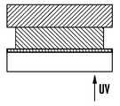
성장중인 물체의 상부 표면에 새로운 층이 형성되는 경우, 각각의 조사 단계 후, 구성 중에 있는 물체는 수지 "풀" 안으로 하강되고, 수지의 새로운 층이 상부에 코팅되며, 새로운 조사 단계가 행해진다. 이러한 기법의 초기 예가 도 3에서 Hull의 미국특허번호 5,236, 637에 주어져 있다. 이러한 "탑 다운(top down)" 기법의 단점은, 성장중인 물체를 (잠재적으로는 깊은) 액체 수지의 풀(pool)에 침지시키고 정밀한 액체 수지의 덧층(overlayer)을 재구성할 필요가 있다는 것이다.If a new layer is formed on the upper surface of the growing object, after each irradiation step, the object under construction is lowered into the resin "pool ", a new layer of resin is coated on top, and a new irradiation step is performed. An early example of such a technique is given in U.S. Patent No. 5,236,637 to Hull in FIG. A disadvantage of this "top down" technique is that it is necessary to immerse the growing object in a (potentially deep) pool of liquid resin and reconstruct an overlayer of precise liquid resin.
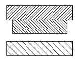
성장중인 물체의 저부에 새로운 층이 형성되는 경우에는, 각각의 조사 단계 후에, 구성 중에 있는 물체는 제작 웰(well)의 저부 플레이트로부터 분리되어야 한다. 이러한 기법의 초기 예가 도 4에서 Hull 의 미국특허번호 5,236,637에 주어져 있다. 이러한 "보톰 업(bottom up)" 기법은 대신 비교적 좁은 웰 또는 풀 밖으로 물체를 상승시킴으로써 물체가 침지되어 있는 깊은 웰에 대한 필요성을 제거하는 가능성을 유지하지만, 상업적으로 실행되는 바와 같은 이러한 "보톰 업" 제작 기법에 있어서의 문제는, 극도의 주의가 필요하며, 응고된 층을 저부 플레이트로부터 분리할 때 그들 사이의 물리적 및 화학적 상호작용으로 인해 추가적인 기계적 요소가 채용되어야 한다는 것이다. 예를 들어, 미국특허번호 7,438,846에는, 저부 구성 평면에서의 응고된 재료의 "비파괴적" 분리를 달성하기 위해 탄성 분리층이 사용된다. 미국 사우스다코타주 데드우드의 B9Creations에 의해 시판되는 B9Creator™ 3 차원 프린터와 같은 다른 접근법은 슬라이딩 빌드 플레이트를 채용한다. 예를 들어, M. Joyce, 미국특허출원 2013/0292862 및 Y. Chen 등, 미국특허출원 2013/0295212(양쪽 모두 2013년 11월 7일) 참조; 또한 Y. Pan 등,J. ManufacturingSci. andEng.134, 051011-1 (2012년 10월) 참조. 이러한 접근법은, 장치를 복잡하게 만들 수 있고, 방법을 느리게 할 수 있으며, 그리고/또는 최종 생산물을 잠재적으로 뒤틀리게 할 수 있는 기계적인 단계를 도입한다.If a new layer is formed at the bottom of the growing object, after each irradiation step, the object under construction must be separated from the bottom plate of the fabrication well. An early example of such a technique is given in U.S. Patent No. 5,236,637 to Hull in FIG. This "bottom up" technique instead maintains the possibility of eliminating the need for a deep well where the object is immersed by raising the object to a relatively narrow well or pool, but such "bottom up ""The problem with fabrication techniques is that extreme care is required and additional mechanical elements must be employed due to the physical and chemical interactions between them when separating the solidified layers from the bottom plate. For example, U. S. Patent No. 7,438, 846 uses an elastomeric separation layer to achieve "non-destructive" separation of the solidified material in the bottom construction plane. Another approach, such as the B9Creator ™ 3D printer, marketed by B9Creations of Deadwood, South Dakota, USA, employs a sliding build plate. See, for example, M. Joyce, U.S. Patent Application 2013/0292862 and Y. Chen et al., U.S. Patent Application 2013/0295212, both issued November 7, 2013; Y. Pan et al.,J. ManufacturingSci. andEng. 134, 051011-1 (October 2012). This approach introduces mechanical steps that can make the device complicated, slow the process, and / or potentially distort the final product.
3차원 물체를 생산하기 위한 연속 공정들이 미국특허번호 7,892,474에서 "탑 다운" 기법에 대해 일정 분량으로 제안되지만, 이러한 참고문헌은 상기 공정들이 생산되는 물품에 대해 비파괴적인 방식으로 "보톰 업" 시스템에서 어떻게 실행될 수 있는지를 설명하지 않는다. 따라서, "보텀 업" 제작에서 기계적인 분리 단계에 대한 필요성을 제거할 수 있는 3차원 제작을 위한 대안적 방법 및 장치에 대한 필요성이 있다.Although continuous processes for producing a three-dimensional object are proposed for a "top down" technique in U. S. Patent No. 7,892, 474, this reference teaches that the processes can be used in a "bottom up" system in a non-destructive manner It does not explain how it can be executed. There is therefore a need for alternative methods and apparatus for three-dimensional fabrication that can eliminate the need for a mechanical separation step in "bottom up" fabrication.
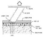
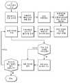
여기 기재된 것은 3차원 물체의 일반적으로 연속적인 생산을 위한 방법, 시스템 및 장치(관련된 제어 방법, 시스템 및 장치 포함)이다. 이 방법, 시스템 및 장치에서, 3차원 물체는 액체 계면으로부터 생성된다. 그러나, 상기 방법, 시스템 및 장치는 편의상 그리고 비제한적으로 "연속 액체 중간상(interphase) 인쇄"로서 칭해진다. 개략적인 모습이 본원의 도 1에 주어져 있다.Described herein are methods, systems, and apparatus (including associated control methods, systems, and apparatus) for generally continuous production of three-dimensional objects. In this method, system and apparatus, a three-dimensional object is created from a liquid interface. However, the methods, systems and devices are referred to as "continuous liquid interphase printing" for convenience and not limitation. A schematic view is given in Fig. 1 of the present application.
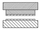
아래 논의된 바와 같이, 계면은 중합성 액체의 제1 및 제2 층 또는 구역들 사이에 있다. 제1 층 또는 구역(때로는 "데드 존"이라고도 칭함)은 (적어도 중합 억제 량의) 중합 억제제를 함유하고; 제2 층 또는 구역에서 억제제는 중합이 더 이상 실질적으로 억제되지 않는 지점까지 소비되었다(또는 다르게는 내부에 침투 또는 통합되어 있지 않다). 제1 및 제2 구역은 서로의 사이에 엄격한 계면을 형성하지 않고, 상기 층들 사이에는 뚜렷한 계면과 대조되는 중간상을 형성하는 것으로서 기술될 수도 있는 조성물의 구배가 있는데, 이는 상기 상들이 서로와 혼화될 수 있고 추가로 그 사이에 (그리고, 또한 제작되는 3차원 물체와 빌드 표면 - 빌드 표면을 통해 중합성 액체가 조사됨 - 사이에) (부분적으로 또는 완전히 중첩하는) 중합의 구배를 형성하기 때문이다. 3차원 물체는 (레이어바이레이어로 제작되지 않고) 중합의 구배로부터 연속적으로 제작, 성장, 또는 생성될 수 있다. 결과적으로, Y. Pan 등 또는 J. Joyce 등(위에 기재된)에 기재된 바와 같은 레이어바이레이어 기법에서 발생할 수 있는 생성되는 물체에 있어서의 결함 또는 분할선의 생성이 감소 또는 제거될 수 있다. 물론, 이러한 결함 또는 분할선은 아래에서 추가로 논의되는 바와 같이 원하는 경우 의도적으로 도입될 수 있다.As discussed below, the interface is between the first and second layers or zones of the polymerizable liquid. The first layer or zone (sometimes referred to as a "dead zone") contains a polymerization inhibitor (at least a polymerization inhibiting amount); In the second layer or zone the inhibitor has been consumed (or otherwise not penetrated or incorporated internally) to the point where polymerization is no longer substantially inhibited. The first and second zones do not form a strict interface between each other and there is a gradient of the composition that may be described as forming an intermediate phase contrasted with a distinct interface between the layers, (And partially overlapping or completely overlapping) between them (and also between the three-dimensional object being fabricated and the build surface - the polymeric liquid is irradiated through the build surface) . A three-dimensional object can be made, grown, or created continuously from a gradient of polymerization (rather than being made layer by layer). As a result, the generation of defects or splitting lines in a generated object that may occur in the layer-by-layer technique as described in Y. Pan et al. Or J. Joyce et al. (Described above) can be reduced or eliminated. Of course, such defects or splitting lines may be introduced intentionally as desired, as discussed further below.
연속 액체 중간상 인쇄의 일부 실시형태에서, 제1 층 또는 구역이 빌드 플레이트와 접촉하여 또는 빌드 플레이트의 상부에 인접하여 제공된다. 빌드 플레이트는 중합을 개시시키는 조사(예를 들어, 패턴화된 방사선)에 대해 투명하지만, 빌드 플레이트는 바람직하게는 중합 억제제에 대해 반투과성이며 (예를 들어, "데드 존"에 억제제를 연속적으로 공급하기 위해) 중합 억제제(예를 들어, 산소)가 부분적으로 또는 완전히 빌드 플레이트를 통과하는 것을 허용한다. 빌드 플레이트는 바람직하게는 (레이어바이레이어 공정에서와 같은) 별도의 또는 순차적인 단계를 생성하기 위해 슬라이드, 후퇴, 복귀 등을 할 필요가 없다는 의미에서 "고정" 또는 "정지"되어 있다. 물론, 중합의 구배를 과도하게 방해하지 않고 액체 계면으로부터의 연속적인 중합을 계속해서 허용하는 x 및/또는 y 방향의 빌드 플레이트의 작은 동작은 아래에서도 논의되는 바와 같이 일부 실시형태에서는 수용될 수 있다.In some embodiments of continuous liquid intermediate printing, the first layer or zone is provided in contact with or adjacent to the top of the build plate. The build plate is transparent to radiation initiating polymerization (e.g., patterned radiation), but the build plate is preferably semipermeable to the polymerization inhibitor (e.g., continuously supplying the inhibitor to the "dead zone" (E. G., Oxygen) to pass partially or fully through the build plate. ≪ / RTI > The build plate is preferably "fixed" or "stopped" in the sense that it does not need to slide, retract, return, etc. to create separate or sequential steps (such as in a layer by layer process). Of course, the small operation of the build plate in the x and / or y direction, which continues to allow continuous polymerization from the liquid interface without unduly interfering with the gradient of polymerization, can be accommodated in some embodiments, as will also be discussed below .
따라서, 본 발명은 3차원 물체를 형성하는 방법을 제공하며, 상기 방법은, 빌드 표면을 갖는 광학적으로 투명한 부재 및 캐리어를 제공하는 단계로서, 상기 캐리어 및 상기 빌드 표면은 그 사이에 빌드 영역을 형성하는 단계; 상기 빌드 영역에 중합성 액체를 충전하는 단계; 상기 중합성 액체로부터 고체 중합체를 형성하기 위해 상기 광학적으로 투명한 부재를 통해 상기 빌드 영역을 조사하는 동시에 상기 고체 중합체로부터 상기 3차원 물체를 형성하기 위해 상기 빌드 표면으로부터 멀어지게 상기 캐리어를 전진시키고, 또한 동시에(i) 중합성 액체의 데드 존을 상기 빌드 표면과 접촉하는 상태로 연속적으로 유지시키고,(ii) 상기 데드 존과 상기 고체 중합체와의 사이에서 그리고 그 각각과 접촉하는 상태로 중합 구역의 구배를 연속적으로 유지시키는 단계로서, 상기 중합 구역의 구배는 부분적으로 경화된 형태의 상기 중합성 액체를 포함하는(예를 들어, 그에 따라 상기 3차원 물체의 고체 중합체의 층 사이에서 결함 또는 분할선의 형성이 감소된다) 단계를 포함한다. 일부 실시형태에서, 광학적으로 투명한 부재는 반투과성 부재를 포함하고, 상기 데드 존을 연속적으로 유지시키는 단계는 상기 광학적으로 투명한 부재를 통해 중합 억제제를 공급하여 상기 데드 존에서, 그리고 선택적으로는 적어도 상기 중합 구역의 구배의 일부에서 억제제의 구배를 생성함으로써 실행되고; 다른 실시형태에서, 광학적으로 투명한 부재는, 반투과성 부재를 포함하고, 공정 동안 억제제의 추가적인 공급 없이 제작되는 물품을 생산하기 위해 충분한 길이의 시간 동안 데드 존을 연속적으로 유지시키도록 충분한 양(또는 "풀")의 억제제를 포함하도록 구성된다. 일부 실시형태에서, 광학적으로 투명한 부재는 반투과성 플루오로중합체, 강성 가스 투과성 중합체, 다공성 유리, 또는 이들의 조합물을 포함한다. 일부 실시형태에서, 조사 단계는 상기 빌드 영역 안으로 투사되는 2차원 방사선 패턴에 의해 실행되고, 상기 패턴은 시간에 따라 변하는 한편, 상기 동시에 전진시키는 단계는 상기 3차원 물체를 형성하는데 충분한 시간 동안(즉, 그 시간 동안 상기 중합 구역의 구배가 유지됨) 연속된다.Accordingly, the present invention provides a method of forming a three-dimensional object, the method comprising: providing an optically transparent member and a carrier having a build surface, wherein the carrier and the build surface form a build area therebetween ; Filling the build region with a polymerizable liquid; Exposing said build area through said optically transparent member to form a solid polymer from said polymeric liquid and advancing said carrier away from said build surface to form said three dimensional object from said solid polymer, At the same time,(i) continuously maintaining the dead zone of the polymerizable liquid in contact with the build surface, and(ii) bringing the gradient of the polymerization zone into contact with and between the dead zone and the solid polymer Wherein the gradient of the polymerization zone is selected from the group consisting of a partially cured form of the polymeric liquid (e.g., forming a defect or splitting line between the layers of the solid polymer of the three- Is reduced). In some embodiments, the optically transparent member comprises a semipermeable member, and the step of continuously maintaining the dead zone comprises supplying the polymerization inhibitor through the optically transparent member to cause the polymerization reaction to occur in the dead zone and, By creating a gradient of inhibitor in a portion of the gradient of the zone; In another embodiment, the optically transparent member comprises a semipermeable member and is provided with a sufficient amount (or "pull ") to maintain the dead zone continuously for a length of time sufficient to produce the article, "). ≪ / RTI > In some embodiments, the optically transparent member comprises a semipermeable fluoropolymer, a rigid gas permeable polymer, a porous glass, or a combination thereof. In some embodiments, the irradiating step is performed by a two-dimensional radiation pattern projected into the build area, the pattern varying with time, while the step of advancing simultaneously is performed for a time sufficient to form the three- , During which the gradient of the polymerization zone is maintained).
데드 존 및 중합 구역의 구배는 (2개가 만나는 위치에서) 그 사이에 뚜렷한 경계를 갖지 않지만, 중합 구역의 구배의 두께는 일부 실시형태에서 적어도 데드 존의 두께만큼 크다. 따라서, 일부 실시형태에서, 데드 존은 0.01, 0.1, 1, 2, 또는 10미크론 내지 100, 200, 또는 400미크론 이상의 두께를 가지며, 그리고/또는 상기 중합 구역의 구배 및 상기 데드 존은 함께 1 또는 2미크론 내지 400, 600, 또는 1000미크론 이상의 두께를 갖는다. 일부 실시형태에서, 중합 구역의 구배는 적어도 5, 10, 15, 20 또는 30초 내지 5, 10, 15 또는 20분 이상의 시간 동안 또한 3차원 생산물의 완성 때까지 중합 단계가 연속되는 상태에서 유지된다.The gradient of the dead zone and the polymerization zone does not have a clear boundary therebetween (where the two meet), but the thickness of the gradient of the polymerization zone is at least as great as the thickness of the dead zone in some embodiments. Thus, in some embodiments, the dead zone has a thickness of at least 0.01, 0.1, 1, 2, or 10 microns to 100, 200, or 400 microns, and / or the gradient of the polymerization zone and the dead zone 2 microns to 400, 600, or 1000 microns thick. In some embodiments, the gradient of the polymerization zone is maintained for at least 5, 10, 15, 20, or 30 seconds to 5, 10, 15, or 20 minutes or more, .
상기 방법은, (예를 들어, 의도적인 분할을 위한 미리 정해진 원하는 위치, 또는 분할의 방지 또는 분할의 감소가 중요하지 않은 상기 물체의 위치에서) 상기 3차원 물체에 분할선을 형성하는데 충분한 시간 동안 상기 중합 구역의 구배를 중단시키는 단계, 및 그 후 (예를 들어, 전진 단계의 정지 및 재개, 조사 강도의 증가, 그 후 감소, 및 이들의 조합에 의해) 상기 중합 구역의 구배를 복귀시키는 단계를 더 포함할 수 있다.The method may further comprise, for a time sufficient to form a dividing line in the three-dimensional object (e.g., at a predetermined desired location for intentional partitioning, or at a location of the object where prevention of partitioning or reduction of partition is not critical) Stopping the gradient of the polymerization zone, and then returning the gradient of the polymerization zone (e.g., by stopping and restarting the advancing step, increasing the irradiance intensity, then reducing, and combinations thereof) As shown in FIG.
상기 방법은, (예를 들어, 아래 예에서 주어진 바와 같은 양으로) 빌드 영역에서의 중합 액체의 점도를 감소시키기 위해 (예를 들어, 아래 예에서 주어진 바와 같은 양으로) 상기 중합성 액체가 빌드 영역에 공급될 때 그리고/또는 빌드 영역 내에서 중합성 액체를 가열하는 단계를 더 포함할 수 있다.The method may be used to reduce the viscosity of the polymerized liquid in the build area (e.g., in the amount given in the example below) (for example, in the same amount as given in the example below) Heating the polymerizable liquid when supplied to the area and / or within the build area.
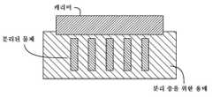
상기 캐리어가 내부에 형성된 적어도 하나의 채널을 갖고, 상기 충전 단계는 상기 적어도 하나의 채널을 통해 상기 중합성 액체를 상기 빌드 영역 안으로 통과시키거나 가압하는 방식으로 상기 방법이 수행되고 그리고 장치가 구현될 수 있다(예를 들어, 상기 캐리어는 내부에 형성된 복수의 채널을 갖고, 상이한 중합성 액체가 상기 복수의 채널의 상이한 채널들을 통해 가압되고; 예를 들어, 상기 물체로부터 분리된 적어도 하나 또는 복수의 외부 공급 도관을 동시에 형성하는 단계를 더 포함하고, 상기 적어도 하나의 공급 도관의 각각은 적어도 하나의 또는 복수의 상이한 중합성 액체를 상기 캐리어로부터 상기 빌드 구역으로 공급하기 위해 상기 캐리어의 채널과 유체 소통한다). 일부 실시형태에서, 반투과성 부재는 0.1 또는 1밀리미터 내지 10 또는 100밀리미터의 두께를 갖고, 그리고/또는 상기 반투과성 부재는 적어도 10Barrer의 산소 투과성을 갖는다.Wherein the carrier has at least one channel formed therein and wherein the filling step is carried out in such a manner that the polymeric liquid is passed or pressurized through the at least one channel into the build area, (E. G., The carrier has a plurality of channels formed therein, wherein different polymerizable liquids are pressurized through different channels of the plurality of channels; for example, at least one or more Wherein each of the at least one supply conduit is in fluid communication with a channel of the carrier to supply at least one or a plurality of different polymerizable liquids from the carrier to the build zone, do). In some embodiments, the semipermeable member has a thickness of 0.1 or 1 millimeter to 10 or 100 millimeters, and / or the semipermeable member has an oxygen permeability of at least 10 Barrer.
본 발명의 일 특정 양태는 따라서 3차원 물체를 형성하는 방법이며, 상기 방법은, 캐리어, 및 빌드 표면을 갖는 광학적으로 투명한 부재를 제공하는 단계로서, 캐리어 및 빌드 표면은 그 사이에 빌드 영역을 형성하는, 단계; 빌드 영역에 중합성 액체를 충전하는 단계; 중합성 액체로부터 고체 중합체를 형성하기 위해 광학적으로 투명한 부재를 통해 빌드 영역을 조사하는 단계와 동시에 고체 중합체로부터 3차원 물체를 형성하기 위해 빌드 표면으로부터 멀어지게 캐리어를 전진시키는 단계와, 또한 동시에, (ⅰ) 중합성 액체의 데드 존을 빌드 표면에 접촉시키는 상태로 연속적으로 유지시키는 단계, 및 (ⅱ) 데드 존과 고체 중합체와의 사이의 중합 구역의 구배 및 그 각각과의 접촉 상태를 연속적으로 유지시키는 단계로서, 중합 구역의 구배는 부분적으로 경화된 형태의 중합성 액체를 포함하는, 단계를 포함한다.One particular aspect of the present invention is thus a method of forming a three-dimensional object, the method comprising: providing an optically transparent member having a carrier and a build surface, wherein the carrier and build surface form a build area therebetween Step; Filling the build region with a polymerizable liquid; Advancing the carrier away from the build surface to form a three-dimensional object from the solid polymer simultaneously with the step of irradiating the build region through an optically transparent member to form a solid polymer from the polymerizable liquid, (I) continuously maintaining the dead zone of the polymerizable liquid in contact with the build surface, and (ii) continuously maintaining the gradient of the polymerization zone between the dead zone and the solid polymer and their respective contact zones Wherein the gradient of the polymerization zone comprises a partially cured form of the polymerizable liquid.
일부 실시형태에서, 광학적으로 투명한 부재는 반투과성 부재를 포함하고, 데드 존을 연속적으로 유지시키는 단계는, 광학적으로 투명한 부재를 통해 중합 억제제를 공급하여 데드 존 및 선택적으로는 중합 구역의 구배의 적어도 일부에서 억제제의 구배를 형성함으로써 실행된다.In some embodiments, the optically transparent member comprises a semipermeable member, and the step of continuously maintaining the dead zone comprises supplying the polymerization inhibitor through an optically transparent member to form a dead zone and optionally at least a portion of the gradient of the polymerization zone Lt; RTI ID = 0.0 > inhibitor < / RTI >
전술한 일부 실시형태에서, 광학적으로 투명한 부재는 반투과성 플루오로중합체, 강성 가스 투과성 중합체, 다공성 유리, 또는 이들의 조합을 포함한다.In some of the above-described embodiments, the optically transparent member comprises a semipermeable fluoropolymer, a rigid gas permeable polymer, a porous glass, or a combination thereof.
전술한 일부 실시형태에서, 조사 단계는 마스크리스 포토리소그래피에 의해 실행된다.In some of the embodiments described above, the irradiating step is performed by maskless photolithography.
전술한 일부 실시형태에서, 조사 단계는 빌드 영역 안으로 투사되는 2차원 방사선 패턴에 의해 실행되며, 동시에 전진시키는 단계가 3차원 물체를 형성하는데 충분한 시간 동안 연속되는 동안 패턴은 시간에 걸쳐 변화된다.In some of the embodiments described above, the irradiating step is carried out by a two-dimensional radiation pattern projected into the build area, while the pattern is changed over time, while the step of advancing simultaneously continues for a sufficient time to form a three-dimensional object.
전술한 일부 실시형태에서, 중합 구역의 구배 및 데드 존은 함께 1 내지 1000 미크론의 두께를 갖는다.In some of the embodiments described above, the gradient of the polymerization zone and the dead zone together have a thickness of 1 to 1000 microns.
전술한 일부 실시형태에서, 중합 구역의 구배는 적어도 5초의 시간 동안 유지된다.In some of the embodiments described above, the gradient of the polymerization zone is maintained for a time of at least 5 seconds.
전술한 일부 실시형태에서, 상기 방법은 3차원 물체에 분할선을 형성하는데 충분한 시간 동안 중합 구역의 구배를 중단시키는 단계를 더 포함한다.In some of the embodiments described above, the method further comprises stopping the gradient of the polymerization zone for a time sufficient to form a dividing line in the three-dimensional object.
전술한 일부 실시형태에서, 상기 방법은 빌드 영역의 상기 중합성 액체의 점도를 감소시키기 위해 중합성 액체를 가열하는 단계를 더 포함한다.In some of the embodiments described above, the method further comprises heating the polymerizable liquid to reduce the viscosity of the polymerizable liquid in the build area.
전술한 일부 실시형태에서, 캐리어는 내부에 형성된 적어도 하나의 채널을 갖고, 충전 단계는 적어도 하나의 채널을 통해 빌드 영역 안으로 중합성 액체를 지나가게 하거나 가압함으로써 실행된다.In some of the embodiments described above, the carrier has at least one channel formed therein, and the filling step is performed by passing or pushing the polymerizable liquid through the at least one channel into the build area.
전술한 일부 실시형태에서, 반투과성 부재는 0.1 내지 100 밀리미터의 두께를 갖고, 그리고/또는 반투과성 부재는 적어도 7.5×10⁻¹⁷m2s-1Pa-1(10 Barrer)의 산소 투과성을 가지며, 그리고/또는 반투과성 부재는 반투과성 플루오로중합체, 강성 가스-투과성 중합체, 다공성 유리, 또는 이들의 조합으로 형성된다.In the foregoing some embodiments, the semi-transparent member has a thickness of 0.1 to 100 millimeters, and / or semi-transparent member has an oxygen permeability of at least7.5 × 10 -17 m 2 s -1 Pa -1 (10 Barrer), and / Or the semipermeable member is formed of a semipermeable fluoropolymer, a rigid gas-permeable polymer, a porous glass, or a combination thereof.
전술한 일부 실시형태에서, 조사 단계는 화학 방사선에 의해 실행된다.In some of the embodiments described above, the irradiating step is carried out by actinic radiation.
전술한 일부 실시형태에서, 동시에 전진시키는 단계는 1초당 적어도 0.1, 1, 10, 100 또는 1000 미크론의 누적률에서 실행된다.In some of the embodiments described above, simultaneous advancing is performed at a cumulative rate of at least 0.1, 1, 10, 100 or 1000 microns per second.
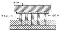
전술한 일부 실시형태에서, 캐리어는 그 위에 가용성 희생층을 갖고, 3차원 물체는 가용성 희생층 위에 형성된다.In some of the embodiments described above, the carrier has a soluble sacrificial layer thereon, and the three-dimensional object is formed over the soluble sacrificial layer.
전술한 일부 실시형태에서, 빌드 영역의 총 표면적은 빌드 표면의 총 표면적의 적어도 70 퍼센트를 차지하며, 그리고/또는 임의의 방향의 캐리어 및 물체의 측방 이동은 대응하는 방향의 빌드 영역의 폭의 30 퍼센트보다 더 크지 않다.In some of the embodiments described above, the total surface area of the build area occupies at least 70 percent of the total surface area of the build surface, and / or lateral movement of the carrier and the object in any direction is equal to 30 times the width of the build area in the corresponding direction Not greater than a percent.
전술한 일부 실시형태에서, 중합성 액체는 자유 라디칼 중합성 액체를 포함하고, 억제제는 산소를 포함한다.In some of the embodiments described above, the polymerizable liquid comprises a free radical polymerizable liquid and the inhibitor comprises oxygen.
전술한 일부 실시형태에서, 중합성 액체는 산-촉매형 또는 양이온 중합성 액체를 포함하고, 억제제는 염기를 포함한다.In some of the embodiments described above, the polymerizable liquid comprises an acid-catalyzed or cationic polymerizable liquid and the inhibitor comprises a base.
전술한 일부 실시형태에서, 빌드 표면은 실질적으로 고정 또는 정지되어 있다.In some embodiments described above, the build surface is substantially stationary or stationary.
본 발명의 추가의 특정 양태는 중합성 액체로부터 3차원 물체를 형성하기 위한 장치이며, 상기 장치는, (a) 지지체, (b) 지지체와 작동적으로 연계된 캐리어로서, 캐리어 상에서 3차원 물체가 형성되는 캐리어, (c) 빌드 표면을 갖는 광학적으로 투명한 부재로서, 빌드 표면 및 캐리어는 그 사이에 빌드 영역을 형성하는, 광학적으로 투명한 부재, (d) 빌드 표면과 작동적으로 연계되며, 응고 중합을 위해 상기 빌드 영역 안으로 액체 중합체를 공급하도록 구성되는 액체 중합체 공급부, (e) 중합성 액체로부터 고체 중합체를 형성하기 위해 광학적으로 투명한 부재를 통해 빌드 영역을 조사하도록 구성되는 방사선원, (f) 고체 중합체로부터 3차원 물체를 형성하기 위해 빌드 표면으로부터 멀어지게 캐리어를 전진시키는 한편, 또한 동시에 (ⅰ) 중합성 액체의 데드 존을 빌드 표면에 접촉시키는 상태로 연속적으로 유지시키며, (ⅱ) 데드 존과 고체 중합체와의 사이의 중합 구역의 구배 및 그 각각과의 접촉 상태를 연속적으로 유지시키고, 중합 구역의 구배는 부분적으로 경화된 형태의 중합성 액체를 포함하도록 하기 위해, 캐리어 및 방사선원과 작동적으로 연계되는 제어기를 포함한다.A further specific embodiment of the present invention is an apparatus for forming a three-dimensional object from a polymerizable liquid, comprising: (a) a support; (b) a carrier operatively associated with the support, (C) an optically transparent member having a build surface, wherein the build surface and carrier are optically transparent members defining a build area therebetween, (d) operatively associated with the build surface, (E) a source of radiation configured to irradiate the build area through an optically transparent member to form a solid polymer from the polymeric liquid, (f) a solid polymer While simultaneously advancing the carrier away from the build surface to form a three-dimensional object from (i) the polymeric liquid Continuously maintaining the zone in contact with the build surface, (ii) continuously maintaining the gradient of the polymerization zone between the dead zone and the solid polymer and their contact with each other, and the gradient of the polymerization zone being partially And includes a carrier and a controller operatively associated with the source of radiation to include a polymeric liquid in a cured form.
전술한 일부 실시형태에서, 캐리어는, 내부에 형성된 적어도 하나의 채널을 갖고, 적어도 하나의 채널을 통해 빌드 영역 안으로 중합성 액체를 공급하도록 구성된다.In some of the embodiments described above, the carrier has at least one channel formed therein and is configured to supply the polymerizable liquid into the build area through at least one channel.
전술한 일부 실시형태에서, 캐리어는, 내부에 형성된 복수의 채널을 갖고, 복수의 채널의 상이한 채널을 통해 상이한 중합성 액체를 공급하도록 구성된다.In some of the embodiments described above, the carrier has a plurality of channels formed therein and is configured to supply a different polymeric liquid through different channels of the plurality of channels.
전술한 일부 실시형태에서, (예를 들어, 물체의 제작 과정에서 또는 물체와 동시에 제작되는) 물체로부터 분리된 적어도 하나 또는 복수의 외부 공급 도관을 더 포함하고, 적어도 하나의 공급 도관의 각각은 캐리어의 채널과 유체 소통하고 적어도 하나 또는 복수의 상이한 중합성 액체를 캐리어로부터 빌드 구역으로 공급하도록 구성된다.In some of the embodiments described above, the apparatus further comprises at least one or more external supply conduits separated from the object (e.g., fabricated in the process of manufacturing the object or simultaneously with the object), wherein each of the at least one supply conduit includes a carrier And to supply at least one or a plurality of different polymerizable liquids from the carrier to the build zone.
일부 실시형태에서, 빌드 플레이트는 실질적으로 고정 또는 정지되어 있다.In some embodiments, the build plate is substantially stationary or stationary.
일부 실시형태에서, 중합 억제제의 공급원은 반투과성 부재 내의 중합 억제제의 조장소이다.In some embodiments, the source of the polymerization inhibitor is the promoter of the polymerization inhibitor in the semipermeable member.
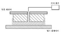
일부 실시형태에서, 반투과성 부재는 빌드 표면으로부터 분리된 공급 표면을 더 포함한다.In some embodiments, the semipermeable member further comprises a supply surface separate from the build surface.
일부 실시형태에서, 공급 표면은 중합 억제제의 공급원을 제공하기 위해 중합 억제제와 유체 접촉한다.In some embodiments, the feed surface is in fluid contact with the polymerization inhibitor to provide a source of polymerization inhibitor.
일부 실시형태에서, 상기 장치는 빌드 플레이트 및/또는 액체 중합체 공급부와 작동적으로 연계되는 가열기를 더 포함하고, 가열기는 빌드 영역에 있거나 빌드 영역에 공급되는 중합성 액체를 가열하도록 구성된다.In some embodiments, the apparatus further comprises a heater operatively associated with the build plate and / or the liquid polymer supply, wherein the heater is configured to heat the polymerizable liquid in the build zone or in the build zone.
일부 실시형태에서, 상기 장치는 빌드 플레이트와 작동적으로 연계되고 빌드 영역의 중합성 액체를 냉각하도록 구성되는 냉각기를 더 포함한다.In some embodiments, the apparatus further comprises a cooler operatively associated with the build plate and configured to cool the polymerizable liquid in the build region.
일부 실시형태에서, 반투과성 부재는 상부 표면 부분, 저부 표면 부분, 및 에지 표면 부분을 포함하고, 빌드 표면은 상부 표면 부분에 있으며, 공급 표면은 상부 표면 부분, 저부 표면 부분, 및 에지 표면 부분 중 적어도 하나에 있다.In some embodiments, the semipermeable member comprises an upper surface portion, a lower surface portion, and an edge surface portion, the build surface is at an upper surface portion, and the feed surface comprises at least an upper surface portion, a lower surface portion, It is in one.
일부 실시형태에서, 상기 장치는 액체 중합체 공급부와 작동적으로 연계되는 압력 공급원을 더 포함한다.In some embodiments, the apparatus further comprises a pressure source operatively associated with the liquid polymer supply.
일부 실시형태에서, 방사선원은 광원을 포함한다.In some embodiments, the radiation source comprises a light source.
일부 실시형태에서, 상기 장치는, 방사선원 및 제어기와 작동적으로 연계되며 마스크리스 포토리소그래피에 의해 중합성 액체의 조사를 실행하도록 구성되는 공간 광 조절 어레이를 포함한다.In some embodiments, the apparatus includes a spatial light modulator array operatively associated with the radiation source and the controller and configured to effect irradiation of the polymerizable liquid by maskless photolithography.
일부 실시형태에서, 캐리어는 적어도 하나의 액추에이터와 작동적으로 연계되는 플레이트, 기둥, 웨브, 막, 릴, 또는 이들의 조합을 포함한다.In some embodiments, the carrier comprises a plate, column, web, membrane, reel, or a combination thereof operatively associated with at least one actuator.
일부 실시형태에서, 캐리어는 구동장치를 포함하고, 구동장치 및 제어기는 캐리어를 빌드 표면으로부터 멀어지게 단일방향으로 전진시키도록 구성된다.In some embodiments, the carrier includes a driver, and the driver and controller are configured to advance the carrier in a single direction away from the build surface.
일부 실시형태에서, 캐리어는 그 위에 가용성 희생층을 갖고, 3차원 물체는 가용성 희생층 위에 형성된다.In some embodiments, the carrier has a soluble sacrificial layer thereon, and the three-dimensional object is formed over the soluble sacrificial layer.
B9Creator™ 3차원 인쇄기에서, 폴리디메틸실록산(PDMS) 코팅이 슬라이딩 빌드 표면에 도포된다. PDMS 코팅은 산소를 흡수하고 중합 억제제로서의 그 작용을 통해 미중합 수지의 얇은 윤활 막을 형성한다. 그러나, PDMS 코팅된 빌드 표면은 성장중인 물체 아래로부터 표면을 기계적으로 이동(슬라이딩)시키면서 와이퍼 블레이드에 의해 그로부터 미중합 수지를 와이핑하고, 그 후 성장중인 물체 아래의 그 이전 위치로 표면을 복귀시킴으로써 산소를 직접적으로 보충 받는다. 일부 실시형태에서, 산소와 같은 억제제를 제공하는 보조 수단(예를 들어, 연계된 채널에 대한 압축기)이 제공되지만, 공정은 여전히 표면의 슬라이딩 및 와이핑을 이용하는 레이어바이레이어 접근법을 채용한다. PDMS 코팅은 수지에 의해 팽창할 수 있기 때문에, 이러한 팽창은 기계적인 단계와 함께 PDMS 코팅의 파열 또는 PDMS 코팅에 대한 손상을 초래할 수 있다.In a B9Creator ™ three-dimensional press, a polydimethylsiloxane (PDMS) coating is applied to the sliding build surface. The PDMS coating absorbs oxygen and forms a thin lubricant film of the unpolymerized resin through its action as a polymerization inhibitor. However, the PDMS coated build surface can be used by mechanically moving (sliding) the surface from under the growing object, wiping the unpolymerized resin therefrom by the wiper blade, and then returning the surface to its previous position below the object under growing Oxygen is supplemented directly. In some embodiments, auxiliary means (e.g., compressors for associated channels) are provided that provide an inhibitor such as oxygen, but the process still employs a layer-by-layer approach that utilizes surface sliding and wiping. Since the PDMS coating can be expanded by the resin, this expansion can result in rupture of the PDMS coating or damage to the PDMS coating with the mechanical step.
본 발명의 비제한적인 예 및 특정 실시형태를 본원의 도면 및 이하의 명세서에서 보다 상세하게 설명한다. 모든 미국특허 참고 문헌의 개시내용은 그 전체가 참조로 본원에 통합된다.Non-limiting examples and specific embodiments of the present invention are described in more detail in the drawings and the following specification. The disclosures of all U. S. patent references are hereby incorporated by reference in their entirety.
도 1은 본 발명의 방법의 일 실시형태의 개략도이다.
도 2는 본 발명의 장치의 일 실시형태의 사시도이다.
도 3은 본 발명에서 사용하기 위한 강성 빌드 플레이트의 대안적 실시형태의 측단면도를 제공한다.
도 4는 본 발명에서 사용하기 위한 다양한 대안적 캐리어를 도시한다.
도 5는 빌드 플레이트의 빌드 표면에 미중합 막을 형성하는 것을 돕는 강성 빌드 플레이트의 중합 억제제를 도시한다.
도 6은 빌드 표면에 비중합 막을 형성하는 것을 돕기 위해 플레이트의 후방의 공급 표면으로부터 플레이트의 전방의 빌드 표면까지 빌드 플레이트를 통해 억제제(이 경우에는 산소)를 이동시키는 것을 도시한다.
도 7은, 후속 중합이 실행될 수 있기 전에 그들 사이의 간극이 충전되어야 하는, 빌드 표면으로부터 멀어지게 전진되어 있는 성장중인 3차원 물체를 도시한다.
도 8은 도 8에 도시된 간극의 충전을 촉진하기 위해 압력의 적용을 제공하는 본 발명의 실시형태를 개략적으로 도시한다.
도 9는 본 발명의 방법 및 장치에 의해 생산될 수 있는 로드 또는 섬유를 도시한다.
도 10은 본 발명의 방법 및 장치에 의해 제작되는 미소바늘 어레이의 사진이다. 어레이가 유지되는 캐리어의 직경은 재략 미국 25 센트 동전(또는 "4분의 1")과 동일하다. 본질적으로 동일한 캐리어가 아래 도시된 추가적인 예에서 사용된다.
도 11은 본 발명의 방법 및 장치에 의해 제작되는 제2 미소바늘 어레이의 사진이다.
도 12는 본 발명의 방법 및 장치에 의해 제작되는 링 구조물의 사진이다. 제작 동안의 광범위한 "돌출부(overhang)"를 유의하라.
도 13은 완성된 도 12의 링의 사진이다.
도 14는 본 발명의 방법 및 장치에 의해 제작되는 4개의 체스 부품 구조물의 사진이다.
도 15는 본 발명의 방법 및 장치에 의해 제작되는 직사각형 프리즘 구조물의 사진이다.
도 16은 본 발명의 방법 및 장치에 의해 제작되는 코일 구조물의 사진이다. 제작에서 완성된 구조물까지의 기간의 광범위한 "돌출부"를 유의하라
도 17은 경화 시간에 대한 염료 및 광개시제의 영향을 도시한다.
도 18은 상기 도 14에 도시된 것과 유사하지만 본 발명의 방법에 의해 염색 수지에 의해 형성된 체스 부품의 사진이다.
도 19는 분리 층을 갖는 캐리어에서의 복수의 물품의 제작을 개략적으로 도시한다.
도 20은 분리 층을 갖는 캐리어로부터의 복수의 물품의 분리를 개략적으로 도시한다.
도 21은 본 발명의 방법 및 장치에 의해 제작되는, 분리 층 상의, 프리즘의 어레이의 사진이다.
도 22는 분리 후의 도 21에 도시된 프리즘의 사진이다.
도 23은 본 발명의 방법 및 장치에 의해 생산되는 원통형 케이지 구조물의 사진이다.
도 24는, 폴리에틸렌 글리콜 중합체를 포함하는 것을 제외하고, 도 21의 것과 유사하고, 본질적으로 동일한 방법에 의해 생산되는 어레이의 사진이다.
도 25는, 폴리에틸렌 글리콜 중합체를 포함하는 것을 제외하고, 도 23의 것과 유사하고 실질적으로 동일한 방법에 의해 생산되는 원통형 케이지 구조물의 사진이다. 상기 부품은 가요성이라는 것을 유의하라.
도 26은 하나 이상의 가열기가 중합성 액체의 점도를 감소시키기 위해 포함되는 본 발명의 장치의 실시형태를 개략적으로 도시한다.
도 27은 빌드 영역에 캐리어를 통해 공급되는 중합성 액체가 충전되는 본 발명의 장치의 실시형태를 개략적으로 도시한다.
도 28은 캐리어로부터 빌드 영역으로의 하나 또는 다수의 중합성 액체의 공급을 용이하게 하기 위해 외부 도관이 형성되어 있는 본 발명의 실시형태를 개략적으로 도시한다.
도 29 내지 도 31은 본 발명을 실행하기 위한 제어 시스템 및 방법을 도시하는 순서도이다.Figure 1 is a schematic diagram of one embodiment of the method of the present invention.
2 is a perspective view of one embodiment of the apparatus of the present invention.
Figure 3 provides a side cross-sectional view of an alternative embodiment of a rigid build plate for use in the present invention.
Figure 4 illustrates various alternative carriers for use in the present invention.
Figure 5 shows the polymerization inhibitor of a rigid build plate that aids in forming an unpolymerized film on the build surface of the build plate.
Figure 6 shows the movement of the inhibitor (in this case oxygen) through the build plate from the supply surface at the rear of the plate to the build surface in front of the plate to help form a non-polymeric film on the build surface.
Figure 7 shows a growing three-dimensional object that is being advanced away from the build surface, where the gap between them must be filled before subsequent polymerization can be carried out.
8 schematically illustrates an embodiment of the present invention which provides application of pressure to facilitate filling of the gap shown in Fig.
Figure 9 illustrates a rod or fiber that may be produced by the method and apparatus of the present invention.
10 is a photograph of a micro-needle array fabricated by the method and apparatus of the present invention. The diameter of the carrier in which the array is held is the same as the
11 is a photograph of a second micro-needle array fabricated by the method and apparatus of the present invention.
12 is a photograph of a ring structure produced by the method and apparatus of the present invention. Note the extensive "overhang" during fabrication.
Fig. 13 is a photograph of the completed ring of Fig.
Figure 14 is a photograph of four chess piece constructions made by the method and apparatus of the present invention.
15 is a photograph of a rectangular prism structure fabricated by the method and apparatus of the present invention.
16 is a photograph of a coil structure produced by the method and apparatus of the present invention. Note the extensive "overhang" of the period from fabrication to finished structure
Figure 17 shows the effect of dye and photoinitiator on cure time.
18 is a photograph of a chess part similar to that shown in Fig. 14, but formed by the dyeing resin by the method of the present invention.
Figure 19 schematically shows the fabrication of a plurality of articles in a carrier with a separation layer.
Figure 20 schematically illustrates the separation of a plurality of articles from a carrier having a separation layer.
21 is a photograph of an array of prisms on a separation layer, produced by the method and apparatus of the present invention.
Fig. 22 is a photograph of the prism shown in Fig. 21 after the separation.
23 is a photograph of a cylindrical cage structure produced by the method and apparatus of the present invention.
Figure 24 is a photograph of an array similar to that of Figure 21 except that it contains a polyethylene glycol polymer and produced by essentially the same method.
Figure 25 is a photograph of a cylindrical cage structure produced by a method similar and substantially identical to that of Figure 23 except that it comprises a polyethylene glycol polymer. Note that the part is flexible.
Figure 26 schematically illustrates an embodiment of the apparatus of the present invention in which one or more heaters are included to reduce the viscosity of the polymerizable liquid.
Figure 27 schematically illustrates an embodiment of the apparatus of the present invention in which the polymerizable liquid supplied through the carrier into the build area is filled.
Figure 28 schematically illustrates an embodiment of the present invention in which an outer conduit is formed to facilitate the supply of one or more polymeric liquids from the carrier to the build area.
29 to 31 are flow charts showing a control system and method for carrying out the present invention.
이제 본 발명의 실시형태가 도시되어 있는 첨부의 도면을 참고하여 본 발명을 이하에서 상세하게 설명한다. 그러나, 본 발명은 많은 상이한 형태로 실시될 수 있고 여기 설명된 실시형태로 제한되는 것으로 해석되어서는 안되며, 이 실시형태들은 본 개시물이 면밀하고 완전해지도록 하고 본 발명의 범위를 통상의 기술자에게 충분히 전달되도록 하기 위해 제공된다.The present invention will now be described in detail with reference to the accompanying drawings, in which embodiments of the present invention are shown. It should be understood, however, that the present invention may be embodied in many different forms and should not be construed as limited to the embodiments set forth herein; To be sufficiently transmitted.
동일한 도면부호는 전체에 걸쳐 동일한 요소를 나타낸다. 도면에서, 소정 라인, 층, 구성요소, 요소 또는 특징부의 두께는 명확화를 위해 과장될 수 있다. 파선이 사용되는 경우, 파선은 달리 명시되지 않는 한 선택적인 특징부 또는 동작을 나타낸다.The same reference numerals denote the same elements throughout. In the drawings, the thickness of a given line, layer, element, element or feature may be exaggerated for clarity. If a dashed line is used, the dashed line indicates an optional feature or action, unless otherwise specified.
여기서 사용되는 용어는 단지 특정 실시형태를 설명하기 위한 것이며 본 발명을 한정하려는 것이 아니다. 여기서 사용되는 바와 같이, 단수 형태는 문맥상 명확히 달리 나타내지 않는 한 복수 형태도 포함하는 것이다. 용어 "포함하다" 또는 "포함하는"은, 본 명세서에서 사용될 때, 설명된 특징, 정수, 단계, 동작, 요소, 구성요소 및/또는 이들의 그룹 또는 조합의 존재를 명시하지만, 하나 이상의 다른 특징, 정수, 단계, 동작, 요소, 구성요소 및/또는 이들의 그룹 또는 조합을 배제하지 않는다는 것이 또한 이해될 것이다.The terminology used herein is for the purpose of describing particular embodiments only and is not intended to be limiting of the invention. As used herein, the singular forms include plural forms unless the context clearly dictates otherwise. The word "comprise" or "comprising" when used in this specification specifies the presence of stated features, integers, steps, operations, elements, components and / or groups or combinations thereof, , Integers, steps, operations, elements, components, and / or groups or combinations thereof.
여기서 사용될 때, 용어 "및/또는"은 관련된 열거된 항목의 임의의 그리고 모든 가능한 조합 또는 하나 이상을 포함할 뿐만 아니라, 대안("또는")으로 해석될 때는 조합이 결여되어 있는 것을 포함한다.When used herein, the term "and / or" includes any and all possible combinations or more than one of the listed items, as well as the absence of a combination when interpreted as an alternative (or "
달리 규정되지 않는 한, 여기서 사용되는 모든 용어(기술적 및 과학적 용어 포함)는 본 발명이 속하는 기술분야의 통상의 기술자에 의해 일반적으로 이해되는 것과 동일한 의미를 갖는다. 일반적으로 사용되는 사전에 규정된 것과 같은 용어는 명세서 및 청구항의 문맥에서의 그 의미와 일치하는 의미를 갖는 것으로 해석되어야 하며 본원에서 표현적으로 그렇게 규정되지 않는 한 이상화된 또는 지나치게 형식적인 의미로 해석되어서는 안 된다는 것이 또한 이해될 것이다. 잘 알려진 기능 또는 구성은 간결성 및/또는 명확성을 위해 상세하게 기재되지 않을 수 있다.Unless otherwise defined, all terms (including technical and scientific terms) used herein have the same meaning as commonly understood by one of ordinary skill in the art to which this invention belongs. Terms such as those defined in commonly used dictionaries should be construed as meaning consistent with their meanings in the context of the specification and the claims, and unless expressly so defined herein, interpreted in an idealized or overly formal sense It should also be understood that it should not be. Well-known functions or configurations may not be described in detail for brevity and / or clarity.
요소가 다른 요소 "상에 있는", 다른 요소에 "부착"되는, 다른 요소에 "연결"되는, 다른 요소에 "결합"되는, 다른 요소에 "접촉"하는 등과 같이 언급될 때, 요소는 또한 존재할 수 있는 다른 요소 또는 중간 요소 상에 있고, 그 요소에 직접적으로 부착, 그 요소에 연결, 그 요소에 결합 및/또는 그 요소에 접촉할 수 있다는 것이 이해될 것이다. 반대로, 요소가 예를 들어 다른 요소 "상에 직접적으로 있는", 다른 요소에 "직접적으로 부착되는", 다른 요소에 "직접적으로 연결되는", 다른 요소에 "직접적으로 결합되는", 또는 다른 요소에 "직접적으로 접촉하는" 것으로서 언급될 때, 거기에는 중간 요소가 존재하지 않는다. 또한, 다른 특징부에 "인접하여" 배치되는 구조물 또는 특징부에 대한 언급은 인접하는 특징부에 겹치거나 다른 특징부 아래에 놓일 수 있는 부분을 가질 수 있다는 것이 통상의 기술자에게 또한 인식될 것이다.When an element is referred to as being "on" another element, "attached" to another element, "connected" to another element, "contacting" another element, or the like, It will be understood that it may be present on other elements or intermediate elements that may be present and attached directly to, connected to, coupled to, and / or in contact with the element. On the contrary, when an element is referred to as being "directly on another element", "directly attached" to another element, "directly connected" to another element, "directly coupled" There is no intermediate element when it is referred to as "directly contacting" It will also be recognized by those of ordinary skill in the art that references to structures or features that are "adjacent" to other features may have portions that overlap or may lie below other features.
"하에", "아래에", "하부", "위", "상부" 등과 같은 공간적으로 상대적인 용어는 도면에 도시된 바와 같은 다른 요소(들) 또는 특징부(들)에 대한 요소 또는 특징부의 관계를 설명하기 위해 설명의 용이성을 위해 본원에서 사용될 수 있다. 공간적으로 상대적인 용어는 도면에 나타낸 배향 이외에 사용 또는 동작에 있어서의 장치의 상이한 배향을 포함하는 것이라는 것이 이해될 것이다. 예를 들어, 도면의 장치가 역전될 때, 다른 요소 또는 특징부 "아래에" 또는 "밑에"와 같이 기재되는 요소는 다른 요소 또는 특징부의 "위에" 배향될 것이다. 따라서, 예시적인 용어 "아래에"는 위 및 아래의 배향의 양쪽 모두를 포함할 수 있다. 장치는 달리 배향될 수 있고(90 도 또는 다른 배향으로 회전), 여기서 사용되는 공간적으로 상대적인 기술어는 그에 따라 해석된다. 유사하게는, 용어 "상방으로", "하방으로", "수직인", "수평인" 등은 명확하게 달리 지시되지 않는 한 단지 설명을 위해 사용된다.Spatially relative terms, such as "under", "under", "under", "above", "top", etc., May be used herein for ease of explanation to illustrate the relationship. It will be appreciated that spatially relative terms are meant to encompass different orientations of the device in use or operation in addition to the orientation shown in the figures. For example, when an apparatus in the drawings is reversed, other elements or elements described as "under" or "under" a feature will be "on" another element or feature. Thus, the exemplary term "below" may include both the orientation above and below. Devices can be oriented differently (rotated in 90 degrees or other orientations), and the spatially relative descriptors used here are interpreted accordingly. Similarly, the terms "upward "," downward ", "vertical "," horizontal ", and the like are used merely for illustration unless explicitly indicated otherwise.
용어 제1, 제2 등이 다양한 요소, 구성요소, 영역, 층 및/또는 구간을 설명하기 위해 본원에서 사용되지만, 이들 요소, 구성요소, 영역, 층 및/또는 구간은 이러한 용어에 의해 제한되어서는 안된다는 것이 이해될 것이다. 그보다는, 이러한 용어는 단지 하나의 요소, 구성요소, 영역, 층 및/또는 구간을 다른 요소, 구성요소, 영역 및/또는 구간으로부터 구별하기 위해 사용된다. 따라서, 본원에서 논의되는 제1 요소, 구성요소, 영역, 층 또는 구간은 본 발명의 교시 내에서 제2 요소, 구성요소, 영역, 층 또는 구간을 말할 수 있다. 동작(또는 단계)의 시퀀스는 구체적으로 달리 지시되지 않는 한 청구항 또는 도면에 나타낸 순서로 제한되지 않는다.Although the terms first, second, etc. are used herein to describe various elements, components, regions, layers and / or sections, these elements, components, regions, layers and / It should be understood that no. Rather, such terms are used to distinguish one element, component, region, layer, and / or region from another, component, region, and / or region. Thus, the first element, component, region, layer or section discussed herein may refer to a second element, component, region, layer or section within the teachings of the present invention. The sequence of operations (or steps) is not specifically limited in the order shown in the claims or drawings unless otherwise indicated.
1.One.중합성Polymerizable 액체 Liquid
임의의 적절한 중합성 액체가 본 발명을 가능하게 하기 위해 사용될 수 있다. 액체(때로는 본원에서 "액체 수지", "잉크", 또는 간단히 "수지"를 칭하기도 함)는 단량체, 특히 광중합성 및/또는 자유 라디칼 중합성 단량체, 및 자유 라디칼 개시제와 같은 적절한 개시제, 및 이들의 조합을 포함할 수 있다. 예는 아크릴, 메타크릴산, 아크릴아미드, 스티레닉(styrenic), 올레핀, 할로겐화 올레핀, 시클릭 알켄, 말레산 무수물, 알켄, 알킨, 일산화탄소, 관능화 올리고머, 다관능성 큐트 부위 단량체(multifunctional cute site monomer), 관능화 PEG 등과 이들의 조합을 포함하지만, 이들로 제한되는 것은 아니다. 액체 수지, 단량체 및 개시제의 예는 미국특허번호 8,232,043; 8,119,214; 7,935,476; 7,767,728; 7,649,029; WO 2012129968 A1; CN 102715751 A; JP 2012210408 A에 설명된 것을 포함하지만 이들로 제한되지 않는다.Any suitable polymeric liquid may be used to enable the present invention. Liquid (sometimes referred to herein as "liquid resin "," ink ", or simply "resin") may also include suitable initiators such as monomers, especially photopolymerizable and / or free radical polymerizable monomers, As shown in FIG. Examples include but are not limited to acryl, methacrylic acid, acrylamide, styrenic, olefins, halogenated olefins, cyclic alkenes, maleic anhydrides, alkenes, alkynes, carbon monoxide, functionalized oligomers, multifunctional cute site monomers ), Functionalized PEG, and the like, and combinations thereof. Examples of liquid resins, monomers and initiators are described in U.S. Patent Nos. 8,232,043; 8,119,214; 7,935,476; 7,767,728; 7,649,029; WO 2012129968 A1; CN 102715751 A; But are not limited to, those described in JP 2012210408 A.
산 촉매형중합성액체.위에 기재된 바와 같은 일부 실시형태에서, 중합성 액체는 자유 라디칼 중합성 액체(이 경우에 억제제는 하이 기재된 바와 같이 산소일 수 있다)를 포함하지만, 다른 실시형태에서 중합성 액체는 산 촉매형 또는 양이온 중합형 중합성 액체를 포함한다. 이러한 실시형태에서, 중합성 액체는 에폭시드기, 비닐 에테르기 등과 같은 산 촉매작용에 적합한 단량체 함유기를 포함한다. 따라서, 적절한 단량체는 메톡시에텐, 4-메톡시스티렌, 스티렌, 2-메틸프로프-1-엔, 1,3-부타디엔 등과 같은 올레핀; 옥시란, 티에탄, 테트라히드로푸란, 옥사졸린, 1,3, 디옥세판, 옥세탄-2-온 등과 같은 헤테로시클로익 단량체(락톤, 락탐, 및 시클릭 아민을 포함), 및 이들의 조합을 포함한다. 적절한 (일반적으로 이온성 또는 비-이온성) 광산 발생제 (PAG)가 산 촉매형 중합성 액체에 포함되고, 상기 산 촉매형 중합성 액체의 예는, 오늄 염, 술포늄 및 아이오도늄 염 등, 예컨대 디페닐 아이오다이드 헥사플루오로포스페이트, 디페닐 아이오다이드 헥세플루오로아르세네이트, 디페닐 아이오다이드 헥사플루오로안티모네이트, 디페닐 p-메톡시페닐 트리플레이트, 디페닐 p-톨루에닐 트리플레이트, 디페닐 p-이소부틸페닐 트리플레이트, 디페닐 p-테르트-부틸페닐 트리플레이트, 트리페닐술포늄 헥사플루오로르포스페이트, 트리페닐술포늄 헥사플루오로아르세네이트, 트리페닐술포늄 헥사플루오로안티모네이트, 트리페닐술포늄 트리플레이트, 디부틸나프틸술포늄 트리플레이트 등과 이들의 혼합물을 포함하지만 이들로 제한되지는 않는다. 예를 들어, 미국특허번호 7,824,839; 7,550,246; 7,534,844; 6,692,891; 5,374,500; 및 5,017,461 참조; 또한Photoacid Generator Selection Guide for the electronics industry and energy curable coatings(BASF 2010) 참조.Acid catalyst typepolymerizableLiquid. In some embodiments, as described above, the polymerizable liquid comprises a free radical polymerizable liquid (in which case the inhibitor may be oxygen as described above), but in another embodiment the polymerizable liquid comprises an acid-catalyzed or cationic And a polymerizable type polymerizable liquid. In such embodiments, the polymerizable liquid comprises monomer containing groups suitable for acid catalysis, such as epoxides, vinyl ether groups, and the like. Thus, suitable monomers include olefins such as methoxyethene, 4-methoxystyrene, styrene, 2-methylprop-1-ene, 1,3-butadiene and the like; (Including lactones, lactams and cyclic amines) such as oxirane, thietane, tetrahydrofuran, oxazoline, 1,3, dioxepane, oxetan-2-one and the like, . Suitable (generally ionic or non-ionic) photoacid generators (PAG) are included in the acid-catalyzed polymeric liquids, examples of which are onium salts, sulfonium and iodonium salts , Diphenyl iodide hexafluoroarsenate, diphenyl iodide hexafluoroantimonate, diphenyl p-methoxyphenyl triflate, diphenyl p-methoxyphenyl triflate, diphenyl iodide hexafluorophosphate, diphenyl iodide hexafluoroarsenate, diphenyl iodide hexafluoroantimonate, -Toluenyl triflate, diphenyl p-isobutylphenyl triflate, diphenyl p-tert-butylphenyl triflate, triphenylsulfonium hexafluorophosphate, triphenylsulfonium hexafluoroarsenate, tri Phenylsulfonium hexafluoroantimonate, triphenylsulfonium triflate, dibutylnaphthylsulfonium triflate, and the like, and mixtures thereof, but are not limited thereto. See, for example, U.S. Patent Nos. 7,824,839; 7,550,246; 7,534,844; 6,692,891; 5,374,500; And 5,017,461; See alsoPhotoacidGenerator Selection Guide for the electronics industry and energy curable coatings (BASF 2010).
히드로겔.일부 실시형태에서, 적합한 수지는 폴리(에틸렌 글리콜)(PEG) 및 젤라틴 같은 광경화성 히드로겔을 포함한다. PEG 히드로겔은, 성장 인자를 포함하는 다양한 생물학적 제제를 전달하기 위해 사용되어 왔지만, 사슬 성장 중합에 의해 가교되는 PEG 히드로겔에 직면하는 큰 도전은 비가역 단백질 손상에 대한 가능성이다. 광중합되는 PEG 디아크릴레이트 히드로겔로부터의 생물학적 제제의 분리를 최대화시키기 위한 조건은, 광중합 전에 단량체 수지 용액에 친화력 결합 펩티드 서열을 포함시켜 연속적 전달을 허용함으로써 향상될 수 있다. 젤라틴은 음식, 화장품, 제약 및 사진 산업에서 주로 사용되는 생물중합체이다. 젤라틴은 콜라겐의 열변성 또는 화학적 및 물리적 열화에 의해 획득된다. 동물, 어류 및 인간에서 발견되는 것을 포함하여 3가지 종류의 젤라틴이 있다. 냉수성 어류의 피부로부터의 젤라틴은 제약 용례에 사용하기에 안전한 것으로 생각된다. UV 또는 가시광은 적절히 수정된 젤라틴을 가교하기 위해 사용될 수 있다. 젤라틴을 가교하기 위한 방법은 로즈벵갈(Rose Bengal)과 같은 염료로부터의 경화 유도체를 포함한다.Hydrogel. In some embodiments, suitable resins include photocurable hydrogels such as poly (ethylene glycol) (PEG) and gelatin. PEG hydrogels have been used to deliver a variety of biological agents including growth factors, but a major challenge facing PEG hydrogels crosslinked by chain growth polymerization is the potential for irreversible protein damage. The conditions for maximizing the separation of the biological agent from the photopolymerized PEG diacrylate hydrogel may be enhanced by including an affinity binding peptide sequence in the monomer resin solution prior to photopolymerization to allow continuous delivery. Gelatin is a biopolymer commonly used in the food, cosmetic, pharmaceutical and photographic industries. Gelatin is obtained by thermal denaturation or chemical and physical degradation of collagen. There are three types of gelatin, including those found in animals, fish and humans. Gelatin from the skin of cold water fish is considered safe for use in pharmaceutical applications. UV or visible light can be used to crosslink the suitably modified gelatin. Methods for crosslinking gelatin include curing derivatives from dyes such as Rose Bengal.
광경화성 실리콘수지.적합한 수지는 광경화성 실리콘을 포함한다. Siliopren™ UV Cure Silicone Rubber와 같은 UV 경화 실리콘 루버가 LOCTITE™ Cure Silicone 접착제 실란트로서 사용될 수 있다. 용례는 광학 계기, 의료 및 수술 장비, 외부 조명 및 인클로져(enclosure), 전기 커넥터/센서, 광섬유 및 개스킷을 포함한다.Photocurablesiliconeresin. Suitable resins include photocurable silicon. UV cured silicone louvers, such as Siliopren ™ UV Cure Silicone Rubber, can be used as LOCTITE ™ Cure Silicone adhesive sealants. Examples include optical instruments, medical and surgical instruments, external lights and enclosures, electrical connectors / sensors, optical fibers and gaskets.
생분해성수지.생분해성 수지는 약을 전달하기 위한 삽입가능 장치 또는 생분해성 나사 및 스텐트(미국특허 7,919,162; 6,932,930) 같은 일시적 동작 용례를 위해 특히 중요하다. 락트산 및 글리콜산(PLGA)의 생분해성 공중합체가 사용에 적합한 투명 수지를 산출하기 위해 PEG 디메타크릴레이트에 용해될 수 있다. 폴리크프로락톤 및 PLGA 올리고머는 이들이 사용에 효과적인 수지가 될 수 있도록 하기 위해 아크릴기 또는 메타크릴기에 의해 관능화될 수 있다.Biodegradableresin. Biodegradable resins are particularly important for transient operating applications such as implantable devices for delivering drugs or biodegradable screws and stents (U.S. Patent No. 7,919,162; 6,932,930). Biodegradable copolymers of lactic acid and glycolic acid (PLGA) can be dissolved in PEG dimethacrylate to yield transparent resins suitable for use. Polycroprolactone and PLGA oligomers can be functionalized with acrylic or methacrylic groups to enable them to be effective resins for use.
광경화성폴리우레탄.특히 유용한 수지는 광경화성 폴리우레탄이다. (1) 알리패틱 디이소시아네이트, 폴리(헥사메틸렌 이소프탈레이트 글리콜) 및 선택적으로는 1,4-부탄디올에 기초한 폴리우레탄; (2) 다관능 아크릴산 에스테르; (3) 광개시제; 및 (4) 산화방지제를 포함하는 광중합성 폴리우레탄 조성물은, 그것이 경질이고, 내마모성이며, 얼룩 방지성인 재료를 제공하도록 배합될 수 있다(미국특허 4,337,130). 광경화성 열가소성 폴리우레탄 엘라스토머는 사슬 연장제로서 광반응성 디아세틸렌 디올을 통합한다.PhotocurablePolyurethane. Particularly useful resins are photo-curing polyurethanes. (1) polyurethanes based on aliphatic diisocyanate, poly (hexamethylene isophthalate glycol) and optionally 1,4-butanediol; (2) polyfunctional acrylic acid esters; (3) photoinitiators; And (4) a photopolymerizable polyurethane composition comprising an antioxidant may be formulated to provide a material that is hard, wear resistant, and anti-smudge (US Pat. No. 4,337,130). The photocurable thermoplastic polyurethane elastomer incorporates photoreactive diacetylene diol as a chain extender.
고성능수지.일부 실시형태에서, 고성능 수지가 사용된다. 이러한 고성능 수지는 때때로 위에서 언급되고 아래에서 추가로 논의되는 바와 같이 그 점도를 감소시키고 그리고/또는 약화시키기 위해 가열의 사용을 요구할 수 있다. 이러한 수지의 예는, 미국특허번호 7,507,784; 6,939,940에 기재된 바와 같이 에스테르, 에스테르-이미드, 및 에스테르-아미드의 액체 결정성 중합체로서 때때로 칭해지는 재료를 위한 수지를 포함하지만 이들로 제한되지는 않는다. 이러한 수지는, 때때로 고온 열경화성 수지로서 채용되기 때문에, 본 발명에서 상기 수지는 추가로 아래에서 더 논의되는 바와 같은 조사에 대해 가교를 개시시키기 위해 벤조페논, 안트라퀴논, 및 플루오로에논 개시제(이 유도체를 포함)와 같은 적절한 광개시제를 포함한다.High performanceresin. In some embodiments, a high performance resin is used. Such high performance resins may sometimes require the use of heating to reduce and / or attenuate the viscosity as discussed above and discussed further below. Examples of such resins are described in U.S. Patent Nos. 7,507,784; But are not limited to, resins for materials sometimes referred to as liquid crystalline polymers of esters, ester-imides, and ester-amides, as described in U.S. Patent No. 6,939,940. Since such resins are sometimes employed as high temperature thermosetting resins, the resins in the present invention may further comprise benzophenone, anthraquinone, and fluoroethanone initiators to initiate crosslinking for irradiation as further discussed below. ≪ / RTI > derivatives).
추가적인 예시적수지.치과 용례를 위한 특히 유용한 수지는 EnvisionTEC's Clear Guide, EnvisionTEC's E-Denstone Material를 포함한다. 보청 산업을 위한 특히 유용한 수지는 수지의 EnvisionTEC's e-Shell 300 Series를 포함한다. 특히 유용한 수지는 몰딩/캐스팅 용례의 가황 고무와 함께 직접적으로 사용하기 위한 EnvisionTEC's HTM140IV High Temperature Mold Material를 포함한다. 질기고 강한 부품을 제조하는데 특히 유용한 재료는 EnvisionTEC's RC31 수지를 포함한다. 인베스트먼트 주조(investment casting) 용례에 특히 유용한 수지는 EnvisionTEC's Easy Cast EC500를 포함한다.Additional exemplaryresins. Particularly useful resins for dental applications include EnvisionTEC's Clear Guide, EnvisionTEC's E-Denstone Material. Particularly useful resins for the hearing industry include EnvisionTEC's e-Shell 300 Series of resins. Particularly useful resins include EnvisionTEC's HTM140IV High Temperature Mold Material for direct use with vulcanized rubbers for molding / casting applications. Particularly useful materials for making tough and strong parts include EnvisionTEC's RC31 resin. Resins particularly useful for investment casting applications include EnvisionTEC ' s Easy Cast EC500.
추가적인 수지성분.액체 수지 또는 중합성 재료는 그 내부에 부유되거나 확산되는 고체 입자를 가질 수 있다. 임의의 적절한 고체 입자는 제조되는 최종 생산물에 따라 사용될 수 있다. 입자는 금속성, 유기질/중합성, 무기질, 또는 복합물 또는 이들의 혼합물일 수 있다. 입자는 비전도성, 반전도성, 또는 전도성(금속성 및 비금속성 또는 중합체 전도체를 포함)일 수 있으며, 입자는 자성, 강자성, 상자성, 또는 비자성일 수 있다. 입자는 구형, 타원형, 원통형 등을 포함하는 임의의 적절한 형상일 수 있다. 입자는 아래에 기재된 바와 같이 활성제 또는 검출가능 화합물을 포함할 수 있지만, 입자는 또한 아래에서 또한 논의되는 바와 같이 액체 수지에 용해 가용화되어 제공될 수 있다. 예를 들어, 자성 또는 상자성 입자 또는 나노입자가 채용될 수 있다.Additional resincomponents. The liquid resin or polymeric material may have solid particles suspended or diffused therein. Any suitable solid particles can be used depending on the final product to be produced. The particles may be metallic, organic / polymeric, inorganic, or composite or a mixture thereof. The particles can be nonconductive, semi-conductive, or conductive (including metallic and non-metallic or polymeric conductors) and the particles can be magnetic, ferromagnetic, paramagnetic, or non-magnetic. The particles may be of any suitable shape, including spherical, elliptical, cylindrical, and the like. The particles may comprise an active agent or a detectable compound as described below, but the particles may also be provided by being dissolved and solubilized in a liquid resin as also discussed below. For example, magnetic or paramagnetic particles or nanoparticles may be employed.
액체 수지는 그 내부에 가용화되는 추가적인 성분을 가질 수 있으며, 상기 성분은 제작되는 생산물의 특정 목적에 따라 색소, 염료, 활성 화합물 또는 제약 화합물, 검출가능 화합물(예를 들어, 형광성, 인광성, 방사성) 등을 포함한다. 이러한 추가적인 성분의 예는 단백질, 펩티드, siRNA와 같은 핵산(DNA, RNA), 당, 작은 유기 화합물(약물 및 약물 유사 화합물) 등과 이들의 조합물을 포함하지만 이들로 제한되는 것은 아니다.The liquid resin may have additional components that are solubilized therein, which may be selected from the group consisting of pigments, dyes, active or pharmaceutical compounds, detectable compounds (e.g., fluorescent, phosphorescent, radioactive ) And the like. Examples of such additional components include, but are not limited to, nucleic acids (DNA, RNA) such as proteins, peptides, siRNAs, sugars, small organic compounds (drugs and drug-like compounds), and the like and combinations thereof.
중합억제제.본 발명에서 사용하기 위한 억제제 또는 중합 억제제는 액체 또는 가스의 형태일 수 있다. 일부 실시형태에서, 가스 억제제가 바람직하다. 특정 억제제는 중합되는 단량체 및 중합 반응에 의존할 것이다. 자유 라디칼 중합 단량체에 대해, 억제제는 편리하게는 공기와 같은 가스, 산소 농후 가스(그러나, 선택적으로는 일부 실시형태에서 그 연소성을 감소시키기 위해 추가적인 불활성 가스를 함유하는 것이 바람직함), 또는 일부 실시형태에서는 순수 산소 가스의 형태로 제공될 수 있는 산소일 수 있다. 대안적 실시형태에서, 예를 들어 단량체가 광산 발생제 개시제에 의해 중합되는 경우에, 억제제는 암모니아, 트레이스 아민(예를 들어, 메틸 아민, 에틸 아민, 디메닐 아민과 같은 디 및 트리아킬 아민, 디에틸 아민, 트리메틸 아민, 트리에틸 아민 등), 또는 이산화탄소와 이들의 혼합물 또는 조합물과 같은 염기일 수 있다.Polymerizationinhibitor. The inhibitor or polymerization inhibitor for use in the present invention may be in the form of a liquid or gas. In some embodiments, a gas inhibitor is preferred. Certain inhibitors will depend on the monomer to be polymerized and the polymerization reaction. For free radical polymerizable monomers, the inhibitor may conveniently be a gas, such as air, an oxygen enriched gas (although, optionally, in some embodiments, it is desirable that it contain additional inert gas to reduce its combustibility) Oxygen which can be provided in the form of pure oxygen gas. In alternative embodiments, for example when the monomer is polymerized by a photoacid generator initiator, the inhibitor may be selected from the group consisting of ammonia, trace amines (e. G., Di- and triacrylamines such as methylamine, ethylamine, Diethylamine, trimethylamine, triethylamine, etc.), or carbon dioxide and mixtures or combinations thereof.
생세포를 보유하는중합성액체.일부 실시형태에서, 중합성 액체는 그 내부의 "입자"로서의 생세포를 보유할 수 있다. 이러한 중합성 액체는, 일반적으로 수성이고, 산소를 공급받을 수 있으며, 생세포가 별개의 상인 경우 "에멀젼"으로서 고려될 수 있다. 적절한 생세포는 식물 세포(예를 들어, 외떡잎식물, 쌍떡잎식물), 동물 세포(예를 들어, 포유류, 조류, 양서류, 파충류 세포), 미생물 세포(예를 들어, 원핵생물, 진핵생물, 원생동물 등) 등일 수 있다. 세포는 임의의 유형의 조직(예를 들어, 혈액, 연골, 뼈, 근육, 내분비선, 외분비선, 상피조직, 내피 등)으로부터 분화된 세포 또는 상기 조직에 대응하는 세포일 수 있거나 줄기 세포 또는 간세포와 같은 미분화 세포일 수 있다. 이러한 실시형태에서, 중합성 액체는 미국특허번호 7,651,683; 7,651,682; 7,556,490; 6,602,975; 5,836,313 등에 기재된 것을 포함하지만 이들로 제한되지는 않는 히드로겔을 형성하는 것일 수 있다.Polymerizableholdingthe viable cellsLiquid. In some embodiments, the polymerizable liquid may have viable cells as "particles" therein. Such polymeric liquids are generally aqueous and can be supplied with oxygen and can be considered as "emulsions " when the live cells are in separate phases. Suitable live cells include, but are not limited to, plant cells (e.g., monocotyledonous plants, dicotyledonous plants), animal cells (e. G., Mammals, algae, amphibians, reptilian cells), microbial cells ) And the like. A cell may be a cell differentiated from any type of tissue (e.g., blood, cartilage, bone, muscle, endocrine gland, exocrine gland, epithelial tissue, endothelium, etc.) or a cell corresponding to the tissue, It may be the same undifferentiated cell. In such an embodiment, the polymerizable liquid may be a mixture of polymers such as those described in U.S. Patent Nos. 7,651,683; 7,651,682; 7,556,490; 6,602,975; No. 5,836,313, and the like, to form a hydrogel.
2. 장치2. Device
본 발명의 장치의 비제한적인 실시형태가 도 2에 도시되어 있다. 상기 실시형태는, 반사 거울(13)을 통해 벽(14)에 의해 형성된 빌드 챔버에 방사되는 전자기 방사선(12)을 제공하는 디지털 라이트 프로세서(DLP)와 같은 방사선원(11) 및 액체 수지(16)로 충전되는 빌드 챔버의 저부를 형성하는 강성 빌드 플레이트(15)를 포함한다. 챔버(15)의 저부는 아래에서 추가로 논의되는 바와 같은 강성 반투과성 부재를 포함하는 강성 빌드 플레이트로 구성된다. 구성 중의 물체(17)의 상부는 캐리어(18)에 부착된다.캐리어는 선형 스테이지(19)에 의해 수직 방향으로 구동되지만, 아래에서 논의되는 바와 같이 대안적 구조가 사용될 수 있다.A non-limiting embodiment of the device of the present invention is shown in Fig. The embodiment includes a source of
빌드 챔버의 액체 수지의 풀을 보충하기 위해 액체 수지 저장소, 배관, 펌프 액체 레벨 센서 및/또는 밸브가 포함될 수 있지만(명확화를 위해 도시되지 않음), 일부 실시형태에서는 간단한 중력 공급이 채용될 수 있다. 알려진 기법에 따라 관련된 배선과 함께 캐리어 또는 선형 스테이지를 위한 구동장치/액추에이터가 포함될 수 있다(역시 명확화를 위해 도시되지 않음). 구동장치/액추에이터, 방사선 원, 및 일부 실시형태에서는 펌프 및 액체 레벨 센서는 역시 알려진 기법에 따라 모두 적절한 제어기와 작동적으로 연계될 수 있다.A liquid resin reservoir, piping, pump liquid level sensor and / or valve may be included (not shown for clarity) to replenish the pool of liquid resin in the build chamber, but in some embodiments a simple gravity supply may be employed . Actuators / actuators for carriers or linear stages may be included with associated wiring in accordance with known techniques (also not shown for clarity). In the drive / actuator, radiation source, and in some embodiments, the pump and liquid level sensor may also be operatively associated with the appropriate controller, all in accordance with known techniques.
본 발명을 실행하기 위해 사용되는 빌드 플레이트(15)는 일반적으로 (전형적으로 강성이거나 조밀하고, 정지되어 있며, 그리고/또는 고정형인) 반투과성 (또는 가스 투과성) 부재를 단독으로 또는 하나 이상의 추가적인 지지 기판(예를 들어, 다른 가요성 반투과성 재료를 강화시키기 위한 클램프 및 텐셔닝 부재)과 조합하여 포함하거나 그것으로 구성될 수 있다. 강성 반투과성 부재는 관련 파장에 있어서 광학적으로 투명한(또는 인간 눈에 의해 인지되는 바와 같이 시각적으로 투명한지의 여부에 관계 없이 방사선원에 대해 투명한-즉, 광학적으로 투명한 윈도우가 일부 실시형태에서는 시각적으로 불투명할 수 있음) 임의의 적절한 재료로 구성될 수 있으며, 상기 재료는 강성 가스 투과성 콘택트 렌즈의 제조를 위해 사용되는 강성 가스 투과성 중합체 및 다공성 또는 미소다공성 유리를 포함하지만 이들로 제한되는 것은 아니다. 예를 들어, Norman G.Gaylord, 미국특허번호 RE31,406 참조하고; 또한 미국특허번호 7,862,176; 7,344,731; 7,097,302; 5,349,394; 5,310,571; 5,162,469; 5,141,665; 5,070,170; 4,923,906; 및 4,845,089를 참조하라. 일부 실시형태에서, 이러한 재료는 유리질 및/또는 비정질 중합체로서 그리고/또는 실질적으로 가교되는 것으로서 특징지어지며, 본질적으로 비팽창성이다. 바람직하게는, 강성 반투과성 부재는 중합될 재료 또는 액체 수지에 접촉될 때 팽창되지 않는 재료로 형성된다(즉, "비팽창성"이다). 강성 반투과성 재료를 위한 적절한 재료는 미국특허번호 5,308,685 및 5,051,115에 기재된 것과 같은 강성 비정질 플루오로중합체를 포함한다. 예를 들어, 이러한 플루오로중합체는 중합될 유기 액체 수지 잉크와 함께 사용될 때 잠재적으로 팽윤하는 실리콘에 관해서 특히 유용하다. 낮은 팽창 경향을 갖는 일부 중합체 수지 잉크 시스템 및/또는 더욱 수성계인 단량체 시스템과 같은 일부 액체 수지 잉크에 대해서는, 실리콘계 윈도우 재료가 아마도 적합하다. 유기 액체 수지 잉크의 용해성 또는 투과성은 윈도우 재료의 가교 밀도를 증가시키는 것 또는 액체 수지 잉크의 분자량을 증가시키는 것을 포함하는 많은 알려진 파라미터에 의해 급격하게 감소될 수 있다. 일부 실시형태에서, 빌드 플레이트는 얇은 막 또는 시트로 형성될 수 있고, 상기 막 또는 시트의 재료는 본 발명의 장치로부터 분리될 때 유연하지만 (예를 들어, 텐셔닝 링에 의해) 장치에 설치될 때는 클램핑되고 긴장되어 장치에서는 강성이 된다. 특정 재료는 DuPont으로부터 상업적으로 입수할 수 있는 TEFLON AF® 플루오로중합체를 포함한다. 추가적인 재료는 미국특허번호 8,268,446; 8,263,129; 8,158,728; 및 7,435,495에 기재된 바와 같은 퍼플루오르폴리에테르를 포함한다.The
본질적으로 모든 고체 재료, 및 위에 기재된 것의 대부분은, 그 형상 및 두께와 같은 인자 및 그들이 처해지는 압력 및 온도와 같은 환경 인자에 따라 "강성"인 것으로 고려될 수 있지만, 일부 고유한 "유연성"을 갖는 다는 것이 인식될 것이다. 또한, 빌드 플레이트에 관한 용어 "정지" 또는 "고정"은, 빌드 플레이트의 점진적인 조정(예를 들어, 중합 구역의 구배의 붕괴를 초래하지 않거나 유발하지 않는 조정)에 대한 메커니즘이 제공되는 경우에도, (레이어바이레이어 방법 또는 장치에서와 같이) 공정의 기계적인 중단에 대한 메커니즘 또는 구조가 제공되지 않거나 공정의 기계적인 중단이 발생하지 않다는 것을 의미한다.Essentially all of the solid materials, and much of what is described above, can be considered to be "stiff" depending on factors such as their shape and thickness, and environmental factors such as the pressure and temperature they are subjected to, Will be recognized. It should also be noted that the term "stop" or "fixed ", with respect to the build plate, means that, even if a mechanism is provided for gradual adjustment of the build plate (e.g. adjustment not causing or causing a decline of the gradient of the polymerization zone) (Such as in a layer-by-layer method or apparatus) does not provide a mechanism or structure for mechanical disruption of the process, or does not result in mechanical interruption of the process.
반투과성 부재는 전형적으로 상부 표면 부분, 저부 표면 부분, 및 에지 표면 부분을 포함한다. 빌드 표면은 상부 표면 부분에 있으며, 공급 표면은 상부 표면 부분, 저부 표면 부분 및/또는 에지 표면 부분 중 하나, 둘, 또는 셋 모두에 있을 수 있다. 도 2에 도시된 실시형태에서, 공급 표면은 저부 표면 부분에 있지만, 공급 표면이 (빌드 표면에 가깝지만 빌드 표면으로부터 분리된 또는 이격된) 상부 표면 부분 및/또는 에지 표면 부분에 제공되는 대안적 구성이 통상적인 기술에 의해 실행될 수 있다.The semipermeable member typically includes an upper surface portion, a lower surface portion, and an edge surface portion. The build surface is in the upper surface portion and the feed surface can be in one, two, or all of the upper surface portion, the bottom surface portion, and / or the edge surface portion. In the embodiment shown in Fig. 2, the feed surface is in the bottom surface portion, but the feed surface is provided in an upper surface portion and / or an edge surface portion (close to the build surface but separated from or away from the build surface) Can be performed by a conventional technique.
반투과성 부재는 일부 실시형태에서 아래에서 추가로 논의되는 바와 같이 적층되거나 또는 유리 등과 같은 추가적인 지지 플레이트와 접촉하는지의 여부에 관계 없이 제작되는 품목의 크기에 따라 0.01, 0.1 또는 1 밀리미터 내지 10 또는 100 밀리미터 이상의 두께를 갖는다.The semipermeable member may be laminated as discussed further below in some embodiments, or may have a thickness of 0.01, 0.1 or 1 millimeter to 10 or 100 millimeters, depending on the size of the item being produced, whether or not it is in contact with additional support plates such as glass, Or more.
중합 억제제에 대한 반투과성 부재의 투과성은 분위기 및/또는 억제제의 압력, 억제제의 선택, 제작률 또는 제작 속도 등과 같은 조건에 의존할 것이다. 일반적으로, 억제제가 산소일 때, 산소에 대한 반투과성 부재의 투과성은 10 또는 20 Barrer 내지 1000 또는 2000 Barrer 이상일 수 있다. 예를 들어, 150 PSI의 압력 하의 순수 산소 또는 매우 농후화된 산소 분위기에서 사용되는 10 Barrer의 투과성을 갖는 반투과성 부재는, 산소가 대기 조건 하의 주위 분위기로부터 공급될 때 500 Barrer의 투과성을 갖는 반투과성 부재와 실질적으로 동일하게 작동할 수 있다.The permeability of the semipermeable member to the polymerization inhibitor will depend on such conditions as the pressure of the atmosphere and / or inhibitor, the choice of the inhibitor, the rate of production, or the rate of production. In general, when the inhibitor is oxygen, the permeability of the semipermeable member to oxygen may be 10 or 20 Barrer to 1000 or 2000 Barrer or higher. For example, a semipermeable member with a permeability of 10 Barrer used in a pure oxygen or very enriched oxygen atmosphere at a pressure of 150 PSI is a semipermeable member having a permeability of 500 Barrer when oxygen is supplied from an ambient atmosphere under atmospheric conditions As shown in FIG.
따라서, 반투과성 부재는 가요성 중합체 막(임의의 적절한 두께, 예를 들어 0.001, 0.01, 0.1 또는 1밀리미터 내지 5, 10 또는 100밀리미터 이상의 두께를 가짐)을 포함할 수 있고, 빌드 플레이트는 중합체 막에 연결되고 (예를 들어, 적어도 물체가 막으로부터 전진되고 탄력적으로 또는 탄성적으로 복귀될 때 막이 물체에 달라붙지 않도록 충분하게) 막을 고정시키고 강화시키기 위한 텐셔닝 부재(예를 들어, 주변 클램프 및 "드럼 헤드"에서와 같은 작동적으로 연계된 변형 부재 또는 신축 부재; 복수의 주변 클램프 등과 이들의 조합을 포함함)를 더 포함할 수 있다. 막은 상부 표면 및 저부 표면을 갖고, 빌드 표면은 상부 표면에 있고 공급 표면은 바람직하게는 저부 표면에 있다. 다른 실시형태에서, 반투과성 부재는, (i) 상기 중합성 액체에 접촉하도록 위치되는 상부 표면 및 저부 표면을 갖는 중합체 막 층(임의의 적절한 두께, 예를 들어 0.001, 0.01, 0.1 또는 1밀리미터 내지 5, 10 또는 100 밀리미터 이상), 및 (ii) 상기 막 층 저부 표면에 접촉하는 강성적이고 가스 투과성이며 광학적으로 투명한 지지 부재(임의의 적절한 두께, 예를 들어 0.01, 0.1 또는 1밀리미터 내지 10, 100 또는 200밀리미터 이상)를 포함한다. 지지 부재는 막 층 저부 표면에 접촉하는 상부 표면을 갖고, 지지 부재는 중합 억제제를 위한 공급 표면으로서의 역할을 할 수 있는 저부 표면을 갖는다. 반투과성(즉, 중합 억제제에 대해 투과성)인 임의의 적절한 재료가 사용될 수 있다. 예를 들어, 중합체 막 또는 중합체 막 층은, 예를 들어 TEFLON AF 1600™ 또는 TEFLON AF 2400™ 플루오로중합체 막 같은 무정형 열가소성 플루오로중합체, 또는 퍼플루오로폴리에테르(PFPE), 특히 가교된 PFPE 막, 또는 가교된 실리콘 중합체 막과 같은 플루오로중합체 막일 수 있다. 지지 부재는 폴리드미에틸실록산(polydmiethylxiloxane) 부재 같은 실리콘 또는 가교된 실리콘 중합체 부재, 강성 가스 투과성 중합체 부재, 또는 다공성 또는 미소다공성 유리 부재를 포함한다. 막이 (예를 들어, PFPE 및 PDMS 재료를 사용하여) 접착제 없이 강성 지지 부재에 직접적으로 적층 또는 클램핑될 수 있거나, PDMS 층의 상부 표면과 반응하는 실란 커플링제가 제1 중합체 막 층에 부착하기 위해 이용될 수 있다. UV 경화성, 아크릴레이트 관능기 실리콘이 또한 UV 경화성 PFPE와 강성 PDMS 지지 층과의 사이의 연결 층으로서 사용될 수 있다.Thus, the semipermeable member may comprise a flexible polymeric membrane (having any suitable thickness, e.g., 0.001, 0.01, 0.1 or 1 millimeter to 5, 10 or 100 millimeters or more in thickness) A tensioning member (e.g., a peripheral clamp and an "outer clamp ") for securing and strengthening the membrane (e.g., sufficient to prevent the membrane from sticking to the object when at least the object is advanced from the membrane and resiliently or elastically restored) Quot; drum head "), a plurality of peripheral clamps, and the like, and combinations thereof). The membrane has a top surface and a bottom surface, the build surface is at the top surface and the feed surface is preferably at the bottom surface. In another embodiment, the semi-permeable member comprises: (i) a polymeric film layer (any suitable thickness, e.g., 0.001, 0.01, 0.1 or 1 millimeter to 5 , 10 or 100 millimeters or more), and (ii) a rigid, gas-permeable, optically transparent support member (any suitable thickness, e.g., 0.01, 0.1 or 1 millimeter to 10, 100, 200 millimeters or more). The support member has an upper surface contacting the membrane layer bottom surface and the support member has a bottom surface that can serve as a feed surface for the polymerization inhibitor. Any suitable material that is semipermeable (i. E., Permeable to the polymerization inhibitor) may be used. For example, the polymeric film or polymeric film layer may be formed from an amorphous thermoplastic fluoropolymer such as, for example, TEFLON AF 1600 (TM) or TEFLON AF 2400 (TM) fluoropolymer film, or a perfluoropolyether (PFPE) , Or a fluoropolymer film such as a cross-linked silicone polymer film. The support member includes a silicone or crosslinked silicone polymer member such as a polydmiethyl xyloxane member, a rigid gas permeable polymer member, or a porous or microporous glass member. The membrane may be laminated or clamped directly to the rigid support member without adhesive (e.g., using PFPE and PDMS materials), or a silane coupling agent that reacts with the upper surface of the PDMS layer may be applied to the first polymeric membrane layer Can be used. UV curable, acrylate functional silicon can also be used as the linking layer between the UV curable PFPE and the rigid PDMS support layer.
상기와 같이, 일부 실시형태에서 반투과성 부재는 억제제가 그 내부를 통과할 수 있도록 하지만, 반투과성 부재는 간단하게는 공정 동안 억제제의 추가적인 공급 없이 제작되는 물품을 생산하도록 충분한 길이의 시간 동안 데드 존을 연속적으로 유지하기 위해 충분한 양(또는 "풀")의 억제제를 포함하도록 구성될 수 있다(상기 "풀"은 생성 동작 사이에 보충되거나 재충전될 수 있다). 부재의 크기 및 내부 부피는 충분한 풀의 억제제의 풀을 포함하도록 제작되는 특정 물품에 적합한 것으로서 구성될 수 있다.As described above, in some embodiments, the semi-permeable member allows the inhibitor to pass therethrough, but the semi-permeable member simply does not have a continuous zone of time for a sufficient length of time to produce the article, (Or "pool") inhibitor (which can be supplemented or recharged between generation operations). The size and internal volume of the member can be configured as suitable for a particular article made to include a pool of sufficient grass inhibitor.
장치에의 배치를 위해 구성될 때, 캐리어는 빌드 표면의 전체 면적 내에서 빌드 표면에 "빌드 영역"을 형성한다. 연속적인 층 사이의 부착을 파괴하기 위해 본 발명에서는 (예를 들어, X 및/또는 Y 방향의) 측방 "스로(throw)"가 요구되지 않기 때문에, 앞서 설명된 Joyce 및 Chen 장치에서와 같이, 빌드 표면 내의 빌드 영역의 면적은 최대화될 수 있다(또는, 반대로 빌드 영역에 기여하지 않는 빌드 표면의 면적이 최소화될 수 있다). 따라서, 일부 실시형태에서, 빌드 영역의 총 표면 면적은 빌드 표면의 총 표면 면적의 적어도 50, 60, 70, 80, 또는 90 퍼센트를 차지할 수 있다.When configured for placement in a device, the carrier forms a "build area" on the build surface within the entire area of the build surface. As in the Joyce and Chen devices described above, since a lateral "throw" (e.g. in the X and / or Y direction) is not required in the present invention to break the adhesion between successive layers, The area of the build area in the build surface can be maximized (or conversely, the area of the build surface that does not contribute to the build area can be minimized). Thus, in some embodiments, the total surface area of the build area may occupy at least 50, 60, 70, 80, or 90 percent of the total surface area of the build surface.
도 2에 도시된 바와 같이, 다양한 구성요소가 지지체 또는 프레임 조립체(20)에 장착된다. 지지체 또는 프레임 조립체의 특정 설계는 중요하지 않고 많은 구성을 가정할 수 있지만, 도시된 실시형태에서는 지지체 또는 프레임 조립체는, 방사선원(11)이 확실하게 또는 견고하게 부착되는 베이스(21), 선형 스테이지가 작동적으로 연계되는 수직 부재(22), 및 벽(14)이 제거가능하게 또는 확실하게 부착되는(또는 벽이 배치되는) 수평 테이블(23)과, 상기와 같이 빌드 챔버를 형성하도록 영구적으로 또는 제거가능하게 견고하게 고정되는 빌드 플레이트를 포함한다.As shown in FIG. 2, various components are mounted to the support or
상기와 같이, 빌드 플레이트는 단일의 통합형 및 일체형 부품의 강성 반투과성 부재를 포함할 수 있거나 추가적인 재료를 포함할 수 있다. 예를 들어, 도 3a에 도시된 바와 같이, 다공성 또는 미소다공성 유리가 강성 반투과성 재료에 적층 또는 고정될 수 있다. 또는, 도 3b에 도시된 바와 같이, 상측 부분으로서의 반투과성 부재가 중합 억제제를 반투과성 부재(위 및 아래에서 기재되는 바와 같이, 이 반투과성 부재를 통과하여 가스가 빌드 표면으로 가서 미중합 액체 재료의 분리 층의 형성을 용이하게 한다)에 보유하는 가스를 공급하기 위해 내부에 형성된 퍼지 채널을 갖는 투명한 하부 부재에 고정될 수 있다. 이러한 퍼지 채널은 완전히 또는 부분적으로 베이스 플레이트를 통해 연장될 수 있다. 예를 들어, 퍼지 채널은 부분적으로 베이스 플레이트 안으로 연장될 수 있지만, 뒤틀림의 도입을 피하기 위해서 빌드 표면의 바로 아래의 영역에서 끝난다. 특정 지오메트리는, 억제제를 반투과성 부재 안으로 보내기 위한 공급 표면이 빌드 표면과 동일한 측 또는 반대측에, 또는 그 에지 부분에, 또는 그 몇몇의 조합의 부분에 위치되는지의 여부에 의존한다.As described above, the build plate may comprise a rigid transflective member of a single integrated and integral part or may comprise additional material. For example, as shown in Figure 3A, a porous or microporous glass can be laminated or secured to a rigid semipermeable material. Alternatively, as shown in FIG. 3B, the semipermeable member as the upper portion may be provided to prevent the polymerization inhibitor from passing over the semipermeable member (as described above and below) To facilitate the formation of a purge channel (not shown) that is provided with a purge channel therein. This purge channel may extend completely or partially through the base plate. For example, the purge channel can extend partially into the base plate, but ends up in the area immediately below the build surface to avoid the introduction of warpage. The particular geometry depends on whether the feed surface for directing the inhibitor into the semipermeable member is located on the same side or the opposite side of the build surface, or on its edge portion, or on a portion of some combination thereof.
채용되는 특정 수지에 따라 전자 빔 및 이온화 방사선원을 포함하는 임의의 적절한 방사선원(또는 소스의 조합)이 사용될 수 있다. 바람직한 실시형태에서, 방사선원은 하나 이상의 광원, 및 특히 하나 이상의 자외선 광원과 같은 화학 방사선원이다. 백열광, 형광, 인광성 또는 발광성 광, 레이저, 발광 다이오드 등과 같은 그리고 이들의 어레이를 포함하는 임의의 적절한 광원이 사용될 수 있다. 광원은 바람직하게는 상기와 같이 제어기와 작동적으로 연계되는 패턴 형성 요소를 포함한다. 일부 실시형태에서, 광원 또는 패턴 형성 요소는 디지털 라이트 프로세싱(DLP), 공간 변조기(SLM), 또는 미세전자기계 시스템(MEMS) 미러 어레이를 이용한 디지털(또는 변형가능) 마이크로미러 장치(DMD), 마스크[레티클로도 알려짐], 실루엣, 또는 이들의 조합을 포함한다. 미국특허번호 7,902,526를 참조하라. 바람직하게는, 광원은 예를 들어 마스크리스 포토리소그래피에 의해 마스크가 없는 상태에서 중합성 액체의 노출 또는 조사를 실행하도록 구성되는 액정 광 밸브 어레이 또는 마이크로미러 어레이와 같은 공간 광 변조 어레이 또는 DMD(예를 들어, 작동적으로 연관된 디지털 광 프로세서를 이용하며, 전형적으로는 결국 적절한 제어기의 제어 하에 있음)를 포함한다. 미국특허번호 6,312,134; 6,248,509; 6,238,852; 및 5,691,541을 참조하라.Any suitable radiation source (or combination of sources) may be used, including an electron beam and an ionizing radiation source, depending on the particular resin employed. In a preferred embodiment, the radiation source is at least one light source, and in particular at least one ultraviolet light source. Any suitable light source, including incandescent, fluorescent, phosphorescent or luminescent light, lasers, light emitting diodes, and the like, and arrays thereof, may be used. The light source preferably includes a patterning element operatively associated with the controller as described above. In some embodiments, the light source or patterning element is a digital (or deformable) micromirror device (DMD) using a digital light processing (DLP), spatial modulator (SLM), or microelectromechanical system (MEMS) (Also known as a reticle), a silhouette, or a combination thereof. See U.S. Patent No. 7,902,526. Preferably, the light source is a spatial light modulation array, such as a liquid crystal light valve array or a micro mirror array, configured to perform exposure or illumination of the polymerizable liquid in the absence of a mask, for example, by maskless photolithography, For example, using an operatively associated digital optical processor, which is typically under the control of an appropriate controller. U.S. Patent No. 6,312,134; 6,248,509; 6,238,852; And 5,691,541.
대안적인 캐리어 및 액추에이터/구동장치 배치가 도 4에 도시되어 있다. 테이크-업 릴, XYZ 구동장치 어셈블리(예를 들어, 자동화된 현미경 스테이지에서 일반적으로 사용되는 바와 같음) 등을 포함하는 다양한 변형이 채용될 수 있다. 도 2에 도시된 실시형태에 있어서, 구동장치 어셈블리는 일반적으로 수직 또는 "Z" 방향으로만 빌드 표면으로부터 멀어지게 캐리어를 이동 또는 전진시키기 위해 채용되는 웜 기어 및 모터, 랙 및 피니언 및 모터, 유압식, 공압식, 압전식 구동장치 등을 포함할 것이다. 도 4에 도시된 대안적인 실시형태에서, 특히 제작되는 생산물이 세장형 로드 또는 섬유(아래에서 추가로 논의됨)일 때, 연관된 구동장치 또는 액추에이터 및 가이드(도시되지 않음)와 함께 스풀 또는 테이크-업 릴이 이용될 수 있다. 대안적인 실시형태에서, 연관된 가이드 및 연관된 구동장치 또는 액추에이터를 이용하는 한 쌍의 테이크-업 릴(도시되지 않음)이 선형 스테이지(19)에 의해 제공되는 Z 방향의 이동 이외에 또는 이 이동과 조합되어 X 및/또는 Y 방향의 이동을 제공하기 위해 선형 스테이지에 장착될 수 있다. 또 다른 실시형태에서, 자동화된 망원경에서 사용되는 것 같은 XYZ 구동장치 어셈블리가 X, Y 및/또는 Z 방향, 예를 들어 일 각도, 또는 변화하는 각도, 또는 다양한 스테이지에서의 방향의 조합에서 빌드 표면으로부터 캐리어를 멀어지게 이동 또는 전진시키기 위해 선형 스테이지(19) 대신에 사용될 수 있다. 따라서, 빌드 플레이트로부터 멀어지는 전진은 Z(또는 수직) 방향에서 단독으로, 또는 X 및/또는 Y 방향에서의 이동과 Z 방향에서의 이동을 조합함으로써 적어도 Z 방향에서 실행될 수 있다. 일부 실시형태에서, Z 방향의 이동과 동시에 X 및/또는 Y 방향의 이동이 있을 수 있으며, X 및/또는 Y 방향의 이동은 중합성 액체의 중합 동안 발생한다(이는 중합성 액체를 보충하기 위한 이전 중합 단계와 후속 중합 단계와의 사이의 이동인, Y. Chen 등 또는 M. Joyce,supra에 기재된 바와 같은 이동에 대조된다). 본 발명에 있어서, 이러한 이동은 빌드 표면의 특정 영역에서의 오손(fouling) 또는 "번 인(burn in)"을 감소시키는 등의 목적을 위해 실행될 수 있다.An alternative carrier and actuator / drive arrangement is shown in FIG. Various modifications may be employed including take-up reels, XYZ drive assembly (e.g., as commonly used in automated microscopy stages), and the like. In the embodiment shown in FIG. 2, the drive assembly generally comprises a worm gear and motor, rack and pinion and motor employed to move or advance the carrier away from the build surface only in the vertical or "Z" , Pneumatic, piezoelectric actuators, and the like. In the alternative embodiment shown in Fig. 4, a spool or take-off device with an associated drive or actuator and guide (not shown), especially when the product to be manufactured is a elongate rod or fiber (further discussed below) Uprill can be used. In an alternative embodiment, a pair of take-up reels (not shown) using associated guides and associated drive devices or actuators may be combined with the movement in the Z direction provided by the
본 발명의 일부 실시형태의 이점은, 반투과성 부재(즉, 빌드 플레이트 또는 윈도우)의 빌드 표면의 크기가 상기 Joyce 또는 Chen 장치에서와 같이 과도한 측방 "스로"에 대한 요건의 부재로 인해 감소될 수 있다는 것이기 때문에, 본 발명의 방법, 시스템 및 장치에서, (이러한 측방 이동이 존재하는 경우) 캐리어 및 물체의 측방 이동(X 및/또는 Y 방향 또는 이들의 조합의 이동을 포함)이 빌드 영역의 (측방 이동의 방향의) 폭의 80, 70, 60, 50, 40, 30, 20 또는 나아가 10 퍼센트 이하인 것이 바람직하다.An advantage of some embodiments of the present invention is that the size of the build surface of the transflective member (i.e., build plate or window) can be reduced due to the absence of the requirement for excessive lateral "throw" (Including movement of the X and / or Y direction or a combination of these) of the carrier and the object (including the movement of the lateral direction) in the method, system and apparatus of the
일부 실시형태에서, 캐리어는 정지해 있는 빌드 플레이트로부터 상방으로 그리고 멀어지게 전진하도록 엘리베이터에 장착되지만, 다른 실시형태에서 정반대의 배치가 사용될 수 있다. 즉, 캐리어는 고정될 수 있고 빌드 플레이트는 하강되어, 캐리어를 그로부터 멀어지게 전진시킨다. 동일한 결과를 달성하는 많은 상이한 기계적인 구성이 통상의 기술자에게 명확할 것이고, 상기 구성 모두에서 빌드 플레이트는, 그 위에 억제제를 보충하기 위해서 측방(X 또는 Y) 이동을 할 필요가 없거나, [캐리어의 관련된 과도한 전진(over-advance) 및 후진(back-up)과 함께] 신장되고 그 후 복귀되어야 하는 탄성 빌드 플레이트가 채용될 필요가 없다는 의미에서 "정지"되어 있다.In some embodiments, the carrier is mounted to the elevator to move up and away from the stationary build plate, but the opposite arrangement in other embodiments may be used. That is, the carrier can be fixed and the build plate can be lowered to advance the carrier away from it. A number of different mechanical configurations to achieve the same result will be apparent to those of ordinary skill in the art, and in both of these configurations, the build plate need not be sideways (X or Y) Stop "in the sense that there is no need to employ an elastic build plate that must be stretched and then restored (with associated over-advance and back-up).
캐리어를 구성하는 재료의 선택 및 물품을 구성하는 중합체 또는 수지의 선택에 따라, 캐리어에 대한 물품의 접착은 때때로 완성된 물품 또는 "빌드"의 완성까지 캐리어 상에 물품을 유지시키기에 불충분할 수 있다. 예를 들어, 알루미늄 캐리어는 폴리(비닐 클로라이드) (또는 "PVC") 캐리어보다 더 낮은 접착력을 가질 수 있다. 따라서, 한가지 해법은 제작되고 있는 물품이 중합되는 표면에 PVC를 포함하는 캐리어를 채용하는 것이다. 이것이 접착력이 너무 커서 캐리어로부터 완료된 부분을 편리하게 분리하지 못하게 하는 경우, 제작 동안 캐리어에 물품을 추가로 고정시키기 위한 "Basic Painting #2025 High 접착을 위한 Greener Masking Tape"와 같은 접착 테이프의 도포를 포함하지만 이것으로 제한되지 않는 다양한 기법 중 임의의 것이 접착력이 덜한 캐리어에 물품을 추가로 고정시키기 위해 사용될 수 있다.Depending on the choice of material making up the carrier and the choice of polymer or resin making up the article, bonding of the article to the carrier can sometimes be insufficient to hold the article on the carrier until completion of the finished article or "build & . For example, an aluminum carrier may have a lower adhesion than a poly (vinyl chloride) (or "PVC") carrier. Thus, one solution is to employ a carrier containing PVC on the surface where the article being fabricated is being polymerized. This includes application of an adhesive tape, such as "Green Painting Masking Tape for Basic Painting # 2025 High" to further secure the article to the carrier during fabrication, if the adhesion is too great to prevent the completed portion from being conveniently removed from the carrier Any of a variety of techniques, including but not limited to this, may be used to further secure the article to the less adhesive carrier.
가용성 희생층.일부 실시형태에서, 가용성 희생 층 또는 분리 층은 캐리어와 3차원 물체와의 사이에 형성될 수 있고, 따라서 일단 제작이 완료되면 캐리어로부터 3차원 물체를 편리하게 분리하기 위해 희생 층이 후속하여 용해될 수 있다. 캐리어에 도포되거나 제공될 수 있는 접착제와 같은 임의의 적절한 희생 층이 채용될 수 있고, 희생 분리 층을 가용화하는 임의의 적절한 용매(예를 들어, 극성 및 무극성 유기 용매, 수성 용매 등)가 희생 층을 통해 채용될 수 있고, 희생 층의 대응하는 용매는 3차원 물체를 형성하는 특정 재료가 그 용매에 의해 과도하게 침범하지 않거나 가용화되지 않도록 선택되어야 한다. 희생 층은 분사, 딥 코팅, 페인팅 등과 같은 임의의 적절한 기법에 의해 캐리어에 도포될 수 있다. 가용성 희생 분리 층에 적절한 재료의 예(및 대응하는 용매의 비제한적인 예)는, 시아노아크릴레이트 접착제(아세톤 용매); 폴리(비닐피롤리돈)(물 및/또는 이소프로필 알콜 용매); 래커(아세톤 용매); 폴리비닐 알콜, 폴리아크릴산, 폴리(메타크릴산), 폴리아크릴아미드, 폴리알킬렌 옥시드 예컨대 폴리(에틸렌 옥시드), 당 및 사카라이드 예컨대 수크로스 및 덱스트란 (모든 물 또는 수성 용매); 등을 포함한다. 저 표면 에너지 용매가 일부 실시형태에서 특히 바람직하다.Availability sacrificiallayer. In some embodiments, a soluble sacrificial layer or separation layer may be formed between the carrier and the three-dimensional object so that once the fabrication is complete, the sacrificial layer is subsequently dissolved to facilitate separation of the three-dimensional object from the carrier . Any suitable sacrificial layer, such as an adhesive that may be applied or provided to the carrier, may be employed, and any suitable solvent (e.g., a polar and apolar organic solvent, aqueous solvent, etc.) that solubilizes the sacrificial separation layer, And the corresponding solvent of the sacrificial layer should be selected such that the particular material forming the three-dimensional object is not excessively invaded or solubilized by the solvent. The sacrificial layer may be applied to the carrier by any suitable technique, such as spraying, dip coating, painting, and the like. Examples of suitable materials for the soluble sacrificial separation layer (and non-limiting examples of corresponding solvents) include cyanoacrylate adhesives (acetone solvents); Poly (vinylpyrrolidone) (water and / or isopropyl alcohol solvent); Lacquer (acetone solvent); Poly (ethylene oxide), sugars and saccharides such as sucrose and dextran (all water or aqueous solvents); polyvinyl alcohol, polyacrylic acid, poly (methacrylic acid), polyacrylamide, polyalkylene oxides such as poly And the like. Low surface energy solvents are particularly preferred in some embodiments.
본 발명의 일부 실시형태에서, 액추에이터/구동장치 및/또는 연관된 제어기는 아래에서 추가로 논의되는 바와 같이 단지 (예를 들어, 단일 방향성인) 빌드 플레이트로부터 캐리어를 멀어지게 전진시키도록 구성된다.In some embodiments of the invention, the actuator / driver and / or associated controller is configured to move the carrier away from the build plate only (e.g., unidirectional) as discussed further below.
본 발명의 일부 실시형태에서, 액추에이터/구동장치 및/또는 연관된 제어기는 아래에서 또한 논의되는 바와 같이 연속 구동장치로서(단계식 구동장치와 대조됨) 구성된다.In some embodiments of the present invention, the actuator / driver and / or associated controller are configured as a continuous drive (as opposed to a stepped drive) as also discussed below.
3. 방법3. Method..
상기와 같이, 본 발명은 3차원 물체를 형성하는 방법을 제공하며, 상기 방법은, (a) 캐리어 및 빌드 플레이트를 제공하는 단계로서, 상기 빌드 플레이트는 반투과성 부재를 포함하고, 상기 반투과성 부재는 빌드 표면 및 상기 빌드 표면과 분리되어 있는 자유 표면을 포함하고, 상기 빌드 표면 및 상기 캐리어는 그 사이에 빌드 영역을 형성하고, 상기 공급 표면은 중합 억제제와 유체 소통되는 단계; 그리고 (동시에 및/또는 순차적으로) (b) 상기 빌드 영역에 중합성 액체를 충전하는 단계로서, 상기 중합성 액체는 상기 빌드 세그먼트에 접촉하는 단계, (c) 상기 빌드 영역에 고체 중합 영역을 생성하기 위해 상기 빌드 영역을 통해 상기 빌드 영역을 조사하는 단계로서, 액체 막 분리 층이 상기 고체 중합 영역과 상기 빌드 표면과의 사이에 형성된 상기 중합성 액체를 포함하고, 상기 중합 억제제에 의해 액체 막의 중합이 억제되는 단계, 및 (d) 상기 중합 영역과 상기 상부 구역과의 사이에 후속 빌드 영역을 생성하기 위해 상기 캐리어를 거기에 부착된 상기 중합 영역과 함께 상기 정지되어 있는 빌드 플레이트의 상기 빌드 표면으로부터 멀어지게 전진시키는 단계를 포함한다. 일반적으로 , 상기 방법은 (e) 서로에게 부착되는 중합 영역의 연속되거나 반복되는 퇴적이 상기 3차원 물체를 형성할 때까지 이전의 중합 영역에 부착된 후속 중합 영역을 생성하도록 단계 (b) 내지 (d)를 연속 및/또는 반복하는 단계를 포함한다.As described above, the present invention provides a method of forming a three-dimensional object, the method comprising the steps of: (a) providing a carrier and a build plate, wherein the build plate comprises a semi-permeable member, A surface and a free surface separate from the build surface, wherein the build surface and the carrier form a build area therebetween, the feed surface being in fluid communication with the polymerization inhibitor; (B) filling the build region with a polymerizable liquid, wherein the polymerizable liquid is in contact with the build segment; (c) creating a solid polymeric region in the build region; Irradiating the build area through the build area to form a liquid film separation layer, wherein the liquid film separation layer comprises the polymerizable liquid formed between the solid polymerized zone and the build surface, and wherein polymerization of the liquid film (D) removing the carrier from the build surface of the stationary build plate with the polymerization zone attached thereto to create a subsequent build area between the polymerization zone and the upper zone; And advancing it away. In general, the method comprises the steps of: (e) repeating steps (b) through (c) to produce a subsequent polymerization zone attached to the previous polymerization zone until successive or repeated deposition of the polymerization zones attached to each other forms the three- d < / RTI >
분리 층의 기계적인 분리가 요구되지 않거나, 산소를 보충하기 위한 빌드 표면의 기계적인 이동이 요구되지 않기 때문에, 상기 개별적인 단계들이 순차적으로, 동시에, 또는 이의 조합 형태로 실행될 수 있는 것으로 인식될 것이지만 상기 방법은 연속적으로 실행될 수 있다. 실제로, 단계들의 비율은 제작 중인 영역의 밀도 및/또는 복잡성과 같은 인자에 따라 시간에 따라 변할 수 있다.It will be appreciated that since the mechanical separation of the separation layer is not required or that mechanical movement of the build surface to supplement oxygen is not required, it will be appreciated that the individual steps may be performed sequentially, simultaneously, The method can be executed continuously. Indeed, the ratio of steps may vary over time depending on factors such as the density and / or complexity of the area being fabricated.
윈도우로부터 또는 분리 층으로부터의 기계적인 분리는 일반적으로, 캐리어가 다음 조사 단계에 요구되는 것보다 빌드 플레이트로부터 더 큰 거리를 전진하고, 이에 의해 윈도우가 재코팅되고 빌드 플레이트에 더 가깝게 캐리어가 후퇴될 수 있게 하는 것(예를 들어, "2단계 전진 1단계 후퇴")을 요구하기 때문에, 본 발명은 일부 실시형태에서 이 "후진"의 제거를 허용하고 캐리어가 일방향적으로 또는 단일 방향으로 전진될 수 있게 하며, 재코팅을 위한 윈도우의 이동 또는 사전 형성된 탄성 분리 층의 "스냅핑"을 개입시키지 않는다.Mechanical separation from the window or from the separation layer generally advances the carrier a greater distance from the build plate than required for the next illumination step, thereby causing the window to be recoated and the carrier to be retracted closer to the build plate (E.g., "two-step forward, one-step" retraction), the present invention permits removal of this "backward" in some embodiments and allows the carrier to be advanced in one direction or in a single direction And does not involve movement of the window for re-coating or "snapping " of the preformed elastomeric separation layer.
일부 실시형태에서, 전진 단계는 각각의 단계 또는 증분에 대해 균일한 증분으로(예를 들어, 0.1 또는 1미크론, 또는 10 또는 100미크론 이하, 또는 그 이상으로) 순차적으로 실행된다. 일부 실시형태에서, 전지 단계는 각각의 단계 또는 증분에 대해 가변적인 증분으로(예를 들어, 0.1 또는 1미크론, 10 또는 100미크론 이하, 또는 그 이상의 각각의 증분 범위로) 순차적으로 실행된다. 전진률에 따른 증분의 크기는 부분적으로 온도, 압력, 생산되는 물품의 구성(예를 들어, 크기, 밀도, 복잡성, 구조 등)과 같은 인자에 의존할 것이다.In some embodiments, the advancing steps are performed sequentially in a uniform increment (e.g., 0.1 or 1 micron, or 10 or 100 microns, or more) for each step or increment. In some embodiments, the cell steps are performed sequentially (e.g., in increments of 0.1 or 1 micron, 10 or 100 microns, or more, respectively) in variable increments for each step or increment. The magnitude of the increment depending on the forward rate will depend, in part, on factors such as temperature, pressure, and composition of the product being produced (eg, size, density, complexity, structure, etc.).
본 발명의 다른 실시형태에서, 전진 단계는 균일하게 또는 가변적일 비율로 연속적으로 실행된다.In another embodiment of the present invention, the advancing step is performed continuously at a uniform or variable rate.
일부 실시형태에서, 전진율(순차적으로 또는 연속적으로 실행되는지에 관계 없음)은 1초당 약 0.1, 1, 또는 10 미크론 내지 초당 약 100, 1000, 또는 10000 미크론이고, 또한 온도, 압력, 생산되는 물품의 구조, 조사의 강도 등과 같은 인자에 의존한다.In some embodiments, the advance rate (whether sequentially or continuously performed) is about 0.1, 1, or 10 microns per second to about 100, 1000, or 10000 microns per second, and also includes temperature, pressure, The strength of the survey, and so on.
아래에서 더 기재되는 바와 같이, 일부 실시형태에서, 충전 단계는 상기 중합성 액체를 압력 하에 상기 빌드 영역 안으로 보냄으로써 실행된다. 이러한 경우에, 전진 단계 또는 단계들은 초당 적어도 0.1, 1, 10, 50, 100, 500 또는 1000 미크론 이상의 비율, 또는 누적률 또는 평균 비율로 실행될 수 있다. 일반적으로, 압력은 어쨌든 상기 압력의 부재 시의 상기 전진 단계의 반복의 최대 비율에 비해 적어도 2, 4, 6, 8 또는 10배로 상기 전진 단계(들)의 비율을 증가시키기에 충분한 것일 수 있다. 압력이 상기와 같이 압력 용기에서 장치를 둘러싸고 가압된 분위기(예를 들어, 공기, 산소 농후 공기, 가스의 혼합물, 순수 산소 등의 분위기)에서 공정을 실행함으로써 제공되는 경우, 1평방 인치당 10, 20, 30 또는 40 파운드(PSI) 내지 200, 300, 400 또는 500 PSI 이상의 압력이 사용될 수 있다. 큰 불규칙한 물체의 제작에 대해서는, 큰 고압 용기의 비용으로 인해 더 느린 제작 시간에 비해 더 높은 압력은 덜 바람직할 수 있다. 이러한 실시형태에서, 공급 표면 및 중합성 액체의 양자 모두는 동일한 압축 가스(예를 들어, 중합 억제제로서의 역할을 하는 20 내지 95 부피 퍼센트의 산소를 포함하는 것)와 유체 접촉할 수 있다.As described further below, in some embodiments, a filling step is performed by sending the polymerizable liquid under pressure into the build area. In such a case, the advancing step or steps may be performed at a rate of at least 0.1, 1, 10, 50, 100, 500, or 1000 microns per second, or cumulative rate or average rate. In general, the pressure may be sufficient to increase the rate of said advance step (s) by at least 2, 4, 6, 8 or 10 times the maximum rate of repetition of said advancing step in the absence of said pressure anyway. If pressure is provided by surrounding the device in a pressure vessel as above and performing the process in a pressurized atmosphere (e.g., an atmosphere of air, oxygen enriched air, a mixture of gases, pure oxygen, etc.) , 30 or 40 pounds (PSI) to 200, 300, 400 or 500 PSI or higher can be used. For fabrication of large irregular objects, higher pressures may be less desirable for slower fabrication times due to the cost of large high pressure vessels. In this embodiment, both the feed surface and the polymerizable liquid may be in fluid contact with the same compressed gas (e.g., containing 20 to 95 percent by volume of oxygen that serves as a polymerization inhibitor).
한편, 더 작은 품목이 제작되거나, 또는 내부의 포트 또는 오리피스를 통해 생성됨에 따라 압력 용기로부터 제거 또는 배출될 수 있는 로드 또는 섬유가 제작되는 경우, 압력 용기의 크기는 제작되는 생산물의 크기에 비해 더 작게 유지될 수 있고 더 높은 압력이 (원하는 경우) 더 용이하게 이용될 수 있다.On the other hand, if a rod or fiber is made which can be removed or discharged from the pressure vessel as a smaller item is made, or is produced through an internal port or orifice, the size of the pressure vessel is more Can be kept small and higher pressures can be used more easily (if desired).
상기와 같이, 조사 단계는 일부 실시형태에서 패턴화된 조사로 실행된다. 패턴화된 조사는, 고정된 패턴일 수 있거나, 제작되는 특정 품목에 따라 상기와 같이 패턴 발생기(예를 들어, DLP)에 의해 생성되는 가변적인 패턴일 수 있다.As described above, the irradiating step is carried out with patterned irradiation in some embodiments. The patterned illumination may be a fixed pattern or may be a variable pattern generated by a pattern generator (e.g., DLP) as described above, depending on the particular item being fabricated.
패턴화된 조사가 시간에 걸쳐 일정하게 유지되는 패턴이 아닌 가변적인 패턴인 경우, 각각의 조사 단계는 조사의 강도, 중합성 재료에서의 염료의 존재 또는 부재, 성장률 등과 같은 인자에 따른 임의의 적절한 시간 또는 기간일 수 있다. 따라서, 일부 실시형태에서, 각각의 조사 단계는 기간이 0.001, 0.01, 0.1, 1 또는 10 마이크로초 내지 1, 10, 또는 100 분 이상일 수 있다. 각각의 조사 단계 사이의 간격은 일부 실시형태에서 가능한 짧은, 예를 들어 0.001, 0.01, 0.1 또는 1 마이크로초 내지 0.1, 1, 또는 10 초인 것이 바람직하다.When the patterned irradiation is a variable pattern rather than a pattern that remains constant over time, each irradiation step may be performed in any suitable manner depending on such factors as the intensity of the irradiation, the presence or absence of the dye in the polymerizable material, Time or period of time. Thus, in some embodiments, each irradiating step may be 0.001, 0.01, 0.1, 1 or 10 microseconds to 1, 10, or 100 minutes or more in duration. The spacing between each irradiation step is preferably as short as possible in some embodiments, for example 0.001, 0.01, 0.1 or 1 microsecond to 0.1, 1, or 10 seconds.
일부 실시형태에서, 빌드 표면은 평평하고, 다른 실시형태에서 빌드 표면은 볼록하거나 오목하게 만곡된 것과 같이 불규칙하거나, 또는 내부에 형성된 벽 또는 트렌치를 갖는다. 어느 경우에서는, 빌드 표면은 매끄럽거나 직물형일 수 있다.In some embodiments, the build surface is flat, and in other embodiments the build surface is irregular, such as convex or concave curved, or has a wall or trench formed therein. In either case, the build surface may be smooth or textured.
만곡되고 그리고/또는 불규칙한 빌드 플레이트 또는 빌드 표면은 제작되는 단일 물체에 상이한 재료를 제공하기 위해(즉, 각각 별도의 액체 공급부 등에 연계된, 빌드 표면에 형성된 채널 또는 트렌치를 통해 동일한 빌드 표면에 상이한 중합성 액체를 제공하기 위해) 섬유 또는 로드 형성에 사용될 수 있다.A curved and / or irregular build plate or build surface may be used to provide different materials to a single body to be fabricated (i. E., Different polymerizations on the same build surface through channels or trenches formed in the build surface, (E.g., to provide a gaseous liquid).
중합성 액체를 위한캐리어 공급채널.중합성 액체는 액체 도관 및 저장소 시스템으로부터 빌드 플레이트에 직접적으로 제공될 수 있는 한편, 일부 실시형태에서 캐리어는 내부에 하나 이상의 공급 채널을 포함한다. 캐리어 공급 채널은 중합성 액체 공급부, 예를 들어 저장소 및 연계된 펌프와 유체 소통한다. 상이한 캐리어 공급 채널이 동일한 공급부와 유체 소통할 수 있고 서로 동시에 작동할 수 있거나, 상이한 캐리어 공급 채널이 서로 개별적으로 제어가능하다(예를 들어, 각각에 대해 펌프 및/또는 밸브의 제공을 통해). 개별적으로 제어가능한 공급 채널은 동일한 중합성 액체를 포함하는 저장소와 유체 소통할 수 있거나 상이한 중합성 액체를 포함하는 저장소와 유체 소통할 수 있다. 원하는 경우, 밸브 조립체의 사용을 통해, 상이한 중합성 액체가 일부 실시형태에서 동일한 공급 채널을 통해 대안적으로 공급될 수 있다.Carrierfeedchannelsforpolymerizableliquids. The polymerizable liquid may be provided directly from the liquid conduit and the storage system to the build plate, while in some embodiments the carrier comprises one or more supply channels therein. The carrier supply channel is in fluid communication with the polymerizable liquid supply, e.g., reservoir and associated pump. The different carrier supply channels may be in fluid communication with the same supply and operate simultaneously with each other, or the different carrier supply channels may be individually controllable (e.g., through the provision of pumps and / or valves for each). The individually controllable supply channels may be in fluid communication with reservoirs containing the same polymeric liquid or may be in fluid communication with reservoirs containing different polymeric liquids. If desired, different polymeric liquids may alternatively be supplied through the same supply channel in some embodiments, through the use of valve assemblies.
4. 제어기 및 공정 제어4. Controller and process control
본 발명의 방법 및 장치는, 예를 들어 상기 방법의 속도 및/또는 신뢰성을 향상시키기 위한 피드백 및 피드포워드 제어를 포함하는 공정 제어를 실행하기 위한 공정 단계 및 장치 특징부를 포함할 수 있다.The method and apparatus of the present invention may include process steps and apparatus features for performing process control including, for example, feedback and feedforward control to improve the speed and / or reliability of the method.
본 발명을 실행하기 위해 사용되는 제어기는 하드웨어 회로, 소프트웨어, 또는 이들의 조합으로서 실행될 수 있다. 일 실시형태에서, 제어기는 모니터, 구동장치, 펌프, 및 다른 구성요소와 작동적으로 연계된 소프트웨어를 적절한 인터페이스 하드웨어 및/또는 소프트웨어를 통해 작동시키는 범용 컴퓨터이다. 여기 기재된 바와 같은 3차원 인쇄 또는 제작 방법 및 장치의 제어를 위한 적절한 소프트웨어는, ReplicatorG 오픈 소스 3d 인쇄 프로그램, 3D systems으로부터의 3DPrint™ 제어기 소프트웨어, Slic3r, Skeinforge, KISSlicer, Repetier-Host, PrintRun, Cura 등과 이들의 조합을 포함하지만 이것으로 제한되는 것은 아니다.The controller used to practice the present invention may be implemented as a hardware circuit, software, or a combination thereof. In one embodiment, the controller is a general purpose computer that operates software, which is operatively associated with a monitor, a driver, a pump, and other components, via suitable interface hardware and / or software. Appropriate software for control of the three-dimensional printing or production method and apparatus as described herein is the Replicator G open source 3d printing program, 3DPrintTM controller software from 3D systems, Slic3r, Skeinforge, KISSlicer, Repetier-Host, PrintRun, Cura But are not limited to, combinations thereof.
공정 동안(예를 들어, 상기 충전, 조사 및 전진 단계 중 하나, 일부 또는 모두 동안) 연속적으로 또는 간헐적으로, 직접적으로 또는 간접적으로 감시하기 위한 공정 파라미터는, 조사 강도, 캐리어의 온도, 빌드 구역의 중합성 액체, 성장중인 생산물의 온도, 빌드 플레이트의 온도, 압력, 전진 속도, 압력, 힘(예를 들어, 캐리어 및 제작되는 생산물을 통해 빌드 플레이트에 가해지는 힘), 변형(예를 들어, 제작되는 성장중인 생산물에 의해 캐리어에 가해지는 변형), 분리 층의 두께 등을 포함하지만 이것으로 제한되는 것은 아니다.The process parameters for monitoring continuously or intermittently, directly or indirectly during the process (e.g., during one, some or all of the filling, irradiation and advancing steps), may be determined by the intensity of the irradiation, the temperature of the carrier, (E. G., Force exerted on the build plate through the carrier and the product being manufactured), strain (e. G., Production) The deformation that is applied to the carrier by the growing product), the thickness of the separation layer, and the like.
피드백 및/또는 피드포워드 제어 시스템에서 사용될 수 있는 알려진 파라미터는, (예를 들어, 제작되는 물품의 알려진 지오메트리 또는 부피로부터의) 중합성 액체의 예상 소비, 중합성 액체로부터 형성되는 중합체의 열화 온도 등을 포함하지만 이것으로 제한되는 것은 아니다.Known parameters that can be used in the feedback and / or feedforward control system include the expected consumption of the polymerizable liquid (e.g., from the known geometry or volume of the article being fabricated), the degradation temperature of the polymer formed from the polymerizable liquid, etc. But is not limited thereto.
(예를 들어, 상기 공정 단계 중 임의의 것 또는 그 모두 동안) 감시된 파라미터 및/또는 알려진 파라미터에 응답하여 연속적으로 또는 단계적으로, 직접적으로 또는 간접적으로 제어하기 위한 공정 조건은, (예를 들어, 각각의 "슬라이스"에 대한) 중합성 액체의 공급률, 온도, 압력, 캐리어의 전진 비율 또는 속도, 조사의 강도, 조사 기간 등을 포함하지만, 이것으로 제한되는 것은 아니다.Process conditions for controlling continuously or stepwise, directly or indirectly in response to monitored parameters and / or known parameters (e.g., during any or all of the process steps) , The rate of supply of the polymerizable liquid, temperature, pressure, rate or rate of advance of the carrier, intensity of the irradiation, duration of the irradiation, etc.) for each "slice"
예를 들어, 빌드 구역의 중합성 액체의 온도, 또는 빌드 플레이트의 온도는, 온도가 중합 생산물의 열화 온도를 초과하는지의 여부를 결정하기 위해, 적절한 서모커플, 비접촉식 온도 센서(예를 들어, 적외선 온도 센서), 또는 다른 적절한 온도 센서에 의해 직접적으로 또는 간접적으로 감시될 수 있다. 만일 그렇다면, 공정 파라미터는 빌드 구역 및/또는 빌드 플레이트의 온도를 감소시키기 위해 제어기를 통해 조정될 수 있다. 이러한 조정을 위한 적절한 공정 파라미터는, 냉각기에 의해 온도를 감소시키는 것, 캐리어의 전진 비율을 감소시키는 것, 조사 강도를 감소시키는 것, 조사 노출 기간을 감소시키는 것 등을 포함할 수 있다.For example, the temperature of the polymerizable liquid in the build zone, or the temperature of the build plate, may be measured by a suitable thermocouple, a noncontact temperature sensor (e.g., infrared Temperature sensor), or other suitable temperature sensor. If so, the process parameters can be adjusted through the controller to reduce the temperature of the build zone and / or the build plate. Suitable process parameters for such adjustment may include reducing the temperature by the cooler, reducing the advance rate of the carrier, reducing the irradiance intensity, reducing the exposure exposure period, and the like.
또한, 조사원(예를 들어, 수은 램프와 같은 자외선 광원)의 강도는 (예를 들어, 사용 동안의 그 통상의 열화를 통한) 조사원으로부터의 강도의 감소를 검출하도록 광검출기에 의해 감시될 수 있다. 검출되는 경우, 공정 파라미터는 강도의 손실을 조절하기 위해 제어기를 통해 조정될 수 있다. 이러한 조정을 위한 적절한 공정 파라미터는, 가열기에 의해 온도를 증가시키는 것, 캐리어의 전진 비열을 감소시키는 것, 광원으로의 전력을 증가시키는 것 등을 포함할 수 있다.In addition, the intensity of an illuminator (e.g., an ultraviolet light source, such as a mercury lamp) can be monitored by a photodetector to detect a decrease in intensity from the illuminator (e.g., through its usual deterioration during use) . If detected, the process parameters can be adjusted through the controller to regulate the loss of intensity. Suitable process parameters for such adjustment may include increasing the temperature by the heater, reducing the specific heat of the carrier to advance, increasing the power to the light source, and the like.
다른 예로서, 제작 시간을 향상시키기 위한 온도 및/또는 압력의 제어는 (개별적으로 또는 서로 조합되어, 그리고 제어기에 응답하여 별도로) 가열기 및 냉각기에 의해, 그리고/또는 (개별적으로 또는 서로 조합되어 그리고 제어기에 응답하여 별도로) 압력 공급부(예를 들어, 펌프, 압력 용기, 밸브 및 이들의 조합) 및/또는 제어가능 밸브와 같은 압력 분리 기구에 의해 달성될 수 있다.As another example, the control of the temperature and / or pressure to improve the fabrication time may be controlled by the heater and cooler (separately or in combination with each other and in response to the controller) and / Such as a pressure supply (e.g., a pump, a pressure vessel, a valve and a combination thereof) and / or a controllable valve, separately in response to the controller.
일부 실시형태에서, 제어기는 최종 생산물의 일부 또는 그 모두의 제작 동안에 여기 기재된 중합 구역의 구배(예를 들어, 도 1 참조)를 유지시키도록 구성된다. 특정 구성(예를 들어, 시간, 전진 비율 또는 속도, 조사 강도, 온도 등)은 특정 중합성 액체 및 생성되는 생산물의 성질과 같은 인자에 의존할 것이다. 중합 구역의 구배를 유지시키기 위한 구성은 이전에 결정된 또는 일련의 시험 수행 또는 "시행 착오"를 통해 결정된 공정 파라미터 또는 명령의 세트를 입력함으로써 경험적으로 실행될 수 있고, 구성은 적절한 감시 및 피드백(상기와 같음), 이들의 조합, 또는 임의의 다른 적절한 방식에 의해 달성될 수 있다.In some embodiments, the controller is configured to maintain a gradient (e. G., See FIG. 1) of the polymerization zone described herein during fabrication of some or all of the final product. The specific composition (e.g., time, advance rate or rate, irradiation intensity, temperature, etc.) will depend on factors such as the particular polymeric liquid and the nature of the product being produced. The configuration for maintaining the gradient of the polymerization zone may be empirically performed by inputting a set of process parameters or commands determined through a previously determined or series of test runs or "trial and error ", and the configuration may include appropriate monitoring and feedback The same), combinations thereof, or any other suitable manner.
5. 제작 생산물5. Production
본 발명의 방법 및 공정에 의해 생산되는 3차원 생산물은, 최종품, 완성품 또는 실질적으로 완성품일 수 있거나, 표면 처리, 레이저 커팅, 전기 방전 기계가공 등과 같은 추가적인 제조 단계를 거치는 중간 생산물일 수 있다. 중간 생산물은 동일한 또는 상이한 장치에서 추가적인 부가 제조가 실행될 수 있는 생산물을 포함한다. 예를 들어, 완성품의 하나의 영역을 종결시키기 위해, 또는 간단하게는 완성품의 특정 영역 또는 "빌드"가 다른 영역보다 덜 취성적이기 때문에, 결함 또는 분할선이, 중합 구역의 구배를 붕괴시키고 그 후 회복시킴으로써 진행중인 "빌드"에 의도적으로 도입될 수 있다.The three-dimensional product produced by the method and process of the present invention may be a finished product, a finished product, or a substantially finished product, or may be an intermediate product that undergoes additional manufacturing steps such as surface treatment, laser cutting, electrical discharge machining, Intermediate products include products in which additional additions can be carried out in the same or different apparatus. For example, to terminate one area of the finished product, or simply because a particular area or "build" of the finished product is less brittle than the other, the defect or splitting line disrupts the gradient of the polymerization zone, Can be intentionally introduced to an ongoing "build" by restoring it.
대형 모델 또는 프로토타입, 소형 주문 생산물, 소형 또는 초소형 생산물 또는 장치 등을 모두 포함하는, 많은 상이한 생산물이 본 발명의 방법 및 장치에 의해 만들어질 수 있다. 예로는, 스텐트와 같은 이식가능 의료 장치 및 의료 장치, 약물 전달 축적물, 기능 구조물, 미소바늘 어레이, 도파관과 같은 로드 및 섬유, 미소기계 장치, 미소유체 장치 등이 있지만 이것으로 제한되는 것은 아니다.Many different products can be made by the method and apparatus of the present invention, including large models or prototypes, mini-order products, small or miniature products or devices, and the like. Examples include, but are not limited to, implantable medical devices and medical devices such as stents, drug delivery stores, functional structures, rods and fibers such as micro-needle arrays, waveguides, micromachines, microfluidic devices, and the like.
따라서, 일부 실시형태에서, 생산물은 0.1 또는 1 밀리미터 내지 10 또는 100 밀리미터 이상의 높이 및/또는 0.1 또는 1밀리미터 내지 10 또는 100밀리미터 이상의 최대 폭을 가질 수 있다. 다른 실시형태에서, 생산물은 10 또는 100 나노미터 내지 10 또는 100 미크론 이상의 높이 및/또는 10 또는 100 나노미터 내지 10 또는 100 미크론 이상의 최대 폭을 가질 수 있다. 이들은 단지 예일뿐이다. 최대 크기 및 폭은 특정 장치의 구조 및 광원의 해상도(resolution)에 의존하며 제작되는 실시형태 또는 물품의 특정 목표에 따라 조정될 수 있다.Thus, in some embodiments, the product may have a height of 0.1 or 1 millimeter to 10 or 100 millimeters and / or a maximum width of 0.1 or 1 millimeters to 10 or 100 millimeters or more. In other embodiments, the product may have a height of 10 or 100 nanometers to 10 or 100 microns and / or a maximum width of 10 or 100 nanometers to 10 or 100 microns or more. These are just examples. The maximum size and width depend on the structure of the particular device and the resolution of the light source and can be adjusted according to the particular object of the embodiment or article being made.
일부 실시형태에서, 생산물의 높이 대 폭의 비는 적어도 2:1, 10:1, 50:1 또는 100:1 이상이거나, 폭 대 높이 비는 1:1, 10:1, 50:1 또는 100:1 이상이다.In some embodiments, the ratio of height to width of the product is at least 2: 1, 10: 1, 50: 1 or 100: 1 or more, or the width to height ratio is 1: 1, 10: : 1 or more.
일부 실시형태에서, 생산물은 아래에서 더 논의되는 바와 같이 내부에 형성된 구멍 또는 채널 중 적어도 하나 또는 복수개를 갖는다.In some embodiments, the product has at least one or more of the holes or channels formed therein as discussed further below.
여기 기재된 공정은 다양한 상이한 특성을 갖는 생산물을 생산할 수 있다. 따라서, 일부 실시형태에서, 생산물은 강성이고, 다른 실시형태에서 생산물은 가요성 또는 탄력성이다. 일부 실시형태에서, 생산물은 고체이고, 다른 실시형태에서 생산물은 히드로겔과 같은 겔이다. 일부 실시형태에서, 생산물은 형상 기억성을 가질 수 있다(즉, 구조적인 파괴 점까지 변형되지 않는 한, 변형된 후 이전 형상으로 실질적으로 복귀한다). 일부 실시형태에서, 생산물은 단일품이고(즉, 단일 중합성 액체로 형성됨), 일부 실시형태에서 생산물은 복합품이다(즉, 2 이상의 상이한 중합성 액체로 형성됨). 채용되는 중합성 액체(들)의 선택과 같은 인자에 의해 특별한 특성이 결정될 것이다.The processes described herein are capable of producing products having a variety of different characteristics. Thus, in some embodiments, the product is rigid, and in other embodiments, the product is flexible or resilient. In some embodiments, the product is a solid, and in another embodiment the product is a gel, such as a hydrogel. In some embodiments, the product may have shape memory (i. E., Substantially return to its previous shape after being deformed, unless deformed to a structural failure point). In some embodiments, the product is a single product (i.e., formed from a single polymeric liquid), and in some embodiments, the product is a composite product (i.e., formed from two or more different polymeric liquids). The particular properties will be determined by such factors as the choice of polymeric liquid (s) employed.
일부 실시형태에서, 형성된 생산물 또는 물품은, 2개의 지지 몸체 사이의 가교 요소, 또는 하나의 실질적으로 수직인 지지 몸체로부터 돌출하는 외팔보 요소와 같은 적어도 하나의 돌출 특징부(또는 "돌출부")를 갖는다. 본 공정의 일부 실시형태의 단일방향성 연속적 성질로 인해, 각각의 층이 중합되어 실질적으로 완성되고 다음 패턴이 노출되기 전에 실질적인 시간 간격이 발생할 때 층 사이에 형성되는 결함 또는 분할선의 문제가 실질적으로 감소된다. 따라서, 일부 실시형태에서, 상기 방법은 물품과 동시에 제작되는 이러한 돌출부를 위한 지지 구조물의 수를 감소 또는 제거하는데 있어서 특히 유리하다.In some embodiments, the formed product or article has at least one protruding feature (or "protrusion") such as a crossover element between the two support bodies, or a cantilevered element that protrudes from one substantially vertical support body . Due to the unidirectional continuous nature of some embodiments of the present process, the problem of defects or splitting lines formed between layers when the respective layers are polymerized to be substantially complete and a substantial time interval occurs before the next pattern is exposed is substantially reduced do. Thus, in some embodiments, the method is particularly advantageous in reducing or eliminating the number of support structures for such protrusions that are fabricated simultaneously with the article.
본 발명을 이하의 비제한적인 예에서 더 상세하게 설명한다.The invention is illustrated in more detail in the following non-limiting examples.
예 1Example 1
별도의 공급 표면으로부터From a separate feed surface빌드build 표면으로의 억제제 전달 Inhibitor delivery to the surface
자외선(UV) 경화성 접착제의 방울이 도 5a에 도시된 바와 같이 금속 플레이트에 배치되고 10mm 두께의 TEFLON® AF 플루오로중합체(무정형 유리 중합체) 플레이트에 의해 덮였다. 도 5b에 도시된 바와 같이 Teflon AF의 측방으로부터 UV 방사선이 접착제에 공급되었다. UV 노출 후 2개의 플레이트가 분리되었다. 2개의 플레이트를 분리하는데 힘이 요구되지 않는다는 것을 알아냈다. 샘플의 시험 시에, 도 5c에 도시된 바와 같이, 접착제는 금속 플레이트 옆에서만 경화되었고, 미경화 접착제의 얇은 막이 Teflon AF 플루오로중합체 플레이트 및 또한 접착제의 경화된 부분에 존재한다는 것을 발견하였다.The drop of ultraviolet (UV) curable adhesive was placed on a metal plate as shown in Figure 5a and covered by a 10 mm thick TEFLON 占 AF fluoropolymer (amorphous glass polymer) plate. UV radiation was applied to the adhesive from the side of the Teflon AF as shown in Figure 5b. Two plates were separated after UV exposure. It has been found that no force is required to separate the two plates. In testing of the sample, it was found that the adhesive was cured only next to the metal plate, as shown in Figure 5C, and that a thin film of uncured adhesive was present in the Teflon AF fluoropolymer plate and also in the cured portion of the adhesive.
클린 유리(도 5d 내지 도 5f) 및 또한 분리 층으로 처리된 유리(도 5g 내지 도 5i)가 사용된 경우의 2개의 제어된 실험이 또한 실행되었다. 금속으로부터 클린 유리를 분리하는데는 상당한 힘이 필요하다는 것이 확인되었고, 접착제가 유리에 남아있다는 것을 알아냈다. 처리된 유리를 분리하는 데는 보다 작은 힘이 필요하지만, 접착제가 금속 플레이트에 남아있었다.Two controlled experiments were also performed when clean glass (Figures 5d-5f) and also glass treated with separation layer (Figures 5g-5i) were used. It has been found that significant force is required to separate the clean glass from the metal and it has been found that the adhesive remains on the glass. Less force was required to remove the treated glass, but the adhesive remained on the metal plate.
관찰된 거동을 설명하는 화학적인 현상은 라디칼 중합 반응의 산소 억제이다. 특히, Teflon AF는 매우 높은 산소 투과 계수를 갖는다. 10 mm 두께의 Teflon AF를 통한 산소의 일정한 공급이 아크릴레이트 접착제의 얇은 층을 중합으로부터 방지하는데 충분하다. 상기 실험의 미경화 접착제 층의 두께는 약 10 미크론이었고, 상기 두께는 접착제에 존재하는 광 개시제의 양을 변화시킴으로써 증가 또는 감소될 수 있다.The chemical phenomena that explain the observed behavior are oxygen inhibition of radical polymerization. In particular, Teflon AF has a very high oxygen transmission coefficient. A constant supply of oxygen through 10 mm thick Teflon AF is sufficient to prevent a thin layer of acrylate adhesive from polymerization. The thickness of the uncured adhesive layer of the experiment was about 10 microns, which can be increased or decreased by varying the amount of photoinitiator present in the adhesive.
예 2Example 2
빌드 플레이트를 통해 빌드 표면으로의 억제제 전달Transfer inhibitor to build surface via build plate
도 6a에 도시된 바와 같이, 샘플 1 및 2가 유사한 방식으로 준비되었고, UV 경화성 접착제의 방울이 금속 플레이트에 배치되었고 10 mm 두께의 TEFLON® AF 플루오로중합체 플레이트로 덮였다. 도 6b에 도시된 바와 같이 양쪽 샘플 모두는 임의의 산소의 존재를 제거하기 위해 질소 환경에 노출되었다. 다음에, 양 샘플은 표준 분위기 환경으로 이동되었고, 샘플 1은 UV 방사선에 즉시 노출되었으며, 한편 샘플 2는 상기 분위기 환경에서 있은 10분 후에 UV 방사선에 노출되었다. 도 6c 및 도 6e에 도시된 바와 같이 양 샘플이 동일한 양의 UV 방사선에 노출되었다. 상기 샘플의 시험 시에, UV 노출 후 도 6d에 도시된 바와 같이 접착제는 샘플 1에서는 완전히 경화되었으며, 도 6f에 도시된 바와 같이 샘플 2에서는 금속 플레이트 옆에서만 접착제가 경화된 것을 발견하였다. 샘플 2에 대해 미경화 접착제의 얇은 막이 Teflon AF 플루오로중합체 및 또한 접착제의 경화된 부분에 존재하였다. 이 실험은 억제제인 산소가 상기 분위기 환경에 노출되는 10분의 기간 동안 Teflon AF 플레이트를 통해 접착제에 전달된 것을 나타낸다.As shown in FIG. 6A, Samples 1 and 2 were prepared in a similar manner, drops of UV-curable adhesive were placed on a metal plate and covered with a 10 mm thick TEFLON® AF fluoropolymer plate. As shown in FIG. 6B, both samples were exposed to a nitrogen environment to eliminate the presence of any oxygen. Next, both samples were transferred to a standard atmospheric environment, and Sample 1 was immediately exposed to UV radiation, while Sample 2 was exposed to
예 3Example 3
제작 비율 증가:압력Increase production rate: Pressure
산소 투과성이 크고 UV 투명성인 재료가 본 발명의 장치에서 광경화성 수지로 충전된 챔버의 저부로서 사용된다. 구성 동안, 물체의 상부는 실질적으로 일정한 속도로 상승되는 지지 플레이트에 부착되는 한편, 물체의 저부는 챔버의 저부의 바로 위에서 계속해서 형성된다. 물체의 저부와 챔버의 저부와의 사이의 간극은 항상 수지로 충전된다. 물체가 형성되고 전진됨에 따라, 간극의 수지는 챔버에 포함되는 공급 수지에 의해 계속해서 보충된다.A material having high oxygen permeability and UV transparency is used as the bottom of the chamber filled with the photo-curing resin in the apparatus of the present invention. During construction, the top of the object is attached to the supporting plate, which is raised at a substantially constant speed, while the bottom of the object continues to form just above the bottom of the chamber. The gap between the bottom of the object and the bottom of the chamber is always filled with resin. As the object is formed and advanced, the resin in the gap is continually replenished by the feed resin contained in the chamber.
물체의 형성 속도는 수지의 점도(η), 대기 압력(P), 물체와 챔버의 저부와의 사이의 간극의 높이(h), 및 물체의 저부 표면의 선형 치수(L)에 의존한다. 2개의 평행한 플레이트 사이의 점성 유동 이론을 이용하여 이 속도를 추정하기 위해 간단한 계산이 수행된다. 도 7에 도시된 간극을 충전하기 위해 요구되는 시간(τ)은 이하의 식으로 주어진다:The rate of formation of an object depends on the viscosity (eta) of the resin, the atmospheric pressure (P ), the heighth of the gap between the object and the bottom of the chamber, and the linear dimensionL of the bottom surface of the object. A simple calculation is performed to estimate this velocity using the viscous flow theory between two parallel plates. The time (tau) required to fill the gap shown in Fig. 7 is given by the following equation:

아래와 같이 상정됨:Assumed that:
L ~ 100 mmL ~ 100 mm
h ~ 100 미크론h ~ 100 microns
η ~ 100 센티푸아즈η ~ 100 centipoise
P ~ 1 atmP ~ 1 atm
이 예시적인 실시형태에서, 시간(τ)은 약 1초인 것으로 추정되며, 1초당 100 미크론 또는 1인치당 5분의 제작 속도가 도출된다. 이 계산은 미경화 수지의 두께가 약 100 미크론으로 유지되는 것을 상정한다. 베이스 플레이트의 투과성 및 수지의 화학적 성질에 따라, 이 파라미터는 변할 수 있다. 예를 들어, 간극이 25 미크론인 경우, 대기 압력에서의 제작 속도는 16의 비율로 식 1에 따라 감소할 것이다. 그러나, 예를 들어 도 8에 도시된 바와 같이 약 150 PSI의 외부 압력을 가함으로써 주위 압력을 대기 압력보다 더 크게 증가시키면 일부 실시형태에서 10의 비율로 제작 속도가 증가할 수 있다.In this exemplary embodiment, the time tau is estimated to be about one second, and a fabrication rate of 100 microns per second or five minutes per inch is derived. This calculation assumes that the thickness of the uncured resin is maintained at about 100 microns. Depending on the permeability of the base plate and the chemical nature of the resin, this parameter may vary. For example, if the gap is 25 microns, the fabrication rate at atmospheric pressure will decrease according to Equation 1 at a rate of 16. However, increasing the ambient pressure to greater than atmospheric pressure, for example, by applying an external pressure of about 150 PSI, as shown in Figure 8, may increase production rates at a rate of 10 in some embodiments.
산소가 중합 억제제인 경우, 미경화 수지의 간극은 폐쇄된 챔버 접촉 공급 표면의 물리적인 환경을 변경시킴으로써 제어될 수 있다. 예를 들어, 제작 시간의 증가를 초래하는 간극을 증가시키기 위해 순수 산소 또는 산소 농후(예를 들어, 95% 산소 5% 이산화탄소) 분위기가 압축 공기 대신에 제공될 수 있다.If the oxygen is a polymerization inhibitor, the clearance of the uncured resin can be controlled by altering the physical environment of the closed chamber contact feeding surface. For example, pure oxygen or oxygen enriched (e.g., 95
예 4Example 4
로드 및 섬유의 제작Production of rods and fibers
본 발명의 방법은 도 9에 도시된 바와 같이 세장형 로드 또는 섬유를 형성하기 위해 사용될 수 있고, 상기 로드 또는 섬유는 (예를 들어) 0.01 또는 0.1 내지 10 또는 100 밀리미터의 폭 또는 직경을 갖는다. 원형 단면이 도시되어 있지만, 타원형, 다각형(삼각형, 정사각형, 오각형, 육각형 등), 불규칙형, 및 이들의 조합을 포함하는 임의의 적절한 단면이 이용될 수 있다. 로드 또는 섬유는 상기와 같은 임의의 적절한 직경(예를 들어, 0.1 또는 1 미크론 내지 10 또는 100 미크론 이상) 및 임의의 적절한 단면의 내부에 형성된 복수의 세장형 구멍 또는 채널(예를 들어, 1, 10, 100, 1000, 10000 또는 100000 이상)을 가질 수 있다. 구멍 또는 채널의 중합되지 않은 액체는 (필요한 경우) 블로잉, 압력, 진공, 가열, 건조 및 이들의 조합과 같은 임의의 적절한 기술에 의해 제거될 수 있다. 로드 또는 섬유의 길이는 상기와 같이 테이크-업 릴을 이용함으로써 증가될 수 있고, 로드 또는 섬유의 제작 속도는 상기와 같이 압력 하에 중합을 실행함으로써 증가될 수 있다. 복수의 이러한 로드 또는 섬유는 복수의 독립적인 캐리어 또는 테이크-업 릴을 제공함으로써 단일 빌드 플레이트로부터 동시에 구성될 수 있다. 이러한 로드 또는 섬유는 내부의 각각의 구멍 또는 채널을 미소유체 시스템의 독립적인 채널로서 이용하는 것과 같은 임의의 목적을 위해 사용될 수 있다.The method of the present invention can be used to form elongate rods or fibers as shown in Fig. 9, wherein the rods or fibers have a width or diameter of, for example, 0.01 or 0.1 to 10 or 100 millimeters. Although a circular cross section is shown, any suitable cross section may be used, including elliptical, polygonal (triangular, square, pentagonal, hexagonal, etc.), irregular, and combinations thereof. The rods or fibers may have a plurality of elongated apertures or channels (e.g., 1, 2, 3, 4, 5, 6, 10, 100, 1000, 10000 or 100000 or more). The non-polymerized liquid of the hole or channel can be removed by any suitable technique, such as blowing, pressure, vacuum, heating, drying, and combinations thereof (if necessary). The length of the rod or fiber can be increased by using a take-up reel as described above, and the speed of fabrication of the rod or fiber can be increased by performing the polymerization under pressure as described above. A plurality of such rods or fibers may be constructed simultaneously from a single build plate by providing a plurality of independent carriers or take-up reels. Such rods or fibers may be used for any purpose, such as utilizing each hole or channel therein as an independent channel in the microfluidic system.
예 5Example 5
예시적인 장치Exemplary device
본 발명을 실행하기 위해 사용될 수 있는 장치는, 자외선 광원으로서의 LOCTITE™ UV Curing Wand System, 윈도우에 클램핑되고 텐셔닝 링에 의해 상당한 강성으로 텐셔닝되는 Biogeneral로부터의 0.0025 인치 두께의 Teflon AF 2400 막을 포함하는 빌드 플레이트, Newport Corporation, Edmund Optics, 및 Thorlabs로부터의 광학 구성요소, 디지널 프로젝터로서의 Texas Instruments로부터의 DLP LightCrafter Development Kit, 캐리어를 위한 엘리베이터로서의 역할을 하는 THK Co., LTD 볼 스크류 선형 스테이지, 엘리베이터 및 캐리어 구동장치 또는 모터로서의 Parallax Inc로부터의 연속 서보, Parallax Inc.로부터의 Propeller 마이크로제어기에 기초하는 동작 제어기, Austria Microsystems로부터의 자기 인코더에 기초한 위치 제어기, Parallax에 의해 생성되는 SPIN 언어로 기입된 동작 제어 소프트웨어, 개방 소스 Slic3r 3D 슬라이싱 소프트웨어, 및 Qt 프레임워크 및 Visual C++을 이용하여 기입된 화상 제어 소프트웨어와 함께 상기와 같이 조립되었다.An apparatus that can be used to practice the present invention includes a LOCTITE ™ UV Curing Wand System as an ultraviolet light source, a 0.0025 inch thick Teflon AF 2400 membrane from Biogeneral clamped to the window and rigidly tensed by a tensile ring Build plates, optical components from Newport Corporation, Edmund Optics, and Thorlabs, DLP LightCrafter Development Kit from Texas Instruments as a digital projector, THK Co., LTD acting as an elevator for carriers, ball screw linear stage, A continuous servo from Parallax Inc. as a carrier drive or motor, a motion controller based on a Propeller microcontroller from Parallax Inc., a position controller based on a magnetic encoder from Austria Microsystems, a motion controller written in SPIN language generated by Parallax Software, open source Slic3r 3D slicing software, and Qt framework and image control software written using Visual C ++.
여기 기재된 방법에 의해 이러한 장치에 의해 제작된 다양한 상이한 예시적인 물품이 아래에 추가로 기재되어 있다.A variety of different exemplary articles made by such apparatus by the methods described herein are further described below.
예 6Example 6
700 미크론 미소바늘 어레이의 제작Fabrication of 700 micron micro needle array
상기 예에 기재된 바와 같은 장치, 중합성 액체로서의 트리메틸올프로판 트리아크릴레이트, 및 광개시제로서의 디페닐(2,4,6-트리메틸벤조일)포스핀 옥시드를 사용하여, 도 10에 도시된 미소바늘의 어레이를 형성하였다. 캐리어는 1초당 10 미크론의 연속적인 비율로 볼 스크류에 의해 단일방향으로 전진되었고, 연속적인 노출이 노출 당 0.2 초의 기간 동안 빌딩 높이를 따라 2미크론 마다 실행되었다. 연속적인 노출의 총 수는 350이었고 총 제작 시간은 70초였다.Using the apparatus described in the above example, trimethylolpropane triacrylate as a polymerizable liquid, and diphenyl (2,4,6-trimethylbenzoyl) phosphine oxide as a photoinitiator, To form an array. The carrier was advanced in a single direction by a ball screw at a continuous rate of 10 microns per second and successive exposures were performed every 2 microns along the building height for a period of 0.2 seconds per exposure. The total number of consecutive exposures was 350 and the total production time was 70 seconds.
예 7Example 7
2000 미크론 미소바늘 어레이의 제작Fabrication of 2000 micron micro needle array
도 11에 도시된 2000 미크론 미소바늘 어레이는 200 초의 총 제작 시간에 걸쳐 1000 회의 연속적인 노출에 의해 상기 예 6에서 기재된 것과 유사한 방식으로 만들어졌다.The 2000 micron micro-needle array shown in Figure 11 was made in a manner similar to that described in Example 6 above by 1000 consecutive exposures over a total production time of 200 seconds.
예를 들어, 5 내지 500 마이크로미터의 폭 및 5 내지 2000 마이크로미터 이상의 높이를 갖는 미소바늘을 갖는 다른 어레이가 유사한 방식으로 제작될 수 있다는 것이 명확할 것이다. 정사각형 단면이 도시되어 있지만, 원형, 타원형, 다각형(삼각형, 직사각형, 오각형, 육각형 등), 불규칙형 및 이들의 조합을 포함하는 임의의 적절한 단면이 이용될 수 있다. 미소바늘 사이의 공간은 원하는 바에 따라 예를 들어 5 내지 100 마이크로미터로 변할 수 있고, 미소바늘 또는 다른 미세구조물이 임의의 적절한 패턴, 예를 들어 정사각형, 직사각형, 육각형 등으로 서로에 대해 배치될 수 있다.It will be clear, for example, that other arrays with microneedles having a width of 5 to 500 micrometers and a height of 5 to 2000 micrometers or more can be produced in a similar manner. Although any square cross section is shown, any suitable cross section may be used, including circular, elliptical, polygonal (triangular, rectangular, pentagonal, hexagonal, etc.), irregular, and combinations thereof. The spacing between the microneedles can vary from 5 to 100 microns, for example, depending on the size desired and microneedles or other microstructures can be placed in relation to one another in any suitable pattern, for example, square, rectangular, have.
예 8Example 8
링 구조물의 제작Manufacture of ring structure
링은 상기 예 5에 기재된 장치, 중합성 액체로서의 트리메틸올프로판 트리아크릴레이트, 및 광개시제로서의 디페닐(2,4,6-트리메틸벤조일)포스핀 옥시드를 사용하여 제작되었다. 캐리어는 1초당 20 미크론의 연속적인 비율로 볼 스크류에 의해 단일방향으로 전진되었고, 연속적인 노출이 노출 당 0.5초의 기간에 빌딩 높이를 따라 10미크론 마다 실행되었다. 연속적인 노출의 총 수는 1040이었고 총 제작 시간은 520초였다. 도 12는 제작 동안의 링을 도시하며, 도 13은 제작 후의 링을 도시한다. 제작 동안 광범위하게 돌출된 요소를 위한 지지체가 없다는 것을 유의하라.The ring was made using the apparatus described in Example 5 above, trimethylolpropane triacrylate as a polymerizable liquid, and diphenyl (2,4,6-trimethylbenzoyl) phosphine oxide as a photoinitiator. The carrier was advanced uni-directionally by a ball screw at a continuous rate of 20 microns per second and successive exposures were performed every 10 microns along the building height for a period of 0.5 seconds per exposure. The total number of consecutive exposures was 1040 and the total production time was 520 seconds. Figure 12 shows the ring during fabrication, and Figure 13 shows the fabric after fabrication. Note that there is no support for extensively protruding elements during fabrication.
예 9Example 9
체스 부품의 제작Production of chess parts
도 14에 도시된 체스 부품은 상기 예들에 기재된 장치, 중합성 액체로서의 트리메틸올프로판 트리아크릴레이트, 및 광개시제로서의 디페닐(2,4,6-트리메틸벤조일)포스핀 옥시드를 사용하여 만들어졌다. 캐리어는 1초당 20미크론의 연속적인 비율로 볼 스크류에 의해 단일방향으로 전진되었고, 연속적인 노출이 노출 당 0.5초의 기간에 빌딩 높이를 따라 10미크론 마다 실행되었다. 연속적인 노출의 총 수는 1070이었고, 총 제작 시간은 535초였다.The chess piece shown in Fig. 14 was made using the apparatus described in the above examples, trimethylolpropane triacrylate as a polymerizable liquid, and diphenyl (2,4,6-trimethylbenzoyl) phosphine oxide as a photoinitiator. The carrier was advanced uni-directionally by a ball screw at a continuous rate of 20 microns per second and successive exposures were performed every 10 microns along the building height for a period of 0.5 seconds per exposure. The total number of consecutive exposures was 1070 and the total production time was 535 seconds.
예 10Example 10
골이 진 직사각형 프리즘의 제작Creation of prism rectangular prism
도 15에 도시된 골이 진 직사각형 프리즘은 상기 예들에 기재된 장치, 중합성 액체로서의 트리메틸올프로판 트리아크릴레이트, 및 광개시제로서의 디페닐(2,4,6-트리메틸벤조일)포스핀 옥시드를 사용하여 만들어졌다. 캐리어는 1초당 20미크론의 연속적인 비율로 웜 기어에 의해 단일방향으로 전진되었고, 연속적인 노출이 노출 당 0.5초의 기간에 빌딩 높이를 따라 10미크론 마다 실행되었다. 연속적인 노출의 총 수는 800이었고 총 제작 시간은 400초였다.The prismatic rectangular prism shown in Fig. 15 was fabricated by using the apparatus described in the above examples, trimethylolpropane triacrylate as a polymerizable liquid, and diphenyl (2,4,6-trimethylbenzoyl) phosphine oxide as a photoinitiator It was made. The carrier was advanced uni-directionally by the worm gear at a continuous rate of 20 microns per second and continuous exposure was performed every 10 microns along the building height for a period of 0.5 seconds per exposure. The total number of consecutive exposures was 800 and the total production time was 400 seconds.
예 11Example 11
코일형 또는 나선형 구조물의 제작Fabrication of coil or spiral structures
도 16에 도시된 코일 또는 나선은 상기 예들에 기재된 장치, 중합성 액체로서의 트리메틸올프로판 트리아크릴레이트, 및 광개시제로서의 디페닐(2,4,6-트리메틸벤조일)포스핀 옥시드를 사용하여 만들어졌다. 캐리어는 1초당 20미크론의 연속적인 비율로 볼 스크류에 의해 단일방향으로 전진되었고, 연속적인 노출이 노출 당 0.5초의 기간에 빌딩 높이를 따라 10미크론 마다 실행되었다. 연속적인 노출의 총 수는 970이었고 총 제작 시간은 485초였다.The coil or spiral shown in Figure 16 was made using the apparatus described in the above examples, trimethylolpropane triacrylate as a polymerizable liquid, and diphenyl (2,4,6-trimethylbenzoyl) phosphine oxide as photoinitiator . The carrier was advanced uni-directionally by a ball screw at a continuous rate of 20 microns per second and successive exposures were performed every 10 microns along the building height for a period of 0.5 seconds per exposure. The total number of consecutive exposures was 970 and the total production time was 485 seconds.
이 긴 외팔보식 구조물은 어떠한 지지 구조물도 없이 제적되었다는 것을 유의하라.Note that this long cantilever structure was removed without any supporting structure.
예 12Example 12
경화 깊이 대 노출 시간Curing Depth vs. Exposure Time
중합성 액체로서의 트리메틸올프로판 트리아크릴레이트 및 광개시제로서의 디페닐(2,4,6-트리메틸벤조일)포스핀 옥시드의 다양한 농노의 황색 양초 염료 및 광 개시제(PI)를 이용하여 실험을 행하였다. 결과가 도 17에 도시되어 있다.사용된 이미지(image)는, 경화될 때 수지 욕에서 디스크 형상 부품을 생성하는 6mm 원이였다. 디스크의 두께는 수지에서의 광 개시제 및 염료의 농도 및 노출 시간에 기초하여 변한다. 모든 수지 혼합물은 빠르게 경화하기 시작할 것이고 한계값에 접근할 것이다. 최적 수지는 짧은 시간에 경화해야 하고, 한계값은 가능한 작아야 한다. 이러한 기준에 가장 잘 맞는 2개의 수지는 0.05% 염료(미세 도트)가 있는 3% 광 개시제(미세 도트) 및 염료가 없는 5% 광개시제(고체)이다.이러한 수지는 또한 특징부 콘트라스트 및 명확성의 면에서 가장 잘 인쇄된 부품을 생성시킨다.Experiments were conducted using various yellow-light candle dyes and photoinitiators (PI) of trimethylolpropane triacrylate as a polymerizable liquid and diphenyl (2,4,6-trimethylbenzoyl) phosphine oxide as a photoinitiator. The result is shown in Fig. The image used was a 6 mm circle which, when cured, produced a disc-shaped part in a resin bath. The thickness of the disk varies based on the concentration of the photoinitiator and dye in the resin and the exposure time. All resin blends will begin to cure rapidly and approach the limit. The optimum resin should cure in a short time, and the limits should be as small as possible. The two resins that best meet these criteria are 3% photoinitiator (fine dot) with 0.05% dye (fine dot) and 5% photoinitiator (solid) without dye. These resins also produce the best printed parts in terms of feature contrast and clarity.
이러한 염료 함유 수지에 의해 만들어진 체스 부품이 도 18에 도시되어 있다.A chess piece made of such a dye-containing resin is shown in Fig.
예 13Example 13
캐리어carrier 가용성 희생(또는 분리) 층 The soluble sacrificial (or separated) layer
종래 기술의 결점은, 예를 들어 빌드 플레이트를 슬라이딩시킴으로써 또는 탄성 빌드 플레이트를 사용함으로써 빌드 플레이트로부터 접착제를 "분리"시키기 위한 요건이, 제작 공정 동안 조기에 실패할 수 있는 캐리어에 가용성 접착제 층 또는 분리 층을 채용하는 것을 어렵게 했다는 것이다. 본 발명은 제작 동안 캐리어에 리릴스 층을 채용하는 것을 용이하게 한다.A drawback of the prior art is that the requirement to "detach" the adhesive from the build plate, for example by sliding the build plate or by using an elastic build plate, is such that the carrier, which may fail prematurely during the manufacturing process, Which makes it difficult to employ a layer. The present invention facilitates employing a reel layer in the carrier during fabrication.
도 19에 도시된 바와 같이, 캐리어의 표면은 분리 층, 즉 가용성 희생 층(예를 들어, 시아노아크릴레이트 접착제)으로 코팅될 수 있고, 물체의 어레이가 인쇄될 수 있다. 예를 들어, 100 나노미터 내지 1밀리미터의 임의의 적절한 두께의 분리 층이 사용될 수 있다. 제작된 물체를 갖는 캐리어를 분리 층을 선택적으로 용해 또는 가용화시키는 적절한 용매(예를 들어, 시아노아크릴레이트 접착제를 위한 아세톤)에 침지시키면 도 20에 도시된 바와 같이 캐리어로부터 물체가 분리된다.As shown in Fig. 19, the surface of the carrier may be coated with a separation layer, i.e., a soluble sacrificial layer (e.g., cyanoacrylate adhesive), and an array of objects may be printed. For example, a separating layer of any suitable thickness from 100 nanometers to 1 millimeter may be used. Immersing the carrier having the fabricated object in a suitable solvent (for example, acetone for cyanoacrylate adhesive) which selectively dissolves or solubilizes the separation layer separates the object from the carrier as shown in Fig.
예 14Example 14
분리 층 위에 직사각형 프리즘 제작Making a rectangular prism on the separation layer
도 21에 도시된 200 × 200 × 1000 마이크로미터의 치수를 갖는 직사각형 프리즘의 어레이가 상기 장치, 중합성 액체로서의 트리메틸올프로판 트리아크릴레이트, 광개시제로서의 디페닐(2,4,6-트리메틸벤조일)포스핀 옥시드, 및 분리 층으로서의 시아노아크릴레이트 접착제를 사용하여 만들어졌다. 캐리어는 1초당 10미크론의 연속적인 비율로 볼 스크류에 의해 전진되었고, 연속적인 노출이 노출 당 1초의 기간에 빌딩 높이를 따라 10미크론 마다 실행되었다. 연속적인 노출의 총 수는 100이었고, 총 제작 시간은 100초였다. 시아노아크릴레이트 분리 층은 그 후 아세톤에 의해 용해되어 도 22에 도시된 바와 같이 자유 부유 프리즘을 생성시켰다.An array of rectangular prisms having dimensions of 200 x 200 x 1000 micrometers shown in Fig. 21 was used for the above apparatus, trimethylolpropane triacrylate as a polymerizable liquid, diphenyl (2,4,6-trimethylbenzoyl) Pin oxide, and a cyanoacrylate adhesive as the separating layer. The carrier was advanced by a ball screw at a continuous rate of 10 microns per second and successive exposures were performed every 10 microns along the building height for a period of one second per exposure. The total number of consecutive exposures was 100, and the total production time was 100 seconds. The cyanoacrylate separating layer was then dissolved by acetone to produce a free floating prism as shown in FIG.
예 15Example 15
원통형 케이지 구조물의 제작Fabrication of cylindrical cage structure
도 23의 원통형 케이지 구조물은, 상기 예에 기재된 장치, 중합성 액체로서의 트리메틸올프로판 트리아크릴레이트, 및 광개시제로서의 디페닐(2,4,6-트리메틸벤조일)포스핀 옥시드를 사용하여 만들어졌다. 캐리어는 1초당 20미크론의 연속적인 비율로 볼 스크류에 의해 전진되었고, 연속적인 노출이 노출 당 0.5초의 기간에 빌딩 높이를 따라 10미크론 마다 실행되었다. 연속적인 노출의 총 수는 1400이었고, 총 제작 시간은 700초였다. 외팔보식 특징부 또는 "돌출부"를 위한 제거가능한 지지 구조물은 사용되지 않았다.The cylindrical cage structure of FIG. 23 was made using the apparatus described in the above example, trimethylolpropane triacrylate as a polymerizable liquid, and diphenyl (2,4,6-trimethylbenzoyl) phosphine oxide as a photoinitiator. The carrier was advanced by a ball screw at a continuous rate of 20 microns per second and continuous exposure was performed every 10 microns along the building height for a period of 0.5 seconds per exposure. The total number of consecutive exposures was 1400 and the total production time was 700 seconds. Removable support structures for cantilevered features or "protrusions" were not used.
예 16Example 16
히드로겔로부터의 구조물의 제작Fabrication of structures from hydrogels
도 24 및 도 25는, 각각 위에서 기재된 것과 유사한 방식으로 생산되는 어레이 구조물 및 케이지 구조물의 사진이며, 다만 상기 구조물들이 중합성 액체로서의 PEG (폴리(에틸렌 글리콜) 디아크릴레이트, 평균 Mn 700) 및 광개시제로서의 5%의 디페닐(2,4,6-트리메틸벤조일)포스핀 옥시드를 사용하여 제작된 점에서는 상이하다. 그 외 공정 조건은 이전에 제작된 트리아크릴레이트 부품에 대한 것과 동일하다.Figures 24 and 25 are photographs of an array structure and a cage structure, each produced in a manner similar to that described above, except that the structures are PEG (poly (ethylene glycol) diacrylate, average Mn 700) and (2,4,6-trimethylbenzoyl) phosphine oxide as a photoinitiator. Other process conditions are the same as for previously prepared triacrylate parts.
예 17Example 17
히드로겔계 부품의 가요성Flexibility of hydrogel-based components
위 예 23에서 생산되고 도 25에 도시된 원통형 케이지 구조물은 2개의 유리 현미경 슬라이드 사이에 수동적으로 위치되었고, 원통형 케이지 구조물이 형성되고 실질적으로 평평해질 때까지 압력이 수동적으로 가해졌다. 그 후 수동적인 압력은 해제되었고, 케이지 구조물은 그 이전의 실질적인 원통형 형태로 복귀되었다. 상기 물품의 가요성, 탄력성, 및 형상 기억 특성은 상기 물품을, 다양한 생물의학 용례를 위한 스텐트를 포함하지만 이것으로 제한되지 않는, 다양한 용도에 매력적이 되게 한다.The cylindrical cage structure produced in Example 23 above and shown in Figure 25 was manually positioned between two glass microscope slides and the pressure was manually applied until the cylindrical cage structure was formed and substantially flat. The passive pressure was then released and the cage structure returned to its previous substantial cylindrical form. The flexibility, resilience, and shape memory properties of the article make the article attractive to a variety of uses, including, but not limited to, stents for various biomedical applications.
예 18Example 18
치료 용도를 위한 내강내 스텐트의 제작Fabrication of intraluminal stent for therapeutic use
스텐트는 전형적으로 폐색된 또는 부분적으로 폐색된 동맥 및 다른 혈관의 치료에서 경피 경관 풍선 혈관성형술에 대한 부속물로서 사용된다. 풍선 혈관성형술의 예로서, 안내 카테터 또는 시스(sheath)가 대퇴 동맥을 통해 환자의 심혈관 시스템 안으로 경피적으로 도입되고 안내 카테터의 원위 단부가 병변 부위에 근접하는 지점에 위치될 때까지 혈관계를 통해 전진된다. 원위 단부에 풍선을 갖는 팽창 카테터 및 안내와이어가 팽창 카테터 내에서 슬라이딩하는 안내와이어에 의해 안내 카테터를 통해 도입된다. 안내와이어는 우선 안내 카테터로부터 환자의 혈관계 안으로 전진되고 혈관 병변을 가로질러 보내진다. 팽창 카테터는 후속하여 팽창 풍선이 혈관 병변을 가로질러 적절히 위치될 때까지 앞서 전진된 안내와이어에 걸쳐서 전진된다. 병변을 가로지르는 위치에서, 팽창가능 풍선은 비교적 고압의 방사선비투과성 액체에 의해 미리 정해진 크기로 팽창되어 병변의 아테롬성동맥경화판을 동맥 벽의 내측에 대해 압박하여 동맥의 내강을 팽창시킨다. 풍선은 그 후, 팽창 카테터가 환자의 혈관계로부터 인출되고 팽창된 동맥을 통해 혈액 유동이 재개될 수 있도록 작은 프로파일로 수축된다.The stent is typically used as an adjunct to percutaneous transluminal balloon angioplasty in the treatment of occluded or partially occluded arteries and other blood vessels. As an example of balloon angioplasty, a guide catheter or sheath is advanced through the vasculature until it is introduced percutaneously through the femoral artery into the patient's cardiovascular system and the distal end of the guide catheter is located at a point near the lesion site . An inflatable catheter having a balloon at the distal end and a guide wire are introduced through the guide catheter by the guide wire sliding in the inflatable catheter. The guide wire is first advanced from the guide catheter into the patient ' s vascular system and is directed across the vein lesion. The expanding catheter is subsequently advanced over the advancement guide wire until the inflation balloon is properly positioned across the vein lesion. In a position across the lesion, the inflatable balloon is inflated to a predetermined magnitude by a relatively high-pressure, radiopaque fluid to compress the atherosclerotic plaque of the lesion against the inside of the arterial wall, thereby expanding the lumen of the artery. The balloon is then retracted into a small profile such that the inflation catheter is withdrawn from the patient ' s vascular system and the blood flow can be resumed through the inflated artery.
풍선 혈관성형술은 때때로 단기간 또는 장기간 부전을 초래한다. 즉, 혈관이 수술 직후 갑자기 막힐 수 있거나, 수술 후 수개월의 기간에 걸쳐 점진적으로 재협착이 발생할 수 있다. 혈관성형술 후 재협착을 막기 위해서, 일반적으로 스텐트라 칭하는 이식형 내강내 인공삽입물이 장기간의 혈관 개존성을 달성하기 위해 사용된다. 혈관 벽을 구조적으로 지지하여 내강 개존성을 유지하기 위한 스캐폴딩으로서의 스텐트 기능은 전달 카테터에 의해 병변 부위에 전달된다.Balloon angioplasty sometimes results in short-term or long-term failure. In other words, blood vessels may suddenly block immediately after surgery, or gradual restenosis may occur over a period of months after surgery. In order to prevent restenosis after angioplasty, an implantable endoluminal prosthetic implant, commonly referred to as a stent, is used to achieve long-term vascular patency. The function of the stent as a scaffolding for structural support of the vessel wall to maintain lumen openness is delivered to the lesion site by a delivery catheter.
스텐트의 유형은 풍선 팽창형 스텐트, 스프링형, 자기 팽창형 스텐트, 및 열 팽창형 스텐트를 포함할 수 있다. 풍선 팽창형 스텐트는, 팽창 카테터에 의해 전달되고, 팽창 풍선과 같은 팽창형 부재에 의해 작은 초기 직경으로부터 더 큰 팽창된 직경으로 가소적으로 변형된다. 자기 팽창 스텐트는 전달 카테터에 대해 반경방향으로 압축가능한 스프링 요소로서 형성된다. 압축된 자기 팽창 스텐트는 전형적으로 전달 시스에 의해 압축된 상태로 유지된다. 병변 부위에 전달되면, 전달 시스는 스텐트가 팽창할 수 있도록 후퇴된다. 열 평창형 스텐트는 합금에 열을 가하면 작은 초기 직경으로부터 제2 큰 직경으로 팽창하는 능력을 갖는 형상 기억 합금으로 형성된다.Types of stent may include balloon expandable stent, spring type, magnetically expandable stent, and thermally expandable stent. An inflatable inflatable stent is delivered by an inflatable catheter and is elastically deformed from a small initial diameter to a larger inflated diameter by an inflatable member such as an inflation balloon. The self-expanding stent is formed as a spring element that is compressible radially with respect to the delivery catheter. The compressed magnetostrictive stent is typically kept compressed by the delivery sheath. Once delivered to the lesion site, the delivery sheath is retracted so that the stent can expand. A thermal pneumatic stent is formed from a shape memory alloy having the ability to expand from a small initial diameter to a second large diameter when heat is applied to the alloy.
스텐트에 의해 지지되고 있는 부위에서 혈관의 국부적인 약리학적 치료를 제공하는 것이 바람직할 수 있다. 따라서, 때때로 스텐트를 내강 벽의 지지체와 하나 이상의 약리학적 작용제를 위한 전달 매체의 양자 모두로서 이용하는 것이 바람직하다. 안타깝게도, 종래의 스텐트에서 전형적으로 채용되는 기본 금속 재료는 일반적으로 약리학적 작용제를 보유 및 방출할 수 없다. 이러한 딜레마에 대한 앞서 발명된 해결책은 약물 보유 중합체를 금속 스텐트에 결합시키는 것이었다. 부가적으로, 적용된 약리학적 작용제를 보유하는 능력을 향상시키는 다공성 표면을 생성하도록 스텐트의 금속 구조물을 형성 또는 처리한 방법들이 개시되었다. 그러나, 이러한 방법들은 일반적으로 스텐트와 같은 내강내 인공삽입물에 약물을 탑재하는 신속하고, 용이하며, 저렴한 방법을 제공하는데 실패하였다. 또한, 얇은 중합체 코팅에는 단지 소량의 약물만이 탑재될 수 있다.It may be desirable to provide a local pharmacological treatment of the vessel at the site being supported by the stent. Thus, it is sometimes desirable to use the stent both as a support for the lumen wall and as a delivery medium for one or more pharmacological agents. Unfortunately, the base metal materials typically employed in conventional stents are generally unable to retain and release pharmacological agents. The previously invented solution to this dilemma was to bind the drug-retaining polymer to the metal stent. Additionally, methods of forming or treating a metallic structure of a stent to produce a porous surface that enhances the ability to retain the applied pharmacological agent have been disclosed. However, these methods have generally failed to provide a fast, easy, and inexpensive method of loading the drug into a luminal prosthesis such as a stent. In addition, only a small amount of drug can be loaded into a thin polymer coating.
종래의 금속 인공삽입물의 한계를 극복하기 위해 다양한 중합체 재료 및/또는 중합체 재료의 코팅을 사용하여 스텐트와 같은 내강내 인공삽입물이 개발되었다. 그러나, 중합체 내강내 인공삽입물의 다양한 기계적인 특성(예를 들어, 탄성률, 후프 강도, 가요성 등)을 조정할 수 있는 것이 바람직할 것이다. 예를 들어, 약리학적 작용제를 전달하기 위해 사용되는 내강내 인공삽입물에 대해서, 그로부터의 약리학적 작용제의 용리율을 조정할 수 있는 것이 바람직할 것이다. 다른 예로서, 중합체 재료의 열화율 및/또는 열화의 성질을 조정할 수 있는 것이 바람직할 것이다.Intraluminal prostheses, such as stents, have been developed using a variety of polymeric and / or polymeric material coatings to overcome the limitations of conventional metal prosthesis. However, it would be desirable to be able to adjust the various mechanical properties (e.g., modulus of elasticity, hoop strength, flexibility, etc.) of a prosthetic implant in a polymer lumen. For example, it would be desirable to be able to adjust the elution rate of the pharmacological agent therefrom for the intimal-lumen prosthesis used to deliver the pharmacological agent. As another example, it may be desirable to be able to adjust the degradation rate and / or the deterioration properties of the polymeric material.
본 예의 실시형태에 따르면, (예를 들어, 적절하게 관능화된 PEG, PLGA, 폴리카프로락톤, 젤라틴을 포함하도록 중합체 재료로 형성된) 중합체 내강내 인공삽입물의 제조 방법은, 결정성 또는 결정질 구조물을 선택적으로 변성시키도록 중합체 재료를 어닐링하는 단계를 포함하며, 상기 구조물은 상기와 같은 원통형 케이지 구조물과 관련하여 설명된 것을 포함하지만 이것으로 제한되지는 않는 여기 기재된 방법에 의해 달성된다.According to an embodiment of the present example, a method of making a prosthetic implant in a polymer lumen (e.g., formed of a polymeric material to include appropriately functionalized PEG, PLGA, polycaprolactone, gelatin) Annealing the polymeric material to selectively denature it, which structure is accomplished by the method described herein, including, but not limited to, those described in connection with such cylindrical cage structures.
중합체 재료에 또는 중합체 재료 내에 배치되는 약리학적 작용제는, 항신생물제, 항유사분제, 항염증제, 항혈소판제, 항응고제, 항피브린제, 항트롬빈제, 항증식제, 항생제, 항산화제, 면역억제, 항알레르기 물질, 및 이들의 조합의 카테고리로부터 선택되는 작용제를 포함할 수 있지만 이것으로 제한되지는 않는다.The pharmacological agents that are placed in or on the polymeric material may be selected from the group consisting of an anti-neoplastic agent, an anti-fungal agent, an anti-inflammatory agent, an anti-platelet agent, an anti-coagulant agent, an antifibrin agent, an antithrombin agent, an antiproliferative agent, But are not limited to, agents selected from the group of anti-inflammatory agents, allergens, and combinations thereof.
본 발명의 다른 실시형태에 따르면, 내강내 인공삽입물의 중합체 재료의 분자 가교의 정도는 중합체 재료에 대해 화학적 처리 및/또는 조사를 행함으로써 변화될 수 있다. 어닐링 전, 어닐링 도중, 및/또는 어닐링 후에 중합체 재료에 화학적 처리 및/또는 조사가 행해질 수 있다. 이러한 처리는 또한 멸균 단계로서 작용할 수 있다.According to another embodiment of the present invention, the degree of molecular crosslinking of the polymeric material of the endoprosthetic implant may be varied by subjecting the polymeric material to chemical treatment and / or irradiation. Chemical treatment and / or irradiation may be performed on the polymeric material before, during, and / or after annealing. This treatment can also serve as a sterilization step.
예 19Example 19
치료용 미세바늘 어레이의 제작Fabrication of therapeutic micro-needle array
많은 유망한 새로운 치료법은 펩티드, 단백질, 항체, 및 핵산과 같은 큰 생체분자이다. 이러한 분자들은 전통적인 도입 루트에 의해 전달하기에는 과도하게 크거나, 취성적이거나, 불용성일 수 있다. 피하 주사(혈관내, 근육내 주사 등을 포함)는 민감한 치료제의 전달을 가능하게 하지만, 이들은 고통을 유발하고, 과실로 인한 바늘 찌름의 기회를 제공하며, 심각한 생물학적 훼손을 초래한다. 또한, 백신 전달의 경우에, 피하 바늘은 면역 반응을 유도하는 최적의 위치에 용량을 전달하지 않고, 피하 바늘은 피부보다 저밀도의 면역적으로 민감한 세포를 갖는 것으로 알려진 영역인 근육에 침투한다. 경피 패치가 선택된 시간 분해 약물(니코틴 및 멀미약 같은 것)에 효과적이지만, 표피(특히 각질층)는 피부를 통한 대부분의 약물(>500 Da)의 확산을 제한한다. 분명히, 치료제를 신체 안으로 효과적으로 운반하는 능력은 중요한 문제로 남아 있다.Many promising new therapies are large biomolecules such as peptides, proteins, antibodies, and nucleic acids. These molecules may be excessively large, brittle, or insoluble to deliver by conventional routes of introduction. Subcutaneous injections (including intravascular and intramuscular injections) allow delivery of sensitive therapeutic agents, but they cause pain, provide an opportunity for needle pricking due to fruit, and cause severe biological damage. Also, in the case of vaccine delivery, the subcutaneous needle does not deliver the dose to the optimal location to induce an immune response, and the subcutaneous needle penetrates into the muscle, a region known to have immunoreactive cells of lower density than the skin. While the transdermal patch is effective for time-resolved drugs (such as nicotine and syrup) selected, the epidermis (especially the stratum corneum) limits the spread of most drugs (> 500 Da) through the skin. Clearly, the ability to effectively deliver therapeutic agents into the body remains an important issue.
전형적으로 피부를 통한 치료제의 피동적 확산에 의존하는 전통적인 경피적 약물 전달에는 한계가 있지만, 이 투여 경로는 여전히 매우 유망하다.While traditional percutaneous drug delivery, which typically relies on the passive diffusion of therapeutic agents through the skin, is limited, this route of administration is still very promising.
상기 예들에 기재된 장치들의 사용 및 광중합성, 생체적합성, 및 생분해성 수지(적절하게는, 관능화된 PEG, PLGA, 폴리카프로락톤, 젤라틴 등)가 치료제 및 백신 요소(항원, 아주반트 등)와 조합되어 사용되어, 위에서 도시한 것과 본질적으로 동일한 구조 및 외관을 갖는 치료용 미세바늘 어레이를 생산한다. 통상의 기술자는 여기 기재된 방법 및 장치에 의해 생산될 수 있는 이러한 치료용 미세바늘 어레이를 위한 많은 상이한 구조 및 구성을 인식할 것이다.The use of the devices described in the above examples and the use of photopolymerizable, biocompatible and biodegradable resins (suitably functionalized PEG, PLGA, polycaprolactone, gelatin, etc.) with therapeutic agents and vaccine components (antigen, Are used in combination to produce a therapeutic microneedle array having essentially the same structure and appearance as shown above. One of ordinary skill in the art will recognize many different structures and configurations for such a therapeutic microneedle array that can be produced by the methods and apparatus described herein.
예 20Example 20
제작 속도에 대한 수직 해상도의 의존성Dependence of vertical resolution on production speed
부품 빌드 공정 동안, 제어기 화상 처리 유닛(IPU)은 일부 실시형태에서 부품의 단면층의 화상을 연속적으로 갱신한다. 회상 갱신의 최대 속도(f)는 일부 실시형태에서 하드웨어에 따라 1초당 1 프레임으로부터 1초당 1000 프레임까지 변할 수 있다.During the component building process, the controller image processing unit (IPU) continuously updates the image of the cross-sectional layer of the part in some embodiments. The maximum ratef of recall updates may vary from one frame per second to 1000 frames per second depending on the hardware in some embodiments.
바람직한 수직 해상도가 빌드 공정 동안 델타인 경우, 하나의 화상 프레임 동안의 부품 캐리어의 전진분(dz)은 델타 미만이어야 한다. 제작 속도가v 인 경우,dz는 아래의 식으로 주어진다:If the preferred vertical resolution is delta during the build process, the advancedz of the part carrier during one image frame should be less than delta. If the production speed isv , thendz is given by:

해상도 델타를 달성하기 위해서, 제작 속도(v)는 아래의 식에 의해 주어진 최대 제작 속도(vmax) 미만이어야 한다.In order to achieve resolution delta, the fabrication speedv must be less than the maximum fabrication speedvmax given by:

위에서 예시된 것과 유사한 2개의 체스 부품은 250 mm/hour 및 500 mm/hour의 캐리어 전진분 속도로 만들어졌다. 상기 부품을 만들기 위해 사용된 특정 IPU의 최대 프레임율은 1초당 대략 1프레임이었다. 이 부품의 추정 해상도는 250mm/hour에서 50마이크로미터 그리고 500mm/hour에서 100마이크로미터였다.Two chess pieces similar to those illustrated above were made with a carrier advancement rate of 250 mm / hour and 500 mm / hour. The maximum frame rate of a particular IPU used to make the part was approximately one frame per second. The estimated resolution of this part was 50 micrometers at 250 mm / hour and 100 micrometers at 500 mm / hour.
예 21Example 21
제작률 증가: 온도Increased production rate: Temperature
압력에 의한 제작률 증가는 위에서 설명되었다. 또한, 위 및 아래에서 일반적으로 그리고 구체적으로 모두 설명된 방법 및 장치에서, 제작률은 중합성 액체 또는 수지를 (압력 증가와 함께 또는 압력 증가 없이) 가열하여 그 점도를 감소시켜, 중합체 액체를 빌드 구역에 충전하는 것 또는 중합체 액체를 빌드 구역 안으로 이동시키는 것을 용이하게 함으로써 증가될 수 있다. 위에서 기재된 것을 포함하는 고성능 수지와 같은 일부 수지는 실온 및 압력에서 고체일 수 있고, 가열은 고체를 액화시키는 편리한 방법일 수 있다.The increase in production due to pressure was explained above. Further, in the methods and apparatus both generally and specifically described above and below, the rate of production is obtained by heating the polymerizable liquid or resin (with or without increasing pressure) to reduce its viscosity, Filling the zone or facilitating transfer of the polymer liquid into the build zone. Some resins, such as high performance resins, including those described above, may be solids at room temperature and pressure, and heating may be a convenient method of liquefying solids.
가열은, 도 26에 개략적으로 도시된 바와 같은 온도 센서 및 제어기와 작동적으로 연계된 폐쇄형 오븐 적외선 가열기의 이용과 같은 임의의 적절한 기법에 의해 실행될 수 있다.많은 추가적인 유형 및 구성의 가열기가 단독으로 또는 상기의 것과 그리고 서로 조합되어 사용될 수 있다. 예를 들어, 빌드 플레이트의 중합성 액체에 침지되어 있는 저항 가열기가 사용될 수 있다. 예를 들어, 빌드 플레이트 및/또는 중합성 액체에 접촉하는 열전기 장치 또는 펠티에 가열기가 사용될 수 있다. 중합성 액체는 저장소 및/또는 다양한 공급 라인을 통해 사전 가열될 수 있다. 하나 이상의 온도 센서가 주위(챔버 내) 온도, 비드 플레이트 온도, 캐리어 온도, 중합성 액체 온도(예를 들어, 빌드 플레이트 위와 같은 임의의 지점에서의 온도) 등을 검출하기 위해 채용될 수 있다.Heating may be performed by any suitable technique, such as the use of a temperature sensor as schematically shown in Figure 26 and a closed oven infrared heater operatively associated with the controller. Many additional types and configurations of heaters may be used alone or in combination with the above and in combination with one another. For example, a resistance heater immersed in the polymerizable liquid of the build plate may be used. For example, a build-up plate and / or a thermoelectric device or a Peltier heater in contact with the polymerizable liquid may be used. The polymerizable liquid may be preheated via a reservoir and / or various feed lines. One or more temperature sensors may be employed to detect ambient (in-chamber) temperature, bead plate temperature, carrier temperature, polymeric liquid temperature (e.g., temperature at any point such as above the build plate), and the like.
일부 실시형태에서, 중합성 액체는 실온 보다 적어도 섭씨 5, 10, 20, 40, 60, 80, 또는 100 도 이상 높게 가열된다.In some embodiments, the polymerizable liquid is heated to at least 5, 10, 20, 40, 60, 80, or 100 degrees Celsius above room temperature.
일부 실시형태에서, 중합성 액체는 섭씨 25도 및 대기 압력에서 적어도, 100, 1000, 또는 10000센티푸아즈 내지 1000000센티푸아즈 또는 그 이상의 점도를 갖는다(1센티푸아즈=1밀리파스칼 초이다). 일부 실시형태에서, 이러한 중합성 액체는 가열될 때(예를 들어, 상기 양으로) 1000, 100, 10 또는 1센티푸아즈의 점도를 가질 수 있다. 달성될 바람직한 특정 최종 점도는 원하는 제작률, 제작되는 물품의 크기 및 형상, 압력 또는 증가된 압력의 부재 등과 같은 인자에 의존할 것이다.In some embodiments, the polymerizable liquid has a viscosity at 25 degrees Celsius and atmospheric pressure of at least 100, 1000, or 10000 centipoise to 1 million centipoise or greater (1 centipoise = 1 millipascal second) . In some embodiments, such polymeric liquids may have a viscosity of 1000, 100, 10, or 1 centipoise when heated (e.g., in the above amounts). The particular final viscosity desired to be achieved will depend on factors such as the desired build rate, the size and shape of the article being manufactured, the absence of pressure or increased pressure, and the like.
점도는 임의의 적절한 기법, 예를 들어 1도의 원뿔 각, 40밀리미터 직경을 갖고, 1분당 60 해상도에서 작동되는, 원뿔 및 플레이트 지오메트리를 갖는 Brookfield 점도계에 의해 측정될 수 있다.The viscosity can be measured by any suitable technique, such as a cone angle of 1 degree, a 40 millimeter diameter, and a Brookfield viscometer with cone and plate geometry, operating at 60 resolutions per minute.
원하는 경우 온도를 더 신속하게 보정하기 위해 냉각기가 선택적으로 사용될 수 있다(가열기가 있는 상태 또는 가열기가 없는 상태에서, 예를 들어 급속 광중합에 의해 발열적으로 발생되는 열을 소산시키는 것을 보조하기 위해). 또한, 상기 제어기 및 온도 센서와 일반적으로 작동적으로 연계되어 있는 임의의 적절한 냉각기 구성이 사용될 수 있다. 펠티에 냉각기(펠티에 가열기로서의 역할도 할 수 있음)와 같은 열전기 장치, 냉각제, 히트 싱크, 열교환기 등이 채용될 수 있다.A cooler can optionally be used to more quickly correct the temperature if desired (in the presence of a heater or without a heater, for example to assist in dissipating heat generated exothermically by rapid photopolymerization) . In addition, any suitable cooler configuration that is generally operatively associated with the controller and the temperature sensor may be used. A thermoelectric device such as a Peltier cooler (which may also serve as a Peltier heater), a coolant, a heat sink, a heat exchanger, and the like may be employed.
예 22Example 22
캐리어 및 내부 공급 채널을 통한 수지 공급Resin feed through carrier and internal feed channels
예 3에서 논의된 바와 같이, 물체의 형성 속도는 물체의 저부 표면의 선형 치수(L), 수지의 점도(η), 대기 압력(P), 및 물체와 챔버의 저부와의 사이의 간극의 높이(h)에 의존한다. 물체와 챔버의 저부와의 사이의 간극을 충전하는데 필요한 시간(τ)은 이하와 같다:As discussed in Example 3, the rate of formation of an object is determined by the linear dimensionL of the bottom surface of the object, the viscosity of the resin (eta), the atmospheric pressureP and the height of the gap between the object and the bottom of the chamber (h ). The time (tau) required to fill the gap between the object and the bottom of the chamber is as follows:

알 수 있는 바와 같이, 부품 크기의 10배 증가는 제작 속도의 100배 감소를 초래한다. 부품 크기에 대한 제작 속도의 이러한 강한 의존성을 제거하기 위해, 중합성 액체(또는 수지)는 도 27에 도시된 바와 같이 부품 캐리어 및 부품을 통해 공급될 수 있다.As can be seen, a 10-fold increase in component size results in a 100-fold reduction in fabrication speed. In order to eliminate this strong dependence of the fabrication speed on the part size, the polymerizable liquid (or resin) may be fed through the part carrier and part as shown in Fig.
펌프는 시린지 펌프, 기어 펌프, 연동 펌프 등을 포함하지만 이들로 제한되지 않는 임의의 적절한 펌핑 장치를 포함할 수 있다. 펌프가 작동하는 속도는 제어기에 의해 제어되고 부품 지오메트리 및 제작 속도에 의존한다.The pump may include any suitable pumping device, including, but not limited to, syringe pumps, gear pumps, peristaltic pumps, and the like. The speed at which the pump operates is controlled by the controller and depends on the part geometry and production speed.
이러한 접근법에서, 물체의 저부 표면의 선형 치수(L), 수지의 점도(η), 대기 압력(P), 및 물체와 챔버의 저부와의 사이의 간극의 높이(h)에 대한 부품 제작 속도의 의존성은, 더 이상 상기 식에 의해 제한되지 않고 그보다는 수지 펌프가 작동하는 속도, 경화 반응 속도, 및 경화 반응으로부터의 열 제거를 경감시키는 능력에 의해 제어된다. 이 예의 펌프는 시린지 펌프, 기어 펌프, 또는 연동 펌프를 포함할 수 있다. 펌핑 속도가 부품 지오메트리 및 원하는 제작 속도에 의존하는 경우, 펌프 작동은 중앙 처리 유닛에 의해 제어되는 피드백 루프에 포함될 수 있다.In this approach, the speed of part production relative to the height (h ) of the gap between the linear dimension (L ) of the bottom surface of the object, the viscosity (?) Of the resin, the atmospheric pressure (P ) The dependence is no longer limited by the above equation but rather by the speed at which the resin pump operates, the curing reaction rate, and the ability to alleviate heat removal from the curing reaction. The pump of this example may include a syringe pump, a gear pump, or a peristaltic pump. If the pumping speed depends on the part geometry and the desired build speed, the pump operation may be included in a feedback loop controlled by the central processing unit.
예 23Example 23
수지 공급률Resin supply rate제어:피드포워드Control: feed forward 제어 Control
부품 빌드 공정 동안, 수지 소비율은 부품의 단면적에 기초하여 변한다. 수지 전달률을 제어하는 공정이 아래 기재되어 있다. 빌드 속도가v이고 부품의 단면적(A)이A(t)로서 시간(t)에 따라 변하는 경우, 수지 전달률은 전체적으로 또는 부분적으로 이하의 식에 대응하도록 조정될 수 있다:During the component build process, the resin consumption rate varies based on the cross-sectional area of the component. A process for controlling the resin transfer rate is described below. The build speedv, and if the cross-sectional area(A) of the component is varied asA (t) with time(t), resin transfer rates can be adjusted so as to correspond to the following formula, in whole or in part:

예를 들어, 빌드 공정 동안, 제어기로서의 역할을 하는 중앙 처리 유닛(CPU)은 부품의 현재 단면을 실시간으로 계산할 수 있고, 상기 식과 같은 규칙에 기초하여 전달률을 계산할 수 있으며, 수지 전달 펌프 제어기(RDPC)에 계산된 율을 전달할 수 있다. RDPC는 그 후 CPU로부터 수신된 데이터에 기초하여 수지 전달 펌프의 속도를 조정할 수 있다.For example, during the build process, a central processing unit (CPU), acting as a controller, can calculate the current cross-section of the part in real time, calculate the delivery rate based on the same rule as the above formula, ) Can be delivered to the user. The RDPC can then adjust the speed of the resin delivery pump based on the data received from the CPU.
이러한 피드-포워드 제어 시스템은 단독으로 또는 상기와 같은 다른 피드포워드 및 피드백 제어 시스템(예를 들어, 온도 및/또는 압력 제어)과 조합되어 사용될 수 있다.Such a feed-forward control system may be used alone or in combination with other feed forward and feedback control systems such as those described above (e.g., temperature and / or pressure control).
예 24Example 24
외부 공급 도관을 통한 중합성 액체 공급Polymeric liquid supply through external supply conduit
중합성 액체가 캐리어에 형성된 하나 이상의 채널을 통해 공급되는 일부 실시형태에서, 제작되는 물품의 일부 또는 모두가 처음부터 끝까지 고체인 것이 바람직할 수 있다. 이러한 경우, 중합성 액체를 공급하는 하나의 (또는 각각의) 채널과 유체 소통하는 별도의 또는 외부의 공급 도관이 제작되는 물품에 인접하여 동시에 제작될 수 있다(생산되는 물품 내에 형성되는 하나 이상의 내부 공급 채널에 대조됨).In some embodiments in which the polymerizable liquid is supplied through one or more channels formed in the carrier, it may be desirable that some or all of the articles being produced are solid from beginning to end. In this case, separate or external supply conduits in fluid communication with one (or each) channel for supplying the polymerizable liquid may be made simultaneously adjacent to the article being produced (at least one inside Contrast to supply channel).
중합성 액체는 그 후 외부 공급 도관(들)을 통해 빌드 플레이트 및 제작 구역에 제공될 수 있다. 일부 실시형태에서, 다수의 이러한 공급 도관은 제작되는 물품의 크기에 따라 예를 들어 2, 10, 100, 또는 1000 개 이상 구성될 수 있다. 이러한 외부 공급 도관은, 동시에 또는 순차적으로(예를 들어, 대안적으로), 내부 공급 채널(즉, 제작되는 물품 내에 형성된 채널)과 조합되어 사용될 수 있다.The polymerizable liquid may then be provided to the build plate and fabrication area via the external supply conduit (s). In some embodiments, a number of such supply conduits may be configured for example at 2, 10, 100, or 1000 or more, depending on the size of the article being manufactured. These external supply conduits may be used in combination with internal supply channels (i.e., channels formed in the article being manufactured), either simultaneously or sequentially (e.g., alternatively).
예 25Example 25
다수의 공급 도관에 의한 다수의 별개의 수지를 이용한 제작Fabrication using multiple separate resins by multiple supply conduits
물품은, 빌드 플랫폼을 통해 상이한 수지들을 공급하고 제작되는 부품의 정확한 영역에 수지를 전달하도록 튜브 또는 채널을 생성하기 위해 상기 수지들을 사용함으로써, 다수의 수지를 사용하여 제작될 수 있다.The article can be made using a number of resins by supplying the resins through the build platform and using the resins to create the tube or channel to deliver the resin to the correct area of the part being produced.
도 28은, 빌드 플랫폼을 통해 수지를 공급하기 위해 사용될 수 있고, 수지를 사용하여 수지 전달 채널을 필요한 형상으로 제작할 수 있으며, 필요할 때 추가의 수지를 공급하여 부품 그 자체를 제작할 수 있는 방법을 도시한다. 상기 섹션이 제작을 종료했을 때, 상기 채널은 경화되어 막히고, 다른 채널이 부품 제작을 연속하기 위해 다음 수지의 공급을 시작할 수 있다.28 shows a method of manufacturing a component itself by supplying a resin through a build platform, using a resin to make a resin transfer channel into a desired shape, and supplying an additional resin when necessary do. When the section is finished, the channel is hardened and clogged, and the other channel can start feeding the next resin to continue manufacturing the part.
예 26Example 26
방법 및 장치의 제어Control of methods and devices
상기와 같은 방법 및 장치는 상기 장치와 범용 컴퓨터와의 사이의 적절한 인터페이스 하드웨어에 의해 상기 컴퓨터에서 구동하는 소프트웨어 프로그램에 의해 제어될 수 있다. 많은 대안을 상업적으로 입수할 수 있다. 구성요소의 일 조합의 비제한적인 예들이 도 29 내지 도 31에 도시되어 있으며, 여기서 "마이크로컨트롤러"는 Parallax Propeller이고, 스테퍼 모터 드라이버는 Sparkfun EasyDriver이고, LED 드라이버는 Luxeon Single LED Driver이고, USB-Serial 변환은 Parallax USB-Serial 변환 변환기이며, DLP 시스템은 Texas Instruments LightCrafter 시스템이다.Such a method and apparatus may be controlled by a software program running on the computer by appropriate interface hardware between the apparatus and the general purpose computer. Many alternatives are commercially available. Non-limiting examples of combinations of components are shown in Figures 29-31, wherein the "microcontroller" is a Parallax Propeller, the stepper motor driver is a Sparkfun EasyDriver, the LED driver is a Luxeon Single LED Driver, the USB- Serial conversion is a Parallax USB-Serial conversion converter, and DLP system is a Texas Instruments LightCrafter system.
전술한 것은 본 발명의 예시이며 본 발명을 제한하는 것으로서 해석되어서는 안된다. 본 발명은 이하의 청구항에 의해 규정되며, 그 청구항의 균등물도 본 발명 내에 포함된다.The foregoing is illustrative of the present invention and should not be construed as limiting the present invention. The invention is defined by the following claims, and equivalents of the claims are also embraced within the invention.
Claims (35)
Translated fromKorean캐리어, 및 빌드 표면을 갖는 광학적으로 투명한 부재를 제공하는 단계로서, 상기 캐리어 및 상기 빌드 표면은 그 사이에 빌드 영역을 형성하는, 단계,
상기 빌드 영역에 중합성 액체를 충전하는 단계,
상기 중합성 액체로부터 고체 중합체를 형성하기 위해 상기 광학적으로 투명한 부재를 통해 상기 빌드 영역을 조사하는 단계와 동시에 상기 고체 중합체로부터 상기 3차원 물체를 형성하기 위해 상기 빌드 표면으로부터 멀어지게 상기 캐리어를 전진시키는 단계와, 또한 동시에,
(ⅰ) 중합성 액체의 데드 존을 상기 빌드 표면에 접촉시키는 상태로 연속적으로 유지시키는 단계, 및
(ⅱ) 상기 데드 존과 상기 고체 중합체와의 사이의 중합 구역의 구배 및 그 각각과의 접촉 상태를 연속적으로 유지시키는 단계로서, 상기 중합 구역의 구배는 부분적으로 경화된 형태의 상기 중합성 액체를 포함하는, 단계
를 포함하는, 방법.A method for forming a three-dimensional object,
Providing an optically transparent member having a carrier, and a build surface, wherein the carrier and the build surface form a build area therebetween,
Filling the build region with a polymerizable liquid,
The step of irradiating the build area through the optically transparent member to form a solid polymer from the polymeric liquid and simultaneously advancing the carrier away from the build surface to form the three dimensional object from the solid polymer Step and, at the same time,
(I) continuously maintaining the dead zone of the polymerizable liquid in contact with the build surface, and
(Ii) continuously maintaining a gradient of the polymerization zone between the dead zone and the solid polymer and their contact with each other, wherein the gradient of the polymerization zone is such that the polymerizable liquid in a partially cured form Including, step
/ RTI >
상기 광학적으로 투명한 부재는 반투과성 부재를 포함하고, 상기 데드 존을 연속적으로 유지시키는 단계는, 상기 광학적으로 투명한 부재를 통해 중합 억제제를 공급하여 상기 데드 존 및 선택적으로는 상기 중합 구역의 구배의 적어도 일부에서 억제제의 구배를 형성함으로써 실행되는, 방법.The method according to claim 1,
Wherein the optically transparent member comprises a semi-permeable member, wherein continuously maintaining the dead zone comprises supplying the polymerization inhibitor through the optically transparent member to remove at least a portion of the dead zone and optionally a portion of the gradient of the polymerization zone Lt; RTI ID = 0.0 > inhibitor. ≪ / RTI >
상기 반투과성 부재는 0.1 내지 100 밀리미터의 두께를 갖고, 그리고/또는
상기 반투과성 부재는 적어도 7.5×10⁻¹⁷m2s-1Pa-1(10 Barrer)의 산소 투과성을 가지며, 그리고/또는
상기 반투과성 부재는 반투과성 플루오로중합체, 강성 가스-투과성 중합체, 다공성 유리, 또는 이들의 조합으로 형성되는, 방법.11. The method according to any one of claims 1 to 10,
The transflective member has a thickness of 0.1 to 100 millimeters, and / or
The semi-permeable member has an oxygen permeability of at least7.5 × 10 -17 m 2 s -1 Pa -1 (10 Barrer), and / or
Wherein the semipermeable member is formed of a semipermeable fluoropolymer, a rigid gas-permeable polymer, a porous glass, or a combination thereof.
빌드 영역의 총 표면적은 빌드 표면의 총 표면적의 적어도 70 퍼센트를 차지하며, 그리고/또는
임의의 방향의 캐리어 및 물체의 측방 이동은 대응하는 방향의 상기 빌드 영역의 폭의 30 퍼센트보다 더 크지 않은, 방법.15. The method according to any one of claims 1 to 14,
The total surface area of the build area occupies at least 70 percent of the total surface area of the build surface, and / or
Wherein the lateral movement of the carrier and the object in any direction is no greater than 30 percent of the width of the build area in the corresponding direction.
(a) 지지체,
(b) 상기 지지체와 작동적으로 연계된 캐리어로서, 상기 캐리어 상에서 상기 3차원 물체가 형성되는 캐리어,
(c) 빌드 표면을 갖는 광학적으로 투명한 부재로서, 상기 빌드 표면 및 상기 캐리어는 그 사이에 빌드 영역을 형성하는, 광학적으로 투명한 부재,
(d) 상기 빌드 표면과 작동적으로 연계되며, 응고 중합을 위해 상기 빌드 영역 안으로 액체 중합체를 공급하도록 구성되는 액체 중합체 공급부,
(e) 상기 중합성 액체로부터 고체 중합체를 형성하기 위해 상기 광학적으로 투명한 부재를 통해 상기 빌드 영역을 조사하도록 구성되는 방사선원,
(f) 상기 고체 중합체로부터 상기 3차원 물체를 형성하기 위해 상기 빌드 표면으로부터 멀어지게 상기 캐리어를 전진시키는 한편, 또한 동시에
(ⅰ) 중합성 액체의 데드 존을 상기 빌드 표면에 접촉시키는 상태로 연속적으로 유지시키며,
(ⅱ) 상기 데드 존과 상기 고체 중합체와의 사이의 중합 구역의 구배 및 그 각각과의 접촉 상태를 연속적으로 유지시키고, 상기 중합 구역의 구배는 부분적으로 경화된 형태의 상기 중합성 액체를 포함하도록 하기 위해, 상기 캐리어 및 상기 방사선원과 작동적으로 연계되는 제어기를 포함하는, 장치.An apparatus for forming a three-dimensional object from a polymerizable liquid,
(a) a support,
(b) a carrier operatively associated with the support, the carrier on which the three-dimensional object is formed,
(c) an optically transparent member having a build surface, wherein the build surface and the carrier form an optically transparent member,
(d) a liquid polymer supply operatively associated with the build surface and configured to supply the liquid polymer into the build region for coagulation polymerization,
(e) a source of radiation configured to irradiate the build region through the optically transparent member to form a solid polymer from the polymerizable liquid,
(f) advancing the carrier away from the build surface to form the three-dimensional object from the solid polymer,
(I) continuously maintaining the dead zone of the polymerizable liquid in contact with the build surface,
(Ii) continuously maintaining a gradient of the polymerization zone between the dead zone and the solid polymer and their contact with each other, and wherein the gradient of the polymerization zone includes the polymerizable liquid in a partially cured form And a controller operatively associated with the carrier and the radiation source.
상기 반투과성 부재는 상부 표면 부분, 저부 표면 부분, 및 에지 표면 부분을 포함하고,
상기 빌드 표면은 상기 상부 표면 부분에 있으며,
상기 공급 표면은 상기 상부 표면 부분, 상기 저부 표면 부분, 및 상기 에지 표면 부분 중 적어도 하나에 있는, 장치.28. The method according to any one of claims 26 to 28, dependent on claim 25 or 25,
The transflective member includes an upper surface portion, a lower surface portion, and an edge surface portion,
Wherein the build surface is in the upper surface portion,
Wherein the feed surface is at least one of the upper surface portion, the lower surface portion, and the edge surface portion.
Applications Claiming Priority (7)
| Application Number | Priority Date | Filing Date | Title |
|---|---|---|---|
| US201361763746P | 2013-02-12 | 2013-02-12 | |
| US61/763,746 | 2013-02-12 | ||
| US201361865841P | 2013-08-14 | 2013-08-14 | |
| US61/865,841 | 2013-08-14 | ||
| US201361919903P | 2013-12-23 | 2013-12-23 | |
| US61/919,903 | 2013-12-23 | ||
| PCT/US2014/015506WO2014126837A2 (en) | 2013-02-12 | 2014-02-10 | Continuous liquid interphase printing |
Publications (1)
| Publication Number | Publication Date |
|---|---|
| KR20150117273Atrue KR20150117273A (en) | 2015-10-19 |
Family
ID=50156962
Family Applications (2)
| Application Number | Title | Priority Date | Filing Date |
|---|---|---|---|
| KR1020157022103ACeasedKR20150117273A (en) | 2013-02-12 | 2014-02-10 | Continuous liquid interphase printing |
| KR1020157022106ACeasedKR20150117275A (en) | 2013-02-12 | 2014-02-10 | Method and apparatus for three-dimensional fabrication with feed through carrier |
Family Applications After (1)
| Application Number | Title | Priority Date | Filing Date |
|---|---|---|---|
| KR1020157022106ACeasedKR20150117275A (en) | 2013-02-12 | 2014-02-10 | Method and apparatus for three-dimensional fabrication with feed through carrier |
Country Status (15)
| Country | Link |
|---|---|
| US (10) | US9205601B2 (en) |
| EP (4) | EP2956822B1 (en) |
| JP (3) | JP6522519B2 (en) |
| KR (2) | KR20150117273A (en) |
| CN (2) | CN105122135B (en) |
| BR (2) | BR112015018056A2 (en) |
| CA (2) | CA2898103A1 (en) |
| DK (1) | DK2956823T4 (en) |
| ES (1) | ES2588485T5 (en) |
| HR (1) | HRP20161016T4 (en) |
| MX (2) | MX352425B (en) |
| MY (1) | MY201381A (en) |
| PL (1) | PL2956823T5 (en) |
| TW (2) | TW201842404A (en) |
| WO (2) | WO2014126837A2 (en) |
Cited By (3)
| Publication number | Priority date | Publication date | Assignee | Title |
|---|---|---|---|---|
| KR20180033033A (en)* | 2015-09-22 | 2018-04-02 | 주식회사 캐리마 | Method for photo-curable 3D laminated molding and apparatus for photo-curable 3D laminated molding |
| KR20190015710A (en)* | 2016-05-31 | 2019-02-14 | 노오쓰웨스턴 유니버시티 | METHOD AND APPARATUS FOR MANUFACTURING 3-D |
| WO2019059669A1 (en)* | 2017-09-22 | 2019-03-28 | 최형준 | Transparent window having superhydrophobic or superoleophobic property for 3d printer and 3d printer having same |
Families Citing this family (706)
| Publication number | Priority date | Publication date | Assignee | Title |
|---|---|---|---|---|
| CN105122135B (en) | 2013-02-12 | 2020-03-20 | 卡本有限公司 | Continuous liquid mesophase printing |
| US9498920B2 (en) | 2013-02-12 | 2016-11-22 | Carbon3D, Inc. | Method and apparatus for three-dimensional fabrication |
| EP2929682A4 (en)* | 2013-04-30 | 2016-10-19 | Hewlett Packard Development Co | Three-dimensional object construction |
| GB2514139A (en) | 2013-05-14 | 2014-11-19 | Aghababaie Lin & Co Ltd | Apparatus for fabrication of three dimensional objects |
| US9360757B2 (en) | 2013-08-14 | 2016-06-07 | Carbon3D, Inc. | Continuous liquid interphase printing |
| US11260208B2 (en) | 2018-06-08 | 2022-03-01 | Acclarent, Inc. | Dilation catheter with removable bulb tip |
| US12151073B2 (en) | 2013-08-14 | 2024-11-26 | Carbon, Inc. | Continuous liquid interphase printing |
| US9707748B2 (en)* | 2013-10-07 | 2017-07-18 | Planetary Systems Corporation | Printed spacecraft separation system |
| US9248611B2 (en) | 2013-10-07 | 2016-02-02 | David A. Divine | 3-D printed packaging |
| AT515138B1 (en)* | 2013-11-22 | 2016-05-15 | Univ Wien Tech | Apparatus for processing photopolymerizable material for the layered construction of a shaped body |
| US10513081B1 (en) | 2013-12-10 | 2019-12-24 | Wells Fargo Bank, N.A. | Method of making a transaction instrument |
| US10479126B1 (en) | 2013-12-10 | 2019-11-19 | Wells Fargo Bank, N.A. | Transaction instrument |
| US10354175B1 (en) | 2013-12-10 | 2019-07-16 | Wells Fargo Bank, N.A. | Method of making a transaction instrument |
| US10380476B1 (en) | 2013-12-10 | 2019-08-13 | Wells Fargo Bank, N.A. | Transaction instrument |
| US20150197063A1 (en)* | 2014-01-12 | 2015-07-16 | Zohar SHINAR | Device, method, and system of three-dimensional printing |
| US10555792B2 (en) | 2014-01-31 | 2020-02-11 | Align Technology, Inc. | Direct fabrication of orthodontic appliances with elastics |
| US10758323B2 (en) | 2014-01-31 | 2020-09-01 | Align Technology, Inc. | Orthodontic appliances with elastics |
| US10537406B2 (en) | 2014-02-21 | 2020-01-21 | Align Technology, Inc. | Dental appliance with repositioning jaw elements |
| US9844424B2 (en) | 2014-02-21 | 2017-12-19 | Align Technology, Inc. | Dental appliance with repositioning jaw elements |
| KR101887419B1 (en)* | 2014-02-28 | 2018-08-13 | 이병극 | Photo-curable 3d forming method and photo-curable 3d forming apparatus |
| CN106413623B (en) | 2014-03-21 | 2020-07-03 | 阿莱恩技术有限公司 | Segmented orthodontic appliance with elastomer |
| WO2015142546A1 (en) | 2014-03-21 | 2015-09-24 | Carbon3D, Inc. | Method and apparatus for three-dimensional fabrication with gas injection through carrier |
| US10259171B2 (en) | 2014-04-25 | 2019-04-16 | Carbon, Inc. | Continuous three dimensional fabrication from immiscible liquids |
| US9782934B2 (en) | 2014-05-13 | 2017-10-10 | Autodesk, Inc. | 3D print adhesion reduction during cure process |
| US9841750B2 (en) | 2014-05-13 | 2017-12-12 | Autodesk, Inc. | Dynamic real-time slice engine for 3D printing |
| US10073424B2 (en) | 2014-05-13 | 2018-09-11 | Autodesk, Inc. | Intelligent 3D printing through optimization of 3D print parameters |
| WO2015195920A1 (en) | 2014-06-20 | 2015-12-23 | Carbon3D, Inc. | Three-dimensional printing method using increased light intensity and apparatus therefore |
| US10471699B2 (en) | 2014-06-20 | 2019-11-12 | Carbon, Inc. | Three-dimensional printing with reciprocal feeding of polymerizable liquid |
| CN116077212A (en) | 2014-06-20 | 2023-05-09 | 阿莱恩技术有限公司 | Elastic piece covered orthodontic appliance |
| CN111631832B (en) | 2014-06-20 | 2022-02-25 | 阿莱恩技术有限公司 | Orthotic with elastic layer |
| WO2015195909A1 (en) | 2014-06-20 | 2015-12-23 | Carbon3D, Inc. | Three-dimensional printing using tiled light engines |
| AU2015280230B2 (en) | 2014-06-23 | 2019-05-16 | Carbon, Inc. | Polyurethane resins having multiple mechanisms of hardening for use in producing three-dimensional objects |
| WO2016007495A1 (en)* | 2014-07-10 | 2016-01-14 | Carbon3D, Inc. | Methods and apparatus for continuous liquid interface production with rotation |
| US9925797B2 (en) | 2014-08-07 | 2018-03-27 | Orbotech Ltd. | Lift printing system |
| US9975295B2 (en) | 2014-08-12 | 2018-05-22 | Carbon, Inc. | Acceleration of stereolithography |
| WO2016025579A1 (en) | 2014-08-12 | 2016-02-18 | Carbon3D, Inc. | Three-dimensional printing with build plates having a smooth or patterned surface and related methods |
| US10668709B2 (en) | 2014-08-12 | 2020-06-02 | Carbon, Inc. | Three-dimensional printing using carriers with release mechanisms |
| US10166725B2 (en)* | 2014-09-08 | 2019-01-01 | Holo, Inc. | Three dimensional printing adhesion reduction using photoinhibition |
| US9610141B2 (en) | 2014-09-19 | 2017-04-04 | Align Technology, Inc. | Arch expanding appliance |
| US10449016B2 (en) | 2014-09-19 | 2019-10-22 | Align Technology, Inc. | Arch adjustment appliance |
| US9873180B2 (en) | 2014-10-17 | 2018-01-23 | Applied Materials, Inc. | CMP pad construction with composite material properties using additive manufacturing processes |
| US11745302B2 (en) | 2014-10-17 | 2023-09-05 | Applied Materials, Inc. | Methods and precursor formulations for forming advanced polishing pads by use of an additive manufacturing process |
| US9776361B2 (en) | 2014-10-17 | 2017-10-03 | Applied Materials, Inc. | Polishing articles and integrated system and methods for manufacturing chemical mechanical polishing articles |
| KR20240015167A (en) | 2014-10-17 | 2024-02-02 | 어플라이드 머티어리얼스, 인코포레이티드 | Cmp pad construction with composite material properties using additive manufacturing processes |
| US10875153B2 (en) | 2014-10-17 | 2020-12-29 | Applied Materials, Inc. | Advanced polishing pad materials and formulations |
| EP4380323A3 (en) | 2014-10-19 | 2024-09-25 | Orbotech Ltd. | Lift printing of conductive traces onto a semiconductor substrate |
| JP6652559B2 (en) | 2014-11-12 | 2020-02-26 | オーボテック リミテッド | Optical device and optical method |
| US9744001B2 (en) | 2014-11-13 | 2017-08-29 | Align Technology, Inc. | Dental appliance with cavity for an unerupted or erupting tooth |
| US10730241B2 (en)* | 2014-11-17 | 2020-08-04 | Autodesk, Inc. | Techniques for automatically placing escape holes during three-dimensional printing |
| CN107111225B (en) | 2014-12-23 | 2021-07-27 | 普利司通美国轮胎运营有限责任公司 | Additive Manufacturing Methods for Polymer Products |
| WO2016109550A1 (en) | 2014-12-31 | 2016-07-07 | Carbon3D, Inc. | Three-dimensional printing of objects with breathing orifices |
| WO2016112084A1 (en)* | 2015-01-06 | 2016-07-14 | Carbon3D, Inc. | Build plate for three dimensional printing having a rough or patterned surface |
| WO2016112090A1 (en)* | 2015-01-07 | 2016-07-14 | Carbon3D, Inc. | Microfluidic devices and methods of making the same |
| US20160200052A1 (en)* | 2015-01-13 | 2016-07-14 | Carbon3D, Inc. | Three-dimensional printing with build plates having surface topologies for increasing permeability and related methods |
| KR102282860B1 (en) | 2015-01-19 | 2021-07-28 | 오르보테크 엘티디. | Printing of three-dimensional metal structures with a sacrificial support |
| GB201501089D0 (en) | 2015-01-22 | 2015-03-11 | Univ Greenwich | Stent |
| US10504386B2 (en) | 2015-01-27 | 2019-12-10 | Align Technology, Inc. | Training method and system for oral-cavity-imaging-and-modeling equipment |
| EP3250369B8 (en)* | 2015-01-30 | 2020-10-28 | Carbon, Inc. | Build plates for continuous liquid interface printing having permeable base and adhesive for increasing permeability and related method and apparatus |
| WO2016123506A1 (en)* | 2015-01-30 | 2016-08-04 | Carbon3D, Inc. | Build plates for continuous liquid interface printing having permeable sheets and related methods, systems and devices |
| WO2016126779A1 (en) | 2015-02-05 | 2016-08-11 | Carbon3D, Inc. | Method of additive manufacturing by fabrication through multiple zones |
| WO2016126796A2 (en)* | 2015-02-05 | 2016-08-11 | Carbon3D, Inc. | Method of additive manufacturing by intermittent exposure |
| US20160229123A1 (en)* | 2015-02-09 | 2016-08-11 | Carbon3D, Inc. | Remote three-dimensional continuous liquid interface production (clip) systems, related printers, and methods of operating the same |
| WO2016133759A1 (en) | 2015-02-20 | 2016-08-25 | Carbon3D, Inc. | Methods and apparatus for continuous liquid interface printing with electrochemically supported dead zone |
| WO2016140886A1 (en) | 2015-03-05 | 2016-09-09 | Carbon3D, Inc. | Fabrication of three dimensional objects with multiple operating modes |
| WO2016140888A1 (en)* | 2015-03-05 | 2016-09-09 | Carbon3D, Inc. | Fabrication of three dimensional objects with variable slice thickness |
| WO2016145050A1 (en)* | 2015-03-10 | 2016-09-15 | Carbon3D, Inc. | Microfluidic devices having flexible features and methods of making the same |
| WO2016145182A1 (en)* | 2015-03-12 | 2016-09-15 | Carbon3D, Inc. | Additive manufacturing using polymerization initiators or inhibitors having controlled migration |
| US10792857B2 (en)* | 2015-03-13 | 2020-10-06 | The University Of North Carolina At Chapel Hill | Polymeric microneedles and rapid additive manufacturing of the same |
| US10336000B2 (en) | 2015-03-13 | 2019-07-02 | Carbon, Inc. | Methods, systems, and computer program products for determining orientation and fabrication parameters used in three-dimensional (3D) continuous liquid interface printing (CLIP) systems, and related printers |
| US20160288376A1 (en)* | 2015-03-31 | 2016-10-06 | Dentsply Sirona Inc. | Three-dimensional fabricating systems for rapidly producing objects |
| CN106142551A (en)* | 2015-04-10 | 2016-11-23 | 江苏威宝仕科技有限公司 | A kind of continuous ultraviolet photo-curing method for rapid shaping |
| KR101681974B1 (en)* | 2015-04-28 | 2016-12-12 | 주식회사 쓰리디박스 | 3d printer |
| US20180117219A1 (en)* | 2015-04-29 | 2018-05-03 | Northwestern University | 3d printing of biomedical implants |
| WO2016172784A1 (en)* | 2015-04-30 | 2016-11-03 | Fortier, Raymond | Improved stereolithography system |
| WO2016172788A1 (en)* | 2015-04-30 | 2016-11-03 | Fortier, Raymond | Improved stereolithography system |
| WO2016172804A1 (en)* | 2015-04-30 | 2016-11-03 | Fortier, Raymond | Improved stereolithography system |
| WO2016172805A1 (en)* | 2015-04-30 | 2016-11-03 | Fortier, Raymond | Improved stereolithography system |
| JP2018515371A (en)* | 2015-05-19 | 2018-06-14 | アディファブ アーペーエス | Layered modeling apparatus having a recoat unit and method using the layered modeling apparatus |
| TWI667125B (en)* | 2015-05-20 | 2019-08-01 | 蔡枘頤 | A light-curable 3d machine light loading system calibration |
| US10308007B2 (en) | 2015-06-18 | 2019-06-04 | University Of Southern California | Mask video projection based stereolithography with continuous resin flow |
| DE102015212099B4 (en) | 2015-06-29 | 2022-01-27 | Adidas Ag | soles for sports shoes |
| DE102015212153A1 (en) | 2015-06-30 | 2017-01-05 | Fraunhofer-Gesellschaft zur Förderung der angewandten Forschung e.V. | Printing device for printing a three-dimensional structure |
| US20170007359A1 (en) | 2015-07-07 | 2017-01-12 | Align Technology, Inc. | Direct fabrication of orthodontic appliances with variable properties |
| US11045282B2 (en) | 2015-07-07 | 2021-06-29 | Align Technology, Inc. | Direct fabrication of aligners with interproximal force coupling |
| US11963842B2 (en) | 2015-07-07 | 2024-04-23 | Align Technology, Inc. | Appliances for intraoral delivery of agents |
| US10743964B2 (en) | 2015-07-07 | 2020-08-18 | Align Technology, Inc. | Dual aligner assembly |
| WO2017007964A1 (en) | 2015-07-07 | 2017-01-12 | Align Technology, Inc. | Orthodontic appliances with variable properties and integrally formed components |
| US10492888B2 (en) | 2015-07-07 | 2019-12-03 | Align Technology, Inc. | Dental materials using thermoset polymers |
| WO2017006178A1 (en) | 2015-07-07 | 2017-01-12 | Align Technology, Inc. | Systems, apparatuses and methods for substance delivery from dental appliances and for ornamental designs on dental appliances |
| US11642194B2 (en) | 2015-07-07 | 2023-05-09 | Align Technology, Inc. | Multi-material aligners |
| US11576750B2 (en) | 2015-07-07 | 2023-02-14 | Align Technology, Inc. | Direct fabrication of aligners for arch expansion |
| KR20180030609A (en)* | 2015-07-09 | 2018-03-23 | 오르보테크 엘티디. | Control of LIFT discharge angle |
| US10139650B2 (en) | 2015-07-15 | 2018-11-27 | Timothy James | One piece eyewear with concealed hinges |
| WO2017020020A1 (en)* | 2015-07-30 | 2017-02-02 | Wildcat Dp Llc | Material and method for 3-d fabrication |
| EP3124509A1 (en) | 2015-07-31 | 2017-02-01 | Afinitica Technologies, S. L. | Fast light curing cyanoacrylate compositions |
| HU230841B1 (en) | 2015-08-14 | 2018-08-28 | Marton Bartos | Device and method for producing 3 dimensional object |
| EP3344676B1 (en) | 2015-09-04 | 2023-04-12 | Carbon, Inc. | Cyanate ester dual cure resins for additive manufacturing |
| WO2017040890A1 (en)* | 2015-09-04 | 2017-03-09 | Carbon3D, Inc. | Methods of making three dimensional objects from dual cure resins with supported second cure |
| CN108291011B (en) | 2015-09-09 | 2021-03-02 | 卡本有限公司 | Epoxy dual cure resin for additive manufacturing |
| US10792868B2 (en) | 2015-09-09 | 2020-10-06 | Carbon, Inc. | Method and apparatus for three-dimensional fabrication |
| US10800094B2 (en) | 2015-09-14 | 2020-10-13 | Carbon, Inc. | Light-curable article of manufacture with portions of differing solubility |
| DE102015115796A1 (en) | 2015-09-18 | 2017-03-23 | Osram Opto Semiconductors Gmbh | Method for forming one or more three-dimensional objects |
| KR20180081489A (en)* | 2015-09-25 | 2018-07-16 | 카본, 인크. | Build plate assembly for continuous liquid phase printing with illumination panels and related methods, systems and apparatus |
| US20180243976A1 (en) | 2015-09-30 | 2018-08-30 | Carbon, Inc. | Method and Apparatus for Producing Three- Dimensional Objects |
| ITUB20154169A1 (en) | 2015-10-02 | 2017-04-02 | Thelyn S R L | Self-lubricating substrate photo-hardening method and apparatus for the formation of three-dimensional objects. |
| TW201713488A (en)* | 2015-10-07 | 2017-04-16 | Shi-Bin Li | Light source adjusting method for 3D laser printer for providing an optical energy adjusting unit and an exposure time adjusting unit to realize an adjustable laser source output |
| EP3892449B1 (en) | 2015-10-15 | 2025-08-27 | Saint-Gobain Ceramics and Plastics, Inc. | Method for forming a three dimensional body from a mixture with a high content of solid particles |
| JP6723351B2 (en) | 2015-10-28 | 2020-07-15 | レオニ カーベル ゲーエムベーハー | Method for coating strips, cable, apparatus for the method, method of controlling the apparatus and computer program product |
| WO2017075575A1 (en)* | 2015-10-30 | 2017-05-04 | Polar 3D Llc | Apparatus and method for forming 3d objects |
| WO2017074773A1 (en) | 2015-10-30 | 2017-05-04 | Applied Materials, Inc. | An apparatus and method of forming a polishing article that has a desired zeta potential |
| WO2017075370A2 (en)* | 2015-10-30 | 2017-05-04 | The University Of Akron | Additive printing apparatus and method employing liquid bridge |
| US10647873B2 (en) | 2015-10-30 | 2020-05-12 | Carbon, Inc. | Dual cure article of manufacture with portions of differing solubility |
| EP4049772A1 (en)* | 2015-10-30 | 2022-08-31 | Seurat Technologies, Inc. | Chamber systems for additive manufacturing |
| CN106626373B (en)* | 2015-10-30 | 2019-08-23 | 杭州云中新材料有限公司 | A kind of dot matrix techniques 3D printing method and the equipment using it |
| US11891485B2 (en) | 2015-11-05 | 2024-02-06 | Carbon, Inc. | Silicone dual cure resins for additive manufacturing |
| US10593574B2 (en) | 2015-11-06 | 2020-03-17 | Applied Materials, Inc. | Techniques for combining CMP process tracking data with 3D printed CMP consumables |
| US10384439B2 (en) | 2015-11-06 | 2019-08-20 | Stratasys, Inc. | Continuous liquid interface production system with viscosity pump |
| CN108602249B (en)* | 2015-11-12 | 2021-03-02 | 克劳斯·斯塔德曼 | Stereolithography apparatus and drum mechanism |
| US11554000B2 (en) | 2015-11-12 | 2023-01-17 | Align Technology, Inc. | Dental attachment formation structure |
| US11931222B2 (en) | 2015-11-12 | 2024-03-19 | Align Technology, Inc. | Dental attachment formation structures |
| KR102546450B1 (en) | 2015-11-22 | 2023-06-21 | 오르보테크 엘티디. | Control of surface properties of printed 3-dimensional structures |
| US11065616B2 (en)* | 2015-11-23 | 2021-07-20 | King Abdullah University Of Science And Technology | Methods of making microfluidic devices |
| US11993015B2 (en) | 2015-12-03 | 2024-05-28 | Carbon, Inc. | Build plate assemblies for continuous liquid interphase printing having lighting panels and related methods, systems and devices |
| US11103330B2 (en) | 2015-12-09 | 2021-08-31 | Align Technology, Inc. | Dental attachment placement structure |
| US11596502B2 (en) | 2015-12-09 | 2023-03-07 | Align Technology, Inc. | Dental attachment placement structure |
| US11141919B2 (en) | 2015-12-09 | 2021-10-12 | Holo, Inc. | Multi-material stereolithographic three dimensional printing |
| DE102015121858B9 (en)* | 2015-12-15 | 2025-04-10 | Kulzer Gmbh | Process for the production of large polymerized dental material blocks |
| US10953596B2 (en)* | 2015-12-16 | 2021-03-23 | 3M Innovative Properties Company | Additive manufacturing system and a method of additive manufacturing |
| WO2017104368A1 (en)* | 2015-12-16 | 2017-06-22 | 国立大学法人横浜国立大学 | Optical fabrication device |
| EP3390006B1 (en) | 2015-12-17 | 2021-01-27 | Bridgestone Americas Tire Operations, LLC | Additive manufacturing cartridges and processes for producing cured polymeric products by additive manufacturing |
| AT518101B1 (en) | 2015-12-17 | 2018-05-15 | Stadlmann Klaus | Method of producing a three-dimensional object |
| US10343331B2 (en) | 2015-12-22 | 2019-07-09 | Carbon, Inc. | Wash liquids for use in additive manufacturing with dual cure resins |
| US10501572B2 (en) | 2015-12-22 | 2019-12-10 | Carbon, Inc. | Cyclic ester dual cure resins for additive manufacturing |
| CN115195104B (en) | 2015-12-22 | 2023-12-05 | 卡本有限公司 | Dual precursor resin system for additive manufacturing with dual cure resins |
| WO2017112571A1 (en) | 2015-12-22 | 2017-06-29 | Carbon, Inc. | Dual cure additive manufacturing of rigid intermediates that generate semi-rigid, flexible, or elastic final products |
| JP6944935B2 (en) | 2015-12-22 | 2021-10-06 | カーボン,インコーポレイテッド | Manufacture of composite products from multiple intermediates by laminated molding using double-cured resin |
| US10647054B2 (en) | 2015-12-22 | 2020-05-12 | Carbon, Inc. | Accelerants for additive manufacturing with dual cure resins |
| US10611080B2 (en) | 2015-12-22 | 2020-04-07 | Carbon, Inc. | Three-dimensional printing using selectively lockable carriers |
| WO2017112751A1 (en) | 2015-12-22 | 2017-06-29 | Carbon, Inc. | Blocked silicone dual cure resins for additive manufacturing |
| WO2017112521A1 (en) | 2015-12-22 | 2017-06-29 | Carbon, Inc. | Production of flexible products by additive manufacturing with dual cure resins |
| CN108473768A (en) | 2015-12-30 | 2018-08-31 | 美国圣戈班性能塑料公司 | Radiation-curable product and its preparation and application |
| US11123920B2 (en) | 2016-01-13 | 2021-09-21 | Fujian Institute Of Research On The Structure Of Matter, Chinese Academy Of Science | 3D printing apparatus and method |
| CN106976232B (en)* | 2016-01-13 | 2020-10-16 | 福建国锐中科光电有限公司 | Semipermeable element, application and preparation method thereof and 3D printing equipment |
| CN106976230B (en)* | 2016-01-13 | 2019-08-20 | 中国科学院福建物质结构研究所 | A kind of 3D printing equipment and method |
| US10391605B2 (en) | 2016-01-19 | 2019-08-27 | Applied Materials, Inc. | Method and apparatus for forming porous advanced polishing pads using an additive manufacturing process |
| US10569464B2 (en) | 2016-02-08 | 2020-02-25 | Board Of Regents, The University Of Texas System | Connecting metal foils/wires at different layers in 3D printed substrates with wire spanning |
| US10259081B2 (en) | 2016-02-08 | 2019-04-16 | Board Of Regents, The University Of Texas System | Connecting metal foils/wires and components in 3D printed substrates with wire bonding |
| JP6849457B2 (en) | 2016-03-09 | 2021-03-24 | キヤノン株式会社 | 3D modeling equipment |
| CA3018148C (en) | 2016-03-23 | 2024-02-20 | The University Of North Carolina At Chapel Hill | Geometrically complex intravaginal rings, systems and methods of making the same |
| AT518465B1 (en)* | 2016-03-25 | 2017-11-15 | Stadlmann Klaus | Plant and method for generating a three-dimensional body |
| US10016661B2 (en) | 2016-04-06 | 2018-07-10 | Acushnet Company | Methods for making golf ball components using three-dimensional additive manufacturing systems |
| WO2017174546A1 (en) | 2016-04-08 | 2017-10-12 | Solvay Specialty Polymers Usa, Llc | Photocurable polymers, photocurable polymer compositions and lithographic processes including the same |
| EP3448664A4 (en)* | 2016-04-29 | 2019-11-20 | Saint-Gobain Performance Plastics Corporation | RADIATION-CURABLE SYSTEM AND METHOD FOR MANUFACTURING A RADIATION-CURABLE ARTICLE |
| US20200307072A1 (en)* | 2016-05-04 | 2020-10-01 | Saomt-Gobain Ceramics & Plastics, Inc. | Method for forming a three-dimensional body having regions of different densities |
| CN105773982B (en)* | 2016-05-13 | 2017-10-13 | 江苏锐辰光电技术有限公司 | Laser 3D printing machine Universal object stage |
| WO2017218947A1 (en) | 2016-06-17 | 2017-12-21 | Align Technology, Inc. | Intraoral appliances with sensing |
| US10383705B2 (en) | 2016-06-17 | 2019-08-20 | Align Technology, Inc. | Orthodontic appliance performance monitor |
| JP7169270B2 (en) | 2016-06-20 | 2022-11-10 | ビー9クリエーションズ エルエルシー | Systems and methods for reducing three-dimensional additive manufacturing production time |
| US10500786B2 (en) | 2016-06-22 | 2019-12-10 | Carbon, Inc. | Dual cure resins containing microwave absorbing materials and methods of using the same |
| JP7166175B2 (en) | 2016-06-27 | 2022-11-07 | フォームラブス,インコーポレーテッド | Position Sensing Technology and Related Systems and Methods for Additive Manufacturing |
| US20180001552A1 (en)* | 2016-06-30 | 2018-01-04 | Carbon, Inc. | Method and apparatus for three-dimensional fabrication of continuous sheets of material |
| CN109153173B (en)* | 2016-07-01 | 2021-08-24 | 卡本有限公司 | Three-dimensional printing method and apparatus for reducing bubbles by building panel degassing |
| US11305482B2 (en) | 2016-07-15 | 2022-04-19 | Purdue Research Foundation | Continuous and scalable 3D nanoprinting |
| SG10201605884SA (en) | 2016-07-18 | 2018-02-27 | Mastercard Asia Pacific Pte Ltd | A System And Method For Authentication And Making Payment When Carrying Out On-Demand Manufacturing |
| CN106042388A (en)* | 2016-07-25 | 2016-10-26 | 东莞中国科学院云计算产业技术创新与育成中心 | 3D printing device and its system control method and its working method |
| US10507087B2 (en) | 2016-07-27 | 2019-12-17 | Align Technology, Inc. | Methods and apparatuses for forming a three-dimensional volumetric model of a subject's teeth |
| CA3030676A1 (en) | 2016-07-27 | 2018-02-01 | Align Technology, Inc. | Intraoral scanner with dental diagnostics capabilities |
| US10241401B2 (en) | 2016-08-01 | 2019-03-26 | Macdermid Graphics Solutions Llc | Method of making a flexographic printing plate |
| WO2018026640A2 (en)* | 2016-08-03 | 2018-02-08 | 3M Innovative Properties Company | Device and method for progressively building up an object from a light hardenable material |
| EP3284583B1 (en)* | 2016-08-18 | 2019-02-20 | Cubicure GmbH | Method and device for lithography-based generative production of three-dimensional moulds |
| JP6783586B2 (en)* | 2016-08-23 | 2020-11-11 | キヤノン株式会社 | Manufacturing method of 3D modeling equipment and 3D modeled objects |
| KR102233625B1 (en) | 2016-08-23 | 2021-03-31 | 캐논 가부시끼가이샤 | Three dimensional manufacturing apparatus and method for manufacturing three dimensional manufactured product |
| WO2018044249A1 (en)* | 2016-09-01 | 2018-03-08 | Олег Юрьевич ХАЛИП | Device and method for forming a three-dimensional object from a liquid polymer |
| US11130286B2 (en)* | 2016-09-07 | 2021-09-28 | Canon Kabushiki Kaisha | Three-dimensional manufacturing apparatus, three-dimensional manufactured object producing method, and container for three-dimensional manufacturing apparatus |
| JP6849357B2 (en)* | 2016-09-16 | 2021-03-24 | キヤノン株式会社 | Manufacturing method of 3D modeling equipment and 3D modeled objects |
| US11518087B2 (en) | 2016-09-12 | 2022-12-06 | University Of Washington | Vat photopolymerization additive manufacturing of multi-material parts |
| JP6844623B2 (en)* | 2016-09-28 | 2021-03-17 | Agc株式会社 | Method for producing monomer composition and fluoropolymer |
| CN106476279A (en)* | 2016-09-29 | 2017-03-08 | 浙江迅实科技有限公司 | A kind of 3D printing device Sheng Ye mechanism |
| CN106626375A (en)* | 2016-09-29 | 2017-05-10 | 浙江迅实科技有限公司 | Quick 3D printing device and quick printing method |
| US10061201B2 (en) | 2016-10-24 | 2018-08-28 | Hrl Laboratories, Llc | Bottom up apparatus design for formation of self-propagating photopolymer waveguides |
| WO2018081053A1 (en) | 2016-10-27 | 2018-05-03 | Bridgestone Americas Tire Operations, Llc | Processes for producing cured polymeric products by additive manufacturing |
| CN117257492A (en) | 2016-11-04 | 2023-12-22 | 阿莱恩技术有限公司 | Method and apparatus for dental imaging |
| US11117316B2 (en) | 2016-11-04 | 2021-09-14 | Carbon, Inc. | Continuous liquid interface production with upconversion photopolymerization |
| US11167490B2 (en) | 2016-11-08 | 2021-11-09 | Formlabs, Inc. | Multi-material separation layers for additive fabrication |
| WO2018094131A1 (en) | 2016-11-21 | 2018-05-24 | Carbon, Inc. | Method of making three-dimensional object by delivering reactive component for subsequent cure |
| JP7045386B2 (en) | 2016-11-23 | 2022-03-31 | アセニアム・オプティカル・サイエンシーズ・リミテッド・ライアビリティ・カンパニー | 3D printing of optical devices |
| US11060193B2 (en)* | 2016-11-23 | 2021-07-13 | Institut National De La Recherche Scientifique | Method and system of laser-driven impact acceleration |
| WO2018102770A1 (en) | 2016-12-02 | 2018-06-07 | Align Technology, Inc. | Force control, stop mechanism, regulating structure of removable arch adjustment appliance |
| EP3547952B1 (en) | 2016-12-02 | 2020-11-04 | Align Technology, Inc. | Palatal expander |
| AU2017366755B2 (en) | 2016-12-02 | 2022-07-28 | Align Technology, Inc. | Methods and apparatuses for customizing rapid palatal expanders using digital models |
| US11026831B2 (en) | 2016-12-02 | 2021-06-08 | Align Technology, Inc. | Dental appliance features for speech enhancement |
| ES2929298T3 (en)* | 2016-12-05 | 2022-11-28 | Covestro Deutschland Ag | Method and system for manufacturing an article by layer construction in the stamping process |
| CA3044541A1 (en) | 2016-12-05 | 2018-06-14 | Arkema Inc. | Initiator blends and photocurable compositions containing such initiator blends useful for 3d printing |
| US11478987B2 (en) | 2016-12-14 | 2022-10-25 | Carbon, Inc. | Methods and apparatus for washing objects produced by stereolithography |
| US10933580B2 (en) | 2016-12-14 | 2021-03-02 | Carbon, Inc. | Continuous liquid interface production with force monitoring and feedback |
| US11179926B2 (en)* | 2016-12-15 | 2021-11-23 | General Electric Company | Hybridized light sources |
| US10548700B2 (en) | 2016-12-16 | 2020-02-04 | Align Technology, Inc. | Dental appliance etch template |
| WO2018118769A1 (en) | 2016-12-19 | 2018-06-28 | Align Technology, Inc. | Aligners with enhanced gable bends |
| US11059222B2 (en)* | 2016-12-21 | 2021-07-13 | 3D Systems, Inc. | Continuous digital production of 3D articles of manufacture |
| WO2018118832A1 (en) | 2016-12-23 | 2018-06-28 | Carbon, Inc. | Adhesive sheet for securing 3d object to carrier platform and method of using same |
| US11629202B2 (en) | 2017-01-05 | 2023-04-18 | Carbon, Inc. | Dual cure stereolithography resins containing thermoplastic particles |
| US11421119B2 (en) | 2017-01-12 | 2022-08-23 | Konica Minolta, Inc. | Resin composition, and three-dimensional moulding production method |
| US20180207863A1 (en)* | 2017-01-20 | 2018-07-26 | Southern Methodist University | Methods and apparatus for additive manufacturing using extrusion and curing and spatially-modulated multiple materials |
| US10857726B2 (en)* | 2017-01-24 | 2020-12-08 | Continuous Composites Inc. | Additive manufacturing system implementing anchor curing |
| WO2018140382A1 (en) | 2017-01-27 | 2018-08-02 | The Government Of The United States Of America, As Represnted By The Secretary Of The Navy | Method and apparatus for volumetric manufacture of composite objects |
| US20180215093A1 (en)* | 2017-01-30 | 2018-08-02 | Carbon, Inc. | Additive manufacturing with high intensity light |
| WO2018143904A1 (en)* | 2017-02-02 | 2018-08-09 | Олег Юрьевич ХАЛИП | Method for producing a functional element-containing three-dimensional object from a liquid photopolymer cured by actinic radiation, and device for the implementation thereof |
| US10926462B2 (en) | 2017-02-10 | 2021-02-23 | 3D Systems, Inc. | Integration of three dimensional printing processes |
| US11148357B2 (en) | 2017-02-13 | 2021-10-19 | Carbon, Inc. | Method of making composite objects by additive manufacturing |
| US10779718B2 (en) | 2017-02-13 | 2020-09-22 | Align Technology, Inc. | Cheek retractor and mobile device holder |
| SG10201912501SA (en) | 2017-03-01 | 2020-02-27 | Nat Univ Singapore | A microneedle device |
| US11535686B2 (en) | 2017-03-09 | 2022-12-27 | Carbon, Inc. | Tough, high temperature polymers produced by stereolithography |
| US10933579B2 (en)* | 2017-03-10 | 2021-03-02 | Prellis Biologics, Inc. | Methods and systems for printing biological material |
| US11085018B2 (en) | 2017-03-10 | 2021-08-10 | Prellis Biologics, Inc. | Three-dimensional printed organs, devices, and matrices |
| US10935891B2 (en) | 2017-03-13 | 2021-03-02 | Holo, Inc. | Multi wavelength stereolithography hardware configurations |
| US10384394B2 (en) | 2017-03-15 | 2019-08-20 | Carbon, Inc. | Constant force compression lattice |
| CN212708031U (en) | 2017-03-15 | 2021-03-16 | 卡本有限公司 | Integrated additive manufacturing system |
| EP3600130B1 (en) | 2017-03-20 | 2023-07-12 | Align Technology, Inc. | Generating a virtual depiction of an orthodontic treatment of a patient |
| CN110520298A (en)* | 2017-03-23 | 2019-11-29 | 卡本有限公司 | It can be used for manufacturing the lip supports object of object by increasing material manufacturing |
| US10932521B2 (en) | 2017-03-27 | 2021-03-02 | Adidas Ag | Footwear midsole with warped lattice structure and method of making the same |
| US10575588B2 (en) | 2017-03-27 | 2020-03-03 | Adidas Ag | Footwear midsole with warped lattice structure and method of making the same |
| WO2018183358A1 (en) | 2017-03-27 | 2018-10-04 | Align Technology, Inc. | Apparatuses and methods assisting in dental therapies |
| EP3600842B1 (en)* | 2017-03-27 | 2022-04-20 | Carbon, Inc. | Method of making three-dimensional objects by additive manufacturing |
| CN110621475B (en)* | 2017-03-30 | 2021-12-10 | 美国陶氏有机硅公司 | Method for producing porous silicone articles and use of silicone articles |
| US10613515B2 (en) | 2017-03-31 | 2020-04-07 | Align Technology, Inc. | Orthodontic appliances including at least partially un-erupted teeth and method of forming them |
| US10239255B2 (en) | 2017-04-11 | 2019-03-26 | Molecule Corp | Fabrication of solid materials or films from a polymerizable liquid |
| US11376786B2 (en) | 2017-04-21 | 2022-07-05 | Carbon, Inc. | Methods and apparatus for additive manufacturing |
| WO2018194805A1 (en) | 2017-04-21 | 2018-10-25 | Carbon, Inc. | Dental model and die assembly and method of making the same |
| US10429736B2 (en)* | 2017-04-27 | 2019-10-01 | Macdermid Graphics Solutions Llc | Method of making a flexographic printing plate |
| US10316213B1 (en) | 2017-05-01 | 2019-06-11 | Formlabs, Inc. | Dual-cure resins and related methods |
| US11283189B2 (en) | 2017-05-02 | 2022-03-22 | Rogers Corporation | Connected dielectric resonator antenna array and method of making the same |
| GB2564956B (en) | 2017-05-15 | 2020-04-29 | Holo Inc | Viscous film three-dimensional printing systems and methods |
| US10647028B2 (en) | 2017-05-17 | 2020-05-12 | Formlabs, Inc. | Techniques for casting from additively fabricated molds and related systems and methods |
| US11150694B2 (en) | 2017-05-23 | 2021-10-19 | Microsoft Technology Licensing, Llc | Fit system using collapsible beams for wearable articles |
| TW201901887A (en) | 2017-05-24 | 2019-01-01 | 以色列商奧寶科技股份有限公司 | Electrical interconnection circuit components on the substrate without prior patterning |
| CN111032687A (en) | 2017-05-25 | 2020-04-17 | 普瑞利思生物制品公司 | Three-dimensional printed organs, devices and substrates |
| JP2020523217A (en) | 2017-06-08 | 2020-08-06 | カーボン,インコーポレイテッド | Blocking group of photopolymerizable resin useful in addition production |
| US11045283B2 (en) | 2017-06-09 | 2021-06-29 | Align Technology, Inc. | Palatal expander with skeletal anchorage devices |
| US10245785B2 (en) | 2017-06-16 | 2019-04-02 | Holo, Inc. | Methods for stereolithography three-dimensional printing |
| CN116942335A (en) | 2017-06-16 | 2023-10-27 | 阿莱恩技术有限公司 | Automatic detection of tooth type and eruption status |
| US20200198237A1 (en)* | 2017-06-19 | 2020-06-25 | Sony Corporation | Molding apparatus and optical head unit |
| DE102017210384B3 (en)* | 2017-06-21 | 2018-08-30 | Sirona Dental Systems Gmbh | Containers for use in stereolithography equipment and stereolithography equipment |
| JP6894015B2 (en) | 2017-06-21 | 2021-06-23 | カーボン,インコーポレイテッド | Laminated modeling method |
| US10639134B2 (en) | 2017-06-26 | 2020-05-05 | Align Technology, Inc. | Biosensor performance indicator for intraoral appliances |
| US11135766B2 (en) | 2017-06-29 | 2021-10-05 | Carbon, Inc. | Products containing nylon 6 produced by stereolithography and methods of making the same |
| US11793606B2 (en) | 2017-06-30 | 2023-10-24 | Align Technology, Inc. | Devices, systems, and methods for dental arch expansion |
| WO2019006409A1 (en) | 2017-06-30 | 2019-01-03 | Align Technology, Inc. | 3d printed composites from a single resin by patterned light exposures |
| CN120477970A (en) | 2017-06-30 | 2025-08-15 | 阿莱恩技术有限公司 | Computer-implemented method and system for designing and/or manufacturing an orthodontic appliance for treating or preventing temporomandibular joint dysfunction |
| US11084222B2 (en) | 2017-06-30 | 2021-08-10 | Autodesk, Inc. | Systems and methods for determining dynamic forces in a liquefier system in additive manufacturing |
| US11135653B2 (en) | 2017-07-06 | 2021-10-05 | General Electric Company | DMLM build release layer and method of use thereof |
| US10967578B2 (en) | 2017-07-11 | 2021-04-06 | Daniel S. Clark | 5D part growing machine with volumetric display technology |
| US11919246B2 (en) | 2017-07-11 | 2024-03-05 | Daniel S. Clark | 5D part growing machine with volumetric display technology |
| US10885521B2 (en) | 2017-07-17 | 2021-01-05 | Align Technology, Inc. | Method and apparatuses for interactive ordering of dental aligners |
| US10568696B2 (en) | 2017-07-17 | 2020-02-25 | International Business Machines Corporation | Apparatus for supporting personalized coronary stents |
| US10751932B2 (en) | 2017-07-21 | 2020-08-25 | Wisconsin Alumni Research Foundation | Joint structures |
| WO2019018787A1 (en) | 2017-07-21 | 2019-01-24 | Saint-Gobain Performance Plastics Corporation | Method of forming a three-dimensional body |
| CN111107806B (en) | 2017-07-21 | 2022-04-19 | 阿莱恩技术有限公司 | Jaw profile anchoring |
| KR102673971B1 (en) | 2017-07-25 | 2024-06-12 | 솔벤텀 인텔렉추얼 프로퍼티즈 캄파니 | Photopolymerizable compositions, articles, and methods comprising a urethane component and a reactive diluent |
| US11471999B2 (en) | 2017-07-26 | 2022-10-18 | Applied Materials, Inc. | Integrated abrasive polishing pads and manufacturing methods |
| EP4278957A3 (en) | 2017-07-27 | 2024-01-24 | Align Technology, Inc. | System and methods for processing an orthodontic aligner by means of an optical coherence tomography |
| CN110996842B (en) | 2017-07-27 | 2022-10-14 | 阿莱恩技术有限公司 | Tooth Staining, Transparency and Glazing |
| WO2019032286A1 (en) | 2017-08-07 | 2019-02-14 | Applied Materials, Inc. | Abrasive delivery polishing pads and manufacturing methods thereof |
| US11135765B2 (en) | 2017-08-11 | 2021-10-05 | Carbon, Inc. | Serially curable resins useful in additive manufacturing |
| US12274597B2 (en)* | 2017-08-11 | 2025-04-15 | Align Technology, Inc. | Dental attachment template tray systems |
| US11116605B2 (en) | 2017-08-15 | 2021-09-14 | Align Technology, Inc. | Buccal corridor assessment and computation |
| US11484389B2 (en) | 2017-08-17 | 2022-11-01 | Align Technology, Inc. | Systems, methods, and apparatus for correcting malocclusions of teeth |
| US11123156B2 (en) | 2017-08-17 | 2021-09-21 | Align Technology, Inc. | Dental appliance compliance monitoring |
| US10688737B2 (en)* | 2017-09-14 | 2020-06-23 | General Electric Company | Method for forming fiber-reinforced polymer components |
| JP7309315B2 (en)* | 2017-09-22 | 2023-07-18 | コニカミノルタ株式会社 | RESIN COMPOSITION, METHOD FOR MANUFACTURING 3D PRODUCT USING THE SAME, AND 3D PRODUCT |
| CN111278877B (en) | 2017-09-22 | 2024-07-30 | 卡本有限公司 | Producing light-transmitting objects by additive manufacturing |
| WO2019059183A1 (en) | 2017-09-22 | 2019-03-28 | コニカミノルタ株式会社 | Resin composition, method for producing three-dimensional molding using same, and three-dimensional molding |
| EP3685989B1 (en)* | 2017-09-22 | 2023-03-15 | Konica Minolta, Inc. | Object-gripping attachment and industrial robot using object-gripping attachment |
| WO2019067604A1 (en) | 2017-09-26 | 2019-04-04 | Saint-Gobain Performance Plastics Corporation | Photocurable compositions and methods for 3d printing using them |
| US10590066B2 (en) | 2017-09-29 | 2020-03-17 | 3D-Biomaterials, Llc | Biocompositions for 3D printing |
| US10783629B2 (en) | 2017-09-29 | 2020-09-22 | Align Technology, Inc. | Aligner image based quality control system |
| EP3687439B1 (en) | 2017-09-29 | 2024-05-15 | Align Technology, Inc. | Cellular architecture for controlled focal stiffness across intraoral appliances |
| US11220054B2 (en)* | 2017-10-02 | 2022-01-11 | Global Filtration Systems | Method of stabilizing a photohardening inhibitor-permeable film in the manufacture of three-dimensional objects |
| US10414090B2 (en)* | 2017-10-02 | 2019-09-17 | Global Filtration Systems | Method of stabilizing a photohardening inhibitor-permeable film in the manufacture of three-dimensional objects |
| US11420384B2 (en) | 2017-10-03 | 2022-08-23 | General Electric Company | Selective curing additive manufacturing method |
| US11351724B2 (en) | 2017-10-03 | 2022-06-07 | General Electric Company | Selective sintering additive manufacturing method |
| US12171575B2 (en) | 2017-10-04 | 2024-12-24 | Align Technology, Inc. | Intraoral systems and methods for sampling soft-tissue |
| US10813720B2 (en) | 2017-10-05 | 2020-10-27 | Align Technology, Inc. | Interproximal reduction templates |
| US11801643B2 (en) | 2017-10-09 | 2023-10-31 | Carbon, Inc. | Performance optimization in additive manufacturing |
| CN111247623B (en)* | 2017-10-17 | 2024-03-08 | 佳能株式会社 | Imprint apparatus and article manufacturing method |
| WO2019079450A1 (en) | 2017-10-20 | 2019-04-25 | Formlabs, Inc. | Techniques for application of light in additive fabrication and related systems and methods |
| US11084207B2 (en) | 2017-10-23 | 2021-08-10 | Carbon, Inc. | Window variability correction in additive manufacturing |
| WO2019083876A1 (en) | 2017-10-26 | 2019-05-02 | Carbon, Inc. | Reduction of shrinkage or warping in objects produced by additive manufacturing |
| CN214726511U (en) | 2017-10-27 | 2021-11-16 | 卡本有限公司 | Apparatus for producing three-dimensional objects by additive manufacturing |
| CN111565668B (en) | 2017-10-27 | 2022-06-07 | 阿莱恩技术有限公司 | Substitute occlusion adjusting structure |
| WO2019089252A1 (en) | 2017-10-31 | 2019-05-09 | Carbon, Inc. | Mass customization in additive manufacturing |
| CN111295153B (en) | 2017-10-31 | 2023-06-16 | 阿莱恩技术有限公司 | Dental appliance with selective bite loading and controlled tip staggering |
| WO2019089269A1 (en) | 2017-10-31 | 2019-05-09 | Carbon, Inc. | Efficient surface texturing of objects produced by additive manufacturing |
| WO2019089782A1 (en) | 2017-11-01 | 2019-05-09 | Align Technology, Inc. | Systems and methods for correcting malocclusions of teeth |
| US11022888B2 (en)* | 2017-11-01 | 2021-06-01 | Syracuse University | Synthesis of superhydrophobic microporous surfaces via light-directed photopolymerization and phase separation |
| CN119235481A (en) | 2017-11-01 | 2025-01-03 | 阿莱恩技术有限公司 | Automatic treatment planning |
| US11590691B2 (en) | 2017-11-02 | 2023-02-28 | General Electric Company | Plate-based additive manufacturing apparatus and method |
| US11254052B2 (en) | 2017-11-02 | 2022-02-22 | General Electric Company | Vatless additive manufacturing apparatus and method |
| US12240164B2 (en) | 2017-11-14 | 2025-03-04 | Carbon, Inc. | Window variability correction in additive manufacturing |
| US11534974B2 (en) | 2017-11-17 | 2022-12-27 | Align Technology, Inc. | Customized fabrication of orthodontic retainers based on patient anatomy |
| WO2019099347A1 (en) | 2017-11-20 | 2019-05-23 | Carbon, Inc. | Light-curable siloxane resins for additive manufacturing |
| US10482365B1 (en) | 2017-11-21 | 2019-11-19 | Wells Fargo Bank, N.A. | Transaction instrument containing metal inclusions |
| US11904031B2 (en) | 2017-11-22 | 2024-02-20 | 3M Innovative Properties Company | Orthodontic articles comprising polymerized composition comprising at least two free-radical initiators |
| EP3713535A1 (en) | 2017-11-22 | 2020-09-30 | 3M Innovative Properties Company | Orthodontic articles comprising cured free-radically polymerizable composition comprising polymer or macromolecule with photoinitiator group |
| CN111372959B (en) | 2017-11-22 | 2022-09-02 | 3M创新有限公司 | Photopolymerizable compositions, articles, and methods comprising a urethane component and a monofunctional reactive diluent |
| WO2019104079A1 (en) | 2017-11-22 | 2019-05-31 | 3M Innovative Properties Company | Orthodontic articles comprising polymerized composition comprising at least two free-radical initiators |
| US11219506B2 (en) | 2017-11-30 | 2022-01-11 | Align Technology, Inc. | Sensors for monitoring oral appliances |
| US11479628B2 (en) | 2017-12-08 | 2022-10-25 | Carbon, Inc. | Shelf stable, low tin concentration, dual cure additive manufacturing resins |
| WO2019117814A1 (en) | 2017-12-14 | 2019-06-20 | Nanyang Technological University | Directed polymerization method to generate complex, three dimensional (3d) structures in soft materials |
| US11432908B2 (en) | 2017-12-15 | 2022-09-06 | Align Technology, Inc. | Closed loop adaptive orthodontic treatment methods and apparatuses |
| US10980613B2 (en) | 2017-12-29 | 2021-04-20 | Align Technology, Inc. | Augmented reality enhancements for dental practitioners |
| WO2019140160A1 (en)* | 2018-01-12 | 2019-07-18 | University Of Florida Research Foundation, Inc. | Three-dimensional fabrication at inert immiscible liquid interface |
| WO2019140164A1 (en)* | 2018-01-12 | 2019-07-18 | University Of Florida Research Foundation, Inc. | Multi-material microstereolithography using injection of resin |
| US11616302B2 (en) | 2018-01-15 | 2023-03-28 | Rogers Corporation | Dielectric resonator antenna having first and second dielectric portions |
| CN108213433A (en)* | 2018-01-25 | 2018-06-29 | 安徽科元三维技术有限公司 | SLM printing control system |
| US10813727B2 (en) | 2018-01-26 | 2020-10-27 | Align Technology, Inc. | Diagnostic intraoral tracking |
| US10821668B2 (en) | 2018-01-26 | 2020-11-03 | General Electric Company | Method for producing a component layer-by- layer |
| US10821669B2 (en) | 2018-01-26 | 2020-11-03 | General Electric Company | Method for producing a component layer-by-layer |
| US20190247173A1 (en) | 2018-02-13 | 2019-08-15 | Peter John Zegarelli | Methods of making an oral appliance |
| US11273022B2 (en) | 2018-02-13 | 2022-03-15 | Emanate Biomedical, Inc. | Oral appliance in a blockchain system |
| WO2019164808A1 (en) | 2018-02-20 | 2019-08-29 | The Regents Of The University Of Michigan | Polymerization photoinhibitor |
| US10813637B2 (en) | 2018-02-21 | 2020-10-27 | Ethicon Llc | Three dimensional adjuncts |
| US11426938B2 (en) | 2018-02-21 | 2022-08-30 | Carbon, Inc. | Rapid wash system for additive manufacturing |
| US10952724B2 (en) | 2018-02-21 | 2021-03-23 | Ethicon Llc | Three dimensional adjuncts |
| WO2019165052A1 (en) | 2018-02-21 | 2019-08-29 | Carbon, Inc. | Methods of reducing distortion of additively manufactured objects |
| EP3727799B1 (en) | 2018-02-21 | 2022-06-01 | Carbon, Inc. | Enhancing adhesion of objects to carriers during additive manufacturing |
| USD882782S1 (en) | 2018-02-21 | 2020-04-28 | Ethicon Llc | Three dimensional adjunct |
| US11230050B2 (en) | 2018-02-27 | 2022-01-25 | Carbon, Inc. | Lattice base structures for additive manufacturing |
| WO2019168807A1 (en) | 2018-03-02 | 2019-09-06 | Carbon, Inc. | Sustainable additive manufacturing resins and methods of recycling |
| US12285909B2 (en)* | 2018-03-09 | 2025-04-29 | Northwestern University | High-throughput 3D printing of customized aspheric imaging lenses |
| CN111868125A (en) | 2018-03-15 | 2020-10-30 | 3M创新有限公司 | Photopolymerizable compositions, articles and methods comprising polypropylene oxide components |
| US11541600B2 (en) | 2018-03-20 | 2023-01-03 | Carbon, Inc. | Rapid wash carrier platform for additive manufacturing of dental models |
| US11117315B2 (en) | 2018-03-21 | 2021-09-14 | Carbon, Inc. | Additive manufacturing carrier platform with window damage protection features |
| JP2021518207A (en) | 2018-03-22 | 2021-08-02 | ティシウム ソシエテ アノニム | Compositions for 3D printing for biomaterials |
| US11937991B2 (en) | 2018-03-27 | 2024-03-26 | Align Technology, Inc. | Dental attachment placement structure |
| US11027487B2 (en) | 2018-03-27 | 2021-06-08 | Carbon, Inc. | Functional surface coating methods for additively manufactured products |
| CN112166039B (en)* | 2018-04-06 | 2023-09-05 | 聚合-医药有限公司 | Methods and compositions for photopolymerized additive manufacturing |
| EP3773320B1 (en) | 2018-04-11 | 2024-05-15 | Align Technology, Inc. | Releasable palatal expanders |
| WO2019204258A1 (en) | 2018-04-17 | 2019-10-24 | Carbon, Inc. | Temperature regulated stereolithography apparatus with infrared heating |
| CA3097530A1 (en) | 2018-04-19 | 2019-10-24 | Poly-Med, Inc. | Macromers and compositions for photocuring processes |
| WO2019204095A1 (en) | 2018-04-20 | 2019-10-24 | Carbon, Inc. | Bonded surface coating methods for additively manufactured products |
| EP3727711B1 (en) | 2018-04-23 | 2021-07-28 | Carbon, Inc. | Method and resin extractor for additive manufacturing |
| KR102776046B1 (en) | 2018-04-30 | 2025-03-07 | 얼라인 테크널러지, 인크. | Systems and methods for treatment using domain-specific treatment protocols |
| CA3098622A1 (en) | 2018-05-04 | 2019-11-07 | Align Technology, Inc. | Polymerizable monomers and method of polymerizing the same |
| WO2019213585A1 (en) | 2018-05-04 | 2019-11-07 | Align Technology, Inc. | Curable composition for use in a high temperature lithography-based photopolymerization process and method of producing crosslinked polymers therefrom |
| PL3564206T3 (en) | 2018-05-04 | 2021-05-04 | Align Technology, Inc. | Novel polymerisable monomers and their use as reactive diluents in curable compositions |
| CN108297398A (en)* | 2018-05-05 | 2018-07-20 | 宁波市石生科技有限公司 | A kind of photocuring three-dimensional manufacturing device |
| US11938678B2 (en) | 2018-05-05 | 2024-03-26 | Luxcreo (Beijing) Inc. | Adhesion blocking element, three-dimensional printing device, and three-dimensional printing method |
| JP2021523036A (en)* | 2018-05-07 | 2021-09-02 | フォームラブス, インコーポレーテッドFormlabs, Inc. | Multi-material separation layer for laminated modeling |
| US11299576B2 (en) | 2018-05-11 | 2022-04-12 | Carbon, Inc. | Sustainable chemistry systems for recyclable dental models and other additively manufactured products |
| WO2019222094A1 (en)* | 2018-05-14 | 2019-11-21 | Carbon, Inc. | Stereolithography apparatus with individually addressable light source arrays |
| US11026766B2 (en) | 2018-05-21 | 2021-06-08 | Align Technology, Inc. | Photo realistic rendering of smile image after treatment |
| US11185436B2 (en) | 2018-05-31 | 2021-11-30 | Frantz Design Inc. | Methods and system for homogeneous dental appliance |
| US11390027B2 (en) | 2018-06-01 | 2022-07-19 | Formlabs, Inc. | Techniques for force sensing in additive fabrication and related systems and methods |
| US11440256B2 (en) | 2018-06-15 | 2022-09-13 | Howmedica Osteonics Corp. | Stackable build plates for additive manufacturing powder handling |
| US11091579B2 (en) | 2018-06-19 | 2021-08-17 | 3M Innovative Properties Company | Aqueous dispersions including polyester particles, photopolymerizable compositions, articles, and methods |
| WO2019245892A1 (en) | 2018-06-20 | 2019-12-26 | Carbon, Inc. | Method of treating additive manufacturing objects with a compound of interest |
| EP3814392A1 (en) | 2018-06-26 | 2021-05-05 | Arkema France | Curable compositions based on multistage polymers |
| US11151292B2 (en)* | 2018-06-27 | 2021-10-19 | Carbon, Inc. | Additive manufacturing method including thermal modeling and control |
| CN109016495B (en)* | 2018-06-28 | 2020-06-19 | 西安交通大学 | Continuous forming 3D printing equipment and operation method |
| US11553988B2 (en) | 2018-06-29 | 2023-01-17 | Align Technology, Inc. | Photo of a patient with new simulated smile in an orthodontic treatment review software |
| JP7010455B2 (en) | 2018-06-29 | 2022-01-26 | スリーエム イノベイティブ プロパティズ カンパニー | Orthodontic articles prepared using polycarbonate diol and its manufacturing method |
| CN112368133B (en) | 2018-06-29 | 2023-02-21 | 无畏自动化 | Closed-loop printing process adjustment based on real-time feedback |
| US11945900B2 (en) | 2018-06-29 | 2024-04-02 | 3M Innovative Properties Company | Orthodontic articles prepared using a polycarbonate diol, polymerizable compositions, and methods of making the articles |
| WO2020003197A2 (en) | 2018-06-29 | 2020-01-02 | 3M Innovative Properties Company | Orthodontic articles prepared using a polycarbonate diol, polymerizable compositions, and methods of making the articles |
| EP3813763A1 (en) | 2018-06-29 | 2021-05-05 | 3M Innovative Properties Company | Orthodontic articles comprising cured free-radically polymerizable composition with improved strength in aqueous environment |
| US11225535B2 (en) | 2018-06-29 | 2022-01-18 | 3M Innovative Properties Company | Photopolymerizable compositions including a polyurethane methacrylate polymer prepared using a polycarbonate diol, articles, and methods |
| EP3819101A4 (en)* | 2018-07-05 | 2022-03-30 | Mitsui Chemicals, Inc. | THREE-DIMENSIONAL MODELING DEVICE, CONTROL DEVICE AND METHOD FOR MANUFACTURING A MODELED OBJECT |
| CN112423910B (en) | 2018-07-18 | 2022-09-13 | 阿科玛法国公司 | Articles prepared using curable compositions based on polymerizable ionic species |
| US10835349B2 (en) | 2018-07-20 | 2020-11-17 | Align Technology, Inc. | Parametric blurring of colors for teeth in generated images |
| WO2020023823A1 (en) | 2018-07-27 | 2020-01-30 | Carbon, Inc. | Branched reactive blocked prepolymers for additive manufacturing |
| US11633909B2 (en) | 2018-07-28 | 2023-04-25 | CALT Dynamics Limited | Methods, systems, and devices for three-dimensional object generation and physical mask curing |
| US11235515B2 (en) | 2018-07-28 | 2022-02-01 | CALT Dynamics Limited | Methods, systems, and devices for three-dimensional object generation and physical mask curing |
| US11198249B2 (en)* | 2018-07-30 | 2021-12-14 | General Electric Company | Method of joining additively manufactured components |
| WO2020028436A1 (en) | 2018-07-31 | 2020-02-06 | Prellis Biologics, Inc. | Optically-induced auto-encapsulation |
| WO2020028498A1 (en) | 2018-08-01 | 2020-02-06 | Carbon, Inc. | Method for rapid encapsulation of microelectronic devices |
| WO2020028232A1 (en) | 2018-08-01 | 2020-02-06 | Carbon, Inc. | Production of low density products by additive manufacturing |
| US20210242097A1 (en) | 2018-08-02 | 2021-08-05 | Carbon, Inc. | Method of Packaging an Integrated Circuit |
| CN109130173A (en)* | 2018-08-15 | 2019-01-04 | 吴晶军 | A kind of three-dimensionally shaped method |
| US11203156B2 (en) | 2018-08-20 | 2021-12-21 | NEXA3D Inc. | Methods and systems for photo-curing photo-sensitive material for printing and other applications |
| US11192305B2 (en) | 2018-08-24 | 2021-12-07 | Carbon, Inc. | Window cassettes for reduced polymerization inhibitor irregularity during additive manufacturing |
| US11504903B2 (en) | 2018-08-28 | 2022-11-22 | Carbon, Inc. | 1K alcohol dual cure resins for additive manufacturing |
| US11104060B2 (en) | 2018-08-29 | 2021-08-31 | Massachusetts Institute Of Technology | Methods and apparatus for fabrication with a movable sheet |
| WO2020046687A1 (en) | 2018-08-31 | 2020-03-05 | 3M Innovative Properties Company | Additive manufacturing method for making non-oxide ceramic articles, and aerogels, xerogels, and porous ceramic articles |
| US11407183B2 (en) | 2018-08-31 | 2022-08-09 | Carbon, Inc. | Additively manufactured objects with pre-formed bonding features and methods of making the same |
| CN112654655A (en) | 2018-09-04 | 2021-04-13 | 应用材料公司 | Advanced polishing pad formulations |
| US11376792B2 (en) | 2018-09-05 | 2022-07-05 | Carbon, Inc. | Robotic additive manufacturing system |
| EP3849806B1 (en) | 2018-09-10 | 2023-04-05 | Carbon, Inc. | Dual cure additive manufacturing resins for production of flame retardant objects |
| FR3085682B1 (en) | 2018-09-11 | 2020-10-16 | Arkema France | CROSS-LINKABLE COMPOSITIONS WITH LOW VISCOSITY FOR COATINGS AND MATERIALS WITH HIGH REFRACTION INDEX AND HIGH THERMAL DEFLECTION TEMPERATURE |
| US11552390B2 (en) | 2018-09-11 | 2023-01-10 | Rogers Corporation | Dielectric resonator antenna system |
| US11135744B2 (en) | 2018-09-13 | 2021-10-05 | Carbon, Inc. | Reversible thermosets for additive manufacturing |
| US11241822B2 (en) | 2018-09-25 | 2022-02-08 | Carbon, Inc. | Dual cure resins for additive manufacturing |
| CN112867597A (en)* | 2018-09-26 | 2021-05-28 | 阿肯色州立大学托管会 | Resin extrusion printing head for 3D printing |
| US11919236B2 (en) | 2018-09-26 | 2024-03-05 | Carbon, Inc. | Spin cleaning method and apparatus for additive manufacturing |
| US11278375B2 (en) | 2018-09-27 | 2022-03-22 | Align Technology, Inc. | Aligner damage prediction and mitigation |
| US11642836B2 (en) | 2018-09-28 | 2023-05-09 | Carbon, Inc. | Removable window cassette for an additive manufacturing apparatus |
| WO2020069167A1 (en) | 2018-09-28 | 2020-04-02 | Carbon, Inc. | Removable build platform for an additive manufacturing apparatus |
| WO2020069060A1 (en) | 2018-09-28 | 2020-04-02 | Carbon, Inc. | Thermally regulated window cassette for additive manufacturing apparatus |
| US11304471B2 (en) | 2018-10-12 | 2022-04-19 | Carbon, Inc. | Moisture controlling lattice liners for helmets and other wearable articles |
| TWI820237B (en) | 2018-10-18 | 2023-11-01 | 美商羅傑斯公司 | Polymer structure, its stereolithography method of manufacture, and electronic device comprising same |
| CN112839815B (en) | 2018-10-22 | 2023-07-28 | 卡本有限公司 | Lattice transition structures in additively manufactured products |
| CN109228315B (en)* | 2018-10-22 | 2021-05-14 | 泰州极光电子科技有限公司 | Continuous 3D printing system |
| WO2020086370A1 (en) | 2018-10-22 | 2020-04-30 | Carbon, Inc. | Shock absorbing lattice structure produced by additive manufacturing |
| US11192302B2 (en) | 2018-10-31 | 2021-12-07 | Carbon, Inc. | Apparatuses for additively manufacturing three-dimensional objects |
| US11420362B2 (en) | 2018-10-31 | 2022-08-23 | Align Technology, Inc. | Mechanisms to automate removal of aligner from mold |
| DE102018127451A1 (en) | 2018-11-05 | 2020-05-07 | Bayerische Motoren Werke Aktiengesellschaft | Device and method for additive manufacturing of a component |
| DE102018127581A1 (en) | 2018-11-06 | 2020-05-07 | Bayerische Motoren Werke Aktiengesellschaft | Device and method for additive manufacturing of a component |
| CA3129247A1 (en) | 2018-11-09 | 2020-05-14 | NEXA3D Inc. | Three-dimensional printing system |
| CN113016004A (en) | 2018-11-16 | 2021-06-22 | 阿莱恩技术有限公司 | Machine-based three-dimensional (3D) object defect detection |
| CN113015511A (en) | 2018-11-19 | 2021-06-22 | 3M创新有限公司 | Orthodontic articles, methods, and polymerizable compositions comprising polyester urethane (meth) acrylate polymers and monofunctional (meth) acrylate monomers |
| US12144704B2 (en) | 2018-11-21 | 2024-11-19 | Align Technology, Inc. | Energy-delivering orthodontic aligner systems |
| WO2020113200A1 (en)* | 2018-12-01 | 2020-06-04 | Innovamake, Inc. | System and method for three-dimensional production |
| WO2020117490A1 (en) | 2018-12-03 | 2020-06-11 | Carbon, Inc. | Window thermal profile calibration in additive manufacturing |
| JP2022510892A (en) | 2018-12-04 | 2022-01-28 | ロジャーズ コーポレーション | Dielectric electromagnetic structure and its manufacturing method |
| WO2020117407A1 (en) | 2018-12-07 | 2020-06-11 | Carbon, Inc. | Methods of surface finishing objects produced by additive manufacturing |
| US12251879B2 (en) | 2018-12-10 | 2025-03-18 | Bmf Nano Material Technology Co., Ltd. | Methods of controlling dimensions in projection micro stereolithography |
| FR3090300B1 (en) | 2018-12-19 | 2021-08-06 | Oreal | Applicator for applying a cosmetic product to the eyelashes and / or eyebrows. |
| FR3090299B1 (en) | 2018-12-19 | 2021-04-30 | Oreal | Applicator comprising an application member manufactured by additive synthesis |
| FR3090296B1 (en) | 2018-12-19 | 2020-12-11 | Oreal | Applicator for applying a cosmetic product to the eyelashes and / or eyebrows. |
| FR3090295B1 (en) | 2018-12-19 | 2021-09-10 | Oreal | Method for generating a digital model of a cosmetic product applicator |
| FR3090301B1 (en) | 2018-12-19 | 2021-05-14 | Oreal | Applicator comprising an application member with an open branch |
| FR3090294B1 (en) | 2018-12-19 | 2021-04-30 | Oreal | Applicator for applying a cosmetic product to the eyelashes and / or eyebrows |
| FR3090297B1 (en) | 2018-12-19 | 2021-10-15 | Oreal | Spiral cosmetic applicator |
| FR3090298B1 (en) | 2018-12-19 | 2021-04-30 | Oreal | Applicator for applying a cosmetic product (F) to the eyelashes and / or eyebrows. |
| WO2020131675A1 (en) | 2018-12-21 | 2020-06-25 | Carbon, Inc. | Energy absorbing dual cure polyurethane elastomers for additive manufacturing |
| EP3902659A4 (en) | 2018-12-26 | 2022-09-07 | Holo, Inc. | Sensors for three-dimensional printing systems and methods |
| US11667787B2 (en) | 2018-12-31 | 2023-06-06 | Stratasys Ltd. | Additive manufacturing using materials that form a weak gel |
| KR20210110667A (en) | 2018-12-31 | 2021-09-08 | 아르끄마 프랑스 | (meth)acrylate-functionalized branched polyalpha-olefins |
| ES3024086T3 (en) | 2018-12-31 | 2025-06-03 | Stratasys Ltd | Additive manufacturing of radiological phantoms |
| US11478334B2 (en) | 2019-01-03 | 2022-10-25 | Align Technology, Inc. | Systems and methods for nonlinear tooth modeling |
| WO2020142144A1 (en) | 2019-01-04 | 2020-07-09 | Carbon, Inc. | Additively manufactured products having a matte surface finish |
| US11247389B2 (en) | 2019-01-07 | 2022-02-15 | Carbon, Inc. | Systems and methods for resin recovery in additive manufacturing |
| US11779243B2 (en) | 2019-01-07 | 2023-10-10 | Align Technology, Inc. | Customized aligner change indicator |
| WO2020146092A1 (en) | 2019-01-09 | 2020-07-16 | Carbon, Inc. | Systems and apparatuses for additive manufacturing with process update and lock down |
| KR102150879B1 (en)* | 2019-01-09 | 2020-09-03 | (주)링크솔루션 | Stereo lithography 3d printer comprising floating solution for reducing resin usage |
| US11859027B2 (en) | 2019-01-18 | 2024-01-02 | Carbon, Inc. | Apparatus for determining the photosensitivity of a stereolithography resin |
| CN113286560A (en) | 2019-01-29 | 2021-08-20 | 3M创新有限公司 | Orthodontic articles and methods of making and post-treating the same |
| US11498283B2 (en) | 2019-02-20 | 2022-11-15 | General Electric Company | Method and apparatus for build thickness control in additive manufacturing |
| US11794412B2 (en) | 2019-02-20 | 2023-10-24 | General Electric Company | Method and apparatus for layer thickness control in additive manufacturing |
| WO2020176487A1 (en) | 2019-02-26 | 2020-09-03 | Carbon, Inc. | Resin level detection in additive manufacturing |
| WO2020185692A2 (en)* | 2019-03-07 | 2020-09-17 | Northwestern University | Rapid, large volume, dead layer-free 3d printing |
| EP3705266B1 (en) | 2019-03-08 | 2022-08-17 | Ivoclar Vivadent AG | Method for additive manufacture of a three dimensional product |
| US11179891B2 (en) | 2019-03-15 | 2021-11-23 | General Electric Company | Method and apparatus for additive manufacturing with shared components |
| US20200290262A1 (en) | 2019-03-15 | 2020-09-17 | Align Technology, Inc. | Thermoforming multiple aligners in parallel |
| KR102442534B1 (en) | 2019-03-18 | 2022-09-14 | 넥사3디 인코포레이티드 | Additive Manufacturing Methods and Systems |
| US12193905B2 (en) | 2019-03-25 | 2025-01-14 | Align Technology, Inc. | Prediction of multiple treatment settings |
| EP3946944B1 (en)* | 2019-03-27 | 2023-03-08 | 3D Systems, Inc. | High productivity system for printing precision articles |
| US11555095B2 (en) | 2019-03-29 | 2023-01-17 | Carbon, Inc. | Dual cure resin for the production of moisture-resistant articles by additive manufacturing |
| US11295444B2 (en) | 2019-04-01 | 2022-04-05 | Align Technology, Inc. | Vision and geometric approaches to detect defects in dental appliances |
| US10967573B2 (en) | 2019-04-02 | 2021-04-06 | NEXA3D Inc. | Tank assembly and components thereof for a 3D printing system |
| US11511485B2 (en) | 2019-04-02 | 2022-11-29 | Align Technology, Inc. | 3D printed objects with selective overcure regions |
| EP3946906A4 (en)* | 2019-04-04 | 2022-12-28 | Calt Dynamics Ltd | Methods, systems and devices for three-dimensional object generation and physical mask curing |
| WO2020214720A1 (en) | 2019-04-16 | 2020-10-22 | Saint-Gobain Performance Plastics Corporation | Dual cure compositions |
| WO2020214965A1 (en) | 2019-04-17 | 2020-10-22 | Origin Laboratories, Inc. | Method for regulating temperature at a resin interface in an additive manufacturing process |
| FR3095443B1 (en) | 2019-04-26 | 2021-03-19 | Arkema France | Crosslinkable compositions with low viscosity for coatings and materials with high refractive index and high thermal deflection temperature |
| US11235533B2 (en) | 2019-04-26 | 2022-02-01 | Carbon, Inc. | Resin viscosity detection in additive manufacturing |
| WO2020223291A1 (en) | 2019-04-30 | 2020-11-05 | Carbon, Inc. | Mass customization in additive manufacturing |
| EP3962973B1 (en) | 2019-04-30 | 2024-12-04 | Carbon, Inc. | Low viscosity dual cure additive manufacturing resins |
| US12046575B2 (en) | 2019-05-01 | 2024-07-23 | Io Tech Group Ltd. | Method to electrically connect chip with top connectors using 3D printing |
| BR112021022291A2 (en) | 2019-05-08 | 2021-12-28 | Saint Gobain Performance Plastics Corp | Hydrophilic polymeric compositions |
| US12351668B2 (en) | 2019-05-21 | 2025-07-08 | Solventum Intellectual Properties Company | Orthodontic articles comprising polymerized composition with pendent cyclic moieties, methods, and polymerizable compositions |
| FR3096606A1 (en) | 2019-05-29 | 2020-12-04 | Elkem Silicones France Sas | Additive manufacturing method to produce a silicone elastomer article |
| CN118994491A (en) | 2019-05-30 | 2024-11-22 | 罗杰斯公司 | Photocurable composition for stereolithography, stereolithography method using the same, polymer assembly formed by the stereolithography method, and device comprising the polymer assembly |
| US11590693B2 (en) | 2019-05-31 | 2023-02-28 | The Procter & Gamble Company | Methods of making a deflection member |
| WO2020256825A1 (en) | 2019-06-18 | 2020-12-24 | Carbon, Inc. | Additive manufacturing method and apparatus for the production of dental crowns and other objects |
| US12145320B2 (en) | 2019-06-24 | 2024-11-19 | Carbon, Inc. | Preemptive apparatus failure detection in additive manufacturing |
| WO2020263480A1 (en) | 2019-06-28 | 2020-12-30 | Carbon, Inc. | Dual cure additive manufacturing resins for the production of objects with mixed tensile properties |
| EP3999569A1 (en) | 2019-07-17 | 2022-05-25 | Arkema France | (meth)acrylate-functionalized oligomers and methods of preparing and using such oligomers |
| EP3766669B1 (en) | 2019-07-18 | 2024-08-14 | Bostik Sa | 3d-printing methods and systems |
| US11186336B2 (en) | 2019-07-22 | 2021-11-30 | Specialized Bicycle Components, Inc. | Bicycle saddle |
| CN114206589B (en) | 2019-07-29 | 2025-06-06 | 阿莱恩技术有限公司 | Systems and methods for additively manufacturing dental devices using photopolymer resins |
| JP7578672B2 (en) | 2019-07-31 | 2024-11-06 | アルケマ フランス | Method for producing glycerol carbonate (meth)acrylate and curable composition based on glycerol carbonate (meth)acrylate |
| US11376798B2 (en) | 2019-08-02 | 2022-07-05 | Stratasys, Inc. | Method for interlayer feedback control and failure prevention in an additive manufacturing process |
| US20220380260A1 (en) | 2019-08-06 | 2022-12-01 | 3M Innovative Properties Company | Continuous Additive Manufacturing Method for Making Ceramic Articles, and Ceramic Articles |
| WO2021025876A1 (en) | 2019-08-06 | 2021-02-11 | Carbon, Inc. | Additive manufacturing apparatus with purged light engine |
| US11446860B2 (en) | 2019-08-16 | 2022-09-20 | General Electric Company | Method and apparatus for separation of cured resin layer from resin support in additive manufacturing |
| US11840023B2 (en)* | 2019-08-30 | 2023-12-12 | Carbon, Inc. | Mutliphysics model for inverse warping of data file in preparation for additive manufacturing |
| WO2021040898A1 (en) | 2019-08-30 | 2021-03-04 | Carbon, Inc. | Divided resin cassettes for enhanced work flow in additive manufacturing of dental products and the like |
| WO2021046376A1 (en) | 2019-09-06 | 2021-03-11 | Carbon, Inc. | Cushions containing shock absorbing triply periodic lattice and related methods |
| WO2021048733A1 (en) | 2019-09-12 | 2021-03-18 | 3M Innovative Properties Company | Apparatus, system, method of post-curing an article, and post-cured article |
| EP3791799B1 (en) | 2019-09-16 | 2025-01-22 | Ethicon LLC | Compressible non-fibrous adjuncts |
| US11490890B2 (en) | 2019-09-16 | 2022-11-08 | Cilag Gmbh International | Compressible non-fibrous adjuncts |
| EP3791806A1 (en) | 2019-09-16 | 2021-03-17 | Ethicon LLC | Compressible non-fibrous adjuncts |
| US11642130B2 (en) | 2019-09-16 | 2023-05-09 | Cilag Gmbh International | Compressible non-fibrous adjuncts |
| EP3791808B1 (en) | 2019-09-16 | 2024-09-25 | Ethicon LLC | Compressible non-fibrous adjuncts |
| EP3791804B1 (en) | 2019-09-16 | 2023-11-29 | Ethicon LLC | Compressible non-fibrous adjuncts |
| EP3791807B1 (en) | 2019-09-16 | 2023-10-04 | Ethicon LLC | Compressible non-fibrous adjuncts |
| EP3791810B1 (en) | 2019-09-16 | 2023-12-20 | Ethicon LLC | Compressible non-fibrous adjuncts |
| EP4052656B1 (en) | 2019-09-16 | 2025-08-20 | Ethicon LLC | Compressible non-fibrous adjuncts |
| EP3791809B1 (en) | 2019-09-16 | 2024-07-17 | Ethicon LLC | Compressible non-fibrous adjuncts |
| EP3791800B1 (en) | 2019-09-16 | 2024-09-25 | Ethicon LLC | Compressible non-fibrous adjuncts |
| JP7475438B2 (en) | 2019-09-16 | 2024-04-26 | カーボン,インコーポレイテッド | Bioabsorbable Resins for Additive Manufacturing |
| US20220266518A1 (en) | 2019-09-20 | 2022-08-25 | Carbon, Inc. | Cleaning of additively manufactured objects by vacuum cycling nucleation |
| US20220371277A1 (en) | 2019-09-25 | 2022-11-24 | Carbon, Inc. | Particle coating methods for additively manufactured products |
| EP3812131B1 (en) | 2019-10-23 | 2022-04-13 | Ivoclar Vivadent AG | Stereolithography method |
| US20220396652A1 (en) | 2019-10-23 | 2022-12-15 | Arkema France | Multi(meth)acrylate-functionalized oligomers and methods of preparing and using such oligomers |
| US20220227058A1 (en)* | 2019-10-25 | 2022-07-21 | Hewlett-Packard Development Company, L.P. | Chamber temperature control |
| EP4048199A1 (en) | 2019-10-25 | 2022-08-31 | Carbon, Inc. | Mechanically anisotropic 3d printed flexible polymeric sheath |
| US12215223B2 (en) | 2019-10-31 | 2025-02-04 | Align Technology, Inc. | Crystallizable resins |
| WO2021101801A1 (en) | 2019-11-18 | 2021-05-27 | Carbon, Inc. | Partial dentures and methods of making the same |
| US11911955B1 (en)* | 2019-12-03 | 2024-02-27 | Triad National Security, Llc | System and method embodiments for modifying gas content in printable compositions for additive manufacturing |
| US12434351B2 (en) | 2019-12-12 | 2025-10-07 | 3M Innovative Properties Company | Polymer bond abrasive articles including continuous polymer matrix, and methods of making same |
| WO2021118699A1 (en) | 2019-12-13 | 2021-06-17 | Carbon, Inc. | Additive manufacturing from a velocity induced dead zone |
| US11713367B2 (en) | 2019-12-23 | 2023-08-01 | Carbon, Inc. | Inhibition of crystallization in polyurethane resins |
| WO2021130624A1 (en) | 2019-12-27 | 2021-07-01 | 3M Innovative Properties Company | Preformed orthodontic aligner attachments |
| FR3105791B1 (en) | 2019-12-31 | 2022-12-16 | Arkema France | Crosslinkable composition comprising a mono(meth)acrylate having a 1,3-dioxolane ring |
| WO2021146237A1 (en) | 2020-01-17 | 2021-07-22 | Carbon, Inc. | Chemical recycling of additively manufactured objects |
| US12226280B2 (en) | 2020-01-21 | 2025-02-18 | Align Technology, Inc. | Direct fabrication of orthodontic appliances with 4D printing |
| US11440259B2 (en) | 2020-01-31 | 2022-09-13 | Carbon, Inc. | Resin reclamation centrifuge rotor for additively manufactured objects |
| US11446750B2 (en) | 2020-02-03 | 2022-09-20 | Io Tech Group Ltd. | Systems for printing solder paste and other viscous materials at high resolution |
| US11622451B2 (en) | 2020-02-26 | 2023-04-04 | Io Tech Group Ltd. | Systems and methods for solder paste printing on components |
| CN115066455A (en) | 2020-02-26 | 2022-09-16 | 捷普有限公司 | Improved thermoplastic condensation polymers and methods of forming the same |
| EP4110843A1 (en) | 2020-02-28 | 2023-01-04 | Carbon, Inc. | One part moisture curable resins for additive manufacturing |
| WO2021173493A1 (en) | 2020-02-28 | 2021-09-02 | Carbon, Inc. | Methods of making a three-dimensional object |
| US11851510B2 (en) | 2020-03-02 | 2023-12-26 | Align Technology, Inc. | Low viscosity photo-curable resins for the direct fabrication of orthodontic appliances |
| EP3875552A1 (en) | 2020-03-04 | 2021-09-08 | Lambson Limited | Photoinitiator emulsions |
| EP3876034A1 (en) | 2020-03-04 | 2021-09-08 | Arkema France | Curable composition comprising a photoinitiator |
| US11470956B2 (en) | 2020-03-06 | 2022-10-18 | Applied Materials, Inc. | Brush, method of forming a brush, and structure embodied in a machine readable medium used in a design process |
| US11859057B2 (en) | 2020-03-12 | 2024-01-02 | Carbon, Inc. | Partially reversible thermosets useful for recycling |
| WO2021183263A1 (en) | 2020-03-13 | 2021-09-16 | Carbon, Inc. | Additively manufactured products having a matte surface finish |
| WO2021183925A1 (en) | 2020-03-13 | 2021-09-16 | Align Technology, Inc. | Weak covalent crosslinks in thermoset materials for increased toughness |
| WO2021202524A1 (en)* | 2020-03-31 | 2021-10-07 | Quadratic 3D, Inc. | Systems and methods for high throughput volumetric 3d printing |
| FR3108908B1 (en) | 2020-04-01 | 2022-03-25 | Arkema France | ELASTIC MATERIALS PREPARED FROM LIQUID HARDENABLE COMPOSITIONS |
| FR3108907B1 (en) | 2020-04-01 | 2022-07-08 | Arkema France | ELASTIC MATERIALS PREPARED FROM ENERGY CURING LIQUID COMPOSITIONS |
| WO2021202655A1 (en) | 2020-04-03 | 2021-10-07 | Carbon, Inc. | Resins and methods for additive manufacturing of energy absorbing three-dimensional objects |
| US11482790B2 (en) | 2020-04-08 | 2022-10-25 | Rogers Corporation | Dielectric lens and electromagnetic device with same |
| US11655329B2 (en) | 2020-04-24 | 2023-05-23 | Carbon, Inc. | Delayed action catalysts for dual cure additive manufacturing resins |
| WO2021220095A1 (en) | 2020-04-28 | 2021-11-04 | 3M Innovative Properties Company | Methods of making additive manufactured articles using multilayer articles, objects prepared by the methods, and multilayer articles |
| US20230129561A1 (en) | 2020-04-28 | 2023-04-27 | Carbon, Inc. | Methods of making a three-dimensional object |
| WO2021221900A1 (en) | 2020-04-30 | 2021-11-04 | Carbon, Inc. | Film remover apparatus for additive manufacturing build platforms and related methods |
| WO2021221877A1 (en) | 2020-04-30 | 2021-11-04 | Carbon, Inc. | Film applicator apparatus for additive manufacturing build platforms and related systems |
| US11207830B2 (en) | 2020-05-11 | 2021-12-28 | Io Tech Group Ltd. | Methods for negative 3D printing machine at high resolution |
| US11548219B2 (en) | 2020-05-15 | 2023-01-10 | Carbon, Inc. | Apparatus and methods for controlled validation of additive manufacturing systems |
| WO2021234703A1 (en)* | 2020-05-19 | 2021-11-25 | Technion Research & Development Foundation Limited | System and methods for fabrication of cured articles |
| US11497124B2 (en) | 2020-06-09 | 2022-11-08 | Io Tech Group Ltd. | Methods for printing conformal materials on component edges at high resolution |
| FR3111637B1 (en) | 2020-06-18 | 2022-09-02 | Arkema France | COMPOSITIONS AND METHODS FOR FORMING 3D PRINTABLE MATERIALS CAPABLE OF LOW DIELECTRIC LOSS |
| FR3111902B1 (en) | 2020-06-30 | 2023-03-10 | Arkema France | (METH)ACRYLATE FUNCTIONALIZED AMIDE-CONTAINING OLIGOMERS |
| WO2022027071A1 (en) | 2020-07-31 | 2022-02-03 | Align Technology, Inc. | Direct fabrication of mixed metal and polymer orthodontic devices |
| US11691332B2 (en) | 2020-08-05 | 2023-07-04 | Io Tech Group Ltd. | Systems and methods for 3D printing with vacuum assisted laser printing machine |
| CN112008982B (en)* | 2020-08-14 | 2023-03-21 | 珠海赛纳三维科技有限公司 | Model printing device |
| US11661468B2 (en) | 2020-08-27 | 2023-05-30 | Align Technology, Inc. | Additive manufacturing using variable temperature-controlled resins |
| US11701826B2 (en)* | 2020-08-31 | 2023-07-18 | Nissan North America, Inc. | 3-D printer apparatus |
| EP4188274A1 (en) | 2020-08-31 | 2023-06-07 | Align Technology, Inc. | 3d printed composites from phase separated materials |
| USD1029255S1 (en) | 2020-09-01 | 2024-05-28 | Cilag Gmbh International | Stapling cartridge assembly with a compressible adjunct |
| US11413819B2 (en) | 2020-09-03 | 2022-08-16 | NEXA3D Inc. | Multi-material membrane for vat polymerization printer |
| WO2022055530A1 (en) | 2020-09-10 | 2022-03-17 | Regents Of The University Of Minnesota | Additively manufactured self-supporting microfluidics |
| EP4210883B1 (en) | 2020-09-11 | 2024-02-14 | 3M Innovative Properties Company | Investment casting compositions and methods |
| DE102020124546B4 (en) | 2020-09-21 | 2024-03-28 | Audi Aktiengesellschaft | 3D printing process and device for producing a 3D component |
| WO2022066565A1 (en) | 2020-09-25 | 2022-03-31 | Carbon, Inc. | Epoxy dual cure resin for the production of moisture-resistant articles by additive manufacturing |
| US11786008B2 (en) | 2020-10-07 | 2023-10-17 | Adidas Ag | Footwear with 3-D printed midsole |
| ES3030639T3 (en) | 2020-10-09 | 2025-07-01 | Carbon Inc | Vapor spin cleaning of additively manufactured parts |
| US11992084B2 (en) | 2020-10-13 | 2024-05-28 | Adidas Ag | Footwear midsole with 3-D printed mesh having an anisotropic structure and methods of making the same |
| US11589647B2 (en) | 2020-10-13 | 2023-02-28 | Adidas Ag | Footwear midsole with anisotropic mesh and methods of making the same |
| US12082646B2 (en) | 2020-10-13 | 2024-09-10 | Adidas Ag | Footwear and footwear components having a mesh component |
| US11633907B2 (en)* | 2020-10-16 | 2023-04-25 | Indizen Optical Technologies S.L. | Eyewear lens creation using additive techniques with diffuse light |
| EP4232262B1 (en) | 2020-10-23 | 2025-01-08 | BMF Material Technology Inc. | A multi-scale system for projection micro stereolithography |
| WO2022090831A1 (en) | 2020-10-28 | 2022-05-05 | 3M Innovative Properties Company | Methods and systems for processing photopolymerizable compositions |
| EP4237172A4 (en) | 2020-10-29 | 2024-10-16 | Seurat Technologies, Inc. | COOLING SYSTEM FOR LIGHT VALVE |
| CN112477134B (en) | 2020-11-03 | 2023-01-06 | 深圳市纵维立方科技有限公司 | Material feeding unit and 3D printer |
| US11707883B2 (en) | 2020-11-20 | 2023-07-25 | General Electric Company | Foil interaction device for additive manufacturing |
| US20230355352A1 (en) | 2020-11-20 | 2023-11-09 | 3M Innovative Properties Company | Articles, methods and compositions comprising polymerizable dicarbonyl polymers |
| US12162074B2 (en) | 2020-11-25 | 2024-12-10 | Lawrence Livermore National Security, Llc | System and method for large-area pulsed laser melting of metallic powder in a laser powder bed fusion application |
| WO2022125881A1 (en) | 2020-12-11 | 2022-06-16 | Carbon, Inc. | Force-regulated additive manufacturing |
| FR3118051A1 (en) | 2020-12-21 | 2022-06-24 | Arkema France | ACTINIC RADIATION CURABLE COMPOSITIONS CONTAINING A POLYAMIDE |
| US20230380939A1 (en) | 2021-01-08 | 2023-11-30 | 3M Innovative Properties Company | Prescription attachments for use in each phase of combination orthodontic treatment |
| EP4029675B1 (en) | 2021-01-19 | 2024-05-29 | Bostik SA | 3d-printing methods and systems |
| FR3118965B1 (en) | 2021-01-20 | 2023-12-01 | Arkema France | POLYMERIZABLE THIOXANTHONE |
| US11878389B2 (en) | 2021-02-10 | 2024-01-23 | Applied Materials, Inc. | Structures formed using an additive manufacturing process for regenerating surface texture in situ |
| CN116982223A (en) | 2021-02-24 | 2023-10-31 | 3M创新有限公司 | Method for producing electromagnetic radiation-modifying articles, articles produced by these methods, apparatus, and method for modifying electromagnetic radiation |
| US11865780B2 (en) | 2021-02-26 | 2024-01-09 | General Electric Company | Accumalator assembly for additive manufacturing |
| EP4053115A1 (en) | 2021-03-01 | 2022-09-07 | Arkema France | Liquid type-ii photoinitiators |
| CN115008748B (en)* | 2021-03-04 | 2024-02-13 | 源秩科技(上海)有限公司 | Photo-curing three-dimensional printing device and printing method |
| WO2022212472A1 (en) | 2021-04-01 | 2022-10-06 | Carbon, Inc. | Systems and methods for constructing lattice objects for additive manufacturing |
| US20240369120A1 (en) | 2021-04-01 | 2024-11-07 | Carbon, Inc. | Hybrid surface lattices for additively manufactured products |
| WO2022226424A1 (en) | 2021-04-23 | 2022-10-27 | Align Technology, Inc. | Photopolymerizable block polymers and methods of producing and using the same |
| USD990180S1 (en) | 2021-04-30 | 2023-06-27 | Specialized Bicycle Components, Inc. | Bicycle saddle |
| WO2022234357A1 (en) | 2021-05-06 | 2022-11-10 | 3M Innovative Properties Company | Precursor compositions including a curable component and surface coated or modified hollow glass microspheres, articles, additive manufacturing methods, and methods of interfering with electromagnetic radiation |
| US20220380549A1 (en) | 2021-05-12 | 2022-12-01 | Elkem Silicones USA Corp. | Method for producing a three-dimensional printed article |
| US11964425B2 (en) | 2021-05-12 | 2024-04-23 | Elkem Silicones USA Corp. | Method for producing a three-dimensional printed article |
| WO2022256635A1 (en) | 2021-06-03 | 2022-12-08 | Carbon, Inc. | Methods for the rapid production of blocked prepolymers |
| US20240269915A1 (en) | 2021-06-09 | 2024-08-15 | Carbon, Inc. | Systems and methods for making polymer dental appliances |
| US11951679B2 (en) | 2021-06-16 | 2024-04-09 | General Electric Company | Additive manufacturing system |
| WO2022266331A1 (en) | 2021-06-16 | 2022-12-22 | Carbon, Inc. | Methods for surface coating additively manufactured objects |
| US11731367B2 (en) | 2021-06-23 | 2023-08-22 | General Electric Company | Drive system for additive manufacturing |
| JP2024525113A (en) | 2021-06-24 | 2024-07-10 | ヴィチ メトロニクス,インコーポレイテッド | Laminates and 3D printers |
| CN117545799A (en) | 2021-06-24 | 2024-02-09 | 阿莱恩技术有限公司 | Recovery of monomer and oligomer components from polymer materials |
| EP4358896A1 (en) | 2021-06-24 | 2024-05-01 | Align Technology, Inc. | Multi-valent polymerizable compositions and methods of producing and using the same |
| US11958250B2 (en) | 2021-06-24 | 2024-04-16 | General Electric Company | Reclamation system for additive manufacturing |
| US11958249B2 (en) | 2021-06-24 | 2024-04-16 | General Electric Company | Reclamation system for additive manufacturing |
| US11952457B2 (en) | 2021-06-30 | 2024-04-09 | Carbon, Inc. | Bioabsorbable resin for additive manufacturing with non-cytotoxic photoinitiator |
| US11826950B2 (en) | 2021-07-09 | 2023-11-28 | General Electric Company | Resin management system for additive manufacturing |
| EP4385037A1 (en) | 2021-08-10 | 2024-06-19 | Align Technology, Inc. | Systems and methods for customizing orthodontic treatment and treatment planning |
| US12172379B2 (en) | 2021-08-11 | 2024-12-24 | General Electric Company | Cleaning system for additive manufacturing |
| US12397500B2 (en) | 2021-08-13 | 2025-08-26 | Bmf Nano Material Technology Co., Ltd | System and method of low-waste multi-material resin printing |
| US12370741B2 (en) | 2021-08-13 | 2025-07-29 | General Electric Company | Material deposition assembly for additive manufacturing |
| EP4392891A2 (en) | 2021-08-24 | 2024-07-03 | Carbon, Inc. | Versatile lattice cell transitioning for additively manufactured products |
| US12296535B2 (en) | 2021-08-24 | 2025-05-13 | General Electric Company | Attachment structure for additive manufacturing |
| US11884000B2 (en) | 2021-08-27 | 2024-01-30 | Carbon, Inc. | One part, catalyst containing, moisture curable dual cure resins for additive manufacturing |
| EP4396270A1 (en) | 2021-08-31 | 2024-07-10 | Solventum Intellectual Properties Company | Infiltrated three-dimensional articles and methods of making same |
| US12186986B2 (en) | 2021-08-31 | 2025-01-07 | New Jersey Institute Of Technology | Method for 3D printing a thermally curable polymeric ink |
| US11813799B2 (en) | 2021-09-01 | 2023-11-14 | General Electric Company | Control systems and methods for additive manufacturing |
| EP4151410A1 (en) | 2021-09-17 | 2023-03-22 | Arkema France | Photosensitive composition |
| US20230100712A1 (en) | 2021-09-24 | 2023-03-30 | Align Technology, Inc. | Palatal expansion appliances and methods of producing and using the same |
| WO2023064488A1 (en) | 2021-10-14 | 2023-04-20 | Align Technology, Inc. | Recoating system |
| US12343938B2 (en) | 2021-10-14 | 2025-07-01 | Align Technology | Recoating system including moving blade |
| US11945166B2 (en) | 2021-10-28 | 2024-04-02 | Align Technology, Inc. | Methods for cleaning and post-curing additively manufactured objects |
| EP4177282A1 (en) | 2021-11-04 | 2023-05-10 | Arkema France | Polyglycerin-based urethane (meth)acrylate |
| GB2626904A (en) | 2021-11-04 | 2024-08-07 | Procter & Gamble | Web material structuring belt, method for making structured web material and structured web material made by the method |
| US12397528B2 (en) | 2021-11-04 | 2025-08-26 | The Procter & Gamble Company | Web material structuring belt, method for making and method for using |
| CA3181031A1 (en) | 2021-11-04 | 2023-05-04 | The Procter & Gamble Company | Web material structuring belt, method for making and method for using |
| GB2627654A (en) | 2021-11-04 | 2024-08-28 | Procter & Gamble | Web material structuring belt, method for making and method for using |
| WO2023091331A1 (en) | 2021-11-16 | 2023-05-25 | Carbon, Inc. | Method for additively manufacturing composite objects for securing to wearable articles and articles obtained thereby |
| DE102021130480A1 (en) | 2021-11-22 | 2023-05-25 | Engelbert Strauss Gmbh & Co Kg | knee pad |
| US12263620B2 (en) | 2021-11-23 | 2025-04-01 | Align Technology, Inc. | Orthodontic aligner manufacturing and quality assessment system |
| WO2023096876A2 (en) | 2021-11-23 | 2023-06-01 | Align Technology, Inc. | Orthodontic aligner manufacturing and quality assessment system |
| CN118488891A (en) | 2021-12-30 | 2024-08-13 | 阿莱恩技术有限公司 | Apparatus and method for controlling particle distribution in polymers |
| CN118488974A (en) | 2021-12-30 | 2024-08-13 | 阿莱恩技术有限公司 | Synthesis of alkylated syringyl (meth)acrylate derivatives and photopolymerizable compositions for additive manufacturing in dental applications |
| FR3131585B1 (en) | 2021-12-30 | 2025-02-28 | Arkema France | POLYMERIC CYCLOALIPHATIC EPOXIDES |
| WO2023123326A1 (en) | 2021-12-31 | 2023-07-06 | Elkem Silicones Shanghai Co., Ltd. | Silicone composition and a method for photopolymerization-based 3d printing |
| EP4206183A1 (en) | 2021-12-31 | 2023-07-05 | Arkema France | Polyhydroxylated photoinitiators |
| US20230301762A1 (en) | 2022-02-01 | 2023-09-28 | Align Technology, Inc. | Mold arch reinforcement and labeling for dental appliance manufacturing |
| CN118829536A (en)* | 2022-02-14 | 2024-10-22 | 朗格生物技术公共公益股份有限公司 | Printing platform for 3D printer, 3D printer and method |
| EP4482672A1 (en) | 2022-02-23 | 2025-01-01 | Align Technology, Inc. | Control systems for additive manufacturing and associated methods |
| WO2023172605A1 (en)* | 2022-03-08 | 2023-09-14 | Kinetic 3D Llc | Devices, systems, processes, and methods relating to tankless production of three-dimensional target objects |
| WO2023177815A1 (en)* | 2022-03-17 | 2023-09-21 | The Board Of Trustees Of The Leland Stanford Junior University | Methods and systems for making polymeric microstructures |
| EP4249216A1 (en) | 2022-03-23 | 2023-09-27 | General Electric Company | Systems and methods for additive manufacturing |
| EP4249518B1 (en) | 2022-03-25 | 2024-11-06 | Arkema France | Polymerizable photoinitiators |
| WO2023205716A1 (en) | 2022-04-22 | 2023-10-26 | Carbon, Inc. | Hollow dental molds configured for high throughput cleaning |
| WO2023220523A1 (en) | 2022-05-09 | 2023-11-16 | Carbon, Inc. | Method for direct coloration of resins for additive manufacturing |
| CN115071126B (en)* | 2022-06-06 | 2023-06-13 | 江苏大学 | A light-curing 4D printing method with adjustable shape recovery speed multilayer structure and its multilayer structure |
| US20240005472A1 (en) | 2022-06-30 | 2024-01-04 | Align Technology, Inc. | Defect detection for dental appliances |
| WO2024005907A1 (en)* | 2022-06-30 | 2024-01-04 | Carnegie Mellon University | Biodegradable hydrogel actuator with shape morphing capability for soft robotics and methods of fabrication |
| CN119816266A (en) | 2022-07-06 | 2025-04-11 | 阿莱恩技术有限公司 | 3D printable materials for manufacturing printed dental attachments and dental attachment placement devices |
| US20240008958A1 (en) | 2022-07-06 | 2024-01-11 | Align Technology, Inc. | Bioglass fiber reinforcement polymers for additive manufacturing |
| EP4561491A1 (en) | 2022-07-26 | 2025-06-04 | Align Technology, Inc. | Method of determining tooth root apices using intraoral scans and panoramic radiographs |
| US12023865B2 (en) | 2022-08-11 | 2024-07-02 | NEXA3D Inc. | Light engines for vat polymerization 3D printers |
| US12269226B2 (en) | 2022-08-15 | 2025-04-08 | Align Technology, Inc. | Methods for selective post-curing of additively manufactured objects |
| WO2024039675A1 (en) | 2022-08-15 | 2024-02-22 | Align Technology, Inc. | Vinyl ether-based inkjet ink photopolymerized by thiol-ene click chemistry used for toughening of photopolymers |
| EP4327789A1 (en) | 2022-08-21 | 2024-02-28 | Frantz Design Incorporated | An adjustable thermoplastic dental appliance system and method |
| JP2025530221A (en) | 2022-09-09 | 2025-09-11 | ソルベンタム インテレクチュアル プロパティズ カンパニー | Transfer device for orthodontic appliances and related manufacturing methods |
| WO2024059564A1 (en) | 2022-09-12 | 2024-03-21 | Align Technology, Inc. | Systems and methods for teeth whitening simulation |
| WO2024059749A2 (en) | 2022-09-15 | 2024-03-21 | Align Technology, Inc. | Systems and methods for modifying surfaces of additively manufactured objects |
| EP4587502A1 (en) | 2022-09-15 | 2025-07-23 | Elkem Silicones France SAS | Additive manufacturing method for producing a silicone elastomer article |
| WO2024064832A2 (en)* | 2022-09-22 | 2024-03-28 | Cubicure Gmbh | Modular build platforms for additive manufacturing |
| EP4344873A1 (en) | 2022-09-27 | 2024-04-03 | Elkem Silicones France SAS | Post-treatment of a 3d-printed elastomer silicone article |
| US12403654B2 (en) | 2022-09-30 | 2025-09-02 | General Electric Company | Systems and methods for additive manufacturing |
| WO2024086752A1 (en) | 2022-10-20 | 2024-04-25 | Align Technology, Inc. | Systems and methods for generating directly manufacturable dental appliances |
| CN120112243A (en) | 2022-10-26 | 2025-06-06 | 阿莱恩技术有限公司 | Materials and additively manufactured objects with mechanically interlocking elements |
| WO2024092041A1 (en) | 2022-10-26 | 2024-05-02 | Align Technology, Inc. | Curable compositions comprising a polymerizable reactive diluent for fabrication of orthodontic appliances |
| WO2024092097A1 (en) | 2022-10-26 | 2024-05-02 | Align Technology, Inc. | Additive manufacturing systems with fixed substrates |
| WO2024097181A1 (en) | 2022-11-01 | 2024-05-10 | Align Technology, Inc. | Prefabricated support structures and/or overlays for additive manufacturing |
| WO2024127105A1 (en) | 2022-12-14 | 2024-06-20 | Solventum Intellectual Properties Company | Transfer apparatus for orthodontic appliances and related methods of manufacturing |
| WO2024141095A1 (en) | 2022-12-30 | 2024-07-04 | Elkem Silicones Shanghai Co., Ltd. | Method for manufacturing 3d printed article using a photocurable silicone composition |
| EP4393720A1 (en) | 2022-12-30 | 2024-07-03 | Arkema France | Phosphine oxide-based photoinitiators |
| CN115972578A (en)* | 2023-01-03 | 2023-04-18 | 唐燚鸿 | Application of fluororesin in the preparation of high-speed continuous 3D printing light-transmitting and oxygen-permeable release film |
| WO2024148204A2 (en) | 2023-01-04 | 2024-07-11 | Align Technology, Inc. | Methods and apparatuses including tooth eruption prediction |
| US20240227300A1 (en) | 2023-01-09 | 2024-07-11 | Align Technology, Inc. | Methods for generating support structures for additively manufactured objects |
| DE102023101333A1 (en) | 2023-01-19 | 2024-07-25 | Oechsler Ag | Method for producing a coated object |
| FR3145164A1 (en) | 2023-01-20 | 2024-07-26 | Elkem Silicones France Sas | Additive manufacturing method for producing a silicone elastomer article |
| US20240376039A1 (en) | 2023-02-15 | 2024-11-14 | Align Technology, Inc. | Monomer compounds for 3d printing resins |
| US20240425704A1 (en) | 2023-02-16 | 2024-12-26 | Align Technology, Inc. | Cyclic initiators in additive manufacturing |
| US20240352179A1 (en) | 2023-02-22 | 2024-10-24 | Align Technology, Inc. | Polymerizable polyurethanes and compositions containing the same for use in 3d printable dental materials |
| US12297309B2 (en) | 2023-02-28 | 2025-05-13 | Align Technology, Inc. | Additives for 3D printing polymer resins |
| WO2024180438A1 (en) | 2023-03-01 | 2024-09-06 | Solventum Intellectual Properties Company | Ceramic veneers and continuous additive manufacturing method for making ceramic veneers |
| WO2024191835A1 (en) | 2023-03-10 | 2024-09-19 | Align Technology, Inc. | Additive manufacturing systems with error correction and associated methods |
| US20240300174A1 (en) | 2023-03-10 | 2024-09-12 | Align Technology, Inc. | Substrates and associated materials for additive manufacturing |
| US20240400859A1 (en) | 2023-03-14 | 2024-12-05 | Align Technology, Inc. | Photocurable polymers and compositions for 3d printing resins |
| US20240352174A1 (en) | 2023-03-14 | 2024-10-24 | Align Technology, Inc. | Crosslinkers and compositions |
| WO2024197214A1 (en) | 2023-03-22 | 2024-09-26 | Carbon, Inc. | Combination additive and subtractive manufacturing methods and apparatus for light polymerizable resins |
| WO2024200927A1 (en) | 2023-03-31 | 2024-10-03 | Elkem Silicones France Sas | Method for preparing organopolysiloxanes with (meth)acrylate functions |
| WO2024216149A1 (en) | 2023-04-14 | 2024-10-17 | Align Technology, Inc. | Dental appliance occlusal element |
| WO2024216082A1 (en) | 2023-04-14 | 2024-10-17 | Align Technology, Inc. | Systems and methods for designing objects |
| WO2024229080A1 (en) | 2023-05-02 | 2024-11-07 | The Procter & Gamble Company | Web material structuring belt comprising a seam and method for making and using |
| US20240365922A1 (en) | 2023-05-05 | 2024-11-07 | Adidas Ag | Shoe midsole lattice structures |
| WO2024233367A1 (en) | 2023-05-05 | 2024-11-14 | Align Technology, Inc. | Semicrystalline sulfur containing polymers for orthodontic applications |
| EP4461536A1 (en) | 2023-05-12 | 2024-11-13 | Arkema France | Actinically-curable compositions having high dimensional accuracy |
| WO2024243041A1 (en) | 2023-05-19 | 2024-11-28 | Carbon, Inc. | Hollow dental molds configured for high throughput cleaning |
| EP4471099A1 (en) | 2023-05-30 | 2024-12-04 | Arkema France | Self-crosslinkable urethane (meth)acrylates |
| US20250018650A1 (en) | 2023-07-13 | 2025-01-16 | Align Technology, Inc. | Systems for cleaning and/or cooling additively manufactured objects and associated methods |
| WO2025038337A1 (en) | 2023-08-11 | 2025-02-20 | Carbon, Inc. | Dual cure resins having polyether and polyamide subunits and additive manufacturing methods using the same |
| US20250072548A1 (en) | 2023-09-01 | 2025-03-06 | Adidas Ag | Footwear with textured skin |
| WO2025057020A1 (en) | 2023-09-12 | 2025-03-20 | Solventum Intellectual Properties Company | Photopolymerizable compositions including urea/acrylamide functional component, articles and methods |
| US20250108562A1 (en) | 2023-10-02 | 2025-04-03 | Align Technology, Inc. | Methods for stabilizing additively manufactured objects |
| WO2025080931A1 (en) | 2023-10-12 | 2025-04-17 | Carbon, Inc. | Dual cure resins for mixed modulus materials |
| US20250136867A1 (en) | 2023-10-31 | 2025-05-01 | Align Technology, Inc. | Polymerizable compounds for orthodontic devices |
| EP4549520A1 (en) | 2023-11-06 | 2025-05-07 | Arkema France | Flame retardant curable compositions |
| EP4549049A1 (en) | 2023-11-06 | 2025-05-07 | Arkema France | Uv curable hybrid resins with improved green strength |
| WO2025106367A1 (en) | 2023-11-14 | 2025-05-22 | Carbon, Inc. | Additively manufactured lattices having modified strut cross-sections |
| WO2025117572A1 (en) | 2023-11-30 | 2025-06-05 | Align Technology, Inc. | Laser markable resin compositions for orthodontic appliances |
| WO2025117528A1 (en) | 2023-11-30 | 2025-06-05 | Align Technology, Inc. | Polyether-containing polymerizable compounds and use in curable resin compositions |
| WO2025122672A1 (en) | 2023-12-04 | 2025-06-12 | Align Technology, Inc. | Multi-dimensional skeletal correction and airway correction |
| US20250178129A1 (en) | 2023-12-04 | 2025-06-05 | Align Technology, Inc. | Additively manufactured objects with accessible supports and associated methods |
| EP4570811A1 (en) | 2023-12-11 | 2025-06-18 | Arkema France | Polymerizable phosphine oxide-based photoinitiators |
| EP4574427A1 (en) | 2023-12-18 | 2025-06-25 | Arkema France | Actinically-curable compositions and methods for use thereof to make a thermoformed product |
| WO2025137013A1 (en) | 2023-12-19 | 2025-06-26 | Carbon, Inc. | Silicone resin compositions and methods of using same |
| WO2025137128A1 (en) | 2023-12-19 | 2025-06-26 | Align Technology, Inc. | Stain resistant compositions and methods for preparing the same |
| US20250212991A1 (en) | 2023-12-29 | 2025-07-03 | Adidas Ag | Soles having a co-molded lattice structure and solid region, footwear having the sole, and methods of manufacturing the same |
| US12414602B2 (en) | 2023-12-29 | 2025-09-16 | Adidas Ag | Additively manufactured footwear soles |
| WO2025147626A1 (en) | 2024-01-04 | 2025-07-10 | Align Technology, Inc. | 3d printing compositions for stain resistant and more transparent dental materials from polyolefin derived polyols |
| WO2025147627A1 (en) | 2024-01-04 | 2025-07-10 | Align Technology, Inc. | Predicting manufacturing outcomes for additively manufactured objects |
| US20250221493A1 (en) | 2024-01-05 | 2025-07-10 | Adidas Ag | Additively Manufactured Footwear |
| USD1092030S1 (en) | 2024-01-05 | 2025-09-09 | Adidas Ag | Shoe |
| WO2025151390A1 (en) | 2024-01-10 | 2025-07-17 | Carbon, Inc. | Apparatus and methods for off platform spinning in additive manufacturing |
| EP4606789A1 (en) | 2024-02-22 | 2025-08-27 | Arkema France | Polymerizable benzophenone photoinitiators |
| US20250269602A1 (en)* | 2024-02-28 | 2025-08-28 | Nissan North America, Inc. | Actuator for three-dimensional printing system |
| WO2025184387A1 (en) | 2024-02-29 | 2025-09-04 | Cubicure Gmbh | Attachment mechanisms for modular build platforms |
| WO2025207660A2 (en) | 2024-03-26 | 2025-10-02 | Align Technology, Inc. | Methods for producing phenolic compounds including syringol from biomass and using same for 3d printing |
Family Cites Families (154)
| Publication number | Priority date | Publication date | Assignee | Title |
|---|---|---|---|---|
| US1010157A (en) | 1910-12-15 | 1911-11-28 | Bliss E W Co | Feed mechanism for perforating-machines. |
| USRE31406E (en) | 1972-06-16 | 1983-10-04 | Syntex (U.S.A.) Inc. | Oxygen permeable contact lens composition, methods and article of manufacture |
| FR2232331B1 (en) | 1973-06-06 | 1978-03-24 | Guerin A Ets | |
| US4337130A (en) | 1980-06-25 | 1982-06-29 | E. I. Du Pont De Nemours And Company | Photocurable polyurethane film coatings |
| US5236637A (en)* | 1984-08-08 | 1993-08-17 | 3D Systems, Inc. | Method of and apparatus for production of three dimensional objects by stereolithography |
| US5554336A (en) | 1984-08-08 | 1996-09-10 | 3D Systems, Inc. | Method and apparatus for production of three-dimensional objects by stereolithography |
| US4575330A (en) | 1984-08-08 | 1986-03-11 | Uvp, Inc. | Apparatus for production of three-dimensional objects by stereolithography |
| DE3616681A1 (en) | 1986-05-16 | 1987-11-19 | Bayer Ag | 1-ARALKYLPYRAZOLE |
| US5051115A (en) | 1986-05-21 | 1991-09-24 | Linde Aktiengesellschaft | Pressure swing adsorption process |
| ES2063737T3 (en) | 1986-06-03 | 1995-01-16 | Cubital Ltd | APPARATUS AND METHOD FOR THREE-DIMENSIONAL MODELING. |
| IL84936A (en) | 1987-12-23 | 1997-02-18 | Cubital Ltd | Three-dimensional modelling apparatus |
| US5263130A (en) | 1986-06-03 | 1993-11-16 | Cubital Ltd. | Three dimensional modelling apparatus |
| US4801477A (en) | 1987-09-29 | 1989-01-31 | Fudim Efrem V | Method and apparatus for production of three-dimensional objects by photosolidification |
| US5141665A (en) | 1987-03-31 | 1992-08-25 | Sherman Laboratories, Inc. | Cleaning, conditioning, storing and wetting system and method for rigid gas permeable contact lenses and other contact lenses |
| US4923906A (en) | 1987-04-30 | 1990-05-08 | Ciba-Geigy Corporation | Rigid, gas-permeable polysiloxane contact lenses |
| US5070170A (en) | 1988-02-26 | 1991-12-03 | Ciba-Geigy Corporation | Wettable, rigid gas permeable, substantially non-swellable contact lens containing block copolymer polysiloxane-polyoxyalkylene backbone units, and use thereof |
| JPH01233443A (en) | 1988-03-15 | 1989-09-19 | Fujitsu Ltd | Pattern formation method |
| US5772947A (en) | 1988-04-18 | 1998-06-30 | 3D Systems Inc | Stereolithographic curl reduction |
| US5256340A (en) | 1988-04-18 | 1993-10-26 | 3D Systems, Inc. | Method of making a three-dimensional object by stereolithography |
| US5711911A (en) | 1988-04-18 | 1998-01-27 | 3D Systems, Inc. | Method of and apparatus for making a three-dimensional object by stereolithography |
| US5776409A (en) | 1988-04-18 | 1998-07-07 | 3D Systems, Inc. | Thermal stereolithograp using slice techniques |
| US5059359A (en) | 1988-04-18 | 1991-10-22 | 3 D Systems, Inc. | Methods and apparatus for production of three-dimensional objects by stereolithography |
| US5523193A (en) | 1988-05-31 | 1996-06-04 | Texas Instruments Incorporated | Method and apparatus for patterning and imaging member |
| US5258146A (en) | 1988-09-26 | 1993-11-02 | 3D Systems, Inc. | Method of and apparatus for measuring and controlling fluid level in stereolithography |
| US5171490A (en) | 1988-11-29 | 1992-12-15 | Fudim Efrem V | Method and apparatus for production of three-dimensional objects by irradiation of photopolymers |
| US5143663A (en) | 1989-06-12 | 1992-09-01 | 3D Systems, Inc. | Stereolithography method and apparatus |
| JPH03244528A (en) | 1989-09-28 | 1991-10-31 | Three D Syst Inc | Device and method forming substantially flat and solid face for processing planograph |
| US5143817A (en) | 1989-12-22 | 1992-09-01 | E. I. Du Pont De Nemours And Company | Solid imaging system |
| GB9008577D0 (en) | 1990-04-17 | 1990-06-13 | Pilkington Diffractive Lenses | Rigid gas permeable lenses |
| US5158858A (en) | 1990-07-05 | 1992-10-27 | E. I. Du Pont De Nemours And Company | Solid imaging system using differential tension elastomeric film |
| US5192559A (en) | 1990-09-27 | 1993-03-09 | 3D Systems, Inc. | Apparatus for building three-dimensional objects with sheets |
| US5198159A (en) | 1990-10-09 | 1993-03-30 | Matsushita Electric Works, Ltd. | Process of fabricating three-dimensional objects from a light curable resin liquid |
| US5122441A (en)* | 1990-10-29 | 1992-06-16 | E. I. Du Pont De Nemours And Company | Method for fabricating an integral three-dimensional object from layers of a photoformable composition |
| US5597520A (en) | 1990-10-30 | 1997-01-28 | Smalley; Dennis R. | Simultaneous multiple layer curing in stereolithography |
| US5271882A (en) | 1990-11-09 | 1993-12-21 | Tokai Kogyo Kabushiki Kaisha | Blow molding process with sheet interposed between mold and product being molded |
| DE4125534A1 (en) | 1991-08-01 | 1993-02-18 | Eos Electro Optical Syst | Three=dimensional layering - in which transparent sealed cover is used over bath to allow radiation through but exclude ambient atmos. |
| US5162469A (en) | 1991-08-05 | 1992-11-10 | Optical Research Inc. | Composition for rigid gas permeable contact lenses |
| US5247180A (en) | 1991-12-30 | 1993-09-21 | Texas Instruments Incorporated | Stereolithographic apparatus and method of use |
| US5296283A (en) | 1992-01-13 | 1994-03-22 | E. I. Du Pont De Nemours And Company | Protective coating for machine-readable markings |
| ES2153378T3 (en) | 1992-02-28 | 2001-03-01 | Univ Texas | PHOTOPOLIMERIZABLE BIODEGRADABLE HYDROGELS AS FABRIC CONTACT MATERIALS AND CONTROLLED DISCHARGE CARRIER. |
| US5310571A (en) | 1992-09-01 | 1994-05-10 | Allergan, Inc. | Chemical treatment to improve oxygen permeability through and protein deposition on hydrophilic (soft) and rigid gas permeable (RGP) contact lenses |
| US5836313A (en) | 1993-02-08 | 1998-11-17 | Massachusetts Institute Of Technology | Methods for making composite hydrogels for corneal prostheses |
| US5374500A (en) | 1993-04-02 | 1994-12-20 | International Business Machines Corporation | Positive photoresist composition containing photoacid generator and use thereof |
| DE9319405U1 (en) | 1993-12-17 | 1994-03-31 | Forschungszentrum Informatik an der Universität Karlsruhe, 76131 Karlsruhe | Device for producing a three-dimensional object (model) according to the principle of photofixing |
| JPH07299874A (en)* | 1994-04-28 | 1995-11-14 | Hikari Syst Kenkyusho:Kk | Optical molding device using high na optical system |
| JPH08150662A (en)* | 1994-11-30 | 1996-06-11 | Olympus Optical Co Ltd | Optical shaping apparatus and method using powder mixed photo-setting resin |
| JPH08192469A (en) | 1995-01-20 | 1996-07-30 | Ushio Inc | Photocurable resin curing device |
| JP3246848B2 (en) | 1995-02-22 | 2002-01-15 | アピックヤマダ株式会社 | General-purpose gate position resin molding apparatus and resin molding method |
| US5691541A (en) | 1996-05-14 | 1997-11-25 | The Regents Of The University Of California | Maskless, reticle-free, lithography |
| US6312134B1 (en) | 1996-07-25 | 2001-11-06 | Anvik Corporation | Seamless, maskless lithography system using spatial light modulator |
| JPH10249943A (en) | 1997-03-10 | 1998-09-22 | Hitachi Ltd | Stereolithography |
| US5945058A (en) | 1997-05-13 | 1999-08-31 | 3D Systems, Inc. | Method and apparatus for identifying surface features associated with selected lamina of a three-dimensional object being stereolithographically formed |
| US6503231B1 (en) | 1998-06-10 | 2003-01-07 | Georgia Tech Research Corporation | Microneedle device for transport of molecules across tissue |
| US6238852B1 (en) | 1999-01-04 | 2001-05-29 | Anvik Corporation | Maskless lithography system and method with doubled throughput |
| US6391245B1 (en) | 1999-04-13 | 2002-05-21 | Eom Technologies, L.L.C. | Method for creating three-dimensional objects by cross-sectional lithography |
| US6611707B1 (en) | 1999-06-04 | 2003-08-26 | Georgia Tech Research Corporation | Microneedle drug delivery device |
| US6248509B1 (en) | 1999-07-27 | 2001-06-19 | James E. Sanford | Maskless photoresist exposure system using mems devices |
| JP3971541B2 (en) | 1999-12-24 | 2007-09-05 | 富士通株式会社 | Semiconductor device manufacturing method and split mold used in this method |
| US6547552B1 (en) | 2000-02-08 | 2003-04-15 | Efrem V. Fudim | Fabrication of three-dimensional objects by irradiation of radiation-curable materials |
| DE10015408A1 (en) | 2000-03-28 | 2001-10-11 | Fraunhofer Ges Forschung | Method and device for manufacturing components from light-curable materials |
| DE10018987A1 (en) | 2000-04-17 | 2001-10-31 | Envision Technologies Gmbh | Device and method for producing three-dimensional objects |
| US20010048183A1 (en) | 2000-05-31 | 2001-12-06 | Sanyo Electric Co., Ltd | Optical shaping apparatus and optical shaping process |
| JP3433158B2 (en)* | 2000-05-31 | 2003-08-04 | 三洋電機株式会社 | Stereolithography |
| US7318718B2 (en) | 2000-06-06 | 2008-01-15 | Teijin Seiki Co., Ltd. | Stereolithographic apparatus and method for manufacturing three-dimensional object |
| KR100583095B1 (en) | 2000-06-30 | 2006-05-24 | 주식회사 하이닉스반도체 | Photoresist composition containing photo radical generator with photo acid generator |
| US6500378B1 (en) | 2000-07-13 | 2002-12-31 | Eom Technologies, L.L.C. | Method and apparatus for creating three-dimensional objects by cross-sectional lithography |
| US6439869B1 (en) | 2000-08-16 | 2002-08-27 | Micron Technology, Inc. | Apparatus for molding semiconductor components |
| US6939940B2 (en) | 2000-09-13 | 2005-09-06 | The United States Of America As Represented By The Administrator Of The National Aeronautics And Space Administration | Liquid crystalline thermosets from ester, ester-imide, and ester-amide oligomers |
| DE20106887U1 (en) | 2001-04-20 | 2001-09-06 | Envision Technologies GmbH, 45768 Marl | Device for producing a three-dimensional object |
| DE10119817A1 (en)* | 2001-04-23 | 2002-10-24 | Envision Technologies Gmbh | Separation layer between a flat baseplate and layers of cured polymer formed during fabrication of three-dimensional objects comprises a low adhesion film or a gel |
| US7095484B1 (en) | 2001-06-27 | 2006-08-22 | University Of South Florida | Method and apparatus for maskless photolithography |
| SE0102736D0 (en) | 2001-08-14 | 2001-08-14 | Patrick Griss | Side opened out-of-plane microneedles for microfluidic transdermal interfacing and fabrication process of side opened out-of-plane microneedles |
| US7023432B2 (en) | 2001-09-24 | 2006-04-04 | Geomagic, Inc. | Methods, apparatus and computer program products that reconstruct surfaces from data point sets |
| US20030173713A1 (en) | 2001-12-10 | 2003-09-18 | Wen-Chiang Huang | Maskless stereo lithography method and apparatus for freeform fabrication of 3-D objects |
| AU2003261220A1 (en) | 2002-07-19 | 2004-02-09 | The Regents Of The University Of Colorado | Fabrication of 3d photopolymeric devices |
| US7093756B2 (en) | 2002-10-31 | 2006-08-22 | Sap Aktiengesellschaft | Distributed production control |
| US6932930B2 (en) | 2003-03-10 | 2005-08-23 | Synecor, Llc | Intraluminal prostheses having polymeric material with selectively modified crystallinity and methods of making same |
| ES2383689T3 (en) | 2003-09-23 | 2012-06-25 | University Of North Carolina At Chapel Hill | Photocurable perfluoropolyethers for use as novel materials in microfluidic devices |
| JP4044505B2 (en) | 2003-09-29 | 2008-02-06 | 独立行政法人科学技術振興機構 | Photoacid generator |
| EP1682161A4 (en) | 2003-10-29 | 2011-12-07 | Gentis Inc | Polymerizable emulsions for tissue engineering |
| EP3242318A1 (en) | 2003-12-19 | 2017-11-08 | The University of North Carolina at Chapel Hill | Monodisperse micro-structure or nano-structure product |
| KR20070015130A (en) | 2004-01-23 | 2007-02-01 | 더 유니버시티 오브 노쓰 캐롤라이나 엣 채플 힐 | Liquid substances for use in electrochemical cells |
| WO2007021762A2 (en) | 2005-08-09 | 2007-02-22 | The University Of North Carolina At Chapel Hill | Methods and materials for fabricating microfluidic devices |
| DE102004022606A1 (en) | 2004-05-07 | 2005-12-15 | Envisiontec Gmbh | Method for producing a three-dimensional object with improved separation of hardened material layers from a building level |
| DE102004022961B4 (en) | 2004-05-10 | 2008-11-20 | Envisiontec Gmbh | Method for producing a three-dimensional object with resolution improvement by means of pixel shift |
| WO2005110722A1 (en) | 2004-05-10 | 2005-11-24 | Envisiontec Gmbh | Method for producing a three-dimensional object with resolution enhancement by means of pixel shift |
| US7649029B2 (en) | 2004-05-17 | 2010-01-19 | 3M Innovative Properties Company | Dental compositions containing nanozirconia fillers |
| US7097302B2 (en) | 2004-07-03 | 2006-08-29 | Mcgregor Scott D | Rigid gas permeable contact lens with 3-part curvature |
| US7556490B2 (en) | 2004-07-30 | 2009-07-07 | Board Of Regents, The University Of Texas System | Multi-material stereolithography |
| EP1784302B1 (en) | 2004-09-01 | 2016-07-06 | Encapsys, Llc | Encapsulated cure systems |
| EP2402127B1 (en) | 2004-10-19 | 2018-07-18 | Rolls-Royce Corporation | Method associated with anisotropic shrink in sintered ceramic items |
| KR100637450B1 (en) | 2005-02-16 | 2006-10-23 | 한양대학교 산학협력단 | Compound substituted with photoacid generator of fluoroalkylsulfonium salt and copolymerized thereon |
| US7344731B2 (en) | 2005-06-06 | 2008-03-18 | Bausch & Lomb Incorporated | Rigid gas permeable lens material |
| US20080213461A1 (en) | 2005-06-17 | 2008-09-04 | Georgia Tech Research Corporation | Coated Microstructures and Methods of Manufacture Thereof |
| US7709544B2 (en) | 2005-10-25 | 2010-05-04 | Massachusetts Institute Of Technology | Microstructure synthesis by flow lithography and polymerization |
| ATE426836T1 (en) | 2005-11-18 | 2009-04-15 | Agfa Graphics Nv | METHOD FOR PRODUCING A LITHOGRAPHIC PRINTING FORM |
| US20070191506A1 (en) | 2006-02-13 | 2007-08-16 | 3M Innovative Properties Company | Curable compositions for optical articles |
| WO2007124092A2 (en) | 2006-04-21 | 2007-11-01 | Cornell Research Foundation, Inc. | Photoacid generator compounds and compositions |
| DE102006019963B4 (en) | 2006-04-28 | 2023-12-07 | Envisiontec Gmbh | Device and method for producing a three-dimensional object by layer-by-layer solidifying a material that can be solidified under the influence of electromagnetic radiation using mask exposure |
| DE102006019964C5 (en) | 2006-04-28 | 2021-08-26 | Envisiontec Gmbh | Device and method for producing a three-dimensional object by means of mask exposure |
| JP2007299874A (en) | 2006-04-28 | 2007-11-15 | Matsushita Electric Ind Co Ltd | Thermally conductive substrate and electrically conductive substrate |
| US7636610B2 (en) | 2006-07-19 | 2009-12-22 | Envisiontec Gmbh | Method and device for producing a three-dimensional object, and computer and data carrier useful therefor |
| US7524615B2 (en) | 2006-08-14 | 2009-04-28 | Gary Ganghui Teng | Negative laser sensitive lithographic printing plate having specific photosensitive composition |
| DE102006040642A1 (en) | 2006-08-30 | 2008-03-13 | Robert Bosch Gmbh | Microneedles for placement in the skin for transdermal application of pharmaceuticals |
| WO2008053481A1 (en) | 2006-11-01 | 2008-05-08 | Svip 6 Llc | Microneedle arrays |
| EP2083992B1 (en) | 2006-11-10 | 2016-08-03 | Envisiontec GmbH | Continuous, generative method and apparatus for the production of a three-dimensional object |
| US7892474B2 (en)* | 2006-11-15 | 2011-02-22 | Envisiontec Gmbh | Continuous generative process for producing a three-dimensional object |
| JP2008150662A (en) | 2006-12-18 | 2008-07-03 | Seiko Epson Corp | Mask vapor deposition method, organic electroluminescence device manufacturing method, and mask vapor deposition device |
| JP5073284B2 (en) | 2006-12-22 | 2012-11-14 | ローランドディー.ジー.株式会社 | 3D modeling equipment |
| US8003039B2 (en) | 2007-01-17 | 2011-08-23 | 3D Systems, Inc. | Method for tilting solid image build platform for reducing air entrainment and for build release |
| ATE553910T1 (en) | 2007-07-04 | 2012-05-15 | Envisiontec Gmbh | METHOD AND DEVICE FOR PRODUCING A THREE-DIMENSIONAL OBJECT |
| EP2052693B2 (en) | 2007-10-26 | 2021-02-17 | Envisiontec GmbH | Process and freeform fabrication system for producing a three-dimensional object |
| JP5538897B2 (en) | 2007-11-21 | 2014-07-02 | 株式会社バイオセレンタック | Preparation for body surface application, and preparation holding sheet for body surface application |
| US7862176B2 (en) | 2007-11-24 | 2011-01-04 | Truform Optics | Method of fitting rigid gas-permeable contact lenses from high resolution imaging |
| US8286236B2 (en) | 2007-12-21 | 2012-10-09 | The Invention Science Fund I, Llc | Manufacturing control system |
| JP5234319B2 (en) | 2008-01-21 | 2013-07-10 | ソニー株式会社 | Stereolithography apparatus and stereolithography method |
| US7902526B2 (en) | 2008-04-28 | 2011-03-08 | Massachusetts Institute Of Technology | 3D two-photon lithographic microfabrication system |
| US8246888B2 (en) | 2008-10-17 | 2012-08-21 | Stratasys, Inc. | Support material for digital manufacturing systems |
| WO2010077097A2 (en) | 2008-12-30 | 2010-07-08 | 주식회사 캐리마 | High-speed stacking stereolithography device |
| JP2010249943A (en) | 2009-04-13 | 2010-11-04 | Olympus Imaging Corp | System for display screen hood composed of strap and camera, and strap and camera applied to the system |
| US20100323301A1 (en) | 2009-06-23 | 2010-12-23 | Huey-Ru Tang Lee | Method and apparatus for making three-dimensional parts |
| IT1395683B1 (en)* | 2009-08-03 | 2012-10-16 | Dws Srl | PERFECT STEREOLITOGRAPHIC MACHINE |
| US8372330B2 (en) | 2009-10-19 | 2013-02-12 | Global Filtration Systems | Resin solidification substrate and assembly |
| US8834423B2 (en) | 2009-10-23 | 2014-09-16 | University of Pittsburgh—of the Commonwealth System of Higher Education | Dissolvable microneedle arrays for transdermal delivery to human skin |
| IT1397457B1 (en) | 2010-01-12 | 2013-01-10 | Dws Srl | MODELING PLATE FOR A STEREOLITHOGRAPHIC MACHINE, A STEREOLITHOGRAPHIC MACHINE USING SUCH A MODELING AND TOOL PLATE FOR CLEANING SUCH A MODELING PLATE. |
| KR101006414B1 (en) | 2010-03-10 | 2011-01-06 | 주식회사 캐리마 | High-speed Stacked Photonic Device |
| CN103379924B (en) | 2010-08-20 | 2015-07-29 | 凯斯西储大学 | Manufacture is added in the continuous number optical processing of implant |
| WO2012106256A1 (en) | 2011-01-31 | 2012-08-09 | Global Filtration Systems | Method and apparatus for making three-dimensional objects from multiple solidifiable materials |
| CN102715751A (en) | 2011-03-30 | 2012-10-10 | 朱雪兵 | Gel pad and UV-curving production method thereof |
| KR20120119250A (en) | 2011-04-21 | 2012-10-31 | (주)마이티시스템 | Tiered-structure embedded microneedle |
| AU2012300179B2 (en) | 2011-08-20 | 2017-08-03 | Zydex Pty Ltd | Apparatus and method for making an object |
| US8708906B1 (en) | 2011-09-07 | 2014-04-29 | Allen J. Orehek | Method for the prevention of dementia and Alzheimer's disease |
| CA2867861A1 (en) | 2012-03-22 | 2013-09-26 | The Regents Of The University Of Colorado, A Body Corporate | Liquid deposition photolithography |
| US9120270B2 (en) | 2012-04-27 | 2015-09-01 | University Of Southern California | Digital mask-image-projection-based additive manufacturing that applies shearing force to detach each added layer |
| US9636873B2 (en) | 2012-05-03 | 2017-05-02 | B9Creations, LLC | Solid image apparatus with improved part separation from the image plate |
| TWI554289B (en) | 2012-06-29 | 2016-10-21 | 國立成功大學 | Embeddable patch for transdermal drug delivery and method of manufacturing the same |
| CN104379020A (en) | 2012-06-29 | 2015-02-25 | Elc管理有限责任公司 | Microneedles comprising one or more cosmetic ingredients |
| US20140085620A1 (en) | 2012-09-24 | 2014-03-27 | Maxim Lobovsky | 3d printer with self-leveling platform |
| CN203254661U (en) | 2012-12-31 | 2013-10-30 | 刘彦君 | Light-curing rapid forming apparatus |
| CN103029301B (en) | 2012-12-31 | 2016-02-10 | 刘彦君 | A kind of light solidifying quick forming device and method thereof |
| CN105122135B (en) | 2013-02-12 | 2020-03-20 | 卡本有限公司 | Continuous liquid mesophase printing |
| US9498920B2 (en) | 2013-02-12 | 2016-11-22 | Carbon3D, Inc. | Method and apparatus for three-dimensional fabrication |
| US9321215B2 (en) | 2013-03-12 | 2016-04-26 | Orange Maker, Llc | 3D printing using spiral buildup |
| JP2015027738A (en) | 2013-07-30 | 2015-02-12 | ローランドディー.ジー.株式会社 | Three-dimensional contouring apparatus |
| DE202013103446U1 (en) | 2013-07-31 | 2013-08-26 | Tangible Engineering Gmbh | Compact apparatus for producing a three-dimensional object by solidifying a photo-hardening material |
| US9360757B2 (en) | 2013-08-14 | 2016-06-07 | Carbon3D, Inc. | Continuous liquid interphase printing |
| CN103895231A (en) | 2014-04-09 | 2014-07-02 | 刘彦君 | Light-cured rapid forming device and method |
| US10073424B2 (en) | 2014-05-13 | 2018-09-11 | Autodesk, Inc. | Intelligent 3D printing through optimization of 3D print parameters |
| US9782934B2 (en) | 2014-05-13 | 2017-10-10 | Autodesk, Inc. | 3D print adhesion reduction during cure process |
| WO2016126796A2 (en) | 2015-02-05 | 2016-08-11 | Carbon3D, Inc. | Method of additive manufacturing by intermittent exposure |
| WO2016133759A1 (en) | 2015-02-20 | 2016-08-25 | Carbon3D, Inc. | Methods and apparatus for continuous liquid interface printing with electrochemically supported dead zone |
| WO2016172788A1 (en) | 2015-04-30 | 2016-11-03 | Fortier, Raymond | Improved stereolithography system |
| CN109641747A (en) | 2015-05-19 | 2019-04-16 | 劳伦斯·卡尔森 | Stable alkaline electrolyte material and solution material containing the same |
| US10384439B2 (en) | 2015-11-06 | 2019-08-20 | Stratasys, Inc. | Continuous liquid interface production system with viscosity pump |
- 2014
- 2014-02-10CNCN201480008364.2Apatent/CN105122135B/enactiveActive
- 2014-02-10JPJP2015557153Apatent/JP6522519B2/enactiveActive
- 2014-02-10MXMX2015010375Apatent/MX352425B/enactiveIP Right Grant
- 2014-02-10MXMX2015010376Apatent/MX352989B/enactiveIP Right Grant
- 2014-02-10CNCN201480008529.6Apatent/CN105452958B/enactiveActive
- 2014-02-10MYMYPI2015702305Apatent/MY201381A/enunknown
- 2014-02-10EPEP14706223.6Apatent/EP2956822B1/enactiveActive
- 2014-02-10EPEP16171599.0Apatent/EP3203318A1/ennot_activeWithdrawn
- 2014-02-10TWTW107128194Apatent/TW201842404A/enunknown
- 2014-02-10WOPCT/US2014/015506patent/WO2014126837A2/enactiveApplication Filing
- 2014-02-10TWTW103104226Apatent/TWI655498B/enactive
- 2014-02-10BRBR112015018056Apatent/BR112015018056A2/ennot_activeIP Right Cessation
- 2014-02-10PLPL14706224Tpatent/PL2956823T5/enunknown
- 2014-02-10ESES14706224Tpatent/ES2588485T5/enactiveActive
- 2014-02-10CACA2898103Apatent/CA2898103A1/ennot_activeAbandoned
- 2014-02-10HRHRP20161016TTpatent/HRP20161016T4/enunknown
- 2014-02-10KRKR1020157022103Apatent/KR20150117273A/ennot_activeCeased
- 2014-02-10EPEP14706224.4Apatent/EP2956823B2/enactiveActive
- 2014-02-10EPEP16171600.6Apatent/EP3187938A1/ennot_activeWithdrawn
- 2014-02-10DKDK14706224.4Tpatent/DK2956823T4/enactive
- 2014-02-10KRKR1020157022106Apatent/KR20150117275A/ennot_activeCeased
- 2014-02-10CACA2898106Apatent/CA2898106A1/ennot_activeAbandoned
- 2014-02-10BRBR112015017976Apatent/BR112015017976A2/ennot_activeIP Right Cessation
- 2014-02-10WOPCT/US2014/015497patent/WO2014126834A2/enactiveApplication Filing
- 2014-02-10JPJP2015557154Apatent/JP6356700B2/enactiveActive
- 2014-12-12USUS14/569,202patent/US9205601B2/enactiveActive
- 2014-12-15USUS14/570,591patent/US9216546B2/enactiveActive
- 2014-12-16USUS14/572,128patent/US9211678B2/enactiveActive
- 2015
- 2015-11-10USUS14/937,304patent/US10144181B2/enactiveActive
- 2015-11-10USUS14/937,237patent/US10150253B2/enactiveActive
- 2015-11-10USUS14/937,151patent/US10093064B2/enactiveActive
- 2018
- 2018-08-20USUS16/105,378patent/US10596755B2/enactiveActive
- 2018-11-29USUS16/204,523patent/US10618215B2/enactiveActive
- 2018-11-29USUS16/204,570patent/US20200139617A1/ennot_activeAbandoned
- 2019
- 2019-01-15JPJP2019004485Apatent/JP6700443B2/enactiveActive
- 2020
- 2020-03-19USUS16/824,077patent/US11235516B2/enactiveActive
Cited By (3)
| Publication number | Priority date | Publication date | Assignee | Title |
|---|---|---|---|---|
| KR20180033033A (en)* | 2015-09-22 | 2018-04-02 | 주식회사 캐리마 | Method for photo-curable 3D laminated molding and apparatus for photo-curable 3D laminated molding |
| KR20190015710A (en)* | 2016-05-31 | 2019-02-14 | 노오쓰웨스턴 유니버시티 | METHOD AND APPARATUS FOR MANUFACTURING 3-D |
| WO2019059669A1 (en)* | 2017-09-22 | 2019-03-28 | 최형준 | Transparent window having superhydrophobic or superoleophobic property for 3d printer and 3d printer having same |
Also Published As
Similar Documents
| Publication | Publication Date | Title |
|---|---|---|
| US11235516B2 (en) | Method and apparatus for three-dimensional fabrication | |
| DK2956821T3 (en) | METHOD AND APPARATUS FOR THREE-DIMENSIONAL MANUFACTURING | |
| US10232605B2 (en) | Method for three-dimensional fabrication with gas injection through carrier | |
| HK1215477B (en) | Continuous liquid interphase printing | |
| HK1215476B (en) | Method and apparatus for three-dimensional fabrication with feed through carrier | |
| HK1215475B (en) | Method and apparatus for three-dimensional fabrication |
Legal Events
| Date | Code | Title | Description |
|---|---|---|---|
| PA0105 | International application | Patent event date:20150817 Patent event code:PA01051R01D Comment text:International Patent Application | |
| PG1501 | Laying open of application | ||
| PA0201 | Request for examination | Patent event code:PA02012R01D Patent event date:20190208 Comment text:Request for Examination of Application | |
| E902 | Notification of reason for refusal | ||
| PE0902 | Notice of grounds for rejection | Comment text:Notification of reason for refusal Patent event date:20200115 Patent event code:PE09021S01D | |
| E902 | Notification of reason for refusal | ||
| PE0902 | Notice of grounds for rejection | Comment text:Notification of reason for refusal Patent event date:20200128 Patent event code:PE09021S01D | |
| E601 | Decision to refuse application | ||
| PE0601 | Decision on rejection of patent | Patent event date:20200410 Comment text:Decision to Refuse Application Patent event code:PE06012S01D Patent event date:20200128 Comment text:Notification of reason for refusal Patent event code:PE06011S01I Patent event date:20200115 Comment text:Notification of reason for refusal Patent event code:PE06011S01I |