KR20150117203A - Techniques for dual modulation display with light conversion - Google Patents
Techniques for dual modulation display with light conversionDownload PDFInfo
- Publication number
- KR20150117203A KR20150117203AKR1020147027437AKR20147027437AKR20150117203AKR 20150117203 AKR20150117203 AKR 20150117203AKR 1020147027437 AKR1020147027437 AKR 1020147027437AKR 20147027437 AKR20147027437 AKR 20147027437AKR 20150117203 AKR20150117203 AKR 20150117203A
- Authority
- KR
- South Korea
- Prior art keywords
- light
- backlight
- illumination sources
- display
- conversion layer
- Prior art date
- Legal status (The legal status is an assumption and is not a legal conclusion. Google has not performed a legal analysis and makes no representation as to the accuracy of the status listed.)
- Granted
Links
Images


Classifications
- G—PHYSICS
- G09—EDUCATION; CRYPTOGRAPHY; DISPLAY; ADVERTISING; SEALS
- G09G—ARRANGEMENTS OR CIRCUITS FOR CONTROL OF INDICATING DEVICES USING STATIC MEANS TO PRESENT VARIABLE INFORMATION
- G09G3/00—Control arrangements or circuits, of interest only in connection with visual indicators other than cathode-ray tubes
- G09G3/20—Control arrangements or circuits, of interest only in connection with visual indicators other than cathode-ray tubes for presentation of an assembly of a number of characters, e.g. a page, by composing the assembly by combination of individual elements arranged in a matrix no fixed position being assigned to or needed to be assigned to the individual characters or partial characters
- G09G3/34—Control arrangements or circuits, of interest only in connection with visual indicators other than cathode-ray tubes for presentation of an assembly of a number of characters, e.g. a page, by composing the assembly by combination of individual elements arranged in a matrix no fixed position being assigned to or needed to be assigned to the individual characters or partial characters by control of light from an independent source
- G09G3/3406—Control of illumination source
- G09G3/3413—Details of control of colour illumination sources
- G—PHYSICS
- G09—EDUCATION; CRYPTOGRAPHY; DISPLAY; ADVERTISING; SEALS
- G09G—ARRANGEMENTS OR CIRCUITS FOR CONTROL OF INDICATING DEVICES USING STATIC MEANS TO PRESENT VARIABLE INFORMATION
- G09G3/00—Control arrangements or circuits, of interest only in connection with visual indicators other than cathode-ray tubes
- G09G3/20—Control arrangements or circuits, of interest only in connection with visual indicators other than cathode-ray tubes for presentation of an assembly of a number of characters, e.g. a page, by composing the assembly by combination of individual elements arranged in a matrix no fixed position being assigned to or needed to be assigned to the individual characters or partial characters
- G09G3/22—Control arrangements or circuits, of interest only in connection with visual indicators other than cathode-ray tubes for presentation of an assembly of a number of characters, e.g. a page, by composing the assembly by combination of individual elements arranged in a matrix no fixed position being assigned to or needed to be assigned to the individual characters or partial characters using controlled light sources
- G09G3/30—Control arrangements or circuits, of interest only in connection with visual indicators other than cathode-ray tubes for presentation of an assembly of a number of characters, e.g. a page, by composing the assembly by combination of individual elements arranged in a matrix no fixed position being assigned to or needed to be assigned to the individual characters or partial characters using controlled light sources using electroluminescent panels
- G09G3/32—Control arrangements or circuits, of interest only in connection with visual indicators other than cathode-ray tubes for presentation of an assembly of a number of characters, e.g. a page, by composing the assembly by combination of individual elements arranged in a matrix no fixed position being assigned to or needed to be assigned to the individual characters or partial characters using controlled light sources using electroluminescent panels semiconductive, e.g. using light-emitting diodes [LED]
- G—PHYSICS
- G09—EDUCATION; CRYPTOGRAPHY; DISPLAY; ADVERTISING; SEALS
- G09G—ARRANGEMENTS OR CIRCUITS FOR CONTROL OF INDICATING DEVICES USING STATIC MEANS TO PRESENT VARIABLE INFORMATION
- G09G3/00—Control arrangements or circuits, of interest only in connection with visual indicators other than cathode-ray tubes
- G09G3/20—Control arrangements or circuits, of interest only in connection with visual indicators other than cathode-ray tubes for presentation of an assembly of a number of characters, e.g. a page, by composing the assembly by combination of individual elements arranged in a matrix no fixed position being assigned to or needed to be assigned to the individual characters or partial characters
- G09G3/34—Control arrangements or circuits, of interest only in connection with visual indicators other than cathode-ray tubes for presentation of an assembly of a number of characters, e.g. a page, by composing the assembly by combination of individual elements arranged in a matrix no fixed position being assigned to or needed to be assigned to the individual characters or partial characters by control of light from an independent source
- G09G3/3406—Control of illumination source
- G09G3/342—Control of illumination source using several illumination sources separately controlled corresponding to different display panel areas, e.g. along one dimension such as lines
- G09G3/3426—Control of illumination source using several illumination sources separately controlled corresponding to different display panel areas, e.g. along one dimension such as lines the different display panel areas being distributed in two dimensions, e.g. matrix
- G—PHYSICS
- G09—EDUCATION; CRYPTOGRAPHY; DISPLAY; ADVERTISING; SEALS
- G09G—ARRANGEMENTS OR CIRCUITS FOR CONTROL OF INDICATING DEVICES USING STATIC MEANS TO PRESENT VARIABLE INFORMATION
- G09G3/00—Control arrangements or circuits, of interest only in connection with visual indicators other than cathode-ray tubes
- G09G3/20—Control arrangements or circuits, of interest only in connection with visual indicators other than cathode-ray tubes for presentation of an assembly of a number of characters, e.g. a page, by composing the assembly by combination of individual elements arranged in a matrix no fixed position being assigned to or needed to be assigned to the individual characters or partial characters
- G09G3/34—Control arrangements or circuits, of interest only in connection with visual indicators other than cathode-ray tubes for presentation of an assembly of a number of characters, e.g. a page, by composing the assembly by combination of individual elements arranged in a matrix no fixed position being assigned to or needed to be assigned to the individual characters or partial characters by control of light from an independent source
- G09G3/36—Control arrangements or circuits, of interest only in connection with visual indicators other than cathode-ray tubes for presentation of an assembly of a number of characters, e.g. a page, by composing the assembly by combination of individual elements arranged in a matrix no fixed position being assigned to or needed to be assigned to the individual characters or partial characters by control of light from an independent source using liquid crystals
- H—ELECTRICITY
- H05—ELECTRIC TECHNIQUES NOT OTHERWISE PROVIDED FOR
- H05B—ELECTRIC HEATING; ELECTRIC LIGHT SOURCES NOT OTHERWISE PROVIDED FOR; CIRCUIT ARRANGEMENTS FOR ELECTRIC LIGHT SOURCES, IN GENERAL
- H05B45/00—Circuit arrangements for operating light-emitting diodes [LED]
- H05B45/20—Controlling the colour of the light
- H05B45/24—Controlling the colour of the light using electrical feedback from LEDs or from LED modules
- G—PHYSICS
- G02—OPTICS
- G02F—OPTICAL DEVICES OR ARRANGEMENTS FOR THE CONTROL OF LIGHT BY MODIFICATION OF THE OPTICAL PROPERTIES OF THE MEDIA OF THE ELEMENTS INVOLVED THEREIN; NON-LINEAR OPTICS; FREQUENCY-CHANGING OF LIGHT; OPTICAL LOGIC ELEMENTS; OPTICAL ANALOGUE/DIGITAL CONVERTERS
- G02F1/00—Devices or arrangements for the control of the intensity, colour, phase, polarisation or direction of light arriving from an independent light source, e.g. switching, gating or modulating; Non-linear optics
- G02F1/01—Devices or arrangements for the control of the intensity, colour, phase, polarisation or direction of light arriving from an independent light source, e.g. switching, gating or modulating; Non-linear optics for the control of the intensity, phase, polarisation or colour
- G02F1/13—Devices or arrangements for the control of the intensity, colour, phase, polarisation or direction of light arriving from an independent light source, e.g. switching, gating or modulating; Non-linear optics for the control of the intensity, phase, polarisation or colour based on liquid crystals, e.g. single liquid crystal display cells
- G02F1/133—Constructional arrangements; Operation of liquid crystal cells; Circuit arrangements
- G02F1/1333—Constructional arrangements; Manufacturing methods
- G02F1/1335—Structural association of cells with optical devices, e.g. polarisers or reflectors
- G02F1/1336—Illuminating devices
- G02F1/133601—Illuminating devices for spatial active dimming
- G—PHYSICS
- G02—OPTICS
- G02F—OPTICAL DEVICES OR ARRANGEMENTS FOR THE CONTROL OF LIGHT BY MODIFICATION OF THE OPTICAL PROPERTIES OF THE MEDIA OF THE ELEMENTS INVOLVED THEREIN; NON-LINEAR OPTICS; FREQUENCY-CHANGING OF LIGHT; OPTICAL LOGIC ELEMENTS; OPTICAL ANALOGUE/DIGITAL CONVERTERS
- G02F1/00—Devices or arrangements for the control of the intensity, colour, phase, polarisation or direction of light arriving from an independent light source, e.g. switching, gating or modulating; Non-linear optics
- G02F1/01—Devices or arrangements for the control of the intensity, colour, phase, polarisation or direction of light arriving from an independent light source, e.g. switching, gating or modulating; Non-linear optics for the control of the intensity, phase, polarisation or colour
- G02F1/13—Devices or arrangements for the control of the intensity, colour, phase, polarisation or direction of light arriving from an independent light source, e.g. switching, gating or modulating; Non-linear optics for the control of the intensity, phase, polarisation or colour based on liquid crystals, e.g. single liquid crystal display cells
- G02F1/133—Constructional arrangements; Operation of liquid crystal cells; Circuit arrangements
- G02F1/1333—Constructional arrangements; Manufacturing methods
- G02F1/1335—Structural association of cells with optical devices, e.g. polarisers or reflectors
- G02F1/1336—Illuminating devices
- G02F1/133614—Illuminating devices using photoluminescence, e.g. phosphors illuminated by UV or blue light
- G—PHYSICS
- G02—OPTICS
- G02F—OPTICAL DEVICES OR ARRANGEMENTS FOR THE CONTROL OF LIGHT BY MODIFICATION OF THE OPTICAL PROPERTIES OF THE MEDIA OF THE ELEMENTS INVOLVED THEREIN; NON-LINEAR OPTICS; FREQUENCY-CHANGING OF LIGHT; OPTICAL LOGIC ELEMENTS; OPTICAL ANALOGUE/DIGITAL CONVERTERS
- G02F2202/00—Materials and properties
- G02F2202/36—Micro- or nanomaterials
- G—PHYSICS
- G09—EDUCATION; CRYPTOGRAPHY; DISPLAY; ADVERTISING; SEALS
- G09G—ARRANGEMENTS OR CIRCUITS FOR CONTROL OF INDICATING DEVICES USING STATIC MEANS TO PRESENT VARIABLE INFORMATION
- G09G2310/00—Command of the display device
- G09G2310/02—Addressing, scanning or driving the display screen or processing steps related thereto
- G09G2310/0237—Switching ON and OFF the backlight within one frame
- G—PHYSICS
- G09—EDUCATION; CRYPTOGRAPHY; DISPLAY; ADVERTISING; SEALS
- G09G—ARRANGEMENTS OR CIRCUITS FOR CONTROL OF INDICATING DEVICES USING STATIC MEANS TO PRESENT VARIABLE INFORMATION
- G09G2320/00—Control of display operating conditions
- G09G2320/02—Improving the quality of display appearance
- G09G2320/0233—Improving the luminance or brightness uniformity across the screen
- G—PHYSICS
- G09—EDUCATION; CRYPTOGRAPHY; DISPLAY; ADVERTISING; SEALS
- G09G—ARRANGEMENTS OR CIRCUITS FOR CONTROL OF INDICATING DEVICES USING STATIC MEANS TO PRESENT VARIABLE INFORMATION
- G09G2320/00—Control of display operating conditions
- G09G2320/02—Improving the quality of display appearance
- G09G2320/0242—Compensation of deficiencies in the appearance of colours
- G—PHYSICS
- G09—EDUCATION; CRYPTOGRAPHY; DISPLAY; ADVERTISING; SEALS
- G09G—ARRANGEMENTS OR CIRCUITS FOR CONTROL OF INDICATING DEVICES USING STATIC MEANS TO PRESENT VARIABLE INFORMATION
- G09G3/00—Control arrangements or circuits, of interest only in connection with visual indicators other than cathode-ray tubes
- G09G3/20—Control arrangements or circuits, of interest only in connection with visual indicators other than cathode-ray tubes for presentation of an assembly of a number of characters, e.g. a page, by composing the assembly by combination of individual elements arranged in a matrix no fixed position being assigned to or needed to be assigned to the individual characters or partial characters
- G09G3/34—Control arrangements or circuits, of interest only in connection with visual indicators other than cathode-ray tubes for presentation of an assembly of a number of characters, e.g. a page, by composing the assembly by combination of individual elements arranged in a matrix no fixed position being assigned to or needed to be assigned to the individual characters or partial characters by control of light from an independent source
- G09G3/3406—Control of illumination source
- G09G3/342—Control of illumination source using several illumination sources separately controlled corresponding to different display panel areas, e.g. along one dimension such as lines
Landscapes
- Engineering & Computer Science (AREA)
- Physics & Mathematics (AREA)
- Computer Hardware Design (AREA)
- General Physics & Mathematics (AREA)
- Theoretical Computer Science (AREA)
- Chemical & Material Sciences (AREA)
- Crystallography & Structural Chemistry (AREA)
- Liquid Crystal Display Device Control (AREA)
- Control Of Indicators Other Than Cathode Ray Tubes (AREA)
- Liquid Crystal (AREA)
- Devices For Indicating Variable Information By Combining Individual Elements (AREA)
Abstract
Translated fromKorean
Description
Translated fromKorean관련 출원들에 대한 교차 참조Cross-references to related applications
본 출원은 그 전체가 참조로 여기에 포함되는, 2013년 3월 8일 출원된, 발명의 명칭이 "Techniques for Dual Modulation Display with Light Conversion"인, 미국 임시 특허 출원 번호 61/775,375에 대한 우선권을 청구한다. 본 출원은 또한 사실상 그 전체가 참조로 여기에 포함되는, 2012년 9월 19일 출원된, 발명의 명칭이 "Quantum Dot/Remote Phosphor Display System Improvements"인, 공유 미국 임시 특허 출원 번호 61/703,020과 관련된다.This application claims priority to U.S. Provisional Patent Application No. 61 / 775,375 entitled " Techniques for Dual Modulation Display with Light Conversion "filed on Mar. 8, 2013, the entirety of which is incorporated herein by reference. I claim. This application is also related to copending U.S. Provisional Patent Application No. 61 / 703,020 entitled " Quantum Dot / Remote Phosphor Display System Improvements ", filed on September 19, 2012, .
본 발명은 일반적으로 디스플레이 기술들에 관한 것이며, 특히, 광 변환을 갖는 이중 변조 디스플레이 기술들에 관한 것이다.The present invention relates generally to display technologies, and more particularly to dual modulation display technologies with light conversion.
액정 디스플레이들(LCD들)과 유기 발광 다이오드(OLED) 디스플레이들의 컬러 필터 어레이들은 일반적으로 LCD 및 OLED 패널 제조 프로세스의 일부로서, 포토리소그래피 기술들, 또는 인쇄 기술들에 의해 생성된다. LCD와 OLED 디스플레이들과 같은 방출성 디스플레이들의 컬러 필터들은 전형적으로 적색, 녹색 및 청색 필터들로 구성된다. 컬러 필터들은 픽셀 소자들이 방출된 광을 강도에 의해서 뿐만 아니라 컬러에 의해 변조할 수 있도록 픽셀 어레이 상에서 패터닝된다. 동작시에, 광대역 광원(예를 들면, 백색광)은 광을 예를 들면, LCD 디스플레이 시스템들의 픽셀 소자들에 제공한다. 대안적으로, 광대역 광은 OLED 디스플레이 시스템들의 백색 OLED 픽셀 소자들에 의해 생성된다. 픽셀 소자는 픽셀 소자의 밖으로 투과되는 광대역 광의 강도를 변화시킬 수 있다. 각 픽셀 소자의 강도가 변조된 광대역 광은 또한 위에 놓인 컬러 필터들에 의해 컬러 필터링될 수 있다. 예를 들면, 적색 광 스펙트럼(예를 들면, 약 620-740 나노미터)을 생성하기 위하여, 광대역 광의 녹색 광(예를 들면, 약 520-570 나노미터) 스펙트럼과 청색 광 스펙트럼(예를 들면, 약 450-495 나노미터)이 차단되기 때문에, 상당한 광이 컬러 필터들에 의해 낭비된다. 부가적으로, 이러한 낭비된 광은 유해한 열로 변환되어 디스플레이 시스템의 성능과 수명을 열화시킨다.Color filter arrays of liquid crystal displays (LCDs) and organic light emitting diode (OLED) displays are typically produced by photolithography techniques, or printing techniques, as part of LCD and OLED panel manufacturing processes. The color filters of emissive displays such as LCD and OLED displays are typically composed of red, green and blue filters. The color filters are patterned on the pixel array such that the pixel elements can modulate the emitted light by color as well as by intensity. In operation, a broadband light source (e.g., white light) provides light to, for example, pixel elements of LCD display systems. Alternatively, broadband light is generated by the white OLED pixel elements of the OLED display systems. The pixel element can change the intensity of the broadband light transmitted out of the pixel element. The broadband light with modulated intensity of each pixel element can also be color filtered by the overlying color filters. For example, in order to produce a red light spectrum (e.g., about 620-740 nanometers), a green light (e.g., about 520-570 nanometers) spectrum of broadband light and a blue light spectrum About 450-495 nanometers) are blocked, significant light is wasted by the color filters. Additionally, such wasted light is converted into harmful heat, degrading the performance and lifetime of the display system.
따라서, 넓은 색역과 높은 밝기를 갖는 디스플레이 시스템을 제작하는 것은 많은 디스플레이 제조자들에 의해 값비싼 노력으로 인식되었다. 그에 포함되는 많은 수의 상대적으로 비싼 광학, 오디오, 전자 및 기계적 구성성분들과, 그들의 전부를 단일 시스템으로 통합할 때의 복잡성 때문에, 훌륭한 디스플레이 시스템을 제조하는 비용은 전형적으로 매우 높다.Thus, the fabrication of display systems with wide color gamut and high brightness has been recognized by many display manufacturers as a costly effort. Due to the large number of relatively expensive optical, audio, electronic and mechanical components involved and the complexity of integrating them all into a single system, the cost of manufacturing a good display system is typically very high.
따라서, 본 발명자들은 광 변환을 갖는 이중 변조 디스플레이가 컬러 필터들을 사용하는 종래의 기술들에 비해 많은 성능 이득들을 제공할 수 있다는 것을 인식하였다.Thus, the inventors have recognized that a dual modulated display with a light conversion can provide many performance gains over conventional techniques using color filters.
본 단락에서 설명된 접근법들은 추구될 수 있는 접근법들이지만, 이전에 필연적으로 고안되었거나 추구되었던 접근법들은 아니다. 따라서, 다르게 표시되지 않는 한, 본 단락에서 설명된 어떠한 접근법도 본 단락에 그들을 포함시키는 것에 의하는 것만으로 종래 기술로 여겨지도록 가정되어서는 안된다. 유사하게, 하나 이상의 접근법들에 관해 확인된 문제들이, 다르게 표시되지 않는 한, 본 단락에 기초하여 임의의 종래 기술로 인식되었다고 가정되어서는 안된다.Although the approaches described in this section are approaches that can be pursued, they are not inevitably devised or pursued approaches previously. Accordingly, unless indicated to the contrary, any approach described in this paragraph should not be assumed to be considered prior art, merely by including them in this paragraph. Similarly, problems identified with respect to one or more approaches should not be assumed to be recognized as any prior art based on this paragraph, unless otherwise indicated.
이중 변조 디스플레이(여기서는 또한 로컬 디밍 디스플레이라고 불림)를 구동하기 위한 방법들 및 장치들이 제공된다. 조명원들이 제 1 광을 광 변환층으로 방출한다. 광 변환층은 제 1 광을 제 2 광으로 변환시킨다. 제 2 광의 투과를 결정하는 변조 구동 신호들은 하나 이상의 광계 시뮬레이션들에 부분적으로 기초하여 조절될 수 있다.Methods and apparatus for driving a dual modulated display (also referred to herein as a local dimming display) are provided. The illumination sources emit the first light to the light conversion layer. The light conversion layer converts the first light into the second light. The modulation drive signals that determine the transmission of the second light can be adjusted based in part on one or more of the pseudomorphic simulations.
본 발명의 일 실시예에 따라, 로컬 디밍 디스플레이를 구동하는 것은 개별적으로 제어가능한 조명원들을 구동하기 위한 백라이트 구동 신호들을 생성하는 것을 포함한다. 조명원들은 제 1 광을 광 변환층으로 방출한다. 광 변환층은 제 1 광을 제 2 광으로 변환시킨다. 광 변환층은 양자 도트들 또는 형광 물질들을 포함할 수 있다. 디스플레이의 개별적인 서브픽셀들을 통한 제 2 광의 투과를 결정하기 위하여 변조 구동 신호들이 생성된다. 이러한 변조 구동 신호들은 하나 이상의 광계 시뮬레이션들에 기초하여 조절될 수 있다. 광계 시뮬레이션들은: (i)조명원들의 점 확산 함수에 기초한 픽셀에 대한 결과적인 컬러 시프트; (ii)개별적인 조명원들의 비닝 차이; (iii)실행 시 디스플레이 구성성분들의 온도 의존성; 또는 (iv)그의 조합들을 해결할 수 있다.In accordance with an embodiment of the present invention, driving a local dimming display includes generating backlight driving signals for driving individually controllable illumination sources. The illumination sources emit the first light to the light conversion layer. The light conversion layer converts the first light into the second light. The light conversion layer may comprise quantum dots or fluorescent materials. Modulation drive signals are generated to determine the transmission of the second light through the individual subpixels of the display. These modulated drive signals may be adjusted based on one or more of the pseudomorphic simulations. Pumped-field simulations may include: (i) the resulting color shift for a pixel based on the point spread function of the illumination sources; (ii) binning differences of individual illumination sources; (iii) the temperature dependence of the display components at run time; Or (iv) solves the combinations thereof.
본 발명의 다른 실시예에 따라, 로컬 디밍 디스플레이를 구동하기 위한 방법은, 이미지 데이터에 기초하여, 개별적으로 제어가능한 백라이트의 발광 다이오드(LED) 소스들을 구동하는 백라이트 구동 신호들을 생성하는 단계를 포함한다. 개별적으로 제어가능한 LED 소스들은 제 1 광을 양자 도트층으로 방출하고, 양자 도트층은 (선택적으로, 디스플레이 내의 재사용된 광뿐만 아니라) 제 1 광의 적어도 일부를 제 2 광으로 변환시킨다. LCD 어레이에 의한 디스플레이의 개별적인 서브픽셀들을 통해 제 2 광의 투과를 조절하는 LCD 변조 구동 신호들이 결정된다. 하나 이상의 백라이트 구동 신호들과, 픽셀과 하나 이상의 LED 소스들 사이의 각각의 거리들에 기초하여 픽셀에 대한 황색 광 스펙트럼 구성성분들의 증가가 결정된다. 픽셀의 적어도 하나의 서브픽셀에 대한 LCD 변조 구동 신호는 픽셀을 랜더링할 때 황색 광 스펙트럼 구성성분들을 감소시키도록 조절된다.According to another embodiment of the present invention, a method for driving a local dimming display includes generating backlight driving signals that drive light emitting diode (LED) sources of individually controllable backlighting based on image data . The individually controllable LED sources emit the first light to the quantum dot layer, which converts at least a portion of the first light (as well as the reused light in the display, optionally) into the second light. LCD modulation drive signals that control the transmission of the second light through the individual sub-pixels of the display by the LCD array are determined. An increase in the yellow light spectral components for the pixel is determined based on one or more backlight drive signals and respective distances between the pixel and the one or more LED sources. The LCD modulation drive signal for at least one sub-pixel of the pixel is adjusted to reduce the yellow light spectrum components when rendering the pixel.
본 발명의 또 다른 실시예에 따라, 디스플레이 시스템은 제 1 광을 방출하도록 구성된 백라이트의 하나 이상의 조명원들을 포함한다. 제 1 광은 자외선(UV) 스펙트럼 구성성분들(예를 들면, 10-400 나노미터) 및/또는 청색광 스펙트럼 구성성분들을 포함할 수 있다. 디스플레이는 또한 제 1 광에 의해 자극되고 제 1 광의 적어도 일부를 제 2 광으로 변환하도록 구성된 하나 이상의 광 변환층들을 포함한다. 광 변조기들은 디스플레이 시스템의 개별적인 서브픽셀들을 통해 투과된 제 2 광의 양을 변조하도록 구성된다. 논리는 (i) 백라이트 점 확산 함수의 함수로서 컬러 시프트들, (ii) 백라이트의 하나 이상의 조명원들의 조명원의 성능 특성과 백라이트의 성능 특성 사이의 차이, (iii) 랜더링된 픽셀에 대한 온도 편차, 또는 그의 조합들을 위해 하나 이상의 광계 시뮬레이션들을 계산한다. 제어기는 광계 시뮬레이션에 기초하여 하나 이상의 광 변조기들에 대해 구동값들을 조절할 수 있다.According to another embodiment of the present invention, the display system includes one or more illumination sources of the backlight configured to emit the first light. The first light may comprise ultraviolet (UV) spectral components (e.g., 10-400 nanometers) and / or blue light spectral components. The display also includes one or more light conversion layers configured to be stimulated by the first light and to convert at least a portion of the first light to the second light. The light modulators are configured to modulate the amount of the second light transmitted through the individual sub-pixels of the display system. (Ii) a difference between the performance characteristics of the backlight and the performance characteristics of the illumination source of the one or more illumination sources of the backlight, (iii) the temperature drift for the rendered pixel, , ≪ / RTI > or combinations thereof. The controller may adjust the drive values for the one or more optical modulators based on the porthole simulation.
본 발명은 광 변환을 갖는 이중 변조 디스플레이를 구동하는 방법 및 시스템을 제공한다.The present invention provides a method and system for driving a dual modulated display with light conversion.
도 1은 변환층을 포함하는 전형적인 컬러 어레이 패널을 도시한 도면.
도 2a, 도 2b 및 도 2c는 중심으로부터 거리의 함수인 컬러 시프트를 갖는 예시적인 PSF를 도시한 도면.
도 3은 디스플레이 시스템의 디스플레이 논리의 전형적인 구성을 도시한 도면.
도 4는 로컬 디밍 디스플레이를 구동하기 위한 전형적인 흐름도.
도 5는 본 발명의 가능한 실시예에 따라, 여기서 설명된 것과 같은 컴퓨터 또는 컴퓨팅 디바이스가 수행될 수 있는 예시적인 하드웨어 플랫폼을 도시한 도면.1 shows a typical color array panel comprising a conversion layer;
Figures 2a, 2b and 2c show an exemplary PSF with a color shift that is a function of distance from the center.
Figure 3 illustrates a typical configuration of display logic in a display system;
Figure 4 is a typical flow chart for driving a local dimming display.
Figure 5 illustrates an exemplary hardware platform on which a computer or computing device such as the one described herein may be implemented, in accordance with a possible embodiment of the present invention.
본 발명은 첨부 도면들의 형태들로, 제한이 아닌 예시로 설명되며, 여기서 동일 참조 숫자들은 유사한 소자들을 나타낸다.The invention is illustrated by way of example, and not of limitation, in the figures of the accompanying drawings in which like reference numerals designate like elements.
다음 설명 및 도면들은 본 발명을 설명하는 것이며 본 발명을 제한하는 것으로 해석되지 않는다. 다양한 특정의 상세한 설명들이 본 발명의 전반적인 이해를 제공하기 위해 설명된다. 그러나, 일정한 예들에서, 잘 알려지거나 또는 종래의 상세한 설명들은 본 발명의 설명의 모호함을 피하기 위해 설명되지 않는다.The following description and drawings are illustrative of the invention and are not to be construed as limiting the invention. Various specific details are set forth in order to provide a thorough understanding of the present invention. However, in certain instances, well-known or conventional details are not described to avoid obscuring the description of the present invention.
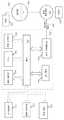
도 1은 광학 스택(101)을 포함하는 전형적인 컬러 어레이 패널(100)을 도시한다. 광학 스택(101)은 다음을 포함할 수 있지만, 이로 제한되지는 않는다:FIG. 1 illustrates a typical
i. 변환층(102);i. A
ii. 조명원들(104);ii.
iii. 반사기 표면(106);iii.
iv. 확산기층(108);iv. A
v. 광 재사용막(110);v. A light
vi. 광 변조층(112).vi.
(보는 사람의 입장에서 볼 때) 조명원들(104)의 앞에 배치된 변환층(102)은 양자 도트(quantum dot) 또는 형광 물질들(phosphor materials)을 포함할 수 있다. 양자 도트(예를 들면, 발광을 위해 양자 구속 효과를 이용하는 나노 크기의 입자들) 또는 형광 물질들은 변환층(102)을 형성하기 위해 광학층의 최상부 표면, 최하부 표면, 또는 양 표면들 상에 코팅되거나, 부착되거나, 도핑되거나, 또는 배치될 수 있다. 양자 도트 또는 형광 물질들은 또한 광학층 내에 내장될 수 있다. 이러한 물질들은 다양한 배치 방법들의 임의의 조합 또는 순서로 광학층에 배치될 수 있다.The
양자 도트 컬러 어레이들 또는 형광 컬러 어레이들을 이용하여, 변환층(102)은 컬러 디스플레이 시스템에 컬러들을 부여한다. 적색 양자 도트 또는 형광 물질은 녹색과 청색 광과 같은 더 높은 에너지들 또는 더 짧은 파장들의 광을 흡수하고 적색 광을 방출한다. 녹색 양자 도트 또는 형광 물질은 청색 광을 흡수하고 녹색 광을 방출한다. 따라서, 본 발명의 실시예와 같이, 변환층(102)은 원하는 컬러들을 생성하는데: 적색 및 녹색 광이 청색 광원으로부터 변환되고; 청색 광은 청색 광원으로부터 직접 방출된다.Using quantum dot color arrays or fluorescent color arrays, the
본 발명의 실시예에서, 변환층(102)은 디스플레이 디바이스의 활성 영역의 면적과 실질적으로 동일하게 되도록 폭과 높이에서 확장하는 단일 시트(또는, 대안적으로, 단일 평면을 형성하도록 배열된 다중 세그먼트들)이다. 예를 들어, 변환층(102)은 사선으로 약 4 인치, 10 인치, 32 인치, 40 인치, 50 인치, 58 인치 또는 그 이상일 수 있다. 부가적으로, 변환층(102)은 폭과 높이 사이에 16:9, 4:3, 3:2, 5:3, 5:4, 또는 1:1 등의 영상비(aspect ratio), 또는 비례 관계를 가질 수 있다. 도 1에 도시된 바와 같이, 변환층(102)은 조명원(104)으로부터 떨어져 배치된다. 본 발명의 대안의 실시예에서, 변환층(102)은 복수의 세그먼트들을 포함한다. 특정 실시예에서, 복수의 세그먼트들의 각 세그먼트는 단일 조명원(104)과 연관된다.In an embodiment of the present invention, the
조명원들(104)은 사람 또는 기계의 시력이 인지가능한 광을 생성하도록 변환층(102)에 의해 사용가능한 임의의 전자기 에너지원일 수 있다. 예를 들어, 조명원들(104)은 OLED, RGB LED, 광대역 LED, 청색 스펙트럼 LED, 자외선 스펙트럼 LED, 등의 하나 이상을 포함할 수 있다.The
이러한 조명원들(104)은 실질적으로 디스플레이 디바이스의 활성 영역의 길이와 높이로 확장하는 어레이로 배열될 수 있다. 조명원들(104) 사이의 피치(pitch) 밀도는 디스플레이의 픽셀 해상도와 동일하거나 이에 대응할 수 있다. 다시 말해, 픽셀의 수에 대한 조명원들(104)의 비는 1:1이 될 수 있다(예를 들면, 각각의 디스플레이 해상도에 대해 1920 x 1080, 3840 x 2160, 또는 7680 x 4320개의 조명원들). 이러한 경우에, 조명원들(104)의 각각의 위치는 (보는 사람의 입장에서 볼 때) 대응하는 픽셀의 뒤에 직접적으로 정렬될 수 있다. 다른 경우들에서, 조명원들(104)은 대응하는 픽셀로부터 또는 두 픽셀들 사이의 측면의 오프셋으로 배치될 수 있다. 조명원들(104) 사이의 피치는 균일하거나 불균일할 수 있는데, 예를 들여, 피치 밀도는 레터박스(letterbox) 포맷의 주변, 모서리들, 코너들, 또는 블랙 보더들에서보다 디스플레이의 중심 활성 영역 근처에서 더 높을 수 있다.These
다른 실시예들에서, 조명원들(104)과 픽셀의 수 사이의 비율은 1:2, 1:3, 1:4, 1:10, 또는 그 이상으로 낮아질 수 있다. 이러한 경우에, 백라이트 이미지의 해상도는 감소될 것이다. 대안적으로, 비율은 2:1, 3:1, 또는 그 이하로 더 높아질 수 있다. 예를 들어, 조명원이 픽셀이나 픽셀들의 그룹 대신, 서브픽셀과 연관될 수 있다.In other embodiments, the ratio between the number of
이러한 조명원들(104)은 개별적으로 제어되거나 또는, 대안적으로, 그들의 서브세트가 함께 집합적으로 제어될 수 있다. 개별적으로 제어가능한 조명원들(104)을 통한 백라이트 제어의 유연성은 로컬 디밍을 가능하게 한다. 로컬 디밍에 대한 부가적인 상세한 설명들은 사실상 그 전체가 참조로 여기에 포함되는, 발명의 명칭이 "Locally Dimmed Display"인 미국 특허 번호 8,277,056에서 볼 수 있다. 그러나, 조명원들(104)의 개별적인 제어에도 불구하고, 조명원들(104)의 각각에 대한 PSF는 복수의 픽셀들의 강도에 기여하기 위해 오버랩할 수 있다.These
도 1이 직접광(direct-lit) 백라이트 디스플레이를 도시하고 있지만, 에지광(edge-lit) 디스플레이가 또한 본 명세서에서 교시된 본 발명들의 이득들(예를 들면, PSF, 조명원 비닝(binning), 또는 온도 편차로부터의 컬러 시프트에 대한 보상)을 향유할 수 있다. 이러한 실시예에서, 하나 이상의 광원들에 의해 조명된 공간적 광 변조기가 공간적 광 변조기의 모서리에 위치된다. 에지광, 로컬 디밍에 대한 부가적인 상세한 설명들은 사실상 그 전체가 참조로 여기에 포함되는, 발명의 명칭이 "Edge Lit Locally Dimmed Display"인 미국 특허 번호 8,172,401에서 볼 수 있다.Although FIG. 1 illustrates a direct-lit backlight display, edge-lit displays may also be used to provide benefits (e.g., PSFs, binning, illumination, etc.) of the present invention taught herein, Or compensation for color shift from temperature deviation). In this embodiment, a spatial light modulator illuminated by one or more light sources is positioned at the edge of the spatial light modulator. Additional details on edge light, local dimming can be found in U.S. Patent No. 8,172,401, entitled " Edge Lit Locally Dimmed Display ", which is hereby incorporated by reference in its entirety in its entirety.
반사기 표면(106)은 미리 정해진 스펙트럼(예를 들면, 하나 이상의 원색들)을 반사하는 광대역 거울 표면, 색선별(dichroic) 거울 표면일 수 있다. 또한, 반사기 표면(106)은 조명원들(104)을 위한 쓰루-홀들(through-holes)을 포함할 수 있다. 이러한 쓰루-홀들은 구멍이 뚫리거나, 천공되거나, 또는 밀링될 수 있다. 반사기 표면(106)은 증가된 효율성을 위해 광학 스택(101)을 통해 광을 다시 재지향한다.The
도 1에서, 확산기층(108)은 다양한 방향들로 출사광을 산란시켜서 확산기(108)의 반대측 상에 위치된 보는 사람이 증가된 영역으로부터 기원하는 광을 인지하도록 한다. 일반적으로, 확산기(108)는 광을 수평 및 수직면들에서 상이한 각도 크기로 산란시킬 수 있다.In FIG. 1,
백라이팅의 광학 효율성을 증가시키기 위해 광 재사용막(110)이 사용된다. 일부 실시예들에서, 광 변조층(112)은 단지(또는 실질적으로 단지) 편광을 통과시킬 수 있으므로 백라이트는 반드시 비편광된 광을 생성한다. 반사형 편광기(예를 들면, 3M DBEF)가 광 변조층(112) 전의 마지막 광학층으로 사용될 수 있다. 그와 달리 흡수될 수 있는, 광 변조층(112)으로 입사한 잘못된 편광의 광은, 백라이트를 향해 광 재사용막(110)에 의해 다시 반사된다. 반사된 광은 편광화를 랜덤화하는 확산층(108)에서 산란된다. 정확한 편광화의 일부가 광 변조층(112)을 통해 통과하는 랜덤화된 편광화의 반사광은, 광학 스택에서 산란시키고 바운스함에 따라 광 변조층(112)을 향해 다시 보내질 수 있다.The
다른 광 재사용막(110)은 백라이트 유닛을 출사하는 광의 방향을 제어하도록 사용되는 프리즘 모양으로 구성된 막(예를 들면, 3M BEF)일 수 있다. 광 변조층(112)의 시야각 내의 광의 강도를 최대화하기 위하여, 시야각의 외부에 있는 광이 광학적 공동(cavity) 안으로 다시 반사될 수 있으며, 이는 산란 및 반사 후, 반사광의 일부가 시야각 내에 원하는 출사각을 갖도록 할 수 있다.The other
광 변조층(112)은 예를 들면, (i)투과형 광 변조기의 예가 되는 LCD 패널, (ii)반사형 광 변조기의 예가 되는 변형가능한 거울 디바이스(DMD), 또는 (iii)마이크로-전기-기계적 시스템(MEMS) 기반 변조기를 포함할 수 있다. 광 변조기(112)의 소자들은 디스플레이되는 이미지를 규정하는 데이터에 따라 제어된다.The
도 1은 광학 스택(101)의 실시예를 도시하고 있으며, 여기의 소자들의 배열은 변화할 수 있거나 또는 설명되지 않은 부가적인 소자들을 포함할 수 있다는 것이 인식되어야 한다. 예를 들어, 광 재사용막(110)이 확산기층(108)의 앞보다는 뒤에 배치될 수 있다. 또 다른 예에서, 변환층(102)은 조명원들(104) 뒤의 광학 스택(101) 내의 어디에라도 배치될 수 있다. 모든 이러한 변경들과 변화들이 본 명세서의 범위 내에 포함되는 것으로 의도된다.It should be appreciated that FIG. 1 illustrates an embodiment of an
여기서 발명자들에 의해 인식된 바와 같이, 전형적인 컬러 어레이 패널(100)은 "황색 꼬리 효과(yellow tail effect)", 또는 중심으로부터의 거리의 함수로 컬러들을 시프트하는 점 확산 함수(point spread function;PSF)를 겪는다. 다시 말해, 광원들에 가깝거나 그의 공간적 지역들로 다시 재지향된, 상대적으로 긴 광학 경로를 이동하는 광은, 넓은 각도들과 영역들로 공간적으로 확산될 수 있으며, 이는 - 특히 하나 이상의 반사들을 갖는 광 재사용으로 컬러 시프트(예를 들면, 황색 꼬리들)를 야기한다. 이러한 시스템에서, 예를 들어, 직접광의 발광기의 점 확산 함수의 중심에 있는 광은 일반적으로 변환될 것이지만, 거부된 광 구성성분들은 다시 바운스되어 발광기의 점 확산 함수의 중심으로부터 외주까지의 거리가 증가함에 따라 더 옅은 녹색과 적색으로 변환되어, 점 확산 함수(PSF)로 컬러 시프트가 일어나게 한다. PSF 꼬리는 PSF 중심이 원하는 백색 점을 가질 때라도 점점 황색(yellow)이 된다. 보상이 없을 때, 컬러 시프트 열화는 유난히 뚜렷해지거나 또는 시각적으로 눈에 잘 띄게 될 것이다. 도 2a, 도 2b 및 도 2c는 간단한 예시들로서 황색 꼬리 효과를 도시한다.As is recognized by the inventors herein, a typical
도 3은 디스플레이 시스템(300)의 디스플레이 논리의 전형적인 구성을 도시한다. 본 발명의 일부 가능한 실시예들에 따라, 디스플레이 시스템(300)은 백라이트(304)의 조명원들을 제어하기 위한 백라이트 제어 논리(302)를 포함한다. 이러한 조명원들은 도 1에 도시된 조명원들(104)과 동일하거나 유사할 수 있다. 백라이트 제어 논리(302)는 이미지 데이터 소스(도시되지 않음)(예를 들면, 셋탑 박스, 네트워킹된 서버, 저장 매체들 등)와 동작가능하게 결합될 수 있으며, 이미지 데이터 소스로부터 이미지 데이터를 수신하도록 구성된다. 내부 또는 외부 소스로부터의 이미지 데이터로부터 수신되거나 생성된 이미지 프레임들은 백라이트(304)를 구동하도록 백라이트 제어 논리(302)에 의해 사용될 수 있다. 예를 들어, 백라이트 제어 논리(302)는 하나 이상의 픽셀들 또는 서브픽셀들을 특정 강도로 조명하기 위해 백라이트(304)를 제어하도록 구성될 수 있다. 다양한 프레임들의 개별적 또는 집합적 구동값들을 다양한 해상도들로 유도하기 위하여 이미지 프레임들이 백라이트 제어 논리(302)에 의해 사용될 수 있다.3 shows a typical configuration of the display logic of the
본 발명의 이러한 실시예에서, 백라이트 제어 논리(302)는 광계 시뮬레이션 논리(306)와 논리적으로 결합된다. 광계 시뮬레이션 논리(306)는, 예를 들면, 황색 꼬리 효과, 조명원 비닝, 시스템 구성성분들에 대한 온도 의존성 등과 같은, 광계 상의 하나 이상의 영향들을 계산한다. 이러한 영향들에 기초하여, 광계 시뮬레이션 논리(306) 및/또는 변조기 제어 논리(308)(예를 들면, LCD 패널 제어 논리)는 개선된 화상 품질을 위해 이러한 영향들을 경감시킬 수 있다. 예를 들어, 황색 꼬리 효과를 경감시키기 위하여, 변조기(310)(예를 들면, LCD 패널)에 대한 구동 값들이 더 짙은 청색이 되도록 바이어스될 수 있다.In this embodiment of the invention, the
일 실시예에서, 광계 시뮬레이션은 3원색들의 각각에 대한 3개의 컬러 삼자극 값들을 나타내는 9개의 컨벌루션 채널들을 사용할 수 있다. 그러나, 이는 계산을 위한 비용이 많이 든다. 대안으로서, 광계 시뮬레이션은 개별적으로 제어가능한 백라이트의 조명원들을 광대역 광 스펙트럼 구성성분들에 대해서는 제 1 PSF를 갖고 황색 광 스펙트럼 구성성분들에 대해서는 제 2 PSF를 갖도록 - 또는 9개가 아닌 두개의 컨벌루션 채널들을 갖도록 모델링할 수 있다. 제 1 PSF는 황색 꼬리 효과로부터 제 2 PSF를 오버랩하는 것보다 좁아진다.In one embodiment, the porthole simulation may use nine convolution channels representing three color tri-stimulus values for each of the three primary colors. However, this is expensive to calculate. Alternatively, the pumped-field simulation may be performed by using light sources of individually controllable backlights such that they have a first PSF for broadband optical spectral components and a second PSF for yellow light spectral components-or two non-nine convolutional channels . ≪ / RTI > The first PSF is narrower than the yellow tail effect and overlaps the second PSF.
광계 시뮬레이션 논리(306)는 백라이트 LED들(예를 들면, 조명원들(102))의 비닝(그의 부족 또는 불충분함)을 보상하기 위한 컨벌루션 채널을 포함할 수 있다. 광대역 백라이트를 위하여, 청색 LED 다이들과 황색 형광체(예를 들면, YAG 형광체)로 구성된 백색 LED들이 사용될 수 있다. 그러나, 넓은 성능 범위들을 갖는 백색 LED들의 비닝 편차는 디스플레이 정밀성과 균일성을 감소시킬 수 있다. 특히, 각각의 청색 LED 다이 상의 황색 형광 물질은 상이한 백색 점을 유발하도록 변화할 수 있다. 각 청색 LED 다이 상의 황색 형광체는 또한 다양한 스펙트럼 방출을 가질 수 있다. 유사하게, 백라이팅으로서 UV 및/또는 청색 스펙트럼 구성성분들을 배타적으로 사용하는 실시예에서, 이러한 UV 또는 청색 LED들은 일정한 전력을 위해 상이한 강도를 가질 수 있거나 또는 방출 스펙트럼들에서 변화할 수 있다.Pumped
본 발명의 실시예로써, 부가적인 컨벌루션 채널들에 대한 디스플레이 성능의 온도 의존성을 보상하기 위해 광계 시뮬레이션 논리(306)가 사용될 수 있다. 예를 들어, 개별적으로 또는 집합적으로 조명원들 또는 변환층의 온도 의존성을 설명하기 위해 감소 함수(들)이 사용될 수 있다. 다른 예로써, 온도 의존 점 확산 함수가 광학 시트 왜곡을 해결하기 위해 사용될 수 있다. 특정 실시예에서, (광학 스택 내에 배치된) 하나 이상의 센서들로부터 하나 이상의 온도가 취해질 수 있거나 디스플레이 특성(예를 들면, 시간에 따른 성능 변화)에 의해 온도가 추론될 수 있다.As an embodiment of the present invention, pumped
도 4는 로컬 디밍 디스플레이를 구동하기 위한 전형적인 흐름도(400)를 도시한다. 단계(402)에서, 백라이트(예를 들면, 조명원들(104))를 위한 구동 신호들이 생성될 수 있다. 구동된 백라이트는 단계(404)에서 제 1 광을 생성한다. 제 1 광은 광대역 광(예를 들면, 백색 광), UV 스펙트럼 구성성분들, 청색 스펙트럼 구성성분들, 또는 스펙트럼의 임의의 부분일 수 있다. 단계(406)에서 도시된 바와 같이, 제 1 광은 제 2 광으로 변환된다. 예를 들어, 제 1 광을 수신하는 변환층이 원하는 컬러들(예를 들면, 적색 또는 녹색 광)을 가진 제 2 광을 생성한다.4 shows an
다음, 단계(408)에서, 변조기(예를 들면, LCD 패널), 바람직하게는 각 원색에 대한 서브픽셀 변조기를 위한 구동 값들이 입력 이미지 데이터에 기초하여 생성된다. 단계(412)에 반영된 것과 같이, 변조기 구동 값들을 조정, 변경 또는 가중하기 위해 하나 이상의 광계 시뮬레이션들의 결과들이 사용될 수 있다. 보상을 위한 하나 이상의 광계 시뮬레이션들이 단계(410)에서 수행된다. 여기서 설명되는 것과 같이, 광계 시뮬레이션들은 예들로써, (i)백라이트 점 확산 함수의 함수인 컬러 시프트들, (ii)백라이트의 하나 이상의 조명원들 중 하나의 조명원의 성능 특성과 백라이트의 성능 특성 사이의 차이, (iii)성능에 대한 온도 분산, 또는 (iv)그의 조합들을 해결할 수 있다.Next, at
여기서 설명된 흐름도(400)는 예시적인 목적들만을 위한 것이며, 광의 다양한 변경들 또는 변화들이 당업자들에게 제시될 것임이 인식된다. 대안의 구현들에서, 흐름도(400)에 기재된 단계들은 도 4에 기재된 순서와 다르게 실행될 수 있으며, 부가적인 단계들을 포함할 수 있고, 및/또는 일부 단계들을 완전히 생략할 수 있다. 예를 들어, 단계들(402 및 408)은 사실상 실질적으로 동시에 실행될 수 있거나 또는 반대 순서로 실행될 수 있다. 다른 예로써, 단계(410)는 단계(404) 전에 수행될 수 있다. 모든 이러한 변경들 및 변화들은 본 명세서의 범주 내에 포함되는 것으로 의도된다.It is appreciated that the
실시예들은 프로세서를 포함하고 이하로 논의된 바와 같은 전술한 방법들 중 임의의 것을 수행하도록 구성된 장치를 포함한다.Embodiments include a processor and an apparatus configured to perform any of the methods described above as discussed below.
실시예들은 하나 이상의 프로세서들에 의해 수행될 때 이하에 논의된 바와 같은 전술한 방법들 중 임의의 것이 수행되도록 하는 소프트웨어 명령들을 포함하는, 컴퓨터 판독가능한 저장 매체를 포함한다.Embodiments include a computer readable storage medium having software instructions that, when executed by one or more processors, cause any of the aforementioned methods, such as those discussed below, to be performed.
구현 메커니즘들-하드웨어 개관Implementation Mechanisms - Hardware Overview
일 실시예에 따라, 여기서 설명된 기술들이 하나 이상의 특수 목적 컴퓨팅 디바이스들에 의해 수행된다. 특수 목적 컴퓨팅 디바이스들은 기술들을 실행하기 위해 고정 배선될 수 있거나, 또는 기술들을 실행하기 위해 지속적으로 프로그램되는 하나 이상의 애플리케이션-특정 집적 회로들(ASIC들) 또는 필드 프로그래머블 게이트 어레이들(FPGA들)과 같은 디지털 전기 디바이스들을 포함할 수 있거나, 또는 펌웨어, 메모리, 다른 저장장치, 또는 그 조합의 프로그램 명령들에 따라 기술들을 실행하도록 프로그램된 하나 이상의 범용 하드웨어 프로세서들을 포함할 수 있다. 이러한 특수 목적 컴퓨팅 디바이스들은 또한 기술들을 완성하기 위하여 주문형 고정 배선된 논리, ASIC들, 또는 FPGA들을 주문형 프로그래밍과 조합할 수 있다. 특수 목적 컴퓨팅 디바이스들은 데스크탑 컴퓨터 시스템들, 휴대용 컴퓨터 시스템들, 핸드헬드 디바이스들, 네트워킹 디바이스들 또는 기술들을 수행하도록 고정 배선된 및/또는 프로그램된 논리를 통합하는 임의의 다른 디바이스일 수 있다.According to one embodiment, the techniques described herein are performed by one or more special purpose computing devices. Special purpose computing devices may be hardwired to execute the techniques or may be implemented as one or more application-specific integrated circuits (ASICs) or field programmable gate arrays (FPGAs) that are continuously programmed to execute the techniques Digital electrical devices, or may comprise one or more general purpose hardware processors programmed to execute the techniques in accordance with program instructions in firmware, memory, other storage, or a combination thereof. These special purpose computing devices may also combine custom hardwired logic, ASICs, or FPGAs with on-demand programming to complete the techniques. Special purpose computing devices may be desktop computer systems, portable computer systems, handheld devices, networking devices, or any other device that incorporates hardwired and / or programmed logic to perform the techniques.
예를 들어, 도 5는 본 발명의 실시예가 수행될 수 있는 컴퓨터 시스템(500)을 도시하는 블록도이다. 컴퓨터 시스템(500)은 정보를 통신하기 위한 버스(502) 또는 다른 통신 메커니즘과, 정보를 처리하기 위해 버스(502)와 결합된 하드웨어 프로세서(504)를 포함한다. 하드웨어 프로세서(504)는 예를 들면, 범용 마이크로프로세서일 수 있다.For example, FIG. 5 is a block diagram illustrating a
컴퓨터 시스템(500)은 또한, 정보와 프로세서(504)에 의해 실행될 명령들을 저장하기 위해 버스(502)에 결합된 랜덤 액세스 메모리(RAM) 또는 다른 동적 저장 디바이스와 같은 메인 메모리(506)를 포함한다. 메인 메모리(506)는 또한 프로세서(504)에 의해 실행될 명령들의 실행 동안 임시적인 변수들 또는 다른 중간 정보를 저장하는데 사용될 수 있다. 프로세서(504)로 액세스가능한 저장 매체들에 저장될 때, 이러한 명령들은 컴퓨터 시스템(500)을 명령들에 특정된 동작들을 수행하도록 주문형 맞춤되는 특수 목적 머신으로 랜더링한다.The
컴퓨터 시스템(500)은 또한 프로세서(504)를 위한 정적 정보 및 명령들을 저장하기 위해 버스(502)에 결합된 판독 전용 메모리(ROM)(508) 또는 다른 정적 저장 디바이스를 포함한다. 정보 및 명령들을 저장하기 위해 자기 디스크 또는 광학 디스크와 같은 저장 디바이스(510)가 제공되고 버스(502)에 결합된다.The
컴퓨터 시스템(500)은 정보를 컴퓨터 사용자에게 디스플레이하기 위해 액정 디스플레이(LCD)와 같은 디스플레이(512)에 버스(502)를 통해 결합될 수 있다. 글자와 숫자 및 다른 키들을 포함하는 입력 디바이스(514)가 정보 및 명령 선택들을 프로세서(504)에 통신하기 위해 버스(502)에 결합된다. 다른 형태의 사용자 입력 디바이스는 방향 정보와 명령 선택들을 프로세서(504)에 통신하고 디스플레이(512) 상에서 커서의 움직임을 제어하기 위한 마우스, 트랙볼, 또는 커서 방향 키들과 같은 커서 제어(516)이다. 이러한 입력 디바이스는 전형적으로, 디바이스를 평면의 위치들에 지정할 수 있도록 하는, 제 1 축(예를 들면, x)과 제 2 축(예를 들면, y)의 2개의 축들에서 2 자유도들을 가진다.The
컴퓨터 시스템(500)은, 컴퓨터 시스템과 결합하여 컴퓨터 시스템(500)이 특수 목적 머신이 되도록 하거나 프로그래밍하는 주문형 고정 배선 논리, 하나 이상의 ASIC들 또는 FPGA들, 펌웨어 및/또는 프로그램 논리를 이용하여 여기서 설명된 기술들을 실행할 수 있다. 일 실시예에 따라서, 여기의 기술들은 메인 메모리(506)에 포함된 하나 이상의 명령들의 하나 이상의 시퀀스들을 실행하는 프로세서(504)에 응답하여 컴퓨터 시스템(500)에 의해 수행된다. 이러한 명령들은 저장 디바이스(510)와 같은 다른 저장 매체로부터 메인 메모리(506)로 판독될 수 있다. 메인 메모리(506)에 포함된 명령들의 시퀀스들의 실행은 프로세서(504)가 여기서 설명된 프로세스 단계들을 수행하게 한다. 대안의 실시예들에서, 고정 배선 회로가 소프트웨어 명령들 대신 또는 그들과 결합하여 사용될 수 있다.The
여기서 사용되는 것과 같은 "저장 매체들"이라는 용어는 머신이 특정 방식으로 동작하도록 하는 데이터 및/또는 명령들을 저장하는 임의의 매체들을 나타낸다. 이러한 저장 매체들은 비휘발성 매체들 및/또는 휘발성 매체들을 포함할 수 있다. 비휘발성 매체들은 예를 들면, 저장 디바이스(510)와 같은, 광학 또는 자기 디스크들을 포함한다. 휘발성 매체들은 메인 메모리(506)와 같은, 동적 메모리를 포함한다. 저장 매체들의 공통 형태들은 예를 들면, 플로피 디스크, 플렉시블 디스크, 하드 디스크, 고체 상태 드라이브, 자기 테이프, 또는 임의의 다른 자기 데이터 저장 매체, CD-ROM, 임의의 다른 광학 데이터 저장 매체, 구멍들의 패턴들을 갖는 임의의 물리적 매체, RAM, PROM, 및 EPROM, FLASH-EPROM, NVRAM, 임의의 다른 메모리 칩 또는 카트리지를 포함한다.The term "storage media ", as used herein, refers to any medium that stores data and / or instructions that cause the machine to operate in a particular manner. Such storage media may include non-volatile media and / or volatile media. Non-volatile media include optical or magnetic disks, such as, for example,
저장 매체들은 송신 매체들과는 떨어져 있으나 그와 함께 사용될 수 있다. 송신 매체들은 저장 매체들 사이에서 정보를 전송하는데 참여한다. 예를 들어, 송신 매체들은 버스(502)를 포함하는 배선들을 포함하여, 동축 케이블들, 구리 배선 및 광섬유들을 포함한다. 송신 매체들은 또한 라디오파 및 적외선 데이터 통신들 동안 생성되는 것과 같은, 음파 또는 광파들의 형태를 가질 수 있다.The storage media may be separate from, but may be used with, the transmission media. Transmission media participate in transferring information between storage media. For example, the transmission mediums include coaxial cables, copper interconnects, and optical fibers, including
다양한 형태들의 매체들이 하나 이상의 명령들의 하나 이상의 시퀀스들을 실행을 위해 프로세서(504)로 전달하는데 관여될 수 있다. 예를 들어, 명령들은 처음에 원격 컴퓨터의 자기 디스크 또는 고체 상태 드라이브 상에서 전달될 수 있다. 원격 컴퓨터는 명령들을 그의 동적 메모리로 로드할 수 있고 명령들을 모뎀을 이용하여 전화선을 통해 보낼 수 있다. 컴퓨터 시스템(500)에 가까운 모뎀은 전화선 상에서 데이터를 수신할 수 있고 데이터를 적외선 신호로 변환하는데 적외선 송신기를 이용할 수 있다. 적외선 검출기가 적외선 신호로 전달된 데이터를 수신할 수 있고 적절한 회로가 데이터를 버스(502) 상에 위치시킬 수 있다. 버스(502)는 프로세서(504)가 그로부터 명령들을 검색하고 실행하는 메인 메모리(506)로 데이터를 전달한다. 메인 메모리(506)에 의해 수신된 명령들은 선택적으로 프로세서(504)에 의한 실행 전 또는 후에 저장 디바이스(510) 상에 저장될 수 있다.Various forms of media may be involved in communicating one or more sequences of one or more instructions to the
컴퓨터 시스템(500)은 또한 버스(502)에 결합된 통신 인터페이스(518)를 포함한다. 통신 인터페이스(518)는 로컬 네트워크(522)에 연결되는 네트워크 링크(520)에 결합하는 양방향 데이터 통신을 제공한다. 예를 들어, 통신 인터페이스(518)는 통합된 서비스 디지털 네트워크(ISDN) 카드, 케이블 모뎀, 위성 모뎀, 또는 대응하는 타입의 전화선에 데이터 통신 연결을 제공하기 위한 모뎀일 수 있다. 다른 예로써, 통신 인터페이스(518)는 데이터 통신 연결을 호환성 LAN에 제공하기 위한 로컬 영역 네트워크(LAN) 카드일 수 있다. 무선 링크들이 또한 구현될 수 있다. 임의의 이러한 구현에서, 통신 인터페이스(518)는 다양한 타입들의 정보를 표현하는 디지털 데이터 스트림들을 전달하는 전기, 전자기 또는 광 신호들을 송신하고 수신한다.The
네트워크 링크(520)는 전형적으로 하나 이상의 네트워크들을 통해 다른 데이터 디바이스들에 데이터 통신을 제공한다. 예를 들어, 네트워크 링크(520)는 로컬 네트워크(522)를 통해 호스트 컴퓨터(524)로 또는 인터넷 서비스 제공자(ISP)(526)에 의해 운영되는 데이터 장치로 연결을 제공할 수 있다. ISP(526)는 차례로 데이터 통신 서비스들을 현재 일반적으로 "인터넷"(528)으로 불리는 세계 각지의 패킷 데이터 통신 네트워크를 통해 공급한다. 로컬 네트워크(522)와 인터넷(528)은 둘다 디지털 데이터 스트림들을 전달하는 전기, 전자기 또는 광 신호들을 사용한다. 디지털 데이터를 컴퓨터 시스템(500)으로 및 컴퓨터 시스템으로부터 디지털 데이터를 전달하는, 다양한 네트워크들을 통한 신호들과 네트워크 링크(520) 상의 통신 인터페이스(518)를 통하는 신호들은 전송 매체들의 예시적인 형태들이다.The network link 520 typically provides data communication to other data devices via one or more networks. For example, the network link 520 may provide a connection to the
컴퓨터 시스템(500)은 네트워크(들), 네트워크 링크(520) 및 통신 인터페이스(518)를 통해 메시지들을 보내고 프로그램 코드를 포함하는 데이터를 수신할 수 있다. 인터넷 예에서, 서버(530)는 인터넷(528), ISP(526), 로컬 네트워크(522) 및 통신 인터페이스(518)를 통해 응용 프로그램에 대한 요청된 코드를 송신할 수 있다. 수신된 코드는 그가 수신될 때, 프로세서(504)에 의해 실행될 수 있으며, 및/또는 나중 실행을 위해 저장 디바이스(510), 또는 다른 비휘발성 저장장치에 수신, 및/또는 저장될 수 있다.
동등물들, 확장들, 대안들 및 기타Equivalents, extensions, alternatives and others
전술한 명세에서, 본 발명의 가능한 실시예들이 실행마다 변화할 수 있는 다양한 특정의 상세한 설명들을 참조하여 설명되었다. 따라서, 발명이 무엇인지, 그리고 무엇이 출원인들에 의해 발명으로 의도되는지에 대한 유일하고 배타적인 지시자는 본 출원으로부터 발행한 청구항들의 세트이며, 이러한 청구항들이 발행하는 특정 형식은 임의의 다음 교정을 포함한다. 따라서, 청구항에 명시적으로 기재되지 않은 제한, 소자, 특징, 특성, 장점 또는 태도는 어떠한 방식으로도 이러한 청구항의 범주를 제한해선 안된다. 따라서, 명세서와 도면들은 제한적인 의도보다는 예시적인 것으로 간주된다. 본 발명의 다양한 변경들과 변화들이 상기 교시들의 입장에서 가능하다.In the foregoing specification, possible embodiments of the invention have been described with reference to various specific details that may vary from execution to execution. Thus, the only exclusive indication of what the invention is and what is intended by the applicants is a set of claims issued from this application, and the particular form in which those claims are issued includes any subsequent proofs . Accordingly, the limitations, elements, features, characteristics, advantages or attitudes not expressly stated in the claims should not be construed as limiting the scope of such claims in any way. Accordingly, the specification and drawings are to be regarded in an illustrative rather than a restrictive sense. Various modifications and variations of the present invention are possible in light of the above teachings.
이러한 청구항들에 포함된 용어들에 대하여 여기서 명시적으로 개시되는 임의의 정의들은 이러한 용어들이 청구항들에서 사용되는 의미를 정의할 것이다. 명확성을 위해, 예컨대(exempli gratia;e.g.)는 "예시를 위하여(for the sake of example)"(완전하지 않은)를 의미하며, 이는 즉(id est;i.e.) 또는 "즉(that is)"과는 다르다는 것이 또한 이해되어야 한다.Any definitions explicitly set forth herein with respect to terms included in such claims shall define the meanings in which such terms are used in the claims. For clarity, for example, gratia (eg) means "for the sake of example" (not complete), which means (id est; ie) or "that is" It is also to be understood that they are different.
101: 광학 스택 102: 변환층
112: 광 변조층 302: 백라이트 제어 논리
306: 광계 시뮬레이션 논리 310: 변조기101: optical stack 102: conversion layer
112: optical modulation layer 302: backlight control logic
306: Pumice simulation logic 310: Modulator
Claims (5)
Translated fromKorean제 1 광을 방출하도록 구성된 백라이트의 하나 이상의 조명원들로서, 상기 제 1 광은 UV 스펙트럼 구성성분들 또는 청색광 스펙트럼 구성성분들 중 적어도 하나를 포함하는, 상기 하나 이상의 조명원들과;
상기 제 1 광에 의해 자극되고 상기 제 1 광과 재사용된 광의 적어도 일부를 제 2 광으로 변환시키도록 구성된 하나 이상의 광 변환층들로서, 양자 도트들 또는 형광 물질들을 포함하는, 상기 하나 이상의 광 변환층들과;
상기 디스플레이 시스템의 개별적인 서브픽셀들을 통해 투과하는 광을 변조시키도록 구성된 하나 이상의 광 변조기들과;
백라이트 점 확산 함수의 함수로서 컬러 시프트들을 계산하는 논리와;
상기 논리에 기초하여 상기 하나 이상의 광 변조기들에 대한 구동값들을 조절하기 위한 제어기를 포함하는, 디스플레이 시스템.A display system comprising:
At least one illumination source of a backlight configured to emit a first light, wherein the first light comprises at least one of UV spectral components or blue light spectral components;
Wherein the at least one light conversion layer is configured to convert at least a portion of the first light and the reused light, which is stimulated by the first light, to second light, the quantum dots or fluorescent materials. ;
One or more optical modulators configured to modulate light transmitted through individual sub-pixels of the display system;
Logic for computing color shifts as a function of the backlight point spread function;
And a controller for adjusting drive values for the one or more optical modulators based on the logic.
상기 백라이트의 상기 하나 이상의 조명원들의 조명원의 성능 특성과 상기 백라이트의 성능 특성 사이의 차이를 계산하는 논리를 포함하는, 디스플레이 시스템.The method according to claim 1,
And computing the difference between a performance characteristic of the illumination source of the one or more illumination sources of the backlight and a performance characteristic of the backlight.
랜더링된 픽셀에 대한 온도 분산 중 적어도 하나를 계산하는 논리를 포함하는, 디스플레이 시스템.The method according to claim 1,
And calculating at least one of a temperature variance for the rendered pixel.
상기 백라이트의 상기 성능 특성은 상기 백라이트의 복수의 조명원들의 평균(average), 산술 평균(mean), 및 중앙값(median) 성능 중 적어도 하나인, 디스플레이 시스템.The method according to claim 1,
Wherein the performance characteristic of the backlight is at least one of an average, an arithmetic mean, and a median performance of a plurality of illumination sources of the backlight.
상기 성능 특성은 평균 전역(average gamut)인, 디스플레이 시스템.5. The method of claim 4,
Wherein the performance characteristic is an average gamut.
Applications Claiming Priority (3)
| Application Number | Priority Date | Filing Date | Title |
|---|---|---|---|
| US201361775375P | 2013-03-08 | 2013-03-08 | |
| US61/775,375 | 2013-03-08 | ||
| PCT/US2014/016212WO2014137565A1 (en) | 2013-03-08 | 2014-02-13 | Techniques for dual modulation display with light conversion |
Related Parent Applications (1)
| Application Number | Title | Priority Date | Filing Date |
|---|---|---|---|
| KR1020147027340ADivisionKR101563143B1 (en) | 2013-03-08 | 2014-02-13 | Techniques for dual modulation display with light conversion |
Related Child Applications (1)
| Application Number | Title | Priority Date | Filing Date |
|---|---|---|---|
| KR1020207014285ADivisionKR102178411B1 (en) | 2013-03-08 | 2014-02-13 | Techniques for dual modulation display with light conversion |
Publications (2)
| Publication Number | Publication Date |
|---|---|
| KR20150117203Atrue KR20150117203A (en) | 2015-10-19 |
| KR102115146B1 KR102115146B1 (en) | 2020-05-26 |
Family
ID=51491767
Family Applications (4)
| Application Number | Title | Priority Date | Filing Date |
|---|---|---|---|
| KR1020207014285AActiveKR102178411B1 (en) | 2013-03-08 | 2014-02-13 | Techniques for dual modulation display with light conversion |
| KR1020147027340AActiveKR101563143B1 (en) | 2013-03-08 | 2014-02-13 | Techniques for dual modulation display with light conversion |
| KR1020147027437AActiveKR102115146B1 (en) | 2013-03-08 | 2014-02-13 | Techniques for dual modulation display with light conversion |
| KR1020207032334AActiveKR102250809B1 (en) | 2013-03-08 | 2014-02-13 | Techniques for dual modulation display with light conversion |
Family Applications Before (2)
| Application Number | Title | Priority Date | Filing Date |
|---|---|---|---|
| KR1020207014285AActiveKR102178411B1 (en) | 2013-03-08 | 2014-02-13 | Techniques for dual modulation display with light conversion |
| KR1020147027340AActiveKR101563143B1 (en) | 2013-03-08 | 2014-02-13 | Techniques for dual modulation display with light conversion |
Family Applications After (1)
| Application Number | Title | Priority Date | Filing Date |
|---|---|---|---|
| KR1020207032334AActiveKR102250809B1 (en) | 2013-03-08 | 2014-02-13 | Techniques for dual modulation display with light conversion |
Country Status (11)
| Country | Link |
|---|---|
| US (3) | US9940881B2 (en) |
| EP (1) | EP2965308B1 (en) |
| JP (2) | JP6081618B2 (en) |
| KR (4) | KR102178411B1 (en) |
| CN (2) | CN110060640B (en) |
| BR (2) | BR122017001987B1 (en) |
| ES (1) | ES2830248T3 (en) |
| IN (1) | IN2015KN02736A (en) |
| PL (1) | PL2965308T3 (en) |
| RU (2) | RU2744992C2 (en) |
| WO (1) | WO2014137565A1 (en) |
Families Citing this family (17)
| Publication number | Priority date | Publication date | Assignee | Title |
|---|---|---|---|---|
| WO2012082825A2 (en)* | 2010-12-17 | 2012-06-21 | Dolby Laboratories Licensing Corporation | Quantum dots for display panels |
| KR102118309B1 (en) | 2012-09-19 | 2020-06-03 | 돌비 레버러토리즈 라이쎈싱 코오포레이션 | Quantum dot/remote phosphor display system improvements |
| BR122017001987B1 (en) | 2013-03-08 | 2022-04-05 | Dolby Laboratories Licensing Corporation | Visualization system and apparatus for monitor techniques with dual modulation with light conversion |
| CN111243533B (en) | 2014-03-26 | 2022-11-25 | 杜比实验室特许公司 | Global light compensation in various displays |
| EP3633663B1 (en)* | 2014-08-21 | 2024-06-19 | Dolby Laboratories Licensing Corporation | Techniques for dual modulation with light conversion |
| JP2016133640A (en)* | 2015-01-20 | 2016-07-25 | キヤノン株式会社 | Display device and control method thereof |
| US10261330B2 (en) | 2015-08-25 | 2019-04-16 | Christie Digital Systems Usa, Inc. | System for producing an output light beam of a given spectrum |
| WO2017053350A1 (en) | 2015-09-21 | 2017-03-30 | Dolby Laboratories Licensing Corporation | Techniques for operating a display in the perceptual code space |
| EP3147893B1 (en)* | 2015-09-24 | 2021-06-09 | Dolby Laboratories Licensing Corporation | Light field simulation techniques for dual modulation |
| US10210820B2 (en) | 2016-02-03 | 2019-02-19 | Canon Kabushiki Kaisha | Image display apparatus and method for controlling same |
| JP6859090B2 (en)* | 2016-02-03 | 2021-04-14 | キヤノン株式会社 | Image display device and its control method |
| US10304396B2 (en)* | 2016-10-28 | 2019-05-28 | Himax Display, Inc. | Image processing method for alleviating tailing phenomenon and related imaging processing circuit and display apparatus |
| US10607551B2 (en) | 2017-03-21 | 2020-03-31 | Dolby Laboratories Licesing Corporation | Temperature-compensated LED-backlit liquid crystal displays |
| US11295680B2 (en)* | 2019-04-11 | 2022-04-05 | PixelDisplay, Inc. | Method and apparatus of a multi-modal illumination and display for improved color rendering, power efficiency, health and eye-safety |
| JP7500966B2 (en) | 2019-12-24 | 2024-06-18 | セイコーエプソン株式会社 | CIRCUIT DEVICE, DISPLAY DEVICE, ELECTRONIC INSTRUMENT, MOBILE OBJECT, AND CONTROL METHOD |
| CN111707455B (en)* | 2020-07-03 | 2021-08-13 | 深圳爱克莱特科技股份有限公司 | Smooth dimming method and system for lamp |
| CN114203093B (en)* | 2021-12-23 | 2022-10-11 | 长沙惠科光电有限公司 | Display panel color cast compensation method, display module and electronic equipment |
Citations (7)
| Publication number | Priority date | Publication date | Assignee | Title |
|---|---|---|---|---|
| US801871A (en)* | 1904-08-02 | 1905-10-17 | Carl Herminghaus | Dyer's jigger. |
| US20090322800A1 (en)* | 2008-06-25 | 2009-12-31 | Dolby Laboratories Licensing Corporation | Method and apparatus in various embodiments for hdr implementation in display devices |
| KR20110105009A (en)* | 2009-01-21 | 2011-09-23 | 돌비 레버러토리즈 라이쎈싱 코오포레이션 | Apparatus and Methods for Color Displays |
| KR20110128853A (en)* | 2009-02-11 | 2011-11-30 | 톰슨 라이센싱 | Signal Generation for LED / LCD-Based High Dynamic Range Displays |
| JP2012500996A (en)* | 2008-08-30 | 2012-01-12 | シャープ株式会社 | Method and system for reducing viewing angle induced color shift |
| US20120038286A1 (en)* | 2010-08-13 | 2012-02-16 | Ghulam Hasnain | Drive circuit for a color temperature tunable led light source |
| KR20120127190A (en)* | 2011-05-13 | 2012-11-21 | 삼성디스플레이 주식회사 | Display apparatus, method of displaying an image using the same and method of manufacturing the same |
Family Cites Families (168)
| Publication number | Priority date | Publication date | Assignee | Title |
|---|---|---|---|---|
| DE3581546D1 (en) | 1984-03-12 | 1991-03-07 | Matsushita Electric Industrial Co Ltd | OPTICAL FILTER AND PRODUCTION METHOD. |
| JPH0278393A (en) | 1988-09-14 | 1990-03-19 | Hitachi Ltd | Stereoscopic color picture display device |
| JPH0341890A (en) | 1989-07-07 | 1991-02-22 | Pioneer Electron Corp | Beam index type color display device |
| EP0884914A1 (en) | 1993-02-03 | 1998-12-16 | Nitor | Methods and apparatus for image projection |
| JP3187669B2 (en) | 1994-04-01 | 2001-07-11 | 日本碍子株式会社 | Display element and display device |
| US5737045A (en) | 1995-09-22 | 1998-04-07 | Ois Optical Imaging Systems, Inc. | LCD with notch filter |
| US5754159A (en) | 1995-11-20 | 1998-05-19 | Texas Instruments Incorporated | Integrated liquid crystal display and backlight system for an electronic apparatus |
| KR100286828B1 (en) | 1996-09-18 | 2001-04-16 | 니시무로 타이죠 | Flat panel display device |
| JP3787983B2 (en) | 1997-06-18 | 2006-06-21 | セイコーエプソン株式会社 | Optical switching element, image display device, and projection device |
| US6864626B1 (en) | 1998-06-03 | 2005-03-08 | The Regents Of The University Of California | Electronic displays using optically pumped luminescent semiconductor nanocrystals |
| US20050146258A1 (en) | 1999-06-02 | 2005-07-07 | Shimon Weiss | Electronic displays using optically pumped luminescent semiconductor nanocrystals |
| EP1042775A2 (en) | 1998-09-22 | 2000-10-11 | Fed Corporation | Inorganic-based color conversion matrix element for organic color display devices and method of fabrication |
| JP2001265296A (en) | 2000-01-14 | 2001-09-28 | Sharp Corp | Transmission type liquid crystal display device and image processing method |
| GB2379317A (en) | 2001-08-30 | 2003-03-05 | Cambridge Display Tech Ltd | Optoelectronic display operating by photoluminescence quenching |
| US7015991B2 (en) | 2001-12-21 | 2006-03-21 | 3M Innovative Properties Company | Color pre-filter for single-panel projection display system |
| WO2003058726A1 (en) | 2001-12-28 | 2003-07-17 | Sanken Electric Co., Ltd. | Semiconductor light-emitting device, light-emitting display, method for manufacturing semiconductor light-emitting device, and method for manufacturing light-emitting display |
| JP2003346530A (en) | 2002-05-23 | 2003-12-05 | Nippon Sheet Glass Co Ltd | Planar light source and image scanner |
| US7003461B2 (en) | 2002-07-09 | 2006-02-21 | Renesas Technology Corporation | Method and apparatus for an adaptive codebook search in a speech processing system |
| WO2004010406A2 (en) | 2002-07-23 | 2004-01-29 | Koninklijke Philips Electronics N.V. | Electroluminescent display, electronic device comprising such a display and method of manufacturing an electroluminescent display |
| US20060007194A1 (en)* | 2002-09-12 | 2006-01-12 | Koninklijke Philips Electronics N.C. | Transflective liquid crystal display with reduced flicker |
| KR100712334B1 (en) | 2002-09-30 | 2007-05-02 | 엘지전자 주식회사 | How to adjust the brightness level of the liquid crystal display |
| US7430022B2 (en) | 2002-10-01 | 2008-09-30 | Koninklijke Philips Electronics N.V. | Color display device |
| JP4087681B2 (en) | 2002-10-29 | 2008-05-21 | 株式会社日立製作所 | LIGHTING DEVICE AND DISPLAY DEVICE USING THE SAME |
| CN100493280C (en) | 2002-12-26 | 2009-05-27 | 皇家飞利浦电子股份有限公司 | Color temperature correction of phosphor converted light emitting diodes |
| JP2004325647A (en) | 2003-04-23 | 2004-11-18 | Sharp Corp | Display element |
| EP1640787B1 (en) | 2003-06-20 | 2009-04-01 | Sharp Kabushiki Kaisha | Display |
| DE602004031427D1 (en) | 2003-07-22 | 2011-03-31 | Ngk Insulators Ltd | MEMBER ELEMENT AND DEVICE WITH CONTROLLER ELEMENT |
| US7052152B2 (en) | 2003-10-03 | 2006-05-30 | Philips Lumileds Lighting Company, Llc | LCD backlight using two-dimensional array LEDs |
| US7354172B2 (en) | 2004-03-15 | 2008-04-08 | Philips Solid-State Lighting Solutions, Inc. | Methods and apparatus for controlled lighting based on a reference gamut |
| JP4139344B2 (en) | 2004-03-15 | 2008-08-27 | シャープ株式会社 | Display device |
| US7768023B2 (en) | 2005-10-14 | 2010-08-03 | The Regents Of The University Of California | Photonic structures for efficient light extraction and conversion in multi-color light emitting devices |
| DK1779362T3 (en) | 2004-07-27 | 2016-06-27 | Dolby Laboratories Licensing Corp | Quick image reproduction on screen dual modulator |
| US7113670B2 (en) | 2004-09-15 | 2006-09-26 | Research In Motion Limited | Method and device to improve backlight uniformity |
| JP2006114909A (en) | 2004-10-14 | 2006-04-27 | Agilent Technol Inc | Flash module |
| US7481562B2 (en) | 2004-11-18 | 2009-01-27 | Avago Technologies Ecbu Ip (Singapore) Pte. Ltd. | Device and method for providing illuminating light using quantum dots |
| KR100735148B1 (en) | 2004-11-22 | 2007-07-03 | (주)케이디티 | Backlight unit by phosphorescent diffusion sheet |
| TWI263802B (en) | 2004-12-03 | 2006-10-11 | Innolux Display Corp | Color filter |
| EP1834320B1 (en)* | 2004-12-23 | 2017-08-30 | Dolby Laboratories Licensing Corporation | Wide color gamut displays |
| JP5084111B2 (en) | 2005-03-31 | 2012-11-28 | 三洋電機株式会社 | Display device and driving method of display device |
| US20060221022A1 (en) | 2005-04-01 | 2006-10-05 | Roger Hajjar | Laser vector scanner systems with display screens having optical fluorescent materials |
| KR101196509B1 (en) | 2005-04-01 | 2012-11-02 | 프리즘, 인코포레이티드 | Display systems and devices having screens with optical fluorescent materials |
| US7791561B2 (en) | 2005-04-01 | 2010-09-07 | Prysm, Inc. | Display systems having screens with optical fluorescent materials |
| JP4432818B2 (en) | 2005-04-01 | 2010-03-17 | セイコーエプソン株式会社 | Image display device, image display method, and image display program |
| JP2006309219A (en) | 2005-04-25 | 2006-11-09 | Samsung Electronics Co Ltd | Self-luminous liquid crystal display device |
| JP2006309238A (en) | 2005-04-27 | 2006-11-09 | Samsung Electronics Co Ltd | Photoluminescence liquid crystal display |
| US8000005B2 (en) | 2006-03-31 | 2011-08-16 | Prysm, Inc. | Multilayered fluorescent screens for scanning beam display systems |
| KR101110071B1 (en) | 2005-04-29 | 2012-02-24 | 삼성전자주식회사 | Photo-Luminescenct Liquid Crystal Display |
| KR101110072B1 (en) | 2005-06-02 | 2012-02-24 | 삼성전자주식회사 | Photo-Luminescenct Liquid Crystal Display |
| US8718437B2 (en) | 2006-03-07 | 2014-05-06 | Qd Vision, Inc. | Compositions, optical component, system including an optical component, devices, and other products |
| US8215815B2 (en) | 2005-06-07 | 2012-07-10 | Oree, Inc. | Illumination apparatus and methods of forming the same |
| US7733017B2 (en) | 2005-07-08 | 2010-06-08 | Peysakh Shapiro | Display apparatus with replaceable electroluminescent element |
| US7513669B2 (en)* | 2005-08-01 | 2009-04-07 | Avago Technologies General Ip (Singapore) Pte. Ltd. | Light source for LCD back-lit displays |
| CN101233751A (en)* | 2005-08-02 | 2008-07-30 | 皇家飞利浦电子股份有限公司 | Display device |
| TWI271883B (en) | 2005-08-04 | 2007-01-21 | Jung-Chieh Su | Light-emitting devices with high extraction efficiency |
| JP5419452B2 (en) | 2005-08-15 | 2014-02-19 | コーニンクレッカ フィリップス エヌ ヴェ | Light source and method for generating light of variable color and / or brightness |
| CN100517016C (en) | 2005-10-27 | 2009-07-22 | 鸿富锦精密工业(深圳)有限公司 | Light source and backlight module |
| US7321193B2 (en) | 2005-10-31 | 2008-01-22 | Osram Opto Semiconductors Gmbh | Device structure for OLED light device having multi element light extraction and luminescence conversion layer |
| US7420323B2 (en) | 2005-10-31 | 2008-09-02 | Osram Opto Semiconductors Gmbh | Electroluminescent apparatus having a structured luminescence conversion layer |
| US7486304B2 (en) | 2005-12-21 | 2009-02-03 | Nokia Corporation | Display device with dynamic color gamut |
| US7486854B2 (en) | 2006-01-24 | 2009-02-03 | Uni-Pixel Displays, Inc. | Optical microstructures for light extraction and control |
| US7486354B2 (en) | 2006-01-26 | 2009-02-03 | Hannstar Display Corp. | Backlight module of a liquid crystal display, display device, method of improving color gamut of a display device |
| WO2007114918A2 (en) | 2006-04-04 | 2007-10-11 | Microvision, Inc. | Electronic display with photoluminescent wavelength conversion |
| KR100783251B1 (en) | 2006-04-10 | 2007-12-06 | 삼성전기주식회사 | Multi-layered White Light Emitting Diode Using Quantum Dots and Manufacturing Method Thereof |
| US20070247573A1 (en) | 2006-04-19 | 2007-10-25 | 3M Innovative Properties Company | Transflective LC Display Having Narrow Band Backlight and Spectrally Notched Transflector |
| US20070268240A1 (en) | 2006-05-19 | 2007-11-22 | Lee Sang-Jin | Display device and method of driving the display device |
| US7825891B2 (en)* | 2006-06-02 | 2010-11-02 | Apple Inc. | Dynamic backlight control system |
| US7880381B2 (en) | 2006-07-05 | 2011-02-01 | Avago Technologies General Ip (Singapore) Pte. Ltd. | LED with light absorbing encapsulant and related methodology |
| US20080074583A1 (en) | 2006-07-06 | 2008-03-27 | Intematix Corporation | Photo-luminescence color liquid crystal display |
| US8947619B2 (en)* | 2006-07-06 | 2015-02-03 | Intematix Corporation | Photoluminescence color display comprising quantum dots material and a wavelength selective filter that allows passage of excitation radiation and prevents passage of light generated by photoluminescence materials |
| US7751663B2 (en) | 2006-09-21 | 2010-07-06 | Uni-Pixel Displays, Inc. | Backside reflection optical display |
| KR20090057114A (en) | 2006-09-27 | 2009-06-03 | 가부시끼가이샤 도시바 | Semiconductor light emitting device, backlight and display device comprising the semiconductor light emitting device |
| GB2442505A (en) | 2006-10-04 | 2008-04-09 | Sharp Kk | A display with a primary light source for illuminating a nanophosphor re-emission material |
| JP4851908B2 (en) | 2006-10-10 | 2012-01-11 | 株式会社 日立ディスプレイズ | Liquid crystal display |
| KR101361861B1 (en) | 2006-11-08 | 2014-02-12 | 엘지디스플레이 주식회사 | Organic light emitting diodes and method of manufacturing the same |
| CN101543084A (en) | 2006-11-30 | 2009-09-23 | Nxp股份有限公司 | Device and method for processing color image data |
| JP2008145551A (en) | 2006-12-06 | 2008-06-26 | Sony Corp | Display device |
| BRPI0720017A2 (en) | 2006-12-11 | 2017-01-10 | Tir Technology Lp | A method and system for controlling one or more direct current operated light-emitting elements to generate a mixed light. |
| US7845822B2 (en) | 2006-12-29 | 2010-12-07 | Koninklijke Philips Electronics N.V. | Illumination device including a color selecting panel for recycling unwanted light |
| US20080172197A1 (en) | 2007-01-11 | 2008-07-17 | Motorola, Inc. | Single laser multi-color projection display with quantum dot screen |
| DE102007009530A1 (en) | 2007-02-27 | 2008-08-28 | Osram Opto Semiconductors Gmbh | Organic light-emitting diode for lighting purposes predominantly emitting white light mixed with colors and composite video signal conversation, comprises substrate layer structure, anode, cathode and intermediate arranged functional layer |
| EP2122695A4 (en) | 2007-03-08 | 2013-09-11 | 3M Innovative Properties Co | ARRANGEMENT OF LIGHT ELEMENTS |
| US8018171B1 (en) | 2007-03-12 | 2011-09-13 | Cirrus Logic, Inc. | Multi-function duty cycle modifier |
| US7478922B2 (en) | 2007-03-14 | 2009-01-20 | Renaissance Lighting, Inc. | Set-point validation for color/intensity settings of light fixtures |
| US20100155749A1 (en) | 2007-03-19 | 2010-06-24 | Nanosys, Inc. | Light-emitting diode (led) devices comprising nanocrystals |
| US7687816B2 (en) | 2007-03-20 | 2010-03-30 | International Business Machines Corporation | Light emitting diode |
| KR20080101700A (en)* | 2007-05-18 | 2008-11-21 | 소니 가부시끼 가이샤 | Display device, method of driving display device and computer program |
| CN201062757Y (en) | 2007-06-05 | 2008-05-21 | 诸建平 | Illuminating device of white light surface light source |
| US11488545B2 (en)* | 2007-06-13 | 2022-11-01 | Interdigital Madison Patent Holdings, Sas | Device for displaying images comprising two modulation stages |
| KR101730164B1 (en) | 2007-07-18 | 2017-04-25 | 삼성전자주식회사 | Quantum dot-based light sheets useful for solid-state lighting |
| WO2009014707A2 (en) | 2007-07-23 | 2009-01-29 | Qd Vision, Inc. | Quantum dot light enhancement substrate and lighting device including same |
| US8585273B2 (en) | 2007-07-31 | 2013-11-19 | Rambus Delaware Llc | Illumination assembly including wavelength converting material |
| TWI345671B (en) | 2007-08-10 | 2011-07-21 | Au Optronics Corp | Thin film transistor, pixel structure and liquid crystal display panel |
| US8128249B2 (en) | 2007-08-28 | 2012-03-06 | Qd Vision, Inc. | Apparatus for selectively backlighting a material |
| JP4856249B2 (en) | 2007-09-27 | 2012-01-18 | シャープ株式会社 | Display device |
| WO2009041594A1 (en) | 2007-09-28 | 2009-04-02 | Dai Nippon Printing Co., Ltd. | Electroluminescence element |
| KR101376755B1 (en) | 2007-10-09 | 2014-03-24 | 삼성디스플레이 주식회사 | Display device |
| KR101415566B1 (en) | 2007-10-29 | 2014-07-04 | 삼성디스플레이 주식회사 | Display device |
| KR20090044292A (en)* | 2007-10-31 | 2009-05-07 | 삼성전자주식회사 | Display device and driving method thereof |
| US7671542B2 (en) | 2007-11-07 | 2010-03-02 | Au Optronics Corporation | Color control of multi-zone LED backlight |
| JP4613947B2 (en) | 2007-12-07 | 2011-01-19 | ソニー株式会社 | Illumination device, color conversion element, and display device |
| JP2009283438A (en) | 2007-12-07 | 2009-12-03 | Sony Corp | Lighting device, display device, and manufacturing method of lighting device |
| JP5134618B2 (en) | 2007-12-18 | 2013-01-30 | Idec株式会社 | Wavelength converter and light emitting device |
| KR101460155B1 (en) | 2008-01-15 | 2014-11-10 | 삼성전자주식회사 | Backlight unit and liquid crystal display having the same |
| US8029139B2 (en) | 2008-01-29 | 2011-10-04 | Eastman Kodak Company | 2D/3D switchable color display apparatus with narrow band emitters |
| US20090194774A1 (en) | 2008-02-04 | 2009-08-06 | Kismart Corporation | Light source module with wavelength converting structure and the method of forming the same |
| US7832885B2 (en) | 2008-02-05 | 2010-11-16 | Kismart Corporation | Patterned wavelength converting structure |
| BRPI0822306A2 (en)* | 2008-02-14 | 2015-06-16 | Sharp Kk | Display device |
| BRPI0909099A2 (en)* | 2008-03-03 | 2019-02-26 | Sharp Kk | video device with optical sensors |
| TW200938913A (en) | 2008-03-13 | 2009-09-16 | Kismart Corp | A flat panel display capable of multi-sided viewings and its back light module |
| JP2009251129A (en) | 2008-04-02 | 2009-10-29 | Optoelectronic Industry & Technology Development Association | Color filter for liquid crystal display device and liquid crystal display device |
| JP5369486B2 (en) | 2008-04-28 | 2013-12-18 | 豊田合成株式会社 | Light emitting device |
| EP2120448A1 (en) | 2008-05-14 | 2009-11-18 | Thomson Licensing | Method of processing of a compressed image into a gamut mapped image using spatial frequency analysis |
| US8197088B2 (en) | 2008-06-13 | 2012-06-12 | Barco, Inc. | Vertical handling apparatus for a display |
| US7988311B2 (en) | 2008-06-30 | 2011-08-02 | Bridgelux, Inc. | Light emitting device having a phosphor layer |
| US8459855B2 (en) | 2008-07-28 | 2013-06-11 | Munisamy Anandan | UV LED based color pixel backlight incorporating quantum dots for increasing color gamut of LCD |
| EP2164302A1 (en) | 2008-09-12 | 2010-03-17 | Ilford Imaging Switzerland Gmbh | Optical element and method for its production |
| US7858409B2 (en) | 2008-09-18 | 2010-12-28 | Koninklijke Philips Electronics N.V. | White point compensated LEDs for LCD displays |
| US8294848B2 (en) | 2008-10-01 | 2012-10-23 | Samsung Display Co., Ltd. | Liquid crystal display having light diffusion layer |
| JP2010092705A (en) | 2008-10-08 | 2010-04-22 | Sony Corp | Illuminating device and display device using this |
| ES2541846T3 (en) | 2008-10-14 | 2015-07-27 | Dolby Laboratories Licensing Corporation | Backlight simulation at reduced resolutions to determine spatial light modulation for high dynamic range images |
| TWI416454B (en) | 2008-10-31 | 2013-11-21 | Dynascan Technology Corp | A method for compensating the uniformity of a liquid crystal display with a non - uniform backlight and the display |
| US8363100B2 (en) | 2008-11-19 | 2013-01-29 | Honeywell International Inc. | Three dimensional display systems and methods for producing three dimensional images |
| GB0821122D0 (en) | 2008-11-19 | 2008-12-24 | Nanoco Technologies Ltd | Semiconductor nanoparticle - based light emitting devices and associated materials and methods |
| US8272770B2 (en) | 2009-01-02 | 2012-09-25 | Rambus International Ltd. | TIR switched flat panel display |
| JP5367383B2 (en) | 2009-01-14 | 2013-12-11 | 株式会社東芝 | Display device and driving method thereof |
| KR101562022B1 (en) | 2009-02-02 | 2015-10-21 | 삼성디스플레이 주식회사 | Light emitting diode unit display device having the same and manufacturing mathod of the light emitting diode unit |
| KR101584663B1 (en) | 2009-02-17 | 2016-01-13 | 삼성전자주식회사 | Polymer dispersed liquid crystal display apparatus using quantum dot |
| KR101631986B1 (en) | 2009-02-18 | 2016-06-21 | 삼성전자주식회사 | Light guide plate and display apparatus employing the same |
| US20100207865A1 (en) | 2009-02-19 | 2010-08-19 | Zoran Corporation | Systems and methods for display device backlight compensation |
| US20100214282A1 (en)* | 2009-02-24 | 2010-08-26 | Dolby Laboratories Licensing Corporation | Apparatus for providing light source modulation in dual modulator displays |
| US9524700B2 (en) | 2009-05-14 | 2016-12-20 | Pure Depth Limited | Method and system for displaying images of various formats on a single display |
| US8379039B2 (en) | 2009-06-07 | 2013-02-19 | Apple Inc. | Reformatting content with proper color-region conversion |
| KR20110012246A (en) | 2009-07-30 | 2011-02-09 | 엘지이노텍 주식회사 | Backlight unit |
| US9341887B2 (en) | 2009-09-11 | 2016-05-17 | Dolby Laboratories Licensing Corporation | Displays with a backlight incorporating reflecting layer |
| KR20110041824A (en) | 2009-10-16 | 2011-04-22 | 엘지디스플레이 주식회사 | Display device using quantum dots |
| KR101318444B1 (en) | 2009-11-23 | 2013-10-16 | 엘지디스플레이 주식회사 | Method of compensating pixel data and liquid crystal display |
| KR101563478B1 (en) | 2009-12-22 | 2015-10-26 | 엘지이노텍 주식회사 | Backlight devices including quantum dots |
| KR101267304B1 (en)* | 2010-02-22 | 2013-05-27 | 돌비 레버러토리즈 라이쎈싱 코오포레이션 | Methods and systems for reducing power consumption in dual modulation displays |
| US20110205251A1 (en) | 2010-02-22 | 2011-08-25 | David Auld | Passive eyewear stereoscopic viewing system with frequency selective emitter |
| TR201001777A2 (en) | 2010-03-09 | 2011-09-21 | Vestel Elektroni̇k Sanayi̇ Ve Ti̇caret Anoni̇m Şi̇rketi̇@ | Backlight unit and making method for liquid crystal display. |
| US8294168B2 (en) | 2010-06-04 | 2012-10-23 | Samsung Electronics Co., Ltd. | Light source module using quantum dots, backlight unit employing the light source module, display apparatus, and illumination apparatus |
| WO2012016092A2 (en) | 2010-07-28 | 2012-02-02 | Unipixel Displays, Inc. | Two and three-dimensional image display with optical emission frequency control |
| US20120050632A1 (en) | 2010-08-31 | 2012-03-01 | Chi Lin Technology Co., Ltd. | Display apparatus having quantum dot layer |
| US8994714B2 (en) | 2010-09-23 | 2015-03-31 | Dolby Laboratories Licensing Corporation | Method and system for display calibration with feedback determined by a camera device |
| US8736674B2 (en) | 2010-09-23 | 2014-05-27 | Dolby Laboratories Licensing Corporation | Method and system for 3D display calibration with feedback determined by a camera device |
| KR102496406B1 (en) | 2010-11-10 | 2023-02-06 | 나노시스, 인크. | Quantum dot films, lighting devices, and lighting methods |
| WO2012082825A2 (en)* | 2010-12-17 | 2012-06-21 | Dolby Laboratories Licensing Corporation | Quantum dots for display panels |
| KR20120078883A (en) | 2011-01-03 | 2012-07-11 | 엘지전자 주식회사 | Display apparatus |
| KR101177480B1 (en) | 2011-02-14 | 2012-08-24 | 엘지전자 주식회사 | Lighting apparatus and display device comprising the same |
| US9183811B2 (en) | 2011-04-01 | 2015-11-10 | Sharp Kabushiki Kaisha | Method of correcting unevenness of display panel and correction system |
| KR20120131628A (en)* | 2011-05-26 | 2012-12-05 | 삼성디스플레이 주식회사 | Display device |
| KR101793741B1 (en) | 2011-06-23 | 2017-11-03 | 엘지이노텍 주식회사 | Display device |
| TWI442139B (en)* | 2011-07-21 | 2014-06-21 | Au Optronics Corp | Liquid crystal display device |
| KR20130015714A (en)* | 2011-08-04 | 2013-02-14 | 삼성전자주식회사 | Back light unit and method for controlling led |
| US9373178B2 (en) | 2011-08-24 | 2016-06-21 | Dolby Laboratories Licensing Corporation | High dynamic range displays having wide color gamut and energy efficiency |
| US9082349B2 (en)* | 2011-08-30 | 2015-07-14 | Sharp Laboratories Of America, Inc. | Multi-primary display with active backlight |
| WO2013043197A1 (en) | 2011-09-23 | 2013-03-28 | Universal Display Corporation | Digitized oled light source |
| JP5902908B2 (en) | 2011-10-19 | 2016-04-13 | スタンレー電気株式会社 | Semiconductor light emitting device and vehicle lamp |
| JP2013161053A (en) | 2012-02-08 | 2013-08-19 | Nikon Corp | Image display device |
| US20130215136A1 (en) | 2012-02-20 | 2013-08-22 | Apple Inc. | Liquid crystal display with large color gamut |
| TWM437586U (en) | 2012-04-10 | 2012-09-11 | Wen-xing Zhao | LED lamp driving device utilizing power carrier wave to control color temperature / colors |
| US20130335677A1 (en) | 2012-06-15 | 2013-12-19 | Apple Inc. | Quantum Dot-Enhanced Display Having Dichroic Filter |
| WO2013188298A2 (en) | 2012-06-15 | 2013-12-19 | Dolby Laboratories Licensing Corporation | Systems and methods for controlling dual modulation displays |
| KR101620309B1 (en) | 2012-08-10 | 2016-05-12 | 돌비 레버러토리즈 라이쎈싱 코오포레이션 | A light source, a method for illuminating a diaplay panel in a display system, an apparatus and a computer-readable storage medium thereof |
| US8807817B2 (en) | 2012-08-13 | 2014-08-19 | 3M Innovative Properties Company | Colorful diffractive luminaires providing white light illumination |
| KR102118309B1 (en) | 2012-09-19 | 2020-06-03 | 돌비 레버러토리즈 라이쎈싱 코오포레이션 | Quantum dot/remote phosphor display system improvements |
| BR122017001987B1 (en) | 2013-03-08 | 2022-04-05 | Dolby Laboratories Licensing Corporation | Visualization system and apparatus for monitor techniques with dual modulation with light conversion |
| CN103544901B (en) | 2013-11-15 | 2016-04-13 | 北京京东方光电科技有限公司 | Display panel and display packing, display device |
- 2014
- 2014-02-13BRBR122017001987-2Apatent/BR122017001987B1/enactiveIP Right Grant
- 2014-02-13CNCN201811525074.1Apatent/CN110060640B/enactiveActive
- 2014-02-13USUS14/370,115patent/US9940881B2/enactiveActive
- 2014-02-13RURU2017132197Apatent/RU2744992C2/enactive
- 2014-02-13BRBR112015020571-2Apatent/BR112015020571B1/enactiveIP Right Grant
- 2014-02-13WOPCT/US2014/016212patent/WO2014137565A1/enactiveApplication Filing
- 2014-02-13KRKR1020207014285Apatent/KR102178411B1/enactiveActive
- 2014-02-13RURU2015137943Apatent/RU2633103C2/enactive
- 2014-02-13KRKR1020147027340Apatent/KR101563143B1/enactiveActive
- 2014-02-13PLPL14759775Tpatent/PL2965308T3/enunknown
- 2014-02-13JPJP2015561366Apatent/JP6081618B2/enactiveActive
- 2014-02-13KRKR1020147027437Apatent/KR102115146B1/enactiveActive
- 2014-02-13CNCN201480012700.0Apatent/CN105009193B/enactiveActive
- 2014-02-13EPEP14759775.1Apatent/EP2965308B1/enactiveActive
- 2014-02-13ININ2736KON2015patent/IN2015KN02736A/enunknown
- 2014-02-13ESES14759775Tpatent/ES2830248T3/enactiveActive
- 2014-02-13KRKR1020207032334Apatent/KR102250809B1/enactiveActive
- 2017
- 2017-01-18JPJP2017006743Apatent/JP6389288B2/enactiveActive
- 2018
- 2018-01-31USUS15/884,957patent/US10657906B2/enactiveActive
- 2020
- 2020-04-30USUS16/863,451patent/US11074875B2/enactiveActive
Patent Citations (7)
| Publication number | Priority date | Publication date | Assignee | Title |
|---|---|---|---|---|
| US801871A (en)* | 1904-08-02 | 1905-10-17 | Carl Herminghaus | Dyer's jigger. |
| US20090322800A1 (en)* | 2008-06-25 | 2009-12-31 | Dolby Laboratories Licensing Corporation | Method and apparatus in various embodiments for hdr implementation in display devices |
| JP2012500996A (en)* | 2008-08-30 | 2012-01-12 | シャープ株式会社 | Method and system for reducing viewing angle induced color shift |
| KR20110105009A (en)* | 2009-01-21 | 2011-09-23 | 돌비 레버러토리즈 라이쎈싱 코오포레이션 | Apparatus and Methods for Color Displays |
| KR20110128853A (en)* | 2009-02-11 | 2011-11-30 | 톰슨 라이센싱 | Signal Generation for LED / LCD-Based High Dynamic Range Displays |
| US20120038286A1 (en)* | 2010-08-13 | 2012-02-16 | Ghulam Hasnain | Drive circuit for a color temperature tunable led light source |
| KR20120127190A (en)* | 2011-05-13 | 2012-11-21 | 삼성디스플레이 주식회사 | Display apparatus, method of displaying an image using the same and method of manufacturing the same |
Also Published As
Similar Documents
| Publication | Publication Date | Title |
|---|---|---|
| KR101563143B1 (en) | Techniques for dual modulation display with light conversion | |
| US10534222B2 (en) | Techniques for dual modulation with light conversion | |
| RU2830646C2 (en) | Display system and method of driving display | |
| HK1218343B (en) | Techniques for dual modulation display with light conversion |
Legal Events
| Date | Code | Title | Description |
|---|---|---|---|
| A107 | Divisional application of patent | ||
| PA0104 | Divisional application for international application | Comment text:Divisional Application for International Patent Patent event code:PA01041R01D Patent event date:20140929 Application number text:1020147027340 Filing date:20140929 | |
| PG1501 | Laying open of application | ||
| PA0201 | Request for examination | Patent event code:PA02012R01D Patent event date:20190212 Comment text:Request for Examination of Application | |
| E902 | Notification of reason for refusal | ||
| PE0902 | Notice of grounds for rejection | Comment text:Notification of reason for refusal Patent event date:20190812 Patent event code:PE09021S01D | |
| E701 | Decision to grant or registration of patent right | ||
| PE0701 | Decision of registration | Patent event code:PE07011S01D Comment text:Decision to Grant Registration Patent event date:20200219 | |
| PA0104 | Divisional application for international application | Comment text:Divisional Application for International Patent Patent event code:PA01041R01D Patent event date:20200519 Application number text:1020147027340 Filing date:20140929 | |
| GRNT | Written decision to grant | ||
| PR0701 | Registration of establishment | Comment text:Registration of Establishment Patent event date:20200520 Patent event code:PR07011E01D | |
| PR1002 | Payment of registration fee | Payment date:20200521 End annual number:3 Start annual number:1 | |
| PG1601 | Publication of registration |