KR20150113250A - Leaf spring Suspension - Google Patents
Leaf spring SuspensionDownload PDFInfo
- Publication number
- KR20150113250A KR20150113250AKR1020140035844AKR20140035844AKR20150113250AKR 20150113250 AKR20150113250 AKR 20150113250AKR 1020140035844 AKR1020140035844 AKR 1020140035844AKR 20140035844 AKR20140035844 AKR 20140035844AKR 20150113250 AKR20150113250 AKR 20150113250A
- Authority
- KR
- South Korea
- Prior art keywords
- axle seat
- leaf spring
- spring arm
- axle
- plate spring
- Prior art date
- Legal status (The legal status is an assumption and is not a legal conclusion. Google has not performed a legal analysis and makes no representation as to the accuracy of the status listed.)
- Withdrawn
Links
- 239000000725suspensionSubstances0.000titleabstractdescription38
- 230000035939shockEffects0.000claimsabstractdescription9
- 239000006096absorbing agentSubstances0.000claimsabstractdescription6
- 238000000034methodMethods0.000claimsdescription2
- 230000000694effectsEffects0.000description4
- 230000006872improvementEffects0.000description4
- 238000004519manufacturing processMethods0.000description4
- 230000003139buffering effectEffects0.000description3
- 230000008859changeEffects0.000description2
- 230000008878couplingEffects0.000description2
- 238000010168coupling processMethods0.000description2
- 238000005859coupling reactionMethods0.000description2
- 230000002159abnormal effectEffects0.000description1
- 230000008901benefitEffects0.000description1
- 238000010586diagramMethods0.000description1
- 238000005516engineering processMethods0.000description1
- 238000009434installationMethods0.000description1
- 238000012423maintenanceMethods0.000description1
- 230000002265preventionEffects0.000description1
Images


Classifications
- B—PERFORMING OPERATIONS; TRANSPORTING
- B60—VEHICLES IN GENERAL
- B60G—VEHICLE SUSPENSION ARRANGEMENTS
- B60G11/00—Resilient suspensions characterised by arrangement, location or kind of springs
- B60G11/02—Resilient suspensions characterised by arrangement, location or kind of springs having leaf springs only
- B60G11/10—Resilient suspensions characterised by arrangement, location or kind of springs having leaf springs only characterised by means specially adapted for attaching the spring to axle or sprung part of the vehicle
- B—PERFORMING OPERATIONS; TRANSPORTING
- B60—VEHICLES IN GENERAL
- B60G—VEHICLE SUSPENSION ARRANGEMENTS
- B60G11/00—Resilient suspensions characterised by arrangement, location or kind of springs
- B60G11/32—Resilient suspensions characterised by arrangement, location or kind of springs having springs of different kinds
- B60G11/34—Resilient suspensions characterised by arrangement, location or kind of springs having springs of different kinds including leaf springs
- B—PERFORMING OPERATIONS; TRANSPORTING
- B60—VEHICLES IN GENERAL
- B60G—VEHICLE SUSPENSION ARRANGEMENTS
- B60G7/00—Pivoted suspension arms; Accessories thereof
- B60G7/02—Attaching arms to sprung part of vehicle
Landscapes
- Engineering & Computer Science (AREA)
- Mechanical Engineering (AREA)
- Vehicle Body Suspensions (AREA)
Abstract
Description
Translated fromKorean본 발명은 판스프링타입 서스펜션장치에 관한 것으로서, 보다 자세하게는 엑슬시트에서 발생하는 밀림현상을 억제하여 차량 바퀴의 정렬이 흐트러지는 것을 방지할 수 있는 판스프링타입 서스펜션장치에 관한 것이다.BACKGROUND OF THE INVENTION Field of the Invention [0001] The present invention relates to a leaf spring type suspension device, and more particularly, to a leaf spring type suspension device capable of suppressing a jamming phenomenon occurring in an axle seat and preventing misalignment of a vehicle wheel.
일반적으로 차량의 서스펜션장치(Suspension)는 차축과 차체를 연결하여 차량의 주행중 노면으로부터 차축에 가해지는 충격이나 진동이 차체에 직접적으로 전달되지 않도록 흡수·완충함으로써 차체와 적재물의 손상이나 파손을 방지하면서 승차감도 향상시키는 현가장치이다.Generally, a suspension system of a vehicle connects an axle and a vehicle body to prevent damage or damage to the vehicle body and a load by absorbing and cushioning shocks and vibrations applied to the axle from the road surface during running of the vehicle so that the shock and vibration are not directly transmitted to the vehicle body It is a suspension device that improves ride comfort.
이러한 서스펜션장치는 노면으로부터 가해지는 충격을 완충시키는 방식에 따라 에어백과 같은 공기의 완충력을 이용하는 에어 서스펜션장치(Air Suspension)와, 판스프링의 탄성력을 이용하는 판스프링타입 서스펜션장치(Leaf spring Suspension)로 분류될 수 있는데, 이중 특히 판스프링타입 서스펜션장치는 다수의 차축이 배열된 구성을 가지면서 고하중 물체를 운반하는 대형 트레일러 차량에 주로 적용되고 있으며, 대표적으로는 자주포 등을 운반하는 목적으로 출고되는 군사용 트레일러 차량에 적용이 되고 있다.Such a suspension device is classified into an air suspension device using an air buffering force such as an airbag and a leaf spring suspension device using an elastic force of a leaf spring according to a method of buffering an impact applied from a road surface Especially, the leaf spring type suspension device is mainly applied to a large trailer vehicle that carries heavy-weight objects while having a configuration in which a plurality of axles are arranged. Typically, the suspension device for military use It is being applied to trailer vehicles.
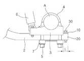
이러한 대형 트레일러 차량에 적용되는 종래 판스프링타입 서스펜션장치의 구성이 도 5에 예시되어 있는 바, 이를 참조하여 종래 판스프링타입 서스펜션장치의 구성을 개략적으로 살펴보면 아래와 같다.The structure of a conventional plate spring type suspension device applied to such a large trailer vehicle is illustrated in FIG. 5, and a structure of a conventional plate spring type suspension device will be briefly described below.
차체 하부에 행거(1)가 고정되어 있고, 상기 행거(1)에는 주행중 노면에서 가해지는 충격을 완충시키는 파라볼릭(parabolic) 형태의 판스프링아암(2)의 일단이 결합되어 있으며, 상기 판스프링아암(2)의 타단측에는 엑슬축(A, axle shaft)을 지지하는 엑슬시트(3)가 U-볼트(4)와 너트(5)의 체결을 통해 결합되어 있고, 상기 엑슬시트(3)에는 진동을 흡수하는 쇽업소버(6, shock absorber)가 결합되어 있다.A hanger (1) is fixed to a lower portion of a vehicle body. An end of a parabolic plate spring arm (2) for buffering impact applied from a road surface during traveling is coupled to the hanger (1) The
여기서, 상기 엑슬시트(3)의 결합구성을 보다 자세히 살펴보면, 판스프링아암(2)의 타단측 단부와 엑슬시트(3)의 측면 단부의 위치가 대략 일치되게 엑슬시트(3)가 판스프링아암(2)의 타단측 상부에 안착된 상태에서 엑슬시트(3)에 엑슬축(A)이 안착 지지된 후 엑슬축(A)을 감싸면서 U-볼트(4)가 엑슬시트(3)를 하향 관통하고, 엑슬시트(3) 하측으로 돌출된 U-볼트(4)에 지지플레이트(7)를 끼우고 너트(5)를 체결하는 구성으로 이루어게 된다.The
상기한 구성의 판스프링타입 서스펜션장치는 트레일러에 구비된 다수의 엑슬축(A)을 따라 엑슬축(A)의 양쪽에 독립적으로 복수개가 설치되게 된다.A plurality of leaf spring type suspension devices of the above-described configuration are independently provided on both sides of the axle axis A along a plurality of axle axes A provided on the trailer.
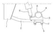
그런데, 상술한 구성의 종래 서스펜션장치는 엑슬시트(3)가 U-볼트(4)와 너트(5)의 체결력만으로 판스프링아암(2)에 결합되는 구조이므로 엑슬시트(3)와 판스프링아암(2)의 결합력이 취약하여 엑슬시트(3)가 체결위치로부터 밀리는 현상이 발생하는 문제점이 있다.Since the
즉, 엑슬시트(3)가 판스프링아암(2)의 타단측에 결합된 상태에서 주행 중 계속적으로 충격과 진동이 가해지게 되면 도 6에 일 예시된 것과 같이, 엑슬시트(3)가 판스프링아암(2)의 결합위치에서 판스프링아암(2)의 길이방향쪽으로 밀리는 현상이 발생되는 것이다.That is, when shock and vibration are continuously applied to the
이에, 상기한 밀림현상을 최대한 방지하기 위해서는 U-볼트(4)와 너트(5)가 규정된 적정 체결력으로 조립이 되어야만 하는데, 이렇게 적정 체결력으로 조립하기 위한 체결장비가 상당히 고가인 관계로 대부분의 업체에서는 체결의 중요성을 간과한 채 주로 작업자의 감각에 의존하여 U-볼트(4)와 너트(5)를 체결 조립하고 있는 것이 업계의 현실이며, 그에 따라 U-볼트(4)와 너트(5)가 적정한 체결력으로 조립되지 않음으로써 종래 판스프링타입 서스펜션장치에서는 상기한 엑슬시트(3)의 밀림현상이 자주 발생하고 있는 실정이다.In order to prevent the jamming phenomenon as much as possible, the
이러한 엑슬시트(3)의 밀림현상은 그 자체로서의 문제라기 보다는 엑슬축(A)과 바퀴의 정렬을 흐트러뜨리는 본질적인 문제점을 야기하게 되는 바, 즉 상기한 것처럼 액슬시트(3)에서 밀림현상이 발생하게 되면, 엑슬시트(3)에 지지된 엑슬축(A) 또한 변위가 되므로, 엑슬축(A)과 차량 바퀴의 정렬이 바로 이루어지지 않게 되는 것이며, 그에 따라 차량의 직진운전이 곤란해짐과 함께, 이로 인하여 대형사고의 위험성이 커지게 되고, 또한 타이어의 편마모를 유발함은 물론, 관련부품의 내구성을 급격하게 저하시키는 등 다양한 문제를 발생시키게 된다.The swing of the
도 7에는 이러한 엑슬시트(3)의 밀림현상에 따라 차량 바퀴의 정렬이 바로 이루어지지 않은 상태가 일 예시되어 있는 바, 정상적인 경우 1축부터 6축까지의 배열이 모두 평행한(축 간의 간격이 동일) 관계이어야 하지만, 밀림현상으로 인하여 5축 바퀴(이해의 편의를 위해 과도하게 도시됨.)의 정렬이 흐트러져 있음을 이해할 수 있다.7 shows a state in which the vehicle wheels are not aligned immediately following the swing of the
한편, 상기한 것처럼 엑슬시트(3)의 밀림현상에 따라 바퀴의 정렬이 비정상인 경우, 이를 정비하기 위해서는 트레일러 차량의 정비소 입고는 물론 작업시간이 최소 3일이상이 소요됨과 함께 하나의 축이 흐트러지더라도 모든 차축의 정렬을 재정비해야만 하므로 정비시간 및 비용이 과도하게 소요되는 문제점이 있으며, 무엇보다 군대의 트레일러 차량인 경우 전술훈련 등 작전에 투입되었을 때 이러한 문제점이 발생하면 전술훈련에 차질을 초래할 수도 있어 그 문제의 심각성이 매우 크다고 할 수 있다.If the alignment of the wheels is abnormal due to the swing of the
본 발명은 상술한 종래의 문제점을 해결하기 위하여 제안되는 것으로서, 본 발명의 목적은 간단한 구조개선을 통하여 엑슬시트의 밀림현상을 효율적으로 억제할 수 있으며, 이를 통하여 바퀴의 정렬상태가 흐트러지는 것을 방지할 수 있는 판스프링타입 서스펜션장치를 제공하는 것이다.SUMMARY OF THE INVENTION The present invention has been proposed in order to solve the problems of the prior art described above, and it is an object of the present invention to effectively prevent the swing of the axle seat through simple structure improvement, Which is capable of preventing a collision between the suspension and the suspension.
상기한 목적을 달성하기 위한 본 발명의 과제해결수단으로서,In order to achieve the above object, according to the present invention,
차체 하부에 고정된 행거와, 상기 행거에 일단이 결합된 파라볼릭 형태의 판스프링아암과, 엑슬축을 지지하면서 상기 판스프링아암의 타단측에 U-볼트에 의해 체결되는 엑슬시트와, 상기 엑슬시트와 차체 사이에 구비되는 쇽업소버를 포함하는 판스프링타입 서스펜션장치에 있어서, 상기 판스프링아암의 타단은 상기 엑슬시트의 측면에서 판스프링아암의 길이방향으로 일정길이 돌출되고, 상기 판스프링아암의 돌출부분 상면에는 논슬립 플레이트가 엑슬시트의 측면에 밀착된 상태로 안착되어 볼트 체결을 통해 결합되는 판스프링타입 서스펜션장치가 개시된다.A hanger fixed to a lower portion of the vehicle body; a parabolic-shaped plate spring arm having one end connected to the hanger; an axle seat which is supported by the U-bolt at the other end side of the plate spring arm while supporting the axle shaft; The other end of the leaf spring arm is protruded from the side surface of the axle seat by a predetermined length in the longitudinal direction of the leaf spring arm, and the protrusion of the leaf spring arm A plate spring type suspension device in which a non-slip plate is seated on a partial upper surface in a state of being closely attached to a side surface of an axle seat and is coupled through bolt tightening.
여기서, 상기 논슬립 플레이트는 상기 엑슬시트의 측면에 일체로 형성될 수 있다.Here, the non-slip plate may be integrally formed on the side surface of the axle sheet.
본 발명에 따른 판스프링타입 서스펜션장치에 의하면,According to the leaf spring type suspension device of the present invention,
엑슬시트의 밀림현상을 효율적으로 방지하여 차량 바퀴의 정렬상태가 흐트러지는 것을 예방할 수 있으며, 이를 통해 대형사고의 위험성과 관련부품의 손상 문제 및 수리에 따른 부담 등 종래 서스펜션장치의 문제점을 일거에 해소할 수 있는 장점이 있다.It is possible to prevent the alignment of the vehicle wheels from being disturbed by effectively preventing the axle seat from being jammed, thereby eliminating the problems of conventional suspension devices such as the risk of major accidents, There is an advantage to be able to do.
또한, 복잡하거나 큰 구조의 변경이 아니라 비교적 간단한 구조개선을 통해 밀림현상을 방지하므로 제조비용의 인상을 최소화할 수 있어 효율성이 좋은 장점도 있다.Also, it is possible to minimize the increase of the manufacturing cost by preventing the jamming phenomenon through relatively simple structure improvement rather than a complicated or large structure change, which is also advantageous in efficiency.
아울러, 상기한 바와 같이 구체적으로 명시한 효과 이외에 본 발명의 특징적인 구성으로부터 용이하게 도출되고 기대될 수 있는 특유한 효과 또한 본 발명의 효과에 포함될 수 있음을 첨언한다.It is to be noted that, in addition to the effect specifically described above, a specific effect that can be easily derived and expected from the characteristic configuration of the present invention can also be included in the effect of the present invention.
도 1은 본 발명의 일 실시예에 따른 판스프링타입 서스펜션장치의 구성을 나타내는 도면이고,
도 2는 논슬립 플레이트가 결합되기 전 상태의 판스프링타입 서스펜션장치를 나타내는 도면이며,
도 3은 논슬립 플레이트가 결합된 상태의 판스프링타입 서스펜션장치를 나타내는 도면이고,
도 4는 논슬립 플레이트가 일체로 형성된 엑슬시트를 나타내는 도면이며,
도 5는 종래 판스프링타입 서스펜션장치의 구성을 일 예시한 도면이고,
도 6은 종래 판스프링 서스펜션장치에서 엑슬시트의 밀림현상이 발생된 상태를 일 예시한 도면이며,
도 7은 엑슬시트의 밀림현상에 따라 차축의 정렬이 흐트러진 상태를 일 예시한 도면이다.1 is a view showing a configuration of a leaf spring type suspension device according to an embodiment of the present invention,
2 is a view showing a plate spring type suspension device before the non-slip plate is engaged,
3 is a view showing a leaf spring type suspension device with a non-slip plate coupled thereto,
4 is a view showing an axle sheet in which a non-slip plate is integrally formed,
5 is a view illustrating a configuration of a conventional plate spring type suspension device,
6 is a view illustrating a state in which a swinging phenomenon of an axle seat occurs in a conventional leaf spring suspension device,
FIG. 7 is a diagram illustrating a state in which the axle alignment is disturbed according to the swing of the axle seat.
이하에서, 첨부된 도면들을 참조하여 본 발명에 따른 판스프링타입 서스펜션장치에 대한 바람직한 실시예를 상세하게 설명하기로 한다.Hereinafter, preferred embodiments of a leaf spring type suspension device according to the present invention will be described in detail with reference to the accompanying drawings.
본 실시예는 당업계에서 평균적인 지식을 가진 자에게 본 발명을 보다 완전하게 설명하기 위해서 제공되어지는 것으로서, 첨부된 도면에서의 요소의 형상, 크기, 요소간의 간격 등은 보다 명확한 설명을 강조하기 위해서 축소되거나 과장되어 표현될 수 있음을 유의하여야 한다.It is to be understood that both the foregoing general description and the following detailed description are exemplary and explanatory and are intended to provide further explanation of the invention to those skilled in the art, It should be noted that the present invention can be reduced or exaggerated for the sake of simplicity.
아울러, 실시예를 설명하는데 있어서 원칙적으로 관련된 공지의 기능이나 공지의 구성과 같이 이미 당해 기술분야의 통상의 기술자에게 자명한 사항으로서 본 발명의 기술적 특징을 불필요하게 흐릴 수 있다고 판단되는 경우에는 그 상세한 설명을 생략하기로 한다.
In addition, when describing the embodiments, in the case where it is judged that technical characteristics of the present invention may be unnecessarily blurred as a matter known to those skilled in the art, such as known functions and configurations well known in the art, Description thereof will be omitted.
도 1 내지 도 4는 본 발명의 일 실시예에 따른 판스프링타입 서스펜션장치을 나타내는 도면들로서, 상기 도면들을 참조하면, 본 발명의 일 실시예에 따른 판스프링타입 서스펜션장치(이하, “서스펜션장치”로 약칭함.)는 종래의 서스펜션장치와 동일한 행거(1)와, 판스프링아암(2)과, 엑슬시트(3)와, U-볼트(4) 및 너트(5)와, 쇽업소버(6)와 함께, 엑슬시트(3)의 밀림방지를 위한 논슬립 플레이트(10)를 포함하여 구성되는 바, 종래와 동일한 구성요소에 대해서는 간략하게 설명함과 함께 종래와 동일한 구성요소에 대해서는 동일한 명칭과 부호를 붙여 설명하기로 한다.1 to 4 are views showing a leaf spring type suspension device according to an embodiment of the present invention. Referring to the drawings, a leaf spring type suspension device according to an embodiment of the present invention (hereinafter referred to as " suspension device " A
상기 판스프링아암(2)은 일단이 행거(1)에 결합되며, 상기 판스프링아암(2)의 타단측에는 상기 엑슬시트(3)가 U-볼트(4) 및 너트(5)의 체결을 통해 결합되고, 상기 쇽업소버(6)가 엑슬시트(3)와 차체 사이에 결합되며, 상기 엑슬시트(3)에 엑슬축(A)이 지지됨은 종래와 동일하다.One end of the
여기서, 본 발명의 실시예는 상기와 같이 U-볼트(4) 및 너트(5)의 체결에 의해 판스프링아암(2)의 타단측에 결합되는 엑슬시트(3)의 밀림현상 방지를 위해 상기 논슬립 플레이트(10)를 포함하게 된다.Here, in order to prevent the
또한, 상기 판스프링아암(2)은 기존의 판스프링아암보다 일정길이(L) 길게 형성되며, 그에 따라 상기 판스프링아암(2)의 타단에는 상기 엑슬시트(3)의 측면에서 판스프링아암(2)의 길이방향으로 일정길이(L) 돌출된 돌출부분(20)이 형성된다.The
여기서, 상기 돌출부분(20)의 길이(L)는 상기 논슬립 플레이트(10)의 폭에 대응될 수 있다.Here, the length L of the projecting
그리고, 상기 논슬립 플레이트(10)와 상기 판스프링아암(2)의 돌출부분(20)에는 체결볼트(30)가 관통 체결될 수 있도록 각각 볼트홀(31)이 형성될 수 있다.
이에 따라, 상기 논슬립 플레이트(10)가 상기 엑슬시트(3)의 측면에 밀착되면서 상기 판스프링아암(2)의 돌출부분(20) 상면에 안착되고, 이렇게 안착된 논슬립 플레이트(10)와 상기 판스프링아암(2)의 돌출부분(20)을 상기 체결볼트(30)로 체결함으로써 논슬립 플레이트(10)와 판스프링아암(2) 상호간의 결합이 이루어질 수 있다.The
이렇게 논슬립 플레이트(10)가 판스프링아암(2)과 결합되면, 논슬립 플레이트(10)가 엑슬시트(3)와 밀착된 상태에서 고정되므로 엑슬시트(3)가 판스프링아암(2)의 길이방향으로 밀려날 때 논슬립 플레이트(10)에 걸리면서 밀림 변위가 억제되며, 그에 따라 U-볼트(4)가 적정한 체결력으로 조립되지 못한 경우에도 엑슬시트(3)의 밀림현상을 효율적으로 방지할 수 있게 된다.When the
상기와 같이 판스프링아암(2)의 돌출부분(20)과 결합되어 엑슬시트(3)의 밀림을 억제하는 논슬립 플레이트(10)는 도 2 내지 도 3에 도시된 것처럼 엑슬시트(3)와는 분리되는 별도의 구성부분으로 형성될 수도 있고, 또는 도 4에 도시된 것처럼 엑슬시트(3)의 측면 단부에 일체로 형성될 수도 있다.The
상기한 구성에 따른 본 발명의 서스펜션장치를 설치함에 있어서는, 종래와 동일하게, 먼저 U-볼트(4)와 너트(5) 체결을 통해 엑슬시트(3)를 판스프링아암(2)의 타단측 결합위치에 결합시켜준다.When mounting the suspension device of the present invention according to the above-described configuration, the
이렇게 결합시키면 판스프링아암(2)의 끝단부가 엑슬시트(3)의 측면 단부에서 돌출되는 바, 논슬립 플레이트(10)가 엑슬시트(3)에 일체로 형성된 구성인 경우에는, 상기 판스프링아암(2)의 돌출부분(20) 상면에 논슬립 플레이트(10)가 바로 안착된 상태가 되므로 그 상태에서 바로 체결볼트(30)를 체결하여 논슬립 플레이트(10)와 판스프링아암(2)의 돌출부분(20)을 상호 결합시키면 된다.In this case, when the
또한, 논슬립 플레이트(10)가 엑슬시트(3)와는 독립된 분리형인 구성의 경우에는, 상기 돌출부분(20) 상면에 논슬립 플레이트(10)가 엑슬시트(3)의 측면에 밀착되도록 별도로 안착시킨 후에 체결볼트(30)를 체결함으로써 논슬립 플레이트(10)와 판스프링아암(2)의 돌출부분(20)을 상호 결합시키면 설치가 간단하게 완료된다.When the
이상에서 설명한 본 발명의 서스펜션장치는 U-볼트(4)와 너트(5)의 체결력 외에 논슬립 플레이트(10)에 의해 엑슬시트(3)의 위치가 구속되므로 엑슬시트(3)의 밀림 변위를 효율적으로 억제할 수 있으며, 이를 통해 차량 바퀴의 정렬상태가 흐트러지는 것을 방지할 수 있음을 알 수 있다.Since the position of the
또한, 종래 서스펜션장치의 구조를 크게 변경하게 되면 비록 밀림현상 방지라는 기술적 목적은 달성한다 하더라도, 구조변경에 따른 제조비용의 지나친 증가로 인하여 그러한 기술개발의 전체적인 효율성이 떨어질 수 밖에 없는 문제점이 있게 되는데, 본 발명에 따른 서스펜션장치의 경우, 가장 고가의 구성부분인 판스프링아암의 구조나 형상의 변경없이 단지 규격보다 길이만 일부 증가될 뿐이므로 종래와 동일한 인발성형의 단일 제조공정을 통해 제조가 가능함과 함께, 다른 구성의 변경없이 논슬립 플레이트만이 추가된 간단한 구조개선이므로, 밀림현상 방지라는 기술적 효과를 달성함과 동시에 구조개선에 따른 서스펜션장치의 제조비용 인상은 최소화할 수 있어 전체적인 기술개발의 효율성이 매우 높음을 알 수 있다.Further, if the structure of the conventional suspension device is largely changed, even if the technical purpose of preventing the skid phenomenon is achieved, there is a problem that the overall efficiency of the technology development is deteriorated due to an excessive increase in the manufacturing cost due to the structural change , The suspension device according to the present invention can be manufactured through a single manufacturing process of the same drawing die as the conventional one because the length of the plate spring arm, which is the most expensive component, And a simple structure improvement in which only the non-slip plate is added without changing the other constitution, the technical effect of prevention of the skidding phenomenon can be achieved, and the manufacturing cost increase of the suspension device due to the structure improvement can be minimized, Is very high.
이상으로 본 발명의 바람직한 실시예를 상세하게 설명하였는데, 본 발명의 기술적 범위는 상술한 실시예 및 도면들에 기재된 내용으로 한정되는 것은 아니며, 해당 기술분야의 통상의 지식을 가진 자에 의해 수정 또는 변경된 등가의 구성은 본 발명의 기술적 사상의 범위를 벗어나지 않는 것이라 할 것이다.While the present invention has been particularly shown and described with reference to exemplary embodiments thereof, it is to be understood that the technical scope of the invention is not limited to the disclosed exemplary embodiments and drawings, It will be understood that the modified equivalent structure is not limited to the scope of the present invention.
첨부된 도면들의 주요부위에 대한 부호를 설명하면 다음과 같다.
1: 행거2: 판스프링아암
3: 엑슬시트4: U-볼트
5: 너트6: 쇽업소버
10: 논슬립 플레이트20: 돌출부분
30: 체결볼트The main parts of the accompanying drawings are as follows.
1: Hanger 2: Plate spring arm
3: axle seat 4: U-bolt
5: Nut 6: Shock absorber
10: non-slip plate 20: protruding portion
30: fastening bolt
Claims (2)
Translated fromKorean상기 판스프링아암(2)의 타단은 상기 엑슬시트(3)의 측면에서 판스프링아암(2)의 길이방향으로 일정 길이(L) 돌출되고, 상기 판스프링아암(2)의 돌출부분 (20) 상면에는 논슬립 플레이트(10)가 엑슬시트(3)의 측면에 밀착된 상태로 안착되어 체결볼트(30)의 체결을 통해 결합되는 것을 특징으로 하는 판스프링타입 서스펜션장치.A hanger 1 fixed to the lower part of the vehicle body; a plate spring arm 2 in the form of a parabolic shape having one end connected to the hanger 1; An axle seat 3 which is fastened by a U-bolt 4 and a nut 5 on a short side and a shock absorber 6 which is provided between the axle seat 3 and the vehicle body As a result,
The other end of the plate spring arm 2 protrudes a predetermined length L in the longitudinal direction of the plate spring arm 2 from the side surface of the axle seat 3 and the protruding portion 20 of the plate spring arm 2, Wherein the non-slip plate (10) is seated on the upper surface of the axle seat (3) in close contact with the side surface of the axle seat (3) and is fastened by tightening the fastening bolt (30).
상기 논슬립 플레이트(10)는 상기 엑슬시트(3)의 측면에 일체로 형성되는 것을 특징으로 하는 판스프링타입 서스펜션장치.The method according to claim 1,
Wherein the non-slip plate (10) is integrally formed on a side surface of the axle seat (3).
Priority Applications (1)
| Application Number | Priority Date | Filing Date | Title |
|---|---|---|---|
| KR1020140035844AKR20150113250A (en) | 2014-03-27 | 2014-03-27 | Leaf spring Suspension |
Applications Claiming Priority (1)
| Application Number | Priority Date | Filing Date | Title |
|---|---|---|---|
| KR1020140035844AKR20150113250A (en) | 2014-03-27 | 2014-03-27 | Leaf spring Suspension |
Related Child Applications (1)
| Application Number | Title | Priority Date | Filing Date |
|---|---|---|---|
| KR2020150007186UDivisionKR20150004507U (en) | 2015-11-05 | 2015-11-05 | Leaf spring Suspension |
Publications (1)
| Publication Number | Publication Date |
|---|---|
| KR20150113250Atrue KR20150113250A (en) | 2015-10-08 |
Family
ID=54346219
Family Applications (1)
| Application Number | Title | Priority Date | Filing Date |
|---|---|---|---|
| KR1020140035844AWithdrawnKR20150113250A (en) | 2014-03-27 | 2014-03-27 | Leaf spring Suspension |
Country Status (1)
| Country | Link |
|---|---|
| KR (1) | KR20150113250A (en) |
Cited By (4)
| Publication number | Priority date | Publication date | Assignee | Title |
|---|---|---|---|---|
| CN112347562A (en)* | 2020-11-12 | 2021-02-09 | 山东太岳汽车弹簧制造有限公司 | Design method of parabolic guide arm trailer air suspension system |
| KR102323559B1 (en)* | 2020-08-10 | 2021-11-09 | (주)카츠코리아 | Suspension for boat trailer with shock absorbing structure |
| DE202022103702U1 (en) | 2021-07-06 | 2022-09-27 | Hyundai Mobis Co., Ltd. | suspension for a vehicle |
| DE202022103705U1 (en) | 2021-07-07 | 2022-09-28 | Hyundai Mobis Co., Ltd. | suspension for a vehicle |
- 2014
- 2014-03-27KRKR1020140035844Apatent/KR20150113250A/ennot_activeWithdrawn
Cited By (7)
| Publication number | Priority date | Publication date | Assignee | Title |
|---|---|---|---|---|
| KR102323559B1 (en)* | 2020-08-10 | 2021-11-09 | (주)카츠코리아 | Suspension for boat trailer with shock absorbing structure |
| CN112347562A (en)* | 2020-11-12 | 2021-02-09 | 山东太岳汽车弹簧制造有限公司 | Design method of parabolic guide arm trailer air suspension system |
| CN112347562B (en)* | 2020-11-12 | 2021-10-08 | 山东太岳汽车弹簧制造有限公司 | Design method of parabolic guide arm trailer air suspension system |
| DE202022103702U1 (en) | 2021-07-06 | 2022-09-27 | Hyundai Mobis Co., Ltd. | suspension for a vehicle |
| US12179532B2 (en) | 2021-07-06 | 2024-12-31 | Hyundai Mobis Co., Ltd. | Suspension for vehicle |
| DE202022103705U1 (en) | 2021-07-07 | 2022-09-28 | Hyundai Mobis Co., Ltd. | suspension for a vehicle |
| US11660923B2 (en) | 2021-07-07 | 2023-05-30 | Hyundai Mobis Co., Ltd. | Suspension for vehicle |
Similar Documents
| Publication | Publication Date | Title |
|---|---|---|
| CN105377594A (en) | Vehicle suspension and leaf spring therefore | |
| GB2419653A (en) | A stabilizer bar and bushing assembly | |
| US8376380B2 (en) | Traction device | |
| KR20150113250A (en) | Leaf spring Suspension | |
| CN201694022U (en) | An outer limit disconnecting type balance suspension device | |
| US7055895B1 (en) | Protective plate assembly for land vehicle drive line and wheel differential | |
| US8801018B2 (en) | Wind-up control link | |
| KR101639787B1 (en) | air-spring installation structure for vehicle | |
| CN204210415U (en) | A kind of reverse collision prevention shock absorption device | |
| KR100316887B1 (en) | Suspension system for vehicles | |
| CN202029661U (en) | Bumper-mounting structure for automotive suspension systems | |
| KR20150004507U (en) | Leaf spring Suspension | |
| KR102253495B1 (en) | Coil Spring Device for Automobile Suspension | |
| KR20140044654A (en) | Structure for mounting suspension apparatus on vehicle body | |
| KR100853921B1 (en) | Automotive Coupled Torsion Beam Axle | |
| CN102729749A (en) | Vehicle axle device | |
| KR102417402B1 (en) | Strut assembly for vehicle | |
| EP2992239A1 (en) | Spring device and spring suspension | |
| KR102238053B1 (en) | Multi link rear suspension for vehicle | |
| KR102263724B1 (en) | Suspention Of Vehicle | |
| KR200300862Y1 (en) | Asistance buffer equipment have a suspension system of trailer | |
| US7992277B2 (en) | Suspension damper removal tool | |
| KR20190002070A (en) | Rear damper for cargo vehicle | |
| KR20080021408A (en) | Car suspension | |
| KR20130023557A (en) | Method for assembling trailing arm of vehicle |
Legal Events
| Date | Code | Title | Description |
|---|---|---|---|
| A201 | Request for examination | ||
| PA0109 | Patent application | Patent event code:PA01091R01D Comment text:Patent Application Patent event date:20140327 | |
| PA0201 | Request for examination | ||
| E902 | Notification of reason for refusal | ||
| PE0902 | Notice of grounds for rejection | Comment text:Notification of reason for refusal Patent event date:20150223 Patent event code:PE09021S01D | |
| E902 | Notification of reason for refusal | ||
| PE0902 | Notice of grounds for rejection | Comment text:Notification of reason for refusal Patent event date:20150908 Patent event code:PE09021S01D | |
| PG1501 | Laying open of application | ||
| PC1205 | Withdrawal of application forming a basis of a converted application | ||
| WICV | Withdrawal of application forming a basis of a converted application |