KR20150112484A - Heat sink structure and light emitting device including the same - Google Patents
Heat sink structure and light emitting device including the sameDownload PDFInfo
- Publication number
- KR20150112484A KR20150112484AKR1020140036769AKR20140036769AKR20150112484AKR 20150112484 AKR20150112484 AKR 20150112484AKR 1020140036769 AKR1020140036769 AKR 1020140036769AKR 20140036769 AKR20140036769 AKR 20140036769AKR 20150112484 AKR20150112484 AKR 20150112484A
- Authority
- KR
- South Korea
- Prior art keywords
- refrigerant
- heat dissipating
- heat
- light emitting
- region
- Prior art date
- Legal status (The legal status is an assumption and is not a legal conclusion. Google has not performed a legal analysis and makes no representation as to the accuracy of the status listed.)
- Withdrawn
Links
- 239000003507refrigerantSubstances0.000claimsabstractdescription73
- 238000001704evaporationMethods0.000claimsabstractdescription40
- 230000008020evaporationEffects0.000claimsabstractdescription38
- 239000000463materialSubstances0.000claimsabstractdescription27
- 230000002209hydrophobic effectEffects0.000claimsabstractdescription15
- 238000009833condensationMethods0.000claimsdescription26
- 230000005494condensationEffects0.000claimsdescription26
- 230000017525heat dissipationEffects0.000claimsdescription12
- 230000005855radiationEffects0.000claimsdescription11
- OKTJSMMVPCPJKN-UHFFFAOYSA-NCarbonChemical compound[C]OKTJSMMVPCPJKN-UHFFFAOYSA-N0.000claimsdescription6
- 229910021389grapheneInorganic materials0.000claimsdescription6
- 239000011248coating agentSubstances0.000claimsdescription4
- 238000000576coating methodMethods0.000claimsdescription4
- 238000007598dipping methodMethods0.000claimsdescription3
- 238000000034methodMethods0.000claims13
- 230000005484gravityEffects0.000description8
- 238000005286illuminationMethods0.000description4
- 239000012530fluidSubstances0.000description3
- 238000012423maintenanceMethods0.000description3
- 230000000694effectsEffects0.000description2
- 125000004432carbon atomChemical groupC*0.000description1
- 230000006866deteriorationEffects0.000description1
- 230000020169heat generationEffects0.000description1
- 238000004519manufacturing processMethods0.000description1
- 238000012986modificationMethods0.000description1
- 230000004048modificationEffects0.000description1
- 238000004904shorteningMethods0.000description1
- 239000000126substanceSubstances0.000description1
Images


Classifications
- F—MECHANICAL ENGINEERING; LIGHTING; HEATING; WEAPONS; BLASTING
- F21—LIGHTING
- F21V—FUNCTIONAL FEATURES OR DETAILS OF LIGHTING DEVICES OR SYSTEMS THEREOF; STRUCTURAL COMBINATIONS OF LIGHTING DEVICES WITH OTHER ARTICLES, NOT OTHERWISE PROVIDED FOR
- F21V29/00—Protecting lighting devices from thermal damage; Cooling or heating arrangements specially adapted for lighting devices or systems
- F21V29/50—Cooling arrangements
- F21V29/51—Cooling arrangements using condensation or evaporation of a fluid, e.g. heat pipes
- F—MECHANICAL ENGINEERING; LIGHTING; HEATING; WEAPONS; BLASTING
- F21—LIGHTING
- F21Y—INDEXING SCHEME ASSOCIATED WITH SUBCLASSES F21K, F21L, F21S and F21V, RELATING TO THE FORM OR THE KIND OF THE LIGHT SOURCES OR OF THE COLOUR OF THE LIGHT EMITTED
- F21Y2115/00—Light-generating elements of semiconductor light sources
- F21Y2115/10—Light-emitting diodes [LED]
Landscapes
- Engineering & Computer Science (AREA)
- General Engineering & Computer Science (AREA)
- Cooling Or The Like Of Semiconductors Or Solid State Devices (AREA)
Abstract
Translated fromKoreanDescription
Translated fromKorean본원은 방열 구조체 및 이를 포함하는 발광 장치에 관한 것이다.The present invention relates to a heat dissipating structure and a light emitting device including the same.
일반적으로 조명 장치는 빛을 발산하는 장치로서, 근래에는, 조명 장치의 수명을 향상시킬 수 있고 에너지효율을 크게 향상시킬 수 있는 발광다이오드(LED)를 광원으로 채택한 조명 장치가 이용되고 있다.2. Description of the Related Art [0002] In general, an illumination device is a device that emits light. Recently, a lighting device has been used which employs a light emitting diode (LED) as a light source, which can improve the lifetime of the illumination device and greatly improve energy efficiency.
그런데, LED는 전압을 가하면 열에너지와 빛에너지가 동시에 방출되는 특성이 있어서, 조명장치의 구동시 LED에서 발생되는 열로 인해 빛 에너지가 감소되고 결국 LED의 휘도가 저하되는 문제가 있으며, LED 및 그 외 조명장치에 포함되는 부품이 LED의 발열로 인해 손상되기도 하여 조명장치의 수명이 단축되는 문제가 있다.However, when a voltage is applied to the LED, heat energy and light energy are simultaneously emitted. Therefore, there is a problem that the light energy is reduced due to the heat generated from the LED when the lighting device is driven, There is a problem that the parts included in the lighting apparatus are damaged due to heat generation of the LED, shortening the service life of the lighting apparatus.
이에 따라, 히트 파이프를 이용해 열을 순환시킴으로써 방열 효율을 향상시킨 조명 장치가 대한민국 공개특허공보 제10-2010-0132213호에 개시된 바 있다.Accordingly, a lighting apparatus improved in heat radiation efficiency by circulating heat using a heat pipe has been disclosed in Korean Patent Laid-Open Publication No. 10-2010-0132213.
그런데 개시된 조명 장치가 포함하는 히트 파이프는, 작동유체를 모세관 현상을 통해 이동시키는 윅(wick)을 포함하는바, 모세관 현상의 구현을 위해 히트 파이프의 구성이 복잡해지고, 모세관 현상의 구현을 위해 윅이 높은 친수성을 갖는 재질로 이루어져 작동유체가 이동되기는 하지만, 그 이동 속도가 느려 방열 효율 면에서 한계가 있다는 문제점이 있었다.The heat pipe included in the disclosed lighting device includes a wick for moving the working fluid through the capillary phenomenon. In order to realize the capillary phenomenon, the heat pipe is complicated in configuration, Is made of a material having a high hydrophilicity to move the working fluid. However, the moving speed of the working fluid is low, which limits the heat dissipation efficiency.
본원은 전술한 종래 기술의 문제점을 해결하기 위한 것으로서, 단순한 구조로 방열 효율을 극대화시킨 방열 구조체 및 발광 소자를 제공하는 것을 목적으로 한다.It is an object of the present invention to provide a heat dissipating structure and a light emitting device having a simple structure and maximizing heat dissipation efficiency.
상기한 기술적 과제를 달성하기 위한 기술적 수단으로서, 본원의 제1 측면에 따른 방열 구조체는, 소자 설치부; 및 상기 소자 설치부의 상부에 구비되고 냉매가 수용되는 냉매 수용영역, 상기 냉매 중 기화된 냉매가 상승 이동하는 증발영역 및 상승 이동한 상기 기화된 냉매가 응축되는 응축영역이 수직 방향을 따라 순차적으로 형성되는 방열 몸체를 포함하되, 상기 방열 몸체는 소수성 물질로 코팅될 수 있다.According to an aspect of the present invention, there is provided a heat dissipating structure comprising: a device mounting portion; And a condensing region provided on the upper portion of the element mounting portion and in which the refrigerant is received, an evaporation region in which the vaporized refrigerant moves upward and a condensed region in which the vaporized refrigerant is moved upward, are sequentially formed along the vertical direction The heat dissipating body may be coated with a hydrophobic material.
또한, 본원의 제2 측면에 따른 발광 장치는, 본원의 제1 측면에 따른 방열 구조체; 및 상기 소자 설치부에 설치되는 하나 이상의 발광 소자를 포함할 수 있다.Further, the light emitting device according to the second aspect of the present invention comprises: the heat dissipating structure according to the first aspect of the present invention; And one or more light emitting devices provided in the device mounting portion.
전술한 본원의 과제 해결 수단에 의하면, 냉매 수용영역, 증발영역 및 응축영역이 수직 방향을 따라 순차적으로 형성됨으로써, 냉매 수용영역에서 기화되어 응축영역으로 향한 냉매가 열 에너지를 방출하여 응축된 후, 중력에 의해 냉매 수용영역으로 회귀할 수 있어, 중력을 이용한 냉매의 순환 방식을 갖는 간명한 구조의 방열 구조체가 구현될 수 있다.According to the above-mentioned problem solving means of the present invention, since the refrigerant receiving area, the evaporation area and the condensing area are sequentially formed along the vertical direction, the refrigerant vaporized in the refrigerant receiving area and directed toward the condensing area radiates heat and condenses, It is possible to return to the refrigerant receiving area by gravity, and a heat radiating structure having a simple structure having a refrigerant circulation system using gravity can be realized.
또한, 이러한 방열 구조체를 포함하는 발광 장치에 의하면, 발광 장치의 방열 효율이 극대화될 수 있어, 열에 의한 광 출력 효율 감소 및 휘도 저하를 막아 발광 장치의 신뢰성이 향상될 수 있으며, 부품의 손상을 막아 유지보수 비용을 절감하면서 발광 장치의 수명 또한 향상될 수 있다.Further, according to the light emitting device including such a heat radiation structure, the heat radiation efficiency of the light emitting device can be maximized, the light output efficiency due to heat and efficiency of the light emitting device can be improved by preventing the brightness lowering, The lifetime of the light emitting device can be improved while reducing the maintenance cost.
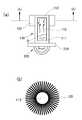
도 1의 (a)는 본원의 일 실시예의 제1 구현예에 따른 방열 구조체를 측면에서 바라본 개략적인 단면도이다.
도 1의 (b)는 본원의 일 실시예의 제1 구현예에 따른 방열 구조체를 도 1의 (b)-(b)선을 따라 절개한 개략적인 단면도이다.
도 2의 (a)는 본원의 일 실시예의 제2 구현예에 따른 방열 구조체의 개략적인 사시도이다.
도 2의 (b)는 본원의 일 실시예의 제2 구현예에 따른 방열 구조체를 도 2의 (a)의 (b)-(b)선을 따라 절개한 개략적인 단면도이다.
도 3은 증발관이 나선형으로 연장 구비된 본원의 일 실시예의 제2 구현예에 따른 방열 구조체를 측면에서 바라본 개략적인 단면도이다.
도 4는 응축영역의 상면 및 하면이 통로영역을 향해 비스듬하게 형성된 본원의 일 실시예의 제2 구현예에 따른 방열 구조체를 측면에서 바라본 개략적인 단면도이다.FIG. 1 (a) is a schematic cross-sectional view of a heat radiating structure according to a first embodiment of the present invention, as viewed from the side.
FIG. 1 (b) is a schematic cross-sectional view of the heat-radiating structure according to the first embodiment of the present invention cut along the line (b) - (b) of FIG.
2 (a) is a schematic perspective view of a heat radiation structure according to a second embodiment of the present invention.
2 (b) is a schematic cross-sectional view of the heat dissipating structure according to the second embodiment of the present invention cut along the line (b) - (b) of FIG. 2 (a).
3 is a schematic cross-sectional side view of a heat radiation structure according to a second embodiment of the present invention, in which the evaporation tube extends spirally.
4 is a schematic cross-sectional side view of a heat radiation structure according to a second embodiment of the present invention, in which the upper and lower surfaces of the condensation region are formed obliquely toward the passage region.
아래에서는 첨부한 도면을 참조하여 본원이 속하는 기술 분야에서 통상의 지식을 가진 자가 용이하게 실시할 수 있도록 본원의 실시예를 상세히 설명한다. 그러나 본원은 여러 가지 상이한 형태로 구현될 수 있으며 여기에서 설명하는 실시예에 한정되지 않는다. 그리고 도면에서 본원을 명확하게 설명하기 위해서 설명과 관계없는 부분은 생략하였으며, 명세서 전체를 통하여 유사한 부분에 대해서는 유사한 도면 부호를 붙였다.Hereinafter, embodiments of the present invention will be described in detail with reference to the accompanying drawings so that those skilled in the art can easily carry out the present invention. It should be understood, however, that the present invention may be embodied in many different forms and should not be construed as limited to the embodiments set forth herein. In the drawings, the same reference numbers are used throughout the specification to refer to the same or like parts.
본원 명세서 전체에서, 어떤 부분이 다른 부분과 "연결"되어 있다고 할 때, 이는 "직접적으로 연결"되어 있는 경우뿐 아니라, 그 중간에 다른 소자를 사이에 두고 "전기적으로 연결"되어 있는 경우도 포함한다.Throughout this specification, when a part is referred to as being "connected" to another part, it is not limited to a case where it is "directly connected" but also includes the case where it is "electrically connected" do.
본원 명세서 전체에서, 어떤 부재가 다른 부재 “상에” 위치하고 있다고 할 때, 이는 어떤 부재가 다른 부재에 접해 있는 경우뿐 아니라 두 부재 사이에 또 다른 부재가 존재하는 경우도 포함한다.Throughout this specification, when a member is " on " another member, it includes not only when the member is in contact with the other member, but also when there is another member between the two members.
본원 명세서 전체에서, 어떤 부분이 어떤 구성요소를 "포함" 한다고 할 때, 이는 특별히 반대되는 기재가 없는 한 다른 구성요소를 제외하는 것이 아니라 다른 구성 요소를 더 포함할 수 있는 것을 의미한다. 본원 명세서 전체에서 사용되는 정도의 용어 "약", "실질적으로" 등은 언급된 의미에 고유한 제조 및 물질 허용오차가 제시될 때 그 수치에서 또는 그 수치에 근접한 의미로 사용되고, 본원의 이해를 돕기 위해 정확하거나 절대적인 수치가 언급된 개시 내용을 비양심적인 침해자가 부당하게 이용하는 것을 방지하기 위해 사용된다. 본원 명세서 전체에서 사용되는 정도의 용어 "~(하는) 단계" 또는 "~의 단계"는 "~ 를 위한 단계"를 의미하지 않는다.Throughout this specification, when an element is referred to as "including " an element, it is understood that the element may include other elements as well, without departing from the other elements unless specifically stated otherwise. The terms "about "," substantially ", etc. used to the extent that they are used throughout the specification are intended to be taken to mean the approximation of the manufacturing and material tolerances inherent in the stated sense, Accurate or absolute numbers are used to help prevent unauthorized exploitation by unauthorized intruders of the referenced disclosure. The word " step (or step) "or" step "used to the extent that it is used throughout the specification does not mean" step for.
참고로, 본원의 실시예에 관한 설명 중 방향이나 위치와 관련된 용어(상부, 상면, 하부, 하면 등)는 도면에 나타나 있는 각 구성의 배치 상태를 기준으로 설정한 것이다. 예를 들어 도 1, 도 2의 (b), 도 3 및 도 4를 보았을 때 전반적으로 12시 방향을 향하는 부분이 상부, 전반적으로 12시 방향을 향하는 면이 상면, 전반적으로 6시 방향을 향하는 부분이 하부, 전반적으로 6시 방향을 향하는 면이 하면 등이 될 수 있다.For the sake of convenience, the term (top, top, bottom, bottom, and the like) related to the direction or position in the description of the embodiments of the present application is set based on the arrangement state of each structure shown in the drawings. For example, referring to FIGS. 1, 2 (b), 3 and 4, when the portion facing the 12 o'clock direction is the upper portion, the surface facing the 12 o'clock direction as a whole is the upper surface, The bottom portion, the side facing the 6 o'clock direction as a whole, and the like.
이하에서는, 본원의 일 실시예에 따른 방열 구조체(이하 '본 방열 구조체'라 함)에 대해 설명한다.Hereinafter, a heat radiation structure according to an embodiment of the present invention (hereinafter referred to as " main heat radiation structure ") will be described.
도 1의 (a)는 본원의 일 실시예의 제1 구현예에 따른 방열 구조체를 측면에서 바라본 개략적인 단면도이고, 도 1의 (b)는 본원의 일 실시예의 제1 구현예에 따른 방열 구조체를 도 1의 (b)-(b)선을 따라 절개한 개략적인 단면도이다.1 (a) is a schematic cross-sectional view of a heat radiating structure according to a first embodiment of the present invention as viewed from the side, and FIG. 1 (b) is a cross-sectional view of a heat radiating structure according to a first embodiment of the present invention Sectional view taken along line (b) - (b) of Fig. 1.
도 1을 참조하면, 본 방열 구조체는, 소자 설치부(210) 및 소자 설치부(210)의 상부에 구비되고 냉매(0)가 수용되는 냉매 수용영역(111), 냉매(0) 중 기화된 냉매(0)가 상승 이동하는 증발영역(113) 및 기화된 냉매(0)가 응축되는 응축영역(112)을 포함하는 방열 몸체(110)를 포함한다.1, the present heat-dissipating structure includes a
냉매 수용영역(111)은 냉매(0)가 외부 열원에 의해 가열되는 영역으로서, 냉매(0)가 열 에너지를 받아 증발할 수 있다.The
또한, 증발영역(113)은 기화된 냉매(0)의 이동 통로가 될 수 있다. 기화된 냉매(0)를 포함하는 고온의 기체는 증발영역(113)을 통해 이동하면서 계속적으로 방열하게 되며, 이에 따라 기화된 냉매(0)를 포함하는 기체의 온도는 증발영역(113)을 통과하면서 점차 낮아질 수 있다.In addition, the
또한, 응축영역(112)은 증발영역(113)을 통과한 기체의 온도가 기화된 냉매(0)가 응축되는 온도까지 낮아져, 기체에 포함된 기화된 냉매(0)가 최종적으로 응축되면서 열 에너지(응축잠열)을 방출하는 영역일 수 있다. 또한, 방출된 열 에너지는 방열 몸체(110)로 전달되어 외부로 방출될 수 있다. 이에 따라, 방열 효과가 구현될 수 있다.Further, the
이와 같이, 열 에너지 방출은 증발영역(113) 및 응축영역(112)에서 이루어질 수 있다.As such, thermal energy emission may occur in the
도 1을 참조하면, 냉매 수용영역(111)에 수용된 냉매(0) 중 적어도 일부는, 소자 설치부(210)에 발광 소자(220)가 설치되었을 때, 설치된 발광 소자(220)로부터 방출되는 열에 의해 기화될 수 있다.At least a part of the
즉, 냉매 수용영역(111)에 수용된 냉매(0)는 발광 소자(220)로부터 방출되는 열 에너지를 받아 증발할 수 있다. 또한, 냉매(0)는 증발되어 이동 및 응축되면서 열 에너지를 방열 몸체(110)에 전달하여 발광 소자(220)로부터 흡수한 열 에너지가 방열 몸체(110)를 통해 외부로 방출되게 할 수 있다. 이에 따라, 발광 소자(220)에 대한 방열이 구현될 수 있다.That is, the refrigerant (0) contained in the
또한, 냉매 수용영역(111), 증발영역(113) 및 응축영역(112)은, 응축영역(112)에서 응축된 냉매(0)가 중력에 의해 냉매 수용영역(111)으로 회귀되도록, 수직 방향을 따라 순차적으로 형성된다.The
즉, 본 방열 구조체는, 냉매(0)를 중력을 이용하여 순환시키는 구성으로서, 이에 따르면, 종래의 복잡하고 느린 순환 방식의 모세관 구조 대신에, 간명하면서도 신속한 냉매 순환 구조가 구현될 수 있다.That is, the present heat-radiating structure is configured to circulate refrigerant (0) by using gravity. According to this, instead of the conventional complicated and slow circulation type capillary structure, a simple and quick refrigerant circulation structure can be realized.
또한, 방열 몸체(110)는 소수성 물질로 코팅된다.In addition, the
예시적으로, 방열 몸체(110)의 내면 중 적어도 응축영역(112)의 내면은 소수성 물질로 코팅될 수 있다.Illustratively, at least the inner surface of the
소수성 물질이 응축영역(112)의 내면에 코팅되는 경우, 응축영역(112)에서 응축되어 응축영역(112)의 내면에 맺힌 냉매(0)가 내면의 소수성으로 인해 응축영역(112)으로부터 용이하고 신속하게 분리되어 중력 방향으로 이동될 수 있고, 이에 따라, 냉매(0)의 냉매 수용영역(111)으로의 회귀가 훨씬 용이해질 수 있다. 또한, 이를 통해 방열 몸체(110) 중 응축영역(112) 부분의 열 전도성을 높일 수 있어, 방열 효율 또한 크게 향상될 수 있다.When the hydrophobic material is coated on the inner surface of the
또한, 응축영역(112) 부분의 내면뿐만 아니라, 방열 몸체(110)의 내면 전체가 소수성 물질로 코팅될 수 있으며, 이를 통해 방열 몸체(110) 전체의 방열 효율을 향상시킬 수 있다.In addition, not only the inner surface of the
또한, 방열 몸체(110)의 외면은 방열 몸체(110)보다 열 전도성이 높은 물질로 코팅될 수 있다.The outer surface of the
기화된 냉매(0)를 포함하는 기체에 포함된 열 에너지는 증발영역(113)을 통한 기체의 이동 및 응축영역(112)에서의 기화된 냉매(0)의 응축에 의해 방열 몸체(110)로 전달될 수 있다. 또한, 방열 몸체(110)로 전달된 열 에너지는 외부로 전달됨으로써 방출될 수 있다. 이때, 방열 몸체(110)의 외면이 방열 몸체(110)보다 열 전도성이 높은 물질로 코팅되는 경우, 방열 몸체(110)로 전달된 열 에너지가 보다 효과적으로 외부로 방출될 수 있다.The thermal energy contained in the gas containing vaporized
또한, 방열 몸체(110)보다 열 전도성이 높은 물질은 소수성 물질과 동일한 물질일 수 있다.In addition, the material having higher thermal conductivity than the
예시적으로, 소수성 물질은 그래핀(graphene)일 수 있다.Illustratively, the hydrophobic material may be a graphene.
그래핀은, 탄소 원자로 이루어진 물질로서, 높은 소수성(hydrophobic)을 갖는 물질이고, 열 전도성이 높은 물질이다.Graphene is a material made of carbon atoms, a material with high hydrophobicity, and a material with high thermal conductivity.
특히, 방열 몸체(110)의 내면 중 적어도 응축영역(112)의 내면이 그래핀으로 코팅됨과 동시에, 방열 몸체(110)의 외면 또한 그래핀으로 코팅되는 경우, 높은 열 전도성을 갖는 그래핀의 2중 코팅에 의해 방열 효율이 극대화될 수 있으며, 아울러, 그래핀의 초소수성으로 인해 응축영역(112)의 내면에 응축된 냉매(0)가 맺히게 되는 것을 최소화할 수 있어, 보다 빠른 냉매의 순환이 이루어질 수 있다.Particularly, when at least the inner surface of the
또한, 예시적으로, 방열 몸체(110)에 대한 코팅은 디핑(dipping)에 의해 수행될 수 있다.Further, illustratively, the coating on the heat-dissipating
보다 구체적으로, 소수성을 갖는 물질을 포함하는 솔루션에 방열 몸체(110)가 디핑됨으로써, 코팅이 이루어질 수 있다.More specifically, a coating can be made by dipping the heat-dissipating
또한, 본 방열 구조체의 제1 구현예에 따르면, 도 1에 나타난 바와 같이, 방열 몸체(110)는 밀폐 공간을 가질 수 있다. 또한, 도 1에 나타난 바와 같이, 밀폐 공간에는 그 하부에 냉매 수용영역(111)이 형성되고, 그 중간에 증발영역(113)이 형성되며, 그 상부에 응축영역(112)이 형성될 수 있다.Also, according to the first embodiment of the present heat-radiating structure, as shown in FIG. 1, the heat-radiating
이러한 본 방열 구조체에 따르면, 냉매 수용영역(111)에 있던 냉매(0) 중 적어도 일부가 기화되면, 기화된 냉매(0)는 증발영역(113)을 통해 상승 이동하여 응축영역(112)으로 이동된다. 응축영역(112)에서는 상술한 바와 같이, 기화되었던 냉매(0)가 열 에너지를 방출하면서 최종적으로 응축되는데, 응축된 냉매(0)는 중력의 작용에 의해 하강 이동되어 냉매 수용영역(111)으로 회귀될 수 있다.According to the present heat-radiating structure, when at least a part of the refrigerant (0) in the
즉, 본 방열 구조체의 제1 구현예에 따르면, 증발영역(113)은 기화된 냉매(0)가 증발되어 상승하는 통로 역할 뿐만 아니라, 응축된 냉매(0)가 중력 방향으로 회귀하는 통로 역할도 할 수 있다.That is, according to the first embodiment of the present heat-radiating structure, the
또한, 본 방열 구조체는 도 1의 (a)를 참조하면, 방열핀(120)을 포함할 수 있다. 방열핀(120)은 도 2의 (b)에 나타난 바와 같이, 방열 몸체(110)의 외주부로부터 방사상으로 돌출될 수 있다.1 (a), the present heat-radiating structure may include a heat-radiating
방열핀(120)을 포함함으로써, 본 방열 구조체의 대기에 대한 노출 면적이 늘어날 수 있다. 이에 따라, 방열 몸체(110)로 전달된 열 에너지의 외부로의 방출 효율이 향상될 수 있다.By including the radiating
또한, 도 1을 참조하면, 소자 설치부(210)의 하부에는 발광 소자(220)가 복수 개 구비될 수 있다. 또한, 방열 몸체(110)는 복수 개의 발광 소자(220) 각각에 대응하여 구비될 수 있다. 다시 말해, 도 1에 나타난 바와 같이, 방열 몸체(110) 하나가 발광 소자(220) 하나에 대응하여 구비될 수 있음을 의미할 수 있다.Referring to FIG. 1, a plurality of light emitting
한편, 도 2의 (a)는 본원의 일 실시예의 제2 구현예에 따른 방열 구조체의 개략적인 사시도이고, 도 2의 (b)는 본원의 일 실시예의 제2 구현예에 따른 방열 구조체를 도 2의 (a)의 (b)-(b)선을 따라 절개한 개략적인 단면도이다. 또한, 도 3은 증발관이 나선형으로 연장 구비된 본원의 일 실시예의 제2 구현예에 따른 방열 구조체를 측면에서 바라본 개략적인 단면도이고, 도 4는 응축영역의 상면 및 하면이 통로영역을 향해 비스듬하게 형성된 본원의 일 실시예의 제2 구현예에 따른 방열 구조체를 측면에서 바라본 개략적인 단면도이다.2 (a) is a schematic perspective view of a heat dissipating structure according to a second embodiment of the present invention, and FIG. 2 (b) is a plan view of a heat dissipating structure according to a second embodiment of the present invention 2 is a schematic cross-sectional view taken along line (b) - (b) of FIG. 2 (a). 3 is a schematic cross-sectional view of the heat-radiating structure according to the second embodiment of the present invention, in which the evaporation tube extends in a spiral shape, and Fig. 4 is a cross- Sectional view of a heat dissipation structure according to a second embodiment of the present invention formed in a side view.
이하에서는 본 방열 구조체의 제2 구현예를 제1 구현예와 차이가 있는 부분 위주로 살펴본다. 따라서, 앞서 살펴본 구성과 동일하거나 유사한 구성에 대해서는 동일한 도면 부호를 사용하고 중복되는 설명은 간략히 하거나 생략하기로 한다.Hereinafter, the second embodiment of the present heat dissipation structure will be described focusing on portions different from the first embodiment. Therefore, the same reference numerals are used for the same or similar components as those shown in the foregoing, and redundant explanations will be simplified or omitted.
도 2 내지 도 4를 참조하면, 증발영역(113)은 냉매 수용영역(111)과 응축영역(112)을 연결하며, 외면이 대기에 노출되는 증발관(1131)을 통해 형성될 수 있다.2 to 4, the
도 2 내지 도 4를 참조하면, 증발관(1131)의 내부가 증발영역(113)일 수 있다.Referring to FIGS. 2 to 4, the inside of the
도 2 내지 도 4를 참조하면, 증발관(1131)이 대기에 노출되므로, 증발영역(113)을 통과하는 기체(기화된 냉매(0)를 포함하는 기체)로부터의 외부 열 방출이 효과적으로 이루어질 수 있다.2 to 4, since the
또한, 증발영역(113)은 도 2의 (a)를 참조하면, 증발관(1131)이 대기에 노출되도록, 그 내부와 외부를 연통시키는 개구부(1133)를 포함할 수 있다.2 (a), the
또한, 예시적으로 도 2의 (a) 및 (b)를 함께 참조하면,, 증발관(1131)은 격자 어레이 형태로 배열될 수 있다.Also, by way of example, referring to Figures 2 (a) and 2 (b), the
또한, 도 2 및 도 4를 참조하면, 증발관(1131)은 대기에 노출되는 표면적이 증가되도록 절곡 연장될 수 있다. 또는 도 3을 참조하면, 증발관(1131)은, 대기에 노출되는 표면적이 증가되도록 나선형으로 연장 구비될 수 있다.2 and 4, the
이에 따라, 증발관(1131)의 대기 노출 표면적이 극대화될 수 있으며, 외부로의 방열 효율이 향상될 수 있다.Accordingly, the surface area of the
또한, 증발관(1131)은, 기화된 냉매(0)를 포함하는 기체가 이를 통과하면서 충분히 온도가 낮아져, 응축영역(112)에서 기화된 냉매(0)가 최종적으로 응축될 수 있도록 하는 제원(길이, 외부 노출 표면적 등)을 가짐이 바람직하다. 이러한 제원은 설치되는 발광 소자의 개수, 출력 등에 따라 변경될 수 있을 것이다.The
또한, 도 2 내지 도 4를 참조하면, 본 방열 구조체는, 응축영역(112)에서 응축되는 냉매(0)가 냉매 수용영역(111)으로 회귀되도록 증발관(1131)과는 별도로 형성되는 통로영역(115)을 포함할 수 있다.2 to 4, the present heat-dissipating structure has a passage area formed separately from the evaporating
또한, 도 2 내지 도 4를 참조하면, 응축영역(112)은, 응축되는 냉매(0)의 이동이 통로영역(115)으로 유도되도록 상면 및 하면 중 적어도 하나 이상이 통로영역(115)을 향해 비스듬하게 형성될 수 있다. 예시적으로 도 2 및 도 3을 참조하면, 응축영역(112)은 아치 형상으로 비스듬하게 형성될 수 있다(도 2 및 도 3 참조).2 to 4, the
이러한 응축영역(112)의 상면 또는 하면의 비스듬한 경사 구조에 따라, 냉매(0)의 냉매 수용영역(111)으로의 회귀가 보다 용이하게 이루어질 수 있고, 냉매(0)의 순환이 신속하게 이루어져 방열 효율이 극대화될 수 있다.The return of the refrigerant (0) to the refrigerant receiving region (111) can be facilitated according to the oblique slant structure of the upper or lower surface of the condensation region (112), and the circulation of the refrigerant The efficiency can be maximized.
한편, 도 2 내지 도 4를 참조하면, 소자 설치부(210)의 하부에는 발광 소자(220)가 복수 개 구비될 수 있다. 예시적으로, 도 2 내지 도 4에 나타난 바와 같이, 복수 개의 발광 소자(220)에 대하여 방열 몸체(110) 하나가 구비될 수 있다.2 to 4, a plurality of light emitting
이상에서, 발광 소자(220)는 LED(Light Emitting Diode) 소자, OLED(Organic Light Emitting Diodes) 소자 등일 수 있으며, 이에만 한정되는 것은 아니다.The
한편, 본 방열 구조체는 발광 장치에 적용되어 발광 장치의 방열 효율을 극대화하고, 이를 통해 유지 보수 비용을 줄일 수 있으며, 열화에 의한 광 출력 효율 감소 또한 줄일 수 있다. 예시적으로, 본 방열 구조체는 실내 또는 실외 조명용 발광 장치에 적용될 수 있다. 또한, 발광 장치의 유지 보수 비용을 줄일 수 있으며, 열에 의한 광 출력 효율 감소를 줄일 수 있다.Meanwhile, the heat-dissipating structure is applied to a light-emitting device to maximize the heat-dissipating efficiency of the light-emitting device, thereby reducing the maintenance cost and reducing the light output efficiency due to deterioration. Illustratively, the heat-radiating structure can be applied to a light-emitting device for indoor or outdoor illumination. In addition, the maintenance cost of the light emitting device can be reduced, and the decrease in light output efficiency due to heat can be reduced.
이하에서는 본원의 일 실시예에 따른 발광 장치(이하 '본 발광 장치'라 함)에 관하여 살핀다. 다만, 앞서 살핀 구성과 동일하거나 유사한 구성에 대해서는 동일한 도면 부호를 사용하고 중복되는 설명은 간략히 하거나 생략하기로 한다.Hereinafter, a light emitting device according to an embodiment of the present invention (hereinafter referred to as " main light emitting device ") will be described. It should be noted, however, that the same reference numerals are used for the same or similar components as those of the foregoing embodiment, and a duplicate description will be simplified or omitted.
본 발광 장치는, 상술한 본원의 일 실시예에 따른 방열 구조체 및 소자 설치부(210)의 하부에 설치되는 하나 이상의 발광 소자(220)를 포함한다.The light emitting device includes one or more light emitting
발광 소자(220)는 광원 역할을 할 수 있고, 방열 구조체는 발광 소자(220)로부터 방출되는 열을 방산할 수 있다.The
전술한 바와 같이, 본원의 일 실시예에 따른 방열 구조체는, 중력을 이용한 냉매(0)의 순환 방식을 갖는 간명한 구조를 통해 신속하고 효율적인 냉매(0)의 순환이 이루어지도록 한다. 나아가, 본 방열 구조체는 방열 몸체(110)의 내면은 소수성 물질로 코팅하고, 방열 몸체(110)의 외면에 대해서는 방열 몸체(110)보다 열 전도성이 높은 물질로 코팅함으로써, 냉매(0)의 순환 및 열 전도 효과를 극대화할 수 있다.As described above, the heat-radiating structure according to an embodiment of the present invention allows a quick and efficient circulation of the refrigerant 0 through a simple structure having a circulation system of the refrigerant 0 using gravity. The inner surface of the
또한, 본 발광 장치는, 이러한 방열 구조체를 포함함으로써, 방열 효율이 극대화될 수 있고, 발광 소자(220)의 휘도 저하를 막고 열에 의한 광 출력 효율 감소를 막아 조명의 신뢰성을 향상시킬 수 있으며, 발광 소자(220)외의 다른 부품들의 손상을 막아 그 수명이 향상될 수 있다.In addition, the present light emitting device can maximize heat dissipation efficiency, prevent the brightness of the
전술한 본원의 설명은 예시를 위한 것이며, 본원이 속하는 기술분야의 통상의 지식을 가진 자는 본원의 기술적 사상이나 필수적인 특징을 변경하지 않고서 다른 구체적인 형태로 쉽게 변형이 가능하다는 것을 이해할 수 있을 것이다. 그러므로 이상에서 기술한 실시예들은 모든 면에서 예시적인 것이며 한정적이 아닌 것으로 이해해야만 한다. 예를 들어, 단일형으로 설명되어 있는 각 구성 요소는 분산되어 실시될 수도 있으며, 마찬가지로 분산된 것으로 설명되어 있는 구성 요소들도 결합된 형태로 실시될 수 있다.It will be understood by those of ordinary skill in the art that the foregoing description of the embodiments is for illustrative purposes and that those skilled in the art can easily modify the invention without departing from the spirit or essential characteristics thereof. It is therefore to be understood that the above-described embodiments are illustrative in all aspects and not restrictive. For example, each component described as a single entity may be distributed and implemented, and components described as being distributed may also be implemented in a combined form.
본원의 범위는 상기 상세한 설명보다는 후술하는 특허청구범위에 의하여 나타내어지며, 특허청구범위의 의미 및 범위 그리고 그 균등 개념으로부터 도출되는 모든 변경 또는 변형된 형태가 본원의 범위에 포함되는 것으로 해석되어야 한다.The scope of the present invention is defined by the appended claims rather than the detailed description, and all changes or modifications derived from the meaning and scope of the claims and their equivalents should be construed as being included within the scope of the present invention.
110: 방열 몸체111: 냉매 수용영역
112: 응축영역113: 증발영역
1131: 증발관115: 통로영역
120: 방열핀210: 소자 설치부
220: 발광 소자0: 냉매
1133: 개구부110: heat dissipating body 111: refrigerant receiving area
112: condensation region 113: evaporation region
1131: evaporation tube 115: passage area
120: heat dissipating fin 210: element mounting portion
220: light emitting element 0: refrigerant
1133: opening
Claims (15)
Translated fromKorean소자 설치부; 및
상기 소자 설치부의 상부에 구비되고 냉매가 수용되는 냉매 수용영역, 상기 냉매 중 기화된 냉매가 상승 이동하는 증발영역 및 상승 이동한 상기 기화된 냉매가 응축되는 응축영역이 수직 방향을 따라 순차적으로 형성되는 방열 몸체를 포함하되,
상기 방열 몸체는 소수성 물질로 코팅되는 것인 방열 구조체.In the heat radiation structure of the light emitting device,
Device mounting portion; And
A refrigerant receiving area provided in the upper part of the device mounting part and containing a refrigerant, an evaporation area in which the vaporized refrigerant moves up and a condensation area in which the vaporized refrigerant is moved upward are sequentially formed along the vertical direction And a heat dissipating body,
Wherein the heat dissipating body is coated with a hydrophobic material.
상기 소수성 물질은 상기 방열 몸체보다 열 전도성이 높은 것인 방열 구조체.The method according to claim 1,
Wherein the hydrophobic material has higher thermal conductivity than the heat dissipating body.
상기 소수성 물질은 그래핀인 것인 방열 구조체.The method according to claim 1,
Wherein the hydrophobic material is graphene.
상기 냉매 수용영역에 수용된 냉매 중 적어도 일부는, 상기 소자 설치부에 발광 소자가 설치되었을 때, 상기 발광 소자로부터 방출되는 열에 의해 기화되는 것인 방열 구조체.The method according to claim 1,
Wherein at least a part of the refrigerant contained in the refrigerant receiving region is vaporized by heat emitted from the light emitting element when the light emitting element is provided in the element mounting portion.
상기 방열 몸체의 내면 중 적어도 상기 응축영역의 내면은 상기 소수성 물질로 코팅되는 것인 방열 구조체.The method according to claim 1,
Wherein an inner surface of at least the condensation region of the inner surface of the heat dissipating body is coated with the hydrophobic material.
상기 방열 몸체의 외면은 상기 방열 몸체보다 열 전도성이 높은 물질로 코팅되는 것인 방열 구조체.The method according to claim 1,
Wherein an outer surface of the heat dissipating body is coated with a material having higher thermal conductivity than the heat dissipating body.
상기 방열 몸체보다 열 전도성이 높은 물질은 상기 소수성 물질과 동일한 물질인 것인 방열 구조체.The method according to claim 6,
Wherein the material having higher thermal conductivity than the heat dissipating body is the same material as the hydrophobic material.
상기 코팅은 디핑(dipping)에 의해 수행되는 것인 방열 구조체.The method according to claim 1,
Wherein the coating is performed by dipping.
상기 방열 몸체는 밀폐 공간을 갖는 것이되,
상기 밀폐 공간에는 그 하부에 상기 냉매 수용영역이 형성되고, 그 중간에 상기 증발영역이 형성되며, 그 상부에 상기 응축영역이 형성되는 것인 방열 구조체.The method according to claim 1,
The heat dissipating body has a closed space,
Wherein the refrigerant receiving area is formed at a lower portion of the closed space, the evaporation area is formed at an intermediate portion thereof, and the condensation region is formed at an upper portion thereof.
상기 소자 설치부의 하부에는 발광 소자가 복수 개 구비되고,
상기 방열 몸체는, 상기 복수 개의 발광 소자 각각에 대응하여 복수 개가 구비되는 것인 방열 구조체.The method according to claim 1,
A plurality of light emitting elements are provided in a lower portion of the element mounting portion,
Wherein a plurality of the heat dissipating bodies are provided corresponding to each of the plurality of light emitting elements.
상기 증발영역은, 상기 냉매 수용영역과 상기 응축영역을 연결하며, 외면이 대기에 노출되는 하나 이상의 증발관을 통해 형성되는 것인 방열 구조체.The method according to claim 1,
Wherein the evaporation area is formed through at least one evaporation pipe which connects the refrigerant receiving area and the condensation area and whose outer surface is exposed to the atmosphere.
상기 응축영역에서 응축되는 냉매가 상기 냉매 수용영역으로 회귀되도록 상기 증발관과는 별도로 형성되는 통로영역을 더 포함하는 방열 구조체.12. The method of claim 11,
Further comprising a passage region formed separately from the evaporating tube so that the refrigerant condensed in the condensing region returns to the refrigerant receiving region.
상기 응축영역은 응축되는 냉매의 이동이 상기 통로영역으로 유도되도록, 상면 및 하면 중 하나 이상이 상기 통로영역을 향해 비스듬하게 형성되거나 아치형으로 형성되는 것인 방열 구조체.13. The method of claim 12,
Wherein at least one of the upper surface and the lower surface is formed obliquely or arcuately toward the passage region such that movement of the condensed refrigerant is directed to the passage region.
상기 증발관은 대기에 노출되는 표면적이 증가되도록 절곡 연장되거나 나선형으로 연장되는 것인 방열 구조체.12. The method of claim 11,
Wherein the evaporation tube is elongated or spirally extended to increase the surface area exposed to the atmosphere.
제1 항에 따른 방열 구조체; 및
상기 소자 설치부에 설치되는 하나 이상의 발광 소자를 포함하는 발광 장치.
In the light emitting device,
A heat dissipation structure according to claim 1; And
And at least one light emitting element provided in the element mounting portion.
Priority Applications (2)
| Application Number | Priority Date | Filing Date | Title |
|---|---|---|---|
| KR1020140036769AKR20150112484A (en) | 2014-03-28 | 2014-03-28 | Heat sink structure and light emitting device including the same |
| PCT/KR2015/000434WO2015147431A1 (en) | 2014-03-28 | 2015-01-15 | Radiation structure and light-emitting device including same |
Applications Claiming Priority (1)
| Application Number | Priority Date | Filing Date | Title |
|---|---|---|---|
| KR1020140036769AKR20150112484A (en) | 2014-03-28 | 2014-03-28 | Heat sink structure and light emitting device including the same |
Publications (1)
| Publication Number | Publication Date |
|---|---|
| KR20150112484Atrue KR20150112484A (en) | 2015-10-07 |
Family
ID=54195899
Family Applications (1)
| Application Number | Title | Priority Date | Filing Date |
|---|---|---|---|
| KR1020140036769AWithdrawnKR20150112484A (en) | 2014-03-28 | 2014-03-28 | Heat sink structure and light emitting device including the same |
Country Status (2)
| Country | Link |
|---|---|
| KR (1) | KR20150112484A (en) |
| WO (1) | WO2015147431A1 (en) |
Cited By (2)
| Publication number | Priority date | Publication date | Assignee | Title |
|---|---|---|---|---|
| WO2020050690A3 (en)* | 2018-09-06 | 2020-04-30 | 엘이디라이텍(주) | Led lighting module |
| KR102112124B1 (en)* | 2019-02-22 | 2020-05-22 | 오지영 | Heat conduction system for electric and electronic apparatus cooling |
Families Citing this family (1)
| Publication number | Priority date | Publication date | Assignee | Title |
|---|---|---|---|---|
| CN115175545B (en)* | 2022-08-19 | 2025-04-18 | 杭州海康威视数字技术股份有限公司 | Low thermal resistance phase change heat sink |
Family Cites Families (5)
| Publication number | Priority date | Publication date | Assignee | Title |
|---|---|---|---|---|
| KR101614318B1 (en)* | 2009-08-11 | 2016-04-22 | 한국세라믹기술원 | Producing method of carbon-nanosheets composits |
| KR20120085397A (en)* | 2011-01-24 | 2012-08-01 | 삼성전자주식회사 | Backlight assembly |
| KR101270257B1 (en)* | 2011-02-01 | 2013-05-31 | 심현섭 | Heat pipe type heat sink for tube shape led lamp and tube shape led lamp using the same |
| KR101489476B1 (en)* | 2012-06-27 | 2015-02-05 | 김정윤 | Device for cooling electronic element and method for manufacturing thereof |
| KR20140004452A (en)* | 2012-07-03 | 2014-01-13 | 천광조명 주식회사 | Heat release devices using the heat release paint for led lamp |
- 2014
- 2014-03-28KRKR1020140036769Apatent/KR20150112484A/ennot_activeWithdrawn
- 2015
- 2015-01-15WOPCT/KR2015/000434patent/WO2015147431A1/enactiveApplication Filing
Cited By (3)
| Publication number | Priority date | Publication date | Assignee | Title |
|---|---|---|---|---|
| WO2020050690A3 (en)* | 2018-09-06 | 2020-04-30 | 엘이디라이텍(주) | Led lighting module |
| KR102112124B1 (en)* | 2019-02-22 | 2020-05-22 | 오지영 | Heat conduction system for electric and electronic apparatus cooling |
| WO2020171645A1 (en)* | 2019-02-22 | 2020-08-27 | 오지영 | Heat conduction system for cooling electrical or electronic device |
Also Published As
| Publication number | Publication date |
|---|---|
| WO2015147431A1 (en) | 2015-10-01 |
Similar Documents
| Publication | Publication Date | Title |
|---|---|---|
| US9459000B2 (en) | Thermal conductivity and phase transition heat transfer mechanism including optical element to be cooled by heat transfer of the mechanism | |
| JP5748760B2 (en) | Device that uses heat pipes to control the temperature of LED lighting units | |
| CN101943335B (en) | Light-emitting diode lamp | |
| WO2013042351A1 (en) | Led illumination device | |
| KR100997760B1 (en) | Lighting fixtures | |
| KR20090020181A (en) | LED lighting device | |
| KR20150112484A (en) | Heat sink structure and light emitting device including the same | |
| TW201643351A (en) | Phase change heat sink and lamp | |
| JP5769307B2 (en) | Lighting device | |
| US8669697B2 (en) | Cooling large arrays with high heat flux densities | |
| KR101344445B1 (en) | Radiator including the module and Manufacturing method for the radiator | |
| EP2924341B1 (en) | Defrost structure for vehicle headlights | |
| KR101126074B1 (en) | Heat-release LED lighting device with a multipurpose radiator | |
| US20110242826A1 (en) | Heat Transfer System For A Light Emitting Diode (LED) Lamp | |
| KR101181156B1 (en) | Air-cooled heatsink | |
| KR20150081501A (en) | Heat-dissipating device for the lighting | |
| KR101075952B1 (en) | Led lamp for substituting fluorescent lamp | |
| KR20130136609A (en) | Led lamp | |
| KR101305437B1 (en) | Cooling module and lighting apparatus having the same | |
| JP3184583U (en) | Flood light equipment | |
| JP6480117B2 (en) | LED lighting device | |
| KR101344448B1 (en) | Radiating apparatus | |
| KR20110085194A (en) | Heating element cooling system | |
| KR101418563B1 (en) | Floodlight | |
| CN106402686A (en) | Cooling device of LED array device |
Legal Events
| Date | Code | Title | Description |
|---|---|---|---|
| PA0109 | Patent application | Patent event code:PA01091R01D Comment text:Patent Application Patent event date:20140328 | |
| N231 | Notification of change of applicant | ||
| PN2301 | Change of applicant | Patent event date:20140423 Comment text:Notification of Change of Applicant Patent event code:PN23011R01D | |
| PG1501 | Laying open of application | ||
| PC1203 | Withdrawal of no request for examination | ||
| WITN | Application deemed withdrawn, e.g. because no request for examination was filed or no examination fee was paid |