KR20150111198A - Mobile terminal - Google Patents
Mobile terminalDownload PDFInfo
- Publication number
- KR20150111198A KR20150111198AKR1020140034829AKR20140034829AKR20150111198AKR 20150111198 AKR20150111198 AKR 20150111198AKR 1020140034829 AKR1020140034829 AKR 1020140034829AKR 20140034829 AKR20140034829 AKR 20140034829AKR 20150111198 AKR20150111198 AKR 20150111198A
- Authority
- KR
- South Korea
- Prior art keywords
- neckband
- glass
- frame
- user
- mobile terminal
- Prior art date
- Legal status (The legal status is an assumption and is not a legal conclusion. Google has not performed a legal analysis and makes no representation as to the accuracy of the status listed.)
- Granted
Links
Images


Classifications
- H—ELECTRICITY
- H04—ELECTRIC COMMUNICATION TECHNIQUE
- H04B—TRANSMISSION
- H04B1/00—Details of transmission systems, not covered by a single one of groups H04B3/00 - H04B13/00; Details of transmission systems not characterised by the medium used for transmission
- H04B1/38—Transceivers, i.e. devices in which transmitter and receiver form a structural unit and in which at least one part is used for functions of transmitting and receiving
- H04B1/3827—Portable transceivers
- H04B1/385—Transceivers carried on the body, e.g. in helmets
- G—PHYSICS
- G02—OPTICS
- G02B—OPTICAL ELEMENTS, SYSTEMS OR APPARATUS
- G02B27/00—Optical systems or apparatus not provided for by any of the groups G02B1/00 - G02B26/00, G02B30/00
- G02B27/01—Head-up displays
- G02B27/017—Head mounted
- G02B27/0176—Head mounted characterised by mechanical features
- G—PHYSICS
- G06—COMPUTING OR CALCULATING; COUNTING
- G06F—ELECTRIC DIGITAL DATA PROCESSING
- G06F1/00—Details not covered by groups G06F3/00 - G06F13/00 and G06F21/00
- G06F1/16—Constructional details or arrangements
- G06F1/1613—Constructional details or arrangements for portable computers
- G06F1/163—Wearable computers, e.g. on a belt
- G—PHYSICS
- G06—COMPUTING OR CALCULATING; COUNTING
- G06F—ELECTRIC DIGITAL DATA PROCESSING
- G06F3/00—Input arrangements for transferring data to be processed into a form capable of being handled by the computer; Output arrangements for transferring data from processing unit to output unit, e.g. interface arrangements
- G06F3/01—Input arrangements or combined input and output arrangements for interaction between user and computer
- G06F3/011—Arrangements for interaction with the human body, e.g. for user immersion in virtual reality
- H—ELECTRICITY
- H02—GENERATION; CONVERSION OR DISTRIBUTION OF ELECTRIC POWER
- H02J—CIRCUIT ARRANGEMENTS OR SYSTEMS FOR SUPPLYING OR DISTRIBUTING ELECTRIC POWER; SYSTEMS FOR STORING ELECTRIC ENERGY
- H02J7/00—Circuit arrangements for charging or depolarising batteries or for supplying loads from batteries
- H02J7/0042—Circuit arrangements for charging or depolarising batteries or for supplying loads from batteries characterised by the mechanical construction
- H—ELECTRICITY
- H02—GENERATION; CONVERSION OR DISTRIBUTION OF ELECTRIC POWER
- H02J—CIRCUIT ARRANGEMENTS OR SYSTEMS FOR SUPPLYING OR DISTRIBUTING ELECTRIC POWER; SYSTEMS FOR STORING ELECTRIC ENERGY
- H02J7/00—Circuit arrangements for charging or depolarising batteries or for supplying loads from batteries
- H02J7/02—Circuit arrangements for charging or depolarising batteries or for supplying loads from batteries for charging batteries from AC mains by converters
- H02J7/04—Regulation of charging current or voltage
- H—ELECTRICITY
- H04—ELECTRIC COMMUNICATION TECHNIQUE
- H04B—TRANSMISSION
- H04B1/00—Details of transmission systems, not covered by a single one of groups H04B3/00 - H04B13/00; Details of transmission systems not characterised by the medium used for transmission
- H04B1/38—Transceivers, i.e. devices in which transmitter and receiver form a structural unit and in which at least one part is used for functions of transmitting and receiving
- H04B1/3827—Portable transceivers
- H04B1/3883—Arrangements for mounting batteries or battery chargers
- H—ELECTRICITY
- H04—ELECTRIC COMMUNICATION TECHNIQUE
- H04M—TELEPHONIC COMMUNICATION
- H04M1/00—Substation equipment, e.g. for use by subscribers
- H04M1/02—Constructional features of telephone sets
- H04M1/04—Supports for telephone transmitters or receivers
- H04M1/05—Supports for telephone transmitters or receivers specially adapted for use on head, throat or breast
- G—PHYSICS
- G02—OPTICS
- G02B—OPTICAL ELEMENTS, SYSTEMS OR APPARATUS
- G02B27/00—Optical systems or apparatus not provided for by any of the groups G02B1/00 - G02B26/00, G02B30/00
- G02B27/01—Head-up displays
- G02B27/0101—Head-up displays characterised by optical features
- G02B2027/0138—Head-up displays characterised by optical features comprising image capture systems, e.g. camera
- H—ELECTRICITY
- H02—GENERATION; CONVERSION OR DISTRIBUTION OF ELECTRIC POWER
- H02J—CIRCUIT ARRANGEMENTS OR SYSTEMS FOR SUPPLYING OR DISTRIBUTING ELECTRIC POWER; SYSTEMS FOR STORING ELECTRIC ENERGY
- H02J50/00—Circuit arrangements or systems for wireless supply or distribution of electric power
- H02J50/10—Circuit arrangements or systems for wireless supply or distribution of electric power using inductive coupling
- H—ELECTRICITY
- H02—GENERATION; CONVERSION OR DISTRIBUTION OF ELECTRIC POWER
- H02J—CIRCUIT ARRANGEMENTS OR SYSTEMS FOR SUPPLYING OR DISTRIBUTING ELECTRIC POWER; SYSTEMS FOR STORING ELECTRIC ENERGY
- H02J7/00—Circuit arrangements for charging or depolarising batteries or for supplying loads from batteries
- H02J7/007—Regulation of charging or discharging current or voltage
- H—ELECTRICITY
- H04—ELECTRIC COMMUNICATION TECHNIQUE
- H04B—TRANSMISSION
- H04B1/00—Details of transmission systems, not covered by a single one of groups H04B3/00 - H04B13/00; Details of transmission systems not characterised by the medium used for transmission
- H04B1/38—Transceivers, i.e. devices in which transmitter and receiver form a structural unit and in which at least one part is used for functions of transmitting and receiving
- H04B1/3827—Portable transceivers
- H04B1/385—Transceivers carried on the body, e.g. in helmets
- H04B2001/3855—Transceivers carried on the body, e.g. in helmets carried in a belt or harness
- H—ELECTRICITY
- H04—ELECTRIC COMMUNICATION TECHNIQUE
- H04B—TRANSMISSION
- H04B1/00—Details of transmission systems, not covered by a single one of groups H04B3/00 - H04B13/00; Details of transmission systems not characterised by the medium used for transmission
- H04B1/38—Transceivers, i.e. devices in which transmitter and receiver form a structural unit and in which at least one part is used for functions of transmitting and receiving
- H04B1/3827—Portable transceivers
- H04B1/385—Transceivers carried on the body, e.g. in helmets
- H04B2001/3861—Transceivers carried on the body, e.g. in helmets carried in a hand or on fingers
- H—ELECTRICITY
- H04—ELECTRIC COMMUNICATION TECHNIQUE
- H04B—TRANSMISSION
- H04B1/00—Details of transmission systems, not covered by a single one of groups H04B3/00 - H04B13/00; Details of transmission systems not characterised by the medium used for transmission
- H04B1/38—Transceivers, i.e. devices in which transmitter and receiver form a structural unit and in which at least one part is used for functions of transmitting and receiving
- H04B1/3827—Portable transceivers
- H04B1/385—Transceivers carried on the body, e.g. in helmets
- H04B2001/3866—Transceivers carried on the body, e.g. in helmets carried on the head
- H—ELECTRICITY
- H04—ELECTRIC COMMUNICATION TECHNIQUE
- H04M—TELEPHONIC COMMUNICATION
- H04M1/00—Substation equipment, e.g. for use by subscribers
- H04M1/02—Constructional features of telephone sets
- H04M1/0202—Portable telephone sets, e.g. cordless phones, mobile phones or bar type handsets
- H04M1/0254—Portable telephone sets, e.g. cordless phones, mobile phones or bar type handsets comprising one or a plurality of mechanically detachable modules
- H—ELECTRICITY
- H04—ELECTRIC COMMUNICATION TECHNIQUE
- H04M—TELEPHONIC COMMUNICATION
- H04M1/00—Substation equipment, e.g. for use by subscribers
- H04M1/02—Constructional features of telephone sets
- H04M1/04—Supports for telephone transmitters or receivers
- H—ELECTRICITY
- H04—ELECTRIC COMMUNICATION TECHNIQUE
- H04M—TELEPHONIC COMMUNICATION
- H04M2250/00—Details of telephonic subscriber devices
- H04M2250/12—Details of telephonic subscriber devices including a sensor for measuring a physical value, e.g. temperature or motion
- H—ELECTRICITY
- H04—ELECTRIC COMMUNICATION TECHNIQUE
- H04M—TELEPHONIC COMMUNICATION
- H04M2250/00—Details of telephonic subscriber devices
- H04M2250/22—Details of telephonic subscriber devices including a touch pad, a touch sensor or a touch detector
Landscapes
- Engineering & Computer Science (AREA)
- Physics & Mathematics (AREA)
- Theoretical Computer Science (AREA)
- General Physics & Mathematics (AREA)
- Signal Processing (AREA)
- General Engineering & Computer Science (AREA)
- Computer Networks & Wireless Communication (AREA)
- Human Computer Interaction (AREA)
- Computer Hardware Design (AREA)
- Otolaryngology (AREA)
- Health & Medical Sciences (AREA)
- Optics & Photonics (AREA)
- Power Engineering (AREA)
- Telephone Set Structure (AREA)
Abstract
Translated fromKoreanDescription
Translated fromKorean본 발명은 안경처럼 사용자의 두부(頭部)에 착용 가능하도록 구성되는 이동 단말기에 관한 것이다.The present invention relates to a mobile terminal configured to be worn on a head of a user like a pair of glasses.
단말기는 이동 가능 여부에 따라 이동 단말기(mobile/portable terminal) 및 고정 단말기(stationary terminal)로 나뉠 수 있다. 다시 이동 단말기는 사용자의 직접 휴대 가능 여부에 따라 휴대(형) 단말기(handheld terminal) 및 거치형 단말기(vehicle mounted terminal)로 나뉠 수 있다.A terminal can be divided into a mobile / portable terminal and a stationary terminal depending on whether the terminal is movable or not. The mobile terminal can be divided into a handheld terminal and a vehicle mounted terminal according to whether the user can directly carry the mobile terminal.
이동 단말기의 기능은 다양화되고 있다. 예를 들면, 데이터와 음성통신, 카메라를 통한 사진촬영 및 비디오 촬영, 음성녹음, 스피커 시스템을 통한 음악파일 재생 그리고 디스플레이부에 이미지나 비디오를 출력하는 기능이 있다. 일부 이동 단말기는 전자게임 플레이 기능이 추가되거나, 멀티미디어 플레이어 기능을 수행한다. 특히 최근의 이동 단말기는 방송과 비디오나 텔레비전 프로그램과 같은 시각적 컨텐츠를 제공하는 멀티캐스트 신호를 수신할 수 있다.The functions of mobile terminals are diversified. For example, there are data and voice communication, photographing and video shooting through a camera, voice recording, music file playback through a speaker system, and outputting an image or video on a display unit. Some mobile terminals add electronic game play functions or perform multimedia player functions. In particular, modern mobile terminals can receive multicast signals that provide visual content such as broadcast and video or television programs.
이와 같은 이동 단말기는 기능이 다양화됨에 따라 예를 들어, 사진이나 동영상의 촬영, 음악이나 동영상 파일의 재생, 게임, 방송의 수신 등의 복합적인 기능들을 갖춘 멀티미디어 기기(multimedia player) 형태로 구현되고 있다.As the functions of the mobile terminal are diversified, the mobile terminal is implemented in the form of a multimedia player having a complex function of, for example, shooting a picture or a moving picture, playing a music or a moving picture file, receiving a game, have.
최근 이동 단말기는 사용자가 주로 손에 쥐고 사용하는 차원을 넘어서, 신체에 착용할 수 있는 웨어러블 디바이스(wearable device)로 확장되고 있다. 이러한 웨어러블 디바이스의 일 예로 글래스 타입의 이동 단말기를 들 수 있다.In recent years, mobile terminals have been extended to wearable devices that can be worn on the body beyond those used by the user. An example of such a wearable device is a glass-type mobile terminal.
웨어러블 디바이스는 신체에 착용한다는 특성으로 인해, 최근에는 디바이스의 크기를 소형화 및 경량화하는 것이 산업계의 중요한 이슈로 등장하고 있는 추세이다. 이에 따라, 산업계에서는 소형화 및 경량화된 웨어러블 디바이스를 구현하기 위해 많이 투자가 이루어지고 있다. 그러나, 사용자가 원하는 기능을 모두 포함하는 웨어러블 디바이스를 구현하기 위해서는 부품의 수가 증가하기 마련이며, 부품의 증가는 웨어러블 디바이스의 대형화 및 중량화를 초래한다. 따라서, 웨어러블 디바이스의 소형화 및 경량화에는 한계가 존재한다. 반대로, 소형화 및 경량화에만 초점을 맞춘 웨어러블 디바이스는 활용할 수 있는 기능이 제한적이므로, 사용자들이 선호하지 않는다는 문제가 있다.Due to wearable devices being worn on the body, in recent years, it has become an important issue in the industry to miniaturize and lighten the size of devices. Accordingly, much investment has been made in the industry to realize a wearable device that is reduced in size and weight. However, in order to implement a wearable device including all the functions desired by the user, the number of parts increases, and the increase in the number of parts causes the wearable device to become large and heavy. Therefore, there is a limitation in downsizing and weight saving of the wearable device. Conversely, wearable devices that focus only on miniaturization and weight reduction have limited functionality that they can utilize, which is a problem that users do not like.
따라서, 이러한 웨어러블 디바이스의 특성을 고려하여, 기존의 한계들을 극복할 수 있는 새로운 형태의 디바이스에 대하여 고려될 수 있다.Therefore, considering the characteristics of such a wearable device, a new type of device that can overcome the existing limitations can be considered.
본 발명의 일 목적은 기존과 다른 새로운 구조의 이동 단말기를 제공하기 위한 것이다.It is an object of the present invention to provide a mobile terminal of a new structure different from the existing one.
본 발명의 다른 일 목적은 소형화 및 경량화된 이동 단말기를 제안하기 위한 것이다.Another object of the present invention is to propose a miniaturized and lightweight mobile terminal.
본 발명의 또 다른 일 목적은 사용자의 선택에 따라 기능을 확장할 수 있는 이동 단말기를 제시하기 위한 것이다.Another object of the present invention is to provide a mobile terminal capable of expanding functions according to a user's selection.
이와 같은 본 발명의 일 목적을 달성하기 위하여 본 발명의 일 실시예에 따르는 이동 단말기는, 사용자의 목에 걸도록 형성되며, 주 전원 공급부를 구비하는 넥밴드부; 및 사용자의 두부(頭部)에 착용 가능하도록 이루어지는 프레임과 상기 프레임에 설치되는 입출력 모듈을 구비하고, 상기 주 전원 공급부로부터 전력을 공급받도록 상기 넥밴드부와 전기적으로 연결 가능하게 형성되는 글래스부를 포함하며, 상기 넥밴드부는 적어도 일부가 상기 프레임에 대응되도록 형성되는 수용홈을 구비하고, 상기 글래스부는, 상기 프레임의 양 단부를 각각 상기 수용홈에 삽입하여 상기 넥밴드부와 결합되며, 상기 프레임의 양 단부를 상기 수용홈으로부터 인출하여 상기 넥밴드부와 분리된다.According to another aspect of the present invention, there is provided a mobile terminal comprising: a neckband unit provided on a neck of a user and having a main power supply unit; And a glass part which is provided so as to be able to be worn on a head part of a user and an input / output module provided on the frame, and is electrically connected to the neck band part so as to receive power from the main power supply part, And the neckband portion has a receiving groove formed so as to correspond to at least a part of the frame, the glass portion being engaged with the neckband portion by inserting both ends of the frame into the receiving groove, Out from the receiving groove and separated from the neck band portion.
본 발명과 관련한 일 예에 따르면, 상기 글래스부는 상기 넥밴드부와 전기적으로 연결되지 않은 상태에서도 작동 가능하도록 내부에 부 전원 공급부를 구비하며, 상기 넥밴드부와 상기 글래스부가 결합되면, 상기 부 전원 공급부는 상기 주 전원 공급부로부터 공급되는 전력에 의해 충전될 수 있다.According to an embodiment of the present invention, the glass portion includes a negative power supply portion therein so as to be operable even when the glass portion is not electrically connected to the neckband portion. When the glass band portion and the glass portion are coupled, And can be charged by the power supplied from the main power supply unit.
본 발명과 관련한 다른 일 예에 따르면, 상기 넥밴드부와 상기 글래스부 중 어느 하나는 충전핀을 구비하고, 상기 넥밴드부와 상기 글래스부 중 다른 하나는 상기 충전핀에 대응하는 충전단자를 구비하며, 상기 프레임이 상기 수용홈에 삽입되면, 상기 충전핀과 상기 충전단자는 서로 접촉되도록 이루어질 수 있다.According to another embodiment of the present invention, one of the neck band portion and the glass portion includes a charging pin, and the other of the neck band portion and the glass portion has a charging terminal corresponding to the charging pin, When the frame is inserted into the receiving groove, the charging pin and the charging terminal may be brought into contact with each other.
본 발명과 관련한 다른 일 예에 따르면, 상기 글래스부는 상기 프레임에 설치되는 카메라 모듈을 더 구비하고, 상기 입출력 모듈과 상기 카메라 모듈은 상기 글래스부의 무게가 한쪽으로 집중되는 것을 방지하도록 상기 프레임의 중앙을 기준으로 서로 다른 쪽에 설치될 수 있다.According to another exemplary embodiment of the present invention, the glass unit further includes a camera module installed in the frame, and the input / output module and the camera module are disposed at a center of the frame to prevent the weight of the glass unit from concentrating on one side Can be installed on different sides by reference.
본 발명과 관련한 다른 일 예에 따르면, 상기 넥밴드부와 상기 글래스부는 서로 결합되어 환형의 단말기 본체를 형성한다. 그리고, 상기 글래스부는 사용자의 목에 걸려 있는 상기 넥밴드부에 결합하여 휴대할 수 있다. 따라서, 본 발명은 별도의 케이스를 구비하지 않고도, 글래스부를 넥밴드부에 용이하게 휴대하고 보관할 수 있다.According to another embodiment of the present invention, the neckband part and the glass part are coupled to each other to form an annular terminal body. In addition, the glass part can be coupled to the neckband part hanging on the user's neck and carried. Therefore, the present invention can easily carry and store the glass portion on the neck band portion without providing a separate case.
본 발명과 관련한 다른 일 예에 따르면, 상기 넥밴드부는 외부의 무선충전기로부터 무선으로 전력을 공급받아 상기 주 전원 공급부를 충전하도록 내부에 무선 충전 코일을 구비할 수 있다. 주 전원 공급부는 무선충전기로부터 공급되는 전력에 의해 충전되고, 부 전원 공급부는 상기 주 전원 공급부로부터 공급되는 전력에 의해 충전될 수 있다.According to another embodiment of the present invention, the neckband unit may include a wireless charging coil in order to charge the main power supply unit by receiving power wirelessly from an external wireless charging unit. The main power supply unit may be charged by power supplied from the wireless charger, and the sub power supply unit may be charged by the power supplied from the main power supply unit.
본 발명과 관련한 다른 일 예에 따르면, 상기 이동 단말기의 착용에 의해 인체의 일부에 피로도가 집중되는 것을 방지하도록, 상기 넥밴드부와 상기 글래스부에는 상기 이동 단말기의 부품들이 서로 나뉘어 실장될 수 있다. 이에 따라, 장시간 이동 단말기를 인체에 착용하더라도 피로도를 경감할 수 있다. 또한, 본 발명은 상대적으로 대용량인 주 전원 공급부를 넥밴드부에 설치하여 피로도의 증가를 완화하면서 이동 단말기에 필요한 충분한 전력을 확보할 수 있다.According to another embodiment of the present invention, parts of the mobile terminal may be mounted on the neckband part and the glass part so as to prevent fatigue from being concentrated on a part of the human body by wearing the mobile terminal. Accordingly, fatigue can be reduced even when the mobile terminal is worn on the human body for a long time. Further, according to the present invention, a main power supply unit having a relatively large capacity can be installed in the neckband unit, thereby relieving an increase in fatigue and ensuring sufficient power required for a mobile terminal.
본 발명과 관련한 다른 일 예에 따르면, 상기 글래스부에서 실행 가능한 기능은 상기 글래스부와 상기 넥밴드부의 전기적 연결에 의해 확장될 수 있다. 사용자의 두부에 착용하는 글래스부는 최소한의 기능들만을 구비하고, 나머지 기능들은 넥밴드부에 탑재된다. 따라서, 글래스부와 넥밴드부가 전기적으로 연결되면, 상기 글래스부에서 실행 사능한 기능들은 확장될 수 있다.According to another embodiment of the present invention, a function executable in the glass part can be expanded by electrical connection between the glass part and the neckband part. The glass portion worn on the user's head has only minimal functions, and the remaining functions are mounted on the neckband portion. Therefore, when the glass portion and the neckband portion are electrically connected, the functions capable of performing in the glass portion can be expanded.
상기와 같은 구성의 본 발명에 의하면, 이동 단말기는 넥밴드부와 글래스부를 구비하고, 상기 넥밴드부와 글래스부는 사용자의 선택에 따라 결합 또는 분리할 수 있다. 나아가, 본 발명은 이동 단말기에서 필요로 하는 부품들을 넥밴드부와 글래스부에 나누어 실장할 수 있다. 따라서, 본 발명은 이동 단말기의 무게를 넥밴드부와 글래스부에 분산할 수 있으며, 이동 단말기를 사용하는 사용자의 피로도를 저감할 수 있다. 또한, 글래스부와 넥밴드부가 서로 전기적으로 연결되면, 글래스부에서 사용 가능한 기능이 확장될 수 있다.According to the present invention, the mobile terminal has a neck band portion and a glass portion, and the neck band portion and the glass portion can be combined or separated according to a user's selection. Further, according to the present invention, parts necessary for the mobile terminal can be mounted on the neck band part and the glass part separately. Therefore, the present invention can distribute the weight of the mobile terminal to the neckband unit and the glass unit, and the fatigue of the user using the mobile terminal can be reduced. Further, when the glass portion and the neckband portion are electrically connected to each other, the functions available in the glass portion can be expanded.
또한 본 발명은, 글래스부를 넥밴드부와 분리하여 단독으로 사용할 수도 있을 뿐만 아니라, 글래스부에서 필요로 하는 전력을 넥밴드부로부터 공급받을 수도 있다. 따라서, 종래의 웨어러블 디바이스에서 문제되던 전력 부족의 문제를 극복할 수 있다.Further, in the present invention, not only the glass part can be used separately from the neck band part, but also the power required by the glass part can be supplied from the neck band part. Therefore, it is possible to overcome the problem of power shortage which is a problem in the conventional wearable device.
또한 본 발명은, 별도의 케이스 없이도 휴대와 보관이 용이한 이동 단말기를 제공할 수 있다.In addition, the present invention can provide a mobile terminal that is easy to carry and store without requiring a separate case.
도 1은 본 발명의 일 실시예에 관련된 이동 단말기의 블록 구성도(block diagram).
도 2는 본 발명의 일 실시예에 관련된 이동 단말기를 넥밴드부와 글래스부로 나누어 도시한 사시도.
도 3은 도 2에 도시된 이동 단말기를 넥밴드부와 글래스부로 나누어 도시한 평면도.
도 4는 도 2에 도시된 넥밴드부와 글래스부를 결합한 이동 단말기의 사시도.
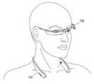
도 5a는 넥밴드부와 글래스부를 결합하여 목에 착용한 개념도.
도 5b는 이동 단말기를 넥밴드부와 글래스부로 분리하여 사용하는 개념도.
도 5c는 넥밴드부와 글래스부를 결합하여 두부에 착용한 개념도.
도 6은 넥밴드부와 글래스부의 전기적 연결을 설명하기 위한 개념도.
도 7은 도 6과 다른 구조의 전기적 연결을 설명하기 위한 개념도.
도 8a 및 도 8b는 각각 도 4에 도시된 Ⅷ 부분의 내부 구조를 나타내는 개념도.1 is a block diagram of a mobile terminal according to an embodiment of the present invention.
FIG. 2 is a perspective view of a mobile terminal according to an embodiment of the present invention, which is divided into a neckband portion and a glass portion. FIG.
3 is a plan view of the mobile terminal shown in FIG. 2, which is divided into a neckband portion and a glass portion.
FIG. 4 is a perspective view of a mobile terminal having a neckband unit and a glass unit shown in FIG. 2; FIG.
FIG. 5A is a conceptual view of a neckband unit and a glass unit combined to wear the neckband. FIG.
FIG. 5B is a conceptual view of using a mobile terminal separated from a neckband portion and a glass portion. FIG.
Fig. 5c is a conceptual view of a neck portion and a glass portion joined together and worn on the head portion. Fig.
6 is a conceptual view for explaining the electrical connection between the neck band part and the glass part;
7 is a conceptual view for explaining an electrical connection of another structure to that of FIG. 6;
8A and 8B are conceptual diagrams showing the internal structure of the portion VIII shown in FIG. 4;
이하, 첨부된 도면을 참조하여 본 명세서에 개시된 실시 예를 상세히 설명하되, 동일하거나 유사한 구성요소에는 동일·유사한 도면 부호를 부여하고 이에 대한 중복되는 설명은 생략하기로 한다. 이하의 설명에서 사용되는 구성요소에 대한 접미사 "모듈" 및 "부"는 명세서 작성의 용이함만이 고려되어 부여되거나 혼용되는 것으로서, 그 자체로 서로 구별되는 의미 또는 역할을 갖는 것은 아니다. 또한, 본 명세서에 개시된 실시 예를 설명함에 있어서 관련된 공지 기술에 대한 구체적인 설명이 본 명세서에 개시된 실시 예의 요지를 흐릴 수 있다고 판단되는 경우 그 상세한 설명을 생략한다. 또한, 첨부된 도면은 본 명세서에 개시된 실시 예를 쉽게 이해할 수 있도록 하기 위한 것일 뿐, 첨부된 도면에 의해 본 명세서에 개시된 기술적 사상이 제한되지 않으며, 본 발명의 사상 및 기술 범위에 포함되는 모든 변경, 균등물 내지 대체물을 포함하는 것으로 이해되어야 한다.Hereinafter, embodiments of the present invention will be described in detail with reference to the accompanying drawings, wherein like or similar elements are denoted by the same or similar reference numerals, and a duplicate description thereof will be omitted. The suffix "module" and " part "for the components used in the following description are given or mixed in consideration of ease of specification, and do not have their own meaning or role. In the following description of the embodiments of the present invention, a detailed description of related arts will be omitted when it is determined that the gist of the embodiments disclosed herein may be blurred. It is to be understood that both the foregoing general description and the following detailed description are exemplary and explanatory and are intended to provide further explanation of the invention as claimed. , ≪ / RTI > equivalents, and alternatives.
제1, 제2 등과 같이 서수를 포함하는 용어는 다양한 구성요소들을 설명하는데 사용될 수 있지만, 상기 구성요소들은 상기 용어들에 의해 한정되지는 않는다. 상기 용어들은 하나의 구성요소를 다른 구성요소로부터 구별하는 목적으로만 사용된다.Terms including ordinals, such as first, second, etc., may be used to describe various elements, but the elements are not limited to these terms. The terms are used only for the purpose of distinguishing one component from another.
어떤 구성요소가 다른 구성요소에 "연결되어"있다거나 "접속되어"있다고 언급된 때에는, 그 다른 구성요소에 직접적으로 연결되어 있거나 또는 접속되어 있을 수도 있지만, 중간에 다른 구성요소가 존재할 수도 있다고 이해되어야 할 것이다. 반면에, 어떤 구성요소가 다른 구성요소에 "직접 연결되어"있다거나 "직접 접속되어"있다고 언급된 때에는, 중간에 다른 구성요소가 존재하지 않는 것으로 이해되어야 할 것이다.It is to be understood that when an element is referred to as being "connected" or "connected" to another element, it may be directly connected or connected to the other element, . On the other hand, when an element is referred to as being "directly connected" or "directly connected" to another element, it should be understood that there are no other elements in between.
단수의 표현은 문맥상 명백하게 다르게 뜻하지 않는 한, 복수의 표현을 포함한다.The singular expressions include plural expressions unless the context clearly dictates otherwise.
본 출원에서, "포함한다" 또는 "가지다" 등의 용어는 명세서상에 기재된 특징, 숫자, 단계, 동작, 구성요소, 부품 또는 이들을 조합한 것이 존재함을 지정하려는 것이지, 하나 또는 그 이상의 다른 특징들이나 숫자, 단계, 동작, 구성요소, 부품 또는 이들을 조합한 것들의 존재 또는 부가 가능성을 미리 배제하지 않는 것으로 이해되어야 한다.In the present application, the terms "comprises", "having", and the like are used to specify that a feature, a number, a step, an operation, an element, a component, But do not preclude the presence or addition of one or more other features, integers, steps, operations, elements, components, or combinations thereof.
도 1은 본 발명의 일 실시예에 관련된 이동 단말기의 블록 구성도(block diagram)다.1 is a block diagram of a mobile terminal according to an embodiment of the present invention.
이동 단말기(100)는 무선 통신부(110), 입력부(120), 감지부(140), 출력부(150), 인터페이스부(160), 메모리(170), 제어부(180) 및 전원 공급부(190) 등을 포함할 수 있다. 도 1에 도시된 구성요소들은 이동 단말기를 구현하는데 있어서 필수적인 것은 아니어서, 본 명세서 상에서 설명되는 이동 단말기는 위에서 열거된 구성요소들 보다 많거나, 또는 적은 구성요소들을 가질 수 있다.The
보다 구체적으로, 상기 구성요소들 중 무선 통신부(110)는, 이동 단말기(100)와 무선 통신 시스템 사이, 이동 단말기(100)와 다른 이동 단말기(100) 사이, 또는 이동 단말기(100)와 외부서버 사이의 무선 통신을 가능하게 하는 하나 이상의 모듈을 포함할 수 있다. 또한, 상기 무선 통신부(110)는, 이동 단말기(100)를 하나 이상의 네트워크에 연결하는 하나 이상의 모듈을 포함할 수 있다.The
이러한 무선 통신부(110)는, 방송 수신 모듈(111), 이동통신 모듈(112), 무선 인터넷 모듈(113), 근거리 통신 모듈(114), 위치정보 모듈(115) 중 적어도 하나를 포함할 수 있다.The
입력부(120)는, 영상 신호 입력을 위한 카메라(121) 또는 영상 입력부, 오디오 신호 입력을 위한 마이크로폰(microphone, 122), 또는 오디오 입력부, 사용자로부터 정보를 입력받기 위한 사용자 입력부(123, 예를 들어, 터치키(touch key), 푸시키(mechanical key) 등)를 포함할 수 있다. 입력부(120)에서 수집한 음성 데이터나 이미지 데이터는 분석되어 사용자의 제어명령으로 처리될 수 있다.The
센싱부(140)는 이동 단말기 내 정보, 이동 단말기를 둘러싼 주변 환경 정보 및 사용자 정보 중 적어도 하나를 센싱하기 위한 하나 이상의 센서를 포함할 수 있다. 예를 들어, 센싱부(140)는 근접센서(141, proximity sensor), 조도 센서(142, illumination sensor), 터치 센서(touch sensor), 가속도 센서(acceleration sensor), 자기 센서(magnetic sensor), 중력 센서(G-sensor), 자이로스코프 센서(gyroscope sensor), 모션 센서(motion sensor), RGB 센서, 적외선 센서(IR 센서: infrared sensor), 지문인식 센서(finger scan sensor), 초음파 센서(ultrasonic sensor), 광 센서(optical sensor, 예를 들어, 카메라(121 참조)), 마이크로폰(microphone, 122 참조), 배터리 게이지(battery gauge), 환경 센서(예를 들어, 기압계, 습도계, 온도계, 방사능 감지 센서, 열 감지 센서, 가스 감지 센서 등), 화학 센서(예를 들어, 전자 코, 헬스케어 센서, 생체 인식 센서 등) 중 적어도 하나를 포함할 수 있다. 한편, 본 명세서에 개시된 이동 단말기는, 이러한 센서들 중 적어도 둘 이상의 센서에서 센싱되는 정보들을 조합하여 활용할 수 있다.The
출력부(150)는 시각, 청각 또는 촉각 등과 관련된 출력을 발생시키기 위한 것으로, 디스플레이부(151), 음향 출력부(152), 햅팁 모듈(153), 광 출력부(154) 중 적어도 하나를 포함할 수 있다. 디스플레이부(151)는 터치 센서와 상호 레이어 구조를 이루거나 일체형으로 형성됨으로써, 터치 스크린을 구현할 수 있다. 이러한 터치 스크린은, 이동 단말기(100)와 사용자 사이의 입력 인터페이스를 제공하는 사용자 입력부(123)로써 기능함과 동시에, 이동 단말기(100)와 사용자 사이의 출력 인터페이스를 제공할 수 있다.The
인터페이스부(160)는 이동 단말기(100)에 연결되는 다양한 종류의 외부 기기와의 통로 역할을 수행한다. 이러한 인터페이스부(160)는, 유/무선 헤드셋 포트(port), 외부 충전기 포트(port), 유/무선 데이터 포트(port), 메모리 카드(memory card) 포트, 식별 모듈이 구비된 장치를 연결하는 포트(port), 오디오 I/O(Input/Output) 포트(port), 비디오 I/O(Input/Output) 포트(port), 이어폰 포트(port) 중 적어도 하나를 포함할 수 있다. 이동 단말기(100)에서는, 상기 인터페이스부(160)에 외부 기기가 연결되는 것에 대응하여, 연결된 외부 기기와 관련된 적절할 제어를 수행할 수 있다.The
또한, 메모리(170)는 이동 단말기(100)의 다양한 기능을 지원하는 데이터를 저장한다. 메모리(170)는 이동 단말기(100)에서 구동되는 다수의 응용 프로그램(application program 또는 애플리케이션(application)), 이동 단말기(100)의 동작을 위한 데이터들, 명령어들을 저장할 수 있다. 이러한 응용 프로그램 중 적어도 일부는, 무선 통신을 통해 외부 서버로부터 다운로드 될 수 있다. 또한 이러한 응용 프로그램 중 적어도 일부는, 이동 단말기(100)의 기본적인 기능(예를 들어, 전화 착신, 발신 기능, 메시지 수신, 발신 기능)을 위하여 출고 당시부터 이동 단말기(100)상에 존재할 수 있다. 한편, 응용 프로그램은, 메모리(170)에 저장되고, 이동 단말기(100) 상에 설치되어, 제어부(180)에 의하여 상기 이동 단말기의 동작(또는 기능)을 수행하도록 구동될 수 있다.In addition, the
제어부(180)는 상기 응용 프로그램과 관련된 동작 외에도, 통상적으로 이동 단말기(100)의 전반적인 동작을 제어한다. 제어부(180)는 위에서 살펴본 구성요소들을 통해 입력 또는 출력되는 신호, 데이터, 정보 등을 처리하거나 메모리(170)에 저장된 응용 프로그램을 구동함으로써, 사용자에게 적절한 정보 또는 기능을 제공 또는 처리할 수 있다.In addition to the operations related to the application program, the
또한, 제어부(180)는 메모리(170)에 저장된 응용 프로그램을 구동하기 위하여, 도 1a와 함께 살펴본 구성요소들 중 적어도 일부를 제어할 수 있다. 나아가, 제어부(180)는 상기 응용 프로그램의 구동을 위하여, 이동 단말기(100)에 포함된 구성요소들 중 적어도 둘 이상을 서로 조합하여 동작시킬 수 있다.In addition, the
전원공급부(190)는 제어부(180)의 제어 하에서, 외부의 전원, 내부의 전원을 인가 받아 이동 단말기(100)에 포함된 각 구성요소들에 전원을 공급한다. 이러한 전원공급부(190)는 배터리를 포함하며, 상기 배터리는 내장형 배터리 또는 교체가능한 형태의 배터리가 될 수 있다.The
상기 각 구성요소들 중 적어도 일부는, 이하에서 설명되는 다양한 실시 예들에 따른 이동 단말기의 동작, 제어, 또는 제어방법을 구현하기 위하여 서로 협력하여 동작할 수 있다. 또한, 상기 이동 단말기의 동작, 제어, 또는 제어방법은 상기 메모리(170)에 저장된 적어도 하나의 응용 프로그램의 구동에 의하여 이동 단말기 상에서 구현될 수 있다.At least some of the components may operate in cooperation with one another to implement a method of operation, control, or control of a mobile terminal according to various embodiments described below. In addition, the operation, control, or control method of the mobile terminal may be implemented on the mobile terminal by driving at least one application program stored in the
이하에서는 도 2 내지 도 4를 참조하여, 종래와 다른 구조를 갖는 본 발명의 이동 단말기(200)를 설명한다.Hereinafter, a
이동 단말기(200)는 사용자가 주로 손에 쥐고 사용하는 차원을 넘어서, 신체에 착용할 수 있는 웨어러블 디바이스(wearable device)로 확장될 수 있다. 이러한 웨어러블 디바이스에는 스마트 워치(smart watch), 스마트 글래스(smart glass), HMD(head mounted display) 등이 있다. 이하, 웨어러블 디바이스로 확장된 이동 단말기(200)의 예들에 대하여 설명하기로 한다.The
웨어러블 디바이스는 다른 이동 단말기와 데이터를 상호 교환(또는 연동) 가능하게 이루어질 수 있다. 근거리 통신 모듈(114, 도 1 참조)은, 이동 단말기(200)(100) 주변에 통신 가능한 웨어러블 디바이스를 감지(또는 인식)할 수 있다. 나아가, 제어부(180, 도 1 참조)는 감지된 웨어러블 디바이스가 다른 이동 단말기와 통신하도록 인증된 디바이스인 경우, 다른 이동 단말기에서 처리되는 데이터의 적어도 일부를, 근거리 통신 모듈(114, 도 1 참조)을 통하여 웨어러블 디바이스로 전송할 수 있다. 따라서, 사용자는 다른 이동 단말기에서 처리되는 데이터를 웨어러블 디바이스를 통하여 이용할 수 있다. 예를 들어, 다른 이동 단말기에 전화가 수신된 경우 웨어러블 디바이스를 통해 전화 통화를 수행하거나, 다른 이동 단말기에 메시지가 수신된 경우 웨어러블 디바이스를 통해 상기 수신된 메시지를 확인하는 것이 가능하다.The wearable device can be made to be able to exchange (or interlock) data with other mobile terminals. The near field communication module 114 (see FIG. 1) may detect (or recognize) a wearable device capable of communicating with the mobile terminal 200 (100). 1), when the detected wearable device is a device authenticated to communicate with another mobile terminal, transmits at least a portion of the data processed by the other mobile terminal to the short range communication module 114 (see FIG. 1) To the wearable device. Thus, the user can use the data processed by the other mobile terminal through the wearable device. For example, it is possible to make a phone call through a wearable device when a telephone is received at another mobile terminal, or to confirm the received message via a wearable device when a message is received at another mobile terminal.
도 2는 본 발명의 일 실시예에 관련된 이동 단말기(200)를 넥밴드부(210)와 글래스부(230)로 나누어 도시한 사시도다. 도 3은 도 2에 도시된 이동 단말기(200)를 넥밴드부(210)와 글래스부(230)로 나누어 도시한 평면도다. 도 4는 도 2에 도시된 넥밴드부(210)와 글래스부(230)를 결합한 이동 단말기(200)의 사시도다.FIG. 2 is a perspective view of a
이동 단말기(200)는, 목걸이처럼 사용자의 목에 걸어 사용하는 넥밴드부(210)와 안경처럼 사용자의 두부에 착용하는 글래스부(230)를 포함한다.The
넥밴드부(210)는 사용자의 목에 걸도록 형성된다. 도 2에 도시된 넥밴드부(210)는 'U'자 형태로 형성되는 것을 예시하고 있다. 넥밴드부(210)는 플렉서블 재질로 형성될 수 있다. 이에 따라 사용자는 넥밴드부(210)를 벌려 'U'자 형태의 안쪽에 목을 위치시킬 수 있고, 사용자가 넥밴드부(210)를 놓으면 상기 넥밴드부(210)는 벌어지기 전 상태로 복원된다. 넥밴드부(210)는 이러한 과정을 통해 사용자의 목에 착용된다.The
글래스부(230)는 사용자의 두부에 착용 가능하도록 이루어지는 프레임(231)을 구비한다. 프레임(231)은 사용자의 두부에 장착되었을 때, 두부의 전면에서 양측의 귀를 향해 연장되는 'U'자 형태로 형성될 수 있다. 다만, 프레임(231)의 형태가 반드시 이에 한정되는 것은 아니고, 사용자의 두부에 착용 가능한 다른 형태로 형성될 수도 있다. 프레임(231)은 글래스부(230)에서 실질적으로 안경테의 기능을 한다. 프레임(231)은 글래스부(230)의 착용이 용이하도록 플렉서블 재질로 형성될 수 있다.The
프레임(231)에서 사용자의 피부와 접촉하는 부분은 착용감을 향상시키도록 실리콘 재질로 형성될 수 있다. 상기 프레임(231)에서 나머지 부분은 안테나로 작동하도록 메탈 재질로 형성될 수 있다. 메탈 재질 부분은 용도에 맞는 안테나를 구현하기 위해 적어도 일부가 패턴의 형태로 분할될 수 있다.The portion of the
글래스부(230)는 상기 프레임(231)에 설치되는 입출력 모듈(232)을 구비한다. 입출력 모듈(232)은 도 1에서 설명한 입력부와 출력부를 포함하는 것으로, 입출력 모듈(232)은 디스플레이부(232a)와 터치 입력부(232b)를 포함할 수 있다. 디스플레이부(232a)는, 사용자의 눈 앞에 배치되어 상기 사용자에게 시각 정보를 제공한다. 그리고, 터치 입력부(232b)는 터치 입력을 인가받도록 형성된다. 터치 입력부(232b)는 디스플레이부(232a)로부터 프레임(231)을 따라 연장되어 형성된다. 디스플레이부(232a)는 실질적으로 두분의 전면에 배치될 수 있고, 터치 입력부(232b)는 실질적으로 두부의 측면에 배치될 수 있다.The
디스플레이부(232a)는 프리즘을 이용하여 사용자의 눈으로 이미지를 투사할 수 있다. 또한, 사용자가 투사된 이미지와 전방의 일반 시야(사용자가 눈을 통하여 바라보는 범위)를 함께 볼 수 있도록, 프리즘은 투광성으로 형성될 수 있다.The
이처럼, 디스플레이부(232a)를 통하여 출력되는 영상은, 일반 시야와 오버랩(overlap)되어 보여질 수 있다. 이동 단말기(200)는 이러한 디스플레이의 특성을 이용하여 현실의 이미지나 배경에 가상 이미지를 겹쳐서 하나의 영상으로 보여주는 증강현실(Augmented Reality, AR)을 제공할 수 있다.As described above, the image output through the
글래스부(230)는 상기 프레임(231)에 설치되는 카메라 모듈(233)을 더 구비할 수 있다. 카메라 모듈(233)은 좌안 및 우안 중 적어도 하나에 인접하게 배치되어, 전방의 영상을 촬영하도록 형성된다. 카메라 모듈(233)은 눈에 인접하여 위치하므로, 카메라 모듈(233)은 사용자가 바라보는 장면을 영상으로 획득할 수 있다.The
본 발명에서 입출력 모듈(232)과 카메라 모듈(233)은 글래스부(230)의 무게가 한쪽으로 집중되는 것을 방지하도록 상기 프레임(231)의 중앙을 기준으로 서로 다른 쪽에 설치될 수 있다. 그러나, 입출력 모듈(232)과 카메라 모듈(233)의 위치는 변경될 수 있다. 예를 들어, 카메라 모듈(233)은 프레임(231)의 중앙에 배치될 수 있다.In the present invention, the input /
입출력 모듈(232)에는 글래스부(230)의 동작을 제어하는 제어부(미도시)가 내장될 수 있다. 제어부는 사용자의 터치 입력에 근거하여 디스플레이부(232a) 또는 카메라 모듈(233)을 작동시킬 수 있다. 제어부는, 예를 들어 마이크(215)로 컨트롤러 유닛을 포함할 수 있다.The input /
넥밴드부(210)와 글래스부(230)는 서로 결합 또는 분리 가능하게 형성된다.The
넥밴드부(210)는 적어도 일부가 글래스부(230)의 프레임(231)에 대응되도록 형성되는 수용홈(211)을 구비한다. 글래스부(230)는, 프레임(231)의 양 단부를 각각 상기 수용홈(211)에 삽입하여 상기 넥밴드부(210)와 결합되고, 상기 프레임(231)의 양 단부를 상기 수용홈(211)으로부터 인출하여 상기 넥밴드부(210)와 분리된다. 넥밴드부(210)와 글래스부(230)가 서로 결합되면, 이동 단말기(200)는 하나의 바디로 형성된다. 넥밴드부(210)와 글래스부(230)가 서로 분리되면, 이동 단말기(200)는 두 개의 바디로 형성된다.The
도 2와 도 3은 분리된 상태의 넥밴드부(210)와 글래스부(230)를 도시한 것이다. 넥밴드부(210)와 글래스부(230)는 서로 결합되어 환형의 단말기 본체를 형성한다. 도 4는 결합된 상태의 넥밴드부(210)와 글래스부(230)를 도시한 것이다. 단말기 본체는 사용자의 목 또는 두부의 크기에 맞게 조절되도록 길이를 연장하거나 단축 가능하게 형성될 수 있다.FIGS. 2 and 3 show the
도 2와 도 3을 참조하면, 넥밴드부(210)는 각각 양 단부에 수용홈(211)으로부터 확장되어 형성되는 제1수용부(212a)와 제2수용부(212b)를 구비할 수 있다. 제1수용부(212a)는 넥밴드부(210)의 일 단부에 형성되고, 제2수용부(212b)는 넥밴드부(210)의 타 단부에 형성된다. 도 4에 도시한 바와 같이 넥밴드부(210)와 글래스부(230)가 서로 결합되면, 입출력 모듈(232)의 적어도 일부가 상기 제1수용부(212a)에 삽입되고, 상기 카메라 모듈(233)의 적어도 일부가 상기 제2수용부(212b)에 삽입된다.Referring to FIGS. 2 and 3, the
도 2의 A 부분을 참조하면, 넥밴드부(210)는 제1수용부(212a)에서 돌출되어 형성되는 커넥터(213)를 구비한다. 그리고, 입출력 모듈(232)은 상기 커넥터(213)에 대응하는 포트(236)를 구비한다. 입출력 모듈(232)이 제1수용부(212a)에 삽입되면, 도 4의 B 부분에 도시된 바와 같이 커넥터(213)는 포트(236)에 삽입된다. 커넥터(213)와 포트(236)에 의해 넥밴드부(210)와 글래스부(230)가 전기적으로 연결될 수 있다.Referring to part A of FIG. 2, the
본 발명에서 넥밴드부(210)는 주 전원 공급부(미도시)를 구비한다. 상기 주 전원 공급부는 넥밴드부(210)에서 필요로 하는 전력을 공급할 뿐만 아니라, 글래스부(230)에서 필요로 하는 전력을 공급할 수 있다.In the present invention, the
동일한 무게의 물체를 안경과 같은 형태로 썼을 때와 목에 걸었을 때를 비교하면, 인체는 물체를 목에 걸었을 때 피로감을 덜 느낀다. 물체를 목에 걸면 상기 물체를 목과 어깨의 내부 근육으로 지지하는 반면, 물체를 안경과 같은 형태로 쓰면 귀와 코로 상기 물체를 지지하여야 하기 때문이다.Compared to wearing glasses of the same weight in the form of eyeglasses and walking in the neck, the human body feels less tired when the object is placed on the neck. When an object is placed on the neck, the object is supported by the inner muscles of the neck and shoulders, whereas if the object is used in the form of glasses, the object must be supported by the ear and nose.
이러한 점에 착안하여, 본 발명은 사용자에게 전달되는 피로도를 저감하기 위해 이동 단말기(200)의 무게 중 큰 비중을 차지하는 주 전원 공급부를 넥밴드부(210)의 내부에 배치하였다. 넥밴드부(210)는 목에 걸어 사용하므로, 글래스부(230)에 비해 더 크고 더 무겁게 형성되어도 이동 단말기(200)의 사용에 불편함을 초래하지 않는다. 따라서, 주 전원 공급부가 글래스부(230)에 설치되는 경우와 주 전원 공급부가 넥밴드부(210)에 설치되는 경우를 비교하면, 후자의 경우가 사용자에게 전달하는 피로도를 저감하는 것은 물론 이동 단말기(200)에서 필요로 하는 전력을 충분히 확보할 수 있다.In order to reduce the fatigue transmitted to the user, the main power supply part occupying a large weight of the weight of the
글래스부(230)는 넥밴드부(210)의 내부에 내장된 주 전원 공급부로부터 전력을 공급받도록 넥밴드부(210)와 전기적으로 연결 가능하게 형성된다. 도 3을 참조하면, 글래스부(230)는 양 단부에 충전핀(234)을 구비하고, 넥밴드부(210)는 상기 충전핀(234)에 대응되는 충전단자(214)를 구비한다. 충전핀(234)은 프레임(231)에 형성될 수 있고, 충전단자(214)는 수용홈(211)에 형성될 수 있다. 따라서, 도 4에 도시된 바와 같이 프레임(231)이 수용홈(211)에 삽입되면, 충전핀(234)과 충전단자(214)를 서로 접촉되도록 이루어진다. 충전핀(234)과 충전단자(214)의 구조 또는 배치는 이상에서 설명한 바에 한정되는 것은 아니다. 예를 들어, 충전핀(234)이 넥밴드부(210)에 형성되고, 충전단자(214)가 글래스부(230)에 형성될 수 있다.The
커넥터(213)와 포트(236)는 넥밴드부(210)와 글래스부(230) 사이의 데이터를 전송하는 역할을 하며, 충전핀(234)과 충전단자(214)는 주 전원 공급부로부터 부 전원 공급부(미도시)로 전력을 공급하는 역할을 하는 점에서 서로 구분된다. 그러나, 본 발명에서 각각의 구조와 배치는 반드시 앞서 설명한 바에 한정되는 것은 아니고 서로 바뀔 수 있다.The
글래스부(230)에는 넥밴드부(210)와 전기적으로 연결되지 않은 상태에서도 작동 가능하도록 내부에 부 전원 공급부를 구비할 수 있다. 부 전원 공급부는 주 전원 공급부에 비해 소용량으로 형성된다. 넥밴드부(210)와 글래스부(230)가 결합되면, 부 전원 공급부는 주 전원 공급부로부터 공급되는 전력에 의해 충전될 수 있다. 전력의 공급은 상기 충전핀(234)과 충전단자(214)를 통해 이루어질 수 있다.The
본 발명은, 이동 단말기(200)의 착용에 의해 인체의 일부에 피로도가 집중되는 것을 방지하는 구조를 갖는다. 구체적으로, 넥밴드부(210)와 글래스부(230)에는 이동 단말기(200)의 부품들이 서로 나누어 실장된다. 예를 들어, 글래스부(230)는 상기 글래스부(230)의 작동을 가능하게 하는 최소한의 구성요소들만을 구비하고, 그 이외에 대부분의 다른 구성요소들은 넥밴드부(210)에 구비될 수 있다.The present invention has a structure for preventing fatigue from being concentrated on a part of a human body by wearing the mobile terminal (200). Particularly, the components of the
프레임(231), 입출력 모듈(232), 카메라 모듈(233), 제어부, 부 전원 공급부는, 넥밴드부(210)와 독립적으로 글래스부(230)의 작동을 가능하게 하는 최소한의 구성요소들이다. 상기 구성요소들 외에 반드시 글래스부(230)에 설치되어야 하는 구성요소들은 상기 글래스부(230)에 추가될 수 있다. 반드시 글래스부(230)에 설치되어야 하는 구성요소는, 예를 들어 혈류량(photoplethysmography) 측정 센서나 심전도(electrocardiogram) 측정 센서와 같은 바이오 센서(235)를 포함한다. 혈류량 측정 센서는 적외선 LED와 수광부를 포함할 수 있고, 심전도 측정 센서는 전극을 포함할 수 있다. 각각의 바이오 센서(235)는 피부에 접촉하여 혈류의 변화나 미세한 전기를 인식하므로 사용자의 피부를 통해 전달되는 생체 신호를 감지한다. 본 발명에서 글래스부(230)에 설치되는 센서는 반드시 바이오 센서에 한정되는 것은 아니고, 글래스부(230)에 설치 가능한 모든 종류의 센서를 포함할 수 있다.The
넥밴드부(210)와 글래스부(230)에서 사용자의 피부에 고정적으로 접촉되는 부분은 글래스부(230)이며, 보다 구체적으로는 프레임(231)이다. 프레임(231)은 사용자의 귀에 거치되므로, 사용자의 두부에 고정적으로 접촉된다. 이에 반해 넥밴드부(210)는 사용자의 피부에 고정적으로 접촉되지 않는다. 따라서, 바이오 센서(235)는 반드시 글래스부(230)에 설치되어야 하는 구성요소다.The portion of the
그러나, 그 이외에 이동 단말기(200)를 구현하기 위한 대부분의 구성요소들은 넥밴드부(210)에 설치된다. 예를 들어, 넥밴드부(210)는 마이크(215), 음향 출력 모듈(216), 이어잭 소켓(미도시), 주 제어부(미도시) 및 무선 통신부(110, 도 1 참조) 중 적어도 하나를 구비할 수 있다.However, most of the components for realizing the
마이크(215)는 상기 넥밴드부(210)의 일 단부에 설치되는 제1마이크(215)와 타 단부에 설치되는 제2마이크(215)를 포함할 수 있다. 제1마이크(215)와 제2마이크(215)는 사용자의 음성 이외의 잡음을 제거하도록 서로 연계되어 작동할 수 있다.The
음향 출력 모듈(216)은 라우드 스피커와 골전도 스피커를 포함할 수 있다. 라우드 스피커는 넥밴드부(210)의 일측에 설치되고, 골전도 스피커는 넥밴드부(210)의 타측이 설치되는 것도 가능하다. 골전도 스피커는 두개골을 진동시켜 소리를 전달하는 방식의 스피커이다. 골전도 스피커는 넥밴드부(210)로부터 인출 가능하게 형성될 수도 있다.The
주 제어부는 제한된 기능만을 제어하는 글래스부(230)의 제어부와 달리 이동 단말기(200)의 전반적인 기능을 제어할 수 있다.The main control unit can control the overall function of the
무선 통신부는 블루투스, 와이파이 등의 통신 모듈을 포함할 수 있다.The wireless communication unit may include a communication module such as Bluetooth, Wi-Fi, or the like.
이러한 구성요소들은 반드시 글래스부(230)에 설치되어야 하는 것들은 아니다. 따라서, 마이크(215), 스피커, 이어잭 소켓, 주 제어부 및 무선 통신부가 모두 넥밴드부(210)에 구비되는 것이 바람직하다.These components are not necessarily those to be installed in the
다만, 글래스부(230)와 넥밴드부(210)의 전기적 연결 방식이 무선 연결 방식인 경우에는, 글래스부(230)와 넥밴드부(210)는 모두 무선 통신부를 포함할 수 있다. 상기 무선 통신부를 통해 글래스부(230)와 넥밴드부(210)는 서로 데이터를 주고 받을 수 있다. 그리고, 전기적 연결에 의해 글래스부(230)에서 활용 가능한 기능은 넥밴드부(210)에 포함된 기능들로까지 확장된다.However, when the
본 발명은 구성요소들의 분산 배치를 통해 글래스 타입 단말기에 비하여 소형화 및 경량화된 글래스부(230)를 구현할 수 있다. 글래스부(230)는 부 전원 공급부에서 공급되는 전력을 이용해 넥밴드부(210)와 독립적으로 작동할 수 있다. 다만, 부 전원 공급부의 용량은 주 전원 공급부의 용량보다 작으므로, 장시간 글래스부(230)의 사용을 위해서는 상기 주 전원 공급부로부터 공급되는 전력을 이용하여 부 전원 공급부를 충전하는 것이 바람직하다.The present invention can realize a miniaturized and lightened
글래스부(230)는 작동에 필요한 최소한의 구성요소만을 구비하고 대부분의 구성요소들은 넥밴드부(210)에 구비되므로, 글래스부(230)에서 실행 가능한 기능은 글래스부(230)와 넥밴드부(210)의 전기적 연결에 의해 확장될 수 있다. 예를 들어, 스피커가 넥밴드부(210)에만 설치되는 경우, 글래스부(230)만을 넥밴드부(210)와 독립적으로 사용하면 상기 글래스부(230)에서는 스피커 기능을 이용할 수 없다. 그러나, 글래스부(230)와 넥밴드부(210)가 전기적으로 연결되면, 글래스부(230)의 터치 입력부(232b)를 통해 인가되는 입력에 근거하여 스피커 기능을 활성화 할 수 있다.Since the
이하에서는 넥밴드부(210)와 글래스부(230)를 결합 또는 분리하여 착용한 이동 단말기(200)에 대하여 각각 설명한다.Hereinafter, the
도 5a는 넥밴드부(210)와 글래스부(230)를 결합하여 목에 착용한 개념도다.FIG. 5A is a concept to be worn on the neck by joining the
넥밴드부(210)와 글래스부(230)는 서로 결합되어 환형의 단말기 바디를 형성한다. 환형의 단말기 바디는 도 5a에 도시한 바와 같이 사용자의 목에 걸 수 있다. 따라서, 비사용시 휴대와 보관을 위한 별도의 케이스가 없어도, 글래스부(230)는 사용자의 목에 걸려 있는 넥밴드부(210)에 결합하여 휴대하고 보관할 수 있다.The
넥밴드부(210)와 글래스부(230)는 환형의 단말기 바디를 형성하므로 상기 넥밴드부(210)와 글래스부(230)의 결합이 해제되지 않는 한, 본 발명의 이동 단말기(200)는 안전하게 보관될 수 있다.Since the
이동 단말기(200)는 분실을 방지하기 위해 탄성부재를 더 포함할 수 있다. 탄성부재는 수용홈(211)의 내주면에 설치되고, 수용홈(211)으로부터 글래스부(230)의 임의적인 이탈을 방지하도록 프레임(231)을 가압한다. 바람직하게는 탄성부재가 수용홈(211)의 양쪽 내주면에 설치되어 프레임(231)을 양쪽에서 가압할 수 있다. 탄성부재에 의해 글래스부(230)는 수용홈(211)으로부터 임의적으로 이탈되지 않으므로, 이동 단말기(200)는 분실을 방지할 수 있다.The
도 5b는 이동 단말기(200)를 넥밴드부(210)와 글래스부(230)로 분리하여 사용하는 개념도다.5B is a concept in which the
도 5b에 도시된 사용 상태도는 본 발명에서 구현하고자 하는 바람직한 본 발명의 사용 상태를 도시한 것이다. 넥밴드부(210)는 목에 걸어 사용하고, 글래스부(230)는 두부에 착용하여 사용한다.The use state diagram shown in FIG. 5B shows a preferred use state of the present invention to be implemented in the present invention. The
넥밴드부(210)와 글래스부(230)는 서로 전기적으로 연결되되, 전기적으로 연결되는 방법은 어느 것이나 적용될 수 있다. 예를 들어, 넥밴드부(210)와 글래스부(230)는 블루투스를 이용하여 무선으로 페어링될 수 있다.The
사용자는 이동 단말기(200)의 사용을 중단하고자 하는 경우, 도 5a에 도시된 바와 같이 글래스부(230)를 넥밴드에 결합하여 보관할 수 있다.When the user desires to stop the use of the
도 5c는 넥밴드부(210)와 글래스부(230)를 결합하여 두부에 착용한 개념도다.5C is a concept that is worn on the head by joining the
넥밴드부(210)와 글래스부(230)가 서로 결합된 상태에서, 이동 단말기(200)를 두부에 착용하는 것도 가능하다. 환형의 단말기 바디를 헤드밴드 형태로 두부에 착용할 수 있다. 단말기 본체는 사용자의 목 또는 두부의 크기에 맞게 조절되도록 길이를 연장하거나 단축하는 것이 가능하게 형성될 수 있다.It is also possible to wear the
이하에서는 넥밴드부(210)와 글래스부(230)의 전기적 연결에 대하여 설명한다.Hereinafter, the electrical connection between the
도 6은 넥밴드부(210)와 글래스부(230)의 전기적 연결을 설명하기 위한 개념도다.6 is a conceptual diagram for explaining the electrical connection between the
이동 단말기(200)는 넥밴드부(210)와 글래스부(230)가 서로 분리된 상태에서 상기 넥밴드부(210)와 상기 글래스부(230)를 연결하는 케이블(250)을 더 포함할 수 있다. 케이블(250)은, 도 6에 도시된 바와 같이 넥밴드부(210)의 커넥터(213)와 글래스부(230)의 포트(236)를 연결할 수 있다.The
케이블(250)은 주 전원 공급부로부터 부 전원 공급부로 전력을 공급할 수 있고, 넥밴드부(210)와 글래스부(230) 사이의 데이터 전송을 담당할 수 있다.The
도 7은 도 6과 다른 구조의 전기적 연결을 설명하기 위한 개념도다.7 is a conceptual diagram for explaining an electrical connection of a structure different from that of FIG.
넥밴드부(210)는 사용자의 목에 걸었을 때 상기 목의 뒷부분에 배치되는 외부면에 커넥터(217)를 구비한다. 그리고, 글래스부(230)는 커넥터(217)를 통해 상기 넥밴드부(210)와 전기적으로 연결 가능하도록 형성되는 단자부를 양 단부에 각각 구비한다. 커넥터(217)와 상기 단자부는 상기 커넥터(217)로부터 두 갈래로 분할되어 상기 단자부로 연장되는 케이블(260)에 의해 서로 연결된다.The
케이블(260)은 앞서 설명한 바와 마찬가지로 주 전원 공급부로부터 부 전원 공급부로 전력을 공급할 수 있고, 넥밴드부(210)와 글래스부(230) 사이의 데이터 전송을 담당할 수 있다.The
도 6 및 도 7에서 설명한 바와 달리, 넥밴드부(210)와 글래스부(230)는 무선으로 연결되는 것도 가능하다. 넥밴드부(210)와 글래스부(230)는 각각 무선 통신부를 포함하고, 무선 통신부는 예를 들어 블루투스 방식을 이용할 수 있다. 다만, 넥밴브부(210)와 글래스부(230)의 무선 통신 방식이 반드시 블루투스에 한정되는 것은 아니다.6 and 7, it is also possible that the
이하에서는 주 전원 공급부를 충전하기 위한 구조에 대하여 설명한다.Hereinafter, a structure for charging the main power supply unit will be described.
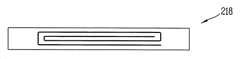
도 8a 및 도 8b는 각각 도 4에 도시된 Ⅷ 부분의 내부 구조를 나타내는 개념도다.8A and 8B are conceptual diagrams showing the internal structure of the portion VIII shown in FIG. 4, respectively.
넥밴드부(210)의 주 전원 공급부는 충전포트(미도시)를 통해 유선으로 충전기와 연결되어 전력을 공급받을 수 있다. 이와 달리, 주 전원 공급부는 무선충전기로부터 무선으로 전력을 공급받는 것도 가능하다.The main power supply unit of the
도 8a 와 도 8b은 무선으로 전력을 공급받는 구조를 설명하기 위한 것이다. 넥밴드부(210)는 외부의 무선 충전기로부터 무선으로 공급받아 상기 주 전원 공급부를 충전하도록 내부에 무선 충전 코일(218, 219)을 구비할 수 있다.8A and 8B illustrate a structure for receiving power wirelessly. The
도 8a는 연성인쇄회로기판(FPBC)을 이용하여 무선 충전 코일(218)을 구현한 것으로 도시한 것이다. 도 8b는 넥밴드부(210)의 내부에 축을 두고 그 축에 무선 충전 코일(219)을 감은 구조를 도시한 것이다. 각각의 무선 충전 코일(218, 219)들은 넥밴드부(210) 내부의 메인 인쇄회로기판(미도시)에 전기적으로 연결되어 작동할 수 있다.8A shows a
이상에서 설명된 이동 단말기는 상기 설명된 실시예들의 구성과 방법에 한정되는 것이 아니라, 상기 실시예들은 다양한 변형이 이루어질 수 있도록 각 실시예들의 전부 또는 일부가 선택적으로 조합되어 구성될 수도 있다.The mobile terminal described above is not limited to the configuration and the method of the embodiments described above, but the embodiments may be configured by selectively combining all or a part of each embodiment so that various modifications can be made.
Claims (18)
Translated fromKorean사용자의 두부(頭部)에 착용 가능하도록 이루어지는 프레임과 상기 프레임에 설치되는 입출력 모듈을 구비하고, 상기 주 전원 공급부로부터 전력을 공급받도록 상기 넥밴드부와 전기적으로 연결 가능하게 형성되는 글래스부를 포함하며,
상기 넥밴드부는 적어도 일부가 상기 프레임에 대응되도록 형성되는 수용홈을 구비하고,
상기 글래스부는, 상기 프레임의 양 단부를 각각 상기 수용홈에 삽입하여 상기 넥밴드부와 결합되며, 상기 프레임의 양 단부를 상기 수용홈으로부터 인출하여 상기 넥밴드부와 분리되는 것을 특징으로 하는 이동 단말기.A neck band formed on the neck of the user and having a main power supply; And
And a glass part electrically connected to the neck band part so as to receive power from the main power supply part, wherein the frame part includes a frame which is worn on a head of a user and an input / output module provided on the frame,
Wherein the neck band portion has a receiving groove formed so that at least a portion thereof corresponds to the frame,
Wherein the glass part is engaged with the neck band part by inserting both ends of the frame into the receiving groove and pulls both ends of the frame from the receiving groove to separate from the neck band part.
상기 글래스부는 상기 넥밴드부와 전기적으로 연결되지 않은 상태에서도 작동 가능하도록 내부에 부 전원 공급부를 구비하며,
상기 넥밴드부와 상기 글래스부가 결합되면, 상기 부 전원 공급부는 상기 주 전원 공급부로부터 공급되는 전력에 의해 충전되는 것을 특징으로 하는 이동 단말기.The method according to claim 1,
Wherein the glass portion has a negative power supply portion therein so as to be operable even when the glass portion is not electrically connected to the neckband portion,
Wherein when the neckband unit and the glass unit are coupled, the sub power supply unit is charged by the power supplied from the main power supply unit.
상기 넥밴드부와 상기 글래스부 중 어느 하나는 충전핀을 구비하고,
상기 넥밴드부와 상기 글래스부 중 다른 하나는 상기 충전핀에 대응하는 충전단자를 구비하며,
상기 프레임이 상기 수용홈에 삽입되면, 상기 충전핀과 상기 충전단자는 서로 접촉되도록 이루어지는 것을 특징으로 하는 이동 단말기.The method according to claim 1,
Wherein one of the neck band portion and the glass portion has a charging pin,
And the other of the neckband part and the glass part has a charging terminal corresponding to the charging pin,
Wherein when the frame is inserted into the receiving groove, the charging pin and the charging terminal are brought into contact with each other.
상기 글래스부는 상기 프레임에 설치되는 카메라 모듈을 더 구비하고,
상기 입출력 모듈과 상기 카메라 모듈은 상기 글래스부의 무게가 한쪽으로 집중되는 것을 방지하도록 상기 프레임의 중앙을 기준으로 서로 다른 쪽에 설치되는 것을 특징으로 하는 이동 단말기.The method according to claim 1,
Wherein the glass part further comprises a camera module installed in the frame,
Wherein the input / output module and the camera module are installed on opposite sides of a center of the frame to prevent the weight of the glass part from being concentrated on one side.
상기 넥밴드부는 각각 양 단부에 상기 수용홈으로부터 확장되어 형성되는 제1수용부와 제2수용부를 구비하고,
상기 넥밴드부와 상기 글래스부가 서로 결합되면, 상기 입출력 모듈의 적어도 일부가 상기 제1수용부에 삽입되고 상기 카메라 모듈의 적어도 일부가 상기 제2수용부에 삽입되는 것을 특징으로 하는 이동 단말기.5. The method of claim 4,
Wherein the neck band portion includes a first receiving portion and a second receiving portion formed at both ends of the neck band portion so as to extend from the receiving groove,
Wherein at least a part of the input / output module is inserted into the first accommodating portion and at least a part of the camera module is inserted into the second accommodating portion when the neckband portion and the glass portion are coupled with each other.
상기 넥밴드부는 상기 제1수용부에서 돌출되어 형성되는 커넥터를 구비하고,
상기 입출력 모듈은 상기 커넥터에 대응하는 포트를 구비하며,
상기 입출력 모듈이 상기 제1수용부에 삽입되면, 상기 커넥터는 상기 포트에 삽입되도록 이루어지는 것을 특징으로 하는 이동 단말기.6. The method of claim 5,
Wherein the neckband portion includes a connector protruding from the first housing portion,
The input / output module includes a port corresponding to the connector,
And the connector is inserted into the port when the input / output module is inserted into the first accommodating portion.
상기 넥밴드부와 상기 글래스부가 서로 분리된 상태에서 상기 넥밴드부와 상기 글래스부를 연결하는 케이블을 더 포함하는 것을 특징으로 하는 이동 단말기.The method according to claim 1,
Further comprising a cable connecting the neckband part and the glass part in a state where the neckband part and the glass part are separated from each other.
상기 넥밴드부는 사용자의 목에 걸었을 때 상기 목의 뒷부분에 배치되는 외부면에 커넥터를 구비하고,
상기 글래스부는 상기 커넥터를 통해 상기 넥밴드부와 전기적으로 연결 가능하도록 형성되는 단자부를 양 단부에 각각 구비하며,
상기 커넥터와 상기 단자부는 상기 커넥터로부터 두 갈래로 분할되어 상기 단자부로 연장되는 케이블에 의해 서로 연결되는 것을 특징으로 하는 이동 단말기.The method according to claim 1,
Said neckband portion having a connector on an outer surface disposed on a rear portion of said neck when said neckband portion is hooked to a user's neck,
Wherein the glass portion has terminal portions formed at both ends thereof so as to be electrically connected to the neckband portion through the connector,
Wherein the connector and the terminal portion are connected to each other by a cable extending from the connector into two portions and extending to the terminal portion.
상기 넥밴드부와 상기 글래스부는 서로 결합되어 환형의 단말기 본체를 형성하는 것을 특징으로 하는 이동 단말기.The method according to claim 1,
Wherein the neckband part and the glass part are coupled to each other to form an annular terminal body.
상기 글래스부는 사용자의 목에 걸려 있는 상기 넥밴드부에 결합하여 휴대하도록 이루어지는 것을 특징으로 하는 이동 단말기.10. The method of claim 9,
Wherein the glass part is coupled to the neckband part hanging on the neck of the user and carried.
상기 단말기 본체는 사용자의 목 또는 두부의 크기에 맞게 조절되도록 길이를 연장하거나 단축하는 것이 가능하게 형성되는 것을 특징으로 하는 이동 단말기.10. The method of claim 9,
Wherein the terminal body is formed so as to be able to extend or shorten a length thereof to be adjusted in accordance with a size of a neck or a head of a user.
상기 수용홈의 내주면에 설치되고, 상기 수용홈으로부터 상기 글래스부의 임의적인 이탈을 방지하도록 상기 프레임을 가압하는 탄성부재를 더 포함하는 것을 특징으로 하는 이동 단말기.The method according to claim 1,
Further comprising an elastic member which is provided on an inner circumferential surface of the receiving groove and which presses the frame so as to prevent any deviation of the glass portion from the receiving groove.
상기 넥밴드부는 외부의 무선충전기로부터 무선으로 전력을 공급받아 상기 주 전원 공급부를 충전하도록 내부에 무선 충전 코일을 구비하는 것을 특징으로 하는 이동 단말기.The method according to claim 1,
Wherein the neckband unit is provided with a wireless charging coil in order to charge the main power supply unit by being supplied with electric power from an external wireless charging device wirelessly.
상기 이동 단말기의 착용에 의해 인체의 일부에 피로도가 집중되는 것을 방지하도록, 상기 넥밴드부와 상기 글래스부에는 상기 이동 단말기의 부품들이 서로 나뉘어 실장되는 것을 특징으로 하는 이동 단말기.The method according to claim 1,
Wherein the parts of the mobile terminal are mounted on the neck band part and the glass part so as to prevent fatigue from being concentrated on a part of the human body by wearing the mobile terminal.
상기 입출력 모듈은,
사용자의 눈 앞에 배치되어 상기 사용자에게 시각 정보를 제공하는 디스플레이부; 및
상기 디스플레이부로부터 상기 프레임을 따라 연장되며, 터치 입력을 인가받도록 형성되는 터치 입력부를 포함하는 것을 특징으로 하는 이동 단말기.The method according to claim 1,
The input /
A display unit disposed in front of the user's eyes and providing time information to the user; And
And a touch input unit extending along the frame from the display unit and configured to receive a touch input.
상기 글래스부는 상기 프레임에서 사용자의 피부와 접촉되는 부분에 상기 피부를 통해 전달되는 사용자의 생체 신호를 감지하도록 형성되는 바이오 센서를 구비하는 것을 특징으로 하는 이동 단말기.The method according to claim 1,
Wherein the glass part comprises a biosensor configured to sense a user's biomedical signal transmitted through the skin to a portion of the frame that contacts the user's skin.
상기 넥밴드부는 마이크, 음향 출력 모듈, 이어잭 소켓 및 무선 통신부 중 적어도 하나를 구비하고,
상기 글래스부에서 실행 가능한 기능은 상기 글래스부와 상기 넥밴드부의 전기적 연결에 의해 확장되는 것을 특징으로 하는 이동 단말기.The method according to claim 1,
Wherein the neckband portion comprises at least one of a microphone, an audio output module, an ear jack socket, and a wireless communication portion,
Wherein the function executable by the glass part is extended by electrical connection between the glass part and the neckband part.
상기 프레임에서 사용자의 피부와 접촉하는 부분는 실리콘 재질로 형성되고, 나머지 부분은 안테나로 작동하도록 메탈 재질로 형성되는 것을 특징으로 하는 이동 단말기.The method according to claim 1,
Wherein the portion of the frame that contacts the user's skin is formed of a silicon material and the remaining portion of the frame is formed of a metal material to operate as an antenna.
Priority Applications (4)
| Application Number | Priority Date | Filing Date | Title |
|---|---|---|---|
| KR1020140034829AKR102091520B1 (en) | 2014-03-25 | 2014-03-25 | Mobile terminal |
| US14/553,889US9853672B2 (en) | 2014-03-25 | 2014-11-25 | Mobile terminal |
| EP14194952.9AEP2942931B1 (en) | 2014-03-25 | 2014-11-26 | Mobile terminal with eyeglass display |
| CN201510096521.6ACN104951065B (en) | 2014-03-25 | 2015-03-04 | Mobile terminal |
Applications Claiming Priority (1)
| Application Number | Priority Date | Filing Date | Title |
|---|---|---|---|
| KR1020140034829AKR102091520B1 (en) | 2014-03-25 | 2014-03-25 | Mobile terminal |
Publications (2)
| Publication Number | Publication Date |
|---|---|
| KR20150111198Atrue KR20150111198A (en) | 2015-10-05 |
| KR102091520B1 KR102091520B1 (en) | 2020-03-20 |
Family
ID=52103203
Family Applications (1)
| Application Number | Title | Priority Date | Filing Date |
|---|---|---|---|
| KR1020140034829AActiveKR102091520B1 (en) | 2014-03-25 | 2014-03-25 | Mobile terminal |
Country Status (4)
| Country | Link |
|---|---|
| US (1) | US9853672B2 (en) |
| EP (1) | EP2942931B1 (en) |
| KR (1) | KR102091520B1 (en) |
| CN (1) | CN104951065B (en) |
Cited By (6)
| Publication number | Priority date | Publication date | Assignee | Title |
|---|---|---|---|---|
| KR20190106485A (en)* | 2018-03-09 | 2019-09-18 | 주식회사 메카비전 | Smart glasses capable of processing virtual objects |
| KR102136348B1 (en) | 2019-02-22 | 2020-07-23 | 링크플로우 주식회사 | Wearable camera device |
| US11029524B2 (en) | 2018-02-09 | 2021-06-08 | Beijing Xiaomi Mobile Software Co., Ltd. | Display device |
| KR20210154053A (en)* | 2020-06-11 | 2021-12-20 | 주식회사 피앤씨솔루션 | Head-down type wearable augmented reality apparatus |
| KR20220109751A (en)* | 2021-01-29 | 2022-08-05 | 정재준 | Neckband type headlight system for medical use |
| KR20220168204A (en)* | 2021-06-15 | 2022-12-23 | 주식회사 프리텍 | Earphone independent type VR headset apparatus |
Families Citing this family (30)
| Publication number | Priority date | Publication date | Assignee | Title |
|---|---|---|---|---|
| US10528081B2 (en)* | 2014-12-26 | 2020-01-07 | Intel Corporation | Head mounted wearable device power supply system |
| US10014709B2 (en)* | 2015-03-20 | 2018-07-03 | Motorola Solutions, Inc. | Charging apparatus, system and method |
| WO2017065092A1 (en) | 2015-10-13 | 2017-04-20 | ソニー株式会社 | Information processing device |
| RU2727883C2 (en)* | 2015-10-13 | 2020-07-24 | Сони Корпорейшн | Information processing device |
| CN206057715U (en)* | 2016-01-22 | 2017-03-29 | 周常安 | Spectacle combination with physiological signal acquisition function, spectacle structure and combination module |
| CN210811043U (en)* | 2016-01-22 | 2020-06-23 | 周常安 | Wearable physiological activity sensing device and sensing system |
| JP6747844B2 (en)* | 2016-03-30 | 2020-08-26 | 三洋化成工業株式会社 | Head-mounted electronic device and non-contact charging system |
| US10317939B2 (en)* | 2016-04-26 | 2019-06-11 | Westunitis Co., Ltd. | Neckband type computer |
| EP3539285A4 (en)* | 2016-11-08 | 2020-09-02 | Pogotec, Inc. | A smart case for electronic wearable device |
| US10765380B2 (en)* | 2017-04-20 | 2020-09-08 | Bradford R Everman | Systems and methods for measuring physiological parameters |
| CN109143578A (en)* | 2017-10-09 | 2019-01-04 | 苏州高科中维软件科技有限公司 | A kind of multi-functional VR glasses auxiliary device |
| US20190204606A1 (en)* | 2018-01-03 | 2019-07-04 | Ariadne's Thread (Usa), Inc. | Virtual reality headset that enables use with a rear head support |
| CN110456502A (en)* | 2018-05-07 | 2019-11-15 | 太若科技(北京)有限公司 | Split type AR equipment and AR display system |
| WO2020019850A1 (en)* | 2018-07-25 | 2020-01-30 | Oppo广东移动通信有限公司 | Wearable device |
| CN108761795A (en)* | 2018-07-25 | 2018-11-06 | Oppo广东移动通信有限公司 | a wearable device |
| US10908428B2 (en)* | 2018-09-25 | 2021-02-02 | Facebook Technologies, Llc | Multiple-device system with multiple power and data configurations |
| CN109143615A (en)* | 2018-09-28 | 2019-01-04 | 深圳市莱克斯瑞智能家居有限公司 | A kind of intelligent glasses |
| BE1026710B1 (en)* | 2018-10-17 | 2020-05-18 | Monoa Bvba | Portable measuring device that is portable on a person's body |
| TWI728515B (en)* | 2019-01-24 | 2021-05-21 | 宏達國際電子股份有限公司 | Head mounted display device |
| JP6529105B1 (en)* | 2019-03-15 | 2019-06-12 | 英朗 疋田 | Cervical wearable computer |
| CN110187864A (en)* | 2019-06-05 | 2019-08-30 | 异起(上海)智能科技有限公司 | A kind of intelligent auxiliary device and method of intelligent glasses |
| US11300252B2 (en)* | 2019-11-07 | 2022-04-12 | Ronald C. Nguyen | Illumination devices |
| US11300811B2 (en) | 2019-12-18 | 2022-04-12 | Devaraj Thiruppathi | Eyeglass suspension device and method of moving eyeglasses off the nose utilizing the same |
| JPWO2021193713A1 (en)* | 2020-03-24 | 2021-09-30 | ||
| WO2022056380A1 (en)* | 2020-09-14 | 2022-03-17 | Daedalus Labs Llc | Systems with wireless interface for removable support accessories |
| CN112584099A (en)* | 2020-11-27 | 2021-03-30 | 国网河南省电力公司郑州供电公司 | AR intelligent glasses applied to communication machine room inspection |
| CN115085299A (en)* | 2021-03-15 | 2022-09-20 | 毛燕云 | Accessory and method for an electronic device |
| CN113419351A (en)* | 2021-06-28 | 2021-09-21 | 歌尔股份有限公司 | AR glasses |
| WO2023049684A1 (en)* | 2021-09-23 | 2023-03-30 | Kokanee Research Llc | Hmd with charging device |
| KR102614216B1 (en) | 2023-06-23 | 2023-12-15 | 주식회사 와이젯 | Wireless Gbps communication through wearable repeater |
Citations (3)
| Publication number | Priority date | Publication date | Assignee | Title |
|---|---|---|---|---|
| KR20070049195A (en)* | 2004-09-07 | 2007-05-10 | 가부시기가이샤 템코 재팬 | Eyeglass communication device |
| KR20090101378A (en)* | 2007-01-12 | 2009-09-25 | 코핀 코포레이션 | Head mounted monocular display device |
| KR20110002454A (en)* | 2010-12-27 | 2011-01-07 | 이성복 | An eyeglass frame hangable around the neck |
Family Cites Families (12)
| Publication number | Priority date | Publication date | Assignee | Title |
|---|---|---|---|---|
| US6594370B1 (en)* | 1999-07-16 | 2003-07-15 | James C. Anderson | Wireless personal communication apparatus in the form of a necklace |
| US6798391B2 (en)* | 2001-01-02 | 2004-09-28 | Xybernaut Corporation | Wearable computer system |
| US20020090099A1 (en)* | 2001-01-08 | 2002-07-11 | Hwang Sung-Gul | Hands-free, wearable communication device for a wireless communication system |
| US7438410B1 (en)* | 2003-10-09 | 2008-10-21 | Ip Venture, Inc. | Tethered electrical components for eyeglasses |
| GB2419058A (en)* | 2004-10-08 | 2006-04-12 | Stephen Antony Tombs | Wearable personal communications device or radiotelephone |
| NO20052590D0 (en)* | 2005-05-27 | 2005-05-27 | Thales Norway As | Connecting and disconnecting device and a portable system using the device. |
| US9182815B2 (en)* | 2011-12-07 | 2015-11-10 | Microsoft Technology Licensing, Llc | Making static printed content dynamic with virtual data |
| US9075249B2 (en)* | 2012-03-07 | 2015-07-07 | Google Inc. | Eyeglass frame with input and output functionality |
| US9519640B2 (en) | 2012-05-04 | 2016-12-13 | Microsoft Technology Licensing, Llc | Intelligent translations in personal see through display |
| KR20140072651A (en)* | 2012-12-05 | 2014-06-13 | 엘지전자 주식회사 | Glass Type Mobile Terminal |
| US9442522B2 (en)* | 2013-07-11 | 2016-09-13 | Kevin Alan Tussy | Accessory for wearable computer |
| KR102176364B1 (en)* | 2014-03-19 | 2020-11-09 | 엘지전자 주식회사 | Glass type terminal |
- 2014
- 2014-03-25KRKR1020140034829Apatent/KR102091520B1/enactiveActive
- 2014-11-25USUS14/553,889patent/US9853672B2/enactiveActive
- 2014-11-26EPEP14194952.9Apatent/EP2942931B1/enactiveActive
- 2015
- 2015-03-04CNCN201510096521.6Apatent/CN104951065B/enactiveActive
Patent Citations (3)
| Publication number | Priority date | Publication date | Assignee | Title |
|---|---|---|---|---|
| KR20070049195A (en)* | 2004-09-07 | 2007-05-10 | 가부시기가이샤 템코 재팬 | Eyeglass communication device |
| KR20090101378A (en)* | 2007-01-12 | 2009-09-25 | 코핀 코포레이션 | Head mounted monocular display device |
| KR20110002454A (en)* | 2010-12-27 | 2011-01-07 | 이성복 | An eyeglass frame hangable around the neck |
Cited By (7)
| Publication number | Priority date | Publication date | Assignee | Title |
|---|---|---|---|---|
| US11029524B2 (en) | 2018-02-09 | 2021-06-08 | Beijing Xiaomi Mobile Software Co., Ltd. | Display device |
| KR20190106485A (en)* | 2018-03-09 | 2019-09-18 | 주식회사 메카비전 | Smart glasses capable of processing virtual objects |
| KR102136348B1 (en) | 2019-02-22 | 2020-07-23 | 링크플로우 주식회사 | Wearable camera device |
| KR20210154053A (en)* | 2020-06-11 | 2021-12-20 | 주식회사 피앤씨솔루션 | Head-down type wearable augmented reality apparatus |
| KR20220109751A (en)* | 2021-01-29 | 2022-08-05 | 정재준 | Neckband type headlight system for medical use |
| US11819367B2 (en) | 2021-01-29 | 2023-11-21 | Jai Joon JEONG | Neckband type medical headlight system |
| KR20220168204A (en)* | 2021-06-15 | 2022-12-23 | 주식회사 프리텍 | Earphone independent type VR headset apparatus |
Also Published As
| Publication number | Publication date |
|---|---|
| KR102091520B1 (en) | 2020-03-20 |
| US9853672B2 (en) | 2017-12-26 |
| CN104951065B (en) | 2019-08-20 |
| CN104951065A (en) | 2015-09-30 |
| EP2942931B1 (en) | 2018-07-18 |
| US20150280763A1 (en) | 2015-10-01 |
| EP2942931A1 (en) | 2015-11-11 |
Similar Documents
| Publication | Publication Date | Title |
|---|---|---|
| KR102091520B1 (en) | Mobile terminal | |
| CN109407757B (en) | Display system | |
| US10433044B2 (en) | Headphones with interactive display | |
| US20210333759A1 (en) | Split architecture for a wristband system and related devices and methods | |
| US20200170131A1 (en) | Wearable computing systems | |
| US10225640B2 (en) | Device and system for and method of transmitting audio to a user | |
| KR102176364B1 (en) | Glass type terminal | |
| TW201924363A (en) | Sound reproduction device | |
| KR102212031B1 (en) | Glass type terminal | |
| KR102221468B1 (en) | Glass type terminal | |
| US10321217B2 (en) | Vibration transducer connector providing indication of worn state of device | |
| KR20170006058A (en) | Head-mounted display apparatus | |
| US11990689B2 (en) | Antenna system for wearable devices | |
| US20210399563A1 (en) | Electronic device and charging module system comprising same | |
| CN111512639A (en) | Earphone with interactive display screen | |
| JP7642752B2 (en) | HARDWARE ARCHITECTURE FOR MODULARIZED EYEWEAR SYSTEMS, APPARATUS AND METHODS - Patent application | |
| US20240188889A1 (en) | Flash led and heart rate monitor led integration and related devices and methods | |
| CN116830013A (en) | Headset with attachable accessory | |
| US20220407220A1 (en) | Tunable monopole antenna with unified grounding structure | |
| US20230327328A1 (en) | Antenna system for mobile devices | |
| US20250124675A1 (en) | Transferring data using an adaptive bit rate from a pair of augmented-reality glasses to one or more devices, and systems and methods of use thereof | |
| KR101884355B1 (en) | Portable sound equipment | |
| WO2022261196A1 (en) | Antenna system for wearable devices | |
| TW202316739A (en) | Tunable monopole antenna with unified grounding structure | |
| WO2025111171A1 (en) | Augmented-reality glasses temple arm components, arrangements, and assemblies, and systems and methods of use thereof |
Legal Events
| Date | Code | Title | Description |
|---|---|---|---|
| PA0109 | Patent application | Patent event code:PA01091R01D Comment text:Patent Application Patent event date:20140325 | |
| PG1501 | Laying open of application | ||
| PA0201 | Request for examination | Patent event code:PA02012R01D Patent event date:20190314 Comment text:Request for Examination of Application Patent event code:PA02011R01I Patent event date:20140325 Comment text:Patent Application | |
| E701 | Decision to grant or registration of patent right | ||
| PE0701 | Decision of registration | Patent event code:PE07011S01D Comment text:Decision to Grant Registration Patent event date:20200224 | |
| GRNT | Written decision to grant | ||
| PR0701 | Registration of establishment | Comment text:Registration of Establishment Patent event date:20200316 Patent event code:PR07011E01D | |
| PR1002 | Payment of registration fee | Payment date:20200317 End annual number:3 Start annual number:1 | |
| PG1601 | Publication of registration | ||
| PR1001 | Payment of annual fee | Payment date:20230222 Start annual number:4 End annual number:4 | |
| PR1001 | Payment of annual fee | Payment date:20240222 Start annual number:5 End annual number:5 |