KR20150110397A - Power receiving device, vehicle, and power transmission device - Google Patents
Power receiving device, vehicle, and power transmission deviceDownload PDFInfo
- Publication number
- KR20150110397A KR20150110397AKR1020150038941AKR20150038941AKR20150110397AKR 20150110397 AKR20150110397 AKR 20150110397AKR 1020150038941 AKR1020150038941 AKR 1020150038941AKR 20150038941 AKR20150038941 AKR 20150038941AKR 20150110397 AKR20150110397 AKR 20150110397A
- Authority
- KR
- South Korea
- Prior art keywords
- power
- magnetic
- sheet
- power transmission
- magnetic shield
- Prior art date
- Legal status (The legal status is an assumption and is not a legal conclusion. Google has not performed a legal analysis and makes no representation as to the accuracy of the status listed.)
- Granted
Links
- 230000005540biological transmissionEffects0.000titleclaimsdescription53
- 238000004804windingMethods0.000claimsdescription18
- XLYOFNOQVPJJNP-UHFFFAOYSA-NwaterSubstancesOXLYOFNOQVPJJNP-UHFFFAOYSA-N0.000claimsdescription10
- 238000000034methodMethods0.000claims6
- 239000002184metalSubstances0.000description63
- 229910052751metalInorganic materials0.000description63
- 230000004907fluxEffects0.000description20
- 230000005672electromagnetic fieldEffects0.000description16
- 239000011347resinSubstances0.000description8
- 229920005989resinPolymers0.000description8
- 229910000859α-FeInorganic materials0.000description7
- 239000000463materialSubstances0.000description3
- 239000012141concentrateSubstances0.000description2
- 230000008878couplingEffects0.000description2
- 238000010168coupling processMethods0.000description2
- 238000005859coupling reactionMethods0.000description2
- OKTJSMMVPCPJKN-UHFFFAOYSA-NCarbonChemical compound[C]OKTJSMMVPCPJKN-UHFFFAOYSA-N0.000description1
- RYGMFSIKBFXOCR-UHFFFAOYSA-NCopperChemical compound[Cu]RYGMFSIKBFXOCR-UHFFFAOYSA-N0.000description1
- 239000003990capacitorSubstances0.000description1
- 229910052802copperInorganic materials0.000description1
- 239000010949copperSubstances0.000description1
- 238000010586diagramMethods0.000description1
- 230000005674electromagnetic inductionEffects0.000description1
- 229910002804graphiteInorganic materials0.000description1
- 239000010439graphiteSubstances0.000description1
- 230000020169heat generationEffects0.000description1
- 239000000696magnetic materialSubstances0.000description1
- 230000000452restraining effectEffects0.000description1
- 239000000758substrateSubstances0.000description1
Images


Classifications
- H02J17/00—
- B—PERFORMING OPERATIONS; TRANSPORTING
- B60—VEHICLES IN GENERAL
- B60L—PROPULSION OF ELECTRICALLY-PROPELLED VEHICLES; SUPPLYING ELECTRIC POWER FOR AUXILIARY EQUIPMENT OF ELECTRICALLY-PROPELLED VEHICLES; ELECTRODYNAMIC BRAKE SYSTEMS FOR VEHICLES IN GENERAL; MAGNETIC SUSPENSION OR LEVITATION FOR VEHICLES; MONITORING OPERATING VARIABLES OF ELECTRICALLY-PROPELLED VEHICLES; ELECTRIC SAFETY DEVICES FOR ELECTRICALLY-PROPELLED VEHICLES
- B60L53/00—Methods of charging batteries, specially adapted for electric vehicles; Charging stations or on-board charging equipment therefor; Exchange of energy storage elements in electric vehicles
- B60L53/10—Methods of charging batteries, specially adapted for electric vehicles; Charging stations or on-board charging equipment therefor; Exchange of energy storage elements in electric vehicles characterised by the energy transfer between the charging station and the vehicle
- B60L53/12—Inductive energy transfer
- B60L11/182—
- H—ELECTRICITY
- H01—ELECTRIC ELEMENTS
- H01F—MAGNETS; INDUCTANCES; TRANSFORMERS; SELECTION OF MATERIALS FOR THEIR MAGNETIC PROPERTIES
- H01F27/00—Details of transformers or inductances, in general
- H01F27/34—Special means for preventing or reducing unwanted electric or magnetic effects, e.g. no-load losses, reactive currents, harmonics, oscillations, leakage fields
- H01F27/36—Electric or magnetic shields or screens
- H01F27/361—Electric or magnetic shields or screens made of combinations of electrically conductive material and ferromagnetic material
- H—ELECTRICITY
- H01—ELECTRIC ELEMENTS
- H01F—MAGNETS; INDUCTANCES; TRANSFORMERS; SELECTION OF MATERIALS FOR THEIR MAGNETIC PROPERTIES
- H01F38/00—Adaptations of transformers or inductances for specific applications or functions
- H01F38/14—Inductive couplings
- H02J5/005—
- H—ELECTRICITY
- H02—GENERATION; CONVERSION OR DISTRIBUTION OF ELECTRIC POWER
- H02J—CIRCUIT ARRANGEMENTS OR SYSTEMS FOR SUPPLYING OR DISTRIBUTING ELECTRIC POWER; SYSTEMS FOR STORING ELECTRIC ENERGY
- H02J50/00—Circuit arrangements or systems for wireless supply or distribution of electric power
- H02J50/10—Circuit arrangements or systems for wireless supply or distribution of electric power using inductive coupling
- H02J50/12—Circuit arrangements or systems for wireless supply or distribution of electric power using inductive coupling of the resonant type
- H—ELECTRICITY
- H02—GENERATION; CONVERSION OR DISTRIBUTION OF ELECTRIC POWER
- H02J—CIRCUIT ARRANGEMENTS OR SYSTEMS FOR SUPPLYING OR DISTRIBUTING ELECTRIC POWER; SYSTEMS FOR STORING ELECTRIC ENERGY
- H02J50/00—Circuit arrangements or systems for wireless supply or distribution of electric power
- H02J50/70—Circuit arrangements or systems for wireless supply or distribution of electric power involving the reduction of electric, magnetic or electromagnetic leakage fields
- Y—GENERAL TAGGING OF NEW TECHNOLOGICAL DEVELOPMENTS; GENERAL TAGGING OF CROSS-SECTIONAL TECHNOLOGIES SPANNING OVER SEVERAL SECTIONS OF THE IPC; TECHNICAL SUBJECTS COVERED BY FORMER USPC CROSS-REFERENCE ART COLLECTIONS [XRACs] AND DIGESTS
- Y02—TECHNOLOGIES OR APPLICATIONS FOR MITIGATION OR ADAPTATION AGAINST CLIMATE CHANGE
- Y02T—CLIMATE CHANGE MITIGATION TECHNOLOGIES RELATED TO TRANSPORTATION
- Y02T10/00—Road transport of goods or passengers
- Y02T10/60—Other road transportation technologies with climate change mitigation effect
- Y02T10/70—Energy storage systems for electromobility, e.g. batteries
- Y—GENERAL TAGGING OF NEW TECHNOLOGICAL DEVELOPMENTS; GENERAL TAGGING OF CROSS-SECTIONAL TECHNOLOGIES SPANNING OVER SEVERAL SECTIONS OF THE IPC; TECHNICAL SUBJECTS COVERED BY FORMER USPC CROSS-REFERENCE ART COLLECTIONS [XRACs] AND DIGESTS
- Y02—TECHNOLOGIES OR APPLICATIONS FOR MITIGATION OR ADAPTATION AGAINST CLIMATE CHANGE
- Y02T—CLIMATE CHANGE MITIGATION TECHNOLOGIES RELATED TO TRANSPORTATION
- Y02T10/00—Road transport of goods or passengers
- Y02T10/60—Other road transportation technologies with climate change mitigation effect
- Y02T10/7072—Electromobility specific charging systems or methods for batteries, ultracapacitors, supercapacitors or double-layer capacitors
- Y—GENERAL TAGGING OF NEW TECHNOLOGICAL DEVELOPMENTS; GENERAL TAGGING OF CROSS-SECTIONAL TECHNOLOGIES SPANNING OVER SEVERAL SECTIONS OF THE IPC; TECHNICAL SUBJECTS COVERED BY FORMER USPC CROSS-REFERENCE ART COLLECTIONS [XRACs] AND DIGESTS
- Y02—TECHNOLOGIES OR APPLICATIONS FOR MITIGATION OR ADAPTATION AGAINST CLIMATE CHANGE
- Y02T—CLIMATE CHANGE MITIGATION TECHNOLOGIES RELATED TO TRANSPORTATION
- Y02T90/00—Enabling technologies or technologies with a potential or indirect contribution to GHG emissions mitigation
- Y02T90/10—Technologies relating to charging of electric vehicles
- Y02T90/12—Electric charging stations
- Y—GENERAL TAGGING OF NEW TECHNOLOGICAL DEVELOPMENTS; GENERAL TAGGING OF CROSS-SECTIONAL TECHNOLOGIES SPANNING OVER SEVERAL SECTIONS OF THE IPC; TECHNICAL SUBJECTS COVERED BY FORMER USPC CROSS-REFERENCE ART COLLECTIONS [XRACs] AND DIGESTS
- Y02—TECHNOLOGIES OR APPLICATIONS FOR MITIGATION OR ADAPTATION AGAINST CLIMATE CHANGE
- Y02T—CLIMATE CHANGE MITIGATION TECHNOLOGIES RELATED TO TRANSPORTATION
- Y02T90/00—Enabling technologies or technologies with a potential or indirect contribution to GHG emissions mitigation
- Y02T90/10—Technologies relating to charging of electric vehicles
- Y02T90/14—Plug-in electric vehicles
Landscapes
- Engineering & Computer Science (AREA)
- Power Engineering (AREA)
- Computer Networks & Wireless Communication (AREA)
- Transportation (AREA)
- Mechanical Engineering (AREA)
- Physics & Mathematics (AREA)
- Electromagnetism (AREA)
- Electric Propulsion And Braking For Vehicles (AREA)
- Shielding Devices Or Components To Electric Or Magnetic Fields (AREA)
- Regulation Of General Use Transformers (AREA)
- Charge And Discharge Circuits For Batteries Or The Like (AREA)
- Current-Collector Devices For Electrically Propelled Vehicles (AREA)
Abstract
Description
Translated fromKorean본 발명은, 비접촉으로 전력을 송전 장치로부터 수전하는 수전 장치, 그 수전 장치를 구비하는 차량 및 비접촉으로 전력을 수전 장치에 송전하는 송전 장치에 관한 것이다.BACKGROUND OF THE INVENTION 1. Field of the Invention The present invention relates to a power receiving apparatus for receiving power from a power transmission apparatus in a noncontact manner, a vehicle having the power receiving apparatus, and a power transmission apparatus for transmitting power to the power receiving apparatus in a noncontact manner.
일본국 공개특허 특개2013-154815호 공보, 일본국 공개특허 특개2013-146154호 공보, 일본국 공개특허 특개2013-146148호 공보, 일본국 공개특허 특개2013-110822호 공보 및 일본국 공개특허 특개2013-126327호 공보에 개시되어 있는 바와 같이, 비접촉으로 전력을 송수전하는 송전 장치 및 수전 장치를 이용하는 전력 전송 시스템이 알려져 있다. 국제공개특허 제2011/074091호 및 일본국 공개특허 특개2013-132171호 공보에는, 코일 및 자성 실드가 개시되어 있고, 특히, 국제공개특허 제2011/074091호에 개시되는 자성 실드에는, 금속 시트와 코일에 면하는 측에 설치된 자성 시트의 2층 구조가 이용되고 있다.Japanese Patent Application Laid-Open Nos. 2013-154815, 2013-146154, 2013-146148, 2013-110822 and 2013 -126327 discloses a power transmission system using a power transmission device and a power reception device for transmitting and receiving electric power in a noncontact manner. International Patent Publication No. 2011/074091 and Japanese Patent Application Laid-Open No. 2013-132171 disclose coils and magnetic shields. In particular, the magnetic shield disclosed in International Patent Publication No. 2011/074091 includes a metal sheet A two-layer structure of a magnetic sheet provided on the side facing the coil is used.
자성 실드에 있어서, 코일로부터 출사되는 자속은, 자성 시트의 내부로 들어감으로써 자속의 외부로의 누설이 억제되어 있다. 또한, 자성 시트를 튀어나온 자속은 금속 시트에 의해 외부로의 누설이 차단된다.In the magnetic shield, the magnetic flux emitted from the coil enters the interior of the magnetic sheet, thereby suppressing leakage of the magnetic flux to the outside. Further, the magnetic flux protruding from the magnetic sheet is prevented from leaking to the outside by the metal sheet.
그러나, 금속 시트에 도달한 자속에 의해, 금속 시트의 표면에 와전류가 발생한다. 이 와전류에 의해 새로운 전자계(電磁界)가 발생한다. 그 결과, 금속 시트의 표면으로부터 이 전자계가 외부에 방사되어 전자계가 외부에 누설되는 것을 생각할 수 있다.However, an eddy current is generated on the surface of the metal sheet by the magnetic flux reaching the metal sheet. A new electromagnetic field (electromagnetic field) is generated by this eddy current. As a result, it can be considered that the electromagnetic field is radiated to the outside from the surface of the metal sheet, and the electromagnetic field is leaked to the outside.
본 발명은, 상기 과제를 감안하여 이루어진 것으로서, 전자계가 외부에 방사되는 것을 보다 억제하는 것이 가능한 구조를 구비하는 자성 실드를 이용한 수전 장치, 그 수전 장치를 구비하는 차량 및 송전 장치를 제공하는 것을 목적으로 한다.The present invention has been made in view of the above problems, and it is an object of the present invention to provide a water receiving apparatus using a magnetic shield having a structure capable of further restraining an electromagnetic field from being radiated to the outside, a vehicle including the water receiving apparatus, .
이 수전 장치, 차량 및 송전 장치에 있어서는, 자성 실드는, 제 1 자성 시트, 제 2 자성 시트 및 제 1 자성 시트와 제 2 자성 시트에 끼워지는 도전성 시트를 포함하고 있다.In this water receiving apparatus, vehicle, and power transmission apparatus, the magnetic shield includes a first magnetic sheet, a second magnetic sheet, and a conductive sheet sandwiched between the first magnetic sheet and the second magnetic sheet.
이 자성 실드 구성을 채용함으로써, 제 1 자성 시트를 튀어나온 자속에 의해, 금속 시트의 표면에 와전류가 발생한다. 이 와전류에 기인하여 도전성 시트의 표면으로부터 전자계가 방사된 경우라도, 제 2 자성 시트에 의해, 전자계의 외부로의 방출을 억제할 수 있다.By adopting this magnetic shield structure, an eddy current is generated on the surface of the metal sheet by the magnetic flux protruding from the first magnetic sheet. Even when the electromagnetic field is radiated from the surface of the conductive sheet due to this eddy current, the second magnetic sheet can suppress the emission of the electromagnetic field to the outside.
본 발명의 상기 및 다른 목적, 특징, 국면 및 이점은, 첨부한 도면과 관련하여 이해되는 이 발명에 관한 다음의 상세한 설명으로부터 명확해질 것이다.These and other objects, features, aspects and advantages of the present invention will become more apparent from the following detailed description of the present invention when taken in conjunction with the accompanying drawings.
도 1은, 실시형태 1에 있어서의 전력 전송 시스템을 나타내는 도면이다.
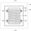
도 2는, 실시형태 1에 있어서의 차량에 장착한 상태에서의 수전부의 구조를 나타내는 사시도이다.
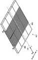
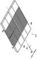
도 3은, 실시형태 1에 있어서의 차량에 장착한 상태에서의 코일 유닛 및 수전 코일의 구조를 나타내는 사시도이다.
도 4는, 실시형태 1에 있어서의 차량에 장착한 상태에서의 수전부와 자성 실드의 배치 관계를 나타내는 견상도(見上圖)이다.
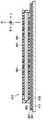
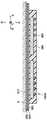
도 5는, 도 4 중의 Ⅴ-Ⅴ선 화살표에서 본 단면도이다.
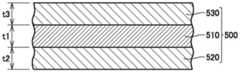
도 6은, 실시형태 1에 있어서의 자성 실드의 구조를 나타내는 단면도이다.
도 7은, 실시형태 1에 있어서의 자성 실드의 기능을 설명하는 단면 모식도이다.
도 8은, 배경기술에 있어서의 자성 실드의 기능을 설명하는 단면 모식도이다.
도 9는, 실시형태 1의 다른 형태에 있어서의 자성 실드의 구조를 나타내는 단면도이다.
도 10은, 실시형태 2에 있어서의 차량에 장착한 상태에서의 수전부와 자성 실드의 배치 관계를 나타내는 저면도(견상도)이다.
도 11은, 도 10 중의 ⅩⅠ-XI선 화살표에서 본 단면도이다.
도 12는, 실시형태 3에 있어서의 주차 영역에 탑재한 상태에서의 송전부를 나타내는 사시도이다.
도 13은, 실시형태 3에 있어서의 주차 영역에 탑재한 상태에서의 코일 유닛 및 송전 코일의 구조를 나타내는 사시도이다.
도 14는, 실시형태 3에 있어서의 주차 영역에 탑재한 상태에서의 송전부 및 자성 실드의 탑재 상태를 나타내는 단면도이다.
도 15는, 실시형태 4에 있어서의 주차 영역에 탑재한 상태에서의 송전부 및 자성 실드의 탑재 상태를 나타내는 단면도이다.
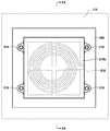
도 16은, 실시형태 5에 있어서의 차량에 장착한 상태에서의 수전부의 구조를 나타내는 도면이다.
도 17은, 실시형태 5에 있어서의 차량에 장착한 상태에서의 수전부와 자성 실드의 배치 관계를 나타내는 저면도(견상도)이다.
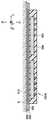
도 18은, 도 17 중의 XⅤⅢ-XⅤⅢ선 화살표에서 본 단면도이다.
도 19는, 실시형태 5에 있어서의 다른 자성 실드의 구조를 나타내는 평면도이다.
도 20은, 도 19 중의 XX-XX선 화살표에서 본 단면도이다.
도 21은, 실시형태 6에 있어서의 주차 영역에 탑재한 상태에서의 송전부의 구조를 나타내는 도면이다.
도 22는, 실시형태 6에 있어서의 주차 영역에 탑재한 상태에서의 송전부 및 자성 실드의 탑재 상태를 나타내는 단면도이다.
도 23은, 실시형태 6에 있어서의 다른 자성 실드의 구조를 나타내는 단면도이다.
도 24는, 각 실시형태에 있어서의 다른 자성 실드의 구조를 나타내는 단면도이다.1 is a diagram showing a power transmission system according to a first embodiment.
Fig. 2 is a perspective view showing a structure of a power receiver in a state of being mounted on a vehicle in the first embodiment. Fig.
Fig. 3 is a perspective view showing a structure of a coil unit and a power reception coil in a state of being mounted on a vehicle in the first embodiment. Fig.
Fig. 4 is a perspective view showing the arrangement relationship between the power receiver and the magnetic shield in the state of being mounted on the vehicle in the first embodiment. Fig.
5 is a sectional view taken along the line V-V in Fig.
6 is a cross-sectional view showing a structure of a magnetic shield according to the first embodiment.
7 is a schematic cross-sectional view for explaining the function of the magnetic shield in the first embodiment.
8 is a schematic cross-sectional view for explaining the function of the magnetic shield in the background art.
9 is a cross-sectional view showing a structure of a magnetic shield according to another embodiment of the first embodiment.
Fig. 10 is a bottom view (perspective view) showing the arrangement relationship between the power receiver and the magnetic shield in the state of being mounted on the vehicle in the second embodiment. Fig.
11 is a sectional view taken along the line XI-XI in Fig.
12 is a perspective view showing a power transmission unit in a state of being mounted on a parking area in the third embodiment;
13 is a perspective view showing a structure of a coil unit and a transmission coil in a state of being mounted on a parking area in the third embodiment.
Fig. 14 is a cross-sectional view showing a mounting state of a power transmitting portion and a magnetic shield in a state of being mounted on a parking area in Embodiment 3; Fig.
Fig. 15 is a cross-sectional view showing a mounting state of a power transmitting portion and a magnetic shield in a state of being mounted on a parking area in Embodiment 4. Fig.
16 is a view showing a structure of a power receiver in a state of being mounted on a vehicle in the fifth embodiment.
Fig. 17 is a bottom view (perspective view) showing the arrangement relationship between the power receiver and the magnetic shield in a state where the power receiver is mounted on the vehicle in the fifth embodiment. Fig.
18 is a sectional view taken along the line XVIII-XVIII line in Fig.
19 is a plan view showing the structure of another magnetic shield in the fifth embodiment.
20 is a sectional view taken along the line XX-XX in Fig.
Fig. 21 is a view showing a structure of a power transmitting unit in a state of being mounted on a parking area in the sixth embodiment. Fig.
22 is a cross-sectional view showing a mounting state of a power transmitting section and a magnetic shield in a state of being mounted on a parking area in the sixth embodiment.
23 is a cross-sectional view showing the structure of another magnetic shield in the sixth embodiment.
24 is a cross-sectional view showing the structure of another magnetic shield in each embodiment.
(실시형태 1 : 전력 전송 시스템(1000))(Embodiment 1: Power transmission system 1000)
도 1을 참조하여, 비접촉으로 전력을 전송하는 전력 전송 시스템(1000)에 대하여 설명한다. 전력 전송 시스템(1000)은 전동 차량(100) 및 외부 급전 장치(300)를 구비한다. 전동 차량(100)은 차량 본체(110) 및 수전 장치(200)를 포함한다. 차량 본체(110)는 차량 ECU(120), 정류기(130), DC/DC 컨버터(140), 배터리(150), 파워 컨트롤 유닛(160), 모터 유닛(170) 및 통신부(180) 등을 가진다.Referring to Fig. 1, a description will be given of a
수전 장치(200)는 수전부(210) 및 콘덴서(220)를 포함한다. 수전부(210)는, 예를 들면, 수전 코일(250) 및 코일 유닛(페라이트 코어)(260)을 포함한다. 수전 코일(250) 및 콘덴서(220)는 직렬 접속되나, 이들은 병렬 접속되어도 된다.The
수전 코일(250)의 감김수는, 수전 코일(250)과 송전 코일(450) 사이의 거리, 및 수전 코일(250)과 송전 코일(450)의 공명 강도를 나타내는 Q값(예를 들면 Q≥100) 및 그 결합도를 나타내는 결합 계수(κ) 등이 커지도록 적절히 설정된다. 수전 코일(250)은 정류기(130)에 접속된다. 정류기(130)는 수전 장치(200)로부터 공급되는 교류 전류를 직류 전류로 변환하여, DC/DC 컨버터(140)에 공급한다.The number of windings of the
외부 급전 장치(300)는 송전 장치(400), 고주파 전력 장치(310), 송전 ECU(320) 및 통신부(322)를 구비한다. 고주파 전력 장치(310)는 교류 전원(330) 및 송전 장치(400)에 접속된다. 송전 장치(400)는 송전부(410) 및 콘덴서(420)를 포함한다. 송전부(410)는, 예를 들면, 송전 코일(450) 및 코일 유닛(페라이트 코어)(460)을 포함한다. 송전 코일(450) 및 콘덴서(420)는 직렬 접속되나, 이들은 병렬 접속되어도 된다. 고주파 전력 장치(310)는, 교류 전원(330)으로부터 받는 전력을 고주파의 전력으로 변환하고, 변환한 고주파 전력을 송전 코일(450)에 공급한다. 송전 코일(450)은 수전부(210)의 수전 코일(250)에, 전자 유도에 의해 비접촉으로 전력을 송전한다.The external
(수전부(210)의 구조)(Structure of the receiver 210)
도 2 및 도 3을 참조하여, 수전부(210)의 구조를 설명한다. 도면 중에 있어서, 「D」는 연직방향 하방(D)을 나타낸다. 「L」은 차량 좌측방향(L)을 나타낸다. 「R」은 차량 우측방향(R)을 나타낸다. 「F」는 차량 전진방향(F)을 나타낸다. 「B」는 차량 후퇴방향(B)을 나타낸다. 「U」는 연직방향 상방(U)을 나타낸다. 이들에 대해서는 후술하는 각 도면에 있어서 공통된다.The structure of the
수전부(210)는 수전 코일(250) 및 코어 유닛(260)을 포함한다. 코어 유닛(260)에는, 차량의 전후방향(도면 중 화살표 BF방향)을 따라 연장되는 코일 권회축(수평 축선)(O1)을 중심으로 하여, 코어 유닛(260)의 상면 및 하면을 포함하는 주위에 있어서 나선 형상으로 수전 코일(250)이 권회되어 있다.The
코어 유닛(260)은 전체로서 판상의 형상을 가진다. 코어 유닛(260)은 복수의 분할 코어가 조합되고, 이 분할 코어가 절연지에 의해 포위되어 있다. 분할 코어에는 모두 페라이트가 이용된다. 또한, 분할 코어에 한정되지 않고 1매 구성의 페라이트여도 된다.The
수전 코일(250) 및 코어 유닛(260)은 수지(230)에 의해 밀봉되고, 수전부(210)는 전체로서는, 평판 형상의 입방체 형상을 가지고 있다. 수전부(210)의 측면에는, 수지에 의해 일체 성형된 장착 구멍을 가지는 장착용 플랜지(217)가 합계 4개소에 설치되고, 볼트(218)를 이용하여 차량 본체(110)의 바닥면에 위치하는 플로어 패널(114)에 고정된다.The
(수전부(210)의 고정)(Fixing of the receiver 210)
도 4 및 도 5를 참조하여, 수전부(210)의 플로어 패널(114)에 대한 고정 상태에 대하여 설명한다. 수전부(210)의 위에는 자성 실드(500)가 위치하고, 수전부(210)와 플로어 패널(114)의 사이에 자성 실드(500)가 끼워지도록 하여, 수전부(210) 및 자성 실드(500)가 플로어 패널(114)에 고정된다. 도 4에 나타내는 바와 같이, 자성 실드(500)의 크기는 평면적으로 보아 수전부(210)를 포함하는 크기이고, 수전부(210)의 전체가 자성 실드(500)에 대향하고 있다. 구체적으로는, 수전부(210)의 상면과 자성 실드(500)의 하면이 연직방향으로 대향하고 있다.The fixed state of the
(자성 실드(500)의 구조)(The structure of the magnetic shield 500)
도 5 내지 도 8을 참조하여, 자성 실드(500)의 구조 및 기능에 대하여 설명한다. 도 5 및 도 6을 참조하여, 자성 실드(500)는, 수전부(210)측에 위치하는 제 1 자성 시트(520)와, 이 제 1 자성 시트(520)를 사이에 두고 수전부(210)와는 반대측에 위치하는 금속 시트(510)와, 금속 시트(510)를 사이에 두고 제 1 자성 시트(520)와는 반대측(플로어 패널(114)측)에 위치하는 제 2 자성 시트(530)를 포함한다.The structure and function of the
즉, 금속 시트(510)가 제 1 자성 시트(520)와 제 2 자성 시트(530)에 의해 끼워져 있다. 제 1 자성 시트(520), 금속 시트(510) 및 제 2 자성 시트(530)의 평면적인 크기는 대략 동일하고, 가장자리부(전체 둘레)에 있어서, 제 1 자성 시트(520)와 제 2 자성 시트(530)가 고정되어 있다. 제 1 자성 시트(520) 및 제 2 자성 시트(530)의 평면적인 크기는, 수전부(210)의 평면 면적, 보다 구체적으로는 코어 유닛(260)의 평면 면적 이상이면 된다.That is, the
제 1 자성 시트(520)의 두께(t2) 및 제 2 자성 시트(530)의 두께(t3)는 0.5㎜∼2㎜ 정도이다. 제 1 자성 시트(520) 및 제 2 자성 시트(530)에는, 예를 들면, 자성재로서의 페라이트층과 절연층의 적층 구조로 이루어지는 시트재가 이용된다. 또한, 이 적층 구조에 한정되지 않고 자성 특성을 가지는 시트면 된다.The thickness t2 of the first
금속 시트(510)에 이용되는 금속으로는, 자속에 기인하는 발열이 적은 재료가 바람직하다. 예를 들면, 구리를 기재(基材)로 하는 시트가 이용되고, 기타가와공업주식회사제의 상품명 「레미레스(REMILESS/REMI)」를 이용할 수 있다. 「레미레스(REMILESS/REMI):등록상표」의 두께(t1)는 약 35㎛ 정도이다.As the metal used for the
또한, 상기 자성 실드(500)에 있어서는, 금속 시트(510)를 이용한 경우에 대하여 설명하고 있으나, 금속 시트에 한정되지 않고 도전성의 시트면 된다. 예를 들면, 그래파이트를 이용한 도전성 시트여도 된다. 이하에 나타내는 각 실시형태에 있어서도 동일하다.Although the
도 7을 참조하여, 자성 실드(500)는 상기한 제 1 자성 시트(520), 금속 시트(510) 및 제 2 자성 시트(530)의 3층 구조로 함으로써, 이하에 설명하는 기능을 가진다.7, the
수전부(210)로부터 튀어나온 자속(M1)의 대부분은, 제 1 자성 시트(520)의 내부로 들어간다. 그러나, 일부 자속(M2)은 제 1 자성 시트(520)를 튀어나와, 금속 시트(510)에 도달한다. 금속 시트(510)의 표면에 있어서는, 자속(M2)의 도달에 의해 와전류(S1)가 발생한다. 이 와전류(S1)에 기인하여 금속 시트(510)의 표면으로부터 새로운 전자계(M21)가 방사된다. 이 방사된 전자계(M21)는 제 2 자성 시트(530)의 내부로 들어가, 전자계(M21)의 외부로의 방출을 억제한다.Most of the magnetic flux M1 protruding from the
한편, 도 8에 나타내는 바와 같이, 배경기술에 있어서의 자성 실드(500Z)의 경우에는 제 2 자성 시트(530)가 설치되어 있지 않다. 그 결과, 와전류(S1)에 기인하여 금속 시트(510)의 표면에 발생한 전자계(M21)는 외부에 방사되게 된다.On the other hand, as shown in Fig. 8, in the case of the
이와 같이, 본 실시형태에 있어서의 자성 실드(500)를 이용한 경우에는, 제 2 자성 시트(530)를 설치함으로써, 금속 시트(510)의 표면에 발생한 전자계(M21)의 외부(플로어 패널(114)측)로의 누설을 억제하는 것을 가능하게 한다.In this way, when the
(다른 형태의 자성 실드의 구조)(Structure of other types of magnetic shields)
도 9에, 본 실시형태의 다른 형태에 있어서의 자성 실드의 단면 구조를 나타낸다. 수전부(210)측에 위치하는 제 1 자성 시트(520)는, 자속이 내부로 들어가는 점에서 자기(磁氣) 경로를 구성한다. 그 때문에, 제 1 자성 시트(520)는 자기 포화가 발생하지 않는 두께로 설계된다. 한편, 제 2 자성 시트(530)는 상기한 바와 같이, 금속 시트(510)의 표면에 발생한 전자계(M21)의 외부(플로어 패널(114))측으로의 누설을 억제하는 것이 목적이다. 따라서, 제 1 자성 시트(520)보다 두께를 얇게 해도 자기 포화가 발생하는 일은 없다. 따라서, 제 2 자성 시트(530)의 두께(t3)를 제 1 자성 시트(520)의 두께(t2)보다 얇게 설치해도 된다. 이로 인해, 제 2 자성 시트(530)에 필요한 비용의 삭감을 도모할 수 있다.Fig. 9 shows a sectional structure of a magnetic shield according to another embodiment of the present invention. The first
(실시형태 2)(Embodiment 2)
도 10 및 도 11을 참조하여, 본 실시형태의 자성 실드의 구조에 대하여 설명한다. 도 10은 수전부(210)와 자성 실드(500A)의 배치 관계를 나타내는 견상도, 도 11은 도 10 중의 XI-XI선 화살표에서 본 단면도이다.The structure of the magnetic shield of the present embodiment will be described with reference to Figs. 10 and 11. Fig. Fig. 10 is a perspective view showing the arrangement relationship of the
상술한 자성 실드(500)에 이용한 금속 시트(510)는 평면적으로 보아 수전부(210)의 전면(全面)을 포함하는 크기이다. 그러나, 본 실시형태에 있어서의 코어 유닛(260)에, 상기한 차량의 전후방향(도면 중 화살표 BF방향)을 따라 연장되는 코일 권회축(수평 축선)(O1)을 중심으로 하여 나선 형상으로 수전 코일(250)을 권회한 형식의 수전부(210)를 이용한 경우, 자속은 코일 권회축(수평 축선)(O1)을 따른 양단(兩端)부로부터 집중적으로 방사/입사된다.The
따라서, 자성 실드(500A)로서, 금속 시트(510)를 수전부(210)의 코일 권회축(수평 축선)(O1)을 따른 일단(一端)측에 배치되는 제 1 금속 시트(510A)와, 수전부(210)의 코일 권회축(수평 축선)(O1)을 따른 타단(他端)측에 배치되는 제 2 금속 시트(510B)의 2매 구성으로 하여, 부분적으로 자성 실드(500A)가 수전부(210)의 위에 위치하도록 해도 된다.Therefore, as the
이 경우에, 자속(M)은 코어 유닛(260)의 단면(端面)(261, 263)으로부터 출사(또는 입사)하는 점에서, 제 1 금속 시트(510A)는 평면적으로 보아 단면(261)을 포함하도록 배치하는 것이 바람직하고, 제 2 금속 시트(510B)도 평면적으로 보아 단면(263)을 포함하도록 배치하는 것이 바람직하다. 즉, 단면(261)으로부터 단면(263)에 걸쳐 연장되는 1매의 금속 시트를 채용한 경우와 비교하여, 금속 시트의 크기를 억제할 수 있다. 이로 인해, 금속 시트에 필요한 비용의 삭감을 도모할 수 있음과 함께, 금속 시트의 중량의 경감을 도모하는 것도 가능해진다.In this case, since the magnetic flux M exits (or enters) from the end faces 261 and 263 of the
또한, 도 10 및 도 11에 나타내는 예에 있어서, 수전부(210)의 중앙부(단면(261) 및 단면(263)의 사이에 위치하는 부분)로부터는 자속은 거의 외부에 방사되지 않는다. 그 때문에, 도 10 및 도 11에 나타내는 바와 같이, 수전부(210)의 중앙부에 금속 시트를 배치하지 않아도 외부에 방사되는 자속은 적다.10 and 11, the magnetic flux is hardly radiated to the outside from the central portion of the power receiver 210 (the portion located between the
수전부(210)의 중앙부로부터 방사되는 자속에 대해서도, 외부에 누설되는 것을 억제하기 위해, 전후방향으로 연장되는 금속 시트로서, 부분적으로 제 1 금속 시트(510A)와 제 2 금속 시트(510B)를 연결하도록 형성해도 된다.The
(실시형태 3)(Embodiment 3)
상기 실시형태는 수전부(210) 및 자성 실드(500)의 플로어 패널(114)에 대한 장착에 대하여 설명하였으나, 본 실시형태에서는, 외부 급전 장치(300)측에 있어서의, 송전부(410) 및 자성 실드(500)의 주차 영역(B)측에 대한 장착에 대하여, 도 12 내지 도 14를 참조하여 설명한다.The present embodiment has described the mounting of the
(송전부(410)의 구조)(Structure of the transmission unit 410)
도 12 및 도 13을 참조하여, 송전부(410)의 구조에 대하여 설명한다. 기본적 구조는 상기 수전부(210)과 동일하고, 송전부(410)는 송전 코일(450) 및 코어 유닛(460)을 포함한다. 코어 유닛(460)에는, 차량의 전후방향(도면 중 화살표 BF방향)을 따라 연장되는 코일 권회축(수평 축선)(O1)을 중심으로 하여, 코어 유닛(460)의 상면 및 하면을 포함하는 주위에 있어서 나선 형상으로 송전 코일(450)이 권회되어 있다. 코어 유닛(460)은 수전부(210)의 코어 유닛(260)과 동일하다.The structure of the
송전 코일(450) 및 코어 유닛(460)은 수지(430)에 의해 밀봉되고, 송전부(410)는 전체로서는, 평판 형상의 입방체 형상을 가지고 있다. 송전부(410)의 측면에는 수지에 의해 일체 성형된 장착 구멍을 가지는 장착용 플랜지(417)가 합계 4개소에 설치되고, 볼트(418)를 이용하여 주차 영역(B)에 고정된다.The
(송전부(410)의 고정)(Fixing of the transmission unit 410)
도 14를 참조하여, 송전부(410)의 주차 영역(B)에 대한 고정 상태에 대하여 설명한다. 송전부(410)의 하방에는 자성 실드(500)가 위치하고, 송전부(410)와 주차 영역(B)의 사이에 자성 실드(500)를 끼우도록 하여, 송전부(410) 및 자성 실드(500)가 주차 영역(B)에 고정된다. 자성 실드(500)의 크기는, 평면적으로 본 경우에는 송전부(410)를 포함하는 크기이다(도 4에 나타내는 수전부(210)의 경우와 동일).Referring to Fig. 14, the fixed state of the
자성 실드(500)의 구조 및 그 기능은 도 5 내지 도 8을 이용한 설명과 동일하기 때문에 여기에서는 생략한다.Since the structure and function of the
이와 같이, 본 실시형태에 있어서의 자성 실드(500)를 이용한 경우에 있어서도, 제 2 자성 시트(530)를 설치함으로써, 금속 시트(510)의 표면에 발생한 전자계(M21)의 외부(주차 영역(B))측으로의 누설을 억제하는 것을 가능하게 한다.In this way, even when the
(실시형태 4)(Fourth Embodiment)
도 15를 참조하여, 본 실시형태의 자성 실드의 구조에 대하여 설명한다. 상기한 실시형태 2에 나타낸, 부분적으로 자성 실드(500A)를 배치하는 경우와 마찬가지로, 금속 시트(510)를 송전부(410)의 코일 권회축(수평 축선)(O1)을 따른 일단측에 배치되는 제 1 금속 시트(510A)와, 송전부(410)의 코일 권회축(수평 축선)(O1)을 따른 타단측에 배치되는 제 2 금속 시트(510B)의 2매 구성으로 해도 된다.The structure of the magnetic shield of the present embodiment will be described with reference to Fig. The
이 경우에, 자속(M)은 코어 유닛(460)의 단면(端面)(461, 463)으로부터 출사(또는 입사)하는 점에서, 제 1 금속 시트(510A)는 평면적으로 보아 단면(461)을 포함하도록 배치하는 것이 바람직하고, 제 2 금속 시트(510B)도 평면적으로 보아 단면(463)을 포함하도록 배치하는 것이 바람직하다. 이로 인해, 금속 시트에 필요한 비용의 삭감을 도모할 수 있음과 함께, 금속 시트의 중량의 경감을 도모하는 것도 가능해진다.In this case, since the magnetic flux M exits (or enters) from the end faces 461 and 463 of the
또한, 도 15에서는, 완전히 분리된 제 1 금속 시트(510A) 및 제 2 금속 시트(510B)를 이용하고 있으나, 전후방향으로 연장되는 금속 시트에 의해, 부분적으로 제 1 금속 시트(510A)와 제 2 금속 시트(510B)가 연결되어 있어도 된다.Although the
(실시형태 5)(Embodiment 5)
상기 실시형태 1 및 2에 있어서의 수전부(210)에는, 코어 유닛에, 차량의 전후방향(도면 중 화살표 BF방향)을 따라 연장되는 코일 권회축(수평 축선)(O1)을 중심으로 하여 나선 형상으로 수전 코일(250)을 권회한 형식의 수전부(210)를 이용한 경우에 대하여 설명하였다. 본 실시형태에서는, 수전 코일(250)에, 연직방향으로 연장되는 연직 축선(O2)의 주위를 권회하는 소용돌이형의 수전 코일을 수전부(210U)에 이용한 경우에 대하여 설명한다.The
도 16 내지 도 18을 참조하여, 수전부(210U)의 구조를 설명한다. 수전부(210U)는 수전 코일(250) 및 코어 유닛(260)을 포함한다. 코어 유닛(260)의 자성 실드(500)와는 반대측의 면에는, 연직방향으로 연장되는 연직 축선(O2)의 주위를 권회하는 소용돌이형의 수전 코일(250)이 배치되어 있다.The structure of the
코어 유닛(260)은 전체로서 판상의 형상을 가진다. 코어 유닛(260)은 복수의 분할 코어가 조합되고, 이 분할 코어가 절연지에 의해 포위되어 있다. 분할 코어에는 모두 페라이트가 이용된다. 또한, 분할 코어에 한정되지 않고 1매 구성의 페라이트여도 된다.The
수전 코일(250) 및 코어 유닛(260)은 수지(230)에 의해 밀봉되고, 수전부(210U)는 전체로서는, 평판 형상의 입방체 형상을 가지고 있다. 수전부(210U)의 측면에는, 수지에 의해 일체 성형된 장착 구멍을 가지는 장착용 플랜지(217)가 합계 4개소에 설치되고, 볼트(218)를 이용하여 차량 본체(110)의 바닥면에 위치하는 플로어 패널(114)에 고정된다.The
(수전부(210U)의 고정)(Fixing of the
도 18을 참조하여, 수전부(210U)의 플로어 패널(114)에 대한 고정 상태에 대하여 설명한다. 수전부(210U)는, 수전부(210U)와 플로어 패널(114)의 사이에 자성 실드(500)를 끼우도록 하여, 플로어 패널(114)에 고정된다. 도 17에 나타내는 바와 같이, 자성 실드(500)의 크기는 평면적으로 보아 수전부(210U)를 포함하는 크기이다.The fixed state of the
자성 실드(500)의 구조 및 그 기능은 도 5 내지 도 8을 이용한 설명과 동일하기 때문에 여기에서는 생략한다.Since the structure and function of the
이와 같이, 본 실시형태에 있어서의 자성 실드(500)를 이용한 경우에는, 제 2 자성 시트(530)를 설치함으로써, 금속 시트(510)의 표면에 발생한 전자계(M21)의 외부(플로어 패널(114))측으로의 누설을 억제하는 것을 가능하게 한다.In this way, when the
(다른 형태의 자성 실드의 구조)(Structure of other types of magnetic shields)
도 19 및 도 20에, 본 실시형태의 다른 형태에 있어서의 자성 실드의 단면 구조를 나타낸다. 연직방향으로 연장되는 연직 축선(O2)의 주위를 권회하는 소용돌이형의 수전 코일(250)을 이용한 경우에는, 자속은 수전 코일(250)의 중심(연직 축선(O2))에 집중한다. 따라서, 평면적으로 본 경우에 금속 시트(510)의 크기를, 대략 수전부(210U)의 평면적인 크기까지 작게 해도 된다. 이로 인해, 금속 시트(510)에 필요한 비용의 삭감을 도모할 수 있음과 함께, 금속 시트의 중량의 경감을 도모하는 것도 가능해진다.19 and 20 show a cross-sectional structure of a magnetic shield according to another embodiment of the present embodiment. The magnetic flux concentrates on the center of the power reception coil 250 (vertical axis O2) when the vortex-type
(실시형태 6)(Embodiment 6)
상기 실시형태는 수전부(210U) 및 자성 실드(500)의 플로어 패널(114)에 대한 장착에 대하여 설명하였으나, 본 실시형태에서는, 외부 급전 장치(300)측에 있어서의, 송전부(410U) 및 자성 실드(500)의 주차 영역(B)측에 대한 장착에 대하여, 도 21 내지 도 23을 참조하여 설명한다.The present embodiment has described the mounting of the
(송전부(410U)의 구조)(Structure of
도 21 및 도 22를 참조하여, 송전부(410U)의 구조에 대하여 설명한다. 기본적 구조는 상기 수전부(210U)와 동일하고, 송전부(410U)는 송전 코일(450) 및 코어 유닛(460)을 포함한다. 코어 유닛(460)의 자성 실드(500)와는 반대측의 면에는, 연직방향으로 연장되는 연직 축선(O2)의 주위를 권회하는 소용돌이형의 송전 코일(450)이 배치되어 있다. 코어 유닛(460)은 수전부(210U)의 코어 유닛(260)과 동일하다.The structure of the
송전 코일(450) 및 코어 유닛(460)은 수지(430)에 의해 밀봉되고, 송전부(410)는 전체로서는, 도 12에 나타낸 송전부의 외관과 동일한 형상을 가져, 평판 형상의 입방체 형상을 가지고 있다. 송전부(410)의 측면에는, 수지에 의해 일체 성형된 장착 구멍을 가지는 장착용 플랜지(417)가 합계 4개소에 설치되고, 볼트(418)를 이용하여 주차 영역(B)에 고정된다.The
(송전부(410U)의 고정)(Fixing of the transmitting
도 22에 나타내는 바와 같이, 송전부(410U)의 고정은, 도 14에 나타낸 송전부(410)의 주차 영역(B)에 대한 고정 상태와 동일하고, 송전부(410U)는, 송전부(410U)와 주차 영역(B)의 사이에 자성 실드(500)를 끼우도록 하여, 주차 영역(B)에 고정된다. 자성 실드(500)의 크기는, 평면적으로 본 경우에는 송전부(410)를 포함하는 크기이다(도 4에 나타내는 수전부(210)의 경우와 동일).As shown in Fig. 22, the fixing of the
자성 실드(500)의 구조 및 그 기능은, 도 5 내지 도 8을 이용한 설명과 동일하기 때문에 여기에서는 생략한다.The structure and functions of the
이와 같이, 본 실시형태에 있어서의 자성 실드(500)를 이용한 경우에 있어서도, 제 2 자성 시트(530)를 설치함으로써, 금속 시트(510)의 표면에 발생한 전자계(M21)의 외부(주차 영역(B))측으로의 누설을 억제하는 것을 가능하게 한다.In this way, even when the
(다른 형태의 자성 실드의 구조)(Structure of other types of magnetic shields)
도 23에, 본 실시형태의 다른 형태에 있어서의 자성 실드의 단면 구조를 나타낸다. 도 19 및 도 20에 나타낸 금속 시트(510)와 마찬가지로, 자속은 수전 코일(250)의 중심(연직 축선(O2))에 집중하는 점에서, 평면적으로 본 경우에 금속 시트(510)의 크기를 대략 수전부(210U)의 평면적인 크기까지 작게 할 수 있다. 이로 인해, 금속 시트(510)에 필요한 비용의 삭감을 도모할 수 있음과 함께, 금속 시트의 중량의 경감을 도모하는 것도 가능해진다.23 shows a sectional structure of a magnetic shield according to another embodiment of the present embodiment. 19 and 20, the magnetic flux concentrates on the center (vertical axis O2) of the
이상과 같이 각 실시형태에 있어서의 구성에 의하면 자성 실드(500, 500A)의 구성을 채용함으로써, 제 1 자성 시트(520)를 튀어나온 자속에 의해, 금속 시트(510)의 표면에 와전류가 발생하고, 이 와전류에 기인하여 금속 시트(510)의 표면으로부터 전자계가 방사된 경우라도, 제 2 자성 시트(530)에 의해, 전자계의 외부로의 방출을 억제할 수 있다.As described above, according to the configuration of each embodiment, by adopting the configuration of the
또한, 상기 실시형태 1, 2, 5의 수전 장치측에 있어서는, 플로어 패널(114)의 하면에 자성 실드(500)가 접하고, 자성 실드(500)의 하면에 수전부(210, 210U)가 접하도록 하여, 수전부(210, 210U) 및 자성 실드(500)가 플로어 패널(114)에 고정되어 있으나, 플로어 패널(114)과 자성 실드(500)의 사이에 간극이 있어도 된다. 또한, 자성 실드(500)와 수전부(210, 210U)의 사이에 간극이 있어도 된다.The
또한, 코일 권회축(수평 축선)(O1)을 차량의 전후방향을 따르도록 배치하고 있으나, 수평으로 배치되어 있으면 되고, 좌우방향을 따르도록 배치해도 된다.Further, although the coil winding axis (horizontal axis) O1 is disposed along the front-rear direction of the vehicle, the coil winding axis (horizontal axis) O1 may be arranged horizontally or may be arranged along the lateral direction.
또한, 플로어 패널(114)의 형상은 도시하는 형상에 한정되지 않는다. 예를 들면, 배기관을 통과시키기 위한 터널을 가지는 형상의 플로어 패널의 경우여도 된다.Further, the shape of the
상기 실시형태 3, 4, 6의 송전 장치측에 있어서도, 주차 영역(B)의 상면에 자성 실드(500, 500A)가 접하고, 자성 실드(500, 500A)의 상면에 송전부(410, 410U)가 접하도록 하여, 송전부(410, 410U) 및 자성 실드(500, 500A)가 주차 영역(B)에 고정되어 있으나, 주차 영역(B)과 자성 실드(500)의 사이에 간극이 있어도 된다. 또한, 자성 실드(500)와 송전부(410, 410U)의 사이에 간극이 있어도 된다.The
또한, 평탄한 주차 영역(B)의 위에 자성 실드(500) 및 송전부(410)를 탑재한 경우를 나타내고 있으나, 주차 영역(B)에 오목부를 설치하고, 이 오목부의 안에 자성 실드(500) 및 송전부(410)를 매립하여, 주차 영역(B)의 표면을 평탄하게 마무리해도 된다.Although the case where the
또한, 상기 실시형태 1 내지 4에 있어서, 코일 권회축(수평 축선)(O1)을 차량의 전후방향을 따르도록 배치하고 있으나, 수평으로 배치되어 있으면 되고, 차량의 좌우방향을 따르도록 배치해도 된다.In the first to fourth embodiments, the coil winding axis (horizontal axis) O1 is disposed along the front-rear direction of the vehicle, but may be arranged horizontally or may be disposed along the lateral direction of the vehicle .
또한, 상기 각 실시형태에 있어서, 상기한 자성 실드(500, 500A)의 3층 구조에 있어서, 추가로 제 2 자성 시트(530)로부터의 자속의 누설이 문제가 되는 경우에는, 제 2 자성 시트(530)의 위에 금속 시트 및 자성 시트를 설치하도록 하면 된다.In the three-layer structure of the
따라서, 자성 시트, 금속 시트 및 자성 시트의 3층 구조에 한정되는 것은 아니고, 도 24에 나타내는 바와 같이, 자성 실드(500B)로서, 제 1 자성 시트(520), 금속 시트(510), 제 2 자성 시트(530)의 위에, 추가로, 금속 시트(510), 제 2 자성 시트(530)를 설치해도 된다. 따라서, 자성 실드로서는, 적어도 자성 시트에 끼워진 도전층을 1층 이상 가지는 시트면 된다.Therefore, the present invention is not limited to the three-layer structure of the magnetic sheet, the metal sheet and the magnetic sheet, but may be applied to the first
또한, 상기 각 실시형태에 있어서, 수전부, 송전부, 자성 실드의 형상은 상기 직사각형에 한정되지 않고, 코일의 형상에 맞추어 원형 등 적절히 형상을 변경하는 것이 가능하다.In each of the above-described embodiments, the shape of the power receiver, the power transmitting portion, and the magnetic shield is not limited to the rectangular shape, but can be appropriately changed in shape such as a circle in conformity with the shape of the coil.
상기 각 실시형태에 대하여 도면을 참조하면서 설명하였으나, 개수 및 양 등을 언급하는 경우, 특별히 기재가 있는 경우를 제외하고, 본 발명의 범위는 반드시 그 개수 및 양 등에 한정되지는 않는다. 동일한 부품 및 상당 부품에는 동일한 참조 번호를 부여하고, 중복되는 설명은 반복하지 않은 경우가 있다. 또한, 각 실시형태를 적절히 조합하여 이용하는 것은 당초부터 예정되어 있다.While the present invention has been particularly shown and described with reference to exemplary embodiments thereof, it is to be understood that the invention is not limited to the disclosed exemplary embodiments. The same parts and equivalent parts are given the same reference numerals, and redundant descriptions may not be repeated. It is originally planned to use the embodiments in appropriate combination.
본 발명의 실시형태에 대하여 설명하였으나, 금번에 개시된 실시형태는 모든 점에서 예시이며 제한적인 것이 아니라고 생각되어야 한다. 본 발명의 범위는 청구범위에 의해 나타내지고, 청구범위와 균등한 의미 및 범위 내에서의 모든 변경이 포함되는 것이 의도된다.Although the embodiments of the present invention have been described, it should be understood that the embodiments disclosed herein are illustrative and non-restrictive in all respects. It is intended that the scope of the invention be represented by the claims and that all changes that come within the meaning and range of equivalency of the claims are intended to be embraced therein.
Claims (9)
Translated fromKorean상기 수전부를 사이에 두고 상기 송전부가 위치하는 측과는 반대측에 위치하고, 적어도 일부가 상기 수전부에 대향하는 자성 실드를 구비하며,
상기 자성 실드는,
상기 수전부측에 위치하는 제 1 자성 시트와,
상기 제 1 자성 시트를 사이에 두고 상기 수전부와는 반대측에 위치하는 도전성 시트와,
상기 도전성 시트를 사이에 두고 상기 제 1 자성 시트와는 반대측에 위치하는 제 2 자성 시트를 포함하는 수전 장치.A power receiver for receiving power from the power transmitting part in a noncontact manner,
And a magnetic shield which is located on the side opposite to the side where the power transmission portion is located with the power receiver interposed therebetween and at least a part of which is opposed to the power receiver,
The magnetic shield may comprise:
A first magnetic sheet positioned on the power receiver side,
A conductive sheet positioned on the side opposite to the power receiver with the first magnetic sheet interposed therebetween,
And a second magnetic sheet positioned on the opposite side of the first magnetic sheet with the conductive sheet interposed therebetween.
상기 수전부는, 수평방향으로 연장되는 수평 축선의 주위를 권회하는 수전 코일을 포함하고,
상기 도전성 시트는,
상기 수전부의 상기 수평 축선을 따른 일단측에 배치되는 제 1 도전성 시트와,
상기 수전부의 상기 수평 축선을 따른 타단측에 배치되는 제 2 도전성 시트를 가지는 수전 장치.The method according to claim 1,
Wherein the power receiver includes a power reception coil wound around a horizontal axis extending in a horizontal direction,
In the conductive sheet,
A first conductive sheet disposed on one end side of the power receiver along the horizontal axis,
And a second conductive sheet disposed on the other end side of the power receiver along the horizontal axis.
상기 제 2 자성 시트는, 상기 제 1 자성 시트의 두께보다 얇게 설치되어 있는, 수전 장치.3. The method according to claim 1 or 2,
Wherein the second magnetic sheet is provided so as to be thinner than the thickness of the first magnetic sheet.
상기 수전부는, 연직방향으로 연장되는 연직 축선의 주위를 권회하는 수전 코일을 포함하고,
상기 도전성 시트는, 상기 축선이 통과하는 위치를 포함하도록 배치되어 있는, 수전 장치.The method according to claim 1,
Wherein the power receiver includes a power reception coil for winding around a vertical axis extending in a vertical direction,
Wherein the conductive sheet is arranged to include a position through which the axis passes.
플로어 패널을 가지는 차량 본체를 구비하고,
상기 자성 실드는, 상기 수전부와 상기 플로어 패널의 사이에 배치되어 있는, 차량.The water receiving apparatus according to claim 1,
A vehicle body having a floor panel,
Wherein the magnetic shield is disposed between the power receiver and the floor panel.
상기 송전부를 사이에 두고 상기 송전부가 위치하는 측과는 반대측에 위치하고, 적어도 일부가 상기 송전부에 대향하는 자성 실드를 구비하며,
상기 자성 실드는,
상기 송전부측에 위치하는 제 1 자성 시트와,
상기 제 1 자성 시트를 사이에 두고 상기 송전부와는 반대측에 위치하는 도전성 시트와,
상기 도전성 시트를 사이에 두고 상기 제 1 자성 시트와는 반대측에 위치하는 제 2 자성 시트를 포함하는 송전 장치.A transmission unit for transmitting power to the receiver in a non-contact manner,
And a magnetic shield which is located on the side opposite to the side where the power transmission portion is located with the power transmission portion interposed therebetween and at least a part of which is opposed to the power transmission portion,
The magnetic shield may comprise:
A first magnetic sheet positioned on the power transmission unit side,
A conductive sheet disposed on the side opposite to the power transmitting portion with the first magnetic sheet interposed therebetween,
And a second magnetic sheet positioned on the opposite side of the first magnetic sheet with the conductive sheet interposed therebetween.
상기 송전부는, 수평방향으로 연장되는 수평 축선의 주위를 권회하는 송전 코일을 포함하고,
상기 도전성 시트는,
상기 송전부의 상기 수평 축선을 따른 일단측에 배치되는 제 1 도전성 시트와,
상기 송전부의 상기 수평 축선을 따른 타단측에 배치되는 제 2 도전성 시트를 가지는 송전 장치.The method according to claim 6,
Wherein the power transmission portion includes a power transmission coil for winding around a horizontal axis extending in a horizontal direction,
In the conductive sheet,
A first conductive sheet disposed on one end side of the power transmission unit along the horizontal axis,
And a second conductive sheet disposed on the other end side of the power transmission unit along the horizontal axis.
상기 제 2 자성 시트는, 상기 제 1 자성 시트의 두께보다 얇게 설치되어 있는, 송전 장치.8. The method according to claim 6 or 7,
Wherein the second magnetic sheet is provided so as to be thinner than the thickness of the first magnetic sheet.
상기 송전부는, 연직방향으로 연장되는 연직 축선의 주위를 권회하는 송전 코일을 포함하고,
상기 도전성 시트는, 상기 축선이 통과하는 위치를 포함하도록 배치되어 있는, 송전 장치.The method according to claim 6,
Wherein the power transmission portion includes a power transmission coil for winding around a vertical axis extending in a vertical direction,
Wherein the conductive sheet is disposed so as to include a position through which the axis passes.
Applications Claiming Priority (2)
| Application Number | Priority Date | Filing Date | Title |
|---|---|---|---|
| JP2014059719AJP6060330B2 (en) | 2014-03-24 | 2014-03-24 | Power receiving device, vehicle, and power transmitting device |
| JPJP-P-2014-059719 | 2014-03-24 |
Publications (2)
| Publication Number | Publication Date |
|---|---|
| KR20150110397Atrue KR20150110397A (en) | 2015-10-02 |
| KR101711532B1 KR101711532B1 (en) | 2017-03-02 |
Family
ID=52727007
Family Applications (1)
| Application Number | Title | Priority Date | Filing Date |
|---|---|---|---|
| KR1020150038941AActiveKR101711532B1 (en) | 2014-03-24 | 2015-03-20 | Power receiving device, vehicle, and power transmission device |
Country Status (5)
| Country | Link |
|---|---|
| US (1) | US9876364B2 (en) |
| EP (1) | EP2927917B1 (en) |
| JP (1) | JP6060330B2 (en) |
| KR (1) | KR101711532B1 (en) |
| CN (1) | CN104953717B (en) |
Families Citing this family (11)
| Publication number | Priority date | Publication date | Assignee | Title |
|---|---|---|---|---|
| JP6160083B2 (en)* | 2013-01-08 | 2017-07-12 | 株式会社Ihi | Foreign object detection device |
| EP3307815A4 (en) | 2015-06-12 | 2019-02-20 | NeoGraf Solutions, LLC | GRAPHITE COMPOSITE MATERIALS AND THERMAL MANAGEMENT SYSTEMS |
| US10181757B2 (en)* | 2015-09-17 | 2019-01-15 | Qualcomm Incorporated | Apparatus and methods for shielding a wireless power transmitter |
| JP6743432B2 (en) | 2016-03-14 | 2020-08-19 | 株式会社Ihi | Coil device |
| WO2017172939A1 (en)* | 2016-03-31 | 2017-10-05 | Advanced Energy Technologies Llc | Noise suppressing assemblies |
| JP6519541B2 (en)* | 2016-07-01 | 2019-05-29 | トヨタ自動車株式会社 | Coil unit |
| DE102016218692A1 (en) | 2016-09-28 | 2018-03-29 | Bayerische Motoren Werke Aktiengesellschaft | Safety system for a pressure vessel of a motor vehicle |
| JP6881083B2 (en)* | 2017-06-26 | 2021-06-02 | 株式会社Ihi | Coil device |
| JP7003651B2 (en)* | 2017-12-27 | 2022-01-20 | トヨタ自動車株式会社 | vehicle |
| ES2739876B2 (en)* | 2018-08-01 | 2020-07-15 | Fundacion Circe Centro De Investig De Recursos Y Consumos Energeticos | INDUCTIVE COUPLING DEVICE AND ELECTRONIC TRANSFORMER THAT MAKES USE OF THE SAME |
| JP2020061517A (en)* | 2018-10-12 | 2020-04-16 | トヨタ自動車株式会社 | Coil unit |
Citations (1)
| Publication number | Priority date | Publication date | Assignee | Title |
|---|---|---|---|---|
| JP2009076513A (en)* | 2007-09-19 | 2009-04-09 | Yoshi Takaishi | Shield structure for planar coil |
Family Cites Families (29)
| Publication number | Priority date | Publication date | Assignee | Title |
|---|---|---|---|---|
| JPS63305599A (en)* | 1987-06-05 | 1988-12-13 | Riken Corp | Electromagnetic shield material |
| DE4029498A1 (en)* | 1990-09-18 | 1992-03-19 | Vacuumschmelze Gmbh | SHIELDING CABIN WITH SUPPORTING SANDWICH STRUCTURE |
| EP0751497A1 (en)* | 1995-06-29 | 1997-01-02 | Mitsumi Electric Company Ltd. | Magnetic head |
| JP2000348916A (en)* | 1999-06-04 | 2000-12-15 | Tokin Corp | Manufacture of magnetic sheet |
| JP3475132B2 (en)* | 1999-09-22 | 2003-12-08 | 三洋電機株式会社 | Driving device with magnetic shielding structure and linear motor |
| US7825543B2 (en) | 2005-07-12 | 2010-11-02 | Massachusetts Institute Of Technology | Wireless energy transfer |
| CN101860089B (en) | 2005-07-12 | 2013-02-06 | 麻省理工学院 | wireless non-radiative energy transfer |
| JP2007059456A (en)* | 2005-08-22 | 2007-03-08 | Em Techno:Kk | Radio wave absorber |
| US7795708B2 (en)* | 2006-06-02 | 2010-09-14 | Honeywell International Inc. | Multilayer structures for magnetic shielding |
| KR20110117732A (en) | 2007-03-27 | 2011-10-27 | 메사추세츠 인스티튜트 오브 테크놀로지 | Wireless energy transfer |
| JP5104024B2 (en)* | 2007-05-16 | 2012-12-19 | 横河電機株式会社 | Magnetic shield device |
| US8466654B2 (en)* | 2008-07-08 | 2013-06-18 | Qualcomm Incorporated | Wireless high power transfer under regulatory constraints |
| JP2011035159A (en)* | 2009-07-31 | 2011-02-17 | Tokyo Electric Power Co Inc:The | Stationary induction appliance |
| JP5746049B2 (en)* | 2009-12-17 | 2015-07-08 | トヨタ自動車株式会社 | Power receiving device and power transmitting device |
| WO2011084936A2 (en) | 2010-01-05 | 2011-07-14 | Access Business Group International Llc | Inductive charging system for electric vehicle |
| JP2013523066A (en)* | 2010-03-10 | 2013-06-13 | ウィトリシティ コーポレーション | Wireless energy transfer converter |
| WO2011112795A1 (en)* | 2010-03-10 | 2011-09-15 | Witricity Corporation | Wireless energy transfer converters |
| JP2012038807A (en)* | 2010-08-04 | 2012-02-23 | Toshiba Corp | Electromagnetic shield sheet |
| JP5581163B2 (en) | 2010-09-30 | 2014-08-27 | 日東電工株式会社 | EMI shielding sheet for wireless power transmission |
| EP3196903B1 (en)* | 2011-01-19 | 2019-05-08 | Technova Inc. | Contactless power transfer apparatus |
| US20140111021A1 (en) | 2011-06-30 | 2014-04-24 | Toyota Jidosha Kabushiki Kaisha | Power transmission device, power reception device and power transfer system |
| JP5772535B2 (en) | 2011-11-18 | 2015-09-02 | トヨタ自動車株式会社 | Power transmission system and vehicle |
| JP5668676B2 (en) | 2011-12-15 | 2015-02-12 | トヨタ自動車株式会社 | Power receiving device, vehicle including the same, power transmitting device, and power transmission system |
| DE102011056807A1 (en) | 2011-12-21 | 2013-06-27 | Thyssenkrupp Electrical Steel Gmbh | Magnetic field shield for electromagnetic fields and vehicle with integrated magnetic field shielding |
| JP2013132171A (en) | 2011-12-22 | 2013-07-04 | Toyota Motor Corp | Power transmitter, power receiver, and power transmission system |
| JP5718830B2 (en) | 2012-01-16 | 2015-05-13 | トヨタ自動車株式会社 | vehicle |
| JP5825108B2 (en) | 2012-01-16 | 2015-12-02 | トヨタ自動車株式会社 | Power receiving device and power transmitting device |
| JP5810944B2 (en)* | 2012-01-31 | 2015-11-11 | トヨタ自動車株式会社 | Vehicle and power transmission system |
| JP6086189B2 (en)* | 2012-09-05 | 2017-03-01 | Tdk株式会社 | Coil device |
- 2014
- 2014-03-24JPJP2014059719Apatent/JP6060330B2/enactiveActive
- 2015
- 2015-03-13USUS14/657,999patent/US9876364B2/enactiveActive
- 2015-03-20KRKR1020150038941Apatent/KR101711532B1/enactiveActive
- 2015-03-23CNCN201510126460.3Apatent/CN104953717B/enactiveActive
- 2015-03-23EPEP15160242.2Apatent/EP2927917B1/enactiveActive
Patent Citations (1)
| Publication number | Priority date | Publication date | Assignee | Title |
|---|---|---|---|---|
| JP2009076513A (en)* | 2007-09-19 | 2009-04-09 | Yoshi Takaishi | Shield structure for planar coil |
Also Published As
| Publication number | Publication date |
|---|---|
| CN104953717B (en) | 2018-09-21 |
| EP2927917A2 (en) | 2015-10-07 |
| CN104953717A (en) | 2015-09-30 |
| US20150270717A1 (en) | 2015-09-24 |
| EP2927917A3 (en) | 2015-10-14 |
| US9876364B2 (en) | 2018-01-23 |
| EP2927917B1 (en) | 2020-05-06 |
| JP2015185643A (en) | 2015-10-22 |
| JP6060330B2 (en) | 2017-01-18 |
| KR101711532B1 (en) | 2017-03-02 |
Similar Documents
| Publication | Publication Date | Title |
|---|---|---|
| KR101711532B1 (en) | Power receiving device, vehicle, and power transmission device | |
| JP4209437B2 (en) | Non-contact power feeding device for mobile body and protection device therefor | |
| US11264834B2 (en) | Coil apparatus | |
| JP6164421B2 (en) | Power transmission coil unit and wireless power transmission device | |
| US10250071B2 (en) | Wireless power supply coil | |
| JP6217518B2 (en) | Wireless power supply system and wireless power transmission system | |
| US10308124B2 (en) | Power reception apparatus and power transmission apparatus | |
| US10199163B2 (en) | Ground-side coil unit | |
| WO2015146889A1 (en) | Power reception system | |
| JP2018085808A (en) | Coil unit | |
| CN104426249B (en) | Power receiving device, power transmitting device, and vehicle | |
| US9884563B2 (en) | Power receiving device and power transmitting device | |
| US10014106B2 (en) | Coil for non-contact power transmission system and non-contact power transmission system | |
| JP2016129164A (en) | Power receiving device and power transmitting device | |
| JP6111645B2 (en) | Coil device and wireless power transmission system using the same | |
| JP2015106938A (en) | Power transmission coil unit and wireless power transmission device | |
| JP6217435B2 (en) | Power receiving device | |
| JP6162609B2 (en) | Non-contact power feeding device | |
| JP2017212302A (en) | Coil device, non-contact power supply device and non-contact power reception device | |
| JP2016105435A (en) | Power reception device and power transmission device | |
| JP6532086B2 (en) | Externally shielded non-contact power supply | |
| JP2025155573A (en) | Wireless power transmitting device, wireless power receiving device, and wireless power supply system | |
| JP2015106580A (en) | Power transmission coil unit and wireless power transmission device |
Legal Events
| Date | Code | Title | Description |
|---|---|---|---|
| A201 | Request for examination | ||
| PA0109 | Patent application | Patent event code:PA01091R01D Comment text:Patent Application Patent event date:20150320 | |
| PA0201 | Request for examination | ||
| PG1501 | Laying open of application | ||
| E902 | Notification of reason for refusal | ||
| PE0902 | Notice of grounds for rejection | Comment text:Notification of reason for refusal Patent event date:20160715 Patent event code:PE09021S01D | |
| E701 | Decision to grant or registration of patent right | ||
| PE0701 | Decision of registration | Patent event code:PE07011S01D Comment text:Decision to Grant Registration Patent event date:20170126 | |
| GRNT | Written decision to grant | ||
| PR0701 | Registration of establishment | Comment text:Registration of Establishment Patent event date:20170223 Patent event code:PR07011E01D | |
| PR1002 | Payment of registration fee | Payment date:20170224 End annual number:3 Start annual number:1 | |
| PG1601 | Publication of registration | ||
| FPAY | Annual fee payment | Payment date:20200205 Year of fee payment:4 | |
| PR1001 | Payment of annual fee | Payment date:20200205 Start annual number:4 End annual number:4 | |
| PR1001 | Payment of annual fee | Payment date:20210128 Start annual number:5 End annual number:5 | |
| PR1001 | Payment of annual fee | Payment date:20220120 Start annual number:6 End annual number:6 | |
| PR1001 | Payment of annual fee | Payment date:20240117 Start annual number:8 End annual number:8 | |
| PR1001 | Payment of annual fee | Payment date:20250106 Start annual number:9 End annual number:9 |