KR20150100731A - A bone graft distribution system - Google Patents
A bone graft distribution systemDownload PDFInfo
- Publication number
- KR20150100731A KR20150100731AKR1020157018814AKR20157018814AKR20150100731AKR 20150100731 AKR20150100731 AKR 20150100731AKR 1020157018814 AKR1020157018814 AKR 1020157018814AKR 20157018814 AKR20157018814 AKR 20157018814AKR 20150100731 AKR20150100731 AKR 20150100731A
- Authority
- KR
- South Korea
- Prior art keywords
- proximal
- distal
- frame
- connector elements
- struts
- Prior art date
- Legal status (The legal status is an assumption and is not a legal conclusion. Google has not performed a legal analysis and makes no representation as to the accuracy of the status listed.)
- Granted
Links
Images


Classifications
- A—HUMAN NECESSITIES
- A61—MEDICAL OR VETERINARY SCIENCE; HYGIENE
- A61F—FILTERS IMPLANTABLE INTO BLOOD VESSELS; PROSTHESES; DEVICES PROVIDING PATENCY TO, OR PREVENTING COLLAPSING OF, TUBULAR STRUCTURES OF THE BODY, e.g. STENTS; ORTHOPAEDIC, NURSING OR CONTRACEPTIVE DEVICES; FOMENTATION; TREATMENT OR PROTECTION OF EYES OR EARS; BANDAGES, DRESSINGS OR ABSORBENT PADS; FIRST-AID KITS
- A61F2/00—Filters implantable into blood vessels; Prostheses, i.e. artificial substitutes or replacements for parts of the body; Appliances for connecting them with the body; Devices providing patency to, or preventing collapsing of, tubular structures of the body, e.g. stents
- A61F2/02—Prostheses implantable into the body
- A61F2/30—Joints
- A61F2/44—Joints for the spine, e.g. vertebrae, spinal discs
- A61F2/4455—Joints for the spine, e.g. vertebrae, spinal discs for the fusion of spinal bodies, e.g. intervertebral fusion of adjacent spinal bodies, e.g. fusion cages
- A61F2/447—Joints for the spine, e.g. vertebrae, spinal discs for the fusion of spinal bodies, e.g. intervertebral fusion of adjacent spinal bodies, e.g. fusion cages substantially parallelepipedal, e.g. having a rectangular or trapezoidal cross-section
- A—HUMAN NECESSITIES
- A61—MEDICAL OR VETERINARY SCIENCE; HYGIENE
- A61F—FILTERS IMPLANTABLE INTO BLOOD VESSELS; PROSTHESES; DEVICES PROVIDING PATENCY TO, OR PREVENTING COLLAPSING OF, TUBULAR STRUCTURES OF THE BODY, e.g. STENTS; ORTHOPAEDIC, NURSING OR CONTRACEPTIVE DEVICES; FOMENTATION; TREATMENT OR PROTECTION OF EYES OR EARS; BANDAGES, DRESSINGS OR ABSORBENT PADS; FIRST-AID KITS
- A61F2/00—Filters implantable into blood vessels; Prostheses, i.e. artificial substitutes or replacements for parts of the body; Appliances for connecting them with the body; Devices providing patency to, or preventing collapsing of, tubular structures of the body, e.g. stents
- A61F2/02—Prostheses implantable into the body
- A61F2/30—Joints
- A61F2/44—Joints for the spine, e.g. vertebrae, spinal discs
- A61F2/442—Intervertebral or spinal discs, e.g. resilient
- A—HUMAN NECESSITIES
- A61—MEDICAL OR VETERINARY SCIENCE; HYGIENE
- A61F—FILTERS IMPLANTABLE INTO BLOOD VESSELS; PROSTHESES; DEVICES PROVIDING PATENCY TO, OR PREVENTING COLLAPSING OF, TUBULAR STRUCTURES OF THE BODY, e.g. STENTS; ORTHOPAEDIC, NURSING OR CONTRACEPTIVE DEVICES; FOMENTATION; TREATMENT OR PROTECTION OF EYES OR EARS; BANDAGES, DRESSINGS OR ABSORBENT PADS; FIRST-AID KITS
- A61F2/00—Filters implantable into blood vessels; Prostheses, i.e. artificial substitutes or replacements for parts of the body; Appliances for connecting them with the body; Devices providing patency to, or preventing collapsing of, tubular structures of the body, e.g. stents
- A61F2/02—Prostheses implantable into the body
- A61F2/30—Joints
- A61F2/46—Special tools for implanting artificial joints
- A61F2/4603—Special tools for implanting artificial joints for insertion or extraction of endoprosthetic joints or of accessories thereof
- A61F2/4611—Special tools for implanting artificial joints for insertion or extraction of endoprosthetic joints or of accessories thereof of spinal prostheses
- A—HUMAN NECESSITIES
- A61—MEDICAL OR VETERINARY SCIENCE; HYGIENE
- A61F—FILTERS IMPLANTABLE INTO BLOOD VESSELS; PROSTHESES; DEVICES PROVIDING PATENCY TO, OR PREVENTING COLLAPSING OF, TUBULAR STRUCTURES OF THE BODY, e.g. STENTS; ORTHOPAEDIC, NURSING OR CONTRACEPTIVE DEVICES; FOMENTATION; TREATMENT OR PROTECTION OF EYES OR EARS; BANDAGES, DRESSINGS OR ABSORBENT PADS; FIRST-AID KITS
- A61F2/00—Filters implantable into blood vessels; Prostheses, i.e. artificial substitutes or replacements for parts of the body; Appliances for connecting them with the body; Devices providing patency to, or preventing collapsing of, tubular structures of the body, e.g. stents
- A61F2/02—Prostheses implantable into the body
- A61F2/30—Joints
- A61F2/3094—Designing or manufacturing processes
- A61F2/30965—Reinforcing the prosthesis by embedding particles or fibres during moulding or dipping
- A—HUMAN NECESSITIES
- A61—MEDICAL OR VETERINARY SCIENCE; HYGIENE
- A61F—FILTERS IMPLANTABLE INTO BLOOD VESSELS; PROSTHESES; DEVICES PROVIDING PATENCY TO, OR PREVENTING COLLAPSING OF, TUBULAR STRUCTURES OF THE BODY, e.g. STENTS; ORTHOPAEDIC, NURSING OR CONTRACEPTIVE DEVICES; FOMENTATION; TREATMENT OR PROTECTION OF EYES OR EARS; BANDAGES, DRESSINGS OR ABSORBENT PADS; FIRST-AID KITS
- A61F2/00—Filters implantable into blood vessels; Prostheses, i.e. artificial substitutes or replacements for parts of the body; Appliances for connecting them with the body; Devices providing patency to, or preventing collapsing of, tubular structures of the body, e.g. stents
- A61F2/02—Prostheses implantable into the body
- A61F2/30—Joints
- A61F2/44—Joints for the spine, e.g. vertebrae, spinal discs
- A61F2/441—Joints for the spine, e.g. vertebrae, spinal discs made of inflatable pockets or chambers filled with fluid, e.g. with hydrogel
- A—HUMAN NECESSITIES
- A61—MEDICAL OR VETERINARY SCIENCE; HYGIENE
- A61F—FILTERS IMPLANTABLE INTO BLOOD VESSELS; PROSTHESES; DEVICES PROVIDING PATENCY TO, OR PREVENTING COLLAPSING OF, TUBULAR STRUCTURES OF THE BODY, e.g. STENTS; ORTHOPAEDIC, NURSING OR CONTRACEPTIVE DEVICES; FOMENTATION; TREATMENT OR PROTECTION OF EYES OR EARS; BANDAGES, DRESSINGS OR ABSORBENT PADS; FIRST-AID KITS
- A61F2/00—Filters implantable into blood vessels; Prostheses, i.e. artificial substitutes or replacements for parts of the body; Appliances for connecting them with the body; Devices providing patency to, or preventing collapsing of, tubular structures of the body, e.g. stents
- A61F2/02—Prostheses implantable into the body
- A61F2/30—Joints
- A61F2/46—Special tools for implanting artificial joints
- A61F2/4684—Trial or dummy prostheses
- A—HUMAN NECESSITIES
- A61—MEDICAL OR VETERINARY SCIENCE; HYGIENE
- A61F—FILTERS IMPLANTABLE INTO BLOOD VESSELS; PROSTHESES; DEVICES PROVIDING PATENCY TO, OR PREVENTING COLLAPSING OF, TUBULAR STRUCTURES OF THE BODY, e.g. STENTS; ORTHOPAEDIC, NURSING OR CONTRACEPTIVE DEVICES; FOMENTATION; TREATMENT OR PROTECTION OF EYES OR EARS; BANDAGES, DRESSINGS OR ABSORBENT PADS; FIRST-AID KITS
- A61F2/00—Filters implantable into blood vessels; Prostheses, i.e. artificial substitutes or replacements for parts of the body; Appliances for connecting them with the body; Devices providing patency to, or preventing collapsing of, tubular structures of the body, e.g. stents
- A61F2/02—Prostheses implantable into the body
- A61F2/28—Bones
- A61F2002/2817—Bone stimulation by chemical reactions or by osteogenic or biological products for enhancing ossification, e.g. by bone morphogenetic or morphogenic proteins [BMP] or by transforming growth factors [TGF]
- A—HUMAN NECESSITIES
- A61—MEDICAL OR VETERINARY SCIENCE; HYGIENE
- A61F—FILTERS IMPLANTABLE INTO BLOOD VESSELS; PROSTHESES; DEVICES PROVIDING PATENCY TO, OR PREVENTING COLLAPSING OF, TUBULAR STRUCTURES OF THE BODY, e.g. STENTS; ORTHOPAEDIC, NURSING OR CONTRACEPTIVE DEVICES; FOMENTATION; TREATMENT OR PROTECTION OF EYES OR EARS; BANDAGES, DRESSINGS OR ABSORBENT PADS; FIRST-AID KITS
- A61F2/00—Filters implantable into blood vessels; Prostheses, i.e. artificial substitutes or replacements for parts of the body; Appliances for connecting them with the body; Devices providing patency to, or preventing collapsing of, tubular structures of the body, e.g. stents
- A61F2/02—Prostheses implantable into the body
- A61F2/28—Bones
- A61F2002/2835—Bone graft implants for filling a bony defect or an endoprosthesis cavity, e.g. by synthetic material or biological material
- A—HUMAN NECESSITIES
- A61—MEDICAL OR VETERINARY SCIENCE; HYGIENE
- A61F—FILTERS IMPLANTABLE INTO BLOOD VESSELS; PROSTHESES; DEVICES PROVIDING PATENCY TO, OR PREVENTING COLLAPSING OF, TUBULAR STRUCTURES OF THE BODY, e.g. STENTS; ORTHOPAEDIC, NURSING OR CONTRACEPTIVE DEVICES; FOMENTATION; TREATMENT OR PROTECTION OF EYES OR EARS; BANDAGES, DRESSINGS OR ABSORBENT PADS; FIRST-AID KITS
- A61F2/00—Filters implantable into blood vessels; Prostheses, i.e. artificial substitutes or replacements for parts of the body; Appliances for connecting them with the body; Devices providing patency to, or preventing collapsing of, tubular structures of the body, e.g. stents
- A61F2/02—Prostheses implantable into the body
- A61F2/30—Joints
- A61F2002/30001—Additional features of subject-matter classified in A61F2/28, A61F2/30 and subgroups thereof
- A61F2002/30003—Material related properties of the prosthesis or of a coating on the prosthesis
- A61F2002/30004—Material related properties of the prosthesis or of a coating on the prosthesis the prosthesis being made from materials having different values of a given property at different locations within the same prosthesis
- A61F2002/30019—Material related properties of the prosthesis or of a coating on the prosthesis the prosthesis being made from materials having different values of a given property at different locations within the same prosthesis differing in mechanical expandability, e.g. in mechanical, self- or balloon expandability
- A—HUMAN NECESSITIES
- A61—MEDICAL OR VETERINARY SCIENCE; HYGIENE
- A61F—FILTERS IMPLANTABLE INTO BLOOD VESSELS; PROSTHESES; DEVICES PROVIDING PATENCY TO, OR PREVENTING COLLAPSING OF, TUBULAR STRUCTURES OF THE BODY, e.g. STENTS; ORTHOPAEDIC, NURSING OR CONTRACEPTIVE DEVICES; FOMENTATION; TREATMENT OR PROTECTION OF EYES OR EARS; BANDAGES, DRESSINGS OR ABSORBENT PADS; FIRST-AID KITS
- A61F2/00—Filters implantable into blood vessels; Prostheses, i.e. artificial substitutes or replacements for parts of the body; Appliances for connecting them with the body; Devices providing patency to, or preventing collapsing of, tubular structures of the body, e.g. stents
- A61F2/02—Prostheses implantable into the body
- A61F2/30—Joints
- A61F2002/30001—Additional features of subject-matter classified in A61F2/28, A61F2/30 and subgroups thereof
- A61F2002/30316—The prosthesis having different structural features at different locations within the same prosthesis; Connections between prosthetic parts; Special structural features of bone or joint prostheses not otherwise provided for
- A61F2002/30535—Special structural features of bone or joint prostheses not otherwise provided for
- A61F2002/30537—Special structural features of bone or joint prostheses not otherwise provided for adjustable
- A61F2002/30556—Special structural features of bone or joint prostheses not otherwise provided for adjustable for adjusting thickness
- A—HUMAN NECESSITIES
- A61—MEDICAL OR VETERINARY SCIENCE; HYGIENE
- A61F—FILTERS IMPLANTABLE INTO BLOOD VESSELS; PROSTHESES; DEVICES PROVIDING PATENCY TO, OR PREVENTING COLLAPSING OF, TUBULAR STRUCTURES OF THE BODY, e.g. STENTS; ORTHOPAEDIC, NURSING OR CONTRACEPTIVE DEVICES; FOMENTATION; TREATMENT OR PROTECTION OF EYES OR EARS; BANDAGES, DRESSINGS OR ABSORBENT PADS; FIRST-AID KITS
- A61F2/00—Filters implantable into blood vessels; Prostheses, i.e. artificial substitutes or replacements for parts of the body; Appliances for connecting them with the body; Devices providing patency to, or preventing collapsing of, tubular structures of the body, e.g. stents
- A61F2/02—Prostheses implantable into the body
- A61F2/30—Joints
- A61F2002/30001—Additional features of subject-matter classified in A61F2/28, A61F2/30 and subgroups thereof
- A61F2002/30316—The prosthesis having different structural features at different locations within the same prosthesis; Connections between prosthetic parts; Special structural features of bone or joint prostheses not otherwise provided for
- A61F2002/30535—Special structural features of bone or joint prostheses not otherwise provided for
- A61F2002/30579—Special structural features of bone or joint prostheses not otherwise provided for with mechanically expandable devices, e.g. fixation devices
- A—HUMAN NECESSITIES
- A61—MEDICAL OR VETERINARY SCIENCE; HYGIENE
- A61F—FILTERS IMPLANTABLE INTO BLOOD VESSELS; PROSTHESES; DEVICES PROVIDING PATENCY TO, OR PREVENTING COLLAPSING OF, TUBULAR STRUCTURES OF THE BODY, e.g. STENTS; ORTHOPAEDIC, NURSING OR CONTRACEPTIVE DEVICES; FOMENTATION; TREATMENT OR PROTECTION OF EYES OR EARS; BANDAGES, DRESSINGS OR ABSORBENT PADS; FIRST-AID KITS
- A61F2/00—Filters implantable into blood vessels; Prostheses, i.e. artificial substitutes or replacements for parts of the body; Appliances for connecting them with the body; Devices providing patency to, or preventing collapsing of, tubular structures of the body, e.g. stents
- A61F2/02—Prostheses implantable into the body
- A61F2/30—Joints
- A61F2002/30001—Additional features of subject-matter classified in A61F2/28, A61F2/30 and subgroups thereof
- A61F2002/30316—The prosthesis having different structural features at different locations within the same prosthesis; Connections between prosthetic parts; Special structural features of bone or joint prostheses not otherwise provided for
- A61F2002/30535—Special structural features of bone or joint prostheses not otherwise provided for
- A61F2002/30581—Special structural features of bone or joint prostheses not otherwise provided for having a pocket filled with fluid, e.g. liquid
- A—HUMAN NECESSITIES
- A61—MEDICAL OR VETERINARY SCIENCE; HYGIENE
- A61F—FILTERS IMPLANTABLE INTO BLOOD VESSELS; PROSTHESES; DEVICES PROVIDING PATENCY TO, OR PREVENTING COLLAPSING OF, TUBULAR STRUCTURES OF THE BODY, e.g. STENTS; ORTHOPAEDIC, NURSING OR CONTRACEPTIVE DEVICES; FOMENTATION; TREATMENT OR PROTECTION OF EYES OR EARS; BANDAGES, DRESSINGS OR ABSORBENT PADS; FIRST-AID KITS
- A61F2/00—Filters implantable into blood vessels; Prostheses, i.e. artificial substitutes or replacements for parts of the body; Appliances for connecting them with the body; Devices providing patency to, or preventing collapsing of, tubular structures of the body, e.g. stents
- A61F2/02—Prostheses implantable into the body
- A61F2/30—Joints
- A61F2002/30001—Additional features of subject-matter classified in A61F2/28, A61F2/30 and subgroups thereof
- A61F2002/30316—The prosthesis having different structural features at different locations within the same prosthesis; Connections between prosthetic parts; Special structural features of bone or joint prostheses not otherwise provided for
- A61F2002/30535—Special structural features of bone or joint prostheses not otherwise provided for
- A61F2002/30593—Special structural features of bone or joint prostheses not otherwise provided for hollow
- A—HUMAN NECESSITIES
- A61—MEDICAL OR VETERINARY SCIENCE; HYGIENE
- A61F—FILTERS IMPLANTABLE INTO BLOOD VESSELS; PROSTHESES; DEVICES PROVIDING PATENCY TO, OR PREVENTING COLLAPSING OF, TUBULAR STRUCTURES OF THE BODY, e.g. STENTS; ORTHOPAEDIC, NURSING OR CONTRACEPTIVE DEVICES; FOMENTATION; TREATMENT OR PROTECTION OF EYES OR EARS; BANDAGES, DRESSINGS OR ABSORBENT PADS; FIRST-AID KITS
- A61F2/00—Filters implantable into blood vessels; Prostheses, i.e. artificial substitutes or replacements for parts of the body; Appliances for connecting them with the body; Devices providing patency to, or preventing collapsing of, tubular structures of the body, e.g. stents
- A61F2/02—Prostheses implantable into the body
- A61F2/30—Joints
- A61F2002/30001—Additional features of subject-matter classified in A61F2/28, A61F2/30 and subgroups thereof
- A61F2002/30316—The prosthesis having different structural features at different locations within the same prosthesis; Connections between prosthetic parts; Special structural features of bone or joint prostheses not otherwise provided for
- A61F2002/30535—Special structural features of bone or joint prostheses not otherwise provided for
- A61F2002/30594—Special structural features of bone or joint prostheses not otherwise provided for slotted, e.g. radial or meridian slot ending in a polar aperture, non-polar slots, horizontal or arcuate slots
- A61F2002/30598—
- A—HUMAN NECESSITIES
- A61—MEDICAL OR VETERINARY SCIENCE; HYGIENE
- A61F—FILTERS IMPLANTABLE INTO BLOOD VESSELS; PROSTHESES; DEVICES PROVIDING PATENCY TO, OR PREVENTING COLLAPSING OF, TUBULAR STRUCTURES OF THE BODY, e.g. STENTS; ORTHOPAEDIC, NURSING OR CONTRACEPTIVE DEVICES; FOMENTATION; TREATMENT OR PROTECTION OF EYES OR EARS; BANDAGES, DRESSINGS OR ABSORBENT PADS; FIRST-AID KITS
- A61F2/00—Filters implantable into blood vessels; Prostheses, i.e. artificial substitutes or replacements for parts of the body; Appliances for connecting them with the body; Devices providing patency to, or preventing collapsing of, tubular structures of the body, e.g. stents
- A61F2/02—Prostheses implantable into the body
- A61F2/30—Joints
- A61F2/30767—Special external or bone-contacting surface, e.g. coating for improving bone ingrowth
- A61F2/30771—Special external or bone-contacting surface, e.g. coating for improving bone ingrowth applied in original prostheses, e.g. holes or grooves
- A61F2002/30772—Apertures or holes, e.g. of circular cross section
- A61F2002/30777—Oblong apertures
- A61F2002/30779—Oblong apertures arcuate
- A—HUMAN NECESSITIES
- A61—MEDICAL OR VETERINARY SCIENCE; HYGIENE
- A61F—FILTERS IMPLANTABLE INTO BLOOD VESSELS; PROSTHESES; DEVICES PROVIDING PATENCY TO, OR PREVENTING COLLAPSING OF, TUBULAR STRUCTURES OF THE BODY, e.g. STENTS; ORTHOPAEDIC, NURSING OR CONTRACEPTIVE DEVICES; FOMENTATION; TREATMENT OR PROTECTION OF EYES OR EARS; BANDAGES, DRESSINGS OR ABSORBENT PADS; FIRST-AID KITS
- A61F2/00—Filters implantable into blood vessels; Prostheses, i.e. artificial substitutes or replacements for parts of the body; Appliances for connecting them with the body; Devices providing patency to, or preventing collapsing of, tubular structures of the body, e.g. stents
- A61F2/02—Prostheses implantable into the body
- A61F2/30—Joints
- A61F2/30767—Special external or bone-contacting surface, e.g. coating for improving bone ingrowth
- A61F2/30771—Special external or bone-contacting surface, e.g. coating for improving bone ingrowth applied in original prostheses, e.g. holes or grooves
- A61F2002/30772—Apertures or holes, e.g. of circular cross section
- A61F2002/30784—Plurality of holes
- A61F2002/30785—Plurality of holes parallel
- A—HUMAN NECESSITIES
- A61—MEDICAL OR VETERINARY SCIENCE; HYGIENE
- A61F—FILTERS IMPLANTABLE INTO BLOOD VESSELS; PROSTHESES; DEVICES PROVIDING PATENCY TO, OR PREVENTING COLLAPSING OF, TUBULAR STRUCTURES OF THE BODY, e.g. STENTS; ORTHOPAEDIC, NURSING OR CONTRACEPTIVE DEVICES; FOMENTATION; TREATMENT OR PROTECTION OF EYES OR EARS; BANDAGES, DRESSINGS OR ABSORBENT PADS; FIRST-AID KITS
- A61F2/00—Filters implantable into blood vessels; Prostheses, i.e. artificial substitutes or replacements for parts of the body; Appliances for connecting them with the body; Devices providing patency to, or preventing collapsing of, tubular structures of the body, e.g. stents
- A61F2/02—Prostheses implantable into the body
- A61F2/30—Joints
- A61F2/44—Joints for the spine, e.g. vertebrae, spinal discs
- A61F2/442—Intervertebral or spinal discs, e.g. resilient
- A61F2002/4435—Support means or repair of the natural disc wall, i.e. annulus, e.g. using plates, membranes or meshes
- A—HUMAN NECESSITIES
- A61—MEDICAL OR VETERINARY SCIENCE; HYGIENE
- A61F—FILTERS IMPLANTABLE INTO BLOOD VESSELS; PROSTHESES; DEVICES PROVIDING PATENCY TO, OR PREVENTING COLLAPSING OF, TUBULAR STRUCTURES OF THE BODY, e.g. STENTS; ORTHOPAEDIC, NURSING OR CONTRACEPTIVE DEVICES; FOMENTATION; TREATMENT OR PROTECTION OF EYES OR EARS; BANDAGES, DRESSINGS OR ABSORBENT PADS; FIRST-AID KITS
- A61F2/00—Filters implantable into blood vessels; Prostheses, i.e. artificial substitutes or replacements for parts of the body; Appliances for connecting them with the body; Devices providing patency to, or preventing collapsing of, tubular structures of the body, e.g. stents
- A61F2/02—Prostheses implantable into the body
- A61F2/30—Joints
- A61F2/44—Joints for the spine, e.g. vertebrae, spinal discs
- A61F2/442—Intervertebral or spinal discs, e.g. resilient
- A61F2002/444—Intervertebral or spinal discs, e.g. resilient for replacing the nucleus pulposus
- A—HUMAN NECESSITIES
- A61—MEDICAL OR VETERINARY SCIENCE; HYGIENE
- A61F—FILTERS IMPLANTABLE INTO BLOOD VESSELS; PROSTHESES; DEVICES PROVIDING PATENCY TO, OR PREVENTING COLLAPSING OF, TUBULAR STRUCTURES OF THE BODY, e.g. STENTS; ORTHOPAEDIC, NURSING OR CONTRACEPTIVE DEVICES; FOMENTATION; TREATMENT OR PROTECTION OF EYES OR EARS; BANDAGES, DRESSINGS OR ABSORBENT PADS; FIRST-AID KITS
- A61F2310/00—Prostheses classified in A61F2/28 or A61F2/30 - A61F2/44 being constructed from or coated with a particular material
- A61F2310/00005—The prosthesis being constructed from a particular material
- A61F2310/00011—Metals or alloys
- A61F2310/00023—Titanium or titanium-based alloys, e.g. Ti-Ni alloys
- A—HUMAN NECESSITIES
- A61—MEDICAL OR VETERINARY SCIENCE; HYGIENE
- A61F—FILTERS IMPLANTABLE INTO BLOOD VESSELS; PROSTHESES; DEVICES PROVIDING PATENCY TO, OR PREVENTING COLLAPSING OF, TUBULAR STRUCTURES OF THE BODY, e.g. STENTS; ORTHOPAEDIC, NURSING OR CONTRACEPTIVE DEVICES; FOMENTATION; TREATMENT OR PROTECTION OF EYES OR EARS; BANDAGES, DRESSINGS OR ABSORBENT PADS; FIRST-AID KITS
- A61F2310/00—Prostheses classified in A61F2/28 or A61F2/30 - A61F2/44 being constructed from or coated with a particular material
- A61F2310/00005—The prosthesis being constructed from a particular material
- A61F2310/00011—Metals or alloys
- A61F2310/00029—Cobalt-based alloys, e.g. Co-Cr alloys or Vitallium
- A—HUMAN NECESSITIES
- A61—MEDICAL OR VETERINARY SCIENCE; HYGIENE
- A61F—FILTERS IMPLANTABLE INTO BLOOD VESSELS; PROSTHESES; DEVICES PROVIDING PATENCY TO, OR PREVENTING COLLAPSING OF, TUBULAR STRUCTURES OF THE BODY, e.g. STENTS; ORTHOPAEDIC, NURSING OR CONTRACEPTIVE DEVICES; FOMENTATION; TREATMENT OR PROTECTION OF EYES OR EARS; BANDAGES, DRESSINGS OR ABSORBENT PADS; FIRST-AID KITS
- A61F2310/00—Prostheses classified in A61F2/28 or A61F2/30 - A61F2/44 being constructed from or coated with a particular material
- A61F2310/00005—The prosthesis being constructed from a particular material
- A61F2310/00011—Metals or alloys
- A61F2310/00035—Other metals or alloys
- A61F2310/00047—Aluminium or Al-based alloys
- A—HUMAN NECESSITIES
- A61—MEDICAL OR VETERINARY SCIENCE; HYGIENE
- A61F—FILTERS IMPLANTABLE INTO BLOOD VESSELS; PROSTHESES; DEVICES PROVIDING PATENCY TO, OR PREVENTING COLLAPSING OF, TUBULAR STRUCTURES OF THE BODY, e.g. STENTS; ORTHOPAEDIC, NURSING OR CONTRACEPTIVE DEVICES; FOMENTATION; TREATMENT OR PROTECTION OF EYES OR EARS; BANDAGES, DRESSINGS OR ABSORBENT PADS; FIRST-AID KITS
- A61F2310/00—Prostheses classified in A61F2/28 or A61F2/30 - A61F2/44 being constructed from or coated with a particular material
- A61F2310/00005—The prosthesis being constructed from a particular material
- A61F2310/00011—Metals or alloys
- A61F2310/00035—Other metals or alloys
- A61F2310/00053—Vanadium or V-based alloys
- A—HUMAN NECESSITIES
- A61—MEDICAL OR VETERINARY SCIENCE; HYGIENE
- A61F—FILTERS IMPLANTABLE INTO BLOOD VESSELS; PROSTHESES; DEVICES PROVIDING PATENCY TO, OR PREVENTING COLLAPSING OF, TUBULAR STRUCTURES OF THE BODY, e.g. STENTS; ORTHOPAEDIC, NURSING OR CONTRACEPTIVE DEVICES; FOMENTATION; TREATMENT OR PROTECTION OF EYES OR EARS; BANDAGES, DRESSINGS OR ABSORBENT PADS; FIRST-AID KITS
- A61F2310/00—Prostheses classified in A61F2/28 or A61F2/30 - A61F2/44 being constructed from or coated with a particular material
- A61F2310/00005—The prosthesis being constructed from a particular material
- A61F2310/00011—Metals or alloys
- A61F2310/00035—Other metals or alloys
- A61F2310/00071—Nickel or Ni-based alloys
- A—HUMAN NECESSITIES
- A61—MEDICAL OR VETERINARY SCIENCE; HYGIENE
- A61F—FILTERS IMPLANTABLE INTO BLOOD VESSELS; PROSTHESES; DEVICES PROVIDING PATENCY TO, OR PREVENTING COLLAPSING OF, TUBULAR STRUCTURES OF THE BODY, e.g. STENTS; ORTHOPAEDIC, NURSING OR CONTRACEPTIVE DEVICES; FOMENTATION; TREATMENT OR PROTECTION OF EYES OR EARS; BANDAGES, DRESSINGS OR ABSORBENT PADS; FIRST-AID KITS
- A61F2310/00—Prostheses classified in A61F2/28 or A61F2/30 - A61F2/44 being constructed from or coated with a particular material
- A61F2310/00005—The prosthesis being constructed from a particular material
- A61F2310/00179—Ceramics or ceramic-like structures
- A61F2310/00293—Ceramics or ceramic-like structures containing a phosphorus-containing compound, e.g. apatite
Landscapes
- Health & Medical Sciences (AREA)
- Engineering & Computer Science (AREA)
- Biomedical Technology (AREA)
- Orthopedic Medicine & Surgery (AREA)
- Neurology (AREA)
- Transplantation (AREA)
- Veterinary Medicine (AREA)
- General Health & Medical Sciences (AREA)
- Oral & Maxillofacial Surgery (AREA)
- Heart & Thoracic Surgery (AREA)
- Vascular Medicine (AREA)
- Life Sciences & Earth Sciences (AREA)
- Animal Behavior & Ethology (AREA)
- Cardiology (AREA)
- Public Health (AREA)
- Physical Education & Sports Medicine (AREA)
- Prostheses (AREA)
- Chemical & Material Sciences (AREA)
- Dispersion Chemistry (AREA)
- Manufacturing & Machinery (AREA)
Abstract
Translated fromKoreanDescription
Translated fromKorean여기서의 내용은 추간판(intervertebral disc) 공간에 골 이식재(bone graft material)를 분배하기 위한 시스템에 대한 것이다.Wherein the content is for a system for dispensing bone graft material into an intervertebral disc space.
골 이식들(Bone grafts)은, 예를 들어, 척추뼈들(spinal bones), 또는 척추뼈(vertebrae)를 안정화하도록 사용되는 기술인 척추 유합술(spinal fusion)에서 사용되고, 목적은 둘 또는 그 이상의 척추뼈 사이에 뼈의 단단한 가교(solid bridge)를 생성하는 것이다. 상기 유합술 과정은, 많게는 깁스(cast) 내에서 치유하는 부러진 팔 또는 다리와 같이, 척추 관절 공간에서 두 뼈들의 회복(mending) 또는 결합(welding)으로서 고려될 수 있는 "관절 고정술(arthrodesis)"을 포함한다. 척추 유합술은, 예를 들어, 척추탈위증(spondylolisthesis), 퇴행성 추간판 질환(degenerative disc disease), 반복적 추간판 탈출증(recurrent disc herniation), 또는 이전의 수술을 정정하기 위한 가정(perhaps)을 포함할 수 있는 다양한 조건들에 대해 추천될 수 있다.Bone grafts are used in spinal fusion, an technique used to stabilize, for example, spinal bones, or vertebrae, the purpose of which is to stabilize two or more vertebrae To create a solid bridge between the bones. The fusion procedure involves "arthrodesis", which can be considered as the mending or welding of two bones in the spinal joint space, such as a broken arm or leg healing in the cast. . Spondylarthropathies can be used, for example, to include spondylolisthesis, degenerative disc disease, recurrent disc herniation, or perhaps to correct previous surgery It can be recommended for various conditions.
골 이식재(bone graft materials)는 유합술을 위해 도입되었고, 유합 케이지(fusion cage)는 상기 유합술 과정 동안에 상기 추간판 공간을 지지하는 것을 돕기 위해 삽입될 수 있다. 사실상, 유합 케이지들은, 골 이식이 상기 추간판 공간 내의 대립하는 척추 종판들의 뼈를 통합시킬 때까지 상기 추간판 공간을 지지하고 안정화시키도록 하는 절차에서 종종 사용된다. 횡단 요추체간 유합술(transforaminal lumbar interbody fusion, TLIF)은, 예를 들어, 후방 기기(posterior instrumentation)(나사(screws) 및 막대(rods))의 상기 척추로의 배치를 포함하고, 골 이식을 싣고 있는 상기 유합 케이지가 상기 추간판 공간에 삽입될 수 있다. 골 이식재는 상기 추간판 공간에 사전충전(pre-packed)되거나 상기 케이지가 삽입된 후 충전될 수 있다. TLIF는 상기 척추의 전방부(anterior portion)에서 추간체 유합술(interbody fusion)을 촉진하는 요추(lumbar spine)의 전방 및 후방부들에서의 안정성을 가능하게 하도록 사용될 수 있다. 이 지역에서의 유합술은, 상기 전방 추간체 공간이 치료할 뼈에 대한 증가된 영역을 포함할 뿐 아니라 이 영역을 통해 분배되는 증가된 힘을 다룰 수 있기 때문에 이익이 될 수 있다.Bone graft materials have been introduced for fusion, and a fusion cage can be inserted to assist in supporting the intervertebral disc space during the fusion procedure. In fact, fusion cages are often used in procedures to support and stabilize the intervertebral disc spaces until the bone graft integrates the bones of conflicting vertebral endplates in the disc space. Transforaminal lumbar interbody fusion (TLIF) involves the placement of, for example, posterior instrumentation (screws and rods) into the vertebrae, The fusion cage may be inserted into the intervertebral disc space. The bone graft material may be pre-packed in the intervertebral disc space or may be filled after the cage is inserted. TLIF can be used to enable stability at the anterior and posterior parts of the lumbar spine, which promotes interbody fusion at the anterior portion of the vertebra. Fusion in this area can be advantageous because the anterior accent space may include an increased area for the bone to be treated as well as an increased force distributed through the area.
유감스럽게도, 거기에는 여기서 제공되는 내용에 의해 해결되는 문제가 있다. 현재 사용가능한 시스템들은 상기 유합 케이지를 도입하는 방법에서 문제가 있을 수 있고, 골 이식재는 구조적인 지지를 위해 유합술이 기대되는 지역들인 골 이식재로 채워지지 않는 척추간 공간의 지역들에 구멍들(pockets)을 남긴다. 이러한 구멍들은, 예를 들어, 환자가 서서 걸을 때, 상기 구멍들을 포함하는 지역들을 통해 분배되는 힘으로 인해 상기 유합된 척추간 공간의 때이른 실패를 생성할 수 있다.Unfortunately, there are problems that are solved by what is provided here. Currently available systems can be problematic in the way of introducing the fusion cage and the bone grafts may have pockets in areas of the intervertebral space that are not filled with bone grafts where fusion is expected for structural support, ). Such holes may, for example, create premature failure of the united intervertebral space due to forces distributed through areas containing the holes when the patient is standing up and walking.
메드트로닉 캡스톤(Medtronic CAPSTONE) 케이지와 같은 전통적인 유합 케이지들은 전체 케이지가 삽입됨에 따라 상기 추간판 공간을 분리(distract)하기 위해 상기 추간판 공간에 비해 더 크게 설계된다. 그러나, 이는 적절하게 삽입하고 위치하게 하는 것을 어렵게 한다. 이 문제에 대한 대답으로, 이 기술에서는 상기 추간판 공간을 분리시키기 위해 낮은 높이에서 삽입되어 수직으로 확대될 수 있는 글로버스 칼리버(Globus CALIBER) 케이지와 같은 수많은 새로운 유합 케이지들이 개발되었다. 유감스럽게도, 이러한 유형의 기기들은, 그들이 삽입될 골 이식을 위한 경로를 제공하지 않고 상기 케이지를 둘러싸고 있는 공간, 또는 상기 케이지 내부의 공간에 채워진다는 점에서 상기 논의된 전형적인 이식 분배 문제를 가진다. 그들은 또한, 섬유륜(annulotomy)이 안정성을 위해 충분히 큰 케이지를 수용할 만큼 커야 한다는 것과 이러한 큰 개구(opening)가 환자에게 더 큰 트라우마(trauma)를 필요하게 만든다는 것을 포함하는 다른 문제들을 가진다. 게다가, 그들은 또한 상기 섬유륜의 측방 치수(lateral dimension)에 비례해 상기 케이지의 측방 공간(lateral footprint)을 증가시키기 위해 상기 섬유륜 너머 측방으로 확장할 수 없다는 점에서, "백아웃(backout)"의 추가적인 문제를 생성할 수 있다. 상기 유합술이 환자에게서 완결되는데에는 여러 달이 걸리기 때문에, 상기 기기들은 큰 섬유륜을 통해 상기 공간으로부터 그들의 방식을 작업하는 데 많은 시간이 걸린다.Conventional fusion cages such as the Medtronic CAPSTONE cage are designed to be larger than the intervertebral disc space to distract the intervertebral disc space as the entire cage is inserted. However, this makes it difficult to insert and locate properly. In response to this problem, a number of new union cages have been developed in this technique, such as the Globus CALIBER cage, which can be inserted vertically at a low height to separate the disc space. Unfortunately, these types of devices have the typical graft distribution problem discussed above in that they are filled in the space surrounding the cage, or the space inside the cage, without providing a pathway for bone grafting to be inserted. They also have other problems, including that the annulotomy must be large enough to accommodate a cage large enough for stability and that such a large opening necessitates a greater trauma to the patient. In addition, they can also be used as an additional "backout" in that they can not extend beyond the fiber wheel in order to increase the lateral footprint of the cage in proportion to the lateral dimension of the fiber wheel. You can create a problem. Since the fusion takes months to complete in the patient, the devices take a lot of time to work their way out of the space through the large fiber wheel.
본 출원은 2012년 12월 13일 출원된 미국 가출원 61/737,054의 이익을 주장한다.This application claims the benefit of U.S. Provisional Application No. 61 / 737,054, filed December 13,
따라서, 적어도 상기 이유에 대해, 본 기술 분야의 숙련된 기술을 가진 자들은 상기 척추간 공간을 통해 이식재의 향상된 분배를 가능하게 하는 골 이식 분배 시스템들을 이해할 것이다. 이러한 시스템들은 여기서 제공되고, 상기 시스템들은 (i) 유합술의 강도(strength)와 무결성(integrity)을 개선시키기 위해 상기 시스템 및 상기 시스템 주변 모두로부터 골 이식재를 효과적으로 분배하고; (ii) 좋지 못한 골 이식 분배로부터 야기된 실패의 문제를 감소시키거나 제거하고; (iii) 오직 일방의 접근 또는 쌍방 접근을 사용하여, 최소 침습 방식(invasive manner)으로 환체(annulus) 내에 저-프로파일(low-profile) 삽입을 위해 접혀진 상태(collapsed state)에서 작은 최대 치수(small maximum dimension)를 가지고; (iv) 섬유륜(annulotomy)을 통한 상기 시스템의 백아웃(backout)을 피하기 위해 상기 척추간 공간 내로 측방으로 확장시키고; (v) 상기 척추간 공간의 방해(distraction)를 위해 수직으로 확장시키고; 및, (vi) 종판들(endplates)에 대해 전방으로의 더 큰 영역 위에 하중(load)을 분산시키는 큰 공간(footprint) 및 내부 전방의 환형 벽에 인접한 전방 위치(anterior position)를 유지하기 위해 상기 시스템을 길이 방향으로 분리시키지 않고 상기 척추간 공간 내의 확장을 제공하도록 구성된다.Thus, for at least the above reason, those of skill in the art will understand bone graft delivery systems that enable improved distribution of the implant through the intervertebral space. Such systems are provided herein, which systems include: (i) effectively distributing bone graft material from both the system and the periphery of the system to improve the strength and integrity of the fusion; (ii) reduce or eliminate the problem of failure resulting from an unfavorable bone graft distribution; (iii) a small maximum dimension in the collapsed state for low-profile insertion in the annulus in an invasive manner, using only one approach or two approaches. maximum dimension; (iv) laterally expanding into the vertebral space to avoid backout of the system via an annulotomy; (v) vertically expanding for distraction of said intervertebral space; And (vi) a large footprint to distribute the load over a larger area forward toward the endplates, and a second footprint to hold an anterior position adjacent the annular wall in front of the interior. And is configured to provide extension within the intervertebral space without longitudinal separation of the system.
여기서의 내용은 일반적으로 추간판(intervertebral disc) 공간에 골 이식재(bone graft material)를 분배하기 위한 시스템에 대한 것이다. 상기 이식 분배 시스템들은, 예를 들어, 종단(end)을 갖는 근위부(proximal portion), 최상부(top)와 바닥(bottom)을 갖는 이식부(grafting portion), 종단을 갖는 말단부(distal portion), 중심 빔 축, 및 상기 근위부의 종단에 진입 포트(entry port)를 갖는 이식 분배 채널(graft distribution channel), 상기 이식부의 상기 최상부에서의 최상부 탈출 포트(top exit port), 상기 이식부의 상기 바닥에서의 바닥 탈출 포트(bottom exit port)를 가지는 중심 빔(central beam)을 가질 수 있다. 이러한 시스템들은 루멘(lumen)을 갖는 측전으로의(laterovertically)-확장 프레임, 제1 최상부 빔, 제2 최상부 빔, 제1 바닥 빔, 및 제2 바닥 빔을 포함할 수도 있고, 각각은 근위부와 말단부를 가지고, 각각은 확장된 상태(expanded state)로부터의 가역적 접힘(reversible collapse)을 접혀진 상태로 조작 가능한 상기 측전으로의-확장 프레임을 형성하도록 그들 각각의 근위부들과 말단부들에서 서로 조작 가능하게 연결된다. 상기 확장된 상태는, 예를 들어, 상기 가역적 접힘에 적어도 실질적으로 근접한 개방된 이식 분배창을 가지도록 구성될 수 있다. 이러한 실시예들에서, 상기 측전으로의-확장 프레임은 상기 이식 분배 시스템을 형성하기 위해 상기 중심 빔의 삽입을 수용하도록 적응된다.The contents herein are generally directed to a system for dispensing bone graft material into an intervertebral disc space. The implant delivery systems may include, for example, a proximal portion having an end, a grafting portion having a top and a bottom, a distal portion having a terminus, A graft distribution channel having a beam axis and an entry port at an end of the proximal portion, a top exit port at the top of the implantation portion, a bottom exit port at the bottom of the implantation portion, And may have a central beam having a bottom exit port. These systems may include a laterovertically-expanded frame with a lumen, a first top beam, a second top beam, a first bottom beam, and a second bottom beam, each having a proximal portion and a distal portion Each operably connected to each other at their respective proximal and distal ends to form an expanding frame to said displacement that is capable of being manipulated in a collapsed state of a reversible collapse from an expanded state, do. The expanded state may be configured to have, for example, an open implant delivery window that is at least substantially close to the reversible fold. In these embodiments, the post-extension frame is adapted to accommodate insertion of the center beam to form the implant delivery system.
몇몇 실시예들에서, 상기 이식 분배 시스템들은 중심 빔 축을 구비한 중심 빔, 최상부 탈출 포트와 유체 연통(fluid communication)하는 진입 포트를 구비한 이식 분배 채널, 및 바닥 탈출 포트를 가질 수 있다. 상기 중심 빔은 또한 상기 진입 포트를 구비한 종단을 갖는 근위부, 상기 최상부 탈출 포트와 상기 바닥 탈출 포트를 갖는 이식부, 및 말단부를 가질 수 있다. 상기 중심 빔은 5 밀리미터(mm)에서 15 밀리미터 범위의 최대 측방 치수를 갖는 환형 개구(annular opening)를 통해 척추간 공간으로 상기 중심 빔을 위치시키기 위한 5 밀리미터에서 15 밀리미터 범위의 최대 치수를 갖는 체축단(transverse cross-section)을 가지도록 크기 조정될 수 있고, 상기 척추간 공간은 최상부 척추판과 바닥 척추판을 가진다. 상기 중심 빔은 또한 제1 최상부-측방 표면(top-lateral surface)과 제2 최상부-측방 표면을 구비한 최상부 표면, 제1 바닥-측방 표면과 제2 바닥-측방 표면을 구비한 바닥 표면, 제1 최상부-측 표면(top-side surface)과 제1 바닥-측 표면을 구비한 제1 측 표면, 및 제2 최상부-측 표면과 제2 바닥-측 표면을 구비한 제2 측 표면을 가질 수 있다.In some embodiments, the graft delivery systems may have a center beam with a central beam axis, an implantation distribution channel with an ingress port in fluid communication with the top escape port, and a bottom escape port. The central beam may also have a proximal portion with an end having the entry port, a transplant portion having the top exit port and the bottom exit port, and a distal portion. Said central beam having a maximum dimension in the range of 5 to 15 millimeters for locating said center beam into an intervertebral space through an annular opening having a maximum lateral dimension ranging from 5 millimeters (mm) to 15 millimeters And the vertebral space has a top vertebra and a bottom vertebral plate. The center beam also includes a top surface having a first top-lateral surface and a second top-side surface, a bottom surface having a first bottom-side surface and a second bottom-side surface, A first side surface having a first top-side surface and a first bottom-side surface, and a second side surface having a second top-side surface and a second bottom- have.
상기 이식 분배 시스템은 또한 생채 내(in vivo) 이식 분배 시스템을 생성하도록 상기 중심 빔에 조작 가능하게 접촉하기 위해 구성된 측전으로의-확장 프레임을 포함할 수 있고, 상기 프레임은 확장을 위해 상기 환형 개구를 통해 상기 척추간 공간 내에 상기 프레임을 위치시키기 위해 5 밀리미터에서 15 밀리미터 범위의 최대 치수를 갖는 체축단을 구비한 접혀진 상태(collapsed state)를 갖는다. 이와 유사하게, 상기 프레임은 상기 척추간 공간 내에 상기 프레임을 유지하기 위해 6.5 밀리미터에서 18 밀리미터 범위의 최대 치수를 갖는 체축단을 구비한 확장된 상태를 가질 수 있고, 상기 확장된 상태는 상기 척추간 공간에서 상기 중심 빔에 조작 가능하게 접촉한다. 상기 프레임은 종단을 갖는 근위부, 이식부, 종단을 갖는 말단부, 및 상기 확장된 상태의 중심 프레임 축을 포함하는 것으로 정의될 수 있다.The graft delivery system may also include a post-expansion frame configured to operatively contact the central beam to create an in vivo graft delivery system, the frame having an annular opening Has a collapsed state with a body end having a maximum dimension in the range of 5 millimeters to 15 millimeters to position the frame in the intervertebral space through the body. Similarly, the frame may have an expanded state with a body end having a maximum dimension in the range of 6.5 mm to 18 mm to hold the frame in the intervertebral space, In operative contact with the central beam in space. The frame may be defined as comprising a proximal portion having an end, an implantation portion, a distal portion having an end, and a central frame axis in the expanded state.
상기 프레임은 종단을 갖는 근위부, 이식부, 및 종단을 갖는 말단부를 포함하는 제1 최상부 빔을 가지도록 구성될 수 있고, 상기 제1 최상부 빔은 상기 확장된 상태에서 상기 중심 빔의 상기 제1 최상부-측방 표면과 상기 중심 빔의 상기 제1 최상부-측 표면을 접촉시키도록 구성되고, 상기 제1 최상부 빔의 중심축은 적어도 실질적으로 (i) 상기 제1 최상부 빔의 상기 중심축과 상기 제2 최상부 빔의 중심축을 포함하는 최상부 평면(top plane)과 (ii) 상기 제1 최상부 빔의 중심축과 상기 제1 바닥 빔의 중심축을 포함하는 제1 측 평면(side plane) 상에 있다. 이와 유사하게, 상기 프레임은 종단을 갖는 근위부, 종단을 갖는 이식부, 및 종단을 갖는 말단부(도시되지 않음)를 포함하는 제2 최상부 빔을 가지도록 구성되고, 상기 제2 최상부 빔은 상기 확장된 상태에서 상기 중심 빔의 상기 제2 최상부-측방 표면과 상기 중심 빔의 상기 제2 최상부-측 표면을 접촉시키도록 구성되고, 상기 제2 최상부 빔의 중심축은 적어도 실질적으로 (i) 상기 최상부 평면과 (ii) 상기 제2 최상부 빔의 중심축과 제2 바닥 빔의 중심축을 포함하는 제2 측 평면 상에 있다. 이와 유사하게, 상기 프레임은 종단을 갖는 근위부, 이식부, 및 종단을 갖는 말단부를 포함하는 제1 바닥 빔을 가지도록 구성될 수 있고, 상기 제1 바닥 빔은 상기 확장된 상태에서 상기 중심 빔의 상기 제1 바닥-측방 표면과 상기 중심 빔의 상기 제1 바닥-측 표면을 접촉시키도록 구성되고, 상기 제1 바닥 빔의 중심 축은 적어도 실질적으로 (i) 상기 제1 바닥 빔의 중심축과 제2 최상부 빔의 중심축을 포함하는 바닥 평면과 (ii) 상기 제1 측 평면 상에 있다. 이와 유사하게, 상기 프레임은 종단을 갖는 근위부, 종단을 갖는 이식부, 종단을 갖는 말단부를 포함하는 제2 바닥 빔을 가지도록 구성될 수 있고, 상기 제2 바닥 빔은 상기 확장된 상태에서 상기 중심 빔의 상기 제2 바닥-측방 표면과 상기 중심 빔의 상기 제2 바닥-측 표면을 접촉시키도록 구성되고, 상기 제2 바닥 빔의 중심축은 적어도 실질적으로 (i) 상기 바닥 평면과 (ii) 상기 제2 바닥 빔과 상기 제2 최상부 빔의 중심축을 포함하는 제2 측 평면 상에 있다.The frame may be configured to have a first top beam comprising a proximal portion with a terminus, a graft portion, and a distal portion having a terminus, the first top beam having, in its expanded state, Side surface of said center beam, and the central axis of said first top beam is configured to at least substantially (i) contact the central axis of said first top beam and said second top- (Ii) a first side plane that includes a central axis of the first top beam and a center axis of the first bottom beam, and (ii) a top plane including a central axis of the beam. Similarly, the frame is configured to have a second top beam that includes a proximal end with a terminus, a transplant having a terminus, and a distal end (not shown) having a terminus, Side surface of the center beam, and the central axis of the second top beam is configured to contact at least substantially (i) the top-most surface of the center beam and the second top- (ii) a second side plane comprising the central axis of the second top beam and the central axis of the second bottom beam. Similarly, the frame may be configured to have a first bottom beam comprising a proximal end with an end, a graft, and a distal end, wherein the first bottom beam is in the expanded state of the center beam Wherein the first bottom-side surface is configured to contact the first bottom-side surface and the first bottom-side surface of the center beam, the central axis of the first bottom beam at least substantially contacting (i) A bottom plane comprising the central axis of the two top beams and (ii) on the first side plane. Similarly, the frame may be configured to have a second bottom beam including a proximal end with an end, an implant with a termination, and a distal end with an end, Side surface of the center beam, and the central axis of the second bottom beam is configured to contact at least substantially (i) the bottom plane and (ii) the second bottom- And a second side plane including a central axis of the second bottom beam and the second top beam.
상기 측전으로의-확장 프레임의 빔들은 커넥터 소자들(connector elements)을 통해 조작 가능하게 연결될 수 있다. 이처럼, 상기 프레임은 상기 제1 최상부 빔의 상기 근위부를 상기 제2 최상부 빔의 상기 근위부에 확장 가능하게 연결하도록 구성된 복수의 근위 최상부 커넥터 소자들을 포함할 수 있고, 상기 확장은 적어도 실질적으로 상기 제1 최상부 빔의 중심 축과 상기 제2 최상부 빔의 중심 축을 포함하는 최상부 평면 상에 있는 플렉싱(flexing)으로 구성된다. 이와 유사하게, 상기 프레임은 상기 제1 최상부 빔의 말단부를 상기 제2 최상부 빔의 말단부에 확장 가능하게 연결하도록 구성된 복수의 말단 최상부 커넥터 소자들을 가지도록 구성될 수 있고, 상기 확장은 적어도 실질적으로 상기 최상부 평면 상에 있는 플렉싱으로 구성된다.The beams of the extensible frame to the transducer may be operably connected via connector elements. As such, the frame may include a plurality of proximal top connector elements configured to extendably connect the proximal portion of the first top beam to the proximal portion of the second top beam, the extension comprising at least substantially the first And a flexing which is on the uppermost plane including the central axis of the uppermost beam and the central axis of the second uppermost beam. Similarly, the frame may be configured to have a plurality of terminal top connector elements configured to extendably connect the distal end of the first top beam to the distal end of the second top beam, the extension comprising at least substantially It consists of the flexing on the top plane.
이와 유사하게, 상기 프레임은 상기 제1 바닥 빔의 상기 근위부를 상기 제2 바닥 빔의 상기 근위부에 확장 가능하게 연결하도록 구성된 복수의 근위의 바닥 커넥터 소자들을 가지도록 구성될 수 있고, 상기 확장은 적어도 실질적으로 상기 제1 바닥 빔의 중심축과 상기 제2 바닥 빔의 중심축을 포함하는 바닥 평면 상에 있는 플렉싱으로 구성된다. 이와 유사하게, 상기 프레임은 상기 제1 바닥 빔의 상기 말단부를 상기 제2 바닥 빔의 상기 말단부에 확장 가능하게 연결하도록 구성된 복수의 말단 바닥 커넥터 소자들을 가지도록 구성될 수 있고, 상기 확장은 적어도 실질적으로 상기 바닥 평면 상에 있는 플렉싱으로 구성된다.Similarly, the frame may be configured to have a plurality of proximal bottom connector elements configured to extendably connect the proximal portion of the first bottom beam to the proximal portion of the second bottom beam, Substantially consisting of a central axis of the first bottom beam and a center axis of the second bottom beam. Similarly, the frame may be configured to have a plurality of distal bottom connector elements configured to extendably connect the distal end of the first bottom beam to the distal end of the second bottom beam, In the bottom plane.
이와 유사하게, 상기 프레임은 상기 제1 최상부 빔의 상기 근위부를 상기 제1 바닥 빔의 상기 근위부에 확장 가능하게 연결하도록 구성된 복수의 근위의 제1 측 커넥터 소자들(side connector elements)을 가지도록 구성될 수 있고, 상기 확장은 적어도 실질적으로 상기 제1 최상부 빔의 상기 중심축과 상기 제1 바닥 빔의 상기 중심축을 포함하는 제1 측 평면 상에 있는 플렉싱으로 구성되고; 복수의 말단 제1 측 커넥터 소자들(도시되지 않음)은 상기 제1 최상부 빔의 상기 말단부를 상기 제1 바닥 빔의 상기 말단부에 확장 가능하게 연결하도록 구성되고, 상기 확장은 적어도 실질적으로 상기 제1 측 평면 상에 있는 플렉싱으로 구성된다. 이와 유사하게, 상기 프레임은 상기 제2 최상부 빔의 상기 근위부를 상기 제2 바닥 빔의 상기 근위부에 확장 가능하게 연결하도록 구성된 복수의 근위의 제2 측 커넥터 소자들을 가지도록 구성될 수 있고, 상기 확장은 적어도 실질적으로 상기 제2 최상부 빔의 상기 중심축과 상기 제2 바닥 빔의 상기 중심 축을 포함하는 제2 측 평면 상에 있는 플렉싱으로 구성되고; 복수의 말단 제2 측 커넥터 소자들은 상기 제2 최상부 빔의 상기 말단부를 상기 제2 바닥 빔의 상기 말단부에 확장 가능하게 연결하도록 구성되고, 상기 확장은 적어도 실질적으로 상기 제2 측 평면 상에 있는 플렉싱으로 구성된다.Similarly, the frame is configured to have a plurality of proximal first side connector elements configured to extendably connect the proximal portion of the first top beam to the proximal portion of the first bottom beam And wherein the extension comprises at least substantially a flexing on a first side plane comprising the central axis of the first top beam and the central axis of the first bottom beam; A plurality of distal first side connector elements (not shown) are configured to extendably connect the distal end of the first top beam to the distal end of the first bottom beam, Lt; RTI ID = 0.0 > plane. ≪ / RTI > Similarly, the frame may be configured to have a plurality of proximal second side connector elements configured to extendably connect the proximal portion of the second top beam to the proximal portion of the second bottom beam, Is composed of a flexing at least substantially on the second side plane comprising the central axis of the second top beam and the central axis of the second bottom beam; Wherein a plurality of distal second side connector elements are configured to extendably connect the distal end of the second top beam to the distal end of the second bottom beam, Lexing.
상기 프레임은 상기 환형 개구를 통해 상기 척추간 공간 내에 상기 중심 빔의 배치 후에(following) 생체 내 상기 중심 빔으로의 미끄러지기 쉬운 체결(slidably engaging)을 위해 구성될 수 있고, 상기 미끄러지기 쉬운 체결은 생체 내 상기 프레임의 상기 말단부(distal end)를 향한 상기 프레임의 근위 종단으로부터의 상기 프레임으로 상기 중심 빔을 이동시키는 것을 포함하고; 상기 이동은 상기 환형 개구를 통해 생체 내 상기 이식 분배 시스템을 생성하기 위한 상기 이동 동안에 상기 중심 프레임 축과 적어도 실질적으로 일치하는 상기 중심 빔을 유지하는 것을 포함한다. 상기 이식 분배 시스템은 또한 상기 중심 빔의 상기 최상부 표면과 상기 최상부 척추종판 사이에 최상부 이식-슬래브(graft-slab) 깊이; 및, 상기 중심 빔의 상기 바닥 표면과 생체 내 상기 바닥 척추종판 사이에 바닥 이식-슬래브 깊이를 형성하도록 구성될 수 있다. 그리고, 몇몇 실시예들에서, 생체 내 상기 이식 분배 시스템의 체축단은 백아웃(backout)을 피하기 위해 상기 환형 개구의 최대 측방 치수보다 크다.The frame may be configured for slidably engaging the center beam in vivo following placement of the center beam in the intervertebral space through the annular opening, Moving the center beam into the frame from a proximal end of the frame toward the distal end of the frame in vivo; The movement includes maintaining the central beam at least substantially coinciding with the central frame axis during the movement to create the graft delivery system in vivo through the annular opening. The graft-delivery system also includes a graft-slab depth between the top surface of the center beam and the top vertebral endplate; And a bottom implant-slab depth between the bottom surface of the center beam and the bottom vertebral endplate in vivo. And, in some embodiments, the body end of the implant delivery system in vivo is greater than the largest lateral dimension of the annular opening to avoid backout.
상기 프레임의 말단부는 상기 프레임을 상기 접혀진 상태로부터 생체 내 상기 확장된 상태로 전환할 때 상기 제1 최상부 빔, 상기 제1 바닥 빔, 상기 제2 최상부 빔, 및 상기 제2 바닥 빔을 상기 유도판과 상기 유도선에 대해 측전의(laterovertical) 이동으로 제한하는 유도선(guide wire)에 연결 가능한 유도판(guide plate)과 측전으로의 조작 가능한 연결을 가지도록 구성될 수 있다. 그리고, 몇몇 실시예들에서, 상기 측전으로의-확장가능한 프레임은 루멘을 가지고, 상기 유도판은 상기 측전으로의-확장가능한 프레임을 상기 척추간 공간으로 삽입하기 위한 유도선을 가역적으로 수신하기 위한 커넥터를 구비한 루멘측(luminal side)을 가진다.Wherein the distal end of the frame is configured to displace the first top beam, the first bottom beam, the second top beam, and the second bottom beam from the folded state to the in- And a guide plate connectable to a guide wire which limits the movement of the guide wire to a laterovertical movement with respect to the guide wire. And, in some embodiments, the transducer-extendable frame has a lumen, and the induction plate is adapted for reversibly receiving a lead wire for inserting the expandable frame into the intervertebral space into the transducer And a luminal side with a connector.
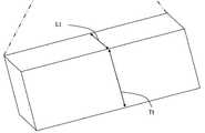
하나의 기술은 상기 중심 빔이 여기서 제공된 내용으로 조작 가능하게 될 소정의 구성을 가질 수 있는 것으로 이해할 것이다. 몇몇 실시예들에서, 적합한 중심 빔에 대한 기준들은 적합한 강도(stiffness)를 제공하는 재료 및 구성의 조합을 포함할 수 있다. 몇몇 실시예들에서, 상기 중심 빔은 I-빔을 포함할 수 있다.It will be appreciated that one technique may have a predetermined configuration in which the center beam will become operable with the contents provided herein. In some embodiments, the criteria for a suitable center beam may include a combination of materials and configurations that provide adequate stiffness. In some embodiments, the center beam may comprise an I-beam.
하나의 기술은 상기 중심 빔이 여기서 제공된 내용으로 조작 가능하게 될 이식 포트 구성들의 임의의 하나 또는 임의의 조합을 가질 수 있는 것으로 추가로 이해할 것이다. 몇몇 실시예들에서, 적합한 이식 포트 구성에 대한 기준들은 포트 사이즈, 포트들의 수, 포트들의 배치의 조합을 포함할 수 있다. 몇몇 실시예들에서, 상기 중심 빔은 측면 이식 포트(side graft port)를 포함할 수 있다.One technique will further understand that the center beam may have any one or any combination of implant port configurations to be operable with the contents provided herein. In some embodiments, the criteria for a suitable graft port configuration may include a combination of port size, number of ports, and placement of ports. In some embodiments, the center beam may include a side graft port.
하나의 기술은 상기 커넥터 소자들이 설계가 다양할 수 있지만 여기서 교시된 제한들을 충족시켜야 하는 것으로 추가로 이해할 것이다. 몇몇 실시예들에서, 예를 들어, 상기 커넥터 소자들 각각은 1:2에서 1:8까지의 범위의 두께를 가로지르도록 길이방향 두께의 횡단면 종횡비(aspect ratio)를 가질 수 있다.One technique will further understand that the connector elements may be of varying designs but must meet the limitations taught herein. In some embodiments, for example, each of the connector elements may have a longitudinal aspect ratio cross-sectional aspect ratio to cross a thickness in the range of 1: 2 to 1: 8.
몇몇 실시예들에서, 복수의 근위 커넥터 소자들 각각은 상기 확장된 상태에서 적어도 실질적으로 평행한 정렬로 구성된 근위 버팀대들(proximal struts)이고; 및, 상기 말단 커넥터 소자들 각각은 상기 확장된 상태에서 적어도 실질적으로 평행한 정렬로 구성된 말단 버팀대들(distal struts)이다. 이와 유사하게, 몇몇 실시예들에서, 상기 복수의 근위 커넥터 소자들 각각은 상기 접혀진 상태에서 적어도 실질적으로 평행한 정렬로 구성된 근위 버팀대들이고; 및, 상기 말단 커넥터 소자들 각각은 상기 접혀진 상태에서 적어도 실질적으로 평행한 정렬로 구성된 말단 버팀대들이다. 또한, 몇몇 실시예들에서, 상기 복수의 근위 커넥터 소자들 각각은 상기 확장된 상태와 상기 접혀진 상태에서 적어도 실질적으로 평행한 정렬로 구성된 근위 버팀대들이고; 및, 상기 말단 커넥터 소자들 각각은 상기 확장된 상태와 상기 접혀진 상태에서 적어도 실질적으로 평행한 정렬로 구성된 말단 버팀대들이다.In some embodiments, each of the plurality of proximal connector elements is proximal struts configured in at least substantially parallel alignment in the expanded state; And each of the distal connector elements is distal struts of at least substantially parallel alignment in the expanded state. Similarly, in some embodiments, each of the plurality of proximal connector elements is a proximal brace configured with at least substantially parallel alignment in the folded condition; And each of said distal connector elements is a distal brace configured in at least substantially parallel alignment in said folded condition. Also, in some embodiments, each of the plurality of proximal connector elements is a proximal strut configured with an alignment at least substantially parallel to the expanded and collapsed states; And each of the distal connector elements is a distal brace configured to be at least substantially parallel alignment in the expanded state and the folded state.
몇몇 실시예들에서, 복수의 근위 최상부 커넥터 소자들과 근위 바닥 커넥터 소자들 각각은 상기 확장된 상태와 상기 접혀진 상태에서 적어도 실질적으로 평행한 정렬로 구성된 근위 버팀대들이고; 및, 복수의 말단 최상부 커넥터 소자들과 말단 바닥 커넥터 소자들 각각은 상기 확장된 상태와 상기 접혀진 상태에서 적어도 실질적으로 평행한 정렬로 구성된 말단 버팀대들이다. 몇몇 실시예들에서, 상기 근위 최상부 버팀대들은 상기 제1 최상부 빔과 상기 제2 최상부 빔에 하나로 통제되어(monolithically) 일체로 구성되고; 및, 상기 말단 최상부 버팀대들은 상기 제1 최상부 빔과 상기 제2 최상부 빔에 하나로 통제되어 일체로 구성되고, 접혀져 있는 동안에 상기 근위 최상부 버팀대들을 향하여 구부려지도록(flex) 적응된다. 이와 유사하게, 몇몇 실시예들에서, 상기 근위 바닥 버팀대들은 상기 제1 바닥 빔과 상기 제2 바닥 빔에 하나로 통제되어 일체로 구성되고, 접혀져 있는 동안에 상기 말단 바닥 버팀대들을 향하여 구부려지도록 적응되고; 및, 상기 말단 바닥 버팀대들은 상기 제1 바닥 빔과 상기 제2 바닥 빔에 하나로 통제되어 일체로 구성되고, 접혀져 있는 동안에 상기 근위 바닥 버팀대들을 향하여 구부려지도록 적응된다. 그리고, 이러한 실시예들에서, 상기 측전으로의-확장 프레임의 상기 최상부와 바닥은 상기 척추간 공간 내에 이식 분배를 가능하게 하기 위해 확장시에 이식 분배 창을 개방하도록 각각 구성된다.In some embodiments, each of the plurality of proximal top connector elements and proximal bottom connector elements is a proximal brace configured with at least a substantially parallel alignment in the expanded and collapsed states; And each of the plurality of terminal top connector elements and the terminal bottom connector elements are terminal braces configured in at least substantially parallel alignment in the expanded state and the folded state. In some embodiments, the proximal upper braces are monolithically integrated into the first top beam and the second top beam; And the distal top struts are integrally configured and controlled to be integral with the first top beam and the second top beam and are flexed to flex toward the proximal top struts during folding. Similarly, in some embodiments, the proximal bottom struts are integrally configured and controlled to be integral with the first bottom beam and the second bottom beam, and are adapted to be bent toward the distal bottom struts during folding; And the distal bottom struts are integrally configured and controlled in one of the first bottom beam and the second bottom beam and are adapted to be bent toward the proximal bottom strut while being folded. And, in these embodiments, the top and bottom of the metering-expanding frame are each configured to open the implantation distribution window upon expansion to enable implantation distribution within the intervertebral space.
몇몇 실시예들에서, 상기 중심 빔은 제1 측면 이식 포트와 제2 측면 이식 포트를 더 포함한다. 이러한 실시예들에서, 각각의 복수의 근위 커넥터 소자들은 상기 확장된 상태와 상기 접혀진 상태에서 적어도 실질적으로 평행한 정렬의 근위 버팀대들로서 구성될 수 있고; 및, 각각의 복수의 말단 커넥터 소자들은 상기 확장된 상태와 상기 접혀진 상태에서 적어도 실질적으로 평행한 정렬로 구성될 수 있는 말단 버팀대들이다. 이와 같이, 상기 근위 최상부 버팀대들은 상기 제1 최상부 빔과 상기 제2 최상부 빔에 하나로 통제되어 일체로 구성되고, 접혀져 있는 동안에 상기 말단 최상부 버팀대들을 향하여 구부려지도록 적응될 수 있고; 및, 상기 말단 최상부 버팀대들은 상기 제1 최상부 빔과 상기 제2 최상부 빔에 하나로 통제되어 일체로 구성되고, 접혀져 있는 동안에 상기 근위 최상부 버팀대들을 향하여 구부려지도록 적응될 수 있다. 이와 유사하게, 상기 근위 바닥 버팀대들은 상기 제1 바닥 빔과 상기 제2 바닥 빔에 하나로 통제되어 일체로 구성되고, 접혀져 있는 동안에 상기 말단 바닥 버팀대들을 향하여 구부려지도록 적응될 수 있고; 및, 상기 말단 바닥 버팀대들은 상기 제1 바닥 빔과 상기 제2 바닥 빔에 하나로 통제되어 일체로 구성되고, 접혀져 있는 동안에 상기 근위 바닥 버팀대들을 향하여 구부려지도록 적응될 수 있다. 이와 유사하게, 상기 근위 제1 측 버팀대들은 상기 제1 최상부 빔과 상기 제1 바닥 빔에 하나로 통제되어 일체로 구성되고, 접혀져 있는 동안에 상기 말단 제1 측 버팀대들을 향하여 구부려지도록 적응될 수 있고; 및, 상기 말단 제1 측 버팀대들은 상기 제1 최상부 빔과 상기 제1 바닥 빔에 하나로 통제되어 일체로 구성되고, 접혀져 있는 동안에 상기 근위 제1 측 버팀대들을 향하여 구부려지도록 적응될 수 있다. 이와 유사하게, 상기 근위 제2 측 버팀대들은 상기 제2 최상부 빔과 상기 제2 바닥 빔에 하나로 통제되어 일체로 구성되고, 접혀져 있는 동안에 상기 말단 제2 측 버팀대들을 향하여 구부려지도록 적응될 수 있고; 및, 상기 말단 제2 측 버팀대들은 상기 제2 최상부 빔과 상기 제2 바닥 빔에 하나로 통제되어 일체로 구성되고, 접혀져 있는 동안에 상기 근위 제2 측 버팀대들을 향하여 구부려지도록 적응될 수 있다. 이처럼, 몇몇 실시예들에서는, 상기 측전으로의-확장 프레임의 상기 최상부, 바닥, 제1 측, 및 제2 측은 하나로 통제되는 일체적 프레임(integral frame)을 형성하도록 구성될 수 있고, 각각은 상기 척추간 공간 내에 이식 분배를 가능하게 하기 위해 확장시에 이식 분배 창(188)을 개방하도록 적응된다.In some embodiments, the center beam further comprises a first side implantation port and a second side implantation port. In such embodiments, each of the plurality of proximal connector elements may be configured as proximal struts of an alignment at least substantially parallel in the expanded state and the folded state; And each of the plurality of terminal connector elements is a distal brace that can be configured in at least substantially parallel alignment in the expanded state and the folded state. As such, the proximal upper struts can be adapted to be bent toward the distal upper strut while being integrally configured and controlled in one of the first top beam and the second top beam; And the terminal top struts are integrally configured and controlled as one with the first top beam and the second top beam and can be adapted to be bent towards the proximal top strut while being folded. Similarly, the proximal bottom struts can be adapted to be bent towards the distal bottom strands while being integrally configured and controlled in one of the first bottom beam and the second bottom beam; And the distal bottom struts are integrally configured and controlled in one of the first bottom beam and the second bottom beam, and may be adapted to be bent toward the proximal bottom strut while being folded. Similarly, the proximal first side braces may be adapted to be bent toward the distal first side braces while being folded and configured as one integral with the first top beam and the first bottom beam; And the distal first side struts are integrally configured to be integral with the first top beam and the first bottom beam and can be adapted to be bent toward the proximal first side strut while being folded. Similarly, the proximal second side braces may be adapted to be bent toward the distal second side braces while being folded and configured integrally with the second top beam and the second bottom beam; And the distal second strut may be adapted to be bent toward the proximal second strut while being integrally configured and controlled in one of the second top beam and the second bottom beam. As such, in some embodiments, the top, bottom, first side, and second side of the expansion frame to the transmission can be configured to form an integral frame that is controlled in one, And is adapted to open the
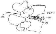
상기 내용들은 또한 여기서 교시된 소정의 상기 이식 분배 시스템들을 이용하여 척추간 공간을 유합하는 방법에 대한 것이다. 상기 방법들은 단일 진입점(single point of entry)을 추간판 내에 생성하는 것을 포함할 수 있고, 상기 추간판은 섬유테(annulus fibrosis)에 의해 둘러싸인 수핵(nucleus pulposus)을 가지고, 상기 단일 진입점은 상기 섬유테를 통해 생성된 최대 측방 치수를 가진다. 상기 방법들은 또한 상기 단일 진입점을 통해 상기 추간판 내에서부터 상기 수핵을 제거하는 것, 상기 이식 분배 시스템의 확장을 위한 상기 척추간 공간을 상기 섬유테 내에 남겨두는 것을 포함할 수 있고, 상기 척추간 공간은 최상부 척추판과 바닥 척추판을 가진다. 상기 방법들은 또한 상기 단일 진입점을 통해 상기 접혀진 상태에서의 상기 측전으로의 확장 프레임을 상기 척추간 공간에 삽입하는 것; 및, 상기 이식 분배 시스템을 형성하기 위해 상기 중심 빔을 상기 프레임에 삽입하는 것을 포함할 수 있다. 또한, 상기 방법들은 이식재를 상기 진입 포트를 통해 상기 척추간 공간에 추가하는 것을 포함할 수 있다.The above contents also relate to a method of unifying the intervertebral space using any of the above described graft delivery systems taught herein. The methods may include creating a single point of entry in an intervertebral disk, the intervertebral disc having a nucleus pulposus surrounded by annulus fibrosis, Lt; RTI ID = 0.0 > lateral < / RTI > The methods may also include removing the nucleus from within the intervertebral disc through the single entry point, leaving the intervertebral space for expansion of the graft delivery system within the fibrous sheath, It has an upper vertebra and a lower vertebral plate. The methods may also include inserting an expanded frame into the intervertebral space in the collapsed state through the single entry point; And inserting the center beam into the frame to form the graft delivery system. The methods may also include adding a implant to the vertebral space through the entry port.
여기서 제공된 상기 골 이식 분배 시스템들은 상기 커넥터 소자들에 의해 정의된 골 이식 창들을 포함하고, 상기 골 이식 창들은 상기 측전으로의 확장 프레임의 확장시에 개방(open)한다. 몇몇 실시예들에서, 상기 방법은 골 이식창을 개방하는 것을 포함하고, 상기 커넥터 소자들은 (i) 상기 척추간 공간으로의 수직 및 측방 모두로의 상기 시스템의 저-프로파일 입구(entry)에 대해 빈 공간을 최소화시키기 위해 상기 접혀진 상태에서의 폐쇄된-상호보완적(closed-complementary) 구성에서 근위로 또는 말단으로 적층(stack)하고, 및 (ii) 상기 골 이식 창을 개방하기 위해 확장시에 방향을 돌리는(deflect) v-형태의 버팀대들을 포함한다.The bone graft delivery systems provided herein include bone grafting windows defined by the connector elements and the bone grafting windows open upon expansion of the expandable frame to the posture. In some embodiments, the method includes opening a bone grafting window, the connector elements having (i) a low-profile entry of the system both vertically and laterally into the intervertebral space Stacking a proximal or distal end in a closed-complementary configuration in the folded state to minimize void space, and (ii) And includes deflecting v-shaped braces.
여기서 제공된 상기 골 이식 분배 시스템들은 또한 단계적으로 확장하는 것에 의한 측방 및 수직으로의 독립적인 확장을 허용한다. 몇몇 실시예들에서, 상기 확장은 수직 확장량에 독립적인 측방 확장량을 선택하는 것을 포함한다. 그리고, 몇몇 실시예들에서, 상기 측방 확장은 상기 척추간 공간으로의 상기 단일 진입점인 상기 환형 개구의 폭을 초과한다. 예를 들어, 상기 단일 진입점의 상기 측방 치수는 몇몇 실시예들에서 약 5 밀리미터 내지 약 15 밀리미터까지의 범위일 수 있다. 이와 같이, 몇몇 실시예들에서, 상기 확장은 상기 단일 진입점의 폭을 초과하는 폭까지 상기 측전으로의 확장 프레임을 측방으로 확장하는 것; 및, 상기 이식 분배 시스템을 생성하기 위해 상기 측전으로의 확장 프레임을 수직으로 확장하도록 상기 중심 빔을 삽입하는 것을 포함한다.The bone graft delivery systems provided herein also allow for independent lateral and vertical expansion by stepwise expansion. In some embodiments, the expansion includes selecting a lateral expansion amount that is independent of the vertical expansion amount. And, in some embodiments, the lateral extension exceeds the width of the annular opening that is the single entry point into the intervertebral space. For example, the lateral dimension of the single entry point may range from about 5 millimeters to about 15 millimeters in some embodiments. Thus, in some embodiments, the extension sideways extends the extension frame to the transmission to a width that exceeds the width of the single entry point; And inserting the center beam to vertically extend the extension frame to the metering to create the graft delivery system.
여기서 제공된 상기 골 이식 분배 시스템들은 또한 상기 측전으로의 확장 프레임에 상기 중심 빔을 유지(retain)하기 위한 수단을 가진다. 몇몇 실시예들에서, 상기 중심 빔을 상기 측전으로의 확장 프레임으로 삽입하는 것은 상기 확장 후에 상기 중심 빔의 상기 측전으로의-확장 프레임의 백아웃을 방지하기 위해 상기 측전으로의-확장 프레임과 체결하는 상기 중심 빔 상의 돌기(protuberance)를 포함하는 래칫 메카니즘(ratchet mechanism)을 체결하는 것을 포함한다.The bone graft delivery systems provided herein also have means for retaining the center beam in an expansion frame to the metering. In some embodiments, inserting the center beam into the extension frame into the offset may include locking the extension frame to the offset to prevent backout of the extension frame of the center beam to the offset after the extension. And a ratchet mechanism including a protuberance on the central beam that makes the center beam.
여기서 제공된 상기 골 이식 분배 시스템들은 키트(kit)의 형태일 수 있다. 상기 키트들은, 예를 들어, 여기서 교시된 이식 분배 시스템, 상기 척추간 공간에 상기 이식 분배 시스템을 삽입하기 위한 캐뉼라(cannula), 상기 중심 빔을 상기 측전으로의 확장 프레임으로 유도하도록 적응된 유도선, 및 상기 이식 분배 시스템을 형성하기 위해 상기 중심 빔을 상기 측전으로의 확장 프레임으로 삽입하기 위한 확장 핸들(expansion handle)을 포함할 수 있다.The bone graft delivery systems provided herein may be in the form of a kit. The kits may include, for example, a graft delivery system taught herein, a cannula for insertion of the graft delivery system into the intervertebral space, a guide wire adapted to guide the center beam to an expansion frame to the delivery, And an expansion handle for inserting the center beam into the expansion frame to the transmission to form the graft distribution system.
본 발명에 따르면, 척추간 공간을 통해 이식재의 향상된 분배를 가능하게 하는 골 이식 분배 시스템들이 제공된다.BRIEF SUMMARY OF THE INVENTION In accordance with the present invention, bone graft delivery systems are provided that enable improved distribution of the implant through the intervertebral space.
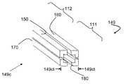
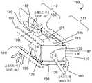
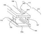
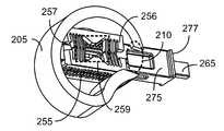
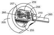
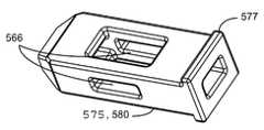
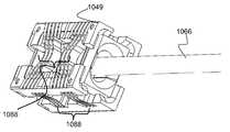
도 1a 내지 1i는 몇몇 실시예들에 따라 상기 이식 분배 시스템(graft distribution system)의 요소들을 도시한다.
도 2a 내지 2f는 몇몇 실시예들에 따라 양방향으로-확장가능한 케이지(cage)를 사용하는 방법을 도시한다.
도 3a 내지 3d는 몇몇 실시예들에 따라 추간판 공간(intervertebral disc space)을 유합(fusing)하기 위한 양방향으로-확장가능한 케이지를 도시한다.
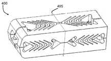
도 4a 및 4b는 몇몇 실시예들에 따라 추간판 공간을 유합하기 위한 각각의 벽 상의 골 이식 창(bone graft window)을 갖는 양방향으로-확장가능한 케이지의 접혀진 및 확장된 그림을 도시한다.
도 5a 내지 5d는 몇몇 실시예들에 따라 추간판 공간을 유합하기 위한 시스템을 도시한다.
도 6은 몇몇 실시예들에 따라 양방향으로-확장가능한 케이지를 사용하는 방법의 다이어그램(diagram)이다.
도 7a 내지 7f는 몇몇 실시예들에 따라 이식 분배 시스템들의 몇몇 추가적인 특징들을 도시한다.
도 8a 내지 8d는 몇몇 실시예들에 따른 이식 분배 키트(graft distribution kit)의 요소들을 도시한다.
도 9a 내지 9c는 몇몇 실시예들에 따른 척추간 공간 내의 측전으로의-확장가능한(laterovertically-expandable) 프레임의 확장을 도시한다.
도 10a 내지 10c는 몇몇 실시예들에 따라 상기 탈출 포트들 및 골 이식 창들을 강조(highlight)하기 위한 확장된 이식 분배 시스템의 프로파일들(profiles)을 도시한다.
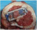
도 11a 및 11b는 몇몇 실시예들에 따라 상대적인 크기(size)를 나타내기 위해 제자리에 있는 상기 이식 분배의 도시와 카데바(cadaver) 내의 테스트 배치를 비교한다.
도 12a 내지 12c는 몇몇 실시예들에 따른 카데바 내에서의 배치의 x-선들을 나타낸다.
도 13a 및 13b는 몇몇 실시예들에 따른, 제2 최상부 빔(top beam)에 대한 제1 최상부 빔, 제2 바닥 빔(bottom beam)에 대한 제1 바닥 빔, 상기 제1 바닥 빔에 대한 상기 제1 최상부 빔, 및 상기 제2 바닥 빔에 대한 상기 제2 최상부 빔의 방향들(orientations)을 나타낸다.Figures 1A-1I illustrate the elements of the graft distribution system in accordance with some embodiments.
Figures 2a-2f illustrate a method of using a bi-directionally-extendable cage in accordance with some embodiments.
Figures 3A-3D illustrate a bi-directionally-extendable cage for fusing an intervertebral disc space according to some embodiments.
Figures 4a and 4b illustrate a folded and expanded view of a bi-directionally-extendable cage with a bone graft window on each wall to unite the intervertebral disc space according to some embodiments.
Figures 5A-5D illustrate a system for unifying intervertebral disc spaces according to some embodiments.
Figure 6 is a diagram of a method of using a bi-directionally-extendable cage in accordance with some embodiments.
Figures 7A-7F illustrate some additional features of implant delivery systems in accordance with some embodiments.
Figures 8A-8D illustrate elements of a graft distribution kit according to some embodiments.
Figures 9A-9C illustrate the extension of a laterovertically-expandable frame in the interbody space in accordance with some embodiments.
Figures 10A-10C illustrate profiles of an expanded graft delivery system for highlighting the escape ports and bone grafting windows in accordance with some embodiments.
Figures 11A and 11B compare the test placement in the cadaver with the city of the implant distribution in place to indicate the relative size in accordance with some embodiments.
Figures 12a-12c illustrate x-rays of a placement in a Kadena according to some embodiments.
13A and 13B illustrate a first top beam for a second top beam, a first bottom beam for a second bottom beam, a second bottom beam for a second bottom beam, The first top beam, and the orientations of the second top beam relative to the second bottom beam.
여기서의 내용들은 보통 추간판 공간(intervertebral disc space)에 골 이식재(bone graft material)를 분배하기 위한 시스템을 나타낸다. 상기 이식 분배 시스템은, 예를 들어, 종단(end)을 갖는 근위부(proximal portion), 최상부(top)와 바닥(bottom)을 갖는 이식부(grafting portion), 종단을 갖는 말단부(distal portion), 중심 빔 축, 및 상기 근위부의 종단에 진입 포트(entry port)를 갖는 이식 분배 채널(graft distribution channel), 상기 이식부의 최상부에의 최상부 탈출 포트(top exit port), 상기 이식부의 바닥의 바닥 탈출 포트(bottom exit port)를 가지는 중심 빔(central beam)을 가질 수 있다. 이러한 시스템들은 또한 루멘(lumen)을 갖는 측전으로의-확장 프레임(laterovertically-expanding frame), 제1 최상부 빔, 제2 최상부 빔, 제1 바닥 빔, 및 제2 바닥 빔을 포함할 수 있고, 각각은 근위부와 말단부를 가지고, 각각은 확장된 상태로부터 접혀진 상태(collapsed state)로의 가역적인 접힘(reversible collapse)에 대해 조작 가능한 상기 측전으로의-확장 프레임을 형성하기 위해 그들 각각의 근위부들과 말단부들에서 커넥터 소자들과 서로 조작 가능하게 연결된다. 상기 확장된 상태는, 예를 들어, 적어도 실질적으로 상기 가역적인 접힘에 근접한 개방된 이식 분배창(open graft distribution window)을 갖도록 구성될 수 있다. 이러한 실시예들에서, 상기 측전으로의-확장 프레임은 상기 이식 분배 시스템을 형성하기 위해 상기 중심 빔의 삽입을 수용하도록 적응된다.The contents here represent a system for distributing bone graft material to an intervertebral disc space. The grafting and distribution system may include, for example, a proximal portion having an end, a grafting portion having a top and a bottom, a distal portion having a terminus, A graft distribution channel having a beam axis and an entry port at the end of the proximal portion, a top exit port at the top of the implant, a bottom exit port at the bottom of the implant, and a bottom exit port. These systems may also include a laterovertically-expanding frame with a lumen, a first top beam, a second top beam, a first bottom beam, and a second bottom beam, Each having a proximal end and a distal end, each having a proximal end and a distal end, each of which is operable against a reversible collapse from an expanded state to a collapsed state, Which are operatively connected to the connector elements. The expanded state can be configured, for example, to have an open graft distribution window at least substantially close to the reversible fold. In these embodiments, the post-extension frame is adapted to accommodate insertion of the center beam to form the implant delivery system.
몇몇 실시예들에서, 상기 이식 분배 시스템들은 또한, 제1 최상부 빔, 제2 최상부 빔, 제1 바닥 빔, 및 제2 바닥 빔을 갖는 측전으로의-확장 프레임을 포함할 수 있고; 상기 빔들은 적어도 실질적으로 서로 평행하게 배열되고, 각각은 근위부, 이식부, 및 말단부를 가지고, 및 각각은 확장된 상태로부터 접혀진 상태로의 가역적인 접힘에 대해 조작 가능한 사각 원통형(square cylindrical shape)으로 상기 측전으로의-확장 프레임을 형성하도록 그들 각각의 근위부들과 말단부들에서 서로 조작 가능하게 연결된다. 상기 확장된 상태는, 예를 들어, 적어도 실질적으로 상기 가역적인 접힘에 근접한 개방된 이식 분배창을 가지도록 구성될 수 있다. 이러한 실시예들에서, 상기 측전으로의-확장 프레임은 상기 이식 분배 시스템을 형성하도록 상기 중심 빔의 삽입을 수용하도록 적응된다.In some embodiments, the graft delivery systems may also include a transfuse-extending frame having a first top beam, a second top beam, a first bottom beam, and a second bottom beam; The beams are arranged at least substantially parallel to each other, each having a proximal portion, an implanted portion, and a distal portion, and each having a substantially square cylindrical shape operable for reversible folding from an expanded state to a folded state And are operably connected to each other at their respective proximal and distal ends to form an expanded frame to said transducer. The expanded condition may, for example, be configured to have an open graft distribution window at least substantially close to the reversible fold. In these embodiments, the post-extension frame is adapted to accommodate insertion of the center beam to form the implant delivery system.
"대상" 및 "환자"라는 용어는 몇몇 실시예들에서 번갈아 사용될 수 있고, 이에 한정되지는 않지만, 예를 들어 소, 돼지, 말, 고양이, 개와 같은 비-영장류; 및 예를 들어 원숭이 또는 사람과 같은 영장류를 포함하는 포유동물 등의 동물을 나타낸다. 이와 같이, 상기 용어들 "대상" 및 "환자"는 또한 이에 한정되지는 않지만, 수의학(veterinary), 반려 동물(companion animals), 상용 가축(commercial livestock) 등을 포함하는 비-인간 생물학 응용에 적용될 수 있다. 또한, 정도(degree)의 용어들은 여기서 교시된 상기 시스템들의 요소들의 위치 및/또는 이동 사이의 상대적인 관계를 제공하기 위해 여기서 사용된다. 예를 들어, "적어도 실질적으로 평행한"이라는 절은 다른 것에 대한 하나의 요소의 위치를 나타내도록 사용된다. 다른 축에 대해 적어도 실질적으로 평행한 축은 평행하게 되는 모든 실현 가능한 목적에 대해 의도되는 방향을 나타내지만, 이는 단지 편리한 언급으로 이해되고, 상기 시스템으로의 내부 응력(stresses) 및 상기 기기들과 시스템들에서의 결함으로 인해 변형들이 있을 수 있다. 이와 유사하게, "적어도 실질적으로 평면 상에"라는 절은 방향 또는 이동의 편리한 측정으로서의 상기 평면 상에 또는 가까이에 있는 모든 실현 가능한 목적에 대해 의도되는 방향 또는 이동을 나타내지만, 이는 단지 편리한 언급으로 이해되고, 상기 시스템으로의 내부 응력 및 상기 기기들과 시스템들에서의 결함으로 인해 변형들이 있을 수 있다. 이와 유사하게, "적어도 실질적으로 일치하는"이라는 절은 예를 들어 방향 또는 이동의 편리한 측정으로서의 축이나 평면 상에 또는 가까이에 있는 모든 실현 가능한 목적에 대해 의도되는 방향 또는 이동을 나타내지만, 이는 단지 편리한 언급으로 이해되고, 상기 시스템으로의 내부 응력(stresses) 및 상기 기기들과 시스템들에서의 결함으로 인해 변형들이 있을 수 있다.The terms "subject" and "patient" may be used interchangeably in some embodiments, and include, but are not limited to, non-primates such as cattle, pigs, horses, cats, dogs; And mammals including primates such as, for example, monkeys or humans. As such, the terms "subject" and "patient" are intended to encompass all types of non-human biological applications including, but not limited to, veterinary, companion animals, commercial livestock, . Also, terms of degree are used herein to provide a relative relationship between the location and / or movement of the elements of the systems taught herein. For example, the phrase "at least substantially parallel" is used to denote the position of one element relative to the other. It should be understood that this is only a convenient reference, and that the internal stresses to the system and the devices and systems < RTI ID = 0.0 > There may be deformations due to defects in the. Similarly, the phrase "at least substantially on a plane" refers to a direction or movement intended for all possible purposes on or near the plane as a convenient measure of direction or movement, It is understood that there may be deformations due to internal stresses into the system and defects in the devices and systems. Similarly, the phrase "at least substantially coincident " indicates, for example, a direction or movement intended for all possible purposes on or near an axis or plane as a convenient measurement of direction or movement, It is understood to be a convenient reference, and there may be variations due to internal stresses to the system and defects in the devices and systems.
도 1a 내지 1i는 몇몇 실시예들에 따른 상기 이식 분배 시스템의 요소들을 도시한다. 도 1a에서 나타나는 것처럼, 상기 이식 분배 시스템들(100)은 중심 빔 축(105)을 구비한 중심 빔(101), 최상부 탈출 포트(140)와 유체 연통(fluid communication)하는 진입 포트(135)를 구비한 이식 분배 채널, 및 바닥 탈출 포트(141)를 가질 수 있다. 상기 중심 빔(101)은 상기 진입 포트(135)를 구비한 종단을 갖는 근위부(111), 상기 최상부 탈출 포트(140)와 상기 바닥 탈출 포트(141)를 갖는 이식부(112), 및 말단부(도시되지 않음)를 가질 수도 있다. 상기 중심 빔(101)은 5 밀리미터 내지 15 밀리미터 범위의 최대 측방 치수를 갖는 환영 개구(annular opening)를 통해 상기 중심 빔(101)을 척추간 공간 내에 위치시키기 위한 5 밀리미터 내지 15 밀리미터 범위의 최대 치수를 갖는 체축단(transverse cross-section)을 갖도록 크기 조정될 수도 있고, 상기 척추간 공간은 최상부 척추판과 바닥 척추판을 가진다. 상기 중심 빔(101)은 제1 최상부-측방 표면(top-lateral surface, 117)과 제2 최상부-측방 표면(119)을 구비한 최상부 표면(top surface, 115), 제1 바닥-측방 표면(112)과 제2 바닥-측방 표면(124)을 구비한 바닥 표면(120), 제1 최상부-측 표면(top-side surface, 127)과 제1 바닥-측 표면(129)을 구비한 제1 측 표면(125), 및 제2 최상부-측 표면(132)과 제2 바닥-측 표면(134)을 구비한 제2 측 표면(130)을 가질 수도 있다.Figs. 1A-1I illustrate the elements of the implant delivery system according to some embodiments. 1A, the
몇몇 실시예들에서, 상기 중심 빔은 약 5 밀리미터 내지 약 15 밀리미터 범위의 체축단 측방 치수를 가질 수 있다. 몇몇 실시예들에서, 상기 중심 빔의 수직 치수는 약 4 밀리미터 내지 약 12 밀리미터, 약 5 밀리미터 내지 약 11 밀리미터, 약 6 밀리미터 내지 약 10 밀리미터, 및 약 7 밀리미터 내지 약 9 밀리미터, 약 6 밀리미터 내지 약 8 밀리미터, 약 6 밀리미터의 범위 또는 거기서 1 밀리미터의 증가분(increments)으로의 임의의 범위나 양일 수 있다. 몇몇 실시예들에서, 상기 중심 빔의 측방 치수는 약 5 밀리미터 내지 약 15 밀리미터, 약 6 밀리미터 내지 약 14 밀리미터, 약 7 밀리미터 내지 약 13 밀리미터, 약 8 밀리미터 내지 약 12 밀리미터, 약 10 밀리미터 또는 거기서 1 밀리미터의 증가분으로의 임의의 범위나 양일 수 있다. 몇몇 실시예들에서, 상기 중심 빔의 체축단은 약 2 밀리미터 내지 약 20 밀리미터, 약 3 밀리미터 내지 약 18 밀리미터, 약 4 밀리미터 내지 약 16 밀리미터, 약 5 밀리미터 내지 약 14 밀리미터, 약 6 밀리미터 내지 약 12 밀리미터, 약 7 밀리미터 내지 약 10 밀리미터의 범위 또는 거기서의 소정의 범위인 효과적인 직격을 구비한 영역을 가진다. 몇몇 실시예들에서, 상기 저-프로파일(low profile)은 2 밀리미터, 4 밀리미터, 6 밀리미터, 8 밀리미터, 10 밀리미터, 12 밀리미터, 14 밀리미터, 16 밀리미터, 18 밀리미터, 또는 거기서의 소정의 범위의 직경을 구비한 영역으로서, 거기서의 임의의 이러한 직경 또는 범위에서 1 밀리미터의 소정의 증가분을 포함하는 영역을 가진다. 몇몇 실시예들에서, 상기 중심 빔의 상기 폭(밀리미터) x 높이(밀리미터)는 9.0 x 5.0, 9.0 x 6.0, 9.0 x 7.0, 9.0 x 8.0, 9.0 x 9.0, 및 9.0 x 10.0일 수 있고, 거기서의 치수에서의 소정의 편차는 +/- 0.1 밀리미터의 증가분이다. 그리고, 몇몇 실시예들에서, 상기 중심 빔은 6.5 밀리미터 내지 14.0 밀리미터의 범위인 체축단 측방 또는 수직 치수를 가질 수 있다.In some embodiments, the center beam may have a body-side lateral dimension ranging from about 5 millimeters to about 15 millimeters. In some embodiments, the vertical dimension of the center beam is from about 4 millimeters to about 12 millimeters, from about 5 millimeters to about 11 millimeters, from about 6 millimeters to about 10 millimeters, and from about 7 millimeters to about 9 millimeters, from about 6 millimeters About 8 millimeters, about 6 millimeters, or any range or amount there in increments of one millimeter. In some embodiments, the lateral dimension of the center beam is about 5 millimeters to about 15 millimeters, about 6 millimeters to about 14 millimeters, about 7 millimeters to about 13 millimeters, about 8 millimeters to about 12 millimeters, about 10 millimeters, It can be any range or amount in increments of 1 millimeter. In some embodiments, the body axis of the center beam is about 2 millimeters to about 20 millimeters, about 3 millimeters to about 18 millimeters, about 4 millimeters to about 16 millimeters, about 5 millimeters to about 14 millimeters, about 6 millimeters to about 8 millimeters 12 millimeters, a range of about 7 millimeters to about 10 millimeters, or an effective strike of a predetermined range there. In some embodiments, the low profile has a diameter in the range of 2 millimeters, 4 millimeters, 6 millimeters, 8 millimeters, 10 millimeters, 12 millimeters, 14 millimeters, 16 millimeters, 18 millimeters, Having an area containing a predetermined increment of 1 millimeter in any such diameter or range there. In some embodiments, the width (millimeter) x height (millimeter) of the center beam may be 9.0 x 5.0, 9.0 x 6.0, 9.0 x 7.0, 9.0 x 8.0, 9.0 x 9.0, and 9.0 x 10.0, 0.0 > +/- 0.1 < / RTI > millimeter. And, in some embodiments, the center beam may have a body side or vertical dimension ranging from 6.5 millimeters to 14.0 millimeters.
도 1b 및 1c에 나타나는 것처럼, 상기 이식 분배 시스템(100)은 생체 내(in vivo) 이식 분배 시스템(100)을 생성하기 위해 상기 중심 빔(101)과 조작 가능하게 접촉하도록 구성된 측전으로의-확장 프레임(149)을 포함할 수도 있고, 상기 프레임(149)은 확장을 위해 상기 환형 개구를 통해 상기 프레임(149)을 상기 척추간 공간 내에 위치시키기 위한 5 밀리미터 내지 15 밀리미터 범위의 최대 치수를 갖는 체축단(149ct)을 구비한 접혀진 상태(149c)를 가진다. 이와 유사하게, 상기 프레임(149)은 상기 프레임(149)을 상기 척추간 공간 내에 유지하기 위해 6.5 밀리미터 내지 18 밀리미터 범위의 최대 치수를 갖는 체축단(149et)을 구비한 확장된 상태를 가질 수도 있고, 상기 확장된 상태는 상기 척추간 공간 내에서 상기 중심 빔(101)과 조작 가능하게 접촉한다. 상기 프레임(149)은 종단을 갖는 근위부(111), 이식부(112), 종단을 갖는 말단부(도시되지 않음), 및 상기 확장된 상태(149e)의 중심 프레임 축(113)을 포함하는 것으로 정의될 수 있다.1b and 1c, the
몇몇 실시예들에서, 상기 프레임은 약 5 밀리미터 내지 약 15 밀리미터 범위의 상기 접혀진 상태에서의 체축단 측방 치수를 가질 수 있다. 몇몇 실시예들에서, 상기 접혀진 상태에서의 상기 프레임의 수직 치수는 약 4 밀리미터 내지 약 12 밀리미터, 약 5 밀리미터 내지 약 11 밀리미터, 약 6 밀리미터 내지 약 10 밀리미터, 및 약 7 밀리미터 내지 약 9 밀리미터, 약 6 밀리미터 내지 약 8 밀리미터의 범위, 약 6 밀리미터 또는 거기서 1 밀리미터의 증가분으로의 임의의 범위 또는 양일 수 있다. 몇몇 실시예들에서, 상기 접혀진 상태에서의 상기 프레임의 측방 치수는 약 5 밀리미터 내지 약 15 밀리미터, 약 6 밀리미터 내지 약 14 밀리미터, 약 7 밀리미터 내지 약 13 밀리미터, 약 8 밀리미터 내지 약 12 밀리미터의 범위, 약 10 밀리미터 또는 거기서 1 밀리미터의 증가분으로의 임의의 범위 또는 양일 수 있다. 몇몇 실시예들에서, 상기 접혀진 상태에서의 상기 프레임의 체축단은 약 2 밀리미터 내지 약 20 밀리미터, 약 3 밀리미터 내지 약 18 밀리미터, 약 4 밀리미터 내지 약 16 밀리미터, 약 5 밀리미터 내지 약 14 밀리미터, 약 6 밀리미터 내지 약 12 밀리미터, 약 7 밀리미터 내지 약 10 밀리미터의 범위 또는 거기서의 임의의 범위인 효과적인 직경을 구비한 영역을 가진다. 몇몇 실시예들에서, 상기 저-프로파일은 2 밀리미터, 4 밀리미터, 6 밀리미터, 8 밀리미터, 10 밀리미터, 12 밀리미터, 14 밀리미터, 16 밀리미터, 18 밀리미터, 또는 거기서의 임의의 범위인 직경으로서, 거기서의 이러한 직경 또는 범위에서 임의의 1 밀리미터의 증가분을 포함하는, 직경을 구비한 영역을 가진다. 몇몇 실시예들에서, 상기 접혀진 상태에서의 폭(밀리미터) x 높이(밀리미터)는 9.0 x 5.0, 9.0 x 6.0, 9.0 x 7.0, 9.0 x 8.0, 9.0 x 9.0, 및 9.0 x 10.0일 수 있거나, 거기서 +/- 0.1 밀리미터의 증가분의 치수에서의 편차가 있다. 몇몇 실시예들에서, 상기 프레임은 4.0 밀리미터 내지 18 밀리미터, 5.0 밀리미터 내지 19.0밀리미터, 6.0 밀리미터 내지 17.5 밀리미터, 7.0 밀리미터 내지 17.0 밀리미터, 8.0 밀리미터 내지 16.5 밀리미터, 9.0 밀리미터 내지 16.0 밀리미터, 9.0 밀리미터 내지 15.5 밀리미터, 6.5 밀리미터 내지 15.5 밀리미터의 범위이거나, 또는 거기서 +/- 0.1 밀리미터의 증가분의 소정의 범위 또는 양(amount)인 상기 확장된 상태에서의 측방 또는 수직의 체축단 치수를 가질 수 있다.In some embodiments, the frame may have a body-side lateral dimension in the folded state ranging from about 5 millimeters to about 15 millimeters. In some embodiments, the vertical dimension of the frame in the folded state is from about 4 millimeters to about 12 millimeters, from about 5 millimeters to about 11 millimeters, from about 6 millimeters to about 10 millimeters, and from about 7 millimeters to about 9 millimeters, In the range of about 6 millimeters to about 8 millimeters, about 6 millimeters or there may be any range or amount in increments of one millimeter. In some embodiments, the lateral dimension of the frame in the folded state is in the range of about 5 millimeters to about 15 millimeters, about 6 millimeters to about 14 millimeters, about 7 millimeters to about 13 millimeters, about 8 millimeters to about 12 millimeters , About 10 millimeters or there may be any range or amount in increments of one millimeter. In some embodiments, the body end of the frame in the folded state is between about 2 millimeters and about 20 millimeters, between about 3 millimeters and about 18 millimeters, between about 4 millimeters and about 16 millimeters, between about 5 millimeters and about 14 millimeters, From about 6 millimeters to about 12 millimeters, from about 7 millimeters to about 10 millimeters, or any range there. In some embodiments, the low-profile has a diameter of 2 millimeters, 4 millimeters, 6 millimeters, 8 millimeters, 10 millimeters, 12 millimeters, 14 millimeters, 16 millimeters, 18 millimeters, or any range there, And has a region with a diameter, including any one millimeter increment in this diameter or range. In some embodiments, the width (millimeter) x height (millimeter) in the folded state may be 9.0 x 5.0, 9.0 x 6.0, 9.0 x 7.0, 9.0 x 8.0, 9.0 x 9.0, and 9.0 x 10.0, There is a deviation in dimension of increment of +/- 0.1 millimeter. In some embodiments, the frame has a width in the range of 4.0 millimeters to 18 millimeters, 5.0 millimeters to 19.0 millimeters, 6.0 millimeters to 17.5 millimeters, 7.0 millimeters to 17 millimeters, 8.0 millimeters to 16.5 millimeters, 9.0 millimeters to 16 millimeters, 9.0 millimeters to 15.5 millimeters , In the range of from 6.5 millimeters to 15.5 millimeters, or there may be lateral or vertical body-axis dimensions in the expanded state in a predetermined range or amount of increment of +/- 0.1 millimeters therefrom.
상기 용어 "접혀진 상태"는, 상기 체축단 영역 또는 프로파일이 적어도 실질적으로 그의 최소치에 있는 상기 프레임의 구성을 나타내는 데 사용될 수 있고, 상기 용어 "확장된 상태"는 적어도 실질적으로 상기 접혀진 상태를 넘어서 확장된 상기 프레임의 구성을 나타내는 데 사용될 수 있다. 이러한 맥락에서, 상기 프레임의 골 이식창이 상기 접혀진 상태로부터의 상기 골 이식창의 영역을 적어도 20% 증가시키는 것에 의해 상기 폐쇄된 구성으로부터 개방될 때, 프레임이 적어도 "실질적으로" 상기 접혀진 상태를 넘어 확장된다. 몇몇 실시예들에서, 상기 프레임의 골 이식창이 상기 접혀진 상태로부터의 상기 골 이식창과 비교할 때 적어도 15%, 20%, 25%, 30%, 35%, 40%, 45%, 50%, 60%, 70%, 80%, 90%, 100%, 150%, 200%, 250%, 300%, 또는 그 이상 개방될 때, 상기 프레임은 적어도 "실질적으로" 상기 접혀진 상태를 넘어 확장된다. 몇몇 실시예들에서, 상기 프레임의 골 이식창이 상기 접혀진 상태로부터의 상기 골 이식창과 비교할 때 적어도 2x, 3x, 5x, 10x, 15x, 20x, 또는 그 이상 개방될 때, 상기 프레임은 적어도 "실질적으로" 상기 접혀진 상태를 넘어 확장된다.The term " folded state "can be used to denote the configuration of the frame in which the body end region or profile is at least substantially at its minimum, and the term" extended state " Can be used to indicate the configuration of the frame. In this context, when a bone grafting window of the frame is opened from the closed configuration by at least 20% increase in area of the bone grafting window from the collapsed state, the frame is at least "substantially & do. In some embodiments, the bone grafting window of the frame has at least 15%, 20%, 25%, 30%, 35%, 40%, 45%, 50%, 60% , 70%, 80%, 90%, 100%, 150%, 200%, 250%, 300%, or more of the frame is opened at least "substantially" In some embodiments, when the bone grafting window of the frame is opened at least 2x, 3x, 5x, 10x, 15x, 20x, or more as compared to the bone grafting window from the collapsed state, "Extends beyond the collapsed state.
몇몇 실시예들에서, 상기 측전으로의 확장가능한 프레임들은 확장된 상태에서 생성된다. 그리고, 상기 확장된 상태는 전체 확장의 적어도 30%, 적어도 40%, 적어도 50%, 적어도 60%, 적어도 70%, 적어도 80%, 적어도 90%, 또는 적어도 95%인 상태를 포함할 수 있다. 상기 용어 "전체 확장"은 커넥터 소자가 피로, 실패, 또는 균열하기 시작하거나, 또는, 몇몇 실시예들에서, 10%, 20%, 또는 30%를 넘게 변형되기 시작하는 확장의 정도를 나타내는 데 사용될 수 있다.In some embodiments, the scalable frames to the offset are generated in an expanded state. And the expanded state may comprise at least 30%, at least 40%, at least 50%, at least 60%, at least 70%, at least 80%, at least 90%, or at least 95% of the total extension. The term "full extension" is used to denote the degree of expansion in which a connector element begins to fatigue, fail, or crack, or, in some embodiments, begin to deform by more than 10%, 20%, or 30% .
상기 프레임(149)은 종단을 갖는 근위부(111), 이식부(112), 및 종단을 갖는 말단부(도시되지 않음)를 포함하는 제1 최상부 빔(150)을 가지도록 구성될 수 있고, 상기 제1 최상부 빔(150)은 상기 확장된 상태(149e)에서의 상기 중심 빔의 상기 제1 최상부-측방 표면(117)과 상기 중심 빔(101)의 상기 제1 최상부-측 표면(127)에 접촉하도록 구성되고, 상기 제1 최상부 빔의 중심 축은 적어도 실질적으로 (i) 상기 제1 최상부 빔의 중심 축과 상기 제2 최상부 빔의 중심 축을 포함하는 최상부 평면과, (ii) 상기 제1 최상부 빔의 중심 축과 상기 제1 바닥 빔의 중심 축을 포함하는 제1 측 평면 상에 있다. 이와 유사하게, 상기 프레임(149)은 종단을 갖는 근위부(111), 종단을 갖는 이식부(112), 및 종단을 갖는 말단부(도시되지 않음)를 포함하는 제2 최상부 빔(160)을 가지도록 구성될 수 있고, 상기 제2 최상부 빔(160)은 상기 확장된 상태(149e)에서의 상기 중심 빔(101)의 상기 제2 최상부-측방 표면(119)과 상기 중심 빔(101)의 상기 제2 최상부-측 표면(132)에 접촉하도록 구성되고, 상기 제2 최상부 빔의 중심 축은 적어도 실질적으로 (i) 상기 최상부 평및 (ii) 상기 제2 최상부 빔의 중심 축과 상기 제2 바닥 빔의 중심 축을 포함하는 제2 측 평면 상에 있다. 이와 유사하게, 상기 프레임(149)은 종단을 갖는 근위부(111), 이식부(112), 및 종단을 갖는 말단부(도시되지 않음)를 포함하는 제1 바닥 빔(170)을 가지도록 구성될 수 있고, 상기 제1 바닥 빔(170)은 상기 확장된 상태(149e)에서 상기 중심 빔(101)의 상기 제1 바닥-측방 표면(122)과 상기 중심 빔(101)의 상기 제1 바닥-측 표면(129)에 접촉하도록 구성되고, 상기 제1 바닥 빔의 중심 축은 적어도 실질적으로 (i) 상기 제1 바닥 빔의 중심 축과 상기 제2 최상부 빔의 중심 축을 포함하는 바닥 평면, 및 (ii) 상기 제1 측 평면 상에 있다. 이와 유사하게, 상기 프레임(149)은 종단을 갖는 근위부(111), 종단을 갖는 이식부(112), 및 종단을 갖는 말단부(도시되지 않음)를 포함하는 제2 바닥 빔(180)을 가지도록 구성될 수 있고, 상기 제2 바닥 빔(160)은 상기 확장된 상태(149e)에서 상기 중심 빔(101)의 상기 제2 바닥-측방 표면(124)과 상기 중심 빔(101)의 상기 제2 바닥-측 표면(134)에 접촉하도록 구성되고, 상기 제2 바닥 빔의 중심 축은 적어도 실질적으로 (i) 상기 바닥 평면, 및 (ii) 상기 제2 바닥 빔과 상기 제2 최상부 빔의 중심 축을 포함하는 제2 측 평면 상에 있다.The
몇몇 실시예들에서, 상기 제1 최상부 빔(150)의 중심 축은 상기 중심 빔 축(105)에 적어도 실질적으로 평행할 수 있다. 이와 유사하게, 상기 프레임(149)은 종단을 갖는 근위부(111), 종단을 갖는 이식부(112), 종단을 갖는 말단부(도시되지 않음)를 포함하는 제2 최상부 빔(160)을 가지도록 구성될 수 있고, 상기 제2 최상부 빔(160)은 상기 확장된 상태(149e)에서 상기 중심 빔(101)의 상기 제2 최상부-측방 표면(119)과 상기 중심 빔(101)의 상기 제2 최상부-측 표면(132)에 접촉하도록 구성되고, 상기 제2 최상부 빔(160)의 중심 축은 적어도 실질적으로 상기 중심 빔 축(105)에 평행하다. 이와 유사하게, 상기 프레임(149)은 종단을 갖는 근위부(111), 이식부(112), 종단을 갖는 말단부(도시되지 않음)를 포함하는 제1 바닥 빔(170)을 가지도록 구성될 수 있고, 상기 제1 바닥 빔(170)은 상기 확장된 상태(149e)에서 상기 중심 빔(101)의 상기 제1 바닥-측방 표면(122)과 상기 중심 빔(101)의 상기 제1 바닥-측 표면(129)에 접촉하도록 구성되고, 상기 제1 바닥 빔(170)의 중심 축은 적어도 실질적으로 상기 중심 빔 축(105)에 평행하다. 이와 유사하게, 상기 프레임(149)은 종단을 갖는 근위부(111), 종단을 갖는 이식부(112), 밀 종단을 갖는 말단부(도시되지 않음)를 포함하는 제2 바닥 빔(180)을 가지도록 구성될 수 있고, 상기 제2 바닥 빔(160)은 상기 확장된 상태(149e)에서 상기 중심 빔(101)의 상기 제2 바닥-측방 표면(124)과 상기 중심 빔(101)의 상기 제2 바닥-측 표면(134)에 접촉하도록 구성되고, 상기 제2 바닥 빔(180)의 중심 축은 적어도 실질적으로 상기 중심 빔 축(105)에 평행하다.In some embodiments, the central axis of the first
도 1d에 나타나는 것처럼, 여기서 제공된 상기 이식 분배 시스템들은 측방 및 수직 모두로 부가적인 치수를 제공하는 상기 중심 빔 상의 상기 프레임으로부터 층상 효과(layered effect)를 가진다. 상기 부가된 치수는 상기 추간판 공간 내로의 상기 시스템의 저-프로파일 진입에 대해 백아웃(backout)을 피하기 위한 생체 내 확장 후의 넓은 측방 프로파일 뿐 아니라 상기 척추간 공간 내의 상기 최상부 종판과 바닥 종판 사이에 상기 중심 빔의 안전한 삽입을 위한 슬리브(sleeve)를 허용한다. 몇몇 실시예들에서, 상기 제1 최상부 빔, 제2 최상부 빔, 제1 바닥 빔, 및 제2 바닥 빔은, 각각의 중심 빔 치수에 부가하는 체축단 벽 두께를 각각 가질 수 있고, 상기 두께는 약 0.5 밀리미터 내지 약 5.0 밀리미터, 약 0.75 밀리미터 내지 약 4.75 밀리미터, 약 1.0 밀리미터 내지 약 4.5 밀리미터, 약 1.25 밀리미터 내지 약 4.25 밀리미터, 약 1.5 밀리미터 내지 4.0 밀리미터, 약 1.75 밀리미터 내지 약 3.75 밀리미터, 약 2.0 밀리미터 내지 약 3.5 밀리미터, 약 2.25 밀리미터 내지 3.25 밀리미터의 범위, 또는 거기서 0.05 밀리미터의 증가분의 임의의 범위이다. 몇몇 실시예들에서, 상기 제1 최상부 빔, 제2 최상부 빔, 제1 바닥 빔, 및 제2 바닥 빔은 각각의 중심 빔 치수에 부가하는 체축단 벽 두께를 각각 가질 수 있고, 상기 두께는 1.5, 1.75, 2.0, 2.25, 2.5, 또는 거기서 0.05 밀리미터의 증가분의 양을 포함하는 약 1.5 밀리미터 내지 약 2.5 밀리미터의 범위이다.As shown in FIG. 1d, the graft delivery systems provided herein have a layered effect from the frame on the center beam to provide additional dimensions both laterally and vertically. Wherein the additional dimension is not only a wider lateral profile after in vivo expansion to avoid backout for low-profile entry of the system into the intervertebral disc space, but also between the upper endplate and the bottom endplate in the intervertebral space Allowing a sleeve for secure insertion of the center beam. In some embodiments, the first top beam, the second top beam, the first bottom beam, and the second bottom beam may each have a body wall thickness in addition to their respective center beam dimensions, From about 0.5 millimeter to about 5.0 millimeter, from about 0.75 millimeter to about 4.75 millimeter, from about 1.0 millimeter to about 4.5 millimeter, from about 1.25 millimeter to about 4.25 millimeter, from about 1.5 millimeter to 4.0 millimeter, from about 1.75 millimeter to about 3.75 millimeter, from about 2.0 millimeter To about 3.5 millimeters, from about 2.25 millimeters to about 3.25 millimeters, or any increment of 0.05 millimeters there. In some embodiments, the first top beam, the second top beam, the first bottom beam, and the second bottom beam may each have a body wall thickness in addition to the respective center beam dimensions, , 1.75, 2.0, 2.25, 2.5, or from about 1.5 millimeters to about 2.5 millimeters, including an incremental amount of 0.05 millimeters there.
상기 측전으로의-확장 프레임(149)의 빔들은 커넥터 소자들을 통해 조작 가능하게 연결될 수 있다. 이와 같이, 상기 프레임(149)은 상기 제1 최상부 빔(150)의 상기 근위부(111)를 상기 제2 최상부 빔(160)의 상기 근위부(111)에 확장 가능하게 연결하도록 구성된 복수의 근위의 최상부 커넥터 소자들(proximal top connector elements, 191)을 포함할 수 있고, 상기 확장은 적어도 실질적으로 상기 제1 최상부 빔(150)의 중심 축과 상기 제2 최상부 빔(160)의 중심 축을 포함하는 최상부면 상에서의 플렉싱(flexing)으로 구성된다. 이와 유사하게, 상기 프레임(149)은 상기 제1 최상부 빔(150)의 상기 말단부를 상기 제2 최상부 빔(160)의 상기 말단부에 확장 가능하게 연결하도록 구성된 복수의 말단 최상부 커넥터 소자들(도시되지 않음)을 가지도록 구성될 수 있고, 상기 확장은 적어도 실질적으로 상기 최상부 평면 상에 있는 플렉싱으로 구성된다.The beams of the expanding
이와 유사하게, 상기 프레임(149)은 상기 제1 바닥 빔(170)의 상기 근위부(111)를 상기 제2 바닥 빔(180)의 상기 근위부(111)에 확장 가능하게 연결하도록 구성된 복수의 근위 바닥 커넥터 소자들(193)을 가지도록 구성될 수 있고, 상기 확장은 상기 제1 바닥 빔(170)의 중심 축과 상기 제2 바닥 빔(180)의 중심 축을 포함하는 적어도 실질적으로 바닥 평면 상의 플렉싱으로 구성된다. 이와 유사하게, 상기 프레임(149)은 상기 제1 바닥 빔(170)의 말단부를 상기 제2 바닥 빔(180)의 말단부에 확장 가능하게 연결하도록 구성된 복수의 말단 바닥 커넥터 소자들(도시되지 않음)을 가지도록 구성될 수 있고, 상기 확장은 적어도 실질적으로 상기 바닥 평면 상의 플렉싱으로 구성된다.Similarly, the
이와 유사하게, 상기 프레임(149)은 상기 제1 최상부 빔(150)의 상기 근위부(111)를 상기 제1 바닥 빔(170)의 상기 근위부(111)에 확장 가능하게 연결하도록 구성된 복수의 근위의 제1 측 커넥터 소자들(195)을 가지도록 구성될 수 있고, 상기 확장은 상기 제1 최상부 빔(150)의 중심 축과 상기 제1 바닥 빔(170)의 중심 축을 포함하는 적어도 실질적으로 제1 측 평면 상의 플렉싱으로 구성되고; 복수의 말단 제1 측 커넥터 소자들(도시되지 않음)은 상기 제1 최상부 빔(150)의 상기 말단부를 상기 제1 바닥 빔(170)의 상기 말단부에 확장 가능하게 연결하도록 구성되고, 상기 확장은 적어도 실질적으로 상기 제1 측 평면 상의 플렉싱으로 구성된다. 이와 유사하게, 상기 프레임(149)은 상기 제2 최상부 빔(160)의 상기 근위부(111)를 상기 제2 바닥 빔(170)의 상기 근위부(111)에 확장 가능하게 연결하도록 구성된 복수의 근위의 제2 측 커넥터 소자들(197)을 가지도록 구성될 수 있고, 상기 확장은 적어도 실질적으로 상기 제2 최상부 빔(160)의 중심 축과 상기 제2 바닥 빔(180)의 중심 축을 포함하는 제2 측 평면 상의 플렉싱으로 구성되고; 복수의 말단 제2 측 커넥터 소자들(도시되지 않음)은 상기 제2 최상부 빔(160)의 상기 말단부를 상기 제2 바닥 빔(180)의 상기 말단부에 확장 가능하게 연결하도록 구성되고, 상기 확장은 적어도 실질적으로 상기 제2 측 평면 상의 플렉싱으로 구성된다.Similarly, the
몇몇 실시예들에서, 각각의 복수의 근위 커넥터 소자들은 상기 확장된 상태와 상기 접혀진 상태에서 적어도 실질적으로 평행하게 정렬하는 근위의 버팀대들(proximal struts)로서 구성될 수 있고; 및, 각각의 복수의 말단 커넥터 소자들은 상기 확장된 상태와 상기 접혀진 상태에서 적어도 실질적으로 평행하게 정렬하여 구성될 수 있는 말단 버팀대들이다. 이와 같이, 상기 근위 최상부 버팀대들은 상기 제1 최상부 빔과 상기 제2 최상부 빔에 하나로 통제되어 일체로 구성되어 접혀져 있는 동안에 상기 말단 최상부 버팀대들을 향하여 구부려지도록 적응될 수 있고; 및, 상기 말단 최상부 버팀대들은 상기 제1 최상부 빔과 상기 제2 최상부 빔에 하나로 통제되어 일체로 구성되어 접혀있는 동안에 상기 근위 최상부 버팀대들을 향하여 구부려지도록 적응될 수 있다. 이와 유사하게, 상기 근위 바닥 버팀대들은 상기 제1 바닥 빔과 상기 제2 바닥 빔에 하나로 통제되어 일체로 구성되어 접혀있는 동안에 상기 말단 바닥 버팀대들을 향하여 구부려지도록 통제되고; 및, 상기 말단 바닥 버팀대들은 상기 제1 바닥 빔과 상기 제2 바닥 빔에 하나로 통제되어 일체로 구성되어 접혀있는 동안에 상기 근위 바닥 버팀대들을 향하여 구부려지도록 적응될 수 있다. 이와 유사하게, 상기 근위의 제1 측 버팀대들은 상기 제1 최상부 빔과 상기 제1 바닥 빔에 하나로 통제되어 일체로 구성되어 접혀있는 동안에 상기 말단 제1 측 버팀대들을 향하여 구부려지도록 적응될 수 있고; 및, 상기 말단 제1 측 버팀대들은 상기 제1 최상부 빔과 상기 제1 바닥 빔에 하나로 통제되어 일체로 구성되어 접혀있는 동안에 상기 근위의 제1 측 버팀대들을 향하여 구부려지도록 적응될 수 있다. 이와 유사하게, 상기 근위의 제2 측 버팀대들은 상기 제2 최상부 빔과 상기 제2 바닥 빔에 하나로 통제되어 일체로 구성되어 접혀있는 동안에 상기 말단 제2 측 버팀대들을 향하여 구부려지도록 적응될 수 있고; 및, 상기 말단 제2 측 버팀대들은 상기 제2 최상부 빔과 상기 제2 바닥 빔에 하나로 통제되어 일체로 구성되어 접혀 있는 동안에 상기 근위의 제2 측 버팀대들을 향하여 구부려지도록 적응될 수 있다.In some embodiments, each of the plurality of proximal connector elements can be configured as proximal struts that align at least substantially parallel with the expanded state and the folded state; And each of the plurality of terminal connector elements is a distal brace that can be configured to be aligned at least substantially parallel to the expanded state and the folded state. As such, the proximal upper struts can be adapted to be bent toward the distal upper strut while being integrally configured and folded into one of the first top beam and the second top beam; And the terminal top struts are controlled to be integral with the first top beam and the second top beam and can be adapted to be bent toward the proximal top strut while being folded together. Similarly, the proximal bottom struts are controlled to be bent toward the distal bottom strands while being folded together as one integral and controlled to the first bottom beam and the second bottom beam; And the distal bottom struts may be adapted to be bent toward the proximal bottom strut while being integrally configured and folded into one with the first bottom beam and the second bottom beam. Similarly, the proximal first side braces may be adapted to be bent toward the distal first side braces while being folded into one integral and controlled arrangement of the first top beam and the first bottom beam; And the distal first side braces may be adapted to be bent toward the proximal first side braces while being folded together as a single integral control of the first top beam and the first bottom beam. Similarly, the proximal second side braces may be adapted to be bent toward the distal second side braces while being folded into one integral and controlled configuration with the second top beam and the second bottom beam; And the distal second side braces may be adapted to be bent toward the proximal second side braces while being folded into one integral control and integral with the second top beam and the second bottom beam.
도 1d에 나타나는 것처럼, 상기 프레임(149)은 상기 환형 개구를 통해 상기 척추간 공간 내에 상기 중심 빔의 배치 후에 생체 내 상기 중심 빔으로의 미끄러지기 쉬운 체결을 위해 구성될 수 있고, 상기 미끄러지기 쉬운 체결은 생체 내 상기 프레임(149)의 상기 말단부(distal end)를 향해 상기 프레임(149)의 상기 근위 종단(11)으로부터 상기 프레임(149) 내로 상기 중심 빔(101)을 이동시키는 것을 포함하고; 상기 이동은 상기 환형 개구를 통해 생체 내 상기 이식 분배 시스템(100)을 생성하기 위한 상기 이동 동안에 상기 중심 프레임 축(113)과 적어도 실질적으로 일치하는 상기 중심 빔 축(105)을 유지하는 것을 포함한다. 상기 이식 분배 시스템(100)은 상기 중심 빔(101)의 상기 최상부 표면(115)과 생체 내 상기 최상부 척추 종판 사이에 최상부 이식-슬래브 깊이(199t)와; 및, 상기 중심 빔(101)의 상기 바닥 표면(120)과 생체 내 상기 바닥 척추 종판 사이에 바닥 이식-슬래브 깊이(199b)(도시되지 않음)를 형성하도록 구성될 수도 있다. 그리고, 몇몇 실시예들에서, 생체 내 상기 이식 분배 시스템(100)의 상기 체축단(110)은 백아웃을 피하기 위해서 상기 환형 개구의 최대 측방 치수보다 더 크다.1d, the
하나의 기술은 상기 중심 빔이 여기서 제공된 내용으로 조작 가능한 임의의 구성을 가질 수 있는 것으로 이해할 것이다. 몇몇 실시예들에서, 적합한 중심 빔에 대한 기준들은 적합한 강도(stiffness)를 제공하는 재료 및 구성의 조합을 포함할 수 있다. 몇몇 실시예들에서, 상기 중심 빔은 I-빔을 포함할 수 있다. I-빔 구성과 상호보완적인 측전으로의 확장가능한 케이지는 도 1e와 1f에 나타난다.One technique will understand that the center beam can have any configuration that is manipulable to the content provided herein. In some embodiments, the criteria for a suitable center beam may include a combination of materials and configurations that provide adequate stiffness. In some embodiments, the center beam may comprise an I-beam. Expandable cages to the I-beam configuration and to the complementary counter-current are shown in Figures 1e and 1f.
하나의 기술은 상기 중심 빔이 여기서 제공된 내용으로 조작 가능한 이식 포트 구성들의 임의의 하나 또는 임의의 조합을 가질 수 있는 것으로 추가로 이해할 것이다. 몇몇 실시예들에서, 적합한 이식 포트 구성에 대한 기준들은 포트 사이즈, 포트들의 수, 포트들의 배치의 조합을 포함할 수 있다. 몇몇 실시예들에서, 상기 중심 빔은 측면 이식 포트(side graft port)를 포함할 수 있다.One will further understand that the center beam may have any one or any combination of implantable port configurations operable with the contents provided herein. In some embodiments, the criteria for a suitable graft port configuration may include a combination of port size, number of ports, and placement of ports. In some embodiments, the center beam may include a side graft port.
하나의 기술은 상기 커넥터 소자들이 설계가 다양할 수 있지만 여기서 교시된 제한들을 충족시켜야 하는 것으로 추가로 이해할 것이다. 몇몇 실시예들에서, 예를 들어, 상기 커넥터 소자들(191, 193, 195, 197) 각각은 1:2에서 1:8까지의 범위의 두께를 가로지르도록 길이방향 두께의 횡단면 종횡비(aspect ratio)를 가질 수 있다. 커넥터 소자의 단면은 도 1g에 나타난다.One technique will further understand that the connector elements may be of varying designs but must meet the limitations taught herein. In some embodiments, for example, each of the
이와 같이, 상기 시스템들은 양방향으로 확장하는 개선된, 저-프로파일의, 추간판 케이지를 포함할 수도 있다. 여기서 교시된 것과 일치하여, 상기 케이지들은, 예를 들어, 추간판 공간에서의 확장 후에 상기 케이지들이 상기 섬유테의 백아웃하는 것을 방지하는 것을 포함하는 본 기술에서의 몇몇 개선점들을 제공한다. 이와 같이, "케이지", "스캐폴드(scaffold)", 및 "스캐폴딩(scaffolding)"의 용어들은, 예를 들어, 몇몇 실시예들에서 "측전으로의 확장가능한 프레임", "확장가능한 프레임", 또는 "프레임"으로 서로 바꾸어 사용될 수 있다. 상기 케이지들은 적어도 (i) 상기 섬유륜(annulotomy)을 통해 상기 기기의 백아웃을 피하기 위해 상기 척추간 공간 내에서 측방으로 확장하고, (ii) 상기 척추간 공간의 분리(distraction)를 위해 수직으로 확장하고, (iii) 상기 이식재들의 도입을 위해 상기 환체(annulus)에서 상기 기기 내에 추가적인 공간을 제공하고, (iv) 예를 들어, 높이 및/또는 폭으로 확장하기 위해 길이에서 수축하지 않는 것에 의해 상기 종판에 대해 더 큰 영역 위에 하중을 분산하기 위한 넓은 공간(footprint)를 유지하고, 및 (v) 오직 일방의 접근(unilateral approach)을 사용하여 최소-침습 방식으로 상기 환체 내에 삽입하는 능력을 가진다.As such, the systems may include an improved, low-profile, disc cage that extends in both directions. Consistent with the teachings herein, the cages provide some improvements in the art including, for example, preventing the cages from backing out of the cage after expansion in the intervertebral disc space. As such, the terms "cage "," scaffold ", and "scaffolding" refer to, for example, " , Or "frame ". Said cages extending laterally in said intervertebral space to avoid backout of said device through said annulotomy, (ii) vertically expanding for distraction of said intervertebral space, (Iii) provide additional space within the device at the annulus for introduction of the implant, and (iv) by not contracting in length to extend, for example, height and / or width, Maintaining a large footprint for spreading the load over a larger area for the end plate, and (v) inserting it into the loop in a minimally invasive manner using only an unilateral approach.
도 2a 내지 2f는 몇몇 실시예들에 따라 양방향으로-확장가능한 케이지를 사용하는 방법을 도시한다. 도 2a 내지 2b에 나타나는 것처럼, 환체(205)는 양방향으로 확장가능한 케이지 시스템(250)의 삽입을 위해 단일 진입점(210)과 척추간 공간(215)로 기능하는 섬유륜이 준비된다. 도 2c 내지 2f에 나타나는 것처럼, 상기 시스템(250)은 근위 종단(256), 말단부(257), 및 확장가능한/접힘가능한 골 이식창(259)을 통해 상기 척추간 공간(215)과 통신하는 루멘(258)을 갖는 케이지; 심 코어(shim core, 260)의 말단부에 테이퍼된 돌기(tapered nose, 262)를 갖는 상기 심 코어(260); 해지할 수 있게 부착가능한 레일 빔(rail beam, 265); 상기 심 코어(260)와 상기 레일 빔(265) 위를 미끄러지기 쉽게 이동하는 푸셔(pusher, 270); 어깨부(shoulder, 277)를 가지고 상기 레일 빔(265)과 상기 심 코어(260) 위에서 상기 케이지(255)의 루멘(258) 내로 미끄러지기 쉽게 이동하는 시험영 심(trial shim, 275), 및 어깨부(282)를 가지고 상기 레일 빔(265)과 심 코어(260) 위에서 상기 케이지(255)의 루멘(258) 내로 미끄러지기 쉽게 이동하는 영구적 심(permanent shim, 280)을 가진다.Figures 2a-2f illustrate a method of using a bi-directionally-extendable cage in accordance with some embodiments. As shown in FIGS. 2A-2B, the
상기 케이지(255)를 이식하기 위한 절차는 도 2a에서 개시되고, 상기 환체(205)의 대립하는 벽에 접촉할 때까지 총알-돌기된 밀폐장치(bullet-nosed obturator)를 가진 캐뉼라(도시되지 않음)를 상기 단일 진입점(210)을 통해 상기 추간판 공간(215) 내부에 삽입하는 것을 포함한다. 상기 캐뉼라(도시되지 않음) 깊이는 상기 케이지(255)의 희망하는 길이를 선택하는 데 사용된다. 상기 심 코어(260)는 골 이식재로 채워지고, 상기 레일 빔(265)은 상기 심 코어(260)에 해지할 수 있게 부착된다. 상기 케이지(255)는 상기 레일 빔(265) 상에 채워지고, 상기 케이지(255)의 상기 말단부(257)가 도 2a에 나타나는 것처럼 상기 심 코어(260)의 상기 테이퍼된 돌기(262)의 후면(back)에 접촉할 때까지, 상기 푸셔(270)를 사용하여 상기 심 코어(260)를 향해 상기 캐뉼라(도시되지 않음) 내로 나아간다. 상기 심 코어(260)와 상기 케이지(255)의 어셈블리(assembly)는 상기 척추간 공간(215) 내에 삽입되고, 상기 캐뉼라(도시되지 않음)는 도 2b에 나타나는 것처럼 제거된다. 상기 케이지(255)의 상기 루멘(258)은 골 이식재로 채워지고, 상기 시험용 심(275)은 도 2c에 나타나는 것처럼 상기 레일 빔(265)과 상기 심 코어(260) 위에서 상기 케이지(255)의 상기 루멘(258) 내로 미끄러지기 쉽게 이동된다. 다양한 크기의 상기 시험용 심(275)은, 희망하는 만큼 상기 케이지(255)를 측전으로 확장하기 위해, 들어맞는 가장 큰 시험용 심(275)이 발견될 때까지, 또는 확장을 위해 희망하는 수직 및 측방 치수들을 갖는 시험용 심이 사용될 때까지 시험될 수 있다. 상기 시험용 심(275)은 이때 제거되고, 상기 케이지(255)의 상기 루멘(258)은 도 2d에 나타나는 장소에 남아있는 상기 심 코어(260)를 가지고 골 이식재로 다시 채워진다. 상기 영구적 심(280)은 이때 상기 케이지(255)의 상기 말단부(257)가 도 2e에 나타나는 것처럼 상기 케이지(255)의 희망하는 측전으로의 확장을 유지하도록 상기 심 코어(260)의 상기 테이퍼된 돌기(262)의 후면에 접촉할 때까지 상기 푸셔(270)를 사용하여 상기 레일 빔(265)과 상기 심 코어(260)를 따라 상기 척추간 공간(215) 내로 미끄러지기 쉽게 이동된다. 상기 레일 빔(265)은 이때 도 2f에 나타나는 것처럼 상기 심 코어(260)로부터 연결이 끊긴다.The procedure for implanting the
상기 섬유륜은 본 기술 분야에서 하나의 기술로 거의 바람직하게 고려되는 소정의 치수를 가질 수 있는 것으로 이해되어야 한다. 상기 섬유륜은, 예를 들어, 최상부 척추판과 바닥 척추판 사이의 거리인 수직 치수를 가질 수 있고, 상기 최상부 척추판과 상기 바닥 척추판은 상기 추간판 공간의 상부 및 하부 경계들을 정의한다. 몇몇 실시예들에서, 상기 수직 치수는 약 4 밀리미터 내지 약 12 밀리미터, 약 5 밀리미터 내지 약 11 밀리미터, 약 6 밀리미터 내지 약 10 밀리미터, 약 7 밀리미터 내지 약 9 밀리미터, 약 6 밀리미터 내지 약 8 밀리미터의 범위, 약 6 밀리미터 또는 거기서 1 밀리미터의 증가분의 임의의 범위 또는 양일 수 있다. 몇몇 실시예들에서, 상기 단일 진입점의 측방 치수는 약 5 밀리미터 내지 15 밀리미터, 약 6 밀리미터 내지 약 14 밀리미터, 약 7 밀리미터 내지 약 13 밀리미터, 약 8 밀리미터 내지 약 12 밀리미터의 범위, 약 10 밀리미터 또는 거기서 1 밀리미터의 증가분의 임의의 범위 또는 양일 수 있다. 몇몇 실시예들에서, 상기 단일 진입점은 약 2 밀리미터 내지 약 20 밀리미터, 약 3 밀리미터 내지 약 18 밀리미터, 약 4 밀리미터 내지 약 16 밀리미터, 약 5 밀리미터 내지 약 14 밀리미터, 약 6 밀리미터 내지 약 12 밀리미터, 약 7 밀리미터 내지 약 10 밀리미터의 범위, 또는 거기서의 임의의 범위인 직경을 구비한 영역을 가진다. 몇몇 실시예들에서, 상기 저-프로파일은 2 밀리미터, 4 밀리미터, 6 밀리미터, 8 밀리미터, 10 밀리미터, 12 밀리미터, 14 밀리미터, 16 밀리미터, 18 밀리미터, 또는 거기서의 임의의 범위의 직경으로서, 거기서의 임의의 이러한 직경 또는 범위에서의 임의의 1 밀리미터의 증가분을 포함하는 직경을 구비한 영역을 가진다. 여기서 교시된 상기 케이지들의 상기 저-프로파일 치수들은 이러한 치수들 내에 들어맞도록(fit) 설계된다.It is to be understood that the fibrous wheel may have certain dimensions which are considered to be nearly preferred in the art. The fibrous wheel may have, for example, a vertical dimension that is the distance between the top spinal plate and the bottom spinal column, and the top spinal plate and the bottom vertebral plate define the upper and lower boundaries of the intervertebral disc space. In some embodiments, the vertical dimension is from about 4 millimeters to about 12 millimeters, from about 5 millimeters to about 11 millimeters, from about 6 millimeters to about 10 millimeters, from about 7 millimeters to about 9 millimeters, from about 6 millimeters to about 8 millimeters Range, an arbitrary range or amount of about 6 millimeters or an increment of 1 millimeter there. In some embodiments, the lateral dimension of the single entry point is from about 5 millimeters to about 15 millimeters, from about 6 millimeters to about 14 millimeters, from about 7 millimeters to about 13 millimeters, from about 8 millimeters to about 12 millimeters, from about 10 millimeters Or there may be any range or amount of increments of one millimeter. In some embodiments, the single entry point has a diameter of from about 2 millimeters to about 20 millimeters, from about 3 millimeters to about 18 millimeters, from about 4 millimeters to about 16 millimeters, from about 5 millimeters to about 14 millimeters, from about 6 millimeters to about 12 millimeters , A range from about 7 millimeters to about 10 millimeters, or any range there. In some embodiments, the low-profile has a diameter of 2 millimeters, 4 millimeters, 6 millimeters, 8 millimeters, 10 millimeters, 12 millimeters, 14 millimeters, 16 millimeters, 18 millimeters, or any range there, And has an area with a diameter that includes any one millimeter increment in any such diameter or range. The low-profile dimensions of the cages taught herein are designed to fit within these dimensions.
하나의 기술은 상기 케이지를 확장하는 데 사용될 수 있는 몇몇 방법들과 기기들이 있다는 것도 이해할 것이다. 몇몇 실시예들에서, 상기 확장은 (i) 상기 케이지를 측전으로 확장하고 (ii) 한 쌍의 최상부 빔들 또는 한 쌍의 바닥 빔들에 접촉하는 척추 종판의 표면의 오목부(concavity)를 적어도 실질적으로 보완하는 볼록면(convex surface)을 생성하기 위한 수단을 사용하는 것을 포함한다.One will understand that there are several methods and devices that can be used to extend the cage. In some embodiments, the expansion is accomplished by (i) expanding the cage in a radial direction, and (ii) contacting the concavity of the surface of the spinal endplate contacting the pair of top beams or the pair of bottom beams, And using means to create a convex surface that compensates.
하나의 기술은 상기 척추간 공간을 분리하고 백아웃을 피하기 위해 상기 케이지를 측전으로 확장시키는 방법도 이해할 것이다. 이와 같이, 몇몇 실시예들에서, 상기 확장은 상기 단일 진입점을 통한 상기 척추간 공간 내부 및 상기 케이지 내부로 측전으로의 확장 부재(member)를 도입하는 것을 포함하고, 상기 측전으로의 확장 부재는 상기 척추간 공간을 분리하기 위해 상기 케이지를 통한, 및 상기 최상부 수직 종판 및 바닥 수직 종판 내로의 수직력(vertical force); 및 상기 확장 후에 상기 양방향으로의-확장가능한 케이지가 상기 섬유테의 백아웃하는 것을 방지하도록 상기 단일 진입점의 측방 치수보다 더 큰 폭으로 상기 케이지를 확장시키기 위한 상기 제1 측벽과 상기 제2 측벽 상의 횡력(lateral force)을 제공하도록 구성된다.One technique will also understand how to extend the cage to a lateral extent to separate the intervertebral space and avoid backout. Thus, in some embodiments, the expansion includes introducing an extension member into the intervertebral space and into the cage via the single entry point, the extension member to the posterior A vertical force through the cage to separate the intervertebral space and into the top vertical standing plate and the bottom vertical standing plate; And a second sidewall for extending the cage in a width greater than a lateral dimension of the single entry point to prevent back-out of the cage in the bi-directional cage after the expansion, And is configured to provide a lateral force.
하나의 기술은 또한 골 이식재를 상기 척추간 공간 내로 통과시키기 위한 방법을 가지는 것을 이해할 것이다. 이와 같이, 상기 측전으로의 확장 부재는 상기 이식재를 상기 척추간 공간 내로 도입하기 위한 포트를 포함할 수 있다. 여기서 제공되는 상기 방법들과 시스템들은 기술들 중 하나에 알려진 골 이식재들의 사용을 포함한다. 상기 척추간 공간 내에 위치되거나 주입될 수 있는 재료들은 고체 또는 반-고체의 이식재들, 환자의 후관절(facet)로부터 제거된 뼈, 상기 환자로부터의 장골능(iliac crest) 채취물, 수산화아파타이트(hydroxyapatite)와 같은 골 이식 연장기(extender), 탈염화된 골기질(demineralized bone matrix), 및 골 형성 단백질(bone morphogenic protein)을 포함한다. 고체 또는 반-고체 이식재 요소들의 예시들은 고체 섬유질 콜라겐(solid fibrous collagen) 또는 다른 적합한 경질(hard) 친수성의 생체적합성 재료를 포함한다. 몇몇 재료들은 상기 추간판 공간의 추가적인 수직 팽창을 위한 팽윤(swelling)을 포함할 수도 있다.One technique will also be understood to have a method for passing bone graft material into the intervertebral space. As such, the diverging member to the metering can include a port for introducing the implant into the intervertebral space. The methods and systems provided herein include the use of bone graft materials known to one of the techniques. Materials that may be placed or injected into the intervertebral space include solid or semi-solid implants, bone removed from the patient ' s facet, iliac crest harvest from the patient, apatite hydroxide a bone graft extender such as hydroxyapatite, a demineralized bone matrix, and a bone morphogenic protein. Examples of solid or semi-solid implantable elements include solid fibrous collagen or other suitable hard hydrophilic biocompatible materials. Some materials may include swelling for additional vertical expansion of the intervertebral disc space.
하나의 기술은 상기 케이지 내에 상기 측전으로의 확장 부재를 유지하기 위한 방법을 가지는 것도 이해할 것이다. 이와 같이, 상기 도입은 상기 확장 후에 상기 케이지를 상기 섬유테의 백아웃으로부터 방지하도록 상기 케이지의 버팀대와 체결하는 상기 측전으로의 확장 부재 상의 돌기를 포함하는 래칫 메카니즘(ratchet mechanism)을 체결하는 것을 포함할 수 있다. 상기 래칫 메카니즘은, 예를 들어, 기어 요소(gear component)와 멈춤쇠 요소(pawl component)를 갖는 집-타이(zip-tie) 래칫 메카니즘과 유사할 수 있다. 몇몇 실시예들에서, 상기 케이지는, 예를 들어, 상기 버팀대들을 포함하는 상기 기어 요소를 가지고; 및, 상기 측전으로의 확장 부재는 예를 들어 상기 확장 부재의 상기 근위 종단을 향하거나 심 기기(shim device)의 삽입 방향에서 멀어지는 각도일 수 있는 돌출부(projection)인 상기 멈춤쇠 요소를 가지는 심 기기이다. 몇몇 실시예들에서, 상기 케이지는 예를 들어, 상기 버팀대들을 포함하는 상기 멈춤쇠 요소를 가지고; 및, 상기 측전으로의 확장 부재는 예를 들어 일련의 돌출부들인 상기 기어 요소들을 갖는 심 기기이다. 몇몇 실시예들에서, 상기 돌출부는 상기 확장 부재의 상기 근위 종단을 향하거나 상기 심 기기의 삽입 방향에서 멀어지는 약 5° 내지 약 75°의 각도일 수 있다.It will also be appreciated that one technique may have a method for retaining the expansion member in the cage within the cage. As such, the introduction may include fastening a ratchet mechanism including protrusions on the extension member to the metering to engage the brace of the cage to prevent the cage from backing out of the cementitious post after the expansion . The ratchet mechanism may be similar to a zip-tie ratchet mechanism having, for example, a gear component and a pawl component. In some embodiments, the cage has, for example, the gear element comprising the braces; And the expansion member to the said transmission has a detent element that is, for example, a projection that can be an angle to the proximal end of the expansion member or away from the insertion direction of the shim device, to be. In some embodiments, the cage has, for example, the detent element including the struts; And the expansion member to the said transmission is a stiffener with said gear elements being, for example, a series of protrusions. In some embodiments, the protrusion may be at an angle of about 5 [deg.] To about 75 [deg.] That is directed toward the proximal end of the diverging member or away from the insertion direction of the tread.
하나의 기술은 확장시에 상기 케이지의 형태를 설계하는 방법을 가지는 것도 이해할 것이다. 이와 같이, 몇몇 실시예들에서, 상기 확장은 적어도 실질적으로 각각의 최상부 척추판의 오목부를 보완하도록 상기 최상부 벽의 상기 최상부 표면 상에, 및/또는 적어도 실질적으로 각각의 바닥 척추판의 오목부를 보완하도록 상기 바닥벽의 상기 바닥 표면 상에 볼록부를 생성하도록 구성된 심(shim)을 선택하는 것을 포함한다. 몇몇 실시예들에서, 상기 확장은 상기 케이지의 상기 근위 종단보다 상기 케이지의 상기 말단 종단을 더 수직으로 확장하도록 구성된 심을 선택하는 것을 포함한다. 그리고, 몇몇 실시예들에서, 상기 확장은 상기 케이지의 상기 말단을 상기 케이지의 상기 근위 종단보다 더 측방으로 확장하도록 구성된 심을 선택하는 것을 포함한다.It will also be appreciated that one technique has a method of designing the shape of the cage upon expansion. Thus, in some embodiments, the expansion may be performed on the top surface of the top wall to at least substantially complement the concave of each top spine plate, and / or at least substantially complementary to the concave of each bottom vertebra And selecting a shim configured to create a convexity on the bottom surface of the bottom wall. In some embodiments, the expansion includes selecting a shim configured to more vertically extend the distal end of the cage than the proximal termination of the cage. And, in some embodiments, the expansion includes selecting a shim configured to extend laterally of the distal end of the cage than the proximal end of the cage.
도 3a 내지 3d는 몇몇 실시예들에 따라 추간판 공간을 유합하기 위한 양방향으로-확장가능한 케이지의 접혀진 및 확장된 그림들을 도시한다. 도 3a 및 3c는 확장된 구성을 나타내고, 및 도 3b 및 3d는 접혀진 구성을 나타낸다. 상기 케이지(300)는 장축(long axis, 309)을 갖는 원통(cyliinder)을 형성하는 적어도 4개의 벽들(302, 304, 306, 308)을 포함하고, 상기 적어도 4개의 벽들(302, 304, 306, 308)은, 최상부 평면을 형성하고 상기 최상부 척추판(도시되지 않음)에 접촉하도록 적응된 돌기들(도시되지 않음)을 구비한 최상부 표면을 가지는 최상부 벽(302); 바닥 평면을 형성하고 상기 바닥 척추판(도시되지 않음)에 접촉하도록 적응된 돌기들(도시되지 않음)을 구비한 바닥 표면을 가지는 바닥 벽(304); 제1 측벽 평면(side wall plane)을 형성하는 제1 측벽(306); 및 제2 측벽 평면을 형성하는 제2 측벽(308)을 포함한다. 이러한 실시예들에서, 상기 벽들(302, 304, 306, 308) 각각은 적어도 2개의 길이방향 빔들을 가질 수 있고, 그 결과 사각형 원통은 총 네 개의 길이방향 빔들(312, 314, 316, 318); 및, (i) 도 3b 및 3d에 나타나는 것처럼, 추간판 공간(도시되지 않음)으로의 단일 진입점(도시되지 않음)으로의 수직 및 측방 모두로의 상기 케이지(300)의 저-프로파일 입구에 대해서 그들 각각의 벽 내의 빈 공간을 최소화하기 위해 상기 케이지(300)의 상기 접혀진 상태에서 적층(stack)하고 (ii) 그들 각각의 벽(302, 304, 306, 308) 내의 상기 사각형 원통 내에서 상기 총 네 개의 길이방향 빔들(312, 314, 316, 318) 중 적어도 두 개의 길이방향 빔들을 분리하도록 확장시에 방향을 바꾸는 복수의 버팀대들(333)을 가질 수 있다. 추가로, 상기 케이지(300)는, 도 3a 및 3c에서 나타나는 상기 확장 후에 상기 양방향으로-확장가능한 케이지(300)를 상기 섬유테(도시되지 않음)의 백아웃으로부터 방지하기 위해 상기 단일 진입점(도시되지 않음)의 측방 치수보다 더 큰 크기까지 상기 척추간 공간(도시되지 않음)에서 측전으로 확장하도록 구성될 수 있다.Figures 3a-3d illustrate folded and expanded views of a bi-directional-expandable cage to unite the intervertebral disc space according to some embodiments. Figures 3a and 3c show an expanded configuration, and Figures 3b and 3d show a folded configuration. The
상기 접혀진 구성은 최소-침습 절차를 허용하기 위해 상기 섬유테를 통한 저-프로파일 입구의 설계를 포함하는 것으로 이해되어야 한다. 최소-침습 절차의 사용을 가능하게 하기 위하여, 상기 접혀진 구성의 상기 저-프로파일 입구는, 예를 들어, 상기 섬유테를 통한 상기 단일 진입점에 대해 약 5 밀리미터 내지 약 12 밀리미터 범위의 직경을 갖는 실질적으로 작은 영역의 입구일 수 있다. 몇몇 실시예들에서, 상기 저-프로파일은 약 2 밀리미터 내지 20 밀리미터, 약 3 밀리미터 내지 약 18 밀리미터, 약 4 밀리미터 내지 약 16 밀리미터, 약 5 밀리미터 내지 약 14 밀리미터, 약 6 밀리미터 내지 약 12 밀리미터, 약 7 밀리미터 내지 약 10 밀리미터의 범위, 또는 거기서의 임의의 범위인 직경을 구비한 영역을 가진다. 몇몇 실시예들에서, 상기 저-프로파일은 2 밀리미터, 4 밀리미터, 6 밀리미터, 8 밀리미터, 10 밀리미터, 12 밀리미터, 14 밀리미터, 16 밀리미터, 18 밀리미터, 또는 거기서의 소정의 범위의 직경으로서, 거기서의 임의의 이러한 직경 또는 범위에서 1 밀리미터의 임의의 증가분을 포함하는 직경을 구비한 영역을 가진다.The folded configuration should be understood to include the design of the low-profile inlet through the fibreboard to permit minimal-invasive procedures. In order to enable the use of a minimally invasive procedure, the low-profile inlet of the folded configuration may have a diameter of from about 5 millimeters to about 12 millimeters for the single entry point, for example, Lt; RTI ID = 0.0 > a < / RTI > In some embodiments, the low-profile is about 2 millimeters to about 20 millimeters, about 3 millimeters to about 18 millimeters, about 4 millimeters to about 16 millimeters, about 5 millimeters to about 14 millimeters, about 6 millimeters to about 12 millimeters, From about 7 millimeters to about 10 millimeters, or any range there. In some embodiments, the low-profile has a diameter in the range of 2 millimeters, 4 millimeters, 6 millimeters, 8 millimeters, 10 millimeters, 12 millimeters, 14 millimeters, 16 millimeters, 18 millimeters, And has an area with a diameter that includes any increment of one millimeter in any such diameter or range.
하나의 기술은 다양한 버팀대 구성들이 상기 케이지의 상기 저-프로파일 입구에 대해 상기 척추간 공간 내로의 빈 공간을 최소화하기 위해 고려될 수 있는 것으로 이해할 것이다. 몇몇 실시예들에서, 상기 케이지의 각각의 벽은 (i) 상기 척추간 공간으로의 수직 및 측방 모두의 상기 케이지의 상기 저-프로파일 입구에 대해 그들 각각의 벽에서의 빈 공간을 최소화하기 위해 상기 접혀진 상태에서 폐쇄된-상호보완적 구성(344)으로 적층하고, 및 (ii) 그들 각각의 벽에서 상기 사각형 원통의 총 네 개의 길이방향 빔들(312, 314, 316, 318) 중 적어도 두 개의 길이방향 빔들을 분리하고, 상기 확장된 구성에서 골 이식재를 상기 척추간 공간 내로 통과시키기 위해 골 이식창(366)을 개방하기 위한 개방된-상호보완적 구성(355)으로 적어도 실질적으로 그들 각각의 벽의 평면에 평행한 평면에서 확장시에 방향을 바꾸는 일련의 v-형태의 버팀대들(333)을 가진다. 몇몇 실시예들에서, 상기 케이지(300)는 약 5 밀리미터 내지 약 15 밀리미터 범위의 단일 진입점의 측방 치수를 수용하도록 구성된다.One technique will understand that various strut arrangements can be considered to minimize the void space into the intervertebral space for the low-profile entrance of the cage. In some embodiments, each wall of the cage includes (i) at least one of the (i) at least two of the (Ii) at least two of the four longitudinal beams (312, 314, 316, 318) of the square cylinders in their respective walls are stacked in a folded-closed complementary configuration (344) Complementary configuration 355 for opening the
상기 v-형태의 버팀대들은 상기 벽면들의 중간 영역에서 "V" 형태의 버팀대들을 효과적으로 만들기 위해 상기 케이지의 각각의 코너(corner)로부터 2 밀리미터(.5-4)의 거리에서 시작하는 상기 케이지 벽들 각각을 통해 돌출된 "V" 형태의 슬롯들일 수 있고, 상기 버팀대들은 상기 코너들 상에서 L 형태의 빔들과 연속적으로 제작될 수 있다. 상기 슬롯들은 그들이 상기 표면들과 직각으로 돌출되거나 상기 케이지의 외부로부터 상기 케이지의 내부로 말단으로(distally) 각이 지도록 잘려질 수 있다. 상기 말단으로 각이 진 돌출부는 여기서 교시된 상기 심들의 삽입을 가능하게 할 수 있다. 그리고, 상기 빔들의 상기 코너들의 근위면들은 여기서 교시된 상기 심들의 삽입을 용이하게 하기 위해 안쪽으로의 말단의 각이 진 챔퍼들(chamfers)을 가질 수도 있다. 상기 버팀대들은 상기 근위-말단 방향으로 두께가 균일할 수 있다. 몇몇 실시예들에서, 상기 버팀대들은 두께가 약 0.2 밀리미터 내지 약 1.0 밀리미터, 약 0.3 밀리미터 내지 약 0.9 밀리미터, 약 0.4 밀리미터 내지 약 0.8 밀리미터, 약 0.5 밀리미터 내지 약 0.7 밀리미터의 범위이거나, 거기서 약 0.1 밀리미터의 증가분의 임의의 범위이다. 상기 "V" 버팀대의 꼭지점(vertex)은 상기 측면들 각각의 중심 축을 따라 추적될 수 있고, 몇몇 실시예들에서, 응력 균열(stress cracking)을 방지하기 위해 .031"(.005-.062")의 치수로 반경지어질 수 있다. 또한, 상기 버팀대 또는 상기 슬롯 돌출부들의 형태는 몇몇 실시예들에서 C, U, 또는 W일 수도 있다. 상기 버팀대들은 상기 케이지의 장축의 방향으로보다 상기 케이지의 상기 장축에 수직인 방향으로 4배 더 두꺼울 수 있다. 몇몇 실시예들에서, 상기 두께비는 약 2x 내지 약 8x, 약 3x 내지 약 7x, 약 4x 내지 약 6x, 5x 범위이거나 거기서 1x의 증가분의 임의의 범위일 수 있다. 이 두께는 상기 체축단(상기 근위-말단 축에 직교하는) 형태가 상기 추간판 공간으로의 상기 케이지의 삽입 동안 및 삽입 후에 유지되도록 상기 근위-말단 축에 직교하는 방향으로 높은 구조적 강도(stiffness)와 강성도(strength)를 유지하는 것을 도울 수 있다.The < RTI ID = 0.0 > v-shaped < / RTI > braces are located at a distance of 2 millimeters (.5-4) from each corner of the cage to effectively &Quot; V "-shaped slots protruding through the corners, and the braces may be fabricated continuously with L-shaped beams on the corners. The slots can be cut so that they protrude at right angles to the surfaces or are angled distally from the exterior of the cage to the interior of the cage. Angled protrusions to the distal end may enable insertion of the shims taught herein. And the proximal surfaces of the corners of the beams may have angled chamfered ends inward to facilitate insertion of the shims as taught herein. The struts may be uniform in thickness in the proximal-distal direction. In some embodiments, the braces have a thickness ranging from about 0.2 millimeter to about 1.0 millimeter, from about 0.3 millimeter to about 0.9 millimeter, from about 0.4 millimeter to about 0.8 millimeter, from about 0.5 millimeter to about 0.7 millimeter, Lt; / RTI > The vertex of the "V" brace may be tracked along the central axis of each of the sides, and in some embodiments, a ".031" Lt; / RTI > dimensions. Also, the shape of the brace or the slot protrusions may be C, U, or W in some embodiments. The braces may be four times thicker in a direction perpendicular to the long axis of the cage in the direction of the long axis of the cage. In some embodiments, the thickness ratio ranges from about 2x to about 8x, from about 3x to about 7x, from about 4x to about 6x, 5x, or there may be any range of increments of 1x. This thickness has a high structural stiffness in a direction orthogonal to the proximal-distal axis so that the body shape (orthogonal to the proximal-distal axis) shape is retained during insertion and insertion of the cage into the intervertebral disc space It can help to maintain the strength.
몇몇 실시예들에서, 각각의 버팀대의 각도는 비-응력 상태(non-stressed state)에서의 상기 꼭지점에서 측정된 약 140° 내지 170° 범위일 수 있다. 이러한 실시예들에서, 상기 각도는 상기 추간판 공간으로의 삽입을 위해 상기 케이지를 접기 위해 적당한 안쪽으로의 압력(moderate inward pressure) 시에 서로를 향한 각각의 버팀대의 다리들의 만곡(flexion)을 가능하게 한다. 또한, 상기 각이 진 버팀대는 그 각각의 벽의 평면, 몇몇 실시예들에서는 상기 케이지의 장축에 적어도 실질적으로 평행한 평면에 놓이고, 그 결과 상기 만곡이 상기 측벽 두께를 변화시키기 않는다. 이는 상기 루멘 크기를 최대화하는 동시에 삽입을 위한 상기 저-프로파일을 유지하는 것을 돕는다. 상기 코너들 상의 상기 단일 빔들(solid beams)과 결합된 기하학은, 수직 및/또는 수평으로 20% 이상 확장될 때 상기 이식(implant)이 상기 장축을 따라 측정된 길이에서 15% 감소보다 작게 길이에서 최소한의 변화를 갖는 것을 보장하는 것을 돕는다. 이와 같이, 상기 척추를 지지하는 상기 케이지의 최상부 및 바닥은 팽창과 무관하게 적어도 실질적으로 일정하게 유지한다.In some embodiments, the angle of each brace may range from about 140 degrees to about 170 degrees measured at the vertex in a non-stressed state. In such embodiments, the angle may allow flexion of the legs of each brace toward each other at a moderate inward pressure to collapse the cage for insertion into the disc space do. In addition, the angled braces are placed in a plane of their respective walls, in some embodiments at least substantially parallel to the long axis of the cage, such that the curvature does not change the sidewall thickness. This helps to maintain the low-profile for insertion while maximizing the lumen size. The geometry associated with the solid beams on the corners is such that when the implant is expanded by more than 20% vertically and / or horizontally, the implant has a length less than a 15% reduction in length measured along the major axis Helping to ensure that you have minimal changes. As such, the top and bottom of the cage supporting the vertebrae remain at least substantially constant regardless of expansion.
몇몇 실시예들에서, 상기 케이지(300)는 v-형태 버팀대들(333), 및 (i) 상기 접혀된 구성에서 상기 v-형태 버팀대들(333)을 보완하고 (ii) 확장된 구성으로도 칭해질 수 있는 상기 개방된-상호보완적 구성(355)에서 골 이식재를 상기 척추간 공간으로 통과시키기 위해 확장시에 개방하는 골 이식창(366)을 가진다. 그리고, 몇몇 실시예들에서, 상기 케이지(300)는 상기 척추간 공간으로의 근위 영역(311), 근위 종단(322), 말단 영역(388), 말단 종단(399), 및 상기 케이지(300)의 저-프로파일 입구에 대해 빈 공간을 최소화하기 위해 상기 접혀진 상태에서 폐쇄된-상호보완적 구성(344)에서 적층하도록 구성된 제1 일련의 v-형태 버팀대들(333)을 갖는 적어도 네 개의 벽들(302, 304, 306, 308) 중 적어도 하나를 가지고; 및, 상기 사각형 원통에서의 총 네 개의 길이방향 빔들(312, 314, 316, 318)의 적어도 두 개의 길이방향 빔들을 그들 각각의 벽들에서 분리하고 상기 확장된 구성에서 골 이식재를 상기 척추간 공간 내로 통과시키도록 적응된 골 이식창(366)을 개방하기 위한 개방된-상호보완적 구성(355)으로 확장시에 방향을 바꾸고; 상기 제1 일련의 v-형태 버팀대들(333F)은 상기 케이지의 근위 영역 내에 위치되고, 상기 제1 일련의 v-형태 버팀대들(333F)의 꼭지점들은 상기 케이지(300)의 상기 근위단(322)에서 떨어져 상기 케이지(300)의 상기 말단(399)을 향하여 가리킨다. 몇몇 실시예들에서, 상기 케이지(300)는 상기 척추간 공간으로의 상기 케이지(300)의 상기 저-프로파일 입구에 대해 빈 공간을 최소화하기 위해 상기 접혀진 상태에서의 폐쇄된-상호보완적 구성(344)으로 적층하는 제2 일련의 v-형태 버팀대들(333S); 및, 상기 사각형 원통에서의 총 네 개의 길이방향 빔들(312, 314, 316, 318) 중 적어도 두 개의 길이방향 빔들을 그들 각각의 벽에서 분리하고, 상기 확장된 구성에서 골 이식재를 상기 척추간 공간 내로 통과시키도록 적응된 골 이식창(366)을 개방하기 위해 개방된-상호보완적 구성(355)으로 확장시에 방향을 바꾸고; 상기 제2 일련의 v-형태 버팀대들(333S)은 상기 케이지(300)의 상기 말단 영역(388) 내에 위치되고, 상기 제2 일련의 v-형태 버팀대들(333S)의 꼭지점들은 상기 케이지(300)의 상기 말단(399)에서 떨어져 상기 케이지(300)의 상기 근위단(322)을 향하여 가리킨다. 이러한 실시예들에서, 상기 버팀대 구성은 도 3a 및 3c에 나타나는 보-타이(bow-tie) 구성으로 개방하는 골 이식창(366)을 생성하는 제1 일련의 v-형태 버팀대들(333F)과 상기 제2 일련의 v-형태 버팀대들(333S)의 확장을 초래할 수 있다.In some embodiments, the
하나의 기술은 상기 케이지 설계가 측방 확장 및 수직 확장의 상대적인 양들 뿐 아니라 상기 측방 또는 수직 확장들에서 상기 케이지를 따라 근위로(proximally) 또는 말단으로(distally) 확장하는 상대적인 양들에서 유연성을 제공한다. 이와 같이, 몇몇 실시예들에서, 측방 확장의 양과 수직 확장의 양의 비율이 가변적이 되도록 상기 케이지가 구성된다. 그리고, 몇몇 실시예들에서, 상기 근위 확장의 양과 상기 말단 확장의 양이 측방 확장 또는 수직 확장에 대해 가변적이 되도록 상기 케이지가 구성된다.One technique provides flexibility in relative amounts where the cage design extends proximally or distally along the cage in the lateral or vertical expansions as well as the relative amounts of lateral and vertical expansions. Thus, in some embodiments, the cage is configured such that the ratio of the amount of lateral expansion to the amount of vertical expansion is variable. And, in some embodiments, the cage is configured such that the amount of proximal expansion and the amount of distal extension are variable for lateral expansion or vertical expansion.
도 4a 및 4b는 몇몇 실시예들에 따라 추간판 공간을 유합하기 위해 각각의 벽 상에 골 이식창을 갖는 양방향으로 확장가능한 케이지의 접혀진 및 확장된 그림을 도시한다. 도 4a는 추간판 공간으로의 단일 진입점으로의 저-프로파일 입구(405)에 대한 접혀진 구성에서의 상기 케이지(400)를 나타내고, 도 4b는 상기 추간판 공간을 분리하고 확장 후에 상기 단일 진입점을 통해 상기 케이지의 백아웃을 피하기 위한 상기 확장된 구성에서의 상기 케이지(400)를 나타낸다. 나타난 바와 같이, 각각의 벽은 골 이식재를 상기 추간판 공간 내로 통과시키기 위해 골 이식창(466)을 포함한다.Figures 4A and 4B illustrate a folded and expanded view of a bi-extendible cage having a bone grafting window on each wall to unite the intervertebral disc space according to some embodiments. Figure 4a shows the
도 5a 내지 5d는 몇몇 실시예들에 따라 추간판 공간을 유합하기 위한 시스템을 도시한다. 나타난 바와 같이, 상기 시스템은 확장가능한/접힘가능한 골 이식창(566)을 갖는 케이지(555); 상기 심 코어(560)의 말단에 테이퍼된 돌기(562)와 골 이식창(566)을 갖는 심 코어(560); 해지할 수 있게 부착가능한 레일 빔(565); 상기 심 코어(560)와 상기 레일 빔(565)를 넘어 미끄러질 수 있게 이동하는 푸셔(도시되지 않음); 어깨부(577)를 가지고 상기 레일 빔(565)과 상기 심 코어(560)를 넘어 상기 케이지(555) 내에 미끄러질 수 있게 이동하는 시험용 심(575); 및 어깨부(582)를 가지고 상기 레일 빔(565)과 심 코어(560)를 넘어 상기 케이지(555) 내에 미끄러질 수 있게 이동하는 영구적 심(580)을 가진다. 상기 시스템은 장 축을 가지는 원통을 형성하는 적어도 네 개의 벽들을 갖는 양방향으로-확장가능한 케이지를 포함할 수 있다. 상기 적어도 네 개의 벽들은, 예를 들어, 최상부 평면(top plane)을 형성하고 상기 최상부 척추판에 접촉하도록 적응된 돌기들을 구비한 최상부 표면(top surface)을 갖는 최상부 벽; 바닥 평면을 형성하고 상기 바닥 척추판에 접촉하도록 적응된 돌기들을 구비한 바닥 표면을 갖는 바닥 벽; 및, 제1 측벽 평면을 형성하는 제1 측벽과 제2 측벽 평면을 형성하는 제2 측벽을 포함한다. 상기 벽들 각각은 적어도 두 개의 길이방향 빔들; 및, (i) 추간판으로의 단일 진입점으로의 수직 및 측방으로의 상기 케이지의 저-프로파일 입구에 대해 그들 각각의 벽에 빈 공간을 최소화하기 위해 상기 접혀진 상태에서 적층하고; 및, (ii) 그들 각각의 벽에서의 적어도 두 개의 길이방향 빔들을 분리하도록 확장시에 방향을 바꾸는 복수의 버팀대들을 가질 수 있다. 몇몇 실시예들에서, 상기 케이지는 상기 확장 후에 상기 양방향으로-확장가능한 케이지가 상기 섬유테의 백아웃하는 것을 방지하기 위해 상기 단일 진입점의 측방 치수보다 더 큰 크기까지 상기 척추간 공간에서 측방으로 확장하도록 구성될 수 있다. 게다가, 상기 시스템은 상기 케이지의 측방 확장과 수직 확장을 유도하도록 구성된 측전으로의 확장 부재(laterovertical expansion member); 및, 상기 케이지의 측방 확장과 수직 확장을 유도하기 위해 상기 측전으로의 확장 부재를 상기 케이지 내로 유도하도록 구성된 코어(core)를 포함할 수 있다.Figures 5A-5D illustrate a system for unifying intervertebral disc spaces according to some embodiments. As shown, the system includes a
하나의 기술은 상기 측전으로의 확장 부재가 상기 케이지의 장축을 따라 상기 케이지에 변형하여 진입(translationally enter)하기 위해 상기 코어와 미끄러질 수 있게 체결하도록 구성될 수도 있다는 것을 이해할 것이다. 몇몇 실시예들에서, 상기 측방 확장은 상기 수직 확장과 동시에 발생할 수 있고, 몇몇 실시예들에서, 상기 측방 확장은 예를 들어 상기 측방 확장 동안에 상기 케이지 상의 마찰 응력을 감소시키기 위해 상기 수직 응력에 앞서 발생할 수 있다. 두 단계의 심이, 예를 들어, 사용될 수 있다. 1단계 심은 상기 케이지를 수직으로 확장시키기 위해 2단계 심을 삽입하기 전에 상기 케이지를 측방으로 확장하도록 삽입될 수 있다. 몇몇 실시예들에서, 상기 2단계 심은 상기 1단계 심을 따라 미끄러질 수 있게 이동할 수 있다. 상기 심은, 예를 들어, 금속 또는 폴리머(polymer)인 기술들 중 하나에게 바람직하게 고려되는 임의의 재료로 구성될 수 있다. 몇몇 실시예들에서, 상기 심은 비흡수성 폴리머 재료(non-resorbable polymer material), 무기물 재료(inorganic material), 금속, 합금, 또는 뼈를 포함할 수 있다.One of skill in the art will appreciate that the expansion member to said transmission may be configured to be slidably coupled to said core for translationally entering said cage along a longitudinal axis of said cage. In some embodiments, the lateral extension may occur simultaneously with the vertical extension, and in some embodiments, the lateral extension may be prior to the vertical stress, for example, to reduce the friction stress on the cage during the lateral extension Lt; / RTI > Two stages of simulations can be used, for example. The one-step shim can be inserted to extend the cage laterally before inserting the two-step shim to extend the cage vertically. In some embodiments, the two-step shim can be slidably moved along the one-step shim. The shim may be composed of any material that is preferably considered one of the technologies, for example, metal or polymer. In some embodiments, the shim may include a non-resorbable polymer material, an inorganic material, a metal, an alloy, or a bone.
하나의 기술은 시스템이 상기 모두 또는 임의의 조합을 포함할 수 있는 것으로 이해할 것이다. 이와 같이, 상기 내용은 추간판 공간을 유합하기 위한 시스템을 포함할 수도 있고, 상기 시스템은 근위 영역, 근위단, 말단 영역, 말단, 및 적어도 네 개의 벽들을 갖는 양방향으로-확장가능한 케이지를 포함하고, 상기 케이지는 연속적인 단일 조각으로 제작된다. 이러한 실시예들에서, 상기 적어도 네 개의 벽들은 장 축을 갖는 원통을 형성하고, 최상부 평면을 형성하고 상기 최상부 척추판에 접촉하도록 적응된 돌기들을 구비한 최상부 표면을 갖는 최상부 벽; 바닥 평면을 형성하고 상기 바닥 척추판에 접촉하도록 적응된 돌기들을 구비한 바닥 표면을 갖는 바닥 벽; 및, 제1 측벽 평면을 형성하는 제1 측벽과 제2 측벽 평면을 형성하는 제2 측벽을 포함한다. 상기 벽들 각각은 적어도 두 개의 길이방향 빔들과 복수의 버팀대들을 가질 수 있다.One skill will understand that the system may include all or any combination of the above. As such, the content may include a system for unifying the intervertebral disc spaces, the system including a bi-directionally-extendable cage having a proximal region, a proximal end, an end region, an end, and at least four walls, The cage is made into a continuous single piece. In these embodiments, the at least four walls form a cylinder having a long axis, an uppermost wall having a top surface with protrusions adapted to form a top plane and to contact the top vertebra; A bottom wall defining a bottom plane and having a bottom surface with protrusions adapted to contact the bottom spine plate; And a first sidewall defining a first sidewall plane and a second sidewall defining a second sidewall plane. Each of the walls may have at least two longitudinal beams and a plurality of struts.
상기 벽들 중 적어도 하나는 추간판 공간으로의 단일 진입점을 통한 상기 케이지의 저-프로파일 입구에 대해 빈 공간을 최소화하도록 상기 접혀진 상태에서의 폐쇄된-상호보완적 구성으로 적층하고; 및, 그들 각각의 벽들에서 상기 적어도 두 개의 길이방향 빔들을 분리하고, 골 이식재가 상기 척추간 공간 내로 통과하도록 적응된 골 이식창을 개방하기 위한 개방된-상호보완적-구성으로 확장시에 방향을 바꾸도록 구성되는 제1 일련의 v-형태의 버팀대들을 가질 수 있다. 상기 제1 일련의 v-형태의 버팀대들은 상기 케이지의 근위 영역 내에 위치될 수 있고, 상기 제1 일련의 v-형태의 버팀대들의 꼭지점들은 상기 케이지의 상기 근위단에서 떨어져서 상기 케이지의 말단을 향하여 가리키고; 및, 상기 케이지는 상기 확장 후에 상기 양방향으로의-확장가능한 케이지가 상기 섬유테의 백아웃하는 것을 방지하도록 상기 단일 진입점의 측방 치수보다 더 큰 크기까지 상기 척추간 공간 내에서 측방으로 확장하도록 구성될 수 있다. 측전으로의 확장 부재는 상기 케이지의 측방 확장과 수직 확장을 유도하도록 구성될 수 있고, 코어는 상기 케이지를 측방 및 수직으로 확장하도록 상기 측전으로의 확장 부재를 상기 케이지의 근위단 내로, 및 상기 케이지의 상기 장 축(long axis)을 따라 유도하도록 구성될 수 있다. 게다가, 상기 측전으로의 확장 부재는 상기 케이지의 상기 장 축을 따라 상기 케이지에 변형하여 진입하기 위해 상기 코어와 미끄러질 수 있게 체결할 수 있다.At least one of the walls being laminated in a closed-complementary configuration in the folded state to minimize void space for the low-profile entrance of the cage through a single entry point into the intervertebral disc space; And an open-complementary-configuration for releasing the at least two longitudinal beams from their respective walls and opening the bone grafting window adapted for the bone graft to pass into the intervertebral space, Lt; RTI ID = 0.0 > v-shaped < / RTI > The first series of v-shaped braces may be located within a proximal region of the cage, the vertices of the first series of v-shaped braces pointing away from the proximal end of the cage toward the distal end of the cage ; And the cage is configured to extend laterally in the intervertebral space to a size greater than the lateral dimension of the single entry point to prevent the bi- . An expansion member to the metering may be configured to induce a lateral expansion and a vertical expansion of the cage, the core including an expansion member into the proximal end to extend the cage laterally and vertically into the proximal end of the cage, Along the long axis. In addition, an extension member to the said metering can be slidably engaged with said core to deform and enter said cage along said long axis of said cage.
하나의 기술은 상기 시스템들과 시스템 요소들이 이러한 복잡한 금속 및/또는 폴리머 요소들의 제작에서 기술들 중 하나에 알려진 임의의 방법을 사용해 제작될 수 있는 것으로 이해할 것이다. 예를 들어, 상기 케이지는 부분적으로 확장된 상태 또는 완전히 확장된 상태로 제조될 수 있다. 게다가, 상기 케이지는 외부 하중(loading)이 적용되지 않을 때 부분적 또는 완전히 확장된 상태에서 아무런 내부 응력 또는 변형(strain)을 가지지 않도록 제작될 수 있다.It will be appreciated by one of skill in the art that the systems and system components can be fabricated using any method known to one of the art in the fabrication of such complex metal and / or polymer elements. For example, the cage may be manufactured in a partially expanded state or a fully expanded state. In addition, the cage can be made to have no internal stress or strain in a partially or fully expanded state when no external loading is applied.
상기 시스템 요소들은 기술들 중 하나에 알려진 소정의 적합한 재료, 또는 재료들의 임의의 조합을 포함할 수 있다. 예를 들어, 모든 요소들은 금속일 수 있고, 모든 요소들은 플라스틱일 수 있고, 또는 상기 요소들은 금속 또는 플라스틱의 조합일 수 있다. 하나의 기술은 상기 케이지들이 몇몇 실시예들에서 뼈구조(bone structure)의 것에 가까운 성능 특징들을 가질 수 있고, 그 결과 상기 스캐폴딩이 너무 뻣뻣하거나 단단하지 않아 상기 스캐폴딩이 본래의 뼈 조직 상에 너무 많은 압력을 가하는 국부적 하중 문제를 야기하고, 이와 유사하게 상기 스캐폴딩들이 너무 유연하거나 부드러워 상기 뼈 조직이 상기 스캐폴딩 상에 너무 많은 압력을 가하는 국부적 하중 문제를 야기하는 것으로 이해할 것이다. 방사선-비투과성 재료(radio-opaque material)는 상기 척수판 공간(spinal disc space) 내의 상기 스캐폴딩의 장소와 위치를 식별하는 것을 가능하게 하도록 채용될 수 있다. 이러한 재료들의 예시들은, 이에 한정되지는 않지만, 백금, 텅스텐, 이리듐, 금, 또는 비스무트(bismuth)를 포함할 수 있다.The system components may comprise any suitable material, or any combination of materials, known in one of the technologies. For example, all elements may be metal, all elements may be plastic, or the elements may be metal or a combination of plastics. One technique is that the cages may have performance characteristics that are similar to those of a bone structure in some embodiments such that the scaffolding is too stiff or not rigid so that the scaffolding is placed on the original bone tissue Will cause a localized load problem that exerts too much pressure and similarly the scaffolds are too soft or too soft to cause a localized load problem where the bone tissue exerts too much pressure on the scaffolding. A radio-opaque material can be employed to enable it to identify the location and location of the scaffold within the spinal disc space. Illustrative examples of such materials include, but are not limited to, platinum, tungsten, iridium, gold, or bismuth.
하나의 기술은 희망하는 재료 성능 특징들에 근거하여 재료들을 선택할 수 있다. 예를 들어, 하나의 기술은 정적 압축하중(static compression loading), 동적 압축하중, 정적 비틀림하중(torsion loading), 동적 비틀림하중, 정적 전단시험(shear testing), 동적 전단시험, 분출 시험(expulsion testing), 침하 시험(subsidence testing)을 포함할 수 있는 성능 특징들을 고려할 것이다. 이러한 특징들에 대한 성능의 상하 한계에 대한 파라미터들은 사용 중에 동일하거나 유사한 환경조건들을 견디는 그러한 척수 기기들(spinal devices)이 존재하는 범위에 포함될 수 있다. 예를 들어, 희망하는 정적 압축하중은 대략 5000N일 수 있다. 희망하는 동적 압축하중은 5x10⁶ 주기에서 3000N 이상 또는 10x106 주기에서 1500N 이상의 점근적(asymptotic) 하중 레벨을 가질 수 있다. 상기 희망하는 하중 레벨은, 예를 들어, 약 1.0x 내지 약 2.0x, 약 1.25x 내지 약 1.75x의 범위, 또는 거기서 0.1x의 증가분으로의 임의의 범위일 수 있고, 상기 척추체(vertebral body) 압축 강도일 수 있다. 이러한 성능 특징들을 시험하는 데 사용되는 일반적인 절차들의 예시들은 ASTM F2077 및 ASTM F2624를 포함한다.One technique may select materials based on the desired material performance characteristics. For example, one technique is static compression loading, dynamic compression loading, static torsion loading, dynamic torsional loading, static shear testing, dynamic shear testing, ), And subsidence testing. ≪ RTI ID = 0.0 > The parameters for the upper and lower limits of performance for these features may be included in the range in which such spinal devices exist that withstand the same or similar environmental conditions during use. For example, the desired static compressive load may be approximately 5000N. Dynamic compression load, which can have a desired asymptotic (asymptotic) load level over 1500N 3000N or at least 10x106 cycles at 5x10⁶ cycles. The desired load level may be in the range of, for example, about 1.0x to about 2.0x, about 1.25x to about 1.75x, or any range of 0.1x increments there, and the vertebral body May be compressive strength. Examples of typical procedures used to test these performance characteristics include ASTM F2077 and ASTM F2624.
적합한 재료들의 예시들은 비-보강 폴리머들(non-reinforced polymers), 탄소-보강된 폴리머 복합체들(polymer composites), PEEK(폴리에테르 케톤), 및 PEEK 복합체들, 폴리에테르이미드(polyetherimide)(울템, ULTEM), 폴리이미드(polyimide), 폴리아미드(polyamide) 또는 탄소 섬유(carbon fiber)를 포함할 수 있다. 다른 예시들은 금속 및, 이에 한정되지는 않지만 형상 기억 합금(shape-memory alloy), 니켈(nickel), 티타늄, 티타늄 합금, 코발트 크롬 합금, 스테인리스강(stainless steel), 세라믹, 및 이들의 조합을 포함하는 소정의 하나 이상의 요소들을 포함하는, 합금을 포함한다. 몇몇 실시예들에서, 상기 요소들은 모두 티타늄 또는 티타늄 합금; 모두 PEEK; 또는 티타늄이나 티타늄 합금 및 PEEK의 조합이다. 몇몇 실시예들에서, 상기 케이지는 티타늄 또는 티타늄 합금을 포함하고, 상기 심은 PEEK를 포함한다. 몇몇 실시예들에서, 상기 스캐폴딩은 금속 프레임, 및 PEEK 또는 울템으로 구성된 커버(cover)를 포함할 수 있다. 티타늄 합금의 예시들은 몇몇 실시예들에서 Ti6Al4V와 같은 티타늄, 알루미늄, 및 바나듐(vanadium)의 합금을 포함할 수 있다.Examples of suitable materials include, but are not limited to, non-reinforced polymers, carbon-reinforced polymer composites, PEEK (polyetherketone), and PEEK composites, polyetherimides ULTEM), polyimide, polyamide, or carbon fiber. Other examples include metals and include but are not limited to shape-memory alloys, nickel, titanium, titanium alloys, cobalt chrome alloys, stainless steel, ceramics, and combinations thereof Including at least one of the following elements. In some embodiments, the elements are all titanium or titanium alloys; All PEEK; Or a combination of titanium or titanium alloy and PEEK. In some embodiments, the cage comprises titanium or a titanium alloy, and the shim comprises PEEK. In some embodiments, the scaffolding may comprise a metal frame, and a cover composed of PEEK or urethane. Examples of titanium alloys may include alloys of titanium, aluminum, and vanadium, such as Ti6 Al4 V in some embodiments.
몇몇 실시예들에서, 상기 케이지는 약 400,000 psi 이상의 인장 탄성률(tensile modulus)과 약 14,000 psi 이상의 인장 강도(tensile strength)를 갖는 강하고 연성이 있는(strong and ductile) 폴리머로부터 제작될 수 있다. 이러한 폴리머들은 또한 파손되기 위해서는 4%보다 더 잡아당길 수 있어야 하고, 몇몇 실시예에서는 파손되기 위해서는 아마도 적어도 20%는 잡아당길 수 있어야 한다. 상기 재료들은 몇몇 실시예들에서 유리섬유들 또는 탄소섬유들로 채워짐으로써 강화될 수 있다.In some embodiments, the cage may be made from a strong and ductile polymer having a tensile modulus of at least about 400,000 psi and a tensile strength of at least about 14,000 psi. These polymers should also be capable of pulling more than 4% in order to break, and in some embodiments at least 20% should be pulled in order to break. The materials can be reinforced by filling with glass fibers or carbon fibers in some embodiments.
골 내성장(Bone ingrowth)은 많은 실시예들에서 바람직하다. 이와 같이, 상기 스캐폴딩은 이러한 골 내성장을 허용하기 위해 정공(holes)이나 슬롯(slots)을 포함하는 재료들을 포함할 수 있다. 일관되게, 상기 스캐폴딩은 수산화아파타이트(hydroxyapatite), 또는 다른 골전도 표면(bone conducting surface), 예를 들어, 골 내성장을 가능하게 하기 위한 골 형성 단백질(bone morphogenic protein)으로 코팅될 수 있다. 게다가, 상기 스캐폴딩의 표면들은, 예를 들어, 척추 종판들을 움켜쥐고(grip), 상기 스캐폴딩의 이동(migration)을 피하고, 및 골 내성장과의 체결을 조장하기 위한(encourage) 이빨이나 각뿔(pyramids)과 같이 기술들 중 하나에 알려진 소정의 유형의 돌기들(protuberances), 삽입물들(insets), 또는 돌출부들(projections)을 구비한 거친 표면들로 형성될 수 있다.Bone ingrowth is desirable in many embodiments. As such, the scaffolding may include materials that include holes or slots to allow for such intratumoral growth. Consistently, the scaffolding can be coated with hydroxyapatite, or other bone conduction surfaces, such as bone morphogenic proteins to enable bone ingrowth. In addition, the surfaces of the scaffolding may be formed by, for example, gripping the vertebral endplates, avoiding the migration of the scaffolding, and encouraging teeth and / protrusions, insets, or projections of any type known to one of the technologies, such as pyramids, or the like.
여기서 제공된 방법들과 시스템들은 기술들 중 하나에 알려진 골 이식재들의 사용을 포함한다. 상기 척추간 공간 내에 위치된 또는 주입된 재료들은 고체 또는 반-고체의 이식재들, 환자의 후관절(facet)로부터 제거된 뼈, 상기 환자로부터의 장골능(iliac crest) 채취물, 수산화아파타이트(hydroxyapatite)와 같은 골 이식 연장기(extender), 탈염화된 골기질(demineralized bone matrix), 및 골 형성 단백질(bone morphogenic protein)을 포함한다. 고체 또는 반-고체 이식재 요소들의 예시들은 고체 섬유질 콜라겐(solid fibrous collagen) 또는 다른 적합한 경질(hard) 친수성의 생체적합성 재료를 포함한다. 몇몇 재료들은 상기 추간판 공간의 추가적인 수직 팽창을 위한 팽윤(swelling)을 포함할 수도 있다.The methods and systems provided herein include the use of bone graft materials known to one of the techniques. The materials placed or implanted in the intervertebral space may be solid or semi-solid implants, bone removed from the patient ' s facet, iliac crest harvest from the patient, hydroxyapatite ), Demineralized bone matrix, and bone morphogenic protein. ≪ Desc / Clms Page number 2 > Examples of solid or semi-solid implantable elements include solid fibrous collagen or other suitable hard hydrophilic biocompatible materials. Some materials may include swelling for additional vertical expansion of the intervertebral disc space.
여기서 제공된 상기 골 이식 분배 시스템들은 키트들(kits)의 형태일 수 있다. 상기 키트는, 예를 들어, 케이지, 수직 확장 부재, 및 골 이식재를 포함할 수 있다. 몇몇 실시예들에서, 상기 키트는 사용에 대한 지시(instruction)를 포함할 것이다. 상기 수직 확장 부재는 여기서 교시된 임의의 수직 확장 메카니즘 또는 수단일 수 있다. 예를 들어, 상기 수직 확장 부재는 심일 수 있다. 몇몇 실시예들에서, 상기 키트는 상기 척추간 공간을 일시적으로 분리하기(distracting) 위한 이식-주입 심(graft-injection shim)을 포함하고, 상기 이식-주입 심은 상기 골 이식재를 상기 척추간 공간 내에 수용 및 분배하기 위한 포트를 가진다. 이러한 실시예들에서, 상기 이식-주입 심은 영구적 심으로서 남을 수 있거나, 제거되고 영구적 심으로 대체될 수 있다.The bone graft delivery systems provided herein may be in the form of kits. The kit may include, for example, a cage, a vertically extending member, and a bone graft material. In some embodiments, the kit will include instructions for use. The vertically extending member may be any vertical expansion mechanism or means as taught herein. For example, the vertically extending member may be tall. In some embodiments, the kit includes a graft-injection shim for temporarily distracting the intervertebral space, wherein the implant-implanted shim is positioned within the intervertebral space Receiving and dispensing ports. In such embodiments, the implant-implant stem may remain as a permanent stem, or may be removed and replaced with a permanent stem.
도 6은 몇몇 실시예들에 따른 양방향으로-확장가능한 케이지를 사용하는 방법의 흐름도이다. 상기 방법들은 추간판 내에 단일 진입점을 생성하는 단계(605)를 포함할 수 있고, 상기 추간판은 섬유테에 의해 둘러싸인 수핵(nucleus pulposus)을 가지고, 상기 단일 진입점은 상기 섬유테를 통해 생성된 측방 치수를 가진다. 상기 방법들은 양방향으로-확장가능한 케이지의 확장을 위한 척추간 공간을 상기 섬유테 내에 남겨놓으면서 상기 단일 진입점을 통해 상기 추간 내로부터 상기 수핵을 제거하는 단계(615)도 포함할 수 있고, 상기 척추간 공간은 최상부 척추판과 바닥 척추판을 가진다. 상기 방법들은 양방향으로 확장가능한 케이지를 상기 단일 진입점을 통해 상기 척추간 공간 내에 삽입하는 단계(625)도 포함할 수 있다. 게다가, 상기 방법들은 상기 척추간 공간 내의 상기 케이지를 측방 및 수직 모두로 확장하는 단계(635), 이식재를 상기 단일 진입점을 통해 상기 척추간 공간으로 추가하는 단계(645), 및 영구적 심을 상기 케이지 내로 삽입하는 단계(665)를 포함할 수도 있다.6 is a flow diagram of a method of using a bi-directionally-extendable cage in accordance with some embodiments. The methods may include generating (605) a single entry point in the disc, the disc having a nucleus pulposus surrounded by a fibrous base, the single entry point having a lateral dimension I have. The methods may also include removing (615) the nucleus from the intervertebral disc through the single entry point while leaving an intervertebral space for expansion of the bi-directionally expandable cage in the fibstell, The space has an upper vertebra and a lower vertebra. The methods may also include inserting a bidirectionally expandable cage (625) into the intervertebral space through the single entry point. In addition, the methods may include expanding (635) the cage both laterally and vertically in the intervertebral space, adding (645) the implant to the intervertebral space through the single entry point, and attaching a permanent shim to the cage (Step 665). ≪ / RTI >
하나의 기술은 다양한 응용들을 수용하기 위한, 예를 들어, 상기 단일 진입점에 대해 사용되는 다양한 섬유륜 치수들을 수용하기 위한 상기 케이지의 수직 확장 및 측방 확장의 양들을 제어할 수 있는 능력을 가지는 것으로 이해할 것이다. 이와 같이, 몇몇 실시예들에서, 상기 확장하는 단계(635)는 수직 확장의 양과 독립적으로 측방 확장의 양을 선택하는 것(655)을 포함한다. 상기 케이지의 측방 확장은, 예를 들어, 확장 후에 상기 케이지의 상기 척추간 공간의 백아웃을 피하거나 방지하기 위해 기대되는 양만큼 상기 단일 진입점의 상기 측방 치수를 섬유륜을 통해 초과시키도록 선택될 수 있다.One technique is understood to have the ability to control the amounts of vertical and lateral expansion of the cage in order to accommodate various applications, e.g., to accommodate the various fibrous ring dimensions used for the single entry point will be. Thus, in some embodiments, the expanding
이와 같이, 척추간 공간을 유합하는 방법들은 여기서 교시된 소정의 상기 이식 분배 시스템들을 사용하여 여기에 제공된다. 상기 방법들은 단일 진입점을 추간판 내에 생성하는 단계를 포함할 수 있고, 상기 추간판은 섬유테에 의해 둘러싸인 수핵을 가지고, 상기 단일 진입점은 상기 섬유테를 통해 생성된 최대 측방 치수를 가진다. 상기 방법들은 상기 이식 분배 시스템의 확장을 위한 상기 척추간 공간을 상기 섬유테 내에 남겨놓으면서 상기 단일 진입점을 통해 상기 추간판 내로부터 상기 수핵을 제거하는 단계를 포함할 수도 있고, 상기 척추간 공간은 상기 최상부 척추판과 상기 바닥 척추판을 가진다. 상기 방법들은 상기 접혀진 상태에서의 상기 측전으로의 확장 프레임을 상기 단일 진입점을 통해 상기 척추간 공간 내로 삽입하는 단계; 및 상기 이식 분배 시스템을 형성하기 위해 상기 중심 빔을 상기 프레임 내로 삽입하는 단계를 포함할 수도 있다. 게다가, 상기 방법들은 이식재를 상기 진입 포트를 통해 상기 척추간 공간에 추가하는 단계를 포함할 수도 있다.As such, methods of unifying the intervertebral space are provided herein using any of the above-described implant delivery systems taught herein. The methods may include creating a single entry point within the intervertebral disk, the intervertebral disk having a nucleus surrounded by a fibrous base, the single entry point having a maximum lateral dimension produced through the fibrous base. The methods may include removing the tubercle from the intervertebral disc through the single entry point while leaving the intervertebral space for expansion of the implantable delivery system within the fibrous tub, A spinal plate and the bottom vertebra plate. The methods further comprising: inserting an expanded frame to the measurement in the folded state into the vertebral space through the single entry point; And inserting the center beam into the frame to form the graft delivery system. In addition, the methods may include adding a implant to the intervertebral space through the entry port.
도 7a 내지 7f는 몇몇 실시예들에 따른 이식 분배 시스템들의 몇몇 추가적인 특징들을 도시한다. 여기서 제공된 상기 이식 분배 시스템들(700)은 상기 중심 빔(701)의 이식부 내에 적어도 최상부 탈출 포트(740)와 바닥 탈출 포트(741)를 가지지만, 이들은 측면 포트들(742, 743)을 포함할 수도 있어서, 그 결과 몇몇 실시예들에서는 적어도 네 개의 이식 분배 포트들이 있다. 몇몇 실시예들에서, 상기 중심 빔(701)은 상기 중심 빔의 근위단에의 고정 클립(locking clip, 702)에 더해서 제1 측면 이식 포트(side graft port, 742)와 제2 측면 이식 포트(743)를 추가로 포함한다. 몇몇 실시예들에서, 상기 측전으로의-확장 프레임(749)은 생체 내 전장 내부 환체(anterior inner annulus)에 대해 상기 케이지의 안전한 위치를 위한 상기 프레임의 말단에 "총알 돌기(bullet nose)"(703)를 선택적으로 가지면서 하나로 통제되는 일체적 프레임일 수 있고, 상기 척추간 공간 내에 이식 분배를 가능하게 하기 위한 상기 커넥터 소자들의 확장시에, 적어도 상기 최상부 및 바닥 측들 상에 뿐 아니라 측면 포트들을 포함하는 몇몇 실시예들에서의 상기 제1 측 및 제2 측 상에 이식 분배창(788)을 개방하도록 적응될 수 있다.Figures 7A-7F illustrate some additional features of implant delivery systems in accordance with some embodiments. The
상기 프레임(749)의 말단은 상기 프레임을 생체 내 상기 접혀진 상태로부터 상기 확장된 상태로 전환할 때 유도판(guide plate)에 대한 측전으로의 이동으로 상기 제1 최상부 빔, 상기 제1 바닥 빔, 상기 제2 최상부 빔, 및 상기 제2 바닥 빔을 제한하는 상기 유도판(707)과 측전으로의 조작가능한 연결을 가지도록 구성될 수 있다. 그리고, 몇몇 실시예들에서, 상기 측전으로의-확장가능한 프레임은 루멘을 가지고, 상기 유도판은 상기 측전으로의-확장가능한 프레임을 상기 척추간 공간으로 삽입하기 위한 유도선을 가역적으로 수신하기 위한 커넥터(708)를 구비한 루멘 측(luminal side)을 가진다. 몇몇 실시예들에서, 상기 프레임은 중심 빔의 삽입을 가능하게 하기 위해 상기 프레임 빔들의 근위단 내부에 챔퍼(chamfer)를 가진다. 그리고, 많은 실시예들에서, 상기 프레임들은 백아웃을 추가로 피하기 위해 돌기들, 예를 들어 클리트-유형 구조들(704)과 같은 상기 척추 종판들과 상기 프레임 사이에 마찰을 생성하기 위한 수단을 가진다.The distal end of the
적어도 도 7에 나타날 수 있는 것처럼, 여기서 제공된 상기 골 이식 분배 시스템들은 상기 커넥터 소자들에 의해 정의된 골 이식창들을 포함하고, 상기 골 이식창들은 상기 측전으로의 확장 프레임의 확장시에 개방한다. 몇몇 실시예들에서, 상기 방법은 골 이식창을 개방하는 단계를 추가로 포함하고, 상기 커넥터 소자들은 (i) 상기 척추간 공간 내로의 수직 및 측방 모두의 상기 시스템의 저-프로파일 입구에 대해 빈 공간을 최소화시키도록 상기 접혀진 상태에서의 폐쇄된-상호보완적 구성에서 근위로 또는 말단으로 적층하고, 및 (ii) 상기 골 이식창을 개방하도록 확장시에 방향을 바꾸는 v-형태 버팀대들을 포함한다.As can be seen in at least FIG. 7, the bone graft delivery systems provided herein include bone grafting windows defined by the connector elements, and the bone grafting windows open upon expansion of the expansion frame to the delivery. In some embodiments, the method further comprises opening the bone grafting window, wherein the connector elements are configured to: (i) provide a bone-grafting window for the low-profile entrance of the system, both vertically and laterally into the intervertebral space, Laminates from the closed-complementary configuration in the folded state to the proximal or distal end to minimize space, and (ii) v-shaped braces that reorient upon expansion to open the bone grafting window .
여기서 제공된 상기 골 이식 분배 시스템들은 단계적으로 확장하는 것에 의해 측방 및 수직으로의 독립적인 확장도 허용하는 것으로 인식되어야 한다. 몇몇 실시예들에서, 상기 확장은 수직 확장의 양에 독립적인 측방 확장의 양을 선택하는 것을 포함한다. 그리고, 몇몇 실시예들에서, 상기 측방 확장은 상기 척추간 공간 내로의 상기 단일 진입점인 상기 환형 개구의 폭을 초과한다. 예를 들어, 상기 단일 진입점의 측방 치수는 몇몇 실시예들에서 약 5 밀리미터 내지 약 15 밀리미터의 범위일 수 있다. 이와 같이, 몇몇 실시예들에서, 상기 확장은 상기 단일 진입점의 폭을 초과하는 폭까지 측전으로의 확장 프레임을 측방으로 확장하는 것; 및, 상기 이식 분배 시스템을 생성하기 위해 상기 측전으로의 확장 프레임을 수직으로 확장하도록 상기 중심 빔을 삽입하는 것을 포함한다.It should be appreciated that the bone graft delivery systems provided herein allow for independent lateral and vertical expansion by stepwise expansion. In some embodiments, the expansion includes selecting an amount of lateral extension that is independent of the amount of vertical extension. And, in some embodiments, the lateral extension exceeds the width of the annular opening that is the single entry point into the intervertebral space. For example, the lateral dimension of the single entry point may range from about 5 millimeters to about 15 millimeters in some embodiments. Thus, in some embodiments, the extension includes extending the extension frame laterally to a width that exceeds the width of the single entry point; And inserting the center beam to vertically extend the extension frame to the metering to create the graft delivery system.
여기서 제공된 상기 골 이식 분배 시스템들은 상기 측전으로의 확장 프레임에 상기 중심 빔을 유지하기 위한 추가적인 수단을 가질 수도 있다. 몇몇 실시예들에서, 상기 측전으로의 확장 프레임에 상기 중심 빔을 삽입하는 것은 상기 확장 후에 상기 중심 빔의 상기 측전으로의-확장 프레임의 백아웃을 방지하기 위해 상기 측전으로의 확장 프레임과 체결하는 상기 중심 빔 상의 돌기를 포함하는 래칫 메카니즘(ratchet mechanism)을 체결하는 것을 포함한다.The bone graft delivery systems provided herein may have additional means for retaining the center beam in the extension frame to the metering. In some embodiments, inserting the center beam into the extension frame to the offset includes engaging the extension frame to the offset to prevent backout of the extension frame of the center beam to the offset after the extension And engaging a ratchet mechanism including a projection on the central beam.
또한, 여기서 제공된 상기 골 이식 분배 시스템들은 키트의 형태일 수 있다. 상기 키트들은, 예를 들어, 여기서 교시된 이식 분배 시스템, 상기 척추간 공간에 상기 이식 분배 시스템을 삽입하기 위한 캐뉼라(cannula), 상기 중심 빔을 상기 측전으로의 확장 프레임으로 유도하도록 적응된 유도선(guidewire), 및 상기 이식 분배 시스템을 형성하기 위해 상기 중심 빔을 상기 측전으로의 확장 프레임으로 삽입하기 위한 확장 핸들(expansion handle)을 포함할 수 있다.Also, the bone graft delivery systems provided herein may be in the form of a kit. The kits may include, for example, a graft delivery system taught herein, a cannula for insertion of the graft delivery system into the intervertebral space, a guide wire adapted to guide the center beam to an expansion frame to the delivery, and an expansion handle for inserting the center beam into the expansion frame into the transmission to form the graft distribution system.
도 8a 내지 8d는 몇몇 실시예들에 따른 이식 분배 키트의 요소들을 도시된다. 도 8a 및 8b는 채널(815)을 형성하는 축(shaft, 810)을 갖는 여기서 교시된 것과 같은 4-측의 퍼넬 캐뉼라(4-sided funnel cannula, 805), 측전으로의 확장가능한 프레임을 저-프로파일 구성의 환체(annulus)로 유도하기 위한 퍼넬(funnel, 820)을 도시하고, 상기 캐뉼라는 상기 캐뉼라(805)의 상기 채널(815) 내의 밀폐장치(obturator, 825)로 나타나고, 상기 캐뉼라(805)는 상기 환체(888)의 전방 벽 근처의 상기 캐뉼라(805) 위치의 말단을 가지고 상기 환체(888) 내의 섬유륜(877)을 통해 척추간 공간(899)내에 후측방으로(posterolaterally) 삽입된다. 도 8c는 상기 프레임(749)의 저-프로파일의 접혀진 상태에서의 상기 환체(888) 내로 상기 프레임(749)을 유도하기 위해 상기 측전으로의 확장가능 프레임(749)을 상기 캐뉼라(805)의 상기 퍼넬(820) 내에 삽입하는 데 사용되는 유도선을 구비한 도 8a를 도시한다. 도 8d는 동일한 또는 실질적으로 동일한 힘: 상기 프레임(749)의 상기 빔들의 말단부 상으로의 상기 유도판(707)과 상기 유도선(866) 사이의 연결(708)에서의 중심방향으로-유도된 힘(proximally-directed force) FP, 및 상기 중심 빔(701)의 상기 근위단에서의 말단으로-유도된 힘(distally-directed force) FD을 적용함으로써 상기 프레임(749)을 확장하기 위해 상기 중심 빔(701)을 상기 프레임(749) 내로 삽입하도록 상기 중심 빔(701)의 근위단을 밀기 위해 상기 유도선을 지지하는 동안 상기 유도선(866)을 따라 밀대(pushrod, 857)를 밀어내는 트리거(trigger, 856)를 갖는 확장 핸들(855)을 도시한다.Figures 8A-8D illustrate the components of a graft delivery kit in accordance with some embodiments. 8A and 8B illustrate a four-
도 9a 내지 9c는 몇몇 실시예들에 따른 척추간 공간 내의 측전으로의-확장가능한 프레임의 확장을 도시한다. 도 9a는 유도선(966)을 따라 중심 빔(901)을 수용하는 접혀진 프레임(collapsed frame, 949)을 나타낸다. 도 9b는 확장된 상태에서 상기 프레임(949) 내에 부분적으로 삽입된 상기 중심 빔(901)을 나타내고, 상기 유도선(966)은 여전히 제자리에 있다. 도 9c는 후측방으로 삽입되고 환체(988) 내의 상기 척추간 공간에서 확장될 때 상기 확장된 상태가 어떻게 나타날 수 있는지를 나타낸다. 골 이식 분배를 위한 측면 포트들(942, 943)은 상기 확장된 프레임(749) 내에서 개방된 골 이식창을 통해 나타난다.Figures 9A-9C illustrate the expansion of a-extendable frame in a transversely spaced space in accordance with some embodiments. 9A shows a
도 10a 내지 10c는 몇몇 실시예들에 따라 상기 탈출 포트들 및 골 이식 창들을 강조(highlight)하기 위한 확장된 이식 분배 시스템의 프로파일들(profiles)을 도시한다. 골 이식창들(1088) 및 이식 포트들(1040, 1041, 1042, 1043)을 강조하는 확장된 프레임(1049)의 프로파일들은 주입 절차 후에 척추간 공간에서 나타날 수 있다. 상기 유도선(1066)은 제자리에 남겨지는 것으로 나타난다.Figures 10A-10C illustrate profiles of an expanded graft delivery system for highlighting the escape ports and bone grafting windows in accordance with some embodiments. The profiles of the expanded
도 11a 및 11b는 몇몇 실시예들에 따라 상대적인 크기(size)를 나타내기 위해 제자리에 있는 상기 이식 분배의 도시와 카데바(cadaver) 내의 테스트 배치를 비교한다. 이와 유사하게 도 12a 내지 12c는 몇몇 실시예들에 따른 카데바 내에서의 배치의 x-선들을 나타낸다.Figures 11A and 11B compare the test placement in the cadaver with the city of the implant distribution in place to indicate the relative size in accordance with some embodiments. Similarly, Figures 12a-12c illustrate x-rays of placement in a Kadena according to some embodiments.
상기 기재된 것처럼, 상기 프레임(149)은 상기 제1 최상부 빔(150)의 중심 축이 적어도 실질적으로 (i) 상기 최상부 평면, 및 (ii) 상기 제1 측 평면 상에 있도록 구성될 수 있고; 상기 제2 최상부 빔(160)의 중심 축은 적어도 실질적으로 (i) 상기 최상부 평면, 및(ii) 상기 제2 측 평면 상에 있고; 상기 제1 바닥 빔(170)의 중심 축은 적어도 실질적으로 (i)상기 바닥 평면, 및 (ii) 상기 제1 측 평면 상에 있고, 및 상기 제2 바닥 빔의 중심 축은 적어도 실질적으로 (i) 상기 바닥 평면, 및 (ii) 상기 제2 측 평면 상에 있다. 이러한 구성은 상기 제1 최상부 빔과 상기 제2 최상부 빔에 의해 틀에 넣어진(framed) "최상부 면(top face)", 상기 제1 바닥 빔과 상기 제2 바닥 빔에 의해 틀에 넣어진 "바닥 면", 상기 제1 최상부 빔과 상기 제1 바닥 빔에 의해 틀에 넣어진 "제1 측면(side face)", 및 상기 제2 최상부 빔과 상기 제2 바닥 빔에 의해 틀에 넣어진 "제2 측면"을 제공하는 것으로 인식되어야 한다.As described above, the
몇몇 실시예들에서, 예를 들어 "적어도 실질적으로 평행한"과는 다른 것으로 상기 프레임들의 대립하는 면들을 요구하는 방식으로 상기 척추간 공간의 상기 최상부 종판과 상기 바닥 종판 사이에 감합(fit)하도록 기획된 형상으로 확장된 프레임을 가지는 것이 바람직할 수 있다. 예를 들어, 상기 제1 최상부 빔의 중심 축이 상기 제2 최상부 빔의 중심 축에 더 이상 적어도 실질적으로 평행하지 않도록 확장된 상기 프레임의 두 개의 대립하는 측들을 가지는 것이 바람직할 수 있다. 이와 유사하게, 상기 제1 바닥 빔의 중심 축이 상기 제2 바닥 빔의 중심 축에 더 이상 적어도 실질적으로 평행하지 않도록 확장된 상기 프레임의 두 개의 대립하는 축들을 가지는 것이 바람직할 수 있다. 이와 유사하게, 상기 제1 최상부 빔의 중심 축이 상기 제1 바닥 빔의 중심 축에 더 이상 적어도 실질적으로 평행하지 않도록 확장된 상기 프레임의 상기 대립하는 최상부 및 바닥 측들을 가지는 것이 바람직할 수 있다. 이와 유사하게, 상기 제2 최상부 빔의 중심 축이 상기 제2 바닥 빔의 중심 축에 더 이상 적어도 실질적으로 평행하지 않도록 확장된 상기 프레임의 상기 대립하는 최상부 및 바닥 측들을 가지는 것이 바람직할 수 있다. 또는, 상기의 임의의 조합이 바람직할 수 있다. 여기서 교시된 상기 측전으로의 확장가능한 프레임들은 이러한 바람직한 구성들 각각을 가능하게 한다.In some embodiments, for example, to fit between the top endplate and the bottom endplate of the intervertebral space in a manner that requires conflicting surfaces of the frames different from "at least substantially parallel" It may be desirable to have an extended frame in the planned shape. For example, it may be desirable to have two opposing sides of the frame that are extended such that the central axis of the first top beam is no longer at least substantially parallel to the central axis of the second top beam. Similarly, it may be desirable to have two opposing axes of the frame extending such that the central axis of the first bottom beam is no longer at least substantially parallel to the central axis of the second bottom beam. Similarly, it may be desirable to have the conflicting top and bottom sides of the frame extended so that the central axis of the first top beam is no longer at least substantially parallel to the central axis of the first bottom beam. Similarly, it may be desirable to have the conflicting top and bottom sides of the frame extended such that the central axis of the second top beam is no longer at least substantially parallel to the central axis of the second bottom beam. Alternatively, any combination of the above may be preferred. The extensible frames to the metric taught herein enable each of these preferred configurations.
도 13 A 및 13b는 몇몇 실시예들에 따른, 제2 최상부 빔에 대한 제1 최상부 빔, 제2 바닥 빔에 대한 제1 바닥 빔, 상기 제1 바닥 빔에 대한 상기 제1 최상부 빔, 및 상기 제2 바닥 빔에 대한 상기 제2 최상부 빔의 방향들(orientations)을 나타낸다. 도 13a는 상기 제2 최상부 빔(160)에 대한 상기 제1 최상부 빔(150)을 나타내고, 각도 θ┬는 상기 프레임의 상기 최상부 면을 형성하도록 상기 두 개의 빔들에 의해 형성된다. 도 13b는 상기 제2 바닥 빔(180)에 대한 상기 제1 바닥 빔(170)을 나타내고, 각도 θΒ는 상기 프레임의 바닥면을 형성하도록 상기 두 개의 빔들에 의해 형성된다. 도 13c는 상기 제1 바닥 빔(170)에 대한 제1 최상부 빔(150)을 나타내고, θFS는 상기 프레임의 상기 제1 측면을 형성하도록 상기 두 개의 빔들에 의해 형성된다. 도 13d는 상기 제2 바닥 빔(180)에 대한 상기 제2 최상부 빔(160)을 나타내고, 상기 각도 θSS는 상기 프레임의 상기 제2 측면을 형성하도록 상기 두 개의 빔들에 의해 형성된다. 몇몇 실시예들에서, θ┬, θΒ, θFS, 및 θSS 각각은 독립적으로 선택될 수 있고, 각각은 0°내지 32°, 0.5°내지 31.5°, 0.1°내지 31.0°, 1.5°내지 30.5°, 2.0°내지 30.0°, 2.5°내지 29.5°, 3.0°내지 29.0°, 3.5°내지 28.5°, 4.0°내지 28.0°, 4.5°내지 27.5°, 5.0°내지 27°, 5.5°내지 26.5°, 6.0°내지 26.0°, 6.5°내지 25.5°, 7.0°내지 25.0°, 7.5°내지 25.5°, 8.0°내지 26.0°, 8.5°내지 26.5°, 9.0°내지 26.0°, 9.5°내지 25.5°, 10.0°내지 25.0°, 10.5°내지 24.5°, 11.0°내지 24.0°, 11.5°내지 23.5°, 12.0°내지 23.0°, 12.5°내지 22.5°, 13.0°내지 22.0°, 13.5°내지 21.5°, 14.5°내지 21.0°, 15.5°내지 20.5°, 16.0°내지 20.0°, 16.5°내지 19.5°, 17.0°내지 19.0°의 범위, 또는 거기서 0.1°의 증가분의 임의의 범위일 수 있다. 몇몇 실시예들에서, θ┬, θΒ, θFS, 및 θSS 각각은 독립적으로 선택되고, 각각은 약 1°, 2°, 3°, 4°, 5°, 6°, 7°, 8°, 9°, 10°, 11°, 12°, 13°, 14°, 15°, 16°, 17°, 18°, 19°, 20°, 21°, 22°, 23°, 24°, 25°, 26°, 27°, 28°, 29°, 30°, 31°, 32°, 33°, 34°, 35° 또는 거기서 0.1°의 증가분의 임의의 각도일 수 있다.13A and 13B illustrate a first top beam for a second top beam, a first bottom beam for a second bottom beam, the first top beam for the first bottom beam, and a second top beam for the second top beam, And the orientations of the second top beam relative to the second bottom beam. 13A shows the first
상기 빔들은 볼록하든지 오목하든지 그 자신의 독립적으로 선택된 곡률을 가지도록 각각 독립적으로 선택될 수 있고, 상기 곡률들은 상기 프레임의 면을 공유하는 빔들 간에서 동일하거나 상이할 수 있다는 것으로 인식되어야 한다. 그리고, 상기 곡률들은 상기 프레임의 대립하는 면들을 형성하는 빔들에 대해 대립될 수 있다. 또한, 상기 프레임은 하나 이상의 직선 및 하나 이상의 곡선 빔들의 혼합을 가질 수 있다.It should be appreciated that the beams may be independently selected to have their own independently selected curvature, convex or concave, and that the curvatures may be the same or different between the beams sharing the plane of the frame. The curvatures may then be opposed to beams forming opposing faces of the frame. In addition, the frame may have a mixture of one or more straight lines and one or more curved beams.
상기 내용을 고려해 볼 때, 상기 프레임들은 척추간 공간의 상기 최상부 척추 종판과 바닥 척추 종판에 의해 거의 경계지어진 임의의 개구에 따를 뿐 아니라, 치료에 앞서 상기 개구 치수와 무관하게 정해진 임상치료(clinical treatment)에 따라 설계될 수 있는 것으로 인식되어야 한다. 몇몇 실시예들에서, 상기 프레임의 상기 최상부 면은 상기 프레임의 상기 바닥 면과 적어도 실질적으로 평행할 수 있고, 반면에, 상기 프레임의 상기 제1 측면과 상기 프레임의 상기 제2 측면은 각도들 θ┬와 θΒ로 향할 수 있고, θ┬와 θΒ는 동일하거나 상이하게 독립적으로 선택될 수 있다. 이와 유사하게, 몇몇 실시예들에서, 상기 프레임의 상기 제1 측면은 상기 프레임의 상기 제2 측면에 적어도 실질적으로 평행할 수 있고, 반면에 상기 프레임의 상기 최상부 면과 상기 프레임의 상기 바닥 면은 각도들 θFS와 θSS로 향할 수 있고, θFS와 θSS은 동일하거나 상이하게 독립적으로 선택될 수 있다. 몇몇 실시예들에서, θ┬, θΒ, θFS, 및 θSS 약 5° 내지 약 32°, 약 7° 내지 약 22°, 약 8° 내지 약 16°의 범위로 몇몇 실시예들에서 독립적으로 선택될 수 있다. 이와 같이, 소정의 다양한 프레임들은 여기서 교시된 각도들을 갖는 소정의 다양한 4변형 구조들(quadrilateral structures)로부터 구축될 수 있다.In view of the above, the frames are not only subject to any openings which are almost bounded by the upper and lower vertebral endplates of the intervertebral space, but also to the clinical treatment ). In some embodiments, the top surface of the frame may be at least substantially parallel to the bottom surface of the frame, while the first side of the frame and the second side of the frame are at angles? It can be directed to the┬Β θ, θ and θ┬Β may be selected in the same or different and independently. Similarly, in some embodiments, the first side of the frame may be at least substantially parallel to the second side of the frame, while the top surface of the frame and the bottom surface of the frame Can be directed to the angles?FS and?SS , and?FS and?SS can be selected the same or different independently. In some embodiments, in some embodiments, the range of θacy , θβ , θFS , and θSSranges from about 5 ° to about 32 °, from about 7 ° to about 22 °, from about 8 ° to about 16 °, . ≪ / RTI > As such, any of a variety of frames may be constructed from any of a variety of quadrilateral structures having angles taught herein.
하나의 기술은 여기서 제공된 내용들이 소정의 특정 실시예, 실시예들, 그림, 또는 그림들을 넘어 확장될 수 있는 기본 개념들을 나타내는 것으로 이해할 것이다. 소정의 예시들은 실제 예의 목적을 위함이고, 이와 다르게 상기 내용을 제한하려는 의도는 아닌 것으로 이해될 것이다. 예를 들어, 여기서 제공된 기기들은 신체의 다른 영역에의 이식물(implants)로서 사용될 수도 있는 것으로 이해되어야 한다. 여기서 제공된 기기들은, 예를 들어, 질병 또는 부상으로 고생하는 붕괴된, 손상된, 또는 불안정한 척추체들의 회복에서 추간체들(intervertebral bodies)을 지지하거나 분리하는 척추내 몸체에서, 예를 들어, 사용될 수 있다.One of skill will understand that the material provided herein represents basic concepts that may be extended beyond any particular embodiment, embodiment, figure, or illustration. It is to be understood that the illustrative examples are for purposes of illustration only and are not intended to otherwise limit the same. For example, it should be understood that the devices provided herein may be used as implants in other areas of the body. The devices provided herein may be used, for example, in a vertebral body that supports or separates intervertebral bodies in the recovery of collapsed, damaged, or unstable vertebrae suffering from, for example, disease or injury .
Claims (30)
Translated fromKorean중심 빔 축(central beam axis);
최상부 탈출 포트 및 바닥 탈출 포트와 유체 연통(fluid communication)하는 진입 포트(entry port)를 구비한 이식 분배 채널;
상기 진입 포트를 구비한 종단을 갖는 근위부(proximal portion), 상기 최상부 탈출 포트와 상기 바닥 탈출 포트를 갖는 이식부(grafting portion), 및 말단부(distal portion);
5 밀리미터 내지 15 밀리미터 범위의 최대 측방 치수를 갖는 환형 개구(annular opening)를 통해 척추간 공간(intervertebral space) 내에 상기 중심 빔을 위치시키기 위한 5 밀리미터 내지 15 밀리미터 범위의 최대 치수를 갖는 체축단(transverse cross-section)으로서, 상기 척추간 공간은 최상부 척추판과 바닥 척추판을 갖는, 상기 체축단;
제1 최상부-측방 표면(top-lateral surface)과 제2 최상부-측방 표면을 구비한 최상부 표면;
제1 바닥-측방 표면과 제2 바닥-측방 표면을 구비한 바닥 표면;
제1 최상부-측 표면(top-side surface)과 제1 바닥-측 표면을 구비한 제1 측 표면; 및
제2 최상부-측 표면과 제2 바닥-측 표면을 구비한 제2 측 표면을 가지는,
중심 빔; 및,
생체 내(in vivo) 이식 분배 시스템을 생성하기 위해 상기 중심 빔에 조작 가능하게 접촉하도록 구성된 측전으로의-확장 프레임(laterovertically-expanding frame)으로서, 상기 프레임은,
상기 프레임을 확장을 위하여 상기 환형 개구를 통해 상기 척추간 공간 내에 위치시키도록 5 밀리미터 내지 15 밀리미터 범위의 최대 치수를 갖는 체축단을 구비하는 접혀진 상태(collapsed state)와, 상기 프레임을 상기 척추간 공간 내에 유지하기 위해 6.5 밀리미터 내지 18 밀리미터 범위의 최대 치수를 갖는 체축단을 구비하는 확장된 상태(expanded state)로서, 상기 확장된 상태는 상기 척추간 공간 내의 상기 중심 빔에 조작 가능하게 접촉하는, 상기 확장된 상태;
종단(end)을 갖는 근위부, 이식부, 종단을 갖는 말단부, 및 상기 확장된 상태의 중심 프레임 축;
종단을 갖는 근위부, 이식부, 종단을 갖는 말단부를 포함하는 제1 최상부 빔으로서, 상기 제1 최상부 빔은 상기 확장된 상태에서의 상기 중심 빔의 상기 제1 최상부-측방 표면과 상기 중심 빔의 상기 제1 최상부-측 표면에 접촉하도록 구성되고, 상기 제1 최상부 빔의 중심 축은 적어도 실질적으로 (i)상기 제1 최상부 빔의 중심 축과 제2 최상부 빔의 중심 축을 포함하는 최상부 평면과 (ii) 상기 제1 최상부 빔의 중심 축과 상기 제1 바닥 빔의 중심 축을 포함하는 제1 측 평면 상에 있는, 상기 제1 최상부 빔;
종단을 갖는 근위부, 종단을 갖는 이식부, 종단을 갖는 말단부를 포함하는 상기 제2 최상부 빔으로서, 상기 제2 최상부 빔은 상기 확장된 상태에서 상기 중심 빔의 상기 제2 최상부-측방 표면과 상기 중심 빔의 상기 제2 최상부-측 표면에 접촉하도록 구성되고, 상기 제2 최상부 빔의 중심 축은 적어도 실질적으로 (i)상기 최상부 평면 및 (ii) 상기 제2 최상부 빔의 중심 축과 제2 바닥 빔의 중심 축을 포함하는 제2 측 평면 상에 있는, 상기 제2 최상부 빔;
종단을 갖는 근위부, 이식부, 종단을 갖는 말단부를 포함하는 상기 제1 바닥 빔으로서, 상기 제1 바닥 빔은 상기 확장된 상태에서 상기 중심 빔의 상기 제1 바닥-측방 표면과 상기 중심 빔의 상기 제1 바닥-측 표면에 접촉하도록 구성되고, 상기 제1 바닥 빔의 중심 축은 적어도 실질적으로 (i)상기 제1 바닥 빔의 중심 축과 제2 최상부 빔의 중심 축을 포함하는 바닥 평면 및 (ii) 상기 제1 측 평면 상에 있는, 상기 제1 바닥 빔;
종단을 갖는 근위부, 종단을 갖는 이식부, 종단을 갖는 말단 영역을 포함하는 상기 제2 바닥 빔으로서, 상기 제2 바닥 빔은 상기 확장된 상태에서 상기 중심 빔의 상기 제2 바닥-측방 표면과 상기 중심 빔의 상기 제2 바닥-측 표면에 접촉하도록 구성되고, 상기 제2 바닥 빔의 중심 축은 적어도 실질적으로 (i)상기 바닥 평면 및 (ii) 상기 제2 바닥 빔과 상기 제2 최상부 빔의 중심 축을 포함하는 제2 측 평면 상에 있는, 상기 제2 바닥 빔;
상기 제1 최상부 빔의 근위부를 상기 제2 최상부 빔의 근위부에 확장가능하게 연결하도록 구성된 복수의 근위 최상부 커넥터 소자들로서, 상기 확장은 적어도 실질적으로 상기 최상부 평면 상의 플렉싱(flexing)으로 구성되는, 상기 복수의 근위 최상부 커넥터 소자들;
상기 제1 최상부 빔의 상기 말단부를 상기 제2 최상부 빔의 상기 말단부에 확장가능하게 연결하도록 구성된 복수의 말단 최상부 커넥터 소자들로서, 상기 확장은 적어도 실질적으로 상기 최상부 평면 상에 있는 플렉싱으로 구성되는, 상기 복수의 말단 최상부 커넥터 소자들;
상기 제1 바닥 빔의 상기 근위부를 상기 제2 바닥 빔의 상기 근위부에 확장가능하게 연결하도록 구성된 복수의 근위 바닥 커넥터 소자들로서, 상기 확장은 적어도 실질적으로 상기 바닥 평면 상에 있는 플렉싱으로 구성되는, 상기 복수의 근위 바닥 커넥터 소자들;
상기 제1 바닥 빔의 상기 말단부를 상기 제2 바닥 빔의 상기 말단부에 확장가능하게 연결하도록 구성된 복수의 말단 바닥 커넥터 소자들로서, 상기 확장은 적어도 실질적으로 상기 바닥 평면 상에 있는 플렉싱으로 구성되는, 상기 복수의 말단 바닥 커넥터 소자들;
상기 제1 최상부 빔의 상기 근위부를 상기 제1 바닥 빔의 상기 근위부에 확장가능하게 연결하도록 구성된 복수의 근위 제1 측 커넥터 소자들로서, 상기 확장은 적어도 실질적으로 상기 제1 측 평면 상에 있는 플렉싱으로 구성되는, 상기 복수의 근위 제1 측 커넥터 소자들;
상기 제1 최상부 빔의 상기 말단부를 상기 제1 바닥 빔의 상기 말단부에 확장가능하게 연결하도록 구성된 복수의 말단 제1 측 커넥터 소자들로서, 상기 확장은 적어도 실질적으로 상기 제1 측 평면 상에 있는 플렉싱으로 구성되는, 상기 복수의 말단 제1 측 커넥터 소자들;
상기 제2 최상부 빔의 상기 근위부를 상기 제2 바닥 빔의 상기 근위부에 확장가능하게 연결하도록 구성된 복수의 근위 제2 측 커넥터 소자들로서, 상기 확장은 적어도 실질적으로 상기 제2 측 평면 상에 있는 플렉싱으로 구성되는, 상기 복수의 근위 제2 측 커넥터 소자들;
상기 제2 최상부 빔의 상기 말단부를 상기 제2 바닥 빔의 상기 말단부에 확장가능하게 연결하도록 구성된 복수의 말단 제2 측 커넥터 소자들로서, 상기 확장은 적어도 실질적으로 상기 제2 측 평면 상에 있는 플렉싱으로 구성되는, 상기 복수의 말단 제2 측 커넥터 소자들을 가지는, 상기 프레임을 포함하고,
상기 프레임(framing)은 상기 환형 개구를 통한 상기 척추간 공간 내의 상기 중심 빔의 배치에 뒤이어(following) 생체 내(in vivo) 상기 중심 빔과 미끄러질 수 있는 체결(slidably engaging)로 구성되고, 상기 미끄러질 수 있는 체결은 상기 중심 빔을 생체 내 상기 프레임의 상기 근위단으로부터 상기 프레임의 상기 말단을 향하여 상기 프레임 내로 이동하는 것을 포함하고; 상기 이동은 상기 환형 개구를 통해 생체 내 상기 이식 분배 시스템을 생성하기 위한 상기 이동 동안에 상기 중심 프레임 축과 적어도 실질적으로 일치하는 상기 중심 빔 축을 유지하는 것을 포함하고;
상기 이식 분배 시스템은 상기 중심 빔의 상기 최상부 표면과 상기 최상부 척추 종판 사이의 최상부 이식-슬래브 깊이(graft-slab depth); 및 상기 중심 빔의 상기 바닥 표면과 생체 내 상기 바닥 척추 종판 사이의 바닥 이식-슬래브 깊이를 만들어 내고(frame), 및
생체 내 상기 이식 분배 시스템의 상기 체축단은 백아웃(backout)을 피하기 위해 상기 환형 개구의 상기 최대 측방 치수보다 큰, 이식 분배 시스템.As a graft distribution system,
A central beam axis;
An implantable distribution channel having an upper exit port and an entry port in fluid communication with the bottom exit port;
A proximal portion having an end having the entry port, a grafting portion having the top exit port and the bottom exit port, and a distal portion;
Having a maximum dimension in the range of 5 millimeters to 15 millimeters for positioning the central beam in an intervertebral space through an annular opening having a maximal lateral dimension ranging from 5 millimeters to 15 millimeters. cross-section, said intervertebral space having an uppermost vertebral plate and a lower vertebral plate;
A top surface having a first top-lateral surface and a second top-side surface;
A bottom surface having a first bottom-side surface and a second bottom-side surface;
A first side surface having a first top-side surface and a first bottom-side surface; And
And a second side surface having a second top-side surface and a second bottom-
Center beam; And
A laterovertically-expanding frame configured to operatively contact the central beam to create an in vivo graft delivery system, the frame comprising:
A collapsed state having a body end with a maximum dimension in the range of 5 millimeters to 15 millimeters to position the frame within the intervertebral space through the annular opening for expansion; An expanded state having a body end having a maximum dimension in the range of 6.5 millimeters to 18 millimeters to hold within the intervertebral space, the expanded state operably contacting the central beam in the intervertebral space, Extended state;
A proximal portion having an end, an implant portion, a distal portion having an end, and a central frame axis in the expanded state;
A first top beam comprising a proximal portion having a terminating end, an implanting portion, and a distal end, the first top beam having a first top-side surface of the center beam in the expanded state, Wherein the central axis of the first topmost beam is at least substantially parallel to the topmost plane including (i) the top plane including the central axis of the first top beam and the central axis of the second top beam, and (ii) The first top beam being on a first side plane comprising a central axis of the first top beam and a center axis of the first bottom beam;
The second top beam comprising a proximal portion with a terminus, a transplant having a terminus, and a distal portion having a terminus, the second top beam having, in the expanded state, the second top- Side surface of the beam, and the central axis of the second top beam is configured to contact at least substantially (i) the top plane and (ii) the center axis of the second top beam and the second bottom- The second top beam being on a second side plane comprising a central axis;
The first bottom beam including a proximal portion having a terminating end, an implanting portion, and a distal end having a terminating end, the first bottom beam having, in the expanded state, the first bottom-lateral surface of the center beam, Wherein the central axis of the first bottom beam is at least substantially parallel to the bottom plane including (i) a bottom plane including a central axis of the first bottom beam and a center axis of the second top beam, and (ii) The first bottom beam on the first side plane;
The second bottom beam including a proximal portion having an end, an implant having a termination, and a distal region having an end, the second bottom beam having a first end, a second end, Wherein the central axis of the second bottom beam is configured to contact at least substantially (i) the bottom plane and (ii) the center of the second bottom-beam and the center of the second top- The second bottom beam being on a second side plane comprising an axis;
A plurality of proximal top connector elements configured to extendably connect a proximal portion of the first top beam to a proximal portion of the second top beam, the extension being configured at least substantially flexing on the top plane; A plurality of proximal top connector elements;
A plurality of terminal top connector elements configured to extendably connect the distal end of the first top beam to the distal end of the second top beam, the extension comprising at least substantially of flexing on the top plane, The plurality of terminal top connector elements;
A plurality of proximal bottom connector elements configured to extendably connect the proximal portion of the first bottom beam to the proximal portion of the second bottom beam, the extension comprising at least substantially a flexing on the bottom plane; The plurality of proximal bottom connector elements;
A plurality of terminal bottom connector elements configured to extendably connect the distal end of the first bottom beam to the distal end of the second bottom beam, the extension comprising at least substantially of flexing on the bottom plane, The plurality of terminal bottom connector elements;
A plurality of proximal first side connector elements configured to extendably connect the proximal portion of the first top beam to the proximal portion of the first bottom beam, Said plurality of proximal first-side connector elements;
A plurality of distal first-side connector elements configured to extendably connect the distal end of the first top beam to the distal end of the first bottom beam, the extension comprising at least substantially a flexing Said plurality of terminal first side connector elements comprising:
A plurality of proximal second side connector elements configured to extendably connect the proximal portion of the second top beam to the proximal portion of the second bottom beam, Said plurality of proximal second-side connector elements;
A plurality of distal second-side connector elements configured to extendably connect the distal end of the second top beam to the distal end of the second bottom beam, the extension comprising at least substantially a flexing Said frame having said plurality of distal second-side connector elements,
Wherein the frame is configured to be slidably engaging with the central beam in vivo following the placement of the center beam in the intervertebral space through the annular opening, Wherein the fastening comprises moving the center beam into the frame from the proximal end of the frame in vivo towards the end of the frame; Wherein the movement comprises maintaining the central beam axis at least substantially coinciding with the central frame axis during the movement to create the implant delivery system in vivo through the annular opening;
The graft-delivery system includes a graft-slab depth between the top surface of the center beam and the top vertebral endplate; And a bottom implant-slab depth between the bottom surface of the center beam and the bottom vertebral endplate in vivo,
Wherein the body axis of the implant delivery system in vivo is greater than the maximum lateral dimension of the annular opening to avoid backout.
상기 근위 최상부 버팀대들은 상기 제1 최상부 빔과 상기 제2 최상부 빔에 하나로 통제되어(monolithically) 일체로 구성되고 접혀 있는 동안에 상기 말단 최상부 버팀대들을 향하여 구부려지도록(flex) 적응되고; 및, 상기 말단 최상부 버팀대들은 상기 제1 최상부 빔과 상기 제2 최상부 빔에 하나로 통제되어 일체로 구성되고 접혀 있는 동안에 상기 근위 최상부 버팀대들을 향하여 구부려지도록 적응되고; 및,
상기 근위 바닥 버팀대들은 상기 제1 바닥 빔과 상기 제2 바닥 빔에 하나로 통제되어 일체로 구성되고 접혀 있는 동안에 상기 말단 바닥 버팀대들을 향하여 구부려지도록 적응되고; 및, 상기 말단 바닥 버팀대들은 상기 제1 바닥 빔과 상기 제2 바닥 빔에 하나로 통제되어 일체로 구성되고 접혀 있는 동안에 상기 근위 바닥 버팀대들을 향하여 구부려지도록 적응되고;
상기 측전으로의-확장 프레임의 상기 최상부 및 바닥은 상기 척추간 공간 내의 이식 분배를 가능하게 하도록 확장 시에 이식 분배창을 개방하도록 각각 구성되는, 이식 분배 시스템.2. The connector of claim 1, wherein each of the plurality of proximal top connector elements and proximal bottom connector elements are proximal braces configured with at least substantially parallel alignment in the expanded and collapsed states; And each of said plurality of terminal top connector elements and terminal bottom connector elements are terminal braces configured in at least substantially parallel alignment in said expanded state and said folded state,
The proximal upper struts being monolithically integrally configured with the first top beam and the second top beam and being adapted to flex toward the distal top struts during folding; And the distal top struts are integrally configured and controlled to be integral with the first top beam and the second top beam and are adapted to be bent towards the proximal top strut during folding; And
Wherein the proximal bottom struts are integrally configured and controlled to be integral with the first bottom beam and the second bottom beam and are adapted to be bent toward the distal bottom struts during folding; And said distal bottom struts are integrally configured to be integral with said first bottom beam and said second bottom beam and are adapted to be bent towards said proximal bottom strut while folded;
Wherein the top and bottom of the expanding frame to the transducer are each configured to open the implantation delivery window upon expansion to enable transplantation distribution within the intervertebral space.
상기 근위 최상부 버팀대들은 상기 제1 최상부 빔과 상기 제2 최상부 빔에 하나로 통제되어 일체로 구성되고 접혀 있는 동안에 상기 말단 최상부 버팀대들을 향하여 구부려지도록 적응되고; 및, 상기 말단 최상부 버팀대들은 상기 제1 최상부 빔과 상기 제2 최상부 빔에 하나로 통제되어 일체로 구성되고 접혀 있는 동안에 상기 근위 최상부 버팀대들을 향하여 구부려지도록 적응되고; 및
상기 근위 바닥 버팀대들은 상기 제1 바닥 빔과 상기 제2 바닥 빔에 하나로 통제되어 일체로 구성되고 접혀 있는 동안에 상기 말단 바닥 버팀대들을 향하여 구부려지도록 적응되고; 및, 상기 말단 바닥 버팀대들은 상기 제1 바닥 빔과 상기 제2 바닥 빔에 하나로 통제되어 일체로 구성되고 접혀 있는 동안에 상기 근위 바닥 버팀대들을 향하여 구부려지도록 적응되고;
상기 근위의 제1 측 버팀대들은 상기 제1 최상부 빔과 상기 제1 바닥 빔에 하나로 통제되어 일체로 구성되고 접혀 있는 동안에 상기 말단의 제1 측 버팀대들을 향하여 구부려지도록 적응되고; 및, 상기 말단의 제1 측 버팀대들은 상기 제1 최상부 빔과 상기 제1 바닥 빔에 하나로 통제되어 일체로 구성되고 접혀 있는 동안에 상기 근위의 제1 측 버팀대들을 향하여 구부려지도록 적응되고; 및,
상기 근위의 제2 측 버팀대들은 상기 제2 최상부 빔과 상기 제2 바닥 빔에 하나로 통제되어 일체로 구성되고 접혀 있는 동안에 상기 말단의 제2 측 버팀대들을 향하여 구부려지도록 적응되고; 및, 상기 말단의 제2 측 버팀대들은 상기 제2 최상부 빔과 상기 제2 바닥 빔에 하나로 통제되어 일체로 구성되고 접혀 있는 동안에 상기 근위의 제2 측 버팀대들을 향하여 구부려지도록 적응되고;
상기 측전으로의-확장 프레임의 상기 최상부, 바닥, 제1 측, 및 제2 측은 하나로 통제되는 일체의 프레임을 형성하고, 각각은 상기 척추간 공간 내의 이식 분배를 가능하게 하기 위해 확장 시에 이식 분배창을 개방하도록 적응되는, 이식 분배 시스템.2. The device of claim 1, wherein the center beam further comprises a first side port and a second side port, each plurality of proximal connector elements having at least substantially parallel alignment in the expanded condition and in the folded condition Consisting of proximal braces; And each of the plurality of distal connector elements is a distal brace configured in at least substantially parallel alignment in the expanded state and the folded state,
The proximal upper struts being controlled to be integral with the first top beam and the second uppermost beam and being adapted to be bent toward the distal top struts during folding; And the distal top struts are integrally configured and controlled to be integral with the first top beam and the second top beam and are adapted to be bent towards the proximal top strut during folding; And
Wherein the proximal bottom struts are integrally configured and controlled to be integral with the first bottom beam and the second bottom beam and are adapted to be bent toward the distal bottom struts during folding; And said distal bottom struts are integrally configured to be integral with said first bottom beam and said second bottom beam and are adapted to be bent towards said proximal bottom strut while folded;
Wherein the proximal first side braces are adapted to be bent toward the first side braces of the distal while being integrally configured and folded into the first top beam and the first bottom beam; And the first side struts of the distal end are integrally configured and controlled to be integral with the first top beam and the first bottom beam and are adapted to be bent toward the proximal first side strut during folding; And
The proximal second side braces being adapted to be bent toward the second side braces of the distal end while being integrally configured and controlled in one of the second top beam and the second bottom beam; And the second side braces of the distal end are integrally configured and controlled to be integral with the second top beam and the second bottom beam and are adapted to be bent toward the proximal second side braces during folding;
Wherein the top, bottom, first side, and second side of the expanding frame to the transducer form an integral frame that is controlled in one, each of the transplantation distribution A graft dispensing system adapted to open a window.
추간판(intervertebral disc) 내에 단일 진입점(single point of entry)을 생성하는 단계로서, 상기 추간판은 섬유테(annulus fibrosis)에 의해 둘러싸인 수핵(nucleus pulposus)을 가지고, 상기 단일 진입점은 상기 섬유테를 통해 생성된 최대 측방 치수를 가지는, 상기 단일 진입점을 생성하는 단계;
제 1 항의 이식 분배 시스템의 확장을 위해 상기 척추간 공간을 상기 섬유테 내에 남겨두면서 상기 단일 진입점을 통해 상기 추간판 내에서부터 상기 수핵을 제거하는 단계로서, 상기 척추간 공간은 상기 최상부 척추판과 상기 바닥 척추판을 가지는, 상기 수핵을 제거하는 단계;
상기 접혀진 상태에서의 상기 측전으로의 확장 프레임을 상기 단일 진입점을 통해 상기 척추간 공간 내로 삽입하는 단계;
상기 이식 분배 시스템을 형성하기 위해 상기 중심 빔을 상기 프레임 내에 삽입하는 단계; 및
이식재를 상기 진입 포트를 통해 상기 척추간 공간에 추가하는 단계를 포함하는, 방법.A method of fusing interspinal space using the implant delivery system of claim 1, the method comprising:
Generating a single point of entry in an intervertebral disc, the disc having nucleus pulposus surrounded by annulus fibrosis, wherein the single entry point is generated through the fibrous tissue Creating a single entry point having a maximum lateral dimension;
Removing the tubular nucleus from within the intervertebral disc through the single entry point while leaving the intervertebral space in the fibrous base for expansion of the implantation delivery system of claim 1, wherein the intervertebral space comprises the uppermost vertebra, Removing the nucleus having a vertebral plate;
Inserting an extension frame to the measurement in the folded state into the intervertebral space through the single entry point;
Inserting the center beam into the frame to form the graft delivery system; And
Adding the implant to the intervertebral space through the entry port.
상기 측전으로의 확장 프레임을 상기 단일 진입점의 폭을 초과하는 폭까지 측방으로 확장하는 것; 및,
이식 분배 시스템을 생성하도록 상기 측전으로의 확장 프레임을 수직으로 확장하기 위해 상기 중심 빔을 삽입하는 것을 포함하는, 방법.11. The method of claim 10,
Extending laterally to a width exceeding the width of said single entry point; And
Inserting the center beam to vertically extend the extension frame to the transmission to create a graft distribution system.
제 1 항의 이식 분배 시스템;
상기 이식 분배 시스템을 상기 척추간 공간 내에 삽입하기 위한 캐뉼라(cannula);
상기 중심 빔을 상기 측전으로의 확장 프레임 내로 유도하도록 적응된 유도선(guidewire); 및,
상기 이식 분배 시스템을 형성하기 위해 상기 중심 빔을 상기 측전으로의 확장 프레임으로 삽입하기 위한 확장 핸들(expansion handle)을 포함하는, 키트.As a kit,
The implant delivery system of claim 1;
A cannula for inserting the implant delivery system into the vertebral space;
A guidewire adapted to guide the center beam into the extension frame into the transmission; And
And an expansion handle for inserting the center beam into the expansion frame to the transmission to form the graft delivery system.
상기 프레임의 말단부는 상기 프레임을 생체 내 상기 접혀진 상태로부터 상기 확장된 상태로 전환할 때 유도판(guide plate)에 대한 측전으로의 이동(laterovertical movement)으로 상기 제1 최상부 빔, 상기 제1 바닥 빔, 상기 제2 최상부 빔, 및 상기 제2 바닥 빔을 제한하는 상기 유도판과 미끄러질 수 있는 병진 연결(slidably translational connection)을 가지는, 키트.17. The method of claim 16,
Wherein a distal end of the frame is configured to move in a laterovertical movement relative to a guide plate when the frame is transitioned from the collapsed state to the expanded state in vivo by the first top beam, The second top beam, and the slidably translational connection with the guide plate restricting the second bottom beam.
각각의 복수의 근위 최상부 커넥터 소자들과 근위 바닥 커넥터 소자들은 상기 확장된 상태와 상기 접혀진 상태에서 적어도 실질적으로 평행한 정렬로 구성된 근위 버팀대들이고; 및, 각각의 복수의 말단 최상부 커넥터 소자들과 말단 바닥 커넥터 소자들은 상기 확장된 상태와 상기 접혀진 상태에서 적어도 실질적으로 평행한 정렬로 구성된 말단 버팀대들이고;
상기 근위 최상부 버팀대들은 상기 제1 최상부 빔과 상기 제2 최상부 빔에 하나로 통제되어 일체로 구성되고 접혀 있는 동안에 상기 말단 최상부 버팀대들을 향하여 구부려지도록 적응되고; 및, 상기 말단 최상부 버팀대들은 상기 제1 최상부 빔과 상기 제2 최상부 빔에 하나로 통제되어 일체로 구성되고 접혀 있는 동안에 상기 근위 최상부 버팀대들을 향하여 구부려지도록 구성되고; 및,
상기 근위 바닥 버팀대들은 상기 제1 바닥 빔과 상기 제2 바닥 빔에 하나로 통제되어 일체로 구성되고 접혀 있는 동안에 상기 말단 바닥 버팀대들을 향하여 구부려지도록 적응되고; 및, 상기 말단 바닥 버팀대들은 상기 제1 바닥 빔과 상기 제2 바닥 빔에 하나로 통제되어 일체로 구성되고 접혀 있는 동안에 상기 근위 바닥 버팀대들을 향하여 구부려지도록 적응되고;
상기 측전으로의-확장 프레임의 최상부 및 바닥은 상기 척추간 공간 내의 이식 분배를 가능하게 하도록 확장 시에 이식 분배창을 개방하도록 각각 구성되는, 키트.17. The method of claim 16,
Each of said plurality of proximal top connector elements and proximal bottom connector elements being proximal struts configured in at least substantially parallel alignment in said expanded and collapsed states; And each of said plurality of terminal top connector elements and terminal bottom connector elements is a terminal brace configured in at least substantially parallel alignment in said expanded and collapsed states;
The proximal upper struts being controlled to be integral with the first top beam and the second uppermost beam and being adapted to be bent toward the distal top struts during folding; And wherein said distal top struts are configured to be integral with said first top beam and said second top beam and configured to be bent toward said proximal top strut while folded; And
Wherein the proximal bottom struts are integrally configured and controlled to be integral with the first bottom beam and the second bottom beam and are adapted to be bent toward the distal bottom struts during folding; And said distal bottom struts are integrally configured to be integral with said first bottom beam and said second bottom beam and are adapted to be bent towards said proximal bottom strut while folded;
Wherein the top and bottom of the expanding frame to the posture are each configured to open the implantation delivery window upon expansion to enable implantation distribution within the intervertebral space.
상기 근위 최상부 버팀대들은 상기 제1 최상부 빔과 상기 제2 최상부 빔에 하나로 통제되어 일체로 구성되고 접혀 있는 동안에 상기 말단 최상부 버팀대들을 향하여 구부려지도록 적응되고; 및, 상기 말단 최상부 버팀대들은 상기 제1 최상부 빔과 상기 제2 최상부 빔에 하나로 통제되어 일체로 구성되고 접혀 있는 동안에 상기 근위 최상부 버팀대들을 향하여 구부려지도록 적응되고; 및,
상기 근위 바닥 버팀대들은 상기 제1 바닥 빔과 상기 제2 바닥 빔에 하나로 통제되어 일체로 구성되고 접혀 있는 동안에 상기 말단 바닥 버팀대들을 향하여 구부려지도록 적응되고; 및, 상기 말단 바닥 버팀대들은 상기 제1 바닥 빔과 상기 제2 바닥 빔에 하나로 통제되어 일체로 구성되고 접혀 있는 동안에 상기 근위 바닥 버팀대들을 향하여 구부려지도록 적응되고;
상기 근위 제1 측 버팀대들은 상기 제1 최상부 빔과 상기 제1 바닥 빔에 하나로 통제되어 일체로 구성되고 접혀 있는 동안에 상기 말단 제1 측 버팀대들을 향하여 구부려지도록 적응되고; 및, 상기 말단 제1 측 버팀대들은 상기 제1 최상부 빔과 상기 제1 바닥 빔에 하나로 통제되어 일체로 구성되고 접혀 있는 동안에 상기 근위 제1 측 버팀대들을 향하여 구부려지도록 적응되고; 및,
상기 근위 제2 측 버팀대들은 상기 제2 최상부 빔과 상기 제2 바닥 빔에 하나로 통제되어 일체로 구성되고 접혀 있는 동안에 상기 말단 제2 측 버팀대들을 향하여 구부려지도록 적응되고; 및, 상기 말단 제2 측 버팀대들은 상기 제2 최상부 빔과 상기 제2 바닥 빔에 하나로 통제되어 일체로 구성되고 접혀 있는 동안에 상기 근위 제2 측 버팀대들을 향하여 구부려지도록 적응되고;
상기 측전으로의-확장 프레임의 최상부, 바닥, 제1 측, 및 제2 측은 하나로 통제되는 일체의 프레임을 형성하고, 각각은 상기 척추간 공간 내에서 이식 분배를 가능하게 하기 위해 확장 시에 이식 분배창을 개방하도록 적응되는, 키트.17. The method of claim 16, wherein the center beam further comprises a first side port and a second side port, each plurality of proximal connector elements having at least substantially parallel alignment in the expanded condition and in the folded condition Configured as proximal struts; And each of the plurality of terminal connector elements is a distal brace configured in at least substantially parallel alignment in the expanded state and the folded state;
The proximal upper struts being controlled to be integral with the first top beam and the second uppermost beam and being adapted to be bent toward the distal top struts during folding; And the distal top struts are integrally configured and controlled to be integral with the first top beam and the second top beam and are adapted to be bent towards the proximal top strut during folding; And
Wherein the proximal bottom struts are integrally configured and controlled to be integral with the first bottom beam and the second bottom beam and are adapted to be bent toward the distal bottom struts during folding; And said distal bottom struts are integrally configured to be integral with said first bottom beam and said second bottom beam and are adapted to be bent towards said proximal bottom strut while folded;
Said proximal first side braces being adapted to be bent toward said distal first side braces while being integrally configured and folded into said first top beam and said first bottom beam; And the distal first side struts are configured to be unified into and integral with the first top beam and the first bottom beam and are adapted to be bent toward the proximal first side struts during folding; And
Said proximal second side braces being adapted to be bent toward said distal second side braces while being integrally configured and folded into said second top beam and said second bottom beam; And the distal second side struts are integrally configured and controlled to be integral with the second top beam and the second bottom beam and adapted to be bent toward the proximal second side struts during folding;
The top, bottom, first, and second sides of the expanding frame to the transducer form an integral frame that is controlled in one, each of which is adapted to allow the implantation dispensing A kit adapted to open a window.
종단을 갖는 근위부, 최상부와 바닥을 갖는 이식부, 종단을 갖는 말단부, 중심 빔 축, 상기 근위부의 종단에 진입 포트를 갖는 이식 분배 채널, 상기 이식부의 최상부에서의 최상부 탈출 포트, 및 상기 이식부의 바닥에서의 바닥 탈출 포트를 갖는 중심 빔;
루멘(lumen), 제1 최상부 빔, 제2 최상부 빔, 제1 바닥 빔, 및 제2 바닥 빔을 갖는 측전으로의-확장 프레임으로서, 각각은 근위부와 말단부를 가지고, 각각은 그들 각각의 근위부들과 말단부들에서 확장된 상태로부터 접혀진 상태로의 가역적인 접힘이 조작 가능한 상기 측전으로의-확장 프레임을 형성하기 위한 커넥터 소자와 서로 조작 가능하게 연결되고, 상기 확장된 상태는 적어도 실질적으로 상기 가역적인 접힘과 가까운 개방된 이식 분배창을 가지는, 상기 측전으로의-확장 프레임을 포함하고,
상기 측전으로의-확장 프레임은 상기 이식 분배 시스템을 형성하기 위해 상기 중심 빔의 삽입을 수용하도록 적응되는, 이식 분배 시스템.As a graft delivery system,
A distal end having a distal end, a central beam axis, an implantation distribution channel having an entry port at the end of the proximal portion, a top exit port at the top of the implant, and a bottom of the implant portion, A center beam having a bottom exit port at the bottom;
An extended-frame to a displacement, having a lumen, a first top beam, a second top beam, a first bottom beam, and a second bottom beam, each having a proximal end and a distal end, And an extended state is operably connected to a connector element for forming an expandable frame to said transducer in which reversible folding from an expanded state to a folded state at the distal ends is operable and wherein said expanded state is at least substantially reversible An expansion frame to said transmission, said expansion frame having an open transfer window close to the fold,
Wherein the expansion-to-expansion frame is adapted to accommodate insertion of the center beam to form the implant delivery system.
상기 근위 최상부 버팀대들은 상기 제1 최상부 빔과 상기 제2 최상부 빔에 하나로 통제되어 일체로 구성되고 접혀 있는 동안에 상기 말단 최상부 버팀대들을 향하여 구부려지도록 적응되고; 및, 상기 말단 최상부 버팀대들은 상기 제1 최상부 빔과 상기 제2 최상부 빔에 하나로 통제되어 일체로 구성되고 접혀 있는 동안에 상기 근위 최상부 버팀대들을 향하여 구부려지도록 적응되고; 및,
상기 근위 바닥 버팀대들은 상기 제1 바닥 빔과 상기 제2 바닥 빔에 하나로 통제되어 일체로 구성되고 접혀 있는 동안에 상기 말단 바닥 버팀대들을 향하여 구부려지도록 적응되고; 및, 상기 말단 바닥 버팀대들은 상기 제1 바닥 빔과 상기 제2 바닥 빔에 하나로 통제되어 일체로 구성되고 접혀 있는 동안에 상기 근위 바닥 버팀대들을 향하여 구부려지도록 적응되고;
상기 측전으로의-확장 프레임의 최상부 및 바닥은 상기 이식 분배 시스템을 가지고 상기 척추간 공간 내에 이식 분배를 가능하게 하기 위해 상기 프레임의 확장 시에 상기 이식 분배창을 개방하도록 각각 구성되는, 이식 분배 시스템.21. The method of claim 20, wherein the operable connection between the beams includes a proximal top braces, a distal top braces, a proximal bottom braces, and a distal bottom braces, At least in a substantially parallel alignment; And wherein said proximal strands are configured in at least substantially parallel alignment in said expanded and collapsed states;
The proximal upper struts being controlled to be integral with the first top beam and the second uppermost beam and being adapted to be bent toward the distal top struts during folding; And the distal top struts are integrally configured and controlled to be integral with the first top beam and the second top beam and are adapted to be bent towards the proximal top strut during folding; And
Wherein the proximal bottom struts are integrally configured and controlled to be integral with the first bottom beam and the second bottom beam and are adapted to be bent toward the distal bottom struts during folding; And said distal bottom struts are integrally configured to be integral with said first bottom beam and said second bottom beam and are adapted to be bent towards said proximal bottom strut while folded;
Wherein the top and bottom of the expanding frame to the transducer are each configured to have the graft delivery system and to open the graft delivery window upon expansion of the frame to enable graft distribution within the intervertebral space, .
상기 근위 최상부 버팀대들은 상기 제1 최상부 빔과 상기 제2 최상부 빔에 하나로 통제되어 일체로 구성되고 접혀 있는 동안에 상기 말단 최상부 버팀대들을 향하여 구부려지도록 적응되고; 및, 상기 말단 최상부 버팀대들은 상기 제1 최상부 빔과 상기 제2 최상부 빔에 하나로 통제되어 일체로 구성되고 접혀 있는 동안에 상기 근위 최상부 버팀대들을 향하여 구부려지도록 적응되고; 및,
상기 근위 바닥 버팀대들은 상기 제1 바닥 빔과 상기 제2 바닥 빔에 하나로 통제되어 일체로 구성되고 접혀 있는 동안에 상기 말단 바닥 버팀대들을 향하여 구부려지도록 적응되고; 및, 상기 말단 바닥 버팀대들은 상기 제1 바닥 빔과 상기 제2 바닥 빔에 하나로 통제되어 일체로 구성되고 접혀 있는 동안에 상기 근위 바닥 버팀대들을 향하여 구부려지도록 적응되고;
상기 근위 제1 측 버팀대들은 상기 제1 최상부 빔과 상기 제1 바닥 빔에 하나로 통제되어 일체로 구성되고 접혀 있는 동안에 상기 말단 제1 측 버팀대들을 향하여 구부려지도록 적응되고; 및, 상기 말단 제1 측 버팀대들은 상기 제1 최상부 빔과 상기 제1 바닥 빔에 하나로 통제되어 일체로 구성되고 접혀 있는 동안에 상기 근위 제1 측 버팀대들을 향하여 구부려지도록 적응되고; 및,
상기 근위 제2 측 버팀대들은 상기 제2 최상부 빔과 상기 제2 바닥 빔에 하나로 통제되어 일체로 구성되고 접혀 있는 동안에 상기 말단 제2 측 버팀대들을 향하여 구부려지도록 적응되고; 및, 상기 말단 제2 측 버팀대들은 상기 제2 최상부 빔과 상기 제2 바닥 빔에 하나로 통제되어 일체로 구성되고 접혀 있는 동안에 상기 근위 제2 측 버팀대들을 향하여 구부려지도록 적응되고;
상기 빔들과 버팀대들은 상기 프레임 내에서 하나로 통제되어 일체적이고, 각각은 상기 이식 분배 시스템을 가지고 상기 척추간 공간 내에 이식 분배를 가능하게 하기 위해 상기 프레임의 확장 시에 상기 이식 분배창을 개방하도록 적응되는, 이식 분배 시스템.21. The method of claim 20, wherein the operable connection between the beams includes a proximal top brace, a distal top brace, a proximal bottom brace, and a distal bottom brace, a proximal first side brace, a distal first side brace, A proximal second side braces, and a distal second side brace, wherein the proximal braces are configured in at least substantially parallel alignment with the expanded condition and the folded condition; And wherein said proximal strands are configured in at least substantially parallel alignment in said expanded and collapsed states;
The proximal upper struts being controlled to be integral with the first top beam and the second uppermost beam and being adapted to be bent toward the distal top struts during folding; And the distal top struts are integrally configured and controlled to be integral with the first top beam and the second top beam and are adapted to be bent towards the proximal top strut during folding; And
Wherein the proximal bottom struts are integrally configured and controlled to be integral with the first bottom beam and the second bottom beam and are adapted to be bent toward the distal bottom struts during folding; And said distal bottom struts are integrally configured to be integral with said first bottom beam and said second bottom beam and are adapted to be bent towards said proximal bottom strut while folded;
Said proximal first side braces being adapted to be bent toward said distal first side braces while being integrally configured and folded into said first top beam and said first bottom beam; And the distal first side struts are configured to be unified into and integral with the first top beam and the first bottom beam and are adapted to be bent toward the proximal first side struts during folding; And
Said proximal second side braces being adapted to be bent toward said distal second side braces while being integrally configured and folded into said second top beam and said second bottom beam; And the distal second side struts are integrally configured and controlled to be integral with the second top beam and the second bottom beam and adapted to be bent toward the proximal second side struts during folding;
The beams and struts being controlled and integrated into one within the frame and each adapted to open the implantation distribution window upon expansion of the frame to allow the implantation distribution within the intervertebral space with the implantation delivery system , Transplantation distribution system.
제 20 항의 이식 분배 시스템;
상기 이식 분배 시스템을 상기 척추간 공간 내에 삽입하기 위한 캐뉼라;
상기 중심 빔을 상기 측전으로의 확장 프레임 내로 유도하도록 적응된 유도선; 및,
상기 이식 분배 시스템을 형성하기 위해 상기 중심 빔을 상기 측전으로의 확장 프레임으로 삽입하기 위한 확장 핸들을 포함하는, 키트.As a kit,
The implant delivery system of claim 20;
A cannula for inserting the implantable delivery system into the vertebral space;
A guide wire adapted to guide the center beam into the extension frame into the transmission; And
And an expansion handle for inserting the center beam into the expansion frame into the metering frame to form the implant delivery system.
확장을 위해 환형 개구를 통해 척추간 공간 내에 상기 프레임을 위치시키기 위해 5 밀리미터 내지 15 밀리미터 범위의 최대 치수를 갖는 체축단을 구비한 접혀진 상태, 상기 척추간 공간 내에 상기 프레임을 유지하기 위해 6.5 밀리미터 내지 18 밀리미터 범위의 최대 치수를 갖는 체축단을 구비한 확장된 상태로서, 상기 확장된 상태는 상기 척추간 공간 내에서 상기 중심 빔과 조작 가능하게 접촉하는, 상기 확장된 상태;
종단을 갖는 근위부, 이식부, 종단을 갖는 말단부, 및 상기 확장된 상태의 중심 프레임 축;
종단을 갖는 근위부, 이식부, 및 종단을 갖는 말단부를 포함하는 제1 최상부 빔으로서, 상기 제1 최상부 빔은 상기 확장된 상태에서 상기 중심 빔의 제1 최상부-측방 표면과 상기 중심 빔의 상기 제1 최상부-측 표면에 접촉하도록 구성되고, 상기 제1 최상부 빔의 중심 축은 적어도 실질적으로 (i) 상기 제1 최상부 빔의 중심 축과 제2 최상부 빔의 중심 축을 포함하는 최상부 평면(top plane) 및 (ii) 상기 제1 최상부 빔의 중심 축과 제1 바닥 빔의 중심 축을 포함하는 제1 측 평면(side plane) 상에 있는, 상기 제1 최상부 빔;
종단을 갖는 근위부, 종단을 갖는 이식부, 및 종단을 갖는 말단부를 포함하는 상기 제2 최상부 빔으로서, 상기 제2 최상부 빔은 상기 확장된 상태에서 상기 중심 빔의 제2 최상부-측방 표면과 상기 중심 빔의 제2 최상부-측 표면에 접촉하도록 구성되고, 상기 제2 최상부 빔의 중심 축은 적어도 실질적으로 (i) 상기 최상부 평면 및 (ii) 상기 제2 최상부 빔의 중심 축과 제2 바닥 빔의 중심 축을 포함하는 제2 측 평면 상에 있는, 상기 제2 최상부 빔;
종단을 갖는 근위부, 이식부, 및 종단을 갖는 말단부를 포함하는 상기 제1 바닥 빔으로서, 상기 제1 바닥 빔은 상기 확장된 상태에서 상기 중심 빔의 제1 바닥-측방 표면과 상기 중심 빔의 제1 바닥-측 표면에 접촉하도록 구성되고, 상기 제1 바닥 빔의 중심 축은 적어도 실질적으로 (i) 상기 제1 바닥 빔의 중심 축과 제2 최상부 빔의 중심 축을 포함하는 바닥 평면 및 (ii) 상기 제1 측 평면 상에 있는, 상기 제1 바닥 빔;
종단을 갖는 근위부, 종단을 갖는 이식부, 및 종단을 갖는 말단 영역을 포함하는 상기 제2 바닥 빔으로서, 상기 제2 바닥 빔은 상기 확장된 상태에서 상기 중심 빔의 제2 바닥-측방 표면과 상기 중심 빔의 제2 바닥-측 표면에 접촉하도록 구성되고, 상기 제2 바닥 빔의 중심 축은 적어도 실질적으로 (i)상기 바닥 평면 및 (ii) 상기 제2 바닥 빔의 중심 축과 상기 제2 최상부 빔의 중심 축을 포함하는 제2 측 평면 상에 있는, 상기 제2 바닥 빔;
상기 제1 최상부 빔의 근위부를 상기 제2 최상부 빔의 근위부에 확장가능하게 연결하도록 구성되는 복수의 근위 최상부 커넥터 소자들로서, 상기 확장은 적어도 실질적으로 상기 최상부 평면 상에 있는 플렉싱으로 구성되는, 상기 복수의 근위 최상부 커넥터 소자들;
상기 제1 최상부 빔의 말단부를 상기 제2 최상부 빔의 말단부에 확장가능하게 연결하도록 구성되는 복수의 말단 최상부 커넥터 소자들로서, 상기 확장은 적어도 실질적으로 상기 최상부 평면 상에 있는 플렉싱으로 구성되는, 상기 복수의 말단 최상부 커넥터 소자들;
상기 제1 바닥 빔의 근위부를 상기 제2 바닥 빔의 근위부에 확장가능하게 연결하도록 구성되는 복수의 근위 바닥 커넥터 소자들로서, 상기 확장은 적어도 실질적으로 상기 바닥 평면 상에 있는 플렉싱으로 구성되는, 상기 복수의 근위 바닥 커넥터 소자들;
상기 제1 바닥 빔의 말단부를 상기 제2 바닥 빔의 말단부에 확장가능하게 연결하도록 구성되는 복수의 말단 바닥 커넥터 소자들로서, 상기 확장은 적어도 실질적으로 상기 바닥 평면 상에 있는 플렉싱으로 구성되는, 상기 복수의 말단 바닥 커넥터 소자들;
상기 제1 최상부 빔의 근위부를 상기 제1 바닥 빔의 근위부에 확장가능하게 연결하도록 구성되는 복수의 근위 제1 측 커넥터 소자들로서, 상기 확장은 적어도 실질적으로 상기 제1 측 평면 상에 있는 플렉싱으로 구성되는, 상기 복수의 근위 제1 측 커넥터 소자들;
상기 제1 최상부 빔의 말단부를 상기 제1 바닥 빔의 말단부에 확장가능하게 연결하도록 구성되는 복수의 말단 제1 측 커넥터 소자들로서, 상기 확장은 적어도 실질적으로 상기 제1 측 평면 상에 있는 플렉싱으로 구성되는, 상기 복수의 말단 제1 측 커넥터 소자들;
상기 제2 최상부 빔의 근위부를 상기 제2 바닥 빔의 근위부에 확장가능하게 연결하도록 구성되는 복수의 근위 제2 측 커넥터 소자들로서, 상기 확장은 적어도 실질적으로 상기 제2 측 평면 상에 있는 플렉싱으로 구성되는, 상기 복수의 근위 제2 측 커넥터 소자들;
상기 제2 최상부 빔의 말단부를 상기 제2 바닥 빔의 말단부에 확장가능하게 연결하도록 구성되는 복수의 말단 제2 측 커넥터 소자들로서, 상기 확장은 적어도 실질적으로 상기 제2 측 평면 상에 있는 플렉싱으로 구성되는, 상기 복수의 말단 제2 측 커넥터 소자들;
을 가지고,
상기 측전으로의-확장가능한 프레임은 백아웃을 피하기 위해 환형 개구의 최대 측방 치수보다 큰 최대 치수의 생체 내 체축단을 가지는 접혀진 상태로 접히도록 구성되는, 측전으로의-확장가능한 프레임.- an expanding frame to the transducer, the frame being configured to operably contact a central beam to create an in vivo graft delivery system,
A folded state with a body end having a maximum dimension in the range of 5 millimeters to 15 millimeters to place the frame in the intervertebral space through the annular opening for expansion, An expanded state with a body end having a maximum dimension in the range of 18 millimeters, the expanded state being operatively in contact with the central beam in the intervertebral space;
A proximal portion having an end, an implantation portion, a distal end having an end, and a central frame axis in the expanded state;
A first top beam comprising a proximal portion with a terminus, a graft portion, and a distal portion with a terminus, the first top beam having a first top-side surface of the center beam in the expanded state, (1) a top plane including a central axis of the first top beam and a center axis of the second top beam, and a top plane including a center axis of the first top beam and a center axis of the first top beam, (ii) the first top beam on a first side plane comprising a central axis of the first top beam and a center axis of the first bottom beam;
Said second top beam comprising a proximal portion with a terminus, a transplant having a terminus, and a distal portion having a terminus, said second top beam having, in its expanded state, a second top- Wherein the central axis of the second topmost beam is configured to contact at least a portion of the first top-side surface of the beam, the central axis of the second top-most beam having at least substantially (i) the top plane and (ii) The second top beam being on a second side plane comprising an axis;
The first bottom beam including a proximal portion having a terminating end, an implanting portion, and a distal end having an end, the first bottom beam having a first bottom-side surface of the center beam in the expanded state, (1) a bottom plane including a central axis of the first bottom beam and a center axis of the second top beam, and (ii) a bottom plane comprising the center axis of the first bottom beam and The first bottom beam on a first side plane;
The second bottom beam including a proximal portion having an end, an implant having a termination, and a distal region having an end, the second bottom beam having a second bottom-side surface of the center beam in the expanded state, Wherein the central axis of the second bottom beam is configured to contact at least substantially the (i) bottom plane and (ii) the central axis of the second bottom beam and the second top- Said second bottom beam being on a second side plane comprising a central axis of said second bottom beam;
A plurality of proximal top connector elements configured to extendably connect a proximal portion of the first top beam to a proximal portion of the second top beam, the extension comprising at least substantially of flexing on the top plane; A plurality of proximal top connector elements;
A plurality of terminal top connector elements configured to extendably connect the distal end of the first top beam to the distal end of the second top beam, the extension comprising at least substantially of flexing on the top plane; A plurality of terminal top connector elements;
A plurality of proximal bottom connector elements configured to extendably connect a proximal portion of the first bottom beam to a proximal portion of the second bottom beam, the extension comprising at least substantially a flexing on the bottom plane; A plurality of proximal bottom connector elements;
A plurality of terminal bottom connector elements configured to extendably connect a distal end of the first bottom beam to a distal end of the second bottom beam, the extension comprising at least substantially of flexing on the bottom plane; A plurality of terminal bottom connector elements;
A plurality of proximal first-side connector elements configured to extendably connect a proximal portion of the first top beam to a proximal portion of the first bottom beam, the proximal portion being configured to flex at least substantially The plurality of proximal first side connector elements;
A plurality of distal first-side connector elements configured to extendably connect the distal end of the first top beam to the distal end of the first bottom beam, the extension being configured to flex at least substantially by flexing Said plurality of terminal first side connector elements comprising:
A plurality of proximal second side connector elements configured to extendably connect the proximal portion of the second top beam to the proximal portion of the second bottom beam, Said plurality of proximal second side connector elements;
A plurality of distal second-side connector elements configured to extendably connect the distal end of the second top beam to a distal end of the second bottom beam, the extension being configured to flex at least substantially by flexing on the second side plane Said plurality of distal second-side connector elements;
To have,
Expandable frame is configured to fold into a folded state with a body dimension of the largest dimension greater than a maximum lateral dimension of the annular opening to avoid backout.
Applications Claiming Priority (5)
| Application Number | Priority Date | Filing Date | Title |
|---|---|---|---|
| US201261737054P | 2012-12-13 | 2012-12-13 | |
| US61/737,054 | 2012-12-13 | ||
| US13/815,787 | 2013-03-15 | ||
| US13/815,787US8663332B1 (en) | 2012-12-13 | 2013-03-15 | Bone graft distribution system |
| PCT/US2013/073435WO2014093136A1 (en) | 2012-12-13 | 2013-12-05 | A bone graft distribution system |
Publications (2)
| Publication Number | Publication Date |
|---|---|
| KR20150100731Atrue KR20150100731A (en) | 2015-09-02 |
| KR101972634B1 KR101972634B1 (en) | 2019-04-25 |
Family
ID=50158710
Family Applications (1)
| Application Number | Title | Priority Date | Filing Date |
|---|---|---|---|
| KR1020157018814AActiveKR101972634B1 (en) | 2012-12-13 | 2013-12-05 | A bone graft distribution system |
Country Status (8)
| Country | Link |
|---|---|
| US (7) | US8663332B1 (en) |
| EP (2) | EP3530238A1 (en) |
| JP (2) | JP6179824B2 (en) |
| KR (1) | KR101972634B1 (en) |
| CN (2) | CN107550607B (en) |
| BR (1) | BR112015013920B1 (en) |
| CA (1) | CA2937113C (en) |
| WO (1) | WO2014093136A1 (en) |
Families Citing this family (134)
| Publication number | Priority date | Publication date | Assignee | Title |
|---|---|---|---|---|
| US6793678B2 (en) | 2002-06-27 | 2004-09-21 | Depuy Acromed, Inc. | Prosthetic intervertebral motion disc having dampening |
| AU2004212942A1 (en) | 2003-02-14 | 2004-09-02 | Depuy Spine, Inc. | In-situ formed intervertebral fusion device |
| US20040267367A1 (en) | 2003-06-30 | 2004-12-30 | Depuy Acromed, Inc | Intervertebral implant with conformable endplate |
| US8636802B2 (en) | 2004-03-06 | 2014-01-28 | DePuy Synthes Products, LLC | Dynamized interspinal implant |
| US20180228621A1 (en) | 2004-08-09 | 2018-08-16 | Mark A. Reiley | Apparatus, systems, and methods for the fixation or fusion of bone |
| WO2008070863A2 (en) | 2006-12-07 | 2008-06-12 | Interventional Spine, Inc. | Intervertebral implant |
| EP2124778B1 (en) | 2007-02-21 | 2019-09-25 | Benvenue Medical, Inc. | Devices for treating the spine |
| US8900307B2 (en) | 2007-06-26 | 2014-12-02 | DePuy Synthes Products, LLC | Highly lordosed fusion cage |
| EP2237748B1 (en) | 2008-01-17 | 2012-09-05 | Synthes GmbH | An expandable intervertebral implant |
| US8088163B1 (en) | 2008-02-06 | 2012-01-03 | Kleiner Jeffrey B | Tools and methods for spinal fusion |
| US8936641B2 (en) | 2008-04-05 | 2015-01-20 | DePuy Synthes Products, LLC | Expandable intervertebral implant |
| US20210378834A1 (en) | 2008-05-22 | 2021-12-09 | Spinal Surgical Strategies, Inc., A Nevada Corporation D/B/A Kleiner Device Labs | Spinal fusion cage system with inserter |
| US8366748B2 (en) | 2008-12-05 | 2013-02-05 | Kleiner Jeffrey | Apparatus and method of spinal implant and fusion |
| US9247943B1 (en) | 2009-02-06 | 2016-02-02 | Kleiner Intellectual Property, Llc | Devices and methods for preparing an intervertebral workspace |
| US9526620B2 (en) | 2009-03-30 | 2016-12-27 | DePuy Synthes Products, Inc. | Zero profile spinal fusion cage |
| KR101687435B1 (en) | 2009-07-06 | 2016-12-19 | 신세스 게엠바하 | Expandable fixation assemblies |
| US8906028B2 (en) | 2009-09-18 | 2014-12-09 | Spinal Surgical Strategies, Llc | Bone graft delivery device and method of using the same |
| US9629729B2 (en) | 2009-09-18 | 2017-04-25 | Spinal Surgical Strategies, Llc | Biological delivery system with adaptable fusion cage interface |
| US10973656B2 (en) | 2009-09-18 | 2021-04-13 | Spinal Surgical Strategies, Inc. | Bone graft delivery system and method for using same |
| US10245159B1 (en) | 2009-09-18 | 2019-04-02 | Spinal Surgical Strategies, Llc | Bone graft delivery system and method for using same |
| US20170238984A1 (en) | 2009-09-18 | 2017-08-24 | Spinal Surgical Strategies, Llc | Bone graft delivery device with positioning handle |
| US9393129B2 (en) | 2009-12-10 | 2016-07-19 | DePuy Synthes Products, Inc. | Bellows-like expandable interbody fusion cage |
| WO2011097315A1 (en) | 2010-02-02 | 2011-08-11 | Azadeh Farin | Spine surgery device |
| EP2547292B1 (en) | 2010-03-16 | 2019-04-24 | Pinnacle Spine Group, LLC | Ntervertebral implants and graft delivery systems |
| US9907560B2 (en) | 2010-06-24 | 2018-03-06 | DePuy Synthes Products, Inc. | Flexible vertebral body shavers |
| US8979860B2 (en) | 2010-06-24 | 2015-03-17 | DePuy Synthes Products. LLC | Enhanced cage insertion device |
| US8623091B2 (en) | 2010-06-29 | 2014-01-07 | DePuy Synthes Products, LLC | Distractible intervertebral implant |
| US20120078372A1 (en) | 2010-09-23 | 2012-03-29 | Thomas Gamache | Novel implant inserter having a laterally-extending dovetail engagement feature |
| US9402732B2 (en) | 2010-10-11 | 2016-08-02 | DePuy Synthes Products, Inc. | Expandable interspinous process spacer implant |
| US9308099B2 (en) | 2011-02-14 | 2016-04-12 | Imds Llc | Expandable intervertebral implants and instruments |
| US9248028B2 (en) | 2011-09-16 | 2016-02-02 | DePuy Synthes Products, Inc. | Removable, bone-securing cover plate for intervertebral fusion cage |
| US9380932B1 (en) | 2011-11-02 | 2016-07-05 | Pinnacle Spine Group, Llc | Retractor devices for minimally invasive access to the spine |
| US9044321B2 (en) | 2012-03-09 | 2015-06-02 | Si-Bone Inc. | Integrated implant |
| US10363140B2 (en) | 2012-03-09 | 2019-07-30 | Si-Bone Inc. | Systems, device, and methods for joint fusion |
| EP3818947B1 (en) | 2012-05-04 | 2023-08-30 | SI-Bone, Inc. | Fenestrated implant |
| EP2877127B1 (en) | 2012-07-26 | 2019-08-21 | Synthes GmbH | Expandable implant |
| US9445918B1 (en) | 2012-10-22 | 2016-09-20 | Nuvasive, Inc. | Expandable spinal fusion implants and related instruments and methods |
| US8663332B1 (en)* | 2012-12-13 | 2014-03-04 | Ouroboros Medical, Inc. | Bone graft distribution system |
| EP2945655B1 (en)* | 2013-01-15 | 2019-09-25 | Tepha, Inc. | Implants for soft and hard tissue regeneration |
| US9717601B2 (en) | 2013-02-28 | 2017-08-01 | DePuy Synthes Products, Inc. | Expandable intervertebral implant, system, kit and method |
| US9522070B2 (en) | 2013-03-07 | 2016-12-20 | Interventional Spine, Inc. | Intervertebral implant |
| US10426632B2 (en) | 2013-03-13 | 2019-10-01 | Life Spine, Inc. | Expandable spinal interbody assembly |
| US12193948B2 (en) | 2013-03-13 | 2025-01-14 | Life Spine, Inc. | Expandable implant assembly |
| US9480574B2 (en) | 2013-03-14 | 2016-11-01 | Benvenue Medical, Inc. | Spinal fusion implants and devices and methods for deploying such implants |
| WO2014159739A1 (en) | 2013-03-14 | 2014-10-02 | Pinnacle Spine Group, Llc | Interbody implants and graft delivery systems |
| WO2014145902A1 (en) | 2013-03-15 | 2014-09-18 | Si-Bone Inc. | Implants for spinal fixation or fusion |
| DE202014003441U1 (en)* | 2013-08-14 | 2014-11-18 | Joimax Gmbh | Intervertebral Cup |
| US9186259B2 (en) | 2013-09-09 | 2015-11-17 | Ouroboros Medical, Inc. | Expandable trials |
| US11147688B2 (en) | 2013-10-15 | 2021-10-19 | Si-Bone Inc. | Implant placement |
| US10314605B2 (en) | 2014-07-08 | 2019-06-11 | Benvenue Medical, Inc. | Apparatus and methods for disrupting intervertebral disc tissue |
| JP6542362B2 (en) | 2014-09-18 | 2019-07-10 | エスアイ−ボーン・インコーポレイテッドSi−Bone, Inc. | Matrix implant |
| US10166033B2 (en) | 2014-09-18 | 2019-01-01 | Si-Bone Inc. | Implants for bone fixation or fusion |
| AU2016200179B2 (en) | 2015-01-14 | 2020-09-17 | Stryker European Operations Holdings Llc | Spinal implant with porous and solid surfaces |
| AU2016200195B2 (en) | 2015-01-14 | 2020-07-02 | Vb Spine Us Opco Llc | Spinal implant with fluid delivery capabilities |
| US9060876B1 (en)* | 2015-01-20 | 2015-06-23 | Ouroboros Medical, Inc. | Stabilized intervertebral scaffolding systems |
| US10022243B2 (en) | 2015-02-06 | 2018-07-17 | Benvenue Medical, Inc. | Graft material injector system and method |
| US11426290B2 (en) | 2015-03-06 | 2022-08-30 | DePuy Synthes Products, Inc. | Expandable intervertebral implant, system, kit and method |
| US11207191B2 (en)* | 2015-03-10 | 2021-12-28 | Simplify Medical Pty Ltd | Intervertebral spacer that dynamically promotes bone growth |
| CA2930123A1 (en) | 2015-05-18 | 2016-11-18 | Stryker European Holdings I, Llc | Partially resorbable implants and methods |
| US10864295B2 (en)* | 2015-05-19 | 2020-12-15 | Shpp Global Technologies B.V. | Polymeric spinal fusion system including spinal cage |
| US9913727B2 (en) | 2015-07-02 | 2018-03-13 | Medos International Sarl | Expandable implant |
| FR3039988A1 (en)* | 2015-08-11 | 2017-02-17 | Abdelmadjid Djemai | EXPANDED SPRING INTERSOMATIC CAGE, DOUBLE-STRUCKED DOUBLE STRUCK HINGE AND METHOD FOR MANUFACTURING THE SAME |
| JP6949006B2 (en) | 2015-08-25 | 2021-10-13 | アイエムディーエス リミテッド ライアビリティ カンパニー | Expandable facet implant |
| USD797290S1 (en) | 2015-10-19 | 2017-09-12 | Spinal Surgical Strategies, Llc | Bone graft delivery tool |
| US10285825B2 (en)* | 2016-04-07 | 2019-05-14 | Howmedica Osteonics Corp. | Surgical insertion instruments |
| US20200000595A1 (en) | 2016-06-07 | 2020-01-02 | HD LifeSciences LLC | High X-Ray Lucency Lattice Structures |
| US11510788B2 (en) | 2016-06-28 | 2022-11-29 | Eit Emerging Implant Technologies Gmbh | Expandable, angularly adjustable intervertebral cages |
| EP3474784A2 (en) | 2016-06-28 | 2019-05-01 | Eit Emerging Implant Technologies GmbH | Expandable and angularly adjustable intervertebral cages with articulating joint |
| CN106214294B (en)* | 2016-08-10 | 2018-05-18 | 邹德威 | It can dilating expansion Intervertebral disc fusion device and built-in centrum anchoring nail type drawer |
| US9883953B1 (en) | 2016-09-21 | 2018-02-06 | Integrity Implants Inc. | Stabilized laterovertically-expanding fusion cage systems with tensioner |
| US10004609B2 (en) | 2016-09-23 | 2018-06-26 | Warsaw Orthopedic, Inc. | Surgical instrument and method |
| WO2018081322A1 (en) | 2016-10-25 | 2018-05-03 | Imds Llc | Methods and instrumentation for intervertebral cage expansion |
| FR3058043B1 (en)* | 2016-10-27 | 2020-11-13 | Ldr Medical | EXPANDABLE INTERSOMATIC CAGE |
| FR3058044A1 (en)* | 2016-10-27 | 2018-05-04 | Ldr Medical | EXPANDABLE INTERSOMATIC CAGE |
| US10537436B2 (en) | 2016-11-01 | 2020-01-21 | DePuy Synthes Products, Inc. | Curved expandable cage |
| US10888433B2 (en) | 2016-12-14 | 2021-01-12 | DePuy Synthes Products, Inc. | Intervertebral implant inserter and related methods |
| JP7085554B2 (en) | 2017-01-10 | 2022-06-16 | インテグリティ インプランツ インコーポレイテッド | Deployable intervertebral fusion device |
| EP3357459A1 (en) | 2017-02-03 | 2018-08-08 | Spinal Surgical Strategies, LLC | Bone graft delivery device with positioning handle |
| CA3061043A1 (en) | 2017-02-14 | 2018-08-23 | HD LifeSciences LLC | High x-ray lucency lattice structures and variably x-ray lucent markers |
| US10758286B2 (en) | 2017-03-22 | 2020-09-01 | Benvenue Medical, Inc. | Minimal impact access system to disc space |
| CA3058365A1 (en) | 2017-04-01 | 2018-10-04 | HD LifeSciences LLC | Three-dimensional lattice structures for implants |
| US10398563B2 (en) | 2017-05-08 | 2019-09-03 | Medos International Sarl | Expandable cage |
| US11344424B2 (en) | 2017-06-14 | 2022-05-31 | Medos International Sarl | Expandable intervertebral implant and related methods |
| US10940016B2 (en) | 2017-07-05 | 2021-03-09 | Medos International Sarl | Expandable intervertebral fusion cage |
| US11896494B2 (en) | 2017-07-10 | 2024-02-13 | Life Spine, Inc. | Expandable implant assembly |
| CN111031969A (en)* | 2017-07-24 | 2020-04-17 | 整体植入有限公司 | Surgical implants and related methods |
| US10709578B2 (en) | 2017-08-25 | 2020-07-14 | Integrity Implants Inc. | Surgical biologics delivery system and related methods |
| EP3456297B1 (en) | 2017-09-15 | 2023-10-04 | Howmedica Osteonics Corp. | Instruments for expandable interbody implants |
| EP3459502B1 (en) | 2017-09-20 | 2024-05-22 | Stryker European Operations Holdings LLC | Spinal implants |
| US11116519B2 (en) | 2017-09-26 | 2021-09-14 | Si-Bone Inc. | Systems and methods for decorticating the sacroiliac joint |
| US10893945B2 (en) | 2017-09-29 | 2021-01-19 | Luis E Duarte | Bone cage including offset sets of protrusions within a bone ingrowth cavity and related methods |
| FR3075032A1 (en)* | 2017-12-18 | 2019-06-21 | Bpath | DEVICE FOR DISTRACTING AND INTERSOMATIC STABILIZATION |
| WO2019148083A1 (en) | 2018-01-29 | 2019-08-01 | Benvenue Medical, Inc. | Minimally invasive interbody fusion |
| US10945859B2 (en) | 2018-01-29 | 2021-03-16 | Amplify Surgical, Inc. | Expanding fusion cages |
| JP7572857B2 (en) | 2018-03-01 | 2024-10-24 | インテグリティ インプランツ インコーポレイテッド | Expandable Fusion Device with Independent Deployment System |
| US11583413B2 (en) | 2018-03-08 | 2023-02-21 | Nexus Spine, L.L.C. | Expanding interbody spacers |
| WO2019178575A1 (en) | 2018-03-16 | 2019-09-19 | Benvenue Medical, Inc. | Articulated instrumentation and methods of using the same |
| ES3011907T3 (en) | 2018-03-28 | 2025-04-08 | Si Bone Inc | Threaded implants for use across bone segments |
| EP3826582A4 (en) | 2018-07-26 | 2022-05-25 | Nanohive Medical LLC | DYNAMIC IMPLANT FIXATION PLATE |
| WO2020069238A1 (en)* | 2018-09-26 | 2020-04-02 | Nexus Spine, LLC | Expanding, conforming interbody spacer |
| US11446156B2 (en) | 2018-10-25 | 2022-09-20 | Medos International Sarl | Expandable intervertebral implant, inserter instrument, and related methods |
| GB201818849D0 (en) | 2018-11-19 | 2019-01-02 | Axis Spine Tech Ltd | Intervertebral devices |
| GB201902002D0 (en) | 2019-02-13 | 2019-04-03 | Axis Spine Tech Ltd | Intervertebral devices |
| GB201818850D0 (en) | 2018-11-19 | 2019-01-02 | Axis Spine Tech Ltd | Intervertebral devices |
| GB201818847D0 (en) | 2018-11-19 | 2019-01-02 | Axis Spine Tech Ltd | Intervertebral devices |
| US11497617B2 (en) | 2019-01-16 | 2022-11-15 | Nanohive Medical Llc | Variable depth implants |
| US10722380B1 (en)* | 2019-02-04 | 2020-07-28 | Bret Michael Berry | Laterally expandable spinal implant |
| EP4613244A2 (en) | 2019-02-14 | 2025-09-10 | SI-Bone Inc. | Implants for spinal fixation and or fusion |
| US11369419B2 (en) | 2019-02-14 | 2022-06-28 | Si-Bone Inc. | Implants for spinal fixation and or fusion |
| CN110141340B (en)* | 2019-04-01 | 2024-02-20 | 上海中医药大学附属龙华医院 | Backbone fracture struts device that sinks |
| US11382764B2 (en) | 2019-06-10 | 2022-07-12 | Life Spine, Inc. | Expandable implant assembly with compression features |
| US12042395B2 (en) | 2019-06-11 | 2024-07-23 | Life Spine, Inc. | Expandable implant assembly |
| GB201910668D0 (en) | 2019-07-25 | 2019-09-11 | Axis Spine Tech Ltd | Assemblies for and methods of determing height and angle of an intervertebral device |
| GB201910640D0 (en) | 2019-07-25 | 2019-09-11 | Axis Spine Tech Ltd | Insertions instruments |
| JP7646654B2 (en) | 2019-11-21 | 2025-03-17 | エスアイ-ボーン・インコーポレイテッド | Rod coupling assembly for bone stabilization construct - Patent application |
| AU2020392121B2 (en) | 2019-11-27 | 2025-05-22 | Si-Bone, Inc. | Bone stabilizing implants and methods of placement across SI joints |
| EP4072452A4 (en) | 2019-12-09 | 2023-12-20 | SI-Bone, Inc. | Sacro-iliac joint stabilizing implants and methods of implantation |
| TWM598130U (en)* | 2019-12-19 | 2020-07-11 | 謝瑞洋 | Support member, support member combination, guide template push-in member and tamper rod for implanting in or between individual bone bodies |
| KR102370651B1 (en)* | 2020-02-06 | 2022-03-04 | 주식회사 지비에스커먼웰스 | Structure of porous spinal implant |
| US11426286B2 (en) | 2020-03-06 | 2022-08-30 | Eit Emerging Implant Technologies Gmbh | Expandable intervertebral implant |
| US11857432B2 (en) | 2020-04-13 | 2024-01-02 | Life Spine, Inc. | Expandable implant assembly |
| US11602439B2 (en) | 2020-04-16 | 2023-03-14 | Life Spine, Inc. | Expandable implant assembly |
| US12336917B2 (en) | 2020-05-15 | 2025-06-24 | Life Spine, Inc. | Steerable implant assembly |
| US11602440B2 (en) | 2020-06-25 | 2023-03-14 | Life Spine, Inc. | Expandable implant assembly |
| EP4171448A4 (en) | 2020-07-20 | 2025-02-12 | Integrity Implants Inc. | EXPANDABLE FUSION DEVICE WITH INDEPENDENT EXPANSION SYSTEMS |
| US12036129B2 (en)* | 2020-08-13 | 2024-07-16 | Brigham Young University | Deployable compliant mechanism |
| US11554020B2 (en) | 2020-09-08 | 2023-01-17 | Life Spine, Inc. | Expandable implant with pivoting control assembly |
| EP4259015A4 (en) | 2020-12-09 | 2024-09-11 | SI-Bone, Inc. | SACROILIAC JOINT STABILIZATION IMPLANTS AND METHODS OF IMPLANTATION |
| US11850160B2 (en) | 2021-03-26 | 2023-12-26 | Medos International Sarl | Expandable lordotic intervertebral fusion cage |
| US11752009B2 (en) | 2021-04-06 | 2023-09-12 | Medos International Sarl | Expandable intervertebral fusion cage |
| WO2023285675A1 (en) | 2021-07-16 | 2023-01-19 | Blue Ocean Spine Gmbh | Adjustable intervertebral cage, associated instrument and manufacturing process therefor |
| US12090064B2 (en) | 2022-03-01 | 2024-09-17 | Medos International Sarl | Stabilization members for expandable intervertebral implants, and related systems and methods |
| US20250025308A1 (en)* | 2023-07-21 | 2025-01-23 | Spinal Simplicity, Llc | Porous fusion device |
| WO2025038769A1 (en) | 2023-08-15 | 2025-02-20 | Si-Bone Inc. | Pelvic stabilization implants, methods of use and manufacture |
Citations (4)
| Publication number | Priority date | Publication date | Assignee | Title |
|---|---|---|---|---|
| WO2009012347A1 (en)* | 2007-07-17 | 2009-01-22 | Expanding Orthopedics Inc. | Expandable bone device |
| JP2009505686A (en) | 2005-07-14 | 2009-02-12 | スタウト メディカル グループ, エル.ピー. | Expandable support device and method of use |
| WO2010077359A1 (en)* | 2008-12-30 | 2010-07-08 | Mitchell Hardenbrook | Expandable interbody implant and method |
| US20100286783A1 (en)* | 2008-01-17 | 2010-11-11 | Synthes Usa, Llc | Expandable intervertebral implant and associated method of manufacturing the same |
Family Cites Families (269)
| Publication number | Priority date | Publication date | Assignee | Title |
|---|---|---|---|---|
| US4309777A (en) | 1980-11-13 | 1982-01-12 | Patil Arun A | Artificial intervertebral disc |
| EP0176728B1 (en) | 1984-09-04 | 1989-07-26 | Humboldt-Universität zu Berlin | Intervertebral-disc prosthesis |
| US4733665C2 (en) | 1985-11-07 | 2002-01-29 | Expandable Grafts Partnership | Expandable intraluminal graft and method and apparatus for implanting an expandable intraluminal graft |
| DE3637314A1 (en) | 1986-11-03 | 1988-05-11 | Lutz Biedermann | SPACE HOLDER IMPLANT |
| DE3809793A1 (en) | 1988-03-23 | 1989-10-05 | Link Waldemar Gmbh Co | SURGICAL INSTRUMENT SET |
| US5609635A (en) | 1988-06-28 | 1997-03-11 | Michelson; Gary K. | Lordotic interbody spinal fusion implants |
| US5221261A (en) | 1990-04-12 | 1993-06-22 | Schneider (Usa) Inc. | Radially expandable fixation member |
| US5192327A (en) | 1991-03-22 | 1993-03-09 | Brantigan John W | Surgical prosthetic implant for vertebrae |
| US5449373A (en) | 1994-03-17 | 1995-09-12 | Medinol Ltd. | Articulated stent |
| US5658336A (en) | 1994-03-18 | 1997-08-19 | Pisharodi; Madhavan | Rotating, locking, middle-expanded intervertebral disk stabilizer |
| US5980522A (en) | 1994-07-22 | 1999-11-09 | Koros; Tibor | Expandable spinal implants |
| FR2753368B1 (en) | 1996-09-13 | 1999-01-08 | Chauvin Jean Luc | EXPANSIONAL OSTEOSYNTHESIS CAGE |
| US5749916A (en) | 1997-01-21 | 1998-05-12 | Spinal Innovations | Fusion implant |
| WO1998034552A1 (en) | 1997-02-06 | 1998-08-13 | Surgical Dynamics | Expandable non-threaded spinal fusion device |
| US6039761A (en) | 1997-02-12 | 2000-03-21 | Li Medical Technologies, Inc. | Intervertebral spacer and tool and method for emplacement thereof |
| IL128261A0 (en) | 1999-01-27 | 1999-11-30 | Disc O Tech Medical Tech Ltd | Expandable element |
| DE19807236C2 (en) | 1998-02-20 | 2000-06-21 | Biedermann Motech Gmbh | Intervertebral implant |
| US6126689A (en) | 1998-06-15 | 2000-10-03 | Expanding Concepts, L.L.C. | Collapsible and expandable interbody fusion device |
| US6193757B1 (en) | 1998-10-29 | 2001-02-27 | Sdgi Holdings, Inc. | Expandable intervertebral spacers |
| US6102950A (en) | 1999-01-19 | 2000-08-15 | Vaccaro; Alex | Intervertebral body fusion device |
| US7621950B1 (en) | 1999-01-27 | 2009-11-24 | Kyphon Sarl | Expandable intervertebral spacer |
| US6491724B1 (en) | 1999-08-13 | 2002-12-10 | Bret Ferree | Spinal fusion cage with lordosis correction |
| US6419705B1 (en) | 1999-06-23 | 2002-07-16 | Sulzer Spine-Tech Inc. | Expandable fusion device and method |
| AU5701200A (en) | 1999-07-02 | 2001-01-22 | Petrus Besselink | Reinforced expandable cage |
| US6425919B1 (en) | 1999-08-18 | 2002-07-30 | Intrinsic Orthopedics, Inc. | Devices and methods of vertebral disc augmentation |
| US6821276B2 (en) | 1999-08-18 | 2004-11-23 | Intrinsic Therapeutics, Inc. | Intervertebral diagnostic and manipulation device |
| DE60030989T2 (en) | 1999-08-26 | 2007-05-24 | Warsaw Orthopedic, Inc., Warsaw | DEVICE FOR IMPLANTING FUSION CAGE |
| US6436119B1 (en) | 1999-09-30 | 2002-08-20 | Raymedica, Inc. | Adjustable surgical dilator |
| US6432107B1 (en) | 2000-01-15 | 2002-08-13 | Bret A. Ferree | Enhanced surface area spinal fusion devices |
| US7918888B2 (en) | 1999-10-13 | 2011-04-05 | Hamada James S | Spinal fusion instrumentation, implant and method |
| US6575899B1 (en) | 1999-10-20 | 2003-06-10 | Sdgi Holdings, Inc. | Methods and instruments for endoscopic interbody surgical techniques |
| ATE293940T1 (en) | 2000-02-04 | 2005-05-15 | Michelson Gary K | EXPANDABLE INTERSPINAL FUSION IMPLANT |
| US6582441B1 (en) | 2000-02-24 | 2003-06-24 | Advanced Bionics Corporation | Surgical insertion tool |
| US6332895B1 (en) | 2000-03-08 | 2001-12-25 | Loubert Suddaby | Expandable intervertebral fusion implant having improved stability |
| US6821298B1 (en) | 2000-04-18 | 2004-11-23 | Roger P. Jackson | Anterior expandable spinal fusion cage system |
| US20020035400A1 (en) | 2000-08-08 | 2002-03-21 | Vincent Bryan | Implantable joint prosthesis |
| US6613089B1 (en) | 2000-10-25 | 2003-09-02 | Sdgi Holdings, Inc. | Laterally expanding intervertebral fusion device |
| US6582467B1 (en) | 2000-10-31 | 2003-06-24 | Vertelink Corporation | Expandable fusion cage |
| US6666891B2 (en) | 2000-11-13 | 2003-12-23 | Frank H. Boehm, Jr. | Device and method for lumbar interbody fusion |
| US6443989B1 (en) | 2000-12-04 | 2002-09-03 | Roger P. Jackson | Posterior expandable fusion cage |
| US6595998B2 (en) | 2001-03-08 | 2003-07-22 | Spinewave, Inc. | Tissue distraction device |
| US7128760B2 (en) | 2001-03-27 | 2006-10-31 | Warsaw Orthopedic, Inc. | Radially expanding interbody spinal fusion implants, instrumentation, and methods of insertion |
| US6368351B1 (en) | 2001-03-27 | 2002-04-09 | Bradley J. Glenn | Intervertebral space implant for use in spinal fusion procedures |
| US10729469B2 (en) | 2006-01-09 | 2020-08-04 | Roger P. Jackson | Flexible spinal stabilization assembly with spacer having off-axis core member |
| US6375682B1 (en) | 2001-08-06 | 2002-04-23 | Lewis W. Fleischmann | Collapsible, rotatable and expandable spinal hydraulic prosthetic device |
| EP1437989A2 (en) | 2001-08-27 | 2004-07-21 | James C. Thomas, Jr. | Expandable implant for partial disc replacement and reinforcement of a disc partially removed in a discectomy and for reduction and maintenance of alignment of cancellous bone fractures and methods and apparatuses for same. |
| US20040024463A1 (en) | 2001-08-27 | 2004-02-05 | Thomas James C. | Expandable implant for partial disc replacement and reinforcement of a disc partially removed in a discectomy and for reduction and maintenance of alignment of cancellous bone fractures and methods and apparatuses for same |
| US20030083746A1 (en)* | 2001-10-31 | 2003-05-01 | Kuslich Stephen D. | Vertebral spacer for spinal stabilization |
| US20030105466A1 (en) | 2001-11-30 | 2003-06-05 | Ralph James D. | Spacer device and insertion instrument for use in anterior cervical fixation surgery |
| US6582439B1 (en) | 2001-12-28 | 2003-06-24 | Yacmur Llc | Vertebroplasty system |
| US6893464B2 (en) | 2002-03-05 | 2005-05-17 | The Regents Of The University Of California | Method and apparatus for providing an expandable spinal fusion cage |
| US20040010315A1 (en) | 2002-03-29 | 2004-01-15 | Song John K. | Self-expanding intervertebral device |
| US7087055B2 (en) | 2002-06-25 | 2006-08-08 | Sdgi Holdings, Inc. | Minimally invasive expanding spacer and method |
| US7018415B1 (en) | 2002-09-23 | 2006-03-28 | Sdgi Holdings, Inc. | Expandable spinal fusion device and methods of promoting spinal fusion |
| AU2003286531A1 (en) | 2002-10-21 | 2004-05-13 | 3Hbfm, Llc | Intervertebral disk prosthesis |
| US7828849B2 (en) | 2003-02-03 | 2010-11-09 | Warsaw Orthopedic, Inc. | Expanding interbody implant and articulating inserter and method |
| AU2004212942A1 (en) | 2003-02-14 | 2004-09-02 | Depuy Spine, Inc. | In-situ formed intervertebral fusion device |
| US7753958B2 (en) | 2003-08-05 | 2010-07-13 | Gordon Charles R | Expandable intervertebral implant |
| US7204853B2 (en) | 2003-08-05 | 2007-04-17 | Flexuspine, Inc. | Artificial functional spinal unit assemblies |
| US7641701B2 (en)* | 2003-09-30 | 2010-01-05 | X-Spine Systems, Inc. | Spinal fusion system and method for fusing spinal bones |
| EP1532949B1 (en) | 2003-11-20 | 2007-07-18 | Kyungwon Medical Co., Ltd. | Expandable intervertebral fusion cage |
| US7217293B2 (en) | 2003-11-21 | 2007-05-15 | Warsaw Orthopedic, Inc. | Expandable spinal implant |
| US8273129B2 (en) | 2004-02-10 | 2012-09-25 | Atlas Spine, Inc. | PLIF opposing wedge ramp |
| US7850733B2 (en) | 2004-02-10 | 2010-12-14 | Atlas Spine, Inc. | PLIF opposing wedge ramp |
| US7544208B1 (en) | 2004-05-03 | 2009-06-09 | Theken Spine, Llc | Adjustable corpectomy apparatus |
| US20050256576A1 (en) | 2004-05-13 | 2005-11-17 | Moskowitz Nathan C | Artificial expansile total lumbar and thoracic discs for posterior placement without supplemental instrumentation and its adaptation for anterior placement of artificial cervical, thoracic and lumbar discs |
| FR2871366A1 (en) | 2004-06-09 | 2005-12-16 | Ceravic Soc Par Actions Simpli | PROSTHETIC EXPANSIBLE BONE IMPLANT |
| US7678148B2 (en) | 2004-07-23 | 2010-03-16 | Warsaw Orthopedic, Inc. | Expandable spinal implant having interlocking geometry for structural support |
| US7931688B2 (en) | 2004-08-25 | 2011-04-26 | Spine Wave, Inc. | Expandable interbody fusion device |
| WO2006034436A2 (en) | 2004-09-21 | 2006-03-30 | Stout Medical Group, L.P. | Expandable support device and method of use |
| US8945183B2 (en) | 2004-10-20 | 2015-02-03 | Vertiflex, Inc. | Interspinous process spacer instrument system with deployment indicator |
| US20060095136A1 (en) | 2004-11-03 | 2006-05-04 | Mcluen Design, Inc. | Bone fusion device |
| US20060100706A1 (en) | 2004-11-10 | 2006-05-11 | Shadduck John H | Stent systems and methods for spine treatment |
| US20060122701A1 (en) | 2004-11-23 | 2006-06-08 | Kiester P D | Posterior lumbar interbody fusion expandable cage with lordosis and method of deploying the same |
| US7655046B2 (en) | 2005-01-20 | 2010-02-02 | Warsaw Orthopedic, Inc. | Expandable spinal fusion cage and associated instrumentation |
| US20060167547A1 (en)* | 2005-01-21 | 2006-07-27 | Loubert Suddaby | Expandable intervertebral fusion implants having hinged sidewalls |
| US7643884B2 (en) | 2005-01-31 | 2010-01-05 | Warsaw Orthopedic, Inc. | Electrically insulated surgical needle assembly |
| US7731751B2 (en) | 2005-03-31 | 2010-06-08 | Life Spine, Inc. | Expandable spinal devices and method of insertion |
| US9034041B2 (en) | 2005-03-31 | 2015-05-19 | Life Spine, Inc. | Expandable spinal interbody and intravertebral body devices |
| US9801733B2 (en) | 2005-03-31 | 2017-10-31 | Life Spine, Inc. | Expandable spinal interbody and intravertebral body devices |
| US8940048B2 (en) | 2005-03-31 | 2015-01-27 | Life Spine, Inc. | Expandable spinal interbody and intravertebral body devices |
| US7909872B2 (en) | 2005-06-03 | 2011-03-22 | Zipnick Richard I | Minimally invasive apparatus to manipulate and revitalize spinal column disc |
| US7601172B2 (en) | 2005-06-15 | 2009-10-13 | Ouroboros Medical, Inc. | Mechanical apparatus and method for artificial disc replacement |
| US7722674B1 (en) | 2005-08-12 | 2010-05-25 | Innvotec Surgical Inc. | Linearly expanding spine cage for enhanced spinal fusion |
| US8070813B2 (en) | 2005-09-26 | 2011-12-06 | Coalign Innovations, Inc. | Selectively expanding spine cage, hydraulically controllable in three dimensions for vertebral body replacement |
| US8236058B2 (en) | 2005-09-27 | 2012-08-07 | Fabian Henry F | Spine surgery method and implant |
| US7879098B1 (en) | 2005-10-19 | 2011-02-01 | Simmons Jr James W | Expandable lordosis stabilizing cage |
| WO2007062080A2 (en) | 2005-11-21 | 2007-05-31 | Philipp Lang | Intervetebral devices and methods |
| WO2007076377A2 (en) | 2005-12-19 | 2007-07-05 | Stout Medical Group, L.P. | Expandable support device |
| WO2007076376A2 (en)* | 2005-12-19 | 2007-07-05 | Stout Medical Group, L.P. | Expandable delivery device |
| WO2007076374A2 (en) | 2005-12-19 | 2007-07-05 | Stout Medical Group, L.P. | Expandable support device and method of using the same |
| WO2007078692A2 (en) | 2005-12-23 | 2007-07-12 | The Board Of Trustees Of The Leland Stanford Junior University | Systems and methods for fixation of bone with an expandable device |
| US20080021559A1 (en) | 2006-07-06 | 2008-01-24 | Lanx, Llc | Expandable spinal fusion cage |
| US7771473B2 (en) | 2006-07-06 | 2010-08-10 | Lanx, Inc. | Expandable spinal fusion cage |
| US20080009877A1 (en) | 2006-07-07 | 2008-01-10 | Meera Sankaran | Medical device with expansion mechanism |
| US7862618B2 (en) | 2006-07-19 | 2011-01-04 | Warsaw Orthopedic, Inc. | Expandable vertebral body implants and methods of use |
| US20080021556A1 (en) | 2006-07-21 | 2008-01-24 | Edie Jason A | Expandable vertebral implant and methods of use |
| US7731752B2 (en) | 2006-07-21 | 2010-06-08 | Warsaw Orthopedic, Inc. | Implant with nested members and methods of use |
| US8303670B2 (en) | 2006-09-12 | 2012-11-06 | Orthocare Innovations, Llc | Pump system for prosthesis |
| WO2008033457A2 (en)* | 2006-09-14 | 2008-03-20 | The University Of Toledo | Variable height vertebral body replacement implant |
| WO2008035849A1 (en) | 2006-09-23 | 2008-03-27 | Nam Soo Song | Expandable jacking curette for bone fusion surgery |
| EP1925272B1 (en) | 2006-11-23 | 2010-01-13 | BIEDERMANN MOTECH GmbH | Expandable intervertebral implant |
| WO2008065450A1 (en) | 2006-11-29 | 2008-06-05 | Surgicraft Limited | Orthopaedic implants and prostheses |
| US7803159B2 (en)* | 2006-11-29 | 2010-09-28 | Mi4Spine, Llc | Disc space preparation device for spinal surgery |
| WO2008070863A2 (en) | 2006-12-07 | 2008-06-12 | Interventional Spine, Inc. | Intervertebral implant |
| US8163019B2 (en)* | 2006-12-22 | 2012-04-24 | Pioneer Surgical Technology, Inc. | Implant restraint device and methods |
| US7824427B2 (en)* | 2007-01-16 | 2010-11-02 | Perez-Cruet Miquelangelo J | Minimally invasive interbody device |
| US20130150943A1 (en) | 2007-01-19 | 2013-06-13 | Elixir Medical Corporation | Biodegradable endoprostheses and methods for their fabrication |
| EP2124778B1 (en) | 2007-02-21 | 2019-09-25 | Benvenue Medical, Inc. | Devices for treating the spine |
| FR2914180B1 (en) | 2007-03-28 | 2010-02-12 | David Attia | EXPANSIVE CAGE FOR VERTEBRAL SURGERY. |
| US10251759B2 (en) | 2007-03-29 | 2019-04-09 | Life Spine, Inc. | Radially expandable spinal interbody device and implantation tool |
| US9138328B2 (en) | 2007-03-29 | 2015-09-22 | Life Spine, Inc. | Radially expandable spinal interbody device and implantation tool |
| US8070754B2 (en) | 2007-05-31 | 2011-12-06 | Fabian Henry F | Spine surgery method and instrumentation |
| US8900307B2 (en) | 2007-06-26 | 2014-12-02 | DePuy Synthes Products, LLC | Highly lordosed fusion cage |
| GB2452923A (en) | 2007-09-19 | 2009-03-25 | Surgicraft Ltd | Expandable medical device |
| US8167950B2 (en) | 2007-10-11 | 2012-05-01 | International Spinal Innovations, Llc | Minimally invasive lateral intervertbral fixation system, device and method |
| US8182538B2 (en) | 2007-10-31 | 2012-05-22 | Depuy Spine, Inc. | Expandable fusion cage |
| US8241363B2 (en) | 2007-12-19 | 2012-08-14 | Depuy Spine, Inc. | Expandable corpectomy spinal fusion cage |
| US8088163B1 (en) | 2008-02-06 | 2012-01-03 | Kleiner Jeffrey B | Tools and methods for spinal fusion |
| EP2087857A1 (en) | 2008-02-07 | 2009-08-12 | K2M, Inc. | Expandable vertebral device with cam lock |
| US8992620B2 (en) | 2008-12-10 | 2015-03-31 | Coalign Innovations, Inc. | Adjustable distraction cage with linked locking mechanisms |
| US8696751B2 (en) | 2008-12-10 | 2014-04-15 | Coalign Innovations, Inc. | Adjustable distraction cage with linked locking mechanisms |
| US8267939B2 (en) | 2008-02-28 | 2012-09-18 | Stryker Spine | Tool for implanting expandable intervertebral implant |
| TW200938157A (en) | 2008-03-11 | 2009-09-16 | Fong-Ying Chuang | Interspinous spine fixing device |
| WO2009114523A1 (en) | 2008-03-14 | 2009-09-17 | Synthes Usa, Llc | Nested expandable sleeve implant |
| US8936641B2 (en)* | 2008-04-05 | 2015-01-20 | DePuy Synthes Products, LLC | Expandable intervertebral implant |
| CA2722918C (en) | 2008-05-07 | 2014-07-15 | George A. Frey | Methods and apparatus for insertion of intervertebral implants and devices therefor |
| US8361152B2 (en) | 2008-06-06 | 2013-01-29 | Providence Medical Technology, Inc. | Facet joint implants and delivery tools |
| US20100010633A1 (en) | 2008-07-10 | 2010-01-14 | Kyphon Sarl | Deployable Arc Fusion Cage and Methods Associated Therewith |
| JP2012500058A (en) | 2008-08-13 | 2012-01-05 | スメド−ティーエイ/ティーディー・エルエルシー | Orthopedic implant with a porous structural member |
| US8110004B2 (en) | 2008-08-21 | 2012-02-07 | The Trustees Of The Stevens Institute Of Technology | Expandable interbody fusion cage with rotational insert |
| US20100070036A1 (en)* | 2008-09-18 | 2010-03-18 | Dante Implicito | Extendable intervertebral disc prosthesis system |
| US20100082109A1 (en) | 2008-09-22 | 2010-04-01 | Stout Medical Group, L.P. | Expandable intervertebral implant |
| WO2010056895A1 (en) | 2008-11-12 | 2010-05-20 | Stout Medical Group, L.P. | Fixation device and method |
| US20100211176A1 (en) | 2008-11-12 | 2010-08-19 | Stout Medical Group, L.P. | Fixation device and method |
| US9060808B2 (en) | 2008-12-05 | 2015-06-23 | DePuy Synthes Products, Inc. | Anchor-in-anchor system for use in bone fixation |
| US8523944B2 (en)* | 2008-12-31 | 2013-09-03 | Spinex Tec, Llc | Methods and apparatus for vertebral body distraction and fusion employing flexure members |
| EP2416716B1 (en) | 2009-04-06 | 2020-03-04 | Alphatec Spine, Inc. | Expandable spinal support device with attachable members |
| US9050194B2 (en) | 2009-05-06 | 2015-06-09 | Stryker Spine | Expandable spinal implant apparatus and method of use |
| US8382842B2 (en) | 2009-05-14 | 2013-02-26 | Stout Medical Group, L.P. | Expandable support device and method of use |
| US20120109319A1 (en) | 2009-07-14 | 2012-05-03 | Michael Perisic | Interbody cage |
| BR112012003050A2 (en) | 2009-08-10 | 2019-09-24 | Osteomed Llc | bone plate assembly, bone surface attachment plate, cushion and bone plate |
| US9173694B2 (en)* | 2009-09-18 | 2015-11-03 | Spinal Surgical Strategies, Llc | Fusion cage with combined biological delivery system |
| US9060877B2 (en)* | 2009-09-18 | 2015-06-23 | Spinal Surgical Strategies, Llc | Fusion cage with combined biological delivery system |
| US8906099B2 (en)* | 2009-10-13 | 2014-12-09 | Nicholas Poulos | Expandable interbody implant and method |
| US8679183B2 (en)* | 2010-06-25 | 2014-03-25 | Globus Medical | Expandable fusion device and method of installation thereof |
| US8556979B2 (en) | 2009-10-15 | 2013-10-15 | Globus Medical, Inc. | Expandable fusion device and method of installation thereof |
| US10327917B2 (en) | 2009-10-15 | 2019-06-25 | Globus Medical, Inc. | Expandable fusion device and method of installation thereof |
| US9155628B2 (en) | 2009-10-15 | 2015-10-13 | Globus Medical, Inc. | Expandable fusion device and method of installation thereof |
| US8062375B2 (en)* | 2009-10-15 | 2011-11-22 | Globus Medical, Inc. | Expandable fusion device and method of installation thereof |
| US9216095B2 (en) | 2009-10-15 | 2015-12-22 | Globus Medical, Inc. | Expandable fusion device and method of installation thereof |
| US8685098B2 (en) | 2010-06-25 | 2014-04-01 | Globus Medical, Inc. | Expandable fusion device and method of installation thereof |
| US8795366B2 (en) | 2010-01-11 | 2014-08-05 | Innova Spinal Technologies, Llc | Expandable intervertebral implant and associated surgical method |
| US8894712B2 (en) | 2010-01-11 | 2014-11-25 | Innova Spinal Technologies, Llc | Expandable intervertebral implant and associated surgical method |
| US8353963B2 (en) | 2010-01-12 | 2013-01-15 | Globus Medical | Expandable spacer and method for use thereof |
| US8388656B2 (en) | 2010-02-04 | 2013-03-05 | Ebi, Llc | Interspinous spacer with deployable members and related method |
| US8394145B2 (en) | 2010-02-24 | 2013-03-12 | Globus Medical | Expandable intervertebral spacer and method of posterior insertion thereof |
| US8535380B2 (en) | 2010-05-13 | 2013-09-17 | Stout Medical Group, L.P. | Fixation device and method |
| US8506635B2 (en) | 2010-06-02 | 2013-08-13 | Warsaw Orthopedic, Inc. | System and methods for a laterally expanding implant |
| US9907560B2 (en) | 2010-06-24 | 2018-03-06 | DePuy Synthes Products, Inc. | Flexible vertebral body shavers |
| US9597200B2 (en) | 2010-06-25 | 2017-03-21 | Globus Medical, Inc | Expandable fusion device and method of installation thereof |
| US8496706B2 (en) | 2010-08-02 | 2013-07-30 | Ashraf A. Ragab | Bone cage with components for controlled expansion |
| US9480576B2 (en) | 2010-08-27 | 2016-11-01 | Thompson Mis | Methods and systems for interbody implant and bone graft delivery |
| US10758367B2 (en) | 2010-09-03 | 2020-09-01 | Globus Medical Inc. | Expandable fusion device and method of installation thereof |
| US9474625B2 (en) | 2010-09-03 | 2016-10-25 | Globus Medical, Inc | Expandable fusion device and method of installation thereof |
| US8845731B2 (en) | 2010-09-03 | 2014-09-30 | Globus Medical, Inc. | Expandable fusion device and method of installation thereof |
| US9907673B2 (en) | 2010-09-03 | 2018-03-06 | Globus Medical, Inc. | Expandable fusion device and method of installation thereof |
| US9351848B2 (en) | 2010-09-03 | 2016-05-31 | Globus Medical, Inc. | Expandable fusion device and method of installation thereof |
| US8435298B2 (en) | 2010-09-03 | 2013-05-07 | Globus Medical, Inc. | Expandable fusion device and method of installation thereof |
| US10842644B2 (en) | 2010-09-03 | 2020-11-24 | Globus Medical, Inc. | Expandable fusion device and method of installation thereof |
| US8852279B2 (en) | 2010-09-03 | 2014-10-07 | Globus Medical, Inc. | Expandable fusion device and method of installation thereof |
| US8398713B2 (en) | 2010-09-03 | 2013-03-19 | Globus Medical, Inc. | Expandable fusion device and method of installation thereof |
| US8632595B2 (en) | 2010-09-03 | 2014-01-21 | Globus Medical, Inc. | Expandable fusion device and method of installation thereof |
| US10085849B2 (en) | 2010-09-03 | 2018-10-02 | Globus Medical, Inc. | Expandable fusion device and method of installation thereof |
| US8491659B2 (en) | 2010-09-03 | 2013-07-23 | Globus Medical, Inc. | Expandable fusion device and method of installation thereof |
| US9566168B2 (en) | 2010-09-03 | 2017-02-14 | Globus Medical, Inc. | Expandable fusion device and method of installation thereof |
| JP5885270B2 (en) | 2010-10-05 | 2016-03-15 | ロリオ,モーガン,ピー. | Intervertebral device and method of use |
| US9402732B2 (en) | 2010-10-11 | 2016-08-02 | DePuy Synthes Products, Inc. | Expandable interspinous process spacer implant |
| EP2693989B1 (en)* | 2011-02-14 | 2017-09-20 | Imds Llc | Expandable intervertebral implants |
| AU2012236149B2 (en)* | 2011-03-30 | 2016-05-19 | Trinity Orthopedics, Llc | Articulating interbody cage and methods thereof |
| US9066813B2 (en) | 2011-06-03 | 2015-06-30 | Biomet Spine, Llc | Unidirectional dynamic interbody fusion device and method of use |
| EP2729092B1 (en) | 2011-08-16 | 2016-09-21 | Stryker European Holdings I, LLC | Expandable implant |
| US9241806B2 (en) | 2011-09-26 | 2016-01-26 | Globus Medical, Inc. | Flexible anchoring and fusion devices and methods of using the same |
| WO2013052807A2 (en) | 2011-10-05 | 2013-04-11 | H. Lee Moffitt Cancer Center And Research Institute, Inc. | Bone fusion system |
| US9198765B1 (en) | 2011-10-31 | 2015-12-01 | Nuvasive, Inc. | Expandable spinal fusion implants and related methods |
| US8628578B2 (en) | 2011-12-19 | 2014-01-14 | Warsaw Orthopedic, Inc. | Expandable interbody implant and methods of use |
| US9463052B2 (en) | 2012-01-12 | 2016-10-11 | Integrity Implants Inc. | Access assembly for anterior and lateral spinal procedures |
| EP2830542B1 (en) | 2012-03-28 | 2021-10-27 | Innova Spinal Technologies, LLC | Expandable intervertebral implant |
| EP2849686B1 (en) | 2012-05-18 | 2019-06-26 | Trinity Orthopedics, LLC | Articulating interbody cage |
| CN104582639A (en) | 2012-05-29 | 2015-04-29 | Nlt-脊椎有限公司 | Laterally deflectable implant |
| US9278008B2 (en) | 2012-05-30 | 2016-03-08 | Globus Medical, Inc. | Expandable interbody spacer |
| US9044342B2 (en) | 2012-05-30 | 2015-06-02 | Globus Medical, Inc. | Expandable interbody spacer |
| US11253327B2 (en) | 2012-06-21 | 2022-02-22 | Globus Medical, Inc. | Systems and methods for automatically changing an end-effector on a surgical robot |
| EP2877127B1 (en) | 2012-07-26 | 2019-08-21 | Synthes GmbH | Expandable implant |
| WO2014022443A1 (en) | 2012-07-31 | 2014-02-06 | Ouroboros Medical, Inc. | A minimally-invasive, laterovertically expanding, intervertebral disc scaffolding |
| US9445918B1 (en) | 2012-10-22 | 2016-09-20 | Nuvasive, Inc. | Expandable spinal fusion implants and related instruments and methods |
| US8663332B1 (en)* | 2012-12-13 | 2014-03-04 | Ouroboros Medical, Inc. | Bone graft distribution system |
| US9492288B2 (en) | 2013-02-20 | 2016-11-15 | Flexuspine, Inc. | Expandable fusion device for positioning between adjacent vertebral bodies |
| US10117754B2 (en) | 2013-02-25 | 2018-11-06 | Globus Medical, Inc. | Expandable intervertebral implant |
| US9717601B2 (en) | 2013-02-28 | 2017-08-01 | DePuy Synthes Products, Inc. | Expandable intervertebral implant, system, kit and method |
| US10342675B2 (en) | 2013-03-11 | 2019-07-09 | Stryker European Holdings I, Llc | Expandable implant |
| JP6412551B2 (en) | 2013-03-11 | 2018-10-24 | グローバス メディカル インコーポレイティッド | Expandable fusion device and installation method thereof |
| US10426632B2 (en) | 2013-03-13 | 2019-10-01 | Life Spine, Inc. | Expandable spinal interbody assembly |
| US11304818B2 (en) | 2013-03-13 | 2022-04-19 | Life Spine, Inc. | Expandable spinal interbody assembly |
| US10154911B2 (en) | 2013-03-13 | 2018-12-18 | Life Spine, Inc. | Expandable implant assembly |
| US10383741B2 (en) | 2013-03-13 | 2019-08-20 | Life Spine, Inc. | Expandable spinal interbody assembly |
| US9480574B2 (en) | 2013-03-14 | 2016-11-01 | Benvenue Medical, Inc. | Spinal fusion implants and devices and methods for deploying such implants |
| US9795493B1 (en) | 2013-03-15 | 2017-10-24 | Nuvasive, Inc. | Expandable intervertebral implant and methods of use thereof |
| US9889020B2 (en) | 2013-03-15 | 2018-02-13 | Atlas Spine, Inc. | PLIF hinged spacer |
| US9987143B2 (en) | 2013-03-15 | 2018-06-05 | Spectrum Spine Ip Holdings, Llc | Expandable inter-body fusion devices and methods |
| CA2906531C (en) | 2013-03-15 | 2020-10-06 | Neuropro Technologies, Inc. | Bodiless bone fusion device, apparatus and method |
| US9421110B2 (en) | 2013-05-10 | 2016-08-23 | Sidewinder Medical Products Llc | Expandable spinal fusion cage |
| US10265192B2 (en) | 2013-07-03 | 2019-04-23 | Spine Innovation, Llc | Methods and apparatus for implanting an interbody device |
| US9801734B1 (en) | 2013-08-09 | 2017-10-31 | Nuvasive, Inc. | Lordotic expandable interbody implant |
| JP6664324B2 (en) | 2013-08-29 | 2020-03-13 | スパインイーエックス・インコーポレーテッド | Expandable and adjustable lordosis interbody fusion system |
| US9186259B2 (en) | 2013-09-09 | 2015-11-17 | Ouroboros Medical, Inc. | Expandable trials |
| EP3068347B1 (en) | 2013-11-11 | 2021-02-17 | 41medical AG | Expandable spinal implant |
| WO2015081240A1 (en) | 2013-11-27 | 2015-06-04 | Coalign Innovations, Inc. | Structurally supporting insert for spinal fusion cage |
| US9668876B2 (en) | 2013-12-05 | 2017-06-06 | Spinal Elements, Inc. | Expandable interbody device |
| US9737411B2 (en) | 2013-12-11 | 2017-08-22 | Nlt Spine Ltd. | Worm-gear actuated orthopedic implants and methods |
| US9662224B2 (en) | 2014-02-07 | 2017-05-30 | Globus Medical, Inc. | Variable lordosis spacer and related methods of use |
| US9402739B2 (en) | 2014-02-07 | 2016-08-02 | Globus Medical, Inc. | Variable lordosis spacer and related methods of use |
| US9839528B2 (en) | 2014-02-07 | 2017-12-12 | Globus Medical, Inc. | Variable lordosis spacer and related methods of use |
| US10278831B2 (en) | 2014-06-02 | 2019-05-07 | Zimmer Biomet Spine, Inc. | Expandable intervertebral fusion device |
| AU2015269383B2 (en) | 2014-06-04 | 2017-12-07 | Wenzel Spine, Inc. | Bilaterally expanding intervertebral body fusion device |
| US10322009B2 (en) | 2014-08-01 | 2019-06-18 | H. Lee Moffitt Cancer Center And Research Institute, Inc. | Expandable intervertebral cage |
| AU2014100879A4 (en) | 2014-08-05 | 2014-09-11 | D'Urso, Paul Steven MR | It is the intension of this invention to provide an expandable interbody fusion cage which will expand in all three planes to allow the incorporation of a larger amount of bone graft in the expanded state and facilitate a higher surface area of contact of such bone graft and the fusion cage itself with the vertebral bodies. |
| US20180042735A1 (en) | 2014-10-04 | 2018-02-15 | Mis Ip Holdings Llc | System and method for spinal surgery utilizing a low-diameter sheathed portal shielding an oblique lateral approach through kambin's triangle |
| WO2016063283A1 (en) | 2014-10-21 | 2016-04-28 | Nlt Spine Ltd. | Adjustable implant |
| WO2016069796A1 (en) | 2014-10-28 | 2016-05-06 | Spectrum Spine Ip Holdings, Llc | Expandable, adjustable inter-body fusion devices and methods |
| WO2016077610A1 (en) | 2014-11-12 | 2016-05-19 | Grotz Robert Thomas | Universally expanding cage |
| KR20170088402A (en) | 2014-11-24 | 2017-08-01 | 에프비씨디바이스 에이피에스 | Angulating bone plate |
| US9060876B1 (en) | 2015-01-20 | 2015-06-23 | Ouroboros Medical, Inc. | Stabilized intervertebral scaffolding systems |
| US11426290B2 (en) | 2015-03-06 | 2022-08-30 | DePuy Synthes Products, Inc. | Expandable intervertebral implant, system, kit and method |
| US9913727B2 (en) | 2015-07-02 | 2018-03-13 | Medos International Sarl | Expandable implant |
| JP6949006B2 (en) | 2015-08-25 | 2021-10-13 | アイエムディーエス リミテッド ライアビリティ カンパニー | Expandable facet implant |
| US10058350B2 (en) | 2015-09-24 | 2018-08-28 | Integrity Implants, Inc. | Access assembly for anterior and lateral spinal procedures |
| EP3393404A4 (en) | 2015-12-21 | 2019-08-07 | Southern Spine, LLC | Expandable interbody devices and related instruments and methods for spinal fusion surgery |
| US10076423B2 (en) | 2016-01-04 | 2018-09-18 | Warsaw Orthopedic, Inc. | Pivoting wedge expanding spinal implant and method of implanting same |
| US10137006B2 (en) | 2016-01-28 | 2018-11-27 | Warsaw Orthopedic, Inc. | Geared cam expandable interbody implant and method of implanting same |
| WO2017147340A1 (en) | 2016-02-23 | 2017-08-31 | Life Spine, Inc. (A Delaware Corporation) | Expandable lateral spine cage with reverse dovetail configuration |
| US10137007B2 (en) | 2016-05-05 | 2018-11-27 | Warsaw Orthopedic, Inc. | Geared cam expandable interbody implant and method of implanting same |
| US9974662B2 (en) | 2016-06-29 | 2018-05-22 | Globus Medical, Inc. | Expandable fusion device and method of installation thereof |
| US10052215B2 (en) | 2016-06-29 | 2018-08-21 | Globus Medical, Inc. | Expandable fusion device and method of installation thereof |
| AU2017228529B2 (en) | 2016-09-12 | 2022-03-10 | Vb Spine Us Opco Llc | Interbody implant with independent control of expansion at multiple locations |
| US9883953B1 (en) | 2016-09-21 | 2018-02-06 | Integrity Implants Inc. | Stabilized laterovertically-expanding fusion cage systems with tensioner |
| AU2017251734B2 (en) | 2016-10-26 | 2022-10-20 | Vb Spine Us Opco Llc | Expandable interbody implant with lateral articulation |
| FR3058043B1 (en) | 2016-10-27 | 2020-11-13 | Ldr Medical | EXPANDABLE INTERSOMATIC CAGE |
| FR3058044A1 (en) | 2016-10-27 | 2018-05-04 | Ldr Medical | EXPANDABLE INTERSOMATIC CAGE |
| US10238503B2 (en) | 2016-11-01 | 2019-03-26 | Warsaw Orthopedic, Inc. | Expandable spinal implant system with a biased tip and method of using same |
| EP3345575B1 (en) | 2017-01-06 | 2023-08-16 | Ke Ling Biotech Limited | Expandable spinal interbody cage |
| JP7085554B2 (en) | 2017-01-10 | 2022-06-16 | インテグリティ インプランツ インコーポレイテッド | Deployable intervertebral fusion device |
| US10470894B2 (en) | 2017-04-06 | 2019-11-12 | Warsaw Orthopedic, Inc. | Expanding interbody implant and articulating inserter and methods of use |
| US10716684B2 (en) | 2017-06-14 | 2020-07-21 | Vertebration, Inc. | Spine surgery method and instrumentation |
| US11896494B2 (en) | 2017-07-10 | 2024-02-13 | Life Spine, Inc. | Expandable implant assembly |
| US10441430B2 (en) | 2017-07-24 | 2019-10-15 | K2M, Inc. | Expandable spinal implants |
| CN111031969A (en) | 2017-07-24 | 2020-04-17 | 整体植入有限公司 | Surgical implants and related methods |
| US10709578B2 (en) | 2017-08-25 | 2020-07-14 | Integrity Implants Inc. | Surgical biologics delivery system and related methods |
| US11219532B2 (en) | 2017-09-18 | 2022-01-11 | Loubert S. Suddaby | Stand-alone expandable interbody spinal fusion device with locking mechanism |
| WO2019079090A1 (en) | 2017-10-18 | 2019-04-25 | Spine Wave, Inc. | Expandable anterior lumbar interbody fusion device |
| US20190117827A1 (en) | 2017-10-25 | 2019-04-25 | Mirus Llc | Medical Devices |
| US10278830B1 (en) | 2018-02-07 | 2019-05-07 | Zavation, Llc | Expandable orthopedic implant |
| EP3755273B1 (en) | 2018-02-22 | 2025-04-30 | Warsaw Orthopedic, Inc. | Expandable spinal implant system |
| JP7572857B2 (en) | 2018-03-01 | 2024-10-24 | インテグリティ インプランツ インコーポレイテッド | Expandable Fusion Device with Independent Deployment System |
| US10869769B2 (en) | 2018-03-06 | 2020-12-22 | Eit Emerging Implant Technologies Gmbh | Intervertebral cages with integrated expansion and angular adjustment mechanism |
| DE102018206693B3 (en) | 2018-05-01 | 2019-02-14 | I-Pego Ug (Haftungsbeschränkt) | Placeholder for spine surgery |
| US10842649B2 (en) | 2018-07-15 | 2020-11-24 | Spineex, Inc. | Surgical operating instrument for expandable and adjustable lordosis interbody fusion systems |
| US11446156B2 (en) | 2018-10-25 | 2022-09-20 | Medos International Sarl | Expandable intervertebral implant, inserter instrument, and related methods |
| US10426634B1 (en) | 2019-02-05 | 2019-10-01 | King Saud University | Expandable intervertebral cage |
- 2013
- 2013-03-15USUS13/815,787patent/US8663332B1/enactiveActive
- 2013-12-05EPEP19162909.6Apatent/EP3530238A1/enactivePending
- 2013-12-05BRBR112015013920-5Apatent/BR112015013920B1/enactiveIP Right Grant
- 2013-12-05KRKR1020157018814Apatent/KR101972634B1/enactiveActive
- 2013-12-05CNCN201710654844.1Apatent/CN107550607B/enactiveActive
- 2013-12-05WOPCT/US2013/073435patent/WO2014093136A1/enactiveApplication Filing
- 2013-12-05CNCN201380065661.6Apatent/CN104936554B/enactiveActive
- 2013-12-05JPJP2015547427Apatent/JP6179824B2/enactiveActive
- 2013-12-05CACA2937113Apatent/CA2937113C/enactiveActive
- 2013-12-05EPEP13862126.3Apatent/EP2931185B1/enactiveActive
- 2014
- 2014-01-16USUS14/157,504patent/US9333092B2/enactiveActive
- 2016
- 2016-04-05USUS15/091,535patent/US10149773B2/enactiveActive
- 2017
- 2017-05-24JPJP2017102249Apatent/JP6591493B2/enactiveActive
- 2018
- 2018-10-24USUS16/169,049patent/US10786366B2/enactiveActive
- 2019
- 2019-06-18USUS16/444,888patent/US11234837B2/enactiveActive
- 2019-07-31USUS16/527,294patent/US11076968B2/enactiveActive
- 2021
- 2021-12-16USUS17/553,136patent/US12390344B2/enactiveActive
Patent Citations (4)
| Publication number | Priority date | Publication date | Assignee | Title |
|---|---|---|---|---|
| JP2009505686A (en) | 2005-07-14 | 2009-02-12 | スタウト メディカル グループ, エル.ピー. | Expandable support device and method of use |
| WO2009012347A1 (en)* | 2007-07-17 | 2009-01-22 | Expanding Orthopedics Inc. | Expandable bone device |
| US20100286783A1 (en)* | 2008-01-17 | 2010-11-11 | Synthes Usa, Llc | Expandable intervertebral implant and associated method of manufacturing the same |
| WO2010077359A1 (en)* | 2008-12-30 | 2010-07-08 | Mitchell Hardenbrook | Expandable interbody implant and method |
Also Published As
| Publication number | Publication date |
|---|---|
| CN107550607B (en) | 2019-09-10 |
| EP2931185A1 (en) | 2015-10-21 |
| CN104936554A (en) | 2015-09-23 |
| US9333092B2 (en) | 2016-05-10 |
| JP6591493B2 (en) | 2019-10-16 |
| BR112015013920A2 (en) | 2018-06-05 |
| EP3530238A1 (en) | 2019-08-28 |
| KR101972634B1 (en) | 2019-04-25 |
| US20220160517A1 (en) | 2022-05-26 |
| US20200046515A1 (en) | 2020-02-13 |
| JP2017159109A (en) | 2017-09-14 |
| CN104936554B (en) | 2017-08-29 |
| EP2931185B1 (en) | 2019-05-08 |
| US20160213483A1 (en) | 2016-07-28 |
| US8663332B1 (en) | 2014-03-04 |
| CA2937113A1 (en) | 2014-06-19 |
| US12390344B2 (en) | 2025-08-19 |
| HK1216139A1 (en) | 2016-10-21 |
| JP6179824B2 (en) | 2017-08-16 |
| US11234837B2 (en) | 2022-02-01 |
| US20140172106A1 (en) | 2014-06-19 |
| WO2014093136A1 (en) | 2014-06-19 |
| BR112015013920B1 (en) | 2021-11-03 |
| EP2931185A4 (en) | 2016-09-14 |
| US20200000607A1 (en) | 2020-01-02 |
| US11076968B2 (en) | 2021-08-03 |
| CN107550607A (en) | 2018-01-09 |
| CA2937113C (en) | 2019-08-13 |
| US10786366B2 (en) | 2020-09-29 |
| US10149773B2 (en) | 2018-12-11 |
| US20190053913A1 (en) | 2019-02-21 |
| JP2016500289A (en) | 2016-01-12 |
Similar Documents
| Publication | Publication Date | Title |
|---|---|---|
| KR101972634B1 (en) | A bone graft distribution system | |
| US12390346B2 (en) | Methods of stabilizing an intervertebral scaffolding system | |
| US10383743B2 (en) | Laterovertically-expanding fusion cage systems | |
| HK40013750A (en) | A bone graft distribution system | |
| HK1216139B (en) | A bone graft distribution system |
Legal Events
| Date | Code | Title | Description |
|---|---|---|---|
| PA0105 | International application | Patent event date:20150713 Patent event code:PA01051R01D Comment text:International Patent Application | |
| PG1501 | Laying open of application | ||
| A201 | Request for examination | ||
| A302 | Request for accelerated examination | ||
| PA0201 | Request for examination | Patent event code:PA02012R01D Patent event date:20181105 Comment text:Request for Examination of Application | |
| PA0302 | Request for accelerated examination | Patent event date:20181105 Patent event code:PA03022R01D Comment text:Request for Accelerated Examination | |
| E902 | Notification of reason for refusal | ||
| PE0902 | Notice of grounds for rejection | Comment text:Notification of reason for refusal Patent event date:20181115 Patent event code:PE09021S01D | |
| E701 | Decision to grant or registration of patent right | ||
| PE0701 | Decision of registration | Patent event code:PE07011S01D Comment text:Decision to Grant Registration Patent event date:20190121 | |
| PN2301 | Change of applicant | Patent event date:20190405 Comment text:Notification of Change of Applicant Patent event code:PN23011R01D | |
| PR0701 | Registration of establishment | Comment text:Registration of Establishment Patent event date:20190419 Patent event code:PR07011E01D | |
| PR1002 | Payment of registration fee | Payment date:20190419 End annual number:3 Start annual number:1 | |
| PG1601 | Publication of registration | ||
| PR1001 | Payment of annual fee | Payment date:20221013 Start annual number:4 End annual number:4 | |
| PR1001 | Payment of annual fee | Payment date:20230719 Start annual number:5 End annual number:5 | |
| PR1001 | Payment of annual fee | Payment date:20250331 Start annual number:7 End annual number:7 |