KR20150097757A - Geometric prosthetic heart valves - Google Patents
Geometric prosthetic heart valvesDownload PDFInfo
- Publication number
- KR20150097757A KR20150097757AKR1020157019566AKR20157019566AKR20150097757AKR 20150097757 AKR20150097757 AKR 20150097757AKR 1020157019566 AKR1020157019566 AKR 1020157019566AKR 20157019566 AKR20157019566 AKR 20157019566AKR 20150097757 AKR20150097757 AKR 20150097757A
- Authority
- KR
- South Korea
- Prior art keywords
- frame
- heart valve
- film
- window
- base
- Prior art date
- Legal status (The legal status is an assumption and is not a legal conclusion. Google has not performed a legal analysis and makes no representation as to the accuracy of the status listed.)
- Ceased
Links
- 210000003709heart valveAnatomy0.000titleclaimsabstractdescription227
- 229920000295expanded polytetrafluoroethylenePolymers0.000claimsdescription51
- 229920002313fluoropolymerPolymers0.000claimsdescription49
- 239000004811fluoropolymerSubstances0.000claimsdescription49
- 239000000463materialSubstances0.000claimsdescription46
- 239000012528membraneSubstances0.000claimsdescription40
- 239000011888foilSubstances0.000claimsdescription35
- 229920001971elastomerPolymers0.000claimsdescription31
- 239000000806elastomerSubstances0.000claimsdescription31
- 238000000034methodMethods0.000claimsdescription27
- 239000011148porous materialSubstances0.000claimsdescription24
- -1fluoroalkyl vinyl etherChemical compound0.000claimsdescription11
- 229920001577copolymerPolymers0.000claimsdescription8
- 238000005520cutting processMethods0.000claimsdescription7
- BLTXWCKMNMYXEA-UHFFFAOYSA-N1,1,2-trifluoro-2-(trifluoromethoxy)etheneChemical compoundFC(F)=C(F)OC(F)(F)FBLTXWCKMNMYXEA-UHFFFAOYSA-N0.000claimsdescription6
- BFKJFAAPBSQJPD-UHFFFAOYSA-NtetrafluoroetheneChemical groupFC(F)=C(F)FBFKJFAAPBSQJPD-UHFFFAOYSA-N0.000claimsdescription6
- 230000033001locomotionEffects0.000claimsdescription5
- 238000004519manufacturing processMethods0.000claimsdescription5
- 238000012545processingMethods0.000claimsdescription2
- 239000012781shape memory materialSubstances0.000claimsdescription2
- 210000003464cuspidAnatomy0.000claims2
- 230000000873masking effectEffects0.000claims1
- 238000005452bendingMethods0.000abstractdescription10
- 239000010408filmSubstances0.000description89
- 239000010410layerSubstances0.000description47
- 210000004379membraneAnatomy0.000description35
- 239000002131composite materialSubstances0.000description34
- 239000004812Fluorinated ethylene propyleneSubstances0.000description31
- 229920009441perflouroethylene propylenePolymers0.000description31
- 239000008280bloodSubstances0.000description16
- 210000004369bloodAnatomy0.000description16
- 239000012530fluidSubstances0.000description15
- 210000001519tissueAnatomy0.000description15
- 239000011248coating agentSubstances0.000description14
- 238000000576coating methodMethods0.000description14
- 229910052751metalInorganic materials0.000description13
- 239000002184metalSubstances0.000description13
- 239000011159matrix materialSubstances0.000description12
- 230000017531blood circulationEffects0.000description11
- 239000000843powderSubstances0.000description11
- 229920001973fluoroelastomerPolymers0.000description9
- 230000008569processEffects0.000description8
- 239000000560biocompatible materialSubstances0.000description7
- 230000006835compressionEffects0.000description7
- 238000007906compressionMethods0.000description7
- 239000000835fiberSubstances0.000description7
- 238000011049fillingMethods0.000description7
- 229920000249biocompatible polymerPolymers0.000description5
- 230000015572biosynthetic processEffects0.000description5
- 238000013461designMethods0.000description5
- 230000006870functionEffects0.000description5
- 239000003112inhibitorSubstances0.000description5
- 229920003223poly(pyromellitimide-1,4-diphenyl ether)Polymers0.000description5
- PMATZTZNYRCHOR-CGLBZJNRSA-NCyclosporin AChemical compoundCC[C@@H]1NC(=O)[C@H]([C@H](O)[C@H](C)C\C=C\C)N(C)C(=O)[C@H](C(C)C)N(C)C(=O)[C@H](CC(C)C)N(C)C(=O)[C@H](CC(C)C)N(C)C(=O)[C@@H](C)NC(=O)[C@H](C)NC(=O)[C@H](CC(C)C)N(C)C(=O)[C@H](C(C)C)NC(=O)[C@H](CC(C)C)N(C)C(=O)CN(C)C1=OPMATZTZNYRCHOR-CGLBZJNRSA-N0.000description4
- 108010036949CyclosporineProteins0.000description4
- RJURFGZVJUQBHK-UHFFFAOYSA-Nactinomycin DNatural productsCC1OC(=O)C(C(C)C)N(C)C(=O)CN(C)C(=O)C2CCCN2C(=O)C(C(C)C)NC(=O)C1NC(=O)C1=C(N)C(=O)C(C)=C2OC(C(C)=CC=C3C(=O)NC4C(=O)NC(C(N5CCCC5C(=O)N(C)CC(=O)N(C)C(C(C)C)C(=O)OC4C)=O)C(C)C)=C3N=C21RJURFGZVJUQBHK-UHFFFAOYSA-N0.000description4
- 210000001765aortic valveAnatomy0.000description4
- 239000012867bioactive agentSubstances0.000description4
- 229960001265ciclosporinDrugs0.000description4
- 229930182912cyclosporinNatural products0.000description4
- 239000013536elastomeric materialSubstances0.000description4
- 210000002216heartAnatomy0.000description4
- 239000007943implantSubstances0.000description4
- 229920000642polymerPolymers0.000description4
- 229920001296polysiloxanePolymers0.000description4
- 229920001343polytetrafluoroethylenePolymers0.000description4
- 239000004810polytetrafluoroethyleneSubstances0.000description4
- 230000037303wrinklesEffects0.000description4
- 229930105110Cyclosporin ANatural products0.000description3
- HTTJABKRGRZYRN-UHFFFAOYSA-NHeparinChemical compoundOC1C(NC(=O)C)C(O)OC(COS(O)(=O)=O)C1OC1C(OS(O)(=O)=O)C(O)C(OC2C(C(OS(O)(=O)=O)C(OC3C(C(O)C(O)C(O3)C(O)=O)OS(O)(=O)=O)C(CO)O2)NS(O)(=O)=O)C(C(O)=O)O1HTTJABKRGRZYRN-UHFFFAOYSA-N0.000description3
- DCXYFEDJOCDNAF-REOHCLBHSA-NL-asparagineChemical compoundOC(=O)[C@@H](N)CC(N)=ODCXYFEDJOCDNAF-REOHCLBHSA-N0.000description3
- 239000004743PolypropyleneSubstances0.000description3
- 210000003484anatomyAnatomy0.000description3
- 239000003146anticoagulant agentSubstances0.000description3
- 230000000747cardiac effectEffects0.000description3
- 210000004027cellAnatomy0.000description3
- 239000003795chemical substances by applicationSubstances0.000description3
- 230000008602contractionEffects0.000description3
- 229910003460diamondInorganic materials0.000description3
- 239000010432diamondSubstances0.000description3
- 230000007246mechanismEffects0.000description3
- 239000000203mixtureSubstances0.000description3
- 229920001155polypropylenePolymers0.000description3
- 238000009958sewingMethods0.000description3
- 238000012360testing methodMethods0.000description3
- 229920002725thermoplastic elastomerPolymers0.000description3
- CSCPPACGZOOCGX-UHFFFAOYSA-NAcetoneChemical compoundCC(C)=OCSCPPACGZOOCGX-UHFFFAOYSA-N0.000description2
- BSYNRYMUTXBXSQ-UHFFFAOYSA-NAspirinChemical compoundCC(=O)OC1=CC=CC=C1C(O)=OBSYNRYMUTXBXSQ-UHFFFAOYSA-N0.000description2
- IJGRMHOSHXDMSA-UHFFFAOYSA-NAtomic nitrogenChemical compoundN#NIJGRMHOSHXDMSA-UHFFFAOYSA-N0.000description2
- OYPRJOBELJOOCE-UHFFFAOYSA-NCalciumChemical compound[Ca]OYPRJOBELJOOCE-UHFFFAOYSA-N0.000description2
- DLGOEMSEDOSKAD-UHFFFAOYSA-NCarmustineChemical compoundClCCNC(=O)N(N=O)CCClDLGOEMSEDOSKAD-UHFFFAOYSA-N0.000description2
- PTOAARAWEBMLNO-KVQBGUIXSA-NCladribineChemical compoundC1=NC=2C(N)=NC(Cl)=NC=2N1[C@H]1C[C@H](O)[C@@H](CO)O1PTOAARAWEBMLNO-KVQBGUIXSA-N0.000description2
- 108010092160DactinomycinProteins0.000description2
- AOJJSUZBOXZQNB-TZSSRYMLSA-NDoxorubicinChemical compoundO([C@H]1C[C@@](O)(CC=2C(O)=C3C(=O)C=4C=CC=C(C=4C(=O)C3=C(O)C=21)OC)C(=O)CO)[C@H]1C[C@H](N)[C@H](O)[C@H](C)O1AOJJSUZBOXZQNB-TZSSRYMLSA-N0.000description2
- 108050007372Fibroblast Growth FactorProteins0.000description2
- 102000018233Fibroblast Growth FactorHuman genes0.000description2
- SIKJAQJRHWYJAI-UHFFFAOYSA-NIndoleChemical compoundC1=CC=C2NC=CC2=C1SIKJAQJRHWYJAI-UHFFFAOYSA-N0.000description2
- XEEYBQQBJWHFJM-UHFFFAOYSA-NIronChemical compound[Fe]XEEYBQQBJWHFJM-UHFFFAOYSA-N0.000description2
- MWUXSHHQAYIFBG-UHFFFAOYSA-NNitric oxideChemical compoundO=[N]MWUXSHHQAYIFBG-UHFFFAOYSA-N0.000description2
- PPBRXRYQALVLMV-UHFFFAOYSA-NStyreneChemical compoundC=CC1=CC=CC=C1PPBRXRYQALVLMV-UHFFFAOYSA-N0.000description2
- 229960001138acetylsalicylic acidDrugs0.000description2
- RJURFGZVJUQBHK-IIXSONLDSA-Nactinomycin DChemical compoundC[C@H]1OC(=O)[C@H](C(C)C)N(C)C(=O)CN(C)C(=O)[C@@H]2CCCN2C(=O)[C@@H](C(C)C)NC(=O)[C@H]1NC(=O)C1=C(N)C(=O)C(C)=C2OC(C(C)=CC=C3C(=O)N[C@@H]4C(=O)N[C@@H](C(N5CCC[C@H]5C(=O)N(C)CC(=O)N(C)[C@@H](C(C)C)C(=O)O[C@@H]4C)=O)C(C)C)=C3N=C21RJURFGZVJUQBHK-IIXSONLDSA-N0.000description2
- 239000000853adhesiveSubstances0.000description2
- 230000001070adhesive effectEffects0.000description2
- RWZYAGGXGHYGMB-UHFFFAOYSA-Nanthranilic acidChemical compoundNC1=CC=CC=C1C(O)=ORWZYAGGXGHYGMB-UHFFFAOYSA-N0.000description2
- 230000001028anti-proliverative effectEffects0.000description2
- 229940127219anticoagulant drugDrugs0.000description2
- 229940127218antiplatelet drugDrugs0.000description2
- 229960001230asparagineDrugs0.000description2
- 230000036772blood pressureEffects0.000description2
- 210000004204blood vesselAnatomy0.000description2
- 229910052791calciumInorganic materials0.000description2
- 239000011575calciumSubstances0.000description2
- 230000008878couplingEffects0.000description2
- 238000010168coupling processMethods0.000description2
- 238000005859coupling reactionMethods0.000description2
- 229960000640dactinomycinDrugs0.000description2
- 238000002716delivery methodMethods0.000description2
- 229940088598enzymeDrugs0.000description2
- HQQADJVZYDDRJT-UHFFFAOYSA-Nethene;prop-1-eneChemical groupC=C.CC=CHQQADJVZYDDRJT-UHFFFAOYSA-N0.000description2
- 238000001125extrusionMethods0.000description2
- 229940126864fibroblast growth factorDrugs0.000description2
- 239000000945fillerSubstances0.000description2
- 229960002897heparinDrugs0.000description2
- 229920000669heparinPolymers0.000description2
- 229920001519homopolymerPolymers0.000description2
- JYGXADMDTFJGBT-VWUMJDOOSA-NhydrocortisoneChemical compoundO=C1CC[C@]2(C)[C@H]3[C@@H](O)C[C@](C)([C@@](CC4)(O)C(=O)CO)[C@@H]4[C@@H]3CCC2=C1JYGXADMDTFJGBT-VWUMJDOOSA-N0.000description2
- 238000002513implantationMethods0.000description2
- 238000001727in vivoMethods0.000description2
- CGIGDMFJXJATDK-UHFFFAOYSA-NindomethacinChemical compoundCC1=C(CC(O)=O)C2=CC(OC)=CC=C2N1C(=O)C1=CC=C(Cl)C=C1CGIGDMFJXJATDK-UHFFFAOYSA-N0.000description2
- 238000009434installationMethods0.000description2
- 238000011068loading methodMethods0.000description2
- CFCUWKMKBJTWLW-BKHRDMLASA-NmithramycinChemical compoundO([C@@H]1C[C@@H](O[C@H](C)[C@H]1O)OC=1C=C2C=C3C[C@H]([C@@H](C(=O)C3=C(O)C2=C(O)C=1C)O[C@@H]1O[C@H](C)[C@@H](O)[C@H](O[C@@H]2O[C@H](C)[C@H](O)[C@H](O[C@@H]3O[C@H](C)[C@@H](O)[C@@](C)(O)C3)C2)C1)[C@H](OC)C(=O)[C@@H](O)[C@@H](C)O)[C@H]1C[C@@H](O)[C@H](O)[C@@H](C)O1CFCUWKMKBJTWLW-BKHRDMLASA-N0.000description2
- 238000002156mixingMethods0.000description2
- 238000012986modificationMethods0.000description2
- 230000004048modificationEffects0.000description2
- 239000000106platelet aggregation inhibitorSubstances0.000description2
- BASFCYQUMIYNBI-UHFFFAOYSA-NplatinumChemical compound[Pt]BASFCYQUMIYNBI-UHFFFAOYSA-N0.000description2
- 229960003171plicamycinDrugs0.000description2
- 229920000728polyesterPolymers0.000description2
- 229920001721polyimidePolymers0.000description2
- 239000002861polymer materialSubstances0.000description2
- ZAHRKKWIAAJSAO-UHFFFAOYSA-NrapamycinNatural productsCOCC(O)C(=C/C(C)C(=O)CC(OC(=O)C1CCCCN1C(=O)C(=O)C2(O)OC(CC(OC)C(=CC=CC=CC(C)CC(C)C(=O)C)C)CCC2C)C(C)CC3CCC(O)C(C3)OC)CZAHRKKWIAAJSAO-UHFFFAOYSA-N0.000description2
- 238000010992refluxMethods0.000description2
- 229960002930sirolimusDrugs0.000description2
- QFJCIRLUMZQUOT-HPLJOQBZSA-NsirolimusChemical compoundC1C[C@@H](O)[C@H](OC)C[C@@H]1C[C@@H](C)[C@H]1OC(=O)[C@@H]2CCCCN2C(=O)C(=O)[C@](O)(O2)[C@H](C)CC[C@H]2C[C@H](OC)/C(C)=C/C=C/C=C/[C@@H](C)C[C@@H](C)C(=O)[C@H](OC)[C@H](O)/C(C)=C/[C@@H](C)C(=O)C1QFJCIRLUMZQUOT-HPLJOQBZSA-N0.000description2
- 229920002994synthetic fiberPolymers0.000description2
- 238000010998test methodMethods0.000description2
- WYWHKKSPHMUBEB-UHFFFAOYSA-NtioguanineChemical compoundN1C(N)=NC(=S)C2=C1N=CN2WYWHKKSPHMUBEB-UHFFFAOYSA-N0.000description2
- 238000011144upstream manufacturingMethods0.000description2
- 230000002861ventricularEffects0.000description2
- FPVKHBSQESCIEP-UHFFFAOYSA-N(8S)-3-(2-deoxy-beta-D-erythro-pentofuranosyl)-3,6,7,8-tetrahydroimidazo[4,5-d][1,3]diazepin-8-olNatural productsC1C(O)C(CO)OC1N1C(NC=NCC2O)=C2N=C1FPVKHBSQESCIEP-UHFFFAOYSA-N0.000description1
- FDKXTQMXEQVLRF-ZHACJKMWSA-N(E)-dacarbazineChemical compoundCN(C)\N=N\c1[nH]cnc1C(N)=OFDKXTQMXEQVLRF-ZHACJKMWSA-N0.000description1
- 1021000255731-alkyl-2-acetylglycerophosphocholine esteraseHuman genes0.000description1
- VSNHCAURESNICA-NJFSPNSNSA-N1-oxidanylureaChemical compoundN[14C](=O)NOVSNHCAURESNICA-NJFSPNSNSA-N0.000description1
- VHRSUDSXCMQTMA-UHFFFAOYSA-N11,17-dihydroxy-17-(2-hydroxyacetyl)-6,10,13-trimethyl-7,8,9,11,12,14,15,16-octahydro-6h-cyclopenta[a]phenanthren-3-oneChemical compoundCC12C=CC(=O)C=C1C(C)CC1C2C(O)CC2(C)C(O)(C(=O)CO)CCC21VHRSUDSXCMQTMA-UHFFFAOYSA-N0.000description1
- FUFLCEKSBBHCMO-UHFFFAOYSA-N11-dehydrocorticosteroneNatural productsO=C1CCC2(C)C3C(=O)CC(C)(C(CC4)C(=O)CO)C4C3CCC2=C1FUFLCEKSBBHCMO-UHFFFAOYSA-N0.000description1
- CTRPRMNBTVRDFH-UHFFFAOYSA-N2-n-methyl-1,3,5-triazine-2,4,6-triamineChemical classCNC1=NC(N)=NC(N)=N1CTRPRMNBTVRDFH-UHFFFAOYSA-N0.000description1
- BVPWJMCABCPUQY-UHFFFAOYSA-N4-amino-5-chloro-2-methoxy-N-[1-(phenylmethyl)-4-piperidinyl]benzamideChemical compoundCOC1=CC(N)=C(Cl)C=C1C(=O)NC1CCN(CC=2C=CC=CC=2)CC1BVPWJMCABCPUQY-UHFFFAOYSA-N0.000description1
- PLIKAWJENQZMHA-UHFFFAOYSA-N4-aminophenolChemical classNC1=CC=C(O)C=C1PLIKAWJENQZMHA-UHFFFAOYSA-N0.000description1
- STQGQHZAVUOBTE-UHFFFAOYSA-N7-Cyan-hept-2t-en-4,6-diinsaeureNatural productsC1=2C(O)=C3C(=O)C=4C(OC)=CC=CC=4C(=O)C3=C(O)C=2CC(O)(C(C)=O)CC1OC1CC(N)C(O)C(C)O1STQGQHZAVUOBTE-UHFFFAOYSA-N0.000description1
- 108010024976AsparaginaseProteins0.000description1
- DCXYFEDJOCDNAF-UHFFFAOYSA-NAsparagineNatural productsOC(=O)C(N)CC(N)=ODCXYFEDJOCDNAF-UHFFFAOYSA-N0.000description1
- XHVAWZZCDCWGBK-WYRLRVFGSA-MAurothioglucoseChemical compoundOC[C@H]1O[C@H](S[Au])[C@H](O)[C@@H](O)[C@@H]1OXHVAWZZCDCWGBK-WYRLRVFGSA-M0.000description1
- NOWKCMXCCJGMRR-UHFFFAOYSA-NAziridineChemical compoundC1CN1NOWKCMXCCJGMRR-UHFFFAOYSA-N0.000description1
- 239000005552B01AC04 - ClopidogrelSubstances0.000description1
- 239000005528B01AC05 - TiclopidineSubstances0.000description1
- 108010006654BleomycinProteins0.000description1
- 241000283690Bos taurusSpecies0.000description1
- QHEOKLCQWCYUHS-UHFFFAOYSA-LC(CC(=O)[O-])(=S)[O-].[Na+].[Na+]Chemical compoundC(CC(=O)[O-])(=S)[O-].[Na+].[Na+]QHEOKLCQWCYUHS-UHFFFAOYSA-L0.000description1
- 239000004215Carbon black (E152)Substances0.000description1
- 206010068165Cardiac valve ruptureDiseases0.000description1
- 229940123587Cell cycle inhibitorDrugs0.000description1
- 229920000298CellophanePolymers0.000description1
- JWBOIMRXGHLCPP-UHFFFAOYSA-NChloditanChemical compoundC=1C=CC=C(Cl)C=1C(C(Cl)Cl)C1=CC=C(Cl)C=C1JWBOIMRXGHLCPP-UHFFFAOYSA-N0.000description1
- 229910000684Cobalt-chromeInorganic materials0.000description1
- MFYSYFVPBJMHGN-UHFFFAOYSA-NCortisoneNatural productsO=C1CCC2(C)C3C(=O)CC(C)(C(CC4)(O)C(=O)CO)C4C3CCC2=C1MFYSYFVPBJMHGN-UHFFFAOYSA-N0.000description1
- MFYSYFVPBJMHGN-ZPOLXVRWSA-NCortisoneChemical compoundO=C1CC[C@]2(C)[C@H]3C(=O)C[C@](C)([C@@](CC4)(O)C(=O)CO)[C@@H]4[C@@H]3CCC2=C1MFYSYFVPBJMHGN-ZPOLXVRWSA-N0.000description1
- 102000016736CyclinHuman genes0.000description1
- 108050006400CyclinProteins0.000description1
- 229940122560Cyclin inhibitorDrugs0.000description1
- CMSMOCZEIVJLDB-UHFFFAOYSA-NCyclophosphamideChemical compoundClCCN(CCCl)P1(=O)NCCCO1CMSMOCZEIVJLDB-UHFFFAOYSA-N0.000description1
- UHDGCWIWMRVCDJ-CCXZUQQUSA-NCytarabineChemical compoundO=C1N=C(N)C=CN1[C@H]1[C@@H](O)[C@H](O)[C@@H](CO)O1UHDGCWIWMRVCDJ-CCXZUQQUSA-N0.000description1
- 108090000790EnzymesProteins0.000description1
- 102000004190EnzymesHuman genes0.000description1
- JOYRKODLDBILNP-UHFFFAOYSA-NEthyl urethaneChemical compoundCCOC(N)=OJOYRKODLDBILNP-UHFFFAOYSA-N0.000description1
- GHASVSINZRGABV-UHFFFAOYSA-NFluorouracilChemical compoundFC1=CNC(=O)NC1=OGHASVSINZRGABV-UHFFFAOYSA-N0.000description1
- 102000009465Growth Factor ReceptorsHuman genes0.000description1
- 108010009202Growth Factor ReceptorsProteins0.000description1
- 229940121710HMGCoA reductase inhibitorDrugs0.000description1
- HEFNNWSXXWATRW-UHFFFAOYSA-NIbuprofenChemical compoundCC(C)CC1=CC=C(C(C)C(O)=O)C=C1HEFNNWSXXWATRW-UHFFFAOYSA-N0.000description1
- FBOZXECLQNJBKD-ZDUSSCGKSA-NL-methotrexateChemical compoundC=1N=C2N=C(N)N=C(N)C2=NC=1CN(C)C1=CC=C(C(=O)N[C@@H](CCC(O)=O)C(O)=O)C=C1FBOZXECLQNJBKD-ZDUSSCGKSA-N0.000description1
- 241000219823MedicagoSpecies0.000description1
- 235000017587Medicago sativa ssp. sativaNutrition0.000description1
- 229930192392MitomycinNatural products0.000description1
- NWIBSHFKIJFRCO-WUDYKRTCSA-NMytomycinChemical compoundC1N2C(C(C(C)=C(N)C3=O)=O)=C3[C@@H](COC(N)=O)[C@@]2(OC)[C@@H]2[C@H]1N2NWIBSHFKIJFRCO-WUDYKRTCSA-N0.000description1
- 229910000990Ni alloyInorganic materials0.000description1
- 239000000006NitroglycerinSubstances0.000description1
- 239000004687Nylon copolymerSubstances0.000description1
- 108091034117OligonucleotideProteins0.000description1
- 229930012538PaclitaxelNatural products0.000description1
- 108091005804PeptidasesProteins0.000description1
- 102000035195PeptidasesHuman genes0.000description1
- 239000004642PolyimideSubstances0.000description1
- 229920002367PolyisobutenePolymers0.000description1
- 239000004365ProteaseSubstances0.000description1
- 108010023197StreptokinaseProteins0.000description1
- QJJXYPPXXYFBGM-LFZNUXCKSA-NTacrolimusChemical compoundC1C[C@@H](O)[C@H](OC)C[C@@H]1\C=C(/C)[C@@H]1[C@H](C)[C@@H](O)CC(=O)[C@H](CC=C)/C=C(C)/C[C@H](C)C[C@H](OC)[C@H]([C@H](C[C@H]2C)OC)O[C@@]2(O)C(=O)C(=O)N2CCCC[C@H]2C(=O)O1QJJXYPPXXYFBGM-LFZNUXCKSA-N0.000description1
- FOCVUCIESVLUNU-UHFFFAOYSA-NThiotepaChemical compoundC1CN1P(N1CC1)(=S)N1CC1FOCVUCIESVLUNU-UHFFFAOYSA-N0.000description1
- 108090000190ThrombinProteins0.000description1
- 108090000373Tissue Plasminogen ActivatorProteins0.000description1
- 102000003978Tissue Plasminogen ActivatorHuman genes0.000description1
- 108090000435Urokinase-type plasminogen activatorProteins0.000description1
- 102000003990Urokinase-type plasminogen activatorHuman genes0.000description1
- 108010073929Vascular Endothelial Growth Factor AProteins0.000description1
- 102000005789Vascular Endothelial Growth FactorsHuman genes0.000description1
- 108010019530Vascular Endothelial Growth FactorsProteins0.000description1
- JXLYSJRDGCGARV-WWYNWVTFSA-NVinblastineNatural productsO=C(O[C@H]1[C@](O)(C(=O)OC)[C@@H]2N(C)c3c(cc(c(OC)c3)[C@]3(C(=O)OC)c4[nH]c5c(c4CCN4C[C@](O)(CC)C[C@H](C3)C4)cccc5)[C@@]32[C@H]2[C@@]1(CC)C=CCN2CC3)CJXLYSJRDGCGARV-WWYNWVTFSA-N0.000description1
- 229940122803Vinca alkaloidDrugs0.000description1
- 229960000446abciximabDrugs0.000description1
- 238000010521absorption reactionMethods0.000description1
- 235000011054acetic acidNutrition0.000description1
- 125000000218acetic acid groupChemical groupC(C)(=O)*0.000description1
- PDODBKYPSUYQGT-UHFFFAOYSA-Nacetic acid;1h-indeneChemical compoundCC(O)=O.C1=CC=C2CC=CC2=C1PDODBKYPSUYQGT-UHFFFAOYSA-N0.000description1
- 239000002253acidSubstances0.000description1
- 238000004026adhesive bondingMethods0.000description1
- 229940100198alkylating agentDrugs0.000description1
- 239000002168alkylating agentSubstances0.000description1
- 229910045601alloyInorganic materials0.000description1
- 239000000956alloySubstances0.000description1
- 229960000473altretamineDrugs0.000description1
- 230000002491angiogenic effectEffects0.000description1
- 229940125364angiotensin receptor blockerDrugs0.000description1
- 239000005557antagonistSubstances0.000description1
- 229940045799anthracyclines and related substanceDrugs0.000description1
- 239000003242anti bacterial agentSubstances0.000description1
- 230000003466anti-cipated effectEffects0.000description1
- 229940121363anti-inflammatory agentDrugs0.000description1
- 239000002260anti-inflammatory agentSubstances0.000description1
- 230000002095anti-migrative effectEffects0.000description1
- 230000002927anti-mitotic effectEffects0.000description1
- 229940088710antibiotic agentDrugs0.000description1
- 229940045686antimetabolites antineoplastic purine analogsDrugs0.000description1
- 229940045687antimetabolites folic acid analogsDrugs0.000description1
- 239000000074antisense oligonucleotideSubstances0.000description1
- 238000012230antisense oligonucleotidesMethods0.000description1
- 229960004676antithrombotic agentDrugs0.000description1
- 210000001367arteryAnatomy0.000description1
- 235000009582asparagineNutrition0.000description1
- 230000001746atrial effectEffects0.000description1
- 229960001799aurothioglucoseDrugs0.000description1
- VSRXQHXAPYXROS-UHFFFAOYSA-Nazanide;cyclobutane-1,1-dicarboxylic acid;platinum(2+)Chemical compound[NH2-].[NH2-].[Pt+2].OC(=O)C1(C(O)=O)CCC1VSRXQHXAPYXROS-UHFFFAOYSA-N0.000description1
- 229960002170azathioprineDrugs0.000description1
- LMEKQMALGUDUQG-UHFFFAOYSA-NazathioprineChemical compoundCN1C=NC([N+]([O-])=O)=C1SC1=NC=NC2=C1NC=N2LMEKQMALGUDUQG-UHFFFAOYSA-N0.000description1
- 229960002537betamethasoneDrugs0.000description1
- UREBDLICKHMUKA-DVTGEIKXSA-NbetamethasoneChemical compoundC1CC2=CC(=O)C=C[C@]2(C)[C@]2(F)[C@@H]1[C@@H]1C[C@H](C)[C@@](C(=O)CO)(O)[C@@]1(C)C[C@@H]2OUREBDLICKHMUKA-DVTGEIKXSA-N0.000description1
- 230000000035biogenic effectEffects0.000description1
- 229960001561bleomycinDrugs0.000description1
- OYVAGSVQBOHSSS-UAPAGMARSA-Obleomycin A2Chemical compoundN([C@H](C(=O)N[C@H](C)[C@@H](O)[C@H](C)C(=O)N[C@@H]([C@H](O)C)C(=O)NCCC=1SC=C(N=1)C=1SC=C(N=1)C(=O)NCCC[S+](C)C)[C@@H](O[C@H]1[C@H]([C@@H](O)[C@H](O)[C@H](CO)O1)O[C@@H]1[C@H]([C@@H](OC(N)=O)[C@H](O)[C@@H](CO)O1)O)C=1N=CNC=1)C(=O)C1=NC([C@H](CC(N)=O)NC[C@H](N)C(N)=O)=NC(N)=C1COYVAGSVQBOHSSS-UAPAGMARSA-O0.000description1
- 238000004364calculation methodMethods0.000description1
- 229960004562carboplatinDrugs0.000description1
- 230000011128cardiac conductionEffects0.000description1
- 238000007675cardiac surgeryMethods0.000description1
- 229960005243carmustineDrugs0.000description1
- 235000013339cerealsNutrition0.000description1
- 229960004630chlorambucilDrugs0.000description1
- JCKYGMPEJWAADB-UHFFFAOYSA-NchlorambucilChemical compoundOC(=O)CCCC1=CC=C(N(CCCl)CCCl)C=C1JCKYGMPEJWAADB-UHFFFAOYSA-N0.000description1
- 230000004087circulationEffects0.000description1
- 229960004316cisplatinDrugs0.000description1
- DQLATGHUWYMOKM-UHFFFAOYSA-LcisplatinChemical compoundN[Pt](N)(Cl)ClDQLATGHUWYMOKM-UHFFFAOYSA-L0.000description1
- 229960002436cladribineDrugs0.000description1
- 229960003009clopidogrelDrugs0.000description1
- GKTWGGQPFAXNFI-HNNXBMFYSA-NclopidogrelChemical compoundC1([C@H](N2CC=3C=CSC=3CC2)C(=O)OC)=CC=CC=C1ClGKTWGGQPFAXNFI-HNNXBMFYSA-N0.000description1
- 239000011247coating layerSubstances0.000description1
- ZGDWHDKHJKZZIQ-UHFFFAOYSA-Ncobalt nickelChemical compound[Co].[Ni].[Ni].[Ni]ZGDWHDKHJKZZIQ-UHFFFAOYSA-N0.000description1
- 239000010952cobalt-chromeSubstances0.000description1
- 238000005056compactionMethods0.000description1
- 239000003246corticosteroidSubstances0.000description1
- 229960001334corticosteroidsDrugs0.000description1
- 229960004544cortisoneDrugs0.000description1
- 125000004122cyclic groupChemical group0.000description1
- 239000002875cyclin dependent kinase inhibitorSubstances0.000description1
- 229940043378cyclin-dependent kinase inhibitorDrugs0.000description1
- 229960004397cyclophosphamideDrugs0.000description1
- 229960000684cytarabineDrugs0.000description1
- 229960003901dacarbazineDrugs0.000description1
- 229960000975daunorubicinDrugs0.000description1
- STQGQHZAVUOBTE-VGBVRHCVSA-NdaunorubicinChemical compoundO([C@H]1C[C@@](O)(CC=2C(O)=C3C(=O)C=4C=CC=C(C=4C(=O)C3=C(O)C=21)OC)C(C)=O)[C@H]1C[C@H](N)[C@H](O)[C@H](C)O1STQGQHZAVUOBTE-VGBVRHCVSA-N0.000description1
- 230000006735deficitEffects0.000description1
- 230000006866deteriorationEffects0.000description1
- 229960003957dexamethasoneDrugs0.000description1
- UREBDLICKHMUKA-CXSFZGCWSA-NdexamethasoneChemical compoundC1CC2=CC(=O)C=C[C@]2(C)[C@]2(F)[C@@H]1[C@@H]1C[C@@H](C)[C@@](C(=O)CO)(O)[C@@]1(C)C[C@@H]2OUREBDLICKHMUKA-CXSFZGCWSA-N0.000description1
- 230000035487diastolic blood pressureEffects0.000description1
- 229960001259diclofenacDrugs0.000description1
- DCOPUUMXTXDBNB-UHFFFAOYSA-NdiclofenacChemical compoundOC(=O)CC1=CC=CC=C1NC1=C(Cl)C=CC=C1ClDCOPUUMXTXDBNB-UHFFFAOYSA-N0.000description1
- 229960002768dipyridamoleDrugs0.000description1
- IZEKFCXSFNUWAM-UHFFFAOYSA-NdipyridamoleChemical compoundC=12N=C(N(CCO)CCO)N=C(N3CCCCC3)C2=NC(N(CCO)CCO)=NC=1N1CCCCC1IZEKFCXSFNUWAM-UHFFFAOYSA-N0.000description1
- 229940042399direct acting antivirals protease inhibitorsDrugs0.000description1
- 239000006185dispersionSubstances0.000description1
- 238000009826distributionMethods0.000description1
- 229960004679doxorubicinDrugs0.000description1
- 239000003814drugSubstances0.000description1
- 230000000694effectsEffects0.000description1
- 238000005516engineering processMethods0.000description1
- 229940011871estrogenDrugs0.000description1
- 239000000262estrogenSubstances0.000description1
- VJJPUSNTGOMMGY-MRVIYFEKSA-NetoposideChemical compoundCOC1=C(O)C(OC)=CC([C@@H]2C3=CC=4OCOC=4C=C3[C@@H](O[C@H]3[C@@H]([C@@H](O)[C@@H]4O[C@H](C)OC[C@H]4O3)O)[C@@H]3[C@@H]2C(OC3)=O)=C1VJJPUSNTGOMMGY-MRVIYFEKSA-N0.000description1
- 229960005420etoposideDrugs0.000description1
- 239000003527fibrinolytic agentSubstances0.000description1
- 229960002949fluorouracilDrugs0.000description1
- 150000002224folic acidsChemical class0.000description1
- 229960003711glyceryl trinitrateDrugs0.000description1
- 210000002837heart atriumAnatomy0.000description1
- 230000010247heart contractionEffects0.000description1
- 208000019622heart diseaseDiseases0.000description1
- 210000005003heart tissueAnatomy0.000description1
- 230000000004hemodynamic effectEffects0.000description1
- UUVWYPNAQBNQJQ-UHFFFAOYSA-NhexamethylmelamineChemical compoundCN(C)C1=NC(N(C)C)=NC(N(C)C)=N1UUVWYPNAQBNQJQ-UHFFFAOYSA-N0.000description1
- 229940088597hormoneDrugs0.000description1
- 239000005556hormoneSubstances0.000description1
- 229930195733hydrocarbonNatural products0.000description1
- 150000002430hydrocarbonsChemical class0.000description1
- 229960000890hydrocortisoneDrugs0.000description1
- 239000002471hydroxymethylglutaryl coenzyme A reductase inhibitorSubstances0.000description1
- 229960001680ibuprofenDrugs0.000description1
- 229960003444immunosuppressant agentDrugs0.000description1
- 239000003018immunosuppressive agentSubstances0.000description1
- 238000005470impregnationMethods0.000description1
- PZOUSPYUWWUPPK-UHFFFAOYSA-NindoleNatural productsCC1=CC=CC2=C1C=CN2PZOUSPYUWWUPPK-UHFFFAOYSA-N0.000description1
- RKJUIXBNRJVNHR-UHFFFAOYSA-NindolenineNatural productsC1=CC=C2CC=NC2=C1RKJUIXBNRJVNHR-UHFFFAOYSA-N0.000description1
- 229960000905indomethacinDrugs0.000description1
- 239000011256inorganic fillerSubstances0.000description1
- 229910003475inorganic fillerInorganic materials0.000description1
- 229910052742ironInorganic materials0.000description1
- 238000005304joiningMethods0.000description1
- 229960004752ketorolacDrugs0.000description1
- OZWKMVRBQXNZKK-UHFFFAOYSA-NketorolacChemical compoundOC(=O)C1CCN2C1=CC=C2C(=O)C1=CC=CC=C1OZWKMVRBQXNZKK-UHFFFAOYSA-N0.000description1
- 238000003475laminationMethods0.000description1
- 210000005240left ventricleAnatomy0.000description1
- 210000004072lungAnatomy0.000description1
- 229940124302mTOR inhibitorDrugs0.000description1
- 230000014759maintenance of locationEffects0.000description1
- 239000003628mammalian target of rapamycin inhibitorSubstances0.000description1
- 238000005259measurementMethods0.000description1
- 229960004961mechlorethamineDrugs0.000description1
- HAWPXGHAZFHHAD-UHFFFAOYSA-NmechlorethamineChemical compoundClCCN(C)CCClHAWPXGHAZFHHAD-UHFFFAOYSA-N0.000description1
- HYYBABOKPJLUIN-UHFFFAOYSA-Nmefenamic acidChemical compoundCC1=CC=CC(NC=2C(=CC=CC=2)C(O)=O)=C1CHYYBABOKPJLUIN-UHFFFAOYSA-N0.000description1
- 229960003464mefenamic acidDrugs0.000description1
- 229960001924melphalanDrugs0.000description1
- SGDBTWWWUNNDEQ-LBPRGKRZSA-NmelphalanChemical compoundOC(=O)[C@@H](N)CC1=CC=C(N(CCCl)CCCl)C=C1SGDBTWWWUNNDEQ-LBPRGKRZSA-N0.000description1
- 238000002844meltingMethods0.000description1
- 230000008018meltingEffects0.000description1
- GLVAUDGFNGKCSF-UHFFFAOYSA-NmercaptopurineChemical compoundS=C1NC=NC2=C1NC=N2GLVAUDGFNGKCSF-UHFFFAOYSA-N0.000description1
- 229960001428mercaptopurineDrugs0.000description1
- 230000002503metabolic effectEffects0.000description1
- 229960000485methotrexateDrugs0.000description1
- 230000003278mimic effectEffects0.000description1
- 229960004857mitomycinDrugs0.000description1
- 229960000350mitotaneDrugs0.000description1
- KKZJGLLVHKMTCM-UHFFFAOYSA-NmitoxantroneChemical compoundO=C1C2=C(O)C=CC(O)=C2C(=O)C2=C1C(NCCNCCO)=CC=C2NCCNCCOKKZJGLLVHKMTCM-UHFFFAOYSA-N0.000description1
- 229960001156mitoxantroneDrugs0.000description1
- 229960004866mycophenolate mofetilDrugs0.000description1
- RTGDFNSFWBGLEC-SYZQJQIISA-Nmycophenolate mofetilChemical compoundCOC1=C(C)C=2COC(=O)C=2C(O)=C1C\C=C(/C)CCC(=O)OCCN1CCOCC1RTGDFNSFWBGLEC-SYZQJQIISA-N0.000description1
- 229930014626natural productNatural products0.000description1
- 229910001000nickel titaniumInorganic materials0.000description1
- HLXZNVUGXRDIFK-UHFFFAOYSA-Nnickel titaniumChemical compound[Ti].[Ti].[Ti].[Ti].[Ti].[Ti].[Ti].[Ti].[Ti].[Ti].[Ti].[Ni].[Ni].[Ni].[Ni].[Ni].[Ni].[Ni].[Ni].[Ni].[Ni].[Ni].[Ni].[Ni].[Ni]HLXZNVUGXRDIFK-UHFFFAOYSA-N0.000description1
- 229910052757nitrogenInorganic materials0.000description1
- 235000012149noodlesNutrition0.000description1
- 229960001592paclitaxelDrugs0.000description1
- 230000037361pathwayEffects0.000description1
- 229960002340pentostatinDrugs0.000description1
- FPVKHBSQESCIEP-JQCXWYLXSA-NpentostatinChemical compoundC1[C@H](O)[C@@H](CO)O[C@H]1N1C(N=CNC[C@H]2O)=C2N=C1FPVKHBSQESCIEP-JQCXWYLXSA-N0.000description1
- 239000000137peptide hydrolase inhibitorSubstances0.000description1
- 210000003516pericardiumAnatomy0.000description1
- 229920003023plasticPolymers0.000description1
- 239000004033plasticSubstances0.000description1
- 229910052697platinumInorganic materials0.000description1
- 230000000379polymerizing effectEffects0.000description1
- 229920002635polyurethanePolymers0.000description1
- 239000004814polyurethaneSubstances0.000description1
- 229940075065polyvinyl acetateDrugs0.000description1
- 229920002689polyvinyl acetatePolymers0.000description1
- 239000011118polyvinyl acetateSubstances0.000description1
- 238000004382pottingMethods0.000description1
- 229960005205prednisoloneDrugs0.000description1
- OIGNJSKKLXVSLS-VWUMJDOOSA-NprednisoloneChemical compoundO=C1C=C[C@]2(C)[C@H]3[C@@H](O)C[C@](C)([C@@](CC4)(O)C(=O)CO)[C@@H]4[C@@H]3CCC2=C1OIGNJSKKLXVSLS-VWUMJDOOSA-N0.000description1
- 229960004618prednisoneDrugs0.000description1
- XOFYZVNMUHMLCC-ZPOLXVRWSA-NprednisoneChemical compoundO=C1C=C[C@]2(C)[C@H]3C(=O)C[C@](C)([C@@](CC4)(O)C(=O)CO)[C@@H]4[C@@H]3CCC2=C1XOFYZVNMUHMLCC-ZPOLXVRWSA-N0.000description1
- 229960000624procarbazineDrugs0.000description1
- CPTBDICYNRMXFX-UHFFFAOYSA-NprocarbazineChemical compoundCNNCC1=CC=C(C(=O)NC(C)C)C=C1CPTBDICYNRMXFX-UHFFFAOYSA-N0.000description1
- 150000003212purinesChemical class0.000description1
- 150000003230pyrimidinesChemical class0.000description1
- 229940044551receptor antagonistDrugs0.000description1
- 239000002464receptor antagonistSubstances0.000description1
- 230000009467reductionEffects0.000description1
- 230000003252repetitive effectEffects0.000description1
- 150000004492retinoid derivativesChemical class0.000description1
- 238000007788rougheningMethods0.000description1
- 229940058287salicylic acid derivative anticestodalsDrugs0.000description1
- 150000003872salicylic acid derivativesChemical class0.000description1
- 230000019491signal transductionEffects0.000description1
- 239000002904solventSubstances0.000description1
- 239000010935stainless steelSubstances0.000description1
- 229910001220stainless steelInorganic materials0.000description1
- 239000003351stiffenerSubstances0.000description1
- 239000002731stomach secretion inhibitorSubstances0.000description1
- 229960005202streptokinaseDrugs0.000description1
- 229960001052streptozocinDrugs0.000description1
- ZSJLQEPLLKMAKR-GKHCUFPYSA-NstreptozocinChemical compoundO=NN(C)C(=O)N[C@H]1[C@@H](O)O[C@H](CO)[C@@H](O)[C@@H]1OZSJLQEPLLKMAKR-GKHCUFPYSA-N0.000description1
- 229960000894sulindacDrugs0.000description1
- MLKXDPUZXIRXEP-MFOYZWKCSA-NsulindacChemical compoundCC1=C(CC(O)=O)C2=CC(F)=CC=C2\C1=C/C1=CC=C(S(C)=O)C=C1MLKXDPUZXIRXEP-MFOYZWKCSA-N0.000description1
- 238000001356surgical procedureMethods0.000description1
- 238000003786synthesis reactionMethods0.000description1
- RCINICONZNJXQF-MZXODVADSA-NtaxolChemical compoundO([C@@H]1[C@@]2(C[C@@H](C(C)=C(C2(C)C)[C@H](C([C@]2(C)[C@@H](O)C[C@H]3OC[C@]3([C@H]21)OC(C)=O)=O)OC(=O)C)OC(=O)[C@H](O)[C@@H](NC(=O)C=1C=CC=CC=1)C=1C=CC=CC=1)O)C(=O)C1=CC=CC=C1RCINICONZNJXQF-MZXODVADSA-N0.000description1
- NRUKOCRGYNPUPR-QBPJDGROSA-NteniposideChemical compoundCOC1=C(O)C(OC)=CC([C@@H]2C3=CC=4OCOC=4C=C3[C@@H](O[C@H]3[C@@H]([C@@H](O)[C@@H]4O[C@@H](OC[C@H]4O3)C=3SC=CC=3)O)[C@@H]3[C@@H]2C(OC3)=O)=C1NRUKOCRGYNPUPR-QBPJDGROSA-N0.000description1
- 229960001278teniposideDrugs0.000description1
- 229940124597therapeutic agentDrugs0.000description1
- 239000010409thin filmSubstances0.000description1
- 229960001196thiotepaDrugs0.000description1
- 229960004072thrombinDrugs0.000description1
- 229960005001ticlopidineDrugs0.000description1
- PHWBOXQYWZNQIN-UHFFFAOYSA-NticlopidineChemical compoundClC1=CC=CC=C1CN1CC(C=CS2)=C2CC1PHWBOXQYWZNQIN-UHFFFAOYSA-N0.000description1
- 229960003087tioguanineDrugs0.000description1
- 229960000187tissue plasminogen activatorDrugs0.000description1
- 238000012546transferMethods0.000description1
- 238000002054transplantationMethods0.000description1
- 229960005294triamcinoloneDrugs0.000description1
- GFNANZIMVAIWHM-OBYCQNJPSA-NtriamcinoloneChemical compoundO=C1C=C[C@]2(C)[C@@]3(F)[C@@H](O)C[C@](C)([C@@]([C@H](O)C4)(O)C(=O)CO)[C@@H]4[C@@H]3CCC2=C1GFNANZIMVAIWHM-OBYCQNJPSA-N0.000description1
- 150000003673urethanesChemical class0.000description1
- 229960005356urokinaseDrugs0.000description1
- 230000002792vascularEffects0.000description1
- 229940124549vasodilatorDrugs0.000description1
- 239000003071vasodilator agentSubstances0.000description1
- 210000003462veinAnatomy0.000description1
- 229960003048vinblastineDrugs0.000description1
- JXLYSJRDGCGARV-XQKSVPLYSA-NvincaleukoblastineChemical compoundC([C@@H](C[C@]1(C(=O)OC)C=2C(=CC3=C([C@]45[C@H]([C@@]([C@H](OC(C)=O)[C@]6(CC)C=CCN([C@H]56)CC4)(O)C(=O)OC)N3C)C=2)OC)C[C@@](C2)(O)CC)N2CCC2=C1NC1=CC=CC=C21JXLYSJRDGCGARV-XQKSVPLYSA-N0.000description1
- 229960004528vincristineDrugs0.000description1
- OGWKCGZFUXNPDA-UHFFFAOYSA-NvincristineNatural productsC1C(CC)(O)CC(CC2(C(=O)OC)C=3C(=CC4=C(C56C(C(C(OC(C)=O)C7(CC)C=CCN(C67)CC5)(O)C(=O)OC)N4C=O)C=3)OC)CN1CCC1=C2NC2=CC=CC=C12OGWKCGZFUXNPDA-UHFFFAOYSA-N0.000description1
- OGWKCGZFUXNPDA-XQKSVPLYSA-NvincristineChemical compoundC([N@]1C[C@@H](C[C@]2(C(=O)OC)C=3C(=CC4=C([C@]56[C@H]([C@@]([C@H](OC(C)=O)[C@]7(CC)C=CCN([C@H]67)CC5)(O)C(=O)OC)N4C=O)C=3)OC)C[C@@](C1)(O)CC)CC1=C2NC2=CC=CC=C12OGWKCGZFUXNPDA-XQKSVPLYSA-N0.000description1
- GBABOYUKABKIAF-GHYRFKGUSA-NvinorelbineChemical compoundC1N(CC=2C3=CC=CC=C3NC=22)CC(CC)=C[C@H]1C[C@]2(C(=O)OC)C1=CC([C@]23[C@H]([C@]([C@H](OC(C)=O)[C@]4(CC)C=CCN([C@H]34)CC2)(O)C(=O)OC)N2C)=C2C=C1OCGBABOYUKABKIAF-GHYRFKGUSA-N0.000description1
- 229960002066vinorelbineDrugs0.000description1
- 238000009736wettingMethods0.000description1
Images


Classifications
- A—HUMAN NECESSITIES
- A61—MEDICAL OR VETERINARY SCIENCE; HYGIENE
- A61F—FILTERS IMPLANTABLE INTO BLOOD VESSELS; PROSTHESES; DEVICES PROVIDING PATENCY TO, OR PREVENTING COLLAPSING OF, TUBULAR STRUCTURES OF THE BODY, e.g. STENTS; ORTHOPAEDIC, NURSING OR CONTRACEPTIVE DEVICES; FOMENTATION; TREATMENT OR PROTECTION OF EYES OR EARS; BANDAGES, DRESSINGS OR ABSORBENT PADS; FIRST-AID KITS
- A61F2/00—Filters implantable into blood vessels; Prostheses, i.e. artificial substitutes or replacements for parts of the body; Appliances for connecting them with the body; Devices providing patency to, or preventing collapsing of, tubular structures of the body, e.g. stents
- A61F2/02—Prostheses implantable into the body
- A61F2/24—Heart valves ; Vascular valves, e.g. venous valves; Heart implants, e.g. passive devices for improving the function of the native valve or the heart muscle; Transmyocardial revascularisation [TMR] devices; Valves implantable in the body
- A61F2/2412—Heart valves ; Vascular valves, e.g. venous valves; Heart implants, e.g. passive devices for improving the function of the native valve or the heart muscle; Transmyocardial revascularisation [TMR] devices; Valves implantable in the body with soft flexible valve members, e.g. tissue valves shaped like natural valves
- A61F2/2415—Manufacturing methods
- A—HUMAN NECESSITIES
- A61—MEDICAL OR VETERINARY SCIENCE; HYGIENE
- A61F—FILTERS IMPLANTABLE INTO BLOOD VESSELS; PROSTHESES; DEVICES PROVIDING PATENCY TO, OR PREVENTING COLLAPSING OF, TUBULAR STRUCTURES OF THE BODY, e.g. STENTS; ORTHOPAEDIC, NURSING OR CONTRACEPTIVE DEVICES; FOMENTATION; TREATMENT OR PROTECTION OF EYES OR EARS; BANDAGES, DRESSINGS OR ABSORBENT PADS; FIRST-AID KITS
- A61F2/00—Filters implantable into blood vessels; Prostheses, i.e. artificial substitutes or replacements for parts of the body; Appliances for connecting them with the body; Devices providing patency to, or preventing collapsing of, tubular structures of the body, e.g. stents
- A61F2/02—Prostheses implantable into the body
- A61F2/24—Heart valves ; Vascular valves, e.g. venous valves; Heart implants, e.g. passive devices for improving the function of the native valve or the heart muscle; Transmyocardial revascularisation [TMR] devices; Valves implantable in the body
- A61F2/2412—Heart valves ; Vascular valves, e.g. venous valves; Heart implants, e.g. passive devices for improving the function of the native valve or the heart muscle; Transmyocardial revascularisation [TMR] devices; Valves implantable in the body with soft flexible valve members, e.g. tissue valves shaped like natural valves
- A61F2/2418—Scaffolds therefor, e.g. support stents
- A—HUMAN NECESSITIES
- A61—MEDICAL OR VETERINARY SCIENCE; HYGIENE
- A61F—FILTERS IMPLANTABLE INTO BLOOD VESSELS; PROSTHESES; DEVICES PROVIDING PATENCY TO, OR PREVENTING COLLAPSING OF, TUBULAR STRUCTURES OF THE BODY, e.g. STENTS; ORTHOPAEDIC, NURSING OR CONTRACEPTIVE DEVICES; FOMENTATION; TREATMENT OR PROTECTION OF EYES OR EARS; BANDAGES, DRESSINGS OR ABSORBENT PADS; FIRST-AID KITS
- A61F2/00—Filters implantable into blood vessels; Prostheses, i.e. artificial substitutes or replacements for parts of the body; Appliances for connecting them with the body; Devices providing patency to, or preventing collapsing of, tubular structures of the body, e.g. stents
- A61F2/02—Prostheses implantable into the body
- A61F2/24—Heart valves ; Vascular valves, e.g. venous valves; Heart implants, e.g. passive devices for improving the function of the native valve or the heart muscle; Transmyocardial revascularisation [TMR] devices; Valves implantable in the body
- A61F2/2427—Devices for manipulating or deploying heart valves during implantation
- A61F2/243—Deployment by mechanical expansion
- A61F2/2433—Deployment by mechanical expansion using balloon catheter
Landscapes
- Health & Medical Sciences (AREA)
- Engineering & Computer Science (AREA)
- Cardiology (AREA)
- Biomedical Technology (AREA)
- Life Sciences & Earth Sciences (AREA)
- Transplantation (AREA)
- Heart & Thoracic Surgery (AREA)
- Vascular Medicine (AREA)
- Oral & Maxillofacial Surgery (AREA)
- Animal Behavior & Ethology (AREA)
- General Health & Medical Sciences (AREA)
- Public Health (AREA)
- Veterinary Medicine (AREA)
- Manufacturing & Machinery (AREA)
- Mechanical Engineering (AREA)
- Prostheses (AREA)
Abstract
Translated fromKoreanDescription
Translated fromKorean본 개시 내용은 일반적으로 인공 심장 판막에 관한 것이며, 더 구체적으로는 합성 유연 첨판형 인공 심장 판막 디바이스(device), 시스템, 및 방법에 관한 것이다.The present disclosure relates generally to artificial heart valves, and more particularly to synthetic flexible tip artificial heart valve devices, systems, and methods.
천연(native) 판막의 기능과 성능을 모방하려는 생체 인공 심장 판막을 개발하였다. 유연 첨판은 소 심막과 같은 생물 조직으로부터 제조된다. 일부 생체 인공 심장 판막 설계에서, 첨판을 지지하고, 이식될 때 치수 안정성을 제공하는 비교적 강성의 프레임에 생물 조직을 꿰맨다. 생체 인공 심장 판막이 우수한 혈류역학적 및 생물역학적 성능을 단기적으로 제공할 수 있지만, 이들은 다른 실패 모드 중에서 석회화 및 첨단 인열(cusp tear) 경향이 있어서, 재수술과 재배치를 필요로 한다.We have developed a bioartificial heart valve to mimic the function and performance of a native valve. The soft tip is made from biological tissue such as the bovine pericardium. In some biomedical heart valve designs, biological tissue is stitched to a relatively rigid frame that supports the tip and provides dimensional stability when implanted. Although bio-artificial heart valves can provide excellent hemodynamic and biomechanical performance in the short term, they tend to calcify and cusp tear among other failure modes, requiring reoperation and relocation.
생물 조직의 대체물로서 합성 물질, 예컨대 특히 폴리우레탄을 사용하여 더 내구성의 유연 첨판 인공 심장 판막(여기서 합성 첨판 인공 심장 판막(SLV, synthetic leaflet prosthetic heart valve)으로서 지칭됨)을 제공하려는 연구가 이루어졌다. 그러나 합성 첨판 인공 심장 판막은 특히 내구성 합성 물질의 차선의 설계와 부족으로 인해 조기에 고장 나기 때문에 유효 심장 판막 대체 선택이 되지 못했다.Studies have been made to provide a more durable flexible alveolar artificial heart valve (referred to herein as a synthetic leaflet prosthetic heart valve (SLV)) using synthetic materials such as polyurethane, as a replacement for biological tissue . However, synthetic alveolar prosthetic heart valves failed to be an effective replacement for heart valves, especially because of early failure due to lack of design and lack of durability composite lanes.
첨판은 유체 압력의 영향 하에 동작한다. 작동에서, 첨판은 상류 유체 압력이 하류 유체압력을 초과할 때 열리고, 하류 유체 압력이 상류 유체 압력을 초과할 때 닫힌다. 첨판의 첨판 자유 에지(free edge)는 인공 심장 판막을 닫는 하류 유체 압력의 영향 하에 접합하여 인공 심장 판막을 통해 하류 혈액이 역류하는 것을 방지한다.The tip operates under the influence of fluid pressure. In operation, the plunger opens when the upstream fluid pressure exceeds the downstream fluid pressure and closes when the downstream fluid pressure exceeds the upstream fluid pressure. The free edge of the tip of the plate is joined under the influence of the downstream fluid pressure closing the artificial heart valve to prevent backflow of the downstream blood through the artificial heart valve.
첨판 개폐의 반복적인 하중 하에 인공 심장 판막의 내구성은 부분적으로 첨판과 프레임 사이의 하중 분포에 의존한다. 또한, 실질적인 하중은 폐쇄 위치에 있을 때 첨판에 마주친다. 첨판의 기계적인 고장은 예를 들어 설치 에지에서 일어날 수 있으며, 여기서 유연 첨판은 비교적 강성의 프레임에 의해 지지되어 있다. 첨판 개폐의 반복적인 하중은 부분적으로 첨판 재료에 따라, 피로, 크리프(creep) 또는 다른 메커니즘에 의해 재료 파괴를 유발한다. 설치 에지에서 기계적인 고장은 특히 합성 첨판에 널리 퍼져 있다.The durability of artificial heart valves under repetitive loads of suture opening and closing depends, in part, on the load distribution between the tip and frame. Also, the actual load is confronting the prong when in the closed position. The mechanical failure of the blade can occur, for example, at the installation edge, where the flexible blade is supported by a relatively rigid frame. Repeated loads of spindle opening and closing cause material failure by fatigue, creep or other mechanisms, depending in part on the blade material. Mechanical failures at the installation edge are particularly prevalent in synthetic leads.
판막 첨판의 내구성은 또한 개폐 사이클 중 첨판에 의한 굽힘(bending) 특성의 작용이다. 작은 반경의 굽힘, 주름(crease) 및 교차 주름은 첨판에 고 응력 구역을 생성할 수 있다. 이들 고 응력 구역은 반복 하중 하에 구멍 및 갈라진 부분의 형성을 야기할 수 있다.The durability of the valve leaflets is also an effect of the bending characteristics of the leaflets during the opening and closing cycles. Small radius bends, creases, and cross pleats can create high stress areas in the tip. These high stress zones can cause the formation of holes and cracks under cyclic loading.
인공 심장 판막은 외과 수술 또는 경카테터(transcatheter) 기술을 사용하여 전달될 수 있다. 외과용 인공 심장 판막은 심장 절개 외과 수술을 사용하여 환자에게 이식된다. 외과용 인공 심장 판막은 접근과 전달을 위해 다양한 직경을 달성할 필요가 있는 경카테터 인공 심장 판막과 대조적으로 통상 고정 직경을 갖도록 제조된다. 외과용 인공 심장 판막에는 통상 인공 심장 판막 주변에 바느질 커프(sewing cuff)가 구비되어 있어서 천연 조직 오리피스(orifice)에 봉합 가능하게 한다.Artificial heart valves can be delivered using surgical techniques or transcatheter techniques. Surgical artificial heart valves are implanted in patients using cardiac surgery. Surgical artificial heart valves are typically made to have fixed diameters in contrast to light catheter artificial heart valves that need to achieve various diameters for access and delivery. The surgical artificial heart valve is usually provided with a sewing cuff around the artificial heart valve so that it can be sealed to a natural tissue orifice.
상기에 설명한 인공 심장 판막 내구성 문제 외에, 경카테터 인공 심장 판막은 또한 압축 및 확장에 관련한 취급과 전개 응력을 견딜 수 있어야 한다.In addition to the artificial heart valve durability issues described above, the light catheter artificial heart valve should also be able to withstand the handling and deployment stresses associated with compression and expansion.
합성 인공 심장 판막 첨판의 바람직한 형태가 여러 차례 기재되었지만, 각양각색이다. 다양한 3차원 형상은 구형 또는 원통형 교차(intersection)에서 구체들과 "알파라볼라"(alpharabola)가 있는 원뿔대 교차에 이른다.Although the preferred form of synthetic artificial heart valve leaflets has been described several times, it is variously colored. The various three-dimensional shapes lead to truncated intersections with spheres and "alpharabola" at spherical or cylindrical intersections.
가장 흔하게 바람직한 것으로서 기재되는 형상은 천연 인간 대동맥 판막을 본떠서 만들어진다. 자연은 천연 조직이 심장 판막을 형성하는 최적 형상을 결정하지만, 본 발명자들은 이것이 합성 물질에 대해 사실이 아니라고 깨달았고; 따라서 본 개시 내용에서 규정된 설계는 대신에 천연 판막의 카피에 기초한 것들과 비교할 때 최소 응력 조건 하에 합성 물질을 두려는 것이다. 이는 첨판 물질에서 좌굴(buckling) 감소를 통해 부분적으로 달성된다.The shape most commonly described as being preferred is made following a native human aortic valve. Nature determines the optimal shape of natural heart tissue to form a heart valve, but we have realized that this is not true for synthetic materials; Thus, the design specified in this disclosure is instead to place the composite under minimal stress conditions as compared to those based on the copy of the natural valve. This is achieved in part through buckling reduction in the plate material.
기재한 실시형태는 심장 판막 교체, 예컨대 심장병 판막 교체를 위한 장치, 시스템, 및 방법에 관한 것이다. 더 구체적으로는, 기재한 실시형태는 유연 첨판 인공 심장 판막 디바이스에 관한 것이다.The described embodiments relate to devices, systems, and methods for heart valve replacement, e.g., cardiac valve replacement. More specifically, the described embodiments relate to a flexible alfalfa artificial heart valve device.
일 실시형태에 따라, 인공 심장 판막은 필름이 부착된 일반적인 관 형상을 갖는 첨판 프레임을 포함한다. 첨판 프레임은 다수의 첨판 윈도를 한정한다. 필름은 각 첨판 윈도로부터 연장되는 하나 이상의 첨판을 한정한다. 첨판 프레임 위 각 첨판 부착 구역은 2개의 첨판 측면, 첨판 베이스 및 첨판 베이스 맞은편의 첨판 자유 에지를 가진 이등변 사각형 형상을 실질적으로 갖는다. 2개의 첨판 측면은 첨판 베이스로부터 분기하며, 여기서 첨판 베이스는 실질적으로 평편하다.According to one embodiment, the artificial heart valve comprises a phalanx frame with a generally tubular shape to which the film is attached. The stub frame defines a number of stub windows. The film defines one or more bulges extending from each bullet window. The angled blade attachment section on the blade frame substantially has an isosceles rectangle shape with two blade sides, a blade base, and a blade free edge opposite the blade base. The two prismatic sides diverge from the prismatic base, wherein the prismatic base is substantially flat.
인공 심장 판막의 다른 실시형태에 따라, 첨판 프레임 위 각 첨판 부착 구역은 중앙 영역과 이 중앙 영역의 양측에 있는 2개의 측면 영역을 포함한다. 첨판 프레임 위 부착 구역의 중앙 영역은 2개의 중앙 영역 측면, 첨판 베이스 및 첨판 자유 에지에 의해 한정된 실질적인 이등변 사각형 형상에 의해 한정된다. 첨판 프레임 위 부착 구역의 2개 중앙 영역 측면은 첨판 베이스로부터 모인다. 첨판 프레임 위 부착 구역의 측면 영역 각각은 실질적인 삼각형 형상을 가지며 각자 중앙 영역 측면 중 하나, 첨판 측면 중 하나, 및 첨판 자유 에지에 의해 한정된다.According to another embodiment of the artificial heart valve, the angled blade attachment region on the blade frame comprises a central region and two lateral regions on either side of the central region. The central area of the attachment area on the plate frame is defined by a substantially isosceles-square shape defined by two central area sides, a blade base and a blade free edge. The two central area sides of the attachment area above the blade frame are gathered from the blade base. Each side area of the attachment area on the sash frame has a substantially triangular shape and is defined by one of the sides of the central area, one of the sides of the sash, and a tip free edge.
인공 심장 판막의 다른 실시형태에 따라, 첨판 프레임 위 각 첨판 부착 구역은 중앙 영역과 이 중앙 영역의 양측에 있는 2개의 측면 영역을 포함한다. 첨판 프레임 위 부착 구역의 중앙 영역은 2개의 중앙 영역 측면, 첨판 베이스 및 첨판 자유 에지에 의해 한정된 실질적인 이등변 삼각형 형상에 의해 한정된다. 2개의 중앙 영역 측면은 첨판 베이스로부터 첨판 자유 에지까지 모인다. 첨판 프레임 위 부착 구역의 측면 영역 각각은 실질적인 삼각형 형상을 가지며 각자 중앙 영역 측면 중 하나, 첨판 측면 중 하나, 및 첨판 자유 에지에 의해 한정된다.According to another embodiment of the artificial heart valve, the angled blade attachment region on the blade frame comprises a central region and two lateral regions on either side of the central region. The central area of the attachment area on the foil frame is defined by a substantially isosceles triangular shape defined by two central area sides, a pointed base and a pointed free edge. The two central area sides meet from the pointed base to the tip free edge. Each side area of the attachment area on the sash frame has a substantially triangular shape and is defined by one of the sides of the central area, one of the sides of the sash, and a tip free edge.
인공 심장 판막의 다른 실시형태에 따라, 첨판 프레임은 첨판 프레임 제1 단부와 이 첨판 프레임 제1 단부 맞은편의 첨판 프레임 제2 단부를 포함하며, 첨판 윈도는 적어도 부분적으로 첨판 프레임의 관 형상에 2차원 이등변 사각형 패턴을 감쌈으로써 결정된 형상이며, 이등변 사각형 패턴은 베이스와 이 베이스로부터 분기하는 2개 측면을 가지며, 여기서 인접 이등변 사각형으로부터의 한 측면은 첨판 프레임 제2 단부에서 만난다.According to another embodiment of the artificial heart valve, the sled frame comprises a first end of the sled frame and a second end of the sled frame opposite the first end of the sled frame, wherein the sled has at least partially a two-dimensional The isosceles quadrangular pattern has a base and two sides diverging from the base, wherein one side from the adjacent isosceles rectangle meets at the second end of the chevron frame.
인공 심장 판막의 다른 실시형태에 따라, 첨판은 부등변 사각형 형상을 한정하며, 여기서 프레임 요소는 2개의 측면과 경계를 긋고(bound), 한 측면은 첨판 자유 에지이고, 존재하는 첨판 베이스는 필름에 의해서만 연결된(bound) 수평 절단(horizontal truncation)이다.According to another embodiment of the artificial heart valve, the tab defines a trapezoidal rectangular shape, wherein the frame element is bounded by two sides, one side is a tip free edge, It is a bound horizontal truncation.
일 실시형태에 따라, 인공 심장 판막은 다수의 첨판을 포함하며, 첨판 프레임 위 각 첨판 부착 구역은 실질적으로 첨판 프레임 위 부착 구역의 2개 첨판 측면, 첨판 베이스, 및 첨판 베이스 맞은편의 첨판 자유 에지를 가진 이등변 사각형 형상이며, 여기서 2개의 첨판 측면은 첨판 베이스로부터 분기한다.According to one embodiment, the artificial heart valve comprises a plurality of tip plates, and the angled tip attachment zones on the tipplate substantially define the two tip sides of the attachment area on the tip frame, the tip base, and the tip free edge Wherein the two prismatic sides branch off from the pointed base.
또 다른 실시형태에 따라, 인공 심장 판막은 다수의 첨판을 포함하며, 여기서 첨판 프레임 위 각 첨판 부착 구역은 중앙 영역과 이 중앙 영역의 양측에 2개의 측면 영역을 포함하고, 중앙 영역은 2개의 중앙 영역 측면, 첨판 베이스 및 첨판 자유 에지에 의해 한정된 실질적인 이등변 삼각형 형상에 의해 한정되며, 2개의 중앙 영역 측면은 첨판 베이스로부터 모이고, 첨판 프레임 위 부착 구역 중 측면 영역 각각은 실질적인 삼각형 형상을 가지며 각자 중앙 영역 측면 중 하나, 첨판 측면 중 하나, 및 첨판 자유 에지에 의해 한정된다.According to yet another embodiment, the artificial heart valve comprises a plurality of chambers, wherein the chamfer attachment zones on the chamfer frame comprise a central region and two lateral regions on either side of the central region, Wherein the two central region side surfaces are gathered from the base plate side and each of the lateral areas of the attachment area on the top plate frame has a substantially triangular shape and each central area is defined by a substantially isosceles triangle shape defined by a region side, One of the sides, one of the sides of the blade, and the free edge of the blade.
첨부 도면은 본 개시 내용의 추가 이해를 제공하기 위해 포함되며, 본 명세서에 일체화되고, 본 명세서의 일부를 구성하며, 본원에서 기재한 실시형태를 예시하고, 명세서와 함께 본 개시 내용에서 논의한 원리를 설명하는 역할을 한다.
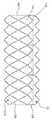
도 1a는 인공 심장 판막의 실시형태에 대한 측면도이며;
도 1b는 축 X 주위에서 부분적으로 회전되는 도 1a의 인공 심장 판막의 실시형태에 대한 측면도이고;
도 1c는 도 1a의 인공 심장 판막의 실시형태에 대한 투시도이며;
도 1d는 확장 구성의 인공 심장 판막의 도면이고;
도 1e는 압축 구성의 인공 심장 판막의 압축 도면이며;
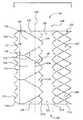
도 2a는 평편한 배향으로 펼친 도 1a의 인공 심장 판막의 실시형태에 대한 도면이고;
도 2b는 평편한 배향으로 펼친 도 1a의 인공 심장 판막의 실시형태에 대한 분해도이며;
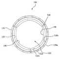
도 3a는 개방 구성의 도 1a의 인공 심장 판막의 실시형태에 대한 축방향도 또는 상면도이고;
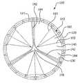
도 3b는 폐쇄 구성의 도 1a의 인공 심장 판막의 실시형태에 대한 방향도 또는 상면도이며;
도 4a는 생체 구조 내 경카테터 전달 시스템의 실시형태에 대한 측면도이고;
도 4b는 생체 구조 내 외과용 인공 심장 판막의 실시형태에 대한 측면도이며;
도 5a는 일 실시형태에 따라 제조 중인 판막의 단면도이고;
도 5b는 도 5a의 실시형태에 따라, 함께 네스팅되는 첨판 프레임과 외부 프레임의 단면도이며;
도 6a는 평편한 배향으로 펼친 외부 프레임의 실시형태이고;
도 6b는 평편한 배향으로 펼친 외부 프레임의 실시형태이며;
도 7a는 평편한 배향으로 펼친 첨판 프레임의 실시형태이고;
도 7b는 평편한 배향으로 펼친 첨판 프레임의 실시형태이며;
도 8a는 평편한 배향으로 펼친 첨판 프레임의 실시형태이고;
도 8b는 평편한 배향으로 펼친 첨판 프레임의 실시형태이며;
도 8c는 평편한 배향으로 펼친 첨판 프레임의 실시형태이고;
도 8d는 평편한 배향으로 펼친 첨판 프레임의 실시형태이며;
도 8e는 평편한 배향으로 펼친 첨판 프레임의 실시형태이고;
도 8f는 평편한 배향으로 펼친 첨판 프레임의 실시형태이며;
도 9a는 일 실시형태에 따라, 어셈블리 맨드릴 위 첨판 프레임과 외부 프레임의 측면도이고;
도 9b는 도 9a의 실시형태에 따라, 어셈블리 맨드릴 위에 함께 네스팅되는 첨판 프레임과 외부 프레임의 측면도이며;
도 10a는 또 다른 실시형태에 따라, 기계적 맞물림 부재에 의해 결합할 수 있는 첨판 프레임과 외부 프레임의 분해 측면도이고;
도 10b는 도 10a의 조립된 실시형태의 측면도이며;
도 11a는 인공 심장 판막의 실시형태에 대한 측면도이고;
도 11b는 도 11a의 인공 심장 판막의 실시형태에 대한 투시도이며;
도 11c는 개방 구성의 도 11a의 인공 심장 판막의 실시형태에 대한 축방향도 또는 상면도이고;
도 11d는 폐쇄 구성의 도 11a의 인공 심장 판막의 실시형태에 대한 축방향도 또는 상면도이며;
도 12는 도 11a 및 11b의 실시형태에 따라, 어셈블리 맨드릴 위 첨판 프레임의 측면도이고;
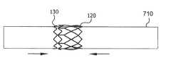
도 13a는 일 실시형태에 따라, 절삭 맨드릴 위 첨판 프레임의 측면도이며;
도 13b는 도 13a의 절삭 맨드릴 위 첨판 프레임의 투시도이다.BRIEF DESCRIPTION OF THE DRAWINGS The accompanying drawings are included to provide a further understanding of the subject matter, and are incorporated in and constitute a part of this specification, illustrate the embodiments described herein, and together with the description, It serves to explain.
1A is a side view of an embodiment of an artificial heart valve;
1B is a side view of an embodiment of the artificial heart valve of FIG. 1A partially rotated around axis X; FIG.
FIG. 1C is a perspective view of an embodiment of a prosthetic heart valve of FIG. 1A; FIG.
1D is a view of an artificial heart valve of an expanded configuration;
Figure 1e is a compaction view of a prosthetic heart valve in a compressed configuration;
Figure 2a is a view of an embodiment of the artificial heart valve of Figure la laid out in a flat orientation;
Figure 2b is an exploded view of an embodiment of the artificial heart valve of Figure la laid out in a flat orientation;
Figure 3a is an axial or top view of an embodiment of the artificial heart valve of Figure la of an open configuration;
Figure 3b is a directional or top view of an embodiment of the prosthetic heart valve of Figure 1a of a closed configuration;
4A is a side view of an embodiment of an in-vivo catheter delivery system;
4b is a side view of an embodiment of a biostructural in-patient heart valve;
5A is a cross-sectional view of a valve membrane being manufactured according to one embodiment;
Figure 5b is a cross-sectional view of a staple frame and an outer frame nested together according to the embodiment of Figure 5a;
Figure 6a is an embodiment of an outer frame laid out in a flat orientation;
Figure 6b is an embodiment of an outer frame spread out in a flat orientation;
Figure 7a is an embodiment of a prism frame laid out in a flat orientation;
Fig. 7b is an embodiment of a prism frame laid out in a flat orientation;
8A is an embodiment of a prism frame laid out in a flat orientation;
Fig. 8b is an embodiment of a prism frame laid out in a flat orientation;
Fig. 8c is an embodiment of a prism frame laid out in a flat orientation; Fig.
Figure 8d is an embodiment of a prism frame laid out in a flat orientation;
Figure 8e is an embodiment of a prism frame laid out in a flat orientation;
Figure 8f is an embodiment of a prism frame laid out in a flat orientation;
FIG. 9A is a side view of the assembly mandrel overboard frame and outer frame, in accordance with one embodiment; FIG.
Figure 9b is a side view of a stern frame and an outer frame nested together on the assembly mandrel, according to the embodiment of Figure 9a;
10A is an exploded side view of a stern frame and an outer frame that can be engaged by a mechanical engagement member, according to yet another embodiment;
Figure 10b is a side view of the assembled embodiment of Figure 10a;
11A is a side view of an embodiment of an artificial heart valve;
FIG. 11B is a perspective view of an embodiment of the prosthetic heart valve of FIG. 11A; FIG.
11C is an axial or top view of an embodiment of the artificial heart valve of Fig. 11A of an open configuration; Fig.
11D is an axial or top view of an embodiment of the prosthetic heart valve of Fig. 11A in a closed configuration; Fig.
Figure 12 is a side view of a ply frame over an assembly mandrel, in accordance with the embodiment of Figures 11A and 11B;
Figure 13A is a side view of a cutting mandrel overboard frame, in accordance with one embodiment;
Fig. 13B is a perspective view of the cutting mandrel overboard frame of Fig. 13A.
당업자는 본 개시 내용의 다양한 양태가 의도된 기능을 수행하도록 구성된 여러 가지의 방법 및 장치에 의해 실현될 수 있다는 것을 쉽게 확인할 것이다. 다르게 언급하자면, 다른 방법과 장치가 의도된 기능을 수행하도록 본원에서 일체화될 수 있다. 또한 본원에서 언급된 첨부 도면은 반드시 일정한 비율로 그려지지는 않지만, 본 개시 내용의 다양한 양태를 예시하기 위해 과장될 수 있다는 사실에 주의해야 하며, 이에 관해, 도면은 제한으로서 해석되지는 않는다.Those skilled in the art will readily appreciate that the various aspects of the present disclosure may be realized by various methods and apparatuses configured to perform the intended function. In other instances, other methods and apparatus may be incorporated herein to perform the intended function. It should also be noted that the accompanying drawings referred to herein are not necessarily drawn to scale, but may be exaggerated to illustrate various aspects of the disclosure, and the drawings are not to be construed as limitations thereof.
본원에서 실시형태가 다양한 원리 및 확신과 관련하여 기재될 수 있지만, 기재한 실시형태는 이론에 의해 제약되지는 않는다. 예를 들어, 실시형태가 본원에서 인공 심장 판막, 더 구체적으로는 심장병의 인공 심장 판막에 관해 기재된다. 그러나 본 개시 내용의 범위 내에서 실시형태는 임의의 심장 판막 또는 유사 구조의 메커니즘 및/또는 기능에 적용될 수 있다. 또한, 본 개시 내용의 범위 내에서 실시형태는 비심장병 응용 분야에 적용될 수 있다.Although the embodiments herein may be described in connection with various principles and assurances, the described embodiments are not limited by theory. For example, embodiments are described herein with respect to artificial heart valves, and more specifically, artificial heart valves of heart disease. However, within the scope of the present disclosure, embodiments may be applied to any heart valve or similar mechanism mechanism and / or function. Also, within the scope of this disclosure, embodiments can be applied to non-cardiac applications.
인공 심장 판막의 문맥에서, 본원에서 사용되는 바와 같이, 용어 첨판은 일방향 판막의 구성 요소이며, 여기서 첨판은 압력 차의 영향 하에 개폐 위치 사이에 이동하도록 조작가능하다. 개방 위치에서, 첨판은 혈액이 인공 심장 판막을 통해 흐르게 한다. 폐쇄 위치에서, 첨판은 실질적으로 인공 심장 판막을 통해 역류하는 것을 차단한다. 다중 첨판을 포함하는 실시형태에서, 각 첨판은 하나 이상의 인접 첨판과 공동으로 혈액의 역류를 차단한다. 혈액에서 압력 차는 예를 들어 심장의 심실 또는 심방의 수축에 의해 야기되며, 이러한 압력 차는 전형적으로 폐쇄될 때 첨판의 한 측면에 유체 압력 축적을 초래한다. 인공 심장 판막의 유입 측에서 압력이 인공 심장 판막의 유출 측에서 압력을 넘어서 상승할 때, 첨판이 열리고, 혈액은 이들 통해 흐른다. 혈액이 인공 심장 판막을 통해 인접 챔버 또는 혈관으로 흐를 때, 유입 측에서 압력은 유출 측에서 압력과 같아진다. 인공 심장 판막의 유출 측에서 압력이 인공 심장 판막의 유입 측에서 혈액 압력을 넘어서 상승할 때, 첨판은 폐쇄 위치로 복귀하여, 일반적으로 인공 심장 판막을 통한 혈액의 역류를 방지한다.In the context of an artificial heart valve, as used herein, the term plunger is a component of a one-way valve, wherein the plunger is operable to move between open and closed positions under the influence of a pressure differential. In the open position, the tip allows blood to flow through the artificial heart valve. In the closed position, the pivot block substantially prevents backflow through the artificial heart valve. In embodiments involving multiple plumes, each pledget blocks reflux of blood in association with one or more proximal plumes. Pressure differentials in the blood are caused, for example, by contraction of the ventricles or atria of the heart, which typically results in fluid pressure buildup on one side of the cusp when closed. When the pressure at the inflow side of the artificial heart valve rises above the pressure at the outflow side of the artificial heart valve, the skin opens and blood flows through them. When blood flows through an artificial heart valve into an adjacent chamber or blood vessel, the pressure at the inflow side equals the pressure at the outflow side. When the pressure at the outlet side of the prosthetic heart valve rises above the blood pressure at the inflow side of the prosthetic heart valve, the tip returns to its closed position and generally prevents backflow of blood through the prosthetic heart valve.
본원에서 사용되는 바와 같이, 용어 막(membrane)은 예컨대 발포 불소중합체, 그러나 이에 한정되지 않는 단일 조성물을 포함하는 물질의 시트를 의미한다.As used herein, the term membrane refers to a sheet of material including, for example, a foamed fluoropolymer, but not limited to a single composition.
본원에서 사용되는 바와 같이, 용어 복합 재료는 예컨대 발포 불소중합체, 그러나 이에 한정되지 않는 막, 및 예컨대 플루오로엘라스토머, 그러나 이에 한정되지 않는 엘라스토머의 조합을 의미한다. 엘라스토머는 막의 다공성 구조 내에 흡수되거나, 막의 한 면 또는 양면에 코팅되거나, 막에 코팅과 막 내 흡수의 조합일 수 있다.As used herein, the term composite refers to a combination of, for example, a foamed fluoropolymer, but not limited thereto, and an elastomer such as, but not limited to, a fluoroelastomer. The elastomer may be absorbed within the porous structure of the membrane, coated on one or both sides of the membrane, or a combination of coating and membrane absorption.
본원에서 사용되는 바와 같이, 용어 적층체는 막, 복합 재료, 또는 다른 물질, 예컨대 엘라스토머, 및 이들의 조합의 다수 층을 의미한다.As used herein, the term laminate refers to multiple layers of membranes, composites, or other materials such as elastomers, and combinations thereof.
본원에서 사용되는 바와 같이, 용어 필름은 총칭으로 막, 복합 재료, 또는 적층체 중 1 이상을 의미한다.As used herein, the term film generally refers to one or more of a film, a composite material, or a laminate.
용어 첨판 윈도는 첨판이 연장되는 첨판 프레임이 한정하는 공간으로서 정의된다. 첨판은 첨판 프레임 요소로부터 연장될 수 있거나, 이에 인접하고, 이로부터 이격될 수 있다.The term platoon window is defined as the space defined by the cantilever frame in which the cantilever extends. The spikes may extend from, adjacent to, and spaced from, the spine frame element.
본원에서 사용되는 바와 같이, 용어 프레임 요소는 예컨대 첨판 윈도 또는 개구를 한정하는 개별 부분, 그러나 이에 한정되지 않는, 첨판 프레임 또는 외부 프레임의 임의 부분을 의미한다.As used herein, the term frame element means any part of a lead frame or outer frame, for example, but not limited to, a septum defining a window or opening.
본원에서 사용되는 바와 같이, 용어 부착 구역은 첨판의 형상을 한정하도록 어떤 것에 부착되는 필름의 부분을 의미한다. 부착 구역은 예컨대 첨판 윈도를 한정하는 프레임 요소에 결합하는 필름의 부분일 수 있지만, 이에 한정되지 않는다. 부착 구역은 또한 예컨대 프레임 요소에 바로 인접하지 않는 위치에서 또 다른 필름에 결합하는 필름의 부분일 수 있지만, 이에 한정되지 않는다.As used herein, the term attachment region refers to the portion of the film that is attached to something to define the shape of the tab. The attachment region may be, but is not limited to, a portion of a film that engages a frame element that defines a leaf window, for example. The attachment region may also be, but is not limited to, a portion of a film that bonds to another film, for example, at a location not immediately adjacent to the frame element.
용어 천연 심장 판막 오리피스 및 조직 오리피스는 인공 심장 판막이 위치할 수 있는 해부 구조를 의미한다. 이러한 해부 구조는 심장병 판막이 수술로 제거될 수 있었거나 제거될 수 없었던 위치를 포함하나, 이에 한정되지 않는다. 인공 심장 판막을 수용할 수 있는 다른 해부 구조는 당연히 정맥, 동맥, 도관 및 션트(shunt)를 포함하나, 이에 한정되지 않는다. 본원에서 천연 심장 판막을 인공 심장 판막으로 교체하는 것을 참조하지만, 당연히 판막 오리피스 또는 이식 부위는 또한 특정 목적상 판막을 수용할 수 있는 합성 또는 생물 도관의 위치를 의미할 수 있으며, 따라서 본원에서 제공되는 실시형태의 범위는 심장 판막 교체에 한정되지 않는다.The term natural heart valve orifice and tissue orifice refers to anatomical structures in which artificial heart valves can be located. Such anatomical structures include, but are not limited to, locations where heart valves could or could not be surgically removed. Other anatomical structures that can accommodate artificial heart valves include, but are not limited to, veins, arteries, conduits, and shunts. Although reference is made herein to replacing a natural heart valve with a prosthetic heart valve, it should be appreciated that the valve orifice or implantation site may also refer to the location of a synthetic or biological conduit that is capable of receiving a valve for a particular purpose, The scope of the embodiment is not limited to heart valve replacement.
본원에서 사용되는 바와 같이, "결합"은 직접으로 또는 간접으로든지, 및 영구적으로 또는 일시적으로든지. 결합, 연결, 부착, 접착, 첩부, 또는 접합을 의미한다.As used herein, "bond" means either directly or indirectly, and either permanently or temporarily. Joining, connecting, attaching, gluing, attaching, or bonding.
본원에서 실시형태는 예컨대 심장병 판막 교체, 그러나 이에 한정되지 않는, 외과 및 경카테터 배치에 적합한 인공 심장 판막을 위한 다양한 장치, 시스템, 및 방법을 포함한다. 인공 심장 판막은 일방향 판막으로서 조작가능하며, 여기서 인공 심장 판막은 첨판이 열려 흐르게 하며, 판막 오리피스를 폐색하도록 닫히고, 유체 압력 차에 따라 플로를 막는 판막 오리피스를 한정한다.Embodiments herein include various devices, systems, and methods for artificial heart valves suitable for surgical and light catheter placement, including, but not limited to, heart valve replacement, for example. The artificial heart valve can be manipulated as a one-way valve, where the artificial heart valve opens to open the valve, closes the valve orifice, and defines a valve orifice that blocks the flow according to fluid pressure differential.
본원에서 제공되는 실시형태는 제어된 첨판 열림에 관한 것이다. 인공 심장 판막 첨판의 내구성은 개폐 사이클 동안 첨판에 의해 나타낸 굽힘 특성에 의해 주로 제어된다. 작은 반경의 굽힘, 주름 및 특히 교차 주름은 첨판에 고 응력 구역을 생성할 수 있다. 이들 고 응력 구역은 반복적인 하중 동안 구멍과 갈라진 부분의 형성을 야기할 수 있다.Embodiments provided herein relate to controlled tether opening. The durability of the artificial heart valve leaflets is mainly controlled by the bending properties exhibited by the blade during the opening and closing cycle. Bending of small radii, wrinkles and especially crossing wrinkles can create high stress areas on the tip. These high stress zones can cause the formation of holes and cracks during repeated loading.
제어된 굽힘은 얇은, 고 탄성 첨판에서 특히 중요하며, 그 이유는 이들 물질에서 굽힘은 셀로판과 유사한 경향이 있기 때문이다. 첨판 굽힘 특성이 제어되지 않으면, 주름이 형성될 뿐만 아니라, 주름 교차점은 굽힘을 방해하고, 개폐 둘 다에서 첨판 동작을 느리게 하는 큰 3차원 구조체의 형성을 유발한다: 이를 피하기 위해, 첨판 부품의 개방 순서가 제어되어야 한다.Controlled bending is particularly important in thin, high-resilient plates because bending in these materials tends to be similar to cellophane. If the tip bending characteristics are not controlled, not only the wrinkles are formed but also the wrinkle intersection hinders the bending and leads to the formation of a large three-dimensional structure which slows the tip motion in both opening and closing: To avoid this, The order should be controlled.
제어된 굽힘은 실시형태에 따라, 특정 프레임 형상을 통해 달성된다. 프레임 형상은 첨판 부착 주변에 영향을 주며, 추가로 첨판 이동에 영향을 준다.Controlled bending is achieved through a specific frame shape, according to an embodiment. The shape of the frame affects the periphery of the attachment of the flap and additionally affects the movement of the flap.
본원에서 제공되는 실시형태는 기계 및 생물 성능 장점에 관련되지만, 이들에 한정되지 않는 인공 심장 판막 기술에서의 발전을 나타낸다. 본원에서 제시하는 일부 실시형태에 따라, 인공 심장 판막은 인접 필름에 의해 함께 결합하는 2개의 프레임, 첨판 프레임 및 외부 프레임을 포함하며, 첨판 프레임은 외부 프레임에 텔레스코핑 방식으로 네스팅되며, 인공 심장 판막이 첨판 프레임과 외부 프레임 사이에서 샐 가능성이 전혀 없다.Embodiments provided herein are indicative of advances in artificial heart valve technology that are related to, but not limited to, mechanical and biological performance advantages. According to some embodiments presented herein, an artificial heart valve comprises two frames, a stern frame and an outer frame, joined together by an adjacent film, the stern frame being nested in an outer frame in a telescoping manner, There is no chance that the valve will leak between the stern frame and the outer frame.
본원에서 제시하는 일부 실시형태에 따라, 인공 심장 판막은 2개의 프레임; 첨판 프레임과 외부 프레임을 포함한다. 첨판을 포함하는 필름은 첨판 프레임의 내부 표면에 결합할 수 있다. 일부 다른 실시형태에서, 첨판을 포함하는 필름은 첨판 프레임과 외부 프레임 사이에 포함되며, 첨판 프레임에 의해 한정되는 첨판 윈도를 통해 연장된다. 따라서 첨판은 첨판이 단지 첨판 프레임의 내부 표면에 결합하는 경우와 비교하여, 첨판이 첨판 프레임과 외부 프레임 사이에 포함되기 때문에 벗겨짐 또는 탈적층화가 상당히 방지된다.According to some embodiments presented herein, an artificial heart valve comprises two frames; It includes a lead frame and an outer frame. The film containing the spikes can be bonded to the inner surface of the spikelet frame. In some other embodiments, the film comprising the tip is contained between the tip frame and the outer frame and extends through a tip window defined by the tip frame. Thus, compared to the case where the plate is only bonded to the inner surface of the plate frame, peeling or de-lamination is considerably prevented since the plate is contained between the plate frame and the outer frame.
본원에서 제시하는 일부 실시형태에 따라, 인공 심장 판막은 2개의 프레임; 첨판 프레임과 외부 프레임을 포함한다. 첨판 프레임과 외부 프레임은 서로 필름에 의해 분리된다. 환언하면, 금속 대 중합체 대 금속 상호연결이 존재하며, 첨판 프레임과 외부 프레임 사이에 금속 대 금속 접점은 없다.According to some embodiments presented herein, an artificial heart valve comprises two frames; It includes a lead frame and an outer frame. The leaf frame and the outer frame are separated from each other by a film. In other words, there is a metal-to-polymer-to-metal interconnect, and there is no metal-to-metal contact between the lead frame and the outer frame.
본원에서 제시하는 일부 실시형태에 따라, 인공 심장 판막은 2개의 프레임; 첨판 프레임과 외부 프레임을 포함한다. 첨판 프레임은 외부 프레임 내에 네스팅되며, 여기서 첨판 프레임과 외부 프레임은 공동으로 특히 평판 압축에 대해 비교적 높은 저항성을 제공한다. 일부 실시형태에 따라, 외부 프레임은 첨판 윈도 위에 구조 지지체를 제공하도록 첨판 프레임에 의해 한정되는 첨판 윈도를 오버레이하는 프레임 요소를 제공한다. 일부 실시형태에 따라, 외부 프레임은 이식될 때 조직이 첨판 윈도로 연장되는 것을 방지하도록 첨판 프레임에 의해 한정되는 첨판 윈도를 오버레이하는 프레임 요소를 제공한다. 일부 실시형태에 따라, 외부 프레임은 첨판 프레임에 의해 한정되는 첨판 윈도를 오버레이하고, 프레임 어셈블리가 경카테터 실시형태를 위해 균일하게 압축 및 확장될 수 있도록 공동으로 작용하는 프레임 요소를 제공한다.According to some embodiments presented herein, an artificial heart valve comprises two frames; It includes a lead frame and an outer frame. The leafboard frame is nested within the outer frame, wherein the leafboard frame and the outer frame are jointly provided with a relatively high resistance to plate compression in particular. According to some embodiments, the outer frame provides a frame element overlaying a tapered window defined by a tapered frame to provide a structural support over the tapered window. According to some embodiments, the outer frame provides a frame element overlaying a tapered window defined by a tapered frame to prevent tissue from extending into the tapered window when implanted. In accordance with some embodiments, the outer frame overlies a sagittal window defined by a sagittal frame and provides a cooperating frame element such that the frame assembly can be uniformly compressed and expanded for a light catheter embodiment.
인공 심장 판막Artificial heart valve
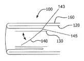
도 1a는 일 실시형태에 따라, 인공 심장 판막(100)의 측면도이다. 도 1b는 또한 종축(X) 주위로 60도 회전된 도 1a의 인공 심장 판막(100)의 측면도이다. 도 1c는 도 1a의 인공 심장 판막(100)의 투시도이다. 도 2a는 도 1a의 인공 심장 판막(100)의 측면도이며, 여기서 인공 심장 판막(100)은 길이로 잘라내고, 열려 있어서 일반적으로 관 형상의 인공 심장 판막(100)의 요소를 더 양호하게 도시하였다. 도 2b는 도 2a의 실시형태의 분해도이다. 도 3a와 3b는 각각 개방 및 폐쇄 구성의 도 1a의 인공 심장 판막(100)의 축방향도이다. 도 3b에서 첨판(140)은 약간 열려서 도시되어 피처를 더 양호하게 보여주지만, 완전히 폐쇄된 인공 심장 판막(100)은 하류 혈액이 판막을 통해 역류하는 것을 방지하도록 판막을 폐쇄하게 하는 하류 유체 압력의 영향 하에 접합하도록 합치는 첨판들(140)의 첨판 자유 에지들(142)을 가질 것이라고 이해된다.1A is a side view of an
도 11a는 일 실시형태에 따라, 인공 심장 판막(200)의 측면도이다. 도 11b는 도 1a의 인공 심장 판막(200)의 투시도이다. 인공 심장 판막(200)은 첨판 프레임(130f)과 첨판(140)을 한정하는 필름(160)을 포함한다. 도 8d는 도 11a의 인공 심장 판막(200)의 첨판 프레임(130f)에 대한 측면도이며, 여기서 첨판 프레임(130f)은 길이로 잘라내고, 열려 있어서 일반적으로 관 형상의 인공 심장 판막(200)의 요소를 더 양호하게 도시한다. 도 11b에서, 첨판(140)은 약간 열려서 도시되어 피처를 더 양호하게 보여주지만, 완전히 폐쇄된 인공 심장 판막(200)은 하류 혈액이 판막을 통해 역류하는 것을 방지하도록 판막을 폐쇄하게 하는 하류 유체 압력의 영향 하에 접합하도록 합치는 첨판들(140)의 첨판 자유 에지들(142)을 가질 것이라고 이해된다. 본원에서 사용되는 바와 같이, 용어 "프레임 요소"는 예컨대 첨판 윈도(137)를 한정하는 개별 부분들, 그러나 이에 한정되지 않는, 첨판 프레임(130)의 임의 부분을 의미한다. 첨판 프레임 제1 단부(131a)는 추가로 실질적으로 삼각형을 한정하는 첨판 프레임 요소의 정점으로부터 연장되는 접합부 기둥(commissure post)(136)을 포함한다.11A is a side view of an
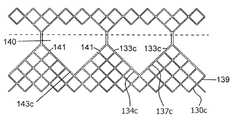
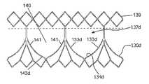
도 8d는 도 11a 및 11b의 인공 심장 판막(200)의 첨판 프레임(130f)에 대한 측면도이며, 여기서 첨판 프레임(130f)은 길이로 잘라내고, 열려 있어서 일반적으로 관 형상의 인공 심장 판막(200)의 요소를 더 양호하게 도시한다. 첨판 프레임(130f)은 이등변 사각형인 첨판 윈도(137f)를 한정하는 베이스 요소(138f)에 의해 상호연결된, 실질적으로 이등변 삼각형을 한정하는 다수의 이격된 프레임 요소(139)를 포함한다. 각 첨판 윈도 사이드(133)는 한 삼각형의 사이드와 인접 삼각형의 사이드에 의해 한정되며, 여기서 각 첨판 윈도 베이스(134)는 베이스 요소(138)에 의해 한정된다. 본원에서 사용되는 바와 같이, 용어 "프레임 요소"는 예컨대 첨판 윈도(137)를 한정하는 개별 부분, 그러나 이에 한정되지 않는, 첨판 프레임(130)의 임의 부분을 의미한다.8D is a side view of the
다시 도 11a와 8d에 관해, 첨판 프레임 제1 단부(131a)는 추가로 실질적으로 이등변 삼각형을 한정하는 첨판 프레임 요소의 정점으로부터 연장되는 접합부 기둥(136)을 포함한다. 접합부 기둥(136)은 인접 첨판 자유 에지들(142) 사이에 더 크거나 더 넓은 유착(coaptation) 영역(146)을 만들도록 첨판 자유 에지(142)에 작용할 수 있다.Again with respect to Figures 11a and 8d, the cusp frame
외부 프레임Outer frame
외부 프레임(120)은 도 1c에 도시한 바와 같이, 일 실시형태에 따라, 개구의 일반적인 개방 패턴(122)을 한정하는 일반적으로 관형 부재이다.The
경카테터 실시형태에 따라, 외부 프레임(120)은 상이한 직경 사이에서 압축되고, 확장되도록 조작가능하다. 외부 프레임(120)은 도 5a에 도시한 바와 같이, 외부 프레임 외부 표면(126a)과 외부 프레임 외부 표면(126a) 맞은편의 외부 프레임 내부 표면(126b)을 포함한다. 외부 프레임(120)은 스텐트와 같이 본 기술에서 알려진 구조를 포함할 수 있다. 스텐트는 생체 구조로 경피 경카테터 전달에 적합한 직경이 작을 수 있는 관형 부재이며, 생체 구조로 전개될 때 더 큰 직경으로 확장될 수 있다. 다양한 설계와 물질 특성을 가진 스텐트가 본 기술에서 잘 알려져 있다.According to the light catheter embodiment, the
일예로서, 그리고 도 1a-1c 및 2a-2b의 실시형태로 도시된 바와 같이, 인공 심장 판막(100)은 일반적으로 도 1d에 도시한 바와 같이, 큰 직경 구조에 있을 때 일반적으로 다이아몬드 형상인 개구(122)를 가진 스텐트를 한정하는 외부 프레임(120)을 포함한다. 더 작은 직경으로 압축 시, 개구(122)는 도 1e에 도시한 바와 같이, 일반적으로 신장된 다이아몬드 형상을 한정하도록 변형된다. 더 큰 직경으로 재확장 시, 개구(122)는 일반적으로 다이아몬드 형상을 다시 한정하도록 재확장된다.As an example, and as shown in the embodiments of Figs. 1a-1c and 2a-2b, the
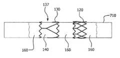
도 5a 및 5b에 도시한 바와 같이, 양 도면은 요소를 단면으로 보여주는데, 첨판 프레임(130)은 다수의 첨판 윈도(도시 안 됨)를 한정하는 일반적으로 관 형상이다. 외부 프레임(120)은 일반적으로 관 형상이다. 첨판 프레임(130)은 적어도 부분적으로 외부 프레임(120) 내에 동축으로 배치된다. 첨판 프레임(130)과 외부 프레임(120)은 필름(160)의 인접 부분에 의해 적어도 부분적으로 결합한다. 필름(160)의 인접 부분 중 적어도 일부는 사이에 포함되고, 첨판 프레임(130)을 외부 프레임(120)에 결합하여 이들 사이에서 상대 운동을 억제한다. 필름은 각 첨판 윈도로부터 연장되는 첨판(140)을 한정한다. 첨판 베이스(143)는 필름(160) 중 접힘선(fold line)(145)에서 한정된다. 일 실시형태에 따라, 사이에 포함되고, 첨판 프레임(130)과 외부 프레임(120)을 결합하는 필름(160)의 인접 부분 중 적어도 일부는 첨판 프레임(130)과 외부 프레임(120) 사이의 접촉을 방지한다.As shown in FIGS. 5A and 5B, both of the figures show the elements in cross-section, and the
도 6a와 6b는 외부 프레임(120a, 120b)의 대체 실시형태에 대한 측면도이며, 여기서 외부 프레임은 길이로 잘라내고, 열려 있어서 외부 프레임의 요소를 더 양호하게 도시한다.6A and 6B are side views of an alternative embodiment of the
스텐트의 열린 골격은 피처를 얼마든지, 반복가능하게 또는 아니면, 예컨대 기하 형상 및/또는 직선 또는 곡류의 일련의 동양혈관(sinusoid)을 한정할 수 있다. 기하 형상은 실질적으로 균일한 원주 압축과 확장을 용이하게 하는 임의 형상을 포함할 수 있다. 외부 프레임(120)은 컷 튜브(cut tube), 또는 특정 목적에 적합한 임의의 다른 요소를 포함할 수 있다. 외부 프레임(120)은 식각되거나, 잘라내거나, 레이저로 잘라내거나, 튜브 또는 물질의 시트로 찍어낼 수 있으며, 그 후 시트는 실질적으로 원통 구조로 형성될 수 있다. 대안으로, 세장 재료, 예컨대 와이어, 구부릴 수 있는 스트립, 또는 이들의 일련의 재료를 구부리거나 꼰 다음, 실질적으로 원통 구조로 형성할 수 있으며, 여기서 원통 벽은 일반적으로 균일한 원주 방식으로 더 작은 직경으로 압축가능하고, 더 큰 직경으로 확장가능한 열린 골격을 포함한다.The open skeleton of the stent can define any number of features, repeatably or otherwise, a series of sinusoids, e.g., geometric shapes and / or straight or cereal. The geometry may include any shape that facilitates substantially uniform circumferential compression and expansion. The
다양하게 설계된 스텐트는 스프링 하중 하에 자기 확장하도록 탄성적으로 변형가능할 수 있다고 알려져 있다. 또한 다양하게 설계된 스텐트는 예컨대 발룬과 함께 기계적으로 확장되도록 소성적으로 변형가능할 수 있다고 알려져 있다. 또한 다양하게 설계된 스텐트는 탄성적으로 변형가능할 뿐만 아니라 소성적으로 변경가능할 수 있다고 알려져 있다. 본원에서 제시하는 외부 프레임(120)의 실시형태는 특정 스텐트 설계 또는 확장 모드로 한정되지 않는다.Variously designed stents are known to be elastically deformable to self-expand under spring loads. It is also known that variously designed stents can be plastic deformed to expand mechanically with, for example, baluns. It is also known that variously designed stents can be resiliently deformable as well as resiliently. Embodiments of the
외부 프레임(120)은 임의의 금속 또는 중합체 생체적합성 물질을 포함할 수 있다. 예를 들어, 외부 프레임(120)은 예컨대 니티놀, 코발트 니켈 합금, 스테인리스강, 또는 폴리프로필렌, 아세틸 단독 중합체, 아세틸 공중합체, ePTFE, 다른 합금 또는 중합체, 또는 본원에서 기재한 바와 같이 작용하는 적합한 물리적 및 기계적 특성을 가진 임의의 다른 생체적합성 물질, 그러나 이들에 한정되지 않는, 물질을 포함할 수 있다.The
실시형태에 따라, 외부 프레임(120)은 인공 심장 판막(100)의 경카테터 전개를 나타내는 도 4a에 도시한 바와 같이, 이식 부위와 포지티브(positive) 맞물림을 제공하여 인공 심장 판막(100)을 부위에 단단히 고정하도록 구성될 수 있다. 일 실시형태에 따라, 외부 프레임(120)은 위치를 유지하는 조직 오리피스(150)에 대해 충분한 병렬(apposition)을 유지하도록 약간의 탄성 수축력이 있는 충분히 강성인 프레임을 포함할 수 있다. 또 다른 실시형태에 따라, 외부 프레임(120)은 조직 오리피스(150)보다 더 큰 직경으로 확장하도록 구성될 수 있어서, 인공 심장 판막(100)이 조직 오리피스(150)로 확장될 때, 이것은 내부에 견고하게 자리를 잡을 수 있다. 또 다른 실시형태에 따라, 외부 프레임(120)은 이식 부위, 예컨대 조직 오리피스(150)를 맞물려 인공 심장 판막(100)을 이식 부위에 단단히 고정하도록 구성되는 1 이상의 앵커(anchor)(도시 안 됨)를 포함할 수 있다.According to an embodiment, the
인공 심장 판막(100)을 이식 부위에 결합하기 위한 다른 요소 또는 수단이 당연히 예상된다. 일예로서, 그러나 이에 한정되지 않으며, 다른 수단, 예컨대 기계적 및 접착제 수단이 인공 심장 판막(100)을 합성 또는 생물 도관에 결합하는데 사용될 수 있다.Other elements or means for coupling the
후에 설명되는 바와 같이, 외과용 인공 심장 판막(100) 실시형태는 외과용 인공 심장 판막(100)이 고정 직경으로 될 수 있으며, 압축되고, 재확장되도록 조작가능할 필요가 없으므로 지그재그 구조일 수 있거나 아닐 수 있다.As will be described later, the surgical
첨판Crown 프레임 frame
첨판 프레임은 실시형태에 따라, 다수의 이격된 첨판 윈도를 포함한다.The spade frame includes a plurality of spaced spike windows, depending on the embodiment.
도 7a는 평편한 배향으로 펼친 첨판 프레임(130a)의 또 다른 실시형태에 대한 도면이다. 첨판 프레임(130a)은 혈관 내 배치에 필요할 압축과 확장에 영향을 주는데 적합한 프레임 요소(139)를 포함한다. 첨판 윈도(137a)는 첨판 윈도 베이스(134a)에서 만나는 2개의 첨판 윈도 사이드(133a)에 의해 한정된다. 첨판(140)을 점선으로 도시하여 첨판(140)이 첨판 윈도(137a) 내에 위치하는 곳을 나타낸다. 첨판 측면들(141)은 첨판 윈도 사이드(133a)에 결합하고, 첨판 베이스(143a)는 첨판 윈도 베이스(134a)에 결합한다. 첨판 프레임(130a)은 3개의 삼각형 첨판 윈도(137a)의 일반적으로 원통 배열로 이루어지며, 이들의 중앙은 각각 120°이격되어 있다. 도 7a의 첨판 프레임(130a)의 실시형태는 실질적으로 도 2b에 도시한 첨판 프레임(130)의 실시형태와 동일하다. 도 2b에 도시한 첨판 프레임(130)은 첨판 프레임 제1 단부(131a)와 첨판 프레임 제1 단부(131a) 맞은편의 첨판 프레임 제2 단부(131b)를 갖는다.7A is a view of another embodiment of a
도 7b는 평편한 배향으로 펼친 첨판 프레임(130b)의 또 다른 실시형태에 대한 도면이다. 첨판 윈도(137b)는, 신장되고, 판막 축과 수평인 첨판 윈도 베이스(134b)에서 만나는 2개의 첨판 윈도 사이드(133b)에 의해 한정된다. 첨판(140)을 점선으로 도시하여 첨판(140)이 첨판 윈도(137b) 내에 위치하는 곳을 나타낸다. 첨판 측면들(141)은 첨판 윈도 사이드(133b)에 결합하고, 첨판 베이스(143b)는 첨판 윈도 베이스(134b)에 결합한다. 첨판 윈도 베이스(134b)는 첨판이 개폐 중에 평편한 베이스로부터 휘어지도록 평편하다.FIG. 7B is a view of another embodiment of the
도 8a는 평편한 배향으로 펼친 첨판 프레임(130c)의 또 다른 실시형태에 대한 도면이다. 첨판 프레임(130c)은 혈관 내 배치에 필요할 압축과 확장에 영향을 주는데 적합한 프레임 요소(139)를 포함한다. 첨판 윈도(137c)는 첨판 윈도 베이스(134c)에서 만나는 2개의 첨판 윈도 사이드(133c)에 의해 한정된다. 첨판(140)을 점선으로 도시하여 첨판(140)이 첨판 윈도(137c) 내에 위치하는 곳을 나타낸다. 첨판 측면들(141)은 첨판 윈도 사이드(133c)에 결합하고, 첨판 베이스(143c)는 첨판 윈도 베이스(134c)에 결합한다.8A is a view of another embodiment of a
도 8b는 평편한 배향으로 펼친 첨판 프레임(130d)의 또 다른 실시형태에 대한 도면이다. 첨판 프레임(130d)은 혈관 내 배치에 필요할 압축과 확장에 영향을 주는데 적합한 프레임 요소(139)를 포함한다. 첨판 윈도(137d)는 첨판 윈도 베이스(134d)에서 만나는 2개의 첨판 윈도 사이드(133d)에 의해 한정된다. 첨판(140)을 점선으로 도시하여 첨판(140)이 첨판 윈도(137d) 내에 위치하는 곳을 나타낸다. 첨판 측면들(141)은 첨판 윈도 사이드(133d)에 결합하고, 첨판 베이스(143d)는 첨판 윈도 베이스(134d)에 결합한다. 첨판 윈도 사이드(133d)는 포물선 형상을 한정한다.Fig. 8B is a view of another embodiment of a
도 8c는 평편한 배향으로 펼친 첨판 프레임(130e)의 또 다른 실시형태에 대한 도면이다. 첨판 프레임(130e)은 혈관 내 배치에 필요할 압축과 확장에 영향을 주는데 적합한 프레임 요소(139)를 포함한다. 첨판 윈도(137e)는 첨판 윈도 베이스(134e)에서 만나는 2개의 첨판 윈도 사이드(133e)에 의해 한정된다. 첨판(140)을 점선으로 도시하여 첨판(140)이 첨판 윈도(137e) 내에 위치하는 곳을 나타낸다. 첨판 측면들(141)은 첨판 윈도 사이드(133e)에 결합하고, 첨판 베이스(143e)는 첨판 윈도 베이스(134e)에 결합한다.8C is a view of another embodiment of a
도 8d는 첨판 프레임(130f)의 대체 실시형태에 대한 측면도이며, 여기서 첨판 프레임(130f)은 길이로 잘라내고, 열려 있어서 실질적으로 도 11a와 11b의 인공 심장 판막(100)으로서 도시한 판막 중 첨판 프레임(130f)의 요소를 더 양호하게 도시한다. 첨판(140f)을 점선으로 도시하여 첨판(140f)이 첨판 윈도(137f) 내에 위치하는 곳을 나타내며, 첨판 윈도(137f)는 첨판 윈도 사이드(133f)과 첨판 윈도 베이스(134f)에 의해 한정된다. 2개의 첨판 측면(141f)은 도 8d에서 점선으로 도시한 바와 같이, 첨판 베이스(143f)로부터 분기하며, 여기서 첨판 베이스(143f)는 실질적으로 평편하며, 첨판 자유 에지(142f)는 첨판 베이스(143f) 맞은편에 있다. 첨판 프레임(130f)은 추가로 첨판 자유 에지(142f)가 연장되는 접합부 기둥(136)을 한정한다.Figure 8d is a side view of an alternative embodiment of a
도 8e는 첨판 프레임(130g)의 대체 실시형태에 대한 측면도이며, 여기서 첨판 프레임(130g)은 길이로 잘라내고, 열려 있어서 첨판 프레임(130g)의 요소를 더 양호하게 도시한다. 첨판(140g)을 점선으로 도시하여 첨판(140g)이 첨판 윈도(137g) 내에 위치하는 곳을 나타내며, 첨판 윈도(137g)는 첨판 윈도 사이드(133g)와 첨판 윈도 베이스(134g)에 의해 한정된다. 2개의 첨판 측면(141g)은 도 8e에서 점선으로 도시한 바와 같이, 첨판 베이스(143g)로부터 분기하며, 여기서 첨판 베이스(143g)는 실질적으로 평편하며, 첨판 자유 에지(142g)는 첨판 베이스(143g) 맞은편에 있다. 첨판 프레임(130g)은 이등변 사각형을 한정하는 첨판 윈도(137g)를 한정하는 첨판 윈도 베이스(134g)에 의해 상호연결되는 다수의 이등변 삼각형을 한정하는 다수의 첨판 프레임 요소를 포함한다. 각 첨판 윈도 사이드(133g)는 한 삼각형의 사이드와 인접 삼각형의 사이드에 의해 한정된다.8E is a side view of an alternative embodiment of the
도 8f는 첨판 프레임(130h)의 대체 실시형태에 대한 측면도이며, 여기서 첨판 프레임(130h)은 길이로 잘라내고, 열려 있어서 첨판 프레임(130h)의 요소를 더 양호하게 도시한다. 첨판 프레임(130h)은 베이스 요소(138h)와 베이스 요소(138h)에 의해 상호연결되는 다수의 이격된 스페이드 요소(170)를 포함한다. 각 첨판 윈도(137h)는 한 스페이드 요소(170)의 스페이드 측면(175)과 인접 스페이드 요소(170)의 스페이드 측면(175)에 의해 한정되며, 여기서 각 첨판 윈도 베이스(134h)는 베이스 요소(138h)에 의해 한정된다. 스페이드 측면(175)은 베이스 요소(138h)로 연장되지 않는다. 기하 구조에 의해, 첨판(140h)은 개폐 중에 스페이드 측면(175) 주위에 그리고 부착 구역(163)을 한정하는, 첨판(140)이 프레임 요소(139)에 바로 인접하게 휘어지지 않는 부분적으로 프레임이 없는 첨판 윈도(137h)를 한정하는 베이스 요소(138h) 쪽으로 휘어질 것이다. 첨판 베이스(143h)는 첨판 베이스(143h)가 베이스 요소(138h)에 바로 인접하게 휘어지지 않도록 베이스 요소(138h)로부터 떨어진 거리에 한정될 수 있다. 베이스 요소(138h)에 바로 인접하지 않는 첨판 베이스(143h)는 본원에서 가상 첨판 윈도 베이스로서 언급되며, 가상은 의미상 첨판 윈도 베이스가 프레임 요소에 의해 직접 한정되지 않는다. 인공 심장 판막의 실시형태에 따라, 각 첨판(140h)은 2개의 첨판 측면(141h), 첨판 베이스(143h) 및 첨판 베이스(143h) 맞은편의 첨판 자유 에지(142h)를 가진 이등변 사각형 형상의 형태를 실질적으로 취하며, 여기서 2개의 첨판 측면(141h)은 도 8f에서 점선으로 도시한 바와 같이, 첨판 베이스(143h)로부터 분기하며, 첨판 베이스(143h)는 실질적으로 평편하다.Fig. 8f is a side view of an alternative embodiment of the
실질적으로 도 8f에 도시한 또 다른 실시형태에서, 필름 제1 층(160a)은 첨판 프레임(130h)의 첨판 프레임 내부 표면(132b)에 결합하고, 필름 제2 층(160b)은 첨판 프레임 내부 표면(132b)으로부터 맞은편 첨판 프레임(130h)의 첨판 프레임 외부 표면(132a)에 결합한다. 필름 제1 층(160a)과 필름 제2 층(160b)을 함께 결합하여 부착 구역(163)을 한정한다.8F, the film
이전에 논의한 바와 같이, 첨판 윈도 베이스는 실시형태에 따라 첨판 베이스(143)를 한정하는데 사용될 수 있다. 또한 이전에 논의한 바와 같이, 첨판 베이스(143)는 도 1a, 1b 및 2b에 도시한 바와 같이, 첨판 윈도 베이스(134)로부터 이격된 접힘 영역(144)에서 필름(160) 중 접힘선(145)에 의해 가상 첨판 베이스(143a)로서 정의될 수 있다. 특정 목적에 적합한 구조를 가진 외부 프레임에 대해 당연히 많은 실시형태가 존재한다.As discussed previously, the pointed window base can be used to define the pointed
도 10a는 또 다른 실시형태에 따라 기계적 맞물림 부재(1110)에 의해 결합하는 일반적인 관 형상을 갖는 첨판 프레임(1130)과 일반적인 관 형상을 갖는 외부 프레임(1120)을 포함하는 또 다른 인공 심장 판막의 분해 측면도이다. 도 10b는 도 10a의 실시형태에 대한 조립도이다.FIG. 10A is a perspective view of another artificial heart valve comprising a
이전에 논의한 바와 같이, 첨판 윈도 베이스는 실시형태에 따라 첨판 베이스를 한정하는데 사용될 수 있다. 또한 이전에 논의한 바와 같이, 첨판 베이스는 도 1b 및 2b에 도시한 바와 같이, 첨판 윈도 베이스로부터 이격된 접힘 영역(144)에서 필름(160) 중 접힘선(145)에 의해 가상 첨판 베이스(143a)로서 정의될 수 있다. 특정 목적에 적합한 구조를 가진 외부 프레임에 대해 당연히 많은 실시형태가 존재한다.As discussed previously, a pointed window base can be used to define a pointed base in accordance with an embodiment. As also discussed previously, the base plate may have a
경카테터 인공 심장 판막(100) 실시형태에서, 첨판 프레임(130)은 경피 경카테터 고정 및 전달을 수용하는 비교적 작은 직경을 얻도록 탄성적으로, 소성적으로, 또는 둘 다로 압축가능하다.In a catheter
일 실시형태에 따라, 첨판 프레임(130)과 외부 프레임(120)은 하중 하에 휘고, 하중이 제거될 때 처음 형상으로 복원되도록 조작가능한 형상 기억 물질을 포함하며, 따라서 첨판 프레임(130)과 외부 프레임(120)이 압축 형상에서 소정 형상으로 자기 확장하게 한다. 일 실시형태에 따라 첨판 프레임(130)은 발룬에 의해 확장되도록 소성적으로 변형가능하다. 또 다른 실시형태에서, 외부 프레임(120)은 자기 확장하도록 탄성적으로 변형가능하다.According to one embodiment, the
필름film
필름(160)은 실시형태에 따라, 생물학적으로 적합하며, 첨판에 첨판 프레임까지 결합하도록 구성되는 임의의 시트류 재료이다. 용어 "필름"이 특정 목적에 적합한 1 이상의 생체적합성 물질에 대해 총칭으로 사용된다고 이해된다. 첨판(140)은 또한 필름(160)으로 이루어진다.The
일 실시형태에 따라, 생체적합성 물질은 생물 원이 아니고, 생체적합성 중합체와 같이, 특정 목적을 위해 충분히 유연하고, 강한 필름(160)이다. 일 실시형태에서, 필름(160)은 복합체로서 언급된, 엘라스토머와 배합되는 생체적합성 중합체를 포함한다.According to one embodiment, the biocompatible material is not a biogenic source, and is a
다양한 형태의 필름(160)에 대한 세부 내용은 하기에 설명된다. 일 실시형태에서, 필름(160)은 적어도 부분적으로 외부 프레임(120)과 첨판 프레임(130)을 덮는 일반적으로 관형 재료로부터 형성될 수 있다. 필름(160)은 막, 복합 재료, 또는 적층체 중 1 이상을 포함할 수 있다. 다양한 형태의 필름(160)에 대한 세부 내용은 하기에 설명된다.Details of the various types of
첨판Crown
각 첨판 윈도(137)에 생체적합성 물질, 예컨대 필름(160)이 제공되며, 이는 첨판 윈도 사이드(133)의 일부에 결합하고, 필름(160)은 첨판(140)을 한정한다. 각 첨판(140)은 일 실시형태에 따라, 첨판 자유 에지(142)와 첨판 베이스(143)를 한정한다. 하기에 기재되는 바와 같이, 첨판 베이스 구조에 대한 다수 실시형태가 제공될 수 있다고 예상된다. 일 실시형태에 따라, 필름(160)은 첨판 윈도 사이드(133)의 부분에 그리고 첨판 윈도 베이스(134)에 결합하고, 여기서 첨판(140)은 첨판 윈도 사이드(133)의 부분과 첨판 윈도 베이스(134)에 의해 한정된다. 또 다른 실시형태에 따라, 필름(160)은 첨판 윈도 사이드의 부분에 결합한다.A biocompatible material, such as a
첨판(140)의 형상은 첨판 윈도(137)와 첨판 자유 에지(142)의 형상에 의해 부분적으로 한정된다. 일 실시형태에 따라 하기에 논의되는 바와 같이, 첨판(140)의 형상은 또한 첨판(140)에 소정의 형상을 부여하도록, 하기에 추가로 기재될 가상 첨판 베이스(143a)를 한정하는 접힘선(145)에서 접힘을 유도하는 공정에 부분적으로 좌우된다. 높은 굽힘 응력이 첨판 베이스에 위치하므로, 첨판 윈도 베이스(134)에 의해 속박되지 않는 가상 첨판 베이스(143a)를 한정하여 첨판 베이스(143) - 첨판 윈도 베이스(134) 인터페이스에서 첨판(140)의 갈라지는 가능성을 줄일 수 있다. 이것은 또한 둥근 첨판 베이스와 비교하여 첨판 베이스에서 혈액 저류 및 정체를 줄일 수 있다.The shape of the
첨판(140)이 완전 개방 위치에 있을 때, 인공 심장 판막(100)은 도 3a에 도시한 바와 같이 실질적으로 원형 판막 오리피스(102)를 나타낸다. 첨판(140)이 개방 위치에 있을 때 판막 오리피스(102)를 통해 유체 흐름이 허용된다.When the
첨판(140)이 개폐 위치 사이에서 순환할 때, 첨판(140)은 일반적으로 첨판이 결합하는 첨판 윈도 사이드(133)의 부분 및 첨판 베이스(143) 주위에 구부러진다. 인공 심장 판막(100)이 폐쇄될 때, 도 3b에 도시한 바와 같이, 일반적으로 각 첨판 자유 에지(142)의 약 반이 인접 첨판(140)의 첨판 자유 에지(142)의 인접한 반에 접해 있다. 도 3b의 실시형태 중 3개의 첨판(140)은 삼중점(148)에서 만난다. 판막 오리피스(102)는 첨판(140)이 유체 흐름을 중단하는 폐쇄 위치에 있을 때 폐색된다.When the
도 3b에 관해, 일 실시형태에 따라, 각 첨판(140)은 중앙 영역(182)과 이 중앙 영역(182)의 양측에 있는 2개의 측면 영역(184)을 포함한다. 중앙 영역(182)은 2개의 중앙 영역 측면(183), 첨판 베이스(143) 및 첨판 자유 에지(142)에 의해 한정된 실질적인 이등변 삼각형 형상에 의해 한정된다. 2개의 중앙 영역 측면(183)은 첨판 베이스(143)로부터 첨판 자유 에지(142)로 모인다. 측면 영역(184)은 각각 실질적으로 삼각형 형상이며, 각각 중앙 영역 측면(183) 중 하나, 첨판 측면(141) 중 하나, 및 첨판 자유 에지(142)에 의해 한정된다.3B, in accordance with one embodiment, each
일 실시형태에 따라, 2개의 측면 영역(184)과 중앙 영역(182)은 각각 인공 심장 판막(100)이 폐쇄 위치에 있을 때 실질적으로 평면이다.According to one embodiment, the two
첨판(140)은 예를 들어 심장의 심실 또는 심방의 수축에 의해 야기된 혈액의 압력 차에서 동작하도록 구성될 수 있으며, 이러한 압력 차는 전형적으로 폐쇄될 때 인공 심장 판막(100)의 한 측면에 유체 압력 축적을 초래한다. 인공 심장 판막(100)의 유입 측 위 압력이 인공 심장 판막(100)의 유출 측 위 압력보다 상승할 때, 첨판(140)이 열리고, 혈액은 이를 통해 흐른다. 혈액이 인공 심장 판막(100)을 통해 인접 챔버 또는 혈관으로 흐를 때, 압력은 같아진다. 인공 심장 판막(100)의 유출 측 위 압력이 인공 심장 판막(100)의 유입 측 위 혈액 압력보다 상승할 때, 첨판(140)은 폐쇄 위치로 복귀하여 일반적으로 인공 심장 판막(100)의 유입 측을 통한 혈액의 역류를 방지한다.The
첨판 프레임(130)은 실시형태에 따라, 특정 목적에 적합한, 다수의 첨판 윈도(137), 및 따라서 첨판들(140)을 포함할 수 있다고 이해된다. 1, 2, 3개 이상의 첨판 윈도(137) 및 상응하는 첨판(140)을 포함하는 첨판 프레임(130)이 예상된다.It is understood that the
경카테터 인공 심장 판막(100)의 실시형태에 따라, 도 1d-1e에 관해, 인공 심장 판막(100)은 더 작은 직경을 가진 축소 구성으로 압축될 수 있고, 확장 구성으로 확장될 수 있어서, 인공 심장 판막(100)이 카테터를 통해 축소 구성으로 전달될 수 있으며, 도 4a에 도시한 바와 같이 조직 오리피스(150) 내에 전개 시 확장될 수 있다. 외부 프레임(120)은 축소 구성으로부터 확장 구성으로 이행될 때 원주 균일성을 회복하도록 조작가능할 수 있다.1D-1E,
인공 심장 판막(100)은 특정 목적에 적합한 전달 카테터에 고정될 수 있다. 인공 심장 판막(100)의 직경은 축소 구성으로 첨판 프레임의 두께와 첨판 두께에 의해 부분적으로 결정된다.The
첨판Crown 필름 film
첨판(140)을 구성하는 생체적합성 물질은 임의의 생물 조직 또는 충분히 적합하고, 유연한, 합성, 생체적합성 물질, 예컨대 생체적합성 중합체를 포함할 수 있다. 일 실시형태에서, 첨판(140)은 복합체로서 지칭되는, 엘라스토머와 배합되는 생체적합성 중합체를 포함한다. 일 실시형태에 따른 물질은 피브릴(fibril)의 매트릭스 내에 다수의 공간을 포함하는 발포 불소중합체 막, 및 엘라스토머 물질을 포함하는 복합 재료를 포함한다. 당연히 본 개시 내용의 범위 내에 속하면서 다수 형태의 불소중합체 막과 다수 형태의 엘라스토머 물질이 배합되어 적층체를 형성할 수 있다. 또한 본 개시 내용의 범위 내에 속하면서 엘라스토머 물질은 당연히 다수 엘라스토머, 다수 형태의 비엘라스토머 성분, 예컨대 무기 충전제, 치료제, 방사선 불투과 표지자, 등을 포함할 수 있다.The biocompatible material that constitutes the
일 실시형태에 따라, 복합 재료는 예를 들어 바시노(Bacino)의 미국특허 제7,306,729호에 일반적으로 기재되어 있는 바와 같이, 다공성 ePTFE 막으로부터 제조된 발포 불소중합체 물질을 포함한다.According to one embodiment, the composite material comprises a foamed fluoropolymer material made from a porous ePTFE membrane, for example, as generally described in U.S. Patent No. 7,306,729 to Bacino.
기재한 발포 불소중합체 물질을 형성하는데 사용되는 발포성 불소중합체는 PTFE 단독 중합체를 포함할 수 있다. 대체 실시형태에서, PTFE, 발포성 개질 PTFE 및/또는 PTFE의 발포 공중합체의 블렌드가 사용될 수 있다. 적합한 불소중합체 물질의 비제한적인 일예는 예를 들어 브란카(Branca)의 미국특허 제5,708,044호, 베일리(Baillie)의 미국특허 제6,541,589호, 사볼(Sabol) 외 그의 공동발명자의 미국특허 제7,531,611호, 포드(Ford)의 미국특허 출원 제11/906,877호, 쉬(Xu) 외 그의 공동발명자의 미국특허 출원 제12/410,050호에 기재되어 있다.The expandable fluoropolymer used to form the described foamed fluoropolymer material may comprise a PTFE homopolymer. In alternative embodiments, a blend of expanded copolymers of PTFE, expandable modified PTFE and / or PTFE may be used. Non-limiting examples of suitable fluoropolymer materials are described, for example, in U.S. Patent No. 5,708,044 to Branca, U.S. Patent No. 6,541,589 to Baillie, U.S. Patent No. 7,531,611 to Sabol et al. , U.S. Patent Application No. 11 / 906,877 to Ford, and U.S. Patent Application No. 12 / 410,050 to Xu et al.
발포 불소중합체 막은 원하는 첨판 성능을 달성하기 위해 임의의 적합한 미세구조를 포함할 수 있다. 일 실시형태에 따라, 발포 불소중합체는 예컨대 고어(Gore)의 미국특허 제3,953,566호에 기재된, 피브릴에 의해 상호연결되는 노드(node)의 미세구조를 포함한다. 피브릴은 다수의 방향으로 노드로부터 방사상으로 연장되며, 막은 일반적으로 균질 구조를 갖는다. 이러한 미세구조를 가진 막은 전형적으로 2 미만, 및 가능하게는 1.5 미만의 2 직교 방향에서 매트릭스 인장 강도 비를 나타낼 수 있다.The foamed fluoropolymer film may comprise any suitable microstructure to achieve the desired foil performance. According to one embodiment, the foamed fluoropolymer includes the microstructure of a node interconnected by a fibril, such as described in US Pat. No. 3,953,566 to Gore. The fibrils extend radially from the nodes in a number of directions, and the films generally have a homogeneous structure. Films with such microstructures can exhibit a matrix tensile strength ratio in two orthogonal directions, typically less than 2, and possibly less than 1.5.
또 다른 실시형태에서, 발포 불소중합체 막은 바시노의 미국특허 제7,306,729호가 일반적으로 교시하는 바와 같이, 실질적으로 피브릴만의 미세구조를 갖는다. 실질적으로 피브릴만을 가진 발포 불소중합체 막은 높은 표면적, 예컨대 20 ㎡/g 초과, 또는 25 ㎡/g 초과의 표면적을 가질 수 있으며, 일부 실시형태에서 1.5 x 10⁵ MPa2 이상의 2 직교 방향에서 매트릭스 인장 강도의 곱, 및/또는 4 미만, 및 가능하게는 1.5 미만의 2 직교 방향에서 매트릭스 인장 강도 비를 가진 고 균형(highly balanced) 강도 재료를 제공할 수 있다.In yet another embodiment, the foamed fluoropolymer film has a substantially fibril microstructure, as taught generally by Bassino, U.S. Patent No. 7,306,729. A foamed fluoropolymer film having substantially only fibrils may have a surface area as high as the surface area, such as greater than 20 m 2 / g, or greater than 25 m 2 / g, and in some embodiments greater than 1.5 x 10⁵ MPa2, A highly balanced strength material having a matrix tensile strength ratio in two orthogonal directions of a product of strength, and / or less than 4, and possibly less than 1.5.
발포 불소중합체 막은 원하는 첨판 성능을 달성하기 위해 임의의 적합한 두께와 질량을 갖도록 맞춰질 수 있다. 일예로서, 그러나 이에 한정되지 않게, 첨판(140)은 두께가 약 0.1 ㎛인 발포 불소중합체 막을 포함한다. 발포 불소중합체 막은 약 1.15 g/㎡의 면적당 질량을 가질 수 있다. 본 발명의 일 실시형태에 따른 막은 매트릭스 인장 강도가 종 방향에서 약 411 MPa 및 횡 방향에서 315 MPa일 수 있다.The foamed fluoropolymer film can be tailored to have any suitable thickness and mass to achieve the desired foil performance. By way of example, but not of limitation, the
추가 물질이 첨판의 원하는 특성을 향상시키기 위해 세공으로 또는 막의 물질 내에 또는 막의 층 사이에 혼입될 수 있다. 본원에서 기재한 복합 재료는 원하는 첨판 성능을 달성하기 위해 임의의 적합한 두께와 질량을 갖도록 맞춰질 수 있다. 실시형태에 따른 복합 재료는 불소중합체 막을 포함할 수 있으며, 두께가 약 1.9 ㎛이고, 면적당 질량이 약 4.1 g/㎡일 수 있다.Additional materials may be incorporated into the pores or within the material of the membrane or between layers of the membrane to enhance the desired properties of the membrane. The composite materials described herein can be tailored to have any suitable thickness and mass to achieve the desired foil performance. The composite material according to an embodiment may comprise a fluoropolymer film and may have a thickness of about 1.9 占 퐉 and a mass per area of about 4.1 g / m2.
엘라스토머와 배합되어 복합 재료를 형성하는 발포 불소중합체 막은 다양한 방식으로 고 사이클의 유연한 이식 응용 분야, 예컨대 인공 심장 판막 첨판에 사용하는데 필요한 성능 속성들이 있는 본 개시 내용의 요소를 제공한다. 예를 들어, 엘라스토머의 첨가로 ePTFE만의 재료에 의해 관찰되는 경화를 제거하거나 줄임으로써 첨판의 피로 성능을 개선할 수 있다. 추가로, 이것은 물질이 성능 손상을 초래할 수 있는 영구 변형, 예컨대 구김 또는 주름을 겪을 가능성을 줄일 수 있다. 일 실시형태에서, 엘라스토머는 발포 불소중합체 막의 다공 구조 내의 실질적인 모든 세공 부피 또는 공간을 차지한다. 또 다른 실시형태에서 엘라스토머는 하나 이상의 불소중합체 층의 실질적인 모든 세공 내에 존재한다. 엘라스토머를 세공 부피에 채우거나 실질적인 모든 세공 내에 존재하게 하는 것은 외부 물질이 바람직하지 않게 복합체로 혼입될 수 있는 공간을 줄인다. 이러한 외부 물질의 일예는 혈액과 접촉으로부터 막에 들어올 수 있는 칼슘이다. 예를 들어, 인공 심장 판막 첨판에서 사용되는 바와 같이, 칼슘이 복합 재료에 혼입되게 되면, 개폐 순환 중에 기계적 손상이 일어날 수 있으며, 따라서 첨판에 구멍의 형성과 혈행 동태에서 악화를 유발할 수 있다.Foamed fluoropolymer membranes blended with elastomers to form composites provide elements of the present disclosure with the performance attributes necessary for use in high-cycle, flexible implant applications, such as artificial heart valve plates, in a variety of ways. For example, the addition of an elastomer can improve the fatigue performance of the plate by eliminating or reducing the hardening observed by the ePTFE-only material. In addition, this may reduce the likelihood that the material undergoes permanent deformation, such as creasing or wrinkling, which may result in performance impairment. In one embodiment, the elastomer occupies substantially all of the pore volume or space within the porous structure of the foamed fluoropolymer film. In yet another embodiment, the elastomer is present in substantially all of the pores of the at least one fluoropolymer layer. Filling the elastomer in the pore volume or allowing it to be present in virtually all of the pores reduces the space in which the external material may be undesirably incorporated into the composite. An example of such an external material is calcium that can enter the membrane from contact with blood. For example, as calcium is used in composite heart valves, as used in prosthetic heart valves, mechanical damage can occur during opening and closing circulation, which can lead to hole formation and deterioration in blood circulation in the epilator.
일 실시형태에서, ePTFE와 배합되는 엘라스토머는 예컨대 창(Chang) 외 그의 공동발명자의 미국특허 제7,462,675호에 기재되어 있는, 테트라플루오로에틸렌(TFE)과 퍼플루오로메틸 비닐 에테르(PMVE)의 열가소성 공중합체이다. 상기에 논의한 바와 같이, 엘라스토머가 발포 불소중합체 막 내에 실질적인 모든 공간 또는 세공을 차지하여 복합 재료를 형성하도록 발포 불소중합체 막과 배합된다. 엘라스토머에 의한 발포 불소중합체 막의 세공 내에 대한 이러한 충전은 다양한 방법으로 수행될 수 있다. 일 실시형태에서, 발포 불소중합체 막의 세공을 충전하는 방법은 발포 불소중합체 막의 세공으로 부분적으로 또는 완전히 유입되는데 적당한 점도와 표면 장력을 가진 용액을 생성하는데 적합한 용매에 엘라스토머를 용해시키는 단계 및 용매를 증발시켜, 충전제를 남기는 단계를 포함한다.In one embodiment, the elastomer blended with ePTFE is a thermoplastic elastomer (e.g., a thermoplastic elastomer) of tetrafluoroethylene (TFE) and perfluoromethyl vinyl ether (PMVE), as described in Chang et al., U.S. Patent No. 7,462,675 Lt; / RTI > As discussed above, the elastomer is combined with the foamed fluoropolymer film to occupy substantially all of the voids or pores in the foamed fluoropolymer film to form a composite material. This filling of the pores of the foamed fluoropolymer film by the elastomer can be carried out in various ways. In one embodiment, the method of filling the pores of the foamed fluoropolymer film comprises the steps of dissolving the elastomer in a solvent suitable for producing a solution having a suitable viscosity and surface tension to partially or completely flow into the pores of the foamed fluoropolymer film, And leaving a filler.
일 실시형태에서, 복합 재료는 3 층: ePTFE의 2 외부 층 및 사이에 배치된 플루오로엘라스토머의 내부 층을 포함한다. 추가의 플루오로엘라스토머가 적합할 수 있으며, 이들은 창의 미국특허 출원 공개 제2004/0024448호에 기재되어 있다.In one embodiment, the composite material comprises three layers: two outer layers of ePTFE and an inner layer of a fluoroelastomer disposed therebetween. Additional fluoroelastomers may be suitable and are described in U.S. Patent Application Publication No. 2004/0024448.
또 다른 실시형태에서, 발포 불소중합체 막의 세공을 충전하는 방법은 분산액을 통해 충전제를 전달하여 발포 불소중합체 막의 세공을 부분적으로 또는 완전히 충전하는 단계를 포함한다.In another embodiment, the method of filling the pores of the foamed fluoropolymer film includes transferring the filler through the dispersion to partially or completely fill the pores of the foamed fluoropolymer film.
또 다른 실시형태에서, 발포 불소중합체 막의 세공을 충전하는 방법은 엘라스토머를 발포 불소중합체 막의 세공 내에 유입하게 하는 열 및/또는 압력의 조건 하에 다공성 발포 불소중합체 막을 엘라스토머의 시트와 접촉시키는 단계를 포함한다.In yet another embodiment, a method of filling pores of a foamed fluoropolymer membrane includes contacting the porous foamed fluoropolymer membrane with a sheet of elastomer under conditions of heat and / or pressure to cause the elastomer to enter the pores of the foamed fluoropolymer membrane .
또 다른 실시형태에서, 발포 불소중합체 막의 세공을 충전하는 방법은 처음에 세공을 엘라스토머의 프리폴리머(prepolymer)로 충전한 다음 적어도 부분적으로 엘라스토머를 경화시킴으로써 발포 불소중합체 막의 세공 내에서 엘라스토머를 중합시키는 단계를 포함한다.In another embodiment, a method for filling pores of a foamed fluoropolymer film comprises first polymerizing the elastomer within the pores of the foamed fluoropolymer film by first filling the pores with a prepolymer of the elastomer and then at least partially curing the elastomer .
엘라스토머의 최소 중량%에 도달한 후, 불소중합체 물질 또는 ePTFE로부터 구성된 첨판은 엘라스토머의 퍼센트를 증가시켜 상당히 증가한 사이클 수명(cylce life)을 얻음으로써 일반적으로 더 양호하게 수행된다. 일 실시형태에서, ePTFE와 배합되는 엘라스토머는 예컨대 창 외 그의 공동발명자의 미국특허 제7,462,675호, 및 당업자에게 공지될 다른 문헌에 기재되어 있는, 테트라플루오로에틸렌과 퍼플루오로메틸 비닐 에테르의 열가소성 공중합체이다. 첨판(140)에 사용하는데 적합할 수 있는 다른 생체적합성 중합체는 우레탄, 실리콘(오르가노폴리실록산), 실리콘 우레탄의 공중합체, 스티렌/이소부틸렌 공중합체, 폴리이소부틸렌, 폴리에틸렌-co-폴리(비닐 아세테이트), 폴리에스테르 공중합체, 나일론 공중합체, 불소화 탄화수소 중합체 및 공중합체 또는 이전의 것들 중 각각의 혼합물의 군을 포함하나, 이들에 한정되지 않는다.After reaching the minimum weight percent of the elastomer, the platelets constructed from the fluoropolymer material or ePTFE are generally better performed by increasing the percentage of elastomer to obtain a significantly increased cycle life. In one embodiment, the elastomer blended with ePTFE is a thermoplastic elastomer of tetrafluoroethylene and perfluoromethyl vinyl ether, as described, for example, in U.S. Patent No. 7,462,675 to Chang et al., And other documents known to those skilled in the art. It is united. Other biocompatible polymers that may be suitable for use in
다른 고려 사항Other Considerations
일 실시형태에 따라, 인공 심장 판막은 예컨대 대동맥 판막 교체 과정에 의해 겪게 될 수 있는, 이식할 때 좌심실에서 다발 갈래(bundle branch)를 피복하지 않음으로써 심장 전도 시스템에 의한 방해를 방지하도록 구성될 수 있다. 예를 들어, 인공 심장 판막은 약 25 mm 미만 또는 약 18 mm 미만의 길이를 포함할 수 있다. 인공 심장 판막은 또한 1 미만의 종횡비를 포함할 수 있으며, 여기서 종횡비는 확장된, 기능 직경(functional diameter)에 대한 인공 심장 판막의 길이 사이의 관계를 나타낸다. 그러나 인공 심장 판막은 임의의 길이로 및 더 일반적으로는, 임의의 바람직한 치수로 구성될 수 있다.According to one embodiment, an artificial heart valve may be configured to prevent disturbance by the cardiac conduction system by not covering the bundle branch in the left ventricle when implanted, which may be experienced, for example, by aortic valve replacement procedure. have. For example, an artificial heart valve may include a length of less than about 25 mm or less than about 18 mm. The prosthetic heart valve may also include an aspect ratio of less than 1, wherein the aspect ratio represents the relationship between the length of the prosthetic heart valve to an expanded functional diameter. However, the artificial heart valve can be configured to any length and, more generally, any desired dimension.
경카테터 실시형태에서, 접힌 상태에서, 인공 심장 판막은 확대된 프로파일의 약 35% 미만인 접힌 프로파일을 가질 수 있다. 예를 들어, 26 mm의 확장 직경을 포함하는 인공 심장 판막(100)은 약 8 mm 미만, 또는 약 6 mm 미만의 접힌 직경을 가질 수 있다. 직경에서 퍼센트 차는 인공 심장 판막의 치수와 재료 및 그의 다양한 응용 분야에 의존하며, 따라서 실제의 퍼센트 차는 본 개시 내용에 의해 한정되지 않는다.In a side catheter embodiment, in the collapsed state, the artificial heart valve may have a folded profile that is less than about 35% of the expanded profile. For example, a
인공 심장 판막은 추가로 생물 활성제를 포함할 수 있다. 일단 인공 심장 판막이 이식되면 약제의 방출 제어를 위해 생물 활성제를 필름(160)의 일부 또는 전체에 코팅할 수 있다. 생물 활성제는 혈관확장제, 항응고제, 항혈소판제, 헤파린과 같으나, 이에 한정되지 않는 항혈전제를 포함할 수 있으나, 이들에 한정되지 않는다. 다른 생물 활성제는 또한 예를 들어 빈카 알칼로이드(즉 빈블라스틴, 빈크리스틴, 및 비노렐빈), 패클리탁셀, 에피디포도필로톡신(즉 에토포시드, 테니포시드)와 같은 천연 산물을 포함하는 항증식제/항유사분열제, 항생제(닥티노마이신(악티노마이신 D), 다우노루비신, 독소루비신 및 이다루비신), 안트라사이클린, 미토크산트론, 블레오마이신, 플리카마이신(미트라마이신) 및 미토마이신, 효소(L-아스파라긴을 전신으로 대사시키고, 세포로서 이들 자신의 아스파라긴을 합성하는 능력을 가지지 못한 세포를 제거하는 L-아스파라기나제); 항혈소판제 예컨대 G(GP) IIb/IIIa 억제제 및 비트로넥틴 수용체 길항제; 항증식/항유사분열 알킬화제 예컨대 질소 머스타드(메클로르에타민, 사이클로포스파미드 및 유사체, 멜팔란, 클로람부실), 에틸렌이민 및 메틸멜라민(헥사메틸멜라민 및 티오테파), 알킬 술포네이트-부술판, 니트로소우레아(카르무스틴(BCNU) 및 유사체, 스트렙토조신), 트라제네스-다카르바지닌(DTIC); 항증식/항유사분열 대사 길항 물질 예컨대 엽산 유사체(메토트렉세이트), 피리미딘 유사체(플루오로우라실, 플록수리딘, 및 시타라빈), 퓨린 유사체 및 관련 억제제(머캅토퓨린, 티오구아닌, 펜토스타틴 및 2-클로로데옥시아데노신{클라드리빈}); 백금 배위 착물(시스플라틴, 카르보플라틴), 프로카르바진, 하이드록시우레아, 미토탄, 아미노글루테트이미드; 호르몬(즉 에스트로겐); 항응고제(헤파린, 합성 헤파린 염 및 트롬빈의 다른 억제제); 섬유소 용해제(예컨대 조직 플라즈미노겐 활성제, 스트렙토키나제 및 우로키나제), 아스피린, 디피리다몰, 티클로피딘, 클로피도그렐, 아브식시맙; 항이동제(antimigratory); 항분비제(브레벨딘); 항염증제: 예컨대 부신피질 스테로이드(코트리솔, 코르티손, 플루드로코르티손,프레드니손,프레드니솔론, 6α-메틸프레드니솔론, 트리암시놀론, 베타메타손, 및 덱사메타손), 비스테로이드제(살리실산 유도체 즉 아스피린; 파라-아미노페놀 유도체 즉 아세토미노펜; 인돌 및 인덴 아세트산(인도메타신 술린닥, 및 에토달락), 헤테로아릴 아세트산(톨메틴, 디클로페낙, 및 케토롤락), 아릴프로피온산(이부프로펜 및 유도체), 안트라닐산(메페남산, 및 메클로페남산), 에놀산(피록시캄, 테녹시캄, 페닐부타존, 및 옥시펜타트라존), 나부메톤, 금 화합물(아우라노핀, 아우로티오글루코스, 금 티오말산나트륨); 면역억제제: (사이클로스포린, 타크롤리무스(FK-506), 시롤리무스(라파마이신), 아자티오프린, 미코페놀레이트 모페틸); 혈관형성제: 혈관 내피 성장 인자(VEGF), 섬유아세포 성장 인자(FGF); 안지오텐신(angiotensin) 수용체 차단제; 일산화질소 도너; 안티센스 올리고뉴클레오티드 및 이의 조합; 세포 주기 저해제, mTOR 저해제, 및 성장 인자 수용체 시그널 전달 저해제; 레티노이드; 사이클린/CDK 저해제; HMG 조효소 환원효소 저해제(스타틴); 및 프로테아제 저해제와 같은 약제를 포함할 수 있으나, 이들에 한정되지 않는다.The artificial heart valve may further comprise a bioactive agent. Once the artificial heart valve has been implanted, the bioactive agent may be coated on part or all of the
경카테터Catheter 전달 시스템 Delivery system
일 실시형태에서, 도 4a에 관해, 판막 전달 시스템(500)은 이전에 기재한 바와 같이 축소 구성과 확장 구성을 가진 인공 심장 판막(100)과 카테터를 통해 인공 심장 판막(100)을 전개하도록 구성되는, 세장의 유연한 카테터(480), 예컨대 발룬 카테터를 포함한다. 카테터(480)는 인공 심장 판막(100)을 확장하고/하거나 필요하다면, 인공 심장 판막(100)을 가볍게 만져서 적절한 자리를 확보하는 발룬을 포함할 수 있다. 인공 심장 판막(100)은 혈관계를 통한 전달을 위해 카테터(480)의 원위 섹션에 고정될 수 있다. 카테터(480) 위에 축소 구성으로 인공 심장 판막을 잡기 위해, 판막 전달 시스템은 추가로 경카테터 인공 심장 판막(100) 위에 꼭 맞는 제거가능한 시스(도시 안 됨)를 포함할 수 있다.4A, a
전달 방법은 근위단과 원위단을 가진 세장의 유연한 카테터의 원위단에 인공 심장 판막을 그의 축소 구성으로 방사상으로 압축하는 단계; 인공 심장 판막을 경대퇴 경로 또는 경심첨부 경로를 통해 조직 오리피스, 예컨대 천연 대동맥 판막 오리피스에 전달하는 단계, 및 인공 심장 판막을 조직 오리피스로 확장하는 단계를 포함할 수 있다. 인공 심장 판막은 발룬을 팽창시켜 확장될 수 있다.The delivery method comprises the steps of radially compressing an artificial heart valve in its reduced configuration at the distal end of a flexible elongate catheter having a proximal end and a distal end; Transferring the artificial heart valve to a tissue orifice, such as a natural aortic valve orifice, through a transfemoral or medial attachment pathway, and extending the artificial heart valve to a tissue orifice. The artificial heart valve can be expanded by expanding the balun.
전달 방법은 인공 심장 판막을 그의 축소 구성으로 근위단과 원위단을 가진 세장의 유연한 카테터 중 원위 섹션에 방사상으로 압축하는 단계를 포함할 수 있다. 구속구(restraint)는 인공 심장 판막의 오리피스와 카테터의 내강을 통과할 수 있는 테더(tether)에 연결될 수 있는데, 인공 심장 판막의 접합부 기둥 주위에 맞춰진다. 그 후 인공 심장 판막은 전달 경로를 통해 천연 판막 오리피스, 예컨대 천연 대동맥 판막 오리피스에 전달되고, 천연 오리피스로 확장된다. 전달 경로는 경대퇴 경로 또는 경심첨부 경로를 포함할 수 있다. 인공 심장 판막은 발룬을 팽창시켜 확장될 수 있다.The delivery method may include radially compressing the artificial heart valve into a distal section of the elongate flexible catheter with its proximal and distal ends in its reduced configuration. The restraint can be connected to a tether that can pass through the orifice of the artificial heart valve and the lumen of the catheter, which is fitted around the junction pillar of the artificial heart valve. The artificial heart valve is then delivered to the natural valve orifice, such as the natural aortic valve orifice, through the delivery channel and expanded to the natural orifice. The delivery path may include a light femoral path or a bifurcated attachment path. The artificial heart valve can be expanded by expanding the balun.
수술 실시형태Operation mode
인공 심장 판막(100)의 실시형태는 당연히 경카테터 기술을 사용하기보다는 수술로 이식될 수 있다. 수술로 이식된 인공 심장 판막(100)의 실시형태는 일 실시형태에 따라, 도 4b에 도시한 바와 같이, 외부 프레임 외부 표면(126a)에 인접한 바느질 커프(190)의 추가와 함께, 상기에 기재한 것들과 실질적으로 동일할 수 있다. 본 기술에서 잘 알려져 있는 바느질 커프(190)는 인공 심장 판막(100)을 이식 부위, 예컨대 조직 오리피스(150)에 결합하기 위한 봉합을 수용하는 구조를 제공하도록 조작가능하다. 바느질 커프(190)는 예컨대 이중 벨루어 폴리에스테르, 그러나 이에 한정되지 않는 임의의 적합한 물질을 포함할 수 있다. 바느질 커프(190)는 외부 프레임(120) 주위에 원주로 위치할 수 있다.Embodiments of the
제조 방법Manufacturing method
본원에서 기재한 실시형태는 또한 본원에서 기재한 인공 심장 판막(100) 실시형태의 제조 방법에 관련된다. 다양한 실시형태를 제조하기 위해, 원통형 맨드릴(710)이 사용될 수 있다. 도 9a에 관해, 맨드릴(710)은 외부 프레임(120)을 위에 수용하도록 조작가능한 구조 형태를 포함한다.The embodiments described herein also relate to methods of making the prosthetic heart valve (100) embodiments described herein. To produce various embodiments, a
도 9a와 9b에 관해, 인공 심장 판막(100)의 제조 방법에 대한 실시형태는 필름(160)의 제1 층, 예를 들어 본원에서 기재한 복합체를 맨드릴(710) 주위에 관 형태로 감싸는 단계; 도 9a에 도시한 바와 같이, 외부 프레임(120)을 필름(160)의 제1 층 위에 배치하는 단계; 필름(160)의 제2 층을 외부 프레임(120) 위에 형성하는 단계; 어셈블리를 열로 고정하는 단계; 첨판 윈도(137) 내의 첨판 윈도 톱을 가로질러 필름(160)을 잘라내는 단계; 후속 공정 단계 동안 첨판(140)의 추가 접착을 방지하도록 첨판(140)을 한정하는 첨판 윈도에서 필름(160)의 일부를 메이크(make) 물질(170)로 피복하는 단계; 필름(160)의 제2 층을 관 형태로 외부 프레임(120) 위에, 그리고 필름(160)의 제1 층 위에 감싸는 단계; 어셈블리를 열로 고정하는 단계; 어셈블리를 맨드릴로부터 빼내는 단계를 포함한다.9A and 9B, an embodiment of a method of making a
본원에서 기재한 실시형태는 또한 본원에서 기재한 인공 심장 판막(200) 실시형태의 제조 방법에 관련된다. 다양한 실시형태를 제조하기 위해, 원통형 맨드릴(710)이 사용될 수 있다. 도 12에 관해, 맨드릴(710)은 첨판 프레임(130)을 위에 수용하도록 조작가능한 구조 형태를 포함한다. 인공 심장 판막(200)의 제조 방법에 대한 실시형태는 필름(160)의 제1 층, 예를 들어 본원에서 기재한 복합체를 맨드릴(710) 주위에 관 형태로 감싸는 단계; 도 12에 도시한 바와 같이, 첨판 프레임(130)을 필름(160)의 제1 층 위에 배치하는 단계; 필름(160)의 제2 층을 첨판 프레임(130) 위에 형성하는 단계; 어셈블리를 열로 고정하는 단계; 도 13a와 13b에 도시한 바와 같이 어셈블리를 절삭 맨드릴(712) 위에 수용하는 단계; 첨판 윈도(137) 내에서 첨판 윈도 톱을 가로질러 필름(160)을 잘라내는 단계; 도 11a 및 11b의 인공 심장 판막(200)을 얻는 단계를 포함한다. 도 11a는 인공 심장 판막의 일 실시형태에 대한 측면도이고, 도 11b는 도 11a의 인공 심장 판막의 실시형태에 대한 투시도이다. 도 11a 및 11b에서 첨판(140)을 절삭 맨드릴(712)에 의해 수용될 때 약간 개방되어 도시한다. 완전히 폐쇄된 인공 심장 판막(200)은 하류 혈액이 판막을 통해 역류하는 것을 방지하도록 판막을 폐쇄하게 하는 하류 유체 압력의 영향 하에 접합하도록 합치는 첨판들(140)의 첨판 자유 에지들(142)을 가질 것이라고 이해된다.The embodiments described herein also relate to a method of making a
실시예Example
실시예Example 1 One
발포 불소중합체 막과 엘라스토머 물질을 가진 복합 물질로부터 형성되고, 2개의 접힐 수 있는 금속 프레임 사이에 결합된 중합체 첨판을 가진 인공 심장 판막을 제조하였다.An artificial heart valve having a polymeric tip joined between two collapsible metal frames, formed from a composite material having a foamed fluoropolymer film and an elastomeric material, was prepared.
도 9a에 예시적으로 도시되고, 일반적으로 제시된 형상으로 외부 직경이 23.0 mm이고, 벽 두께가 0.65 mm인 단단하게 강화된 일정 길이의 SS316LVM 튜브로부터 첨판 프레임과 외부 프레임을 레이저 기계 가공하였다. 첨판 프레임(130)과 외부 프레임(120)을 전기 연마하여 각 표면으로부터 0.0127 mm의 물질 제거하였고, 에지를 둥글게 남겼다.The blade frame and the outer frame were laser machined from a tightly reinforced constant length SS316LVM tube, which is illustrated in FIG. 9A and is shown in a generally-shaped configuration with an outer diameter of 23.0 mm and a wall thickness of 0.65 mm. The
그 후 불소화 에틸렌 프로필렌(FEP) 분말(다이킨 어메리카(Daikin America), 뉴욕주 오렌지버그)을 첨판 프레임(130)과 외부 프레임(120)에 도포하였다. 더 구체적으로는, FEP 분말을 교반하여 밀폐 블렌딩 장치, 예컨대 표준 주방형 블렌더에서 비산(airborne) "구름"(cloud)을 형성하였고, 이와 동시에 첨판 프레임과 외부 프레임을 구름에 현탁시켰다. 분말의 균일 층이 첨판 프레임과 외부 프레임의 전체 표면에 부착될 때까지 첨판 프레임과 외부 프레임을 FEP 분말 구름에 노출시켰다. 그 후 첨판 프레임과 외부 프레임을 320℃에 설정된 강제 공기 오븐에 대략 3분간 둠으로써 이들을 열처리하였다. 이로써 전체 첨판 프레임과 외부 프레임 위에 얇은 코팅으로서 분말이 용융하여 부착되게 하였다. 첨판 프레임과 외부 프레임을 오븐에서 꺼내 방치하여 실온으로 냉각시켰다.Fluorinated ethylene propylene (FEP) powder (Daikin America, Orangeburg, NY) was then applied to the
초기 어셈블리와 열 공정 사이클Early assembly and thermal process cycles
첨판 프레임(130)과 외부 프레임(120)의 내경에 상응하는 직경을 가진 21 mm 통기식 금속 원통형 맨드릴을 소결된 ePTFE 섬유에 의해 나선으로 감쌌다. 용융 압출과 연신을 사용하여 1형(ASTM D3368) FEP의 박막을 구성하였다. 1형(ASTM D3368) FEP 필름은 두께가 약 40 ㎛이었고, 폭이 약 7.7 cm이었다. 외부 프레임의 영역에서만 소결된 ePTFE 섬유 위에 이러한 1형 FEP 필름의 1층에 의해 맨드릴을 나선으로 감쌌다.A 21 mm ventilated metal cylindrical mandrel having a diameter corresponding to the inner diameter of the
맨드릴 쪽 FEP 코팅이 있는 ePTFE 막의 5개 층에 의해 맨드릴을 방사상으로 감쌌다. ePTFE 막을 미국특허 제7,309,729호에 기재된 일반적인 내용에 따라 제조하였다. ePTFE 막은 면적당 두께가 2.3 g/㎡, 포점(bubble point)이 101.5 MPa, 두께가 약 356 nm, 매트릭스 인장 강도가 종 방향에서 319 MPa 및 횡 방향에서 407 MPa이었다.The mandrel was radially wrapped by five layers of ePTFE membrane with mandrel-side FEP coating. ePTFE membranes were prepared according to the general description given in U.S. Patent No. 7,309,729. The ePTFE membrane had a thickness of 2.3 g / m 2, a bubble point of 101.5 MPa, a thickness of about 356 nm, a matrix tensile strength of 319 MPa in the longitudinal direction and 407 MPa in the transverse direction.
맨드릴을 1형 FEP 필름의 1층에 의해 나선으로 감쌌다.The mandrel was wrapped in a spiral by the first layer of the 1-type FEP film.
첨판 프레임과 외부 프레임의 직경을 약간 확장하여 감싼 맨드릴 위에서 이들 사이에 약 10 mm 공간을 수용하였고, 회전 정렬은 필요하지 않았다.The spindle frame and the outer frame were slightly enlarged in diameter to accommodate about 10 mm of space between them on the wrapped mandrel and rotational alignment was not necessary.
첨판 프레임, 외부 프레임 및 이들 사이의 공간을 1형 FEP 필름의 1층에 의해 나선으로 감쌌다.The spatula frame, the outer frame, and the space between them were spirally wrapped by a layer of type 1 FEP film.
도 2b에 도시한 바와 같이, 첨판 프레임, 외부 프레임 및 브리지 부분(162)과 접힘 영역(144)이 될 그 사이의 공간을 맨드릴 쪽 코팅과 함께 상기에 기재한 FEP 코팅이 있는 동일한 ePTFE 막의 5 층에 의해 원주로 감쌌다.As shown in Figure 2B, the space between the foil frame, the outer frame and the
감싼 첨판 프레임, 외부 프레임 및 그 사이의 공간을 이형 라이너로서 언급된 폴리이미드 물질이 흡수된 ePTFE 막의 여러 층에 의해 감쌌다.The wrapped foil frame, the outer frame, and the space between them were wrapped by several layers of absorbed ePTFE membrane with the polyimide material referred to as the release liner.
실질적으로 비다공성인 ePTFE 막을 원통으로 구성하여, 희생(sacrificial) 튜브로서 언급된 어셈블리 위에 놓았다. 맨드릴에 대해 희생 튜브의 양쪽 단부를 밀봉하는데 소결된 ePTFE 섬유를 사용하였다.The substantially non-porous ePTFE membrane was constructed as a cylinder and placed on an assembly referred to as a sacrificial tube. Sintered ePTFE fibers were used to seal both ends of the sacrificial tube against the mandrel.
상기에 기재한 희생 튜브 외부에 공기압을 가할 수 있는 오븐에서 그리고 맨드릴 온도가 대략 360℃에 도달하도록 맨드릴 내부에 진공을 40분간 유지하면서 맨드릴을 포함하여, 어셈블리를 가열하였다. 어셈블리를 오븐으로부터 빼내서 아직 가압하면서 그리고 진공 하에 실온으로 냉각시켰다.The assembly was heated, including the mandrel, in an oven capable of applying air pressure outside the sacrificial tube described above and maintaining the vacuum inside the mandrel for 40 minutes so that the mandrel temperature reached approximately 360 ° C. The assembly was removed from the oven and was still pressurized and cooled to room temperature under vacuum.
희생 튜브와 이형 라이너를 제거하였다. 소결된 ePTFE 섬유를 제거하여 맨드릴로부터 프레임 어셈블리를 떼어놓았다.The sacrificial tube and release liner were removed. The sintered ePTFE fibers were removed and the frame assembly was removed from the mandrel.
중합체 물질을 잘라내서 첨판 프레임의 첨판 프레임 윈도로부터 제거하였다. 첨판 프레임과 외부 프레임 각각의 단부를 외과용 메스에 의해 원주로 잘라냈다.The polymer material was cut out and removed from the platelet frame window of the platelet frame. The end of each of the stern frame and the outer frame was circumferentially cut by a surgical scalpel.
중간 어셈블리와 열 공정 사이클Middle assembly and thermal process cycle
비소결된 15 mm 직경의 ePTFE 튜브를 21.5 mm 통기식 금속 맨드릴에 배치하였다. FEP 코팅이 있는 실질적으로 비다공성 ePTFE 막의 2층을 맨드릴 쪽 코팅 면이 있는 맨드릴에 원주로 감쌌다. 감싼 맨드릴을 320℃로 설정되고, 20분간 가열한 대류 오븐에 놓았다. ePTFE와 실질적으로 비다공성 ePTFE 막을 이형 라이너로서 역할을 하도록 결합하였고, 맨드릴 내 통기구 사이에 압력을 전달하도록 천공하였다.A non-sintered 15 mm diameter ePTFE tube was placed in a 21.5 mm ventilated metal mandrel. Two layers of a substantially non-porous ePTFE membrane with a FEP coating were wrapped circumferentially in a mandrel with a mandrel side coated side. The wrapped mandrel was set in a convection oven heated to 320 DEG C for 20 minutes. The ePTFE and the substantially non-porous ePTFE membrane were combined to serve as release liner and drilled to transfer pressure between the vents in the mandrel.
첨판 프레임을 통기식 금속 맨드릴에 배치하고, 통기구를 맨드릴 통기구 위 첨판 프레임의 개구에 만들었다.The blade frame was placed in a ventilated metal mandrel, and a vent was made in the opening of the blade frame above the mandrel vent.
그 후 첨판 재료를 제조하였다. 미국특허 제7,306,729호에 기재된 일반 내용에 따라 ePTFE의 막을 제조하였다. ePTFE 막은 면적당 질량이 0.452 g/㎡, 두께가 약 508 nm, 매트릭스 인장 강도가 종 방향에서 705 MPa 및 횡 방향에서 385 MPa이었다. 이 막에 플루오로엘라스토머를 흡수시켰다. 공중합체는 실질적으로 약 65 내지 70 중량%의 퍼플루오로메틸 비닐 에테르 및 보충적으로 약 35 내지 30 중량%의 테트라플루오로에틸렌으로 이루어진다.Thereafter, a leaf material was prepared. Membranes of ePTFE were prepared according to the general contents described in U.S. Patent No. 7,306,729. The ePTFE membrane had a mass per unit area of 0.452 g / m 2, a thickness of about 508 nm, a matrix tensile strength of 705 MPa in the longitudinal direction and 385 MPa in the transverse direction. The fluoroelastomer was absorbed into this film. The copolymer consists essentially of about 65 to 70 weight percent of perfluoromethyl vinyl ether and additionally about 35 to 30 weight percent of tetrafluoroethylene.
플루오로엘라스토머를 Novec HFE7500(3M, 미네소타 세인트 파울)에 2.5% 농도로 용해시켰다. 메이어(Mayer) 바를 사용하여 용액을 ePTFE 막에 코팅하였고(폴리프로필렌 이형 필름에 의해 지지되면서), 145℃로 설정된 대류 오븐에서 30초간 건조시켰다. 2 단계의 코팅 후에, 최종 ePTFE/플루오로엘라스토머 또는 복합체는 1.75 g/㎡의 면적당 질량, 29.3 중량%의 불소중합체, 약 8.6 KPa의 돔(dome) 파열 강도, 및 0.81 ㎛의 두께를 가졌다.The fluoroelastomer was dissolved in Novec HFE7500 (3M, St. Paul, Minn.) At a concentration of 2.5%. The solution was coated on the ePTFE membrane (supported by a polypropylene release film) using a Mayer bar and dried in a convection oven set at 145 占 폚 for 30 seconds. After the two-step coating, the final ePTFE / fluoroelastomer or composite had a mass per area of 1.75 g / m 2, a fluoropolymer of 29.3 wt%, a dome burst strength of about 8.6 KPa, and a thickness of 0.81 μm.
ePTFE 층과 다층 복합체를 특성화하는데 하기 시험 방법을 사용하였다. 일본산, 무티토요(Mutitoyo) 스냅 게이지 앱솔루트, 12.7 mm(0.50") 직경 풋(foot), 모델 ID-C112E, 제조 번호 10299에 의해 두께를 측정하였다. 분석 저울 메틀러(Mettler) PM400(미국 뉴저지)을 사용하여 중량/부피 계산에 의해 밀도를 결정하였다. 평편면 조(flat faced jaw)가 있는 인스트론(Instron) 모델 #5500R(매사추세츠 노우드)(로드 셀 50 kg, 표점 거리 = 25.4 cm, 크로스헤드 속도 = 25 mm/분(변형 속도 = 분당 100%))을 사용하여 파단력(force to break)과 인장 강도를 측정하였다. 달리 언급되지 않는 한, 이들 시험 방법은 후속 실시예에서 데이터를 생성하는데 사용되었다.The following test methods were used to characterize the ePTFE layer and the multi-layer composite. The thickness was measured by a Mutitoyo snap gauge absolute, 12.7 mm (0.50 ") diameter foot, Model ID-C112E, Model No. 10299 from Japan. Analytical Balances Mettler PM400 ) Was used to determine the density by weight / volume calculation. Instron Model # 5500R (Massachusetts Noodle) with flat faced jaw (load cell 50 kg, gauge distance = 25.4 cm, The force to break and tensile strength were measured using a crosshead speed = 25 mm / min (strain rate = 100% per minute). Unless otherwise stated, these test methods use data Was used to generate.
복합체 첨판 재료의 층을 맨드릴 쪽으로 향한 복합체의 엘라스토머 농후 측면이 있는 첨판 프레임 주위에 복합체 첨판 재료의 10 층을 감쌌다. 일예의 실시형태에서, 복합체 재료는 결합한 공구 어셈블리의 종축과 일반적으로 수직인 방향을 따라 소정의 매트릭스 인장 강도를 갖도록 배향된다. 더 구체적으로는, 소정의 매트릭스 인장 강도는 약 705 MPa이다.A layer of composite ply material was wrapped around ten layers of composite ply material around a pylon frame with an elastomer rich side of the composite facing toward the mandrel. In one exemplary embodiment, the composite material is oriented to have a predetermined matrix tensile strength along a direction generally perpendicular to the longitudinal axis of the combined tool assembly. More specifically, the predetermined matrix tensile strength is about 705 MPa.
간격이 첨판 프레임의 베이스로부터 8 mm 인 맨드릴 쪽 FEP 코팅이 있는 실질적으로 비다공성 ePTFE 막 1층으로 맨드릴을 방사상으로 감쌌다. ePTFE 막을 미국특허 제7,306,729호에 기재된 일반 내용에 따라 제조하였다. ePTFE 막은 면적당 질량이 약 11 g/㎡, 두께가 약 5.5 ㎛, 매트릭스 인장 강도가 종 방향에서 310 MPa 및 횡 방향에서 103 MPa이었다.The mandrel was radially wrapped with a layer of a substantially non-porous ePTFE membrane with a mandrel-side FEP coating spaced 8 mm from the base of the sieve frame. The ePTFE membrane was prepared according to the general contents described in U.S. Patent No. 7,306,729. The ePTFE membrane had a mass per unit area of about 11 g / m 2, a thickness of about 5.5 μm, a matrix tensile strength of 310 MPa in the longitudinal direction and 103 MPa in the transverse direction.
마스크로서 작용하는 Kapton®(이아이 듀퐁 드 느무르사(EI DuPont de Nemours, Inc.(델라웨어주 윌밍턴)) 폴리이미드 필름을 FEP 코팅 층이 있는 실질적으로 비다공성 ePTFE 막 위에 감쌌다.A polyimide film of Kapton® (EI DuPont de Nemours, Inc. (Wilmington, Del.)) Acting as a mask was wrapped on a substantially non-porous ePTFE film with a FEP coating layer.
외부 프레임을 첨판 프레임과 외부 프레임 사이 간격이 10 mm인 맨드릴 위에 놓았다. 종 외부 프레임 기둥이 첨판 프레임 접합부 기둥과 공선적이도록 첨판 프레임과 외부 프레임을 배열하였다.The outer frame was placed on a mandrel with a gap of 10 mm between the blade frame and the outer frame. The outer frames are arranged so that the outer frame columns are collinear with the column connections.
맨드릴 쪽에 향한 복합체의 엘라스토머 농후 측면이 있는 이전에 기재한 복합체 첨판 재료의 24 층으로 첨판 프레임과 외부 프레임을 감쌌다. 일예의 실시형태에서, 복합체 재료는 결합한 공구 어셈블리의 종축과 일반적으로 수직인 방향을 따라 소정의 매트릭스 인장 강도를 갖도록 배향된다. 더 구체적으로는, 소정의 매트릭스 인장 강도는 약 705 MPa이다.The twenty-four layers of composite foil material previously described with the elastomer-rich side of the composite towards the mandrel wrapped the foil frame and outer frame. In one exemplary embodiment, the composite material is oriented to have a predetermined matrix tensile strength along a direction generally perpendicular to the longitudinal axis of the combined tool assembly. More specifically, the predetermined matrix tensile strength is about 705 MPa.
최종 첨판은 두께가 약 27 ㎛인 29.3 중량%의 불소중합체로 이루어졌다. 각 첨판은 복합체가 34 층이었고, 두께/층수의 비가 0.8 ㎛이었다.The final tip was composed of 29.3 wt% fluoropolymer with a thickness of about 27 탆. Each plate had 34 layers of composite, and the ratio of thickness / number of layers was 0.8 ㎛.
간격이 첨판 프레임의 베이스로부터 8 mm인 맨드릴 쪽에 FEP 코팅이 있는 실질적으로 비다공성 ePTFE 막 1층으로 맨드릴을 다시 방사상으로 감쌌다.The mandrel was again radially wrapped with a layer of a substantially non-porous ePTFE membrane with a FEP coating on the mandrel side with a gap of 8 mm from the base of the sieve frame.
어셈블리를 희생 이형 라이너 여러 층으로 감쌌다. 희생 튜브를 어셈블리 위에 놓고, 맨드릴에 대해 희생 튜브의 양 단부를 밀봉하는데 소결된 ePTFE 섬유를 사용하였다.The assembly was wrapped in multiple layers of sacrificial release liner. A sacrificial tube was placed on the assembly and sintered ePTFE fibers were used to seal both ends of the sacrificial tube against the mandrel.
상기에 기재한 튜브로 구성되는 희생 물질 외부에 공기압을 가할 수 있는 오븐에서 그리고 맨드릴 온도가 대략 330℃에 도달하도록 튜브 내부에 진공을 25분간 유지하면서 어셈블리를 처리하였다. 어셈블리를 오븐에서 꺼내 아직 가압하면서 그리고 진공 하에 실온으로 냉각시켰다.The assembly was processed in an oven capable of applying air pressure to the outside of the sacrificial material comprised of the tube described above and holding the vacuum inside the tube for 25 minutes so that the mandrel temperature reached approximately 330 占 폚. The assembly was removed from the oven, still under pressure and cooled to room temperature under vacuum.
희생 튜브와 라이너를 프레임 어셈블리로부터 제거하고, 프레임 어셈블리를 맨드릴로부터 빼냈다. Kapton® 마스크를 제거하였다.The sacrificial tube and liner were removed from the frame assembly, and the frame assembly was removed from the mandrel. The Kapton® mask was removed.
각 첨판의 첨판 자유 에지와 첨판 프레임의 원위단을 원주로 잘라내는데 외과용 메스를 사용하였다.Surgical scalpel was used to circumferentially cut the distal end of the apical free edge of the apical plate and the tip of the apical frame.
최종 어셈블리와 열 공정 사이클Final assembly and thermal process cycle
경사진 맨드릴을 사용하여 외부 프레임을 24 mm 직경으로 방사상으로 확장하였다.The outer frame was radially expanded to a 24 mm diameter using a sloped mandrel.
상기에 기재한 이형 라이너를 21.5 mm 통기 맨드릴 위에 놓았다.The release liner described above was placed on a 21.5 mm vented mandrel.
3개의 Kapton® 마스크를 30 mm 경사진 연신부가 있는 첨판 윈도의 형상으로 잘라냈다.Three Kapton® masks were cut into the shape of a prismatic window with a 30 mm tilt extension.
첨판 재료가 있는 첨판 프레임과 외부 프레임을 맨드릴 위에 놓고, Kapton® 마스크의 경사진 연신부를 잘라낸 단부로부터 첨판 프레임의 상부 고리 밑에 삽입하고, 마스크가 첨판 윈도와 배열할 때까지 축 방향으로 진행시켰다.The sagittal frame with the sag material and the outer frame were placed on the mandrel and the angled extension of the Kapton® mask was inserted under the top ring of the sagittal frame from the cut end and advanced axially until the mask aligned with the sagittal window.
첨판 프레임을 1형 FEP 필름의 2 층으로 감쌌다.The foil frame was wrapped in two layers of 1 type FEP film.
FEP 필름을 주변으로부터 떨어져 용융시킴으로써 첨판 윈도로부터 이것을 제고하고, 마스크 밖으로 첨판 프레임의 모든 영역에서 FEP 필름을 가볍게 고정하는데 뜨거운 쇠(hot iron)를 사용하였다.Hot iron was used to raise this from the tip window by melting the FEP film away from the periphery and to lightly secure the FEP film in all areas of the foil frame outside the mask.
모든 첨판 프레임 개구 내에 그리고 내부 프레임과 외부 프레임을 연결하는 중합체 튜브 영역에 통기구를 만들었다.Vents were made in all of the sieve frame openings and in the polymer tube area connecting the inner and outer frames.
첨판 프레임을 적절한 위치에 유지하면서, 인접 튜브를 텔레스코핑 방식으로 뒤집음으로써 외부 프레임을 첨판 프레임 위에 동축으로 배치하였다.The outer frame was coaxially arranged on the sash frame by inverting the adjacent tube telescoping while maintaining the sash frame in place.
맨드릴 쪽 FEP 코팅이 있는 하나의 실질적으로 비다공성 ePTFE 막으로 프레임 어셈블리를 원주로 감쌌다.The frame assembly was circumferentially wrapped with one substantially non-porous ePTFE membrane with a mandrel-side FEP coating.
어셈블리를 희생 이형 라이너 여러 층으로 감쌌다. 희생 튜브를 어셈블리 위에 놓고, 맨드릴에 대해 희생 튜브의 양 단부를 밀봉하는데 소결된 ePTFE 섬유를 사용하였다.The assembly was wrapped in multiple layers of sacrificial release liner. A sacrificial tube was placed on the assembly and sintered ePTFE fibers were used to seal both ends of the sacrificial tube against the mandrel.
상기에 기재한 튜브로 구성되는 희생 물질 외부에 공기압을 가할 수 있는 오븐에서 그리고 맨드릴 온도가 대략 330℃에 도달하도록 튜브 내부에 진공을 25분간 유지하면서 어셈블리를 처리하였다. 어셈블리를 오븐에서 꺼내 아직 가압하면서 그리고 진공 하에 실온으로 냉각시켰다.The assembly was processed in an oven capable of applying air pressure to the outside of the sacrificial material comprised of the tube described above and holding the vacuum inside the tube for 25 minutes so that the mandrel temperature reached approximately 330 占 폚. The assembly was removed from the oven, still under pressure and cooled to room temperature under vacuum.
프레임 어셈블리를 맨드릴로부터 빼냈다.The frame assembly was pulled out of the mandrel.
첨판 프레임의 각 단부를 원주로 잘라내는데 외과용 메스를 사용하였다.Surgical scalpels were used to cut each end of the stern frame to the circumference.
Kapton을 외부 프레임 내부로부터 떨어져서 그리고 첨판으로부터 떨어져서 회전으로 벗겨냈다.I peeled Kapton away from the inside of the outer frame and away from the blade.
가위를 사용하여, 첨판 프레임의 양 단부를 잘라내어 프레임 외형을 따랐다.Using scissors, both ends of the stern frame were cut out and followed the frame contour.
얻어진 인공 심장 판막(100)은 다수의 세공이 있는 1 초과의 불소중합체 층과 1 초과의 불소중합체 층의 실질적인 모든 세공 내에 존재하는 엘라스토머가 있는 복합 재료로부터 형성되는 첨판(140)을 포함한다. 각 첨판(140)은 도 3b에 도시한, 혈액이 판막 어셈블리를 통해 흐르는 것이 실질적으로 방지되는 폐쇄 위치 및 도 3a에 도시한, 혈액이 판막 어셈블리를 통해 흐르게 하는 개방 위치 사이에서 이동가능하다. 따라서 인공 심장 판막(100)의 첨판(140)은 일반적으로 인간 환자의 혈류 방향을 조절하는 개폐 위치 사이에 순환한다.The resulting
인공 심장 판막 첨판의 성능은 인공 심장 판막 전체에 걸쳐 전형적인 해부학적 압력과 플로를 측정하는 실시간 맥박 복제기(pulse duplicator)에서 특성화하였다. 플로 성능은 하기 공정을 특징으로 하였다:The performance of the artificial heart valve plate was characterized in a real-time pulse duplicator measuring typical anatomical pressure and flow throughout the artificial heart valve. Flow performance was characterized by the following process:
판막 어셈블리를 실리콘 환상형 고리(지지 구조체)에 넣어(potted) 판막 어셈블리가 실시간 맥박 복제기에서 후속으로 평가되게 하였다. 맥박 복제기 제조사(비비트로 라보라토리즈사(ViVitro Laboratories, Inc., 캐나다 빅토리아 비씨))의 제안에 따라 포팅(potting) 공정을 수행하였다.The valve assembly was potted into a silicone annular ring (support structure) allowing the valve assembly to be subsequently evaluated in a real time pulse replicator. A potting process was performed according to the proposal from a pulse reporter manufacturer (ViVitro Laboratories, Inc. Victoria BC, Canada).
그 후 포팅된 판막 어셈블리를 실시간 좌측 심장 플로 맥박 복제기 시스템에 넣었다. 플로 맥박 복제기 시스템은 브이에스아이 비비트로 시스템즈사(VSI Vivitro Systems Inc., 캐나다 빅토리아 비씨)가 공급한 하기 구성 요소를 포함하였다: 슈퍼 펌프(Super Pump, Servo Power Amplifier Part Number SPA 3891); 슈퍼 펌프 헤드(Super Pump Head, Part Number SPH 5891 B, 38.320 ㎠ 실린더 면적; 판막 스테이션(station)/고정장치; 파형 발생기(TriPack 부품번호 TP 2001); 센서 인터페이스(Sensor Interface, 부품번호 VB 2004); 센서 증폭기 부품(부품번호 AM 9991); 및 직사각형파 전자기 플로 미터(Carolina Medical Electronics Inc., 미국 노스캐롤라이나주 이스트 벤드).The ported valve assembly was then inserted into a real-time left-sided cardiac flow pulse replicator system. The flow pulse replicator system included the following components supplied by VSI Vivitro Systems Inc., Victoria BC, Canada: Super Pump (Servo Power Amplifier Part Number SPA 3891); Super Pump Head, Part Number SPH 5891 B, 38.320 ㎠ Cylinder Area, Valve Station / Fixture, Waveform Generator (TriPack part number TP 2001), Sensor interface (part number VB 2004); Sensor amplifier parts (part number AM 9991); and rectangular wave electromagnetic flowmeters (Carolina Medical Electronics Inc., East Bend, NC).
일반적으로, 플로 맥박 복제기 시스템은 정용량형 피스톤 펌프를 사용하여 시험 중인 인공 심장 판막을 통한 원하는 유체 플로를 생성한다.Generally, a flow pulsator system generates a desired fluid flow through an artificial heart valve under test using a capacitive piston pump.
심장 플로 맥박 복제기 시스템은 원하는 플로(5 L/min), 평균 압력(15 mmHg), 및 모의 맥박수(70 bpm)를 나타내도록 조정되었다. 그 후 시험 중인 인공 심장 판막을 약 5 내지 20분간 순환시켰다.The cardiac flow pulsator system was adjusted to exhibit the desired flow (5 L / min), mean pressure (15 mmHg), and simulated heart rate (70 bpm). The artificial heart valve under test was then circulated for about 5 to 20 minutes.
우심실 압력, 폐 압력, 유량, 및 펌프 피스톤 위치를 포함하여, 시험기간 중 압력과 플로 데이터를 측정하고, 수집하였다.Pressure and flow data were measured and collected during the study period, including right ventricular pressure, lung pressure, flow rate, and pump piston position.
인공 심장 판막을 특성화하는데 사용된 변수는 유효 오리피스 면적과 역류 분획이다. 유효 오리피스 면적(EOA, effective orifice area)은 다음과 같이 계산될 수 있다: EOA(㎠) = Qrms/(51.6*(ΔP)1/2), 여기서 Qrms는 평균 제곱근 심장 수축/심장 확장 유량(㎤/s)이고, ΔP는 평균 심장 수축/심장 확장 압력 강하(mmHg)이다.The parameters used to characterize the prosthetic heart valve are the effective orifice area and the countercurrent flow fraction. The effective orifice area (EOA) can be calculated as follows: EOA (cm 2) = Qrms /(51.6*(P)1/2 ), where Qrms is the mean square root contraction / Cm 3 / s), and? P is the mean cardiac contraction / diastolic pressure drop (mmHg).
인공 심장 판막의 유체역학적 성능의 또 다른 측정치는 역류 분획이며, 이는 박출량으로 나눈 인공 심장 판막을 통해 역류한 유체 또는 혈액의 양이다.Another measure of the hydrodynamic performance of an artificial heart valve is the reflux fraction, which is the amount of fluid or blood that has flowed back through the artificial heart valve divided by the ejection fraction.
유체역학적 성능 측정값은 EOA =2.06 ㎠, 및 역류 분획 = 8.2%이었다.The hydrodynamic performance measurements were EOA = 2.06 cm 2, and backflow fraction = 8.2%.
실시예Example 2 2
또 다른 인공 심장 판막을 하기 예외와 함께 실시예 1에 기재한 대로 제조하였다.Another artificial heart valve was prepared as described in Example 1 with the following exceptions.
초기 어셈블리 및 열 공정 사이클Initial assembly and thermal process cycles
첨판 프레임과 외부 프레임의 직경을 약간 확장하여 감싼 맨드릴 위에서 이들 사이에 약 16 mm 공간을 수용하였고, 첨판 프레임과 외부 프레임의 회전 정렬을 수행하였다.The sill plate frame and the outer frame were slightly enlarged to accommodate about 16 mm of space between the mandrel and the outer frame.
최종 어셈블리 및 열 공정 사이클Final assembly and thermal process cycle
기계적 연결 태브(tab) 위에서 잘라내는데 외과용 메스를 사용하였다. 태브를 변형시켜 첨판 프레임을 외부 프레임에 연결하였다.A surgical scalpel was used to cut it on a mechanical connection tab. The tab was deformed to connect the lead frame to the outer frame.
얻어진 인공 심장 판막(100)은 다수의 세공이 있는 1 초과의 불소중합체 층과 1 초과의 불소중합체 층의 실질적인 모든 세공 내에 존재하는 엘라스토머가 있는 복합 재료로부터 형성되는 첨판(140)을 포함한다. 각 첨판(140)은 도 3b에 도시한, 혈액이 판막 어셈블리를 통해 흐르는 것이 실질적으로 방지되는 폐쇄 위치 및 도 3a에 도시한, 혈액이 판막 어셈블리를 통해 흐르게 하는 개방 위치 사이에서 이동가능하다. 따라서 인공 심장 판막(100)의 첨판(140)은 일반적으로 인간 환자의 혈류 방향을 조절하는 개폐 위치 사이에 순환한다.The resulting
유체역학적 성능을 측정하였다. 성능 값은 EOA = 2.3 ㎠ 및 역류 분획 = 11.8%이었다.The hydrodynamic performance was measured. The performance values were EOA = 2.3 ㎠ and backflow fraction = 11.8%.
디바이스의 구조와 기능 및/또는 방법에 대한 세부 내용과 함께 다양한 대안으로 포함하여, 여러 가지 특성과 장점을 이전의 상세한 설명에 제시하였다. 개시 내용은 예시만으로서 의도되며, 이러한 것은 포괄적인 것으로서 의도되지 않는다. 당업자에게 특히 개시 내용의 원리 내에서 조합을 포함하여, 부분의 구조, 재료, 요소, 구성 요소, 형상, 크기 및 배열에 관해 청구범위가 표현하는 용어의 광범위한 일반적 의미에 의해 제시되는 최대한도로 다양한 변형이 이루어질 수 있다는 사실이 명백할 것이다. 이들 다양한 변형이 청구범위의 정신과 범위로부터 벗어나지 않는 정도로 이들은 본원에서 포함되는 것으로 의도된다.Various features and advantages have been set forth in the foregoing detailed description, including details of the structure and function and / or method of the device, as well as various alternatives. The disclosure is intended as an illustration only and is not intended to be exhaustive. It will be understood by those skilled in the art that various changes in form and details may be made without departing from the spirit and scope of the present invention as broadly described by the broad general meaning of the terms in the claims with respect to the structure, materials, elements, components, It can be seen that this can be done. These various variations are intended to be included herein so long as they do not depart from the spirit and scope of the claims.
실시예Example 3(단일 3 (single첨판Crown 프레임 인공 심장 판막) Frame artificial heart valve)
일예의 실시형태에서, 발포 불소중합체 막과 엘라스토머 물질을 가진 복합 재료로부터 형성되고, 반강성, 접힐 수 없는 금속 프레임에 접합한 중합체 첨판을 갖고, 추가로 스트레인 릴리프(strain relief)를 가진 인공 심장 판막을 하기 공정에 따라 구성하였다:In an exemplary embodiment, an artificial heart valve having a polymeric tip formed from a composite material having a foamed fluoropolymer film and an elastomeric material and joined to a semi-rigid, non-collapsible metal frame, and further having a strain relief Was constructed according to the following process:
외부 직경이 26.0 mm이고, 벽 두께가 0.6 mm인 단단하게 강화된 일정 길이의 MP35N 코발트 크롬 튜브로부터 첨판 프레임을 레이저 기계 가공하였다. 첨판 프레임을 전기 연마하여 각 표면으로부터 0.0127 mm의 물질 제거하였고, 에지를 둥글게 남겼다. 첨판 프레임을 조면 처리 단계에 노출시켜 첨판 프레임에 대한 첨판의 접착성을 향상시켰다. 아세톤의 초음파 조에서 대략 5분간 함침에 의해 첨판 프레임을 세정하였다. 그 후 당업자에게 통상 알려진 설비(예, 플라즈마 펜(Plasma Pen), 피브이에이 테플라 어메리카사(PVA TePLa America, Inc, 캘리포니아 코로나)) 및 방법을 사용하여 전체 금속 첨판 프레임 표면에 플라즈마 처리하였다. 이러한 처리는 또한 불소화 에틸렌 프로필렌(FEP) 접착제의 습윤화를 향상시키는 역할을 하였다.The plate frame was laser machined from a hardened, hardened, constant length MP35N cobalt chrome tube with an outer diameter of 26.0 mm and a wall thickness of 0.6 mm. The blade frame was electropolished to remove 0.0127 mm of material from each surface, leaving the edges rounded. The sagittal frame was exposed to the roughening step to improve the adhesion of the sagittal plate to the sagittal frame. The impression frame was cleaned by impregnation in an ultrasonic bath of acetone for approximately 5 minutes. The entire metal plate frame surface was then plasma treated using equipment known to those skilled in the art (e.g., Plasma Pen, PVA Tepla America, Inc., Corona, Calif.) And method. This treatment also served to improve the wetting of the fluorinated ethylene propylene (FEP) adhesive.
그 후 FEP 분말(다이킨 어메리카, 뉴욕주 오렌지버그)을 첨판 프레임에 도포하였다. 더 구체적으로는, FEP 분말을 교반하여 밀폐 블렌딩 장치, 예컨대 표준 주방형 블렌더에서 비산 "구름"을 형성하였고, 이와 동시에 첨판 프레임을 구름에 현탁시킨다. 분말 층이 첨판 프레임의 전체 표면에 부착될 때까지 첨판 프레임을 FEP 분말 구름에 노출시켰다. 그 후 첨판 프레임을 320℃에 설정된 강제 공기 오븐에 대략 3분간 둠으로써 이를 열처리하였다. 이로써 전체 첨판 프레임 위에 얇은 코팅으로서 분말이 용융하여 부착되게 하였다. 첨판 프레임을 오븐에서 꺼내 방치하여 대략 실온으로 냉각시켰다.FEP powder (Daikin America, New York, Orangebug) was then applied to the veneer frame. More specifically, the FEP powder is stirred to form a scattering "cloud" in a closed blending device, such as a standard kitchen blender, while at the same time suspending the blade frame in the cloud. The blade frame was exposed to FEP powder cloud until the powder layer adhered to the entire surface of the blade frame. The plate frame was then heat treated by placing it in a forced air oven set at 320 ° C for approximately 3 minutes. This allowed the powder to melt and adhere as a thin coating over the entire foil frame. The plate frame was removed from the oven and allowed to cool to approximately room temperature.
스트레인 릴리프를 하기 방식으로 첨판 프레임에 부착하였다. 얇은(122 ㎛) 벽이 있는 소결된 15 mm 직경 ePTFE 튜브를 경사진 맨드릴 위에 방사상으로 신장함으로써 24.5 mm 통기식 금속 맨드릴 위에 배치하였다. 연속 FEP 코팅이 있는 실질적으로 비다공성 ePTFE 막 2 층을 맨드릴 쪽 FEP 측면이 있는 맨드릴에 원주로 감쌌다. 감싼 맨드릴을 320℃로 설정한 대류 오븐에 놓고, 20분간 가열하였다. ePTFE와 실질적으로 비다공성 ePTFE 막을 결합하여 내부 이형 라이너로서 역할을 하였고, 외과용 메스 블레이드를 사용하여 천공하여 맨드릴 내 통기구 사이의 압력을 전달하였다. 이러한 전체 이형 라이너를 이후 단계에서 제거한다.The strain relief was attached to the plate frame in the following manner. A sintered 15 mm diameter ePTFE tube with a thin (122 mu m) wall was placed on a 24.5 mm ventilated metal mandrel by radial extension on a sloped mandrel. Two layers of substantially non-porous ePTFE membrane with continuous FEP coating were wrapped circumferentially in a mandrel with a mandrel side FEP side. The wrapped mandrel was placed in a convection oven set at 320 DEG C and heated for 20 minutes. The combination of ePTFE and a substantially non-porous ePTFE membrane served as an internal release liner and was pierced using a surgical scalpel to deliver pressure between the vents in the mandrel. This entire release liner is removed at a later stage.
5 cm 길이의 두꺼운(990 μ) 벽이 있는 부분적으로 소결된 22 mm 내부 직경 ePTFE 튜브(밀도 = 0.3 g/㎤)를 이형 라이너가 있는 24.5 mm 통기식 금속 맨드릴에 배치하였다. 경사진 맨드릴에 튜브를 연신시킴으로써 ePTFE 튜브 내경을 확대시켜 더 큰 맨드릴 직경을 수용하였다.A partially sintered 22 mm inner diameter ePTFE tube (density = 0.3 g / cm3) with a 5 cm thick (990 mu) wall was placed in a 24.5 mm vented metal mandrel with a release liner. By extending the tube into the inclined mandrel, the bore diameter of the ePTFE tube was enlarged to accommodate a larger mandrel diameter.
용융 압출과 연신을 사용하여 1형 FEP(ASTM D3368)의 얇은(4 ㎛) 필름을 구성하였다. FEP 1 층을 5 cm 길이의 ePTFE 튜브에 감쌌다.A thin (4 탆) film of 1 type FEP (ASTM D3368) was constructed using melt extrusion and stretching. One layer of FEP was wrapped in a 5 cm long ePTFE tube.
FEP 분말 코팅된 첨판 프레임을 일반적으로 ePTFE 튜브와 FEP 필름의 5 cm 폭(span)의 중간에 통기식 금속 맨드릴 상에 배치하였다.The FEP powder coated squeegee frame was placed on a ventilated metal mandrel generally between the ePTFE tube and a 5 cm span of the FEP film.
FEP 1 층을 첨판 프레임과 5 cm 길이의 ePTFE 튜브 위에 감쌌다.The first layer of FEP was wrapped on a plate frame and a 5 cm long ePTFE tube.
제2의 5 cm 길이의 990 ㎛ 두께/22 mm 내경 ePTFE 튜브를 그의 반경을 경사진 맨드릴 위에서 연신시킴으로써 24.5 mm 통기식 금속 맨드릴 상에 층을 이룬 어셈블리에 배치하여 더 큰 구조물 직경을 수용하였다.A second 5 cm long 990 um thick / 22 mm inner diameter ePTFE tube was placed in a layered assembly on a 24.5 mm vented metal mandrel by stretching it over its radius mandrel mandrel to accommodate a larger structure diameter.
실질적으로 비다공성인 ePTFE 막을 구조물보다 더 큰 직경에서 원통으로 구성하여, 희생 튜브로서 언급된 어셈블리 위에 놓았다. 맨드릴에 대해 희생 튜브의 양쪽 단부를 밀봉하는데 소결된 ePTFE 섬유(예 Gore Rastex® 바느질 실, 부품 번호 S024T2, 델라웨어주 뉴와크)를 사용하였다.A substantially non-porous ePTFE membrane was constructed of a cylinder with a larger diameter than the structure and placed on the assembly referred to as the sacrificial tube. Sintered ePTFE fibers (eg, Gore Rastex® stitcher, part number S024T2, Newark, DE) were used to seal both ends of the sacrificial tube against the mandrel.
상기에 기재한 희생 튜브 외부에 100 psi의 공기압을 가할 수 있는 대류 오븐(390℃의 온도 설정점)에서 맨드릴 내부에 진공을 유지하면서 맨드릴을 포함하여, 어셈블리를 가열하였다. 맨드릴 온도가 대략 360℃에 도달하도록(맨드릴 내경과 직접 접촉하는 열전대에 의해 측정됨) 어셈블리를 40분간 가열하였다. 어셈블리를 오븐으로부터 빼내서 아직 100 psi 압력 및 진공 하에 대략 실온으로 냉각시켰다.The assembly was heated, including the mandrel, while maintaining a vacuum inside the mandrel at a convection oven (temperature set point of 390 DEG C) capable of applying an air pressure of 100 psi outside the sacrificial tube described above. The assembly was heated for 40 minutes so that the mandrel temperature reached approximately 360 ° C (as measured by a thermocouple in direct contact with the mandrel inner diameter). The assembly was removed from the oven and still cooled to approximately room temperature under 100 psi pressure and vacuum.
그 후 희생 튜브를 제거하였다. 대략 30 psi의 압력을 맨드릴의 내경에 가해 어셈블리를 빼내는데 도움을 주었다. 라이너를 뒤집고, 이것을 축 방향으로 떨어져 당김으로써 내부 이형 라이너를 어셈블리의 내경에서 떨어져서 벗겨냈다.The sacrificial tube was then removed. A pressure of about 30 psi was applied to the mandrel bore to help pull the assembly out. By turning the liner up and pulling it apart in the axial direction, the inner release liner was stripped away from the inner diameter of the assembly.
중합체 물질을 외과용 메스로 잘라내고, 첨판 윈도와 첨판 프레임의 하부로부터 제거하여 대략 0.5 내지 1.0 mm의 물질 돌출부(overhang)를 남겼다.The polymer material was cut into a surgical scalpel and removed from the bottom of the splay window and sash frame to leave a material overhang of approximately 0.5 to 1.0 mm.
그 후 첨판 재료를 제조하였다. 미국특허 제7,306,729호에 기재된 일반 내용에 따라 ePTFE의 막을 제조하였다. ePTFE 막은 면적당 질량이 0.452 g/㎡, 두께가 약 508 nm, 매트릭스 인장 강도가 종 방향에서 705 MPa 및 횡 방향에서 385 MPa이었다. 이 막에 플루오로엘라스토머를 흡수시켰다. 공중합체는 실질적으로 약 65 내지 70 중량%의 퍼플루오로메틸 비닐 에테르 및 보충적으로 약 35 내지 30 중량%의 테트라플루오로에틸렌으로 이루어진다.Thereafter, a leaf material was prepared. Membranes of ePTFE were prepared according to the general contents described in U.S. Patent No. 7,306,729. The ePTFE membrane had a mass per unit area of 0.452 g / m 2, a thickness of about 508 nm, a matrix tensile strength of 705 MPa in the longitudinal direction and 385 MPa in the transverse direction. The fluoroelastomer was absorbed into this film. The copolymer consists essentially of about 65 to 70 weight percent of perfluoromethyl vinyl ether and additionally about 35 to 30 weight percent of tetrafluoroethylene.
플루오로엘라스토머를 Novec HFE7500(3M, 미네소타 세인트 파울)에 2.5% 농도로 용해시켰다. 메이어 바를 사용하여 용액을 ePTFE 막에 코팅하였고(폴리프로필렌 이형 필름에 의해 지지되면서), 145℃로 설정된 대류 오븐에서 30초간 건조시켰다. 2 단계의 코팅 후에, 최종 ePTFE/플루오로엘라스토머 또는 복합체는 1.75 g/㎡의 면적당 질량, 29.3 중량%의 불소중합체, 약 8.6 KPa의 돔(dome) 파열 강도, 및 0.81 ㎛의 두께를 가졌다.The fluoroelastomer was dissolved in Novec HFE7500 (3M, St. Paul, Minn.) At a concentration of 2.5%. The solution was coated on the ePTFE membrane (supported by a polypropylene release film) using a Meyer bar and dried in a convection oven set at 145 캜 for 30 seconds. After the two-step coating, the final ePTFE / fluoroelastomer or composite had a mass per area of 1.75 g / m 2, a fluoropolymer of 29.3 wt%, a dome burst strength of about 8.6 KPa, and a thickness of 0.81 μm.
최종 첨판은 두께가 50.3 ㎛인 28.22 중량%의 불소중합체로 이루어졌다. 각 첨판은 복합체가 26 층이었고, 두께/층수의 비가 1.93 ㎛이었다.The final tip was composed of 28.22 wt% fluoropolymer with a thickness of 50.3 탆. Each plate had a composite of 26 layers and a ratio of thickness / number of layers of 1.93 ㎛.
얻어진 인공 심장 판막(200)은 다수의 세공이 있는 1 초과의 불소중합체 층과 1 초과의 불소중합체 층의 실질적인 모든 세공 내에 존재하는 엘라스토머가 있는 복합 재료로부터 형성되는 첨판(140)을 포함한다. 각 첨판(140)은 도 11d에 예시하여 도시한, 혈액이 판막 어셈블리를 통해 흐르는 것이 실질적으로 방지되는 폐쇄 위치 및 도 11c에 예시하여 도시한, 혈액이 인공 심장 판막(200)을 통해 흐르게 하는 개방 위치 사이에서 이동가능하다. 따라서 인공 심장 판막(200)의 첨판(140)은 일반적으로 인간 환자의 혈류 방향을 조절하는 개폐 위치 사이에 순환한다.The resulting
유체역학적 성능을 가속 마모 시험 전에 측정하였다. 성능 값은 EOA = 2.4 ㎠ 및 역류 분획 = 11.94%이었다.The hydrodynamic performance was measured before the accelerated wear test. The performance values were EOA = 2.4 ㎠ and backflow fraction = 11.94%.
해당 기술 분야의 당업자라면, 다양한 변형예와 변경예가 본 실시형태에서 실시형태의 기술적 사상 또는 범위를 벗어나는 일 없이 이루어질 수 있다는 점을 명백히 이해할 수 있을 것이다. 따라서 본 실시형태들은 이들이 청구범위와 이의 균등물의 범위 내에 있다면 본 발명의 변형예 및 변경예를 포괄하는 것으로 의도된다.It will be apparent to those skilled in the art that various modifications and variations can be made without departing from the spirit or scope of the embodiments in this embodiment. Accordingly, these embodiments are intended to encompass variations and modifications of the invention as they come within the scope of the appended claims and their equivalents.
Claims (52)
Translated fromKorean일반적인 관 형상을 갖는 첨판 프레임(leaflet frame)으로서, 부착 구역을 각각 한정하는 다수의 첨판 윈도(leaflet window)를 한정하는 첨판 프레임; 및
첨판 윈도 각각으로부터 연장되는 하나 이상의 첨판을 한정하는 필름을 포함하며, 각 첨판 부착 구역은 2개의 첨판 측면, 첨판 베이스 및 첨판 베이스 맞은편의 첨판 자유 에지를 가진 이등변 사각형 형상을 실질적으로 가지며, 첨판 부착 구역 중 2개의 첨판 측면은 첨판 베이스로부터 분기하며, 첨판 베이스는 실질적으로 평편한 것인 인공 심장 판막.As a prosthetic heart valve,
A leaflet frame having a general tubular shape, comprising: a leaflet frame defining a plurality of leaflet windows each defining an attachment zone; And
Wherein each pointed attachment region has a substantially shallow rectangular shape with two pointed sides, a pointed base and a pointed free edge opposite the pointed base, Wherein two of the sagittal sides branch out from the sagittal base and the sagittal base is substantially flat.
맨드릴(mandrel) 주위에 필름의 제1 층을 관 형태로 감싸는(wrapping) 단계;
일반적인 관 형상을 갖는 첨판 프레임을 제공하는 단계로서, 첨판 프레임은 첨판 프레임 내부 표면과 첨판 프레임 외부 표면을 갖고, 첨판 프레임은 윈도 톱을 갖는 다수의 첨판 윈도를 한정하는 것인 단계;
일반적인 관 형상을 갖는 외부 프레임을 제공하는 단계로서, 외부 프레임은 외부 프레임 내부 표면과 외부 프레임 외부 표면을 갖는 것인 단계;
첨판 프레임과 외부 프레임이 이들 사이에 브리지 부분(bridge portion)을 한정하면서 서로 이격되도록 필름의 제1 층 위에 첨판 프레임과 외부 프레임을 배치하는 단계로서, 첨판 프레임 내부 표면과 외부 프레임 내부 표면은 필름의 제1 층과 접촉하는 것인 단계;
첨판 프레임 외부 표면 및 외부 프레임 외부 표면과 접촉하도록 첨판 프레임과 외부 프레임 위에 필름의 제2 층을 형성시키는 단계;
필름의 제1 층과 필름의 제2 층을 서로 그리고 첨판 프레임과 외부 프레임에 결합시키는 단계;
첨판 자유 에지를 한정하도록 첨판 윈도 내의 윈도 톱을 가로질러 필름의 제1 층과 필름의 제2 층을 잘라내는(cutting) 단계;
후속 공정 단계 동안 첨판의 추가 접착을 방지하기 위해 첨판을 한정하는 첨판 윈도에 배치된 필름의 일부를 이형 물질로서 피복하는(masking) 단계;
필름의 제2 층 위에, 그리고 첨판 윈도 위에 있는 이형 물질 위에 필름의 제3 층을 관 형태로 감싸는 단계로서, 첨판 프레임, 외부 프레임, 및 첨판 프레임과 외부 프레임 사이의 브리지 부분을 오버래핑(overlappling)하는 단계;
필름의 제3 층과 필름의 제2 층을 서로 결합시켜 어셈블리(assembly)를 형성시키는 단계;
맨드릴로부터 어셈블리를 회수하는 단계;
첨판 프레임을 외부 프레임 내에 적어도 부분적으로 동축으로 배치하는 단계로서, 첨판 프레임과 외부 프레임 사이에 브리지 부분을 포함하도록 브리지 부분을 적어도 부분적으로 접어 오버래핑하는 단계;
맨드릴 위에 다시 어셈블리를 배치하는 단계; 및
브리지 부분을 그 자체에 그리고 첨판 프레임 외부 표면에 인접한 필름의 제3 층 및 외부 프레임 내부 표면에 인접한 제1 층에 네스팅 맞물림(nesting engagement)으로 결합시키는 단계를 포함하는 제조 방법.
A method for producing a valve membrane,
Wrapping a first layer of film around the mandrel in a tubular form;
Providing a squeegee frame having a general tubular shape, wherein the squeegee frame has a squeegee frame inner surface and a squeegee frame outer surface, the squeegee frame defining a plurality of squeegee windows having a window top;
Providing an outer frame having a generally tubular shape, wherein the outer frame has an outer frame inner surface and an outer frame outer surface;
Positioning the foil frame and the outer frame on a first layer of the film such that the foil frame and the outer frame define a bridge portion therebetween, Contacting the first layer;
Forming a second layer of film over the foil frame and the outer frame to contact the foil frame outer surface and the outer frame outer surface;
Bonding the first layer of film and the second layer of film to each other and to a prism frame and an outer frame;
Cutting a first layer of film and a second layer of film across a window saw in the leaf window to define a tip free edge;
Masking as part of the release material a portion of the film disposed in the leaflet window defining the leaflets to prevent further adhesion of the leaflets during subsequent processing steps;
Wrapping a third layer of film over the second layer of film and onto the release material over the sill window, the method comprising the steps of: overlapping a bridge portion between a sagittal frame, an outer frame, step;
Bonding the third layer of film and the second layer of film together to form an assembly;
Withdrawing the assembly from the mandrel;
At least partially coaxially arranging the leaf frame at least partially within the outer frame, the method comprising: at least partially folding over the bridge portion to include a bridge portion between the lead frame and the outer frame;
Placing the assembly back on the mandrel; And
Bonding the bridge portion to itself and to the first layer adjacent the third layer of film adjacent the foil frame outer surface and the inner surface of the outer frame.
Applications Claiming Priority (7)
| Application Number | Priority Date | Filing Date | Title |
|---|---|---|---|
| US201261739721P | 2012-12-19 | 2012-12-19 | |
| US61/739,721 | 2012-12-19 | ||
| US201361802128P | 2013-03-15 | 2013-03-15 | |
| US61/802,128 | 2013-03-15 | ||
| US14/133,491US10039638B2 (en) | 2012-12-19 | 2013-12-18 | Geometric prosthetic heart valves |
| US14/133,491 | 2013-12-18 | ||
| PCT/US2013/076504WO2014100394A1 (en) | 2012-12-19 | 2013-12-19 | Geometric prosthetic heart valves |
Publications (1)
| Publication Number | Publication Date |
|---|---|
| KR20150097757Atrue KR20150097757A (en) | 2015-08-26 |
Family
ID=50931802
Family Applications (1)
| Application Number | Title | Priority Date | Filing Date |
|---|---|---|---|
| KR1020157019566ACeasedKR20150097757A (en) | 2012-12-19 | 2013-12-19 | Geometric prosthetic heart valves |
Country Status (9)
| Country | Link |
|---|---|
| US (2) | US10039638B2 (en) |
| EP (1) | EP2934391B1 (en) |
| JP (1) | JP6463693B2 (en) |
| KR (1) | KR20150097757A (en) |
| CN (1) | CN104869949B (en) |
| AU (2) | AU2013361283B2 (en) |
| CA (1) | CA2891968C (en) |
| ES (1) | ES2626913T3 (en) |
| WO (1) | WO2014100394A1 (en) |
Cited By (19)
| Publication number | Priority date | Publication date | Assignee | Title |
|---|---|---|---|---|
| US10595994B1 (en) | 2018-09-20 | 2020-03-24 | Vdyne, Llc | Side-delivered transcatheter heart valve replacement |
| US11071627B2 (en) | 2018-10-18 | 2021-07-27 | Vdyne, Inc. | Orthogonally delivered transcatheter heart valve frame for valve in valve prosthesis |
| US11076956B2 (en) | 2019-03-14 | 2021-08-03 | Vdyne, Inc. | Proximal, distal, and anterior anchoring tabs for side-delivered transcatheter mitral valve prosthesis |
| US11109969B2 (en) | 2018-10-22 | 2021-09-07 | Vdyne, Inc. | Guidewire delivery of transcatheter heart valve |
| US11166814B2 (en) | 2019-08-20 | 2021-11-09 | Vdyne, Inc. | Delivery and retrieval devices and methods for side-deliverable transcatheter prosthetic valves |
| US11173027B2 (en) | 2019-03-14 | 2021-11-16 | Vdyne, Inc. | Side-deliverable transcatheter prosthetic valves and methods for delivering and anchoring the same |
| US11185409B2 (en) | 2019-01-26 | 2021-11-30 | Vdyne, Inc. | Collapsible inner flow control component for side-delivered transcatheter heart valve prosthesis |
| US11202706B2 (en) | 2019-05-04 | 2021-12-21 | Vdyne, Inc. | Cinch device and method for deployment of a side-delivered prosthetic heart valve in a native annulus |
| US11234813B2 (en) | 2020-01-17 | 2022-02-01 | Vdyne, Inc. | Ventricular stability elements for side-deliverable prosthetic heart valves and methods of delivery |
| US11253359B2 (en) | 2018-12-20 | 2022-02-22 | Vdyne, Inc. | Proximal tab for side-delivered transcatheter heart valves and methods of delivery |
| US11273033B2 (en) | 2018-09-20 | 2022-03-15 | Vdyne, Inc. | Side-delivered transcatheter heart valve replacement |
| US11273032B2 (en) | 2019-01-26 | 2022-03-15 | Vdyne, Inc. | Collapsible inner flow control component for side-deliverable transcatheter heart valve prosthesis |
| US11278437B2 (en) | 2018-12-08 | 2022-03-22 | Vdyne, Inc. | Compression capable annular frames for side delivery of transcatheter heart valve replacement |
| US11298227B2 (en) | 2019-03-05 | 2022-04-12 | Vdyne, Inc. | Tricuspid regurgitation control devices for orthogonal transcatheter heart valve prosthesis |
| US11331186B2 (en) | 2019-08-26 | 2022-05-17 | Vdyne, Inc. | Side-deliverable transcatheter prosthetic valves and methods for delivering and anchoring the same |
| US11344413B2 (en) | 2018-09-20 | 2022-05-31 | Vdyne, Inc. | Transcatheter deliverable prosthetic heart valves and methods of delivery |
| US11786366B2 (en) | 2018-04-04 | 2023-10-17 | Vdyne, Inc. | Devices and methods for anchoring transcatheter heart valve |
| US12186187B2 (en) | 2018-09-20 | 2025-01-07 | Vdyne, Inc. | Transcatheter deliverable prosthetic heart valves and methods of delivery |
| US12343256B2 (en) | 2019-01-10 | 2025-07-01 | Vdyne, Inc. | Anchor hook for side-delivery transcatheter heart valve prosthesis |
Families Citing this family (119)
| Publication number | Priority date | Publication date | Assignee | Title |
|---|---|---|---|---|
| US20090276040A1 (en) | 2008-05-01 | 2009-11-05 | Edwards Lifesciences Corporation | Device and method for replacing mitral valve |
| CN102292053A (en) | 2008-09-29 | 2011-12-21 | 卡迪尔克阀门技术公司 | Heart valve |
| CA2961053C (en) | 2009-04-15 | 2019-04-30 | Edwards Lifesciences Cardiaq Llc | Vascular implant and delivery system |
| NZ596179A (en) | 2009-04-29 | 2014-05-30 | Cleveland Clinic Foundation | Apparatus and method for replacing a diseased cardiac valve |
| US8652203B2 (en) | 2010-09-23 | 2014-02-18 | Cardiaq Valve Technologies, Inc. | Replacement heart valves, delivery devices and methods |
| US9730790B2 (en) | 2009-09-29 | 2017-08-15 | Edwards Lifesciences Cardiaq Llc | Replacement valve and method |
| US8449599B2 (en) | 2009-12-04 | 2013-05-28 | Edwards Lifesciences Corporation | Prosthetic valve for replacing mitral valve |
| US8870950B2 (en) | 2009-12-08 | 2014-10-28 | Mitral Tech Ltd. | Rotation-based anchoring of an implant |
| US8579964B2 (en) | 2010-05-05 | 2013-11-12 | Neovasc Inc. | Transcatheter mitral valve prosthesis |
| WO2011163275A2 (en) | 2010-06-21 | 2011-12-29 | Cardiaq Valve Technologies, Inc. | Replacement heart valve |
| US11653910B2 (en) | 2010-07-21 | 2023-05-23 | Cardiovalve Ltd. | Helical anchor implantation |
| US20140163673A1 (en)* | 2011-04-01 | 2014-06-12 | W. L. Gore & Associates, Inc. | Prosthetic heart valve leaflet adapted for external imaging |
| US9744033B2 (en) | 2011-04-01 | 2017-08-29 | W.L. Gore & Associates, Inc. | Elastomeric leaflet for prosthetic heart valves |
| US9308087B2 (en) | 2011-04-28 | 2016-04-12 | Neovasc Tiara Inc. | Sequentially deployed transcatheter mitral valve prosthesis |
| US9554897B2 (en) | 2011-04-28 | 2017-01-31 | Neovasc Tiara Inc. | Methods and apparatus for engaging a valve prosthesis with tissue |
| US9554806B2 (en) | 2011-09-16 | 2017-01-31 | W. L. Gore & Associates, Inc. | Occlusive devices |
| US9445893B2 (en) | 2011-11-21 | 2016-09-20 | Mor Research Applications Ltd. | Device for placement in the tricuspid annulus |
| US9345573B2 (en) | 2012-05-30 | 2016-05-24 | Neovasc Tiara Inc. | Methods and apparatus for loading a prosthesis onto a delivery system |
| US9283072B2 (en) | 2012-07-25 | 2016-03-15 | W. L. Gore & Associates, Inc. | Everting transcatheter valve and methods |
| US10376360B2 (en) | 2012-07-27 | 2019-08-13 | W. L. Gore & Associates, Inc. | Multi-frame prosthetic valve apparatus and methods |
| US10857274B2 (en) | 2012-11-06 | 2020-12-08 | Queen Mary University Of London | Mechanical circulatory support device with centrifugal impeller designed for implantation in the descending aorta |
| US12151092B2 (en) | 2012-11-06 | 2024-11-26 | Procardia Llc | Mechanical circulatory support device with centrifugal impeller designed for implantation in the descending aorta |
| US10966820B2 (en) | 2012-12-19 | 2021-04-06 | W. L. Gore & Associates, Inc. | Geometric control of bending character in prosthetic heart valve leaflets |
| US9737398B2 (en) | 2012-12-19 | 2017-08-22 | W. L. Gore & Associates, Inc. | Prosthetic valves, frames and leaflets and methods thereof |
| US9101469B2 (en) | 2012-12-19 | 2015-08-11 | W. L. Gore & Associates, Inc. | Prosthetic heart valve with leaflet shelving |
| US9144492B2 (en) | 2012-12-19 | 2015-09-29 | W. L. Gore & Associates, Inc. | Truncated leaflet for prosthetic heart valves, preformed valve |
| US9968443B2 (en) | 2012-12-19 | 2018-05-15 | W. L. Gore & Associates, Inc. | Vertical coaptation zone in a planar portion of prosthetic heart valve leaflet |
| US10321986B2 (en) | 2012-12-19 | 2019-06-18 | W. L. Gore & Associates, Inc. | Multi-frame prosthetic heart valve |
| US10039638B2 (en) | 2012-12-19 | 2018-08-07 | W. L. Gore & Associates, Inc. | Geometric prosthetic heart valves |
| US9439763B2 (en) | 2013-02-04 | 2016-09-13 | Edwards Lifesciences Corporation | Prosthetic valve for replacing mitral valve |
| US20140277427A1 (en) | 2013-03-14 | 2014-09-18 | Cardiaq Valve Technologies, Inc. | Prosthesis for atraumatically grasping intralumenal tissue and methods of delivery |
| US9730791B2 (en) | 2013-03-14 | 2017-08-15 | Edwards Lifesciences Cardiaq Llc | Prosthesis for atraumatically grasping intralumenal tissue and methods of delivery |
| US9681951B2 (en) | 2013-03-14 | 2017-06-20 | Edwards Lifesciences Cardiaq Llc | Prosthesis with outer skirt and anchors |
| US9572665B2 (en) | 2013-04-04 | 2017-02-21 | Neovasc Tiara Inc. | Methods and apparatus for delivering a prosthetic valve to a beating heart |
| US11911258B2 (en) | 2013-06-26 | 2024-02-27 | W. L. Gore & Associates, Inc. | Space filling devices |
| PL4062874T4 (en) | 2014-02-18 | 2024-03-04 | Edwards Lifesciences Corporation | Flexible commissure frame |
| EP3107497B1 (en) | 2014-02-21 | 2020-07-22 | Edwards Lifesciences CardiAQ LLC | Delivery device for controlled deployment of a replacement valve |
| USD755384S1 (en) | 2014-03-05 | 2016-05-03 | Edwards Lifesciences Cardiaq Llc | Stent |
| EP4470506A3 (en) | 2014-05-19 | 2025-01-08 | Edwards Lifesciences CardiAQ LLC | Replacement mitral valve with annular flap |
| US9532870B2 (en) | 2014-06-06 | 2017-01-03 | Edwards Lifesciences Corporation | Prosthetic valve for replacing a mitral valve |
| EP3174502B1 (en) | 2014-07-30 | 2022-04-06 | Cardiovalve Ltd | Apparatus for implantation of an articulatable prosthetic valve |
| BR112017003339A2 (en) | 2014-08-18 | 2017-11-28 | Gore & Ass | integral seamed structure for protective valves |
| US9827094B2 (en) | 2014-09-15 | 2017-11-28 | W. L. Gore & Associates, Inc. | Prosthetic heart valve with retention elements |
| KR20170066470A (en) | 2014-09-28 | 2017-06-14 | 카디오키네틱스 인크. | Apparatuses for treating cardiac dysfunction |
| US10531951B2 (en) | 2014-11-26 | 2020-01-14 | Edwards Lifesciences Corporation | Transcatheter prosthetic heart valve and delivery system |
| EP4344676A1 (en) | 2014-12-14 | 2024-04-03 | Trisol Medical Ltd. | Prosthetic valve and deployment system |
| CN110141399B (en) | 2015-02-05 | 2021-07-27 | 卡迪尔维尔福股份有限公司 | Prosthetic valve with axial sliding frame |
| US9974651B2 (en)* | 2015-02-05 | 2018-05-22 | Mitral Tech Ltd. | Prosthetic valve with axially-sliding frames |
| WO2016153918A1 (en) | 2015-03-20 | 2016-09-29 | Cardiokinetix, Inc. | Systems and methods for delivering an implantable device |
| US10441416B2 (en) | 2015-04-21 | 2019-10-15 | Edwards Lifesciences Corporation | Percutaneous mitral valve replacement device |
| US10376363B2 (en) | 2015-04-30 | 2019-08-13 | Edwards Lifesciences Cardiaq Llc | Replacement mitral valve, delivery system for replacement mitral valve and methods of use |
| CA2986047C (en) | 2015-05-14 | 2020-11-10 | W. L. Gore & Associates, Inc. | Devices and methods for occlusion of an atrial appendage |
| CA2990872C (en) | 2015-06-22 | 2022-03-22 | Edwards Lifescience Cardiaq Llc | Actively controllable heart valve implant and methods of controlling same |
| US10092400B2 (en) | 2015-06-23 | 2018-10-09 | Edwards Lifesciences Cardiaq Llc | Systems and methods for anchoring and sealing a prosthetic heart valve |
| US10575951B2 (en) | 2015-08-26 | 2020-03-03 | Edwards Lifesciences Cardiaq Llc | Delivery device and methods of use for transapical delivery of replacement mitral valve |
| US10117744B2 (en) | 2015-08-26 | 2018-11-06 | Edwards Lifesciences Cardiaq Llc | Replacement heart valves and methods of delivery |
| US10350066B2 (en) | 2015-08-28 | 2019-07-16 | Edwards Lifesciences Cardiaq Llc | Steerable delivery system for replacement mitral valve and methods of use |
| CA3007660A1 (en) | 2015-12-15 | 2017-06-22 | Neovasc Tiara Inc. | Transseptal delivery system |
| US10433952B2 (en) | 2016-01-29 | 2019-10-08 | Neovasc Tiara Inc. | Prosthetic valve for avoiding obstruction of outflow |
| US10531866B2 (en) | 2016-02-16 | 2020-01-14 | Cardiovalve Ltd. | Techniques for providing a replacement valve and transseptal communication |
| USD815744S1 (en) | 2016-04-28 | 2018-04-17 | Edwards Lifesciences Cardiaq Llc | Valve frame for a delivery system |
| US10646340B2 (en) | 2016-08-19 | 2020-05-12 | Edwards Lifesciences Corporation | Steerable delivery system for replacement mitral valve |
| WO2018039631A1 (en)* | 2016-08-26 | 2018-03-01 | Edwards Lifesciences Corporation | Multi-portion replacement heat valve prosthesis |
| US11524153B2 (en) | 2016-10-03 | 2022-12-13 | Queen Mary University Of London | Mechanical circulatory support device with axial flow turbomachine optimized for heart failure and cardio-renal syndrome by implantation in the descending aorta |
| US12090310B2 (en) | 2016-10-03 | 2024-09-17 | Procardia Llc | Mechanical circulatory support device with axial flow turbomachine optimized for heart failure and cardio-renal syndrome by implantation in the descending aorta |
| GB201616777D0 (en) | 2016-10-03 | 2016-11-16 | Univ Southampton | A frame for an implantable medical device and a method of manufacturing a frame for an implantable medical device |
| US10758348B2 (en) | 2016-11-02 | 2020-09-01 | Edwards Lifesciences Corporation | Supra and sub-annular mitral valve delivery system |
| CA3042588A1 (en) | 2016-11-21 | 2018-05-24 | Neovasc Tiara Inc. | Methods and systems for rapid retraction of a transcatheter heart valve delivery system |
| US10653523B2 (en) | 2017-01-19 | 2020-05-19 | 4C Medical Technologies, Inc. | Systems, methods and devices for delivery systems, methods and devices for implanting prosthetic heart valves |
| US10561495B2 (en) | 2017-01-24 | 2020-02-18 | 4C Medical Technologies, Inc. | Systems, methods and devices for two-step delivery and implantation of prosthetic heart valve |
| US12029647B2 (en) | 2017-03-07 | 2024-07-09 | 4C Medical Technologies, Inc. | Systems, methods and devices for prosthetic heart valve with single valve leaflet |
| US12036113B2 (en) | 2017-06-14 | 2024-07-16 | 4C Medical Technologies, Inc. | Delivery of heart chamber prosthetic valve implant |
| EP4112009A1 (en) | 2017-07-06 | 2023-01-04 | Edwards Lifesciences Corporation | Steerable rail delivery system |
| US11666444B2 (en)* | 2017-08-03 | 2023-06-06 | The Regents Of The University Of California | Atrial cage for placement, securing and anchoring of atrioventricular valves |
| US11793633B2 (en) | 2017-08-03 | 2023-10-24 | Cardiovalve Ltd. | Prosthetic heart valve |
| IL254099B (en)* | 2017-08-22 | 2021-02-28 | Geonovation Medical Tech Ltd | Foldable one-way valve prosthesis |
| CA3073834A1 (en) | 2017-08-25 | 2019-02-28 | Neovasc Tiara Inc. | Sequentially deployed transcatheter mitral valve prosthesis |
| WO2019055577A1 (en) | 2017-09-12 | 2019-03-21 | W. L. Gore & Associates, Inc. | Leaflet frame attachment for prosthetic valves |
| CN111163728B (en) | 2017-09-27 | 2022-04-29 | W.L.戈尔及同仁股份有限公司 | Prosthetic valve with mechanically coupled leaflets |
| CN111132636B (en) | 2017-09-27 | 2022-04-08 | W.L.戈尔及同仁股份有限公司 | Prosthetic valve with expandable frame and related systems and methods |
| US11090153B2 (en) | 2017-10-13 | 2021-08-17 | W. L. Gore & Associates, Inc. | Telescoping prosthetic valve and delivery system |
| US11173023B2 (en) | 2017-10-16 | 2021-11-16 | W. L. Gore & Associates, Inc. | Medical devices and anchors therefor |
| CN111295158A (en) | 2017-10-31 | 2020-06-16 | W.L.戈尔及同仁股份有限公司 | Medical valve and valve leaflet for promoting tissue ingrowth |
| JP7072062B2 (en) | 2017-10-31 | 2022-05-19 | ダブリュ.エル.ゴア アンド アソシエイツ,インコーポレイティド | Transcatheter placement system and related methods |
| EP3703618A1 (en) | 2017-10-31 | 2020-09-09 | W. L. Gore & Associates, Inc. | Prosthetic heart valve |
| US11154397B2 (en) | 2017-10-31 | 2021-10-26 | W. L. Gore & Associates, Inc. | Jacket for surgical heart valve |
| CN117481869A (en) | 2018-01-25 | 2024-02-02 | 爱德华兹生命科学公司 | Delivery system for assisting in recapture and repositioning of replacement valves after deployment |
| US11051934B2 (en) | 2018-02-28 | 2021-07-06 | Edwards Lifesciences Corporation | Prosthetic mitral valve with improved anchors and seal |
| JP7566724B2 (en) | 2018-04-04 | 2024-10-15 | セオドシオス・アレクサンダー | Removable mechanical circulatory support units for short-term use |
| US20190365538A1 (en)* | 2018-06-04 | 2019-12-05 | 4C Medical Technologies, Inc. | Devices, systems and methods for preventing prolapse of native cardiac valve leaflets |
| US10779937B2 (en) | 2018-06-22 | 2020-09-22 | Vdyne, Inc. | Transcatheter heart valve with plication window and tissue anchors |
| US11857441B2 (en) | 2018-09-04 | 2024-01-02 | 4C Medical Technologies, Inc. | Stent loading device |
| US12310850B2 (en) | 2018-09-20 | 2025-05-27 | Vdyne, Inc. | Transcatheter deliverable prosthetic heart valves and methods of delivery |
| USD926322S1 (en) | 2018-11-07 | 2021-07-27 | W. L. Gore & Associates, Inc. | Heart valve cover |
| CN113271890B (en) | 2018-11-08 | 2024-08-30 | 内奥瓦斯克迪亚拉公司 | Ventricular deployment of transcatheter mitral valve prosthesis |
| US11337798B2 (en) | 2018-12-06 | 2022-05-24 | Colorado Seminary Which Owns And Operates The University Of Denver | Optimization of replacement heart valve leaflets |
| US10653522B1 (en) | 2018-12-20 | 2020-05-19 | Vdyne, Inc. | Proximal tab for side-delivered transcatheter heart valve prosthesis |
| US11497601B2 (en) | 2019-03-01 | 2022-11-15 | W. L. Gore & Associates, Inc. | Telescoping prosthetic valve with retention element |
| CA3132873A1 (en) | 2019-03-08 | 2020-09-17 | Neovasc Tiara Inc. | Retrievable prosthesis delivery system |
| US10758346B1 (en) | 2019-03-14 | 2020-09-01 | Vdyne, Inc. | A2 clip for side-delivered transcatheter mitral valve prosthesis |
| US10631983B1 (en) | 2019-03-14 | 2020-04-28 | Vdyne, Inc. | Distal subannular anchoring tab for side-delivered transcatheter valve prosthesis |
| CA3135753C (en) | 2019-04-01 | 2023-10-24 | Neovasc Tiara Inc. | Controllably deployable prosthetic valve |
| US11491006B2 (en) | 2019-04-10 | 2022-11-08 | Neovasc Tiara Inc. | Prosthetic valve with natural blood flow |
| US11452628B2 (en) | 2019-04-15 | 2022-09-27 | 4C Medical Technologies, Inc. | Loading systems for collapsible prosthetic heart valve devices and methods thereof |
| ES2982566T3 (en) | 2019-04-23 | 2024-10-16 | Edwards Lifesciences Corp | Motorized implant delivery system |
| US11779742B2 (en) | 2019-05-20 | 2023-10-10 | Neovasc Tiara Inc. | Introducer with hemostasis mechanism |
| KR102734796B1 (en) | 2019-06-13 | 2024-11-26 | 더블유. 엘. 고어 앤드 어소시에이트스, 인코포레이티드 | Lightweight expanded polytetrafluoroethylene membrane with high specific strength and optical clarity |
| JP7520897B2 (en) | 2019-06-20 | 2024-07-23 | ニオバスク ティアラ インコーポレイテッド | Thin prosthetic mitral valve |
| EP3990095A4 (en) | 2019-06-28 | 2023-07-12 | Theodosios Alexander | DETACHABLE MECHANICAL CIRCULATION SUPPORT FOR SHORT-TERM USE |
| CN110236738A (en)* | 2019-07-01 | 2019-09-17 | 上海长海医院 | Durability-enhanced bioprosthetic graft with three leaflets and preparation method thereof |
| US12133797B2 (en) | 2020-01-31 | 2024-11-05 | 4C Medical Technologies, Inc. | Prosthetic heart valve delivery system: paddle attachment feature |
| US11931253B2 (en) | 2020-01-31 | 2024-03-19 | 4C Medical Technologies, Inc. | Prosthetic heart valve delivery system: ball-slide attachment |
| WO2021178394A1 (en)* | 2020-03-03 | 2021-09-10 | W. L. Gore & Associates, Inc. | Tissue cutting elements and retention features for implants, and associated systems and methods |
| US12053375B2 (en) | 2020-03-05 | 2024-08-06 | 4C Medical Technologies, Inc. | Prosthetic mitral valve with improved atrial and/or annular apposition and paravalvular leakage mitigation |
| US11992403B2 (en) | 2020-03-06 | 2024-05-28 | 4C Medical Technologies, Inc. | Devices, systems and methods for improving recapture of prosthetic heart valve device with stent frame having valve support with inwardly stent cells |
| WO2021232022A1 (en)* | 2020-05-15 | 2021-11-18 | ReValve Solutions Inc. | Devices, systems, and methods for a collapsible and expandable replacement heart valve |
| US20210330455A1 (en)* | 2020-04-24 | 2021-10-28 | ReValve Solutions Inc. | Devices, systems, and methods for a collapsible replacement heart valve |
| US20240415643A1 (en)* | 2020-04-24 | 2024-12-19 | ReValve Solutions Inc. | Devices, systems, and methods for a valve replacement |
| EP4247297A1 (en) | 2020-12-18 | 2023-09-27 | Edwards Lifesciences Corporation | Storage jar assembly for aprosthetic heart valve |
Family Cites Families (272)
| Publication number | Priority date | Publication date | Assignee | Title |
|---|---|---|---|---|
| US654799A (en) | 1900-03-08 | 1900-07-31 | Morris H Levett | Display device. |
| CA962021A (en) | 1970-05-21 | 1975-02-04 | Robert W. Gore | Porous products and process therefor |
| US4340091A (en) | 1975-05-07 | 1982-07-20 | Albany International Corp. | Elastomeric sheet materials for heart valve and other prosthetic implants |
| US4178639A (en) | 1978-04-06 | 1979-12-18 | Carbomedics, Inc. | Two-leaflet heart valve |
| US4265694A (en) | 1978-12-14 | 1981-05-05 | The United States Of America As Represented By The Department Of Health, Education And Welfare | Method of making unitized three leaflet heart valve |
| US4222126A (en) | 1978-12-14 | 1980-09-16 | The United States Of America As Represented By The Secretary Of The Department Of Health, Education & Welfare | Unitized three leaflet heart valve |
| US4477930A (en) | 1982-09-28 | 1984-10-23 | Mitral Medical International, Inc. | Natural tissue heat valve and method of making same |
| CA1232407A (en) | 1983-06-23 | 1988-02-09 | David K. Walker | Bubble heart valve |
| US4556996A (en) | 1983-08-04 | 1985-12-10 | Robert S. Wallace | Heart valve |
| US4626255A (en) | 1983-09-23 | 1986-12-02 | Christian Weinhold | Heart valve bioprothesis |
| FR2591100B1 (en) | 1985-12-09 | 1990-08-17 | Clinique Residence Parc | TRICUSPID VALVULAR PROSTHESIS. |
| US4851000A (en) | 1987-07-31 | 1989-07-25 | Pacific Biomedical Holdings, Ltd. | Bioprosthetic valve stent |
| FR2642960B1 (en) | 1989-02-15 | 1994-02-25 | Dassault Breguet Aviation | PROSTHETIC HEART VALVE |
| GB9012716D0 (en) | 1990-06-07 | 1990-08-01 | Frater Robert W M | Mitral heart valve replacements |
| US5163955A (en) | 1991-01-24 | 1992-11-17 | Autogenics | Rapid assembly, concentric mating stent, tissue heart valve with enhanced clamping and tissue alignment |
| US5258023A (en) | 1992-02-12 | 1993-11-02 | Reger Medical Development, Inc. | Prosthetic heart valve |
| US5405378A (en) | 1992-05-20 | 1995-04-11 | Strecker; Ernst P. | Device with a prosthesis implantable in the body of a patient |
| IT1269443B (en) | 1994-01-19 | 1997-04-01 | Stefano Nazari | VASCULAR PROSTHESIS FOR THE REPLACEMENT OR INTERNAL COATING OF MEDIUM AND LARGE DIAMETER BLOOD VESSELS AND DEVICE FOR ITS APPLICATION WITHOUT INTERRUPTION OF BLOOD FLOW |
| US5554185A (en) | 1994-07-18 | 1996-09-10 | Block; Peter C. | Inflatable prosthetic cardiovascular valve for percutaneous transluminal implantation of same |
| EP0777567B1 (en) | 1994-09-02 | 2001-08-22 | W.L. Gore & Associates, Inc. | Porous polytetrafluoroethylene compositions |
| US5562729A (en) | 1994-11-01 | 1996-10-08 | Biocontrol Technology, Inc. | Heart valve |
| US5716399A (en) | 1995-10-06 | 1998-02-10 | Cardiomend Llc | Methods of heart valve repair |
| US6328763B1 (en) | 1995-10-06 | 2001-12-11 | Cardiomend, Llc | Optimized geometry of a tissue pattern for semilunar heart valve reconstruction |
| GB2312485B (en) | 1996-04-24 | 1999-10-20 | Endre Bodnar | Bioprosthetic conduits |
| US5628791A (en) | 1996-05-09 | 1997-05-13 | Medical Carbon Research Institute, Llc | Prosthetic trileaflet heart valve |
| DE19625202A1 (en) | 1996-06-24 | 1998-01-02 | Adiam Medizintechnik Gmbh & Co | Prosthetic mitral heart valve |
| US5944654A (en) | 1996-11-14 | 1999-08-31 | Vista Medical Technologies, Inc. | Endoscope with replaceable irrigation tube |
| NL1004827C2 (en) | 1996-12-18 | 1998-06-19 | Surgical Innovations Vof | Device for regulating blood circulation. |
| EP0850607A1 (en) | 1996-12-31 | 1998-07-01 | Cordis Corporation | Valve prosthesis for implantation in body channels |
| GB9701479D0 (en) | 1997-01-24 | 1997-03-12 | Aortech Europ Ltd | Heart valve |
| ATE306873T1 (en) | 1997-01-24 | 2005-11-15 | Kentucky Oil N V | BISTABLE SPRING STRUCTURE FOR A STENT |
| US5928281A (en) | 1997-03-27 | 1999-07-27 | Baxter International Inc. | Tissue heart valves |
| US6395024B1 (en) | 1997-05-20 | 2002-05-28 | Triflo Medical, Inc. | Mechanical heart valve |
| US5919226A (en) | 1997-07-22 | 1999-07-06 | Medtronic, Inc. | Mechanical heart valve prosthesis |
| US5935163A (en) | 1998-03-31 | 1999-08-10 | Shelhigh, Inc. | Natural tissue heart valve prosthesis |
| US6117169A (en) | 1998-06-24 | 2000-09-12 | Sulzer Carbomedics Inc. | Living hinge attachment of leaflet to a valve body |
| EP1089676A2 (en) | 1998-06-24 | 2001-04-11 | Sulzer Carbomedics Inc. | Altering heart valve leaflet attachment geometry to influence the location and magnitude of maximum loaded stress on the leaflet |
| US6334873B1 (en) | 1998-09-28 | 2002-01-01 | Autogenics | Heart valve having tissue retention with anchors and an outer sheath |
| US6540780B1 (en) | 1998-11-23 | 2003-04-01 | Medtronic, Inc. | Porous synthetic vascular grafts with oriented ingrowth channels |
| US7049380B1 (en) | 1999-01-19 | 2006-05-23 | Gore Enterprise Holdings, Inc. | Thermoplastic copolymer of tetrafluoroethylene and perfluoromethyl vinyl ether and medical devices employing the copolymer |
| US6736845B2 (en) | 1999-01-26 | 2004-05-18 | Edwards Lifesciences Corporation | Holder for flexible heart valve |
| US6558418B2 (en) | 1999-01-26 | 2003-05-06 | Edwards Lifesciences Corporation | Flexible heart valve |
| US6283995B1 (en) | 1999-04-15 | 2001-09-04 | Sulzer Carbomedics Inc. | Heart valve leaflet with scalloped free margin |
| US6283994B1 (en) | 1999-04-16 | 2001-09-04 | Sulzer Carbomedics Inc. | Heart valve leaflet |
| US6666885B2 (en) | 1999-04-16 | 2003-12-23 | Carbomedics Inc. | Heart valve leaflet |
| US20020055773A1 (en) | 1999-07-12 | 2002-05-09 | Louis A. Campbell | Polymer heart valve with insert molded fabric sewing cuff |
| US6174331B1 (en) | 1999-07-19 | 2001-01-16 | Sulzer Carbomedics Inc. | Heart valve leaflet with reinforced free margin |
| AU1560401A (en) | 1999-10-16 | 2001-04-30 | Sumit Roy | Low-profile, non-stented prosthesis for transluminal implantation |
| US20030097175A1 (en) | 1999-12-08 | 2003-05-22 | O'connor Bernard | Heart valve prosthesis and method of manufacture |
| GB0114345D0 (en) | 2001-06-13 | 2001-08-08 | Aortech Europ Ltd | Heart valve prosthesis and method of manufacture |
| US6454799B1 (en) | 2000-04-06 | 2002-09-24 | Edwards Lifesciences Corporation | Minimally-invasive heart valves and methods of use |
| US6610088B1 (en) | 2000-05-03 | 2003-08-26 | Shlomo Gabbay | Biologically covered heart valve prosthesis |
| US8366769B2 (en) | 2000-06-01 | 2013-02-05 | Edwards Lifesciences Corporation | Low-profile, pivotable heart valve sewing ring |
| US6942680B2 (en) | 2000-07-24 | 2005-09-13 | Jeffrey Grayzel | Stiffened balloon catheter for dilatation and stenting |
| WO2002019951A1 (en) | 2000-09-07 | 2002-03-14 | Viacor, Inc. | Fixation band for affixing a prosthetic heart valve to tissue |
| US8784482B2 (en) | 2000-09-20 | 2014-07-22 | Mvrx, Inc. | Method of reshaping a heart valve annulus using an intravascular device |
| WO2002024119A1 (en) | 2000-09-21 | 2002-03-28 | St. Jude Medical, Inc. | Valved prostheses with reinforced polymer leaflets |
| US6461382B1 (en) | 2000-09-22 | 2002-10-08 | Edwards Lifesciences Corporation | Flexible heart valve having moveable commissures |
| US6482228B1 (en) | 2000-11-14 | 2002-11-19 | Troy R. Norred | Percutaneous aortic valve replacement |
| US6974476B2 (en) | 2003-05-05 | 2005-12-13 | Rex Medical, L.P. | Percutaneous aortic valve |
| US6953332B1 (en) | 2000-11-28 | 2005-10-11 | St. Jude Medical, Inc. | Mandrel for use in forming valved prostheses having polymer leaflets by dip coating |
| GB2369981B (en) | 2000-12-13 | 2004-05-26 | Alexander James Sandall | Horticultural chamber |
| US6454798B1 (en) | 2000-12-21 | 2002-09-24 | Sulzer Carbomedics Inc. | Polymer heart valve with helical coaption surface |
| US20070027535A1 (en) | 2005-07-28 | 2007-02-01 | Cook Incorporated | Implantable thromboresistant valve |
| US6916338B2 (en) | 2001-03-16 | 2005-07-12 | Mayo Foundation For Medical Education And Research | Synthetic leaflets for heart valve repair or replacement |
| US6936067B2 (en) | 2001-05-17 | 2005-08-30 | St. Jude Medical Inc. | Prosthetic heart valve with slit stent |
| AU2002320610A1 (en) | 2001-07-16 | 2003-03-03 | Altertek/Bio Inc | Tissue engineered heart valve |
| US6562069B2 (en) | 2001-09-19 | 2003-05-13 | St. Jude Medical, Inc. | Polymer leaflet designs for medical devices |
| US6893460B2 (en) | 2001-10-11 | 2005-05-17 | Percutaneous Valve Technologies Inc. | Implantable prosthetic valve |
| US6541589B1 (en) | 2001-10-15 | 2003-04-01 | Gore Enterprise Holdings, Inc. | Tetrafluoroethylene copolymer |
| US6726715B2 (en) | 2001-10-23 | 2004-04-27 | Childrens Medical Center Corporation | Fiber-reinforced heart valve prosthesis |
| US6755857B2 (en) | 2001-12-12 | 2004-06-29 | Sulzer Carbomedics Inc. | Polymer heart valve with perforated stent and sewing cuff |
| US7033390B2 (en) | 2002-01-02 | 2006-04-25 | Medtronic, Inc. | Prosthetic heart valve system |
| US7163556B2 (en) | 2002-03-21 | 2007-01-16 | Providence Health System - Oregon | Bioprosthesis and method for suturelessly making same |
| EP1496975B1 (en) | 2002-04-25 | 2009-04-08 | The Board of Trustees of The Leland Stanford Junior University | Expandable guide sheath |
| WO2003092554A1 (en) | 2002-05-03 | 2003-11-13 | The General Hospital Corporation | Involuted endovascular valve and method of construction |
| US20030229394A1 (en) | 2002-06-06 | 2003-12-11 | Ogle Matthew F. | Processed tissue for medical device formation |
| US20040024448A1 (en) | 2002-08-05 | 2004-02-05 | Chang James W. | Thermoplastic fluoropolymer-coated medical devices |
| US20040026245A1 (en) | 2002-08-09 | 2004-02-12 | Vivek Agarwal | High temperature oleophobic materials |
| US7879085B2 (en) | 2002-09-06 | 2011-02-01 | Boston Scientific Scimed, Inc. | ePTFE crimped graft |
| US7137184B2 (en) | 2002-09-20 | 2006-11-21 | Edwards Lifesciences Corporation | Continuous heart valve support frame and method of manufacture |
| EP1598396B1 (en) | 2003-02-19 | 2010-05-12 | DuPont-Mitsui Fluorochemicals Company, Ltd. | Fluororesin composite compositions |
| US7658759B2 (en) | 2003-04-24 | 2010-02-09 | Cook Incorporated | Intralumenally implantable frames |
| WO2004103222A1 (en) | 2003-05-19 | 2004-12-02 | Cook Incorporated | Implantable medical device with constrained expansion |
| WO2005011534A1 (en) | 2003-07-31 | 2005-02-10 | Cook Incorporated | Prosthetic valve devices and methods of making such devices |
| FR2863160B1 (en) | 2003-12-09 | 2006-03-03 | Perouse Laboratoires | DEVICE FOR TREATING A BLOOD VESSEL AND METHOD FOR PREPARING THE SAME |
| US8128681B2 (en) | 2003-12-19 | 2012-03-06 | Boston Scientific Scimed, Inc. | Venous valve apparatus, system, and method |
| US7261732B2 (en) | 2003-12-22 | 2007-08-28 | Henri Justino | Stent mounted valve |
| US20050137686A1 (en) | 2003-12-23 | 2005-06-23 | Sadra Medical, A Delaware Corporation | Externally expandable heart valve anchor and method |
| US7780725B2 (en) | 2004-06-16 | 2010-08-24 | Sadra Medical, Inc. | Everting heart valve |
| EP2529699B1 (en) | 2003-12-23 | 2014-01-29 | Sadra Medical, Inc. | Repositionable heart valve |
| US7862610B2 (en) | 2004-01-23 | 2011-01-04 | James Quintessenza | Bicuspid vascular valve and methods for making and implanting same |
| US7871435B2 (en) | 2004-01-23 | 2011-01-18 | Edwards Lifesciences Corporation | Anatomically approximate prosthetic mitral heart valve |
| US7247167B2 (en) | 2004-02-19 | 2007-07-24 | Shlomo Gabbay | Low profile heart valve prosthesis |
| JP4395519B2 (en) | 2004-04-08 | 2010-01-13 | エイジーエイ メディカル コーポレイション | Flange closure device and method |
| US20060122693A1 (en) | 2004-05-10 | 2006-06-08 | Youssef Biadillah | Stent valve and method of manufacturing same |
| US20060008497A1 (en) | 2004-07-09 | 2006-01-12 | Shlomo Gabbay | Implantable apparatus having improved biocompatibility and process of making the same |
| US20060115460A1 (en) | 2004-08-30 | 2006-06-01 | Naughton Gail K | Compositions and methods comprising WNT proteins to promote repair of damaged tissue |
| FR2874812B1 (en) | 2004-09-07 | 2007-06-15 | Perouse Soc Par Actions Simpli | INTERCHANGEABLE PROTHETIC VALVE |
| US7758640B2 (en) | 2004-12-16 | 2010-07-20 | Valvexchange Inc. | Cardiovascular valve assembly |
| US8303647B2 (en) | 2005-03-03 | 2012-11-06 | Cook Medical Technologies Llc | Medical valve leaflet structures with peripheral region receptive to tissue ingrowth |
| US8062359B2 (en) | 2005-04-06 | 2011-11-22 | Edwards Lifesciences Corporation | Highly flexible heart valve connecting band |
| US7513909B2 (en) | 2005-04-08 | 2009-04-07 | Arbor Surgical Technologies, Inc. | Two-piece prosthetic valves with snap-in connection and methods for use |
| US7914569B2 (en) | 2005-05-13 | 2011-03-29 | Medtronics Corevalve Llc | Heart valve prosthesis and methods of manufacture and use |
| US8475512B2 (en) | 2005-05-17 | 2013-07-02 | Cook Medical Technologies Llc | Prosthetic valve devices and methods of making and using such devices |
| WO2006127412A1 (en) | 2005-05-20 | 2006-11-30 | The Cleveland Clinic Foundation | Apparatus and methods for repairing the function of a diseased valve and method for making same |
| JP4912395B2 (en) | 2005-05-24 | 2012-04-11 | エドワーズ ライフサイエンシーズ コーポレイション | Rapid placement prosthetic heart valve |
| CN101991478B (en) | 2005-05-27 | 2013-04-24 | 心叶科技公司 | Stentless support structure |
| US7238200B2 (en) | 2005-06-03 | 2007-07-03 | Arbor Surgical Technologies, Inc. | Apparatus and methods for making leaflets and valve prostheses including such leaflets |
| US8267993B2 (en) | 2005-06-09 | 2012-09-18 | Coroneo, Inc. | Expandable annuloplasty ring and associated ring holder |
| FR2887139B1 (en) | 2005-06-15 | 2008-04-25 | Perouse Soc Par Actions Simpli | DEVICE FOR TREATING A BLOOD VESSEL. |
| US7531611B2 (en) | 2005-07-05 | 2009-05-12 | Gore Enterprise Holdings, Inc. | Copolymers of tetrafluoroethylene |
| US7306729B2 (en) | 2005-07-18 | 2007-12-11 | Gore Enterprise Holdings, Inc. | Porous PTFE materials and articles produced therefrom |
| US7563277B2 (en) | 2005-10-24 | 2009-07-21 | Cook Incorporated | Removable covering for implantable frame projections |
| EP1948088A2 (en) | 2005-11-18 | 2008-07-30 | Innovia LLC | Trileaflet heart valve |
| US20070142907A1 (en) | 2005-12-16 | 2007-06-21 | Micardia Corporation | Adjustable prosthetic valve implant |
| US20070213813A1 (en) | 2005-12-22 | 2007-09-13 | Symetis Sa | Stent-valves for valve replacement and associated methods and systems for surgery |
| EP2316381B2 (en) | 2005-12-22 | 2018-05-23 | Symetis SA | Cardiac valve prosthesis |
| US7947074B2 (en) | 2005-12-23 | 2011-05-24 | Attila Meretei | Implantable prosthetic valve |
| FR2896405B1 (en) | 2006-01-24 | 2008-04-18 | Perouse Soc Par Actions Simpli | DEVICE FOR TREATING A BLOOD CIRCULATION CONDUIT AND METHOD OF PREPARING THE SAME |
| US8585753B2 (en) | 2006-03-04 | 2013-11-19 | John James Scanlon | Fibrillated biodegradable prosthesis |
| US20080026190A1 (en) | 2006-07-28 | 2008-01-31 | General Electric Company | Durable membranes and methods for improving membrane durability |
| US8834564B2 (en) | 2006-09-19 | 2014-09-16 | Medtronic, Inc. | Sinus-engaging valve fixation member |
| US8876894B2 (en) | 2006-09-19 | 2014-11-04 | Medtronic Ventor Technologies Ltd. | Leaflet-sensitive valve fixation member |
| ES2382364T3 (en) | 2006-09-28 | 2012-06-07 | St George Medical Inc | Thoracic aortic aneurysm repair device. |
| WO2008066923A1 (en) | 2006-11-30 | 2008-06-05 | William Cook Europe Aps | Implant release mechanism |
| WO2008091493A1 (en)* | 2007-01-08 | 2008-07-31 | California Institute Of Technology | In-situ formation of a valve |
| US7731783B2 (en) | 2007-01-24 | 2010-06-08 | Pratt & Whitney Rocketdyne, Inc. | Continuous pressure letdown system |
| JP2010517625A (en) | 2007-02-05 | 2010-05-27 | ボストン サイエンティフィック リミテッド | Synthetic composite material structure |
| US9415567B2 (en) | 2007-02-05 | 2016-08-16 | Boston Scientific Scimed, Inc. | Synthetic composite structures |
| US7967853B2 (en) | 2007-02-05 | 2011-06-28 | Boston Scientific Scimed, Inc. | Percutaneous valve, system and method |
| EP2129332B1 (en) | 2007-02-16 | 2019-01-23 | Medtronic, Inc. | Replacement prosthetic heart valves |
| US20080208327A1 (en) | 2007-02-27 | 2008-08-28 | Rowe Stanton J | Method and apparatus for replacing a prosthetic valve |
| US7914807B2 (en) | 2007-03-05 | 2011-03-29 | Boston Scientific Scimed, Inc. | Medical devices having improved performance |
| US8092523B2 (en) | 2007-03-12 | 2012-01-10 | St. Jude Medical, Inc. | Prosthetic heart valves with flexible leaflets |
| US8409274B2 (en) | 2007-04-26 | 2013-04-02 | St. Jude Medical, Inc. | Techniques for attaching flexible leaflets of prosthetic heart valves to supporting structures |
| FR2915678B1 (en) | 2007-05-02 | 2010-04-16 | Lapeyre Ind Llc | MECHANICAL PROTHETIC CARDIAC VALVE |
| CN100502811C (en) | 2007-05-29 | 2009-06-24 | 中国人民解放军第二军医大学 | A kind of pulmonary artery stent with valve |
| ES2788453T3 (en) | 2007-06-04 | 2020-10-21 | St Jude Medical Llc | Prosthetic heart valves |
| CN101091675B (en) | 2007-07-19 | 2010-06-16 | 中国人民解放军第二军医大学 | Double disc atrioventricular valve stent with prosthetic valve |
| US8728154B2 (en) | 2007-08-24 | 2014-05-20 | St. Jude Medical, Inc. | Prosthetic aortic heart valves |
| EP3443938B1 (en) | 2007-09-26 | 2024-01-24 | St. Jude Medical, LLC | Collapsible prosthetic heart valves |
| WO2009045331A1 (en) | 2007-09-28 | 2009-04-09 | St. Jude Medical, Inc. | Two-stage collapsible/expandable prosthetic heart valves and anchoring systems |
| WO2009045334A1 (en) | 2007-09-28 | 2009-04-09 | St. Jude Medical, Inc. | Collapsible/expandable prosthetic heart valves with native calcified leaflet retention features |
| US7803186B1 (en) | 2007-09-28 | 2010-09-28 | St. Jude Medical, Inc. | Prosthetic heart valves with flexible leaflets and leaflet edge clamping |
| US8637144B2 (en) | 2007-10-04 | 2014-01-28 | W. L. Gore & Associates, Inc. | Expandable TFE copolymers, method of making, and porous, expended articles thereof |
| US20090138079A1 (en) | 2007-10-10 | 2009-05-28 | Vector Technologies Ltd. | Prosthetic heart valve for transfemoral delivery |
| ES2781686T3 (en) | 2007-12-14 | 2020-09-04 | Edwards Lifesciences Corp | Leaflet Junction Frame for a Prosthetic Valve |
| US8628566B2 (en) | 2008-01-24 | 2014-01-14 | Medtronic, Inc. | Stents for prosthetic heart valves |
| WO2010086460A1 (en) | 2009-02-25 | 2010-08-05 | Jenavalve Technology Inc. | Stent for the positioning and anchoring of a valvular prosthesis in an implantation site in the heart of a patient |
| US8398704B2 (en) | 2008-02-26 | 2013-03-19 | Jenavalve Technology, Inc. | Stent for the positioning and anchoring of a valvular prosthesis in an implantation site in the heart of a patient |
| DE102008012113A1 (en) | 2008-03-02 | 2009-09-03 | Transcatheter Technologies Gmbh | Implant e.g. heart-valve-carrying stent, for e.g. arresting blood vessel, has fiber by which section of implant is reducible according to increasing of implant at extended diameter by unfolding or expansion of diameter with expansion unit |
| US8313525B2 (en) | 2008-03-18 | 2012-11-20 | Medtronic Ventor Technologies, Ltd. | Valve suturing and implantation procedures |
| US20090287305A1 (en) | 2008-05-19 | 2009-11-19 | Amalaha Leonard D | Wholly implantable non-natural heart for humans |
| CA2727000C (en) | 2008-06-04 | 2014-01-07 | Gore Enterprise Holdings, Inc. | Controlled deployable medical device and method of making the same |
| PL4223257T3 (en) | 2008-06-06 | 2024-09-23 | Edwards Lifesciences Corporation | LOW-PROFILE TRANSCATHETIC HEART VALVE |
| US20110160836A1 (en) | 2008-06-20 | 2011-06-30 | Vysera Biomedical Limited | Valve device |
| AU2009261580B2 (en) | 2008-06-20 | 2016-01-28 | Coloplast A/S | Esophageal valve |
| JP5123433B2 (en) | 2008-07-17 | 2013-01-23 | エヌヴェーテー アーゲー | Prosthetic heart valve system |
| WO2010011878A2 (en) | 2008-07-24 | 2010-01-28 | Cook Incorporated | Valve device with biased leaflets |
| CN102292053A (en) | 2008-09-29 | 2011-12-21 | 卡迪尔克阀门技术公司 | Heart valve |
| EP3613383B1 (en) | 2008-11-21 | 2023-08-30 | Percutaneous Cardiovascular Solutions Pty Limited | Heart valve prosthesis |
| US8591573B2 (en) | 2008-12-08 | 2013-11-26 | Hector Daniel Barone | Prosthetic valve for intraluminal implantation |
| US20100217382A1 (en) | 2009-02-25 | 2010-08-26 | Edwards Lifesciences | Mitral valve replacement with atrial anchoring |
| US9139669B2 (en) | 2009-03-24 | 2015-09-22 | W. L. Gore & Associates, Inc. | Expandable functional TFE copolymer fine powder, the expandable functional products obtained therefrom and reaction of the expanded products |
| GB0906065D0 (en) | 2009-04-07 | 2009-05-20 | Angiomed Ag | Delivery system for a prosthesis |
| CA2961053C (en) | 2009-04-15 | 2019-04-30 | Edwards Lifesciences Cardiaq Llc | Vascular implant and delivery system |
| DE102009037739A1 (en) | 2009-06-29 | 2010-12-30 | Be Innovative Gmbh | Percutaneously implantable valve stent, device for its application and method for producing the valve stent |
| US20110054515A1 (en) | 2009-08-25 | 2011-03-03 | John Bridgeman | Device and method for occluding the left atrial appendage |
| EP2470119B1 (en) | 2009-08-27 | 2017-05-10 | Medtronic Inc. | Transcatheter valve delivery systems |
| AU2010286524B2 (en) | 2009-08-28 | 2014-09-04 | Medtronic 3F Therapeutics, Inc. | Surgical delivery device and method of use |
| US8591932B2 (en) | 2009-09-17 | 2013-11-26 | W. L. Gore & Associates, Inc. | Heparin entities and methods of use |
| US8722178B2 (en) | 2009-10-29 | 2014-05-13 | W. L. Gore & Associates, Inc. | Syringe stopper |
| GR1007028B (en) | 2009-11-11 | 2010-10-22 | Ευσταθιος-Ανδρεας Αγαθος | SUPPORT OF BIO-ADDITIONAL VALVES WITH DIAGNOSTIC HEART SHAPE |
| US20130190861A1 (en) | 2012-01-23 | 2013-07-25 | Tendyne Holdings, Inc. | Prosthetic Valve for Replacing Mitral Valve |
| US9504562B2 (en)* | 2010-01-12 | 2016-11-29 | Valve Medical Ltd. | Self-assembling modular percutaneous valve and methods of folding, assembly and delivery |
| US9226826B2 (en) | 2010-02-24 | 2016-01-05 | Medtronic, Inc. | Transcatheter valve structure and methods for valve delivery |
| US9522062B2 (en) | 2010-02-24 | 2016-12-20 | Medtronic Ventor Technologies, Ltd. | Mitral prosthesis and methods for implantation |
| EP2542184B1 (en) | 2010-03-01 | 2016-05-25 | Colibri Heart Valve LLC | Percutaneously deliverable heart valve and methods associated therewith |
| US8795354B2 (en) | 2010-03-05 | 2014-08-05 | Edwards Lifesciences Corporation | Low-profile heart valve and delivery system |
| US9833314B2 (en) | 2010-04-16 | 2017-12-05 | Abiomed, Inc. | Percutaneous valve deployment |
| RU2434604C1 (en) | 2010-04-30 | 2011-11-27 | Лео Антонович Бокерия | Aortal tricusp prosthesis of heart valve |
| FI126855B (en) | 2010-07-08 | 2017-06-30 | Aalto-Korkeakoulusäätiö | Process and apparatus for producing organic solvents and alcohols with microbes |
| EP2598044B1 (en) | 2010-07-27 | 2019-03-13 | Incept, LLC | Apparatus for treating neurovascular venous outflow obstruction |
| US8808848B2 (en) | 2010-09-10 | 2014-08-19 | W. L. Gore & Associates, Inc. | Porous article |
| EP2618783A2 (en) | 2010-09-23 | 2013-07-31 | Colibri Heart Valve LLC | Percutaneously deliverable heart or blood vessel valve with frame having abluminally situated tissue membrane |
| US8845720B2 (en) | 2010-09-27 | 2014-09-30 | Edwards Lifesciences Corporation | Prosthetic heart valve frame with flexible commissures |
| DK4233795T3 (en) | 2010-10-05 | 2024-08-26 | Edwards Lifesciences Corp | Prosthetic heart valve |
| US8568475B2 (en) | 2010-10-05 | 2013-10-29 | Edwards Lifesciences Corporation | Spiraled commissure attachment for prosthetic valve |
| US20120116496A1 (en) | 2010-11-05 | 2012-05-10 | Chuter Timothy A | Stent structures for use with valve replacements |
| US20120116498A1 (en) | 2010-11-05 | 2012-05-10 | Chuter Timothy A | Aortic valve prostheses |
| US9468547B2 (en) | 2010-11-11 | 2016-10-18 | W. L. Gore & Associates, Inc. | Deployment of endoluminal devices |
| AU2011343755A1 (en)* | 2010-12-14 | 2013-06-06 | Colibri Heart Valve Llc | Percutaneously deliverable heart valve including folded membrane cusps with integral leaflets |
| DE102010061371A1 (en) | 2010-12-20 | 2012-06-21 | Transcatheter Technologies Gmbh | Individual shaft fiber device and kit for folding or deploying a medical implant and method |
| US9198787B2 (en) | 2010-12-31 | 2015-12-01 | Cook Medical Technologies Llc | Conformable prosthesis delivery system and method for deployment thereof |
| GB2488530A (en) | 2011-02-18 | 2012-09-05 | David J Wheatley | Heart valve |
| US8945212B2 (en) | 2011-04-01 | 2015-02-03 | W. L. Gore & Associates, Inc. | Durable multi-layer high strength polymer composite suitable for implant and articles produced therefrom |
| US9554900B2 (en) | 2011-04-01 | 2017-01-31 | W. L. Gore & Associates, Inc. | Durable high strength polymer composites suitable for implant and articles produced therefrom |
| US9801712B2 (en) | 2011-04-01 | 2017-10-31 | W. L. Gore & Associates, Inc. | Coherent single layer high strength synthetic polymer composites for prosthetic valves |
| US20140163673A1 (en) | 2011-04-01 | 2014-06-12 | W. L. Gore & Associates, Inc. | Prosthetic heart valve leaflet adapted for external imaging |
| US20140163671A1 (en) | 2011-04-01 | 2014-06-12 | W. L. Gore & Associates, Inc. | Leaflet and valve apparatus |
| US8961599B2 (en) | 2011-04-01 | 2015-02-24 | W. L. Gore & Associates, Inc. | Durable high strength polymer composite suitable for implant and articles produced therefrom |
| EP2522308B1 (en) | 2011-05-10 | 2015-02-25 | Biotronik AG | Mechanical transcatheter heart valve prosthesis |
| US10117765B2 (en) | 2011-06-14 | 2018-11-06 | W.L. Gore Associates, Inc | Apposition fiber for use in endoluminal deployment of expandable implants |
| JP5872692B2 (en) | 2011-06-21 | 2016-03-01 | トゥエルヴ, インコーポレイテッド | Artificial therapy device |
| US20140324164A1 (en) | 2011-08-05 | 2014-10-30 | Mitraltech Ltd. | Techniques for percutaneous mitral valve replacement and sealing |
| US8852272B2 (en) | 2011-08-05 | 2014-10-07 | Mitraltech Ltd. | Techniques for percutaneous mitral valve replacement and sealing |
| JP2014530677A (en) | 2011-09-23 | 2014-11-20 | ゼウス インダストリアル プロダクツ インコーポレイテッド | Compound prosthetic shunt device |
| US9730726B2 (en) | 2011-10-07 | 2017-08-15 | W. L. Gore & Associates, Inc. | Balloon assemblies having controllably variable topographies |
| JP6133309B2 (en)* | 2011-10-19 | 2017-05-24 | トゥエルヴ, インコーポレイテッド | Prosthetic heart valve device |
| CN104114127B (en) | 2011-12-09 | 2017-09-05 | 爱德华兹生命科学公司 | Prosthetic heart valve with improved commissural support |
| JP6295204B2 (en) | 2011-12-23 | 2018-03-14 | アビオメド インコーポレイテッド | Heart valve prosthesis with an open stent |
| US9375308B2 (en) | 2012-03-13 | 2016-06-28 | W. L. Gore & Associates, Inc. | External steerable fiber for use in endoluminal deployment of expandable devices |
| CN102764169B (en) | 2012-04-19 | 2015-07-29 | 杭州启明医疗器械有限公司 | Cardiac valve prosthesis and valve bracket thereof |
| CN102652694B (en) | 2012-05-24 | 2014-06-25 | 上海欣吉特生物科技有限公司 | Prosthetic heart valve |
| US9554902B2 (en) | 2012-06-28 | 2017-01-31 | St. Jude Medical, Cardiology Division, Inc. | Leaflet in configuration for function in various shapes and sizes |
| US9283072B2 (en) | 2012-07-25 | 2016-03-15 | W. L. Gore & Associates, Inc. | Everting transcatheter valve and methods |
| US10376360B2 (en) | 2012-07-27 | 2019-08-13 | W. L. Gore & Associates, Inc. | Multi-frame prosthetic valve apparatus and methods |
| EP2712633B1 (en) | 2012-10-02 | 2015-04-29 | Biotronik AG | Bioprosthetic components for an implant, in particular partly crosslinked biological heart valves |
| US20140106951A1 (en) | 2012-10-15 | 2014-04-17 | W. L. Gore & Associates, Inc. | Methods and systems for securing a sleeve for endoluminal devices |
| US10327901B2 (en) | 2012-11-20 | 2019-06-25 | Innovheart S.R.L. | Device for the deployment of a system of guide wires within a cardiac chamber for implanting a prosthetic heart valve |
| US10321986B2 (en) | 2012-12-19 | 2019-06-18 | W. L. Gore & Associates, Inc. | Multi-frame prosthetic heart valve |
| US9398952B2 (en)* | 2012-12-19 | 2016-07-26 | W. L. Gore & Associates, Inc. | Planar zone in prosthetic heart valve leaflet |
| US9101469B2 (en) | 2012-12-19 | 2015-08-11 | W. L. Gore & Associates, Inc. | Prosthetic heart valve with leaflet shelving |
| US9737398B2 (en) | 2012-12-19 | 2017-08-22 | W. L. Gore & Associates, Inc. | Prosthetic valves, frames and leaflets and methods thereof |
| US9498361B2 (en) | 2012-12-19 | 2016-11-22 | Cook Medical Technologies Llc | Repositionable diameter constraints |
| US9144492B2 (en) | 2012-12-19 | 2015-09-29 | W. L. Gore & Associates, Inc. | Truncated leaflet for prosthetic heart valves, preformed valve |
| US10966820B2 (en) | 2012-12-19 | 2021-04-06 | W. L. Gore & Associates, Inc. | Geometric control of bending character in prosthetic heart valve leaflets |
| US10039638B2 (en) | 2012-12-19 | 2018-08-07 | W. L. Gore & Associates, Inc. | Geometric prosthetic heart valves |
| US9968443B2 (en) | 2012-12-19 | 2018-05-15 | W. L. Gore & Associates, Inc. | Vertical coaptation zone in a planar portion of prosthetic heart valve leaflet |
| US10654200B2 (en) | 2013-03-07 | 2020-05-19 | S.M. Scienzia Machinale S.R.L. | Apparatus and method for producing a biocompatible three-dimensional object |
| AU2014233505B2 (en) | 2013-03-15 | 2019-09-12 | Twelve, Inc. | Prosthetic heart valve devices, prosthetic mitral valves and associated systems and methods |
| US9232994B2 (en) | 2013-03-15 | 2016-01-12 | Medtronic Vascular Galway Limited | Stented prosthetic heart valve and methods for making |
| US20140296969A1 (en) | 2013-04-02 | 2014-10-02 | Tendyne Holdlings, Inc. | Anterior Leaflet Clip Device for Prosthetic Mitral Valve |
| GB2513194A (en) | 2013-04-19 | 2014-10-22 | Strait Access Tech Holdings Pty Ltd | A valve |
| WO2014179763A1 (en) | 2013-05-03 | 2014-11-06 | Medtronic Inc. | Valve delivery tool |
| EP2999436B1 (en) | 2013-05-20 | 2018-08-29 | Edwards Lifesciences Corporation | Prosthetic heart valve delivery apparatus |
| WO2014188430A2 (en) | 2013-05-23 | 2014-11-27 | CardioSonic Ltd. | Devices and methods for renal denervation and assessment thereof |
| CN105658178B (en) | 2013-06-25 | 2018-05-08 | 坦迪尼控股股份有限公司 | Thrombus management and structural compliance features for prosthetic heart valves |
| US10524904B2 (en) | 2013-07-11 | 2020-01-07 | Medtronic, Inc. | Valve positioning device |
| US8870948B1 (en) | 2013-07-17 | 2014-10-28 | Cephea Valve Technologies, Inc. | System and method for cardiac valve repair and replacement |
| CN105491978A (en) | 2013-08-30 | 2016-04-13 | 耶拿阀门科技股份有限公司 | Radially collapsible frame for a prosthetic valve and method for manufacturing such a frame |
| EP3046512B1 (en) | 2013-09-20 | 2024-03-06 | Edwards Lifesciences Corporation | Heart valves with increased effective orifice area |
| US10104820B2 (en) | 2013-09-24 | 2018-10-16 | Fuji Corporation | Mounting machine |
| WO2015057735A1 (en) | 2013-10-15 | 2015-04-23 | Cedars-Sinai Medical Center | Anatomically-orientated and self-positioning transcatheter mitral valve |
| US9504565B2 (en) | 2013-12-06 | 2016-11-29 | W. L. Gore & Associates, Inc. | Asymmetric opening and closing prosthetic valve leaflet |
| US20170189175A1 (en) | 2014-05-07 | 2017-07-06 | Baylor College Of Medicine | Artificial, flexible valves and methods of fabricating and serially expanding the same |
| EP3142608B1 (en) | 2014-05-16 | 2024-05-15 | TruLeaf Medical Ltd. | Replacement heart valve |
| CA2914094C (en) | 2014-06-20 | 2021-01-05 | Edwards Lifesciences Corporation | Surgical heart valves identifiable post-implant |
| BR112017003339A2 (en) | 2014-08-18 | 2017-11-28 | Gore & Ass | integral seamed structure for protective valves |
| US9827094B2 (en) | 2014-09-15 | 2017-11-28 | W. L. Gore & Associates, Inc. | Prosthetic heart valve with retention elements |
| US9937037B2 (en) | 2014-12-18 | 2018-04-10 | W. L. Gore & Associates, Inc. | Prosthetic valved conduits with mechanically coupled leaflets |
| WO2016100913A1 (en) | 2014-12-18 | 2016-06-23 | W.L. Gore & Associates, Inc. | Prosthetic valves with mechanically coupled leaflets |
| US20160235525A1 (en) | 2015-02-12 | 2016-08-18 | Medtronic, Inc. | Integrated valve assembly and method of delivering and deploying an integrated valve assembly |
| US10441416B2 (en) | 2015-04-21 | 2019-10-15 | Edwards Lifesciences Corporation | Percutaneous mitral valve replacement device |
| WO2018136959A1 (en) | 2017-01-23 | 2018-07-26 | Cephea Valve Technologies, Inc. | Replacement mitral valves |
| US10779936B2 (en) | 2015-05-18 | 2020-09-22 | Mayo Foundation For Medical Education And Research | Percutaneously-deployable prosthetic tricuspid valve |
| US10575951B2 (en) | 2015-08-26 | 2020-03-03 | Edwards Lifesciences Cardiaq Llc | Delivery device and methods of use for transapical delivery of replacement mitral valve |
| US10470876B2 (en) | 2015-11-10 | 2019-11-12 | Edwards Lifesciences Corporation | Transcatheter heart valve for replacing natural mitral valve |
| US10583007B2 (en) | 2015-12-02 | 2020-03-10 | Edwards Lifesciences Corporation | Suture deployment of prosthetic heart valve |
| US9931204B2 (en) | 2015-12-10 | 2018-04-03 | Medtronic, Inc. | Transcatheter heart valve replacement systems, heart valve prostheses, and methods for percutaneous heart valve replacement |
| CN108472136B (en) | 2015-12-14 | 2020-11-24 | 美敦力瓦斯科尔勒公司 | Devices and methods for transcatheter valve loading and implantation |
| US10758350B2 (en) | 2016-06-06 | 2020-09-01 | Medtronic Vascular, Inc. | Transcatheter prosthetic heart valve delivery system with protective feature |
| WO2019055577A1 (en) | 2017-09-12 | 2019-03-21 | W. L. Gore & Associates, Inc. | Leaflet frame attachment for prosthetic valves |
| CN111163728B (en) | 2017-09-27 | 2022-04-29 | W.L.戈尔及同仁股份有限公司 | Prosthetic valve with mechanically coupled leaflets |
| CN111132636B (en) | 2017-09-27 | 2022-04-08 | W.L.戈尔及同仁股份有限公司 | Prosthetic valve with expandable frame and related systems and methods |
| US11090153B2 (en) | 2017-10-13 | 2021-08-17 | W. L. Gore & Associates, Inc. | Telescoping prosthetic valve and delivery system |
| EP3703618A1 (en) | 2017-10-31 | 2020-09-09 | W. L. Gore & Associates, Inc. | Prosthetic heart valve |
| US11154397B2 (en) | 2017-10-31 | 2021-10-26 | W. L. Gore & Associates, Inc. | Jacket for surgical heart valve |
| JP7072062B2 (en) | 2017-10-31 | 2022-05-19 | ダブリュ.エル.ゴア アンド アソシエイツ,インコーポレイティド | Transcatheter placement system and related methods |
| CN111295158A (en) | 2017-10-31 | 2020-06-16 | W.L.戈尔及同仁股份有限公司 | Medical valve and valve leaflet for promoting tissue ingrowth |
| US11497601B2 (en) | 2019-03-01 | 2022-11-15 | W. L. Gore & Associates, Inc. | Telescoping prosthetic valve with retention element |
- 2013
- 2013-12-18USUS14/133,491patent/US10039638B2/enactiveActive
- 2013-12-19KRKR1020157019566Apatent/KR20150097757A/ennot_activeCeased
- 2013-12-19EPEP13818926.1Apatent/EP2934391B1/enactiveActive
- 2013-12-19ESES13818926.1Tpatent/ES2626913T3/enactiveActive
- 2013-12-19CNCN201380065834.4Apatent/CN104869949B/enactiveActive
- 2013-12-19CACA2891968Apatent/CA2891968C/enactiveActive
- 2013-12-19WOPCT/US2013/076504patent/WO2014100394A1/enactiveApplication Filing
- 2013-12-19AUAU2013361283Apatent/AU2013361283B2/enactiveActive
- 2013-12-19JPJP2015549695Apatent/JP6463693B2/enactiveActive
- 2017
- 2017-07-26AUAU2017208257Apatent/AU2017208257A1/ennot_activeAbandoned
- 2018
- 2018-07-19USUS16/040,139patent/US11039917B2/enactiveActive
Cited By (20)
| Publication number | Priority date | Publication date | Assignee | Title |
|---|---|---|---|---|
| US11786366B2 (en) | 2018-04-04 | 2023-10-17 | Vdyne, Inc. | Devices and methods for anchoring transcatheter heart valve |
| US11273033B2 (en) | 2018-09-20 | 2022-03-15 | Vdyne, Inc. | Side-delivered transcatheter heart valve replacement |
| US11344413B2 (en) | 2018-09-20 | 2022-05-31 | Vdyne, Inc. | Transcatheter deliverable prosthetic heart valves and methods of delivery |
| US12186187B2 (en) | 2018-09-20 | 2025-01-07 | Vdyne, Inc. | Transcatheter deliverable prosthetic heart valves and methods of delivery |
| US10595994B1 (en) | 2018-09-20 | 2020-03-24 | Vdyne, Llc | Side-delivered transcatheter heart valve replacement |
| US11071627B2 (en) | 2018-10-18 | 2021-07-27 | Vdyne, Inc. | Orthogonally delivered transcatheter heart valve frame for valve in valve prosthesis |
| US11109969B2 (en) | 2018-10-22 | 2021-09-07 | Vdyne, Inc. | Guidewire delivery of transcatheter heart valve |
| US11278437B2 (en) | 2018-12-08 | 2022-03-22 | Vdyne, Inc. | Compression capable annular frames for side delivery of transcatheter heart valve replacement |
| US11253359B2 (en) | 2018-12-20 | 2022-02-22 | Vdyne, Inc. | Proximal tab for side-delivered transcatheter heart valves and methods of delivery |
| US12343256B2 (en) | 2019-01-10 | 2025-07-01 | Vdyne, Inc. | Anchor hook for side-delivery transcatheter heart valve prosthesis |
| US11185409B2 (en) | 2019-01-26 | 2021-11-30 | Vdyne, Inc. | Collapsible inner flow control component for side-delivered transcatheter heart valve prosthesis |
| US11273032B2 (en) | 2019-01-26 | 2022-03-15 | Vdyne, Inc. | Collapsible inner flow control component for side-deliverable transcatheter heart valve prosthesis |
| US11298227B2 (en) | 2019-03-05 | 2022-04-12 | Vdyne, Inc. | Tricuspid regurgitation control devices for orthogonal transcatheter heart valve prosthesis |
| US11173027B2 (en) | 2019-03-14 | 2021-11-16 | Vdyne, Inc. | Side-deliverable transcatheter prosthetic valves and methods for delivering and anchoring the same |
| US11076956B2 (en) | 2019-03-14 | 2021-08-03 | Vdyne, Inc. | Proximal, distal, and anterior anchoring tabs for side-delivered transcatheter mitral valve prosthesis |
| US11202706B2 (en) | 2019-05-04 | 2021-12-21 | Vdyne, Inc. | Cinch device and method for deployment of a side-delivered prosthetic heart valve in a native annulus |
| US11179239B2 (en) | 2019-08-20 | 2021-11-23 | Vdyne, Inc. | Delivery and retrieval devices and methods for side-deliverable transcatheter prosthetic valves |
| US11166814B2 (en) | 2019-08-20 | 2021-11-09 | Vdyne, Inc. | Delivery and retrieval devices and methods for side-deliverable transcatheter prosthetic valves |
| US11331186B2 (en) | 2019-08-26 | 2022-05-17 | Vdyne, Inc. | Side-deliverable transcatheter prosthetic valves and methods for delivering and anchoring the same |
| US11234813B2 (en) | 2020-01-17 | 2022-02-01 | Vdyne, Inc. | Ventricular stability elements for side-deliverable prosthetic heart valves and methods of delivery |
Also Published As
| Publication number | Publication date |
|---|---|
| AU2013361283B2 (en) | 2017-04-27 |
| AU2013361283A1 (en) | 2015-06-11 |
| CA2891968A1 (en) | 2014-06-26 |
| JP6463693B2 (en) | 2019-02-06 |
| EP2934391B1 (en) | 2017-03-08 |
| HK1215148A1 (en) | 2016-08-19 |
| CN104869949A (en) | 2015-08-26 |
| JP2016501113A (en) | 2016-01-18 |
| US10039638B2 (en) | 2018-08-07 |
| AU2017208257A1 (en) | 2017-08-10 |
| WO2014100394A1 (en) | 2014-06-26 |
| CA2891968C (en) | 2018-09-11 |
| US11039917B2 (en) | 2021-06-22 |
| CN104869949B (en) | 2017-07-21 |
| US20140172083A1 (en) | 2014-06-19 |
| ES2626913T3 (en) | 2017-07-26 |
| EP2934391A1 (en) | 2015-10-28 |
| US20180318070A1 (en) | 2018-11-08 |
Similar Documents
| Publication | Publication Date | Title |
|---|---|---|
| JP7507720B2 (en) | Artificial valve, frame and leaflet, and method of manufacturing same | |
| KR20150097757A (en) | Geometric prosthetic heart valves | |
| KR102242924B1 (en) | Multi-frame prosthetic heart valve | |
| EP3278768B1 (en) | Improved prosthetic heart valve with leaflet shelving | |
| JP6392778B2 (en) | Geometric control of bending characteristics in artificial heart valve leaflets | |
| KR20150100793A (en) | Vertical coaptation zone in a planar portion of prosthetic heart valve leaflet | |
| KR20150100792A (en) | Planar zone in prosthetic heart valve leaflet | |
| HK1215148B (en) | Geometric prosthetic heart valves | |
| HK1215145B (en) | Prosthetic valves, frames and leaflets | |
| HK1215371B (en) | Improved prosthetic heart valve with leaflet shelving |
Legal Events
| Date | Code | Title | Description |
|---|---|---|---|
| PA0105 | International application | Patent event date:20150717 Patent event code:PA01051R01D Comment text:International Patent Application | |
| PG1501 | Laying open of application | ||
| A201 | Request for examination | ||
| PA0201 | Request for examination | Patent event code:PA02012R01D Patent event date:20181219 Comment text:Request for Examination of Application | |
| E902 | Notification of reason for refusal | ||
| PE0902 | Notice of grounds for rejection | Comment text:Notification of reason for refusal Patent event date:20200630 Patent event code:PE09021S01D | |
| E90F | Notification of reason for final refusal | ||
| PE0902 | Notice of grounds for rejection | Comment text:Final Notice of Reason for Refusal Patent event date:20210121 Patent event code:PE09021S02D | |
| E601 | Decision to refuse application | ||
| PE0601 | Decision on rejection of patent | Patent event date:20210329 Comment text:Decision to Refuse Application Patent event code:PE06012S01D Patent event date:20210121 Comment text:Final Notice of Reason for Refusal Patent event code:PE06011S02I Patent event date:20200630 Comment text:Notification of reason for refusal Patent event code:PE06011S01I |