KR20150097291A - Image display device and control method of the same - Google Patents
Image display device and control method of the sameDownload PDFInfo
- Publication number
- KR20150097291A KR20150097291AKR1020140018625AKR20140018625AKR20150097291AKR 20150097291 AKR20150097291 AKR 20150097291AKR 1020140018625 AKR1020140018625 AKR 1020140018625AKR 20140018625 AKR20140018625 AKR 20140018625AKR 20150097291 AKR20150097291 AKR 20150097291A
- Authority
- KR
- South Korea
- Prior art keywords
- image
- stereoscopic
- projected
- camera
- dimensional
- Prior art date
- Legal status (The legal status is an assumption and is not a legal conclusion. Google has not performed a legal analysis and makes no representation as to the accuracy of the status listed.)
- Withdrawn
Links
Images


Classifications
- G—PHYSICS
- G06—COMPUTING OR CALCULATING; COUNTING
- G06F—ELECTRIC DIGITAL DATA PROCESSING
- G06F3/00—Input arrangements for transferring data to be processed into a form capable of being handled by the computer; Output arrangements for transferring data from processing unit to output unit, e.g. interface arrangements
- G06F3/01—Input arrangements or combined input and output arrangements for interaction between user and computer
- G06F3/048—Interaction techniques based on graphical user interfaces [GUI]
- G06F3/0484—Interaction techniques based on graphical user interfaces [GUI] for the control of specific functions or operations, e.g. selecting or manipulating an object, an image or a displayed text element, setting a parameter value or selecting a range
- G06F3/04845—Interaction techniques based on graphical user interfaces [GUI] for the control of specific functions or operations, e.g. selecting or manipulating an object, an image or a displayed text element, setting a parameter value or selecting a range for image manipulation, e.g. dragging, rotation, expansion or change of colour
- G—PHYSICS
- G06—COMPUTING OR CALCULATING; COUNTING
- G06F—ELECTRIC DIGITAL DATA PROCESSING
- G06F3/00—Input arrangements for transferring data to be processed into a form capable of being handled by the computer; Output arrangements for transferring data from processing unit to output unit, e.g. interface arrangements
- G06F3/002—Specific input/output arrangements not covered by G06F3/01 - G06F3/16
- G06F3/005—Input arrangements through a video camera
- G—PHYSICS
- G06—COMPUTING OR CALCULATING; COUNTING
- G06F—ELECTRIC DIGITAL DATA PROCESSING
- G06F3/00—Input arrangements for transferring data to be processed into a form capable of being handled by the computer; Output arrangements for transferring data from processing unit to output unit, e.g. interface arrangements
- G06F3/01—Input arrangements or combined input and output arrangements for interaction between user and computer
- G06F3/048—Interaction techniques based on graphical user interfaces [GUI]
- G06F3/0481—Interaction techniques based on graphical user interfaces [GUI] based on specific properties of the displayed interaction object or a metaphor-based environment, e.g. interaction with desktop elements like windows or icons, or assisted by a cursor's changing behaviour or appearance
- G06F3/04815—Interaction with a metaphor-based environment or interaction object displayed as three-dimensional, e.g. changing the user viewpoint with respect to the environment or object
- H—ELECTRICITY
- H04—ELECTRIC COMMUNICATION TECHNIQUE
- H04N—PICTORIAL COMMUNICATION, e.g. TELEVISION
- H04N13/00—Stereoscopic video systems; Multi-view video systems; Details thereof
- H04N13/30—Image reproducers
Landscapes
- Engineering & Computer Science (AREA)
- Theoretical Computer Science (AREA)
- General Engineering & Computer Science (AREA)
- Human Computer Interaction (AREA)
- Physics & Mathematics (AREA)
- General Physics & Mathematics (AREA)
- Multimedia (AREA)
- Signal Processing (AREA)
- Controls And Circuits For Display Device (AREA)
Abstract
Translated fromKoreanDescription
Translated fromKorean본 발명은 3차원 입체 영상을 출력하는 것이 가능한 영상표시장치 및 그것의 제어방법에 관한 것이다.
The present invention relates to an image display apparatus capable of outputting a three-dimensional stereoscopic image and a control method thereof.
영상표시장치는, 영상을 기록 및 재생하는 장치와 오디오를 기록 및 재생하는 장치를 모두 포함한다. 이러한 영상표시장치로는 예를 들어, 텔레비전, 컴퓨터 모니터, 프로젝터, 테블릿, 네비게이션, 디지털 방송 수신 장치(Digital Television) 등의 형태로 구현될 수 있다.The video display device includes both a device for recording and reproducing video and a device for recording and reproducing audio. Such a video display device may be implemented in the form of, for example, a television, a computer monitor, a projector, a tablet, a navigation device, a digital broadcast receiving device (Digital Television)
이와 같은 영상표시장치는 기능이 다양화됨에 따라, 방송이나, 음악이나 동영상 파일의 재생 기능 외에도, 사진이나 동영상의 촬영, 게임, 방송의 수신 등의 복합적인 기능들을 갖춘 멀티미디어 기기(Multimedia player) 형태로 구현되고 있다. 나아가, 최근에는 영상표시장치가 스마트 기기(예를 들어, 스마트 텔레비전)로서 구현되고 있다. 그에 따라서, 영상표시장치는 인터넷 등의 실행은 물론 영상표시장치나 컴퓨터와 연동하여 동작할 수도 있다. 또한, 상기 영상표시장치는 디지털 방송을 수신하여 홈네트워크 환경이나 유비쿼터스(ubiquitous) 환경에서 서버의 기능까지 담당하게 되었다.Such a video display device has a variety of functions, so that it can be used as a multimedia player having a complex function such as photographing, video shooting, game, broadcast reception in addition to broadcasting, music or video file playback function . Furthermore, in recent years, video display devices have been implemented as smart devices (for example, smart television). Accordingly, the video display device may operate in conjunction with the video display device or the computer as well as the Internet. In addition, the image display device receives digital broadcasting and takes charge of functions of a server in a home network environment or a ubiquitous environment.
또한, 이와 같이 영상표시장치의 기능이 점점 다양화됨에 따라, 최근에는 영상표시장치에 증강현실(Augmented Reality, AR) 기술이 적용되어, 보다 사실감 높은 입체 영상을 제공할 수 있게 되었다. 그에 따라, 증강현실 속에 포함된 객체들의 그래픽 생성시, 실제 객체의 형상뿐만 아니라 물리적 성질, 예를 들어 단단한 정도, 표면의 거칠기 등과 같은 속성을 표현하는 것이 가능해졌다.
In addition, as the functions of the image display device have been diversified, an Augmented Reality (AR) technique has recently been applied to a video display device, thereby realizing a more realistic stereoscopic image. Accordingly, when graphically creating objects included in augmented reality, it is possible to express attributes such as physical properties such as hardness, surface roughness and the like as well as shapes of actual objects.
본 발명의 실시예들은, 이러한 증강현실에 포함된 3차원 객체의 표면이 반사속성을 갖는 경우, 보다 사실감 높은 그래픽을 제공하기 위해, 대응되는 반사 이미지를 객체의 표면에 투영시키는 것이 가능한 영상표시장치 및 그것의 제어방법을 제공하는데 그 목적이 있다.Embodiments of the present invention provide a visual display device capable of projecting a corresponding reflected image onto a surface of an object in order to provide a more realistic graphic when the surface of the 3D object included in such augmented reality has a reflective property, And a control method thereof.
또한, 본 발명의 실시예들은, 카메라를 통해 획득된 주변의 영상이 증강현실에 포함된 3차원 객체의 표면에 투영되도록 함으로써, 증강현실이 실제 환경의 연속인 것과 같은 사실감을 불러일으키는 그래픽을 제공하는 것이 가능한 영상표시장치 및 그것의 제어방법을 제공하는데 그 목적이 있다.
Further, in the embodiments of the present invention, the peripheral image obtained through the camera is projected on the surface of the three-dimensional object included in the augmented reality, thereby providing a graphic that realizes the reality that the augmented reality is a continuation of the actual environment And a method of controlling the same.
이에, 상기한 목적을 달성하기 위한 본 발명의 실시예에 따른 영상표시장치는, 본체에 결합되어, 제1 및 제2 입체 오브젝트를 포함하는 3차원 영상을 표시하도록 이루어지는 입체 디스플레이부와; 상기 본체에 결합되어, 상기 입체 디스플레이부를 기준으로 소정범위에 존재하는 피사체를 인식하도록 이루어지는 카메라와; 및 상기 카메라가 제1상태이면, 상기 카메라를 통해 인식된 피사체 이미지가 상기 입체 디스플레이부를 기준으로 마주보는 상기 제1 및 제2 입체 오브젝트 중 적어도 하나의 표면에 투영되도록 그래픽을 제어하고, 상기 카메라가 제2상태이면, 상기 입체 디스플레이부에 입사되는 광선 정보에 근거하여, 상기 제2 입체 오브젝트의 2차원 이미지가 상기 입체 디스플레이부를 기준으로 마주보는 상기 제1 입체 오브젝트의 표면에 나타나도록 상기 제1 입체 오브젝트의 그래픽 정보를 제어하는 제어부를 포함하는 것을 특징으로 한다.According to an aspect of the present invention, there is provided an image display apparatus including a stereoscopic display unit coupled to a main body and configured to display a three-dimensional image including first and second stereoscopic objects; A camera coupled to the main body and adapted to recognize a subject in a predetermined range based on the stereoscopic display; And controls the graphic so that the object image recognized through the camera is projected onto the surface of at least one of the first and second stereoscopic objects facing the stereoscopic display unit when the camera is in the first state, Dimensional image of the second stereoscopic object is displayed on the surface of the first stereoscopic object facing the stereoscopic display unit on the basis of the light information entered to the stereoscopic display unit, And a control unit for controlling graphic information of the object.
일 실시예에서, 상기 제1 상태는 상기 카메라가 활성화된 상태이고, 상기 제2 상태는 상기 카메라가 비활성화된 상태이고, 상기 제1 및 제2 입체 오브젝트 중, 상기 피사체 이미지가 투영되는 입체 오브젝트의 표면은 투명 또는 반사 속성을 갖는 것을 특징으로 한다.In one embodiment, the first state is a state in which the camera is activated, the second state is a state in which the camera is inactivated, and among the first and second stereoscopic objects, a stereoscopic object in which the object image is projected The surface is characterized by having a transparent or reflective property.
일 실시예에서, 상기 제1 및 제2 입체 오브젝트 중, 상기 피사체 이미지가 투영되는 입체 오브젝트와 상기 입체 디스플레이부간의 거리값을 산출하는 산출부를 더 포함하고, 상기 제어부는, 상기 산출부를 통해 산출된 거리값에 근거하여, 상기 피사체 이미지의 크기를 조절하여 투영시키는 것을 특징으로 한다.In one embodiment, the image processing apparatus may further include a calculating unit that calculates a distance value between a stereoscopic object on which the subject image is projected and the stereoscopic display unit, out of the first and second stereoscopic objects, And adjusting the size of the subject image based on the distance value.
일 실시예에서, 상기 제어부는, 상기 산출된 거리값이 감소하는 경우이면 상기 피사체 이미지의 수직 및 수평 길이를 증가하여 투영시키고, 상기 산출된 거리값이 증가하는 경우이면 상기 촬영된 피사체 이미지의 수직 및 수평 길이를 감소하여 투영시키는 것을 특징으로 한다.In one embodiment, the control unit increases and projects the vertical and horizontal lengths of the subject image if the calculated distance value decreases, and if the calculated distance value increases, And reducing the horizontal length to perform projection.
일 실시예에서, 상기 제어부는, 상기 피사체 이미지가 투영될 입체 오브젝트 표면의 편평도 및 표준편차 정보에 따라, 투영될 피사체 이미지의 수직 및 수평 길이를 서로 다른 비율로 증가시키거나 또는 감소시키는 것을 특징으로 한다.In one embodiment, the control unit increases or decreases the vertical and horizontal lengths of the subject image to be projected at different ratios according to the flatness and standard deviation information of the surface of the three-dimensional object to which the subject image is projected do.
일 실시예에서, 상기 입체 디스플레이부의 기울기를 감지하는 감지부를 더 포함하고, 상기 제어부는, 상기 감지된 입체 디스플레이부의 기울기에 대응되는 광선 정보와 상기 피사체 이미지가 투영될 입체 오브젝트의 속성 정보에 근거하여, 상기 투영되는 피사체 이미지의 명도 및 채도를 변경하는 것을 특징으로 한다.In one embodiment, the image processing apparatus may further include a sensing unit for sensing a tilt of the stereoscopic display unit, and the control unit controls the stereoscopic display unit based on light information corresponding to the tilt of the sensed stereoscopic display unit and attribute information of the stereoscopic object to be projected , And changes the brightness and saturation of the projected subject image.
일 실시예에서, 상기 제어부는, 상기 피사체 이미지가 투영되는 입체 오브젝트의 표면을 2차 광원으로 결정하고, 상기 결정된 2차 광원과 직선도상에 위치한 다른 입체 오브젝트에 상기 피사체 이미지가 투영된 입체 오브젝트의 2차원 이미지를 재투영시키는 것을 특징으로 한다.In one embodiment, the control unit determines the surface of the three-dimensional object on which the subject image is projected as a secondary light source, and determines the shape of the three-dimensional object on which the subject image is projected on another three- And re-projecting the two-dimensional image.
일 실시예에서, 상기 제어부는, 상기 피사체 이미지가 투영된 입체 오브젝트의 표면에 터치가 인가되면, 상기 입체 오브젝트의 표면에 상기 터치에 대응되는 표시변화가 나타나거나 또는 상기 피사체 이미지가 더 이상 투영되지 않도록 제어하는 것을 특징으로 한다.In one embodiment, when a touch is applied to the surface of the three-dimensional object on which the subject image is projected, a display change corresponding to the touch appears on the surface of the three-dimensional object, or the image of the subject is not projected .
일 실시예에서, 상기 제어부는, 기설정된 입력신호가 감지되면, 상기 피사체 이미지에 기설정된 이미지 효과가 적용된 2차원 이미지가 상기 입체 디스플레이부를 기준으로 마주보는 입체 오브젝트의 표면에 투영되도록 제어하는 것을 특징으로 한다.In one embodiment, when the predetermined input signal is detected, the control unit controls the two-dimensional image to which the predetermined image effect is applied to the subject image to be projected on the surface of the facing three-dimensional object with reference to the three- .
일 실시예에서, 사용자의 눈 움직임의 방향 및 패턴을 검출하는 검출부를 더 포함하고, 상기 제어부는, 상기 검출된 눈 움직임의 방향 및 패턴에 근거하여, 사용자의 관심도가 높은 입체 오브젝트를 결정하고, 상기 결정된 입체 오브젝트가 상기 입체 디스플레이부를 기준으로 상기 피사체 이미지와 직선도상에 위치하면, 상기 인식된 피사체 이미지가 상기 결정된 입체 오브젝트의 표면에만 투영되도록 렌더링하는 것을 특징으로 한다.In one embodiment, the apparatus further includes a detection unit that detects a direction and a pattern of a user's eye movement, and the control unit determines a three-dimensional object having a high degree of user's interest based on the detected direction and pattern of the eye movement, And when the determined stereoscopic object is positioned on a straight line with the object image with reference to the stereoscopic display unit, the recognized object image is projected only on the surface of the determined stereoscopic object.
일 실시예에서, 상기 제어부는, 기설정된 터치 제스처에 근거하여, 상기 카메라에 의해 인식된 피사체 이미지로부터 특정 객체나 영역을 선택하고, 상기 선택된 특정 객체나 영역의 이미지가 상기 입체 디스플레이부를 기준으로 마주보는 입체 오브젝트의 표면에 투영되도록 렌더링하는 것을 특징으로 한다.In one embodiment, the controller selects a specific object or area from the subject image recognized by the camera based on the preset touch gesture, and the image of the selected specific object or area is displayed on the opposite And rendering the object to be projected on the surface of the three-dimensional object.
일 실시예에서, 상기 본체의 전면 및 후면에 각각 위치한 제1 및 제2 카메라를 포함하고, 상기 제어부는, 상기 제1 카메라가 활성화되면, 상기 제1 카메라를 통해 인식된 제1 피사체 이미지가 상기 입체 디스플레이부를 기준으로 후방의 직선도상에 위치한 입체 오브젝트의 표면에 투영되도록 렌더링하고, 상기 제2 카메라가 활성화되면, 상기 제1 카메라를 통해 인식된 제2 피사체 이미지가 상기 입체 디스플레이부를 기준으로 전방의 직선도상에 위치한 입체 오브젝트의 표면에 투영되도록 렌더링하는 것을 특징으로 한다.In one embodiment, the portable terminal includes first and second cameras respectively disposed on front and rear surfaces of the main body, and the control unit controls the first and second cameras so that when the first camera is activated, Wherein the second camera is rendered to be projected on a surface of a three-dimensional object located on a straight line on the rear side with respect to the three-dimensional display unit, and when the second camera is activated, a second object image recognized through the first camera Dimensional object placed on a straight line on the surface of the three-dimensional object.
일 실시예에서, 상기 제어부는, 상기 카메라와 외부의 카메라를 이용하여, 본체의 주변에 존재하는 피사체를 다양한 각도에서 인식하기 위한 상기 피사체의 제1면 이미지와 제2면 이미지를 획득하고, 상기 획득된 제1면 및 제2면 이미지 중, 표면이 투명 또는 반사 속성을 갖는 입체 오브젝트와 마주보는 피사체 면의 이미지를 해당 입체 오브젝트의 표면에 투영시키는 것을 특징으로 한다.In one embodiment, the control unit obtains a first side image and a second side image of the subject for recognizing a subject existing at a periphery of the main body from various angles using the camera and an external camera, And an image of a subject surface facing the three-dimensional object having a transparent or reflective property on the surface of the obtained first and second surface images is projected onto the surface of the three-dimensional object.
일 실시예에서, 상기 제1 및 제2 카메라는, 본체의 회전에 따라 서로 다른 피사체를 인식하도록 형성되며, 상기 제어부는, 상기 제1 및 제2 카메라 활성화된 상태에서 본체의 회전이 감지되면, 상기 회전에 따라 상기 제1 및 제2 카메라를 통해 획득된 서로 다른 피사체 이미지를 연결시킨 합성이미지를 상기 입체 디스플레이부를 기준으로 마주보는 오브젝트의 표면에 투영시키는 것을 특징으로 한다.In one embodiment, the first and second cameras are configured to recognize different subjects according to the rotation of the main body, and when the rotation of the main body is detected in the first and second camera activated states, And a synthesized image obtained by connecting different object images acquired through the first and second cameras according to the rotation is projected on a surface of an object facing the stereoscopic display unit with reference to the stereoscopic display unit.
일 실시예에서, 상기 제어부는, 상기 카메라의 촬영신호가 감지되면, 상기 제1 및 제2 입체 오브젝트 중, 투명 또는 반사 속성을 갖는 입체 오브젝트의 표면에 상기 카메라를 통해 촬영된 피사체의 이미지를 투영시키고, 이후, 상기 본체의 회전이 감지되면, 상기 피사체 이미지의 투영을 유지하면서, 상기 제1 및 제2 입체 오브젝트 중 상기 회전의 각도에 대응되는 위치에 있는 투명 또는 반사 속성을 갖는 입체 오브젝트의 표면에 상기 카메라를 통해 획득된 현재의 피사체 이미지를 투영시키는 것을 특징으로 한다.In one embodiment, the control unit is configured to project an image of a subject photographed by the camera onto a surface of a three-dimensional object having a transparent or reflective property, out of the first and second stereoscopic objects, And when the rotation of the main body is sensed, the surface of the three-dimensional object having a transparent or reflective property at a position corresponding to the angle of rotation among the first and second stereoscopic objects, while maintaining projection of the subject image, And the current object image obtained through the camera is projected on the screen.
일 실시예에서, 상기 입체 오브젝트의 표면에 투영된 피사체 이미지가 복수인 경우, 상기 제어부는, 상기 복수의 피사체 이미지가 투영된 입체 오브젝트의 표면에 기설정된 터치가 인가되는 것에 응답하여, 상기 터치에 대응되는 위치로 제1 피사체 이미지를 이동하여 표시하고, 상기 제1 피사체 이미지에 의해 가려졌던 제2 피사체 이미지가 상기 입체 오브젝트의 표면에 나타나도록 그래픽을 제어하는 것을 특징으로 한다.In one embodiment, when there are a plurality of subject images projected on the surface of the three-dimensional object, the control unit displays, in response to a predetermined touch being applied to the surface of the three-dimensional object on which the plurality of subject images are projected, The first object image is moved to the corresponding position and displayed, and the second object image, which is obscured by the first object image, is displayed on the surface of the three-dimensional object.
일 실시예에서, 상기 입체 디스플레이부의 적어도 일부는 투명 디스플레이로 형성되고, 상기 제어부는, 상기 카메라가 제1상태이면, 상기 카메라를 통해 인식된 피사체의 이미지가 상기 투명 디스플레이를 통해 보이는 투명 또는 반사 속성을 갖는 배경객체의 표면에도 투영되도록 그래픽을 제어하는 것을 특징으로 한다.
In one embodiment, at least a part of the stereoscopic display part is formed of a transparent display, and the control part displays the image of the subject recognized through the camera in a transparent or reflective property And the graphic is controlled to be projected on the surface of the background object having the background.
또한, 본 발명의 실시예에 따른 영상표시장치의 제어방법은, 제1 및 제2 입체 오브젝트를 포함하는 3차원 입체 영상을 표시하는 단계와; 카메라의 동작 상태를 감시하는 단계와; 상기 카메라의 동작 상태가 제1 상태이면, 상기 카메라를 통해 인식된 피사체 이미지가 디스플레이부를 기준으로 마주보는 상기 제1 및 제2 입체 오브젝트 중 적어도 하나의 표면에 투영되도록 렌더링을 수행하는 단계와; 상기 카메라의 동작 상태가 제2 상태이면, 상기 디스플레이부에 입사되는 광선 정보에 근거하여, 상기 제2 입체 오브젝트의 2차원 이미지가 상기 입체 디스플레이부를 기준으로 마주보는 상기 제1 입체 오브젝트의 표면에 나타나도록 상기 제1 입체 오브젝트의 그래픽 정보를 제어하는 단계를 포함하는 것을 특징으로 한다.According to another aspect of the present invention, there is provided a method of controlling an image display apparatus including: displaying a three-dimensional image including a first and a second stereoscopic objects; Monitoring an operation state of the camera; Performing rendering so that an object image recognized through the camera is projected on a surface of at least one of the first and second stereoscopic objects facing the display unit when the operation state of the camera is the first state; Dimensional image of the second stereoscopic object is displayed on the surface of the first stereoscopic object facing the stereoscopic display unit on the basis of the light information entered to the display unit when the operation state of the camera is the second state And controlling graphic information of the first three-dimensional object.
일 실시예에서, 상기 제1 상태는 상기 카메라가 활성화된 상태이고, 상기 제2 상태는 상기 카메라가 비활성화된 상태이고, 상기 제1 및 제2 입체 오브젝트 중, 상기 피사체 이미지가 투영되는 입체 오브젝트의 표면은 투명 또는 반사 속성을 갖는 입체 오브젝트인 것을 특징으로 한다.In one embodiment, the first state is a state in which the camera is activated, the second state is a state in which the camera is inactivated, and among the first and second stereoscopic objects, a stereoscopic object in which the object image is projected And the surface is a three-dimensional object having a transparent or reflective property.
일 실시예에서, 상기 제1 및 제2 입체 오브젝트 중, 상기 피사체 이미지가 투영되는 입체 오브젝트와 상기 입체 디스플레이부간의 거리값을 산출하는 단계와; 상기 산출된 거리값에 근거하여, 상기 피사체 이미지의 크기를 조절하여 상기 입체 오브젝트의 표면에 투영시키는 단계를 더 포함하는 것을 특징으로 한다.
Calculating a distance value between the stereoscopic object on which the subject image is projected and the stereoscopic display unit among the first and second stereoscopic objects; Adjusting the size of the object image based on the calculated distance value, and projecting the adjusted object image on the surface of the three-dimensional object.
본 발명에 따른 영상표시장치 및 그것의 제어방법의 효과에 대해 설명하면 다음과 같다.Effects of the image display apparatus and the control method thereof according to the present invention will be described as follows.
본 발명의 실시예들 중 적어도 하나에 의하면, 증강현실에 포함된 3차원 객체의 표면이 반사속성을 갖는 경우, 대응되는 반사 이미지를 객체의 표면에 투영시킴으로써, 보다 사실감 높은 그래픽을 제공할 수 있다. 또한, 카메라를 통해 획득된 주변의 영상이 증강현실에 포함된 3차원 객체의 표면에 투영되도록 함으로써, 증강현실이 실제 환경의 연속인 것과 같은 사실감을 제공할 수 있다.According to at least one of the embodiments of the present invention, when the surface of the three-dimensional object included in the augmented reality has a reflective property, the corresponding reflected image can be projected onto the surface of the object to provide a more realistic graphic . Further, by allowing the surrounding image obtained through the camera to be projected on the surface of the three-dimensional object included in the augmented reality, the augmented reality can provide a sense of reality that is a continuation of the actual environment.
한편, 본 발명에서 얻을 수 있는 효과는 이상에서 언급한 효과들로 제한되지 않으며, 언급하지 않은 또 다른 효과들은 아래의 기재로부터 본 발명이 속하는 기술분야에서 통상의 지식을 가진 자에게 명확하게 이해될 수 있을 것이다.
It should be understood, however, that the effects obtained by the present invention are not limited to the above-mentioned effects, and other effects not mentioned may be clearly understood by those skilled in the art to which the present invention belongs It will be possible.
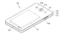
도 1a는 본 발명과 관련된 영상표시장치를 설명하기 위한 블록도이다.
도 1b 및 1c는 본 발명과 관련된 영상표시장치의 일 예를 서로 다른 방향에서 바라본 개념도이다.
도 2는 본 발명의 실시예에 따른 영상표시장치의 제어방법을 설명하기 위한 예시 흐름도이다.
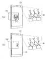
도 3a 및 도 3b는 도 2의 흐름도를 설명하기 위한 개념도들이다.
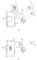
도 4a 및 도 4b는 본 발명의 실시예에 따른 영상표시장치를 기준으로 존재한는 3D 객체의 거리 및 편평도에 따라, 표면에 투영되는 이미지의 형상를 조절하는 방법을 설명하기 위한 개념도들이다.
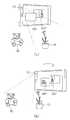
도 5는 본 발명의 실시예에 따른 영상표시장치의 기울기에 따라, 3D 객체에 투영되는 이미지의 명도 및 채도를 조절하는 방법을 설명하기 위한 개념도이다.
도 6은 본 발명의 실시예에 따라, 표면에 이미지가 투영된 3D 객체를 광원으로 다른 3D 객체에 이미지를 재투영시키는 방법을 설명하기 위한 개념도이다.
도 7a 내지 도 7d는 본 발명의 실시예에 따라, 표면에 이미지가 투영된 3D 객체에 대한 사용자 입력에 근거하여, 3D 객체에 투영된 이미지를 변경하는 방법을 설명하기 위한 개념도들이다.
도 8a 내지 도 8c는 본 발명의 실시예에 따라, 카메라의 동작 상태에 따라 3D 객체에 투영된 이미지를 변경하는 방법을 설명하기 위한 개념도들이다.
도 9는 본 발명의 실시예에 따라, 3D 객체에 중첩 투영된 이미지를 디스플레이하는 방법을 설명하기 위한 개념도이다.1A is a block diagram for explaining a video display device related to the present invention.
1B and 1C are conceptual diagrams showing an example of a video display device related to the present invention in different directions.
2 is a flowchart illustrating an example of a method of controlling an image display apparatus according to an exemplary embodiment of the present invention.
FIGS. 3A and 3B are conceptual diagrams for explaining the flow chart of FIG.
4A and 4B are conceptual diagrams for explaining a method of adjusting a shape of an image projected on a surface according to a distance and a flatness of a 3D object existing on the basis of an image display device according to an embodiment of the present invention.
5 is a conceptual diagram for explaining a method of adjusting brightness and chroma of an image projected on a 3D object according to the slope of the image display device according to the embodiment of the present invention.
6 is a conceptual diagram for explaining a method of re-projecting an image on a surface to another 3D object using a light source as a 3D object according to an embodiment of the present invention.
Figs. 7A to 7D are conceptual diagrams for explaining a method of changing a projected image on a 3D object, based on a user input on a 3D object onto which an image is projected, according to an embodiment of the present invention.
8A to 8C are conceptual diagrams illustrating a method of changing an image projected on a 3D object according to an operation state of a camera according to an embodiment of the present invention.
9 is a conceptual diagram for explaining a method of displaying an overlaid projected image on a 3D object according to an embodiment of the present invention.
이하, 첨부된 도면을 참조하여 본 명세서에 개시된 실시 예를 상세히 설명하되, 동일하거나 유사한 구성요소에는 동일/유사한 도면 부호를 부여하고 이에 대한 중복되는 설명은 생략하기로 한다. 이하의 설명에서 사용되는 구성요소에 대한 접미사 "모듈" 및 "부"는 명세서 작성의 용이함만이 고려되어 부여되거나 혼용되는 것으로서, 그 자체로 서로 구별되는 의미 또는 역할을 갖는 것은 아니다. 또한, 본 명세서에 개시된 실시 예를 설명함에 있어서 관련된 공지 기술에 대한 구체적인 설명이 본 명세서에 개시된 실시 예의 요지를 흐릴 수 있다고 판단되는 경우 그 상세한 설명을 생략한다. 또한, 첨부된 도면은 본 명세서에 개시된 실시 예를 쉽게 이해할 수 있도록 하기 위한 것일 뿐, 첨부된 도면에 의해 본 명세서에 개시된 기술적 사상이 제한되지 않으며, 본 발명의 사상 및 기술 범위에 포함되는 모든 변경, 균등물 내지 대체물을 포함하는 것으로 이해되어야 한다.DETAILED DESCRIPTION OF THE PREFERRED EMBODIMENTS Reference will now be made in detail to embodiments of the present invention, examples of which are illustrated in the accompanying drawings, wherein like reference numerals refer to the like elements throughout. The suffix "module" and " part "for the components used in the following description are given or mixed in consideration of ease of specification, and do not have their own meaning or role. In the following description of the embodiments of the present invention, a detailed description of related arts will be omitted when it is determined that the gist of the embodiments disclosed herein may be blurred. It is to be understood that both the foregoing general description and the following detailed description are exemplary and explanatory and are intended to provide further explanation of the invention as claimed. , ≪ / RTI > equivalents, and alternatives.
제1, 제2 등과 같이 서수를 포함하는 용어는 다양한 구성요소들을 설명하는데 사용될 수 있지만, 상기 구성요소들은 상기 용어들에 의해 한정되지는 않는다. 상기 용어들은 하나의 구성요소를 다른 구성요소로부터 구별하는 목적으로만 사용된다.Terms including ordinals, such as first, second, etc., may be used to describe various elements, but the elements are not limited to these terms. The terms are used only for the purpose of distinguishing one component from another.
어떤 구성요소가 다른 구성요소에 "연결되어" 있다거나 "접속되어" 있다고 언급된 때에는, 그 다른 구성요소에 직접적으로 연결되어 있거나 또는 접속되어 있을 수도 있지만, 중간에 다른 구성요소가 존재할 수도 있다고 이해되어야 할 것이다. 반면에, 어떤 구성요소가 다른 구성요소에 "직접 연결되어" 있다거나 "직접 접속되어" 있다고 언급된 때에는, 중간에 다른 구성요소가 존재하지 않는 것으로 이해되어야 할 것이다.It is to be understood that when an element is referred to as being "connected" or "connected" to another element, it may be directly connected or connected to the other element, . On the other hand, when an element is referred to as being "directly connected" or "directly connected" to another element, it should be understood that there are no other elements in between.
단수의 표현은 문맥상 명백하게 다르게 뜻하지 않는 한, 복수의 표현을 포함한다.The singular expressions include plural expressions unless the context clearly dictates otherwise.
본 출원에서, "포함한다" 또는 "가지다" 등의 용어는 명세서상에 기재된 특징, 숫자, 단계, 동작, 구성요소, 부품 또는 이들을 조합한 것이 존재함을 지정하려는 것이지, 하나 또는 그 이상의 다른 특징들이나 숫자, 단계, 동작, 구성요소, 부품 또는 이들을 조합한 것들의 존재 또는 부가 가능성을 미리 배제하지 않는 것으로 이해되어야 한다.In the present application, the terms "comprises", "having", and the like are used to specify that a feature, a number, a step, an operation, an element, a component, But do not preclude the presence or addition of one or more other features, integers, steps, operations, elements, components, or combinations thereof.
본 명세서에서 설명되는 영상표시장치에는 휴대폰, 스마트 폰(smart phone), 노트북 컴퓨터(laptop computer), 디지털방송용 단말기, PDA(personal digital assistants), PMP(portable multimedia player), 네비게이션, 슬레이트 PC(slate PC), 태블릿 PC(tablet PC), 울트라북(ultrabook), 웨어러블 디바이스(wearable device, 예를 들어, 워치형 단말기 (smartwatch), 글래스형 단말기 (smart glass), HMD(head mounted display)) 등이 포함될 수 있다.The video display device described in this specification includes a mobile phone, a smart phone, a laptop computer, a digital broadcasting terminal, a personal digital assistant (PDA), a portable multimedia player (PMP), a navigation device, a slate PC ), Tablet PCs, ultrabooks, wearable devices (e.g., smartwatches, smart glass, HMDs (head mounted displays), etc.) .
그러나, 본 명세서에 기재된 실시 예에 따른 구성은 이동가능한 영상표시장치에만 적용 가능한 경우를 제외하면, 디지털 TV, 데스크탑 컴퓨터, 디지털 사이니지 등과 같은 고정된 영상표시장치에도 적용될 수도 있음을 본 기술분야의 당업자라면 쉽게 알 수 있을 것이다.However, it should be understood that the configuration according to the embodiments described herein may be applied to a fixed image display device such as a digital TV, a desktop computer, a digital signage, and the like, It will be readily apparent to those skilled in the art.
도 1a 내지 도 1c를 참조하면, 도 1a는 본 발명과 관련된 영상표시장치를 설명하기 위한 블록도이고, 도 1b 및 1c는 본 발명과 관련된 영상표시장치의 일 예를 서로 다른 방향에서 바라본 개념도이다.1A through 1C are block diagrams for explaining an image display apparatus according to the present invention, and FIGS. 1B and 1C are conceptual diagrams showing an example of an image display apparatus related to the present invention in different directions .
상기 영상표시장치(100)는 무선 통신부(110), 입력부(120), 감지부(140), 출력부(150), 인터페이스부(160), 메모리(170), 제어부(180) 및 전원 공급부(190) 등을 포함할 수 있다. 도 1a에 도시된 구성요소들은 영상표시장치를 구현하는데 있어서 필수적인 것은 아니어서, 본 명세서상에서 설명되는 영상표시장치는 위에서 열거된 구성요소들 보다 많거나, 또는 적은 구성요소들을 가질 수 있다.The
보다 구체적으로, 상기 구성요소들 중 무선 통신부(110)는, 영상표시장치(100)와 무선 통신 시스템 사이, 영상표시장치(100)와 다른 영상표시장치(100) 사이, 또는 영상표시장치(100)와 외부서버 사이의 무선 통신을 가능하게 하는 하나 이상의 모듈을 포함할 수 있다. 또한, 상기 무선 통신부(110)는, 영상표시장치(100)를 하나 이상의 네트워크에 연결하는 하나 이상의 모듈을 포함할 수 있다.The
이러한 무선 통신부(110)는, 방송 수신 모듈(111), 이동통신 모듈(112), 무선 인터넷 모듈(113), 근거리 통신 모듈(114), 위치정보 모듈(115) 중 적어도 하나를 포함할 수 있다.The
입력부(120)는, 영상 신호 입력을 위한 카메라(121) 또는 영상 입력부, 오디오 신호 입력을 위한 마이크로폰(microphone, 122), 또는 오디오 입력부, 사용자로부터 정보를 입력받기 위한 사용자 입력부(123, 예를 들어, 터치키(touch key), 푸시키(mechanical key) 등)를 포함할 수 있다. 입력부(120)에서 수집한 음성 데이터나 이미지 데이터는 분석되어 사용자의 제어명령으로 처리될 수 있다.The
센싱부(140)는 영상표시장치 내 정보, 영상표시장치를 둘러싼 주변 환경 정보 및 사용자 정보 중 적어도 하나를 센싱하기 위한 하나 이상의 센서를 포함할 수 있다. 예를 들어, 센싱부(140)는 근접센서(141, proximity sensor), 조도 센서(142, illumination sensor), 터치 센서(touch sensor), 가속도 센서(acceleration sensor), 자기 센서(magnetic sensor), 중력 센서(G-sensor), 자이로스코프 센서(gyroscope sensor), 모션 센서(motion sensor), RGB 센서, 적외선 센서(IR 센서: infrared sensor), 지문인식 센서(finger scan sensor), 초음파 센서(ultrasonic sensor), 광 센서(optical sensor, 예를 들어, 카메라(121 참조)), 마이크로폰(microphone, 122 참조), 배터리 게이지(battery gauge), 환경 센서(예를 들어, 기압계, 습도계, 온도계, 방사능 감지 센서, 열 감지 센서, 가스 감지 센서 등), 화학 센서(예를 들어, 전자 코, 헬스케어 센서, 생체 인식 센서 등) 중 적어도 하나를 포함할 수 있다. 한편, 본 명세서에 개시된 영상표시장치는, 이러한 센서들 중 적어도 둘 이상의 센서에서 센싱되는 정보들을 조합하여 활용할 수 있다.The
출력부(150)는 시각, 청각 또는 촉각 등과 관련된 출력을 발생시키기 위한 것으로, 디스플레이부(151), 입체 디스플레이부(152), 음향 출력부(153), 햅팁 모듈(154), 광 출력부(155) 중 적어도 하나를 포함할 수 있다.The
디스플레이부(151)는 터치 센서와 상호 레이어 구조를 이루거나 일체형으로 형성됨으로써, 터치 스크린을 구현할 수 있다. 이러한 터치 스크린은, 영상표시장치(100)와 사용자 사이의 입력 인터페이스를 제공하는 사용자 입력부(123)로써 기능함과 동시에, 영상표시장치(100)와 사용자 사이의 출력 인터페이스를 제공할 수 있다.The
인터페이스부(160)는 영상표시장치(100)에 연결되는 다양한 종류의 외부 기기와의 통로 역할을 수행한다. 이러한 인터페이스부(160)는, 유/무선 헤드셋 포트(port), 외부 충전기 포트(port), 유/무선 데이터 포트(port), 메모리 카드(memory card) 포트, 식별 모듈이 구비된 장치를 연결하는 포트(port), 오디오 I/O(Input/Output) 포트(port), 비디오 I/O(Input/Output) 포트(port), 이어폰 포트(port) 중 적어도 하나를 포함할 수 있다. 영상표시장치(100)에서는, 상기 인터페이스부(160)에 외부 기기가 연결되는 것에 대응하여, 연결된 외부 기기와 관련된 적절할 제어를 수행할 수 있다.The
또한, 메모리(170)는 영상표시장치(100)의 다양한 기능을 지원하는 데이터를 저장한다. 메모리(170)는 영상표시장치(100)에서 구동되는 다수의 응용 프로그램(application program 또는 애플리케이션(application)), 영상표시장치(100)의 동작을 위한 데이터들, 명령어들을 저장할 수 있다. 이러한 응용 프로그램 중 적어도 일부는, 무선 통신을 통해 외부 서버로부터 다운로드 될 수 있다. 또한 이러한 응용 프로그램 중 적어도 일부는, 영상표시장치(100)의 기본적인 기능(예를 들어, 전화 착신, 발신 기능, 메시지 수신, 발신 기능)을 위하여 출고 당시부터 영상표시장치(100)상에 존재할 수 있다. 한편, 응용 프로그램은, 메모리(170)에 저장되고, 영상표시장치(100) 상에 설치되어, 제어부(180)에 의하여 상기 영상표시장치의 동작(또는 기능)을 수행하도록 구동될 수 있다.In addition, the
제어부(180)는 상기 응용 프로그램과 관련된 동작 외에도, 통상적으로 영상표시장치(100)의 전반적인 동작을 제어한다. 제어부(180)는 위에서 살펴본 구성요소들을 통해 입력 또는 출력되는 신호, 데이터, 정보 등을 처리하거나 메모리(170)에 저장된 응용 프로그램을 구동함으로써, 사용자에게 적절한 정보 또는 기능을 제공 또는 처리할 수 있다.In addition to the operations related to the application program, the
또한, 제어부(180)는 메모리(170)에 저장된 응용 프로그램을 구동하기 위하여, 도 1a와 함께 살펴본 구성요소들 중 적어도 일부를 제어할 수 있다. 나아가, 제어부(180)는 상기 응용 프로그램의 구동을 위하여, 영상표시장치(100)에 포함된 구성요소들 중 적어도 둘 이상을 서로 조합하여 동작시킬 수 있다.In addition, the
전원공급부(190)는 제어부(180)의 제어 하에서, 외부의 전원, 내부의 전원을 인가 받아 영상표시장치(100)에 포함된 각 구성요소들에 전원을 공급한다. 이러한 전원공급부(190)는 배터리를 포함하며, 상기 배터리는 내장형 배터리 또는 교체가능한 형태의 배터리가 될 수 있다.The
상기 각 구성요소들 중 적어도 일부는, 이하에서 설명되는 다양한 실시 예들에 따른 영상표시장치의 동작, 제어, 또는 제어방법을 구현하기 위하여 서로 협력하여 동작할 수 있다. 또한, 상기 영상표시장치의 동작, 제어, 또는 제어방법은 상기 메모리(170)에 저장된 적어도 하나의 응용 프로그램의 구동에 의하여 영상표시장치 상에서 구현될 수 있다.At least some of the components may operate in cooperation with one another to implement an operation, control, or control method of an image display device according to various embodiments described below. In addition, the operation, control, or control method of the image display apparatus may be implemented on an image display apparatus by driving at least one application program stored in the
이하에서는, 위에서 살펴본 영상표시장치(100)를 통하여 구현되는 다양한 실시 예들을 살펴보기에 앞서, 위에서 열거된 구성요소들에 대하여, 도 1a를 참조하여 보다 구체적으로 살펴본다.Hereinafter, the components listed above will be described in more detail with reference to FIG. 1A, before explaining various embodiments implemented through the
먼저, 무선 통신부(110)에 대하여 살펴보면, 무선 통신부(110)의 방송 수신 모듈(111)은 방송 채널을 통하여 외부의 방송 관리 서버로부터 방송 신호 및/또는 방송 관련된 정보를 수신한다. 상기 방송 채널은 위성 채널, 지상파 채널을 포함할 수 있다. 적어도 두 개의 방송 채널들에 대한 동시 방송 수신 또는 방송 채널 스위칭을 위해 둘 이상의 상기 방송 수신 모듈이 상기 이동단말기(100)에 제공될 수 있다.First, referring to the
상기 방송 관리 서버는, 방송 신호 및/또는 방송 관련 정보를 생성하여 송신하는 서버 또는 기 생성된 방송 신호 및/또는 방송 관련 정보를 제공받아 단말기에 송신하는 서버를 의미할 수 있다. 상기 방송 신호는, TV 방송 신호, 라디오 방송 신호, 데이터 방송 신호를 포함할 뿐만 아니라, TV 방송 신호 또는 라디오 방송 신호에 데이터 방송 신호가 결합한 형태의 방송 신호도 포함할 수 있다.The broadcast management server may refer to a server for generating and transmitting broadcast signals and / or broadcast related information, or a server for receiving broadcast signals and / or broadcast related information generated by the broadcast management server and transmitting the generated broadcast signals and / or broadcast related information. The broadcast signal may include a TV broadcast signal, a radio broadcast signal, a data broadcast signal, and a broadcast signal in which a data broadcast signal is combined with a TV broadcast signal or a radio broadcast signal.
상기 방송 신호는 디지털 방송 신호의 송수신을 위한 기술표준들(또는 방송방식, 예를 들어, ISO, IEC, DVB, ATSC 등) 중 적어도 하나에 따라 부호화될 수 있으며, 방송 수신 모듈(111)은 상기 기술표준들에서 정한 기술규격에 적합한 방식을 이용하여 상기 디지털 방송 신호를 수신할 수 있다.The broadcasting signal may be encoded according to at least one of technical standards for transmitting and receiving a digital broadcasting signal (or a broadcasting system, for example, ISO, IEC, DVB, ATSC, etc.) It is possible to receive the digital broadcasting signal using a method conforming to the technical standard defined by the technical standards.
상기 방송 관련 정보는, 방송 채널, 방송 프로그램 또는 방송 서비스 제공자에 관련된 정보를 의미할 수 있다. 상기 방송 관련 정보는, 이동통신망을 통하여도 제공될 수 있다. 이러한 경우에는 상기 이동통신 모듈(112)에 의해 수신될 수 있다.The broadcast-related information may be information related to a broadcast channel, a broadcast program, or a broadcast service provider. The broadcast-related information may also be provided through a mobile communication network. In this case, it may be received by the mobile communication module 112.
상기 방송 관련 정보는 예를 들어, DMB(Digital Multimedia Broadcasting)의 EPG(Electronic Program Guide) 또는 DVB-H(Digital Video Broadcast-Handheld)의 ESG(Electronic Service Guide) 등의 다양한 형태로 존재할 수 있다. 방송 수신 모듈(111)을 통해 수신된 방송 신호 및/또는 방송 관련 정보는 메모리(160)에 저장될 수 있다.The broadcast-related information may exist in various forms, for example, an Electronic Program Guide (EPG) of Digital Multimedia Broadcasting (DMB) or an Electronic Service Guide (ESG) of Digital Video Broadcast-Handheld (DVB-H). The broadcast signal and / or broadcast related information received through the
이동통신 모듈(112)은, 이동통신을 위한 기술표준들 또는 통신방식(예를 들어, GSM(Global System for Mobile communication), CDMA(Code Division Multi Access), CDMA2000(Code Division Multi Access 2000), EV-DO(Enhanced Voice-Data Optimized or Enhanced Voice-Data Only), WCDMA(Wideband CDMA), HSDPA(High Speed Downlink Packet Access), HSUPA(High Speed Uplink Packet Access), LTE(Long Term Evolution), LTE-A(Long Term Evolution-Advanced) 등)에 따라 구축된 이동 통신망 상에서 기지국, 외부의 단말, 서버 중 적어도 하나와 무선 신호를 송수신한다.The mobile communication module 112 may be a mobile communication module or a mobile communication module such as a mobile communication module or a mobile communication module that uses technology standards or a communication method (e.g., Global System for Mobile communication (GSM), Code Division Multi Access (CDMA), Code Division Multi Access 2000 (Enhanced Voice-Data Optimized or Enhanced Voice-Data Only), Wideband CDMA (WCDMA), High Speed Downlink Packet Access (HSDPA), High Speed Uplink Packet Access (HSUPA), Long Term Evolution And an external terminal, or a server on a mobile communication network established according to a long term evolution (AR), a long term evolution (AR), or the like.
상기 무선 신호는, 음성 호 신호, 화상 통화 호 신호 또는 문자/멀티미디어 메시지 송수신에 따른 다양한 형태의 데이터를 포함할 수 있다.The wireless signal may include various types of data depending on a voice call signal, a video call signal or a text / multimedia message transmission / reception.
무선 인터넷 모듈(113)은 무선 인터넷 접속을 위한 모듈을 말하는 것으로, 영상표시장치(100)에 내장되거나 외장될 수 있다. 무선 인터넷 모듈(113)은 무선 인터넷 기술들에 따른 통신망에서 무선 신호를 송수신하도록 이루어진다.The
무선 인터넷 기술로는, 예를 들어 WLAN(Wireless LAN), Wi-Fi(Wireless-Fidelity), Wi-Fi(Wireless Fidelity) Direct, DLNA(Digital Living Network Alliance), WiBro(Wireless Broadband), WiMAX(World Interoperability for Microwave Access), HSDPA(High Speed Downlink Packet Access), HSUPA(High Speed Uplink Packet Access), LTE(Long Term Evolution), LTE-A(Long Term Evolution-Advanced) 등이 있으며, 상기 무선 인터넷 모듈(113)은 상기에서 나열되지 않은 인터넷 기술까지 포함한 범위에서 적어도 하나의 무선 인터넷 기술에 따라 데이터를 송수신하게 된다.Wireless Internet technologies include, for example, wireless LAN (WLAN), wireless fidelity (Wi-Fi), wireless fidelity (Wi-Fi) Direct, DLNA (Digital Living Network Alliance), WiBro Interoperability for Microwave Access, High Speed Downlink Packet Access (HSDPA), High Speed Uplink Packet Access (HSUPA), Long Term Evolution (LTE) and Long Term Evolution-Advanced (LTE-A) 113 transmit and receive data according to at least one wireless Internet technology, including Internet technologies not listed above.
WiBro, HSDPA, HSUPA, GSM, CDMA, WCDMA, LTE, LTE-A 등에 의한 무선인터넷 접속은 이동통신망을 통해 이루어진다는 관점에서 본다면, 상기 이동통신망을 통해 무선인터넷 접속을 수행하는 상기 무선 인터넷 모듈(113)은 상기 이동통신 모듈(112)의 일종으로 이해될 수도 있다.The
근거리 통신 모듈(114)은 근거리 통신(Short range communication)을 위한 것으로서, 블루투스(Bluetooth™), RFID(Radio Frequency Identification), 적외선 통신(Infrared Data Association; IrDA), UWB(Ultra Wideband), ZigBee, NFC(Near Field Communication), Wi-Fi(Wireless-Fidelity), Wi-Fi Direct, Wireless USB(Wireless Universal Serial Bus) 기술 중 적어도 하나를 이용하여, 근거리 통신을 지원할 수 있다. 이러한, 근거리 통신 모듈(114)은, 근거리 무선 통신망(Wireless Area Networks)을 통해 영상표시장치(100)와 무선 통신 시스템 사이, 영상표시장치(100)와 다른 영상표시장치(100) 사이, 또는 영상표시장치(100)와 다른 영상표시장치(100, 또는 외부서버)가 위치한 네트워크 사이의 무선 통신을 지원할 수 있다. 상기 근거리 무선 통신망은 근거리 무선 개인 통신망(Wireless Personal Area Networks)일 수 있다.The short-range communication module 114 is for short-range communication, and includes Bluetooth ™, Radio Frequency Identification (RFID), Infrared Data Association (IrDA), Ultra Wideband (UWB) (Near Field Communication), Wi-Fi (Wireless-Fidelity), Wi-Fi Direct, and Wireless USB (Wireless Universal Serial Bus) technology. The local area communication module 114 may be connected to the
여기에서, 다른 영상표시장치(100)는 본 발명에 따른 영상표시장치(100)와 데이터를 상호 교환하는 것이 가능한(또는 연동 가능한) 웨어러블 디바이스(wearable device, 예를 들어, 스마트워치(smartwatch), 스마트 글래스(smart glass), HMD(head mounted display))가 될 수 있다. 근거리 통신 모듈(114)은, 영상표시장치(100) 주변에, 상기 영상표시장치(100)와 통신 가능한 웨어러블 디바이스를 감지(또는 인식)할 수 있다. 나아가, 제어부(180)는 상기 감지된 웨어러블 디바이스가 본 발명에 따른 영상표시장치(100)와 통신하도록 인증된 디바이스인 경우, 영상표시장치(100)에서 처리되는 데이터의 적어도 일부를, 상기 근거리 통신 모듈(114)을 통해 웨어러블 디바이스로 전송할 수 있다. 따라서, 웨어러블 디바이스의 사용자는, 영상표시장치(100)에서 처리되는 데이터를, 웨어러블 디바이스를 통해 이용할 수 있다. 예를 들어, 이에 따르면 사용자는, 영상표시장치(100)에 전화가 수신된 경우, 웨어러블 디바이스를 통해 전화 통화를 수행하거나, 영상표시장치(100)에 메시지가 수신된 경우, 웨어러블 디바이스를 통해 상기 수신된 메시지를 확인하는 것이 가능하다.Here, the other
위치정보 모듈(115)은 영상표시장치의 위치(또는 현재 위치)를 획득하기 위한 모듈로서, 그의 대표적인 예로는 GPS(Global Positioning System) 모듈 또는 WiFi(Wireless Fidelity) 모듈이 있다. 예를 들어, 영상표시장치는 GPS모듈을 활용하면, GPS 위성에서 보내는 신호를 이용하여 영상표시장치의 위치를 획득할 수 있다. 다른 예로서, 영상표시장치는 Wi-Fi모듈을 활용하면, Wi-Fi모듈과 무선신호를 송신 또는 수신하는 무선 AP(Wireless Access Point)의 정보에 기반하여, 영상표시장치의 위치를 획득할 수 있다. 필요에 따라서, 위치정보모듈(115)은 치환 또는 부가적으로 영상표시장치의 위치에 관한 데이터를 얻기 위해 무선 통신부(110)의 다른 모듈 중 어느 기능을 수행할 수 있다. 위치정보모듈(115)은 영상표시장치의 위치(또는 현재 위치)를 획득하기 위해 이용되는 모듈로, 영상표시장치의 위치를 직접적으로 계산하거나 획득하는 모듈로 한정되지는 않는다.The position information module 115 is a module for obtaining the position (or current position) of the image display device, and a representative example thereof is a Global Positioning System (GPS) module or a Wireless Fidelity (WiFi) module. For example, if a video display device utilizes a GPS module, the position of the video display device can be acquired using a signal transmitted from a GPS satellite. As another example, the video display device can utilize the Wi-Fi module to acquire the position of the video display device based on information of a wireless access point (AP) that transmits or receives a wireless signal with the Wi-Fi module have. Optionally, the location information module 115 may substitute or additionally perform any of the other modules of the
다음으로, 입력부(120)는 영상 정보(또는 신호), 오디오 정보(또는 신호), 데이터, 또는 사용자로부터 입력되는 정보의 입력을 위한 것으로서, 영상 정보의 입력을 위하여, 영상표시장치(100) 는 하나 또는 복수의 카메라(121)를 구비할 수 있다. 카메라(121)는 화상 통화모드 또는 촬영 모드에서 이미지 센서에 의해 얻어지는 정지영상 또는 동영상 등의 화상 프레임을 처리한다. 처리된 화상 프레임은 디스플레이부(151)에 표시되거나 메모리(170)에 저장될 수 있다. 한편, 영상표시장치(100)에 구비되는 복수의 카메라(121)는 매트릭스 구조를 이루도록 배치될 수 있으며, 이와 같이 매트릭스 구조를 이루는 카메라(121)를 통하여, 영상표시장치(100)에는 다양한 각도 또는 초점을 갖는 복수의 영상정보가 입력될 수 있다. 또한, 복수의 카메라(121)는 입체영상을 구현하기 위한 좌 영상 및 우 영상을 획득하도록, 스트레오 구조로 배치될 수 있다.Next, the
마이크로폰(122)은 외부의 음향 신호를 전기적인 음성 데이터로 처리한다. 처리된 음성 데이터는 영상표시장치(100)에서 수행 중인 기능(또는 실행 중인 응용 프로그램)에 따라 다양하게 활용될 수 있다. 한편, 마이크로폰(122)에는 외부의 음향 신호를 입력 받는 과정에서 발생되는 잡음(noise)을 제거하기 위한 다양한 잡음 제거 알고리즘이 구현될 수 있다.The
사용자 입력부(123)는 사용자로부터 정보를 입력받기 위한 것으로서, 사용자 입력부(123)를 통해 정보가 입력되면, 제어부(180)는 입력된 정보에 대응되도록 영상표시장치(100)의 동작을 제어할 수 있다. 이러한, 사용자 입력부(123)는 기계식 (mechanical) 입력수단(또는, 메커니컬 키, 예를 들어, 영상표시장치(100)의 전?후면 또는 측면에 위치하는 버튼, 돔 스위치 (dome switch), 조그 휠, 조그 스위치 등) 및 터치식 입력수단을 포함할 수 있다. 일 예로서, 터치식 입력수단은, 소프트웨어적인 처리를 통해 터치스크린에 표시되는 가상 키(virtual key), 소프트 키(soft key) 또는 비주얼 키(visual key)로 이루어지거나, 상기 터치스크린 이외의 부분에 배치되는 터치 키(touch key)로 이루어질 수 있다. 한편, 상기 가상키 또는 비주얼 키는, 다양한 형태를 가지면서 터치스크린 상에 표시되는 것이 가능하며, 예를 들어, 그래픽(graphic), 텍스트(text), 아이콘(icon), 비디오(video) 또는 이들의 조합으로 이루어질 수 있다.The
한편, 센싱부(140)는 영상표시장치 내 정보, 영상표시장치를 둘러싼 주변 환경 정보 및 사용자 정보 중 적어도 하나를 센싱하고, 이에 대응하는 센싱 신호를 발생시킨다. 제어부(180)는 이러한 센싱 신호에 기초하여, 영상표시장치(100)의 구동 또는 동작을 제어하거나, 영상표시장치(100)에 설치된 응용 프로그램과 관련된 데이터 처리, 기능 또는 동작을 수행 할 수 있다. 센싱부(140)에 포함될 수 있는 다양한 센서 중 대표적인 센서들의 대하여, 보다 구체적으로 살펴본다.Meanwhile, the
먼저, 근접 센서(141)는 소정의 검출면에 접근하는 물체, 혹은 근방에 존재하는 물체의 유무를 전자계의 힘 또는 적외선 등을 이용하여 기계적 접촉이 없이 검출하는 센서를 말한다. 이러한 근접 센서(141)는 위에서 살펴본 터치 스크린에 의해 감싸지는 영상표시장치의 내부 영역 또는 상기 터치 스크린의 근처에 근접 센서(141)가 배치될 수 있다.First, the
근접 센서(141)의 예로는 투과형 광전 센서, 직접 반사형 광전 센서, 미러 반사형 광전 센서, 고주파 발진형 근접 센서, 정전 용량형 근접 센서, 자기형 근접 센서, 적외선 근접 센서 등이 있다. 터치 스크린이 정전식인 경우에, 근접 센서(141)는 전도성을 갖는 물체의 근접에 따른 전계의 변화로 상기 물체의 근접을 검출하도록 구성될 수 있다. 이 경우 터치 스크린(또는 터치 센서) 자체가 근접 센서로 분류될 수 있다.Examples of the
한편, 설명의 편의를 위해, 터치 스크린 상에 물체가 접촉되지 않으면서 근접되어 상기 물체가 상기 터치 스크린 상에 위치함이 인식되도록 하는 행위를 "근접 터치(proximity touch)"라고 명명하고, 상기 터치 스크린 상에 물체가 실제로 접촉되는 행위를 "접촉 터치(contact touch)"라고 명명한다. 상기 터치 스크린 상에서 물체가 근접 터치 되는 위치라 함은, 상기 물체가 근접 터치될 때 상기 물체가 상기 터치 스크린에 대해 수직으로 대응되는 위치를 의미한다. 상기 근접 센서(141)는, 근접 터치와, 근접 터치 패턴(예를 들어, 근접 터치 거리, 근접 터치 방향, 근접 터치 속도, 근접 터치 시간, 근접 터치 위치, 근접 터치 이동 상태 등)을 감지할 수 있다. 한편, 제어부(180)는 위와 같이, 근접 센서(141)를 통해 감지된 근접 터치 동작 및 근접 터치 패턴에 상응하는 데이터(또는 정보)를 처리하며, 나아가, 처리된 데이터에 대응하는 시각적인 정보를 터치 스크린상에 출력시킬 수 있다. 나아가, 제어부(180)는, 터치 스크린 상의 동일한 지점에 대한 터치가, 근접 터치인지 또는 접촉 터치인지에 따라, 서로 다른 동작 또는 데이터(또는 정보)가 처리되도록 영상표시장치(100)를 제어할 수 있다.On the other hand, for convenience of explanation, the act of recognizing that the object is located on the touch screen in proximity with no object touching the touch screen is referred to as "proximity touch & The act of actually touching an object on the screen is called a "contact touch. &Quot; The position at which the object is closely touched on the touch screen means a position where the object corresponds to the touch screen vertically when the object is touched. The
터치 센서는 저항막 방식, 정전용량 방식, 적외선 방식, 초음파 방식, 자기장 방식 등 여러가지 터치방식 중 적어도 하나를 이용하여 터치 스크린(또는 디스플레이부(151))에 가해지는 터치(또는 터치입력)을 감지한다.The touch sensor senses a touch (or touch input) applied to the touch screen (or the display unit 151) by using at least one of various touch methods such as a resistance film type, a capacitive type, an infrared type, an ultrasonic type, do.
일 예로서, 터치 센서는, 터치 스크린의 특정 부위에 가해진 압력 또는 특정 부위에 발생하는 정전 용량 등의 변화를 전기적인 입력신호로 변환하도록 구성될 수 있다. 터치 센서는, 터치 스크린 상에 터치를 가하는 터치 대상체가 터치 센서 상에 터치 되는 위치, 면적, 터치 시의 압력, 터치 시의 정전 용량 등을 검출할 수 있도록 구성될 수 있다. 여기에서, 터치 대상체는 상기 터치 센서에 터치를 인가하는 물체로서, 예를 들어, 손가락, 터치펜 또는 스타일러스 펜(Stylus pen), 포인터 등이 될 수 있다.For example, the touch sensor may be configured to convert a change in a pressure applied to a specific portion of the touch screen or a capacitance generated in a specific portion to an electrical input signal. The touch sensor may be configured to detect a position, an area, a pressure at the time of touch, a capacitance at the time of touch, and the like where a touch object touching the touch screen is touched on the touch sensor. Here, the touch object may be a finger, a touch pen, a stylus pen, a pointer, or the like as an object to which a touch is applied to the touch sensor.
이와 같이, 터치 센서에 대한 터치 입력이 있는 경우, 그에 대응하는 신호(들)는 터치 제어기로 보내진다. 터치 제어기는 그 신호(들)를 처리한 다음 대응하는 데이터를 제어부(180)로 전송한다. 이로써, 제어부(180)는 디스플레이부(151)의 어느 영역이 터치 되었는지 여부 등을 알 수 있게 된다. 여기에서, 터치 제어기는, 제어부(180)와 별도의 구성요소일 수 있고, 제어부(180) 자체일 수 있다.Thus, when there is a touch input to the touch sensor, the corresponding signal (s) is sent to the touch controller. The touch controller processes the signal (s) and transmits the corresponding data to the
한편, 제어부(180)는, 터치 스크린(또는 터치 스크린 이외에 구비된 터치키)을 터치하는, 터치 대상체의 종류에 따라 서로 다른 제어를 수행하거나, 동일한 제어를 수행할 수 있다. 터치 대상체의 종류에 따라 서로 다른 제어를 수행할지 또는 동일한 제어를 수행할 지는, 현재 영상표시장치(100)의 동작상태 또는 실행 중인 응용 프로그램에 따라 결정될 수 있다.On the other hand, the
한편, 위에서 살펴본 터치 센서 및 근접 센서는 독립적으로 또는 조합되어, 터치 스크린에 대한 숏(또는 탭) 터치(short touch), 롱 터치(long touch), 멀티 터치(multi touch), 드래그 터치(drag touch), 플리크 터치(flick touch), 핀치-인 터치(pinch-in touch), 핀치-아웃 터치(pinch-out 터치), 스와이프(swype) 터치, 호버링(hovering) 터치 등과 같은, 다양한 방식의 터치를 센싱할 수 있다.On the other hand, the touch sensors and the proximity sensors discussed above can be used independently or in combination to provide a short touch (touch), a long touch, a multi touch, a drag touch ), Flick touch, pinch-in touch, pinch-out touch, swipe touch, hovering touch, and the like. Touch can be sensed.
초음파 센서는 초음파를 이용하여, 감지대상의 위치정보를 인식할 수 있다. 한편 제어부(180)는 광 센서와 복수의 초음파 센서로부터 감지되는 정보를 통해, 파동 발생원의 위치를 산출하는 것이 가능하다. 파동 발생원의 위치는, 광이 초음파보다 매우 빠른 성질, 즉, 광이 광 센서에 도달하는 시간이 초음파가 초음파 센서에 도달하는 시간보다 매우 빠름을 이용하여, 산출될 수 있다. 보다 구체적으로 광을 기준 신호로 초음파가 도달하는 시간과의 시간차를 이용하여 파동 발생원의 위치가 산출될 수 있다.The ultrasonic sensor can recognize the position information of the object to be sensed by using ultrasonic waves. Meanwhile, the
한편, 입력부(120)의 구성으로 살펴본, 카메라(121)는 카메라 센서(예를 들어, CCD, CMOS 등), 포토 센서(또는 이미지 센서) 및 레이저 센서 중 적어도 하나를 포함한다.The
카메라(121)와 레이저 센서는 서로 조합되어, 3차원 입체영상에 대한 감지대상의 터치를 감지할 수 있다. 포토 센서는 디스플레이 소자에 적층될 수 있는데, 이러한 포토 센서는 터치 스크린에 근접한 감지대상의 움직임을 스캐닝하도록 이루어진다. 보다 구체적으로, 포토 센서는 행/열에 Photo Diode와 TR(Transistor)를 실장하여 Photo Diode에 인가되는 빛의 양에 따라 변화되는 전기적 신호를 이용하여 포토 센서 위에 올려지는 내용물을 스캔한다. 즉, 포토 센서는 빛의 변화량에 따른 감지대상의 좌표 계산을 수행하며, 이를 통하여 감지대상의 위치정보가 획득될 수 있다.The
디스플레이부(151)는 영상표시장치(100)에서 처리되는 정보를 표시(출력)한다. 예를 들어, 디스플레이부(151)는 영상표시장치(100)에서 구동되는 응용 프로그램의 실행화면 정보, 또는 이러한 실행화면 정보에 따른 UI(User Interface), GUI(Graphic User Interface) 정보를 표시할 수 있다.The
또한, 상기 디스플레이부(151)는 입체영상을 표시하는 입체 디스플레이부(152)로서 구성될 수 있다.Also, the
상기 입체 디스플레이부(152)에는 스테레오스코픽 방식(안경 방식), 오토 스테레오스코픽 방식(무안경 방식), 프로젝션 방식(홀로그래픽 방식) 등의 3차원 디스플레이 방식이 적용될 수 있다.The
일반적으로 3차원 입체 영상은 좌 영상(좌안용 영상)과 우 영상(우안용 영상)으로 구성된다. 좌 영상과 우 영상이 3차원 입체 영상으로 합쳐지는 방식에 따라, 좌 영상과 우 영상을 한 프레임 내 상하로 배치하는 탑-다운(top-down) 방식, 좌 영상과 우 영상을 한 프레임 내 좌우로 배치하는 L-to-R(left-to-right, side by side) 방식, 좌 영상과 우 영상의 조각들을 타일 형태로 배치하는 체커 보드(checker board) 방식, 좌 영상과 우 영상을 열 단위 또는 행 단위로 번갈아 배치하는 인터레이스드(interlaced) 방식, 그리고 좌 영상과 우 영상을 시간 별로 번갈아 표시하는 시분할(time sequential, frame by frame) 방식 등으로 나뉜다.Generally, 3D stereoscopic images consist of left image (left eye image) and right image (right eye image). A top-down method of arranging a left image and a right image in one frame according to a method in which a left image and a right image are combined into a three-dimensional stereoscopic image, A checker board system in which pieces of a left image and a right image are arranged in a tile form, a left-to-right (right-side) Or an interlaced method in which rows are alternately arranged, and a time sequential (frame-by-frame) method in which right and left images are alternately displayed in time.
또한, 3차원 썸네일 영상은 원본 영상 프레임의 좌 영상 및 우 영상으로부터 각각 좌 영상 썸네일 및 우 영상 썸네일을 생성하고, 이들이 합쳐짐에 따라 하나의 영상으로 생성될 수 있다. 일반적으로 썸네일(thumbnail)은 축소된 화상 또는 축소된 정지영상을 의미한다. 이렇게 생성된 좌 영상 썸네일과 우 영상 썸네일은 좌 영상과 우 영상의 시차에 대응하는 깊이감(depth)만큼 화면상에서 좌우 거리차를 두고 표시됨으로써 입체적인 공간감을 나타낼 수 있다.In addition, the 3D thumbnail image may generate a left image thumbnail and a right image thumbnail from the left image and right image of the original image frame, respectively, and may be generated as one image as they are combined. In general, a thumbnail means a reduced image or a reduced still image. The left image thumbnail and the right image thumbnail generated in this way are displayed on the screen with a difference of the left and right distance by the depth corresponding to the parallax between the left image and the right image, thereby exhibiting a stereoscopic spatial feeling.
3차원 입체영상의 구현에 필요한 좌 영상과 우 영상은 입체 처리부에 의하여 입체 디스플레이부(152)에 표시될 수 있다. 입체 처리부는 3D 영상(기준시점의 영상과 확장시점의 영상)을 입력받아, 이로부터 좌 영상과 우 영상을 설정하거나, 2D 영상을 입력 받아 이를 좌 영상과 우 영상으로 전환하도록 이루어진다.The left and right images necessary for realizing the three-dimensional stereoscopic image can be displayed on the
음향 출력부(153)는 호신호 수신, 통화모드 또는 녹음 모드, 음성인식 모드, 방송수신 모드 등에서 무선 통신부(110)로부터 수신되거나 메모리(170)에 저장된 오디오 데이터를 출력할 수 있다. 음향 출력부(153)는 영상표시장치(100)에서 수행되는 기능(예를 들어, 호신호 수신음, 메시지 수신음 등)과 관련된 음향 신호를 출력하기도 한다. 이러한 음향 출력부(153)에는 리시버(receiver), 스피커(speaker), 버저(buzzer) 등이 포함될 수 있다.The
햅틱 모듈(haptic module)(154)은 사용자가 느낄 수 있는 다양한 촉각 효과를 발생시킨다. 햅틱 모듈(154)이 발생시키는 촉각 효과의 대표적인 예로는 진동이 될 수 있다. 햅틱 모듈(154)에서 발생하는 진동의 세기와 패턴 등은 사용자의 선택 또는 제어부의 설정에 의해 제어될 수 있다. 예를 들어, 상기 햅틱 모듈(154)은 서로 다른 진동을 합성하여 출력하거나 순차적으로 출력할 수도 있다.The
햅틱 모듈(154)은, 진동 외에도, 접촉 피부면에 대해 수직 운동하는 핀 배열, 분사구나 흡입구를 통한 공기의 분사력이나 흡입력, 피부 표면에 대한 스침, 전극(electrode)의 접촉, 정전기력 등의 자극에 의한 효과와, 흡열이나 발열 가능한 소자를 이용한 냉온감 재현에 의한 효과 등 다양한 촉각 효과를 발생시킬 수 있다.In addition to the vibration, the
햅틱 모듈(154)은 직접적인 접촉을 통해 촉각 효과를 전달할 수 있을 뿐만 아니라, 사용자가 손가락이나 팔 등의 근 감각을 통해 촉각 효과를 느낄 수 있도록 구현할 수도 있다. 햅틱 모듈(154)은 영상표시장치(100)의 구성 태양에 따라 2개 이상이 구비될 수 있다.The
광출력부(155)는 영상표시장치(100)의 광원의 빛을 이용하여 이벤트 발생을 알리기 위한 신호를 출력한다. 영상표시장치(100)에서 발생 되는 이벤트의 예로는 메시지 수신, 호 신호 수신, 부재중 전화, 알람, 일정 알림, 이메일 수신, 애플리케이션을 통한 정보 수신 등이 될 수 있다.The
광출력부(155)가 출력하는 신호는 영상표시장치가 전면이나 후면으로 단색이나 복수색의 빛을 발광함에 따라 구현된다. 상기 신호 출력은 영상표시장치가 사용자의 이벤트 확인을 감지함에 의하여 종료될 수 있다.The signal output from the
인터페이스부(160)는 영상표시장치(100)에 연결되는 모든 외부 기기와의 통로 역할을 한다. 인터페이스부(160)는 외부 기기로부터 데이터를 전송받거나, 전원을 공급받아 영상표시장치(100) 내부의 각 구성요소에 전달하거나, 영상표시장치(100) 내부의 데이터가 외부 기기로 전송되도록 한다. 예를 들어, 유/무선 헤드셋 포트(port), 외부 충전기 포트(port), 유/무선 데이터 포트(port), 메모리 카드(memory card) 포트(port), 식별 모듈이 구비된 장치를 연결하는 포트(port), 오디오 I/O(Input/Output) 포트(port), 비디오 I/O(Input/Output) 포트(port), 이어폰 포트(port) 등이 인터페이스부(160)에 포함될 수 있다.The
한편, 식별 모듈은 영상표시장치(100)의 사용 권한을 인증하기 위한 각종 정보를 저장한 칩으로서, 사용자 인증 모듈(user identify module; UIM), 가입자 인증 모듈(subscriber identity module; SIM), 범용 사용자 인증 모듈(universal subscriber identity module; USIM) 등을 포함할 수 있다. 식별 모듈이 구비된 장치(이하 '식별 장치')는, 스마트 카드(smart card) 형식으로 제작될 수 있다. 따라서 식별 장치는 상기 인터페이스부(160)를 통하여 단말기(100)와 연결될 수 있다.The identification module is a chip for storing various information for authenticating the usage right of the
또한, 상기 인터페이스부(160)는 영상표시장치(100)가 외부 크래들(cradle)과 연결될 때 상기 크래들로부터의 전원이 상기 영상표시장치(100)에 공급되는 통로가 되거나, 사용자에 의해 상기 크래들에서 입력되는 각종 명령 신호가 상기 영상표시장치(100)로 전달되는 통로가 될 수 있다. 상기 크래들로부터 입력되는 각종 명령 신호 또는 상기 전원은 상기 영상표시장치(100)가 상기 크래들에 정확히 장착되었음을 인지하기 위한 신호로 동작될 수 있다.The
메모리(170)는 제어부(180)의 동작을 위한 프로그램을 저장할 수 있고, 입/출력되는 데이터들(예를 들어, 폰북, 메시지, 정지영상, 동영상 등)을 임시 저장할 수도 있다. 상기 메모리(170)는 상기 터치 스크린 상의 터치 입력시 출력되는 다양한 패턴의 진동 및 음향에 관한 데이터를 저장할 수 있다.The
메모리(170)는 플래시 메모리 타입(flash memory type), 하드디스크 타입(hard disk type), SSD 타입(Solid State Disk type), SDD 타입(Silicon Disk Drive type), 멀티미디어 카드 마이크로 타입(multimedia card micro type), 카드 타입의 메모리(예를 들어 SD 또는 XD 메모리 등), 램(random access memory; RAM), SRAM(static random access memory), 롬(read-only memory; ROM), EEPROM(electrically erasable programmable read-only memory), PROM(programmable read-only memory), 자기 메모리, 자기 디스크 및 광디스크 중 적어도 하나의 타입의 저장매체를 포함할 수 있다. 영상표시장치(100)는 인터넷(internet)상에서 상기 메모리(170)의 저장 기능을 수행하는 웹 스토리지(web storage)와 관련되어 동작될 수도 있다.The
한편, 앞서 살펴본 것과 같이, 제어부(180)는 응용 프로그램과 관련된 동작과, 통상적으로 영상표시장치(100)의 전반적인 동작을 제어한다. 예를 들어, 제어부(180)는 상기 영상표시장치의 상태가 설정된 조건을 만족하면, 애플리케이션들에 대한 사용자의 제어 명령의 입력을 제한하는 잠금 상태를 실행하거나, 해제할 수 있다.Meanwhile, as described above, the
또한, 제어부(180)는 음성 통화, 데이터 통신, 화상 통화 등과 관련된 제어 및 처리를 수행하거나, 터치 스크린 상에서 행해지는 필기 입력 또는 그림 그리기 입력을 각각 문자 및 이미지로 인식할 수 있는 패턴 인식 처리를 행할 수 있다. 나아가 제어부(180)는 이하에서 설명되는 다양한 실시 예들을 본 발명에 따른 영상표시장치(100) 상에서 구현하기 위하여, 위에서 살펴본 구성요소들을 중 어느 하나 또는 복수를 조합하여 제어할 수 있다.In addition, the
전원 공급부(190)는 제어부(180)의 제어에 의해 외부의 전원, 내부의 전원을 인가 받아 각 구성요소들의 동작에 필요한 전원을 공급한다. 전원공급부(190)는 배터리를 포함하며, 배터리는 충전 가능하도록 이루어지는 내장형 배터리가 될 수 있으며, 충전 등을 위하여 단말기 바디에 착탈 가능하게 결합될 수 있다.The
또한, 전원공급부(190)는 연결포트를 구비할 수 있으며, 연결포트는 배터리의 충전을 위하여 전원을 공급하는 외부 충전기가 전기적으로 연결되는 인터페이스(160)의 일 예로서 구성될 수 있다.In addition, the
다른 예로서, 전원공급부(190)는 상기 연결포트를 이용하지 않고 무선방식으로 배터리를 충전하도록 이루어질 수 있다. 이 경우에, 전원공급부(190)는 외부의 무선 전력 전송장치로부터 자기 유도 현상에 기초한 유도 결합(Inductive Coupling) 방식이나 전자기적 공진 현상에 기초한 공진 결합(Magnetic Resonance Coupling) 방식 중 하나 이상을 이용하여 전력을 전달받을 수 있다.As another example, the
한편, 이하에서 다양한 실시 예는 예를 들어, 소프트웨어, 하드웨어 또는 이들의 조합된 것을 이용하여 컴퓨터 또는 이와 유사한 장치로 읽을 수 있는 기록매체 내에서 구현될 수 있다.In the following, various embodiments may be embodied in a recording medium readable by a computer or similar device using, for example, software, hardware, or a combination thereof.
도 1 b 및 1c를 참조하면, 개시된 영상표시장치(100)는 바 형태의 단말기 바디를 구비하고 있다. 다만, 본 발명은 여기에 한정되지 않고 와치 타입, 클립 타입, 글래스 타입 또는 2 이상의 바디들이 상대 이동 가능하게 결합되는 폴더 타입, 플립 타입, 슬라이드 타입, 스윙 타입, 스위블 타입 등 다양한 구조에 적용될 수 있다. 영상표시장치의 특정 유형에 관련될 것이나, 영상표시장치의 특정유형에 관한 설명은 다른 타입의 영상표시장치에 일반적으로 적용될 수 있다.Referring to FIGS. 1B and 1C, the
여기에서, 단말기 바디는 영상표시장치(100)를 적어도 하나의 집합체로 보아 이를 지칭하는 개념으로 이해될 수 있다.Here, the terminal body can be understood as a concept of referring to the
영상표시장치(100)는 외관을 이루는 케이스(예를 들면, 프레임, 하우징, 커버 등)를 포함한다. 도시된 바와 같이, 영상표시장치(100)는 프론트 케이스(101)와 리어 케이스(102)를 포함할 수 있다. 프론트 케이스(101)와 리어 케이스(102)의 결합에 의해 형성되는 내부공간에는 각종 전자부품들이 배치된다. 프론트 케이스(101)와 리어 케이스(102) 사이에는 적어도 하나의 미들 케이스가 추가로 배치될 수 있다.The
단말기 바디의 전면에는 디스플레이부(151)가 배치되어 정보를 출력할 수 있다. 도시된 바와 같이, 디스플레이부(151)의 윈도우(151a)는 프론트 케이스(101)에 장착되어 프론트 케이스(101)와 함께 단말기 바디의 전면을 형성할 수 있다.A
경우에 따라서, 리어 케이스(102)에도 전자부품이 장착될 수 있다. 리어 케이스(102)에 장착 가능한 전자부품은 착탈 가능한 배터리, 식별 모듈, 메모리 카드 등이 있다. 이 경우, 리어 케이스(102)에는 장착된 전자부품을 덮기 위한 후면커버(103)가 착탈 가능하게 결합될 수 있다. 따라서, 후면 커버(103)가 리어 케이스(102)로부터 분리되면, 리어 케이스(102)에 장착된 전자부품은 외부로 노출된다.In some cases, electronic components may also be mounted on the
도시된 바와 같이, 후면커버(103)가 리어 케이스(102)에 결합되면, 리어 케이스(102)의 측면 일부가 노출될 수 있다. 경우에 따라서, 상기 결합시 리어 케이스(102)는 후면커버(103)에 의해 완전히 가려질 수도 있다. 한편, 후면커버(103)에는 카메라(121b)나 음향 출력부(152b)를 외부로 노출시키기 위한 개구부가 구비될 수 있다.As shown, when the
이러한 케이스들(101, 102, 103)은 합성수지를 사출하여 형성되거나 금속, 예를 들어 스테인레스 스틸(STS), 알루미늄(Al), 티타늄(Ti) 등으로 형성될 수도 있다.These
영상표시장치(100)는, 복수의 케이스가 각종 전자부품들을 수용하는 내부 공간을 마련하는 위의 예와 달리, 하나의 케이스가 상기 내부 공간을 마련하도록 구성될 수도 있다. 이 경우, 합성수지 또는 금속이 측면에서 후면으로 이어지는 유니 바디의 영상표시장치(100)가 구현될 수 있다.The
한편, 영상표시장치(100)는 단말기 바디 내부로 물이 스며들지 않도록 하는 방수부(미도시)를 구비할 수 있다. 예를 들어, 방수부는 윈도우(151a)와 프론트 케이스(101) 사이, 프론트 케이스(101)와 리어 케이스(102) 사이 또는 리어 케이스(102)와 후면 커버(103) 사이에 구비되어, 이들의 결합 시 내부 공간을 밀폐하는 방수부재를 포함할 수 있다.Meanwhile, the
영상표시장치(100)에는 디스플레이부(151), 제1 및 제2 음향 출력부(152a, 152b), 근접 센서(141), 조도 센서(142), 광 출력부(155), 제1 및 제2 카메라(121a, 121b), 제1 및 제2 조작유닛(123a, 123b), 마이크로폰(122), 인터페이스부(160) 등이 구비될 수 있다.The
이하에서는, 도 1b 및 도 1c에 도시된 바와 같이, 단말기 바디의 전면에 디스플레이부(151), 제1 음향 출력부(152a), 근접 센서(141), 조도 센서(142), 광 출력부(155), 제1 카메라(121a) 및 제1 조작유닛(123a)이 배치되고, 단말기 바디의 측면에 제2 조작유닛(123b), 마이크로폰(122) 및 인터페이스부(160)이 배치되며, 단말기 바디의 후면에 제2 음향 출력부(152b) 및 제2 카메라(121b)가 배치된 영상표시장치(100)를 일 예로 들어 설명한다.1B and 1C, a
다만, 이들 구성은 이러한 배치에 한정되는 것은 아니다. 이들 구성은 필요에 따라 제외 또는 대체되거나, 다른 면에 배치될 수 있다. 예를 들어, 단말기 바디의 전면에는 제1 조작유닛(123a)이 구비되지 않을 수 있으며, 제2 음향 출력부(152b)는 단말기 바디의 후면이 아닌 단말기 바디의 측면에 구비될 수 있다.However, these configurations are not limited to this arrangement. These configurations may be excluded or replaced as needed, or placed on different planes. For example, the
디스플레이부(151)는 영상표시장치(100)에서 처리되는 정보를 표시(출력)한다. 예를 들어, 디스플레이부(151)는 영상표시장치(100)에서 구동되는 응용 프로그램의 실행화면 정보, 또는 이러한 실행화면 정보에 따른 UI(User Interface), GUI(Graphic User Interface) 정보를 표시할 수 있다.The
디스플레이부(151)는 액정 디스플레이(liquid crystal display, LCD), 박막 트랜지스터 액정 디스플레이(thin film transistor-liquid crystal display, TFT LCD), 유기 발광 다이오드(organic light-emitting diode, OLED), 플렉서블 디스플레이(flexible display), 3차원 디스플레이(3D display), 전자잉크 디스플레이(e-ink display) 중에서 적어도 하나를 포함할 수 있다.The
또한, 디스플레이부(151)는 영상표시장치(100)의 구현 형태에 따라 2개 이상 존재할 수 있다. 이 경우, 영상표시장치(100)에는 복수의 디스플레이부들이 하나의 면에 이격되거나 일체로 배치될 수 있고, 또한 서로 다른 면에 각각 배치될 수도 있다.In addition, the
디스플레이부(151)는 터치 방식에 의하여 제어 명령을 입력 받을 수 있도록, 디스플레이부(151)에 대한 터치를 감지하는 터치센서를 포함할 수 있다. 이를 이용하여, 디스플레이부(151)에 대하여 터치가 이루어지면, 터치센서는 상기 터치를 감지하고, 제어부(180)는 이에 근거하여 상기 터치에 대응하는 제어명령을 발생시키도록 이루어질 수 있다. 터치 방식에 의하여 입력되는 내용은 문자 또는 숫자이거나, 각종 모드에서의 지시 또는 지정 가능한 메뉴항목 등일 수 있다.The
한편, 터치센서는, 터치패턴을 구비하는 필름 형태로 구성되어 윈도우(151a)와 윈도우(151a)의 배면 상의 디스플레이(미도시) 사이에 배치되거나, 윈도우(151a)의 배면에 직접 패터닝되는 메탈 와이어가 될 수도 있다. 또는, 터치센서는 디스플레이와 일체로 형성될 수 있다. 예를 들어, 터치센서는, 디스플레이의 기판 상에 배치되거나, 디스플레이의 내부에 구비될 수 있다.The touch sensor may be a film having a touch pattern and disposed between the
이처럼, 디스플레이부(151)는 터치센서와 함께 터치 스크린을 형성할 수 있으며, 이 경우에 터치 스크린은 사용자 입력부(123, 도 1a 참조)로 기능할 수 있다. 경우에 따라, 터치 스크린은 제1조작유닛(123a)의 적어도 일부 기능을 대체할 수 있다.In this way, the
제1 음향 출력부(152a)는 통화음을 사용자의 귀에 전달시키는 리시버(receiver)로 구현될 수 있으며, 제2 음향 출력부(152b)는 각종 알람음이나 멀티미디어의 재생음을 출력하는 라우드 스피커(loud speaker)의 형태로 구현될 수 있다.The first
디스플레이부(151)의 윈도우(151a)에는 제1 음향 출력부(152a)로부터 발생되는 사운드의 방출을 위한 음향홀이 형성될 수 있다. 다만, 본 발명은 이에 한정되는 것은 아니고, 상기 사운드는 구조물 간의 조립틈(예를 들어, 윈도우(151a)와 프론트 케이스(101) 간의 틈)을 따라 방출되도록 구성될 수 있다. 이 경우, 외관상 음향 출력을 위하여 독립적으로 형성되는 홀이 보이지 않거나 숨겨져 영상표시장치(100)의 외관이 보다 심플해질 수 있다.The
광 출력부(155)는 이벤트의 발생시 이를 알리기 위한 빛을 출력하도록 이루어진다. 상기 이벤트의 예로는 메시지 수신, 호 신호 수신, 부재중 전화, 알람, 일정 알림, 이메일 수신, 애플리케이션을 통한 정보 수신 등을 들 수 있다. 제어부(180)는 사용자의 이벤트 확인이 감지되면, 빛의 출력이 종료되도록 광 출력부(155)를 제어할 수 있다.The
제1 카메라(121a)는 촬영 모드 또는 화상통화 모드에서 이미지 센서에 의해 얻어지는 정지영상 또는 동영상의 화상 프레임을 처리한다. 처리된 화상 프레임은 디스플레이부(151)에 표시될 수 있으며, 메모리(170)에 저장될 수 있다.The
제1 및 제2 조작유닛(123a, 123b)은 영상표시장치(100)의 동작을 제어하기 위한 명령을 입력 받기 위해 조작되는 사용자 입력부(123)의 일 예로서, 조작부(manipulating portion)로도 통칭될 수 있다. 제1 및 제2 조작유닛(123a, 123b)은 터치, 푸시, 스크롤 등 사용자가 촉각적인 느낌을 받으면서 조작하게 되는 방식(tactile manner)이라면 어떤 방식이든 채용될 수 있다. 또한, 제1 및 제2 조작유닛(123a, 123b)은 근접 터치(proximity touch), 호버링(hovering) 터치 등을 통해서 사용자의 촉각적인 느낌이 없이 조작하게 되는 방식으로도 채용될 수 있다.The first and
본 도면에서는 제1 조작유닛(123a)이 터치키(touch key)인 것으로 예시하나, 본 발명이 이에 한정되는 것은 아니다. 예를 들어, 제1 조작유닛(123a)은 푸시키(mechanical key)가 되거나, 터치키와 푸시키의 조합으로 구성될 수 있다.In this figure, the
제1 및 제2 조작유닛(123a, 123b)에 의하여 입력되는 내용은 다양하게 설정될 수 있다. 예를 들어, 제1 조작유닛(123a)은 메뉴, 홈키, 취소, 검색 등의 명령을 입력 받고, 제2 조작유닛(123b)은 제1 또는 제2 음향 출력부(152a, 152b)에서 출력되는 음향의 크기 조절, 디스플레이부(151)의 터치 인식 모드로의 전환 등의 명령을 입력 받을 수 있다.The contents input by the first and
한편, 단말기 바디의 후면에는 사용자 입력부(123)의 다른 일 예로서, 후면 입력부(미도시)가 구비될 수 있다. 이러한 후면 입력부는 영상표시장치(100)의 동작을 제어하기 위한 명령을 입력 받기 위해 조작되는 것으로서, 입력되는 내용은 다양하게 설정될 수 있다. 예를 들어, 전원의 온/오프, 시작, 종료, 스크롤 등과 같은 명령, 제1 및 제2 음향 출력부(152a, 152b)에서 출력되는 음향의 크기 조절, 디스플레이부(151)의 터치 인식 모드로의 전환 등과 같은 명령을 입력 받을 수 있다. 후면 입력부는 터치입력, 푸시입력 또는 이들의 조합에 의한 입력이 가능한 형태로 구현될 수 있다.On the other hand, a rear input unit (not shown) may be provided on the rear surface of the terminal body as another example of the
후면 입력부는 단말기 바디의 두께방향으로 전면의 디스플레이부(151)와 중첩되게 배치될 수 있다. 일 예로, 사용자가 단말기 바디를 한 손으로 쥐었을 때 검지를 이용하여 용이하게 조작 가능하도록, 후면 입력부는 단말기 바디의 후면 상단부에 배치될 수 있다. 다만, 본 발명은 반드시 이에 한정되는 것은 아니며, 후면 입력부의 위치는 변경될 수 있다.The rear input unit may be disposed so as to overlap with the
이처럼 단말기 바디의 후면에 후면 입력부가 구비되는 경우, 이를 이용한 새로운 형태의 유저 인터페이스가 구현될 수 있다. 또한, 앞서 설명한 터치 스크린 또는 후면 입력부가 단말기 바디의 전면에 구비되는 제1 조작유닛(123a)의 적어도 일부 기능을 대체하여, 단말기 바디의 전면에 제1 조작유닛(123a)이 미배치되는 경우, 디스플레이부(151)가 보다 대화면(大畵面)으로 구성될 수 있다.When a rear input unit is provided on the rear surface of the terminal body, a new type of user interface using the rear input unit can be realized. When the
한편, 영상표시장치(100)에는 사용자의 지문을 인식하는 지문인식센서가 구비될 수 있으며, 제어부(180)는 지문인식센서를 통하여 감지되는 지문정보를 인증수단으로 이용할 수 있다. 상기 지문인식센서는 디스플레이부(151) 또는 사용자 입력부(123)에 내장될 수 있다.Meanwhile, the
마이크로폰(122)은 사용자의 음성, 기타 소리 등을 입력 받도록 이루어진다. 마이크로폰(122)은 복수의 개소에 구비되어 스테레오 음향을 입력 받도록 구성될 수 있다.The
인터페이스부(160)는 영상표시장치(100)를 외부기기와 연결시킬 수 있는 통로가 된다. 예를 들어, 인터페이스부(160)는 다른 장치(예를 들어, 이어폰, 외장 스피커)와의 연결을 위한 접속단자, 근거리 통신을 위한 포트[예를 들어, 적외선 포트(IrDA Port), 블루투스 포트(Bluetooth Port), 무선 랜 포트(Wireless LAN Port) 등], 또는 영상표시장치(100)에 전원을 공급하기 위한 전원공급단자 중 적어도 하나일 수 있다. 이러한 인터페이스부(160)는 SIM(Subscriber Identification Module) 또는 UIM(User Identity Module), 정보 저장을 위한 메모리 카드 등의 외장형 카드를 수용하는 소켓의 형태로 구현될 수도 있다.The
단말기 바디의 후면에는 제2카메라(121b)가 배치될 수 있다. 이 경우, 제2카메라(121b)는 제1카메라(121a)와 실질적으로 반대되는 촬영 방향을 가지게 된다.And a
제2카메라(121b)는 적어도 하나의 라인을 따라 배열되는 복수의 렌즈를 포함할 수 있다. 복수의 렌즈는 행렬(matrix) 형식으로 배열될 수도 있다. 이러한 카메라는, ‘어레이(array) 카메라’로 명명될 수 있다. 제2카메라(121b)가 어레이 카메라로 구성되는 경우, 복수의 렌즈를 이용하여 다양한 방식으로 영상을 촬영할 수 있으며, 보다 나은 품질의 영상을 획득할 수 있다.The
플래시(124)는 제2카메라(121b)에 인접하게 배치될 수 있다. 플래시(124)는 제2카메라(121b)로 피사체를 촬영하는 경우에 피사체를 향하여 빛을 비추게 된다.The
단말기 바디에는 제2 음향 출력부(152b)가 추가로 배치될 수 있다. 제2 음향 출력부(152b)는 제1 음향 출력부(152a)와 함께 스테레오 기능을 구현할 수 있으며, 통화시 스피커폰 모드의 구현을 위하여 사용될 수도 있다.And a second
단말기 바디에는 무선 통신을 위한 적어도 하나의 안테나가 구비될 수 있다. 안테나는 단말기 바디에 내장되거나, 케이스에 형성될 수 있다. 예를 들어, 방송 수신 모듈(111, 도 1a 참조)의 일부를 이루는 안테나는 단말기 바디에서 인출 가능하게 구성될 수 있다. 또는, 안테나는 필름 타입으로 형성되어 후면 커버(103)의 내측면에 부착될 수도 있고, 도전성 재질을 포함하는 케이스가 안테나로서 기능하도록 구성될 수도 있다.The terminal body may be provided with at least one antenna for wireless communication. The antenna may be embedded in the terminal body or formed in the case. For example, an antenna constituting a part of the broadcast receiving module 111 (see FIG. 1A) may be configured to be able to be drawn out from the terminal body. Alternatively, the antenna may be formed in a film type and attached to the inner surface of the
단말기 바디에는 영상표시장치(100)에 전원을 공급하기 위한 전원 공급부(190, 도 1a 참조)가 구비된다. 전원 공급부(190)는 단말기 바디에 내장되거나, 단말기 바디의 외부에서 착탈 가능하게 구성되는 배터리(191)를 포함할 수 있다.A power supply unit 190 (see FIG. 1A) for supplying power to the
배터리(191)는 인터페이스부(160)에 연결되는 전원 케이블을 통하여 전원을 공급받도록 구성될 수 있다. 또한, 배터리(191)는 무선충전기기를 통하여 무선충전 가능하도록 구성될 수도 있다. 상기 무선충전은 자기유도방식 또는 공진방식(자기공명방식)에 의하여 구현될 수 있다.The
한편, 본 도면에서는 후면 커버(103)가 배터리(191)를 덮도록 리어 케이스(102)에 결합되어 배터리(191)의 이탈을 제한하고, 배터리(191)를 외부 충격과 이물질로부터 보호하도록 구성된 것을 예시하고 있다. 배터리(191)가 단말기 바디에 착탈 가능하게 구성되는 경우, 후면 커버(103)는 리어 케이스(102)에 착탈 가능하게 결합될 수 있다.The
영상표시장치(100)에는 외관을 보호하거나, 영상표시장치(100)의 기능을 보조 또는 확장시키는 액세서리가 추가될 수 있다. 이러한 액세서리의 일 예로, 영상표시장치(100)의 적어도 일면을 덮거나 수용하는 커버 또는 파우치를 들 수 있다. 커버 또는 파우치는 디스플레이부(151)와 연동되어 영상표시장치(100)의 기능을 확장시키도록 구성될 수 있다. 액세서리의 다른 일 예로, 터치 스크린에 대한 터치입력을 보조 또는 확장하기 위한 터치펜을 들 수 있다.The
이하에서는 이와 같이 구성된 영상표시장치에서 구현될 수 있는 제어 방법과 관련된 실시 예들에 대해 첨부된 도면을 참조하여 살펴보겠다. 본 발명은 본 발명의 정신 및 필수적 특징을 벗어나지 않는 범위에서 다른 특정한 형태로 구체화될 수 있음은 당업자에게 자명하다.Hereinafter, embodiments related to a control method that can be implemented in the image display apparatus constructed as above will be described with reference to the accompanying drawings. It will be apparent to those skilled in the art that the present invention may be embodied in other specific forms without departing from the spirit or essential characteristics thereof.
본 발명의 실시예에 따른 영상표시장치(100)는, 상술한 입체 디스플레이부(152)를 통해 출력되는 증강현실에 포함된 3D 오브젝트의 표면이 반사속성을 갖는 경우, 대응되는 반사 이미지를 3D 오브젝트의 표면에 투영시킴으로써, 보다 사실감 높은 그래픽을 제공한다. 이때, 영상표시장치(100)의 카메라(121)가 활성화되면, 대응되는 반사 이미지가 아닌 카메라(121)를 통해 획득된 주변의 영상을 3D 오브젝트의 표면에 투영시킴으로써, 증강현실이 실제 환경의 연속인 것과 같은 높은 사실감을 제공할 수 있다.When the surface of the 3D object included in the augmented reality output through the
이하, 도 2는 본 발명의 실시예에 따라, 상술한 사실감 높은 3차원 입체 영상을 제공하기 위한 영상표시장치의 제어방법을 설명하는 흐름도이다. 그리고, 도 3a 및 도 3b는 상기한 도 2의 흐름도를 설명하기 위한 개념도들이다.Hereinafter, FIG. 2 is a flowchart illustrating a method of controlling an image display apparatus to provide the realistic three-dimensional image described above according to an embodiment of the present invention. 3A and 3B are conceptual diagrams for explaining the flowchart of FIG. 2 described above.
도 2를 참조하면, 먼저 본 발명의 실시예에 따른 영상표시장치(100)는 입체 디스플레이부(152)에 제1 및 제2 입체 오브젝트를 포함하는 3차원 입체 영상을 출력할 수 있다(S210). 이를 위해, 상기 영상표시장치(100)는 사용자 입력에 근거하여, 2차원 영상 표시를 3차원 입체 영상 표시로 전환하는 동작을 실행할 수 있다.2, the
예를 들어, 영상표시장치(100)의 디스플레이부(151)에 홈 화면이 출력된 상태에서, 기설정된 방식의 터치입력, 예를 들어 디스플레이부(151)의 일 영역(예, 중앙)에 기준값 이상의 면적을 갖는 롱-터치입력이 감지되면(이벤트 발생), 이를 3D 입체 영상을 출력하기 위한 제어명령으로 인식할 수 있다. 그에 따라, 상기 영상표시장치(100)는, 2D로 출력되고 있는 홈 화면을 3D 입체 영상으로 전환할 수 있다.For example, in a state in which a home screen is displayed on the
3D 입체 영상이 입체 디스플레이부(152)를 통해 출력되는 방식은 다양하게 구현될 수 있다. 일 예로, 상기 영상표시장치(100)는 2차원 영상 표시가 3차원 입체 영상 표시로 전환되면, 홈 화면에서 복수의 페이지에 걸쳐 표시되었던 아이콘, 위젯 등의 화면을 상술한 통-터치입력이 감지된 지점을 기준으로 좌우(또는, 상하)로 한꺼번에 펼쳐지는 3차원 입체 홈 화면을 출력시킬 수 있다. 이때, 3차원 입체 홈 화면에는 통-터치입력이 감지된 지점을 기준으로 좌우(또는 상하)가 종이가 말리듯이 안쪽으로 휘어지는 효과(이를 위해, 서로 다른 깊이감을 가질 수 있음)가 출력될 수 있다.The manner in which the 3D stereoscopic image is outputted through the
또한, 이와 같은 3차원 입체 홈 화면이 출력된 상태에서, 상기 영상표시장치(100)는 인식된 사용자의 제스처(예, 양 손을 안으로 모으는 제스처 또는 바깥으로 벌리는 제스처 등)에 근거하여 3차원 입체 홈 화면의 출력범위를 변경하여 표시할 수 있다. 또한, 이와 같은 3차원 입체 영상으로 구현가능한 시각정보에는 아무런 제한이 없다. 예를 들어, 웹 애플리케이션이 실행중인 경우에는 복수의 웹 페이지들이 3차원 입체 영상으로 출력될 수 있고, 갤러리 애플리케이션이 실행중인 경우에는 복수의 사진 또는 썸네일 이미지들이 3차원 입체 영상으로 출력될 수 있다. 또한, 카메라 기능이 실행중이면, 프리뷰 화면에 대응되는 이미지를 3차원 입체 영상으로 출력하는 것이 가능하다.In addition, in a state in which the three-dimensional stereoscopic home screen is output, the
또한, 이와 같이 전환된 3D 입체 영상은 시야각의 제한 없이 360도 어느 방향에서든 관측가능하도록 구현될 수 있다. 예를 들어, 3차원 입체 홈 화면은 360도 홈 영상 정보를 제공하는 리얼 3차원 영상(Real 3D image)일 수 있다.In addition, the 3D stereoscopic image converted in this way can be implemented so that it can be observed in any direction of 360 degrees without limitation of the viewing angle. For example, the 3D stereoscopic home screen may be a real 3D image providing 360-degree home image information.
이와 같이 입체 디스플레이부(152)에 3차원 입체 영상이 출력되면, 상기 영상표시장치(100)는 카메라(121)의 동작 상태를 감시할 수 있다(S220). 이를 위해, 상기 카메라(121)는 영상표시장치(100)에 결합되어, 상기 입체 디스플레이부(152)의 일면(전면/후면)을 기준으로 소정범위에 존재하는 피사체를 인식할 수 있다.When the three-dimensional image is displayed on the
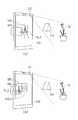
감시 결과, 카메라(121)의 동작 상태가 제1 상태이면, 상기 영상표시장치(100)는 카메라(121)를 통해 인식된 피사체 이미지가 입체 디스플레이부(152)를 기준으로 마주보는 상기 제1 및 제2 입체 오브젝트 중 적어도 하나의 표면에 투영되도록 그래픽을 제어할 수 있다(S230). 또한, 여기서, 제1 상태란, 영상표시장치(100)의 카메라(121)가 활성화 상태인 경우를 의미한다. 이와 같이, 카메라(121)가 활성화되면, 화각범위내에 있는 피사체를 촬영하여, 피사체 이미지를 획득할 수 있다.When the operation state of the
예를 들어, 도 3b를 참조하면, 영상표시장치(100)의 입체 디스플레이부(152)에 3차원 입체 영상이 출력되고 전면 카메라(121)가 활성화된 경우, 전면 카메라(121)를 통해 비치는 피사체(50)의 2D 이미지가 입체 디스플레이부(152)를 기준으로 대향되는 곳, 즉 뒤쪽에 출력된 입체 오브젝트들(322", 321") 중 적어도 하나의 표면에 출력될 수 있다. 한편, 도시된 바와 같이, 입체 디스플레이부(152)를 기준으로 피사체(50)와 동일 방향, 즉 앞쪽에 출력된 입체 오브젝트들(311, 312)에는 피사체(50)의 2D 이미지가 출력되지 않는다.For example, referring to FIG. 3B, when a three-dimensional stereoscopic image is output to the
또한, 비록 도시되지는 않았지만, 피사체(50)가 움직이는 객체이면, 상기 영상표시장치(100)는 입체 오브젝트들(322", 321")에 투영되는 이미지도 대응되게 변화하도록 그래픽을 제어할 수 있다. 예를 들어, 전면 카메라(121)를 통해 인식된 사용자의 얼굴 이미지를 입체 오브젝트들(322", 321")의 표면에 투영시킬 때, 얼굴 방향에 따라 서로 다른 이미지를 투영시킬 수 있다.Also, although not shown, if the
또한, 인식된 피사체 이미지가 투영될 입체 오브젝트의 표면은 적어도 투명 또는 반사 속성을 갖는 것을 특징으로 한다. 즉, 카메라(121)가 활성화 상태이고 피사체와 마주보는 제1 및 제2 입체 오브젝트가 존재하는 경우에도, 그러한 입체 오브젝트의 표면이 불투명 속성이면 피사체의 이미지가 표면에 투영되지 않는다.Further, the surface of the stereoscopic object onto which the recognized object image is to be projected has at least a transparent or reflective property. That is, even when the
한편, 상기 감시 결과, 카메라(121)의 동작 상태가 제2 상태이면, 상기 영상표시장치(100)는 상기 입체 디스플레이부(152)에 입사되는 광선 정보에 근거하여, 상기 제2 입체 오브젝트의 2차원 이미지가 상기 입체 디스플레이부(152)를 기준으로 마주보는 상기 제1 입체 오브젝트의 표면에 나타나도록 상기 제1 입체 오브젝트의 그래픽 정보를 제어할 수 있다(S240).On the other hand, if the operation state of the
여기서, 제2 상태란, 영상표시장치(100)의 카메라(121)가 비활성화 상태인 경우를 의미한다. 이와 같이, 카메라(121)가 비활성화 상태인 동안에는, 입체 디스플레이부(152)에 입사되는 광선의 입사방향 및 광량 등과 같은 정보에 근거하여 입체 오브젝트의 표면에 투영될 오브젝트 이미지를 결정할 수 있다.Here, the second state means a case where the
예를 들어, 도 3a를 참조하면, 영상표시장치(100)의 입체 디스플레이부(152)에 3차원 입체 영상이 출력되고 카메라(121)가 비활성화 상태이면, 입체 디스플레이부(152)에 입사되는 광선의 방향정보에 근거하여 입체 오브젝트의 표면에 나타나는 이미지가 결정된다. 도 3a에서 사용자의 시선과 광선의 방향이 일치한다고 가정할 경우, 입체 디스플레이부(152)를 기준으로 앞쪽에 출력된 제1 입체 오브젝트(311)와 제2 입체 오브젝트(312)는 각각 입체 디스플레이부(152)를 기준으로 뒤쪽에 마주보는 위치에 출력된 제3 오브젝트(321)와 제4 오브젝트(322)의 표면에 투영될 수 있다.3A, when a three-dimensional stereoscopic image is output to the
한편, 입체 오브젝트의 표면에 투명되는 이미지는 항상 2D 이미지이므로, 카메라(121)가 비활성화 상태여서 특정 입체 오브젝트의 이미지가 다른 입체 오브젝트의 표면에 투영되도록 그래픽 처리하기 위해서는, 특정 입체 오브젝트에 대한 2D 이미지를 실시간으로 생성하는 과정이 필요하다. 그런 다음, 이를 다른 입체 오브젝트의 표면의 속성(예, 거칠기, 투명 정도, 편평 정도, 모서리)에 따라 변형시키는 과정이 수반되어야 할 것이다.On the other hand, since the image that is transparent to the surface of the three-dimensional object is always a 2D image, in order for the
이를 위해, 상기 영상표시장치(100)는 특정 입체 오브젝트의 2D 이미지를 투영시킬 입체 오브젝트(이하, '투영 대상 오브젝트'라 칭함)를 2D의 가상 평면도로 전개시킬 수 있다. 그런 다음, 전개된 투영 대상 오브젝트의 각 픽셀을 좌표로 특정하고, 그에 따라 특정 입체 오브젝트의 2D 이미지가 투영될 픽셀의 좌표 정보를 생성한다. 이러한 좌표 정보에는, 픽셀 각각에 대하여 위치지정과 관련된 포지션(position)과 2D 이미지가 투영되는 방향과 관련된 법선벡터(normal vector)를 포함할 수 있다. 또한, 전개된 투영 대상 오브젝트에 투영될 2D 이미지는 밀도, 색채, 빛의 방향 등에 따라 구현되는 이미지의 명도, 선명도, 광선의 반사 효과를 상이하게 적용할 수 있다.To this end, the
이상에서 설명한 바와 같이, 본 발명의 실시예에 의하면, 증강현실에 포함된 3차원 객체의 표면이 반사속성을 갖는 경우, 대응되는 반사 이미지를 객체의 표면에 투영시키고, 이때, 카메라가 활성화 상태이면 카메라를 통해 획득된 주변의 영상이 3차원 객체의 표면에 투영되도록 함으로써 증강현실이 실제 환경의 연속인 것과 같은 사실감을 제공할 수 있다.As described above, according to the embodiment of the present invention, when the surface of the three-dimensional object included in the augmented reality has a reflection property, the corresponding reflection image is projected on the surface of the object, By allowing the surrounding image obtained through the camera to be projected onto the surface of the three-dimensional object, the augmented reality can provide a sense of reality as if it were a continuation of the actual environment.
이하, 도 4a 및 도 4b는 본 발명의 실시예에 따른 영상표시장치(100)를 기준으로 존재하는 3D 객체의 거리 및 편평도에 따라, 표면에 투영되는 이미지의 형상을 조절하는 방법을 설명하기 위한 개념도들이다. 또한, 이하에서는 영상표시장치(100)의 카메라(121)가 활성화 상태이고, 그에 따라 피사체의 이미지가 입체 오브젝트의 표면에 투영되는 경우를 전제로 설명하기로 하겠다.4A and 4B illustrate a method of adjusting a shape of an image projected on a surface according to a distance and a flatness of a 3D object existing on the basis of the
먼저, 이미지가 투영될 입체 오브젝트와 입체 디스플레이부(152)간의 이격거리에 따라 투영될 이미지의 형상이 달라질 수 있다.First, the shape of the image to be projected may vary depending on the distance between the stereoscopic object to be projected and the
이를 위해, 입체 디스플레이부(152)에 3D 입체 영상이 출력된 상태에서, 영상표시장치(100)의 산출부(181)는 상기 3D 입체 영상에 포함된 제1 및 제2 입체 오브젝트 중, 카메라(121)를 통해 획득되는 피사체의 이미지가 투영될 입체 오브젝트와 입체 디스플레이부(152)간의 거리를 산출할 수 있다.For this purpose, in a state in which the 3D stereoscopic image is output to the
그러면, 상기 제어부(180)는 상기 산출부(181)를 통해 산출된 거리값에 근거하여, 투영될 피사체의 이미지의 크기를 조절할 수 있다. 즉, 투영될 피사체의 이미지는 산출된 거리값에 비례하도록 크기 조절되어 제1 및 제2 입체 오브젝트 중 어느 하나의 표면에 투영될 수 있다. 또한, 이때, 피사체의 이미지가 투영될 입체 오브젝트의 크기에 따라, 피사체의 이미지의 전체가 표시될 수도 있고 일 부분만 표시될 수도 있다.Then, the
예를 들어, 도 4a를 참조하면, 카메라(121)를 통해 획득되는 피사체(50)의 이미지는 입체 디스플레이부(152)를 기준으로 비교적 가까이 위치한 입체 오브젝트(420)의 표면에는 이미지가 보다 크게 출력된다. 반면, 입체 디스플레이부(152)를 기준으로 비교적 멀리 위치한 입체 오브젝트(430)의 표면에는 이미지가 보다 작게 출력된다. 이와 같이, 입체 오브젝트의 표면에 나타나는 이미지에 거리감을 반영함으로써 보다 사실감 높은 반사 이미지를 표현할 수 있다.For example, referring to FIG. 4A, the image of the subject 50 obtained through the
또한, 상기 제어부(180)는 입체 오브젝트가 움직이는 경우, 그에 대응되는 거리값의 변화에 따라 표면에 투영될 피사체 이미지의 형상을 변경할 수 있다.In addition, when the stereoscopic object is moving, the
구체적으로, 상기 제어부(180)는 산출된 거리값이 감소하는 경우이면, 즉, 이미지가 투영될 입체 오브젝트가 입체 디스플레이부(152)를 향해 다가오는 경우이면, 상기 피사체 이미지의 수직 및 수평 길이를 증가하여 투영시킬 수 있다. 반면, 상기 제어부(180)는 산출된 거리값이 증가하는 경우이면, 즉 이미지가 투영될 입체 오브젝트가 입체 디스플레이부(152)를 기준으로 멀어지는 경우이면, 상기 촬영된 피사체 이미지의 수직 및 수평 길이를 감소하여 투영시킬 수 있다.Specifically, when the calculated distance value decreases, that is, when the stereoscopic object to be projected is approaching toward the
예를 들어, 도 4b를 참조하면, 입체 디스플레이부(152)를 기준으로 제1 위치에 출력된 입체 오브젝트(410_A)의 표면에 카메라(121)를 통해 획득된 피사체(410)의 이미지가 출력된다(a). 이러한 상태에서, 입체 오브젝트(410_A)가 이동하여 제1 위치에 배치되면(420_B) 입체 디스플레이부(152)와의 이격거리가 작아진만큼 표면에 투영되는 피사체(410)의 이미지의 수직 및 수평 길이를 증가시켜서 출력하도록제어한다(b). 이때, 도 4b에 도시된 바와 같이, 입체 오브젝트가 입체 디스플레이부(152)에 가까이 다가오는 경우 입체 오브젝트의 크기도 증가되므로, 크기 증가된 피사체(410) 이미지의 일부가 아닌 전체가 모두 출력될 수 있다.For example, referring to FIG. 4B, the image of the subject 410 obtained through the
한편, 도 4b에는 도시되지 않았지만, 입체 오브젝트에 투영될 피사체(410) 이미지가 이동하는 경우가 있을 수 있다. 이러한 경우, 입체 오브젝트가 움직이지 않더라도 표면에 투영되는 피사체(410) 이미지의 크기가 증가 또는 감소될 수 있다. 이때, 피사체(410) 이미지의 변경될 크기는 카메라(122)와의 이격거리에 비례하여 결정할 수 있다.Although not shown in FIG. 4B, there may be a case where the image of the subject 410 to be projected on the three-dimensional object moves. In this case, even if the three-dimensional object does not move, the size of the image of the
또한, 상기 제어부(180)는 피사체 이미지가 투영될 입체 오브젝트의 표면의 편평도 및 표준편차 정보에 따라, 투영되는 피사체 이미지의 수직 및 수평 길이를 서로 다른 비율로 증가시키거나 또는 감소시킬 수 있다. 여기서, 편평도란 구형도와는 상반된 것으로, 편평도가 작을수록 구에 가까운 형태가 되고 편평도가 커질수록 타원 형태가 된다. 또한, 여기서, 표준편차란, 이미지가 투영될 입체 오브젝트의 표면이 고르게 분포된 정도로서, 높이 표준편차가 클수록 표면이 거칠거나 기울기가 있고, 표준편차가 작을수록 표면이 매끄럽고 평평하다고 정의할 수 있다. 또한, 이러한 편평도 및 표준편차는 입체 오브젝트에 외력이 인가되면 다르게 변경될 수 있다.The
예를 들어, 도 4c를 참조하면, 피사체 이미지가 투영될 입체 오브젝트의 형상이 (a)에 도시된 바와 같이, 편평도가 큰(즉, 좌우로 퍼진 타원 형태) 경우이면 표면에 투영될 피사체 이미지의 수평 길이 비율이 증가되어 표시된다. 또한, 도 4c의 (b)에 도시된 바와 같이, 입체 오브젝트의 표면의 편평도가 작고 표준편차가 0에 가까우면 표면에 투영될 피사체 이미지에 대한 변형이 거의 없다. 한편, 도 4c의 (c)에 도시된 바와 같이, 피사체 이미지가 투영될 입체 오브젝트의 양 측면에서 안쪽으로 미는 압력이 인가되고 피사체 이미지가 중앙에 투영되는 경우이면, 표면에 투영될 피사체 이미지의 수직 길이 비율이 증가되어 표시된다.For example, referring to FIG. 4C, if the shape of a three-dimensional object to be projected is a flatness (i.e., an elliptical shape spread to left and right) as shown in (a) The horizontal length ratio is displayed increasing. Further, as shown in Fig. 4C (b), when the flatness of the surface of the three-dimensional object is small and the standard deviation is close to zero, there is almost no deformation to the object image to be projected onto the surface. On the other hand, as shown in (c) of FIG. 4C, when a pressure pushing inward from both sides of the three-dimensional object to be projected is applied and the object image is projected in the center, The length ratio is displayed increasing.
이하, 도 5는 본 발명의 실시예에 따른 영상표시장치의 기울기 변화에 따라, 3D 객체에 투영되는 이미지의 명도 및 채도를 조절하는 방법을 설명하기 위한 개념도이다.FIG. 5 is a conceptual diagram for explaining a method of adjusting brightness and chroma of an image projected on a 3D object according to a gradient change of an image display device according to an embodiment of the present invention.
이를 위해, 본 발명의 실시예에 따른 영상표시장치(100)의 감지부(140)는 입체 디스플레이부(152)의 기울기 및 기울기 변화를 더 감지할 수 있다. 또한, 상기 제어부(180)는 감지된 입체 디스플레이부(152)의 기울기 및 기울기 변화에 대응되는 광선 정보와 이와 함께 피사체 이미지가 투영될 입체 오브젝트의 속성 정보에 근거하여, 상기 투영될 피사체 이미지의 명도 및/또는 채도, 또는 투명도를 다르게 변경할 수 있다.For this, the
예를 들어, 사용자가 영상표시장치(100)를 우측으로 기울일 때와 영상표시장치(100)를 좌측으로 기울일 때, 기울임 방향 및 기울임 정도에 따라 입체 디스플레이부(152)에 인가되는 빛의 강도가 달라질 수 있다. 또한, 영상표시장치(100)를 우측으로 기울인 경우 입체 디스플레이부(152)의 A영역에만 강한 빛이 조사되었다면, 영상표시장치(100)를 좌측으로 기울인 경우에는 입체 디스플레이부(152)의 A영역에는 약한 빛이 조사되고 B영역에는 강한 빛이 조사될 수 있다. 즉, 영상표시장치(100)의 기울임 방향 및 기울임 정도에 따라 입체 디스플레이부(152)의 특정 영역에 인가되는 빛의 강도가 변화할 수 있다.For example, when the user tilts the
또한, 여기서, 피사체 이미지가 투영될 입체 오브젝트의 속성에는, 입체 오브젝트의 표면 속성뿐만 아니라, 입체 오브젝트의 전체 색상, 입체 디스플레이부(152)에 출력되는 3D 입체 영상의 배경색상과의 투명도 차이 등이 함께 고려될 수 있다. 그에 따라, 예를 들어, 빛의 강도가 동일하더라도 입체 오브젝트의 전체 색상이 어두운 경우에는 투영될 피사체 이미지의 명도 및/또는 채도 또한 어둡게 표현될 수 있다.Here, the attribute of the stereoscopic object to be projected is not limited to the surface property of the stereoscopic object but also the difference in transparency between the overall color of the stereoscopic object and the background color of the 3D stereoscopic image output to the
예를 들어, 도 5의 (a) 참조하면, 영상표시장치(100)의 카메라(121)를 통해 획득된 피사체(510)의 이미지가 입체 오브젝트(520)의 표면에 투영되는 경우, 투영되는 피사체 이미지의 명도, 채도, 및 투명도는 입체 디스플레이부(152)에 조사되는 광원(10)의 광선방향에 영향을 받는다. 즉, 도 5의 (a)에서는 광원(10)으로부터 피사체(510), 입체 디스플레이부(152), 및 입체 오브젝트(520)에 이르기까지의 광선방향 및 광선량 동일 방향을 추종함에 따라, 입체 오브젝트(520)의 표면에 투영되는 피사체 이미지가 더욱 선명하게 표현됨을 알 수 있다.5A, when the image of the
또한, 비록 도시되지는 않았지만, 영상표시장치(100)의 기울기 및 기울기 변화에 따라 광원(10)으로부터 조사된 빛이 입체 디스플레이부(152)를 지나 직접(direct)로 입체 오브젝트(520)에 도달하는 경우, 상기 제어부(180)는 투영될 피사체 이미지에 직광에 의한 눈부심 현상과 같은 효과를 출력할 수 있다. 그에 따라, 입체 오브젝트(520)에 대한 시안성은 오히려 감소될 수 있다.Although not shown, light emitted from the
한편, 도 5의 (b)에 도시된 바와 같이, 영상표시장치(100)가 일 방향으로 기울어짐에 따라, 광원(10)으로부터 조사된 빛이 입체 디스플레이부(152)를 맞고 대부분 반사되는 경우라면, 상기 제어부(180)가 상기 피사체(510) 이미지가 입체 오브젝트(520")의 표면에 흐릇하게 투영되도록 그래픽을 제어할 수 있다.5 (b), when the light emitted from the
도 6은 상술한 바와 같이 표면에 피사체 이미지가 투영된 3D 객체를 하나의 광원으로 인식하여, 이를 다른 3D 객체의 표면에 재투영시키는 방법을 설명하기 위한 개념도이다.6 is a conceptual diagram illustrating a method of recognizing a 3D object on which a subject image is projected on a surface as one light source and re-projecting the 3D object on the surface of another 3D object as described above.
이를 위해, 상기 제어부(180)는, 피사체 이미지가 투영된 적어도 하나의 입체 오브젝트를 2차 광원으로 결정할 수 있다. 그리고, 상기 제어부(180)는, 결정된 2차 광원과 직선도상에 위치한 다른 입체 오브젝트에 상기 피사체 이미지가 투영된 입체 오브젝트의 2차원 이미지를 재투영시킬 수 있다.To this end, the
예를 들어, 도 6을 참조하면, 카메라(121)를 통해 획득된 피사체(50) 이미지가 입체 디스플레이부(152)의 맞은편의 직선도상에 출력된 입체 오브젝트(610_A)에 출력된다. 그리고, 입체 오브젝트(610_A)의 표면으로부터 방출된 광선과 직선도상에 위치한 입체 오브젝트(610_B)의 표면에, 상술한 피사체 이미지가 투영된 입체 오브젝트(610_A)의 일 면(2D 이미지)이 투영된 것을 확인할 수 있다. 한편, 비록 도시되지는 않았지만, 상기 입체 오브젝트(610_B)를 3차 광원으로 하여, 입체 오브젝트(610_B)의 2D 이미지가 다른 3D 객체의 표면에 투영되도록 구현하는 것도 가능하다.6, an image of the subject 50 obtained through the
이상에서는, 영상표시장치(100)의 카메라(121)를 통해 획득된 피사체 이미지가, 사용자 의도와 관계없이 주로 광선 정보에 따라 입체 오브젝트에 투영되는 실시예들을 살펴보았다. 이하에서는, 사용자 의도에 따라 투영된 피사체 이미지를 변형시키는 실시예들을In the above, embodiments in which the object image acquired through the
도 7a 내지 도 7d는 본 발명의 실시예에 따라, 피사체 이미지가 표면에 투영된 3D 객체에 대한 사용자 입력에 근거하여, 3D 객체에 투영된 이미지를 변경하기 위한 다양한 실시예들을 설명하기로 한다.Figures 7A through 7D illustrate various embodiments for modifying an image projected on a 3D object based on user input to a 3D object projected on the surface, according to an embodiment of the present invention.
일 실시예로, 상기 제어부(180)는 피사체 이미지가 투영된 입체 오브젝트의 표면에 터치가 인가되는 것에 응답하여, 상기 피사체 이미지가 투영된 입체 오브젝트의 표면에 상기 터치에 대응되는 표시변화가 나타나도록 그래픽을 제어할 수 있다. 또는, 상기 제어부(180)는 터치가 인가된 입체 오브젝트의 표면에 투영된 피사체 이미지가 더 이상 투영되지 않도록 그래픽을 제어할 수 있다.In one embodiment, in response to a touch applied to the surface of the three-dimensional object onto which the subject image is projected, the
예를 들어, 도 7a의 (a) 참조하면, 카메라(121)를 통해 획득된 피사체(50) 이미지가 입체 디스플레이부(152)를 기준으로 마주보는 입체 오브젝트(710)의 일 표면에 투영된 상태에서, 상기 영상표시장치(100)는 피사체(50) 이미지가 투영된 면에 인가되는 터치 제스처를 감지할 수 있다. 이와 같이 입체 오브젝트(710)의 표면에 터치가 인가되면, 도 7의 (b)에 도시된 바와 같이, 입체 오브젝트(710)의 속성에 따라 표면에 투영된 피사체(50) 이미지가 변경된다. 예를 들어, 입체 오브젝트(710)가 액체 속성(예, 물)인 경우 터치가 인가된 정도에 비례하여 표면에 투영된 피사체(50) 이미지에 일렁이는 효과가 출력될 수 있다.7A, when the image of the
그리고, 상기 제어부(180) 기설정된 시간이 경과하면 이전의 이미지, 즉 다시 변경전의 피사체(50) 이미지가 입체 오브젝트(710)의 표면에 나타나도록 그래픽을 제어할 수 있다.When the predetermined time has elapsed from the
또한, 다른 일 실시예에서, 상기 제어부(180)는 기설정된 입력신호가 감지되는 것에 응답하여, 상기 피사체 이미지에 기설정된 이미지 효과가 적용된 2차원 이미지가 상기 입체 디스플레이부(152)를 기준으로 마주보는 입체 오브젝트의 표면에 투영되도록 그래픽을 제어할 수 있다.In addition, in another embodiment, in response to the detection of a predetermined input signal, the
여기서, 기설정된 입력신호란, 카메라(121)를 통해 획득된 피사체 이미지에 기설정된 특수 효과를 적용시키기 위한 제어명령의 입력신호로서, 예를 들어 입체 디스플레이부(152)에 출력된 아이콘(2D 또는 3D)에 터치를 인가하거나, 영상표시장치(100)에 구비된 특정 키를 푸시하거나, 또는 기설정된 음성명령 또는 제스처 입력을 통해 수행될 수 있다.Here, the predetermined input signal is an input signal of a control command for applying a predetermined special effect to an object image obtained through the
또한, 여기서, 기설정된 이미지 효과란 카메라(121)를 통해 획득된 피사체의 원래 이미지에 특수 효과, 예를 들어 시간의 흐름, 피사체의 특정 영역을 증가 또는 감소시키는 애니메이션 효과, 기저장된 다른 이미지의 추가, 피사체의 일 영역을 숨기거나 자르는 편집 효과 등(이에 한정되지 않음)을 적용하는 것을 의미한다.Here, the preset image effect refers to an effect of adding special effects to the original image of the subject obtained through the
예를 들어, 도 7b의 (a)에 도시된 바와 같이, 카메라(121)를 통해 획득된 피사체(70) 이미지가 입체 오브젝트(720_A)의 일 면에 투영된 상태에서 기설정된 특수효과를 적용하기 위한 입력신호가 감지되면, 입체 디스플레이부(152)의 일 영역에 '특수모드'가 표시된 아이콘(750)이 2D 또는 3D 형태로 출력된다. 그리고, 이와 함께, 입체 오브젝트(720_A)의 일 면에 투영된 피사체(70) 이미지에는 기설정된 특수 효과로, 시간의 흐름(예, 과거 또는 미래 이미지)이 적용된다. 즉, 카메라(121)를 통해 획득된 피사체(70)의 현재 모습이 아니라, 예상되는 과거 또는 미래의 모습이 입체 오브젝트의 표면에 나타나게 된다(720_A).For example, as shown in (a) of FIG. 7B, when the image of the subject 70 obtained through the
이때, 사용자가 '특수모드'임을 나타내는 아이콘(750)에 터치를 인가하면, 터치에 대응되는 촉각 효과(예, 진동 또는 시각이미지)가 출력되면서, 도 7b의 (b)와 같이, 해당 아이콘(750)이 '일반모드'가 표시된 아이콘(750")으로 변경된다. 그에 따라, 다시 피사체(70)의 원래 이미지가 입체 오브젝트의 표면에 나타날 수 있다(720_B).At this time, when a touch is applied to the
또한, 다른 일 실시예에서, 상기 제어부(180)는 영상표시장치(100)를 통해 추적되는 사용자의 시선을 따라, 피사체 이미지가 투영될 입체 오브젝트를 변경할 수 있다. 그에 따라, 사용자가 관심 있게 보는 입체 오브젝트의 표면에 피사체 이미지를 투영시키는 것이 가능해진다.Further, in another embodiment, the
이를 위해, 상기 영상표시장치(100)는, 사용자의 눈 움직임의 방향 및 패턴을 검출하기 위한 검출부(182)를 더 포함할 수 있다. 한편, 도 1a에서 상기 검출부(182)는 카메라(121) 및 제어부(180)와 별도의 구성인 것처럼 도시되었으나, 상기 검출부(182)는 카메라(121)를 통해 사용자의 시선을 추적하고, 제어부(180)를 통해 눈 움직임의 방향 및 패턴을 검출하는 것이 가능하다.To this end, the
또한, 상기 제어부(180)는, 검출부(182)를 통해 검출된 사용자의 눈 움직임의 방향 및 패턴에 근거하여, 사용자의 관심도가 높은 입체 오브젝트를 결정할 수 있다. 예를 들어, 상기 제어부(180)는 특정 입체 오브젝트에 사용자의 시선이 기설정된 시간(예, 3초) 이상 고정된 경우, 해당 입체 오브젝트에 대한 사용자의 관심이 높은 것으로 판단할 수 있다.In addition, the
그리고, 상기 제어부(180)는 결정된 입체 오브젝트가 상기 입체 디스플레이부(152)를 기준으로 피사체 이미지와 직선도상에 위치하면(즉, 입체 디스플레이부(152)를 기준으로 마주보는 경우이면), 상기 인식된 피사체 이미지가 상기 결정된 입체 오브젝트의 표면에만 투영되도록 그래픽을 제어할 수 있다.If the determined stereoscopic object is located on a straight line with the subject image on the basis of the stereoscopic display unit 152 (that is, if the stereoscopic object is facing the stereoscopic display unit 152) The object image can be projected only on the surface of the determined three-dimensional object.
예를 들어, 도 7c를 참조하면, 처음에는 피사체(70) 이미지가 입체 디스플레이부(152)를 기준으로 마주보는 제1 입체 오브젝트(720)의 표면에 투영되었으나, 사용자의 시선이 기설정된 시간 제2 입체 오브젝트(730)에 고정되는 경우, 피사체(70) 이미지가 사용자의 관심도가 높은 것으로 판된되는 제2 입체 오브젝트(730)의 일 표면으로 옮겨져서 표시될 수 있다. 이때, 제2 입체 오브젝트(730)의 속성 또한 제1 입체 오브젝트(720)와 마찬가지로 투명 또는 반사 속성인 경우이어야 할 것이다.For example, referring to FIG. 7C, the image of the subject 70 is projected on the surface of the first three-
또한, 다른 일 실시예에서, 상기 제어부(180)는 기설정된 터치 제스처에 근거하여, 카메라(121)를 통해 인식된 피사체 이미지로부터 특정 객체나 영역을 선택하는 가능하다. 이때, 기설정된 터치 제스처는, 기설정된 방식의 터치 제스처로서, 예를 들어 특정 객체나 영역에 폐곡선을 그리는 터치입력일 수 있다.Also, in another embodiment, the
이와 같이, 피사체 이미지로부터 특정 객체나 영역이 선택되면, 상기 제어부(180)는 선택된 특정 객체나 영역의 이미지만 상기 입체 디스플레이부(151)를 기준으로 마주보는 입체 오브젝트의 표면에 투영되도록 하거나, 또는 상기 특정 객체나 영역을 제외한 이미지만 상기한 입체 오브젝트의 표면에 투영되도록 그래픽을 제어할 수 있다.When a specific object or area is selected from the subject image, the
예를 들어, 도 7d를 참조하면, 도 7d의 (a)와 같이, 카메라(121)를 통해 획득된 피사체(80)에 대한 하나의 이미지가 입체 오브젝트(740)의 일 표면에 투영된 상태에서, 사용자는 투영된 이미지에 대한 터치입력을 통해 삭제하고 싶은 객체를 선택하는 것이 가능하다. 이와 같이, 사용자가 삭제하고 싶은 객체 또는 영역에 터치궤적을 그리면, 도 7d의 (b)와 같이 입체 오브젝트(740)의 일 표면에 투영된 피사체(80) 이미지로부터 선택된 객체, 예를 들어 피사체의 일부(일부 꽃들)가 사라지게 된다. 한편, 비록 도시되지는 않았지만, 상기 제어부(180)는 객체가 삭제된 영역에 기설정된 터치 제스처, 예를 들어 해당 영역을 문지르는 터치입력을 수행하면, 사라진 객체 또는 영역의 이미지가 다시 나타나도록 그래픽을 제어할 수 있다.7D, one image of the
이상에서는, 영상표시장치(100)에 구비된 하나의 카메라(121)를 이용하여 획득된 피사체 이미지를 입체 오브젝트의 일 표면에 투영시키는 실시예들을 살펴보았다. 이하에서는, 복수의 카메라를 또는 카메라의 회전을 통해, 입체 오브젝트의 표면에 피사체 이미지를 투영시키는 방법을 설명하겠다.In the above, embodiments in which the object image obtained by using one
이와 관련하여, 도 8a 내지 도 8c는 본 발명의 실시예에 따라, 카메라의 동작 상태에 따라 3D 객체에 투영된 이미지를 변경하는 방법을 설명하기 위한 개념도들이다.8A to 8C are conceptual diagrams for explaining a method of changing an image projected on a 3D object according to an operation state of a camera according to an embodiment of the present invention.
일 실시예로, 본 발명의 실시예에 따른 영상표시장치(100)는 본체의 전면 및 후면에 각각 제1 카메라(121) 및 제2 카메라(121')를 포함할 수 있다. 여기서, 제1 카메라(121)는 전면 카메라이고, 제2 카메라(121')는 후면 카메라를 의미한다. 이러한 경우, 상기 제어부(180)는 사용자 입력 또는 설정에 근거하여, 상기 제1 카메라(121) 및 제2 카메라(121')를 각각 독립적으로 동작시킬 수 있다.In one embodiment, the
구체적으로, 상기 제어부(180)는, 제1 카메라가 활성화되면, 상기 제1 카메라를 통해 인식된 제1 피사체 이미지가 상기 입체 디스플레이부(152)를 기준으로 후방의 직선도상에 위치한 입체 오브젝트의 표면에 투영되도록 그래픽을 제어할 수 있다. 또한, 상기 제어부(180)는 상기 제2 카메라가 활성화되면, 상기 제2 카메라를 통해 인식된 제2 피사체 이미지가 상기 입체 디스플레이부(152)를 기준으로 전방의 직선도상에 위치한 입체 오브젝트의 표면에 투영되도록 그래픽을 제어할 수 있다.Specifically, when the first camera is activated, the
예를 들어, 도 8a를 참조하면, (a)에 도시된 바와 같이 영상표시장치(100)의 전면 카메라(121)가 활성화되면 전면 카메라(121)를 통해 획득된 피사체(70) 이미지가 입체 디스플레이부(152)의 후방(사용자 반대방향)에 출력된 입체 오브젝트(810)의 일 표면에 투영된다. 또한, (b)에 도시된 바와 같이 영상표시장치(100)의 후방 카메라(121')가 활성화되면 후방 카메라(121')를 통해 획득된 배경 피사체(80) 이미지가 입체 디스플레이부(152)의 전방(사용자 방향)에 출력된 입체 오브젝트(820)의 일 표면에 투영된다. 또한 제1 및 제2 카메라가 동시에 활성화된 경우에는 (a) 및 (b)에 도시된 것을 조합한 것처럼 피사체(70) 및 배경 피사체(80)의 각 이미지가 대응되는 입체 오브젝트들(810, 820)에 동시에 투영될 수 있다.For example, referring to FIG. 8A, when the
또한, 다른 일 실시예에서, 본 발명의 실시예에 따른 영상표시장치(100)는 외부의 카메라를 통해 촬영된 이미지를 수신하여, 적어도 하나의 입체 오브젝트에 투영시킬 수 있다.Also, in another embodiment, the
구체적으로, 상기 제어부(180)는, 본체의 카메라(121 또는 121')와 외부의 카메라를 이용하여, 본체의 주변에 존재하는 피사체를 다양한 각도에서 인식하기 위한 상기 피사체의 제1면 이미지와 제2면 이미지를 획득할 수 있다. 그리고, 상기 제어부(180)는 획득된 제1면 및 제2면 이미지 중, 표면이 투명 또는 반사 속성을 갖는 입체 오브젝트와 마주보는 피사체 면의 이미지를 해당 입체 오브젝트의 표면에 투영시킬 수 있다.Specifically, the
즉, 제1면 이미지(예, 사용자 얼굴의 전면)에 대응되는 촬영각도와 대응되는 위치에 있는 입체 오브젝트의 표면에 제1면 이미지를 투영시키고, 이와 유사하게 제2면 이미지(예, 사용자 얼굴의 측면)에 대응되는 촬영각도와 대응되는 위치에 있는 입체 오브젝트의 표면에 제2면 이미지를 투영시킬 수 있다.That is, the first face image is projected onto the surface of the three-dimensional object at a position corresponding to the photographing angle corresponding to the first face image (e.g., the front face of the user face), and similarly, The second plane image can be projected onto the surface of the three-dimensional object at a position corresponding to the photographing angle corresponding to the photographing angle.
예를 들어, 도 8b의 (a)를 참조하면, 영상표시장치(100)의 전면 카메라(121)를 통해 사용자 얼굴의 전면 이미지(1)를 획득하고, 외부에 구비된 카메라(40)를 통해 사용자 얼굴의 측면 이미지(2)를 획득할 수 있다. 그러면, 도 8b의 (b)와 같이 반사 또는 투명 속성을 갖는 제1 및 제2 입체 오브젝트들(810, 820)에 각각 사용자 얼굴의 측면 이미지와 전면 이미지가 투영된다(810", 820").For example, referring to (a) of FIG. 8, a front image 1 of a user's face is acquired through a
또한, 다른 일 실시예에서, 상기 영상표시장치(100)의 제1 및 제2 카메라(121, 121')는, 본체의 회전에 따라 서로 다른 피사체를 동시에 인식할 수 있다.그러한 경우, 상기 제어부(180)는, 상기 제1 및 제2 카메라(121, 121')가 활성화된 상태에서 본체의 회전이 감지되는 것에 응답하여, 상기 회전에 따라 상기 제1 및 제2 카메라를 통해 획득된 서로 다른 피사체 이미지를 연결시킨 합성 이미지를 생성할 수 있다. 그리고, 상기 제어부(180)는 생성된 합성 이미지를 상기 입체 디스플레이부(152)를 기준으로 마주보는 입체 오브젝트(이때, 대부분은 전면 카메라(121)를 기준으로 입체 디스플레이부(152)와 마주보는 입체 오브젝트를 의미할 것이나, 사용자 입력을 통해 후면 카메라(121')를 기준으로 한 입체 오브젝트로 변경될 수도 있을 것이다)의 표면에 투영시킬 수 있다.In addition, in another embodiment, the first and
또한, 다른 일 실시예에서, 상기 제어부(180)는 하나의 카메라가 회전됨에 따라, 복수의 피사체 이미지를 복수의 입체 오브젝트에 투영시킬 수 있다. 구체적으로, 상기 제어부(180)는 카메라(121 또는 121')의 촬영신호가 감지되면, 입체 디스플레이부(152)에 출력된 제1 및 제2 입체 오브젝트 중, 투명 또는 반사 속성을 갖는 입체 오브젝트의 표면에 상기 카메라(121 또는 121')를 통해 촬영된 하나의 피사체 이미지를 투영시킬 수 있다.Further, in another embodiment, the
그리고, 이후 상기 본체의 회전에 따라 카메라(121 또는 121')의 회전이 감지되면, 상기 제어부(180)는 기존의 피사체 이미지의 투영 상태를 유지하면서, 상기 제1 및 제2 입체 오브젝트 중 상기 회전의 각도에 대응되는 위치에 있는 입체 오브젝트의 표면에 상기 카메라(121 또는 121')를 통해 획득된 현재의 피사체 이미지를 투영시킬 수 있다. 그에 따라, 연속된 피사체 이미지가 복수의 입체 오브젝트에 동시에 투영되는 것과 같은 효과를 얻을 수 있다.Then, when the rotation of the
예를 들어, 도 8c의 (a) 참조하면, 카메라(121)를 통해 획득된 피사체(70) 이미지가 대응되는 입체 오브젝트(810")의 표면에 투영된다. 그리고, 본체(100)의 회전에 따라 카메라(121)가 회전하면, 도 8c의 (b)와 같이, 상기 입체 오브젝트(810")의 표면에 투영되는 피사체(70) 이미지의 상태는 계속 유지되면서, 현재 촬영되는 다른 피사체(80) 이미지가 대응되는 입체 오브젝트(820")의 표면에 투영된다. 즉, 카메라(121)를 통해 이를 위해, 카메라(121)는 본체의 회전이 감지되면, 연속 촬영을 수행하고, 연속 촬영된 이미지는 순서대로 메모리(160)에 저장될 수 있다. 그리고, 과거 촬영된 이미지가 오래된 순서대로 호출되어 대응되는 각 입체 오브젝트의 표면에 투영된다.8C, an image of the
이하, 도 9는 본 발명의 실시예에 따라, 3D 객체에 중첩 투영된 이미지를 디스플레이하는 방법을 설명하기 위한 개념도이다.FIG. 9 is a conceptual diagram illustrating a method of displaying an image superimposed on a 3D object according to an embodiment of the present invention.
영상표시장치(100)의 입체 디스플레이부(152)에 출력되는 입체 오브젝트의 표면에는 영상표시장치(100)의 카메라(121 또는 121')를 통해 획득된 피사체 이미지와 다른 입체 오브젝트의 2D 이미지가 동시에 투영될 수 있다. 이러한 경우, 상기 제어부(180)는 상기 입체 오브젝트의 표면에 다른 입체 오브젝트의 2D 이미지와 카메라(121 또는 121')를 통해 획득된 피사체 이미지가 중첩표시되도록 그래픽을 제어할 수 있다.The object image obtained through the
이때, 상위에 표시될 이미지는 기설정된 기준에 따라 결정될 수 있다. 예를 들어, 상기 제어부(180)는 입체 디스플레이부(152)로부터 더 가까이 있는 객체의 이미지를 상위에 표시되도록 하거나, 또는 카메라(121)를 통해 획득된 피사체 이미지가 우선적으로 상위에 표시되도록 제어할 수 있다.At this time, the image to be displayed on the upper side may be determined according to a preset reference. For example, the
이와 같이, 입체 오브젝트의 표면에 투영되는 이미지가 복수인 경우, 상기 제어부(180)는, 복수의 이미지가 투영된 입체 오브젝트의 표면에 기설정된 터치가 인가되는 것에 응답하여, 상위에 투영된 제1 이미지를 상기 터치에 대응되는 위치로 이동하여 표시하고, 상기 제1 이미지에 의해 가려졌던 제2 이미지가 상기 입체 오브젝트의 표면의 상위에 나타나도록 그래픽을 제어할 수 있다.As described above, when a plurality of images are projected on the surface of the three-dimensional object, the
예를 들어, 도 9를 참조하면, 영상표시장치(100)의 전면 카메라(121)를 통해 획득된 피사체(70) 이미지와 입체 디스플레이부(152)의 전방에 출력된 입체 오브젝트(910)의 2D 이미지가 상기 입체 디스플레이부(152)를 기준으로 마주보는 위치에 존재하는 입체 오브젝트(920)의 표면에 중첩하여 투영될 수 있다. 이때, 입체 오브젝트(920)의 표면에는 피사체(70) 이미지 하나만 보여질 수 있다(70_A).9, an image of a subject 70 obtained through the
이때, 사용자가 복수의 이미지가 표면에 투영된 입체 오브젝트(920)에 터치를 인가한 다음, 일 방향(예, 좌측 방향)으로 플리킹을 수행하면, 상위에 표시되고 있던 피사체(70) 이미지가 플리킹에 대응되는 방향, 즉 좌측에 위치한 입체 오브젝트(930)로 이동하여 그 표면에 투영된다(903"). 그리고, 기존 입체 오브젝트(920)의 표면에는 하위에 중첩되어 있던 입체 오브젝트(910)의 2D 이미지가 투영된다.At this time, if the user applies a touch to the three-
한편, 비록 도시되지는 않았지만, 상술한 입체 디스플레이부(152)의 적어도 일부는 투명 디스플레이로 형성될 수 있다. 이러한 경우, 상기 제어부(180)는, 구비된 카메라(121)가 활성화 상태이면, 상기 카메라를 통해 인식된 피사체 이미지가 상기 투명 디스플레이를 통해 보이는 투명 또는 반사 속성을 갖는 배경객체의 표면에도 투영되도록 그래픽을 제어하는 것도 가능하다.On the other hand, although not shown, at least a part of the above-described
전술한 본 발명은, 프로그램이 기록된 매체에 컴퓨터가 읽을 수 있는 코드로서 구현하는 것이 가능하다. 컴퓨터가 읽을 수 있는 매체는, 컴퓨터 시스템에 의하여 읽혀질 수 있는 데이터가 저장되는 모든 종류의 기록장치를 포함한다. 컴퓨터가 읽을 수 있는 매체의 예로는, HDD(Hard Disk Drive), SSD(Solid State Disk), SDD(Silicon Disk Drive), ROM, RAM, CD-ROM, 자기 테이프, 플로피 디스크, 광 데이터 저장 장치 등이 있으며, 또한 캐리어 웨이브(예를 들어, 인터넷을 통한 전송)의 형태로 구현되는 것도 포함한다. 또한, 상기 컴퓨터는 단말기의 제어부(180)를 포함할 수도 있다. 따라서, 상기의 상세한 설명은 모든 면에서 제한적으로 해석되어서는 아니되고 예시적인 것으로 고려되어야 한다. 본 발명의 범위는 첨부된 청구항의 합리적 해석에 의해 결정되어야 하고, 본 발명의 등가적 범위 내에서의 모든 변경은 본 발명의 범위에 포함된다.
The present invention described above can be embodied as computer-readable codes on a medium on which a program is recorded. The computer readable medium includes all kinds of recording devices in which data that can be read by a computer system is stored. Examples of the computer readable medium include a hard disk drive (HDD), a solid state disk (SSD), a silicon disk drive (SDD), a ROM, a RAM, a CD-ROM, a magnetic tape, a floppy disk, , And may also be implemented in the form of a carrier wave (e.g., transmission over the Internet). Also, the computer may include a
Claims (20)
Translated fromKorean상기 본체에 결합되어, 제1 및 제2 입체 오브젝트를 포함하는 3차원 영상을 표시하도록 이루어지는 입체 디스플레이부;
상기 본체에 결합되어, 상기 입체 디스플레이부를 기준으로 소정범위에 존재하는 피사체를 인식하도록 이루어지는 카메라; 및
상기 카메라가 제1상태이면, 상기 카메라를 통해 인식된 피사체 이미지가 상기 입체 디스플레이부를 기준으로 마주보는 상기 제1 및 제2 입체 오브젝트 중 적어도 하나의 표면에 투영되도록 그래픽을 제어하고,
상기 카메라가 제2상태이면, 상기 입체 디스플레이부에 입사되는 광선 정보에 근거하여, 상기 제2 입체 오브젝트의 2차원 이미지가 상기 입체 디스플레이부를 기준으로 마주보는 상기 제1 입체 오브젝트의 표면에 나타나도록 상기 제1 입체 오브젝트의 그래픽 정보를 제어하는 제어부를 포함하는 것을 특징으로 하는 영상표시장치.main body;
A stereoscopic display unit coupled to the main body and configured to display a three-dimensional image including the first and second stereoscopic objects;
A camera coupled to the main body and adapted to recognize a subject in a predetermined range based on the stereoscopic display; And
Controlling a graphic so that a subject image recognized through the camera is projected on at least one surface of the first and second stereoscopic objects facing the stereoscopic display unit when the camera is in a first state,
Dimensional image of the second stereoscopic object is displayed on the surface of the first stereoscopic object facing the stereoscopic display unit on the basis of the light information incident on the stereoscopic display unit when the camera is in the second state, And a control unit for controlling graphic information of the first three-dimensional object.
상기 제1 상태는 상기 카메라가 활성화된 상태이고, 상기 제2 상태는 상기 카메라가 비활성화된 상태이고,
상기 제1 및 제2 입체 오브젝트 중, 상기 피사체 이미지가 투영되는 입체 오브젝트의 표면은 투명 또는 반사 속성을 갖는 것을 특징으로 하는 영상표시장치.The method according to claim 1,
Wherein the first state is a state in which the camera is activated, the second state is a state in which the camera is inactivated,
Wherein the surface of the three-dimensional object on which the subject image is projected has a transparent or reflective property.
상기 제1 및 제2 입체 오브젝트 중, 상기 피사체 이미지가 투영되는 입체 오브젝트와 상기 입체 디스플레이부간의 거리값을 산출하는 산출부를 더 포함하고,
상기 제어부는,
상기 산출부를 통해 산출된 거리값에 근거하여, 상기 피사체 이미지의 크기를 조절하여 투영시키는 것을 특징으로 하는 영상표시장치.The method according to claim 1,
Further comprising a calculating unit that calculates a distance value between the stereoscopic object on which the subject image is projected and the stereoscopic display unit, out of the first and second stereoscopic objects,
Wherein,
And adjusts the size of the subject image based on the distance value calculated through the calculation unit.
상기 제어부는,
상기 산출된 거리값이 감소하는 경우이면 상기 피사체 이미지의 수직 및 수평 길이를 증가하여 투영시키고,
상기 산출된 거리값이 증가하는 경우이면 상기 촬영된 피사체 이미지의 수직 및 수평 길이를 감소하여 투영시키는 것을 특징으로 하는 영상표시장치.The method of claim 3,
Wherein,
If the calculated distance value decreases, the vertical and horizontal lengths of the subject image are increased and projected,
And when the calculated distance value increases, the vertical and horizontal lengths of the photographed subject image are reduced and projected.
상기 제어부는,
상기 피사체 이미지가 투영될 입체 오브젝트 표면의 편평도 및 표준편차 정보에 따라, 투영될 피사체 이미지의 수직 및 수평 길이를 서로 다른 비율로 증가시키거나 또는 감소시키는 것을 특징으로 하는 영상표시장치.5. The method of claim 4,
Wherein,
Wherein the vertical and horizontal lengths of the object image to be projected are increased or decreased at different ratios according to the flatness and standard deviation information of the surface of the object to be projected by the object image.
상기 입체 디스플레이부의 기울기를 감지하는 감지부를 더 포함하고,
상기 제어부는,
상기 감지된 입체 디스플레이부의 기울기에 대응되는 광선 정보와 상기 피사체 이미지가 투영될 입체 오브젝트의 속성 정보에 근거하여, 상기 투영되는 피사체 이미지의 명도 및 채도를 변경하는 것을 특징으로 하는 영상표시장치.The method according to claim 1,
And a sensing unit for sensing a tilt of the stereoscopic display unit,
Wherein,
And changes the brightness and saturation of the projected subject image based on the light information corresponding to the slope of the sensed stereoscopic display unit and the attribute information of the stereoscopic object to be projected by the subject image.
상기 제어부는,
상기 피사체 이미지가 투영되는 입체 오브젝트의 표면을 2차 광원으로 결정하고, 상기 결정된 2차 광원과 직선도상에 위치한 다른 입체 오브젝트에 상기 피사체 이미지가 투영된 입체 오브젝트의 2차원 이미지를 재투영시키는 것을 특징으로 하는 영상표시장치.The method according to claim 1,
Wherein,
Dimensional image of a three-dimensional object on which the object image is projected is determined as a secondary light source, and a two-dimensional image of the three-dimensional object on which the object image is projected is re-projected to another three-dimensional object positioned on a straight line with the determined secondary light source To be displayed.
상기 제어부는,
상기 피사체 이미지가 투영된 입체 오브젝트의 표면에 터치가 인가되면, 상기 입체 오브젝트의 표면에 상기 터치에 대응되는 표시변화가 나타나거나 또는 상기 피사체 이미지가 더 이상 투영되지 않도록 제어하는 것을 특징으로 하는 영상표시장치.The method according to claim 1,
Wherein,
Wherein when the touch is applied to the surface of the three-dimensional object on which the image of the object is projected, a display change corresponding to the touch is displayed on the surface of the three-dimensional object or the image of the object is no longer projected Device.
상기 제어부는,
기설정된 입력신호가 감지되면, 상기 피사체 이미지에 기설정된 이미지 효과가 적용된 2차원 이미지가 상기 입체 디스플레이부를 기준으로 마주보는 입체 오브젝트의 표면에 투영되도록 제어하는 것을 특징으로 하는 영상표시장치.The method according to claim 1,
Wherein,
Wherein when the predetermined input signal is detected, the control unit controls the two-dimensional image to which the predetermined image effect is applied to the object image to be projected on the surface of the facing three-dimensional object based on the three-dimensional display unit.
사용자의 눈 움직임의 방향 및 패턴을 검출하는 검출부를 더 포함하고,
상기 제어부는,
상기 검출된 눈 움직임의 방향 및 패턴에 근거하여, 사용자가 관심 있어 하는 입체 오브젝트를 결정하고,
상기 결정된 입체 오브젝트가 상기 입체 디스플레이부를 기준으로 상기 피사체 이미지와 직선도상에 위치하면, 상기 인식된 피사체 이미지가 상기 결정된 입체 오브젝트의 표면에만 투영되도록 렌더링하는 것을 특징으로 하는 영상표시장치.The method according to claim 1,
Further comprising: a detection unit for detecting a direction and a pattern of a user's eye movement,
Wherein,
Determines a stereoscopic object that the user is interested in based on the detected direction and pattern of the eye movement,
And when the determined stereoscopic object is located on a straight line with the object image with reference to the stereoscopic display unit, the recognized object image is projected only on the surface of the determined stereoscopic object.
상기 제어부는,
기설정된 터치 제스처에 근거하여, 상기 카메라에 의해 인식된 피사체 이미지로부터 특정 객체나 영역을 선택하고,
상기 선택된 특정 객체나 영역의 이미지가 상기 입체 디스플레이부를 기준으로 마주보는 입체 오브젝트의 표면에 투영되도록 렌더링하는 것을 특징으로 하는 영상표시장치.The method according to claim 1,
Wherein,
Selecting a specific object or area from the subject image recognized by the camera based on the preset touch gesture,
And the image of the selected specific object or region is projected on the surface of the facing three-dimensional object based on the stereoscopic display unit.
상기 본체의 전면 및 후면에 각각 위치한 제1 및 제2 카메라를 포함하고,
상기 제어부는,
상기 제1 카메라가 활성화되면, 상기 제1 카메라를 통해 인식된 제1 피사체 이미지가 상기 입체 디스플레이부를 기준으로 후방의 직선도상에 위치한 입체 오브젝트의 표면에 투영되도록 렌더링하고,
상기 제2 카메라가 활성화되면, 상기 제1 카메라를 통해 인식된 제2 피사체 이미지가 상기 입체 디스플레이부를 기준으로 전방의 직선도상에 위치한 입체 오브젝트의 표면에 투영되도록 렌더링하는 것을 특징으로 하는 영상표시장치.The method according to claim 1,
And first and second cameras respectively disposed on front and rear surfaces of the main body,
Wherein,
Wherein when the first camera is activated, the first object image recognized through the first camera is rendered to be projected on a surface of a three-dimensional object positioned on a straight line on the back of the stereoscopic display unit,
Wherein when the second camera is activated, a second object image recognized through the first camera is projected on a surface of a three-dimensional object located on a straight line ahead of the three-dimensional display unit.
상기 제어부는,
상기 카메라와 외부의 카메라를 이용하여, 본체의 주변에 존재하는 피사체를 다양한 각도에서 인식하기 위한 상기 피사체의 제1면 이미지와 제2면 이미지를 획득하고,
상기 획득된 제1면 및 제2면 이미지 중, 표면이 투명 또는 반사 속성을 갖는 입체 오브젝트와 마주보는 피사체 면의 이미지를 해당 입체 오브젝트의 표면에 투영시키는 것을 특징으로 하는 영상표시장치.The method according to claim 1,
Wherein,
Acquiring a first side image and a second side image of the subject for recognizing a subject existing in the periphery of the main body at various angles using the camera and an external camera,
Wherein the image of the object surface facing the three-dimensional object having the transparent or reflective property of the surface of the obtained first and second surface images is projected onto the surface of the three-dimensional object.
상기 제1 및 제2 카메라는, 본체의 회전에 따라 서로 다른 피사체를 인식하도록 형성되며,
상기 제어부는, 상기 제1 및 제2 카메라 활성화된 상태에서 본체의 회전이 감지되면, 상기 회전에 따라 상기 제1 및 제2 카메라를 통해 획득된 서로 다른 피사체 이미지를 연결시킨 합성이미지를 상기 입체 디스플레이부를 기준으로 마주보는 오브젝트의 표면에 투영시키는 것을 특징으로 하는 영상표시장치.13. The method of claim 12,
The first and second cameras are configured to recognize different subjects according to rotation of the main body,
Wherein when the rotation of the main body is detected in a state in which the first and second cameras are activated, the control unit causes the composite image obtained by connecting the different object images obtained through the first and second cameras to the stereoscopic display And projecting the projected image on the surface of the facing object based on the projected image.
상기 제어부는,
상기 카메라의 촬영신호가 감지되면, 상기 제1 및 제2 입체 오브젝트 중, 투명 또는 반사 속성을 갖는 입체 오브젝트의 표면에 상기 카메라를 통해 촬영된 피사체의 이미지를 투영시키고,
이후, 상기 본체의 회전이 감지되면, 상기 피사체 이미지의 투영을 유지하면서, 상기 제1 및 제2 입체 오브젝트 중 상기 회전의 각도에 대응되는 위치에 있는 투명 또는 반사 속성을 갖는 입체 오브젝트의 표면에 상기 카메라를 통해 획득된 현재의 피사체 이미지를 투영시키는 것을 특징으로 하는 영상표시장치.The method according to claim 1,
Wherein,
Projecting an image of a subject photographed through the camera on a surface of a three-dimensional object having a transparent or reflective property among the first and second three-dimensional objects when an image pickup signal of the camera is sensed,
Thereafter, when the rotation of the main body is sensed, the surface of the three-dimensional object having a transparent or reflective property at a position corresponding to the rotation angle of the first and second stereoscopic objects, while maintaining projection of the subject image, And projecting the current object image obtained through the camera.
상기 입체 오브젝트의 표면에 투영된 피사체 이미지가 복수인 경우,
상기 제어부는,
상기 복수의 피사체 이미지가 투영된 입체 오브젝트의 표면에 기설정된 터치가 인가되는 것에 응답하여, 상기 터치에 대응되는 위치로 제1 피사체 이미지를 이동하여 표시하고, 상기 제1 피사체 이미지에 의해 가려졌던 제2 피사체 이미지가 상기 입체 오브젝트의 표면에 나타나도록 그래픽을 제어하는 것을 특징으로 하는 영상표시장치.The method according to claim 1,
When a plurality of object images projected on the surface of the three-dimensional object are present,
Wherein,
Wherein the first object image is moved and displayed in a position corresponding to the touch in response to a predetermined touch being applied to the surface of the three-dimensional object on which the plurality of object images are projected, 2 object image is displayed on the surface of the three-dimensional object.
상기 입체 디스플레이부의 적어도 일부는 투명 디스플레이로 형성되고,
상기 제어부는,
상기 카메라가 제1상태이면, 상기 카메라를 통해 인식된 피사체의 이미지가 상기 투명 디스플레이를 통해 보이는 투명 또는 반사 속성을 갖는 배경객체의 표면에도 투영되도록 그래픽을 제어하는 것을 특징으로 하는 영상표시장치.The method according to claim 1,
At least a part of the stereoscopic display part is formed as a transparent display,
Wherein,
Wherein the control unit controls the graphics so that the image of the subject recognized through the camera is projected on the surface of the background object having the transparent or reflective property visible through the transparent display if the camera is in the first state.
카메라의 동작 상태를 감시하는 단계;
상기 카메라의 동작 상태가 제1 상태이면, 상기 카메라를 통해 인식된 피사체 이미지가 디스플레이부를 기준으로 마주보는 상기 제1 및 제2 입체 오브젝트 중 적어도 하나의 표면에 투영되도록 렌더링을 수행하는 단계;
상기 카메라의 동작 상태가 제2 상태이면, 상기 디스플레이부에 입사되는 광선 정보에 근거하여, 상기 제2 입체 오브젝트의 2차원 이미지가 상기 입체 디스플레이부를 기준으로 마주보는 상기 제1 입체 오브젝트의 표면에 나타나도록 상기 제1 입체 오브젝트의 그래픽 정보를 제어하는 단계를 포함하는 것을 특징으로 하는 영상표시장치의 동작방법.Displaying three-dimensional stereoscopic images including first and second stereoscopic objects;
Monitoring an operation state of the camera;
Performing rendering so that an object image recognized through the camera is projected on at least one surface of the first and second stereoscopic objects facing the display unit when the operation state of the camera is the first state;
Dimensional image of the second stereoscopic object is displayed on the surface of the first stereoscopic object facing the stereoscopic display unit on the basis of the light information entered to the display unit when the operation state of the camera is the second state And controlling graphic information of the first stereoscopic object so that the first stereoscopic object is displayed on the display screen.
상기 제1 상태는 상기 카메라가 활성화된 상태이고, 상기 제2 상태는 상기 카메라가 비활성화된 상태이고,
상기 제1 및 제2 입체 오브젝트 중, 상기 피사체 이미지가 투영되는 입체 오브젝트의 표면은 투명 또는 반사 속성을 갖는 입체 오브젝트인 것을 특징으로 하는 영상표시장치의 동작방법.19. The method of claim 18,
Wherein the first state is a state in which the camera is activated, the second state is a state in which the camera is inactivated,
Wherein the surface of the three-dimensional object to which the subject image is projected is a three-dimensional object having a transparent or reflective property, of the first and second three-dimensional objects.
상기 제1 및 제2 입체 오브젝트 중, 상기 피사체 이미지가 투영되는 입체 오브젝트와 상기 입체 디스플레이부간의 거리값을 산출하는 단계; 및
상기 산출된 거리값에 근거하여, 상기 피사체 이미지의 크기를 조절하여 상기 입체 오브젝트의 표면에 투영시키는 단계를 더 포함하는 것을 특징으로 하는 영상표시장치의 동작방법.19. The method of claim 18,
Calculating a distance value among the first and second stereoscopic objects between the stereoscopic object on which the subject image is projected and the stereoscopic display unit; And
And adjusting the size of the object image based on the calculated distance value to project the object on the surface of the stereoscopic object.
Priority Applications (2)
| Application Number | Priority Date | Filing Date | Title |
|---|---|---|---|
| KR1020140018625AKR20150097291A (en) | 2014-02-18 | 2014-02-18 | Image display device and control method of the same |
| PCT/KR2014/001680WO2015125992A1 (en) | 2014-02-18 | 2014-02-28 | Image display device and method for controlling same |
Applications Claiming Priority (1)
| Application Number | Priority Date | Filing Date | Title |
|---|---|---|---|
| KR1020140018625AKR20150097291A (en) | 2014-02-18 | 2014-02-18 | Image display device and control method of the same |
Publications (1)
| Publication Number | Publication Date |
|---|---|
| KR20150097291Atrue KR20150097291A (en) | 2015-08-26 |
Family
ID=53878486
Family Applications (1)
| Application Number | Title | Priority Date | Filing Date |
|---|---|---|---|
| KR1020140018625AWithdrawnKR20150097291A (en) | 2014-02-18 | 2014-02-18 | Image display device and control method of the same |
Country Status (2)
| Country | Link |
|---|---|
| KR (1) | KR20150097291A (en) |
| WO (1) | WO2015125992A1 (en) |
Family Cites Families (4)
| Publication number | Priority date | Publication date | Assignee | Title |
|---|---|---|---|---|
| JP4098882B2 (en)* | 1998-05-01 | 2008-06-11 | 株式会社日立製作所 | Virtual reality generation apparatus and method |
| KR100849693B1 (en)* | 2006-12-28 | 2008-07-31 | 엔에이치엔(주) | Method and system for generating static-shadow |
| KR20110107545A (en)* | 2010-03-25 | 2011-10-04 | 에스케이텔레콤 주식회사 | Augmented reality system and method using light source recognition, and augmented reality processing apparatus for implementing the same |
| KR101547740B1 (en)* | 2011-06-01 | 2015-08-26 | 엠파이어 테크놀로지 디벨롭먼트 엘엘씨 | Structured light projection for motion detection in augmented reality |
- 2014
- 2014-02-18KRKR1020140018625Apatent/KR20150097291A/ennot_activeWithdrawn
- 2014-02-28WOPCT/KR2014/001680patent/WO2015125992A1/enactiveApplication Filing
Also Published As
| Publication number | Publication date |
|---|---|
| WO2015125992A1 (en) | 2015-08-27 |
Similar Documents
| Publication | Publication Date | Title |
|---|---|---|
| US9766775B2 (en) | Mobile terminal and method for controlling the same | |
| KR101642808B1 (en) | Mobile terminal and method for controlling the same | |
| KR20170048069A (en) | System and method for controlling the same | |
| KR20170062121A (en) | Mobile terminal and method for controlling the same | |
| KR20170006559A (en) | Mobile terminal and method for controlling the same | |
| KR20160046706A (en) | Mobile terminal and method for controlling the same | |
| KR20160131720A (en) | Mobile terminal and method for controlling the same | |
| KR20170046415A (en) | Mobile terminal and method for controlling the same | |
| KR20150142516A (en) | Glass type terminal and control method thereof | |
| KR20180079879A (en) | Mobile terminal and method for controlling the same | |
| KR20170020069A (en) | Mobile terminal and image capturing method thereof | |
| KR20160125674A (en) | Mobile terminal and method for controlling the same | |
| KR20150105845A (en) | Mobile terminal and method for controlling the same | |
| KR20180037721A (en) | Display apparatus | |
| KR20150144665A (en) | Mobile terminal | |
| KR20170019262A (en) | Mobile terminal and control method for the mobile terminal | |
| KR20170064901A (en) | Mobile device and, the method thereof | |
| KR20180000255A (en) | Mobile terminal and method for controlling the same | |
| KR20180002208A (en) | Terminal and method for controlling the same | |
| KR20170055867A (en) | Mobile terminal and method for controlling the same | |
| KR20170115863A (en) | Mobile terminal and method for controlling the same | |
| KR20180048170A (en) | Display apparatus | |
| KR20180103866A (en) | Mobile terminal and control method thereof | |
| KR20160134334A (en) | Mobile terminal and method of controlling the same | |
| KR20170011183A (en) | Mobile terminal and method for controlling the same |
Legal Events
| Date | Code | Title | Description |
|---|---|---|---|
| PA0109 | Patent application | Patent event code:PA01091R01D Comment text:Patent Application Patent event date:20140218 | |
| PG1501 | Laying open of application | ||
| PC1203 | Withdrawal of no request for examination | ||
| WITN | Application deemed withdrawn, e.g. because no request for examination was filed or no examination fee was paid |