KR20150091993A - Oil seal - Google Patents
Oil sealDownload PDFInfo
- Publication number
- KR20150091993A KR20150091993AKR1020150012641AKR20150012641AKR20150091993AKR 20150091993 AKR20150091993 AKR 20150091993AKR 1020150012641 AKR1020150012641 AKR 1020150012641AKR 20150012641 AKR20150012641 AKR 20150012641AKR 20150091993 AKR20150091993 AKR 20150091993A
- Authority
- KR
- South Korea
- Prior art keywords
- shaft
- oil
- lip
- peripheral surface
- cylindrical portion
- Prior art date
- Legal status (The legal status is an assumption and is not a legal conclusion. Google has not performed a legal analysis and makes no representation as to the accuracy of the status listed.)
- Granted
Links
- 230000002093peripheral effectEffects0.000claimsabstract7
- 239000000428dustSubstances0.000claimsabstract6
- 238000007789sealingMethods0.000claims3
Images

Classifications
- F—MECHANICAL ENGINEERING; LIGHTING; HEATING; WEAPONS; BLASTING
- F16—ENGINEERING ELEMENTS AND UNITS; GENERAL MEASURES FOR PRODUCING AND MAINTAINING EFFECTIVE FUNCTIONING OF MACHINES OR INSTALLATIONS; THERMAL INSULATION IN GENERAL
- F16J—PISTONS; CYLINDERS; SEALINGS
- F16J15/00—Sealings
- F16J15/16—Sealings between relatively-moving surfaces
- F16J15/164—Sealings between relatively-moving surfaces the sealing action depending on movements; pressure difference, temperature or presence of leaking fluid
- F—MECHANICAL ENGINEERING; LIGHTING; HEATING; WEAPONS; BLASTING
- F16—ENGINEERING ELEMENTS AND UNITS; GENERAL MEASURES FOR PRODUCING AND MAINTAINING EFFECTIVE FUNCTIONING OF MACHINES OR INSTALLATIONS; THERMAL INSULATION IN GENERAL
- F16J—PISTONS; CYLINDERS; SEALINGS
- F16J15/00—Sealings
- F16J15/16—Sealings between relatively-moving surfaces
- F16J15/32—Sealings between relatively-moving surfaces with elastic sealings, e.g. O-rings
- F16J15/3204—Sealings between relatively-moving surfaces with elastic sealings, e.g. O-rings with at least one lip
- F16J15/322—Sealings between relatively-moving surfaces with elastic sealings, e.g. O-rings with at least one lip supported in a direction perpendicular to the surfaces
- F—MECHANICAL ENGINEERING; LIGHTING; HEATING; WEAPONS; BLASTING
- F16—ENGINEERING ELEMENTS AND UNITS; GENERAL MEASURES FOR PRODUCING AND MAINTAINING EFFECTIVE FUNCTIONING OF MACHINES OR INSTALLATIONS; THERMAL INSULATION IN GENERAL
- F16J—PISTONS; CYLINDERS; SEALINGS
- F16J15/00—Sealings
- F16J15/16—Sealings between relatively-moving surfaces
- F16J15/32—Sealings between relatively-moving surfaces with elastic sealings, e.g. O-rings
- F16J15/3204—Sealings between relatively-moving surfaces with elastic sealings, e.g. O-rings with at least one lip
- F16J15/3224—Sealings between relatively-moving surfaces with elastic sealings, e.g. O-rings with at least one lip capable of accommodating changes in distances or misalignment between the surfaces, e.g. able to compensate for defaults of eccentricity or angular deviations
- F—MECHANICAL ENGINEERING; LIGHTING; HEATING; WEAPONS; BLASTING
- F16—ENGINEERING ELEMENTS AND UNITS; GENERAL MEASURES FOR PRODUCING AND MAINTAINING EFFECTIVE FUNCTIONING OF MACHINES OR INSTALLATIONS; THERMAL INSULATION IN GENERAL
- F16J—PISTONS; CYLINDERS; SEALINGS
- F16J15/00—Sealings
- F16J15/16—Sealings between relatively-moving surfaces
- F16J15/32—Sealings between relatively-moving surfaces with elastic sealings, e.g. O-rings
- F16J15/3204—Sealings between relatively-moving surfaces with elastic sealings, e.g. O-rings with at least one lip
- F16J15/3232—Sealings between relatively-moving surfaces with elastic sealings, e.g. O-rings with at least one lip having two or more lips
Landscapes
- Engineering & Computer Science (AREA)
- General Engineering & Computer Science (AREA)
- Mechanical Engineering (AREA)
- Sealing With Elastic Sealing Lips (AREA)
Abstract
Translated fromKoreanDescription
Translated fromKorean본 발명은 축과 축구멍 사이를 밀봉하는 오일 실에 관한 것이다.
The present invention relates to an oil seal which seals between a shaft and a shaft yoke.
현재, 크랭크 케이스 내압이 비교적 낮은 엔진에는, 마찰을 낮게 함으로써 저항력이 저하된 립 실(lip seal)의 사용이 추장(推奬)되고 있다. 여기서, 오일 실의 직경방향의 힘은, 립 실과 축의 접촉을 유지하기에 충분하면서도, 마찰이 최소한으로 되도록 충분히 낮게 된다. 그렇지만, 터보식이나 슈퍼차저(supercharger)식 등의 과급(過給) 엔진의 일부에서는, 크랭크 케이스 내압이 부압(負壓)으로 됨으로써, 립 실이 축과의 접촉을 유지하지 못하게 되는 일이 있다. 이에 따라, 대기 측으로부터 크랭크 케이스 내로 향하는 공기의 흐름이 야기된다. 이 공기의 흐름은, 밀봉 립(sealing lip), 오일 및 축과의 상호작용에 의해, 수요자에게는 불쾌한 이음(異音)(소리 정도의 높은 이음)을 발생시킬 수 있다. 따라서, 오일 측에 부압이 발생해도 축과의 접촉을 유지할 수 있는, 저마찰의 오일 실이 요망되고 있다.
At present, the use of a lip seal whose resistance is lowered by lowering friction is recommended for an engine having a relatively low crankcase withstand pressure. Here, the force in the radial direction of the oil chamber is sufficient enough to maintain contact between the lip and the shaft, and sufficiently low so that the friction is minimized. However, in a part of a supercharging engine such as a turbocharger or a supercharger type, the inner pressure of the crankcase becomes a negative pressure, so that the lip seal may not maintain contact with the shaft . This causes a flow of air from the atmospheric side into the crankcase. This air flow can cause uncomfortable noise (high noise level) to the consumer due to interaction with the sealing lip, oil and shaft. Therefore, a low-friction oil chamber capable of maintaining contact with the shaft even when negative pressure is generated on the oil side is desired.
본 발명의 목적은, 축과 축구멍 사이를 밀봉하여 대기 측과 오일 측을 갈라놓는 오일 실에 있어서, 오일 측에 부압이 발생해도 축과의 접촉을 유지하는 것이 가능한 오일 실을 제공함에 있다.
An object of the present invention is to provide an oil chamber which seals between a shaft and a shaft hole and separates the atmosphere side and the oil side so that contact with the shaft can be maintained even if a negative pressure is generated on the oil side.
본 발명은, 상기 과제를 해결하기 위해 이하의 수단을 채용했다.The present invention employs the following means to solve the above problems.
즉, 본 발명에 따른 오일 실은,That is, in the oil chamber according to the present invention,
축과 축구멍 사이를 밀봉하여 대기 측과 오일 측을 갈라놓는 오일 실로서,An oil seal separating the atmosphere from the oil side by sealing between the shaft and the shaft bore,
상기 축구멍의 내주면에 대해 고정되는 고정부와,A fixing part fixed to an inner circumferential surface of the shaft yoke,
상기 고정부로부터 축방향이고 또한 직경방향 내측으로 연장되는 벨로우즈부와,A bellows portion extending axially and radially inward from the fixed portion,
상기 벨로우즈부의 직경방향 내측의 끝(端)으로부터 상기 대기 측으로 향하여 축방향으로 연장되는 원통부와,A cylindrical portion extending in the axial direction from the radially inner end of the bellows portion toward the atmosphere side,
상기 원통부의 상기 대기 측의 끝으로부터, 직경방향 내측으로 또한 상기 오일 측으로 향하여 축방향으로 연장되는, 상기 축의 외주면에 슬라이딩 자재로 밀착하는 눕혀진 밀봉 립과,A lying lip sealed in sliding contact with the outer circumferential surface of the shaft, extending axially inward from the atmospheric side end of the cylindrical portion toward the oil side in the radial direction,
상기 원통부의 상기 대기 측의 끝으로부터, 상기 대기 측으로 향하여 축방향으로 연장되는 더스트 립을 구비한다.And a dust lip extending axially from the atmospheric side end of the cylindrical portion toward the atmospheric side.
이 구성에 의하면, 벨로우즈부는 축방향과 직경방향의 쌍방으로 연장하고 있기 때문에, 직경방향 내측으로 향하여 휘어지는 것이 가능하게 된다. 이에 따라, 오일 측에 부압이 발생하여 밀봉 립을 축으로부터 직경방향으로 들어 올리는 힘이 작용한 때에는, 벨로우즈부의 형상에 의해 당해 힘과 상쇄되는, 밀봉 립과 축의 접촉을 유지하는 힘이 원통부에 작용한다. 이로써, 오일 측에 부압이 발생해도, 오일 실과 축의 접촉을 유지하는 것이 가능하게 된다.According to this configuration, since the bellows portion extends in both the axial direction and the radial direction, it is possible to bend toward the radially inward direction. As a result, when a negative pressure is generated on the oil side and a force for lifting the sealing lip from the shaft in the radial direction acts, a force for holding the contact between the sealing lip and the shaft, which is canceled from the force by the shape of the bellows portion, . Thereby, even if a negative pressure is generated on the oil side, it is possible to maintain the contact between the oil chamber and the shaft.
여기서, 상기 오일 측에, 상기 밀봉 립을 상기 축의 외주면으로부터 들어 올리기에 충분한 부압이 발생하고 있을 때에, 상기 원통부의 상기 대기 측의 끝이 상기 더스트 립을 상기 축의 외주면에 밀착시키도록 휘어지도록 구성해도 좋다.Here, even when the dust lip is bent so as to be brought into close contact with the outer circumferential surface of the shaft, the end of the atmospheric side of the cylindrical portion may be bent so that the dust lip is brought into close contact with the outer circumferential surface of the shaft when a sufficient negative pressure for lifting the sealing lip from the outer circumferential surface of the shaft is generated good.
이 구성에 의하면, 부압이 발생한 때에는, 더스트 립이 축의 외주면에 밀착하기 때문에, 오일 실의 내주 측을 통과하는 공기의 흐름을 발달시키지 않도록 할 수 있다. 한편, 오일 실은, 오일 측에 발생한 진공에 의해 요동됨으로써, 더스트 립이 축에 접촉하여 공기의 흐름을 밀봉하는 것이 가능하도록, 충분히 유연하게 구성되면 좋다. 또, 더스트 립은 밀봉 립이 완전히 들어 올려지기 전에 축에 대해 접촉하도록 구성되면 좋다.According to this structure, when the negative pressure is generated, the dust lip is brought into close contact with the outer circumferential surface of the shaft, so that the flow of air passing through the inner circumferential side of the oil chamber can be prevented from developing. On the other hand, the oil chamber may be sufficiently flexible so as to be able to seal the flow of air by contacting the dust lip with the shaft by pivoting by the vacuum generated on the oil side. The dust lip may be configured to contact the shaft before the seal lip is completely lifted.
한편, 상기 오일 측에 부압이 발생하고 있지 않은 경우는, 상기 밀봉 립이 상기 축의 외주면에 밀착함과 더불어, 상기 더스트 립이 상기 축의 외주면으로부터 직경방향으로 이간하고 있고,On the other hand, when no negative pressure is generated on the oil side, the seal lip is brought into close contact with the outer peripheral surface of the shaft, and the dust lip is separated from the outer peripheral surface of the shaft in the radial direction,
상기 오일 측에 부압이 발생하여 상기 밀봉 립을 상기 축의 외주면으로부터 들어 올리는 힘이 작용한 경우는, 상기 원통부의 상기 대기 측의 끝이, 상기 더스트 립을 상기 축의 외주면에 밀착시키도록, 휘어지도록 하면 좋다.When a negative pressure is generated on the oil side and a force for lifting the seal lip from the outer peripheral surface of the shaft acts, the atmospheric side end of the cylindrical portion is bent so as to bring the dust lip into close contact with the outer peripheral surface of the shaft good.
또, 상기 밀봉 립이 내주 측에 펌프 홈을 구비해도 좋다.The sealing lip may have a pump groove on the inner circumferential side.
이에 따라, 밀봉 립과 축 사이의 접촉면의 윤활(潤滑)이 유지된다.
Thus, lubrication of the contact surface between the seal lip and the shaft is maintained.
이상 설명한 바와 같이, 본 발명에 의하면, 축과 축구멍 사이를 밀봉하여 대기 측과 오일 측을 갈라놓는 오일 실에 있어서, 오일 측에 부압이 발생해도 축과의 접촉을 유지하는 것이 가능한 오일 실이 제공된다.
As described above, according to the present invention, in the oil chamber which seals between the shaft and the shaft hole and separates the atmosphere side and the oil side, an oil chamber capable of maintaining contact with the shaft even when a negative pressure is generated on the oil side / RTI >
도 1은 본 발명의 실시예에 따른 오일 실의 구성을 나타내는 모식적 단면도로, 통상의 사용조건 하에서의 상태를 나타내고 있다.
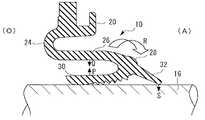
도 2는 본 발명의 실시예에 따른 오일 실의 모식적 단면도로, 오일 측에 부압이 발생하고 있을 때의 상태를 나타내고 있다.1 is a schematic cross-sectional view showing the configuration of an oil chamber according to an embodiment of the present invention, and shows a state under normal use conditions.
2 is a schematic cross-sectional view of an oil chamber according to an embodiment of the present invention, showing a state when a negative pressure is generated on the oil side.
이하에 도면을 참조해서, 이 발명을 실시하기 위한 형태를, 실시예에 기초해서 예시적으로 상세히 설명한다. 다만, 이 실시예에 기재되어 있는 구성부품의 치수, 재질, 형상, 그 상대적 배치 등은, 특별히 특정적인 기재가 없는 한은, 이 발명의 범위를 그것들에만 한정하는 취지의 것은 아니다. 본 실시예에 따른 오일 실은, 엔진의 크랭크 케이스 내의 공간을 밀봉하기 위해 사용되는 것이다.BEST MODE FOR CARRYING OUT THE INVENTION Hereinafter, embodiments for carrying out the present invention will be described in detail by way of examples on the basis of the drawings. However, the dimensions, materials, shapes, relative arrangements and the like of the constituent parts described in this embodiment are not intended to limit the scope of the present invention to them unless otherwise specified. The oil chamber according to the present embodiment is used for sealing the space in the crankcase of the engine.
이하의 설명에 있어서, 어떤 요소나 층이 다른 요소나 층의 「위에 있다」, 「밀착한다」 등으로 표현되어 있는 경우는, 그 요소나 층은 직접적으로 다른 요소나 층의 위에 있다거나, 직접적으로 밀착하고 있다고 해도 좋고, 혹은 개재(介在)하는 요소나 층이 사이에 존재해도 좋다.
In the following description, when an element or layer is referred to as being "on,""in close proximity to" another element or layer, the element or layer is directly on another element or layer, May be in close contact with each other, or intervening elements or layers may be present.
(실시예)(Example)
도 1을 참조하여 본 발명의 실시예에 따른, 에너지 절약형의 오일 실(10)에 대해 설명한다. 오일 실(10)은, 축(16)과, 하우징(14)의 축구멍(12) 사이를 밀봉하여, 대기 측(A)과 오일 측(O)을 사이를 떼어 두도록 설계되어 있다. 오일 실(10)은, 축구멍(12)의 내주면에 대해 고정되는 고정부(20)를 구비하고 있다. 본 실시예에 있어서는, 고정부(20)는 축구멍(12)의 내주면에 고정된 금속으로 이루어진 환상부재(22)에 대해 설비되어 있다. 한편, 고정부(20)와 환상부재(22)의 형상은 도시된 형상 이외의 형상이어도 좋다. 또, 환상부재(22)를 설치하지 않고, 고정부(20)가 축구멍(12)의 내주면에 대해 직접적으로 밀착하도록 구성해도 좋다.An energy-saving
오일 실(10)은, 고정부(20)로부터 축방향이고 또한 직경방향 내측으로 연장되는 벨로우즈(bellows)부(24)를 구비하고 있다. 벨로우즈부(24)는, 축방향과 직경방향의 쌍방으로 연장하고 있기 때문에, 직경방향 내측으로 향하여 휘어지는 것이 가능하게 된다. 또, 오일 실(10)은 벨로우즈부(24)의 직경방향 내측의 끝(端; 25)으로부터 대기 측(A)으로 향하여 축방향으로 연장되는 원통부(26)를 구비하고 있다. 원통부(26)의 대기 측(A)의 끝에는 피봇부(28)가 형성되어 있다. 그리고, 오일 실(10)은, 피봇부(28)로부터, 직경방향 내측으로 또한 오일 측(O)으로 향하여 축방향으로 연장되는, 축(16)의 외주면에 슬라이딩 자재로 밀착하는 눕혀진 밀봉 립(30)을 구비하고 있다. 더욱이, 오일 실(10)은, 원통부(26)의 피봇부(28)로부터, 직경방향 내측으로 또한 대기 측(A)으로 향하여 축방향으로 연장되는 더스트 립(dust lip; 32)을 구비하고 있다. 피봇부(28)는 원통부(26), 밀봉 립(30), 더스트 립(32)의 어느 것보다도 두껍게 구성되어 있다. 이에 따라, 피봇부(28)를, 용이하게 변형하는 형상이 아니라, 원통부(26)에 대해 선회(旋回)하도록(구부러지도록) 구성할 수 있다.The
밀봉 립(30)은, 직경방향 내측에 복수의 펌프 홈(34)을 구비하고 있다. 펌프 홈(34)은, 밀봉 립(30)과 축(16) 사이의 접촉면의 윤활(潤滑)이 유지되도록 설계되어 있다. 오일 측(O)에 부압이 발생하고 있지 않거나, 혹은 발생하고 있다고 해도 극히 근소한 사용조건 하에서는, 도 1에 나타낸 바와 같이 밀봉 립(30)이 축(16)에 밀착하는데 반하여, 더스트 립(32)은 축(16)으로부터 이간된다. 밀봉 립(30)은 축(16)에 대해 저마찰로 밀착하도록 구성되어 있다. 이에 대해, 오일 측(O)에 부압이 발생하는 사용조건 하에서는, 도 2에 나타낸 바와 같이 이 부압에 의해 밀봉 립(30)을 축(16)으로부터 들어 올리는 것과 같은 힘(도 2 중의 화살표 P)이 작용한다. 한편, 벨로우즈부(24)의 형상에 따라, 당해 힘과 상쇄되는, 축(16)에 대한 밀봉 립(30)의 접촉을 유지하는 힘(도 2 중의 화살표 Q)이 원통부(26)에 작용한다. 더욱이, 오일 측(O)이 진공상태로 된 때에는, 오일 실(10)은 도 2 중의 화살표 R로 나타낸 바와 같이, 실 전체가 피봇부(28) 둘레로 요동하도록 설계되어 있다. 즉, 오일 실(10)은, 오일 측(O)에 발생한 진공에 의해 요동됨으로써, 더스트 립(32)이 축(16)에 접촉하여 공기의 흐름을 밀봉하는 것이 가능하도록, 충분히 유연하게 구성되어 있다. 또, 밀봉 립(30)이 완전히 들어 올려지기 전에 축(16)에 대해 접촉하도록 구성되어 있다. 이에 따라, 더스트 립(32)을 축(16)에 대해 접촉시켜(도 2 중의 화살표 S), 오일 실(10)의 내주 측을 통과하는 공기의 흐름을 발달시키지 않도록 할 수 있다.The seal lip (30) has a plurality of pump grooves (34) radially inward. The
실 재료의 구성으로서는, 플라스틱, 고무나 PTFE(Polytetrafluoroethylene, 폴리테트라플루오르에틸렌), TPE(열가소성 엘라스토머), TPV(가교형 열가소성 엘라스토머) 등의 폭넓은 엘라스토머를 이용할 수 있다.
As the composition of the seal material, a wide range of elastomers such as plastics, rubber, PTFE (Polytetrafluoroethylene), TPE (thermoplastic elastomer) and TPV (cross-linked thermoplastic elastomer) can be used.
10 : 오일 실12 : 축구멍
14 : 하우징16 : 축
20 : 고정부24 : 벨로우즈부
26 : 원통부28 : 피봇부
30 : 밀봉 립32 : 더스트 립
A : 대기 측O : 오일 측10: oil chamber 12: soccer yoke
14: housing 16:
20: Fixing portion 24: Bellows portion
26: cylindrical portion 28: pivot portion
30: seal lip 32: dust lip
A: Atmospheric side O: Oil side
Claims (4)
Translated fromKorean상기 축구멍의 내주면에 대해 고정되는 고정부와,
상기 고정부로부터 축방향이고 또한 직경방향 내측으로 연장되는 벨로우즈부와,
상기 벨로우즈부의 직경방향 내측의 끝으로부터 상기 대기 측으로 향하여 축방향으로 연장되는 원통부와,
상기 원통부의 상기 대기 측의 끝으로부터, 직경방향 내측으로 또한 상기 오일 측으로 향하여 축방향으로 연장되는, 상기 축의 외주면에 슬라이딩 자재로 밀착하는 눕혀진 밀봉 립과,
상기 원통부의 상기 대기 측의 끝으로부터, 상기 대기 측으로 향하여 축방향으로 연장되는 더스트 립을 구비한 것을 특징으로 하는 오일 실.
An oil seal separating the atmosphere from the oil side by sealing between the shaft and the shaft bore,
A fixing part fixed to an inner circumferential surface of the shaft yoke,
A bellows portion extending axially and radially inward from the fixed portion,
A cylindrical portion extending in the axial direction from the radially inner end of the bellows portion toward the atmosphere side,
A lying lip sealed in sliding contact with the outer circumferential surface of the shaft, extending axially inward from the atmospheric side end of the cylindrical portion toward the oil side in the radial direction,
And a dust lip extending axially from said atmospheric side end of said cylindrical portion toward said atmospheric side.
The dust collecting apparatus as set forth in claim 1, wherein, when a sufficient negative pressure is generated on the oil side to lift the sealing lip from the outer peripheral surface of the shaft, the atmospheric side end of the cylindrical portion closely contacts the outer peripheral surface of the shaft Wherein the oil chamber is bent.
상기 오일 측에 부압이 발생하여 상기 밀봉 립을 상기 축의 외주면으로부터 들어 올리는 힘이 작용한 경우는, 상기 원통부의 상기 대기 측의 끝이 상기 더스트 립을 상기 축의 외주면에 밀착시키도록 휘어지는 것을 특징으로 하는 오일 실.
The dust lip according to claim 1 or 2, wherein when no negative pressure is generated on the oil side, the seal lip closely contacts the outer peripheral surface of the shaft, and the dust lip is spaced apart from the outer peripheral surface of the shaft in the radial direction ,
And the atmospheric side end of the cylindrical portion is bent so as to bring the dust lip into close contact with the outer peripheral surface of the shaft when a negative pressure is generated at the oil side and a force for lifting the sealing lip from the outer peripheral surface of the shaft acts. Oil seal.
The oil chamber according to claim 1 or 2, wherein the seal lip has a pump groove on an inner circumferential side.
Applications Claiming Priority (4)
| Application Number | Priority Date | Filing Date | Title |
|---|---|---|---|
| US14/172,329 | 2014-02-04 | ||
| US14/172,329US9695937B2 (en) | 2014-02-04 | 2014-02-04 | Energy saving seal with vacuum induced counter-balance and rocking feature |
| JP2014161917AJP6405777B2 (en) | 2014-02-04 | 2014-08-07 | Oil seal |
| JPJP-P-2014-161917 | 2014-08-07 |
Publications (2)
| Publication Number | Publication Date |
|---|---|
| KR20150091993Atrue KR20150091993A (en) | 2015-08-12 |
| KR102296674B1 KR102296674B1 (en) | 2021-09-01 |
Family
ID=53754483
Family Applications (1)
| Application Number | Title | Priority Date | Filing Date |
|---|---|---|---|
| KR1020150012641AActiveKR102296674B1 (en) | 2014-02-04 | 2015-01-27 | Oil seal |
Country Status (3)
| Country | Link |
|---|---|
| US (1) | US9695937B2 (en) |
| JP (1) | JP6405777B2 (en) |
| KR (1) | KR102296674B1 (en) |
Families Citing this family (2)
| Publication number | Priority date | Publication date | Assignee | Title |
|---|---|---|---|---|
| US9759330B2 (en)* | 2014-02-04 | 2017-09-12 | Freudenberg-Nok General Partnership | Energy saving seal with rocking dust lip |
| US10240678B2 (en) | 2016-10-18 | 2019-03-26 | Tenneco Inc. | Radial shaft seal assembly with axially adaptive debris exclusion face lip and oil seal face lip |
Citations (11)
| Publication number | Priority date | Publication date | Assignee | Title |
|---|---|---|---|---|
| KR19980045671U (en)* | 1996-12-27 | 1998-09-25 | 박병재 | Oil seal for oil sealing on eccentric shaft |
| US20050098959A1 (en)* | 2003-11-10 | 2005-05-12 | Kaco Gmbh + Co. Kg | Sealing Ring, Especially Radial Shaft Seal |
| KR20080053603A (en)* | 2006-12-11 | 2008-06-16 | 현대자동차주식회사 | Oil seal with enhanced leakage prevention |
| US20080143055A1 (en)* | 2006-12-13 | 2008-06-19 | Skf Usa Inc. | Seal with guide member |
| KR20090042547A (en)* | 2007-10-26 | 2009-04-30 | 현대자동차주식회사 | Radial oil seal structure |
| KR20090127162A (en)* | 2007-03-09 | 2009-12-09 | 페더럴-모걸 코오포레이숀 | How to install the dynamic shaft seal and dynamic shaft seal |
| US7770897B2 (en)* | 2005-02-24 | 2010-08-10 | Freudenberg-Nok General Partnership | Dynamic seal |
| KR20110112183A (en)* | 2010-04-06 | 2011-10-12 | 엔오케이 가부시키가이샤 | Energy saving seal with main lip and dust lip hinge points |
| KR20110113181A (en)* | 2009-01-28 | 2011-10-14 | 페더럴-모걸 코오포레이숀 | Radial shaft seal, radial shaft seal assembly and installation method |
| JP2012211701A (en)* | 2005-09-12 | 2012-11-01 | Federal Mogul Corp | Radial seal, and method of making |
| JP5225987B2 (en)* | 2006-06-21 | 2013-07-03 | トレルボルグ シーリング ソリューションズ ジャーマニー ゲーエムベーハー | Seal and seal configuration |
Family Cites Families (128)
| Publication number | Priority date | Publication date | Assignee | Title |
|---|---|---|---|---|
| US2482029A (en) | 1946-08-05 | 1949-09-13 | Noel S Reynolds | Seal |
| US2635907A (en) | 1950-11-13 | 1953-04-21 | Brummer Mfg Corp | Seal for shafts |
| US2697623A (en) | 1951-02-06 | 1954-12-21 | Nat Motor Bearing Co Inc | Fluid seal construction |
| US2736583A (en) | 1951-06-21 | 1956-02-28 | Gen Motors Corp | Fluid seal |
| US2743950A (en) | 1951-07-12 | 1956-05-01 | Nat Motor Bearing Co Inc | Shaft seal |
| US2758853A (en) | 1952-11-07 | 1956-08-14 | Gen Tire & Rubber Co | Journal box seal |
| US2797944A (en) | 1952-12-05 | 1957-07-02 | Gen Motors Corp | Fluid seal |
| US2736585A (en) | 1952-12-05 | 1956-02-28 | Gen Motors Corp | Fluid seal |
| US2731284A (en) | 1952-12-05 | 1956-01-17 | Garlock Packing Co | Sealing devices |
| US2736586A (en) | 1952-12-05 | 1956-02-28 | Gen Motors Corp | Fluid seal |
| US3005648A (en) | 1958-03-19 | 1961-10-24 | Federal Mogul Bower Bearings | Dual lip seal |
| US3049356A (en) | 1958-06-02 | 1962-08-14 | Borg Warner | Shaft oil seal means with deflector |
| US3356376A (en) | 1964-05-11 | 1967-12-05 | Federal Mogul Corp | Axle seal |
| US3477730A (en) | 1965-03-26 | 1969-11-11 | Chicago Rawhide Mfg Co | Shaft seal |
| US3554566A (en) | 1968-07-26 | 1971-01-12 | Gen Motors Corp | Seal assembly for relatively rotatable members |
| US3572734A (en) | 1968-09-27 | 1971-03-30 | John E Holt | Shaft seal |
| DE6916004U (en) | 1969-04-22 | 1969-08-28 | Stephan Und Soehne A | CONTAINER, BOWL OR THE LIKE. WITH A SHAFT SEAL |
| US3623738A (en) | 1970-03-11 | 1971-11-30 | Unity Railway Supply Co Inc | Rear seal |
| US3785660A (en) | 1970-10-15 | 1974-01-15 | Republic Ind Corp | Seal |
| US3827703A (en) | 1971-07-23 | 1974-08-06 | Chicago Rawhide Mfg Co | Radial shaft seal with positive garter spring retention |
| GB1432143A (en) | 1972-06-29 | 1976-04-14 | Angus George Co Ltd | Shaft seals optical projection systems |
| US3822890A (en) | 1973-01-15 | 1974-07-09 | Roulements Soc Nouvelle | Bearing seals |
| US3921990A (en) | 1973-06-18 | 1975-11-25 | Angus George Co Ltd | Shaft seals |
| US3941396A (en) | 1974-08-15 | 1976-03-02 | Caterpillar Tractor Co. | Seal for rotating means |
| FR2295319A1 (en) | 1974-10-21 | 1976-07-16 | Paulstra Sa | IMPROVEMENTS TO GASKETS OR SIMILAR GASKETS |
| US4038359A (en) | 1975-01-27 | 1977-07-26 | Garlock Inc. | Method of making a shaft seal with dual lip |
| US4132421A (en) | 1975-02-14 | 1979-01-02 | Federal-Mogul Corporation | Shaft seal |
| US4021049A (en) | 1975-12-15 | 1977-05-03 | Caterpillar Tractor Co. | Adjustable lip type seal for a crankshaft |
| US4037849A (en) | 1976-02-11 | 1977-07-26 | The Mechanex Corporation | Lubricant seal |
| JPS53109062A (en) | 1977-03-03 | 1978-09-22 | Yoshio Arai | Oil seal of fluorine resin incorporating elastic body such as spring* and packing or the like* and manufacturing method thereof |
| US4106781A (en) | 1977-04-28 | 1978-08-15 | Garlock Inc. | Unitized, grease-purgeable seal |
| US4270762A (en) | 1977-05-03 | 1981-06-02 | Coaltek Corporation | Disperser seal and method |
| GB1600515A (en) | 1978-04-18 | 1981-10-14 | Glacier Metal Co Ltd | Annular seal |
| US4226428A (en) | 1978-07-13 | 1980-10-07 | Paptzun George J | Flexible seal and groove assembly |
| US4229010A (en) | 1978-12-20 | 1980-10-21 | Bellofram Corporation | Self-aligning shaft seal |
| US4208060A (en) | 1979-01-15 | 1980-06-17 | Bellofram Corporation | Sealed shaft |
| US4274641A (en)* | 1979-10-29 | 1981-06-23 | Garlock Inc. | Shaft seal and method |
| US4300778A (en) | 1980-02-07 | 1981-11-17 | International Packings Corporation | High pressure shaft seal |
| GB2072278B (en) | 1980-03-18 | 1983-10-05 | Angus George Co Ltd | Rotary fluid seals |
| US4344631A (en) | 1980-11-18 | 1982-08-17 | Mechanical Technology Incorporated | Pressure insensitive lip seal |
| DE3106318C1 (en) | 1981-02-20 | 1982-09-30 | Howaldtswerke-Deutsche Werft Ag Hamburg Und Kiel, 2300 Kiel | Sealing arrangement with cooling device |
| GB2121893B (en) | 1981-10-21 | 1985-05-22 | Mitsubishi Rubber | Sealing arrangements for bearings |
| DE3227969C2 (en) | 1982-07-27 | 1985-05-30 | Uni-Cardan Ag, 5200 Siegburg | Sealing arrangement |
| US4474484A (en) | 1982-08-02 | 1984-10-02 | Roto-Master Inc. | Semi-floating bearing |
| GB2129069B (en) | 1982-10-25 | 1986-01-15 | Angus & Company Limited George | Shaft seal |
| US4531747A (en) | 1982-11-01 | 1985-07-30 | Nippon Oil Seal Industry Co., Ltd. | Extended wear annular oil seal |
| DE3307470C1 (en) | 1983-03-03 | 1991-03-28 | Fa. Carl Freudenberg, 6940 Weinheim | Sealing ring |
| US5004248A (en) | 1983-08-25 | 1991-04-02 | Garlock Inc. | Unitized seal with unitizing joint remote from seal lip |
| US4531748A (en) | 1984-03-30 | 1985-07-30 | Chicago Rawhide Manufacturing Co. | Fluid seal with unitary wear sleeve element |
| US4643436A (en) | 1984-03-30 | 1987-02-17 | Chicago Rawhide Mfg. Co. | Fluid seals with unitary wear sleeve elements |
| IT1184735B (en) | 1984-03-31 | 1987-10-28 | Skf Gmbh | WATERPROOF ROLLING BEARING |
| JPS60184461U (en) | 1984-05-17 | 1985-12-06 | エヌオーケー株式会社 | oil seal |
| JPS61171607A (en) | 1985-01-24 | 1986-08-02 | Tokai Kogyo Kk | Sealing component part for automobile |
| US4585236A (en) | 1985-03-14 | 1986-04-29 | Morgan Construction Company | Double jointed coolant seal |
| US5244215A (en) | 1985-05-10 | 1993-09-14 | Chicago Rawhide Manufacturing Company | Rotary shaft seal with retractable excluder lip |
| DE3524461A1 (en) | 1985-07-09 | 1987-01-22 | Kaco Gmbh Co | RADIAL SHAFT SEAL |
| NL8502033A (en) | 1985-07-15 | 1987-02-02 | Ihc Holland Nv | SHAFT SEAL. |
| FR2585103B1 (en) | 1985-07-18 | 1989-06-02 | Procal | RADIAL-TYPE SEALING RINGS AND METHOD OF MAKING SUCH RINGS |
| GB2179408A (en) | 1985-08-20 | 1987-03-04 | Angus George Co Ltd | Oil seal with pumping action |
| US4588195A (en) | 1985-11-22 | 1986-05-13 | Dana Corporation | Floating lip seal assembly with convoluted flexible section |
| DE3765249D1 (en) | 1986-03-24 | 1990-10-31 | Zahnradfabrik Friedrichshafen | SEALING RING FOR ARRANGEMENT BETWEEN AXIAL AND ROTATING MACHINE PARTS. |
| GB8623930D0 (en) | 1986-10-06 | 1986-11-12 | Angus George Co Ltd | Shaft seal |
| US4805919A (en) | 1987-07-14 | 1989-02-21 | Wasley Products, Inc. | Bearing seal |
| JP2538967B2 (en) | 1988-02-12 | 1996-10-02 | 日産自動車株式会社 | Dust seal element for sliding type bush |
| DE3807893C2 (en) | 1988-03-10 | 1994-02-24 | Freudenberg Carl Fa | Seal for a magnetizable shaft |
| US4844484A (en)* | 1988-06-28 | 1989-07-04 | Dana Corporation | Floating lip seal with reinforced flexible portion |
| DE3833042A1 (en)* | 1988-09-29 | 1990-04-12 | Freudenberg Carl Fa | SHAFT SEAL |
| DE59101675D1 (en) | 1991-01-23 | 1994-06-23 | Freudenberg Carl Fa | Radial shaft seal. |
| US5183269A (en) | 1991-02-06 | 1993-02-02 | Chicago Rawhide Manufacturing Co. | Unitized grit seal with removable thrust bumper |
| DE4110154C2 (en) | 1991-03-27 | 1996-08-29 | Bruss Dichtungstechnik | Shaft seal |
| DE4125183C2 (en) | 1991-07-30 | 1993-11-25 | Freudenberg Carl Fa | Cassette seal |
| DE4125498A1 (en) | 1991-08-01 | 1993-02-04 | Leybold Ag | Shaft seal for through passage in vacuum plants - has sealing part forming ring gap containing locking fluid |
| US5167419A (en) | 1991-10-22 | 1992-12-01 | Freudenberg-Nok General Partnership | Fluid seal with integral check valve |
| EP0551563A1 (en) | 1992-01-16 | 1993-07-21 | Firma Carl Freudenberg | Shaft seal |
| DE4209953A1 (en) | 1992-03-27 | 1993-09-30 | Freudenberg Carl Fa | Sealing arrangement |
| DE4222564C2 (en) | 1992-07-09 | 2001-12-13 | Blohm & Voss Ind Gmbh | Sealing arrangement of propeller drives for ships with two concentric counter-rotating propeller shafts |
| US5398942A (en) | 1992-09-02 | 1995-03-21 | Dana Corporation | Annular lubricant seal assembly |
| DE9213373U1 (en) | 1992-10-05 | 1994-02-10 | Martin Merkel GmbH & Co KG, 21107 Hamburg | Shaft sealing ring with a sealing lip |
| US5509667A (en) | 1992-11-04 | 1996-04-23 | Firma Carl Freudenberg | Radial lip seal for a shaft in a housing |
| DE59300790D1 (en) | 1993-03-12 | 1995-11-23 | Bruss Dichtungstechnik | Method of making a shaft seal. |
| DE59300750D1 (en) | 1993-03-12 | 1995-11-16 | Bruss Dichtungstechnik | Process for making a seal. |
| DE59302516D1 (en) | 1993-03-12 | 1996-06-13 | Bruss Dichtungstechnik | Method of making a shaft seal |
| US5292199A (en) | 1993-05-07 | 1994-03-08 | Ford Motor Company | Axle wheel seal and bearing arrangement for a motor vehicle |
| FR2706565B1 (en) | 1993-06-14 | 1995-09-01 | Piv Sa | Seal for rotating shaft. |
| DE4402854C2 (en) | 1994-01-31 | 1997-06-05 | Freudenberg Carl Fa | Impulse wheel |
| US5692757A (en) | 1994-07-19 | 1997-12-02 | Mather Seal Company | Bidirectional shaft seal with intersecting spiral grooves |
| DE4443422C2 (en) | 1994-12-06 | 1997-05-28 | Bruss Dichtungstechnik | Shaft sealing ring with an elastic sealing lip |
| CA2152737C (en) | 1995-03-03 | 2001-11-20 | David E. Johnston | Seal design with bi-directional pumping feature |
| JPH0972296A (en) | 1995-06-29 | 1997-03-18 | Aisin Seiki Co Ltd | Fluid pump |
| AU2051497A (en) | 1996-02-23 | 1997-09-10 | John Crane Inc. | Improved radial lip shaft seal |
| IT1289666B1 (en) | 1996-11-19 | 1998-10-16 | Stefa S R L | SEALING COMPLEX FOR A MOVING MECHANICAL ORGAN, IN PARTICULAR FOR A ROTARY SHAFT OF A HYDRAULIC PUMP |
| US5909880A (en) | 1997-02-21 | 1999-06-08 | The Torrington Company | Polymer bearing seal and sealed bearing |
| US5921555A (en) | 1997-04-10 | 1999-07-13 | Freudenberg-Nok General Partnership | Uni-directional seal for use on a shaft |
| US6513812B1 (en) | 1997-05-05 | 2003-02-04 | Arvinmeritor Technology, Llc | Combined lip seal and turbine seal |
| US6279914B1 (en) | 1997-10-24 | 2001-08-28 | Eagle Industry Co., Ltd. | Sealing apparatus |
| US6019229A (en) | 1997-12-18 | 2000-02-01 | Fleetguard, Inc. | Self-centering, floating retainer for spin-on filter |
| DE19836986C2 (en) | 1998-08-14 | 2000-07-06 | Freudenberg Carl Fa | Radial shaft seal |
| US6601855B1 (en) | 1998-10-12 | 2003-08-05 | Freudenberg Nok Gp | Seal for a universal joint |
| US20020158421A1 (en) | 2001-02-23 | 2002-10-31 | Johnston David Ernest | Shaft seal having a hinge and a liner |
| EP1024318A3 (en) | 1999-01-29 | 2001-04-25 | Freudenberg-NOK General Partnership | Reverse seal |
| DE19914921C2 (en) | 1999-04-01 | 2002-01-24 | Freudenberg Carl Fa | seal |
| US6409177B1 (en) | 1999-08-23 | 2002-06-25 | Freudenberg-Nok General Partnership | Rotary shaft seal |
| DE10037530A1 (en) | 1999-08-31 | 2001-03-22 | Ntn Toyo Bearing Co Ltd | Seal for bearing comprises two sealing plates which seal gap between two raceways, radial sections of plates being arranged in contact with raceways so that seal has rectangular cross-section with flexible sealing component between |
| US6298955B1 (en) | 1999-10-26 | 2001-10-09 | Meritor Heavy Vehicle Systems, Llc | Shaft seal for eccentric air brake lever |
| US6357757B1 (en) | 2000-03-07 | 2002-03-19 | American Axle & Manufacturing, Inc. | Integral seal protector/labyrinth |
| DE10024026A1 (en) | 2000-05-16 | 2001-11-29 | Freudenberg Carl Fa | Sealing sleeve, especially for installation spaces with small dimensions |
| DE10033446C5 (en) | 2000-07-10 | 2006-12-14 | Dichtungstechnik G. Bruss Gmbh & Co. Kg | Shaft seal |
| US6921082B2 (en) | 2002-07-12 | 2005-07-26 | Carl Freudenberg Kg | Lip sealing ring |
| DE10109320C2 (en) | 2001-02-27 | 2003-07-10 | Bruss Dichtungstechnik | Radial shaft seal |
| JP4014423B2 (en) | 2001-03-09 | 2007-11-28 | 株式会社マーレ フィルターシステムズ | Sealing device for spark plug tube insertion portion in cylinder head cover |
| US20030006563A1 (en) | 2001-06-20 | 2003-01-09 | Cater Brian B. | Rotary facial seal and bearing assembly with plastic ring |
| US6830641B2 (en) | 2001-08-13 | 2004-12-14 | Saint-Gobain Performance Plastics Corporation | Method of making a seal formed from polymer laminated metallic constructions |
| DE10154789B4 (en) | 2001-11-08 | 2009-02-26 | Dichtungstechnik G. Bruss Gmbh & Co. Kg | Shaft seal |
| WO2003069177A1 (en) | 2002-02-14 | 2003-08-21 | Nsk Ltd. | Sealing device, and rolling bearing and hub unit incorporating the sealing unit |
| US6910692B2 (en) | 2002-03-20 | 2005-06-28 | Precix, Inc. | Composite elastomeric seal for sealing fluid lines |
| DE10222418A1 (en) | 2002-05-21 | 2003-12-18 | Bruss Dichtungstechnik | Shaft sealing ring has sinusoidally curved swirl elements of equal amplitude and wave length on environment side surface of sealing lip, with optimum ratio of wave length and amplitude of swirl elements |
| DE10225959A1 (en) | 2002-06-11 | 2004-01-08 | Carl Freudenberg Kg | Device for sealing the gap between a stationary housing and a rotating shaft |
| ATE371129T1 (en) | 2002-11-11 | 2007-09-15 | Kaco Gmbh & Co Kg | DEVICE WITH A SEALING ARRANGEMENT |
| DE602004013730D1 (en) | 2003-02-27 | 2008-06-26 | Eagle Ind Co Ltd | LIP SEAL |
| DE10313958A1 (en) | 2003-03-27 | 2004-10-28 | Carl Freudenberg Kg | seal |
| US7513690B2 (en) | 2003-05-02 | 2009-04-07 | Komatsu Ltd. | Bearing seal and swing device |
| US7004471B2 (en) | 2003-12-17 | 2006-02-28 | General Motors Corporation | Radial lip seal |
| US20050167928A1 (en) | 2004-02-04 | 2005-08-04 | Park Edward H. | Dynamic seal using vulcanization of fluorocarbon elastomers |
| US20060022414A1 (en) | 2004-07-30 | 2006-02-02 | Balsells Peter J | Rotary cartridge seals with composite retainer |
| US7467796B2 (en) | 2004-08-12 | 2008-12-23 | Morgan Construction, Company | Bearing seal with flexible lip |
| US7854432B2 (en) | 2005-02-24 | 2010-12-21 | Freudenberg-Nok General Partnership | Dynamic seal |
| US7658387B2 (en) | 2005-06-27 | 2010-02-09 | Freudenberg-Nok General Partnership | Reinforced elastomeric seal |
| US8590903B2 (en)* | 2009-03-24 | 2013-11-26 | Freudenberg-Nok General Partnership | Lip seal with inversion prevention feature |
- 2014
- 2014-02-04USUS14/172,329patent/US9695937B2/enactiveActive
- 2014-08-07JPJP2014161917Apatent/JP6405777B2/enactiveActive
- 2015
- 2015-01-27KRKR1020150012641Apatent/KR102296674B1/enactiveActive
Patent Citations (13)
| Publication number | Priority date | Publication date | Assignee | Title |
|---|---|---|---|---|
| KR19980045671U (en)* | 1996-12-27 | 1998-09-25 | 박병재 | Oil seal for oil sealing on eccentric shaft |
| US20050098959A1 (en)* | 2003-11-10 | 2005-05-12 | Kaco Gmbh + Co. Kg | Sealing Ring, Especially Radial Shaft Seal |
| US8066287B2 (en) | 2005-02-24 | 2011-11-29 | Freudenberg-Nok General Partnership | Dynamic seal |
| US7770897B2 (en)* | 2005-02-24 | 2010-08-10 | Freudenberg-Nok General Partnership | Dynamic seal |
| JP2012211701A (en)* | 2005-09-12 | 2012-11-01 | Federal Mogul Corp | Radial seal, and method of making |
| JP5225987B2 (en)* | 2006-06-21 | 2013-07-03 | トレルボルグ シーリング ソリューションズ ジャーマニー ゲーエムベーハー | Seal and seal configuration |
| KR20080053603A (en)* | 2006-12-11 | 2008-06-16 | 현대자동차주식회사 | Oil seal with enhanced leakage prevention |
| US20080143055A1 (en)* | 2006-12-13 | 2008-06-19 | Skf Usa Inc. | Seal with guide member |
| KR20090127162A (en)* | 2007-03-09 | 2009-12-09 | 페더럴-모걸 코오포레이숀 | How to install the dynamic shaft seal and dynamic shaft seal |
| KR20090042547A (en)* | 2007-10-26 | 2009-04-30 | 현대자동차주식회사 | Radial oil seal structure |
| KR20110113181A (en)* | 2009-01-28 | 2011-10-14 | 페더럴-모걸 코오포레이숀 | Radial shaft seal, radial shaft seal assembly and installation method |
| JP2011220518A (en)* | 2010-04-06 | 2011-11-04 | Nok Corp | Energy saving seal with main lip and dust lip hinge point |
| KR20110112183A (en)* | 2010-04-06 | 2011-10-12 | 엔오케이 가부시키가이샤 | Energy saving seal with main lip and dust lip hinge points |
Also Published As
| Publication number | Publication date |
|---|---|
| JP6405777B2 (en) | 2018-10-17 |
| KR102296674B1 (en) | 2021-09-01 |
| US20150219218A1 (en) | 2015-08-06 |
| US9695937B2 (en) | 2017-07-04 |
| JP2015148336A (en) | 2015-08-20 |
Similar Documents
| Publication | Publication Date | Title |
|---|---|---|
| KR102305290B1 (en) | Oil seal | |
| KR102266129B1 (en) | Oil seal | |
| CN101446352B (en) | Lip type seal | |
| CN109642675B (en) | Sealing means | |
| CN101198810B (en) | Shaft seal having independent sealing lips | |
| JP6043304B2 (en) | Low torque radial shaft seal assembly | |
| JP2015518949A (en) | Radial shaft seal and assembly including the same | |
| US10428947B2 (en) | Sealing device | |
| KR102296674B1 (en) | Oil seal | |
| CN104819298B (en) | oil seal | |
| CN104819297B (en) | oil seal | |
| CN104343986B (en) | Sealing device | |
| JP2007247708A (en) | Seal with shaft | |
| JP6674229B2 (en) | Sealing device | |
| JP2011069401A (en) | Sealing device | |
| CN113994127B (en) | Sealing device | |
| JP2019078346A (en) | Seal device | |
| JP2018128098A (en) | Bearing with seal and pulley |
Legal Events
| Date | Code | Title | Description |
|---|---|---|---|
| PA0109 | Patent application | Patent event code:PA01091R01D Comment text:Patent Application Patent event date:20150127 | |
| PG1501 | Laying open of application | ||
| A201 | Request for examination | ||
| PA0201 | Request for examination | Patent event code:PA02012R01D Patent event date:20191111 Comment text:Request for Examination of Application Patent event code:PA02011R01I Patent event date:20150127 Comment text:Patent Application | |
| E902 | Notification of reason for refusal | ||
| PE0902 | Notice of grounds for rejection | Comment text:Notification of reason for refusal Patent event date:20210225 Patent event code:PE09021S01D | |
| E701 | Decision to grant or registration of patent right | ||
| PE0701 | Decision of registration | Patent event code:PE07011S01D Comment text:Decision to Grant Registration Patent event date:20210810 | |
| GRNT | Written decision to grant | ||
| PR0701 | Registration of establishment | Comment text:Registration of Establishment Patent event date:20210826 Patent event code:PR07011E01D | |
| PR1002 | Payment of registration fee | Payment date:20210826 End annual number:3 Start annual number:1 | |
| PG1601 | Publication of registration | ||
| PR1001 | Payment of annual fee | Payment date:20240722 Start annual number:4 End annual number:4 |