KR20150091337A - Device for the deployment of a system of guide wires within a cardiac chamber for implanting a prosthetic heart valve - Google Patents
Device for the deployment of a system of guide wires within a cardiac chamber for implanting a prosthetic heart valveDownload PDFInfo
- Publication number
- KR20150091337A KR20150091337AKR1020157016489AKR20157016489AKR20150091337AKR 20150091337 AKR20150091337 AKR 20150091337AKR 1020157016489 AKR1020157016489 AKR 1020157016489AKR 20157016489 AKR20157016489 AKR 20157016489AKR 20150091337 AKR20150091337 AKR 20150091337A
- Authority
- KR
- South Korea
- Prior art keywords
- guide
- catheter
- catheters
- guide wires
- wires
- Prior art date
- Legal status (The legal status is an assumption and is not a legal conclusion. Google has not performed a legal analysis and makes no representation as to the accuracy of the status listed.)
- Granted
Links
- 210000005242cardiac chamberAnatomy0.000titleclaimsabstractdescription4
- 210000003709heart valveAnatomy0.000titleclaimsdescription13
- 230000000149penetrating effectEffects0.000claimsabstractdescription3
- 238000000034methodMethods0.000claimsdescription62
- 230000001746atrial effectEffects0.000claimsdescription41
- 230000007246mechanismEffects0.000claimsdescription11
- 238000002513implantationMethods0.000claimsdescription7
- 230000017531blood circulationEffects0.000claimsdescription4
- 230000000717retained effectEffects0.000claimsdescription2
- 210000004115mitral valveAnatomy0.000description44
- 210000005240left ventricleAnatomy0.000description18
- 238000001356surgical procedureMethods0.000description10
- 230000006870functionEffects0.000description8
- 239000012528membraneSubstances0.000description8
- 238000011282treatmentMethods0.000description8
- 210000003484anatomyAnatomy0.000description7
- 239000002184metalSubstances0.000description7
- 230000002861ventricularEffects0.000description7
- 230000008901benefitEffects0.000description6
- 238000013461designMethods0.000description6
- 238000013152interventional procedureMethods0.000description6
- 210000002435tendonAnatomy0.000description6
- 238000013459approachMethods0.000description5
- 230000000747cardiac effectEffects0.000description5
- 230000000694effectsEffects0.000description5
- 210000001765aortic valveAnatomy0.000description4
- 239000000463materialSubstances0.000description4
- 230000004064dysfunctionEffects0.000description3
- 239000007943implantSubstances0.000description3
- 210000005246left atriumAnatomy0.000description3
- 230000007170pathologyEffects0.000description3
- 239000004952PolyamideSubstances0.000description2
- 208000035965Postoperative ComplicationsDiseases0.000description2
- 230000015572biosynthetic processEffects0.000description2
- 210000003698chordae tendineaeAnatomy0.000description2
- 238000011161developmentMethods0.000description2
- 230000009977dual effectEffects0.000description2
- 208000014674injuryDiseases0.000description2
- 238000003780insertionMethods0.000description2
- 230000037431insertionEffects0.000description2
- 239000007769metal materialSubstances0.000description2
- 229920002647polyamidePolymers0.000description2
- 230000002441reversible effectEffects0.000description2
- 230000004083survival effectEffects0.000description2
- 230000001225therapeutic effectEffects0.000description2
- 238000002560therapeutic procedureMethods0.000description2
- 230000008733traumaEffects0.000description2
- 230000000472traumatic effectEffects0.000description2
- 208000032984Intraoperative ComplicationsDiseases0.000description1
- 240000007817Olea europaeaSpecies0.000description1
- 206010057765Procedural complicationDiseases0.000description1
- 230000005856abnormalityEffects0.000description1
- 230000009471actionEffects0.000description1
- 210000000709aortaAnatomy0.000description1
- 210000001992atrioventricular nodeAnatomy0.000description1
- 238000010009beatingMethods0.000description1
- 238000005452bendingMethods0.000description1
- 230000009286beneficial effectEffects0.000description1
- 210000004375bundle of hisAnatomy0.000description1
- 230000002308calcificationEffects0.000description1
- 230000008859changeEffects0.000description1
- 230000004087circulationEffects0.000description1
- 238000010276constructionMethods0.000description1
- 238000012937correctionMethods0.000description1
- 230000008878couplingEffects0.000description1
- 238000010168coupling processMethods0.000description1
- 238000005859coupling reactionMethods0.000description1
- 230000006378damageEffects0.000description1
- 238000010586diagramMethods0.000description1
- 230000010339dilationEffects0.000description1
- 238000005516engineering processMethods0.000description1
- 239000012530fluidSubstances0.000description1
- 238000002594fluoroscopyMethods0.000description1
- 230000035876healingEffects0.000description1
- 210000002837heart atriumAnatomy0.000description1
- 238000003384imaging methodMethods0.000description1
- 238000011065in-situ storageMethods0.000description1
- 230000010354integrationEffects0.000description1
- 230000007774longtermEffects0.000description1
- 210000005244lower chamberAnatomy0.000description1
- 229910001092metal group alloyInorganic materials0.000description1
- 230000004048modificationEffects0.000description1
- 238000012986modificationMethods0.000description1
- 210000003205muscleAnatomy0.000description1
- HLXZNVUGXRDIFK-UHFFFAOYSA-Nnickel titaniumChemical compound[Ti].[Ti].[Ti].[Ti].[Ti].[Ti].[Ti].[Ti].[Ti].[Ti].[Ti].[Ni].[Ni].[Ni].[Ni].[Ni].[Ni].[Ni].[Ni].[Ni].[Ni].[Ni].[Ni].[Ni].[Ni]HLXZNVUGXRDIFK-UHFFFAOYSA-N0.000description1
- 229910001000nickel titaniumInorganic materials0.000description1
- 230000003287optical effectEffects0.000description1
- 210000003540papillary muscleAnatomy0.000description1
- 230000037361pathwayEffects0.000description1
- 229920003023plasticPolymers0.000description1
- 230000002035prolonged effectEffects0.000description1
- 230000009467reductionEffects0.000description1
- 230000002787reinforcementEffects0.000description1
- 238000007634remodelingMethods0.000description1
- 230000000452restraining effectEffects0.000description1
- 238000007789sealingMethods0.000description1
- 230000002966stenotic effectEffects0.000description1
- 239000000758substrateSubstances0.000description1
- 210000000115thoracic cavityAnatomy0.000description1
- 230000007704transitionEffects0.000description1
- 210000000591tricuspid valveAnatomy0.000description1
- 210000005243upper chamberAnatomy0.000description1
- 238000012800visualizationMethods0.000description1
- 238000010618wire wrapMethods0.000description1
Images


Classifications
- A—HUMAN NECESSITIES
- A61—MEDICAL OR VETERINARY SCIENCE; HYGIENE
- A61F—FILTERS IMPLANTABLE INTO BLOOD VESSELS; PROSTHESES; DEVICES PROVIDING PATENCY TO, OR PREVENTING COLLAPSING OF, TUBULAR STRUCTURES OF THE BODY, e.g. STENTS; ORTHOPAEDIC, NURSING OR CONTRACEPTIVE DEVICES; FOMENTATION; TREATMENT OR PROTECTION OF EYES OR EARS; BANDAGES, DRESSINGS OR ABSORBENT PADS; FIRST-AID KITS
- A61F2/00—Filters implantable into blood vessels; Prostheses, i.e. artificial substitutes or replacements for parts of the body; Appliances for connecting them with the body; Devices providing patency to, or preventing collapsing of, tubular structures of the body, e.g. stents
- A61F2/02—Prostheses implantable into the body
- A61F2/24—Heart valves ; Vascular valves, e.g. venous valves; Heart implants, e.g. passive devices for improving the function of the native valve or the heart muscle; Transmyocardial revascularisation [TMR] devices; Valves implantable in the body
- A61F2/2442—Annuloplasty rings or inserts for correcting the valve shape; Implants for improving the function of a native heart valve
- A61F2/2466—Delivery devices therefor
- A—HUMAN NECESSITIES
- A61—MEDICAL OR VETERINARY SCIENCE; HYGIENE
- A61B—DIAGNOSIS; SURGERY; IDENTIFICATION
- A61B17/00—Surgical instruments, devices or methods
- A61B17/22—Implements for squeezing-off ulcers or the like on inner organs of the body; Implements for scraping-out cavities of body organs, e.g. bones; for invasive removal or destruction of calculus using mechanical vibrations; for removing obstructions in blood vessels, not otherwise provided for
- A61B17/221—Gripping devices in the form of loops or baskets for gripping calculi or similar types of obstructions
- A—HUMAN NECESSITIES
- A61—MEDICAL OR VETERINARY SCIENCE; HYGIENE
- A61F—FILTERS IMPLANTABLE INTO BLOOD VESSELS; PROSTHESES; DEVICES PROVIDING PATENCY TO, OR PREVENTING COLLAPSING OF, TUBULAR STRUCTURES OF THE BODY, e.g. STENTS; ORTHOPAEDIC, NURSING OR CONTRACEPTIVE DEVICES; FOMENTATION; TREATMENT OR PROTECTION OF EYES OR EARS; BANDAGES, DRESSINGS OR ABSORBENT PADS; FIRST-AID KITS
- A61F2/00—Filters implantable into blood vessels; Prostheses, i.e. artificial substitutes or replacements for parts of the body; Appliances for connecting them with the body; Devices providing patency to, or preventing collapsing of, tubular structures of the body, e.g. stents
- A61F2/02—Prostheses implantable into the body
- A61F2/24—Heart valves ; Vascular valves, e.g. venous valves; Heart implants, e.g. passive devices for improving the function of the native valve or the heart muscle; Transmyocardial revascularisation [TMR] devices; Valves implantable in the body
- A61F2/2412—Heart valves ; Vascular valves, e.g. venous valves; Heart implants, e.g. passive devices for improving the function of the native valve or the heart muscle; Transmyocardial revascularisation [TMR] devices; Valves implantable in the body with soft flexible valve members, e.g. tissue valves shaped like natural valves
- A—HUMAN NECESSITIES
- A61—MEDICAL OR VETERINARY SCIENCE; HYGIENE
- A61F—FILTERS IMPLANTABLE INTO BLOOD VESSELS; PROSTHESES; DEVICES PROVIDING PATENCY TO, OR PREVENTING COLLAPSING OF, TUBULAR STRUCTURES OF THE BODY, e.g. STENTS; ORTHOPAEDIC, NURSING OR CONTRACEPTIVE DEVICES; FOMENTATION; TREATMENT OR PROTECTION OF EYES OR EARS; BANDAGES, DRESSINGS OR ABSORBENT PADS; FIRST-AID KITS
- A61F2/00—Filters implantable into blood vessels; Prostheses, i.e. artificial substitutes or replacements for parts of the body; Appliances for connecting them with the body; Devices providing patency to, or preventing collapsing of, tubular structures of the body, e.g. stents
- A61F2/02—Prostheses implantable into the body
- A61F2/24—Heart valves ; Vascular valves, e.g. venous valves; Heart implants, e.g. passive devices for improving the function of the native valve or the heart muscle; Transmyocardial revascularisation [TMR] devices; Valves implantable in the body
- A61F2/2427—Devices for manipulating or deploying heart valves during implantation
- A—HUMAN NECESSITIES
- A61—MEDICAL OR VETERINARY SCIENCE; HYGIENE
- A61F—FILTERS IMPLANTABLE INTO BLOOD VESSELS; PROSTHESES; DEVICES PROVIDING PATENCY TO, OR PREVENTING COLLAPSING OF, TUBULAR STRUCTURES OF THE BODY, e.g. STENTS; ORTHOPAEDIC, NURSING OR CONTRACEPTIVE DEVICES; FOMENTATION; TREATMENT OR PROTECTION OF EYES OR EARS; BANDAGES, DRESSINGS OR ABSORBENT PADS; FIRST-AID KITS
- A61F2/00—Filters implantable into blood vessels; Prostheses, i.e. artificial substitutes or replacements for parts of the body; Appliances for connecting them with the body; Devices providing patency to, or preventing collapsing of, tubular structures of the body, e.g. stents
- A61F2/02—Prostheses implantable into the body
- A61F2/24—Heart valves ; Vascular valves, e.g. venous valves; Heart implants, e.g. passive devices for improving the function of the native valve or the heart muscle; Transmyocardial revascularisation [TMR] devices; Valves implantable in the body
- A61F2/2442—Annuloplasty rings or inserts for correcting the valve shape; Implants for improving the function of a native heart valve
- A61F2/2445—Annuloplasty rings in direct contact with the valve annulus
- A—HUMAN NECESSITIES
- A61—MEDICAL OR VETERINARY SCIENCE; HYGIENE
- A61F—FILTERS IMPLANTABLE INTO BLOOD VESSELS; PROSTHESES; DEVICES PROVIDING PATENCY TO, OR PREVENTING COLLAPSING OF, TUBULAR STRUCTURES OF THE BODY, e.g. STENTS; ORTHOPAEDIC, NURSING OR CONTRACEPTIVE DEVICES; FOMENTATION; TREATMENT OR PROTECTION OF EYES OR EARS; BANDAGES, DRESSINGS OR ABSORBENT PADS; FIRST-AID KITS
- A61F2/00—Filters implantable into blood vessels; Prostheses, i.e. artificial substitutes or replacements for parts of the body; Appliances for connecting them with the body; Devices providing patency to, or preventing collapsing of, tubular structures of the body, e.g. stents
- A61F2/02—Prostheses implantable into the body
- A61F2/24—Heart valves ; Vascular valves, e.g. venous valves; Heart implants, e.g. passive devices for improving the function of the native valve or the heart muscle; Transmyocardial revascularisation [TMR] devices; Valves implantable in the body
- A61F2/2442—Annuloplasty rings or inserts for correcting the valve shape; Implants for improving the function of a native heart valve
- A61F2/2454—Means for preventing inversion of the valve leaflets, e.g. chordae tendineae prostheses
- A61F2/2457—Chordae tendineae prostheses
- A—HUMAN NECESSITIES
- A61—MEDICAL OR VETERINARY SCIENCE; HYGIENE
- A61B—DIAGNOSIS; SURGERY; IDENTIFICATION
- A61B17/00—Surgical instruments, devices or methods
- A61B17/00234—Surgical instruments, devices or methods for minimally invasive surgery
- A61B2017/00238—Type of minimally invasive operation
- A61B2017/00243—Type of minimally invasive operation cardiac
- A—HUMAN NECESSITIES
- A61—MEDICAL OR VETERINARY SCIENCE; HYGIENE
- A61B—DIAGNOSIS; SURGERY; IDENTIFICATION
- A61B17/00—Surgical instruments, devices or methods
- A61B17/00234—Surgical instruments, devices or methods for minimally invasive surgery
- A61B2017/00358—Snares for grasping
- A—HUMAN NECESSITIES
- A61—MEDICAL OR VETERINARY SCIENCE; HYGIENE
- A61B—DIAGNOSIS; SURGERY; IDENTIFICATION
- A61B17/00—Surgical instruments, devices or methods
- A61B2017/00743—Type of operation; Specification of treatment sites
- A61B2017/00778—Operations on blood vessels
- A61B2017/00783—Valvuloplasty
- A—HUMAN NECESSITIES
- A61—MEDICAL OR VETERINARY SCIENCE; HYGIENE
- A61B—DIAGNOSIS; SURGERY; IDENTIFICATION
- A61B17/00—Surgical instruments, devices or methods
- A61B17/22—Implements for squeezing-off ulcers or the like on inner organs of the body; Implements for scraping-out cavities of body organs, e.g. bones; for invasive removal or destruction of calculus using mechanical vibrations; for removing obstructions in blood vessels, not otherwise provided for
- A61B17/22031—Gripping instruments, e.g. forceps, for removing or smashing calculi
- A61B2017/22035—Gripping instruments, e.g. forceps, for removing or smashing calculi for retrieving or repositioning foreign objects
- A—HUMAN NECESSITIES
- A61—MEDICAL OR VETERINARY SCIENCE; HYGIENE
- A61F—FILTERS IMPLANTABLE INTO BLOOD VESSELS; PROSTHESES; DEVICES PROVIDING PATENCY TO, OR PREVENTING COLLAPSING OF, TUBULAR STRUCTURES OF THE BODY, e.g. STENTS; ORTHOPAEDIC, NURSING OR CONTRACEPTIVE DEVICES; FOMENTATION; TREATMENT OR PROTECTION OF EYES OR EARS; BANDAGES, DRESSINGS OR ABSORBENT PADS; FIRST-AID KITS
- A61F2250/00—Special features of prostheses classified in groups A61F2/00 - A61F2/26 or A61F2/82 or A61F9/00 or A61F11/00 or subgroups thereof
- A61F2250/0058—Additional features; Implant or prostheses properties not otherwise provided for
- A61F2250/006—Additional features; Implant or prostheses properties not otherwise provided for modular
Landscapes
- Health & Medical Sciences (AREA)
- Engineering & Computer Science (AREA)
- Biomedical Technology (AREA)
- Life Sciences & Earth Sciences (AREA)
- Cardiology (AREA)
- Public Health (AREA)
- Veterinary Medicine (AREA)
- Heart & Thoracic Surgery (AREA)
- Vascular Medicine (AREA)
- Animal Behavior & Ethology (AREA)
- General Health & Medical Sciences (AREA)
- Surgery (AREA)
- Transplantation (AREA)
- Oral & Maxillofacial Surgery (AREA)
- Orthopedic Medicine & Surgery (AREA)
- Nuclear Medicine, Radiotherapy & Molecular Imaging (AREA)
- Medical Informatics (AREA)
- Molecular Biology (AREA)
- Prostheses (AREA)
- Media Introduction/Drainage Providing Device (AREA)
Abstract
Translated fromKorean
Description
Translated fromKorean본 출원은, 심장 병리들(cardiac pathologies)과 관련된 기능장애들의 치료법(therapeutic treatment)을 위한 경피적 시술들을 지원하는 시스템들, 장치들 및 방법들에 관한 것이다.
The present application relates to systems, devices and methods for supporting percutaneous procedures for therapeutic treatment of cardiac pathologies and related dysfunctions.
역사적으로, 주된 심장 병리들과 연관된 기능장애들의 정확한 치료는, 환자에 대한 높은 침습성이 있으며, 높은 수술중 사망률(intraoperative mortality)이 빈번하게 동반되는 외과적 시술들과 관련되어 있다. 이러한 시술들의 전형적인 예들은, 심장 판막(heart valve)들의 기능 이상(malfunctioning)을 대체하거나 수복(repair)하는 것이다. 이와 같은 경우에, 외과적 시술은 일반적으로 외과적인 흉부 개방, 심장 배출(emptying), 인공 심폐기(heart-lung machine)들로서 공지된 것에서 필요한 체외 순환(extracorporeal circulation) 및 기능 이상(malfunctioning) 심장 판막으로의 직접적인 접근을 제공하도록 심장 자체의 외과적 개방을 포함한다. 판막의 치료는, 종종 판륜성형술 링(annuloplasty ring)들과 같은 인공 보철 장치들의 지지, 또는 판막의 완전한 제거 및 인공 보철 삽입물(artificial prosthesis)로의 대체와 같은 외과적인 방법들에 의한 판막의 재구축을 필요로 한다. 명확하게는, 이러한 시술은 생존을 위해서는 필수이지만, 환자에 대해 심각한 외상을 나타낸다. 일부 경우들에서, 환자의 일반적인 상태, 예컨대, 노령(old age) 및 수반되는 병리들(concomitant pathologies)의 존재는, 이러한 외과적 시술들에 관련된 사망률의 우려들이 받아들이는 것을 생각할 수 없을 정도로 높다는 것을 의미한다. 따라서, 환자는 외과적 치료(treatment)를 거부할 것이 틀림없으며, 이에 따라 환자의 삶의 질을 개선하고 그리고 장기간의 생존 예상에 대해 필수적인 치유(therapy)에 대한 환자의 접근 기회를 잃어버린다.
Historically, correct treatment of dysfunctions associated with major cardiopathies has been associated with surgical procedures that are highly invasive to patients and frequently accompanied by high intraoperative mortality. Typical examples of such procedures are replacing or repairing malfunctioning of heart valves. In such cases, surgical procedures generally include surgical thoracic opening, emptying, extracorporeal circulation necessary for what is known as heart-lung machines, and malfunctioning heart valves Including the surgical opening of the heart itself to provide direct access to the heart. Treatment of the valve is often accomplished by surgical reconstruction of the valve, such as support of artificial prosthesis devices, such as annuloplasty rings, or complete removal of the valve and replacement with an artificial prosthesis in need. Clearly, this procedure is necessary for survival, but it presents severe trauma to the patient. In some cases, the general condition of the patient, such as the presence of old age and concomitant pathologies, indicates that the concerns of mortality associated with these surgical procedures are unacceptably high it means. Thus, the patient must reject surgical treatment, thereby losing the patient's access to essential therapies to improve the quality of life of the patient and to predict long-term survival.
최근에, 심장 병리들의 치료 및 교정 방법들은, 외과적 치료와 동일한 효능(efficacy)을 제공하는 목적으로 개발되고 있지만, 시술의 침습성의 급격한 감소에 의해, 이에 따라 수술중 그리고 수술후 합병증(intra- and post-operative complications)들을 많이 감소시키며 수술환자의 불편함을 거의 완벽하게 제거한다. 이러한 방법들은, 본질적으로 일반적인 용어인 "경피적 방법(transcatheter method)들"을 유도하는 카테터들 뿐만 아니라 내시경 도구(endoscopic instrument)들 및 특별한 인공 보철 장치들의 사용을 기반으로 한다. 이들 장치들은 저 침습성을 갖는 접근 포트들(예컨대, 대퇴동맥(transfemoral), 경정맥(transvenous), 경심첨부(transapical) 및 다른 접근법들)을 통해 심장 공동들 내로의 장치들의 도입 중에 장치들의 전체 치수들이 감소될 수 있으며, 이후 이식 부위에 도달될 때 장치의 작동 가능한 형태로 전개될 수 있다.
Recently, the methods of treatment and correction of cardiopathies have been developed for the purpose of providing the same efficacy as surgical treatment, but due to a drastic reduction in the invasiveness of the procedure, and thus intra- and post-operative complications post-operative complications, and almost completely eliminate the inconvenience of the surgical patient. These methods are based on the use of endoscopic instruments as well as special artificial prosthetic devices as well as catheters that derive essentially the generic term "transcatheter methods ". These devices are designed to allow the overall dimensions of the devices during the introduction of devices into the heart cavities through access ports with low invasiveness (e.g., transfemoral, transvenous, transapical, and other approaches) And may then be deployed in operable form in the device when the implant site is reached.
이러한 맥락에서, 가능한 많은 예시들 중 하나의 예시는, 판막첨(leaflet)들의 광범위한 석회화(massive calcification) 때문에, 협착(stenotic), 예컨대 기능 이상이 되는 자연 대동판막(aortic valve)들에서 경피적 방법들에 의한 판막 인공 보철물들의 이식이다.
In this context, one example of as many of the examples as possible is the use of percutaneous methods in stenotic, eg, natural aortic valves that are functional abnormalities, due to the massive calcification of leaflets Of the prosthetic prosthesis.
이러한 방법들은 통상적으로, 시술이 더 안전해지고 더 빨라지며 보다 효과적이 되도록 의도되는 시술에 부수적인 일련의 장치들을 필요로 한다. 대동 판막 인공 보철물의 경피적 이식의 예에 대해 계속하면, 시술의 제 1 단계에 대한 보통 사례는, 통상적으로 금속인 가이드 와이어에 의해 기능 이상 판막을 가로지르는 것이며, 이 가이드 와이어는 이식 시스템을 위해서 후속하여 사용되는 접근을 통해서 이러한 가이드 와이어가 도입되며, 그 후에 이식 부위에 인공 보철물 자체를 운반하는 카테터가 가이드 와이어를 따라 미끄러지게 된다. 가이드 와이어의 이러한 예비 위치 설정은, 카테터 내비게이션을 더욱 신뢰가능하며 효과적으로 만드는 한편, 시술의 지속기간 및 위험을 감소시킨다.
These methods typically require a series of devices that are incidental to the procedure intended to make the procedure safer, faster, and more effective. Continuing with an example of percutaneous implantation of an artificial prosthesis, a common practice for the first step of the procedure is to cross the dysfunctional membrane by a guide wire, typically a metal, This guidewire is introduced through the approach used, and then the catheter that carries the artificial prosthesis itself to the implant site is slid along the guide wire. This preliminary positioning of the guidewire reduces the duration and risk of the procedure, while making the catheter navigation more reliable and effective.
경피적 방법들에 의한 심장 판막들의 기능 이상의 동일한 치료 분야에서, 적은 침습성을 특징으로 하는 판막 기능 회복을 위한 치료들은 또한 승모판(mitral valve)에 대해 개발 중이다. 예컨대, 최근 특허 출원, PCT WO 2012063228은 심장 방실판막(atrioventricular heart valve), 즉 승모판 또는 삼첨판(tricuspid valve)의 기능을 대체할 수 있는 인공 보철 시스템을 설명한다. 이 시스템에서, 실질적으로 환상 구조는, 전체 심장 판막(valvular) 및 판막하부 구조(subvalvular apparatus)를 에워싸는, 자연 판막(native valve) 둘레에 전개된다. 후속하여 해제되는 인공 보철 본체의 정확한 작동은, 자연 판막 둘레 환상 구조의 정확한 위치 설정에 크게(to a great extent) 의존한다. 사실상, 환상 구조는 전체 자연 판막을 에워싸야만 하는 동시에, 또한 그의 심실 측과 접촉하는 판막륜(annulus)의 해부학적 평면 바로 아래에 위치설정된다. 또한, 이 경우에, 가이드 와이어들의 예비 위치 설정은 시술을 보다 안전하고, 보다 효율적이며 더욱 신뢰가능하게 한다고 주장하고 있다. 게다가, 인공 보철 구성요소의 전개의 시작 이전에 가이드 와이어들의 정확한 위치설정을 검사하고, 필요하다면 가이드 와이어들의 재위치 설정 가능성은 시술을 완전히 가역적으로(reversible) 만든다.
In the same field of treatment above the function of heart valves by percutaneous methods, therapies for restoring valvular function characterized by less invasiveness are also being developed for mitral valve. For example, a recent patent application, PCT WO 2012063228, describes an artificial prosthesis system that can replace the function of an atrioventricular heart valve, i.e., a mitral or tricuspid valve. In this system, a substantially annular structure is deployed around a native valve, surrounding the entire heart valve and subvalvular apparatus. The exact operation of the subsequently prosthodontic prosthesis body depends to a great extent on the precise positioning of the natural valve annular annular structure. In fact, the annular structure is positioned just below the anatomical plane of the annulus that contacts the ventricular side, while at the same time it must surround the entire natural valve. Also, in this case, preliminary positioning of the guide wires insists that the procedure is safer, more efficient and more reliable. In addition, the precise positioning of the guide wires prior to the start of deployment of the prosthesis component, and the possibility of repositioning the guide wires if necessary, make the procedure completely reversible.
부여된 경로를 따라 심장 공동 내로 카테터를 안내하기 위한 가이드 와이어의 사용은 또한 예컨대, 특허 출원 US 2009234318에서 설명된다. 이러한 특정 발명은, 확장성 병리(dilative pathology)에 의해 손상되는 승모판을 수복(repair)하는 방법에 관한 것이다. 이 경우에, 카테터는 승모판의 단지 일부를 둘러싼다. 와이어에 의해 상호 연결되는 정착 부재들은 카테터에 의해 승모판륜(mitral annulus)의 대응 부분 내로 이식된다. 와이어의 장력 부여(tensioning)는 승모판 상에서 억누름 작용(restraining action)을 가지며, 이에 의해 승모판의 형상을 리모델링하며 이에 의해 적어도 부분적으로 승모판의 기능을 회복(restore)하는 것에 대해 주장된다. 또한, 이 경우에, 시술에서의 제 1 단계는, 승모판의 후측 부분(posterior portion) 둘레에 가이드 와이어를 전개하는 것이다. 또한, 이 경우에, 정확한 해부학적 기준에 의해 지시받은 경로를 따라 가이드 와이어의 위치 설정은 복원 시술의 정확한 결과를 보장한다. 그러나, 이러한 출원은 치유 시스템의 특정 요건들에 따라 가이드 와이어를 정확하게 위치 설정하기 위한 어떠한 특정 장치도 임의의 특별한 시술도 설명하지 않는다.
The use of a guide wire to guide the catheter into the heart cavity along the given path is also described, for example, in patent application US 2009234318. This particular invention relates to a method of repairing a mitral valve damaged by dilative pathology. In this case, the catheter surrounds only a portion of the mitral valve. Fusing members interconnected by wires are implanted into the corresponding portion of the mitral annulus by the catheter. Tensioning of the wire has a restraining action on the mitral valve, thereby remodeling the mitral valve shape and thereby at least partially restoring the function of the mitral valve. Further, in this case, the first step in the procedure is to deploy the guide wire around the posterior portion of the mitral valve. Also, in this case, positioning the guide wire along the path indicated by the correct anatomical reference ensures the correct result of the restoration procedure. This application, however, does not describe any particular arrangement for precisely positioning the guide wire according to the specific requirements of the healing system nor any particular procedure.
상기 설명된 2 개의 출원들은, 단지 예시를 목적으로 언급된 것이며, 심장 공동들에서 정확하고 제어가능한 방식으로 가이드 와이어들의 시스템을 해제할 수 있는 장치를 사용할 수 있는 다수의 치료법(therapeutic treatment)을 제한하려는 것이 아니다.
The two applications described above are for illustrative purposes only and limit the number of therapeutic treatments that can use devices capable of releasing the system of guide wires in an accurate and controllable manner in cardiac cavities I do not want to.
본 발명은 종래 기술의 문제점들을 극복하고, 특히 특정 요건들에 들어맞도록 미리 정해진 경로들을 따라 심장 공동들 내에서 내비게이션을 요구하는 심장 기능이상(cardiac dysfunction)들의 치료법을 위한 경피적 시술들을 지원하는 장치들을 제공하려는 것이다. 더 자세하게는, 본 발명의 하나의 목적은, 심장 방실판막(atrioventricular heart valve), 예컨대 승모판 둘레에 하나 또는 그 초과의 가이드 와이어들이 정확하게 위치 설정되는 것을 가능케 하는 것이다. 추가의 목적은, 조합하여 함께 작용함으로써, 판막의 판막하부 구조(subvalvular apparatus)의 일부를 형성하는 힘줄끈(chordae tendineae)의 다발들을 심지어 부분적으로 관통하지 않으면서, 방실판막의 전체 둘레를 에워싸는 가이드 와이어들의 시스템의 형성을 제공하는 것이다. 추가의 목적은, 자연 판막 판륜(native valve annulus)의 심실 측에 인접하게 이미 직접 위치 설정된 가이드 와이어 경로; 즉, 판륜 바로 아래에 놓인 해부학적 그루브를 따라 판막 판륜에서 자연 판막첨(native leaflet)들의 삽입 라인들의 심실 측의 바로 부근에서 직접 형성된 가이드 와이어 경로의 형성을 제공하는 것이다. 이는, 자연 판막 판막첨들의 후방에서 공간을 통해 통과하는 힘줄끈, 이른바 보조 및 3차 힘줄끈의 존재가 대부분의 경우에 가이드 와이어들을 이동시키는 것을 불가능하게 하기 때문이며, 이 와이어들은 심실에서 하부 레벨에서, 예컨대 판막첨들의 자유 모서리의 레벨에서 또는 주 힘줄끈의 레벨에서 판막륜 바로 아래의 위치, 즉 판막첨들의 삽입 라인에 근접한 위치에 초기에 배치된다. 간략하게, 본 발명은 판막, 특히 승모판의 판륜 근처에서 미리 정해진 경로들을 따라 가이드 와이어들을 배치하면서, 에러들의 우려 및 요구되는 시간을 감소시키는 작업을 단순화 및 가속화하도록 의도된다. 추가의 목적은, 전술된 특허 출원 WO 2012063228서 설명된 승모판의 경피적 대체(transcatheter replacement)를 위한 인공 보철 시스템의 환상 구성요소의 정확한 전개뿐만 아니라 하기에 설명되는 신규의 그리고 특히 효과적인 인공 보철 시스템의 정확한 전개를 허용하도록 가이드 와이어들을 정확하게 위치 설정하는 것이다. 이러한 목적들을 성취하기 위해서, 본 발명은 첨부된 제 1 항 내지 제 9 항에 따른 심방실에서의 가이드 와이어들의 시스템의 전개를 위한 장치 및 제 10 항 및 제 11 항에 따른 전술된 장치를 사용하는 심장 판막의 대체시 인공 보철 시스템을 이식하는 방법을 제안한다.
The present invention is directed to devices that overcome the problems of the prior art and that support percutaneous procedures for the treatment of cardiac dysfunctions that require navigation, particularly within the heart cavities, along predefined routes to meet specific requirements. . More specifically, one object of the present invention is to enable precise positioning of one or more guide wires around an atrioventricular heart valve, e.g., a mitral valve. A further object is to provide a guide that surrounds the entire circumference of the atrioventricular membrane without even partially penetrating bundles of chordae tendineae forming part of the valve subvalvular apparatus, To provide for the formation of a system of wires. A further object is to provide a guide wire path that is already directly positioned adjacent to the ventricular side of the native valve annulus; That is, it provides the formation of a guidewire path formed directly in the vicinity of the ventricle side of the insertion lines of native leaflets in the valve leaflets along the anatomical groove immediately below the plate wheel. This is because the presence of a tendon cord, a so-called secondary and tertiary tendon strap, passing through the space at the back of the natural valve leaflets makes it impossible to move the guide wires in most cases, E.g., at the level of the free edge of the valve plugs or at the level of the main tendon, just below the annulus, i.e. close to the insertion line of the valve plugs. Briefly, the present invention is intended to simplify and accelerate the work of reducing the concerns of errors and the time required, by placing the guide wires along pathways predetermined in the valve, especially around the mitral annulus. It is a further object to provide a device for the precise deployment of annular components of an artificial prosthesis system for transcatheter replacement of a mitral valve as described in the above-mentioned patent application WO 2012063228, as well as the precise development of a new and particularly effective artificial prosthesis system To precisely position the guide wires to permit deployment. To achieve these objects, the present invention provides a device for deployment of a system of guide wires in an atrial chamber according to any of the preceding
본 발명의 추가의 특징들 및 이점들과 함께, 본 발명의 하나 또는 그 초과의 실시예들에 따른 해법은, 단지 안내를 위해 그리고 비제한적인 방식으로 부여된, 첨부 도면들(예컨대, 간략화를 위해서, 대응하는 요소들은 동일하거나 유사한 부호들에 의해 나타내며, 이들의 설명은 반복되지 않음)과 함께 판독되는, 하기 상세한 설명을 참조함으로써 보다 완벽하게 이해될 것이다. 이러한 맥락에서, 도면들은 반드시 실척은 아니며(일부 상세들은 확대되고/확대되거나 단순화될 수 있음), 달리 특정되지 않는 한, 도면들은 설명된 구조들 및 시술들의 개념적 예시를 제공하기 위해서 단순히 사용되는 것으로 분명히 의도된다.
The solution according to one or more embodiments of the present invention, together with further features and advantages of the present invention, is illustrated in the accompanying drawings (e.g., in a simplified form, Will be more fully understood by reference to the following detailed description, taken in conjunction with the accompanying drawings, in which: FIG. In this context, the drawings are not necessarily to scale (some details may be enlarged / enlarged or simplified), and unless otherwise specified, the drawings are merely used to provide a conceptual illustration of the structures and procedures described Clearly intended.
도 1은 본 발명의 일 실시예에 따른 심방실(cardiac chamber)들 내에서 수술 시술들을 위한 가이드 구조들을 전개하기 위한 장치(또한 이하 "장치"로서 언급됨)의 전체적인 개략도를 도시한다.
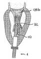
도 2는 도 1의 장치의 구성요소인 이중 루멘(double lumen)을 갖는 인트로듀서 카테터(introducer catheter)의 일 예, 및 인트로듀서 카테터의 주 루멘(principal lumen)에 위치될 수 있으며 도 1의 장치의 제 1 단계를 형성하는 가이드 카테터들의 한 쌍의 일 예를 도시한다.
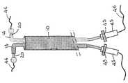
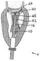
도 3은 도 2의 제 1 단계의 가이드 카테터들에 커플링되는, 장치의 제 2 단계를 형성하는 제어된 편향 기구들이 제공되는, 한 쌍의 카테터들의 일 예를 도시한다.
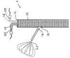
도 4는 장치의 가이드 와이어들을 도시한다.
도 5는 장치의 측방향 단계를 형성하기 위해서 인트로듀서 카테터의 제 2 루멘에 위치 설정되는 가이드 카테터의 일 예, 및 장치의 측방향 단계를 형성하는 가이드 카테터 내로 삽입되는 가이드 와이어 캡처 시스템의 일 예를 도시한다.
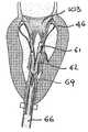
도 6은 도 1의 장치의 전체적인 개략도를 도시하며, 이 구성에서, 인트로듀서 카테터의 제 1 루멘을 통해 심실(ventricular chamber)에 위치 설정되는 가이드 와이어들의 시스템은 인트로듀서 카테터의 제 2 루멘을 통해 전진된 캡처 시스템에 의해 캡처된다.
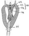
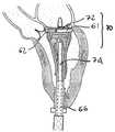
도 7 및 도 8은 도 1의 장치의 전체적인 개략도를 도시하며, 이 구성에서, 가이드 와이어들의 말단 단부들은 캡처 시스템에 의해 심방실 외부측에서 회복된다.
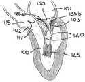
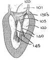
도 9a 내지 도 9c는 인간의 심장, 특히, 좌심실(left ventricular chamber)의 해부학에 주목한 상이한 단면도들을 도시한다.
도 10aa 내지 도 10gb는 도 1의 장치를 사용하여, 자연 승모판(native mitral valve) 둘레의 가이드 와이어들의 시스템을 위치시키기 위한 시술의 일례의 상세들을 도시하며, 도 10aa 내지 도 10ab는 좌심실에서의 인트로듀서 카테터의 위치 설정을 도시하며,
도 10ba 내지 도 10bb는 장치의 제 1 단계를 형성하는 가이드 카테터들의 한 쌍의 위치 설정을 도시하며,
도 10ca 내지 도 10cb는 장치의 제 2 단계를 형성하는 제 1 및 제 2 카테터의 위치 설정을 도시한다.
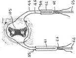
도 10d1 내지 도 10d2는 캡처 시스템의 위치 설정을 도시하며, 캡처 장치는 대동판막륜(annulus of the aortic valve)의 평면 바로 아래로 팽창된다.
도 10ea 내지 도 10eb는 이들의 말단 단부들이 캡처 장치의 메쉬(mesh)를 통해 통과할 때까지 제 2 단계를 통해 좌심실 내로 도입되며 대동막하 공간(subaortic space) 내로 전진되는 한 쌍의 가이드 와이어들의 승모판 둘레 위치 설정을 도시한다.
도 10fa 내지 도 10fb는 캡처 장치에 의해 캡처되는 한 쌍의 가이드 와이어들의 말단 단부들을 도시하며, 그의 시스(sheath)는 대동막하 공간 내로 전진된다.
도 10ga 내지 도 10gb는 좌심실(left ventricle)로부터 제거되는 전개 장치의 제 1 단계 및 제 2 단계를 형성하는 가이드 카테터들의 시스템을 도시하는 한편, 가이드 와이어들이 승모판 둘레에서 제 위치에 유지된다.
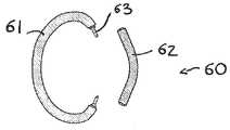
도 11a 내지 도 11b는 방실판막(atrioventricular valve)들을 위한 경피적 판막 인공 삽입물(transcatheter valve prostheses)들을 정착하는 환상 구조의 일례를 도시하며, 이는 도 1의 장치에 위치설정되는 가이드 와이어들의 시스템의 사용으로부터 상당한 이점을 가질 수 있다.
도 12는 위치 설정 및 지지 장치의 일례 상에 미리 장착된 환상 구조를 도시한다.
도 13a 내지 도 13b는 도 11a의 환상 구조의 도입 및 위치 설정을 안내하기 위해서, 도 1에 따른 장치를 사용하여 이전에 위치 설정된 한 쌍의 가이드 와이어들의 사용의 일례를 도시한다. 환상 구조 및 지지 구조의 구성요소들은 초기에 접혀진 구조(collapsed configuration)로 그리고 다음에 펼쳐진 구조(released configuration)로 도시된다.
도 14aa 내지 도 14db는 승모판 대체를 위한 인공 보철(prosthetic) 시스템의 경피적 치환술(transcatheter implantation)을 위한 수술의 일례의 상세들을 도시하며, 이 시스템은 도 11a의 환상 구조 및 접힘 가능한 판막 인공 보철물에 의해 형성되고, 치환술을 위한 가이드로서 도 1의 장치에 의해 이전에 위치설정된 가이드 와이어들을 사용한다.
도 14aa 내지 도 14ab는 좌심실 내로의 환상 구조의 도입 단계를 도시한다.
도 14ba 내지 도 14bb는 환상 구조의 조립 후에 접힘 가능한 판막 인공 보철물을 위치 설정하는 단계를 도시한다.
도 14ca 및 도 14cb는 접힘 가능한 판막 인공 보철물을 펼치는 단계를 도시한다.
도 14da 내지 도 14db는 치환술 수술에 부수적인 장치들의 제거 후에 승모판 상의 인공 보철 시스템을 이식하는 수술의 결과를 도시한다.BRIEF DESCRIPTION OF THE DRAWINGS Figure 1 shows an overall schematic view of an apparatus (also referred to hereinafter as "apparatus") for developing guide structures for surgical procedures in cardiac chambers according to an embodiment of the present invention.
Figure 2 is an example of an introducer catheter with a double lumen that is a component of the device of Figure 1 and a primary lumen of the introducer catheter, Lt; RTI ID = 0.0 > of guide catheters < / RTI >
FIG. 3 shows an example of a pair of catheters, which are coupled to the guide catheters of the first stage of FIG. 2, wherein controlled biasing mechanisms are provided to form the second stage of the device.
Figure 4 shows the guide wires of the device.
Figure 5 is an example of a guide catheter positioned in a second lumen of an introducer catheter to form a lateral step of the device and an example of a guide wire capture system inserted into a guide catheter forming a lateral step of the device / RTI >
Figure 6 shows an overall schematic view of the device of Figure 1 in which a system of guide wires positioned in a ventricular chamber through a first lumen of an introductory catheter is connected through a second lumen of the introducer catheter And captured by an advanced capture system.
Figures 7 and 8 show an overall schematic view of the device of Figure 1, in which the distal ends of the guide wires are restored on the outside of the atrial chamber by the capture system.
Figures 9a-9c illustrate different cross-sections of the heart of a human being, notably focusing on the anatomy of the left ventricular chamber.
Figs. 10aa-gb illustrate details of an example of a procedure for positioning a system of guide wires around a native mitral valve using the apparatus of Fig. 1, Figs. 10aa-10ab showing intro Showing the positioning of the ducer catheter,
Figures 10ba-10bb illustrate the positioning of a pair of guide catheters forming the first stage of the device,
Figures 10ca-c show the positioning of the first and second catheters forming the second stage of the device.
Figures 10d1 to 10d2 show the positioning of the capture system, which expands directly below the plane of the annulus of the aortic valve.
Figures 10ea to 10eb show a pair of guide wires that are introduced into the left ventricle through a second step until their distal ends pass through the mesh of the capture device and are advanced into the subaortic space. Fig.
Figures 10fa-f show the distal ends of a pair of guide wires captured by the capture device, the sheath of which is advanced into the sub-alcanto space.
Figs. 10ga-10gb show the system of guide catheters forming the first and second steps of a deployment device that is removed from the left ventricle, while guide wires are held in place around the mitral valve.
Figures 11a-11b illustrate an example of an annular structure that fixes transcatheter valve prostheses for atrioventricular valves, which may be used from the use of the system of guide wires positioned in the device of Figure 1 Can have significant advantages.
Figure 12 shows an annular structure pre-mounted on an example of a positioning and supporting device.
Figs. 13A-13B illustrate an example of the use of a pair of guide wires previously positioned using the apparatus according to Fig. 1 to guide the introduction and positioning of the annular structure of Fig. 11A. The components of the annular structure and support structure are initially shown in a collapsed configuration and then in a released configuration.
Figures 14aa-ddb illustrate details of an example of a procedure for transcatheter implantation of a prosthetic system for mitral valve replacement, which system is shown in Figure 11a by an annular structure and a collapsible valve prosthesis And uses guide wires previously positioned by the apparatus of Figure 1 as a guide for replacement.
Figures 14a-14ab illustrate the introduction of an annular structure into the left ventricle.
Figures 14ba to 14bb illustrate the step of positioning a foldable valve prosthesis after assembly of the annular structure.
Figures 14ca and 14c show the steps of unfolding a foldable valve prosthesis.
Figures 14d-14db illustrate the results of an operation to transplant an artificial prosthesis system on the mitral valve after removal of devices associated with replacement surgery.
도 1을 참조하면, 이는 본 발명의 일 실시예에 따른 심방실들 내에서의 수술 시술들을 위한 가이드 구조들을 전개하는 장치(1)의 전체적인 개략도를 도시한다. 이 장치는, 심방실 내로의 비침습적 방식(non-invasive manner)으로 도입되며 시술자(operator)에 의해 제어되는 소망하는 경로들을 따라 그 내부를 통과하는(navigating) 주목적을 갖는 다양한 구성요소들로 구성된다. 이 장치는, 박동 심장(beating heart)에 이용가능하도록 그리고 이에 따라 체외 혈액 순환(extracorporeal blood circulation)을 위한 어떠한 필요도 없이, 자연 심장 판막들의 작동에 대한 심각한 간섭 없이 창작되었으며, 이에 따라 전체적으로 비외상성(atraumatic) 그리고 양면성(reversible) 시술을 하게 한다. 진행중인 시술은, 언제라도 중단될 수 있으며, 장치의 구성요소들은 심장의 기능 자체에 어떠한 영향들 없이 심방실로부터 제거될 수 있다. 마지막으로, 장치는, 반경 방향으로 작은 전체 치수 및 매끄러운 프로파일, 불연속성들이 없으며, 경피적 시술들에 의해 심장 공동들(cardiac cavities) 내로 도입하기에 특히 적합하다.
Referring to FIG. 1, there is shown a general schematic view of an
장치(1)는 본질적으로 멀티 루멘 가이드에 의해 형성된 중심 본체(10)(이른바, 인트로듀서), 즉, 그 내부에 제공된 다양한 별개의 통로들(12, 18)(또한, 루멘들로서 공지됨)이 제공된 것으로 구성되며, 심장 내에서 작동하도록 의도된 개별 기기장치들을 위한 심방실들에 대한 접근 채널들을 형성하는 주목적을 갖는다. 이러한 기구들은 이들이 특정 목적들을 위해 의도되기 때문에 다양한 유형들일 수 있다. 예컨대, 이러한 기구들은 영구적이며 조절 불가능한 방식으로 미리 형성된 이들의 단자 부분(terminal part)들을 갖는 카테터들을 안내할 수 있다. 이러한 유형의 가이드 카테터들은 단순히 미리 정해진 각도로 구부러진(bent) 이들의 단자 부품들을 가질 수 있어, 이들 내부측으로 전진되는 장치들을 이러한 각도로 편향시킨다. 대안으로, 이러한 카테터들은 특정한 해부학적 상황들에 이들을 특히 적합하게 하는 훨씬 복잡한 곡선들 또는 프로파일들로 미리 형성된 이들의 말단 부품들을 가질 수 있다.
The
도 1에 개략적으로 도시된 장치에 사용될 수 있는 다른 유형의 카테터는, 시술자의 요구사항들에 따라 시술중 조절 가능한 편향 시스템이 끼움 장착되는 카테터들 또는 가이드 카테터들을 포함할 수 있다. 스티어링 기구로서 종래에 공지된 이러한 유형의 기구에 의해, 카테터는 시술의 요건들에 따라 시술자에 의해 판정되는 양만큼 편향 및/또는 구부러질 수 있다. 이러한 자유도는 카테터가 보다 양호하게 구성되게 하며, 그의 구성이 예측하기 어려운 해부학적 구조들 내에서 그의 내비게이션으로 더욱 제어가능할 수 있다. 직접적이며 효과적인 방식(이력 현상의 효과들 또는 탄성효과들 없이)으로 카테터를 회전시킬 수 있는 가능성, 또는 상이한 평면들 상에 다수의 편향 시스템들을 제공하는 가능성으로 인해서, 이러한 유형의 카테터의 조종 가능성(steerability)은 거의 완전해서, 3차원 공간들에서 제어된 방식으로 내비게이팅되는 것을 가능케 한다.
Other types of catheters that may be used in the device shown schematically in Figure 1 may include catheters or guide catheters that are fitted with an adjustable deflection system during the procedure, depending on the requirements of the practitioner. With this type of device known in the art as a steering mechanism, the catheter can be deflected and / or bent by an amount determined by the practitioner in accordance with the requirements of the procedure. This degree of freedom allows the catheter to be better structured, and its configuration may be more controllable with its navigation within the anatomical structures that are difficult to predict. Due to the possibility of rotating the catheter in a direct and effective manner (without the effects of hysteresis effects or elastic effects), or the possibility of providing multiple deflection systems on different planes, the maneuverability of this type of catheter steerability is almost complete, allowing it to navigate in a controlled manner in three-dimensional spaces.
일반적으로 내부 루멘을 갖기 때문에, 임의의 가이드 카테터는 가이드 와이어를 위치 설정하거나 앞선 단계의 루멘의 직경에 필적하는 외경을 갖는 다른 카테터를 위치 설정하는데 명확하게 사용될 수 있다.
Because it generally has an internal lumen, any guide catheter can be clearly used to position a guide wire or to position another catheter having an outer diameter comparable to the diameter of the lumen of the previous step.
도 1에 개략적으로 도시된 장치의 적용에 사용될 수 있는 다른 도구들은, 본 발명의 일반적인 특성을 제한하지 않고, 스네어링 장치(snaring device)들로서 종래 기술에 공지된 내강내(endoluminal) 포획 장치들을 포함한다. 통상적으로 금속 또는 중합체 재료들로 만들어진 접힘 가능한 루프식 구조들로 구성된 이러한 장치들은, 가이드 와이어들의 자유 단부들 또는 작은 게이지의 카테터들을 포착하는데 특히 적합하다. 이는, 이 장치들이 캡처 볼륨을 생성하기 위해서 공간적으로 팽창하는 구조들을 갖기 때문이다. 캡처 볼륨을 통해 통과하는 카테터들 또는 가이드 와이어들 또는 유사한 장치들의 자유 단부들은 통상적으로 팽창 시술의 반대인 시술에 의해서 다시 접혀질 때 구조에 의해 트랩된다. 이렇게 하여, 카테터 또는 가이드 와이어의 말단 단부가 부여된 위치에 고정될 수 있거나, 또는 캡처 시스템을 삽입하기 위해 사용되는 것과 동일한 경로를 따라 심방실의 외부측으로 회복될 수 있다.
Other tools that may be used in the application of the device shown schematically in Figure 1 include endoluminal capture devices known in the art as snaring devices without limiting the general nature of the present invention do. Such devices, which are typically constructed of foldable loop structures made of metal or polymeric materials, are particularly suited for capturing free ends of guide wires or small gauge catheters. This is because these devices have structures that spatially expand to create a capture volume. The free ends of catheters or guide wires or similar devices passing through the capture volume are trapped by the structure when folded back by the procedure, which is typically the opposite of the dilation procedure. In this way, the distal end of the catheter or guide wire can be secured in the given position, or can be restored to the outside of the atrial chamber along the same path as used to insert the capture system.
다른 유형들 그리고 다른 기능들을 갖는 내강내 수술 도구들은 여기서 설명된 본 발명의 사상에 편리하게 사용될 수 있어, 심방실들에서의 수술 시술들을 위한 가이드 구조들을 전개한다.
Intraluminal surgical instruments having different types and other functions can be conveniently used in the context of the present invention described herein to develop guide structures for surgical procedures in atrial chambers.
도 1은 특히, 심장의 심첨부(apical region)에 근접한 심실(ventricle)의 벽을 통한 접근에 의해 심실에서 사용하기에 특히 적합한 본 발명의 특정 실시예를 도시한다. 후속 도면들(도 2 내지 도 6)에서 더욱 완벽하게 그리고 더욱더 상세하게 도시된 바와 같이, 전체 장치는 이중 루멘 인트로듀서 부재(10), 고정된 곡률(fixed curvature)로 그의 말단 단부들에 미리 형성되고 인트로듀서의 주 루멘(12) 내에서 이들에 진행(advance)과 양립가능한 치수들을 갖는 한 쌍의 가이드 카테터(14)들, 실질적으로 직선식(rectilinear)이지만 가요적이며, 인트로듀서의 측방향 루멘(18) 내에서 이의 진행과 양립가능한 치수들을 갖는 가이드 카테터(16), 실질적으로 직선식이지만 조절 가능한 편향 기구에 의해 이들의 말단 구역들에 끼워 맞춤되며 가이드 카테터들의 제 1 세트 내에서 이들의 진행과 양립가능한 전체적인 반경 방향 치수들을 갖는 한 쌍의 카테터(20)들, 및 측방향 가이드 카테터 내에서 그의 진행과 양립가능한 반경 방향 치수들을 갖는 캡처 장치(22)로 구성된다.
Figure 1 shows a particular embodiment of the invention particularly suitable for use in the ventricle by access through a wall of the ventricle proximate to the apical region of the heart. As shown more fully and in more detail in the following Figures (Figures 2 to 6), the entire apparatus comprises a dual
이 장치의 목적은, 예컨대, 시술자에 의해 판정되며 심방실에서 가이드 카테터들의 제 2 세트의 내비게이션에 의해 형성되는 경로들을 후속하는, 가이드 카테터들의 제 2 세트를 통해 심실 내에 도입되고 진행되는 가이드 와이어들을 위치 설정하는 것일 수 있다. 이러한 가이드 와이어들의 말단 단부들은, 캡처 장치를 사용함으로써 포획될 수 있어, 심실 내에서 고정된 위치에 이들을 유지하거나 심장의 외부측으로 이들을 잡아당기고 시술자에 의해 이들이 접근가능하게 한다.
The purpose of this device is to guide the guide wires introduced and advanced into the ventricle through the second set of guide catheters, for example, following the routes determined by the practitioner and formed by the navigation of the second set of guide catheters in the atrial chambers It can be a location setting. The distal ends of these guide wires can be captured by using a capture device to hold them in a fixed position in the chamber or to pull them outwardly of the heart and make them accessible by the practitioner.
금속 재료들 및/또는 방사선 불투과성(radiopaque) 마커들의 사용은, 장치의 구성요소들을 X-선들로 볼 수 있게 하며, 이에 따라 심장내 수술(intracardiac procedure)들이 형광투시적 시각화(fluoroscopic visualization)에 의해서 안내될 수 있음에 주목해야 한다. 일부 경우들에서, 에코 심박동 기록기의(echocardiographic) 서포트가 또한 유용할 수 있다. 도 1에 도시된 장치의 특정 실시예를 참조하여, 도 2는 인트로듀서 카테터의 구축을 위한 가능한 해법을 도시한다. 단면도는 본 발명의 이러한 특정 실시예에서의 이러한 구성요소의 이중 루멘 특징을 도시한다. 주 루멘으로서 단순화를 위해 식별되는 제 1 루멘(12)은, 카테터의 선단 단부 및 말단 단부(26)에서 각각 위치 설정되는 인트로듀서 카테터의 주축, 선단 오리피스 및 말단 오리피스(24)에 평행하게 이어진다. 보조 루멘으로서 단순화를 위해 식별되는 제 2 루멘(18)은, 인트로듀서 카테터의 선단 단부에 위치 설정된 선단 오리피스를 갖는 직선형 선단 부분(28)을 특징으로 한다. 그러나, 카테터의 중간 구역(30)의 근처에서, 보조 루멘(18)은 외부측을 향해서 편향된다. 따라서, 보조 루멘의 말단 오리피스(32)는 인트로듀서 카테터의 측방향 표면(34) 상에 위치된다. 이에 따라, 주 루멘의 진행 축은, 보조 루멘의 곡률에 의해 판정되는 각도로 제 2 루멘의 진행 축으로부터 오프셋된다. 이러한 유형의 장치의 의도된 사용에 양립가능한 각도는, 15° 내지 45° 범위 내에 있을 수 있다.
The use of metallic materials and / or radiopaque markers allows the components of the device to be viewed as X-rays, thereby allowing intracardiac procedures to be applied to fluoroscopic visualization As shown in FIG. In some cases, echocardiographic support of an echo cardiac recorder may also be useful. Referring to a particular embodiment of the device shown in Figure 1, Figure 2 shows a possible solution for the construction of an introductory catheter. The cross-sectional views illustrate the dual lumen features of such components in this particular embodiment of the present invention. The
이에 따라, 상기 설명된 구조적 해법은, 심방실의 2 개의 상이한 영역들에 대한 억세스 루트(access route)를 만든다. 인트로듀서 카테터의 중간 높이(intermediate level)에 외측방 만곡을 또한 특징으로 하는 추가의 루멘들의 추가 가능성은 심방실의 상이한 영역들에 대한 억세스 경로들을 만들 것이다.
Thus, the structural solution described above creates an access route for two different areas of the atrial chamber. The additional possibility of additional lumens, which also feature an outward curvature at an intermediate level of the introducer catheter, will create access paths to different areas of the atrial chamber.
여전히, 도 1에 묘사된 특정 실시예를 참조하면, 도 2는 또한 인트로듀서 카테터의 주 루멘(12)을 앞설 수 있는 가이드 카테터(14)들의 세트를 도시한다. 본 발명의 이러한 특정 실시예에서, 이러한 제 1 가이드 카테터 단계는, 실질적으로 직선형 선단 부분(36) 및 선단 부분(36)에 대해서 약 90°로 미리 구부러진 말단 단부(38)를 갖는, 미리 형성된 유형이다. 보다 일반적으로는, 이러한 카테터 단계의 목적은, 인트로듀서의 축에 평행한 방향으로부터 가이드 카테터의 말단 단부의 만곡도(degree of curvature)에 의해 판정되는 앞선 것보다 각진 방향으로 카테터 내에서 진행되는 장치들의 축을 편향시키는 것이다. 적용에 따라, 이러한 각도는 카테터의 선단 부분의 축에 대해서 45° 내지 135°로 변할 수 있으며, 이는 인트로듀서의 축에 실질적으로 평행하다. 이에 따라, 심방실 내의 카테터 또는 가이드 와이어와 같은 장치의 전진축은 심장 내로의 이의 도입을 위해 요구되는 축에 관계 없어진다.
Still referring to the particular embodiment depicted in FIG. 1, FIG. 2 also shows a set of
가이드 카테터들은 축방향 회전에 자유로우며, 이에 따라 말단 만곡부는 상이한 방향들로 배향될 수 있다. 도 2에 도시된 특정 실시예에서, 예컨대, 제 1 단계의 2 개의 가이드 카테터(14)들의 말단 단부(38)들은 반대 방향들을 따라 배향될 수 있다. 따라서, 2 개의 가이드 카테터들의 루멘에서 전진되는 장치들은, 반대 방향들에서 연장하는 경로들을 따르는 것을 제외하고는, 인트로듀서 카테터의 축에 수직한 동일 평면으로 편향된다. 명확하게는, 이것이 카테터들의 반경 방향 전체 치수들과 양립가능하다면, 제 1 단계를 형성하는 다수의 카테터들을 갖는 것이 또한 가능할 것이다.
The guide catheters are free to rotate in the axial direction so that the distal curvature can be oriented in different directions. In the particular embodiment shown in Figure 2, for example, the distal ends 38 of the two
제 1 단계를 형성하는 가이드 카테터(14)들은 중합체 또는 금속 재료로부터 또는 이들의 조합으로부터 만들어질 수 있다. 재료는 대향 요건들에 들어맞도록 선택되어야 한다. 이는, 왜냐하면 가이드 카테터가 심방실 내로 나타날 때 그의 미리 형성된 구성을 회복하는, 인트로듀서의 주 루멘(12) 내에서 전진하도록 될 때 단자 부품(38)이 적어도 부분적으로 직선화될 수 있어야 하기 때문이다. 다른 한편으로, 미리 형성된 부품은 가이드 카테터의 루멘 내로 삽입되는 장치를 편향시키기에 충분히 강성이 있어야 한다. 또한, 제 1 단계를 형성하는 가이드 카테터가 비틀림 강성(torsional rigidity)의 특징들을 갖는 것, 즉, 선단 섹션으로부터 말단 섹션으로 토크를 전달할 수 있는 것이 바람직하다.
The
여전히, 도 1에 도시된 특정 실시예를 참조하면, 도 3은 또한 제 2 가이드 카테터 단계를 형성하는 카테터(20)들의 일 세트를 도시하며, 전체적인 반경 방향 치수들은 카테터들이 도 2에 묘사된 바와 같이 제 1 단계를 형성하는 가이드 카테터(14)들의 루멘들 내에서 이들의 전진과 양립가능하게 하는 것을 특징으로 한다. 본 발명의 이러한 특정 실시예에서, 이 제 2 단계에 속하는 카테터는 전진되는 가이드 카테터의 말단 만곡부를 통해 통과하도록 실질적으로 직선형이며 측방향으로 가요성이며, 카테터의 선단 단부에서 핸들(45) 상에 위치 설정되는 제어부(43)들에 의해서 구동되는 하나 또는 그 초과의 편향 기구(42)(스티어링 기구들로서 공지됨)가 그의 말단 부분(40)에 제공된다. 제어부를 작동시킴으로써, 가이드 카테터의 말단 부분의 점진적이며 제어된 편향이 성취될 수 있어, 가장 복잡한 해부학적 조건들에서조차, 카테터가 시술자에 의해 판정되는 경로들을 따라 내비게이팅할 수 있게 된다. 바람직하게는, 가이드 카테터는 실질적으로 직선형이며, 실질적으로 강성의 선단 부분이 말단 부분에 토크를 전달할 수 있다. 카테터의 전체 길이를 따라 적어도 절반을 연장하는 말단 부분은, 편향되기에 충분히 가요적인 반면, 또한 말단 부분에 유사한 경로로 비틀림에 대해 강성이다. 제 1 단계의 가이드 카테터(14)에 의해 만들어진 만곡부가 존재할 때조차, 전체 가이드 카테터가 임의의 상당한 탄성 지연 또는 이력현상 없이 핸들(45)을 회전시킴으로써 단순히 단일 유닛으로서 회전될 수 있기 때문에, 제 2 단계의 내비게이션 능력은 상당히 증가된다. 사실상, 제 2 단계를 형성하는 가이드 카테터(20)들 각각은, 시스템의 제 1 단계를 형성하는 가이드 카테터(14)들 내에서 슬라이드 및 회전하는데 자유롭다.
Still referring to the particular embodiment shown in FIG. 1, FIG. 3 also shows a set of
카테터의 최적의 기계적 특성들, 즉 비틀림 강성과 조합된 높은 측방향 강성은 카테터를 위한 정확한 구조적 해법들을 사용함으로써 성취될 수 있다. 예컨대, 카테터 벽을 형성하도록 중합체 기재에 매립된 와이어 메쉬의 적절한 금속 보강의 사용은 높은 비틀림 강성을 제공하는 구조적 해법인 동시에, 그의 굽힘 변형성(bending deformability)을 보존하고 굽힘시 임의의 접힘 우려(꼬임(kinking)으로서 공지됨)를 회피한다.
The optimal mechanical properties of the catheter, i.e. high lateral stiffness combined with torsional stiffness, can be achieved by using accurate structural solutions for the catheter. For example, the use of appropriate metal reinforcement of a wire mesh embedded in a polymeric substrate to form a catheter wall is a structural solution that provides high torsional stiffness, while at the same time preserving its bending deformability, (known as kinking).
제 2 단계를 형성하는 가이드 카테터의 말단 단부 및 제 1 단계를 형성하는 가이드 카테터의 말단 단부에는, 이들에 대한 카테터의 우연한 충격 또는 마찰의 경우에조차, 올리브(olive) 형상으로 만들어지거나 심방실의 또는 심방실에 존재하는 다른 해부학적 구조들의 벽들에 대한 임의의 가능한 손상을 방지하도록 구성된 연질의 변형가능한 재료로 만들어진 비외상성 팁(44)이 제공될 수 있다.
The distal end of the guide catheter forming the second step and the distal end of the guide catheter forming the first step are made in an olive shape or even in the event of accidental impact or friction of the catheter thereto, Or
도 4는 제 2 단계를 형성하는 카테터(20)들이 중재 시술들 (interventional procedures)을 위한 장치들, 이를테면 카테터의 선단 개구에 삽입되고 카테터(20)의 말단 단부로부터 나타남으로써 심방실에 도달할 때까지 그의 내부 루멘을 따라 전지하도록 만들어질 수 있는 더 작은 게이지 카테터들 또는 가이드 와이어들(46)(도면에 도시된 바와 같음)을 위한 장치들의 통과(passage)를 허용하는 내부 루멘들을 어떻게 갖는지를 도시한다. 가이드 와이어(46)들은 가이드 카테터의 선단 오리피스 내로 삽입되며, 제 1 및 제 2 단계들의 가이드 카테터(14, 20)들의 시스템에 의해 접근가능해진 경로를 따라 이 지점에서 심방실 내에서 말단 오리피스로부터 나타날 때까지 내부에서 전진하게 된다.
FIG. 4 shows that when the
여전히 도 1의 특정 실시예를 참조하면, 도 5는 중재 시술들을 위한 장치들, 예컨대 도면에 도시된 바와 같이, 인트로듀서의 축으로부터 오프셋 방향으로 추가의 가이드 카테터(16)(또한, 측방향 단계라 부름)를 전진시키기 위해서 인트로듀서 카테터(10)의 보조 루멘(18)을 사용하는 가능성을 도시한다. 도 2 및 도 3에 묘사된 유형의 가이드 카테터들은, 또한 보조 루멘(18)을 통해 사용될 수 있다. 이러한 측방향 가이드 카테터는 가이드 카테터들의 주 시스템의 방향과 상이한 방향으로 심방실로 추가의 접근 경로를 만든다. 도 5는 본 발명의 특정 실시예에서, 내강내 캡처 장치(22)(스네어링 장치(snaring device))가 인트로듀서 카테터의 보조 루멘 내로 삽입되는 가이드 카테터(16)를 통해 심방실 내로 어떻게 도입될 수 있는지를 도시한다. 도면에 도시된 본 발명의 특정 실시예에서, 캡처 장치(22)는 높은 탄성 특성들을 갖는 금속 와이어의 루프(48)들의 세트로서 나타내며, 그의 원점(point of origin)들은 또한 금속인 스템(50)의 말단 단부에서 함께 결합된다. 스템(50)은 얇고 가요적이며, 심실로의 그의 접근에 후속될 경로의 곡률에 적응될 수 있다. 스템의 선단 단부는 시술자가 접근가능하여, 캡처 장치의 위치 설정이 제어될 수 있다. 도면 상에 도시된 루프 구조는, 얇은 벽의 작은 게이지 시스(52)(또한 도 5에 도시됨) 내로 용이하게 접혀질 수 있으며, 그의 제거시, 말단 구조는 그의 팽창된 구성으로 즉각적으로 복귀한다. 즉, 캡처 장치에 대한 시스의 위치 설정은, 캡처 장치의 구성을 판정하며, 이는 시스가 장치를 커버한다면 접혀지고 또는 시스가 스템의 위치에서 후퇴된다면 팽창된다.
Still referring to the particular embodiment of FIG. 1, FIG. 5 illustrates an apparatus for an interventional procedure, such as an additional guide catheter 16 (also shown in the lateral direction Lt; RTI ID = 0.0 > 18 < / RTI > The guide catheters of the type depicted in Figures 2 and 3 may also be used through the
다중 루프(48)들 그리고 이들의 꽃모양(flower-like) 구성 때문에, 이러한 장치는 다방향 캡처를 가능케 하여, 캡처될 장치에 대한 그의 배향이 덜 중대해진다. 와이어는 단지 장치가 다시 접혀질 때 캡처되도록 팽창된 장치의 루프들 중 하나를 통해 임의의 방향으로 통과될 필요가 있다. 명확하게는, 캡처 장치의 구조를 위한 가능한 매우 다양한 설계들이 존재하며, 이러한 설계들은 제공될 특별한 기능에 따라 또는 충족될 임의의 특별한 요건들에 따라 또한 변할 수 있다. 이러한 설계들의 대부분은 종래 기술에 공지되어 있다.
Because of the
캡처 장치용으로 높은 기계적 성능을 갖는 재료, 예컨대 니티놀(nitinol)과 같은 초탄성 금속 합금들을 사용함으로써 그리고 시스를 위한 폴리아미드 또는 금속 메쉬가 보강된 폴리아미드와 같은 테크노폴리머(technopolymer)들을 사용함으로써, 내강내 용도로 양립가능하게 하는 캡처 시스템(시스 및 캡처 장치를 포함함)의 전체 반경 방향 치수들을 제한할 수 있으며; 특히, 예시된 예에서, 직경은 측방향 단계의 직경보다 더 작아야 한다. 보다 일반적으로는, 일반적인 내강내 캡처 적용들을 위해 현재 사용하는 시스템들의 전체 반경 방향 치수들은 1 내지 3 mm 범위 내에 있지만, 1 mm 미만의 치수들이 또한 가능하다.
By using materials with high mechanical properties for the capture device, for example, by using superelastic metal alloys such as nitinol and by using technopolymers such as polyamide or metal mesh reinforced polyamide for the sheath, Limit the overall radial dimensions of the capture system (including the sheath and capture device) that make it compatible for use in the lumen; In particular, in the illustrated example, the diameter should be smaller than the diameter of the lateral steps. More generally, the overall radial dimensions of currently used systems for general intraluminal capture applications are in the range of 1 to 3 mm, but dimensions of less than 1 mm are also possible.
도 2 내지 도 5에 묘사된 특정 해법들의 관점에서, 도 6은 그의 작동 구성에서 본 발명의 일 실시예에 따른 심방실들 내에서의 중재 시술들을 위한 가이드 구조들을 전개하는 장치의 전체적인 개략적 표면을 도시한다. 심방실로의 접근 포트를 제공하기 위해서 심장의 외벽을 통해 위치 설정되는 인트로듀서 카테터(10)의 주 루멘(12)을 사용함으로써, 시술자는 적용에 의해 요구되는 경로들을 후속하는, 그의 요구사항들에 따라 제 1 및 제 2 단계들의 가이드 카테터(14, 20)들을 위치 설정할 수 있다. 제 2 단계의 카테터(20)들의 경우에, 카테터의 말단 단부의 이동시에 허용가능한 다양한 자유도들(축방향 전진, 그 자체 축을 중심으로 한 회전, 조절가능한 편향 기구)이 소망하는 경로들이 후속될 수 있고 최종 위치들이 특히 바람직하지 않은 해부학들의 존재에서조차 도달될 수 있도록 된다. 시술자는, 제어 스템(control stem)(50)에 의해 시스템의 단부 위치를 결정하고, 대응하여 포함하는 시스(52)에 작용함으로써 그의 구조를 변화시키는(팽창되거나 접혀짐), 인트로듀서 카테터(10)의 보조 루멘(18)에 위치 설정된 가이드 카테터(16)를 통해 심방실 내로 캡처 시스템(22)을 도입할 수 있다. 보조 루멘(18)의 특정한 기하학적 형상으로 인해, 캡처 장치(22)의 축이 그의 작용을 더 단순하고 보다 효과적으로 만드는 주 루멘(12)의 카테터들에 대해 오프셋된다. 이는, 가이드 와이어들의 말단 단부(47)들이 캡처 장치(22)에 의해 파지될 수 있도록 심방실 내로 가이드 와이어들이 나타날 때까지 시술자가 보조 단계를 형성하는 카테터들의 루멘들 내에서 가이드 와이어(46)들을 전진할 수 있기 때문이다. 이 캡처 장치는, 예컨대 가이드 와이어들의 말단 단부들을 안정화시키기 위해서, 후속 심장내 수술(intracardiac operation)들의 지지에 사용될 수 있다.
In view of the particular solutions depicted in FIGS. 2-5, FIG. 6 illustrates the overall schematic surface of an apparatus for deploying guide structures for interventional procedures in atrial chambers in accordance with an embodiment of the present invention in its operational configuration Respectively. By using the
도 7 및 도 8은 상기 설명된 것과 상이한 캡처 장치의 사용을 도시한다. 이 예에서, 캡처 장치(22)는 가이드 와이어들의 말단 단부들을 선단 위치로 회복하도록 사용된다. 이는, 이러한 시술을 목적으로 사용되는 가이드 와이어 또는 와이어들의 양 단부들에서 시술의 종료시에 접근하는 시술자에 의해 판정되는 경로를 따라 심장 공동들 내에서 하나 또는 그 초과의 가이드 와이어들을 위치 설정하는 것을 가능케 한다.
Figures 7 and 8 illustrate the use of capture devices different from those described above. In this example, the
제 1 단계에서, 시술자는 소망하는 경로(그의 길이의 전체 또는 부분에 걸침)를 후속함으로써 가이드 카테터(14, 20)들의 시스템을 전진 및 위치 설정한다. 이후, 가이드 와이어(46)(또는 가이드 와이어들)는 이러한 카테터의 말단 오리피스로부터 나타나는 것을 유발하는 제 2 단계 가이드 카테터(20)의 내부 루멘을 통해 심장 공동 내로 도입된다. 가이드 와이어는 캡처 장치(22)에 의해 캡처되는 것을 허용하도록 심장 공동 내에서 충분히 전진된다. 심장 공동으로부터 캡처 시스템을 제거함으로써, 조작자는 또한 가이드 와이어(또는 가이드 와이어들)의 말단 단부(47)를 회복한다. 이에 따라, 하나 또는 그 초과의 가이드 와이어(46)들이 시술자에 의해 특정된 경로들을 따라 심장 공동 내에 위치설정될 수 있다. 시술의 종료시, 시술자는 심방실 내에 위치 설정되는 가이드 와이어들의 말단 단부(47)들 및 선단 단부들로 동시 접근한다. 도 7은 가이드 와이어(46)들의 말단 단부(47)들이 캡처되고 캡처 시스템(22)이 꺼내진(drawn out) 후에: 가이드 와이어들은 인트로듀서(10)의 주 루멘(12) 내로 삽입되는 카테터(14, 20)들의 시스템을 통해 심장 공동에 진입하고 보조 루멘(18)에 삽입된 가이드 카테터(16)를 통해 나가는 장치의 구성을 도시한다. 마지막으로, 도 8은 이에 따라 후속한 중재 시술의 가이드 구조들로서 사용될 수 있는 가이드 와이어(46)들만이 원 위치로(in situ) 나가는 가이드 카테터들의 전체 시스템의 제거를 도시한다.
In the first step, the practitioner advances and positions the system of
도 1에 도시된 바와 같은 심방실들 내에서 중재 시술들을 위한 가이드 구조들의 전개를 위한 장치(1)의 좌심실에 관한 예시적 적용의 상세 설명을 제공하기 위해서, 도 9a 내지 도 9c에 도시된 심장을 따라 취한 해부학적 섹션들의 다이어그램들이 사용될 것이다. 특히, 도 9a 및 도 9b는 심장의 좌측의 길이방향 축을 따라 취한 2 개의 도면들, 즉, 좌측의 2 개의 챔버들의 길이방향 축들을 따라, 끄트머리(apex)(즉, 심장의 하부 지점)로부터 심장의 상부로, 실질적으로 심장을 절개한 섹션들의 도면들을 도시한다. 따라서, 이러한 섹션들은 좌심실(100)(끄트머리를 포함하여 하부 챔버) 및 좌심방(101)(상부 챔버) 양자 모두를 도시한다. 도 9a는 좌심실의 명목상 축(nominal axis) 및 대동판막(aortic valve)(102)의 축에 의해 식별되는 평면을 따라 심장의 좌측을 따라 섹션을 취함으로써 얻어진 도면을 도시한다. 이 경우에, 섹션 평면(section plane)은 후판막첨(posterior leaflet) 및 전판막첨(anterior leaflet)의 중간 라인을 따르며 뿐만 아니라 대동판막을 따라 취한 섹션을 취하는 그의 전후 축(anteroposterior axis)을 따라 승모판(mitral valve)(103)을 절개한다. 따라서, 이 섹션은 대동맥 근위부(115)가 대동판막 구조(102) 및 대동 판막하부 챔버(aortic subvalvular chamber)(117)와 함께 시각화되는 것을 가능하게 하며, 통상적으로 좌심실 유출로(LVOT; left ventricle outflow tract)라 한다. 승모판의 양쪽 판막첨들, 즉 전판막첨(135a) 및 후판막첨(135b)은 또한 섹션에서 볼 수 있다. 승모판은 좌심실(100)로부터 좌심방(101)을 분리한다. 승모판륜(mitral annulus)(120), 힘줄끈(chordae tendineae)(140) 및 꼭지근(papillary muscle)(145)은 서로 분명히 동일한 해부학적 구조들이다. 꼭지근들( 및 대응하는 힘줄끈)의 단일 그룹이 이 도면에서 가시적이다. 도 9b의 경우에, 심장의 좌측 도면은, 섹션 평면이 승모판의 교련-교련 축(commissure-commissure axis)에 정렬될 때까지 심실의 축을 중심으로 회전된다면 나타나는 것으로 도시된다. 이 도면은 힘줄끈(140) 및 꼭지근(145)에 의해 형성된 대응하는 판막하부 구조와 승모판륜(120)의 대응하는 부분을 갖는 승모판의 후판막첨(135b) 만을 도시한다. 이 섹션은 양쪽의 꼭지근들을 (단면으로) 도시한다. 마지막으로, 도 9c는 좌심방이 덮여있지 않다면 나타나는 바와 같은 판막상부 방향으로부터 본 승모판의 평면도를 도시한다. 승모판 전엽(anterior mitral leaflet)(135a) 및 후엽(135b)을 볼 수 있다. 양쪽 판막엽들은 승모판륜(120)에 의해 좌심실의 근육 구조에 둘러싸이고 연결된다. 승모판륜을 따라 2 개의 판막엽들 사이의 천이 구역들은 교련 구역(commissural region)(127)들이다. 이는 승모판의 배향의 2 개의 주된 직교축들, 즉 중간 라인을 따라 양쪽 판막엽들을 통해 통과하는 전후 방향(anteroposterior direction)으로 대칭인 축 및 교련-교련 방향을 따라 정렬된 앞선 축에 직교하는 축을 명확하게 도시한다. 마지막으로, 판막엽들의 자유 모서리(free margin)들을 꼭지근(145)들에 고정하는 힘줄끈(140)의 다발들은 승모판의 오리피스를 통해 볼 수 있다.
In order to provide a detailed description of the exemplary application of the
도 10aa 내지 도 10gb는 경심첨부 접근(transapical access)을 통해 좌심실 내로 시스템을 삽입하고 본 발명의 특정 실시예로서 도 1에 도시된 바와 같이 심방실들 내에 중재 시술들을 위한 가이드 구조들을 전개하기 위한 장치(1)를 사용함으로써, 자연 승모판(103)을 둘러싸도록 가이드 와이어들의 시스템의 전개에 후속되는 가능한 시술의 상세들을 도시한다.
Figures 10aa-10gb illustrate a device for inserting a system into a left ventricle via transapical access and deploying guide structures for interventional procedures in atrial chambers as shown in Figure 1 as a specific embodiment of the present invention. Lt; RTI ID = 0.0 > (1) < / RTI >
도 10aa 및 도 10ab는 심장의 좌측을 통해 취한 2 개의 상이한 섹션들에서의 시술의 초기 단계를 묘사한다. 이러한 시술을 묘사하는 후속 도면들에서 동일한 표시 모드가 사용된다. 도면들은, 승모판의 중간 라인 상에서 승모판(103)의 후판막첨(135b)의 후방에서 경심첨부 접근을 통해서 심실 벽에 인접한 인트로듀서 카테터(10)의 말단 단부의 위치 설정을 도시한다. 이 위치에서, 인트로듀서 카테터(10)는 그의 심실 측 상에 자연 승모판륜(native annulus of the mitral valve)으로의 직접적인 접근을 만든다. 인트로듀서 카테터(10)는, 보조 루멘(32)의 말단 오리피스가 캡처 시스템이 전진되는 방향으로 대동판막(102)을 향해 지향되도록 그의 축 상에서 각지게 배향되어야 한다. 도 10ba 및 도 10bb는, 다시 심장의 좌측의 2 개의 상이한 도면들에서, 제 1 단계를 형성하는 가이드 카테터(14)들의 위치 설정을 도시한다. 이들은, 카테터들이 심실측 상에서 승모판륜의 평면에 근접할 때까지 인트로듀서 카테터(10)의 주 루멘(12)을 따라 전진된다. 이후, 카테터들은 카테터들의 만곡된 말단 단부(38)들이 반대 방향들을 제외하고 승모판륜의 중간 라인에 접선방향으로(tangentially) 양쪽으로 배향된다. 이러한 배향은 후속 단계의 카테터들이 승모판륜에 평행한 방향으로 안내되는 것을 가능케 한다. 이러한 카테터의 말단 에지 상에서, 그리고 시스템의 다른 구성요소들 상의 방사선 불투과성 마커들의 존재로 인해, 시스템의 배향은 X-선을 기반으로 하는 이미지화 시스템들(이를테면, 형광 투시 시스템들)에 의해서 즉시 더욱 가시화될 수 있다.
Figures 10aa and 10ab depict the initial steps of the procedure in two different sections taken through the left side of the heart. The same display mode is used in subsequent figures depicting such procedures. The figures show the positioning of the distal end of the
도 10ca 및 도 10cb는 그중 각각이 승모판 중 하나의 반부(half)를 둘러싸는, 장치의 제 2 단계를 형성하는 카테터(20)들의 위치 설정을 도시한다. 장치의 제 1 단계를 형성하는 카테터(14) 및 인트로듀서 카테터(10)는 승모판의 후판막첨(135b)의 후방에 위치설정되는 한편, 장치의 제 2 단계를 형성하는 카테터(20)들의 말단 단부들은 전판막첨(135a)의 후방에 대면한다. 도면들은, 카테터(20)들의 말단 단부에서 제어된 편향 기구뿐만 아니라 축방향으로 회전되는 그의 성의 존재가 카테터의 말단 단부의 내비게이션의 제어를 개선하는 것을 도시한다. 승모판 해부학의 특정 구역들에서, 예컨대 교련 구역들에서, 이는 카테터의 정확한 위치 설정을 위해서 본질적이다.
Figures 10ca and 10cb illustrate the positioning of the
따라서, 장치의 제 2 단계를 형성하는 카테터들의 말단 단부들 양자 모두는, 승모판의 전판막첨 직후의 대동판막 아래 공간(LVOT라 함)(117)에서 서로 대면한다.
Thus, both of the distal ends of the catheters forming the second stage of the device face each other in a space (referred to as LVOT) 117 immediately below the anastomotic membrane immediately after the anterior membrane of the mitral valve.
도 10da 및 도 10db는 심실의 명목상 축으로부터 그리고 승모판륜의 평면(즉, 장치(1)의 보조 단계를 형성하는 카테터(20)들이 놓이는 평면)으로부터 오프셋되어 있지만 대동판막의 축에 실질적으로 일치하는 방향으로 대동판막 아래의 영역(LVOT)(117)으로의 추가의 접근 루트(route)를 추가로 형성하는 인트로듀서 카테터(10)의 보조 루멘(18) 내에서 장치의 횡방향 단계를 형성하는 가이드 카테터(16)의 위치 설정을 도시한다. 시스(52) 내측에서 완전히 접혀지는 캡처 장치(48)를 갖는 그의 로우 프로파일 구성의 캡처 시스템(22)이 횡방향 가이드 카테터(16)를 통해 LVOT(117) 내로 도입된다. 도면들에 도시된 바와 같이, 캡처 장치(48)는 후속하여 시스(52)로부터 해제되며 대동판막(102) 바로 아래에 팽창된다. 캡처 장치(22)의 형상 및 위치는 대동판막 내로 개방하는 좌심실의 부분, 즉 LVOT(117)를 완전히 덮지만, 대동판막첨들의 이동 또는 혈류(blood flow)를 간섭하지 않는 일종의 네트(net)를 형성하도록 이루어진다. 캡처 장치(22)의 설계 및 탄성 특성들은, 자연 판막첨들 또는 판막륜에 대한 외상(trauma)의 우려를 동반할 수 있는 대동판막(102) 또는 좌측 가지(left branch)의 차단의 우려를 동반할 수 있는 LVOT의 중격 측(septal side) 상에 위치 설정되는 전기 전도 시스템(방실 결절(atrioventricular node) 및 His 다발)에 의해 어떠한 간섭도 허용되지 않도록 이루어진다.
10Da and 10Db are offset from the nominal axis of the ventricle and from the plane of the mitral annulus (i.e., the plane on which the
장치의 제 2 단계를 형성하는 카테터(20)들의 말단 단부들은 장치의 실실 측 상에서, 캡처 장치(22)에 실질적으로 대면한다.
The distal ends of the
도 10ea 및 도 10eb는 제 2 단계의 카테터(20)들의 2 개의 말단 오리피스들로부터 LVOT(117) 내로 전진되는 한 쌍의 가이드 와이어(46)들을 도시한다. 좌심실로부터 대동판막을 통해 배출되는 수축혈류(systolic blood flow)의 드래깅(dragging) 작동과 함께 카테터(20)들의 위치는, 캡처 장치(22)의 루프들을 통해서 가이드 와이어들이 푸시되는 것을 유발하여, 카테터들이 대동맥 근위부(aortic root) 및 상행 대동맥(ascending aorta)을 통해 상승하도록 대동판막(102)을 가로질러 위치설정된다. 카테터(20)들의 말단 단부에 위치된 제어된 편향 기구의 사용은 또한 캡처 장치(22)를 통한 가이드 와이어(46)들의 안내에 기여할 수 있다. 여기서 설명된 모든 구성요소들(예컨대, 가이드 와이어들 및 캡처 장치)은 본질적으로 방사선 불투과성이거나, (예컨대, 제 2 단계 카테터들의 말단 단부들에서) 적절한 마커들에 의해서 방사선 불투과성이 된다는 것을 명심하여야 한다.
10ea and 10eb illustrate a pair of
도 10fa 및 도 10fb는 시스(52)를 그의 내부측에 포함하는 접힘가능한 장치(48)의 재폐쇄(reclosing)가 캡처 장치의 금속 와이어의 루프들에서 트랩되어 유지되는 한 쌍의 가이드 와이어(46)들의 말단 단부(47)들의 캡처를 어떻게 유발하는 지를 도시한다.
Figures 10fa and 10fb show a pair of
도 10ga 및 도 10gb는, 인트로듀서 카테터(10)의 제 2 (측방향) 루멘(18)을 통해 접힘가능한 장치(48)의 그리고 시스(52)의 선단 위치로의 복원, 및 인트로듀서 카테터의 주 루멘(12)을 통해 제 1 및 제 2 단계를 형성하는 2 쌍의 가이드 카테터(14, 20)들의 복원을 도시한다.
Figures 10ga and 10gb illustrate the restoration of the
이에 따라, 가이드 와이어(46)들의 쌍의 말단 단부(47)들은, 또한 좌심실의 외부측으로 복원되며, 인트로듀서 카테터(10)의 주 루멘 내측에 위치 설정되는 그들의 선단 단부들 및 이 인트로듀서 카테터(10)의 보조 루멘 내측에 위치 설정되는 그들의 말단 단부들을 갖는 승모판(103) 둘레에 전개되는 가이드 와이어(46)들을 나간다. 이에 따라, 시술자에게는 동일한 끄트머리 포트(apical port)를 통해 그러나 2 개의 상이한 루멘(12, 18)들 내측에서 승모판(103) 둘레를 감싼 후에, 좌심실 내외로 통과하는 가이드 와이어들의 시스템이 제공된다.
The distal ends 47 of the pair of
이후, 인트로듀서 카테터(10)는 제거될 수 있으며, 현장에서 승모판 둘레에 감싸지는 한 쌍의 가이드 와이어(46)들에만 남아 있다. 각각의 가이드 와이어의 양쪽 단부들은 끄트머리 포트를 통해 심장의 외부측으로 복원된다. 가이드 와이어들의 시스템은, 이에 따라 시술자에 의해 판정되는 경로들을 따라 심방실 내에서 완전 전개되고 있다.
Thereafter, the
한 쌍의 가이드 와이어들을 위한 도 10aa 내지 도 10gb에 설명된 원리는 도 1에 묘사된 전개 시스템의 명확한 수정에 의해서 다수의 가이드 와이어들에 연장될 수 있으며, 여기서 가이드 와이어들의 다수의 접근 방법들이 인트로듀서 카테터의 주 루멘을 통해 형성된다. 또한, 도 10ga 및 도 10gb에 도시된 구성들(한 쌍의 가이드 와이어들이 승모판(103)을 둘러쌈)이 전체 승모판 주위를 감싸는 단일 가이드 와이어를 갖춘 구성 내로 쉽게 바뀔 수 있음이 당 분야의 어느 누구에게도 명백해질 것이다. 사실, 단순히, 2 개의 가이드 와이어(46)들의 2 개의 대응 단부들을 결합하고 하나의 가이드 와이어를 복원시킴으로써 다른 가이드 와이어를 완벽하게 복원시키는 것이 필요하다. 도 10ga 및 도 10gb에 도시된 구성에서, 말단 단부들의 결합은, 승모판 둘레에 전체적으로 감겨지는 가이드 와이어를 만들며, 루프가 후판막첨(135b)의 반대쪽에서 완성된다. 역으로, 선단 단부들이 결합되면, 이는 대칭 구조를 만들며, 여기서 현장에서 남아있는 가이드 와이어에 의해 형성되는 승모판(103) 둘레 루프는 전판막첨(135a)의 반대쪽에서 완성된다.
The principles illustrated in Figures 10aa-10gb for a pair of guide wires may be extended to a plurality of guide wires by a specific modification of the deployment system depicted in Figure 1, The ducer is formed through the main lumen of the catheter. It is further contemplated that any of those skilled in the art can readily change the configurations shown in Figures 10ga and 10gb (a pair of guide wires surrounding the mitral valve 103) with a single guide wire wrapping around the entire mitral valve . In fact, it is necessary to merely combine the two corresponding ends of the two
적용의 일례에서, 이러한 장치로부터 이점일 수 있거나 그의 결과로서 사용 연장될 수 있는 적용들 및 수술 시술들의 일반적인 특성을 제한하기 위해서 어떠한 방식으로도 의도하지 않으며, 방실판막의 대체를 위한 경피적 시스템과 연관하여 심방실 내에서 가이드 와이어들의 전개를 위한 장치의 사용이 도 11a 내지 도 14db를 참조하여 하기에 설명된다. 인공 보철 시스템은, 2 개의 구성요소들, 즉 자연 판막(native valve) 내측으로 팽창될 인공 보철 판막식 본체, 및 자연 판막의 외부측을 둘러싸도록 위치설정되며, 판막륜의 레벨에서 자연 판막첨과 2 개의 구성요소들 사이에서 포괄(entrapping)함으로써 정착구(anchorage) 및 밀봉(sealing)을 형성하도록 기능하는 실질적으로 환상 지지 구조로 구성된다.
In one example of the application, it is not intended in any way to limit the general nature of applications and surgical procedures that may be beneficial from or prolonged as a result of such devices, and may be associated with a percutaneous system for replacement of atrioventricular valves The use of an apparatus for deployment of guide wires in an atrial chamber is described below with reference to Figures 11a-d. The artificial prosthesis system has two components: an artificial prosthesis valve body to be inflated into a native valve, and a natural valve plug at the level of the valve wheel, positioned to surround the outer side of the natural valve. And a substantially annular support structure that functions to entrain the anchorage and seal by entrapping between the two components.
환상 구조의 위치 설정은 전체 인공 보철 시스템의 정확한 작동을 위해 필수적이다. 인공 보철의 신뢰가능한 정착구를 보장하고 인공판막주변(paraprosthetic) 유체 누출의 우려를 감소시키기 위해서, 환상 지지 구조의 위치 설정은, 본질적으로 2 개의 요구조건들을 만족시켜야 하며, 즉 환상 구조는 그의 오리피스 또는 판막하부 구조를 통해 통과하지 않고 자연 판막의 전체 둘레에 감싸져야 하며, 판막륜(annulus)과 접촉하도록 위치설정되어야 한다. 자연 판막의 판막륜 바로 아래에서 전개되고 이에 따라 판막의 전체 둘레에 감싸질 수 있는 가이드 와이어들의 시스템은 환상 구성요소의 위치 설정을 위한 효과적인 안내를 제공한다. 게다가, 양쪽 단부들에서 접근가능한 가이드 와이어들의 별개의 쌍을 가질 수 있는 가능성으로 인해서, 환상 지지 구조의 설계의 유리한 버전(version)들이 개발될 수 있다.
The positioning of the annular structure is essential for the correct operation of the entire prosthesis system. In order to ensure a reliable anchorage of the prosthesis and to reduce the risk of paraprosthetic fluid leakage, the positioning of the annular support structure has to meet essentially two requirements, i.e. the annular structure has to have its orifice It should be wrapped around the entire periphery of the natural valve without passing through the valve substructure and positioned to contact the annulus of the valve. The system of guide wires that can be deployed directly beneath the annulus of the natural valve and thus wrapped around the entire valve plate provides effective guidance for locating the annular component. In addition, due to the possibility of having separate pairs of guide wires accessible at both ends, advantageous versions of the design of the annular support structure can be developed.
예시를 목적으로, 적용의 일반적인 특성을 제한하고자 하는 임의의 의도 없이, 도 11a 및 도 11b는 위치 설정의 시술 중에 영구적이며 내구적인 구조적 연속성을 복원하고 이식 부위(implant site)(도 11b)에서 해제할 수 있게 하는 연결 시스템(63)과 함께 2 개의 별개의 그리고 독립적인 구성요소(61, 62)들로 만들어진 환상 지지 구조(60)를 도시한다.
For purposes of illustration, without any intention to limit the general nature of the application, Figs. 11A and 11B illustrate a method for restoring permanent and enduring structural continuity during the positioning procedure and releasing the implant site (Fig. 11B) Figure 6 shows an
환상 구조의 각각의 구성요소(61, 62)는 동일한 위치 설정 및 지지 장치(66)의 부분을 형성하는 별도의 지지 아암(64, 65)의 말단 단부에 정착될 수 있다(도 12). 대안으로, 각각의 구성요소는 그의 자체 지지 및 위치 설정 장치에 의해서 심실(ventricular chamber)의 내부측으로 이송될 수 있다.
Each of the
도 13a 및 도 13b에 도시된 바와 같이, 환상 구조의 구성요소(61, 62)들 및 위치 설정 및 지지 장치(66)의 아암(64, 65)들은, 끄트머리 접근 포트(apical access port)를 통해 심실 내로의 그의 도입에 양립가능한 전체 시스템의 더 작은 전체 반경 방향 치수를 제공하도록 모두 변형될 수 있다. 경피적 심장 판막 치료 기술(transcatheter heart valve treatment technology) 분야에서 현재의 지식 상태에 따라면, 경심 첨부 시술(transapical procedure)과 양립가능한 장치들의 프로파일의 최대 직경은 약 10 mm이다.
13A and 13B, the annular
도면은, 본 발명에 의해 제안된 바와 같이 중재 시술을 위한 가이드 구조들을 전개하기 위한 장치(1)에 의해서 승모판 둘레에 이미 위치 설정된 한 쌍의 가이드 와이어(46)들이 심실 내부 환상 구조(60)의 구성요소(61, 62)들을 안내하기 위해서 사용될 수 있는 것으로 도시한다. 사실상, 환상 구조의 각각의 구성요소는 가이드 와이어(46)의 통과를 허용하며 틈새(aperture)(67, 68)를 제공하며, 구성요소의 길이를 따라 약 절반부에 위치 설정되는, 와이어의 출구용 중공의("오버 더 와이어(over the wire)") 기하학적 형상으로 만들어진다. 이후, 각각의 가이드 와이어(46)의 각 단부는, 구성요소(61, 62)들 중 하나의 구성요소의 하나의 절반부를 진행하도록 만들어진다. 가이드 와이어의 자유 단부는, 구성요소의 자유 단부에서 오리피스 내로 삽입되며, 중간 틈새(67, 68)를 통해 나오게 된다. 가이드 와이어(46)들의 위치 설정을 위해 후속되는 시퀀스는, 2 개의 구성요소(61, 62)들의 대응하는 반부들이 대향 단부들로부터 유래하는 동일한 가이드 와이어를 따라 미끄러지도록 되어야 한다(도 13a). 환상 구조의 2 개의 구성요소(61, 62)들은, 가이드 와이어(46)들에 이렇게 커플링될 때, 가이드 와이어들의 시스템의 2 개의 반대 단부들에 의해 도입되며, 이 구성요소들이 가이드 와이어(46)들이 이전에 위치 설정되었던 곳에서 판막하(subannular) 레벨로 정확하게 수정 방식으로 자연 승모판(103)을 둘러쌀 때까지 심실 내로 오버 더 와이어(over the wire)가 전진된다. 이후, 가이드 와이어들은, 또한 이들의 재연결을 촉진시키기 위해서 환상 구조의 구성요소(61, 62)들의 자유 단부들의 정렬을 위해서 필수이다(도 13b). 마지막으로, 가이드 와이어(46)들에 적절하게 장력을 부과(tensioning)함으로써, 또한, 환상 구조의 2 개의 구성요소(61, 62)들 사이의 잠금 기구(63)에 대한 폐쇄 작용을 적용하고, 구조의 둘레 연장을 감소시키는 경향이 있는 효과가 성취된다.
The figure shows a pair of
잠금 기구(63)는 적절한 구멍(56)들에서 맞물림하도록 구성된 핀(55)들을 포함하며, 특히, 핀(55)들 및 대응하는 구멍(56)들의 쌍으로 구성된다. 2 개의 구성요소(61)들 중 하나의 구성요소의 각 단부에는 핀(55)이 제공되는 한편, 다른 구성요소(62)의 각각의 단부에는 구멍(56)이 제공된다. 2 개의 구성요소들은 각각의 핀을 대응하는 구멍 내로 삽입함으로써 연결될 수 있다.
The
도 14aa 내지 도 14db는 경피적 기법 및 경심첨부 루트(transapical route)에 의해 승모판의 대체를 위한 인공 보철 시스템을 이식하기 위한 가능한 시술의 요약적인 예시를 제공한다. 하기 설명은, 상기에서 이미 설명되어 있기 때문에, 승모판을 둘러싸도록 2 개의 가이드 와이어들이 위치설정되는 준비 시술을 생략한다.
Figures 14aa-ddb provide a summary example of a possible procedure for transplanting an artificial prosthesis system for replacement of a mitral valve by a percutaneous technique and a transapical route. The following explanation omits the preparation procedure in which two guide wires are positioned so as to surround the mitral valve since it has already been described above.
도 14aa 및 도 14ab는, 2 개의 상이한 도면들로부터, 위치 설정 및 지지 장치(66) 상에 장착된 이들의 접혀진 구성에서 환상 구조의 2 개의 구성요소(61, 62)들의 좌심실에서의 도입 및 전개(도 13a 및 도 13b에 이미 도시됨)를 도시한다. 전체 시스템은 인트로듀서로서 사용될 수 있는 시스(69) 내로 초기에 접혀질 수 있다. 그의 말단 에지가 승모판(103) 근처에 도달할 때, 인트로듀서가 고정되며, 그리고 위치 설정 및 지지 장치(66)에 의해서, 환상 구조의 구성요소(61, 62)들이 심실에서 전개되지만, 여전히 가이드 와이어(46)들에 의해 안내된다.
Figs. 14aa and 14ab show, from two different views, the introduction and development in the left ventricle of the two
환상 구조의 구성요소(61, 62)들이 가이드 와이어들의 도움에 의해서 정확하게 위치설정되고 상호 연결될 때, 인공 보철 시스템(70)의 중앙 판막식 본체(72)가 도입되며, 이러한 본체는 또한 환상 구조를 위해 사용되는 유사한 장치(66)와 완전하게 통합되는 위치 설정 및 해제 장치(74) 상에서 접혀지고 장착된다(도 14ba 및 도 14bb).
When the annular
도면들은, 본 발명의 일반적인 특징을 제한하려는 임의의 의도 없이, 환상 구조의 지지 장치(66)와 동축으로 슬라이드하는 장치(74)를 도시한다. 동축 해법은 승모판의 오리피스와 사실상 완벽한 정렬을 제공하는 상당한 이점을 갖는다. 이는, 중앙 판막식 본체(72)를 위한 위치 설정 및 해제 장치(74)의 설계를 단순화한다.
The drawings illustrate an
중앙 판막식 본체(72)는 해제 이전 최종 위치에서, 승모판(103)을 가로질러 위치 설정된다. 인공 보철 시스템(70)의 구성요소(61, 62, 72)들을 위치설정하고 해제하는 2 개의 장치(74, 66)들의 완전한 상호 통합의 주 이점은, 구성요소들이 시술자의 일부에서의 기술에 대한 임의의 특별한 요구조건들 없이, 아주 정확하게 서로에 대해 위치 설정될 수 있다는 것이다. 사실상, 간단히, 인공 보철 시스템(60, 72)의 구성요소들이 서로 최적 커플링을 위해 상호 위치설정되며 해제를 위해서 완벽하게 정렬되는 구성을 독특하게 식별하는 것을 허용하는 기계적, 광학 또는 다른 유형의 기준 마크를 제공하는데 충분하다. 도면들에 도시된 예시에서, 장치의 구조 자체는 인공 보철의 2 개의 구성요소들의 동축 배치(coaxial placing)를 보장한다. 정교한 위치에서 인공 보철 시스템의 해제 장치의 2 개의 부품들의 축방향 슬라이딩을 막는 단순한 기계적 스탑은, 또한 최종 해제 직전에 최적의 위치 설정을 보장한다.
The
도 14ca 및 도 14cb는, 위치 설정 및 해제 장치(74)에 의해 승모판(103) 내에서 중앙 격막식 본체(72)의 해제를 도시하며, 이는 환상 구조(60)의 위치 설정 및 지지 장치(66) 내에 통합된다. 중앙 본체는 팽창하며, 이에 따라, 중앙 격막식 본체(72)가 승모판(103) 내에 해제되고, 환상 구조(60)가 승모판 외부측에 위치 설정되기 때문에, 맥륜 직하 위치(immediately subannular position)에서, 천연 승모판(103)의 판막첨(104)들이 2 개의 구성요소들 사이에 엔트랩된다. 인공 보철물(70)의 전체 둘레를 따라 판막의 판막륜(120)과 연속하게 되는 판막첨들은 인공 보철물(70)의 정착부 및 역류로의 밀봉을 제공한다.
Figures 14c and 14c illustrate the release of the
마지막으로, 도 14da 및 14db는, 좌심실의 끄트머리 포트(apical port)를 통해 해제 및 지지 장치의 제거 후에 밸브 인공 보철물(70)이 이식되는 것을 도시한다.
Finally, Figs. 14da and 14db illustrate that the
상기 설명된 실시예의 이점들은, 판막하 레벨에서 자연 판막의 전체 둘레를 감싸도록 구성요소(61, 62)들의 정확한 위치 설정을 보장하는 가이드 와이어들의 시스템의 제공뿐만 아니라 환상 구조(60)의 2 개의 구성요소(61, 62)들을 별개로 그리고 대향 측들 상에 삽입하는 가능성으로부터 유도된 것을 포함하며; 이에 따라, 심실 캐비티 내로 구성요소(61, 62)들의 도입이 보다 단순하며 안전해지고, 원피스로 만들어진 환상 구조의 구성요소들보다 구성요소들이 더 짧아진다. 그러나, 주요한 이점은, 환상 구조가 구성요소의 전체 주변부를 따라 분배되는 지지부(64, 65)들에 의해서 이식 시술중 제 위치에 유지될 수 있다는 것이다. 이러한 지지부들은 심실 내로의 구성요소들의 도입을 위해 사용되는 것과 같을 것이며, 중앙 판막식 본체(72)의 위치 설정 및 해제 시스템(74)에 물리적으로 통합될 수 있다. 즉, 환상 구조(60)를 이송, 위치설정 및 해제하는 시스템(66)이 중앙 판막식 본체(72)를 이송, 위치설정 및 해제하는 대응 시스템(74)과 통합될 때, 이는, 인공 보철 시스템의 전체 이식 시술 내내 환상 지지 구조(60)의 위치 설정의 안정성 및 중앙 판막식 본체의 최종 해제시에 인공 보철 시스템(70)의 다양한 구성요소(60, 72)들 사이의 정교한 공간 참조(spatial referencing) 양자 모두를 보장한다.
Advantages of the described embodiment are that it provides a system of guide wires that ensures accurate positioning of the
상기 설명된 예시는, 본 발명의 실시예들에 따라 심방실들 내에서 중재 시술들을 위한 가이드 구조들을 전개하는 장치가 심장의 해부학적 구조들에 적용된 경피적 또는 저 침습성 시술들의 빠르고, 안전하며 효과적인 실시를 어떻게 허용하는지를 증명한다.The example described above illustrates that the device for deploying guide structures for interventional procedures in atrial chambers according to embodiments of the present invention is a fast, safe and effective implementation of percutaneous or low-invasive procedures applied to anatomical structures of the heart. And how it is allowed.
Claims (11)
Translated fromKorean2 이상의 제 1 가이드 카테터(catheter)들이 내부에 배치되는 2 또는 그 초과의 관통 루멘(through lumen)들을 갖는 인트로듀서(introducer) 카테터를 포함하며,
상기 제 1 가이드 카테터는, 상기 인트로듀서 카테터 내에 제공되며 선택적으로 인트로듀서 카테터로부터 인출하고 인트로듀서 카테터 내부 내로 후퇴될 수 있는 캡처 시스템의 캡처 부재를 향해 가이드 카테터들 내에 배치된 각각의 가이드 와이어들의 말단 단부들을 이송 및 지향시키도록 인트로듀서 카테터의 말단 단부로부터 나오도록 구성된 각각의 편향식 또는 편향가능한 말단 단부들을 가지며,
상기 캡처 부재에는 가이드 와이어들의 말단 단부들을 캡처하고 인트로듀서 카테터 내로 이들을 인출하는 말단 파지 수단이 제공되는 것을 특징으로 하는,
심방실 내에 가이드 와이어들의 시스템을 전개하는 장치.
An apparatus for deployment of a guide wire system in a cardiac chamber,
And an introducer catheter having two or more through lumens in which two or more first guide catheters are disposed,
The first guide catheter is provided within the introductory catheter and selectively extends from the distal end of each guide wire disposed in the guide catheters toward the capture member of the capture system that can withdraw from the introducer catheter and retract into the introditor catheter Each deflectable or deflectable distal end configured to exit from the distal end of the introducer catheter to transfer and direct the distal ends,
Characterized in that the capture member is provided with an end gripping means for capturing the distal ends of the guide wires and withdrawing them into the introducer catheter.
An apparatus for deploying a system of guide wires within an atrial chamber.
2 이상의 관통 루멘들은, 2 이상의 제 1 가이드 카테터들이 내부에 위치 설정되는 하나 이상의 주(main) 루멘 및 캡처 시스템이 위치 설정되는 하나 이상의 보조(secondary) 루멘을 포함하는 것을 특징으로 하는,
심방실 내에 가이드 와이어들의 시스템을 전개하는 장치.
The method according to claim 1,
Wherein the at least two penetrating lumens comprise at least one main lumen in which at least two first guide catheters are positioned and at least one secondary lumen in which the capture system is positioned.
An apparatus for deploying a system of guide wires within an atrial chamber.
상기 보조 루멘은 주 루멘의 전진 축에 대한 직선 부분 및 만곡부(curvature)를 포함하며, 인트로듀서 카테터의 측방향 표면 상에 위치된 말단 오리피스에서 종료하는 것을 특징으로 하는,
심방실 내에 가이드 와이어들의 시스템을 전개하는 장치.
3. The method of claim 2,
Wherein the auxiliary lumen comprises a straight portion and a curvature with respect to a forward axis of the main lumen and terminates at a distal orifice located on a lateral surface of the introducer catheter.
An apparatus for deploying a system of guide wires within an atrial chamber.
상기 제 1 가이드 카테터들의 각각은 비틀림 강성(torsional rigidity)의 특성들을 갖는 것을 특징으로 하는,
심방실 내에 가이드 와이어들의 시스템을 전개하는 장치.
4. The method according to any one of claims 1 to 3,
Wherein each of the first guide catheters has torsional rigidity characteristics.
An apparatus for deploying a system of guide wires within an atrial chamber.
상기 제 1 가이드 카테터들의 각각은, 편향되거나 편향될 수 있으며 각각의 가이드 와이어의 말단 단부를 안내하고 지향하도록 각각의 제 1 가이드 카테터의 말단 단부로부터 나오도록 구성되는, 비틀림 강성의 말단 부분을 갖는 각각의 제 2 가이드 카테터를 내부에 수용하여 안내하는 것을 특징으로 하는,
심방실 내에 가이드 와이어들의 시스템을 전개하는 장치.
5. The method according to any one of claims 1 to 4,
Each of the first guide catheters is configured to be deflected or deflected and configured to exit the distal end of each first guide catheter to guide and direct the distal end of each guide wire, And the second guide catheter of the second guide catheter,
An apparatus for deploying a system of guide wires within an atrial chamber.
상기 하나 또는 그 초과의 가이드 카테터를 위한 제어된 편향 기구를 포함하는 것을 특징으로 하는,
심방실 내에 가이드 와이어들의 시스템을 전개하는 장치.
6. The method according to any one of claims 1 to 5,
And a controlled biasing mechanism for said one or more guide catheters.
An apparatus for deploying a system of guide wires within an atrial chamber.
상기 캡처 부재의 파지(gripping) 수단은 인트로듀서 카테터의 말단 단부로부터 멀리 이격되는 위치에서 선택적으로 나오는 것을 특징으로 하는,
심방실 내에 가이드 와이어들의 시스템을 전개하는 장치.
7. The method according to any one of claims 1 to 6,
Wherein the gripping means of the capture member selectively emerges at a location remote from the distal end of the introducer catheter.
An apparatus for deploying a system of guide wires within an atrial chamber.
상기 캡처 부재의 파지 수단은, 후퇴가능한 제어 시스(retractable control sheath)에 의한 접혀진 구성으로 선택적으로 보유되는(retain) 자동으로 팽창가능한 접힘 가능 구조를 포함하는 것을 특징으로 하는,
심방실 내에 가이드 와이어들의 시스템을 전개하는 장치.
8. The method according to any one of claims 1 to 7,
Characterized in that the gripping means of the capture member comprises an automatically expandable collapsible structure that is selectively retained in a folded configuration by a retractable control sheath.
An apparatus for deploying a system of guide wires within an atrial chamber.
상기 접힘 가능 구조는, 팽창된 구성에서, 혈류(blood flow)에 대한 저항을 만들지 않고 가이드 와이어들의 단부들을 트랩하도록 구성된 복수 개의 메쉬 요소(mesh element)들을 포함하는 것을 특징으로 하는,
심방실 내에 가이드 와이어들의 시스템을 전개하는 장치.
9. The method of claim 8,
Wherein the foldable structure comprises a plurality of mesh elements configured to trap the ends of the guide wires without creating a resistance to blood flow in the expanded configuration.
An apparatus for deploying a system of guide wires within an atrial chamber.
제 1 항 내지 제 9 항 중 어느 한 항에 따른 장치를 제공하는 단계,
인공 보철 시스템의 이식 영역에 근접한 장치의 말단 단부에 장치의 인트로듀서 카테터를 위치 설정하는 단계,
소망하는 위치에 인트로듀서 카테터의 축을 따라 제 1 가이드 카테터들을 전진시키는 단계,
동일 평면 상에 실질적으로 놓이는 대향 방향들로 제 1 가이드 카테터들의 편향된 말단 부분들을 배향시키는 단계,
대응하는 가이드 와이어들의 단부들이 가이드 카테터들의 내부로부터 나오는 것을 유발하는 단계,
캡처 부재를 인출하고(drawing out) 가이드 와이어들의 단부들의 캡처를 위해 캡처 부재의 파지 수단을 준비하는 단계,
파지 수단을 향해서 가이드 와이어들의 단부들을 지향시키는 단계, 및
파지 수단에 의해 단부들을 캡처한 다음에 캡처 부재를 후퇴시킴으로써 인트로듀서 카테터 내로 단부들을 인출하는 단계를 포함하는 것을 특징으로 하는,
심장 판막을 대체하기 위한 인공 보철 시스템의 이식 방법.
A method of implanting a prosthetic system to replace a heart valve,
Providing a device according to any one of claims 1 to 9,
Positioning the introductory catheter of the device at the distal end of the device proximate to the implantation region of the prosthetic prosthesis,
Advancing the first guide catheters along an axis of the introducer catheter at a desired location,
Orienting the deflected distal portions of the first guide catheters in opposite directions substantially lying on the same plane,
Causing the ends of corresponding guide wires to exit from the interior of the guide catheters,
Preparing the gripping means of the capture member for capturing the ends of the guide wires by drawing out the capture member,
Directing the ends of the guide wires toward the gripping means, and
Withdrawing the ends into the introducer catheter by capturing the ends by the gripping means and then retracting the capture member.
Implantation method of artificial prosthesis system to replace heart valve.
제 5 항에 따른 또는 제 5 항의 종속항들 중 어느 한 항에 따른 장치가 준비되며, 제 1 가이드 카테터들의 편향된 말단 단부들 밖으로 카테터들 각각의 말단 단부들을 이동시키기 위해서 제 2 가이드 카테터들을 전진시키고, 인출된 캡처 부재의 실질적으로 근처에 제 2 가이드 카테터들을 위치 설정하기 위해서 제 2 가이드 카테터들을 안내시켜, 상기 캡처 부재를 향해 각각의 가이드 와이어들의 말단 단부들을 지향시키는 단계를 포함하는 것을 특징으로 하는,
심장 판막을 대체하기 위한 인공 보철 시스템의 이식 방법.
11. The method of claim 10,
An apparatus according to any one of claims 5 to 9 or 5 is prepared to advance the second guide catheters to move the distal ends of each of the catheters out of the biased distal ends of the first guide catheters And directing the second guide catheters to position the second guide catheters substantially in the vicinity of the withdrawn capture member to direct the distal ends of the respective guide wires toward the capture member ,
Implantation method of artificial prosthesis system to replace heart valve.
Applications Claiming Priority (3)
| Application Number | Priority Date | Filing Date | Title |
|---|---|---|---|
| ITBO2012A000635 | 2012-11-20 | ||
| IT000635AITBO20120635A1 (en) | 2012-11-20 | 2012-11-20 | DEVICE AND METHOD FOR PLANTING A REPLACEMENT PROSTHETIC SYSTEM FOR HEART VALVES |
| PCT/IB2013/060249WO2014080338A1 (en) | 2012-11-20 | 2013-11-19 | Device for the deployment of a system of guide wires within a cardiac chamber for implanting a prosthetic heart valve |
Publications (2)
| Publication Number | Publication Date |
|---|---|
| KR20150091337Atrue KR20150091337A (en) | 2015-08-10 |
| KR102213051B1 KR102213051B1 (en) | 2021-02-08 |
Family
ID=53547732
Family Applications (1)
| Application Number | Title | Priority Date | Filing Date |
|---|---|---|---|
| KR1020157016489AActiveKR102213051B1 (en) | 2012-11-20 | 2013-11-19 | Device for the deployment of a system of guide wires within a cardiac chamber for implanting a prosthetic heart valve |
Country Status (9)
| Country | Link |
|---|---|
| EP (1) | EP2922501B1 (en) |
| JP (1) | JP6341211B2 (en) |
| KR (1) | KR102213051B1 (en) |
| AU (1) | AU2013349352B2 (en) |
| BR (1) | BR112015011527B1 (en) |
| CA (1) | CA2922897C (en) |
| DK (1) | DK2922501T3 (en) |
| ES (1) | ES2610992T3 (en) |
| PL (1) | PL2922501T3 (en) |
Cited By (1)
| Publication number | Priority date | Publication date | Assignee | Title |
|---|---|---|---|---|
| KR20200021627A (en)* | 2018-08-21 | 2020-03-02 | (주) 타우피엔유메디칼 | Electrophysiology catheter including Snare |
Families Citing this family (24)
| Publication number | Priority date | Publication date | Assignee | Title |
|---|---|---|---|---|
| US8579964B2 (en) | 2010-05-05 | 2013-11-12 | Neovasc Inc. | Transcatheter mitral valve prosthesis |
| US9554897B2 (en) | 2011-04-28 | 2017-01-31 | Neovasc Tiara Inc. | Methods and apparatus for engaging a valve prosthesis with tissue |
| US9308087B2 (en) | 2011-04-28 | 2016-04-12 | Neovasc Tiara Inc. | Sequentially deployed transcatheter mitral valve prosthesis |
| US9345573B2 (en) | 2012-05-30 | 2016-05-24 | Neovasc Tiara Inc. | Methods and apparatus for loading a prosthesis onto a delivery system |
| US9572665B2 (en) | 2013-04-04 | 2017-02-21 | Neovasc Tiara Inc. | Methods and apparatus for delivering a prosthetic valve to a beating heart |
| CA3007660A1 (en) | 2015-12-15 | 2017-06-22 | Neovasc Tiara Inc. | Transseptal delivery system |
| CN105617512B (en) | 2015-12-24 | 2018-05-22 | 北京天助瑞畅医疗技术有限公司 | Seal wire guiding device and seal wire arrangement for guiding |
| US10433952B2 (en) | 2016-01-29 | 2019-10-08 | Neovasc Tiara Inc. | Prosthetic valve for avoiding obstruction of outflow |
| CA3042588A1 (en) | 2016-11-21 | 2018-05-24 | Neovasc Tiara Inc. | Methods and systems for rapid retraction of a transcatheter heart valve delivery system |
| AU2018247166B2 (en) | 2017-03-28 | 2022-06-02 | Cardiac Success Ltd. | Method of improving cardiac function |
| US11318018B2 (en) | 2017-03-28 | 2022-05-03 | Cardiac Success Ltd. | Method of improving cardiac function |
| CN109394392B (en)* | 2017-08-17 | 2023-11-10 | 杭州德晋医疗科技有限公司 | Artificial tendon implantation system |
| CA3073834A1 (en) | 2017-08-25 | 2019-02-28 | Neovasc Tiara Inc. | Sequentially deployed transcatheter mitral valve prosthesis |
| CN113271890B (en) | 2018-11-08 | 2024-08-30 | 内奥瓦斯克迪亚拉公司 | Ventricular deployment of transcatheter mitral valve prosthesis |
| CA3132873A1 (en) | 2019-03-08 | 2020-09-17 | Neovasc Tiara Inc. | Retrievable prosthesis delivery system |
| CA3135753C (en) | 2019-04-01 | 2023-10-24 | Neovasc Tiara Inc. | Controllably deployable prosthetic valve |
| US11491006B2 (en) | 2019-04-10 | 2022-11-08 | Neovasc Tiara Inc. | Prosthetic valve with natural blood flow |
| US11779742B2 (en) | 2019-05-20 | 2023-10-10 | Neovasc Tiara Inc. | Introducer with hemostasis mechanism |
| JP7520897B2 (en) | 2019-06-20 | 2024-07-23 | ニオバスク ティアラ インコーポレイテッド | Thin prosthetic mitral valve |
| BR112022000270A2 (en)* | 2019-07-25 | 2022-05-10 | Innovheart S R L | Device for implanting a prosthesis for a heart valve and assembly procedure |
| CN113993572B (en)* | 2019-07-25 | 2024-08-23 | 创新心有限公司 | Device for arranging a guide wire around a heart valve |
| IT202000012625A1 (en)* | 2020-05-27 | 2021-11-27 | Innovheart S R L | Device for grasping guide wires |
| US20220168036A1 (en)* | 2020-11-30 | 2022-06-02 | Evalve, Inc. | Systems, apparatuses, and methods for removing a medical implant from cardiac tissue |
| CN117179969A (en)* | 2023-08-23 | 2023-12-08 | 上海骊霄医疗技术有限公司 | Adjustable mitral valve repair instrument system |
Citations (4)
| Publication number | Priority date | Publication date | Assignee | Title |
|---|---|---|---|---|
| US20100076549A1 (en)* | 2008-09-19 | 2010-03-25 | Edwards Lifesciences Corporation | Annuloplasty Ring Configured to Receive a Percutaneous Prosthetic Heart Valve Implantation |
| WO2011109813A2 (en)* | 2010-03-05 | 2011-09-09 | Edwards Lifesciences Corporation | Retaining mechanisms for prosthetic valves |
| WO2012004679A2 (en)* | 2010-07-09 | 2012-01-12 | Highlife Sas | Transcatheter atrio-ventricular valve prosthesis |
| US20120289945A1 (en)* | 2011-05-13 | 2012-11-15 | Merit Medical Systems, Inc. | Releasably attached snare loop retrieval device and method of using the same |
Family Cites Families (2)
| Publication number | Priority date | Publication date | Assignee | Title |
|---|---|---|---|---|
| US7927371B2 (en)* | 2005-07-15 | 2011-04-19 | The Cleveland Clinic Foundation | Apparatus and method for reducing cardiac valve regurgitation |
| IT1402571B1 (en)* | 2010-11-12 | 2013-09-13 | Ht Consultant Di Giovanni Righini | PROSTHETIC SYSTEM FOR CARDIO-VASCULAR VALVE WITH SEPARATE ANCHORAGE STRUCTURE |
- 2013
- 2013-11-19BRBR112015011527-6Apatent/BR112015011527B1/enactiveIP Right Grant
- 2013-11-19DKDK13818424.7Tpatent/DK2922501T3/enactive
- 2013-11-19JPJP2015542407Apatent/JP6341211B2/enactiveActive
- 2013-11-19PLPL13818424Tpatent/PL2922501T3/enunknown
- 2013-11-19ESES13818424.7Tpatent/ES2610992T3/enactiveActive
- 2013-11-19AUAU2013349352Apatent/AU2013349352B2/enactiveActive
- 2013-11-19CACA2922897Apatent/CA2922897C/enactiveActive
- 2013-11-19EPEP13818424.7Apatent/EP2922501B1/enactiveActive
- 2013-11-19KRKR1020157016489Apatent/KR102213051B1/enactiveActive
Patent Citations (4)
| Publication number | Priority date | Publication date | Assignee | Title |
|---|---|---|---|---|
| US20100076549A1 (en)* | 2008-09-19 | 2010-03-25 | Edwards Lifesciences Corporation | Annuloplasty Ring Configured to Receive a Percutaneous Prosthetic Heart Valve Implantation |
| WO2011109813A2 (en)* | 2010-03-05 | 2011-09-09 | Edwards Lifesciences Corporation | Retaining mechanisms for prosthetic valves |
| WO2012004679A2 (en)* | 2010-07-09 | 2012-01-12 | Highlife Sas | Transcatheter atrio-ventricular valve prosthesis |
| US20120289945A1 (en)* | 2011-05-13 | 2012-11-15 | Merit Medical Systems, Inc. | Releasably attached snare loop retrieval device and method of using the same |
Cited By (1)
| Publication number | Priority date | Publication date | Assignee | Title |
|---|---|---|---|---|
| KR20200021627A (en)* | 2018-08-21 | 2020-03-02 | (주) 타우피엔유메디칼 | Electrophysiology catheter including Snare |
Also Published As
| Publication number | Publication date |
|---|---|
| CA2922897C (en) | 2020-09-15 |
| JP6341211B2 (en) | 2018-06-13 |
| CA2922897A1 (en) | 2014-05-30 |
| EP2922501A1 (en) | 2015-09-30 |
| AU2013349352A1 (en) | 2015-07-09 |
| AU2013349352B2 (en) | 2017-11-09 |
| BR112015011527B1 (en) | 2021-06-15 |
| EP2922501B1 (en) | 2016-11-09 |
| DK2922501T3 (en) | 2017-01-30 |
| KR102213051B1 (en) | 2021-02-08 |
| BR112015011527A2 (en) | 2017-07-11 |
| PL2922501T3 (en) | 2017-04-28 |
| ES2610992T3 (en) | 2017-05-04 |
| JP2015534873A (en) | 2015-12-07 |
Similar Documents
| Publication | Publication Date | Title |
|---|---|---|
| US11938028B2 (en) | Method for implanting a prosthetic heart valve | |
| KR102213051B1 (en) | Device for the deployment of a system of guide wires within a cardiac chamber for implanting a prosthetic heart valve | |
| KR102232108B1 (en) | Prosthetic system for heart valve replacement | |
| JP7488810B2 (en) | Transcatheter artificial cusps for valvular regurgitation | |
| CN104470471B (en) | Catheter delivery system for introducing an expandable heart valve prosthesis and medical device for treating a heart valve defect | |
| US8740976B2 (en) | Transcatheter prosthetic heart valve delivery system with flush report | |
| WO2014080338A1 (en) | Device for the deployment of a system of guide wires within a cardiac chamber for implanting a prosthetic heart valve | |
| KR20220043115A (en) | Devices and Assembly Surgery for Implanting Heart Valve Prostheses | |
| KR20220043116A (en) | Device for arranging a guidewire around a heart valve |
Legal Events
| Date | Code | Title | Description |
|---|---|---|---|
| PA0105 | International application | Patent event date:20150619 Patent event code:PA01051R01D Comment text:International Patent Application | |
| PG1501 | Laying open of application | ||
| N231 | Notification of change of applicant | ||
| PN2301 | Change of applicant | Patent event date:20151022 Comment text:Notification of Change of Applicant Patent event code:PN23011R01D | |
| N231 | Notification of change of applicant | ||
| PN2301 | Change of applicant | Patent event date:20160328 Comment text:Notification of Change of Applicant Patent event code:PN23011R01D | |
| PA0201 | Request for examination | Patent event code:PA02012R01D Patent event date:20181002 Comment text:Request for Examination of Application | |
| E902 | Notification of reason for refusal | ||
| PE0902 | Notice of grounds for rejection | Comment text:Notification of reason for refusal Patent event date:20200521 Patent event code:PE09021S01D | |
| E701 | Decision to grant or registration of patent right | ||
| PE0701 | Decision of registration | Patent event code:PE07011S01D Comment text:Decision to Grant Registration Patent event date:20201211 | |
| GRNT | Written decision to grant | ||
| PR0701 | Registration of establishment | Comment text:Registration of Establishment Patent event date:20210201 Patent event code:PR07011E01D | |
| PR1002 | Payment of registration fee | Payment date:20210201 End annual number:3 Start annual number:1 | |
| PG1601 | Publication of registration | ||
| PR1001 | Payment of annual fee | Payment date:20240119 Start annual number:4 End annual number:4 |