KR20150088679A - Apparatus for Obtaining Computed Tomography - Google Patents
Apparatus for Obtaining Computed TomographyDownload PDFInfo
- Publication number
- KR20150088679A KR20150088679AKR1020140009244AKR20140009244AKR20150088679AKR 20150088679 AKR20150088679 AKR 20150088679AKR 1020140009244 AKR1020140009244 AKR 1020140009244AKR 20140009244 AKR20140009244 AKR 20140009244AKR 20150088679 AKR20150088679 AKR 20150088679A
- Authority
- KR
- South Korea
- Prior art keywords
- ray
- facing portion
- ray sensor
- sensor
- ray generator
- Prior art date
- Legal status (The legal status is an assumption and is not a legal conclusion. Google has not performed a legal analysis and makes no representation as to the accuracy of the status listed.)
- Ceased
Links
- 238000002591computed tomographyMethods0.000titledescription43
- 238000013170computed tomography imagingMethods0.000claimsabstractdescription9
- 238000000034methodMethods0.000claimsdescription11
- 238000003384imaging methodMethods0.000description8
- 230000033001locomotionEffects0.000description7
- 230000005540biological transmissionEffects0.000description5
- 238000004519manufacturing processMethods0.000description4
- 238000009434installationMethods0.000description2
- 230000007423decreaseEffects0.000description1
- 210000002455dental archAnatomy0.000description1
- 210000004513dentitionAnatomy0.000description1
- 230000000694effectsEffects0.000description1
- 230000003028elevating effectEffects0.000description1
- 230000005484gravityEffects0.000description1
- 230000001678irradiating effectEffects0.000description1
- 210000001847jawAnatomy0.000description1
- 230000036346tooth eruptionEffects0.000description1
Images


Classifications
- A—HUMAN NECESSITIES
- A61—MEDICAL OR VETERINARY SCIENCE; HYGIENE
- A61B—DIAGNOSIS; SURGERY; IDENTIFICATION
- A61B6/00—Apparatus or devices for radiation diagnosis; Apparatus or devices for radiation diagnosis combined with radiation therapy equipment
- A61B6/50—Apparatus or devices for radiation diagnosis; Apparatus or devices for radiation diagnosis combined with radiation therapy equipment specially adapted for specific body parts; specially adapted for specific clinical applications
- A61B6/51—Apparatus or devices for radiation diagnosis; Apparatus or devices for radiation diagnosis combined with radiation therapy equipment specially adapted for specific body parts; specially adapted for specific clinical applications for dentistry
- A—HUMAN NECESSITIES
- A61—MEDICAL OR VETERINARY SCIENCE; HYGIENE
- A61B—DIAGNOSIS; SURGERY; IDENTIFICATION
- A61B6/00—Apparatus or devices for radiation diagnosis; Apparatus or devices for radiation diagnosis combined with radiation therapy equipment
- A61B6/02—Arrangements for diagnosis sequentially in different planes; Stereoscopic radiation diagnosis
- A61B6/03—Computed tomography [CT]
- A61B6/032—Transmission computed tomography [CT]
- A61B6/035—Mechanical aspects of CT
- A—HUMAN NECESSITIES
- A61—MEDICAL OR VETERINARY SCIENCE; HYGIENE
- A61B—DIAGNOSIS; SURGERY; IDENTIFICATION
- A61B6/00—Apparatus or devices for radiation diagnosis; Apparatus or devices for radiation diagnosis combined with radiation therapy equipment
- A61B6/02—Arrangements for diagnosis sequentially in different planes; Stereoscopic radiation diagnosis
- A61B6/03—Computed tomography [CT]
- A61B6/032—Transmission computed tomography [CT]
- A—HUMAN NECESSITIES
- A61—MEDICAL OR VETERINARY SCIENCE; HYGIENE
- A61B—DIAGNOSIS; SURGERY; IDENTIFICATION
- A61B6/00—Apparatus or devices for radiation diagnosis; Apparatus or devices for radiation diagnosis combined with radiation therapy equipment
- A61B6/44—Constructional features of apparatus for radiation diagnosis
- A61B6/4429—Constructional features of apparatus for radiation diagnosis related to the mounting of source units and detector units
- A61B6/4435—Constructional features of apparatus for radiation diagnosis related to the mounting of source units and detector units the source unit and the detector unit being coupled by a rigid structure
- A61B6/4441—Constructional features of apparatus for radiation diagnosis related to the mounting of source units and detector units the source unit and the detector unit being coupled by a rigid structure the rigid structure being a C-arm or U-arm
- A—HUMAN NECESSITIES
- A61—MEDICAL OR VETERINARY SCIENCE; HYGIENE
- A61B—DIAGNOSIS; SURGERY; IDENTIFICATION
- A61B6/00—Apparatus or devices for radiation diagnosis; Apparatus or devices for radiation diagnosis combined with radiation therapy equipment
- A61B6/44—Constructional features of apparatus for radiation diagnosis
- A61B6/4429—Constructional features of apparatus for radiation diagnosis related to the mounting of source units and detector units
- A61B6/4458—Constructional features of apparatus for radiation diagnosis related to the mounting of source units and detector units the source unit or the detector unit being attached to robotic arms
- A—HUMAN NECESSITIES
- A61—MEDICAL OR VETERINARY SCIENCE; HYGIENE
- A61B—DIAGNOSIS; SURGERY; IDENTIFICATION
- A61B6/00—Apparatus or devices for radiation diagnosis; Apparatus or devices for radiation diagnosis combined with radiation therapy equipment
- A61B6/50—Apparatus or devices for radiation diagnosis; Apparatus or devices for radiation diagnosis combined with radiation therapy equipment specially adapted for specific body parts; specially adapted for specific clinical applications
- A61B6/501—Apparatus or devices for radiation diagnosis; Apparatus or devices for radiation diagnosis combined with radiation therapy equipment specially adapted for specific body parts; specially adapted for specific clinical applications for diagnosis of the head, e.g. neuroimaging or craniography
Landscapes
- Health & Medical Sciences (AREA)
- Life Sciences & Earth Sciences (AREA)
- Engineering & Computer Science (AREA)
- Medical Informatics (AREA)
- Radiology & Medical Imaging (AREA)
- General Health & Medical Sciences (AREA)
- Veterinary Medicine (AREA)
- Public Health (AREA)
- Biophysics (AREA)
- High Energy & Nuclear Physics (AREA)
- Physics & Mathematics (AREA)
- Nuclear Medicine, Radiotherapy & Molecular Imaging (AREA)
- Optics & Photonics (AREA)
- Pathology (AREA)
- Animal Behavior & Ethology (AREA)
- Biomedical Technology (AREA)
- Heart & Thoracic Surgery (AREA)
- Molecular Biology (AREA)
- Surgery (AREA)
- Dentistry (AREA)
- Oral & Maxillofacial Surgery (AREA)
- Pulmonology (AREA)
- Theoretical Computer Science (AREA)
- Automation & Control Theory (AREA)
- Robotics (AREA)
- Neurology (AREA)
- Neurosurgery (AREA)
- Apparatus For Radiation Diagnosis (AREA)
Abstract
Translated fromKoreanDescription
Translated fromKorean본 발명은 엑스선을 이용한 단층 촬영 장치 즉, CT(computed tomography) 촬영 장치에 관한 것으로, 좀 더 상세하게는 치아를 포함하여 인체의 머리 부분을 주 피검체로 하는 치과용 CT 촬영 장치에 관한 것이다.BACKGROUND OF THE
의료분야에서 엑스선 촬영 장치는 일정량의 엑스선을 촬영하고자 하는 신체부위에 투과시키고, 투과된 엑스선을 엑스선 센서가 수광하여 발생된 전기적인 신호를 이용하여 영상을 제공하는 장치를 말한다. 신체부위를 투과된 엑스선은 신체 촬영 부위의 각 지점의 엑스선 감쇄율에 따라 다른 전기적 신호를 발생시키므로 그 전기적 신호와 위치정보를 통해 영상을 구현할 수 있다.In the medical field, an X-ray photographing apparatus refers to a device that transmits a predetermined amount of X-rays to a body part to be photographed and provides an image by using an electric signal generated by receiving X-rays transmitted through the X-ray sensor. The X-rays transmitted through the body part generate different electric signals according to the X-ray attenuation rate of each point of the body imaging part, so that the image can be realized through the electrical signals and the position information.
치과 진료분야에서, 엑스선 CT(Computed Tomography) 촬영 장치는 환자의 신체 중 주요 관심부인 치열, 턱 관절 또는 머리 부분 전체의 주변을 회전하면서 여러 각도에서 촬영한 엑스선 영상들을 재구성하여 이들 부위의 단층 정보를 포함하는 3차원 영상을 제공하는 장치를 말한다.In the field of dentistry, X-ray computed tomography (CT) imaging apparatus reconstructs x-ray images taken at various angles while rotating around the entire dentition, jaw joint or head of the patient's main body of interest, Dimensional image including the three-dimensional image.
종래의 치과용 엑스선 CT 촬영 장치는, 환자의 종축 방향을 따라 지면에 수직한 회전축을 중심으로 회전하도록 설치된 회전암의 한 쪽에는 엑스선 제너레이터가, 그와 마주보는 쪽에 엑스선 센서가 각각 배치된다. 환자가 엑스선 제너레이터와 엑스선 센서 사이에 위치된 상태에서 회전암이 회전축을 중심으로 회전함에 따라 회전암에 연결된 엑스선 제너레이터와 엑스선 센서가 환자의 치열궁 주변을 일정한 높이에서 회전하면서 다수의 엑스선 영상을 촬영하게 된다. 보통 회전축을 중심으로 엑스선 센서가 상대적으로 가까운 회전 반경으로 회전하고, 엑스선 제너레이터가 상대적으로 먼 회전 반경으로 회전한다. 장치의 설치 시에는 전 회전구간에서 최대의 회전 반경을 고려하여 설치 공간이 확보되어야 하므로, 실제 장치의 크기보다 넓은 공간이 필요하게 된다.In a conventional dental X-ray CT imaging apparatus, an X-ray generator is disposed on one side of a rotary arm provided so as to rotate about a rotation axis perpendicular to the ground along the longitudinal axis of the patient, and an X-ray sensor is disposed on the opposite side thereof. As the patient is positioned between the x-ray generator and the x-ray sensor, the x-ray generator connected to the rotary arm and the x-ray sensor rotate at a constant height around the patient's dental arch, . Usually, the x-ray sensor rotates at a relatively close radius of rotation around the axis of rotation, and the x-ray generator rotates at a relatively far radius of rotation. Since the installation space must be ensured in consideration of the maximum radius of rotation in the entire rotation section at the time of installation of the apparatus, a space larger than the actual apparatus size is required.
또한, 종래의 치과용 엑스선 CT 촬영 장치는 그 양단에 엑스선 제너레이터와 엑스선 센서가 연결되는 회전암이 회전암 지지부를 통해 바닥면에 수직하게 세워진 컬럼과 연결되는 구조를 갖는다. 회전암 지지부는 엑스선 제너레이터와 엑스선 센서 및 회전암의 무게뿐만 아니라, 회전암을 회전시키는 회전 구동부까지 포함한 무게를 지탱하여야 한다. 따라서, 회전암 지지부의 기구적인 설계와 제작에 많은 노력이 요구된다. 또한, 회전암의 무게 중심이 상기 컬럼으로부터 벗어나 있으므로, 상기 컬럼과 이를 지지하는 베이스의 설계와 제작에도 추가적인 노력과 비용이 요구된다.In addition, a conventional dental X-ray CT imaging apparatus has a structure in which a rotary arm, to which an X-ray generator and an X-ray sensor are connected, is connected to both ends of the rotary arm via a rotary arm support unit. The rotary arm support must support the weight, including the weight of the x-ray generator and the x-ray sensor and rotary arm, as well as the rotary drive to rotate the rotary arm. Therefore, much effort is required in mechanical design and manufacture of the rotary arm support portion. Further, since the center of gravity of the rotary arm is displaced from the column, further efforts and costs are required for designing and manufacturing the column and the base for supporting the column.
본 발명은, CT 촬영 시 엑스선 제너레이터와 센서의 회전 공간이 축소되어 더 좁은 공간에 설치될 수 있는 CT 촬영 장치를 제공하고자 한다. 이러한 CT 촬영 장치를 제공함에 있어서, 그 설계 및 제작을 단순화하고, 장치의 기계적 안정성을 향상시킬 수 있는 CT 촬영 장치를 제공하는 데에 그 목적이 있다.An object of the present invention is to provide a CT photographing apparatus capable of reducing the rotational space of an X-ray generator and a sensor during a CT photographing so as to be installed in a narrower space. It is an object of the present invention to provide a CT photographing apparatus capable of simplifying the design and manufacture of the CT photographing apparatus and improving the mechanical stability of the apparatus.
전술한 과제의 해결을 위하여, 본 발명에 따른 CT 촬영 장치는, 컬럼; 상기 컬럼의 일측에 피검체를 향해 배치되고, 엑스선 제너레이터 및 엑스선 센서 중 어느 하나를 포함하는 제 1 대면부; 상기 컬럼에 대하여 적어도 소정의 각도 범위에서 회전할 수 있도록 연결되는 회전암; 및 상기 회전암에서 상기 컬럼으로부터 먼 쪽에 상기 피검체를 사이에 두고 상기 제 1 대면부와 마주보게 배치되고, 상기 엑스선 제너레이터 및 엑스선 센서 중 나머지 하나를 포함하는 제 2 대면부를 포함한다.In order to solve the above-mentioned problems, the CT photographing apparatus according to the present invention comprises: a column; A first facing portion disposed on one side of the column toward the subject and including any one of an x-ray generator and an x-ray sensor; A rotary arm connected to the column so as to be rotatable at least in a predetermined angular range; And a second facing portion disposed on the rotary arm, facing the first facing portion, with the body therebetween, the second facing portion including the other of the x-ray generator and the x-ray sensor.
상기 엑스선 제너레이터 및 엑스선 센서는, 상기 회전암이 상기 소정의 각도 범위 내에 있을 때, 상기 엑스선 센서의 적어도 일부가 상기 엑스선 제너레이터의 엑스선 조사 범위 내에서 상기 피검체를 사이에 두고 상기 엑스선 제너레이터와 마주보도록 설치될 수 있다.The X-ray generator and the X-ray sensor are arranged such that when the rotary arm is within the predetermined angular range, at least a part of the X-ray sensor is opposed to the X-ray generator across the body within the X- Can be installed.
상기 엑스선 센서는 상기 제 1 대면부에 설치되고, 상기 엑스선 제너레이터는 상기 제 2 대면부에 설치될 수 있다. 이경우, 상기 엑스선 센서는 상기 제 1 대면부 내에서 상기 회전암의 회전 방향에 따라 이동하여, 적어도 일부가 상기 엑스선 제너레이터의 엑스선 조사 범위 내에서 상기 피검체를 사이에 두고 상기 엑스선 제너레이터와 마주보도록 설치되는 것일 수 있다.The X-ray sensor may be installed in the first facing portion, and the X-ray generator may be installed in the second facing portion. In this case, the X-ray sensor moves in the rotation direction of the rotary arm in the first facing portion so that at least a part of the X-ray sensor is installed so as to face the X-ray generator with the inspected object in the X-ray irradiation range of the X- .
상기 엑스선 센서가 상기 제 1 대면부 내에서 이동하는 궤적의 형태는 다양하게 형성될 수 있다. 일 예로서, 상기 엑스선 센서는 상기 피검체로부터의 거리가 일정한 궤적을 따라 이동할 수 있다. 다른 예로서, 상기 엑스선 센서는 상기 엑스선 제너레이터로부터의 거리가 일정한 궤적을 따라 이동할 수 있다. 또 다른 예로서, 상기 엑스선 센서는, 상기 엑스선 제너레이터로부터의 상기 피검체까지의 거리 대 상기 엑스선 제너레이터로부터 상기 엑스선 센서까지 거리의 비, 즉 엑스선 투과 영상의 확대율이 상수인 궤적을 따라 이동할 수도 있다.The shape of the trajectory in which the X-ray sensor moves within the first facing portion may be variously formed. As an example, the X-ray sensor can move along a locus having a constant distance from the subject. As another example, the x-ray sensor can move along a locus having a constant distance from the x-ray generator. As another example, the X-ray sensor may move along a locus in which the ratio of the distance from the X-ray generator to the subject to the distance from the X-ray generator to the X-ray sensor, that is, the enlargement ratio of the X-ray transmission image is constant.
한편, 상기 엑스선 센서는 상기 회전암의 회전 각도 범위에 대하여, 적어도 일부가 상기 피검체를 사이에 두고 상기 엑스선 제너레이터와 마주보도록 형성된 곡면 센서일 수도 있다.The X-ray sensor may be a curved surface sensor in which at least a part of the X-ray sensor is arranged to face the X-ray generator with respect to the rotational angle range of the rotary arm.
본 발명에 따른 CT 촬영 장치는, 상기 제 2 대면부를 소정의 각도 범위에서 왕복 회전시키는 제 1 구동부; 및 상기 제 1 구동부와 동시 또는 교대로 작동하여 상기 제 1 대면부 및 상기 제 2 대면부를 상기 피검체의 종축 방향으로 이동시키는 제 2 구동부를 더 포함할 수 있다. 이 경우, 상기 제 1 구동부는, 상기 컬럼과 상기 회전암을 연결하며 상기 컬럼에 고정된 축을 중심으로 상기 회전암을 회전시키는 회전 구동부이고, 상기 제 2 구동부는, 상기 제 1 대면부 및 상기 제 2 대면부를 상기 컬럼에 대하여 승강시키는 직선 구동부일 수 있다.The CT photographing apparatus according to the present invention may further include: a first driving unit that reciprocally rotates the second facing portion in a predetermined angular range; And a second driving unit that operates simultaneously or alternately with the first driving unit to move the first facing unit and the second facing unit in the longitudinal direction of the inspected object. In this case, the first driving unit is a rotation driving unit that connects the column and the rotary arm and rotates the rotary arm about an axis fixed to the column, and the second driving unit is a rotation driving unit that rotates the rotary member, And may be a rectilinear driving part for elevating and lowering the two facing parts with respect to the column.
본 발명에 따르면, CT 촬영 시 엑스선 제너레이터와 센서가 일정한 각도 범위에서 왕복운동 하도록 구현되어 회전 공간을 축소하고, 축소된 회전 공간에 적합한 엑스선 이미지의 스캐닝 방법으로 동작하도록 함으로써, 더 좁은 공간에 설치될 수 있는 CT 촬영 장치를 제공할 수 있다. 이러한 CT 촬영 장치를 제공함에 있어서, 본 발명은 축소된 회전 공간에 적합하도록 상기 엑스선 제너레이터와 센서가 컬럼에 연결되는 구조로 그 설계 및 제작을 단순화하고, 장치의 기계적 안정성을 향상시킬 수 있는 CT 촬영 장치를 제공하는 효과가 있다.According to the present invention, the X-ray generator and the sensor are reciprocated in a predetermined angular range in the CT photographing to reduce the rotational space and operate as a scanning method of the X-ray image suited to the reduced rotational space, The present invention can provide a CT imaging apparatus capable of acquiring a CT image. In providing such a CT imaging apparatus, the present invention provides a structure in which the X-ray generator and the sensor are connected to a column so as to be suitable for a reduced rotational space, thereby simplifying the design and manufacture thereof and improving the mechanical stability of the apparatus. There is an effect of providing a device.
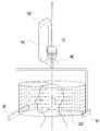
도 1은 본 발명의 한 실시예에 따른 CT 촬영 장치의 촬영 궤적을 보이는 모식도이다.
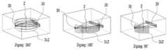
도 2는 상기 도 1의 실시예에 있어서, 다양한 각도 범위가 적용된 CT 촬영 궤적을 보이는 모식도이다.
도 3은 본 발명의 한 실시예에 따른 CT 촬영 장치를 보이는 사시도이다.
도 4는 상기 도 3의 실시예에 따른 CT 촬영 장치의 촬영 궤적 일부를 보이는 모식도이다.
도 5는 본 발명의 한 실시예에 따른 CT 촬영 장치에서 제 2 대면부 회전시 제 1 대면부 내의 제 1 궤적을 보이는 모식도이다.
도 6은 본 발명의 한 실시예에 따른 CT 촬영 장치에서 제 2 대면부 회전시 제1 대면부 내의 제 2 궤적을 보이는 모식도이다.
도 7은 본 발명의 한 실시예에 따른 CT 촬영 장치에서 제 2 대면부 회전시 제 1 대면부 내의 제 3 궤적을 보이는 모식도이다.
도 8은 본 발명의 한 실시예로서 곡면 센서를 갖는 CT 촬영 장치의 촬영 궤적 일부를 보이는 모식도이다.BRIEF DESCRIPTION OF THE DRAWINGS FIG. 1 is a schematic view showing an imaging locus of a CT photographing apparatus according to an embodiment of the present invention; FIG.
FIG. 2 is a schematic view showing a CT photographing trajectory to which various angular ranges are applied in the embodiment of FIG.
3 is a perspective view showing a CT photographing apparatus according to an embodiment of the present invention.
4 is a schematic view showing a part of a photographing trajectory of the CT photographing apparatus according to the embodiment of FIG.
FIG. 5 is a schematic view showing a first trajectory in the first facing portion when the second facing portion rotates in the CT photographing apparatus according to an embodiment of the present invention. FIG.
FIG. 6 is a schematic view showing a second locus in the first facing portion when the second facing portion rotates in the CT photographing apparatus according to an embodiment of the present invention. FIG.
7 is a schematic view showing a third trajectory in the first facing portion during the second facing portion rotation in the CT photographing apparatus according to an embodiment of the present invention.
FIG. 8 is a schematic view showing a part of a photographing trajectory of a CT photographing apparatus having a curved surface sensor as an embodiment of the present invention.
이하에서는 첨부한 도면을 참조하여 본 발명의 실시예를 설명한다. 다음에서 설명되는 실시예들은 여러 가지 다양한 형태로 변형할 수 있으며, 본 발명의 범위가 이하의 실시예에 한정되는 것은 아니다. 본 발명의 실시예는 해당 분야에서 통상의 지식을 가진 자에게 발명의 기술적 사상을 명확히 전달하기 위하여 제공되는 것이다.Hereinafter, embodiments of the present invention will be described with reference to the accompanying drawings. The embodiments described below can be modified into various forms, and the scope of the present invention is not limited to the following embodiments. The embodiments of the present invention are provided to clearly convey the technical idea of the present invention to those skilled in the art.
도 1은 본 발명의 한 실시예에 따른 CT 촬영 장치의 촬영 궤적을 보이는 모식도이다. 도면에 도시된 바와 같이, 엑스선 센서(20)와 엑스선 제너레이터(30)가 피검체를 사이에 두고 서로 대향하도록, 즉 서로 마주보게 설치된다.BRIEF DESCRIPTION OF THE DRAWINGS FIG. 1 is a schematic view showing an imaging locus of a CT photographing apparatus according to an embodiment of the present invention; FIG. As shown in the figure, the
도 1에 보인 실시예와 같이, 상기 엑스선 센서(20)와 엑스선 제너레이터(30)는 피검체를 사이에 두고 서로 대향하는 상태를 유지하면서 소정의 각도 범위에서 지그재그 형태의 궤적(31Z)을 그리며 상기 피검체를 스캔한다.1, the
도 1에서는, 편의상 상기 엑스선 센서(20)와 엑스선 제너레이터(30)의 회전축의 방향을 피검체의 종축(Z) 방향으로 도시하였으나, 실제 본 발명의 실시예에 따른 CT 촬영 장치에서 회전축의 방향은 이와 같을 수도 있고, 피검체의 종축(Z)에 대하여 적어도 소정의 기울기를 가질 수 있다. 또한, 회전축은 도 1에 도시한 바와 같이 회전축은 엑스선 센서(20)와 엑스선 제너레이터(30) 사이에 위치하는 예뿐만 아니라, 회전축은 엑스선 센서(20)에, 엑스선 제너레이터(30)에, 엑스선 센서(20)와 엑스선 제너레이터(30) 사이에도 있을 수 있다.Although the direction of the rotation axis of the
본 발명에 따른 CT 촬영 장치는 엑스선 센서(20)와 엑스선 제너레이터(30)가 소정의 각도 범위에서 왕복 회전되면서 엑스선 센서(20)와 엑스선 제너레이터(30)가 종축(Z) 방향으로 이동되는 경우를 살펴보며, 그 밖의 다른 예에 대해서는 이하의 설명을 통해 당업자라면 쉽게 이해할 수 있을 것이다. 예컨대, 상기 엑스선 센서(20)와 상기 엑스선 제너레이터(30)의 왕복 회전은 제 1 구동부(D1)가 엑스선 센서(20)와 엑스선 제너레이터(30) 중 적어도 어느 하나를 Z축에 대해 회전 운동(MC)시켜 피검체를 투과하는 엑스선 빔이 센서에 수광되는 모든 동작을 포함하는 것으로 이해될 수 있을 것이다. 상기 엑스선 센서(20)는 치과용 엑스선 촬영 장치의 파노라마 촬영용 센서와 같이 바(bar) 형태의 센서를 파노라마 촬영시의 배치 각도로부터 90도 회전시켜 피검체의 종축 방향에 대해 수직을 이루도록 배치된 것일 수 있다. 또한, 상기 엑스선 센서(20)는 콘빔(cone beam) 타입의 엑스선 제너레이터에 대응되는 대면적 센서일 수도 있다. 단일 슬라이스의 엑스선 영상 정보를 취득하는 것에서부터 MDCT(Multiple Detector Computed Tomography)와 같이 멀티 슬라이스의 엑스선 영상 정보를 취득할 수 있는 다양한 종횡비를 가지는 센서가 채용될 수 있다. 엑스선 센서(20)는 피검체를 향하는 부분이 오목한 호 형상의 곡면 센서일 수도 있다.The CT photographing apparatus according to the present invention includes a case where the
상기 엑스선 제너레이터(30)는 엑스선 방출원으로서, 대응되는 엑스선 센서(20)의 형상에 따라 콜리메이션된 엑스선 빔을 방출하는 엑스선 방출원일 수 있다.The
상기 제 1 구동부는 엑스선 빔의 조사 및/또는 수광 방향이 피검체의 종축(Z)을 중심으로 회전되는 결과를 나타내도록 상기 엑스선 센서(20) 또는 상기 엑스선 제너레이터(30)를 회전하도록 구성될 수 있다. 이때, 상기 엑스선 센서(20)와 상기 엑스선 제너레이터(30) 중 어느 하나를 이동시키거나, 둘을 각각 운동시키도록 구성될 수도 있다. 왕복 회전운동으로 피검체에 대한 엑스선 빔의 조사 방향 또는 수광 방향을 이동시키면서, 상기 엑스선 센서(20)와 엑스선 제너레이터(30)가 서로 대향하는 상대적 위치 관계를 유지하도록 구성되는 것이면 된다.The first driver may be configured to rotate the
본 발명에 따른 CT 장치는 치과용 엑스선 촬영 장치의 회전암 또는 그에 상응하는 구조물을 피검체의 종축 방향(MZ)으로 이동시키기 위한 제2 구동부(D2)가 더 포함될 수 있다. 제2 구동부는 상기 엑스선 센서(20)와 상기 엑스선 제너레이터(30) 각각을 가이드하는 구조물을 피검체의 종축 방향으로 이동시키도록 구성될 수도 있다. 이들의 구체적인 구성 예에 대해서는 후술하기로 하며, 개시된 예들을 포함하여 다양한 형태로 구현될 수 있다.The CT apparatus according to the present invention may further include a second driving unit D2 for moving the rotary arm of the dental X-ray imaging apparatus or the corresponding structure to the longitudinal axis MZ of the subject. The second driving unit may be configured to move the structure guiding the
상기 소정의 각도 범위는 CT 영상의 재구성 방식 및 장치 특성에 따라 미리 정해질 수 있으며, 일정한 최대 값의 범위 내에서 CT 영상을 촬영하고자 하는 목적이나 피검체의 특성에 따라 조정될 수도 있다. 다만, 여기서 일정한 최대값은 360도 미만일 수 있으며, 약 30도 내지 약 90도의 범위에서 구현될 수도 있다.The predetermined angular range may be predetermined according to the CT image reconstruction method and apparatus characteristics, and may be adjusted according to the purpose of imaging the CT image or the characteristics of the subject within a predetermined maximum value range. However, the predetermined maximum value may be less than 360 degrees, and may be implemented in a range of about 30 degrees to about 90 degrees.
도 2는 상기 도 1의 실시예에 있어서, 다양한 각도 범위가 적용된 CT 촬영 궤적을 보이는 모식도이다. 본 도면에 표시된 궤적(31Z)은 엑스선 제너레이터(30)의 위치를 기준으로 한 것으로서, 전술한 제 1 구동부에 의한 부분 회전 왕복 운동의 각도 범위에 따라, 360도, 180도, 90도, 또는 이들 사이의 임의의 각도 범위에서 지그재그 형 궤적(31Z)이 만들어질 수 있다.FIG. 2 is a schematic view showing a CT photographing trajectory to which various angular ranges are applied in the embodiment of FIG. The
한편, 상기 도 1 및 도 2에 도시된 지그재그형 궤적(31Z)은 상기 제 1 구동부와 상기 제 2 구동부가 동시에 작동하는 경우에 해당하는 것으로, 왕복 운동의 방향이 바뀌는 부분에서 Z자형으로 꺾이는 형태를 보이고 있으나, 이와 달리 상기 제 1 구동부와 상기 제 2 구동부가 교대로 작동하는 경우에는 왕복 운동의 방향이 바뀌는 부분에서 ㄹ자형으로 꺾이는 형태를 보일 수도 있다.The
도 3은 본 발명의 한 실시예에 따른 CT 촬영 장치를 보이는 사시도이다. 본 실시예에 따른 CT 촬영 장치는, 바닥면에 대해 고정되게 설치되는 컬럼(100)과, 상기 컬럼(100)의 일측에 피검체(H)를 향해 배치되고, 엑스선 센서(20)를 포함하는 제 1 대면부(25)와, 상기 컬럼(100)에 대하여 적어도 소정의 각도 범위에서 회전할 수 있도록 연결되는 회전암(45), 그리고 상기 회전암(45)에서 상기 컬럼(100)으로부터 먼 쪽에 상기 피검체(H)를 사이에 두고 상기 제 1 대면부(25)와 마주보게 배치되고, 엑스선 제너레이터(30)를 포함하는 제 2 대면부(35)를 포함한다.3 is a perspective view showing a CT photographing apparatus according to an embodiment of the present invention. The CT photographing apparatus according to the present embodiment includes a
본 실시예에 따른 CT 촬영 장치는, 상기 회전암(45)과 상기 컬럼(100)을 연결하며, 상기 회전암(45)을 상기 컬럼(100)에 대하여 고정된 한 축(A1)을 중심으로 회전시키는 회전 구동부를 더 포함하고, 상기 제 1 대면부(25)를 상기 컬럼(100)의 길이 방향(d25)으로 이동시킬 수 있는 직선 구동부(도시하지 않음)를 더 포함할 수 있다. 한편, 상기 직선 구동부는 상기 회전암(45)를 상기 제 1 대면부(25)와 동시에 이동시킴으로써 상기 제 2 대면부(35) 내의 엑스선 제너레이터(30)와 상기 제 1 대면부(25) 내의 엑스선 센서(20)가 피검체의 종축(Z) 방향(여기서는 상기 컬럼(100)의 길이 방향과 평행함)으로 이동하도록 할 수 있다.The CT photographing apparatus according to the present embodiment is configured to connect the
상기 엑스선 센서(20)는 상기 제 1 대면부(25) 내에서 소정의 궤적(21)을 따라 이동하도록 설치될 수 있다. 예컨대, 상기 엑스선 센서(20)가 상기 회전암(45)의 회전에 연동하여 상기 제 1 대면부(25)의 케이스에 마련된 레일(rail) 또는 랙(rack)을 따라 이동하면서 상기 엑스선 제너레이터(30)와 서로 대향하도록 설치될 수 있다.The
상기 제 1 대면부(25)에는 피검체인 환자의 머리 부분을 고정하기 위한 구조물, 예컨대 바이트 블럭이나 헤드 레스트, 또는 템플 서포트 등이 설치될 수 있다. 한편, 엑스선 제너레이터(30)를 포함하는 상기 제 2 대면부(35)는 컬럼(100) 내에 있는 회전축(A2)을 중심으로 회전할 수 있도록 설치될 수도 있다.A structure for fixing the head portion of the patient to be examined, for example, a bite block, a headrest, a temple support, or the like may be provided on the first facing
상기 제 2 대면부(35)가 상기 회전암(45)의 몸체에 대해 고정된 경우, 상기 엑스선 제너레이터(30)에서 방출된 엑스선 빔(B)의 중심은 항상 상기 회전암(45)의 회전축(A1)을 향하게 되므로 엑스선 빔(B)의 중심이 피검체(H) 및 엑스선 센서(20)로부터 벗어날 수는 있으나, 엑스선 빔(B)의 조사 범위가 상기 피검체(H) 및 상기 엑스선 센서(20)를 벗어나지 않는 범위에서 상기 회전암(45)의 왕복 회전이 가능하다. 또한, 상기 제 2 대면부(35)가 상기 회전암(45)의 몸체와 별도로 회전하는 경우, 상기 회전암(45)이 회전함에 따라 상기 엑스선 제너레이터(30)에서 방출된 엑스선 빔(B)이 상기 피검체(H) 쪽을 향하도록 상기 제 2 대면부(35)를 회전축(A2) 중심으로 회전시킬 수 있다.The center of the x-ray beam B emitted from the
본 실시예에 있어서, 상기 회전암(45)을 회전시키는 회전 구동부, 그와 연동하여 엑스선 제너레이터(30)와 엑스선 센서(20)가 피검체를 사이에 두고 서로 대향하도록 이들을 이동 또는 회전시키는 기계적 요소들이 전술한 제 1 구동부에 해당한다. 아울러, 상기 엑스선 제너레이터(30)와 상기 엑스선 센서(20)를 피검체의 종축 방향으로 직선 이동시키는 기계적 요소들이 전술한 제 2 구동부에 해당하며, 그 구체적인 구성은 본 실시예에 개시된 것 외에도 다양하게 변형될 수 있다.In this embodiment, a rotation driving unit for rotating the
도 4는 상기 도 3의 실시예에 따른 CT 촬영 장치의 촬영 궤적 일부를 보이는 모식도이다. 본 도면을 통해 상기 회전암(45)이 소정 각도의 범위에서 회전할 때, 상기 엑스선 센서(20)의 궤적(21)과 상기 엑스선 제너레이터(30)의 궤적(31) 및 피검체(H)를 포함한 이들의 위치 관계를 볼 수 있다. 전술한 바와 같이, 상기 엑스선 센서(20)는 상기 회전암(45)의 회전에 연동하여 일정한 궤적(21)을 따라 이동하며, 그 위치 및 각도가 바뀌도록 설치될 수 있다. 이를 통해, 상기 회전암(45)이 임의의 위치에 있을 때, 상기 엑스선 센서(20)는 전부 또는 적어도 그 일부가 상기 엑스선 제너레이터(30)에서 방출된 엑스선 빔(B)의 조사 영역 내에서 피검체(H)를 사이에 두고 상기 엑스선 제너레이터(30)와 서로 마주보도록 위치할 수 있다.4 is a schematic view showing a part of a photographing trajectory of the CT photographing apparatus according to the embodiment of FIG. The
한편, 상기 엑스선 제너레이터(30) 역시 상기 회전암(45)에 고정된 한 축(A2)를 중심으로, 상기 회전암(45)의 회전에 연동하여 점선으로 표시된 화살표(d35) 방향으로 회전함으로써, 엑스선 빔(B)이 상기 컬럼(100) 상의 회전축(A1)이 아닌 피검체(H) 쪽을 향하도록 할 수도 있다.The
상기 엑스선 제너레이터(30) 또는 상기 엑스선 제너레이터(30)가 설치된 제 2 대면부(35)가 상기 회전암(45)의 회전에 따라 피검체(H) 쪽을 향하도록 회전하는 경우, 상기 제 1 대면부(25)에 이동 가능하게 설치된 엑스선 센서(20)는 여러 가지 궤적을 따라 이동할 수 있다. 이하에서는 여러 가지 궤적의 형태에 관하여 몇 가지 예를 들어 설명한다. 다만, 여기에 설명된 몇 가지 예에 한정되는 것은 아니다.When the second facing
이하에서 설명할 실시예에서도 상기 도 3 및 도 4의 실시예와 마찬가지로 제 1 대면부(미도시)에 엑스선 센서(20)가, 제 2 대면부(35)에 엑스선 제너레이터(30)가 배치될 수 있다. 상기 엑스선 제너레이터(30)는 상기 회전암(45)이 회전하더라도 빔의 중심이 피검체(H)의 중심을 향하도록 상기 제 2 대면부(35)가 회전축(A2)을 중심으로 회전할 수 있다.In the embodiments described below, the
도 5는 본 발명의 한 실시예에 따른 CT 촬영 장치에서 제 2 대면부 회전시 제 1 대면부 내의 제 1 궤적을 보이는 모식도이다. 회전암의 회전에 따라 제 2 대면부(35)의 위치가 원호 형태의 엑스선 제너레이터 궤적(31)을 따라 변할 때, 상기 제 2 대면부(35)는 전술한 바와 같이 그 회전축(A2)을 중심으로 회전하여 엑스선 제너레이터(30)에서 조사된 엑스선 빔의 중심부가 피검체(H)의 중심축(Z)을 지나도록 할 수 있다. 엑스선 센서(20)는 그 중심이 상기 엑스선 빔의 중심부에 대응되도록 이동하며, 방향은 상기 엑스선 제너레이터(30)와 대향하도록 할 수 있다. 이때, 상기 엑스선 센서(20)는 피검체(H) 종축(Z)과의 거리(ZS1)를 반지름으로 한 원호 형태인 엑스선 센서 제 1 궤적(211)을 따라 이동할 수 있다.FIG. 5 is a schematic view showing a first trajectory in the first facing portion when the second facing portion rotates in the CT photographing apparatus according to an embodiment of the present invention. FIG. When the position of the second facing
엑스선 영상 촬영시에 영상의 확대율을 엑스선 제너레이터(30)에서 피검체(H)까지의 거리와 엑스선 제너레이터(30)에서 엑스선 센서(20)까지의 거리의 비 즉, GZ:GS1에 의해서 정해진다. 엑스선 제너레이터(30)가 원호형의 엑스선 제너레이터 궤적(31)을 따라 이동할 때, GZ값은 그 위치에 따라 변하고, GS1는 GS1=GZ+ZS1의 관계를 만족한다. 엑스선 센서(20)가 상기 제 1 궤적(211)을 따라 움직일 때 ZS1은 상수이므로, 확대율은 GZ:GS1=1:1+(ZS1/GZ)로서, GZ값의 변화에 따라(촬영시 엑스선 제너레이터(30)의 위치에 따라) 변한다. 여러 각도에서 촬영된 다수의 엑스선 투과 영상을 재구성하여 CT 영상을 얻는 CT 촬영 장치에 있어서, 다수의 엑스선 투과 영상들은 확대율이 일정할 필요가 있으므로, 각각의 엑스선 투과 영상 촬영시에 확대율 정보를 취득하고 영상 재구성 전에 이를 이용하여 확대율을 보정할 수 있다.The enlargement ratio of the image at the time of taking an X-ray image is determined by the ratio of the distance from the
도 6은 본 발명의 한 실시예에 따른 CT 촬영 장치에서 제 2 대면부 회전시 제1 대면부 내의 제 2 궤적을 보이는 모식도이다. 상기 제 2 대면부(35)의 움직임과 상기 엑스선 제너레이터 궤적(31), 그리고 엑스선 센서(20)의 중심이 상기 엑스선 제너레이터(30)에서 조사된 상기 엑스선 빔의 중심부에 대응되도록 이동하며, 상기 엑스선 제너레이터(30)와 대향하도록 움직인다는 점에서는 상기 도 5의 실시예와 동일하다. 다만, 본 실시예에 있어서, 상기 엑스선 센서(20)의 중심의 이동을 나타내는 엑스선 센서 제 2 궤적(212)의 특징은, 상기 엑스선 제너레이터(30)와 상기 엑스선 센서(20) 사이의 거리(GS2)가 항상 일정하게 유지된다는 점이다.FIG. 6 is a schematic view showing a second locus in the first facing portion when the second facing portion rotates in the CT photographing apparatus according to an embodiment of the present invention. FIG. The movement of the second facing
본 실시예에 따른 CT 촬영 장치에서 확대율은 GZ:GS2이고, 여기, GS2는 상수이다. 엑스선 제너레이터(30)가 회전암의 회전축(A1)과 피검체(H) 종축(Z)의 연장선상에 있을 때, GZ의 값은 최소가 되고 확대율은 최대가 되며, 상기 엑스선 제너레이터(30)가 그 위치로부터 엑스선 제너레이터 궤적(31)을 따라 좌 또는 우로 회전하면 GZ값이 조금씩 커지면서 확대율은 감소한다. 본 실시예의 경우에도, CT 영상 재구성을 위해서는 이러한 확대율의 변화를 고려하여 이를 보정할 수 있다.In the CT photographing apparatus according to the present embodiment, the enlargement ratio is GZ: GS2, and GS2 is a constant. When the
도 7은 본 발명의 한 실시예에 따른 CT 촬영 장치에서 제 2 대면부 회전시 제 1 대면부 내의 제 3 궤적을 보이는 모식도이다. 상기 제 2 대면부(35)의 움직임과 상기 엑스선 제너레이터 궤적(31), 그리고 엑스선 센서(20)의 중심이 상기 엑스선 제너레이터(30)에서 조사된 상기 엑스선 빔의 중심부에 대응되도록 이동하며, 상기 엑스선 제너레이터(30)와 대향하도록 움직인다는 점에서는 상기 도 5의 실시예와 동일하다. 다만, 상기 엑스선 센서(20)의 중심의 이동을 나타내는 엑스선 센서 제 3 궤적(213)을 설계함에 있어서, 상기 엑스선 제너레이터(30)가 상기 그 궤적(31) 상에서 여러 위치로 이동하더라도 엑스선 투과 영상의 확대율이 일정하게 유지되도록 할 수 있다.7 is a schematic view showing a third trajectory in the first facing portion during the second facing portion rotation in the CT photographing apparatus according to an embodiment of the present invention. The movement of the second facing
엑스선 투과 영상의 확대율, 즉 GZ:GS3가 일정한 값을 갖도록 하기 위해서는, 엑스선 제너레이터(30)의 위치에 따라 GZ값이 변할 때, 그 변화율과 같은 비율로 GS3를 변화시킬 수 있다. 이 경우, 엑스선 제너레이터(30)가 회전암의 회전축(A1)과 피검체(H) 종축(Z)의 연장선상에 있을 때, GZ의 값은 최소가 되고, 그 때 피검체(H)와 엑스선 센서(20)의 거리(ZS3)도 최소가 된다. 따라서 이 위치에서 엑스선 센서(20)가 피검체(H)의 표면에 부딪치지 않도록 할 필요가 있다. 본 실시예에 따른 CT 촬영 장치에서는 여러 각도에서 촬영된 엑스선 투과 영상들의 확대율이 일정하게 유지되므로, CT 영상 재구성시에 별도의 확대율 보정 없이 재구성이 가능하다.In order to make the enlargement ratio of the X-ray transmission image, that is, GZ: GS3 to be a constant value, when the GZ value changes according to the position of the
도 8은 본 발명의 한 실시예로서 곡면 센서를 갖는 CT 촬영 장치의 촬영 궤적 일부를 보이는 모식도이다. 본 실시예는 상기 도 3 내지 4에서 도시된 실시예에서 평면형의 엑스선 센서(20) 대신 곡면 센서(22)를 채용했다는 점에 차이가 있다. 상기 곡면 센서(22)는 상기 회전암(45)의 회전 각도 범위에 대하여, 적어도 일부분이 상기 피검체(H)를 사이에 두고 상기 엑스선 제너레이터(30)와 정면으로 마주보도록 형성된 것일 수 있으며, 전술한 도 3 내지 도 4의 실시예에서 상기 엑스선 센서(20)가 궤적(21)을 따라 이동하며 커버하는 전 영역을 고정적으로 커버할 수 있도록 설치될 수 있다.FIG. 8 is a schematic view showing a part of a photographing trajectory of a CT photographing apparatus having a curved surface sensor as an embodiment of the present invention. The present embodiment differs from the embodiment shown in Figs. 3 to 4 in that a
한편, 상기 도 4 내지 도 8에서는 엑스선 센서(20, 22)의 형태 또는 이동 궤적(21, 211, 212, 213)을 좀 더 명확히 볼 수 있도록 하기 위하여 제 1 대면부(25)(도 3 참조)를 생략하고 도시하였다.4 to 8, in order to more clearly see the shape or
H: 피검체B: 엑스선 빔
20: 엑스선 센서21: 엑스선 센서 궤적
211: 엑스선 센서 제 1 궤적
212: 엑스선 센서 제 2 궤적
213: 엑스선 센서 제 3 궤적
22: 곡면 센서25: 제 1 대면부
30: 엑스선 제너레이터31: 엑스선 제너레이터 궤적
35: 제 2 대면부H: subject B: X-ray beam
20: X-ray sensor 21: X-ray sensor locus
211: X-ray sensor first locus
212: X-ray sensor second locus
213: X-ray sensor third trajectory
22: curved surface sensor 25: first surface section
30: X-ray generator 31: X-ray generator locus
35: second facing surface
Claims (10)
Translated fromKorean상기 컬럼의 일측에 피검체를 향해 배치되고, 엑스선 제너레이터 및 엑스선 센서 중 어느 하나를 포함하는 제 1 대면부;
상기 피검체에 대하여 적어도 소정의 각도 범위에서 회전할 수 있도록 연결되는 회전암; 및
상기 피검체를 사이에 두고 상기 제 1 대면부와 마주보도록 상기 회전암의 일단에 배치되는 상기 엑스선 제너레이터 및 엑스선 센서 중 나머지 하나를 포함하는 제 2 대면부를 포함하는 CT 촬영 장치.
column;
A first facing portion disposed on one side of the column toward the subject and including any one of an x-ray generator and an x-ray sensor;
A rotary arm connected to the subject so as to be rotatable at least in a predetermined angular range; And
And a second facing portion including the other one of the X-ray generator and the X-ray sensor disposed at one end of the rotary arm so as to face the first facing portion with the body therebetween.
상기 엑스선 제너레이터 및 엑스선 센서는, 상기 회전암이 상기 소정의 각도 범위 내에 있을 때, 상기 엑스선 센서의 적어도 일부가 상기 엑스선 제너레이터의 엑스선 조사 범위 내에서 상기 피검체를 사이에 두고 상기 엑스선 제너레이터와 마주보도록 설치되는, CT 촬영 장치.
The method according to claim 1,
The X-ray generator and the X-ray sensor are arranged such that when the rotary arm is within the predetermined angular range, at least a part of the X-ray sensor faces the X-ray generator across the body within the X-ray irradiation range of the X- Installed, CT imaging device.
상기 엑스선 센서는 상기 제 1 대면부에 설치되고,
상기 엑스선 제너레이터는 상기 제 2 대면부에 설치된, CT 촬영 장치.
The method according to claim 1,
Wherein the X-ray sensor is installed in the first facing portion,
And the x-ray generator is installed in the second facing portion.
상기 엑스선 센서는 상기 제 1 대면부 내에서 상기 회전암의 회전 방향에 따라 이동하여, 적어도 일부가 상기 엑스선 제너레이터의 엑스선 조사 범위 내에서 상기 피검체를 사이에 두고 상기 엑스선 제너레이터와 마주보도록 설치되는, CT 촬영 장치.
The method of claim 3,
Wherein the X-ray sensor is disposed in the first facing portion so as to move along the rotational direction of the rotary arm and at least a part of the X-ray sensor faces the X-ray generator across the body of the X- CT imaging device.
상기 엑스선 센서는 상기 피검체로부터의 거리가 일정한 궤적을 따라 이동하는, CT 촬영 장치.
The method of claim 4,
And the X-ray sensor moves along a locus having a constant distance from the subject.
상기 엑스선 센서는 상기 엑스선 제너레이터로부터의 거리가 일정한 궤적을 따라 이동하는, CT 촬영 장치.
The method of claim 4,
Wherein the X-ray sensor moves along a locus having a constant distance from the X-ray generator.
상기 엑스선 센서는, 상기 엑스선 제너레이터로부터의 상기 피검체까지의 거리 대 상기 엑스선 제너레이터로부터 상기 엑스선 센서까지 거리의 비가 상수인 궤적을 따라 이동하는, CT 촬영 장치.
The method of claim 4,
Wherein the X-ray sensor moves along a locus where a ratio of a distance from the X-ray generator to the subject to a distance from the X-ray generator to the X-ray sensor is a constant.
상기 엑스선 센서는 상기 회전암의 회전 각도 범위에 대하여, 적어도 일부가 상기 피검체를 사이에 두고 상기 엑스선 제너레이터와 마주보도록 형성된 곡면 센서인, CT 촬영 장치.
The method of claim 3,
Wherein the X-ray sensor is a curved surface sensor formed such that at least a part of the X-ray sensor is opposed to the X-ray generator with respect to the rotational angle range of the rotary arm with the body being interposed therebetween.
상기 제 2 대면부를 소정의 각도 범위에서 왕복 회전시키는 제 1 구동부; 및
상기 제 1 구동부와 동시 또는 교대로 작동하여 상기 제 1 대면부 또는 상기 제 2 대면부 중 적어도 하나를 상기 피검체의 종축 방향으로 이동시키는 제 2 구동부를 더 포함하는, CT 촬영 장치.
The method according to claim 1,
A first driving unit that reciprocally rotates the second facing portion in a predetermined angular range; And
Further comprising a second driving unit that operates simultaneously or alternately with the first driving unit to move at least one of the first facing portion and the second facing portion in the longitudinal direction of the test subject.
상기 제 1 구동부는, 상기 컬럼과 상기 회전암을 연결하며 상기 컬럼에 고정된 축을 중심으로 상기 회전암을 회전시키는 회전 구동부이고,
상기 제 2 구동부는, 상기 제 1 대면부 또는 상기 제 2 대면부 중 적어도 하나를 상기 컬럼에 대하여 승강시키는 직선 구동부인, CT 촬영 장치.The method of claim 9,
The first driving unit is a rotation driving unit that connects the column and the rotary arm and rotates the rotary arm about an axis fixed to the column,
Wherein the second driving unit is a linear driving unit that elevates and lowers at least one of the first facing portion and the second facing portion with respect to the column.
Priority Applications (4)
| Application Number | Priority Date | Filing Date | Title |
|---|---|---|---|
| KR1020140009244AKR20150088679A (en) | 2014-01-24 | 2014-01-24 | Apparatus for Obtaining Computed Tomography |
| PCT/KR2015/000807WO2015111979A1 (en) | 2014-01-24 | 2015-01-26 | Ct photographic device |
| US15/113,783US10265033B2 (en) | 2014-01-24 | 2015-01-26 | CT photographic device comprising a rotary driving part and a linear driving part |
| EP15740403.9AEP3097854B1 (en) | 2014-01-24 | 2015-01-26 | Ct photographic device |
Applications Claiming Priority (1)
| Application Number | Priority Date | Filing Date | Title |
|---|---|---|---|
| KR1020140009244AKR20150088679A (en) | 2014-01-24 | 2014-01-24 | Apparatus for Obtaining Computed Tomography |
Publications (1)
| Publication Number | Publication Date |
|---|---|
| KR20150088679Atrue KR20150088679A (en) | 2015-08-03 |
Family
ID=53681697
Family Applications (1)
| Application Number | Title | Priority Date | Filing Date |
|---|---|---|---|
| KR1020140009244ACeasedKR20150088679A (en) | 2014-01-24 | 2014-01-24 | Apparatus for Obtaining Computed Tomography |
Country Status (4)
| Country | Link |
|---|---|
| US (1) | US10265033B2 (en) |
| EP (1) | EP3097854B1 (en) |
| KR (1) | KR20150088679A (en) |
| WO (1) | WO2015111979A1 (en) |
Cited By (2)
| Publication number | Priority date | Publication date | Assignee | Title |
|---|---|---|---|---|
| KR20200125108A (en) | 2019-04-26 | 2020-11-04 | 주식회사 나노레이 | Spiral rotating CT apparatus for dental |
| KR20220087276A (en) | 2020-12-17 | 2022-06-24 | 주식회사 나노레이 | Low-dose CT driving device |
Families Citing this family (7)
| Publication number | Priority date | Publication date | Assignee | Title |
|---|---|---|---|---|
| US9888891B2 (en) | 2014-06-26 | 2018-02-13 | Palodex Group Oy | X-ray imaging unit for medical imaging |
| CN104198506B (en)* | 2014-08-27 | 2017-11-07 | 清华大学 | Low-angle is from pendulum-type large-sized multiple layer helical CT device and inspection method |
| EP3261543B1 (en)* | 2015-02-27 | 2024-03-27 | Trophy | Bite block for cbct imaging device |
| KR101725642B1 (en)* | 2015-07-17 | 2017-04-11 | 오스템임플란트 주식회사 | X-ray photographing apparatus and method |
| KR102043357B1 (en)* | 2017-10-18 | 2019-11-12 | 오스템임플란트 주식회사 | A method for changing a scale of an image and an apparatus for the same |
| JP7128488B2 (en)* | 2020-10-06 | 2022-08-31 | フジキンソフト株式会社 | X-ray equipment |
| JP7458613B2 (en)* | 2021-05-11 | 2024-04-01 | 学校法人日本大学 | Panoramic X-ray imaging device |
Family Cites Families (47)
| Publication number | Priority date | Publication date | Assignee | Title |
|---|---|---|---|---|
| US5214686A (en)* | 1991-12-13 | 1993-05-25 | Wake Forest University | Three-dimensional panoramic dental radiography method and apparatus which avoids the subject's spine |
| EP0858773B1 (en)* | 1997-02-17 | 2002-09-11 | Sirona Dental Systems GmbH | Device for producing X-rays of parts of a human body |
| EP0904734A3 (en)* | 1997-09-30 | 2000-03-29 | Kabushikikaisha Morita Seisakusho | Panoramic radiographic apparatus and digital sensor cassette used for same apparatus |
| JP3919048B2 (en)* | 1998-09-02 | 2007-05-23 | 株式会社モリタ製作所 | Local irradiation X-ray CT imaging system |
| JP4015366B2 (en)* | 1999-03-25 | 2007-11-28 | 学校法人日本大学 | Local irradiation X-ray CT imaging method and apparatus |
| DE10008053A1 (en)* | 2000-02-22 | 2001-09-06 | Siemens Ag | X-ray device and medical workplace for diagnostics and for surgical interventions in the head and jaw area of a patient |
| JP2003175027A (en)* | 2001-12-10 | 2003-06-24 | Hitachi Medical Corp | X-ray ct system |
| ATE376389T1 (en)* | 2002-02-15 | 2007-11-15 | Breakaway Imaging Llc | GANTRY RING WITH REMOVABLE SEGMENT FOR MULTI-DIMENSIONAL X-RAY IMAGING |
| US7188998B2 (en)* | 2002-03-13 | 2007-03-13 | Breakaway Imaging, Llc | Systems and methods for quasi-simultaneous multi-planar x-ray imaging |
| AU2003224711A1 (en)* | 2002-03-19 | 2003-10-08 | Breakaway Imaging, Llc | Computer tomograph with a detector following the movement of a pivotable x-ray source |
| DE10313110A1 (en)* | 2003-03-24 | 2004-10-21 | Sirona Dental Systems Gmbh | X-ray device and X-ray sensitive camera |
| DE10313109A1 (en)* | 2003-03-24 | 2004-10-21 | Sirona Dental Systems Gmbh | X-ray sensitive camera and X-ray device |
| JP2005087592A (en)* | 2003-09-19 | 2005-04-07 | Hitachi Ltd | X-ray measuring device |
| US6990174B2 (en)* | 2003-12-15 | 2006-01-24 | Instrumentarium Corp. | Method and apparatus for performing single-point projection imaging |
| DE102004012243B4 (en)* | 2004-03-12 | 2007-11-15 | Siemens Ag | Computed tomography device with movable detector aperture |
| FI118624B (en)* | 2005-03-14 | 2008-01-31 | Planmeca Oy | Orthodontic computed tomography imaging |
| CN2796650Y (en)* | 2005-03-31 | 2006-07-19 | 西门子(中国)有限公司 | Computer tomography system capable of regulating distance of focus to detector |
| US7711085B2 (en)* | 2005-04-11 | 2010-05-04 | J. Morita Manufacturing Corporation | Radiography apparatus with scout view function |
| JP4307406B2 (en)* | 2005-04-22 | 2009-08-05 | 株式会社モリタ製作所 | Medical X-ray imaging apparatus and X-ray detector used therefor |
| FI20085470A7 (en)* | 2005-10-17 | 2008-05-19 | J Morita Mfg Corp | Medical digital X-ray imaging device and medical digital X-ray sensor |
| WO2007046458A1 (en)* | 2005-10-21 | 2007-04-26 | Axion Japan Co., Ltd | Panoramic image capturing device and image processing method for panoramic image capturing |
| WO2008035828A1 (en)* | 2006-09-22 | 2008-03-27 | Ray Co., Ltd. | Dental complex imaging system |
| US7486759B2 (en)* | 2006-10-12 | 2009-02-03 | J. Morita Manufacturing Corporation | X-ray computer tomography apparatus |
| US7787586B2 (en)* | 2007-02-22 | 2010-08-31 | J. Morita Manufacturing Corporation | Display method of X-ray CT image of maxillofacial area, X-ray CT apparatus and X-ray image display apparatus |
| US7515679B2 (en)* | 2007-06-01 | 2009-04-07 | Qr (Quantitative Radiography) Srl | Method and system for cone beam x-ray source and detector arrangement in computed tomography systems |
| JP2009005984A (en)* | 2007-06-28 | 2009-01-15 | Morita Mfg Co Ltd | X-ray CT imaging system |
| FR2924325B1 (en)* | 2007-12-03 | 2010-11-26 | Trophy | DENTAL RADIOLOGY APPARATUS AND ASSOCIATED METHOD. |
| CN101470086B (en)* | 2007-12-29 | 2012-11-28 | 清华大学 | Detector device and CT inspection system with the detector device |
| FR2927525B1 (en)* | 2008-02-19 | 2011-04-15 | Owandy | DENTAL RADIOGRAPHY DEVICE AND X-RAY SENSOR |
| KR101577475B1 (en)* | 2008-02-20 | 2015-12-14 | 이미징 사이언시즈 인터내셔널 엘엘씨 | Adjustable scanner |
| FR2938182B1 (en)* | 2008-08-22 | 2010-11-19 | Trophy | DENTAL RADIOLOGY APPARATUS AND METHOD OF USE THEREOF |
| FR2938183B1 (en)* | 2008-08-22 | 2011-12-09 | Trophy | PANORAMIC DENTAL RADIOLOGY APPARATUS AND METHOD OF USE THEREOF |
| US8525833B2 (en)* | 2008-10-13 | 2013-09-03 | George Papaioannou | Dynamic biplane roentgen stereophotogrammetric analysis |
| EP2198783B1 (en)* | 2008-12-19 | 2016-10-12 | Cefla S.C. | Apparatus and method for digital X-ray scanning |
| JP5503883B2 (en)* | 2009-03-06 | 2014-05-28 | 株式会社東芝 | X-ray CT apparatus and X-ray detection apparatus |
| US9084568B2 (en)* | 2009-08-05 | 2015-07-21 | Telesystems Co., Ltd. | Radiation imaging apparatus and imaging method using radiation |
| EP2286728B1 (en)* | 2009-08-19 | 2022-03-16 | J. Morita Manufacturing Corporation | Medical x-ray apparatus |
| WO2011095695A1 (en)* | 2010-02-02 | 2011-08-11 | Planmeca Oy | Dental computed tomography apparatus |
| EP2614773B1 (en) | 2010-07-13 | 2018-01-03 | Takara Telesystems Corp. | X-ray tomogram imaging device |
| JP5757660B2 (en)* | 2010-08-11 | 2015-07-29 | 学校法人日本大学 | X-ray equipment |
| JP5711200B2 (en)* | 2011-11-02 | 2015-04-30 | 株式会社モリタ製作所 | Panoramic X-ray tomography apparatus and image processing apparatus |
| KR20140044174A (en)* | 2012-10-04 | 2014-04-14 | 주식회사바텍 | X-ray imaging apparatus and method |
| JP5709820B2 (en)* | 2012-11-08 | 2015-04-30 | 株式会社モリタ製作所 | X-ray equipment |
| JP5756790B2 (en)* | 2012-11-08 | 2015-07-29 | 株式会社モリタ製作所 | X-ray equipment |
| TWI488612B (en)* | 2012-11-20 | 2015-06-21 | Iner Aec Executive Yuan | Apparatus for x-ray photography |
| US9974493B2 (en)* | 2013-08-27 | 2018-05-22 | Vatech Co., Ltd. | Apparatus and method for obtaining computed tomography |
| TWI522088B (en)* | 2013-10-28 | 2016-02-21 | 行政院原子能委員會核能研究所 | A tomographic scanning apparatus |
- 2014
- 2014-01-24KRKR1020140009244Apatent/KR20150088679A/ennot_activeCeased
- 2015
- 2015-01-26WOPCT/KR2015/000807patent/WO2015111979A1/enactiveApplication Filing
- 2015-01-26USUS15/113,783patent/US10265033B2/enactiveActive
- 2015-01-26EPEP15740403.9Apatent/EP3097854B1/enactiveActive
Cited By (2)
| Publication number | Priority date | Publication date | Assignee | Title |
|---|---|---|---|---|
| KR20200125108A (en) | 2019-04-26 | 2020-11-04 | 주식회사 나노레이 | Spiral rotating CT apparatus for dental |
| KR20220087276A (en) | 2020-12-17 | 2022-06-24 | 주식회사 나노레이 | Low-dose CT driving device |
Also Published As
| Publication number | Publication date |
|---|---|
| US10265033B2 (en) | 2019-04-23 |
| EP3097854B1 (en) | 2020-07-08 |
| EP3097854A4 (en) | 2018-03-14 |
| WO2015111979A1 (en) | 2015-07-30 |
| EP3097854A1 (en) | 2016-11-30 |
| US20160345916A1 (en) | 2016-12-01 |
Similar Documents
| Publication | Publication Date | Title |
|---|---|---|
| KR20150088679A (en) | Apparatus for Obtaining Computed Tomography | |
| US11266364B2 (en) | X-ray scatter reducing device for use with 2D mammography and tomosynthesis | |
| JP6546173B2 (en) | X-ray imaging apparatus and X-ray imaging method | |
| US9420975B2 (en) | Imaging facility and radiation therapy device | |
| CN104066376B (en) | Apparatus and method for digital radiography | |
| KR101499267B1 (en) | Dental and Facial Imaging Devices | |
| US7885378B2 (en) | Imaging system and related techniques | |
| KR102368907B1 (en) | X-ray Generator For Intraoral X-ray Photographing and System Comprising The Same | |
| JP5687618B2 (en) | Computer tomography scanner and scanning method | |
| WO2007050025A2 (en) | Method and arrangement relating to x-ray imaging | |
| JP2008528985A (en) | Tomographic machine with variable imaging geometry | |
| CN106132302A (en) | X-ray imaging apparatus including multiple X-ray sources | |
| US9974493B2 (en) | Apparatus and method for obtaining computed tomography | |
| CN113133780B (en) | X-ray imaging device | |
| JP7657854B2 (en) | SYSTEM AND METHOD FOR AN INTEGRATED FILTER ASSEMBLY HAVING TWO CARRIAGES - Patent application | |
| US20220047232A1 (en) | Medical imaging system with contoured detector | |
| KR20180042572A (en) | X-ray Imaging Apparatus Having Convertible Detector Array | |
| JP6113856B2 (en) | X-ray equipment | |
| CN219147628U (en) | Imaging device | |
| CN103750853A (en) | Intelligent multi-degree of freedom ring-direction diagnosing device | |
| KR20200125108A (en) | Spiral rotating CT apparatus for dental | |
| HK1200298B (en) | Apparatus and method for digital radiography |
Legal Events
| Date | Code | Title | Description |
|---|---|---|---|
| PA0109 | Patent application | Patent event code:PA01091R01D Comment text:Patent Application Patent event date:20140124 | |
| PG1501 | Laying open of application | ||
| A201 | Request for examination | ||
| PA0201 | Request for examination | Patent event code:PA02012R01D Patent event date:20190123 Comment text:Request for Examination of Application Patent event code:PA02011R01I Patent event date:20140124 Comment text:Patent Application | |
| E902 | Notification of reason for refusal | ||
| PE0902 | Notice of grounds for rejection | Comment text:Notification of reason for refusal Patent event date:20200314 Patent event code:PE09021S01D | |
| E902 | Notification of reason for refusal | ||
| PE0902 | Notice of grounds for rejection | Comment text:Notification of reason for refusal Patent event date:20200923 Patent event code:PE09021S01D | |
| E601 | Decision to refuse application | ||
| PE0601 | Decision on rejection of patent | Patent event date:20201128 Comment text:Decision to Refuse Application Patent event code:PE06012S01D Patent event date:20200923 Comment text:Notification of reason for refusal Patent event code:PE06011S01I Patent event date:20200314 Comment text:Notification of reason for refusal Patent event code:PE06011S01I |