KR20150085819A - Fixation device for securing a linear element to a workpiece - Google Patents
Fixation device for securing a linear element to a workpieceDownload PDFInfo
- Publication number
- KR20150085819A KR20150085819AKR1020157013951AKR20157013951AKR20150085819AKR 20150085819 AKR20150085819 AKR 20150085819AKR 1020157013951 AKR1020157013951 AKR 1020157013951AKR 20157013951 AKR20157013951 AKR 20157013951AKR 20150085819 AKR20150085819 AKR 20150085819A
- Authority
- KR
- South Korea
- Prior art keywords
- linear element
- contact
- fastening
- workpiece
- fixture
- Prior art date
- Legal status (The legal status is an assumption and is not a legal conclusion. Google has not performed a legal analysis and makes no representation as to the accuracy of the status listed.)
- Granted
Links
Images


Classifications
- A—HUMAN NECESSITIES
- A61—MEDICAL OR VETERINARY SCIENCE; HYGIENE
- A61B—DIAGNOSIS; SURGERY; IDENTIFICATION
- A61B17/00—Surgical instruments, devices or methods
- A61B17/04—Surgical instruments, devices or methods for suturing wounds; Holders or packages for needles or suture materials
- A61B17/0401—Suture anchors, buttons or pledgets, i.e. means for attaching sutures to bone, cartilage or soft tissue; Instruments for applying or removing suture anchors
- A—HUMAN NECESSITIES
- A61—MEDICAL OR VETERINARY SCIENCE; HYGIENE
- A61B—DIAGNOSIS; SURGERY; IDENTIFICATION
- A61B17/00—Surgical instruments, devices or methods
- A61B17/04—Surgical instruments, devices or methods for suturing wounds; Holders or packages for needles or suture materials
- A61B17/0469—Suturing instruments for use in minimally invasive surgery, e.g. endoscopic surgery
- A—HUMAN NECESSITIES
- A61—MEDICAL OR VETERINARY SCIENCE; HYGIENE
- A61B—DIAGNOSIS; SURGERY; IDENTIFICATION
- A61B17/00—Surgical instruments, devices or methods
- A61B17/04—Surgical instruments, devices or methods for suturing wounds; Holders or packages for needles or suture materials
- A61B17/0487—Suture clamps, clips or locks, e.g. for replacing suture knots; Instruments for applying or removing suture clamps, clips or locks
- F—MECHANICAL ENGINEERING; LIGHTING; HEATING; WEAPONS; BLASTING
- F16—ENGINEERING ELEMENTS AND UNITS; GENERAL MEASURES FOR PRODUCING AND MAINTAINING EFFECTIVE FUNCTIONING OF MACHINES OR INSTALLATIONS; THERMAL INSULATION IN GENERAL
- F16B—DEVICES FOR FASTENING OR SECURING CONSTRUCTIONAL ELEMENTS OR MACHINE PARTS TOGETHER, e.g. NAILS, BOLTS, CIRCLIPS, CLAMPS, CLIPS OR WEDGES; JOINTS OR JOINTING
- F16B21/00—Means for preventing relative axial movement of a pin, spigot, shaft or the like and a member surrounding it; Stud-and-socket releasable fastenings
- F16B21/02—Releasable fastening devices locking by rotation
- A—HUMAN NECESSITIES
- A61—MEDICAL OR VETERINARY SCIENCE; HYGIENE
- A61B—DIAGNOSIS; SURGERY; IDENTIFICATION
- A61B17/00—Surgical instruments, devices or methods
- A61B17/04—Surgical instruments, devices or methods for suturing wounds; Holders or packages for needles or suture materials
- A61B17/0401—Suture anchors, buttons or pledgets, i.e. means for attaching sutures to bone, cartilage or soft tissue; Instruments for applying or removing suture anchors
- A61B2017/0404—Buttons
- A—HUMAN NECESSITIES
- A61—MEDICAL OR VETERINARY SCIENCE; HYGIENE
- A61B—DIAGNOSIS; SURGERY; IDENTIFICATION
- A61B17/00—Surgical instruments, devices or methods
- A61B17/04—Surgical instruments, devices or methods for suturing wounds; Holders or packages for needles or suture materials
- A61B17/0401—Suture anchors, buttons or pledgets, i.e. means for attaching sutures to bone, cartilage or soft tissue; Instruments for applying or removing suture anchors
- A61B2017/0409—Instruments for applying suture anchors
- A—HUMAN NECESSITIES
- A61—MEDICAL OR VETERINARY SCIENCE; HYGIENE
- A61B—DIAGNOSIS; SURGERY; IDENTIFICATION
- A61B17/00—Surgical instruments, devices or methods
- A61B17/04—Surgical instruments, devices or methods for suturing wounds; Holders or packages for needles or suture materials
- A61B17/0401—Suture anchors, buttons or pledgets, i.e. means for attaching sutures to bone, cartilage or soft tissue; Instruments for applying or removing suture anchors
- A61B2017/0411—Instruments for removing suture anchors
- A—HUMAN NECESSITIES
- A61—MEDICAL OR VETERINARY SCIENCE; HYGIENE
- A61B—DIAGNOSIS; SURGERY; IDENTIFICATION
- A61B17/00—Surgical instruments, devices or methods
- A61B17/04—Surgical instruments, devices or methods for suturing wounds; Holders or packages for needles or suture materials
- A61B17/0401—Suture anchors, buttons or pledgets, i.e. means for attaching sutures to bone, cartilage or soft tissue; Instruments for applying or removing suture anchors
- A61B2017/0414—Suture anchors, buttons or pledgets, i.e. means for attaching sutures to bone, cartilage or soft tissue; Instruments for applying or removing suture anchors having a suture-receiving opening, e.g. lateral opening
- A—HUMAN NECESSITIES
- A61—MEDICAL OR VETERINARY SCIENCE; HYGIENE
- A61B—DIAGNOSIS; SURGERY; IDENTIFICATION
- A61B17/00—Surgical instruments, devices or methods
- A61B17/04—Surgical instruments, devices or methods for suturing wounds; Holders or packages for needles or suture materials
- A61B17/0401—Suture anchors, buttons or pledgets, i.e. means for attaching sutures to bone, cartilage or soft tissue; Instruments for applying or removing suture anchors
- A61B2017/0438—Suture anchors, buttons or pledgets, i.e. means for attaching sutures to bone, cartilage or soft tissue; Instruments for applying or removing suture anchors slotted, i.e. having a longitudinal slot for enhancing their elasticity
- A—HUMAN NECESSITIES
- A61—MEDICAL OR VETERINARY SCIENCE; HYGIENE
- A61B—DIAGNOSIS; SURGERY; IDENTIFICATION
- A61B17/00—Surgical instruments, devices or methods
- A61B17/04—Surgical instruments, devices or methods for suturing wounds; Holders or packages for needles or suture materials
- A61B17/0401—Suture anchors, buttons or pledgets, i.e. means for attaching sutures to bone, cartilage or soft tissue; Instruments for applying or removing suture anchors
- A61B2017/0445—Suture anchors, buttons or pledgets, i.e. means for attaching sutures to bone, cartilage or soft tissue; Instruments for applying or removing suture anchors cannulated, e.g. with a longitudinal through-hole for passage of an instrument
- A—HUMAN NECESSITIES
- A61—MEDICAL OR VETERINARY SCIENCE; HYGIENE
- A61B—DIAGNOSIS; SURGERY; IDENTIFICATION
- A61B17/00—Surgical instruments, devices or methods
- A61B17/04—Surgical instruments, devices or methods for suturing wounds; Holders or packages for needles or suture materials
- A61B17/0401—Suture anchors, buttons or pledgets, i.e. means for attaching sutures to bone, cartilage or soft tissue; Instruments for applying or removing suture anchors
- A61B2017/0446—Means for attaching and blocking the suture in the suture anchor
- A61B2017/0448—Additional elements on or within the anchor
- A61B2017/0453—Additional elements on or within the anchor threaded elements, e.g. set screws
- A—HUMAN NECESSITIES
- A61—MEDICAL OR VETERINARY SCIENCE; HYGIENE
- A61B—DIAGNOSIS; SURGERY; IDENTIFICATION
- A61B17/00—Surgical instruments, devices or methods
- A61B17/04—Surgical instruments, devices or methods for suturing wounds; Holders or packages for needles or suture materials
- A61B17/0401—Suture anchors, buttons or pledgets, i.e. means for attaching sutures to bone, cartilage or soft tissue; Instruments for applying or removing suture anchors
- A61B2017/0446—Means for attaching and blocking the suture in the suture anchor
- A61B2017/0454—Means for attaching and blocking the suture in the suture anchor the anchor being crimped or clamped on the suture
- A—HUMAN NECESSITIES
- A61—MEDICAL OR VETERINARY SCIENCE; HYGIENE
- A61B—DIAGNOSIS; SURGERY; IDENTIFICATION
- A61B17/00—Surgical instruments, devices or methods
- A61B17/04—Surgical instruments, devices or methods for suturing wounds; Holders or packages for needles or suture materials
- A61B17/0401—Suture anchors, buttons or pledgets, i.e. means for attaching sutures to bone, cartilage or soft tissue; Instruments for applying or removing suture anchors
- A61B2017/0446—Means for attaching and blocking the suture in the suture anchor
- A61B2017/0456—Surface features on the anchor, e.g. ribs increasing friction between the suture and the anchor
- A—HUMAN NECESSITIES
- A61—MEDICAL OR VETERINARY SCIENCE; HYGIENE
- A61B—DIAGNOSIS; SURGERY; IDENTIFICATION
- A61B17/00—Surgical instruments, devices or methods
- A61B17/04—Surgical instruments, devices or methods for suturing wounds; Holders or packages for needles or suture materials
- A61B17/0401—Suture anchors, buttons or pledgets, i.e. means for attaching sutures to bone, cartilage or soft tissue; Instruments for applying or removing suture anchors
- A61B2017/0464—Suture anchors, buttons or pledgets, i.e. means for attaching sutures to bone, cartilage or soft tissue; Instruments for applying or removing suture anchors for soft tissue
- A—HUMAN NECESSITIES
- A61—MEDICAL OR VETERINARY SCIENCE; HYGIENE
- A61B—DIAGNOSIS; SURGERY; IDENTIFICATION
- A61B17/00—Surgical instruments, devices or methods
- A61B17/04—Surgical instruments, devices or methods for suturing wounds; Holders or packages for needles or suture materials
- A61B17/0487—Suture clamps, clips or locks, e.g. for replacing suture knots; Instruments for applying or removing suture clamps, clips or locks
- A61B2017/0488—Instruments for applying suture clamps, clips or locks
- A—HUMAN NECESSITIES
- A61—MEDICAL OR VETERINARY SCIENCE; HYGIENE
- A61B—DIAGNOSIS; SURGERY; IDENTIFICATION
- A61B17/00—Surgical instruments, devices or methods
- A61B17/04—Surgical instruments, devices or methods for suturing wounds; Holders or packages for needles or suture materials
- A61B17/0487—Suture clamps, clips or locks, e.g. for replacing suture knots; Instruments for applying or removing suture clamps, clips or locks
- A61B2017/049—Instruments for removing suture clamps, clips or locks
- A—HUMAN NECESSITIES
- A61—MEDICAL OR VETERINARY SCIENCE; HYGIENE
- A61B—DIAGNOSIS; SURGERY; IDENTIFICATION
- A61B90/00—Instruments, implements or accessories specially adapted for surgery or diagnosis and not covered by any of the groups A61B1/00 - A61B50/00, e.g. for luxation treatment or for protecting wound edges
- A61B90/03—Automatic limiting or abutting means, e.g. for safety
- A61B2090/037—Automatic limiting or abutting means, e.g. for safety with a frangible part, e.g. by reduced diameter
- F—MECHANICAL ENGINEERING; LIGHTING; HEATING; WEAPONS; BLASTING
- F16—ENGINEERING ELEMENTS AND UNITS; GENERAL MEASURES FOR PRODUCING AND MAINTAINING EFFECTIVE FUNCTIONING OF MACHINES OR INSTALLATIONS; THERMAL INSULATION IN GENERAL
- F16B—DEVICES FOR FASTENING OR SECURING CONSTRUCTIONAL ELEMENTS OR MACHINE PARTS TOGETHER, e.g. NAILS, BOLTS, CIRCLIPS, CLAMPS, CLIPS OR WEDGES; JOINTS OR JOINTING
- F16B2/00—Friction-grip releasable fastenings
- F16B2/02—Clamps, i.e. with gripping action effected by positive means other than the inherent resistance to deformation of the material of the fastening
- F16B2/06—Clamps, i.e. with gripping action effected by positive means other than the inherent resistance to deformation of the material of the fastening external, i.e. with contracting action
- F16B2/08—Clamps, i.e. with gripping action effected by positive means other than the inherent resistance to deformation of the material of the fastening external, i.e. with contracting action using bands
- Y—GENERAL TAGGING OF NEW TECHNOLOGICAL DEVELOPMENTS; GENERAL TAGGING OF CROSS-SECTIONAL TECHNOLOGIES SPANNING OVER SEVERAL SECTIONS OF THE IPC; TECHNICAL SUBJECTS COVERED BY FORMER USPC CROSS-REFERENCE ART COLLECTIONS [XRACs] AND DIGESTS
- Y10—TECHNICAL SUBJECTS COVERED BY FORMER USPC
- Y10T—TECHNICAL SUBJECTS COVERED BY FORMER US CLASSIFICATION
- Y10T403/00—Joints and connections
- Y10T403/47—Molded joint
- Y10T403/471—And independent connection
- Y—GENERAL TAGGING OF NEW TECHNOLOGICAL DEVELOPMENTS; GENERAL TAGGING OF CROSS-SECTIONAL TECHNOLOGIES SPANNING OVER SEVERAL SECTIONS OF THE IPC; TECHNICAL SUBJECTS COVERED BY FORMER USPC CROSS-REFERENCE ART COLLECTIONS [XRACs] AND DIGESTS
- Y10—TECHNICAL SUBJECTS COVERED BY FORMER USPC
- Y10T—TECHNICAL SUBJECTS COVERED BY FORMER US CLASSIFICATION
- Y10T403/00—Joints and connections
- Y10T403/47—Molded joint
- Y10T403/472—Molded joint including mechanical interlock
- Y—GENERAL TAGGING OF NEW TECHNOLOGICAL DEVELOPMENTS; GENERAL TAGGING OF CROSS-SECTIONAL TECHNOLOGIES SPANNING OVER SEVERAL SECTIONS OF THE IPC; TECHNICAL SUBJECTS COVERED BY FORMER USPC CROSS-REFERENCE ART COLLECTIONS [XRACs] AND DIGESTS
- Y10—TECHNICAL SUBJECTS COVERED BY FORMER USPC
- Y10T—TECHNICAL SUBJECTS COVERED BY FORMER US CLASSIFICATION
- Y10T403/00—Joints and connections
- Y10T403/70—Interfitted members
- Y10T403/7075—Interfitted members including discrete retainer
- Y—GENERAL TAGGING OF NEW TECHNOLOGICAL DEVELOPMENTS; GENERAL TAGGING OF CROSS-SECTIONAL TECHNOLOGIES SPANNING OVER SEVERAL SECTIONS OF THE IPC; TECHNICAL SUBJECTS COVERED BY FORMER USPC CROSS-REFERENCE ART COLLECTIONS [XRACs] AND DIGESTS
- Y10—TECHNICAL SUBJECTS COVERED BY FORMER USPC
- Y10T—TECHNICAL SUBJECTS COVERED BY FORMER US CLASSIFICATION
- Y10T403/00—Joints and connections
- Y10T403/71—Rod side to plate or side
- Y10T403/7123—Traversed by connector
Landscapes
- Health & Medical Sciences (AREA)
- Surgery (AREA)
- Life Sciences & Earth Sciences (AREA)
- Engineering & Computer Science (AREA)
- Medical Informatics (AREA)
- General Health & Medical Sciences (AREA)
- Veterinary Medicine (AREA)
- Public Health (AREA)
- Biomedical Technology (AREA)
- Heart & Thoracic Surgery (AREA)
- Nuclear Medicine, Radiotherapy & Molecular Imaging (AREA)
- Molecular Biology (AREA)
- Animal Behavior & Ethology (AREA)
- Rheumatology (AREA)
- General Engineering & Computer Science (AREA)
- Mechanical Engineering (AREA)
- Surgical Instruments (AREA)
- Clamps And Clips (AREA)
- Mutual Connection Of Rods And Tubes (AREA)
- Mounting Components In General For Electric Apparatus (AREA)
- Connection Of Plates (AREA)
Abstract
Translated fromKoreanDescription
Translated fromKorean우선권 출원에 대한 상호 참조Cross reference to a priority application
본 국제 출원은 그 전체가 참조에 의해 포함되는 피가공물에 선형 요소를 고착하기 위한 고정 기구에 대한 미국 특허 출원 번호 61/727,373(1012년 11월 16일에 출원됨) 및 피가공물에 선형 요소를 고착하기 위한 고정 기구에 대한 미국 특허 출원 번호 61/787,062(2012년 3월 15일에 출원됨)의 이익을 주장한다.This international application is related to U.S. Patent Application Serial No. 61 / 727,373 (filed November 16, 1012) for a fixture for fastening linear elements to a workpiece, the entirety of which is included by reference, and a linear element U.S. Patent Application No. 61 / 787,062 (filed March 15, 2012) for a fixture for fixation.
일반적으로 말하면, 많은 산업, 건설, 및/또는 의료 용도 뿐만 아니라 다른 활동에서 관통공을 통과하는 선형 요소를 고정할 필요성이 있다. 선형 요소는 강성 구조물(예를 들면, 로드 및/또는 다월(dowel)) 및 가요성(예를 들면, 코드형) 구조물(예를 들면, 로프, 케이블, 봉합사, 와이어 등)을 포함할 수 있다.Generally speaking, there is a need to secure a linear element through the through-hole in many industrial, construction, and / or medical applications as well as other activities. Linear elements may include rigid structures (e.g., rods and / or dowels) and flexible (e.g., corded) structures (e.g., ropes, cables, sutures, wires, etc.) .
어떤 경우에는, 선형 요소 상에 작용하는 힘은 단일 방향으로만 작용한다. 이와 같은 것의 일례는 천장의 상면 상에 클램핑 기구를 이용하여 천장을 통과하는 고정구 또는 장식 요소의 현가기기이다. 이러한 예에서, 고정구 및 연결용 와이어의 중량은 클램핑 기구에 전달되는 하향력을 생성하고, 이것은 다음에 천장의 상면에 대해 하향으로 가압된다. 다시 말하면, 고정 기구는 단일 힘 벡터 저항을 생성한다.In some cases, the force acting on the linear element acts only in a single direction. An example of such is a suspension device of a fixture or decorative element that passes through a ceiling using a clamping mechanism on the top surface of the ceiling. In this example, the weight of the fixture and the connecting wire creates a downward force that is transmitted to the clamping mechanism, which is then pressed downwardly against the top surface of the ceiling. In other words, the fixture produces a single force vector resistor.
건설에서의 금속성 지지 로드에서와 같은 다른 경우, 고정은 로드가 피가공물(예를 들면, 빔)을 향해 또는 피가공물로부터 멀어지는 방향으로 이동하는 것을 방지할 필요가 있다. 다시 말하면, 고정 기구는 병렬의 힘 벡터 저항을 제공한다.In other cases, such as in a metallic support rod in construction, fixation needs to prevent the rod from moving in a direction toward or away from the workpiece (e.g., a beam). In other words, the fixture provides a force vector resistance in parallel.
선형 요소 상에 쉽게 설치되는, 그리고 선형 요소에 강력하게 고정되는 기구는 첫번째의 경우(즉, 단일 힘 벡터 저항)로 이러한 역할만을 수행할 수 있고, 이러한 기구가 피가공물에 고착되는 경우에는 두번째의 경우(병렬의 힘 벡터 저항)로 안정화될 수 있다.A mechanism that is easily installed on the linear element and that is strongly fixed to the linear element can only perform this role in the first case (i.e., a single force vector resistance), and if such a mechanism is stuck to the workpiece, (Parallel force vector resistance).
창상을 봉합하기 위한 수술용 봉합사의 설치는 선형 요소를 피가공물에 고착하는 기구가 다른 고정 방법에 비해 어떻게 작업의 흐름 및 결과를 변화시킬 수 있는지를 보여주는 전형적인 예를 제공한다. 종래의 봉합 방법에서 봉합사가 부착된 바늘이 창상의 양측을 순차적으로 통과하고, 다음에 봉합사의 "자유" 단부(바늘의 반대쪽)는 바늘과 이 자유 단부 사이의 봉합사의 일부를 묶어서 루프를 형성한다.The installation of a surgical suture to suture a wound provides a typical example of how a fixture to a workpiece can change the flow and results of the operation compared to other fixation methods. In a conventional suturing method, a needle with a suture is passed sequentially on both sides of the wound, and then the "free" end (opposite the needle) of the suture binds a portion of the suture between the needle and the free end to form a loop .
이러한 방법의 문제는 조직이 최적의 치유를 위해 이상적으로 반전될 수 없고, 피부의 표면 상에 위치되는 봉합사 스트랜드의 일부는 외상을 유발하고, 궁극적으로 창상 자체의 방향으로 수평하게 위치하는 상흔을 발생시킨다는 것이다. 또한, 봉합사의 제거는 가위의 선단이 피부 표면과 봉합사 루프 사이에서 통과되어야 하므로 봉합사에 추가의 장력을 부여하므로 불쾌할 수 있다.The problem with this method is that the tissue can not be ideally reversed for optimal healing and that part of the suture strand that is placed on the surface of the skin causes trauma and ultimately causes scarring that lies horizontally in the direction of the wound itself . Also, removal of the suture may be unpleasant as it imparts additional tension to the suture, since the tip of the scissors must pass between the skin surface and the suture loop.
수술용 버튼을 이용하여 피부에 수술용 봉합사를 설치하는 것은 루프를 완전히 그리고 수평 상흔 발생의 가능성 제거한다. 봉합사의 자유 단부(즉, 바늘의 반대쪽 단부)가 평평한 물체(예를 들면, 수술용 버튼, 봉합사 클립, 또는 유사한 기구)로 고착되고, 바늘이 조직을 통과하는 경우, 물체는 봉합사가 진행됨에 따라 물체의 평평한 표면 상에서 피부와 접촉하게 되고, 봉합사가 조직의 전체를 통과하는 것을 방지하고, 봉합사 상의 임의의 힘을 피부에 전달한다. 제 2 버튼이 적절한 장력 하에서 창상의 반대측 상에서 봉합사에 고착되는 경우, 창상은 안정하게 접촉되어 그곳에 유지된다. 봉합사 스트랜드는 절단되어 재사용될 수 있다. 종래의 구현에서, 수술용 버튼 및/또는 봉합사 클립은 사용이 비교적 번거롭고, 그러므로 광범위한 일반적 사용을 달성하지 못했다.Installing the surgical suture on the skin using the surgical button will completely eliminate the loop and the possibility of horizontal scarring. When the free end of the suture (i.e., the opposite end of the needle) is secured with a flat object (e.g., surgical button, suture clip, or similar instrument) and the needle passes through the tissue, Contacts the skin on a flat surface of the object, prevents the suture from passing through the entire tissue, and transmits any force on the suture to the skin. When the second button is secured to the suture on the opposite side of the wound under appropriate tension, the wound is stably held in contact therewith. The suture strand can be cut and reused. In conventional implementations, surgical buttons and / or suture clips have been relatively cumbersome to use and therefore have not achieved widespread general use.
그러므로, 피가공물의 넓은 표면에 선형 요소 내의 장력의 전달을 위한 평평한 표면을 제공하는, 그리고 간단하고 용이한 고정 및 신속한 배치를 촉진하는 고정 기구를 위한 요구가 존재한다.Therefore, there is a need for a fastening mechanism that provides a flat surface for the delivery of tension within a linear element to a large surface of the workpiece, and that facilitates simple and easy fastening and rapid placement.
따라서, 하나의 양태에서, 본 발명은 제 1 접촉 부품 및 제 1 고정 부품을 포함하는 피가공물에 선형 요소를 고착하기 위한 고정 기구를 포함한다. 상기 제 1 접촉 부품은 상기 피가공물에의 적용을 위한 제 1 접촉면 및 상기 선형 요소를 수납하기 위한 제 1 개구를 갖는다. 제 1 고정 부품은 제 1 접촉면의 반대측의 제 1 접촉 부품의 일측면 상에 선형 요소의 일부를 고착한다. 제 1 고정 부품은, 장력이 제 1 접촉면의 반대 방향으로 선형 요소에 가해지는 경우, 선형 요소의 고착된 부분이 피가공물을 통과하는 것을 방지하도록 제 1 접촉 부품과 맞물린다.Thus, in one aspect, the present invention includes a fastening mechanism for fastening a linear element to a workpiece comprising a first contact part and a first fastening part. The first contact part has a first contact surface for application to the workpiece and a first opening for receiving the linear element. The first fastener secures a portion of the linear element on one side of the first contact part on the opposite side of the first contact surface. The first fastener is engaged with the first contact part to prevent the fastened portion of the linear element from passing through the workpiece when tension is applied to the linear element in a direction opposite to the first contact surface.
예시적 실시형태에서, 고정 기구는 또한 제 2 접촉 부품 및 제 2 고정 부품을 포함한다. 상기 제 2 접촉 부품은 상기 피가공물에의 적용을 위한 제 2 접촉면 및 상기 선형 요소를 수납하기 위한 제 2 개구를 갖는다. 제 2 고정 부품은 제 2 접촉면의 반대측의 제 2 접촉 부품의 일측면 상에 선형 요소의 일부를 고착한다. 제 2 고정 부품은, 장력이 제 2 접촉면의 반대 방향으로 선형 요소에 가해지는 경우, 선형 요소의 고착된 부분이 피가공물을 통과하는 것을 방지하도록 제 2 접촉 부품과 맞물린다. 통상적으로, 상기 제 1 고정 부품 및 상기 제 2 고정 부품은 상기 제 1 접촉 부품과 상기 제 2 접촉 부품 사이에 위치된다.In an exemplary embodiment, the securing mechanism also includes a second contact component and a second securing component. The second contact part has a second contact surface for application to the workpiece and a second opening for receiving the linear element. The second fastening component secures a portion of the linear element on one side of the second contact component opposite the second contact surface. The second fastening part engages the second contact part to prevent the fastened portion of the linear element from passing through the workpiece when the tension is applied to the linear element in a direction opposite to the second contact surface. Typically, the first fastening part and the second fastening part are positioned between the first contact part and the second contact part.
다른 예시적 실시형태에서, 제 1 접촉 부품과 제 1 고정 부품은 물리적으로 연결된다.In another exemplary embodiment, the first contact component and the first stationary component are physically connected.
또 다른 예시적 실시형태에서, 제 2 접촉 부품과 제 2 고정 부품은 물리적으로 연결된다.In another exemplary embodiment, the second contacting part and the second holding part are physically connected.
또 다른 예시적 실시형태에서, 상기 접촉면에 평행한 평면에서 측정되었을 때, 상기 접촉 부품과 상기 고정 부품 사이의 맞물림의 영역에서 상기 고정 기구의 단면적은 (i) 상기 접촉 부품의 평균 단면적 및 (ii) 상기 고정 부품의 평균 단면적 보다 작다.In another exemplary embodiment, the cross-sectional area of the fixture in the area of engagement between the contact part and the fixture part, when measured in a plane parallel to the contact surface, is (i) an average cross-sectional area of the contact part and ) Is smaller than the average cross-sectional area of the fixed part.
또 다른 예시적 실시형태에서, 상기 접촉면의 반대측의 고정 기구의 외면은 주로 평활한 표면을 포함한다.In another exemplary embodiment, the outer surface of the fixture on the opposite side of the contact surface comprises a predominantly smooth surface.
또 다른 예시적 실시형태에서, (i) 상기 접촉면으로부터 상기 접촉면의 반대측의 상기 고정 부품의 단부까지 측정된 상기 고정 기구의 높이 대 (ii) 상기 접촉면의 최대 폭의 비는 약 1 이하이다.In another exemplary embodiment, the ratio of the height of the fixture to the height of the fixture measured from (i) the contact surface to the end of the fixture opposite the contact surface, and (ii) the maximum width of the contact surface is about 1 or less.
또 다른 예시적 실시형태에서, 상기 접촉 부품의 개구는 구멍을 포함한다.In another exemplary embodiment, the opening of the contact component includes a hole.
또 다른 예시적 실시형태에서, 상기 접촉 부품의 개구는 그루브를 포함한다.In another exemplary embodiment, the opening of the contact part comprises a groove.
또 다른 예시적 실시형태에서, 상기 고정 부품은 접착제를 포함한다.In another exemplary embodiment, the stationary part comprises an adhesive.
또 다른 예시적 실시형태에서, 상기 고정 부품은 상기 선형 요소와 맞물리기 위한 울퉁불퉁한 표면을 포함한다.In another exemplary embodiment, the stationary part includes a roughened surface for engaging the linear element.
또 다른 예시적 실시형태에서, 상기 고정 기구는 평균적 사람의 손의 힘만으로 구동되는 공구를 이용하여 변형될 수 있는 재료로 제조된다.In another exemplary embodiment, the locking mechanism is made of a material that can be deformed using a tool driven only by the force of the average human hand.
또 다른 예시적 실시형태에서, 상기 접촉 부품의 접촉면은 접착제, 약품, 및/또는 패딩을 포함한다.In another exemplary embodiment, the contact surface of the contact component includes an adhesive, a medicament, and / or padding.
본 발명의 전술한 실례의 요약 뿐만 아니라 다른 예시적 목적 및/또는 장점, 및 본 발명의 수행 방법은 다음의 상세한 설명 및 그 첨부 도면에서 더 설명된다.Other exemplary objects and / or advantages, as well as summaries of the above-described examples of the present invention, and methods of carrying out the invention are further described in the following detailed description and the accompanying drawings.
도 1의 A 내지 D는 본 발명에 따른 양방향 고정 기구의 예시적 실시형태를 도시한다.
도 1의 E는 본 발명에 따른 양방향 고정 기구의 다른 예시적 실시형태를 도시한다.
도 2의 A 내지 F는 본 발명에 따른 양방향 고정 기구의 다른 예시적 실시형태 및 예시적 적용기 기구를 사용하는 예시적 방법을 도시한다.
도 3의 A는 본 발명에 따른 양방향 고정 기구의 다른 예시적 실시형태를 도시한다.
도 3의 B는 본 발명에 따른 양방향 고정 기구의 다른 예시적 실시형태를 도시한다.
도 3의 C 내지 D는 본 발명에 따른 양방향 고정 기구의 다른 예시적 실시형태를 도시한다.
도 3의 E는 본 발명에 따른 양방향 고정 기구의 다른 예시적 실시형태를 도시한다.
도 3의 F는 본 발명에 따른 양방향 고정 기구의 다른 예시적 실시형태를 도시한다.
도 4의 A는 본 발명에 따른 양방향 고정 기구의 다른 예시적 실시형태 및 예시적 적용기 기구를 사용하는 다른 예시적 방법을 도시한다.
도 4의 B는 도 4의 A의 양방향 고정 기구의 예시적 실시형태를 도시한다.
도 4의 C는 도 4의 A의 양방향 고정 기구의 예시적 실시형태의 일부를 도시한다.
도 4의 D 내지 E는 본 발명에 따른 양방향 고정 기구의 다른 예시적 실시형태 및 예시적 적용기 기구를 사용하는 다른 예시적 방법을 도시한다.
도 5의 A는 본 발명에 따른 예시적 고정 기구를 도시한다.
도 5의 B는 본 발명에 따른 양방향 고정 기구의 다른 예시적 실시형태를 도시한다.
도 5의 C는 본 발명에 따른 다른 예시적 고정 기구를 도시한다.
도 5의 D 및 E는 본 발명에 따른 다른 예시적 고정 기구의 예시적 방법을 도시한다.
도 5의 F는 본 발명에 따른 다른 예시적 고정 기구를 사용하는 다른 예시적 방법을 도시한다.
도 6은 본 발명에 따른 양방향 고정 기구의 다른 예시적 실시형태를 도시한다.
도 7의 A는 본 발명에 따른 다른 예시적 고정 기구를 도시한다.
도 7의 B 내지 E는 본 발명에 따른 다른 예시적 고정 기구 및 예시적 제거 공구를 사용하는 다른 예시적 방법을 도시한다.
도 8의 A 내지 C, 도 9의 A 및 B, 도 10은 본 발명에 따른 다른 예시적 고정 기구를 사용하는 다른 예시적 방법을 도시한다.
도 11의 A 내지 C는 본 발명에 따른 다른 예시적 고정 기구를 사용하는 다른 예시적 방법을 도시한다.
도 12의 A 내지 D는 본 발명에 따른 양방향 고정 기구의 다른 예시적 실시형태 및 예시적 적용기 기구를 사용하는 다른 예시적 방법을 도시한다.
도 13의 A는 본 발명에 따른 다른 예시적 고정 기구를 도시한다.
도 13의 B 내지 G는 본 발명에 따른 다른 예시적 고정 기구를 사용하는 다른 예시적 방법을 도시한다.
도 14의 A 내지 E는 본 발명에 따른 양방향 고정 기구의 다른 예시적 실시형태 및 예시적 적용기 기구를 사용하는 다른 예시적 방법을 도시한다.
도 15의 A 내지 D는 본 발명에 따른 다른 예시적 고정 기구 및 예시적 제거 공구를 사용하는 다른 예시적 방법을 도시한다.
도 16의 A는 본 발명에 따른 다른 예시적 고정 기구를 도시한다.
도 16의 B 및 C는 본 발명에 따른 다른 예시적 고정 기구를 도시한다.
도 16의 D는 본 발명에 따른 다른 예시적 고정 기구를 도시한다.
도 16의 E는 본 발명에 따른 다른 예시적 고정 기구를 도시한다.
도 17의 A는 본 발명에 따른 다른 예시적 고정 기구를 도시한다.
도 17의 B는 본 발명에 따른 다른 예시적 고정 기구를 도시한다.
도 18의 A는 본 발명에 따른 다른 예시적 고정 기구를 도시한다.
도 18의 B 내지 D는 본 발명에 따른 다른 예시적 고정 기구를 사용하는 다른 예시적 방법을 도시한다.
도 19의 A는 본 발명에 따른 다른 예시적 고정 기구를 도시한다.
도 19의 B 및 C는 본 발명에 따른 예시적 고정 기구 내에 포함되는 예시적 상호연결 요소의 확대도를 도시한다.
도 19의 D는 본 발명에 따른 다른 예시적 고정 기구를 도시한다.
도 19의 E 및 F는 본 발명에 따른 예시적 고정 기구 내에 포함되는 예시적 상호연결 요소를 도시한다.
도 20의 A 내지 C는 본 발명에 따른 다른 예시적 고정 기구를 사용하는 다른 예시적 방법을 도시한다.
도 20의 D 내지 E는 본 발명에 따른 다른 예시적 고정 기구의 예시적 방법을 도시한다.
도 21의 A 내지 D는 본 발명에 따른 다른 예시적 고정 기구 및 다른 예시적 적용 기구를 사용하는 다른 예시적 방법을 도시한다.
도 22의 A는 본 발명에 따른 다른 예시적 고정 기구를 도시한다.
도 22의 B는 본 발명에 따른 예시적 고정 기구의 예시적 고정 부품을 도시한다.
도 22의 C 및 D는 본 발명에 따른 다른 예시적 고정 기구 및 다른 예시적 적용 기구를 사용하는 다른 예시적 방법을 도시한다.
도 23의 A 내지 D는 본 발명에 따른 다른 예시적 고정 기구 및 다른 예시적 적용 기구를 사용하는 다른 예시적 방법을 도시한다.Figures 1A to D show an exemplary embodiment of a bidirectional fastening mechanism according to the present invention.
Figure 1E shows another exemplary embodiment of a bi-directional locking mechanism according to the present invention.
Figures 2A-F illustrate an exemplary method of using an exemplary applicator mechanism and other exemplary embodiments of a bi-directional fastening mechanism in accordance with the present invention.
Figure 3 A shows another exemplary embodiment of a bi-directional fastening mechanism according to the present invention.
Figure 3B shows another exemplary embodiment of a bi-directional locking mechanism according to the present invention.
3C-D show another exemplary embodiment of a bi-directional locking mechanism according to the invention.
Figure 3E shows another exemplary embodiment of a bi-directional locking mechanism according to the present invention.
F of Figure 3 shows another exemplary embodiment of a bi-directional locking mechanism according to the present invention.
4A illustrates another exemplary embodiment of a bidirectional fastening mechanism according to the present invention and another exemplary method using an exemplary applicator mechanism.
Figure 4B shows an exemplary embodiment of the bi-directional locking mechanism of Figure 4A.
Figure 4C shows a portion of an exemplary embodiment of the bi-directional locking mechanism of Figure 4A.
Figures 4D-E illustrate another exemplary embodiment of a bidirectional fastening mechanism according to the present invention and another exemplary method using an exemplary applicator mechanism.
Figure 5A shows an exemplary fixture according to the invention.
Figure 5B shows another exemplary embodiment of a bi-directional locking mechanism according to the present invention.
Figure 5C shows another exemplary locking mechanism according to the present invention.
Figures 5D and 5E illustrate an exemplary method of another exemplary fixture according to the present invention.
F of Figure 5 illustrates another exemplary method of using another exemplary locking mechanism in accordance with the present invention.
Figure 6 shows another exemplary embodiment of a bi-directional locking mechanism according to the present invention.
Figure 7A shows another exemplary locking mechanism according to the invention.
Figures 7B-E illustrate another exemplary method of using an exemplary fixture and an exemplary removal tool in accordance with the present invention.
Figs. 8A-C, Figs. 9A and 9B, and Fig. 10 illustrate another exemplary method of using an exemplary fixture according to the present invention.
11A-C illustrate another exemplary method of using another exemplary locking mechanism in accordance with the present invention.
Figures 12A-D illustrate another exemplary embodiment of a bidirectional fastening mechanism according to the present invention and another exemplary method using an exemplary applicator mechanism.
Figure 13A shows another exemplary locking mechanism according to the present invention.
13B-G illustrate another exemplary method of using another exemplary fixture in accordance with the present invention.
14A-14E illustrate another exemplary embodiment of a bidirectional fastening mechanism according to the present invention and another exemplary method using an exemplary applicator mechanism.
Figures 15A-D illustrate another exemplary method of using an exemplary fixture and an exemplary removal tool in accordance with the present invention.
16A shows another exemplary locking mechanism according to the present invention.
16B and 16C show another exemplary locking mechanism according to the invention.
Figure 16D shows another exemplary locking mechanism according to the present invention.
Figure 16E shows another exemplary locking mechanism according to the present invention.
Figure 17A shows another exemplary locking mechanism according to the present invention.
17B shows another exemplary locking mechanism according to the present invention.
Figure 18A shows another exemplary locking mechanism according to the present invention.
Figures 18B-D illustrate another exemplary method of using another exemplary locking mechanism in accordance with the present invention.
19A shows another exemplary locking mechanism according to the present invention.
19B and 19C show enlarged views of exemplary interconnecting elements included in an exemplary fixture according to the present invention.
19D shows another exemplary locking mechanism according to the present invention.
19E and F illustrate exemplary interconnecting elements included in an exemplary fixture according to the present invention.
20A-C illustrate another exemplary method of using another exemplary fixture according to the present invention.
20D-E illustrate an exemplary method of another exemplary fixture according to the present invention.
Figures 21A-D illustrate another exemplary method of using other exemplary locking mechanisms and other exemplary application mechanisms in accordance with the present invention.
Figure 22A shows another exemplary locking mechanism according to the present invention.
Figure 22B shows an exemplary fixture of an exemplary fixture according to the present invention.
C and D of Figure 22 illustrate another exemplary method of using other exemplary locking mechanisms and other exemplary application mechanisms in accordance with the present invention.
23A-23D illustrate another exemplary method of using other exemplary locking mechanisms and other exemplary application mechanisms in accordance with the present invention.
본 발명은 피가공물의 넓은 표면에 선형 요소 내의 장력의 전달을 위한 평평한 표면을 제공하는, 그리고 간단하고 용이한 고정 및 신속한 배치를 촉진하는 고정 기구를 포함한다. 예시적 실시형태에서, 고정 기구는 변형가능한 폴리머 및 보충적 접착제와 같은 재료로 형성된다. 예시적 고정 기구는 양방향성을 갖고, 양자 모두의 방향으로 적용될 수 있다. 다시 말하면, 이 고정 기구는 상호 경면 대칭인 2 개의 반분(half)을 포함한다.The present invention includes a fastening mechanism that provides a flat surface for the transmission of tension within a linear element on a large surface of the workpiece and facilitates simple and easy fastening and rapid placement. In an exemplary embodiment, the fixture is formed of a material such as a deformable polymer and a supplemental adhesive. The exemplary fixture is bidirectional and can be applied in both directions. In other words, the fixture includes two halves that are mutually mirror symmetrical.
예시적 실시형태에서, 고정 기구는 이 고정 기구의 다른 부품(들)로부터 쉽게 제거되는 선형 요소를 고착하는 고정 부품을 포함한다. 통상적으로, 고정 부품은 선형 요소 상의 장력을 증가시킴이 없이 제거될 수 있다. 선형 요소가 봉합사인 경우, 이와 같은 실시형태는 봉합사의 제거를 용이화하고, 환자가 경험하는 통증을 감소시킨다.In an exemplary embodiment, the fixture includes a fixture that fixes a linear element that is easily removed from other component (s) of the fixture. Typically, the stationary part can be removed without increasing the tension on the linear element. When the linear element is a suture, such an embodiment facilitates removal of the suture and reduces the pain experienced by the patient.
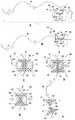
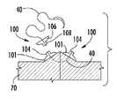
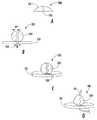
도 1의 A 내지 E는 본 발명에 따른 양방향 고정 기구(100)의 예시적 실시형태를 도시한다. 양방향 고정 기구는 제시된 터널, 채널, 또는 그루브(즉, 제 1 개구(103) 및 제 2 개구(107))의 가장 중심의 점에 의해 한정되는 바와 같은 종축선을 따라 반대 방향으로 배향된 2 개의 별개의 고정 기구로 구성된다. 도시된 바와 같이, 고정 기구(100)의 좌측 부분은 피가공물에의 적용을 위한 제 1 접촉면(102)을 갖는 제 1 접촉 부품(101) 및 선형 요소를 수납하기 위한 제 1 개구(103)를 포함한다. 고정 기구(100)의 좌측 부분은 또한 제 1 접촉면(102)의 반대측의 제 1 접촉 부품(101)의 일측면 상에 선형 요소의 일부를 고착하기 위한 제 1 고정 부품(104)을 포함한다.Figures 1A-E illustrate an exemplary embodiment of a
고정 기구(100)의 우측 부분은 피가공물에의 적용을 위한 제 2 접촉면(106)을 갖는 제 2 접촉 부품(105) 및 선형 요소를 수납하기 위한 제 2 개구(107)를 포함한다. 고정 기구(100)의 우측 부분은 또한 제 2 접촉면(106)의 반대측의 제 2 접촉 부품(105)의 일측면 상에 선형 요소의 일부를 고착하기 위한 제 2 고정 부품(108)을 포함한다.The right portion of the
도시된 바와 같이, 고정 기구의 좌측과 우측 부분은 중간 접합부(109)에서 물리적으로 연결된다. 더욱이, 제 1 접촉 부품(101)과 1 고정 부품(104)은 물리적으로 연결된다. 제 2 접촉 부품(105)과 제 2 고정 부품(108)도 물리적으로 연결된다. 그렇다 해도, 이들 부분 및 부품의 각각은 상호로부터 물리적으로 분리될 수 있다.As shown, the left and right portions of the anchoring mechanism are physically connected at the
도 1의 B는 도 1의 C 및 D에 도시된 채널 또는 그루브가 아니라 폐쇄된 터널을 형성하는 제 1 개구(103) 및 제 2 개구(107)를 갖는 고정 기구(100)의 예시적 실시형태를 도시한다.1B illustrates an exemplary embodiment of a
도시된 바와 같이, 복합 기구(100)은 대칭적 개별의 고정 부품을 갖지만, 다른 예시적 기구는 비대칭적 부품을 포함할 수 있다. 더욱이, 2 개의 부품 고정 기구는 물리적으로 분리될 수 있거나 단일의 복합 유닛으로서 형성될 수 있다. 2 개의 부품 고정 기구의 각각 내에 선형 요소를 고착하는 작동 시, 부품 고정 기구는 분리될 수 있고, 독립적으로 기능할 수 있다. 이 실시형태에서, 각각의 개별의 부품 고정 기구는 중심(또는 중간) 섹션(예를 들면, 제 1 고정 부품(104) 또는 제 2 고정 부품(108)) 보다 통상적으로 더 넓은 측면(또는 말단) 섹션(즉, 제 1 접촉 부품(101) 또는 제 2 접촉 부품(105))을 명시한다. 중심(또는 중간) 섹션은 사용을 위해 요구되는 정도까지 그루브, 노치, 채널, 또는 터널 내에 선형 요소를 구속하도록 작동될 수 있도록 설계된다. 경우에 따라, 측면 섹션은 구성의 변화 또는 이러한 기능을 촉진하는 다른 변화를 받을 수도 있다. 개별의 (부품) 고정 기구 또는 복합적인 양방향 기구는 단일 재료로 형성될 수 있지만, 다른 경우 중심(중간)과 측면(말단) 섹션이 상이한 재료로 구성될 수 있다.As shown, the
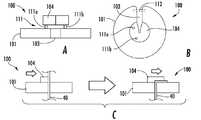
도 2의 A 내지 F는 본 발명에 따른 양방향 고정 기구(100)의 예시적 실시형태를 이용하는 예시적 방법을 도시한다. 도 2의 A 및 B는 양방향 고정 기구(100)가 먼저 선형 요소(40)에 적용될 수 있는 방법을 도시한 것으로서, 여기서는 바늘(41)을 구비한 봉합사의 실시예를 시연하고 있다. 동일한 원리가 강성 또는 코드형의 임의의 선형 요소에 적용될 수 있다. 고정될 선형 요소(40)는 선형 요소(40)의 종축선을 따른 어떤 위치에서 양방향 고정 기구(100)의 공통의 채널, 그루브, 또는 터널 내에 위치된다.Figures 2A-F illustrate an exemplary method of using an exemplary embodiment of a
도 2의 C 내지 D에 도시된 바와 같이, 다음에 양방향 기구(100)는 선형 요소가 고정 기구(100)에 의해 견고하게 유지되도록 작동된다. 이 실시형태에서, 이러한 고정은 적용기 기구(50)를 이용하여 전성이 있는 또는 변형가능한 중심 섹션(예를 들면, 제 1 고정 부품(104), 제 2 고정 부품(108), 및 중간 접합부(109))를 변형시킴으로써, 수용된 선형 요소(40)에 대해 중심 섹션의 채널, 그루브, 또는 터널의 측면을 협착하는 것이다. (도 2의 D 참조). 따라서 적용기 기구(50)는 압착기의 역할을 한다.As shown in FIGS. 2C-D, the
더욱이, 적용기 기구(50)는 이러한 기능을 가능하게 하는 중심(중간) 섹션의 본체에 접촉하는 표면, 작동 후에 양방향 고정 기구(100)를 2 개의 부품 고정 기구로 분할하기 위한 절단 요소(도 2의 E 및 F 참조), 및 기구(100)의 유지, 배향, 또는 배치를 도와주는 표면 특징부(feature)를 포함하는 특수한 특징부를 보여준다. 적용기 기구(50)는 손의 압력, 공압, 전기, 또는 다른 수단에 의해 기계적으로 작동될 수 있다. 또한, 적용기 기구(50)는 단일(부품) 고정 기구, 단일 양방향 고정 기구로서 기능하도록 배향되는 2 개의 물리적으로 분리된 (부품) 고정 기구, 및/또는 양방향 고정 기구를 배치하도록 설계될 수 있다. 또한, 적용기 기구(50)는 각각의 배치 후에 개별적으로 장착되는 새로운 고정 기구를 구비하는 단일-장착 설계이거나 새로운 고정 기구가 적용기 기구(50)에 의해 배치 위치로 전진하는 다중-장착 기구일 수 있다. 적용기 기구(50)는 내시경으로서 설계될 수 있다.Moreover, the
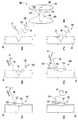
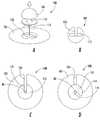
도 3의 A 내지 F는 본 발명에 따른 고정 기구(100)의 다수의 예시적 실시형태 및 그 특징을 도시한다. 고정 기구는 다수의 형상, 재료 조성, 색상, 프로파일, 또는 다른 특징을 가질 수 있다. 중심(중간, 정점) 섹션(즉, 제 1 고정 부품(104), 제 2 고정 부품(108), 및/또는 중간 접합부(109))는 평활한 프로파일 및 또는 예를 들면 도 3의 C 내지 E에 도시된 바와 같이 (예를 들면, 고정을 위한 더 큰 채널 면적을 제공하기 위해) 높은 프로파일(high profile)을 가질 수 있다. 중심 섹션은 단독 및 측면(말단, 접촉) 섹션(즉, 제 1 접촉 부품(101) 및 제 2 접촉 부품(105))과 공동의 양자 모두에서 평활한 외형을 생성하는 (예를 들면, 도 3의 A에 도시된 바와 같은) 더 낮은 프로파일을 가질 수 있다Figures 3A-F illustrate a number of exemplary embodiments and features of a
도 3의 B는 물리적으로 분리된 구조물인 측면(말단, 접촉) 섹션 및 중간(중심, 고정) 섹션을 갖는 고정 기구(100)의 예시적 실시형태를 도시한다. 중심 섹션은 도 3의 B의 상측 부분에 도시된 바와 같이 클립의 형태를 취할 수 있다.Figure 3B shows an exemplary embodiment of a
이 중심 섹션은 배치 전에 비교적 직선의 구성을 가질 수 있고, 또는 고정 기구의 위치결정, 정렬, 고착, 적용, 제거 또는 기능을 도와주기 위한 그루브, 노치, 평평한 표면, 구멍, 텍스처, 팽출부 또는 다른 표면 특징부를 보일 수 있다. 유사하게, 측면(말단, 접촉) 섹션은 고정 기구의 위치결정, 정렬, 고착, 적용, 제거 또는 기능을 도와 주기 위한 구멍, 노치, 그루브, 텍스처, 평평한 표면, 또는 다른 표면 특징부와 같은 외형 변화를 보일 수 있다. 예를 들면, 도 3의 E는 고정 기구와 피가공물 사이의 계면을 향상시키기 위해 컵 형상의 외형을 갖는 접촉면(102)을 포함하는 예시적 고정 기구(100)를 도시한다. 도 3의 F는 적용기 기구(50) 내에 고정 기구(100)의 정렬을 촉진하는 평평한 측면을 갖는 예시적 고정 부품의 부감도를 도시한다. 이와 같은 특징부는 적용기 기구에 의해 제시되는 외형과 상호작용할 수 있고, 또는 배치 전, 배치 중, 또는 배치 후에 고정 기구가 접촉되는 표면의 특징부를 수용할 수 있다.This central section may have a relatively straight configuration prior to placement or may include a groove, notch, flat surface, hole, texture, bulge, or other surface to assist in positioning, aligning, Surface features can be seen. Similarly, the side (distal, contact) sections may be configured to have a contour change such as a hole, notch, groove, texture, flat surface, or other surface features to assist in positioning, aligning, . ≪ / RTI > For example, FIG. 3E illustrates an
도 4의 A 내지 C는 본 발명에 따른 고정 기구(100)의 예시적 실시형태 및 적용기 기구(50)의 예시적 실시형태를 사용하는 예시적 방법을 도시한다. 도시된 바와 같이, 중심 섹션(예를 들면, 제 1 고정 부품(104), 제 2 고정 부품(108), 및 중간 접합부(109))의 변형은 부품 (단일) 고정 기구 또는 양방향 기구의 종축선에 대해 약 90도의 중심 섹션의 굴곡 운동에 의해 발생한다. 굴곡은 또한 선형 요소(40)를 수용하고 있는 터널, 그루브, 또는 노치를 협착하도록 중심 섹션을 압착하고, 기구의 높이를 감소시키기 위해 측면(접촉, 말단) 섹션(즉, 제 1 접촉 부품(101) 또는 제 2 접촉 부품(105))에 접촉하도록 변형된 중심 섹션을 위치시킬 수 있다. 예를 들면, 도 5의 C 내지 F를 참조할 것. 또한, 이 실시형태에서의 측면 섹션은 변형된 중심 섹션을 수용하기 위한 그루브, 노치, 또는 함몰부를 나타낼 수 있다. 예를 들면, 도 5의 C 내지 F를 참조할 것. 중심 섹션은 굴곡 각도가 최대의 예각인 천이 구역에 구멍, 윈도우, 또는 그루브(즉, 접근 개구(110))가 제공됨으로써 수용된 선형 요소에의 접근을 제공하도록 구성될 수 있다. 예를 들면, 도 5의 C 내지 F를 참조할 것. 접근 개구(110)는 측면 섹션으로부터 중심 섹션의 제거 없이 수용된 선형 요소(40)의 분할을 가능하게 한다. 열의 적용, 집적된 또는 도포된 접착제(예를 들면, 압력 감수성 접착제, 시아노아크릴레이트 등), 광 활성, 기계적 활성(예를 들면, 초음파 에너지), 핀, 쐐기, 나사, 포스트, 상호연결 부품 또는 다른 수단을 포함하는 고정 기구(100) 내에 선형 요소(40)의 고정을 촉진시키기 위한 다른 고정 수단이 사용될 수 있다. 중심 섹션은 고유의 접착제 특성을 갖는 재료로 구성될 수 있다.Figures 4A-C illustrate an exemplary method of using the exemplary embodiment of the
도 5의 A 내지 도 6은 본 발명에 따른 고정 기구(100)의 다수의 예시적 실시형태 및 그 특징부를 도시한다. 도 5의 A에 도시된 바와 같이, 중심 섹션(예를 들면, 제 1 고정 부품(104))과 측면 섹션(예를 들면, 제 1 접촉 부품(101))은 (중심 채널, 터널, 또는 그루브에 의해 한정되는 종축선에 관련하여) 중심 섹션 및 측면 섹션의 양자 모두보다 작은 폭인 천이 구역(111)에서 연결되도록 설계될 수 있다. 천이 구역(111)은 적용기, 보관 용기, 적용기-장착 기구, 또는 다른 기구 내에 고정 기구(100)를 위치결정 및/또는 고착시키는 것을 촉진한다. 천이 구역(111)은 또한 피가공물로부터 고정 기구(100)의 제거에서와 같이 중심 섹션과 측면 섹션의 분리가 요망되는 경우에 이러한 분리를 촉진시킬 수 있다.Figures 5A-6 illustrate a number of exemplary embodiments and features of the
도 6에 도시된 바와 같이, 중심 채널, 그루브, 또는 터널은 고정 기구(100) 내에 선형 요소(40)를 고정하는 것을 돕기 위한 스트리에이션(striation), 횡단 그루브, 텍스처, 접착제, 파형, 또는 다른 특징을 나타낼 수 있다. 이러한 특징은 측면 섹션, 중심 섹션 또는 양자 모두의 섹션에 한정될 수 있다.6, a center channel, a groove, or a tunnel may be used as a striation, a transverse groove, a texture, an adhesive, a wave form, or other to assist in securing the
측면 섹션은 도 5의 D 및 E에 도시된 바와 같이 배치 중에 중심 섹션을 수용하도록 구성될 수 있다. 또한, 측면 섹션에서의 수용 특징부의 치수는 중심 섹션의 폭보다 작은 폭을 갖도록 구성될 수 있고, 그 결과 중심 섹션이 도 5의 F에 도시된 바와 같이 측면 섹션의 수용 특징부 내에 위치되었을 때 중심 섹션을 압박하는 압축력을 제공한다.The side sections may be configured to accommodate the center section during deployment, as shown in Figures 5 and 5, The dimension of the receiving feature in the side section may also be configured to have a width less than the width of the center section such that when the center section is positioned within the receiving feature of the side section as shown in Figure 5 F, Providing a compressive force to compress the section.
측면(말단, 접촉) 섹션(즉, 제 1 접촉 부품 또는 제 2 접촉 부품)의 접촉면, 통상적으로 중심 섹션의 반대측 표면은 접착제, 의약품, 패딩, 흡수성 재료, 또는 사용을 증진시키기 위한 다른 특징을 나타낼 수 있다. 예를 들면, 접촉면 상에 실리콘 코팅이 있으면, 선형 요소가 봉합사인 경우, 고정 기구가 피부 또는 조직과 접촉할 때 고정 기구의 기능을 향상시킬 수 있다. 유사하게 중심(중간) 섹션은 슬롯, 그루브, 노치, 및/또는 표면 특징부와 같은 특징부를 제시할 수 있고, 이것은 고정 기구를 고착, 배치, 또는 제거하는 것을 도와주는 기능을 하거나, 또는 (예를 들면, 고정 기구에 추가의 구조물을 고착하기 위한) 이차 고정점으로서 사용될 수 있다.The contact surface of the side (distal, contact) section (i.e., the first or second contact component), typically the opposite side of the center section, exhibits adhesives, medicines, padding, absorbent materials, or other features for promoting use . For example, a silicone coating on the contact surface can improve the function of the fixture when the fixture is in contact with the skin or tissue, if the linear element is a suture. Similarly, the center (middle) section may present features such as slots, grooves, notches, and / or surface features, which serve to help secure, fix, or remove the fixture, For example, for securing an additional structure to a fixture).
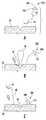
도 7의 A 내지 E는 본 발명에 따른 고정 기구(100)의 예시적 실시형태 및 제거 공구(60)의 예시적 실시형태를 사용하는 예시적 방법을 도시한다. 도 7의 A는 고정 부품(104)과 접촉 부품(101) 사이에서 제거 공구(60)가 슬라이딩할 수 있도록 변형하는 가요성 고정 부품(104)을 포함하는 고정 기구(100)를 도시한다. 도 7의 B는 고정 부품(104)과 접촉 부품(101) 사이에서 제거 공구(60)가 슬라이딩할 수 있도록 고정 부품(104)과 접촉 부품(101) 사이의 좁은 천이 구역(111)을 갖는 고정 기구(100)를 도시한다.7A-7E illustrate an exemplary embodiment of a
도 7의 C는 접촉 부품(101), 고정 부품(102), 및 좁은 천이 구역(111)을 갖는 2 개의 고정 기구(100)에 의해 피가공물(70)(예를 들면, 환자의 피부)에 고착되는 선형 요소(40)를 도시한다. 제거 공구(60)는 고정 기구(100) 중 하나 상에 위치된다. 도 7의 D에서, 제거 공구는 천이 구역(111) 및 선형 요소(40)를 맞물려 절단하고, 이것에 의해 접촉 부품(101)으로부터 고정 부품(102)을 단절시킨다. 더욱이, 도 7의 D의 선형 요소(40)는 우측 상의 고정 기구(100)에만 고착된다. 도 7의 E는 피가공물(70)로부터 선형 요소(40)와 함께 우측 상의 고정 기구(100)의 제거 및 피가공물(70)로부터 접촉 부품(101)의 제거를 도시한다.7C shows a state where the workpiece 70 (e.g., the patient's skin) is contacted by the two fixing
일단 배치되면(즉, 피가공물에 고착되면), 고정 기구(100)는 중심(고정) 섹션의 해제, 측면(접촉) 섹션으로부터 중심 섹션의 분리, 굴곡펴기, 비틀림펴기, 또는 측면 섹션으로부터 중심 섹션을 나사돌려빼기, 핀 또는 다른 고정 구조물의 재위치결정, 핀 또는 다른 고정 구조물의 재위치결정, 선형 요소 고정의 구역과 측면 섹션의 접촉면 사이의 일점에서 선형 요소의 분할, 또는 측면 섹션의 접촉면과 이것이 접합하는 표면 사이의 일점에서 선형 요소의 분할을 포함하는 다양한 방법에 의해 제거될 수 있다. 선형 요소는 중심 섹션을 제거함으로써 해제될 수 있다. 중심 섹션의 해제 제거는 중심 섹션과 측면 섹션(즉, 천이 구역) 사이의 부착의 수, 크기 및 위치에 따라 부분적 또는 전체적일 수 있다. 예를 들면, 중심 섹션이 2 개 이상의 물리적으로 분리된 섹션이고, 제거력이 중심 섹션의 하나의 부품과 측면 섹션 사이의 부착을 분할하는 경우, 중심 섹션의 부분(들)은 선형 요소가 해제될 때 무손상(intact)을 유지할 수 있다.Once secured (i.e., secured to the workpiece), the
측면 섹션으로부터 중심 섹션의 제거는 또한 중심 섹션과 측면 섹션 사이의 일점(즉, 천이 구역)에서 선형 요소의 분할을 포함할 수 있고, 따라서 중심 섹션과 동시에 선형 요소를 해제한다.Removal of the center section from the side section may also involve the division of the linear element at one point (i.e., the transition area) between the center section and the side section, thus releasing the linear element at the same time as the center section.
다른 예시적 실시형태에서, 중심 섹션 또는 천이 구역은 선형 요소에 접근할 수 있는, 그리고 측면 섹션으로부터 중심 섹션을 제거함이 없이 천이 구역 내에서 선형 요소의 전달을 허용하는 구멍, 윈도우, 그루브 또는 다른 특징부를 포함할 수 있다. 선형 요소는 고정 기구와 효율적으로 상호작용하도록, 그리고 고정 기구 상에 위치되도록 특수하게 설계되는 가위, 칼, 외과용 메스, 또는 특수 절단 기구를 사용하여 절단될 수 있다. 또한, 측면 섹션으로부터 중심 섹션을 분리하기 위한 기구의 실시형태는 천이 구역에서 측면 섹션으로부터 분리 시에 분할된 중심 섹션이 포획되는 체임버 또는 공간을 포함할 수 있다.In other exemplary embodiments, the central section or transition region may have a hole, window, groove or other feature that allows access to the linear element and allows the transfer of the linear element within the transition region without removing the center section from the side section Section. The linear element may be cut using scissors, knives, surgical scalpels, or special cutting tools that are specifically designed to interact with the fixture and be located on the fixture. Embodiments of the mechanism for separating the central section from the side section may also include a chamber or space in which the divided central section is captured when detached from the side section in the transition section.
도 7의 A 내지 E는 배치되었을 때 중심 섹션과 측면 섹션의 전체의 복합 형상이 평활하고 낮은 프로파일의 외형을 취하는 고정 기구의 실시형태를 보여준다. 이와 같은 외형은 외력이 고정 기구 상에 작용하거나 고정 기구를 변위시킬 가능성을 감소시키는 것과 같은 고정 기구에 잠재적인 이점을 제공한다. 일예로서, 만일 고정 기구가 피부를 통해 봉합사를 고정하기 위해 사용되는 수술용 버튼(button)의 형태라면, 이와 같은 낮은 프로파일은 기구가 타격을 받거나, 마찰되거나 또는 충돌됨으로써 고정 기구를 일시적으로 변위시켜 환자의 통증을 유발하거나 또는 치유 중의 창상에 위해를 가할 수 있는 가능성을 감소시킨다.7A to 7E show an embodiment of a locking mechanism in which the overall complex shape of the central section and the side sections when placed is smooth and takes a low profile profile. Such contours provide a potential benefit to the stationary mechanism, such as reducing the possibility of external forces acting on the stationary mechanism or displacing the stationary mechanism. As an example, if the fixture is in the form of a surgical button used to secure the suture through the skin, such a low profile may cause the fixture to be temporarily displaced as the fixture is struck, rubbed or impacted Thereby reducing the likelihood of causing a patient ' s pain or injuring a wound during healing.
또 하나의 추가의 사용 방법에서, 만일 선형 요소가 흡수성 수술용 봉합사 재료라면, 봉합사 분해의 자연적 프로세스, 예를 들면, 가수분해는 사용자의 개입 없이 진행된다. 봉합사가 구조적 통합성을 유지하기에 충분한 인장 강도를 결여하는 시점에서, 양자 모두의 고정 기구는 해제되어 자발적으로 탈락할 수 있고, 또는 조직 표면으로부터 닦여질 가능성이 있으므로 임의의 특별한 봉합사 또는 고정 기구의 제거의 필요성이 배제될 수 있다.In yet another method of use, if the linear element is an absorbable surgical suture material, the natural process of suture dissolution, e.g., hydrolysis, proceeds without user intervention. At the point where the suture lacks sufficient tensile strength to maintain structural integrity, both locking mechanisms may be released and fall off spontaneously or may be wiped from the tissue surface, so that any special suture or fixation device The need for removal can be ruled out.
도 8의 A 내지 도 10은 본 발명에 따른 고정 기구(100)의 예시적 실시형태를 사용하는 예시적 방법을 도시한다. 양방향 고정 기구(100)를 사용하면, 양방향 고정 기구의 배치가 첫번째의 2 부분의 선형 요소 기능 중 제 2 부분을 동시에 완료하고, 선형 요소 상에 적절히 배향된 단일 부품의 고정 기구를 사전에 장착함으로써 두번째의 2 부분의 선형 고정 기능 중 제 1 부분을 완료하는 사이클이 형성된다.Figures 8A-10 illustrate an exemplary method of using an exemplary embodiment of a
도 8의 A 및 도 10은 예시적 목적을 위한 수술용 봉합사의 배치를 도시한 것이지만 본 방법 및 기구 기능의 원리는 강성 또는 코드형 선형 요소를 갖는 다른 양방향 고정 기구에 적용할 수 있다. 도 8의 A에 도시된 사이클의 출발 시, 접촉 부품(101) 및 고정 부품(104)을 포함하는 부품 고정 기구(100)는 봉합사(40)의 자유 단부에 부착된다. 고정 기구(100)는 접촉 부품의 접촉면(102), 즉 고정 부품(104)의 반대쪽 표면이 중심 섹션(즉, 고정 부품(104))보다 봉합 바늘(41)에 더 근접하도록 배향된다. 바늘(41)은 창상 주변을 접근시키기 위해 통상적으로 실행되는 바와 같이 조직을 통과시킨다. 도 8의 A 내지 C를 참조할 것. 바늘(41)이 조직으로부터 노출되고, 봉합사(40)(즉, 선형 요소)가 전진될 때, 제 1 고정 기구(100)의 측면 섹션(즉, 접촉 부품(101))의 접촉면은 피부와 접촉 상태로 되고, 봉합사 상에 미치는 추가의 장력에 의해 창상의 주변은 적절한 정렬 상태가 된다. 도 9의 A를 참조할 것. 이러한 장력 및 접근화가 유지되는 상태에서, 이미 부착된 부품 고정 기구의 반대측의 결함 측 상의 조직으로부터 노출되는 봉합사(40)가 양방향 고정 기구(100)의 중심 채널, 그루브, 또는 슬롯 내에 위치하도록 양방향 고정 기구(100)가 위치된다. 양방향 고정 기구(100) 내의 봉합사(40)의 이러한 위치가 유지되는 중에, 양방향 고정 기구(100)의 하나의 부품의 측면 섹션(즉, 접촉 부품(101))의 접촉면(102)은 조직의 제 2 표면에 접촉하게 된다. 도 9의 B를 참조할 것.Figures 8A and 10 illustrate the placement of a surgical suture for illustrative purposes, but the principles of the present method and instrumental function are applicable to other bi-directional anchoring devices having rigid or corded linear elements. At the start of the cycle shown in FIG. 8A, the
양방향 고정 기구(100)를 파지하고 정렬하기 위해 사용될 수 있는 적용기는 제 1 고정 부품(105) 및 제 2 고정 부품(108) 내에 봉합사(40)를 고정하도록 작동된다. 또한 적용기의 작동에 의해 제 2 고정 부품(108)으로부터 제 1 고정 부품(105)이 분리되고, 봉합사(40)가 절단된다. 도 10을 참조할 것.An applicator that can be used to grasp and align the
배치가 완료되면, 창상은 인접한 상태에 유지되고, 분할된 봉합사의 양 단부는 창상의 양 측상의 부품 고정 기구 내에 고착되고, 부품 고정 기구는 사전에 장착되고, 다음 사이클의 개시를 위해 적절히 배향된다. 다시 말하면, 봉합사(40), 바늘(41), 및 도 10에 도시된 고정 기구(100)의 제 2의 분리된 반분(half)은 도 8의 A에 도시된 바와 같은 다른 창상의 접근화를 개시하기 위해 사용될 수 있다.When the placement is completed, the wound surface is held in an adjacent state, both ends of the divided suture are fixed in the component fixture on both sides of the wound, the component fixture is pre-mounted and properly oriented for the start of the next cycle . In other words, the second separate half of the
양방향 고정 기구의 배치가 하나의 2-부분의 고정 기능 중의 제 2 반분 및 제 2의 2-부분의 고정 기능 중의 제 1 반분을 동시에 완료하므로, 고정 기구의 배치는 더 신속하고 더 효율적이 된다. 또한, 선형 요소는 중심 섹션의 정점에 바로 인접하여 분할되므로 선형 요소 길의 낭비가 본질적으로 없고, 그 결과 길이에 관하여 선형 요소의 활용성이 더 커질 수 있다. 일예로서, 수술용 버튼으로서 고정 기구를 사용하면 단일 봉합-바늘의 조합을 이용하여 달성될 수 있는 개별의 창상 접근화의 수가 최대화된다.Since the arrangement of the bi-directional fastening mechanism concurrently completes the first half of the fastening function of the second half of the one two-part fastening function and the fastening function of the second two-part, the arrangement of the fastening mechanism becomes faster and more efficient. In addition, since the linear element is divided immediately adjacent to the apex of the central section, there is essentially no waste of the linear element length, and as a result the utility of the linear element with respect to length can be greater. As an example, the use of a locking mechanism as a surgical button maximizes the number of individual wound accesses that can be achieved using a single suture-needle combination.
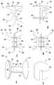
도 11의 A는 예시적 고정 기구(100)의 측면도를 도시하고, 도 11의 B는 동일한 예시적 고정 기구(100)의 부감도를 도시한다. 고정 기구(100)는 개구(103)와 고정 부품(104)을 갖는 접촉 부품(101)을 포함한다. 고정 기구(100)는 또한 접촉 부품(101)과 고정 부품(104)을 접합하는 천이 구역(111)을 포함한다. 도시된 천이 구역(111)은 접촉 부품(101)과 고정 부품(104)을 연결하는 포스트(post) 또는 로드를 포함한다.Fig. 11A shows a side view of an
본 발명에 따른 고정 기구의 예시적 실시형태는 세장형이거나, 격벽을 갖거나, 또는 불연속인 천이 구역에 의해 측면(접촉, 말단) 섹션에 연결되는 중심(중간) 섹션을 포함할 수 있다. 예를 들면, 천이 구역은 측면 섹션과 중심 섹션 사이의 거리를 증가시키기 위한 "스페이서"로서의 기능 및 기구의 기능을 촉진시키는 기능의 양자 모두의 기능이 가능한 중심 섹션을 측면 섹션에 연결하는 포스트 또는 로드의 형태를 나타낼 수 있다.An exemplary embodiment of a fixture according to the present invention can include a central (middle) section that is connected to a side (contact, end) section by a transition zone that is elongated, has a partition, or is discontinuous. For example, the transition zone may be a post or rod connecting the center section to a side section that is capable of functioning as both a "spacer" for increasing the distance between the side section and the center section, Can be expressed.
도 11의 B는 고정 기구(100)의 공통의 채널, 그루브, 또는 슬롯에 대해 옵세트된 천이 구역 연결부(111a, 111b)를 도시한다. 천이 구역 연결부(111a, 111b)에 의해 측면 섹션(즉, 접촉 부품(101))에 부착되는 중심 섹션(즉, 고정 부품(104))의 부분은 변형을 유발하는 배치력의 적용 중에 안정하게 유지되고, 접촉 부품(101)에 부착되지 않은 고정 부품(104)의 부분은 공통의 채널, 그루브, 또는 슬롯에 대해 이동할 수 있다.FIG. 11B shows transition zone connections 111a and 111b that are offset relative to a common channel, groove, or slot of the
도 11의 B의 예시적 실시형태는 접촉 부품(101)의 다른 부분 상의 구멍, 슬롯, 그루브, 또는 다른 표면 특징부와 연결되는 포스트, 핀, 로드, 또는 다른 표면 특징부(예를 들면, 고정용 핀(112))을 갖는 접촉 부품(101)을 포함하므로, 특징부가 접근될 때 접촉 부품(101)을 상호연결, 연결, 또는 고착시킨다. 측면 섹션(즉, 접촉 부품(101))과 중심 섹션(즉, 고정 부품(104)) 사이의 부착을 변경함으로써, 중심 섹션은 또한 측면 섹션에 대해 회전 또는 선회될 수 있고, 따라서 고정 기구에 선형 요소를 고착시킬 수 있다.The exemplary embodiment of FIG. 11B may include a post, pin, rod, or other surface feature (e. G., Fixed (not shown)) that is connected to a hole, slot, groove, or other surface feature on another portion of the contact component < (E.g., pins 112 for use), so that the
도 12의 A 내지 12의 D는 본 발명에 따른 예시적 고정 기구(100) 및 예시적 적용기 기구(50)를 사용하는 예시적 방법을 도시한다. 단일 부품의 고정 기구, 동시에 적용되는 2 개의 물리적으로 분리된 부품의 고정 기구, 또는 양방향 고정 기구는 특수하게 설계된 배치 공구(예를 들면, 적용기 기구)와 결합되기 위한 형상 특성을 나타낼 수 있다. 이와 같은 표면 특징부는 평평한 표면, 슬롯, 그루브, 노치, 베벨, 또는 다른 형태를 포함할 수 있고, 측면 섹션의 접촉면 또는 본체 상, 측면 섹션과 중심 섹션 사이의 천이 구역, 중심 섹션의 본체 내, 또는 양방향 기구의 경우에 2 개의 중심 섹션 사이의 접합부에 존재할 수 있다.Figures 12A-12D illustrate an exemplary method of using the
도 12의 A 내지 D는 예시적 표면 특징부를 도시한다. 도 12의 A는 도 12의 A의 좌측에 도시된 A, B 및 C의 위치에서 접촉 부품의 단면을 고정 기구의 단면에 비교하는 단면도 A, B 및 C를 포함한다. 단면 A에서 도시된 바와 같이, 접촉 부품의 단면은 원형이고, 개구(103)가 삽입되어 있다. 단면 B에서 도시된 바와 같이, 천이 구역(111)은 적용기 기구(50)를 수납하기 위한 개구(103)에 평행한 평평한 표면을 포함하는 단면을 갖는다. 도 12의 B를 참조할 것. 단면 C에 도시된 바와 같이, 중간 접합부(109)는 접촉 부품의 단면보다 작은 원형의 단면을 갖는다. 예시적 표면 특징부는 양방향 고정 기구의 중심 섹션과 측면 섹션 사이의 천이 구역 상에 평평한 표면을 포함한다.Figures 12A-D illustrate exemplary surface features. Fig. 12A includes cross-sectional views A, B and C for comparing the cross-section of the contact part to the cross-section of the fixture mechanism at the locations of A, B and C shown on the left side of Fig. As shown in section A, the cross-section of the contact part is circular and an
예시적 적용기 기구(50)는 평면의 위쪽으로부터 보았을 때, 천이 구역(111) 내에서 그리고 천이 구역(111)의 주위에서 전진될 수 있도록 크기, 형상 및 배향의 평행한 평평한 연부를 갖는 형상을 갖는 본질적으로 평평한 부품인 적용기 가이드(51)를 포함한다. 이 예시적 실시형태에서, 적용기 기구(50)는 2 개의 이와 같은 적용기 가이드를 포함하고, 그리고 적용기 공구가 양방향 고정 기구(100) 상에서 진행될 때, 각각의 적용기 가이드는 복합 양방향 고정 기구(100)의 각각의 부품 고정 기구의 천이 구역(111)과 서로 맞물린다. 적용기 기구(50)는 또한 2 개의 적용기 가이드(도 12의 B 및 C의 상부 부분을 참조할 것) 사이에 위치하는 2 개의 압착기 암(52)을 제시하고, 적용기 가이드(51)에 의해 한정되는 2 개의 평면에 평행한 평면을 통과한다.The
적용기 기구(50)가 양방향 고정 기구(100) 상에서 전진될 때, 고정 기구(100)는 선형 요소에 대해 용이하게 위치될 수 있도록 공통의 그루브, 슬롯, 또는 채널이 적용기 기구(50)에 의해 방해받지 않는 상태로 적용기 기구(50)에 대해 일치되는 배향으로 유지된다. 압착기 암(52)(또는 다른 중심 섹션 작동 메커니즘)은 배치를 위해 적절하게 위치 및 고착된다. 압착기 암(52)이 작동될 때, 중심 섹션이 변형되고, 선형 요소는 제 1 고정 부품(104) 및 제 2 고정 부품(108) 내에 고착된다. 압착기 암(52)은 또한 고정 기구(100) 및/또는 선형 요소의 2 개의 반분을 분리하는 절단 요소를 포함할 수 있다. 또한, 천이 구역(111)의 형상 및 적용기 가이드(51) 또는 압착기 암(52)의 형상은 압착기 암(52)이 작동될 때 중심 섹션을 변형시키도록, 그리고 천이 구역(111)의 일부의 길이가 증가되고, 그 결과 천이 구역(111)으로부터 적용기 가이드(51)의 해제가 촉진되도록 설계된다.When the
도 13의 A 내지 G는 본 발명에 따른 예시적 고정 기구(100)를 사용하는 예시적 방법을 도시한다. 도 13의 A에 도시된 바와 같이, 예시적 양방향 고정 기구(100)는 더 좁은 천이 구역을 구비함이 없이 접촉 부품과 고정 부품 사이에 평활한 천이부를 포함한다. 도시된 바와 같이, 고정 기구는 이 고정 기구(100)의 종방향 길이를 통과하는 채널 내에 선형 요소(40)를 수납한다. 도 13의 A 내지 G는 도 8의 A 내지 도 10에 도시된 것과 유사한 고정 기구(100)를 사용하는 방법을 도시한다. 고정 기구(100)의 상부 부분 및 하부 부분은 (예를 들면, 기계적인 힘을 사용하는) 변형 및/또는 열에 의해 분리될 수 있다. 선형 요소(40)는 이와 같은 분리, 접착제에 의해, 또는 다른 메커니즘에 의해 고정 기구(100) 내에 고착될 수 있다.13A-13G illustrate an exemplary method of using an
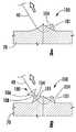
도 14의 A 내지 E는 본 발명에 따른 고정 기구(100)의 예시적 실시형태 및 적용기 기구(50)의 예시적 실시형태를 사용하는 예시적 방법을 도시한다. 부품 고정 기구 또는 양방향 고정 기구의 중심 섹션과 측면 섹션(즉, 고정 부품(104, 108)과 접촉 부품(101, 105)) 사이의 천이 구역(111)은 고정 기구(100)의 적용 및 제거의 양자 모두 중에 이점을 제공할 수 있다. 이 실시형태에서, 적용기 기구(50)는 압착기 암(52)을 포함한다. 고정 기구(100)와 접촉하는 압착기 암(52)의 표면은 압착을 위한 평평한 표면 및 제 2 고정 부품(104, 108) 사이에서 양방향 고정 기구(100) 및 선형 요소(40)의 분할을 위한 융기된 특징부를 포함한다. 적용기 기구(50)의 압착 표면과 중심 섹션(즉, 제 2 고정 부품(104, 108))의 맞물림은 고정 기구(100)와 선형 요소(40)를 안정화 및 고정시키고, 한편 적용기 기구(50)의 절단 표면은 중간 접합부(109)와 맞물려서 중간 접합부(109)를 절단한다.14A-14E illustrate an exemplary method of using an exemplary embodiment of the
도 14의 A에 도시된 바와 같이, 고정 기구(100)는 제 1 접촉면(102) 및 제 1 개구(103)를 갖는 제 1 접촉 부품(101) 및 제 1 고정 부품(104)를 포함한다. 고정 기구(100)는 또한 제 2 접촉면 및 제 2 개구를 갖는 제 2 접촉 부품(105) 및 제 2 개구를 포함한다. 제 1 고정 부품(104)와 제 2 고정 부품(108)은 고정 부품보다 좁은 중간 접합부(109)에서 접합된다. 고정 부품(104, 108)은 고정 부품보다 좁은 천이 구역(111)에 의해 각각의 접촉 부품(101 또는 105)에 접합된다.14A, the
선형 요소(40)는 도 14의 A에 도시된 바와 같이 고정 기구의 개구 내에 설치될 수 있다. 선형 요소(40)의 일단부는 도 14의 B에 도시된 바와 같이 피가공물(70)을 통과할 수 있고, 도 14의 C에 도시된 바와 같이 다른 고정 기구(100)에 의해 고착될 수 있다 적용기 기구(50)는 도 14의 C에 도시된 바와 같이 선형 요소(40)에 장력이 가해지는 동안에 고정 기구(100) 상에 위치된다. 적용기 기구는 선형 요소(40)의 주위의 고정 부품(104, 108)을 압착함으로써 중간 접합부(109) 및 선형 요소(40)를 절단하도록 도 14의 D에 도시된 바와 같이 압착하는 힘에 의해 더욱 작동된다. 도 14의 E는 고정 기구의 분리된 섹션을 제거하는 것을 도시한다.The
도 15의 A 내지 D는 본 발명에 따른 예시적 고정 기구(100) 및 예시적 제거 공구(60)를 사용하는 예시적 방법을 도시한다. 선형 요소(40)의 고정이 중심 섹션(즉, 고정 부품(104))에 제한되고, 측면 섹션(즉, 접촉 부품(101))은 선형 요소(40)를 억제하거나 구속하지 않는 경우, 중심 섹션의 분리는 고정 기구(100)로부터 선형 요소(40)의 해제를 촉진시킬 수 있다. 중심 섹션 및 측면 섹션의 분리 후 중심 섹션이 무손상 상태로 유지되는 예시적인 실시형태에서, 통상적으로 선형 요소도 분할되어야 한다. 측면 섹션으로부터 중심 섹션의 완전 분리 또는 부분 분리가 선형 요소를 해제시키는 (즉, 중심 섹션은 배치된 배향에 유지되지 않는) 실시형태에서, 해제된 중심 섹션은 제거될 수 있고, 선형 요소의 고정은 선형 요소의 분할 없이 해제될 수 있다.Figures 15A-D illustrate an exemplary method of using an
고정 기구의 제거는 제거 공구에 의해 보조를 받을 수 있다. 제거 공구는 다수의 형태를 취할 수 있다. 도 15의 A 내지 D는 접근되는 2 개의 암(61)을 갖는 예시적 제거 공구(60)를 도시하고, 이 접근력은 측면 섹션으로부터 중심 섹션을 분리시킨다. 암(61) 사이의 공간은 분리된 중심 섹션 부품이 수용되도록 수집 체임버를 포함할 수 있다.Removal of the fixture can be assisted by a removal tool. The removal tool can take many forms. 15A-15D illustrate an
다른 실시형태에서, 고정 기구 제거 공구는 일단부에 인접하여 구멍을 구비하는 사각형 박스(도시되지 않음)일 수 있다. 통상적으로 이 구멍은 고정 기구의 중심 섹션을 수용하기에 충분한 크기 및 형상을 갖는다. 통상적으로 사각형 박스는 또한 제거 공구 내의 슬롯을 따라 슬라이딩하여 제거 공구 내의 구멍을 폐쇄하도록 구성된, 제거 공구의 종축선에 평행한 가동식 블레이드를 포함할 수 있다. 실제로, 이와 같은 제거 공구는 고정 기구의 중심 섹션이 제거 공구의 구멍 내에 위치하도록, 그리고 블레이드가 진행될 때, 중심 섹션(및 잠재적으로 수용된 선형 요소)이 측면 섹션으로부터 분리되고, 해제된 중심 섹션이 제거 공구의 박스 내의 공간 내에 지향되도록 위치된다.In another embodiment, the fixture removal tool may be a rectangular box (not shown) having an aperture adjacent one end. Typically the hole has a size and shape sufficient to accommodate the central section of the fixture. Typically, the square box may also include movable blades parallel to the longitudinal axis of the removal tool, configured to slide along the slots in the removal tool to close the holes in the removal tool. In practice, such a removal tool is designed so that the center section of the fixture mechanism is located within the hole of the removal tool, and when the blade is advanced, the center section (and potentially accommodated linear element) Is positioned to be directed in the space within the box of the tool.
도 16의 A 내지 E는 본 발명에 따른 고정 기구(100)의 예시적인 실시형태를 도시한다. 도 16의 B 내지 C는 양방향 고정 기구(100)의 양단부 상의 제 2 접촉 부품(101, 105)의 접촉면(102, 106)을 도시한다. 점선에 의해 도시된 바와 같이, 접촉면(102)의 연부는 고정 기구(100)의 위치를 용이화하도록 제거될 수 있다.16A to 16E show an exemplary embodiment of the
도 16의 D는 고정 부품(104, 108) 내의 2 개의 접근 개구(110)를 포함하는 고정 기구(100)를 도시한다. 접근 개구(110)는 고정 기구의 채널 내의 선형 요소에의 접근을 제공한다. 고정 기구(100)가 피가공물에 고착된 경우, 선형 요소는 선형 요소 상의 장력을 증가시키지 않고 접근 개구(110)를 통해 절단될 수 있다.16D shows the
도 16의 E는 고정 부품(104, 108)보다 좁은 천이 구역(111) 및 중간 접합부(109)를 포함하는 고정 기구(100)를 도시한다. 고정 기구(100)의 이러한 더 좁은 부분은, 예를 들면, 적용기 기구 또는 제거 공구와의 상호작용에 의해 고정 기구(100)의 위치결정 및 선형 요소의 고착을 촉진할 수 있다.Figure 16E shows a
고정 기구의 기능을 향상시키기 위해 고정 기구의 부품, 구역 및 접합부의 구성에 많은 변형이 채용될 수 있다. 예를 들면, 측면 섹션의 주변은 원형의 형상을 취할 수 있고, 배치 또는 위치결정을 촉진하도록 베벨형의 연부를 구비하는 슬롯 또는 그루브를 갖도록 구성될 수 있고, 또는 옵세트되거나, 나선상이거나 비대칭형인 채널 또는 그루브를 가질 수 있다. 양방향 실시형태에서 천이 구역, 중심 섹션, 또는 2 개의 중심 섹션 사이의 연결부에서 유사한 변형이 채용될 수 있다. 중심 섹션 및 연결 섹션은 또한 관통공, 그루브, 또는 구멍을 갖는 튜브로서 형성될 수도 있고, 선형 요소의 고정 강도를 향상시키기 위해 파형 또는 지그-재그 구성을 나타낼 수 있다.Many modifications to the configuration of the components, areas and joints of the fixture can be employed to improve the function of the fixture. For example, the perimeter of the side section can take the shape of a circle and can be configured to have a slot or groove with a beveled edge to facilitate placement or positioning, or can be configured to be offset, spiral or asymmetric Channels or grooves. In a bidirectional embodiment, similar variations may be employed in the transition section, in the central section, or in the connection between the two central sections. The central section and the connection section may also be formed as tubes with through-holes, grooves, or holes and may represent a corrugated or jig-jig configuration to improve the fixing strength of the linear element.
도 17의 A는 접촉 부품(101, 105) 및 고정 부품(104, 108)을 포함하는 고정 기구를 도시한다. 고정 부품(104, 108)은 선형 요소(40)를 고착하기 위해 고정 부품(104, 108) 및/또는 접촉 부품(101, 105) 사이의 선형 요소(40)의 주위에서 폐쇄되는 클립(113)을 포함한다.Fig. 17A shows a fixing mechanism including the
도 17의 B는 자체가 클립인 접촉 부품(101, 105) 및 고정 부품(104, 108)을 포함하는 고정 기구를 도시한다. 따라서, 고정 부품(104, 108)은 접촉 부품(101, 105)에 물리적으로 연결되지 않는다. 고정 부품(104, 108)은 배치 또는 제거를 보조하도록 결합될 수 있는 탭, 폴드(fold), 또는 다른 표면 특징부를 포함할 수도 있다.17B shows a fixing mechanism including the
도 4의 A에 도시된 것과 같은 옵세트된 적용기 공구는 중심 섹션의 압착 외에 폴드 또는 굴곡을 도입함으로써 고정 기구 배치의 메커니즘을 변경할 수 있다. 고정은 중심 섹션 내에 포함된, 또는 적용기 공구의 기능으로서 가해지는 접착제(예를 들면, 압력 감수성 접착제)의 존재에 의해 보조될 수 있다.An off-set applicator tool such as that shown in Fig. 4A can change the mechanism of the fixture arrangement by introducing folds or flexures in addition to squeezing the center section. The fixation may be assisted by the presence of an adhesive (e. G., A pressure sensitive adhesive) contained within the center section or applied as a function of the applicator tool.
도 18의 A는 개구(103)를 갖는 접촉 부품(101)을 포함하는 예시적 고정 기구(100)를 도시한다. 선형 요소는 접촉 부품(101)에 물리적으로 연결되지 않는 고정 부품에 의해 예시적 고정 기구(100) 내에 고착된다.Fig. 18A shows an
도 18의 B 내지 D는 접촉 부품(101) 및 상호연결 고정 부품(104)을 포함하는 예시적 고정 기구(100)를 도시한다. 도 18의 B 및 C에 도시된 사정-장착 상태에서, 고정 부품(104)은 선형 요소를 수납하기 위해 접촉 부품의 개구(103)보다 약간 좁은 개구를 포함한다(즉, W는 W+보다 크다). 사용자가 고정 기구(100) 내에 선형 요소(40)를 설치하고, (예를 들면, 손으로 또는 적용기 기구를 사용하여 개구에 의해 한정되는 고정 기구의 측면들을 함께 가압함으로써) 고정 기구를 작동시킨다. 개구에 의해 한정되는 바와 같은 고정 부품(104)의 양측부는 선형 요소(40)를 견고하게 파지하기 위해 상호연결된다. 고정 부품(104) 또는 접촉 부품(101)은 변형 후에 고정 기구(100)의 고착을 돕기 위한 부속 고정 구조물(예를 들면, 고정용 핀)을 포함할 수 있다.18B to 18D illustrate an
고정 기구는 특수 기능에 부합하는 많은 상이한 프로파일을 구비하도록 구성될 수 있다. 또한, 기구는 제조된 상태(휴지 상태)로부터 "프리-텐션된" 배치 상태로 변형될 수 있고, 이것은 상이한 섹션의 천이 시에, 예를 들면, 나선상으로부터 디스크형 구성으로의 천이 시에 연결 상태로 된다. 도 20의 A 내지 C는 나선 구성으로부터 디스크형 구성으로 천이되는 예시적 고정 기구(100)를 도시한다. 중심 섹션이나 측면 섹션은 기구 기능, 선형 요소의 고착성의 유지, 또는 제거를 보조하도록 결합 또는 상호결합하는 부품을 실증한다.The fixture can be configured to have many different profiles that conform to the special function. The mechanism may also be modified from a manufactured state (dormant state) to a "pre-tensioned" placed state, which may be varied during transitions of different sections, for example, . 20A-20C illustrate an
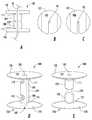
도 19의 A 내지 D는 예시적 고정 기구(100) 및 연결 특징부를 도시한다. 도 19의 A에 도시된 바와 같이, 접촉 부품(101, 105), 천이 구역(111), 고정 부품(104, 108), 및 중간 접합부(109)는 모두 상호연결 요소를 포함한다. 도 19의 B 및 C는 상호 맞물리는 만곡된 표면, 노치, 및 후크를 포함하는 예시적 상호연결 요소의 확대도를 도시한다.Figures 19A-D illustrate an
도 19의 D는 선형 요소(40)에 고착되었을 때 상호연결 요소를 포함하는 다른 예시적 고정 기구(100)를 도시한다. 고정 기구의 상호연결 요소는 고정 기구(100)의 내부의 연결 표면 상에 존재할 수 있고, 및/또는 고정 기구(100)의 외면에 일치되는 외부의 외형을 가질 수 있다. 도 19의 E는 슬롯 또는 후크와 맞물리는 래치 또는 핀을 포함하는 예시적 상호연결 요소를 도시한다. 도 19의 F는 슬롯 또는 후크와 맞물리는 래치 또는 핀을 포함하는 다른 예시적 상호연결 요소를 도시한다.19D shows another
예시적 고정 기구는 배치에 있어서 수용된 선형 요소의 견고한 고정을 보조하기 위해 수납용 채널, 슬롯 또는 그루브 내의 특수 만곡부, 노치, 그루브, 핀, 슬롯, 파형 또는 다른 표면 특징부를 포함할 수 있다. An exemplary fixture mechanism may include special curves, notches, grooves, fins, slots, corrugations or other surface features in the receiving channels, slots or grooves to aid in the rigid fixation of the received linear elements in the arrangement.
도 20의 A 내지 C는 본 발명에 따른 고정 기구(100)의 예시적 실시형태를 도시한다. 고정 기구의 개구(103)는 고정 기구(100)의 기능의 실증을 용이화하도록 고정 기구(100)의 외부 둘레에 비교했을 때 비교적 큰 개구로서 도시되었다. 통상적으로, 개구(103)는 고정 기구(100)의 외부 둘레에 비교했을 때 훨씬 더 작은 둘레를 갖는다.20A to 20C show an exemplary embodiment of the
고정 기구(100)는 측면 섹션(즉, 접촉 부품)이 도 20의 A에서와 같이 휴지 상태(원래의 상태)에서 평평하지 않고, 360 도 회전을 초과하는 나선부를 갖도록 제조될 수 있다. 이 실시형태에서, 공통의 그루브의 경계를 나타내는 측면 섹션의 연부는 기구의 축선에 직각으로 동일한 수평면 내에 위치하지 않는다. 유사하게 중심 섹션의 부분은 고정 기구의 축선과의 관계에서 상이한 수평면 내에 위치한다. 선형 요소-수납용 그루브의 양측면이 도 20의 B에 도시된 바와 같이 기구의 종축선과의 관계에서 유사한 평면이 되도록, 본 기구의 배치는 평면도로부터 측면 섹션의 반경을 증가시키는, 그리고 측면 섹션을 평탄화하는 사전-배치("사전-장착") 변형력의 적용을 포함한다. 이러한 프리텐션력은 측면 섹션의 본체 내에 응력을 부여한다. 그러면 선형 요소는 이제 가시적인 공통의 채널 내에 위치되고, 변형을 유발하는 사전-장착력은 도 20의 C에서와 같이 측면 섹션과 중심 섹션이 상호연결되도록 해제된다. 측면 섹션 상에 부여된 응력이 기구의 배치에 의해 부분적으로만 해제되므로 응력은 중심 섹션을 접근시키는, 그리고 선형 요소를 고착시키는 지속되는 힘을 제공한다. 배치의 반대 순서로 고정 기구가 제거된다. 원래의 "휴지" 상태로부터 사전 배치(프리텐션된) 상태로, 또는 사전 배치(프리텐션된) 상태로부터 배치 상태로, 또는 유사하게 역방향 프로세스(고정 기구 제거)를 돕기 위해 이동을 안내하기 위한 융기부, 그루브, 슬롯, 또는 다른 특징부가 포함될 수 있다.The
도 20의 D 및 E는 도 20의 A 내지 C에 도시된 고정 기구와 동일한 방식으로 기능하는 접촉 부품(101) 및 고정 부품(104)을 포함하는 예시적 고정 기구(100)를 도시한다. 이것에 관련하여, 도 20의 D는 도 20의 B에 대응하는 상태인 예시적 고정 기구(100)를 도시한다. 선형 요소(40)는 도 20의 D에서 볼 수 있는 고정 기구의 개구 내에 설치된다. 그러면 사전-장착력은 고정 기구(100)가 도 20의 E에서와 같이 선형 요소(40)의 주위에 밀착하도록 해제된다.20D and 20E illustrate an
도 21의 A 내지 D는 예시적 고정 기구(100) 및 예시적 적용기 기구(50)를 도시한다. 고정 기구(100)는 접촉면(102) 및 개구(103)를 갖는 접촉 부품(101)을 포함한다. 접촉 부품(101)은 개구(103)를 한정하는 수납용 나사산을 갖는 테이퍼형 벽을 갖는다. 고정 기구(100)은 또한 고정 부품(104)(예를 들면, 중공 나사)을 포함한다. 고정 부품(104)은 채널(114) 및 접촉 부품(101, 105)의 수납용 나사산과 맞물리는 나사산을 포함한다. 도 21의 B에 도시된 바와 같이, 접촉 부품의 테이퍼형 벽 및 고정 부품의 채널(114)은 선형 요소의 배치를 촉진하는 간극을 포함한다.Figs. 21A-D illustrate an
도 21의 C는 고정 기구(100) 및 적용기 기구(50) 내에 장착된 선형 요소(40)를 도시한다. 적용기 기구(50)는 선형 요소(40)에 충돌하거나, 분할하거나, 또는 손상을 주지 않고 선형 요소(40)를 수용하기 위한 슬롯(53)(예를 들면, 슬롯, 그루브, 노치, 구멍, 채널, 스타-드라이브(star-drive))을 포함한다. 적용기 기구(50)의 선단부는 (예를 들면, 도시된 바와 같은 필립스-헤드 나사 인터페이스를 통해) 고정 부품(104)과 맞물림된다. 회전력이 적용기 기구(50)에 가해지는 경우, 고정 부품(104)은 접촉 부품(101) 내로 더 깊게 나사결합된다. 통상적으로, 고정 부품(104)의 적어도 하부 부분은 약간 변형가능한 재료이다. 고정 부품(104)이 접촉 부품(101) 내로 진입될 때, 고정 부품(104)의 적어도 하부 부분은 선형 요소(40)의 주위에 밀착하도록 변형된다(즉, 고정 부품(104)이 압축될 때 채널(114)은 수축된다).Fig. 21C shows the
고정 부품(104)은 2 개 이상의 부분을 가지거나, 회전 운동이 부여될 때 채널(114)이 더 효율적으로 가압(중심을 향해 전진)되도록 슬롯 또는 그루브를 나타낼 수 있다. 고정 부품(104)은 또한 공통의 채널, 슬롯, 또는 그루브의 직경을 비틀어 감소시킬 수 있는 변형가능한 천이 구역 요소를 구비하는 접촉 부품(101, 105)에 연결될 수 있다. 고정 부품(104)은 이 고정 부품(104)이 접촉 부품(101, 105)과의 관계에서 회전되는 경우 접촉 부품(101, 105)과 상호결합하는 포스트, 탭, 또는 다른 특징부를 나타낼 수 있다. 이들 실시형태의 각각에서, 회전력의 반전은 고정된 선형 요소를 해제한다.The
도 22의 A 내지 D는 접촉 부품(101) 및 고정 부품(104)을 포함하는 예시적 고정 기구(100)를 도시한다. 접촉 부품(101)은 개구(103)를 갖는다. 고정 부품(104)의 각각은 채널(114) 및 T자 형상의 포스트(115)를 포함하고, 개구(103)는 특정의 배향에서만 T자 형상의 포스트(115)를 수납하기 위한 형상을 갖는다. 도 22의 C 및 D에서 접촉 부품의 개구(103)는 또한 접촉 부품(101, 105)의 외연부로 연장한다. 도 22의 B는 고정 부품(104)의 저면도를 도시한다.22A to 22D illustrate an
선형 요소는 개구를 통과하여 채널(114) 내로 진입될 수 있다. 도 22의 A에 도시된 바와 같이, 고정 부품(104) 및 그 T자 형상의 포스트(115)는 개구(103)와 정렬되어 개구(103) 내에 삽입된다. 고정 부품(104)은 도 22의 C의 부감도에서 도시된 바와 같이 개구(103) 및 채널(114)과 정렬되도록 접촉 부품(101) 내에서 회전될 수 있다. 그러면 선형 요소(40)는 개구(103) 및 채널(114) 내에 제공될 수 있다. 고정 부품(104)은 도 22의 D에서 도시된 바와 같이 선형 요소(40)를 고착시키도록 접촉 부품(101) 내에서 회전된다. 접촉 부품(101) 및 고정 부품(104)은 고정 부품(104)이 접촉 부품(101, 105) 내에서 회전될 때 선형 요소에 가해지는 힘을 증가시키기 위해 T자 형상의 포스트(115)와 상호작용하는 경사면, 탭, 및/또는 포스트와 같은 추가의 특징부를 구비할 수 있다.The linear element may enter the
도 23의 A 내지 D는 본 발명에 따른 예시적 고정 기구 및 예시적 적용기 기구(50)를 도시한다. 고정 기구(100)는 접촉 부품(101), 고정 부품(104), 및 천이 구역(111)을 포함한다. 천이 구역(111) 및 고정 부품(104)의 양자 모두의 표면 외형은 고정 기구(100)의 배치 및 고정 기구(100)의 제거의 양자 모두를 촉진시킬 수 있다. 이 실시형태에서, 천이 구역(111)은 도 23의 A에서 점선으로 도시된 바와 같이 대향하는 측면 상의 2 개의 평행한 평평한 표면을 갖는다. 고정 부품(104)은 평면도에서 보았을 때 육각형 형상을 갖는다. 접촉 부품(101)으로부터 고정 부품(104)의 분리는 고정 기구(100)의 공통의 채널(114)(예를 들면, 슬롯 또는 그루브)에 의해 한정되는 축선을 중심으로 고정 부품(104)을 선회 또는 비틀기함으로써 달성될 수 있다. 고정 기구(100)의 평평한 표면은 제거 공구로의 역할도 할 수 있는 적용기 기구(50)와 상호작용한다.23A-23D illustrate an exemplary fixture and an
비록 육각형 형상 및 평행한 표면이 설명되었으나, 다른 형상 변화는 본 발명의 범위 내에 포함된다. 예를 들면, 고정 부품(104)은 육각형 형상이 아니라 2 개의 평행한 평평한 표면을 포함할 수 있다. 접촉 부품(101)은 또한 제거를 촉진하는 것을 도와주는 평평한 표면, 구멍, 슬롯, 그루브, 또는 노치와 같은 유사한 외형 특징부를 포함할 수 있다. 또한, 측면 섹션 내의 공통의 슬롯 또는 그루브는 제거 공구와의 안정화의 점(point of stabilization)으로서 기능할 수 있다.Although hexagonal and parallel surfaces have been described, other shape changes are within the scope of the present invention. For example, the
3 개의 섹션(즉, 접촉 부품(101), 천이 구역(111), 및/또는 고정 부품(104)) 중 임의의 2 개는 이와 같은 방식으로 접촉 부품(101)으로부터 고정 부품(104)을 분리시키도록 맞물림될 수 있다. 예를 들면, 이 목적을 위해 적용기 기구(50)는 접촉 부품(101) 및 천이 구역(111), 접촉 부품(101) 및 고정 부품(104), 또는 천이 구역(111) 및 고정 부품(104)과 맞물릴 수 있다.
Any two of the three sections (i.e., the
예시적 실시형태Exemplary embodiments
[1]. 피가가공물 내에서 관통공을 통해 연장하는 선형 요소를 고착하기 위한 고정 기구로서, 상기 고정 기구는,[One]. 1. A fastening mechanism for fastening a linear element in a workpiece extending through a through hole,
a. 일단부 상에 피가공물과 맞물리기 위한 형상의 접촉면을 갖는 베이스 섹션;a. A base section having a contact surface of a shape for engaging the workpiece on the workpiece;
b. 상기 베이스 섹션의 접촉면의 반대측의 정점(중심) 섹션; 및b. A vertex (center) section on the opposite side of the contact surface of the base section; And
c. 선형 요소를 수용하기 위한 형상의 그루브, 슬롯, 채널, 또는 수납용 외형부로서, 상기 베이스 섹션을 통해 최소로 연장하고, 상기 정점 섹션 내로 연장하는, 그루브, 슬롯, 채널, 또는 수납용 외형부를 포함하고;c. A groove, slot, channel, or accommodating contour extending at least through the base section and extending into the apex section for receiving a linear element and;
d. 상기 그루브, 슬롯, 채널, 또는 수납용 외형부는 사전-배치 휴지 상태에서 상기 고정 기구의 종축선을 한정하고;d. The groove, slot, channel, or receiving contour defines a longitudinal axis of the fixture in a pre-positioned rest state;
상기 고정 기구는 변형가능하도록 구성되고, 상기 변형에 의해 상기 그루브, 슬롯, 채널, 또는 수납용 외형부 내의 공간을 수축시키고, 그 결과 변형적 배치 시에 상기 그루브, 슬롯, 채널, 또는 수납용 외형부 내에 위치되는 선형 요소를 고착하고;The fixing mechanism is configured to be deformable and the deformation causes the space in the groove, slot, channel, or accommodating outer contour to be contracted so that the groove, slot, channel, Fix a linear element located within the portion;
상기 선형 요소가 피가공물을 통해 연장하고, 상기 피가공물의 방향으로 힘 벡터가 존재하는 경우, 이렇게 고착된 선형 요소에 가해지는 상기 힘 벡터에 의해 상기 피가공물과 상기 고정 기구가 맞물림되도록 구성된다.
Wherein the linear element extends through the workpiece and, when a force vector is present in the direction of the workpiece, the workpiece and the fixture are engaged by the force vector applied to the linear element thus fixed.
[2]. 피가가공물 내에서 관통공을 통해 연장하는 선형 요소를 고착하기 위한 고정 기구로서, 상기 고정 기구는,[2]. 1. A fastening mechanism for fastening a linear element in a workpiece extending through a through hole,
a. 상기 고정 기구의 변형 후, 일단부 상에 피가공물과 맞물리는 형상의 접촉면을 갖는 베이스 섹션으로서, 휴지 상태에서 상기 기구의 종축선과의 관계에서 중첩하는 표면을 구비하는 평평하지 않은 배향을 갖는, 베이스 섹션;a. A base section having a contact surface shaped to engage a workpiece on one end after deformation of the fixture, the base section having a non-flat orientation with a superimposed surface in relation to the longitudinal axis of the tool in a rest state, section;
b. 상기 접촉 섹션의 접촉면의 반대측의 정점 섹션; 및b. A vertex section on the opposite side of the contact surface of the contact section; And
c. 상기 기구의 부분적인 변형 후, 선형 요소를 수용하기 위한 형상의 그루브, 슬롯, 채널, 또는 수납용 외형부로서, 상기 기구가 부분적으로 변형되는 때에 상기 베이스 섹션 및 정점 섹션의 양자 모두를 통해 연장하는, 그루브, 슬롯, 채널, 또는 수납용 외형부를 포함하고;c. A groove, a slot, a channel, or a receiving contour of a shape for receiving a linear element after partial deformation of the instrument, the contour extending through both the base section and the vertex section when the mechanism is partially deformed , A groove, a slot, a channel, or a receiving contour;
d. 상기 그루브, 슬롯, 채널, 또는 수납용 외형부는 상기 부분적으로 변형된 상태에서 상기 고정 기구의 종축선을 한정하고;d. Wherein the groove, slot, channel, or receiving contour defines a longitudinal axis of the fixture in the partially deformed state;
상기 고정 기구는, 변형의 완료 시 상기 중첩하는 표면이 상기 고정 기구의 종축선과의 관계에서 위치전환될 수 있고, 이것에 의해 상기 변형 및 위치전환은 부분적 변형 시에 상기 고정 기구의 그루브, 슬롯, 채널, 또는 수납용 외형부 내에 위치되는 선형 요소를 고착시키도록 구성되고;The fixing mechanism may be configured such that, at the completion of the deformation, the overlapping surface can be displaced in the relation with the longitudinal axis of the fixing mechanism, whereby the deformation and the positional switching are performed in the groove, slot, A channel, or a housing element for receiving;
상기 선형 요소가 피가공물을 통해 연장하고, 상기 피가공물의 방향으로 힘 벡터가 존재하는 경우, 이렇게 고착된 선형 요소에 가해지는 상기 힘 벡터에 의해 상기 피가공물과 상기 고정 기구가 맞물림되도록 구성된다.
Wherein the linear element extends through the workpiece and, when a force vector is present in the direction of the workpiece, the workpiece and the fixture are engaged by the force vector applied to the linear element thus fixed.
[3]. 피가가공물 내에서 관통공을 통해 연장하는 선형 요소를 고착하기 위한 고정 기구로서, 상기 고정 기구는,[3]. 1. A fastening mechanism for fastening a linear element in a workpiece extending through a through hole,
a. 일단부 상에 피가공물과 맞물리기 위한 형상의 접촉면을 갖는 베이스 섹션;a. A base section having a contact surface of a shape for engaging the workpiece on the workpiece;
b. 상기 접촉 섹션의 접촉면의 반대측의 정점 섹션으로서, 상기 기구의 종축선과의 관계에서 휴지 상태에서 중첩하는 표면을 갖는 평평하지 않은 배향을 보이는, 정점 섹션; 및b. A vertex section on the opposite side of the contact surface of the contact section, the vertex section exhibiting a non-flat orientation with a superimposed surface in rest relative to the longitudinal axis of the instrument; And
c. 상기 기구의 부분적인 변형 후, 선형 요소를 수용하기 위한 형상의 그루브, 슬롯, 채널, 또는 수납용 외형부로서, 상기 기구가 부분적으로 변형되는 때에 상기 베이스 섹션 및 정점 섹션의 양자 모두를 통해 연장하는, 그루브, 슬롯, 채널, 또는 수납용 외형부를 포함하고;c. A groove, a slot, a channel, or a receiving contour of a shape for receiving a linear element after partial deformation of the instrument, the contour extending through both the base section and the vertex section when the mechanism is partially deformed , A groove, a slot, a channel, or a receiving contour;
d. 상기 그루브, 슬롯, 채널, 또는 수납용 외형부는 상기 부분적으로 변형된 상태에서 상기 고정 기구의 종축선을 한정하고;d. Wherein the groove, slot, channel, or receiving contour defines a longitudinal axis of the fixture in the partially deformed state;
상기 고정 기구는, 변형의 완료 시 상기 중첩하는 표면이 상기 고정 기구의 종축선과의 관계에서 위치전환될 수 있고, 이것에 의해 상기 변형 및 위치전환은 부분적 변형 시에 상기 고정 기구의 그루브, 슬롯, 채널, 또는 수납용 외형부 내에 위치되는 선형 요소를 고착시키도록 구성되고;The fixing mechanism may be configured such that, at the completion of the deformation, the overlapping surface can be displaced in the relation with the longitudinal axis of the fixing mechanism, whereby the deformation and the positional switching are performed in the groove, slot, A channel, or a housing element for receiving;
상기 선형 요소가 피가공물을 통해 연장하고, 상기 피가공물의 방향으로 힘 벡터가 존재하는 경우, 이렇게 고착된 선형 요소에 가해지는 상기 힘 벡터에 의해 상기 피가공물과 상기 고정 기구가 맞물림되도록 구성된다.
Wherein the linear element extends through the workpiece and, when a force vector is present in the direction of the workpiece, the workpiece and the fixture are engaged by the force vector applied to the linear element thus fixed.
[4]. (1), (2), 또는(3)에서와 같이 2 개의 고정 기구를 나타내는 이중 고정 기구로서,[4]. As a double fixing mechanism showing two fixing mechanisms as in (1), (2), or (3)
a. 상기 개별의 고정 기구는, 각각의 개별의 고정 기구 내에 선형 요소를 수용하기 위한 형상을 갖는 그루브, 슬롯, 채널, 또는 수납용 외형부가 상기 이중 고정 기구의 전체를 따라 공통의 그루브, 슬롯, 채널, 또는 수납용 외형부를 형성하기 위해 정렬되도록,각각의 기구의 정점 종단(terminus)에서 연결되고; 그리고a. The individual locking mechanisms may include a groove, slot, channel, or receiving contour having a shape for receiving a linear element in each respective locking mechanism, a common groove, slot, channel, Or at the apex of each mechanism so as to be aligned to form a housing contour; And
b. 공통의 선형 요소가 공통의 그루브, 슬롯, 채널, 또는 수납용 외형부 내에 위치되어 있는 동안에 각각의 개별의 고정 기구는 동시에 또는 순차적으로 독립적으로 배치될 수 있고;b. While each common linear element is located in a common groove, slot, channel, or receiving contour, each individual locking mechanism may be arranged simultaneously or sequentially independently;
c. 개별의 고정 기구 사이의 상기 연결은 변형적 배치 및 분리 후에 2 개의 독립적으로 기능하는 고정 기구를 생성하도록 분리될 수 있다.
c. The connection between the individual fasteners can be separated to produce two independently functioning fasteners after the modular arrangement and separation.
[5]. 배치를 위한 변형이 상기 고정 기구에 가해지는 기계적인 힘에 의해 유도될 수 있도록 전성을 가진 재료로 구성되는 [1] 내지 [4]와 같은 고정 기구.
[5]. The fixing mechanism according to any one of [1] to [4], wherein the deformation for placement is made of a material having electrical conductivity such that it can be induced by a mechanical force applied to the fixing mechanism.
[6]. 변형이 열, 초음파, 또는 다른 에너지원의 적용에 의해 촉진될 수 있는 재료로 구성되는 [1] 내지 [4]에서와 같은 고정 기구.
[6]. The fixture as in [1] to [4], wherein the deformation is made of heat, ultrasound, or a material that can be promoted by application of another energy source.
[7]. 변형이 굴곡 또는 접기(folding)에 의해 달성되는 [1] 내지 [4]에서와 같은 고정 기구.
[7]. The fixture as in [1] to [4], wherein the deformation is achieved by bending or folding.
[8]. 정점 세그먼트가 베이스 세그먼트 내의 채널 내로 접혀질 수 있는 [1] 또는 [4]에서와 같은 고정 기구.
[8]. A fixture, such as in [1] or [4], wherein the apex segment can be folded into a channel in the base segment.
[9]. 상기 기구가 배치 상태를 안정화시키기 위해 상호작용할 수 있는 상호작용적 핀, 슬롯, 탭, 그루브, 노치, 또는 다른 표면 외형 특징부를 나타내는 [1] 내지 [4]에서와 같은 고정 기구.
[9]. A fixture as in [1] to [4], wherein the fixture exhibits an interactive pin, slot, tab, groove, notch, or other surface profile feature that can interact to stabilize the placement.
[10]. 상기 기구의 적어도 하나의 표면 상의 접착제 층을 나타내는 [1] 내지 [4]에서와 같은 고정 기구.
[10]. A fixture as in [1] to [4], wherein the fixture is indicative of an adhesive layer on at least one surface of the fixture.
[11]. 베이스 섹션과 정점 섹션 사이의 천이 구역을 나타내는 [1] 내지 [4]에서와 같은 고정 기구로서,[11]. As a fixture mechanism as in [1] to [4], which represents a transition zone between a base section and a vertex section,
a. 상기 천이 구역에서의 베이스 섹션과 정점 섹션의 분리는 절단, 압착, 왜곡, 비틀기, 가열, 파쇄, 또는 다른 수단에 의해 달성될 수 있고; 그리고a. The separation of the base section and the apex section in the transition zone can be accomplished by cutting, squeezing, twisting, twisting, heating, crushing, or other means; And
b. 상기 베이스와 정점 섹션의 분리는 수용된 선형 요소를 고착하는 그루브, 슬롯, 채널, 또는 수납용 외형부의 협착을 해제하여 배치된 고정 기구로부터 선형 요소의 분리를 가능하게 한다.
b. The separation of the base and the vertex section allows the separation of the linear element from the anchoring mechanism arranged by releasing the constriction of the groove, slot, channel, or receiving contour to which the received linear element is fastened.
[12]. 정점 섹션 또는 정점 섹션과 베이스 섹션 사이의 천이 구역이 배치 중에 고정 기구에 부착된 상태에 유지된 전성을 가진 클립에 의해 변형될 수 있는 [1] 내지 [4]에서와 같은 고정 기구.[12]. The fixture as in [1] to [4], wherein the transition section between the apex section or vertex section and the base section can be deformed by a clip having the integrity retained in attachment to the fixture during deployment.
[13]. 배치 후에 상기 고정 기구 내의 고착된 선형 기구에의 접근을 허용하는 이차 표면 그루브, 슬롯, 채널, 노치, 또는 다른 표면 외형부를 구비하는 [1] 내지 [4]에서와 같은 고정 기구.
[13]. The fixture as in [1] to [4], wherein the fixture has a secondary surface groove, slot, channel, notch, or other surface contour that allows access to the fixed linear mechanism within the fixture after deployment.
[14]. 선형 요소의 고착을 조장하기 위한 공통의 채널 내의 융기부, 그루브, 셸프(shelves), 나사산, 접착제 층 또는 다른 표면 특징부를 나타내는 [1] 내지 [4]에서와 같은 기구.
[14]. Such as in [1] to [4], which represent raised portions, grooves, shelves, threads, adhesive layers or other surface features in a common channel for promoting the adherence of linear elements.
[15]. 기구의 배치 또는 제거를 조장하기 위한 슬롯, 그루브, 구멍, 베벨, 평평한 표면, 또는 다른 표면을 나타내는 [1] 내지 [4]에서와 같은 기구.
[15]. Apparatus as in [1] to [4], wherein the slot is a slot, groove, hole, bevel, flat surface, or other surface for facilitating placement or removal of the device.
[16]. 고정 섹션이 수용된 선형 요소를 이차적으로 조정 또는 해제하기 위해 사용될 수 있는 탭, 윙(wing), 플랜지, 또는 다른 표면 특징부를 나타내는 [1] 내지 [4]에서와 같은 기구.
[16]. A mechanism as in [1] to [4], wherein the mechanism is a tab, a wing, a flange, or other surface feature that can be used to secondarily adjust or release a linear element received in a fixed section.
[17]. 베이스 플레이트 또는 고정 섹션이 구멍, 관통공, 채널 또는 다른 표면 특징부를 나타내는 [1] 및 [2]에서와 같은 기구.
[17]. Apparatus as in [1] and [2], wherein the base plate or stationary section exhibits holes, perforations, channels or other surface features.
[18]. 상기 베이스 플레이트 및/또는 고정 섹션이 구멍, 관통공, 채널 또는 다른 표면 특징부를 나타내는 [1] 내지 [4]에서와 같은 기구로서;[18]. The mechanism as in [1] to [4], wherein the base plate and / or stationary section exhibit holes, through holes, channels or other surface features;
a. 상기 구멍, 관통공, 채널 또는 다른 표면 특징부는 피가공물에 상기 베이스 섹션을 고정하기 위해 사용될 수 있고;a. The holes, through holes, channels, or other surface features may be used to secure the base section to a workpiece;
b. 피가공물에의 베이스 섹션의 상기 고정은 접착, 봉합, 재봉, 핀, 나사, 또는 다른 메커니즘을 포함하는 다양한 수단에 의해 달성되고,b. The fixation of the base section to the workpiece is accomplished by various means including bonding, sealing, sewing, pins, screws, or other mechanisms,
c. 그 결과 일단 선형 요소를 고착시키기 위해 배치되고, 상기 선형 요소가 노출되어 있는 피가공물에 고정되면, 상기 선형 요소는 피가공물을 향하는, 그리고 피가공물로부터 멀어지는 방향의 양자 모두의 힘 벡터에 의해 고착된다.
c. As a result, once it is placed to fix the linear element and the linear element is fixed to the exposed workpiece, the linear element is stuck by a force vector both in the direction towards the workpiece and in the direction away from the workpiece .
[19]. 색상 변화를 나타내는 [1] 내지 [4]에서와 같은 기구.
[19]. Apparatus as in [1] to [4] representing color change.
[20]. 적용기 상의 장착을 위한 배향으로 상기 기구를 파지하도록 구성되는 슬롯, 그루브, 노치 또는 다른 표면 특징부를 나타내는 [1] 내지 [4]에서와 같은 기구를 위한 보관 용기.
[20]. A storage container for an apparatus as described in [1] to [4], wherein the container is a slot, groove, notch or other surface feature configured to grip the apparatus in an orientation for mounting on an applicator.
[21]. 상기 고정 기구의 개별적인 장착 및 배치치를 가능하게 하는 [1] 내지 [4]에서와 같은 기구를 위한 적용기.
[21]. Applicators for mechanisms as in [1] to [4], which enable the individual mounting and disposing of the fixtures.
[22]. 다중의 상기 고정 기구의 장착 및 배치를 가능하게 하는 [1] 내지 [4]에서와 같은 기구를 위한 적용기.
[22]. An applicator for an apparatus as in [1] to [4], which enables the mounting and disposing of the multiple fixation mechanisms.
[23]. [1] 내지 [4]에서와 같은 기구를 위한 적용기로서, 상기 고정 기구가 상기 적용기 내에 장착되는 위치의 섹션을 따라 파형, 그루브, 또는 다른 표면 특징부를 나타내고, 상기 파형, 그루브, 또는 다른 표면 특징부는 고정 기구의 비균일한 변형을 생성하는, 상기 적용기.
[23]. An applicator for an instrument as in [1] - [4], wherein the fixture represents a corrugation, a groove, or other surface feature along a section of the location in which it is mounted in the applicator and the corrugation, Wherein the surface feature produces a non-uniform deformation of the fixture.
[24]. 압착 표면 및 절단 표면의 양자 모두를 동시에 나타내는 [1] 내지 [4]에서와 같은 기구를 위한 적용기.
[24]. An applicator for an apparatus as in [1] to [4], wherein both the pressing surface and the cutting surface are simultaneously displayed.
[25]. 양방향 압착 표면 및/또는 절단 표면을 나타내는 [1] 내지 [4]에서와 같은 기구를 위한 적용기.
[25]. An applicator for an apparatus as in [1] - [4], which represents a bi-directional crimping surface and / or a cutting surface.
[26]. [1] 및 [2]에서와 같은 기구를 위한 적용기.
[26]. Applicators for appliances as in [1] and [2].
[27]. 공통의 채널의 중심에 의해 한정되는 축선을 중심으로 회전될 때 상기 기구가 대칭인 [1] 및 [2]에서와 같은 기구.
[27]. Such as in [1] and [2], wherein the mechanism is symmetrical when rotated about an axis defined by the center of a common channel.
[28]. 공통의 채널의 중심에 의해 한정되는 축선을 중심으로 회전될 때 상기 베이스 플레이트가 비균일한 반경을 갖는 [1] 및 [2]에서와 같은 기구.
[28]. Such as in [1] and [2], wherein the base plate has a non-uniform radius when rotated about an axis defined by the center of the common channel.
[29]. 공통의 채널의 중심에 의해 한정되는 축선을 중심으로 회전될 때 상기 중심 고정 섹션이 비대칭적 반경을 갖는 [1] 및 [2]에서와 같은 기구.
[29]. Such as in [1] and [2], wherein the central stationary section has an asymmetric radius when rotated about an axis defined by the center of the common channel.
[30]. 상기 기구가 베이스 플레이트의 측면으로부터 공통의 채널까지 연장하는 슬롯 또는 그루브를 나타내는 [1] 및 [2]에서와 같은 기구.
[30]. The mechanism as in [1] and [2], wherein the mechanism represents a slot or groove extending from a side surface of the base plate to a common channel.
[31]. 상기 기구가 중심 고정 섹션의 일측면으로부터 공통의 채널까지 연장하는 슬롯 또는 그루브를 나타내는 [1] 및 [2]에서와 같은 기구.
[31]. Such as in [1] and [2], wherein the mechanism represents a slot or groove extending from one side of the central stationary section to a common channel.
예시적 실시형태Exemplary embodiments
[1]. 일면 상에 본질적으로 평평한 표면을 나타내는 베이스 플레이트를 포함하는 기구로서,[One]. A mechanism comprising a base plate exhibiting an essentially planar surface on one side,
상기 베이스 플레이트는 상기 본질적으로 평평한 표면의 반대측의 상기 베이스 플레이트의 일측면 상에서 중심 고정 섹션에 연결되고;The base plate being connected to a center stationary section on one side of the base plate opposite the essentially planar surface;
상기 조합된 베이스 플레이트 및 중심 고정 섹션은 베이스 플레이트 및 중심 고정 섹션의 양자 모두를 통해 선형 요소의 위치결정을 가능하게 하는 공통의 채널 또는 통로를 포함하고;The combined base plate and central stationary section includes a common channel or passage that enables positioning of the linear element through both the base plate and the center stationary section;
상기 중심 고정 섹션은 변형에 의해 공통의 채널의 구성의 후속적 변화가 유발되도록 의도적으로 변형될 수 있다.
The central stationary section can be intentionally deformed to cause subsequent changes in the configuration of the common channel by deformation.
[2]. 각각 일측면 상에 본질적으로 평평한 표면을 나타내는 2 개의 베이스 플레이트를 포함하는 기구로서,[2]. A mechanism comprising two base plates each representing an essentially flat surface on one side,
상기 베이스 플레이트의 각각은 상기 평평한 표면의 반대측의 상기 베이스 플레이트의 일측면 상에서 중심 고정 세그먼트에 연결되고;Each of the base plates being connected to a center stationary segment on one side of the base plate opposite the flat surface;
상기 중심 고정 섹션은 상기 베이스 플레이트의 본질적으로 평평한 표면의 반대측의 중심 고정 섹션의 부분에서 연결되고;The central stationary section is connected at a portion of the central stationary section on the opposite side of the essentially flat surface of the base plate;
상기 베이스 플레이트 및 중심 고정 섹션은 양자 모두의 베이스 플레이트 및 양자 모두의 중심 고정 섹션을 통해 선형 요소의 위치결정을 가능하게 하는 공통의 채널 또는 통로를 포함하고;The base plate and the center stationary section include a common channel or passage that enables positioning of the linear elements through both the base plate and the center stationary section of both;
양자 모두의 중심 고정 섹션은 변형에 의해 공통의 채널의 구성의 후속적 변화가 유발되도록 의도적으로 변형될 수 있다.
Both of the center fixed sections can be intentionally modified to cause subsequent changes in the configuration of the common channel by deformation.
[3]. 공통의 채널의 중심에 의해 한정되는 축선을 중심으로 회전될 때 상기 기구가 대칭인 [1] 및 [2]에서와 같은 기구.
[3]. Such as in [1] and [2], wherein the mechanism is symmetrical when rotated about an axis defined by the center of a common channel.
[4]. 공통의 채널의 중심에 의해 한정되는 축선을 중심으로 회전될 때 상기 베이스 플레이트가 비균일한 반경을 갖는 [1] 및 [2]에서와 같은 기구.
[4]. Such as in [1] and [2], wherein the base plate has a non-uniform radius when rotated about an axis defined by the center of the common channel.
[5]. 공통의 채널의 중심에 의해 한정되는 축선을 중심으로 회전될 때 상기 중심 고정 섹션이 비대칭적 반경을 갖는 [1] 및 [2]에서와 같은 기구.
[5]. Such as in [1] and [2], wherein the central stationary section has an asymmetric radius when rotated about an axis defined by the center of the common channel.
[6]. 중심 고정 섹션은 이것이 직접적으로 연결되는 베이스 플레이트를 구비하는 상기 중심 고정 섹션의 접합부에 인접하여 협착부를 나타내는 [1] 및 [2]에서와 같은 기구.
[6]. The center fixation section is a device such as that described in [1] and [2], which represents a constriction adjacent to the junction of the center fixation section with a base plate to which it is directly connected.
[7]. 중심 고정 섹션은 베이스 플레이트에 직접적으로 연결되지 않는 중심 섹션의 종단에 인접하여 협착부를 나타내는 [1] 및 [2]에서와 같은 기구.
[7]. The center fixation section is a device such as that described in [1] and [2] that represents a constriction adjacent to the end of the center section that is not directly connected to the base plate.
[8]. 상기 기구가 베이스 플레이트의 측면으로부터 공통의 채널까지 연장하는 슬롯 또는 그루브를 나타내는 [1] 및 [2]에서와 같은 기구.
[8]. The mechanism as in [1] and [2], wherein the mechanism represents a slot or groove extending from a side surface of the base plate to a common channel.
[9]. 상기 기구가 중심 고정 섹션의 일측면으로부터 공통의 채널까지 연장하는 슬롯 또는 그루브를 나타내는 [1] 및 [2]에서와 같은 기구.
[9]. Such as in [1] and [2], wherein the mechanism represents a slot or groove extending from one side of the central stationary section to a common channel.
[10]. 공통의 채널에 가해지는 접착제 층을 나타내는 공통의 채널에서와 같은 기구.
[10]. Such as in a common channel that represents an adhesive layer applied to a common channel.
[11]. 공통의 채널 내에서 융기부, 그루브, 셸프, 나사산, 또는 다른 텍스처의 특징부를 나타내는 [1] 및 [2]에서와 같은 기구.
[11]. Mechanisms such as those in [1] and [2] that represent features of ridges, grooves, shelves, threads, or other textures within a common channel.
[12]. 배향 또는 제거를 조장하기 위한 색 변화를 나타내는 [1] 및 [2]에서와 같은 기구.
[12]. Devices such as those described in [1] and [2] that exhibit color changes to promote orientation or removal.
[13]. 기구의 설치 또는 제거를 조장하기 위한 슬롯, 그루브, 구멍, 베벨, 평평한 표면, 또는 다른 표면을 나타내는 [1] 및 [2]에서와 같은 기구.
[13]. Mechanisms such as those in [1] and [2] that represent slots, grooves, holes, bevels, flat surfaces, or other surfaces to facilitate the installation or removal of appliances.
[14]. 고정 채널이 압착력의 적용에 의해 변형될 수 있는 [1] 및 [2]에서와 같은 기구.
[14]. Apparatus as in [1] and [2] in which the fixed channel can be deformed by the application of a compressive force.
[15]. 고정 채널이 열의 제어된 적용에 의해 변형될 수 있는 [1] 및 [2]에서와 같은 기구.
[15]. Devices such as those in [1] and [2] in which fixed channels can be modified by controlled application of heat.
[16]. 고정 섹션이 수용된 선형 요소를 해제하기 위해 고정 섹션을 이차적으로 개조하기 위해 사용될 수 있는 탭, 윙, 플랜지, 또는 다른 표면 특징부를 나타내는 [1] 및 [2]에서와 같은 기구.
[16]. Such as in [1] and [2], which represent tabs, wings, flanges, or other surface features that can be used to secondarily retrofit a securing section to release a linear element received by the securing section.
[17]. 일단 변형된 중심 섹션 및 연결된 베이스 플레이트가 절단, 압착, 왜곡, 비틀기, 용융, 파쇄, 또는 다른 수단에 의해 분리될 수 있는 [1] 및 [2]에서와 같은 기구.
[17]. Such as in [1] and [2], in which the deformed center section and the connected base plate can be separated by cutting, pressing, distorting, twisting, melting, crushing, or other means.
[18]. 베이스 플레이트 또는 고정 섹션이 구멍 또는 관통공을 나타내는 [1] 및 [2]에서와 같은 기구.
[18]. Apparatus as in [1] and [2] in which the base plate or stationary section represents a hole or through-hole.
[19]. 대향하는 고정 섹션들 또는 베이스 플레이트들 사이에 색의 차이를 나타내는 [2]에서와 같은 기구.
[19]. Such as in [2], indicating the difference in color between opposing fixed sections or base plates.
[20]. 종축선을 따라 대칭을 나타내는 [2]에서와 같은 기구.
[20]. An apparatus as in [2] that represents symmetry along the longitudinal axis.
[21]. 균일한 방식으로 고정 섹션을 변형시키기 위한 형상을 갖는 [1] 및 [2]에서와 같은 기구를 위한 적용기.
[21]. Applicators for appliances as in [1] and [2], with a shape for deforming the securing section in a uniform manner.
[22]. 비균일한 방식으로 고정 섹션을 변형시키기 위한 형상을 갖는 [1] 및 [2]에서와 같은 기구를 위한 적용기.
[22]. Applicators for appliances, such as in [1] and [2], having a shape for deforming a stationary section in a non-uniform manner.
[23]. 베이스 플레이트의 본질적으로 평평한 표면의 반대측의 의 종단과 정렬되도록 위치되는 절단 표면을 나타내는 [1] 및 [2]에서와 같은 기구를 위한 적용기.
[23]. An applicator for an apparatus as in [1] and [2], wherein the applicator represents a cutting surface positioned to align with an end of the opposite side of the essentially planar surface of the base plate.
[24]. 압착 표면 및 절단 표면의 양자 모두를 동시에 나타내는 [1] 및 [2]에서와 같은 기구를 위한 적용기.
[24]. Applicators for instruments such as those in [1] and [2], which simultaneously represent both the pressing surface and the cutting surface.
[25]. [1] 및 [2]에서와 같은 기구를 위한 적용기.
[25]. Applicators for appliances as in [1] and [2].
[26]. 적용기 상의 장착을 위한 배향으로 상기 기구를 파지하도록 구성되는 슬롯, 그루브, 노치 또는 다른 표면 특징부를 나타내는 [1] 및 [2]에서와 같은 기구를 위한 보관 용기.
[26]. A storage container for a mechanism as described in [1] and [2], wherein the container represents a slot, groove, notch or other surface feature configured to grasp the mechanism in an orientation for mounting on an applicator.
[27]. 상기 기구의 상기 공통의 채널 또는 통로가 평행하도록 [1] 및/또는 [2]에서와 같은 2 개 이상의 기구를 파지할 수 있는 다중-장착 적용기.
[27]. A multi-mounted applicator capable of holding two or more mechanisms, such as in [1] and / or [2], such that the common channel or passage of the device is parallel.
[28]. 상기 기구의 상기 공통의 채널 또는 통로가 단일 축선을 따라 정렬되도록 [1] 및/또는 [2]에서와 같은 2 개 이상의 기구를 파지할 수 있는 다중-장착 적용기.
[28]. Wherein the common channels or passageways of the device are aligned along a single axis so as to grasp two or more mechanisms as in [1] and / or [2].
본 개시를 보완하기 위해, 본 출원은 동일 양수인에게 양도된 다음의 특허 출원 공개 및 특허 출원을 참조에 의해 전체적으로 포함한다: 힘 조절 조직 브릿지에 관한 국제 특허 출원 공개 번호 WO 2012/135735(Eaves); 2011년 3월 31일에 출원된 프리텐션/프리-스트레스 기구에 관한 미국 특허 출원 번호 61/469,966(Eaves); 2011년 3월 31일에 출원된 대향하는 표면에 프리-텐션된 요소를 적용하기 위한 기구 및 방법에 관한 미국 특허 출원 번호 61/470,158(Eaves); 제거가능한 피복 및 상호작용성 패키지에 관한 국제 특허 출원 공개 번호 WO 2013/059600(Eaves); 2012년 6월 1일에 출원된 제거가능한 피복 및 상호작용성 패키지에 관한 미국 특허 출원 번호 61/654,748(Eaves); 2011년 10월 20일에 출원된 접착제 배킹된(backed) 제품을 위한 보호용 피복 및 이것을 도포하는 방법에 관한 미국 특허 출원 번호 61/549,317(Eaves); 2011년 11월 18일에 출원된 접착제 배킹된 제품을 위한 보호 패키지에 관한 미국 특허 출원 번호 61/561,522.
To complement this disclosure, the present application is incorporated by reference in its entirety by reference to the following patent application publications and patent applications assigned to the same assignee: International Patent Application No. WO 2012/135735 (Eaves) on Force Controlled Tissue Bridges; U.S. Patent Application No. 61 / 469,966 (Eaves), filed on March 31, 2011, for pretensioning / pre-stressing apparatus; U.S. Patent Application Serial No. 61 / 470,158 (Eaves) on apparatus and methods for applying pre-tensioned elements to opposing surfaces filed March 31, 2011; International Patent Application Publication Number WO 2013/059600 (Eaves) on Removable Coatings and Interactive Packages; U.S. Patent Application No. 61 / 654,748 (Eaves) on removable cover and interactive package filed on June 1, 2012; U.S. Patent Application No. 61 / 549,317 (Eaves) on a protective coating for adhesive backed products and a method of applying the same, filed October 20, 2011; U.S. Patent Application No. 61 / 561,522, filed on November 18, 2011, relating to a protective package for an adhesive backed product.
명세서 및/또는 도면에, 본 발명의 전형적인 실시형태가 개시되었다. 본 발명은 이와 같은 예시적 실시형태에 제한되지 않는다. "및/또는"이라는 용어의 사용은 관련된 항목 중 하나 이상의 임의의 모든 조합을 포함한다. 도면의 개략도이므로 반드시 척도에 따르지는 않았다. 다르게 표시되지 않는 한, 특수 용어는 일반적이고도 설명적인 의미로 사용되었고, 제한을 목적으로 하지 않는다.In the specification and / or drawings, exemplary embodiments of the invention are disclosed. The present invention is not limited to such an exemplary embodiment. The use of the term "and / or" includes any and all combinations of one or more of the related items. Since it is a schematic view of the drawing, it does not necessarily follow the scale. Unless otherwise indicated, the terminology is used in a generic and descriptive sense and is not intended as a restriction.
Claims (14)
Translated fromKorean(i) 상기 피가공물에의 적용을 위한 제 1 접촉면 및 (ii) 상기 선형 요소를 수납하기 위한 제 1 개구를 갖는 제 1 접촉 부품; 및
상기 제 1 접촉면의 반대측의 상기 제 1 접촉 부품의 일측면 상에 상기 선형 요소의 일부를 고착시키기 위한 제 1 고정 부품을 포함하고;
상기 제 1 고정 부품은, 장력이 상기 제 1 접촉면의 반대 방향으로 상기 선형 요소에 가해지는 경우, 상기 선형 요소의 고착된 부분이 상기 피가공물을 통과하는 것을 방지하도록 상기 제 1 접촉 부품과 맞물리는, 피가공물에 선형 요소를 고착하기 위한 고정 기구.A fastening mechanism for fastening a linear element to a workpiece,
(i) a first contact part having a first contact surface for application to the workpiece and (ii) a first opening for receiving said linear element; And
And a first fastening part for fastening a part of the linear element on one side of the first contact part on the opposite side of the first contact surface;
Wherein the first fastening part is configured to engage the first contact part to prevent the fastened portion of the linear element from passing through the workpiece when tension is applied to the linear element in a direction opposite to the first contact surface , A fixture for securing the linear element to the workpiece.
(i) 상기 피가공물에의 적용을 위한 제 1 접촉면 및 (ii) 상기 선형 요소를 수납하기 위한 제 1 개구를 갖는 제 1 접촉 부품;
상기 제 1 접촉면의 반대측의 상기 제 1 접촉 부품의 일측면 상에 상기 선형 요소의 일부를 고착시키기 위한 제 1 고정 부품을 포함하고;
(i) 상기 피가공물에의 적용을 위한 제 2 접촉면 및 (ii) 상기 선형 요소를 수납하기 위한 제 2 개구를 갖는 제 2 접촉 부품; 및
상기 제 2 접촉면의 반대측의 상기 제 2 접촉 부품의 일측면 상에 상기 선형 요소의 일부를 고착시키기 위한 제 2 고정 부품을 포함하고;
상기 제 1 고정 부품은, 장력이 상기 제 1 접촉면의 반대 방향으로 상기 선형 요소에 가해지는 경우, 상기 선형 요소의 고착된 부분이 상기 피가공물을 통과하는 것을 방지하도록 상기 제 1 접촉 부품과 맞물리고,
상기 제 2 고정 부품은, 장력이 상기 제 2 접촉면의 반대 방향으로 상기 선형 요소에 가해지는 경우, 상기 선형 요소의 고착된 부분이 상기 피가공물을 통과하는 것을 방지하도록 상기 제 2 접촉 부품과 맞물리고; 그리고
상기 제 1 고정 부품 및 상기 제 2 고정 부품은 상기 제 1 접촉 부품과 상기 제 2 접촉 부품 사이에 위치되는, 피가공물에 선형 요소를 고착하기 위한 고정 기구.A fastening mechanism for fastening a linear element to a workpiece,
(i) a first contact part having a first contact surface for application to the workpiece and (ii) a first opening for receiving said linear element;
And a first fastening part for fastening a part of the linear element on one side of the first contact part on the opposite side of the first contact surface;
a second contact part having (i) a second contact surface for application to the workpiece and (ii) a second opening for receiving the linear element; And
And a second fastening part for fastening a portion of the linear element on one side of the second contact part opposite the second contact surface;
The first fastening part engages the first contact part to prevent the fastened portion of the linear element from passing through the workpiece when tension is applied to the linear element in a direction opposite the first contact surface ,
The second fastening part engages the second contact part to prevent the fastened portion of the linear element from passing through the workpiece when a tension is applied to the linear element in a direction opposite to the second contact surface ; And
Wherein the first stationary part and the second stationary part are located between the first contact part and the second contact part, for securing the linear element to the workpiece.
(i) 상기 피가공물에의 적용을 위한 제 1 접촉면 및 (ii) 상기 선형 요소를 수납하기 위한 제 1 개구를 갖는 제 1 접촉 부품;
상기 제 1 접촉면의 반대측의 상기 제 1 접촉 부품의 일측면 상에 상기 선형 요소의 일부를 고착시키기 위한 제 1 고정 부품을 포함하고;
(i) 상기 피가공물에의 적용을 위한 제 2 접촉면 및 (ii) 상기 선형 요소를 수납하기 위한 제 2 개구를 갖는 제 2 접촉 부품; 및
상기 제 2 접촉면의 반대측의 상기 제 2 접촉 부품의 일측면 상에 상기 선형 요소의 일부를 고착시키기 위한 제 2 고정 부품을 포함하고;
상기 제 1 고정 부품은, 장력이 상기 제 1 접촉면의 반대 방향으로 상기 선형 요소에 가해지는 경우, 상기 선형 요소의 고착된 부분이 상기 피가공물을 통과하는 것을 방지하도록 상기 제 1 접촉 부품과 맞물리고,
상기 제 2 고정 부품은, 장력이 상기 제 2 접촉면의 반대 방향으로 상기 선형 요소에 가해지는 경우, 상기 선형 요소의 고착된 부분이 상기 피가공물을 통과하는 것을 방지하도록 상기 제 2 접촉 부품과 맞물리고;
상기 제 1 고정 부품 및 상기 제 2 고정 부품은 상기 제 1 접촉 부품과 상기 제 2 접촉 부품 사이에 위치되고, 그리고
상기 제 2 접촉 부품 및 상기 제 2 고정 부품은 물리적으로 연결되는, 피가공물에 선형 요소를 고착하기 위한 고정 기구.A fastening mechanism for fastening a linear element to a workpiece,
(i) a first contact part having a first contact surface for application to the workpiece and (ii) a first opening for receiving said linear element;
And a first fastening part for fastening a part of the linear element on one side of the first contact part on the opposite side of the first contact surface;
a second contact part having (i) a second contact surface for application to the workpiece and (ii) a second opening for receiving the linear element; And
And a second fastening part for fastening a portion of the linear element on one side of the second contact part opposite the second contact surface;
The first fastening part engages the first contact part to prevent the fastened portion of the linear element from passing through the workpiece when tension is applied to the linear element in a direction opposite the first contact surface ,
The second fastening part engages the second contact part to prevent the fastened portion of the linear element from passing through the workpiece when a tension is applied to the linear element in a direction opposite to the second contact surface ;
The first stationary part and the second stationary part being located between the first contact part and the second contact part, and
Wherein the second contact part and the second fastening part are physically connected to each other.
상기 제 1 접촉 부품 및 상기 제 1 고정 부품은 물리적으로 연결되는, 피가공물에 선형 요소를 고착하기 위한 고정 기구.4. The method according to any one of claims 1 to 3,
Wherein the first contact part and the first fastening part are physically connected to each other.
상기 접촉면에 평행한 평면에서 측정되었을 때, 상기 접촉 부품과 상기 고정 부품 사이의 맞물림의 영역에서 상기 고정 기구의 단면적은 (i) 상기 접촉 부품의 평균 단면적 및 (ii) 상기 고정 부품의 평균 단면적 보다 작은, 피가공물에 선형 요소를 고착하기 위한 고정 기구.4. The method according to any one of claims 1 to 3,
Sectional area of the fixture in the area of engagement between the contact part and the fixture part, when measured in a plane parallel to the contact surface, is greater than (i) the average cross-sectional area of the contact part and (ii) Fixing mechanism for fixing small, linear elements to the workpiece.
상기 접촉면의 반대측의 상기 고정 기구의 외면은 주로 평활한 표면을 포함하는, 피가공물에 선형 요소를 고착하기 위한 고정 기구.4. The method according to any one of claims 1 to 3,
Wherein the outer surface of the securing mechanism on the opposite side of the contact surface comprises a predominantly smooth surface.
(i) 상기 접촉면으로부터 상기 접촉면의 반대측의 상기 고정 부품의 단부까지 측정된 상기 고정 기구의 높이 대 (ii) 상기 접촉면의 최대 폭의 비는 약 1 이하인, 피가공물에 선형 요소를 고착하기 위한 고정 기구.4. The method according to any one of claims 1 to 3,
(i) a height of the fastening mechanism measured from the contact surface to an end of the fastening component on the opposite side of the contact surface, and (ii) a maximum width of the contact surface is less than or equal to about 1. A fastening Instrument.
상기 접촉 부품의 개구는 구멍을 포함하는, 피가공물에 선형 요소를 고착하기 위한 고정 기구.4. The method according to any one of claims 1 to 3,
Wherein the aperture of the contact component comprises a hole.
상기 접촉 부품의 개구는 그루브를 포함하는, 피가공물에 선형 요소를 고착하기 위한 고정 기구.4. The method according to any one of claims 1 to 3,
Wherein the opening of the contact component comprises a groove.
상기 접촉 부품의 개구는 채널을 포함하는, 피가공물에 선형 요소를 고착하기 위한 고정 기구.4. The method according to any one of claims 1 to 3,
Wherein the opening of the contact component comprises a channel.
상기 고정 부품은 접착제를 포함하는, 피가공물에 선형 요소를 고착하기 위한 고정 기구.4. The method according to any one of claims 1 to 3,
Wherein the fastening component comprises an adhesive.
상기 고정 부품은 상기 선형 요소와 맞물리기 위한 울퉁불퉁한 표면을 포함하는, 피가공물에 선형 요소를 고착하기 위한 고정 기구.4. The method according to any one of claims 1 to 3,
Wherein the stationary component comprises a roughened surface for engaging the linear element.
상기 고정 기구는 평균적 사람의 손의 힘만으로 구동되는 공구를 이용하여 변형될 수 있는 재료를 포함하는, 피가공물에 선형 요소를 고착하기 위한 고정 기구.4. The method according to any one of claims 1 to 3,
Wherein the locking mechanism comprises a material that can be deformed using a tool driven only by the force of an average person's hand.
상기 접촉 부품의 접촉면은 접착제, 약품, 및/또는 패딩을 포함하는, 피가공물에 선형 요소를 고착하기 위한 고정 기구.4. The method according to any one of claims 1 to 3,
Wherein the contact surface of the contact component comprises an adhesive, a medicament, and / or padding.
Priority Applications (1)
| Application Number | Priority Date | Filing Date | Title |
|---|---|---|---|
| KR1020207034084AKR102332890B1 (en) | 2012-11-16 | 2013-11-11 | Fixation device for securing a linear element to a workpiece |
Applications Claiming Priority (5)
| Application Number | Priority Date | Filing Date | Title |
|---|---|---|---|
| US201261727373P | 2012-11-16 | 2012-11-16 | |
| US61/727,373 | 2012-11-16 | ||
| US201361787062P | 2013-03-15 | 2013-03-15 | |
| US61/787,062 | 2013-03-15 | ||
| PCT/US2013/069467WO2014078237A1 (en) | 2012-11-16 | 2013-11-11 | Fixation device for securing a linear element to a workpiece |
Related Child Applications (1)
| Application Number | Title | Priority Date | Filing Date |
|---|---|---|---|
| KR1020207034084ADivisionKR102332890B1 (en) | 2012-11-16 | 2013-11-11 | Fixation device for securing a linear element to a workpiece |
Publications (2)
| Publication Number | Publication Date |
|---|---|
| KR20150085819Atrue KR20150085819A (en) | 2015-07-24 |
| KR102185630B1 KR102185630B1 (en) | 2020-12-02 |
Family
ID=50731625
Family Applications (2)
| Application Number | Title | Priority Date | Filing Date |
|---|---|---|---|
| KR1020157013951AActiveKR102185630B1 (en) | 2012-11-16 | 2013-11-11 | Fixation device for securing a linear element to a workpiece |
| KR1020207034084AActiveKR102332890B1 (en) | 2012-11-16 | 2013-11-11 | Fixation device for securing a linear element to a workpiece |
Family Applications After (1)
| Application Number | Title | Priority Date | Filing Date |
|---|---|---|---|
| KR1020207034084AActiveKR102332890B1 (en) | 2012-11-16 | 2013-11-11 | Fixation device for securing a linear element to a workpiece |
Country Status (9)
| Country | Link |
|---|---|
| US (4) | US10094401B2 (en) |
| EP (2) | EP2919664B1 (en) |
| JP (1) | JP6255030B2 (en) |
| KR (2) | KR102185630B1 (en) |
| CN (1) | CN104797202B (en) |
| AU (3) | AU2013345041B2 (en) |
| BR (1) | BR112015011295B1 (en) |
| CA (2) | CA2889918C (en) |
| WO (1) | WO2014078237A1 (en) |
Families Citing this family (9)
| Publication number | Priority date | Publication date | Assignee | Title |
|---|---|---|---|---|
| JP6255030B2 (en) | 2012-11-16 | 2017-12-27 | フェルモント エフ. ザ サード イーブス, | Fixing device for fastening linear elements to the workpiece |
| US10463360B2 (en) | 2015-07-17 | 2019-11-05 | Suturegard Medical, Inc. | Suture locks |
| US10327762B2 (en) | 2015-07-17 | 2019-06-25 | Suturegard Medical, Inc. | Suture locks |
| US10893861B2 (en)* | 2016-06-17 | 2021-01-19 | Lsi Solutions, Inc. | Surgical port for stay sutures |
| US20180235625A1 (en)* | 2017-02-17 | 2018-08-23 | Ethicon Llc | End effector with adjunct materials |
| EP3925545B1 (en) | 2018-02-26 | 2025-06-18 | SV SwissVortex Ltd. | Suture fasteners |
| KR102383542B1 (en)* | 2018-11-27 | 2022-04-06 | 서울대학교병원 | Kidney parenchyma binding structure, kidney parenchyma binding device, applier providing the kidney parenchyma binding structure and kidney renorrhaphy kit comprising the same |
| US12029413B2 (en)* | 2020-06-30 | 2024-07-09 | Neurotect LLC | Knotless sutures and anchoring clip for knotless sutures |
| US20220296365A1 (en)* | 2021-03-16 | 2022-09-22 | Tendyne Holdings, Inc. | Epicardial Anchor With Radial Slot |
Citations (4)
| Publication number | Priority date | Publication date | Assignee | Title |
|---|---|---|---|---|
| FR494960A (en)* | 1918-01-26 | 1919-09-25 | Albert Frouin | Device for removing knots in surgical sutures and avoiding direct pulling of the suture on the skin |
| JPH08206123A (en)* | 1994-10-21 | 1996-08-13 | Ethicon Inc | Suture clip which is suitable for application of monofilament suture |
| US20110106155A1 (en)* | 2009-10-29 | 2011-05-05 | Theobald Elizabeth A | External retention mechanism for suture anchor |
| JP2012130669A (en)* | 2010-11-30 | 2012-07-12 | Olympus Corp | Tissue ligation device |
Family Cites Families (62)
| Publication number | Priority date | Publication date | Assignee | Title |
|---|---|---|---|---|
| US2075508A (en)* | 1934-07-18 | 1937-03-30 | Edward W Davidson | Suture retainer |
| SE364180B (en)* | 1969-04-18 | 1974-02-18 | B P Samuels | |
| US3664345A (en)* | 1970-07-06 | 1972-05-23 | Clyde Harwell Dabbs | Surgical buttons |
| JPS528733B2 (en)* | 1971-11-27 | 1977-03-11 | ||
| US3976079A (en)* | 1974-08-01 | 1976-08-24 | Samuels Peter B | Securing devices for sutures |
| DE2853289C2 (en)* | 1978-12-09 | 1980-12-18 | B. Braun Melsungen Ag, 3508 Melsungen | Button for surgical use |
| US4807622A (en)* | 1985-09-20 | 1989-02-28 | Kato Hatsujo Kaisha, Ltd. | Tube cutting and separating implement for conduit of blood or the like |
| US4716886A (en)* | 1986-05-01 | 1988-01-05 | Norman Schulman | Umbilical cord clamp and cutters |
| US4881302A (en)* | 1988-07-07 | 1989-11-21 | Lee So Sun K | Cord or rod clamp |
| US5486197A (en)* | 1994-03-24 | 1996-01-23 | Ethicon, Inc. | Two-piece suture anchor with barbs |
| US6129796A (en)* | 1994-12-06 | 2000-10-10 | Winchester-Auburn Mills, Inc. | Apparatus and method for dispensing and labeling cord |
| US5669935A (en) | 1995-07-28 | 1997-09-23 | Ethicon, Inc. | One-way suture retaining device for braided sutures |
| US5810853A (en)* | 1996-01-16 | 1998-09-22 | Yoon; Inbae | Knotting element for use in suturing anatomical tissue and methods therefor |
| US5800478A (en)* | 1996-03-07 | 1998-09-01 | Light Sciences Limited Partnership | Flexible microcircuits for internal light therapy |
| US5817116A (en)* | 1996-04-01 | 1998-10-06 | Piolax Inc. | Detaching tool for a tube for medical treatment |
| US6475230B1 (en)* | 1997-08-01 | 2002-11-05 | Peter M. Bonutti | Method and apparatus for securing a suture |
| US5921986A (en)* | 1998-02-06 | 1999-07-13 | Bonutti; Peter M. | Bone suture |
| US6997189B2 (en)* | 1998-06-05 | 2006-02-14 | Broncus Technologies, Inc. | Method for lung volume reduction |
| US6409743B1 (en)* | 1998-07-08 | 2002-06-25 | Axya Medical, Inc. | Devices and methods for securing sutures and ligatures without knots |
| DE69931018T2 (en)* | 1998-12-30 | 2006-11-23 | Ethicon, Inc. | Thread belay device |
| DE19947973C2 (en)* | 1999-10-05 | 2003-06-26 | Fresenius Ag | Unit of an infusion pump with an infusion tubing set, as well as a hose clamp, infusion pump and infusion tubing set |
| US6485504B1 (en)* | 2000-06-22 | 2002-11-26 | James A. Magovern | Hard or soft tissue closure |
| US20020161382A1 (en)* | 2001-03-29 | 2002-10-31 | Neisz Johann J. | Implant inserted without bone anchors |
| US6770076B2 (en)* | 2001-02-12 | 2004-08-03 | Opus Medical, Inc. | Method and apparatus for attaching connective tissues to bone using a knotless suture anchoring device |
| US7670361B2 (en)* | 2001-06-15 | 2010-03-02 | Aesculap Ag | Implant for fixing bone plates |
| CA2461880A1 (en)* | 2001-10-04 | 2003-04-10 | Gibbens & Borders, Llc | Apparatus and method for thread advancing |
| ATE480293T1 (en)* | 2002-01-31 | 2010-09-15 | Fenwal Inc | IRREVERSIBLY CLOSABLE CURRENT CONTROL TERMINAL |
| US8262639B2 (en)* | 2002-01-31 | 2012-09-11 | Fenwal, Inc. | Irreversible flow control clamp |
| US7108710B2 (en)* | 2002-11-26 | 2006-09-19 | Abbott Laboratories | Multi-element biased suture clip |
| US7862584B2 (en)* | 2003-05-07 | 2011-01-04 | Anpa Medical, Inc. | Suture lock |
| US7361180B2 (en)* | 2004-05-07 | 2008-04-22 | Usgi Medical, Inc. | Apparatus for manipulating and securing tissue |
| US7066944B2 (en)* | 2004-03-11 | 2006-06-27 | Laufer Michael D | Surgical fastening system |
| US7946976B2 (en)* | 2004-03-23 | 2011-05-24 | Michael Gertner | Methods and devices for the surgical creation of satiety and biofeedback pathways |
| US8425539B2 (en)* | 2004-04-12 | 2013-04-23 | Xlumena, Inc. | Luminal structure anchoring devices and methods |
| US20110009895A1 (en)* | 2004-10-27 | 2011-01-13 | Michael Gertner | Methods and Devices to Treat Obesity |
| US7704229B2 (en) | 2005-02-03 | 2010-04-27 | Medtronic Minimed, Inc. | Insertion device |
| US20060184201A1 (en)* | 2005-02-17 | 2006-08-17 | James Jervis E | Suture retainer with suture guide and method of using a suture retainer with a suture guide |
| US7875056B2 (en)* | 2005-07-22 | 2011-01-25 | Anpa Medical, Inc. | Wedge operated retainer device and methods |
| US9078644B2 (en)* | 2006-09-29 | 2015-07-14 | Biomet Sports Medicine, Llc | Fracture fixation device |
| US7686279B2 (en)* | 2006-05-12 | 2010-03-30 | Caridianbct, Inc. | Non-reopenable clamp for tubing sets |
| DE102006033409A1 (en)* | 2006-07-19 | 2008-01-24 | Neoperl Gmbh | Method for cutting a hose section and hose section |
| US8070772B2 (en)* | 2008-02-15 | 2011-12-06 | Rex Medical, L.P. | Vascular hole closure device |
| FR2939348B1 (en)* | 2008-12-10 | 2014-10-10 | Sartorius Stedim Biotech Sa | SECTIONING A FLEXIBLE TUBE FOR BIOPHARMACEUTICAL APPLICATIONS |
| US20110066185A1 (en)* | 2008-12-16 | 2011-03-17 | Wotton Iii Harold M | Bone joint suture button and grommet and kit using same |
| WO2010088561A2 (en)* | 2009-01-30 | 2010-08-05 | Kfx Medical Corporation | System and method for attaching soft tissue to bone |
| US9662102B2 (en)* | 2009-02-06 | 2017-05-30 | Karl Storz Gmbh & Co. Kg | Suture holding system |
| US20110098725A1 (en)* | 2009-09-03 | 2011-04-28 | Usgi Medical, Inc. | Devices and methods for endolumenal weight loss treatments |
| US9095336B2 (en)* | 2009-12-18 | 2015-08-04 | Ethicon, Inc. | Knotless suture device |
| WO2011116379A2 (en)* | 2010-03-19 | 2011-09-22 | Mcclelan William T | Knotless locking tissue fastening system and method |
| US8398680B2 (en)* | 2010-04-07 | 2013-03-19 | Lsi Solutions, Inc. | Bioabsorbable magnesium knots for securing surgical suture |
| EP2462876B1 (en)* | 2010-12-09 | 2015-10-14 | Arthrex, Inc. | Suture button construct with dog-bone shaped button for acromioclavicular joint fixation |
| AU2012236205B2 (en) | 2011-03-31 | 2016-08-25 | Brijjit Medical, Inc. | Force modulating tissue bridge |
| GB2494474A (en)* | 2011-09-12 | 2013-03-13 | Land Rover Uk Ltd | Motor vehicle with anchor point apparatus and method |
| CN103889384B (en) | 2011-10-20 | 2016-06-01 | 佛尔蒙特·伊夫斯 | Removable overlays and interactive packaging |
| US8992571B2 (en)* | 2011-11-01 | 2015-03-31 | Abbott Cardiovascular Systems, Inc. | Suture clip |
| US20130153029A1 (en)* | 2011-12-15 | 2013-06-20 | Primestar Solar, Inc. | Methods of supporting a transparent substrate of a thin film photovoltaic device |
| US9498202B2 (en)* | 2012-07-10 | 2016-11-22 | Edwards Lifesciences Corporation | Suture securement devices |
| US9833606B2 (en)* | 2012-09-07 | 2017-12-05 | Fenwal, Inc. | Non-reopenable flow control clamp |
| US20140074161A1 (en)* | 2012-09-07 | 2014-03-13 | Mimosa Medical, Inc. | Wound closure devices and methods of use |
| JP6255030B2 (en) | 2012-11-16 | 2017-12-27 | フェルモント エフ. ザ サード イーブス, | Fixing device for fastening linear elements to the workpiece |
| JP5973669B2 (en)* | 2014-06-30 | 2016-08-23 | 日機装株式会社 | Clamping device for flexible tube |
| US10470759B2 (en)* | 2015-03-16 | 2019-11-12 | Edwards Lifesciences Corporation | Suture securement devices |
- 2013
- 2013-11-11JPJP2015542714Apatent/JP6255030B2/enactiveActive
- 2013-11-11CNCN201380060183.XApatent/CN104797202B/ennot_activeExpired - Fee Related
- 2013-11-11CACA2889918Apatent/CA2889918C/enactiveActive
- 2013-11-11EPEP13854690.8Apatent/EP2919664B1/enactiveActive
- 2013-11-11KRKR1020157013951Apatent/KR102185630B1/enactiveActive
- 2013-11-11CACA3110303Apatent/CA3110303A1/enactivePending
- 2013-11-11BRBR112015011295-1Apatent/BR112015011295B1/enactiveIP Right Grant
- 2013-11-11KRKR1020207034084Apatent/KR102332890B1/enactiveActive
- 2013-11-11WOPCT/US2013/069467patent/WO2014078237A1/enactiveApplication Filing
- 2013-11-11EPEP19175758.2Apatent/EP3677194A3/ennot_activeWithdrawn
- 2013-11-11AUAU2013345041Apatent/AU2013345041B2/enactiveActive
- 2015
- 2015-05-07USUS14/706,572patent/US10094401B2/enactiveActive
- 2018
- 2018-10-05USUS16/153,235patent/US11067107B2/enactiveActive
- 2018-10-25AUAU2018253564Apatent/AU2018253564B2/ennot_activeCeased
- 2021
- 2021-02-17AUAU2021201040Apatent/AU2021201040B2/ennot_activeExpired - Fee Related
- 2021-07-14USUS17/375,495patent/US11867223B2/enactiveActive
- 2023
- 2023-12-04USUS18/527,897patent/US20240102499A1/ennot_activeAbandoned
Patent Citations (4)
| Publication number | Priority date | Publication date | Assignee | Title |
|---|---|---|---|---|
| FR494960A (en)* | 1918-01-26 | 1919-09-25 | Albert Frouin | Device for removing knots in surgical sutures and avoiding direct pulling of the suture on the skin |
| JPH08206123A (en)* | 1994-10-21 | 1996-08-13 | Ethicon Inc | Suture clip which is suitable for application of monofilament suture |
| US20110106155A1 (en)* | 2009-10-29 | 2011-05-05 | Theobald Elizabeth A | External retention mechanism for suture anchor |
| JP2012130669A (en)* | 2010-11-30 | 2012-07-12 | Olympus Corp | Tissue ligation device |
Also Published As
| Publication number | Publication date |
|---|---|
| US20210341003A1 (en) | 2021-11-04 |
| AU2021201040B2 (en) | 2023-03-23 |
| CN104797202A (en) | 2015-07-22 |
| EP2919664A4 (en) | 2016-07-06 |
| US20150240852A1 (en) | 2015-08-27 |
| CA2889918C (en) | 2021-04-20 |
| AU2021201040A1 (en) | 2021-03-11 |
| US11067107B2 (en) | 2021-07-20 |
| EP2919664B1 (en) | 2019-06-26 |
| US11867223B2 (en) | 2024-01-09 |
| CA3110303A1 (en) | 2014-05-22 |
| AU2018253564B2 (en) | 2020-11-19 |
| US20240102499A1 (en) | 2024-03-28 |
| CA2889918A1 (en) | 2014-05-22 |
| EP3677194A3 (en) | 2020-08-12 |
| AU2013345041B2 (en) | 2018-08-02 |
| EP3677194A2 (en) | 2020-07-08 |
| WO2014078237A1 (en) | 2014-05-22 |
| JP6255030B2 (en) | 2017-12-27 |
| US20190040889A1 (en) | 2019-02-07 |
| CN104797202B (en) | 2017-10-17 |
| US10094401B2 (en) | 2018-10-09 |
| JP2016501068A (en) | 2016-01-18 |
| BR112015011295B1 (en) | 2021-08-24 |
| KR20200136056A (en) | 2020-12-04 |
| EP2919664A1 (en) | 2015-09-23 |
| AU2018253564A1 (en) | 2018-11-08 |
| KR102185630B1 (en) | 2020-12-02 |
| KR102332890B1 (en) | 2021-12-01 |
| AU2013345041A1 (en) | 2015-05-21 |
| BR112015011295A2 (en) | 2017-07-11 |
Similar Documents
| Publication | Publication Date | Title |
|---|---|---|
| KR20150085819A (en) | Fixation device for securing a linear element to a workpiece | |
| CN103379865B (en) | Skin stapler using a rotary needle | |
| AU2006202373B2 (en) | Expandable backspan staple | |
| US20080039879A1 (en) | Devices and methods for atrial appendage exclusion | |
| JP2019511296A (en) | Temporary fasteners for use with a circular anastomotic stapler | |
| JP2007516731A (en) | Tissue closure device and tissue closure device |
Legal Events
| Date | Code | Title | Description |
|---|---|---|---|
| PA0105 | International application | Patent event date:20150527 Patent event code:PA01051R01D Comment text:International Patent Application | |
| PG1501 | Laying open of application | ||
| A201 | Request for examination | ||
| PA0201 | Request for examination | Patent event code:PA02012R01D Patent event date:20181017 Comment text:Request for Examination of Application | |
| E902 | Notification of reason for refusal | ||
| PE0902 | Notice of grounds for rejection | Comment text:Notification of reason for refusal Patent event date:20200327 Patent event code:PE09021S01D | |
| E701 | Decision to grant or registration of patent right | ||
| PE0701 | Decision of registration | Patent event code:PE07011S01D Comment text:Decision to Grant Registration Patent event date:20200828 | |
| N231 | Notification of change of applicant | ||
| PN2301 | Change of applicant | Patent event date:20201116 Comment text:Notification of Change of Applicant Patent event code:PN23011R01D | |
| GRNT | Written decision to grant | ||
| PA0104 | Divisional application for international application | Comment text:Divisional Application for International Patent Patent event code:PA01041R01D Patent event date:20201126 | |
| PR0701 | Registration of establishment | Comment text:Registration of Establishment Patent event date:20201126 Patent event code:PR07011E01D | |
| PR1002 | Payment of registration fee | Payment date:20201126 End annual number:3 Start annual number:1 | |
| PG1601 | Publication of registration | ||
| PR1001 | Payment of annual fee | Payment date:20231017 Start annual number:4 End annual number:4 | |
| PR1001 | Payment of annual fee | Payment date:20241016 Start annual number:5 End annual number:5 |