KR20150066445A - Print head design for ballistic aerosol marking with smooth particulate injection from an array of inlets into a matching array of microchannels - Google Patents
Print head design for ballistic aerosol marking with smooth particulate injection from an array of inlets into a matching array of microchannelsDownload PDFInfo
- Publication number
- KR20150066445A KR20150066445AKR1020140164347AKR20140164347AKR20150066445AKR 20150066445 AKR20150066445 AKR 20150066445AKR 1020140164347 AKR1020140164347 AKR 1020140164347AKR 20140164347 AKR20140164347 AKR 20140164347AKR 20150066445 AKR20150066445 AKR 20150066445A
- Authority
- KR
- South Korea
- Prior art keywords
- particle
- propellant
- inlet channel
- nozzle
- microchannel
- Prior art date
- Legal status (The legal status is an assumption and is not a legal conclusion. Google has not performed a legal analysis and makes no representation as to the accuracy of the status listed.)
- Granted
Links
Images


Classifications
- B—PERFORMING OPERATIONS; TRANSPORTING
- B41—PRINTING; LINING MACHINES; TYPEWRITERS; STAMPS
- B41J—TYPEWRITERS; SELECTIVE PRINTING MECHANISMS, i.e. MECHANISMS PRINTING OTHERWISE THAN FROM A FORME; CORRECTION OF TYPOGRAPHICAL ERRORS
- B41J2/00—Typewriters or selective printing mechanisms characterised by the printing or marking process for which they are designed
- B41J2/005—Typewriters or selective printing mechanisms characterised by the printing or marking process for which they are designed characterised by bringing liquid or particles selectively into contact with a printing material
- B41J2/01—Ink jet
- B41J2/015—Ink jet characterised by the jet generation process
- B41J2/04—Ink jet characterised by the jet generation process generating single droplets or particles on demand
- B—PERFORMING OPERATIONS; TRANSPORTING
- B41—PRINTING; LINING MACHINES; TYPEWRITERS; STAMPS
- B41J—TYPEWRITERS; SELECTIVE PRINTING MECHANISMS, i.e. MECHANISMS PRINTING OTHERWISE THAN FROM A FORME; CORRECTION OF TYPOGRAPHICAL ERRORS
- B41J2/00—Typewriters or selective printing mechanisms characterised by the printing or marking process for which they are designed
- B41J2/005—Typewriters or selective printing mechanisms characterised by the printing or marking process for which they are designed characterised by bringing liquid or particles selectively into contact with a printing material
- B41J2/01—Ink jet
- B41J2/135—Nozzles
- B41J2/14—Structure thereof only for on-demand ink jet heads
- B41J2/1433—Structure of nozzle plates
- B—PERFORMING OPERATIONS; TRANSPORTING
- B41—PRINTING; LINING MACHINES; TYPEWRITERS; STAMPS
- B41J—TYPEWRITERS; SELECTIVE PRINTING MECHANISMS, i.e. MECHANISMS PRINTING OTHERWISE THAN FROM A FORME; CORRECTION OF TYPOGRAPHICAL ERRORS
- B41J2/00—Typewriters or selective printing mechanisms characterised by the printing or marking process for which they are designed
- B41J2/005—Typewriters or selective printing mechanisms characterised by the printing or marking process for which they are designed characterised by bringing liquid or particles selectively into contact with a printing material
- B41J2/01—Ink jet
- B41J2/135—Nozzles
- B41J2/14—Structure thereof only for on-demand ink jet heads
- B—PERFORMING OPERATIONS; TRANSPORTING
- B41—PRINTING; LINING MACHINES; TYPEWRITERS; STAMPS
- B41J—TYPEWRITERS; SELECTIVE PRINTING MECHANISMS, i.e. MECHANISMS PRINTING OTHERWISE THAN FROM A FORME; CORRECTION OF TYPOGRAPHICAL ERRORS
- B41J2202/00—Embodiments of or processes related to ink-jet or thermal heads
- B41J2202/01—Embodiments of or processes related to ink-jet heads
- B41J2202/02—Air-assisted ejection
Landscapes
- Nozzles (AREA)
- Application Of Or Painting With Fluid Materials (AREA)
- Details Or Accessories Of Spraying Plant Or Apparatus (AREA)
- Electrostatic Spraying Apparatus (AREA)
- Coating Apparatus (AREA)
- Ink Jet (AREA)
- Physical Or Chemical Processes And Apparatus (AREA)
- Particle Formation And Scattering Control In Inkjet Printers (AREA)
Abstract
Translated fromKoreanDescription
Translated fromKorean본 발명은 일반적으로 물질 전달 시스템 및 방법에 관한 것이고, 더욱 상세하게는 표지화 물질을 고속추진체 스트림에 도입하여 물질을 기재로 전달할 수 있는 시스템 및 방법에 관한 것이다.The present invention relates generally to mass transfer systems and methods, and more particularly to a system and method for transferring a substance to a substrate by introducing a labeling material into a high velocity propellant stream.
현재 잉크젯은 표지화 물질을 기재로 전달하기 위한 일반적인 기술이다. 열적 잉크젯 (TIJ), 압전 잉크젯, 기타 등을 포함한 다양한 유형의 잉크젯 프린팅이 존재한다. 일반적으로, 잉크 액적들은 표지화 물질 저장소 반대측의 채널 말단에 위치한 오리피스로부터 토출된다. TIJ 프린터에서는, 예를들면, 잉크-담지 채널 내에서 기체 방울의 폭발에 의해 액적이 토출된다. 기체 방울은 채널 일면에 배치된 저항기 형태의 가열기에 의해 형성된다.Currently, inkjets are a common technique for delivering a labeling material to a substrate. There are various types of inkjet printing, including thermal inkjet (TIJ), piezoelectric inkjet, and the like. Typically, ink droplets are ejected from an orifice located at the channel end opposite the labeling material reservoir. In the TIJ printer, a droplet is ejected by, for example, an explosion of a gas drop in the ink-carried channel. The gas droplet is formed by a heater in the form of a resistor disposed on one side of the channel.
본 분야에서 알려진 TIJ (및 기타 잉크젯) 시스템의 여러 문제점들이 확인되었다. 이러한 많은 문제점들은 물질 전달 시스템 사용과 관련된 것이다. 예를들면, TIJ 기술의 가장 일반적인 분야는 아마도 인쇄 또는 유사한 기재 표지화 일 것이다. 이러한 분야에서, 인쇄 스폿 사이즈 (spot size) 및 피치를 줄여 p 인쇄 해상도를 높일 필요성이 있다. 또한 스폿 사이즈 제어 개선 및 따라서 그레이스케일 인쇄를 개선할 필요가 있다. 인쇄 속도 및 시스템 신뢰도는 개선이 필요한 또 다른 영역이다. 종래 토출기 시스템의 또 다른 단점은 작은 제트를 생성하기 위한 작은 출구 홀들에 의해 토출된 물질에 인가되는 높은 전단응력이다. 기계적 응력에 민감한 피전달체가 적용되는 분야에서, 이러한 방법은 문제가 된다. 예를들면, 전달 물질이 단백질, 핵산 (DNA/RNA) 또는 생물의약품으로 이루어진 약제인 약물 전달 분야에서, 높은 전단응력은 피전달체를 손상시키고 치료 효능을 감소시킨다. 탄도성 에어로졸 표지화 (BAM)는 기타 공지된 물질 이송 시스템 및 방법에 대하여 단점을 극복할 수 있는 하나의 기술로 확인되었다.Several problems with TIJ (and other ink jet) systems known in the art have been identified. Many of these problems relate to the use of mass transfer systems. For example, perhaps the most common area of TIJ technology would be printing or similar labeling. In these applications, there is a need to increase print resolution by reducing print spot size and pitch. There is also a need to improve spot size control and thus gray scale printing. Printing speed and system reliability are another area that needs improvement. Another disadvantage of conventional ejector systems is the high shear stress applied to the material ejected by the small exit holes to create small jets. In the field where a mechanical stress sensitive carrier is applied, this method becomes problematic. For example, in the field of drug delivery where the delivery material is a drug consisting of protein, nucleic acid (DNA / RNA) or biologic drugs, high shear stress damages the delivery and reduces therapeutic efficacy. Ballistic aerosol labeling (BAM) has been identified as one technique that can overcome the drawbacks of other known material transfer systems and methods.
탄도성 에어로졸 표지화 시스템 및 방법에 대한 소정의 실시형태들에서, 유체 또는 입자들은 연속하고, 신속한 흐름 (예를들면, 초음파)으로 기재에 적층된다. 소정의 시스템 및 방법에 의하면, 캐리어 (예를들면, 공기)가 가속되고 각각 라바 (Laval) 노즐과 연결되는 미세채널들의 어레이에 집속된다. 액체 또는 입자 물질은 캐리어 스트림에 도입된다. 물질은 라바 노즐 바로 옆의 미세채널에 수직한 입구를 통하여 공급된다. 그러나, 이러한 시스템은 상대적으로 긴 미세채널에 대하여 좁은 단면 (예를들면, 길이 3000 μm 및 단면적은 65 μm x 65 μm)으로 인한 공기 제트에 대한 높은 점성 손실을, 공기 주요 흐름 방향에 대한 수직 정렬로 인한 토너 입구 내부에서의 와류 형성, 제트에 도입되는 입자 물질들과 채널 측벽들과의 충돌로 인한 물질 제트 초점 이탈, 및 기타 등등을 포함한 다수의 복잡성을 나타낸다.In certain embodiments of the ballistic aerosol marking system and method, the fluid or particles are deposited on a substrate in a continuous, rapid flow (e.g., ultrasonic). In some systems and methods, a carrier (e.g., air) is accelerated and focused on an array of microchannels, each of which is connected to a Laval nozzle. The liquid or particulate material is introduced into the carrier stream. The material is fed through an inlet perpendicular to the microchannel next to the labara nozzle. However, such a system has been shown to have high viscous losses for air jets due to narrow cross-sections (e.g., length 3000 μm and cross-sectional area 65 μm x 65 μm) for relatively long microchannels, Including, but not limited to, vortex formation within the toner inlet due to agitation, particle jetting into the jet, material jet defocus due to collision with channel sidewalls, and the like.
BAM 및 본 발명 개발 동기로서 TIJ 기술이 배경 기술로 상기되었지만, 관련된 기타 기술로는 정전기 그리드, 정전기 토출 (또는 톤 제트), 음향 잉크 인쇄, 및 소정의 에어로졸 및 원자화 시스템 예컨대 염료 승화 방식을 포함한다. 또한, 배경기술은 우선 표지화 물질을 기재에 적용하는 것에 관하여 설정되지만, 본 발명의 범위는 이에 한정되는 것이 아니고 광범위한 유체 및 입자 전달 시스템 및 방법에 적용될 수 있고 예컨대 화학적 및 생물학적 연구, 제조, 및 시험, 표면 및 피하 의약 및 면역물질 전달, 약물 전달, 마이크로-규모의 물질 제조, 3차원 인쇄, 및 기타 등등에 이용될 수 있다는 것을 이해하여야 한다.Although the TIJ technology has been described in the background as the BAM and the invention development motive, other related techniques include electrostatic grids, electrostatic discharges (or tone jets), acoustic ink printing, and certain aerosol and atomization systems such as dye sublimation . Further, although the background art is first set with respect to applying the labeling material to the substrate, the scope of the present invention is not limited thereto and can be applied to a wide variety of fluid and particle delivery systems and methods, including, for example, chemical and biological studies, , Surface and subcutaneous and immunomaterials delivery, drug delivery, micro-scale material production, three-dimensional printing, and the like.
따라서, 본 발명은 탄도성 에어로졸 표지화 장치에서 입자 속도, 궤도, 및 표적 정확도에 대한 제어를 개선시키는 시스템 및 방법에 관한 것이다. 본원에서 용어 “표지화” 는 개시된 탄도성 에어로졸 표지화 프린트 헤드와 관련하여 사용되지만, 본 발명은 표지화 이상을 포괄하는 것이고, 제한적이지는 않지만 표지화 물질 (가시적 및 나안에 비가시적인 표지화), 표면 마감 물질, 실험, 분석, 제조 및 약학적 용도의 화학적 및 생물학적 물질, 마이크로- 및/또는 마크로 제조용 물질 (예를들면, 3 차원 인쇄), 표면 및 피하 의약 및 면역물질, 기타 등의 전달을 포함한 다양한 목적의 광범위한 물질의 전달을 포함한다. 또한, 본원의 다양한 실시예들에서 “입자”가 사용되지만, 이러한 설명은 단지 예시적이고, 일반적으로 본원에 기재된 유형의 시스템에 의해 전달되는 물질은 입자들로 특정되지 않는다. 또한, “프린트 헤드”가 본원의 다양한 실시형태들에서 적용되지만, 예컨대 인쇄 기능성에 국한되지 않는 예컨대 상기된 전달 기능성을 가지는 본원에서 고려되는 실시형태들에서, 이러한 구조체는 물질 토출기로 포괄된다.Accordingly, the present invention is directed to a system and method for improving control of particle velocity, orbit, and target accuracy in a ballistic aerosol marking apparatus. Although the term " labeling " is used herein in connection with the disclosed ballistic aerosol-tagged printheads, the present invention covers labeling ideals and includes but is not limited to labeling materials (visible and invisible labeling in me) Including the delivery of chemical and biological materials, micro- and / or macromolecule-making materials (e.g., three-dimensional printing), surfaces and subcutaneous and immunomodulatory materials for laboratory, analytical, It involves the transfer of a wide range of materials. Also, while " particles " are used in various embodiments of the present disclosure, this description is merely illustrative and the materials delivered by a system of the type generally described herein are not particulars specific. Also, while " printhead " is applied in various embodiments of the present disclosure, such structures are encompassed by a material ejector, for example, in embodiments contemplated herein having limited delivery functionality, e.g., not limited to printing functionality.
또한 본 발명은 의료적 목적으로 생물학적 시료를 향한 임의의 물질 수송이라 칭하는 일반적인 약물 전달 분야에도 적용된다. 이는 무엇보다도 경피 및 경점막 경로를 포함하고 생물학적 시료의 표면, 낮은 및 깊은 물질 표적 깊이를 포함한다. 생물학적 시료는 생물체 조직 또는 인위적 수단 (시험관내)에 의해 지지되는 세포를 포함한 모든 형태의 생체세포들을 포함한다.The present invention also applies to the field of general drug delivery, which is referred to as any material transport towards a biological sample for medical purposes. This includes, among other things, the transdermal and transmucosal route and includes the surface of the biological sample, the low and deep substance target depths. Biological samples include all types of living cells, including cells supported by biological tissue or by artificial means (in vitro).
본원에서 물질 토출 기하 구조체가 개시되고, 이는 평탄하고, 제어되는 토출 궤도를 달성하기 위하여 미세채널과 인-라인 (in-line)되는 물질 유입 채널 정렬 구조를 가진다. 추진체 (예를들면, 가압 공기)는 미세채널 어레이 평면 상부 및 하부에서 제공된다. 임의의 예리한 (예를들면, 90 도) 코너들을 피하기 위하여, 거대 공급원 (macroscopic source)에서 미세채널로 추진체는 매끄럽게 통과한다. 정전기적 수송 부시스템, 예컨대 “μAtom 무버 (mover)”는, 선택적으로 사용되어 제어 가능하게 물질을 채널 출구로 제공한다. 미세채널 어레이는 Si 웨이퍼에 식각될 수 있지만, 대안으로 유리 기재에 적층되는 고분자 층들에 식각될 수 있다.A material discharge geometry is disclosed herein, which has a material inlet channel alignment structure that is in-line with a microchannel to achieve a flat, controlled discharge trajectory. A propellant (for example, pressurized air) is provided at the top and bottom of the microchannel array. In order to avoid any sharp (e.g., 90 degrees) corners, the propellant smoothly passes from the macroscopic source to the microchannel. An electrostatic transport subsystem, such as " μAtom mover, " is optionally used to controllably provide material at the channel outlet. The microchannel arrays can be etched into Si wafers, but can alternatively be etched into the polymer layers that are laminated to the glass substrate.
본원에 개시된 구조체에서, 프린트 헤드 해상도는 적용되는 μAtom 무버, 게이트 전극, 및 미세채널의 밀도로 결정된다. 일 실시예에서, 미세채널 및 μAtom 무버는 300 dpi까지의 인쇄 해상도를 제공한다.In the structures disclosed herein, the printhead resolution is determined by the density of the μAtommover, the gate electrode, and the microchannel applied. In one embodiment, the microchannel and μAtommover provide up to 300 dpi print resolution.
하나의 측면에 따르면, 입자 물질을 기재에 선택적으로 적층하는 장치가 개시되고 이는: 노즐 및 유출 채널을 내부에 형성하는 프린트 헤드 몸체; 노즐 내부에 배치되고 노즐의 적어도 제1 및 제2 반대측 표면들로부터 실질적으로 균등하게 이격되는 입자 유입 채널 , 따라서 입자 유입 채널 및 노즐의 적어도 두 반대측 표면들 사이에 실질적으로 대칭적인 제1 및 제2 흐름 영역이 형성되고; 입자 물질을 전달하기 위한 입자 유입 채널과 연통적으로 연결되는 입자 저장소; 노즐과 연통적으로 연결되는 추진체 공급원으로 구성되고; 상기 입자 유입 채널은 추진체 공급원에 대하여 및 노즐 내부에서 추진체 공급원에 의해 제공되는 추진체가 제1 및 제2 흐름 영역 내부의 입자 유입 채널을 지나 실질적으로 균일하게 흐르도록 배치되고; 이에 따라 입자 물질은 입자 저장소에 의해 입자 유입 채널로 제공되고, 제1 및 제2 흐름 영역 내부의 입자 유입 채널을 지나 실질적으로 균일하게 흐르는 추진체 흐름에 의해 입자 유입 채널로부터 운반되고, 추진체에 의해 유출 채널을 통과하여 기재를 향하여 프린트 헤드 몸체로부터 유출된다.According to one aspect, an apparatus for selectively depositing particulate material on a substrate is disclosed that includes: a print head body defining a nozzle and an outlet channel therein; A particle inlet channel disposed within the nozzle and substantially equally spaced apart from at least the first and second opposite surfaces of the nozzle, and therefore substantially symmetrical between the at least two opposite surfaces of the particle inlet channel and the nozzle, A flow region is formed; A particle reservoir communicatively coupled to a particle inlet channel for delivering particulate material; A propellant source communicatively connected to the nozzle; The particle inlet channel is disposed such that the propellant provided by the propellant source for the propellant source and within the nozzle flows substantially uniformly through the particle inlet channel within the first and second flow regions; Whereby the particulate material is delivered to the particle inlet channel by the particulate reservoir and is carried from the particle inlet channel by a propellant flow that flows substantially uniformly through the particle inlet channel within the first and second flow regions, Through the channel and out of the print head body towards the substrate.
또한 본 측면의 구현예는: 유출 채널 내부에 배치되는 하나 이상의 미세채널을 포함하고; 상기 미세채널은 내부에 노즐 외형을 형성하는 벽 구조체를 포함하고; 벽 구조체는 근위단 및 원위단을 가지는 길이방향 몸체를 포함하고, 근위단은: 반원형 (radius) 플랫폼, 쇄기형 (wedge) 플랫폼, 및 유각형 (angled) 플랫폼으로 이루어진 군에서 선택되는 말단 처리부를 포함한다.Embodiments of the present aspect also include: at least one microchannel disposed within the outlet channel; The microchannel comprising a wall structure forming a nozzle contour therein; The wall structure includes a longitudinal body having a proximal end and a distal end and the proximal end comprises a distal end selected from the group consisting of: a radial platform, a wedge platform, and an angled platform, .
본 발명의 하나 이상의 추가적인 측면들에 의하면: 입자 유입 채널에는 적어도 하나의 정전기 입자 수송 부시스템이 제공되고; 입자 유입 채널에는 다수의 독립적으로 제어 가능한 정전기 입자 수송 부시스템이 제공되고; 장치는 다수의 입자 저장소들을 더욱 포함하고, 각각의 입자 저장소는 독립적으로 제어 가능한 정전기 입자 수송 부시스템에 통신적으로 연결된다 (communicatively coupled).According to at least one further aspect of the invention: the particle inlet channel is provided with at least one electrostatic particle transport subsystem; The particle inlet channel is provided with a plurality of independently controllable electrostatic particle carrier sub-systems; The apparatus further includes a plurality of particle reservoirs, each of which is communicatively coupled to an independently controllable electrostatic particle carrier system.
또한 구현예들은 입자 유입 채널 및 유출 채널 간 추진체 유속 함수로 적어도 하나의 정전기 입자 수송 부시스템을 제어하기 위한 제어기, 및 선택적으로 입자 유입 채널 및 유출 채널 사이 영역에 배치되고 제어기와 통신적으로 연결되는 흐름 센서를 포함하고, 상기 제어기는 흐름 센서에 의해 제공되는 데이터에 응답하여 적어도 하나의 정전기 입자 수송 부시스템을 제어한다.Embodiments may also include a controller for controlling at least one electrostatic particle transport subsystem as a function of the propellant flow rate between the particle inlet channel and the outlet channel, and optionally a controller disposed in the region between the particle inlet channel and the outlet channel and communicatively coupled to the controller And the controller controls at least one electrostatic particle transport subsystem in response to data provided by the flow sensor.
상기는 본 발명의 다수의 특유한 측면들, 특징부들 및 이점들의 간단한 요약이다. 상기 요약은 하기 상세한 설명과 관련된 문맥 및 소정의 개념들을 도입하기 위하여 제공된다. 그러나, 본 요약에 국한되지 않는다. 상기 요약은 본 발명의 청구범위의 측면들, 특징부들 또는 이점들의 전체가 아니며 배제적인 것으로 읽혀서도 아니된다. 따라서 상기 요약은 어떠한 방식으로도 청구범위를 한정하거나 결정하지 못한다.The foregoing is a brief summary of the many specific aspects, features and advantages of the present invention. The foregoing summary is provided to introduce the context and certain concepts associated with the following detailed description. However, it is not limited to this summary. The above summary is not to be regarded as being a complete departure from the scope of the claims, features or advantages of the invention. Thus, the above summary does not limit or determine the claim in any way.
여러 도면들 간에 동일 도면부호는 동일 부분을 나타낸다. 도면들은 척도를 고려하지 않고 도시된다.
도 1은 본 분야에서 일반적으로 공지된 타입의 탄도성 에어로졸 프린트 헤드 측단면도이다.
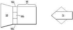
도 2는 본 발명의 실시형태에 의한 탄도성 에어로졸 프린트 헤드 측단면도이다.
도 3은 본 발명의 실시형태에 의한 탄도성 에어로졸 프린트 헤드 평단면도이다.
도 4는 본 발명의 실시형태에 의한 탄도성 에어로졸 프린트 헤드 단면도 (end view)이다.
도 5는 본 발명의 실시형태에 의한 모델화 프린트 헤드에 대한 위치별 유선 속도 등급을 보이는 입자 추적 모델이다.
도 6은 본 발명의 실시형태에 의한 모델화 프린트 헤드에 대한 입자 궤도를 보이는 입자 추적 모델이다.
도 7은 본 분야에서 일반적으로 공지된 프린트 헤드에 대한 위치별 속도 벡터를 보이는 입자 추적 모델이다.
도 8은 본 분야에서 일반적으로 공지된 프린트 헤드에 대한 위치별 입자 궤도를 보이는 입자 추적 모델이다.
도 9는 본 발명의 다른 실시형태에 의한 탄도성 에어로졸 프린트 헤드의 평단면도이다.
도 10은 본 발명의 또 다른 실시형태에 의한 탄도성 에어로졸 프린트 헤드의 평단면도이다.
도 11은 본 발명의 또 다른 실시형태에 의한 모델화 프린트 헤드에 대한 위치별 추진체 속도를 보이는 추적 모델이다.
도 12는 본 발명의 실시형태들에 의한 2종의 상이한 채널 길이에 대한 추진체 압력 대 추진체 속도의 도표이다.
도 13은 본 발명의 또 다른 실시형태에 의한 탄도성 에어로졸 프린트 헤드의 측단면도이다.Like numbers refer to like parts throughout the several views. The figures are shown without considering the scale.
BRIEF DESCRIPTION OF THE DRAWINGS Figure 1 is a sectional side view of a ballistic aerosol printhead of a type generally known in the art.
2 is a cross-sectional view of a ballistic aerosol printhead according to an embodiment of the present invention.
3 is a top cross-sectional view of a ballistic aerosol printhead according to an embodiment of the present invention.
4 is an end view of a ballistic aerosol printhead according to an embodiment of the present invention.
5 is a particle tracking model showing the wire velocity rating for each position of a modeling printhead according to an embodiment of the present invention.
6 is a particle tracking model showing particle trajectories for a modeled printhead according to an embodiment of the present invention.
Figure 7 is a particle tracking model showing positional velocity vectors for print heads generally known in the art.
Figure 8 is a particle tracking model showing particle trajectories by position for a printhead generally known in the art.
9 is a top cross-sectional view of a ballistic aerosol printhead according to another embodiment of the present invention.
10 is a top cross-sectional view of a ballistic aerosol printhead according to another embodiment of the present invention.
FIG. 11 is a tracking model showing the propellant velocity by position for the modeled printhead according to another embodiment of the present invention.
Figure 12 is a plot of propellant pressure versus propellant speed for two different channel lengths in accordance with embodiments of the present invention.
13 is a side cross-sectional view of a ballistic aerosol printhead according to another embodiment of the present invention.
본 발명에 대한 상세를 불필요하게 모호하게 하지 않도록 공지된 출발재료, 가공방법, 부품, 설비 및 기타 공지된 상세 사항들은 단지 요약되거나 생략될 수 있다. 따라서 상세 사항들이 공지된 경우 본원에서 이러한 관련된 상세들이 제안되거나 표기될 수 있다.In order not to unnecessarily obscure the details of the present invention, well-known starting materials, processing methods, parts, equipment, and other known details may be simply summarized or omitted. Thus, if details are known, such related details may be suggested or indicated herein.
본 발명에 의한 프린트 헤드 구조는 탄도성 에어로졸 표지화 시스템의 공기 스트림으로 입자들의 평탄한 (smooth) 분사를 제공한다. 입자 유입구 및 미세채널은 서로 인-라인 정렬되고, 이는 대체로 서로 수직 배향되는 공지된 입자 유입구 및 미세채널의 배열과는 차별된다. 연속 공기 스트림은 입자 유입구 주위로 대칭적인 노즐을 통해 미세채널 내로 집속된다. 이러한 기하 구조에서, 공기는 3차원 (즉 미세채널 어레이 평면 하부 및 상부)으로부터 제공되는 동안 입자 분사는 미세채널과 동일 평면을 이룬다.The printhead structure according to the present invention provides a smooth jet of particles into the air stream of a ballistic aerosol marking system. The particle inlet and the microchannels are in-line aligned with each other, differentiating it from known particle inlet and microchannel arrays that are generally oriented perpendicular to each other. The continuous air stream is directed into a microchannel through a symmetrical nozzle about the particle inlet. In this geometry, the particle jet is coplanar with the microchannels, while the air is provided from three dimensions (i.e., the bottom and top of the microchannel array plane).
전형적인 BAM 프린트 헤드 부시스템 (20)이 도 1에 도시된다. 부시스템 (20)은 몸체 (22)를 포함하고 내부에 라바-타입의 확산관 (24)이 형성된다. 캐리어 예컨대 공기, CO2, 기타 등은 몸체 (22) 제1 근위단 (26)에 주입되어 관 (24) 내에서 추진체 스트림을 형성한다. 또한 몸체 (22)에 다수의 토너 채널들 (28a, b, c, d)이 형성된다. 이들 채널은 물질, 예컨대 유색 토너를 추진체 스트림 내로 전달하도록 구성된다. 채널들 (28a, b, c, d)로부터의 물질 도입이 예를들면, 각각의 정전기 게이트 (30a, b, c, d), 또는 기타 적합한 통로화 메카니즘 (gating mechanism)에 의해 제어될 수 있다. 따라서 위치 (32)에서 관 (24)으로 모험적 공급이 달성된다 (달리, 물질 각각의 채널 (28a, b, c, d)로부터 물질은 위치 (32)로 또한 가압 공급될 수 있다). 물질 및 추진체 스트림이 관 (24)을 통과할 때 압력은 속도로 전환되고, 각각의 채널 (28a, b, c, d)에서 나온 물질들이 혼합되어, 적합한 물질 혼합물은 대략 1 atm의 관 (24)에서, 집속된 고속에어로졸-유사 제트 (34)로서, 일부 실시형태들에서 약343 m/s (초음파) 이상으로 유출된다. 소정의 실시형태들에서, 제트 (34) 중의 입자들은 충돌로 융착 가능한 충분한 운동량으로 가지고 기재 (36)와 충돌한다.A typical BAM print head subsystem 20 is shown in FIG. The sub-system 20 includes a
도 1에서 알 수 있는 바와 같이, 채널들 (28a, b, c, d)의 장축들은 관 (24)의 장축과 거의 수직하게 배치된다. 즉, 제트 (34)로 전달되는 입자 물질들은 전달 방향에 대하여 직각으로 도입된다. 소정 분야들에서는 이러한 배열은 여러 복잡성을 초래한다. 예를들면, 충분한 속도 전개 및 입자 물질 혼합이 가능하도록 관 (24)은 단면 치수 (65 μm x 65 μm)에 비하여 상대적으로 길다 (3000 μm). 그러나, 이는 관 (24) 내에서 에너지의 점성 손실 (및 따라서 비효율성)로 이어진다. 추진체 스트림 흐름 방향에 대하여 채널들 (28a, b, c, d)이 수직 배열로 구성되면, 채널들 (28a, b, c, d) 끝 근처에서 와류가 형성될 수 있다. 이러한 와류는 입자 물질의 정밀한 전달 제어를 방해한다. 또한, 추진체 스트림 흐름 방향에 대하여 수직으로 채널들 (28a, b, c, d)로부터 입자 물질이 도입되면 관 (24) 측벽들과의 입자 충돌로 인하여 제트 초점 이탈이 유발된다.1, the long axes of the
이러한 및 기타 문제점들을 해결하여 시스템 및 방법을 개선하기 위하여, 본 발명은 BAM 시스템 및 방법에서 추진체 스트림으로 물질을 인-라인 도입한다. 추진체 스트림은 입자 유입구에 대하여 하부 및 상부 (또는 측부 또는 상부-하부 및 측부 모두)로부터 대칭적으로 제공되어 미세채널로 제공된다. 유입구 주위로 대칭적 추진체 흐름으로 입자들은 관 측벽들과 충돌하지 않고 추진체 스트림에 매끄럽게 유입된다. 도입 입자들을 포함한 추진체 흐름은 미세채널 내부로 공기 스트림 흐름이 수렴됨으로써 집속된다. 예를들면, 노즐 평면에 대하여 수직한 추가적인 집속화는 미세채널 내부에 라바 노즐들을 이용함으로써 달성된다. 입자들이 주변 유체에 의해 포위되어 강성 장치 측벽들과 직접 충돌하지 않으므로 이러한 구조는 입자들이 장치를 통과하여 이동될 때의 기계적 전단력을 감소시킨다. 이로써 더욱 소형의 강성 출구 오리피스들을 사용하지 않고도 더욱 작은 직경의 제트를 가능하게 하고, 더욱 감소된 전단응력으로 더욱 작은 직경의 제트를 가능하게 한다. 더욱 작은 직경의 제트로 더욱 작은 표적 충돌 영역이 형성되고, 이는 표지화 분야에서 해상도를 개선할 수 있을 뿐 아니라 표적 기재가 생체조직인 경우 약물 전달 분야에서 더욱 통증이 작아지는 이점들을 가진다.In order to solve these and other problems and to improve the system and method, the present invention introduces the material in-line into the propellant stream in the BAM system and method. The propellant stream is provided symmetrically from the bottom and top (or side or top-bottom and sides) relative to the particle inlet to the microchannel. With a symmetrical propellant flow around the inlet, the particles flow smoothly into the propellant stream without colliding with the tube walls. The propellant flow, including the entrained particles, is focused by converging the air stream stream into the microchannel. For example, additional focusing perpendicular to the nozzle plane is achieved by using laser nozzles inside the microchannels. This structure reduces the mechanical shear force when the particles are moved through the device because the particles are not surrounded directly by the surrounding fluids and striking the rigid device sidewalls. This allows smaller diameter jets without the use of smaller rigid exit orifices and allows for smaller diameter jets with a further reduced shear stress. Smaller diameter jets create a smaller target area of impact, which not only improves resolution in the field of labeling, but also has the advantage of being less painful in the field of drug delivery when the target substrate is a biological tissue.
도 2, 3, 및 4는 각각 본 발명의 실시형태에 따른 탄도성 에어로졸 표지화 시스템 (50)의 측면도, 평면도 및 단면도이다. 시스템 (50)은 공급원 구조체 또는 구조체들 (54)과 연통되는 프린트 헤드 몸체 (52)를 포함한다. 설명 목적으로, 몸체 (52) 및 구조체 (54)는 도 2, 3, 및 4에서 상대적으로 동일 척도로 도시된다. 그러나, 많은 실시형태들에서 이들 두 종의 요소들의 척도는 10배수로 차이가 있고, 일부 실시형태들에서100-500 μm 정도인 몸체 (52)는 수 백 mm 이상인 구조체 (54)보다 더욱 작다.Figures 2, 3, and 4 are side, top, and cross-sectional views, respectively, of a ballistic
공급원 구조체 (54)는 가압 추진체 공급원 (56)을 포함하고, 이는 몸체 (52)를 통과하여 유출시키도록 입자들에 대한 캐리어로 작용하는 추진체를 제공한다. 추진체는 압축기, 재충전 또는 비-재충전용 저장소, 물질 상-변화 (예를들면, 고체에서 기체 CO2), 화학 반응 기타 등으로 제공된다. 많은 실시형태들에서, 구조체 (54)에 의해 제공되는 추진체는 기체, 예컨대 CO2, 제습 주변 공기, 및 기타 등일 수 있다. 추진체 제공 관련 추가 상세 사항들은 본원에 참조문헌으로 전체가 통합되는 미국특허 6,511,149에 제공된다. 또한 공급원 구조체 (54)는 저장소 (58)를 포함하고, 여기에는 시스템 (50)에 의해 전달되는 입자들이 담겨있다. 입자들 예시로는, 제한적이지 않지만, 토너, 유기화합물, 금속 및 합금, 의약, 플라스틱, 왁스, 연마제, 단백질, 핵산, 세포 및 기타 등의 미립자, 펠렛, 과립자 기타 등을 포함한다. 저장소 (58)는 적어도 하나의 차원에서 출구 포트 (60)의 원위단으로 경사지거나 집중되도록 구성된다. 또한 저장소 (58)는 추진체 공급원 (56) 내부에서 이에 대하여 추진체가 공급원 (56)을 통과하여 출구 포트 (60)의 상면 및 하면 (및/또는 다른 실시형태들에서 반대 측면들) 위를 지나 출구 포트 (62)로 통과하도록 구성되며, 더욱 하기된다.The
몸체 (52)는 제1 근위단에서 노즐 (64)을 포함한다. 입자 유입 채널 (66)은 노즐 (64) 내부에 배치된다. 입자 유입 채널 (66)은 저장소 (58) 출구 포트 (60)에 대하여 크기 및 위치는 입자들을 수용하도록 구성되는 입구 포트 (68)를 포함한다. 선택적으로, 입자 유입 채널 (66)은 예컨대 전기된 미국특허 6,511,149에 개시되는 하나 이상의 조합된 입자 수송 및 계량 조립체 (μATOM 무버, 70a, 70b)를 더욱 포함한다. 적합하다면, 물질 수송 및 계량은 하나 이상의 다양한 상이한 시스템 및 방법으로 달성될 수 있고, μATOM 무버 (70a, b)는 단지 일 예시일 뿐이다. 입자 유입 채널 (66)은 노즐 (64) 내에 상기 노즐의 적어도 제1 및 제2 반대 면들로부터, 예컨대 상부 및 하부 또는 좌우 측 (또는 모두)으로 실질적으로 균일하게 이격되도록 배치되어, 입자 유입 채널 (66) 및 노즐 (64)의 적어도 두 반대 면들 사이에는 실질적으로 대칭적 제1 및 제2 흐름 영역 (71a, 71b)이 형성된다.The
또한 몸체 (52) 벽 구조체들 (74)에 의해 형성되는 하나 이상의 미세채널 (72)을 포함한다. 미세채널 (72)은 실리콘 또는 유사한 몸체에서 패턴 식각 또는 기타 적합한 방법으로 형성될 수 있다. 예를들면, 미세채널 (72) 어레이는 Si 웨이퍼에 식각되거나, 또는 달리 유리 기재에 적층된 고분자 층들에 식각되어, 몸체 (52) 구조체에 끼워질 수 있다. 벽 구조체들 (74)은 노즐 형상 (76) 및/또는 말단 처리부 (78)가 구비된다 (예컨대 각각 쇄기형, 반원경 또는 유각의 플랫폼 (78a, 78b, 78c) 을 가지는 근위단). 미세채널 (72) (및 벽 구조체들 (74))은 입자 유입 채널 (66)과 집합 영역 (80)에 의해, 예를들면 10-100 μm 이격된다.The
소정의 실시형태들에 의하면, 거대 압력 공급원으로부터 공기를 미세채널로 수렴하기 위하여 사용되는 노즐 구조체는 유리, 플라스틱 (예를들면, 플렉시 글라스), 기타 등을 연마한다. 또한, 소정의 실시형태들에 의하면, 무버 (70a, b)를 미세채널 (72)과 정렬시키기 위하여, μAtom 무버 및 미세채널을 가지는 칩들에서 활주될 수 있는 정렬 홈들 (미도시)이 있는 측벽들이 이용될 수 있다.According to certain embodiments, the nozzle structure used to converge air from the giant pressure source into the microchannel polish glass, plastic (e.g., plexiglass), etc. In addition, according to certain embodiments, side walls with alignment grooves (not shown) that can be slid in microchannel and microchanneled chips to align the
작동에 있어서, 예컨대 중력, 정- 또는 부-압력, 정전기, 기타 등에 의해 입자들이 저장소 (58)로부터 입자 유입 채널 (66)로 공급된다. 추진체는 입자 유입 채널 (66) 상부 및 하부 (및/또는 양측)에서 가압 추진체 공급원 (56)에 의해 공급된다. 추진체는 노즐 (64)에 의해 입자 유입 채널 (66)과 대칭적으로 정렬되는 미세채널 (72)로 집속된다. μATOM 무버 (70a, b)는 출구 포트 (82)에서 추진체 스트림으로 들어가는 제어된 입자 양을 계량한다. 출구 포트 (82)를 지나는 추진체 흐름과 함께 입자들을 계량하여 입자들을 미세채널 (72)를 통과시킨다. 추진체 및 입자들 속도는 미세채널 (72)의 노즐 외형에 의해 증가되어 고속의 집속 입자 스트림은 예를들면, 기재 (84)을 지향하여 채널들에서 유출된다.In operation, particles are supplied from the
상기 기하 구조에 의한 프린트 헤드를 모델화하고 모델화 장치의 다양한 측면들을 검사하여 도 5 및 6에 도시하였다. 모델의 입구 압력은 저장소 입구에서 1.25 atm이고 미세채널 입구에서1.3 atm이었다. 도 5는 위치별 유선 속도 등급을 보이는 입자 추적 모델이고, 입자는 도면 좌측에서 우측으로 흐른다. 도시된 바와 같이, 추진체가 입자 공급원의 상부 및 하부 (또는 각각의 측면 또는 모두)에 대칭적으로 제공되는 상기 프린트 헤드 기하 구조로 인하여 공기 유선은 입자 유입 채널 주위 및 미세채널 내부로 로 평탄하게 수렴된다. 도 6은 입자 궤도를 보이는 입자 추적 모델이고, 역시 입자는 도면에서 좌측에서 우측으로 흐른다. 개시된 프린트 헤드 기하 구조는 주입된 입자들에 대하여 “평탄” 궤도를 제공한다는 것을 알 수 있다.The geometry of the print head is modeled and various aspects of the modeling device are examined and shown in FIGS. 5 and 6. FIG. The inlet pressure of the model was 1.25 atm at the reservoir inlet and 1.3 atm at the microchannel inlet. FIG. 5 is a particle tracking model showing wire velocity grades according to positions, and the particles flow from the left side to the right side of the drawing. As shown, due to the printhead geometry, in which the propellant is symmetrically provided to the top and bottom (or each side or both) of the particle source, the air stream is flattened to converge around the particle inlet channels and into the microchannels do. Fig. 6 is a particle tracking model showing particle trajectories, and the particles also flow from left to right in the drawing. It can be seen that the disclosed printhead geometry provides a " flat " trajectory for the implanted particles.
도 5 및 6에 도시된 상태는 입자 입구가 미세채널에 수직하게 배열되는 공지 구조들과는 차별된다. 이들 공지 구조에서는, 각각 위치별 속도 등급 및 입자 궤도를 보이는 선택된 공지 프린트 헤드 기하 구조의 입자 추적 모델이고 입자들은 우측에서 좌측으로 흐르는 도 7 및 8에 도시된 바와 같이 와류가 토너 입구 내부에 형성되어 입자들은 공기 주요 스트림에 유입될 때 벽들과 다중 충돌한다. (도 7 및 8에 적용된 프린트 헤드 모델은 길이 4mm 및 폭 84 μm의 채널을 포함하고, 라바 노즐은 750 μm 높이의 토너 입구 우측 단에 있다. 공기 압력은 6 atm으로 설정되었다. 토너 입구 압력은 1 atm 이었다) 도 7 및 8은 선행 BAM 프린트 헤드 구조의 비효율성을 보이고, 소정의 분야에서 본 구조에 의해 제공되는 이점들을 강조하는 것이다.The states shown in Figures 5 and 6 are different from known structures in which the particle entrance is arranged perpendicular to the microchannel. In these known structures, a particle tracking model of a selected known printhead geometry showing the velocity grade and particle trajectory for each position, respectively, and particles are formed inside the toner inlet as shown in Figs. 7 and 8 flowing from right to left The particles multiply with the walls when entering the air main stream. (The printhead model applied in Figures 7 and 8 includes channels of length 4 mm and width 84 [mu] m, and the laba nozzle is at the right end of the toner inlet at a height of 750 [mu] m .. The air pressure was set at 6 atm. 1 < / RTI > atm. Figures 7 and 8 illustrate the inefficiency of the preceding BAM printhead structure and highlight the benefits provided by the present architecture in some fields.
도 2를 다시 참조하면, 공기를 미세채널 (72)로 수렴하는 노즐 (64) 각도 ф로 유입 채널 (66) 내부에 필요한 압력을 제어하여 입구 내부로의 공기 흐름을 방지한다. ф가 작아질수록, 입자 유입 출구 주위에서 공기 속도 v는 커진다. 총 압력은 일정하므로, 역 흐름 방지를 위하여 입구 내부에서 균형을 이루어야 하는 유입구 출구에서의 정압은 베르누이 법칙에 따라 감소된다:Referring again to FIG. 2, the required pressure inside the

입자들은 미세채널 (72) 앞에서 공기 스트림으로 도입된다. 따라서 수렴된 공기 유선으로 인하여 입자들은 노즐 평면에서 미세채널 (72) 내부로 집속된다 (도 6). 이로써 적합한 미세채널 길이를 선택함으로써 출력 스폿 (예를들면, 픽셀) 크기는 극대화된다.The particles are introduced into the air stream in front of the
평탄 입자 궤도는 입자 유입 채널 (66)로부터 미세채널 (72)로의 느리지만 연속된 추진체 스트림에 의해 획득된다. 도 9에 도시된 하나의 실시형태에 따르면, 하전 입자들 단속은 출구 포트 (82)에서 ON 및 OFF 상태를, 예컨대 제어기 (92)에 의해 전환시키는 게이트 전극 (90)을 통해 달성될 수 있다. 게이트 전압은 유입 채널 (66)로부터 미세채널 (72)로의, 예컨대 입자 유입 채널 내부 정압으로부터 계산되거나 또는 적합한 센서(들) (94)로 측정될 수 있는 추진체 유속 함수로써 제어될 수 있다.A flat particle trajectory is obtained by a slow but continuous propellant stream from the
도 10에 도시된 대안적 실시형태에서, 개별 μAtom 트랙들에 의해 개별 미세채널로의 입자 공급을 제어하는 대신, 단일한 프린트 헤드-폭의 μAtom 무버 (96)가 연속적으로 입자들을 미세채널로 수송하고, (출구 포트 (82)와 떨어져 있는) 개별 전극 (98a, 98b, 98c) 기타 등이 이러한 μAtom 무버로의 입자들 통로를 제어한다. 그러나, 수송 부시스템은 모든 실시형태들에 대하여 필수적인 것은 아니라는 것을 이해하여야 한다. 예를들면, 약물 전달 실시형태들에서, 주입은 저장소 내에 담겨 있는 전달 약물의 설정 부피에 의해 제어될 수 있다 (예를들면, 주입되면 저장소 총 내용물은 소모된다). 약물 입자 전달의 경우, 예를들면 유동층 혼합기 또는 기타 공지 기구에 의해. "연무"가 형성된다.In the alternative embodiment shown in Fig. 10, instead of controlling particle feed to individual microchannels by separate μAtom tracks, a single printhead-
본원에 개시된 프린트 헤드 기하 구조에 의해 제공되는 여러 이점들 중에서 현존 구조에서보다 더 짧은 미세채널을 이용하는 것이다. 본 발명에 의하면, 미세채널은 추진체 제트를 기재에 최종적으로 집속하기 위하여 (구성에 따라) 주로 또는 절대적으로 필요하다. 추진체 공급의 다른 모든 부분들은 거대 (> 1mm) 치수를 유지한다. 미세채널 내부에서 점성 손실이 감소하면 도 11 (추진체 흐름 속도 벡터, 도면에서 좌측에서 우측으로 흐름) 및 도 12 (채널 길이 함수로서 추진체/입자 출구 속도)에 나타낸 바와 같이 더 낮은 입구 압력으로 추진체를 높은 (예를들면, 초음파) 속도로 가속시킬 수 있다.Among the various advantages provided by the printhead geometry disclosed herein is the use of shorter microchannels than in existing structures. According to the present invention, the microchannels are primarily or absolutely necessary (depending on the configuration) to ultimately focus the propellant jet onto the substrate. All other parts of the propellant supply maintain a large (> 1 mm) dimension. As the viscous losses inside the microchannels decrease, the propellant is drawn to the lower inlet pressure as shown in Figure 11 (propellant flow velocity vector, left to right in the figure) and Figure 12 (propellant / particle exit velocity as a function of channel length) And can be accelerated at high (e.g., ultrasonic) speeds.
도 13에 도시된 대안적 프린트 헤드 구조에 의하면, 미세채널들이 제공되지 않는다. 노즐 (64)은 추진체가 직접 마이크로 슬릿 (100)을 통과하도록 집속시킨다. 소정의 실시형태들에서, 미세채널 실시형태들과 비교하여 마이크로 슬릿 (100) 길이가 증가될 필요가 있다. 이러한 길이는 수 cm 또는 그 이상의 정도이다. 이러한 실시형태들에서 마이크로 슬릿에서는 또한 난류가 감소될 수 있다.According to the alternative printhead structure shown in Fig. 13, no microchannels are provided. The
상기된 바와 같이, 하전 입자들은 개별 mAtom 무버 (70a, 70b) 및 기타 등에 의해 개별 미세채널로 제공된다. 즉, 하나 이상의 μAtom 무버는 유입 채널 (66) 내부에 배치될 수 있다. 소정의 실시형태들에서, 각각의 μAtom 무버는 도 3에 도시된 예컨대 특유한 입자 저장소 (58a-70a 및 58b-70b)와 연통된다. μAtom 무버 (70a, 70b)는 (거대) 유동층 상으로부터 입자들을 공급하는 거대 Atom 무버 (미도시)와 연결될 수 있다. 일반적으로, 프린트 헤드 해상도는 적용되는 μAtom 무버, 게이트 전극, 및 미세채널의 밀도로 결정된다. 일 실시예에서, 미세채널 및 μAtom 무버는 인쇄 해상도를 300 dpi까지 제공하지만, 기타 인쇄 해상도 역시 본 발명에 의해 고려된다.As noted above, the charged particles are provided as discrete microchannels by
본원에 개시되는 구조체 제1 부분이 제2 부분 "위" 또는 "상부"에 있다고 언급될 때, 이는 제2 부분 위에 바로, 또는 제1 및 제2 부분들 사이에 있는 개재 구조체 또는 구조체들 위에 있을 수 있다. 또한, 제1 부분이 제2 부분 "위" 또는 "상부"에 있다고 언급될 때, 제1 부분은 제2 부분 전체를 커버하거나 또는 단지 제2 부분 일부를 덮을 수 있다.When the first portion of the structure disclosed herein is referred to as being on the second portion "above" or "upper ", it may be directly above the second portion, or on the intervening structure or structures between the first and second portions . Further, when the first portion is referred to as being in the second portion "above" or "upper ", the first portion may cover the entire second portion or may cover only a portion of the second portion.
현대 미세기계 장치에 대한 물리학 및 이의 제조 방법은 절대적이지 않고, 오히려 원하는 장치 및/또는 결과를 얻기 위한 통계적 역량이다. 공정 재현성, 제조 설비 청결도, 출발 및 가공 재료의 순도 및 기타 등에 대하여 극도로 주의를 기울려도, 편차 및 불완전성이 존재한다. 따라서, 본 발명의 설명 또는 청구범위에 대한 어떠한 제한도 절대적인 것으로 읽혀서는 아니된다. 청구범위에 대한 한정은 이러한 한정을 포함하여 본 발명의 경계를 한정하기 위한 의도이다. 이를 더욱 강조하기 위하여, “실질적으로”라는 용어가 청구범위 제한 (편차 및 불완전성에 대한 고려는 이러한 용어로 사용되는 이들 제한으로 국한되지는 않지만) 및/또는 설명과 관련하여 자주 사용된다. 본 발명 자체에 대한 제한을 정밀하게 규정하는 것이 난해하므로, 이러한 용어는 "상당한 정도로”, “거의 구현될 수 있는”, “기술적 한계 내에서”, 및 기타 등으로 해석되어야 한다.The physics of modern micromechanical devices and their manufacturing methods are not absolute, but rather are a statistical capability to obtain desired devices and / or results. Excessive attention is paid to process reproducibility, cleanliness of the manufacturing facility, purity of the starting and processing materials, and the like, but deviations and imperfections exist. Accordingly, no limitations on the description or the claims of the invention shall be read as absolute. The scope of the claims is intended to limit the scope of the invention, including these limitations. To further emphasize this, the term " substantially " is often used in relation to claim limitations (although deviations and incompleteness considerations are not limited to these limitations used in these terms) and / or descriptions. As it is difficult to precisely define the limitations of the present invention itself, such terms should be interpreted as being "substantially", "substantially implementable", "within technical limits", and the like.
상기 설명에서 실시예들 및 변형들이 제시되지만, 다수의 변형이 존재할 수 있고 이들 실시예들은 단지 대표적인 것이고 본 발명의 범위, 적용 가능성 또는 구성을 어떠한 방식으로도 제한하는 것은 아니라는 것을 이해하여야 한다. 상기 및 기타 다양한 특징부 및 기능, 또는 이들의 대안은 바람직하게는 많은 다른 상이한 시스템 또는 응용 분야들로 조합된다. 다양한 현재 예측 불가하거나 예상되지 않은 대안들, 변형, 변경, 또는 이들에 대한 개선들은 당업자에 의해 이루어질 수 있을 것이고, 이는 이하 청구범위에 포괄되는 것이다.Although the embodiments and variations are presented in the foregoing description, it should be understood that there may be many variations and these embodiments are merely representative and are not intended to limit the scope, applicability or configuration of the invention in any way. These and various other features and functions, or alternatives thereof, are preferably combined into many other different systems or applications. Various presently unpredictable or unexpected alternatives, modifications, alterations, or improvements thereto may be made by those skilled in the art, which is encompassed by the following claims.
따라서, 상기 설명은 당업자에게 본 발명의 구현에 대한 용이한 안내를 제공하는 것이고 상기 실시예들에 대한 다양한 기능상 및 구성상의 변경은 청구범위에 의해 정의되는 사상 및 범위로부터 일탈됨이 없이 가능한 것이다.Accordingly, the above description provides one skilled in the art with an easy-to-understand guide to the implementation of the present invention, and various functional and structural changes to the embodiments are possible without departing from the spirit and scope defined by the claims.
Claims (7)
Translated fromKorean노즐 및 미세채널 영역이 내부에 형성되는 물질 토출기 몸체;
상기 미세채널 영역 내부에 배치되고, 노즐 외형을 형성하는 벽 구조체들을 포함하는 미세채널;
상기 노즐 내부에 배치되고 상기 노즐의 적어도 제1 및 제2 반대 면들로부터 실질적으로 균등하게 이격되며, 이로써 상기 입자 유입 채널 및 상기 노즐의 상기 적어도 2 반대 면들 사이에 실질적으로 대칭적 제1 및 제2 흐름 영역이 형성되는 입자 유입 채널;
상기 입자 유입 채널 내부에 배치되는 적어도 하나의 정전기 입자 수송 부시스템;
입자 물질을 전달하기 위한 상기 입자 유입 채널과 연통적으로 연결되는 입자 저장소;
상기 노즐과 연통적으로 연결되는 추진체 공급원으로 구성되고;
상기 입자 유입 채널은, 상기 추진체 공급원에 대하여 및 상기 노즐 내부에서, 상기 추진체 공급원에 의하여 제공되는 추진체가 상기 제1 및 제2 흐름 영역 내부의 상기 입자 유입 채널을 지나 실질적으로 균일하게 흐르도록 배치되고;
이에 따라 입자 물질은 상기 입자 저장소에서 상기 입자 유입 채널로 제공되며, 상기 입자 물질은 상기 정전기 입자 수송 부시스템에 의해 계량되고 상기 정전기 입자 수송 부시스템으로부터 상기 제1 및 제2 흐름 영역 내부의 상기 입자 유입 채널을 지나 실질적으로 균일하게 흐르는 추진체에 의해 수송되고, 상기 추진체에 의해 상기 미세채널 영역을 지나 상기 기재를 향하여 상기 물질 토출기 몸체로부터 배출되는, 입자 물질을 기재에 선택적으로 적층하는 장치.An apparatus for selectively depositing particulate material on a substrate, comprising:
A material discharge body having a nozzle and a fine channel region formed therein;
A microchannel disposed within the microchannel region and including wall structures forming a nozzle contour;
Wherein the nozzle is disposed within the nozzle and is substantially evenly spaced from at least the first and second opposing surfaces of the nozzle such that there is substantially symmetrical first and second A particle inlet channel in which a flow region is formed;
At least one electrostatic particle transport subsystem disposed within the particle inlet channel;
A particle reservoir communicatively coupled to the particle inlet channel for delivering particulate material;
A propellant source communicatively connected to the nozzle;
The particle inlet channel is disposed such that the propellant provided by the propellant source flows substantially uniformly through the particle inlet channel within the first and second flow regions with respect to the propellant source and within the nozzle ;
Whereby particulate matter is provided to the particle entry channel in the particle reservoir and wherein the particulate matter is metered by the electrostatic particle transport subsystem system and the particles in the first and second flow regions from the electrostatic particle transport subsystem, Wherein the material is transported by a propellant that flows substantially uniformly through the inlet channel and is discharged from the material discharge body toward the substrate via the microchannel region by the propellant.
Applications Claiming Priority (2)
| Application Number | Priority Date | Filing Date | Title |
|---|---|---|---|
| US14/099,873US10933636B2 (en) | 2013-12-06 | 2013-12-06 | Print head design for ballistic aerosol marking with smooth particulate injection from an array of inlets into a matching array of microchannels |
| US14/099,873 | 2013-12-06 |
Publications (2)
| Publication Number | Publication Date |
|---|---|
| KR20150066445Atrue KR20150066445A (en) | 2015-06-16 |
| KR102534891B1 KR102534891B1 (en) | 2023-05-23 |
Family
ID=52023172
Family Applications (1)
| Application Number | Title | Priority Date | Filing Date |
|---|---|---|---|
| KR1020140164347AActiveKR102534891B1 (en) | 2013-12-06 | 2014-11-24 | Print head design for ballistic aerosol marking with smooth particulate injection from an array of inlets into a matching array of microchannels |
Country Status (4)
| Country | Link |
|---|---|
| US (2) | US10933636B2 (en) |
| EP (1) | EP2881259B1 (en) |
| JP (1) | JP6560858B2 (en) |
| KR (1) | KR102534891B1 (en) |
Families Citing this family (5)
| Publication number | Priority date | Publication date | Assignee | Title |
|---|---|---|---|---|
| CN106513193B (en)* | 2015-09-06 | 2019-03-22 | 东莞市瑞迪三维电子科技有限公司 | Electrostatic 3D printer and printing method thereof |
| US9993839B2 (en)* | 2016-01-18 | 2018-06-12 | Palo Alto Research Center Incorporated | System and method for coating a substrate |
| CN110028985B (en)* | 2019-04-26 | 2022-06-10 | 河南百优福生物能源有限公司 | Method for preparing high-quality fuel oil and/or chemical raw materials from biomass pyrolysis liquid |
| KR102849976B1 (en) | 2019-07-11 | 2025-08-28 | 더 리젠츠 오브 더 유니버시티 오브 미시건 | Aerosol printing of special fluids |
| CN119300969A (en) | 2022-04-13 | 2025-01-10 | 阿普雷奇亚制药有限责任公司 | Systems and methods for additive manufacturing using an omnidirectional magnetic motion device |
Citations (3)
| Publication number | Priority date | Publication date | Assignee | Title |
|---|---|---|---|---|
| US4822267A (en)* | 1985-09-24 | 1989-04-18 | Alfred Walz | Apparatus for producing superfine powder in spherical form |
| US6416158B1 (en)* | 1998-09-30 | 2002-07-09 | Xerox Corporation | Ballistic aerosol marking apparatus with stacked electrode structure |
| WO2003091460A1 (en)* | 2002-04-24 | 2003-11-06 | The Boc Group Plc | Lance for injecting particulate material into liquid metal |
Family Cites Families (16)
| Publication number | Priority date | Publication date | Assignee | Title |
|---|---|---|---|---|
| US6116718A (en) | 1998-09-30 | 2000-09-12 | Xerox Corporation | Print head for use in a ballistic aerosol marking apparatus |
| US6328409B1 (en) | 1998-09-30 | 2001-12-11 | Xerox Corporation | Ballistic aerosol making apparatus for marking with a liquid material |
| KR100839002B1 (en)* | 1998-09-30 | 2008-06-18 | 제록스 코포레이션 | Spray device for particulate marking material, deposition apparatus and deposition method for particulate marking material, substrate marking method and cartridge |
| US6511850B1 (en)* | 1999-07-13 | 2003-01-28 | The Texas A&M University System | Pneumatic nebulizing interface to convert an analyte-containing fluid stream into an aerosol, method for using same and instruments including same |
| WO2001015800A1 (en)* | 1999-08-27 | 2001-03-08 | Picogram, Inc. | Method and device for performing operations at charged microlocations |
| US6293659B1 (en) | 1999-09-30 | 2001-09-25 | Xerox Corporation | Particulate source, circulation, and valving system for ballistic aerosol marking |
| US6328436B1 (en) | 1999-09-30 | 2001-12-11 | Xerox Corporation | Electro-static particulate source, circulation, and valving system for ballistic aerosol marking |
| US6521297B2 (en)* | 2000-06-01 | 2003-02-18 | Xerox Corporation | Marking material and ballistic aerosol marking process for the use thereof |
| GB0226160D0 (en)* | 2002-11-08 | 2002-12-18 | Diagnoswiss Sa | Apparatus for dispensing a sample in electrospray mass spectrometers |
| US8020975B2 (en) | 2004-12-03 | 2011-09-20 | Xerox Corporation | Continuous particle transport and reservoir system |
| US7938341B2 (en) | 2004-12-13 | 2011-05-10 | Optomec Design Company | Miniature aerosol jet and aerosol jet array |
| KR100794657B1 (en)* | 2006-06-28 | 2008-01-14 | 삼성전자주식회사 | Method of forming barrier metal film in semiconductor device |
| DK2069673T3 (en)* | 2006-08-12 | 2013-11-04 | Pelt Colleen K Van | NANOLITE FLOWRATE SEPARATION AND ELECTROSPRAY DEVICE WITH PLUG AND PLAY PRESSURE CONNECTIONS AND MULTIPLE SENSOR DIAGNOSIS MONITORING SYSTEM |
| TWI482662B (en)* | 2007-08-30 | 2015-05-01 | Optomec Inc | Mechanically integrated and tightly coupled print heads and spray sources |
| US8388569B2 (en)* | 2011-04-19 | 2013-03-05 | Xerox Corporation | Delivery devices and methods with collimated gas stream and particle source |
| JP2015511270A (en)* | 2012-01-27 | 2015-04-16 | エヌディーエスユー リサーチ ファウンデーション | Microcold spray direct writing system and method for printed microelectronics |
- 2013
- 2013-12-06USUS14/099,873patent/US10933636B2/enactiveActive
- 2014
- 2014-11-24EPEP14194541.0Apatent/EP2881259B1/enactiveActive
- 2014-11-24KRKR1020140164347Apatent/KR102534891B1/enactiveActive
- 2014-11-26JPJP2014238959Apatent/JP6560858B2/enactiveActive
- 2021
- 2021-03-01USUS17/188,603patent/US20210178758A1/ennot_activeAbandoned
Patent Citations (3)
| Publication number | Priority date | Publication date | Assignee | Title |
|---|---|---|---|---|
| US4822267A (en)* | 1985-09-24 | 1989-04-18 | Alfred Walz | Apparatus for producing superfine powder in spherical form |
| US6416158B1 (en)* | 1998-09-30 | 2002-07-09 | Xerox Corporation | Ballistic aerosol marking apparatus with stacked electrode structure |
| WO2003091460A1 (en)* | 2002-04-24 | 2003-11-06 | The Boc Group Plc | Lance for injecting particulate material into liquid metal |
Also Published As
| Publication number | Publication date |
|---|---|
| EP2881259A1 (en) | 2015-06-10 |
| EP2881259B1 (en) | 2017-06-07 |
| US20150158295A1 (en) | 2015-06-11 |
| US20210178758A1 (en) | 2021-06-17 |
| JP2015112600A (en) | 2015-06-22 |
| JP6560858B2 (en) | 2019-08-14 |
| US10933636B2 (en) | 2021-03-02 |
| KR102534891B1 (en) | 2023-05-23 |
Similar Documents
| Publication | Publication Date | Title |
|---|---|---|
| US20210178758A1 (en) | Print Head Design for Ballistic Aerosol Marking with Smooth Particulate Injection from an Array of Inlets into a Matching Array of Microchannels | |
| AU745870B2 (en) | Stabilized capillary microjet and devices and methods for producing same | |
| US6405936B1 (en) | Stabilized capillary microjet and devices and methods for producing same | |
| KR102100083B1 (en) | Device and method for administering particles, aligned with the use of an acoustic field, in free-falling drops | |
| US9470617B2 (en) | Flow cytometry apparatus | |
| EP2144759B1 (en) | Printer deflector mechanism including liquid flow | |
| US20180015730A1 (en) | Apparatuses and Methods for Stable Aerosol-Based Printing Using an Internal Pneumatic Shutter | |
| CN101098734A (en) | Micro aerosol nozzle and aerosol nozzle array | |
| JPS604786B2 (en) | ink mist printing device | |
| JP2018110266A (en) | Material deposition system and method for depositing material on substrate | |
| CN100339219C (en) | liquid jet head | |
| US20160243827A1 (en) | Controlling air and liquid flows in a two-dimensional printhead array | |
| JP2023015082A (en) | Droplet dispensing system | |
| CN109203451B (en) | Novel biological printing method based on air flow transmission | |
| CN110553951B (en) | Particle impact and observation device and method | |
| EP3448684B1 (en) | Industrial printhead | |
| Li et al. | Asymmetric micro-ratchets regulated drop dispensing on bamboo mimetic surface | |
| Kim et al. | Control of charged droplets using electrohydrodynamic repulsion for circular droplet patterning | |
| CN219789662U (en) | Jet printing equipment | |
| CN109772485A (en) | Detection system based on micro-droplets | |
| US11547993B2 (en) | Droplet ejectors with target media | |
| US20090027457A1 (en) | Fluid ejection device | |
| Panchawagh et al. | Silicon micromachined continuous inkjet (CIJ) printhead with integral deflection and guttering | |
| Tseng | 10 Microdroplet Generators | |
| Völkel et al. | Ballistic aerosol marking |
Legal Events
| Date | Code | Title | Description |
|---|---|---|---|
| PA0109 | Patent application | Patent event code:PA01091R01D Comment text:Patent Application Patent event date:20141124 | |
| PG1501 | Laying open of application | ||
| A201 | Request for examination | ||
| PA0201 | Request for examination | Patent event code:PA02012R01D Patent event date:20191120 Comment text:Request for Examination of Application Patent event code:PA02011R01I Patent event date:20141124 Comment text:Patent Application | |
| A201 | Request for examination | ||
| E902 | Notification of reason for refusal | ||
| PE0902 | Notice of grounds for rejection | Comment text:Notification of reason for refusal Patent event date:20210226 Patent event code:PE09021S01D Comment text:Patent Application Patent event date:20141124 Patent event code:PA02011R01I | |
| AMND | Amendment | ||
| E601 | Decision to refuse application | ||
| PE0601 | Decision on rejection of patent | Patent event date:20210826 Comment text:Decision to Refuse Application Patent event code:PE06012S01D Patent event date:20210226 Comment text:Notification of reason for refusal Patent event code:PE06011S01I | |
| X091 | Application refused [patent] | ||
| AMND | Amendment | ||
| PX0901 | Re-examination | Patent event code:PX09011S01I Patent event date:20210826 Comment text:Decision to Refuse Application Patent event code:PX09012R01I Patent event date:20210420 Comment text:Amendment to Specification, etc. | |
| PX0601 | Decision of rejection after re-examination | Comment text:Decision to Refuse Application Patent event code:PX06014S01D Patent event date:20211028 Comment text:Amendment to Specification, etc. Patent event code:PX06012R01I Patent event date:20210927 Comment text:Decision to Refuse Application Patent event code:PX06011S01I Patent event date:20210826 Comment text:Amendment to Specification, etc. Patent event code:PX06012R01I Patent event date:20210420 Comment text:Notification of reason for refusal Patent event code:PX06013S01I Patent event date:20210226 | |
| X601 | Decision of rejection after re-examination | ||
| J201 | Request for trial against refusal decision | ||
| PJ0201 | Trial against decision of rejection | Patent event date:20211129 Comment text:Request for Trial against Decision on Refusal Patent event code:PJ02012R01D Patent event date:20211028 Comment text:Decision to Refuse Application Patent event code:PJ02011S01I Patent event date:20210826 Comment text:Decision to Refuse Application Patent event code:PJ02011S01I Appeal kind category:Appeal against decision to decline refusal Appeal identifier:2021101003060 Request date:20211129 | |
| J301 | Trial decision | Free format text:TRIAL NUMBER: 2021101003060; TRIAL DECISION FOR APPEAL AGAINST DECISION TO DECLINE REFUSAL REQUESTED 20211129 Effective date:20220930 | |
| PJ1301 | Trial decision | Patent event code:PJ13011S01D Patent event date:20220930 Comment text:Trial Decision on Objection to Decision on Refusal Appeal kind category:Appeal against decision to decline refusal Request date:20211129 Decision date:20220930 Appeal identifier:2021101003060 | |
| PS0901 | Examination by remand of revocation | ||
| E902 | Notification of reason for refusal | ||
| PE0902 | Notice of grounds for rejection | Comment text:Notification of reason for refusal Patent event date:20221031 Patent event code:PE09021S01D | |
| GRNO | Decision to grant (after opposition) | ||
| PS0701 | Decision of registration after remand of revocation | Patent event date:20230216 Patent event code:PS07012S01D Comment text:Decision to Grant Registration Patent event date:20220930 Patent event code:PS07011S01I Comment text:Notice of Trial Decision (Remand of Revocation) | |
| GRNT | Written decision to grant | ||
| PR0701 | Registration of establishment | Comment text:Registration of Establishment Patent event date:20230517 Patent event code:PR07011E01D | |
| PR1002 | Payment of registration fee | Payment date:20230518 End annual number:3 Start annual number:1 | |
| PG1601 | Publication of registration |