KR20150065231A - Data transmission method and data reception method, terminal and base station - Google Patents
Data transmission method and data reception method, terminal and base stationDownload PDFInfo
- Publication number
- KR20150065231A KR20150065231AKR1020130150218AKR20130150218AKR20150065231AKR 20150065231 AKR20150065231 AKR 20150065231AKR 1020130150218 AKR1020130150218 AKR 1020130150218AKR 20130150218 AKR20130150218 AKR 20130150218AKR 20150065231 AKR20150065231 AKR 20150065231A
- Authority
- KR
- South Korea
- Prior art keywords
- mcs
- mcs table
- qam
- terminal
- information
- Prior art date
- Legal status (The legal status is an assumption and is not a legal conclusion. Google has not performed a legal analysis and makes no representation as to the accuracy of the status listed.)
- Withdrawn
Links
Images


Classifications
- H—ELECTRICITY
- H04—ELECTRIC COMMUNICATION TECHNIQUE
- H04L—TRANSMISSION OF DIGITAL INFORMATION, e.g. TELEGRAPHIC COMMUNICATION
- H04L1/00—Arrangements for detecting or preventing errors in the information received
- H04L1/0001—Systems modifying transmission characteristics according to link quality, e.g. power backoff
- H04L1/0002—Systems modifying transmission characteristics according to link quality, e.g. power backoff by adapting the transmission rate
- H04L1/0003—Systems modifying transmission characteristics according to link quality, e.g. power backoff by adapting the transmission rate by switching between different modulation schemes
- H—ELECTRICITY
- H04—ELECTRIC COMMUNICATION TECHNIQUE
- H04B—TRANSMISSION
- H04B7/00—Radio transmission systems, i.e. using radiation field
- H04B7/02—Diversity systems; Multi-antenna system, i.e. transmission or reception using multiple antennas
- H04B7/04—Diversity systems; Multi-antenna system, i.e. transmission or reception using multiple antennas using two or more spaced independent antennas
- H04B7/06—Diversity systems; Multi-antenna system, i.e. transmission or reception using multiple antennas using two or more spaced independent antennas at the transmitting station
- H04B7/0613—Diversity systems; Multi-antenna system, i.e. transmission or reception using multiple antennas using two or more spaced independent antennas at the transmitting station using simultaneous transmission
- H04B7/0615—Diversity systems; Multi-antenna system, i.e. transmission or reception using multiple antennas using two or more spaced independent antennas at the transmitting station using simultaneous transmission of weighted versions of same signal
- H04B7/0619—Diversity systems; Multi-antenna system, i.e. transmission or reception using multiple antennas using two or more spaced independent antennas at the transmitting station using simultaneous transmission of weighted versions of same signal using feedback from receiving side
- H04B7/0621—Feedback content
- H04B7/0632—Channel quality parameters, e.g. channel quality indicator [CQI]
- H—ELECTRICITY
- H04—ELECTRIC COMMUNICATION TECHNIQUE
- H04L—TRANSMISSION OF DIGITAL INFORMATION, e.g. TELEGRAPHIC COMMUNICATION
- H04L1/00—Arrangements for detecting or preventing errors in the information received
- H04L1/0001—Systems modifying transmission characteristics according to link quality, e.g. power backoff
- H04L1/0023—Systems modifying transmission characteristics according to link quality, e.g. power backoff characterised by the signalling
- H04L1/0026—Transmission of channel quality indication
- H—ELECTRICITY
- H04—ELECTRIC COMMUNICATION TECHNIQUE
- H04L—TRANSMISSION OF DIGITAL INFORMATION, e.g. TELEGRAPHIC COMMUNICATION
- H04L27/00—Modulated-carrier systems
- H04L27/32—Carrier systems characterised by combinations of two or more of the types covered by groups H04L27/02, H04L27/10, H04L27/18 or H04L27/26
- H04L27/34—Amplitude- and phase-modulated carrier systems, e.g. quadrature-amplitude modulated carrier systems
- H—ELECTRICITY
- H04—ELECTRIC COMMUNICATION TECHNIQUE
- H04L—TRANSMISSION OF DIGITAL INFORMATION, e.g. TELEGRAPHIC COMMUNICATION
- H04L5/00—Arrangements affording multiple use of the transmission path
- H04L5/003—Arrangements for allocating sub-channels of the transmission path
- H04L5/0048—Allocation of pilot signals, i.e. of signals known to the receiver
Landscapes
- Engineering & Computer Science (AREA)
- Signal Processing (AREA)
- Computer Networks & Wireless Communication (AREA)
- Quality & Reliability (AREA)
- Mobile Radio Communication Systems (AREA)
Abstract
Translated fromKoreanDescription
Translated fromKorean본 발명에서는 복수개의 기지국들이 존재하는 셀룰러(cellular) 이동 통신 시스템에서 기지국과 단말 간 정보 교환 방법 및 장치에 관한 것으로, 특히 여러 기지국들이 협력하여 단말의 하향링크 전송을 지원하는 협력 시스템(Cooperative multi-point : CoMP)에서 MCS 테이블 및 CQI 테이블 정보를 효율적으로 교환하는 방법 및 장치에 관한 것이다.The present invention relates to a method and an apparatus for exchanging information between a base station and a mobile station in a cellular mobile communication system in which a plurality of base stations exist. In particular, a cooperative multi- point: CoMP) to efficiently exchange MCS table and CQI table information.
이동통신 시스템은 초기의 음성 위주의 서비스를 제공하던 것에서 벗어나 데이터 서비스 및 멀티미디어 서비스 제공을 위해 고속, 고품질의 무선 패킷 데이터 통신 시스템으로 발전하고 있다. 최근 3GPP의 HSDPA(High Speed Downlink Packet Access), HSUPA(High Speed Uplink Packet Access), LTE (Long Term Evolution), LTE-A (Long Term Evolution Advanced), 3GPP2의 HRPD(High Rate Packet Data), 그리고 IEEE의 802.16 등 다양한 이동 통신 표준이 고속, 고품질의 무선 패킷 데이터 전송 서비스를 지원하기 위해 개발되었다. 특히 LTE 시스템은 고속 무선 패킷 데이터 전송을 효율적으로 지원하기 위하여 개발된 시스템으로 다양한 무선접속 기술을 활용하여 무선시스템 용량을 최대화한다. LTE-A 시스템은 LTE 시스템의 진보된 무선시스템으로 LTE와 비교하여 향상된 데이터 전송능력을 가지고 있다.The mobile communication system has evolved into a high-speed and high-quality wireless packet data communication system for providing data service and multimedia service apart from providing initial voice-oriented service. Recently, 3GPP's High Speed Downlink Packet Access (HSDPA), HSUPA (Long Term Evolution), Long Term Evolution Advanced (LTE), High Rate Packet Data (3GPP2) And 802.16, have been developed to support high-speed, high-quality wireless packet data transmission services. In particular, LTE system is developed to efficiently support high - speed wireless packet data transmission and maximizes wireless system capacity by utilizing various wireless connection technologies. The LTE-A system is an advanced wireless system in LTE systems and has improved data transmission capabilities compared to LTE.
상기 LTE는 일반적으로 3GPP 표준단체의 Release 8 또는 9에 해당하는 기지국 및 단말 장비를 의미하며 LTE-A는 3GPP 표준단체의 Release 10에 해당하는 기지국 및 단말 장비를 의미한다. 3GPP 표준단체에서는 LTE-A 시스템의 표준화 이후에도 이를 기반으로 하며 향상된 성능을 갖는 후속 Release에 대한 표준화를 진행하고 있다.The LTE refers to a base station and a terminal equipment corresponding to
HSDPA, HSUPA, HRPD, LTE/LTE-A 등의 현존하는 3세대 및 4세대 무선 패킷 데이터 통신 시스템은 전송 효율을 개선하기 위해 적응 변조 및 부호(Adaptive Modulation and Coding, 이하 AMC) 방법과 채널 감응 스케줄링 방법 등의 기술을 이용한다. 상기의 AMC 방법을 활용하면 송신기는 채널 상태에 따라 전송하는 데이터의 양을 조절할 수 있다. 즉 채널 상태가 좋지 않으면 전송하는 데이터의 양을 줄여서 수신 오류 확률을 원하는 수준에 맞추고, 채널 상태가 좋으면 전송하는 데이터의 양을 늘려서 수신 오류 확률은 원하는 수준에 맞추면서도 많은 정보를 효과적으로 전송할 수 있다. 상기의 채널 감응 스케줄링 자원 관리 방법을 활용하면 송신기는 여러 사용자 중에서 채널 상태가 우수한 사용자를 선택적으로 서비스하기 때문에 한 사용자에게 채널을 할당하고 서비스해주는 것에 비해 시스템 용량이 증가한다. 이와 같은 용량 증가를 소위 다중 사용자 다이버시티(Multi-user Diversity) 이득이라 한다. 요컨대 상기의 AMC 방법과 채널 감응 스케줄링 방법은 수신기로부터 부분적인 채널 상태 정보를 피드백(feedback) 받아서 가장 효율적이라고 판단되는 시점에 적절한 변조 및 부호 기법을 적용하는 방법이다.Existing third-generation and fourth-generation wireless packet data communication systems such as HSDPA, HSUPA, HRPD and LTE / LTE-A are used to improve transmission efficiency by using Adaptive Modulation and Coding (AMC) Method and the like. With the AMC method, the transmitter can adjust the amount of data to be transmitted according to the channel state. In other words, if the channel state is not good, the amount of data to be transmitted is reduced so that the probability of receiving error is adjusted to a desired level. If the channel state is good, the amount of data to be transmitted is increased so that the probability of receiving error can be effectively transmitted. Using the above-described channel-responsive scheduling resource management method, the transmitter selectively services a user having a good channel state among a plurality of users, thereby increasing the system capacity as compared to providing a channel to a user and providing a service. This increase in capacity is called a so-called multi-user diversity gain. In other words, the AMC method and the channel-responsive scheduling method are based on feedback of partial channel state information from a receiver and apply a proper modulation and coding scheme to a time point determined to be the most efficient.
상기와 같은 AMC 방법은 MIMO (Multiple Input Multiple Output) 전송방식과 함께 사용될 경우 전송되는 신호의 spatial layer의 개수 또는 rank를 결정하는 기능도 포함할 수 있다. 이 경우 AMC 방법은 최적의 data rate를 결정하는데 단순히 부호화율과 변조방식만을 생각하지 않고 MIMO를 이용하여 몇 개의 layer로 전송할지도 고려하게 된다.The AMC method may also include a function of determining the number or rank of spatial layers of a transmitted signal when used with a multiple input multiple output (MIMO) transmission scheme. In this case, the AMC method considers only how many layers are to be transmitted using MIMO without considering coding rate and modulation scheme simply in determining the optimum data rate.
최근 2세대와 3세대 이동 통신 시스템에서 사용되던 다중 접속 방식인 CDMA (Code Division Multiple Access)을 차세대 시스템에서 OFDMA(Orthogonal Frequency Division Multiple Access)으로 전환하려는 연구가 활발히 진행되고 있다. 3GPP와 3GPP2는 OFDMA를 사용하는 진화 시스템에 관한 표준화를 진행하기 시작하였다. CDMA 방식에 비해 OFDMA 방식에서 용량 증대를 기대할 수 있는 것으로 알려져 있다. OFDMA 방식에서 용량 증대를 낳는 여러 가지 원인 중의 하나가 주파수 축 상에서의 스케줄링(Frequency Domain Scheduling)을 수행할 수 있다는 것이다. 채널이 시간에 따라 변하는 특성에 따라 채널 감응 스케줄링 방법을 통해 용량 이득을 얻었듯이 채널이 주파수에 따라 다른 특성을 활용하면 더 많은 용량 이득을 얻을 수 있다.Recently, studies have been actively conducted to convert Code Division Multiple Access (CDMA), which is a multiple access scheme used in second and third generation mobile communication systems, into OFDMA (Orthogonal Frequency Division Multiple Access) in the next generation system. 3GPP and 3GPP2 have begun to standardize on evolutionary systems using OFDMA. It is known that the capacity increase can be expected in the OFDMA system as compared with the CDMA system. One of the various causes of capacity increase in the OFDMA scheme is that frequency domain scheduling can be performed on the frequency axis. As the channel gains the capacity gain by the channel adaptive scheduling method according to the time varying characteristics, the channel gain the capacity gain by using different characteristics according to the frequency.
도 1은 LTE/LTE-A 시스템에서 시간 및 주파수 자원을 도시하는 도면이다.1 is a diagram showing time and frequency resources in an LTE / LTE-A system.
도 1을 참조하면, 기지국(또는, ‘eNB’)이 단말에게 전송하는 무선자원은 주파수 축상에서는 RB (resource block) 단위로 나누어지며 시간 축상에서는 서브 프레임(subframe) 단위로 나누어진다. 상기 RB는 LTE/LTE-A 시스템에서 일반적으로 12개의 부반송파로 이루어지며 180kHz의 대역을 차지한다. 반면 서브 프레임(subframe)은 LTE/LTE-A 시스템에서 일반적으로 14개의 OFDM 심볼구간으로 이루어지며 1 msec의 시간구간을 차지한다. LTE/LTE-A 시스템은 스케줄링을 수행함에 있어서 시간축에서는 서브 프레임(subframe) 단위로 자원을 할당할 수 있으며 주파수축에서는 RB 단위로 자원을 할당할 수 있다.Referring to FIG. 1, a radio resource transmitted from a base station (or 'eNB') to a mobile station is divided into RBs (resource blocks) on the frequency axis and subframes on the time axis. The RB is generally composed of 12 subcarriers in the LTE / LTE-A system and occupies a bandwidth of 180 kHz. In a LTE / LTE-A system, a subframe is generally composed of 14 OFDM symbols and occupies a time interval of 1 msec. In the scheduling, the LTE / LTE-A system can allocate resources in units of subframes in the time axis and resources in units of RBs in the frequency axis.
도 2는 LTE/LTE-A 시스템에서 하향링크로 스케줄링 할 수 있는 최소 단위인 1 subframe 및 1 RB의 무선자원을 도시하는 도면이다.FIG. 2 is a diagram illustrating radio resources of 1 subframe and 1 RB, which are the minimum units that can be downlink-scheduled in the LTE / LTE-A system.
도 2를 참조하면, 무선자원(200)은 시간축상에서 한 개의 서브 프레임(subframe)으로 이루어지며 주파수축상에서 한 개의 RB로 이루어진다. 이와 같은 무선자원은 주파수 영역에서 12개의 부반송파(subcarrier)로 이루어지며 시간영역에서 14개의 OFDM 심볼로 이루어져서 총 168개의 고유 주파수 및 시간 위치 갖도록 한다. LTE/LTE-A에서는 도 2의 각각의 고유 주파수 및 시간 위치를 RE (resource element)라 한다.Referring to FIG. 2, the radio resource 200 is composed of one subframe on the time axis and one RB on the frequency axis. Such radio resources are composed of 12 subcarriers in the frequency domain and 14 OFDM symbols in the time domain, thereby providing a total of 168 natural frequencies and time positions. In LTE / LTE-A, each natural frequency and time position in FIG. 2 is referred to as a RE (resource element).
도 2에 도시된 무선자원에는 다음과 같은 복수개의 서로 다른 종류의 신호가 전송될 수 있다.A plurality of different types of signals may be transmitted to the radio resource shown in FIG.
CRS (Cell Specific RS, 셀 특정 기준 신호): 한 개의 cell에 속한 모든 단말을 위하여 전송되는 기준신호CRS (Cell Specific RS): A reference signal transmitted for all UEs belonging to one cell
DMRS (Demodulation Reference Signal, 복조 기준 신호): 특정 단말을 위하여 전송되는 기준신호DMRS (Demodulation Reference Signal): A reference signal transmitted for a specific terminal
PDSCH (Physical Downlink Shared Channel, 물리 하향 공용 채널): 하향링크로 전송되는 데이터 채널로 기지국이 단말에게 트래픽을 전송하기 위하여 이용하며 도 2의 data region에서 기준신호가 전송되지 않는 RE를 이용하여 전송됨PDSCH (Physical Downlink Shared Channel): A data channel transmitted in the downlink, which is used for the base station to transmit traffic to the UE, and is transmitted using the RE in which the reference signal is not transmitted in the data region of FIG. 2
CSI-RS (Channel Status Information Reference Signal, 채널 상태 정보 기준 신호): 한 개의 cell에 속한 단말들을 위하여 전송되는 기준신호이며, 채널상태를 측정하는데 이용됨. 한 개의 cell에는 복수개의 CSI-RS가 전송될 수 있음.CSI-RS (Channel Status Information Reference Signal): A reference signal transmitted for terminals belonging to one cell and used for measuring the channel status. A plurality of CSI-RSs can be transmitted to one cell.
기타 제어채널 (PHICH, PCFICH, PDCCH): 단말이 PDSCH를 수신하는데 필요한 제어정보를 제공하거나 상향링크의 데이터 송신에 대한 HARQ를 운용하기 위한 ACK/NACK 전송
Other control channels (PHICH, PCFICH, PDCCH): ACK / NACK transmission for providing control information necessary for the UE to receive PDSCH or HARQ for uplink data transmission
상기 신호 외에 LTE-A 시스템에서는 서로 다른 다른 기지국이 전송하는 CSI-RS가 해당 셀의 단말들에게 간섭없이 수신될 수 있도록 zero power CSI-RS을 설정할 수 있다. 상기 zero power CSI-RS(muting)는 CSI-RS가 전송될 수 있는 위치에서 적용될 수 있으며 일반적으로 단말은 해당 무선 자원을 건너뛰어 트래픽 신호를 수신한다. LTE-A 시스템에서 zero power CSI-RS(muting)는 또 다른 용어로 muting이라고 불리기도 한다. zero power CSI-RS(muting)의 특성상 CSI-RS의 위치에 적용되며 전송전력이 송신되지 않기 때문이다.In the LTE-A system, zero power CSI-RS can be set so that the CSI-RS transmitted by different base stations can be received without interference to the terminals of the corresponding cell in the LTE-A system. The zero power CSI-RS (muting) can be applied at a position where the CSI-RS can be transmitted. Generally, the UE receives the traffic signal by skipping the radio resource. In LTE-A systems, zero power CSI-RS (muting) is also referred to as muting in another term. zero power CSI-RS (muting) is applied to the location of the CSI-RS and the transmission power is not transmitted.
도 2에서 CSI-RS는 CSI-RS를 전송하는 안테나들 수에 따라 A, B, C, D, E, E, F, G, H, I, J로 표시된 위치의 일부를 이용하여 전송될 수 있다. 또한 zero power CSI-RS(muting)도 A, B, C, D, E, E, F, G, H, I, J로 표시된 위치의 일부에 적용될 수 있다. 특히 CSI-RS는 전송하는 안테나포트 수에 따라서 2개, 4개, 8개의 RE로 전송될 수 있다. 안테나포트수가 2개일 경우 도 2에서 특정 패턴의 절반에 CSI-RS가 전송되며 안테나포트수가 4개일 경우 특정 패턴의 전체에 CSI-RS가 전송되고 안테나포트수가 8개일 경우 두 개의 패턴을 이용하여 CSI-RS가 전송된다. 반면 zero power CSI-RS(muting)의 경우 언제나 한 개의 패턴 단위로 이루어진다. 즉, zero power CSI-RS(muting)는 복수개의 패턴에 적용될 수는 있지만 CSI-RS와 위치가 겹치지 않는 경우 한 개의 패턴의 일부에만 적용될 수는 없다. 단, CSI-RS의 위치와 zero power CSI-RS(muting)의 위치가 겹칠 경우에 한해서 한 개의 패턴의 일부에만 적용될 수 있다.In FIG. 2, the CSI-RS can be transmitted using a part of the positions indicated by A, B, C, D, E, E, F, G, H, I and J according to the number of antennas transmitting CSI- have. The zero power CSI-RS (muting) can also be applied to a portion of the locations indicated by A, B, C, D, E, E, F, G, H, I, In particular, the CSI-RS can be transmitted in 2, 4, or 8 REs depending on the number of antenna ports to transmit. In the case where the number of antenna ports is two, CSI-RS is transmitted in half of a specific pattern in FIG. 2. When CSI-RS is transmitted in the entire specific pattern when the number of antenna ports is four and eight antenna ports are used, -RS is transmitted. On the other hand, in case of zero power CSI-RS (muting), it is always done in one pattern unit. That is, the zero power CSI-RS (muting) can be applied to a plurality of patterns but can not be applied to only a part of one pattern when the positions do not overlap with the CSI-RS. However, it can be applied only to a part of one pattern only when the positions of the CSI-RS and the zero power CSI-RS (muting) are overlapped.
셀룰러 시스템에서 하향링크 채널 상태를 측정하기 위하여 기준신호 (reference signal)을 전송해야 한다. 3GPP의 LTE-A (Long Term Evolution Advanced) 시스템의 경우 기지국이 전송하는 CSI-RS (Channel Status Information Reference Signal, 채널 상태 정보 기준 신호)를 이용하여 단말은 기지국과 자신 사이의 채널 상태를 측정한다. 상기 채널 상태는 기본적으로 몇 가지 요소가 고려되어야 하며 여기에는 하향링크에서의 간섭량이 포함된다. 상기 하향링크에서의 간섭량은 인접 기지국에 속한 안테나 의하여 발생되는 간섭신호 및 열잡음 등이 포함되며 단말이 하향링크의 채널 상황을 판단하는데 중요하다. 한 예로 송신안테나가 한 개인 기지국에서 수신안테나가 한 개의 단말로 전송할 경우 단말은 기지국에서 수신된 기준신호에서 하향링크로 수신할 수 있는 심볼당 에너지와 해당 심볼을 수신하는 구간에서 동시에 수신될 간섭량을 판단하여 Es/Io를 결정해야 한다. 결정된 Es/Io는 기지국으로 통보되어 기지국이 하향링크로 단말에게 어떤 데이터 전송속도로 전송을 수행할지를 판단할 수 있게 한다.In the cellular system, a reference signal must be transmitted to measure the downlink channel condition. In the case of 3GPP LTE-A (Long Term Evolution Advanced) system, the UE measures the channel state between the BS and the BS using the CSI-RS (Channel Status Information Reference Signal) transmitted by the BS. The channel state basically needs to consider several factors, including the amount of interference in the downlink. The amount of interference in the downlink includes an interference signal generated by an antenna belonging to the adjacent base station, thermal noise, and the like, and it is important for the terminal to determine the channel status of the downlink. For example, when a receiving antenna transmits to a single terminal in a base station with one transmitting antenna, the terminal calculates energy per symbol to be received in the downlink from the reference signal received from the base station, And determine Es / Io. The determined Es / Io is notified to the base station so that the base station can determine the data transmission rate to be transmitted to the mobile station on the downlink.
본 발명이 이루고자하는 기술적 과제는, 협력 시스템(Cooperative multi-point : CoMP)에서 256 QAM을 지원할 수 있는 MCS 테이블 및 CQI 테이블 정보를 효율적으로 교환하는 데이터 송신 방법, 데이터 수신 방법, 단말 및 기지국을 제공하는데 있다.SUMMARY OF THE INVENTION The present invention provides a data transmission method, a data reception method, a terminal and a base station for efficiently exchanging MCS tables and CQI table information capable of supporting 256 QAM in a cooperative multi-point (CoMP) .
상기의 기술적 과제를 달성하기 위한, 본 발명에 따른 데이터 전송 방법은, 협력 통신 시스템에서 기지국을 위한 데이터 전송 방법에 있어서, CSI-Prcocess(Channel Status Information Process)를 통해 획득된 정보를 기초로 256 QAM을 지원하는 제1 MCS(Modulation Coding Scheme) 테이블 및 256 QAM 을 지원하지 않는 제2 MCS 테이블 중 하나를 선택하는 단계, 및 상기 선택된 MCS 테이블을 이용하여 단말이 스케줄되도록 설정하는 단계를 포함할 수 있다.According to an aspect of the present invention, there is provided a method of transmitting data for a base station in a cooperative communication system, the method comprising the steps of: receiving a CSI-Pricocess (Channel Status Information Process) Selecting one of a first MCS (Modulation Coding Scheme) table that supports the 256 QAM and a second MCS table that does not support 256 QAM, and setting the terminal to be scheduled using the selected MCS table .
상기의 다른 기술적 과제를 달성하기 위한, 본 발명에 따른 기지국은, 단말에 채널 상태 정보 기준 신호(CSI-RS :Channel Status Information Reference Signal)를 전송하는 송신부, 및 CSI-Prcocess(Channel Status Information Process)를 통해 획득된 정보를 기초로 256 QAM을 지원하는 제1 MCS(Modulation Coding Scheme) 테이블 및 256 QAM 을 지원하지 않는 제2 MCS 테이블 중 하나를 선택하고, 상기 선택된 MCS 테이블을 이용하여 단말이 스케줄되도록 설정하는 제어부를 포함할 수 있다.According to another aspect of the present invention, there is provided a base station including a transmitter for transmitting a CSI-RS (CSI-RS) to a terminal, a CSI-Prcocess (Channel Status Information Process) Selects one of a first MCS (Modulation Coding Scheme) table that supports 256 QAM and a second MCS table that does not support 256 QAM based on the information obtained through the MCS table, so that the terminal is scheduled using the selected MCS table And a control unit for setting the control unit.
상기의 또 다른 기술적 과제를 달성하기 위한, 본 발명에 따른 데이터 수신 방법은, 협력 통신 시스템에서 단말을 위한 데이터 수신 방법에 있어서, 256 QAM을 지원하는 제1 MCS(Modulation Coding Scheme) 테이블 및 256 QAM 을 지원하지 않는 제2 MCS 테이블 중 하나를 지시하는 정보를 수신하는 단계, 및 상기 수신된 정보가 지시하는 MCS 테이블을 사용하는 단계를 포함할 수 있다.According to another aspect of the present invention, there is provided a data reception method for a mobile station in a cooperative communication system, the method comprising: a first modulation scheme table (MCS) supporting 256 QAM; Receiving information indicating one of the second MCS tables not supporting the second MCS table, and using the MCS table indicated by the received information.
상기의 또 다른 기술적 과제를 달성하기 위한, 본 발명에 따른 데이터 수신 방법은, 협력 통신 시스템에서 단말을 위한 데이터 수신 방법에 있어서, 다수의 기지국 각각과 상기 단말 사이에 사용되는 CQI(Channel Quality Indicator) 테이블 정보를 기초로 256 QAM을 지원하는 제1 MCS(Modulation Coding Scheme) 테이블 및 256 QAM 을 지원하지 않는 제2 MCS 테이블 중 하나를 선택하는 단계, 및 상기 선택된 MCS 테이블을 사용하는 단계를 포함할 수 있다.According to another aspect of the present invention, there is provided a data reception method for a terminal in a cooperative communication system, the method comprising: receiving a channel quality indicator (CQI) Selecting one of a first MCS (Modulation Coding Scheme) table that supports 256 QAM and a second MCS table that does not support 256 QAM based on the table information, and using the selected MCS table have.
상기의 또 다른 기술적 과제를 달성하기 위한, 본 발명에 따른 단말은, 256 QAM을 지원하는 제1 MCS(Modulation Coding Scheme) 테이블 및 256 QAM 을 지원하지 않는 제2 MCS 테이블 중 하나를 지시하는 정보를 수신하는 수신부, 및 상기 수신된 정보가 지시하는 MCS 테이블을 사용하는 제어부를 포함할 수 있다.According to another aspect of the present invention, there is provided a mobile station in which information indicating one of a first MCS (Modulation Coding Scheme) table supporting 256 QAM and a second MCS table not supporting 256 QAM And a control unit using an MCS table indicated by the received information.
상기의 또 다른 기술적 과제를 달성하기 위한, 본 발명에 따른 단말은, 다수 기지국으로부터 채널 상태 정보 기준 신호(CSI-RS :Channel Status Information Reference Signal)를 수신하는 수신부, 및 상기 다수의 기지국 각각과 단말 사이에 사용되는 CQI(Channel Quality Indicator) 테이블 정보를 기초로 256 QAM을 지원하는 제1 MCS(Modulation Coding Scheme) 테이블 및 256 QAM을 지원하지 않는 제2 MCS 테이블 중 하나를 선택하고, 상기 선택된 MCS 테이블을 사용하는 제어부를 포함할 수 있다.According to another aspect of the present invention, there is provided a UE comprising: a receiver for receiving a CSI-RS (Channel Status Information Reference Signal) from a plurality of BSs; Selects one of a first MCS (Modulation Coding Scheme) table that supports 256 QAM and a second MCS table that does not support 256 QAM based on CQI (Channel Quality Indicator) table information used between the selected MCS table As shown in FIG.
본 발명에 따른 데이터 송신 방법, 데이터 수신 방법, 단말 및 기지국은, 256 QAM을 지원할 수 있는 MCS 테이블을 정의하고, 현재 사용되는 MCS 테이블을 선정 또는 통지하므로, 협력 시스템(Cooperative multi-point : CoMP)에서 기지국 및 단말 사이에 256 QAM을 이용하여 데이터를 전송할 수 있도록 한다.A data transmission method, a data receiving method, a terminal and a base station according to the present invention define an MCS table capable of supporting 256 QAM and select or notify a currently used MCS table. Therefore, a cooperative multi-point (CoMP) The data can be transmitted between the base station and the terminal using 256 QAM.
도 1은 LTE/LTE-A 시스템에서 시간 및 주파수 자원을 도시하는 도면이다.
도 2는 LTE/LTE-A 시스템에서 하향링크로 스케줄링 할 수 있는 최소 단위인 1 subframe 및 1 RB의 무선자원을 도시하는 도면이다.
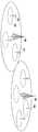
도 3은 단말이 측정한 신호 에너지와 간섭세기에 따라 단말이 채널상태 정보 중 하나인 CQI (Channel Quality Indicator)를 전송하는 것을 도시한 도면이다.
도 4는 복수의 셀로 이루어진 다중셀 이동통신 시스템에 대한 도면이다.
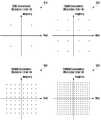
도 5는 QPSK, 16QAM, 64QAM, 256QAM의 성상도(Contstellation)를 도시한 도면이다.
도 6은 상기의 문제점을 설명하기 위하여 단말과 기지국 사이에서 이루어지는 AMC를 보다 구체적으로 도시한 것이다.
도 7은 다수의 기지국(또는 TP(특히 CoMP의 경우에 있어서))들이 256 QAM을 이용하여 데이터를 수신 가능한 특정 사용자 단말기에게 협력 방식을 사용하여 통신 서비스를 제공하는 CoMP 상황에서 데이터를 주고 받는 상황을 도시한 것이다.
도 8은 MCS table 전환방법 1을 이용하여 MCS table 전환이 이루어지는 과정을 기지국 관점에서 각각 도시한 것이다.
도 9는 MCS table 전환방법 1을 이용하여 MCS table 전환이 이루어지는 과정을 단말 관점에서 도시한 것이다.
도 10은 MCS table 전환방법 2를 이용하여 MCS table 전환이 이루어지는 과정을 기지국 관점에서 도시한 것이다.
도 11은 MCS table 전환방법 2를 이용하여 MCS table 전환이 이루어지는 과정을 단말 관점에서 도시한 것이다.
도 12는 MCS table 전환방법 3을 이용하여 MCS table 전환이 이루어지는 과정을 기지국 관점에서 도시한 것이다.
도 13은 MCS table 전환방법 3을 이용하여 MCS table 전환이 이루어지는 과정을 단말 관점에서 도시한 것이다.
도 14는 Fallback 모드 유무에 따라 MCS table 전환방법 3을 이용하여 MCS table 전환이 이루어지는 과정을 기지국 관점에서 도시한 것이다.
도 15는 Fallback 모드 유무에 따라 MCS table 전환방법 3을 이용하여 MCS table 전환이 이루어지는 과정을 단말 관점에서 도시한 것이다.
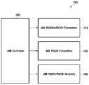
도 16은 본 발명에서 제안하는 CQI 해석방법 및 MCS 정의방법을 구현하기 위한 기지국 송수신기 구조를 도시한 것이다.
도 17은 본 발명에서 제안하는 MCS 해석방법을 구현하기 위한 단말 송수신기 구조를 도시한 것이다.1 is a diagram showing time and frequency resources in an LTE / LTE-A system.
FIG. 2 is a diagram illustrating radio resources of 1 subframe and 1 RB, which are the minimum units that can be downlink-scheduled in the LTE / LTE-A system.
3 is a diagram illustrating that a UE transmits a CQI (Channel Quality Indicator), which is one of channel state information, according to signal energy measured by a UE and interference intensity.
4 is a diagram of a multi-cell mobile communication system composed of a plurality of cells.
5 is a diagram illustrating constellation of QPSK, 16QAM, 64QAM, and 256QAM.
FIG. 6 illustrates the AMC between the UE and the BS in more detail in order to explain the above problem.
7 is a diagram illustrating a situation in which a plurality of base stations (or TPs (in particular, in the case of CoMP)) transmit and receive data in CoMP situations in which communication services are provided to specific user terminals capable of receiving data using 256 QAM, FIG.
FIG. 8 shows the process of switching MCS tables using the MCS
FIG. 9 shows a process of switching an MCS table using the MCS
FIG. 10 shows a process of switching an MCS table using the MCS
FIG. 11 shows a process of switching an MCS table using an MCS
FIG. 12 shows a process of switching an MCS table using the MCS table conversion method 3 from the viewpoint of a base station.
FIG. 13 shows the process of switching the MCS table using the MCS table conversion method 3 from the viewpoint of the terminal.
FIG. 14 shows a process of switching an MCS table using the MCS table switching method 3 according to whether there is a fallback mode from the viewpoint of a base station.
FIG. 15 shows a process of switching the MCS table using the MCS table switching method 3 according to the presence or absence of the fallback mode from the viewpoint of the terminal.
FIG. 16 illustrates a structure of a base station transceiver for implementing the CQI analysis method and the MCS defining method proposed in the present invention.
17 illustrates a structure of a UE transceiver for implementing the MCS analysis method proposed by the present invention.
이하 본 발명의 실시예를 첨부한 도면과 함께 상세히 설명한다. 또한 본 발명을 설명함에 있어서 관련된 공지 기능 혹은 구성에 대한 구체적인 설명이 본 발명의 요지를 불필요하게 흐릴 수 있다고 판단된 경우 그 상세한 설명은 생략한다. 그리고 후술되는 용어들은 본 발명에서의 기능을 고려하여 정의된 용어들로서 이는 사용자, 운용자의 의도 또는 관례 등에 따라 달라질 수 있다. 그러므로 그 정의는 본 명세서 전반에 걸친 내용을 토대로 내려져야 할 것이다.Hereinafter, embodiments of the present invention will be described in detail with reference to the accompanying drawings. In the following description, a detailed description of known functions and configurations incorporated herein will be omitted when it may make the subject matter of the present invention rather unclear. The following terms are defined in consideration of the functions of the present invention, and these may be changed according to the intention of the user, the operator, or the like. Therefore, the definition should be based on the contents throughout this specification.
또한, 본 발명의 실시예들을 구체적으로 설명함에 있어서, OFDM 기반의 무선통신 시스템, 특히 3GPP EUTRA 표준을 주된 대상으로 할 것이지만, 본 발명의 주요한 요지는 유사한 기술적 배경 및 채널형태를 가지는 여타의 통신 시스템에도 본 발명의 범위를 크게 벗어나지 아니하는 범위에서 약간의 변형으로 적용 가능하며, 이는 본 발명의 기술분야에서 숙련된 기술적 지식을 가진 자의 판단으로 가능할 것이다.While the embodiments of the present invention will be described in detail, the OFDM-based wireless communication system, particularly the 3GPP EUTRA standard, will be the main object of the present invention, but the main point of the present invention is to provide a communication system It will be understood by those skilled in the art that various changes in form and details may be made therein without departing from the spirit and scope of the invention as defined by the appended claims.
도 3은 단말이 측정한 신호 에너지와 간섭세기에 따라 단말이 채널상태 정보 중 하나인 CQI (Channel Quality Indicator)를 전송하는 것을 도시한 도면이다.3 is a diagram illustrating that a UE transmits a CQI (Channel Quality Indicator), which is one of channel state information, according to signal energy measured by a UE and interference intensity.
도 3을 참조하면, 단말은 CSI-RS와 같은 하향링크 기준신호를 측정하여 채널추정을 수행하고 이를 이용하여 곡선(300)과 같은 무선채널에 따른 Es (수신신호 에너지)를 산출한다. 또한 단말은 하향링크 기준신호 또는 간섭 및 잡음측정을 위한 별도의 자원을 이용하여 곡선(310)과 같은 간섭 및 잡음의 세기를 산출한다. LTE에서는 간섭 및 잡음측정을 위하여 하향링크 기준신호인 CRS를 이용하거나 간섭측정자원 (Interference Measurement Resource)를 기지국이 단말에게 설정하여 해당 무선자원에서 측정되는 신호를 간섭 및 잡음으로 가정하도록 한다. 이와 같은 방법으로 얻은 수신신호 에너지와 간섭 및 잡음의 세기를 이용하여 단말은 자신이 산출한 해당 신호 대 간섭 및 잡음비에서 일정한 성공율로 수신할 수 있는 최대의 데이터전송 속도를 판단하고 이를 기지국에 통보한다. 단말이 해당 신호 대 간섭 및 잡음비에서 지원할 수 있는 최대의 데이터전송 속도를 통보받은 기지국은 상기 데이터전송 속도를 이용하여 단말에게 전송할 하향링크 데이터 신호의 실제 데이터 전송율을 결정하게 된다. 이와 같이, 단말이 기지국에 자신이 일정한 성공율로 수신할 수 있는 최대의 데이터 전송속도를 LTE 표준에서는 CQI (Channel Quality Indicator)라고 한다. 일반적으로 무선채널은 시간에 따라 변하기 때문에, 단말은 주기적으로 CQI를 기지국에게 통보하거나 기지국에서 단말에게 이를 요청할 때마다 통보하게 된다.Referring to FIG. 3, a UE measures a downlink reference signal such as a CSI-RS to perform channel estimation, and calculates Es (received signal energy) according to a radio channel such as a
도 4는 복수의 셀로 이루어진 다중셀 이동통신 시스템에 대한 도면이다.4 is a diagram of a multi-cell mobile communication system composed of a plurality of cells.
도 4를 참조하면, 다중셀 이동통신 시스템에는 고출력 송신을 수행하는 macro cell과 저출력 송신을 수행하는 small cell이 혼재될 수 있다. 이때 각 셀이 단말에게 송수신을 수행하는 서비스 영역 또는 coverage area는 해당 셀의 송신전력에 따라 달라진다. 한 예로 고출력 신호를 전송하는 송신기 400에 의하여 생성되는 coverage area는 410과 같이 넓은 영역을 가지는 반면에, 저출력 신호흘 전송하는 송신기 420에 의하여 생성되는 coverage area는 430과 같이 좁은 영역을 가지게 된다. 도 4에서와 같이 제한된 영역내에서 혼재하는 macro cell과 small cell은 상호 간섭을 발생시켜 각각의 성능을 저하시키게 되기도 한다. 본 특허에서의 small cell은 별도의 다중셀 시스템에서 별도의 Cell ID를 갖는 셀 및 macro cell과 동일한 cell ID를 가지며 해당 macro cell의 coverage area내에 분산되어 있는 RRH (remote radio head)를 포함한다.Referring to FIG. 4, a macro cell for performing high-power transmission and a small cell for performing low-power transmission may be mixed in the multi-cell mobile communication system. At this time, the service area or coverage area where each cell performs transmission / reception to the UE depends on the transmission power of the corresponding cell. For example, the coverage area generated by the
일반적으로 이동통신 시스템에서 macro cell과 small cell은 서로 다른 용도로 활용된다. Macro cell의 경우 넓은 coverage를 가지는 점을 이용하여 단말의 이동성을 보장하거나 음영지역을 해소하는데 활용된다. 반면 small cell의 경우 인구밀집 지역에 배치되어 제한된 영역에서 높은 속도의 데이터 전송을 수행하는데 활용된다. 특히 small cell의 경우 실내에 배치되는 경우가 많으며 이때 실외에 배치된 macro cell의 신호가 효과적으로 차단되어 매우 높은 신호대 간섭 및 잡음비를 단말이 경험하게 될 수도 있다.Generally, in a mobile communication system, macro cells and small cells are used for different purposes. In case of macro cell, it is used to secure the mobility of the terminal or to solve the shadow area by using the point having a wide coverage. Small cells, on the other hand, are deployed in dense areas and are used to perform high-speed data transmissions in limited areas. Especially, in case of small cell, it is often placed indoors, and at this time, the signal of the macrocell disposed outside can be effectively blocked, so that the terminal may experience a very high signal-to-noise and noise ratio.
상기에서 언급한 바와 같이 LTE와 같은 이동통신 시스템은 채널상태에 따라 적응하여 데이터 전송속도를 결정하는 AMC를 활용하여 시스템 성능을 향상시킨다. AMC는 복수의 변조 방식과 데이터량으로 정의되는 복수의 데이터 전송속도 중에서 단말이 겪는 채널상태를 감안하여 일정한 수신성공율을 유지하며 수신할 수 있는 제일 높은 데이터 전송속도를 골라서 해당 단말에게 전송하는 것이다.As mentioned above, a mobile communication system such as LTE improves the system performance by using an AMC that determines a data transmission rate according to a channel state. The AMC selects a highest data transmission rate that can be received while maintaining a certain reception success rate in consideration of channel conditions experienced by the UE among a plurality of data transmission rates defined by a plurality of modulation schemes and data amounts, and transmits the selected data to the corresponding UE.
표 1은 LTE에서의 AMC에 6RB의 대역폭을 이용하는 하향링크의 데이터 전송속도를 정리한 것이다.Table 1 summarizes the downlink data rate using 6RB bandwidth for AMC in LTE.


표1에는 총 29개의 MCS (Modulation Coding Scheme) level이 정의되어 있으며 각 MCS index는 modulation order와 transport block size로 정의된다. Transport block size라 함은 주어진 대역폭에서 전송되는 정보량의 크기에 해당되며 단위는 비트이다. 즉, 표 1에서 MCS index 28은 총 4392 비트를 6RB (180kHz*6=1080kHz)의 대역폭에서 전송하는 것을 의미한다. Modulation order이라 함은 각 전송되는 변조방식을 적용하였을 때 한 개의 modulation symbol에 실리는 비트수를 의미한다. LTE Release 11와 그 이전 Release에서는 표 1에서와 같이 modulation order 2, 4, 6을 지원한다.A total of 29 Modulation Coding Scheme (MCS) levels are defined in Table 1. Each MCS index is defined as a modulation order and a transport block size. Transport block size refers to the amount of information to be transmitted in a given bandwidth and is in units of bits. That is, in Table 1, the MCS index 28 means that a total of 4392 bits are transmitted in a bandwidth of 6RB (180kHz * 6 = 1080kHz). The modulation order means the number of bits carried in one modulation symbol when each transmitted modulation scheme is applied. LTE Release 11 and earlier releases support
LTE에서 이용하는 modulation order 2, 4, 6외에 추가적으로 도 5의 256QAM을 이용하는 것을 고려할 수 있다. 이와 같이 256QAM을 이용하는 것을 결과적으로 다음의 효과가 있다.In addition to the
더 높은 modulation order를 활용한 더 높은 데이터 전송속도 구현가능Higher data rates can be achieved with higher modulation order
더 많은 modulation order를 활용한 더 넓은 범위의 수신신호 에너지 대 잡음 및 간섭비에 대한 송수신 최적화 가능More modulation orders can be used to optimize transmit and receive for a broader range of receive signal energy versus noise and interference ratios
도 5는 QPSK, 16QAM, 64QAM, 256QAM의 성상도(Contstellation)를 도시한 도면이다.5 is a diagram illustrating constellation of QPSK, 16QAM, 64QAM, and 256QAM.
도 5를 참조하면, LTE Release 11와 그 이전 Release에서는 modulation order 2, 4, 6을 위하여 QPSK(510), 16QAM(520), 64QAM(530)을 이용한 데이터 송수신을 수행한다. 일반적으로 높은 modulation order일 수록 더 많은 데이터를 전송할 수 있다는 장점이 있지만 더 높은 수신신호 에너지 대 잡음 및 간섭비가 요구된다는 단점도 있다. 특히 256QAM(540)의 경우 매우 높은 수신신호 에너지 대 잡음 및 간섭비에서만 충분한 수신성능을 지원할 수 있다. 수신신호 에너지 대 잡음 및 간섭비를 만족시키기 위하여 단말의 수신기의 복잡도가 증가하는 것도 단점이다. 단말의 ADC (Analog to Digital Converter)에서 quantization bit수에 따라 잡음이 발생하게 되는데 이를 억제하기 위해서는 quantization bit수를 증가시켜야 하며 이로 인하여 단말의 추가적인 복잡도 및 전력소모가 불가피하다.Referring to FIG. 5, LTE Release 11 and prior releases perform data transmission /
더 많은 종류의 modulation order를 지원하는 것이 더 넓은 범위의 수신신호 에너지 대 잡음 및 간섭비를 지원할 수 있게 하여 시스템 성능을 향상시킬 수 있는 장점이 존재한다. 즉, modulation order 2, 4만을 지원하는 시스템과 비교하여 modulation order 2, 4, 6을 지원하는 시스템이 더 넓은 범위의 수신신호 에너지 대 잡음 및 간섭비를 지원할 수 있게 되며 이에 따른 성능개선 효과도 기대할 수 있다. LTE 시스템에서 더 많은 종류의 modulation order를 지원하는 것의 문제점으로는 다음의 두 가지가 존재한다.Supporting more types of modulation orders has the advantage of improving system performance by allowing a wider range of received signal energy to noise and interference ratios to be supported. In other words, a system that supports
기지국이 단말에게 하향링크 송신을 통보하는 제어채널의 정보량 증가The base station increases the information amount of the control channel notifying the downlink transmission to the terminal
단말이 기지국에 통보하는 채널상태 정보량 증가The amount of channel state information that the terminal notifies to the base station increases
도 6은 상기의 문제점을 설명하기 위하여 단말과 기지국 사이에서 이루어지는 AMC를 보다 구체적으로 도시한 것이다.FIG. 6 illustrates the AMC between the UE and the BS in more detail in order to explain the above problem.
도 6을 참조하면, 단말은 600에서 기지국이 전송한 하향링크 기준신호인 CSI-RS와 간섭을 측정하는 무선자원인 IMR (Interference Measurement Resource)를 610과 같이 수신하여 이를 이용하여 620과 같이 채널상태 정보를 생성한다. 단말이 생성하는 채널상태 정보에 포함되는 정보로는 CQI가 존재하며 상기 CQI는 단말이 지원할 수 있는 최대 데이터 전송속도를 의미한다. LTE Release 11 시스템에서 상기 CQI는 4 bit의 정보량을 가지며 다음의 표 2와 같이 정의된다.Referring to FIG. 6, the UE receives a CSI-RS, which is a downlink reference signal transmitted from a base station, and an IMR (Interference Measurement Resource), which is a radio resource for measuring interference, Information. CQI exists as information included in channel state information generated by the UE, and the CQI indicates a maximum data transmission rate that the UE can support. In the LTE Release 11 system, the CQI has an information amount of 4 bits and is defined as shown in Table 2 below.
표 2의 LTE Release 11 및 그 이전 Release에 정의된 CQI는 modulation을 64QAM까지만 지원하며 256QAM은 지원하지 않음을 알 수 있다. 즉, 단말은 표 2를 이용할 경우 자신이 실제 256QAM을 지원할 수 있으며 채널상태가 좋아서 256QAM으로 수신된 신호를 요구되는 수신성능으로 복호화 할 수 있더라도 이를 기지국에 통보하는 방법이 없다. 따라서, 256QAM을 지원하기 위해서는 256 QAM을 지원하는 추가적인 CQI table이 필요함을 알 수 있다. 하기 표 3은 256 QAM을 위한 CQI table을 예시한 것이다.The CQI defined in LTE Release 11 and earlier releases in Table 2 supports modulation up to 64 QAM and does not support 256 QAM. That is, when using Table 2, the UE can support 256QAM in practice, and the UE can decode a signal received in 256QAM with a required reception performance because of its good channel condition, but there is no way to notify the base station of the received signal. Therefore, to support 256QAM, an additional CQI table supporting 256 QAM is required. Table 3 below illustrates a CQI table for 256 QAM.
표 3과 같은 CQI table로 단말이 생성하는 채널상태 정보를 이용하여 기지국에 단말이 지원할 수 있는 최대 데이터 전송속도를 알릴 수 있으며, CoMP의 경우 각각의 기지국이 상위 시그널링을 통해 서로 알고 있다는 가정하에 각자 다른 CQI table을 이용하여 CQI를 주고 받고 최대 데이터 전송속도를 파악할 수 있다.It is possible to notify the base station of the maximum data transmission rate that can be supported by the UE using the CQI table generated by the UE using the CQI table shown in Table 3. In the case of CoMP, each base station knows each other through upper signaling, The CQI can be exchanged using another CQI table and the maximum data transmission rate can be grasped.
LTE Release 11에서 256QAM이 지원될 수 없는 또 하나의 이유는 기지국에서 단말에게 데이터 채널인 PDSCH (Physical Downlink Shared Channel)에 대한 스케줄링 정보를 담고 있는 제어채널인 PDCCH/E-PDCCH (Physical Downlink Control Channel/Enhanced Physical Downlink Control Channel)로 단말에게 통보되는 제어정보에 256QAM을 지정할 수 있는 기능이 없기 때문이다. 단말은 PDCCH/E-PDCCH를 복호화하여 여기에 실린 제어정보를 수신함으로써 PDSCH가 자신에게 전송되었는지 여부와 PDSCH가 어떤 modulation 방식으로 전송되었는지를 통보 받는다. 문제는 Release 11에 정의된 제어정보에는 256QAM을 통보하는 기능이 없다는 점이다. 표 1이 LTE/LTE-A Release 11에 정의된 PDSCH의 modulation order 및 정보 비트수를 정리한 것이다. 기지국은 단말에게 표1의 modulation index 값을 통보함으로써, 해당 단말에게 PDSCH의 modulation order 및 정보량의 비트수를 통보하는 것이다. 여기에 256QAM을 지정하는 MCS index가 존재하지 않음을 알 수 있다.Another reason that 256QAM can not be supported in LTE Release 11 is that a base station transmits PDCCH / E-PDCCH (Physical Downlink Control Channel / E-PDCCH), which is a control channel containing scheduling information for a physical downlink shared channel (PDSCH) This is because the control information notified to the UE by the Enhanced Physical Downlink Control Channel does not have a function of designating 256QAM. The UE decodes the PDCCH / E-PDCCH and receives the control information included in the PDCCH / E-PDCCH, thereby notifying the UE whether the PDSCH is transmitted to the UE and the modulation scheme of the PDSCH. The problem is that the control information defined in Release 11 does not have the capability to notify 256QAM. Table 1 summarizes the modulation order and information bit number of the PDSCH defined in LTE / LTE-A Release 11. The base station notifies the UE of the modulation index value of Table 1, thereby notifying the UE of the modulation order of the PDSCH and the number of bits of the information amount. It can be seen that there is no MCS index specifying 256QAM.
한편, 도 4에서 설명한 바와 같은 셀룰라 무선 통신 시스템에서, 셀의 경계 영역에 위치하는 사용자 단말기는 다른 셀로부터의 간섭이 크게 작용하여 높은 데이터 전송률을 지원받는데 한계가 존재한다. 즉, 도 4에서 설명한 바와 같은 셀룰라 무선 통신 시스템에서, 셀 내에 존재하는 사용자 단말기들에게 제공되는 고속의 데이터 서비스의 전송률은 사용자 단말기가 셀 내에서 어디에 위치하느냐에 따라 크게 영향을 받는다. 그러므로, 일반적인 셀룰라 무선 통신 시스템에서는 셀 중앙에서 상대적으로 가까운 곳에 위치한 사용자 단말기와는 비교적 높은 전송률을 사용하여 데이터를 송수신할 수 있지만, 셀 중앙에서 상대적으로 먼 곳에 위치한 사용자 단말기에 대해서는 높은 전송률을 보장하기 어렵다.On the other hand, in a cellular wireless communication system as illustrated in FIG. 4, a user terminal located in a boundary region of a cell has a limitation in that interference from other cells greatly affects and a high data transmission rate is supported. That is, in the cellular wireless communication system as described with reference to FIG. 4, the data rate of the high-speed data service provided to the user terminals existing in the cell is greatly influenced by where the user terminal is located in the cell. Therefore, in a typical cellular wireless communication system, data can be transmitted and received using a relatively high data rate with respect to a user terminal located relatively close to the center of the cell, but a high data rate is guaranteed for a user terminal located relatively far from the center of the cell it's difficult.
이와 같이, 셀 경계 영역에 위치하는 사용자 단말기에게 높은 전송률로 데이터 서비스를 제공하고, 높은 데이터 전송률을 제공하는 서비스 영역을 확대하기 위해 LTE-A 이동 통신 시스템에서는 다수의 셀들이 특정 사용자 단말기에게 협력 방식을 사용하여 통신 서비스를 제공하는 CoMP 방식이 제안된 바 있다.As described above, in order to provide a data service at a high data rate to a user terminal located in a cell boundary area and to expand a service area providing a high data rate, in a LTE-A mobile communication system, A CoMP method has been proposed in which a communication service is provided by using a CoMP.
도 7은 다수의 기지국(또는 TP(특히 CoMP의 경우에 있어서))들이 256 QAM을 이용하여 데이터를 수신 가능한 특정 사용자 단말기에게 협력 방식을 사용하여 통신 서비스를 제공하는 CoMP 상황에서 데이터를 주고 받는 상황을 도시한 것이다.7 is a diagram illustrating a situation in which a plurality of base stations (or TPs (in particular, in the case of CoMP)) transmit and receive data in CoMP situations in which communication services are provided to specific user terminals capable of receiving data using 256 QAM, FIG.
도 7을 참조하면, 단말은 복수개의 TP로부터 PDSCH를 수신하게 된다. CoMP 전송과 일반적인 non-CoMP 전송의 차이는 상위 시그널링에 의한 handover 없이 단말이 복수개의 TP중 어느 한 TP에서 PDSCH를 수신할 수 있다는 점이다. 일반적으로 CoMP가 지원되지 않는 시스템에서는 한 기지국에서 PDSCH를 수신하던 단말은 다른 기지국에서 PDSCH를 수신하기 위한 상위 시그널링이 동반된 handover과정이 필수적이다. 이러한 handover과정은 시간이 소요되며 실패 가능성이 존재한다. 반면 도 7에서의 경우 단말은 복수개의 TP 중 한군데서 신호를 수신하다가 상위 시그널링을 동반한 handover 없이 복수개의 TP 중 다른 곳에서 신호를 수신할 수 있다. 이는 CoMP가 가능한 시스템의 경우 복수의 셀들의 송수신을 제어하는 중앙집중형 제어기가 존재하기 때문에 가능하다.Referring to FIG. 7, the UE receives a PDSCH from a plurality of TPs. The difference between CoMP transmission and general non-CoMP transmission is that a mobile station can receive a PDSCH from any one of a plurality of TPs without handover by higher signaling. Generally, in a system where CoMP is not supported, a handover process involving higher signaling for receiving a PDSCH from another base station is indispensable for a UE that has received a PDSCH from one base station. This handover process is time consuming and there is a possibility of failure. On the other hand, in FIG. 7, the terminal receives a signal from one of the plurality of TPs, and can receive the signal from the other of the plurality of TPs without a handover accompanied by the higher signaling. This is possible because there is a centralized controller that controls the transmission and reception of a plurality of cells in the case of a CoMP capable system.
이와 같이 동시에 복수개의 TP에서 전송되는 신호를 수신하는 경우에는, 각 TP에서 전송되는 CRS 및 control channel을 고려하여 PDSCH를 전송해야 한다. 한 예로 도 7에서 단말은 각 TP의 CRS 및 control channel용 무선자원들을 제외한 나머지 부분에서 PDSCH를 수신한다.When a signal transmitted from a plurality of TPs is received at the same time, the PDSCH must be transmitted considering the CRS and the control channel transmitted from each TP. For example, in FIG. 7, the UE receives the PDSCH in the remaining part except for the CRS of each TP and the radio resources for the control channel.
일반적으로 하향링크에서 단말이 PDSCH 신호를 수신하고 거기에 실린 데이터를 복원하기 위해서는 PDSCH가 전송되는데 이용된 무선자원을 정확히 알고 있어야 한다. 어느 주파수 및 시간 자원에 PDSCH가 전송되는지를 모를 경우 단말은 PDSCH에 실린 데이터를 성공적으로 복원시킬 수 없다. 때문에 도 7에서와 같이 CoMP 전송을 수신하는 단말은 각 TP에서 사용 가능한 무선자원을 정확히 파악하고 이를 이용하여 PDSCH가 전송될 수 있는 무선자원을 판단하는 것이 필요하다.Generally, in order to receive a PDSCH signal in the downlink and recover the data stored in the PDSCH, the PDSCH must know the radio resource used to transmit the PDSCH. If the UE does not know to which frequency and time resources the PDSCH is transmitted, the UE can not successfully restore the data on the PDSCH. Therefore, as shown in FIG. 7, the UE receiving the CoMP transmission needs to accurately grasp the available radio resources in each TP and determine the radio resources to which the PDSCH can be transmitted by using the received radio resources.
CoMP 시스템에서는 CoMP 전송을 수행하는 TP들을 사전에 결정한 후 이를 상위 시그널링을 이용하여 단말에게 통보하고 나서 CoMP 전송을 수행한다. 이때 CoMP 전송을 수행하는 것으로 한번 결정된 TP들은 다음 상위 시그널링에 의하여 변경되기 전까지는 계속 CoMP 전송에 참여하게 된다. 이와 같은 상위 시그널링에 의존한 CoMP 전송에 참여하는 TP들의 결정 및 통보는 단말에게 어떤 TP가 CoMP 전송에 참여하는지를 통보함으로서 PDSCH가 어떤 무선자원을 이용하여 전송되는지를 판단할 수 있다.In the CoMP system, TPs that perform CoMP transmission are determined in advance, and then notified to the UE using upper signaling, and then CoMP transmission is performed. At this time, the TPs decided once to perform the CoMP transmission continue to participate in the CoMP transmission until they are changed by the next higher signaling. The determination and notification of the TPs participating in the CoMP transmission depending on the upper signaling can determine which TPs are transmitted using the PDSCH by notifying the UE which TP participates in the CoMP transmission.
도 7에서와 같이 CoMP 방식으로 신호를 주고 받는 상황에서 256 QAM 지원이 가능한 기지국들은 각각 다음과 같이 동작할 수 있다.As shown in FIG. 7, the base stations capable of supporting 256 QAM can operate as follows in the case of exchanging signals in the CoMP scheme.
256 QAM 지원 불가 및 64 QAM 으로 동작Works with 256 QAM not supported and 64 QAM
256 QAM 지원 가능 및 64 QAM 으로 동작Supports 256 QAM and 64 QAM
256 QAM 지원 가능 및 256 QAM 으로 동작Supports 256 QAM and operates with 256 QAM
이에 따라 협력 통신시에 256 QAM을 사용하는 상황에서는 상기에서 언급한 바와 같이 기지국이 단말에게 데이터 채널인 PDSCH에 대한 스케줄링 정보를 담고 있는 제어채널 PDCCH/E-PDCCH에 단말에게 통보되는 제어정보에 256QAM을 지정하여야 할 뿐 아니라 어느 기지국이 64QAM을 사용하여 단말에게 데이터를 송신하였고 어느 기지국은 256QAM을 사용하여 단말에게 데이터를 송신하였는지를 구분 할 수 있어야 한다. 하지만, LTE Release 11에서는 PDCCH/E-PDCCH에 이러한 기능은 존재하지 않는다. 따라서, 협력 통신 상황에서는 단말에게 MCS index 뿐만 아니라 어느 기지국이 256QAM을 사용하였는지에 대하여 통보하는 기능 또한 존재하지 않음을 확인할 수 있다.Accordingly, in the case of using 256 QAM in cooperation communication, as described above, the base station transmits control information notified to the UE on the control channel PDCCH / E-PDCCH containing scheduling information for PDSCH, which is a data channel, In addition, a base station must transmit data to the UE using 64QAM, and a base station should be able to distinguish whether it has transmitted data to the UE using 256QAM. However, in LTE Release 11, this function does not exist in the PDCCH / E-PDCCH. Therefore, in the cooperative communication situation, it can be confirmed that not only the MCS index, but also the function of notifying the base station which 256QAM is used does not exist.
상기에서 언급한 바와 같이 CoMP를 지원하는 LTE/LTE-A 시스템에서 하향링크에서 256QAM을 지원하기 위해서는 MCS를 새롭게 정의해야 한다. 256QAM을 지원하기 위하여 MCS를 새롭게 정의하는 방법으로는 다음의 세가지가 있다.As described above, in order to support 256QAM in downlink in an LTE / LTE-A system supporting CoMP, MCS must be newly defined. There are three methods to newly define MCS to support 256QAM.
새로운 MCS 정의방법 1: MCS의 5bit가 지정하는 spectral efficiency를 확대함New MCS definition method 1: Expansion of spectral efficiency specified by 5bit of MCS
새로운 MCS 정의방법 2: MCS 정보량을 기존 5 bit에서 6 bit로 확대 하여 256QAM까지 지원할 수 있도록 함New MCS definition method 2: Enlarge MCS information from existing 5 bits to 6 bits to support 256QAM
새로운 MCS 정의 방법 3: MCS가 지시하는 spectral efficiency의 range를 가변적으로 운용하여 256QAM까지 지원할 수 있도록 함New MCS definition method 3: Variable range of spectral efficiency indicated by MCS allows to support up to 256QAM
본 발명에서 제안하는 MCS 정의방법 1은 종래의 MCS와 마찬가지로 5 bit를 사용하되 MCS가 256QAM까지 지정할 수 있도록 하는 방법이다. 결과적으로 이 방법에서는 256QAM을 지정하기 위하여 기존의 MCS 정의방법과 비교하여 MCS index 간 TBS(Transport Block Size)를 덜 촘촘하게 지정하게 되고 이에 따라 운용할 수 있는 spectral efficiency의 가짓수가 줄어들어 시스템의 성능이 저하되게 된다. 다음의 표 4는 MCS 정의방법 1을 적용하여 새롭게 정의한 MCS table이다.The


표 4와 표 1을 비교하면 표 4는 표 1의 modulation order를 통보하는 MCS index 중 일부를 제외시킨 후 256QAM을 지정하는 열한 개의 MCS index가 추가되었음을 알 수 있다. 방법 1은 5 bit를 이용하여 256QAM까지 단말이 기지국에게 통보할 수 있다는 장점이 존재하지만 MCS index들이 지정하는 TBS 간의 크기 차이가 증가함에 따라 최적의 modulation 및 TBS로 시스템을 운용하기 어려워져 시스템의 성능이 상대적으로 감소한다는 단점이 있다. 상기 MCS 정의방법 1은 상위 계층 시그널링에 의하여 그 적용여부가 단말에게 통보될 수 있다. 즉, 기지국이 256QAM을 송신할 수 있는 기능이 구현되어 있으며 단말 또한 256QAM을 수신할 수 있는 기능이 구현되어 있다고 판단할 경우 기지국이 단말에게 상위 계층 시그널링으로 상기 MCS 정의방법 1을 적용하라고 통보하는 것이다. 반대로 기지국이 단말에게 상위계층 시그널링을 이용하여 상기 MCS 정의방법 1에서 종래의 MCS 정의방법으로 전환하라고 통보할 수도 있다.Table 4 compares Table 1 with Table 1. Table 4 shows that MCS indices for the modulation order shown in Table 1 are excluded, and then eleven MCS indexes are designated to specify 256QAM. The
본 발명에서 제안하는 MCS 정의방법 2는 MCS의 정보량을 5 bit에서 6 bit로 확대하는 것이다. 다음의 표 5는 MCS 정의방법 2를 적용하여 새롭게 정의한 MCS table이다.The


표 5와 표 1을 비교하면, 표 5는 표 1의 modulation order를 통보하는 MCS index 에 더하여 256QAM을 지정하는 31개의 MCS index를 추가되었음을 알 수 있다. 이 경우 MCS가 지정할 수 있는 index가 총 64개가 되기 때문에 상기 방법 1과 비교하여 modulation 및 TBS 정보의 촘촘함이 감소하는 단점 없이 256QAM을 지원할 수 있다. 반면 상기 방법 2의 단점은 기존의 MCS와 비교하여 추가적으로 데이터 채널인 PDSCH에 대한 스케줄링 정보를 담고 있는 제어채널 PDCCH/E-PDCCH에 1 bit의 정보량이 필요하다는 점이다. 즉, 단말이 방법 2를 지원하기 위해서는 기존의 5 bit MCS 대신 6 bit MCS를 제어 채널을 통해 수신 받아야 하기 때문에 추가적인 제어채널 오버헤드 사용 및 DCI (Downlink Control Information) bit 구조 변경이 불가피하다. 이러한 제어정보량이 증가에 따라 성능이 저하되거나 추가적인 전송 에너지를 할당해야 이전과 동일한 성능을 낼 수 있다.Table 5 compares Table 1 with 31 MCS indexes specifying 256QAM in addition to the MCS index notifying the modulation order of Table 1. In this case, the total number of indexes that can be designated by the MCS is 64, so that 256QAM can be supported without disadvantage that the compactness of modulation and TBS information is reduced compared with the
본 발명에서 제안하는 MCS 정의방법 3은 단말이 MCS의 정보량을 5 bit로 기존과 동일하게 유지하되 해당 5 bit의 MCS가 가리키는 범위를 상황에 따라 적응적으로 변경하는 것이다. 방법 3에서는 기본적으로 두 개의 MCS table을 운용한다. 두 개의 MCS table 중 첫 번째는 256QAM을 지정할 수 없는 표 1의 종래의 MCS table이다. 두 개의 MCS table 중 두 번째는 256QAM을 지정할 수 있는 다음과 같은 MCS table이다. 하기 표 6은 MCS 정의방법3에서 256QAM 지정을 위한 MCS table을 예시한 것이다.In the MCS definition method 3 proposed by the present invention, the terminal keeps the information amount of the MCS equal to 5 bits, and adaptively changes the range indicated by the 5-bit MCS according to the situation. Method 3 basically operates two MCS tables. The first of the two MCS tables is the conventional MCS table of Table 1 in which 256QAM can not be specified. The second of the two MCS tables is the following MCS table, which can specify 256QAM. Table 6 below illustrates an MCS table for 256QAM designation in MCS definition method 3.


표 6의 MCS table는 MCS index 4, …, 27에서 256QAM을 가정하는 spectral efficiency를 지원하도록 설계되어 있다. 표 6에서 X0, …, X23은 256QAM을 적용하였을 때를 위한 TBS 크기이며 R0, …, R23는 256QAM을 적용하였을 때의 spectral efficiency이다. 일반적으로 256QAM을 지원할 경우 64QAM을 지원할 때보다 spectral efficiency가 높아진다. 256QAM을 이용할 때의 MCS 정보를 통보하기 위하여 일부 표 1의 QPSK, 16QAM, 64QAM을 위한 낮은 modulation order들을 지정하는 MCS index들이 제외되었다. 이와 같이 표 1의 MCS table과 표 6의 MCS table을 적응적으로 변경하며 이용할 경우 단말은 어떤 MCS table을 이용하느냐에 따라 기지국으로부터 받은 데이터 채널인 PDSCH를 복호화 할 modulation order가 달라지게 된다. 즉, 단말이 표 1의 MCS table을 이용할 경우 낮은 영역의 modulation order를 이용하여 기지국으로부터 받은 데이터를 복호화 할 수 있지만 256QAM에 대응되는 높은 영역의 modulation order를 이용하여 복호화 할 수는 없다.The MCS table in Table 6 shows
상기 MCS 정의방법 3의 장점은 5 bit의 MCS를 이용하여 256QAM을 지원할 수 있으면서 상기 MCS 정의방법 1과 달리 상대적으로 시스템의 성능을 떨어뜨리는 문제점이 없다는 것이다. 반면 MCS 정의방법 3은 상기 MCS 정의방법 1 또는 MCS 정의방법 2와 달리 단말이 데이터를 전송 받는 각각의 기지국들이 두 개의 MCS table 중 어느 MCS table을 사용하여 데이터를 전송하고 있는 지를 알려주는 방법이 추가로 도입되어야 한다. 본 발명에서는 기지국 별로 단말에게 두 개의 MCS table 중 하나의 MCS table을 사용하여 데이터를 복호화 하는 방법으로 다음의 세가지 방법을 제안한다.The advantage of the MCS defining method 3 is that it can support 256QAM using a 5-bit MCS, but unlike the
MCS table 전환방법 1: 상위 계층 시그널링을 이용하여 단말 별로 MCS table을 전환하는 방법MCS table switching method 1: Switching MCS table for each terminal using upper layer signaling
MCS table 전환방법 2: CSI-Process (Channel Status Information Process)의 CQI table 설정을 이용하여 단말 별로 MCS table을 전환하는 방법MCS table switching method 2: Switching MCS table by terminal using CQI table setting of CSI-Process (Channel Status Information Process)
MCS table 전환방법 3: 제어채널 PDCCH/E-PDCCH의 제어 정보에 포함되는 PQI (PDSCH RE Mapping and Quasi-Co-Location Indicator)를 이용하여 TP 별로 dynamic하게 전환하는 방법MCS table switching method 3: Dynamically switching by TP using the PQI (PDSCH RE Mapping and Quasi-Co-Location Indicator) included in the control information of the control channel PDCCH / E-PDCCH
본 발명에서 제안하는 MCS table 전환방법 1은 상위계층 시그널링을 이용하여 이루어진다. 이 방법에서는 단말이 처음에는 표 1의 MCS table을 이용하고 있다가 단말의 CQI report를 이용하여 자신의 하향링크 채널상태를 측정한 결과 256QAM을 지원할 수 있다고 판단될 때 이를 기지국에게 상위 시그널링을 이용하여 통보한다. 여기서 기지국은 단말의 CQI report가 256QAM에 해당할 경우 이를 다른 단말 및 네트워크의 데이터를 이용하여 판단하여 단말에게 표 6의 MCS table을 사용하게 지시할 수도 있으며, 단말의 CQI report만을 이용하여 MCS table의 전환여부를 결정할 수도 있다.The MCS
일반적으로 상위계층 시그널링은 물리계층 시그널링과 비교하여 송신 및 수신과정에 추가적인 시간 지연이 발생하며, 협력 통신의 경우 다양한 기지국들이 256QAM을 지원 여부를 결정하기 때문에, 상위계층 시그널링을 이용하여 단말 별로 전환할 경우 상기에서 언급한 MCS 정의방법 1과 마찬가지로 상황에 따라 성능의 저하가 발생할 수 있다.Generally, the higher layer signaling is compared with the physical layer signaling, and additional time delay occurs in the transmission and reception processes. In the case of cooperative communication, various base stations determine whether to support 256QAM. Therefore, The performance may be degraded depending on the situation as in the
본 발명에서 제안하는 MCS table 전환방법 2는 CSI-Process의 CQI table 상태를 이용하여 이루어진다. LTE Release 11 에서 CoMP가 가능한 시스템은 복수의 TP들의 송수신을 제어하는 중앙집중형 제어기를 통해서 단말에 CSI-Process를 설정한다. 이러한 CSI-process들을 이용하여 협력 통신을 통해 단말은 하향링크 데이터를 받는 기지국들과의 무선 채널에 대한 CQI 등의 무선 채널 상태 리포트를 4개까지 지원한다. 단말은 기지국이 설정한 각 CSI-Process에 따라 기지국과 약속 된 방법으로 지정된 CSI-RS에 해당하는 채널에 대하여 기지국에 채널 상태 정보를 송신한다. 이 때, 기지국은 중앙집중형 제어기의 알림에 따라 해당 단말의 CSI-process들이 어떠한 CQI table (64QAM 혹은 256QAM 기반의 MCS table)을 사용하고 있는 지 파악할 수 있으며, 단말은 스스로가 각각의 기지국에 올리는 CSI-Process 별로 가능한 최대 데이터 전송률을 올리는 데에 사용되고 있는 CQI table 정보를 알 수 있다. 따라서, 기지국과 단말은 각각의 CSI-process에 설정된 CQI table 정보를 이용하여 기지국과의 약속 하에 현재 사용되는 MCS table을 사전에 정의된 방법으로 전환 할 수 있다. 본 발명에서는 CSI-Process 별로 주어지는 CQI table 정보를 이용하여 단말에게 두 개의 MCS table 중 하나의 MCS table을 사용하여 데이터를 복호화 하는 방법으로 다음의 세가지 방법을 제안한다.The MCS
CSI-Process별 MCS table 전환방법 1: 64 QAM 기반 CQI table을 사용하는 process가 하나라도 존재할 경우 표 1의 64 QAM MCS Table 선택하는 방법Switching to MCS table by CSI-Process Method 1: When there is any process using 64 QAM-based CQI table, select 64 QAM MCS Table in Table 1
CSI-Process별 MCS table 전환방법 2: 256 QAM 기반 CQI table을 사용하는 process가 절반 이상일 경우 표 6의 256 QAM MCS Table 선택하는 방법Switching to MCS table by CSI-process Method 2: Selecting 256 QAM MCS Table in Table 6 when the process using 256 QAM-based CQI table is more than half
CSI-Process별 MCS table 전환방법 3: 256 QAM 기반 CQI table을 사용하는 process가 하나라도 존재할 경우 256 QAM MCS Table 선택하는 방법Switching MCS table by CSI-process Method 3: Selecting 256 QAM MCS table when there is a process using 256 QAM-based CQI table
다음의 표 7은 도 7 에 나타난 예시 중 세 개의 기지국이 단말에게 하향 링크 데이터를 전송하는 상황을 가정하여 CSI-Process별 MCS table 전환방법마다 선택하는 MCS table을 예시한 것이다.The following Table 7 illustrates an MCS table for each CSI-Process MCS table switching method, assuming that three base stations transmit downlink data to the UE in the example shown in FIG.
한 편, 각 CSI-Process별 MCS table 전환 방법에 따라 유리한 MCS table 구성이 존재한다. CSI-Process별 전환방법 1의 경우 CSI-Process 중 하나의 process 만이라도 64 QAM을 사용할 경우 64 QAM MCS table을 사용하는 방식으로 64 QAM MCS table을 사용한다고 하더라도, 256 QAM에 해당하는 CQI table을 사용하는 process 들이 최대 3개까지 존재 가능하다. 따라서, 64 QAM table 이라고 하더라도 표 4와 같이 256 QAM에 해당하는 modulation 및 TB 크기에 대한 고려가 상대적으로 많이 필요하다. 반면, 256 QAM MCS table을 사용하는 경우에는 모든 CSI-Process 들이 256 QAM 기반 CQI table을 이용하여 채널 정보를 계산하는 상태이다. 따라서, 64 QAM에 해당하는 modulation 및 TB 크기에 대한 고려는 전혀 필요치 않으며, 표 5와 같이 거의 모든 MCS index가 256 QAM 만을 고려한 table을 사용하는 것이 가능하여 상대적으로 256 QAM을 많이 사용하는 상황에 최적화 하기 유리하다.On the other hand, there is an advantageous MCS table structure according to the conversion method of each MCS table for each CSI-process. In case of the
CSI-Process별 전환방법 2의 경우 CSI-Process 중 과반수 이상의 process가 64 QAM을 사용할 경우 64 QAM을 선택하고 반대일 경우 256 QAM MCS table을 사용하는 방식이다. 따라서, 64 QAM MCS table을 사용한다고 하더라도, 256 QAM에 해당하는 CQI table을 사용하는 process 들이 어느 정도 존재 가능하며, 256 QAM MCS table을 사용하는 경우에도 마찬가지 이다. 이에 따라, 64 QAM 및 256 QAM MCS table 모두 반대쪽 modulation에 대한 고려가 필요하다. 다음의 표 8과 표 9는 이러한 경우의 MCS table을 예시한 것이다. 표 1는 CSI-Process별 CQI table 사용 현황에 따른 MCS table 전환 방법 2의 경우 64 QAM MCS table 예시이고, 표 2는 CSI-Process별 CQI table 사용 현황에 따른 MCS table 전환 방법 2의 경우 256 QAM MCS table 예시이다.In the case of the


표 8과 표 9의 64 QAM 및 256 QAM MCS table과 표 1과 표 6의 64 QAM 및 256 QAM MCS table과 비교하여 보면 상대적으로 표 8과 표 9에 반대 쪽 modulation 및 TB size를 지정하는 index 들이 더 많음을 확인할 수 있다.Compared with the 64 QAM and 256 QAM MCS tables of Table 8 and Table 9 and the 64 QAM and 256 QAM MCS tables of Table 1 and Table 6, the indexes that specify the opposite modulation and TB size in Table 8 and Table 9, respectively, And more.
CSI-Process별 전환방법 3의 경우 CSI-Process 중 하나의 process 만이라도 256 QAM을 사용할 경우 256 QAM MCS table을 사용하는 방식으로 64 QAM MCS table을 사용하는 경우에는 모든 CSI-Process 들이 64 QAM 기반 CQI table을 이용하여 채널 정보를 계산하는 상태이다. 따라서, 256 QAM에 해당하는 modulation 및 TB 크기에 대한 고려는 전혀 필요치 않으며, 표 1과 같이 모든 MCS index가 64 QAM 만을 고려한 table을 사용하는 것이 가능하여 64 QAM을 사용할 때에는 현재 사용하는 LTE Release 11과 동일하게 사용가능 하여 상대적으로 64 QAM을 많이 사용하는 상황에 최적화 하기 유리하다. 반면, 256 QAM MCS table을 사용하는 경우에는 64 QAM에 해당하는 CQI table을 사용하는 process 들이 최대 3개까지 존재 가능하다. 따라서, 256 QAM table 이라고 하더라도 표 4와 같이 64 QAM에 해당하는 modulation 및 TB 크기에 대한 고려가 상대적으로 많이 필요하다.In case of switching method 3 according to CSI-process, only one process of CSI-process uses 256 QAM. When using 64 QAM MCS table, all CSI-processes use 64 QAM MCS table. To calculate channel information. Therefore, it is not necessary to consider modulation and TB size corresponding to 256 QAM. As shown in Table 1, it is possible to use a table in which all MCS indices consider only 64 QAM. Therefore, when using 64 QAM, It is advantageous to optimize the situation in which 64 QAM is used comparatively because it is equally usable. On the other hand, when using a 256 QAM MCS table, up to three processes using a CQI table corresponding to 64 QAM can exist. Therefore, even if a 256-QAM table is used, the modulation and the TB size corresponding to 64 QAM are considered to be relatively large as shown in Table 4.
본 발명에서 제안하는 MCS table 전환방법 3은 제어채널 PDCCH/E-PDCCH의 DCI (Downlink Control Information) 정보에 포함되는 PQI field를 이용하여 TP 별로 dynamic하게 전환하는 방법이다. 다음의 표 10은 LTE Release 11 에서 지원하는 PQI Index에 대한 설명이다.The MCS table switching method 3 proposed in the present invention is a method of dynamically switching by TP using the PQI field included in the DCI (Downlink Control Information) information of the control channel PDCCH / E-PDCCH. Table 10 below describes the PQI Index supported by LTE Release 11.
표 10와 같이 단말은 DCI 안의 2 bit의 PQI index를 이용하여 더 높은 계층에서 4 가지의 field를 지정할 수 있으며, 이는 하기 표 11과 같이 더 높은 계층의 파라미터 셋에 대응한다. 다음의 표 11은 PDSCH 맵핑 및 PQI를 통해 지정되는 QCL (Quasi-Colocation) 파라미터 셋의 예시이다.As shown in Table 10, the UE can specify four fields in a higher layer using a 2-bit PQI index in the DCI, which corresponds to a higher layer parameter set as shown in Table 11 below. Table 11 below is an example of a QCAS (Quasi-Colocation) parameter set specified through PDSCH mapping and PQI.
1, 2, 또는 4의 정수값, 및 이에 첨부된 Rel-11 UE 동작을 하지 않는 예비된 값.
디폴트 값은 서빙 셀의 CRS 포트의 수.Number of CRS ports.
An integer value of 1, 2, or 4, and a pre-assigned value that does not make the Rel-11 UE operation attached to it.
The default value is the number of CRS ports in the serving cell.
[0, 5]의 범위에 있는 정수값.
case RAN2에서 디폴트 값은 서빙 셀의 CRS에 대한 주파수 영역 내 위치를 지정(specify)할 것을 결정.Location in the frequency domain for CRS.
An integer value in the range [0, 5].
case In RAN2, the default value is to specify the location in the frequency domain for the serving cell's CRS.
디폴트 값은 서빙 셀의 MBSFN 구성.MBSFN subframe configuration.
The default value is the MBSFN configuration of the serving cell.
세트 {예비된 값 1,2,3,4 (4는 10PRB 이하의 시스템 BW에 대해서만 적용가능하다), 비-교차 반송파 스케줄링의 경우에 서빙 셀의 PCFICH에 의해 지시된 값 또는 교차 반송파 스케줄링의 경우에 더 높은 계층으로 구성된 값} 내에 있는 하나의 값.
디폴트 값은 비-교차-스케줄링의 경우에 서빙 셀의 PCFICH에 의해 지시된 PDSCH의 시작 위치이거나 또는 교차 반송파 스케줄링의 경우에 더 높은 계층으로 구성.PDSCH start symbol.
Set {reserved
The default value is the start position of the PDSCH indicated by the PCFICH of the serving cell in the case of non-cross-scheduling, or a higher layer in the case of cross-carrier scheduling.
디폴트 값은 TM10에서 폴백 DCI 포맷 1A로 스케줄링될 때 UE가 PDSCH 레이트 매칭 및 RE 맵핑을 위해 가정한 ZP CSI-RS 구성.The ZP CSI-RS configuration assumed by the UE for PDSCH rate matching and RE mapping, as determined by zeroTxPowerResourceConfigList and zeroTxPowerSubframeConfig.
The default value is the ZP CSI-RS configuration assumed by the UE for PDSCH rate matching and RE mapping when scheduled in fallback DCI format 1A in TM10.
이러한 파라미터 셋에 64 QAM MCS table을 사용할 것인지 256 QAM MCS table을 사용할 것인지를 알려주는 field를 추가하여 해당 PDSCH RE 들이 64 QAM 혹은 256 QAM MCS table이 지원하는 modulation을 사용하여 복조화 되도록 할 수 있다. 또한, MCS table 전환방법 3은 전환방법 1과 2와 달리 PDCCH/ePDCCH를 이용하여 DCI를 받을 때 마다 MCS table을 전환할 수 있기 때문에, 무선 채널 링크의 상태가 변함에 따라 빠르게 적용될 수 있으며, 기존의 PQI가 지정하는 QCL 파라미터 셋을 이용함으로써 추가적인 성능 저하 및 전송 에너지 할당을 최소화 할 수 있다.The PDSCH REs can be demodulated using 64 QAM or 256 QAM MCS table modulation by adding a field to indicate whether to use the 64 QAM MCS table or the 256 QAM MCS table in these parameter sets. In addition, since the MCS table conversion method 3 can switch the MCS table every time the DCI is received using the PDCCH / ePDCCH unlike the
LTE 시스템에서 단말은 기지국이 지정하는 transmission mode를 지원하도록 되어 있다. Release 11 LTE 시스템에서는 총 10개의 transmission mode가 지원되며 각각의 transmission mode는 하향링크에서 다중안테나를 어떻게 활용하여 PDSCH를 전송하느냐에 따라 차이를 갖는다. 한 예로 transmission mode 9은 최대 8개의 송신안테나를 이용한 PDSCH의 MIMO 전송을 지원하며 transmission mode 2는 최대 4개의 송신안테나를 이용한 PDSCH의 전송다이버시티 전송을 지원한다. 단말 별로 transmission mode는 따로 지정되며 transmission mode에 따라 단말이 수신해야 하는 제어정보의 형식이 달라진다. 이와 같은 transmission mode와 별로도 LTE/LTE-A 시스템에는 fallback transmission도 지원한다. 상기 fallback transmission은 채널상태가 좋지 못한 단말에게 데이터를 전송하기 위하여 고안된 것이다. 한 예로 transmission mode에 따른 하향링크 송신 방법이 단말의 채널상태에 적합하지 않을 경우 기지국은 fallback transmission을 이용하여 단말의 transmission mode를 보다 적합한 것으로 변경해 준다. 또한 fallback transmission은 단말의 설정을 변경하는 구간에서 단말과 기지국 사이에 안정적인 통신기능을 유지시켜주는 역할도 한다. 한 예로 기지국이 transmission mode를 상위계층 시그널링을 이용하여 변경할 경우 기지국에서 상위계층 시그널링을 전송한 후에 단말에 실제 적용되었다고 확신이 들기까지는 시간이 소요된다. 상기 시간구간에서 단말이 스스로 어떤 transmission mode라고 판단하고 있는지 기지국에서 판단할 수 없게 된다. 이와 같은 시간구간에서 fallback transmission을 이용함으로써 기지국에서 단말에게 하향링크 데이터를 전송할 수 있게 한다.In the LTE system, the terminal is designed to support the transmission mode designated by the base station. A total of 10 transmission modes are supported in Release 11 LTE system, and each transmission mode differs according to how PDSCH is transmitted using multiple antennas in downlink. For example, transmission mode 9 supports MIMO transmission of PDSCH using up to 8 transmit antennas, and
상기에서 언급한 바와 같이 기지국이 단말에게 설정된 transmission mode에 따라 PDSCH를 송신할 때와 fallback transmission에 따라 PDSCH를 송신할 때에 서로 다른 DCI format을 이용한다. DCI format이라 함은 LTE에서 제어채널 PDCCH/E-PDCCH내에 제어정보가 구성된 형식을 의미한다. 한 예로 transmission mode 10은 DCI format 2D를 이용한다. 반면 fallback transmission은 DCI format 1A를 이용한다. 단말은 DCI format을 구분함으로써 자신에게 전송된 PDSCH가 transmission mode에 따른 전송인지 아니면 fallback transmission에 따른 전송인지를 판단할 수 있다.As described above, the base station uses different DCI formats when transmitting the PDSCH according to the transmission mode set to the UE and when transmitting the PDSCH according to the fallback transmission. DCI format means a format in which control information is configured in the control channel PDCCH / E-PDCCH in LTE. For example, transmission mode 10 uses DCI format 2D. Fallback transmission, on the other hand, uses DCI format 1A. The UE can determine whether the PDSCH transmitted to the UE is a transmission according to a transmission mode or a transmission due to a fallback transmission by discriminating the DCI format.
본 발명에서는 단말이 MCS index를 해석하는 방법을 단말이 수신한 PDSCH가 fallback transmission인지 아니면 transmission mode에 다른 전송인지에 따라 다르게 적용하는 것을 제안한다. 즉, 단말은 PDSCH가 fallback transmission에 의하여 이루어졌는지 아니면 transmission mode에 따라 이루어졌는지를 판단하고 이에 따라 다른 MCS table을 사용할 수 있다. Fallback transmission의 경우 이를 정리하면 다음과 같다.According to the present invention, it is proposed that the terminal interprets the MCS index according to whether the PDSCH received by the UE is a fallback transmission or a different transmission in the transmission mode. That is, the UE can determine whether PDSCH is performed by fallback transmission or transmission mode, and can use another MCS table accordingly. In the case of a fallback transmission, the following is summarized.
Fallback transmission의 MCS table 전환방법 1: 64 QAM MCS Table을 선택하는 방법Switching MCS table for Fallback transmission Method 1: How to select 64 QAM MCS Table
Fallback transmission의 MCS table 전환방법 2: DCI Format 1A는 기본적으로 PQI field의 상위 QCL 파라미터 셋 중 ‘00’ 에 해당하는 파라미터 셋 1을 지원하므로, 이 파라미터 셋에 담긴 내용에 따라 64 QAM 혹은 256 QAM MCS Table을 선택한다.Switching MCS table of Fallback transmission Method 2: DCI Format 1A basically supports parameter set 1 corresponding to '00' among the upper QCL parameter set of PQI field, so 64 QAM or 256 QAM MCS Select Table.
Fallback transmission이 아닌 transmission mode 10에 의한 하향 링크 제어 정보 포맷 2D의 사용일 경우 다음과 같다.The use of 2D downlink control information format 2D by transmission mode 10 instead of fallback transmission is as follows.
DCI Format 2D의 MCS table 전환방법 1: DCI Format 2D는 DCI에 포함된 PQI field가 표 10와 같이 지정하는 상위 QCL 파라미터 셋을 지원하므로, 이 파라미터 셋에 표 11과 담긴 내용에 추가적으로 MCS table을 지정하는 field를 추가하여 이 field에 포함 된 내용에 따라 64 QAM 혹은 256 QAM MCS Table을 선택한다.DCI Format 2D MCS table conversion method 1: DCI Format 2D supports the upper QCL parameter set specified in Table 10 as the PQI field included in the DCI. Therefore, an MCS table is additionally assigned to this parameter set in addition to Table 11 Field to add a 64 QAM or 256 QAM MCS Table according to the contents of this field.
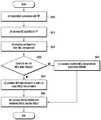
도 8은 MCS table 전환방법 1을 이용하여 MCS table 전환이 이루어지는 과정을 기지국 관점에서 각각 도시한 것이다.FIG. 8 shows the process of switching MCS tables using the MCS
도 8을 참조하면, 단계 S800에서 기지국은 단말과 접속(connection)을 형성한다.Referring to FIG. 8, in step S800, a base station forms a connection with a terminal.
단말과 연결된 기지국은 단계 S810에서 해당 단말에게 단말의 단말 능력(UE capability)를 수신한다. 상기 UE capability에는 단말이 256QAM을 지원할 수 있는지 여부에 대한 제어정보가 포함된다.The base station connected to the UE receives the UE capability of the UE in step S810. The UE capability includes control information as to whether or not the UE can support 256QAM.
만약 단말이 256QAM을 수신할 수 있는 경우에는, 단계 S820에서 기지국은 다수의 CSI-Process를 이용하여 상향 링크를 통해 전달 받는 무선 채널 정보 등을 이용하여 해당 단말이 64QAM MCS table을 사용하여야 할 지 또는 256QAM MCS table를 사용하여야 할 지를 결정한다.If the terminal can receive 256QAM, the base station determines in step S820 whether the corresponding terminal should use the 64QAM MCS table using radio channel information or the like received through the uplink using a plurality of CSI-processes, Determine if 256QAM MCS table should be used.
단계 S820에서 조건이 맞아 기지국이 단말이 256QAM MCS table을 사용하는 것으로 결정한 경우에는, 단계 S830에서 기지국은 단말에게 256QAM을 수신하도록 설정한다. 즉 기지국은 단말이 256QAM MCS table를 사용하여 스케줄되도록 설정한다. 단말이 MCS 전환방법 1의 경우 단말 별로 MCS table을 할당하게 되기 때문에 MCS table 설정에 따라 성능 차이가 커질 수 있으므로 다양한 파라미터에 대한 고려가 필요하다.In step S820, if the BS determines that the MS uses the 256QAM MCS table, the BS sets up the MS to receive 256QAM in step S830. That is, the BS sets the MS to be scheduled using the 256QAM MCS table. In the case of the
단계 S840에서 기지국은 단말에게 RRC (Radio Resource Connection) 정보와 같은 상위계층 시그널링을 이용하여 단말에게 이를 전달한다.In step S840, the BS transmits the signal to the MS using upper layer signaling such as RRC (Radio Resource Connection) information.
반대로 단계 S820에서 조건이 맞지 않아 256 QAM MCS table을 사용하지 않도록 결정한 경우에는, 단계 S850에서 기지국은 단말에게 256QAM을 수신하지 않도록 설정한다. 즉 기지국은 단말이 64QAM MCS table을 사용하여 스케줄되도록 설정한다.Conversely, if it is determined in step S820 that the 256 QAM MCS table is not used because the conditions are not met, the base station sets the mobile station to not receive 256QAM in step S850. In other words, the BS sets the MS to be scheduled using the 64QAM MCS table.
단계 S860에서 기지국은 단말에게 RRC (Radio Resource Connection) 정보와 같은 상위계층 시그널링을 이용하여 단말에게 이를 전달한다.In step S860, the BS transmits the signal to the MS using upper layer signaling such as RRC (Radio Resource Connection) information.
도 9는 MCS table 전환방법 1을 이용하여 MCS table 전환이 이루어지는 과정을 단말 관점에서 도시한 것이다.FIG. 9 shows a process of switching an MCS table using the MCS
도 9를 참조하면, 단계 S900에서 단말은 기지국과 connection을 형성한다.Referring to FIG. 9, in step S900, the terminal forms a connection with the base station.
기지국과 연결된 단말은 단계 S910에서 해당 기지국에게 단말의 UE capability를 송신한다.The terminal connected to the base station transmits the UE capability of the terminal to the corresponding base station in step S910.
이후 단말은 단계 S920과 같이 RRC와 같은 상위계층 시그널링을 받게 되고 이 신호 안에 포함된 파라미터를 해석하여, 단계 S930에서 이 파라미터가 64 QAM MCS table을 사용하도록 지시하는 것인지 혹은 256 QAM MCS table을 사용하라고 지시하는 것인지를 판단한다.Then, the terminal receives an upper layer signaling such as RRC as in step S920, analyzes the parameters included in the signal, and instructs the parameter in step S930 to use a 64 QAM MCS table or use a 256 QAM MCS table It is judged whether or not to instruct.
256 QAM으로 판명되었을 경우에는, 단계 S940과 같이, 단말은 256 QAM MCS table을 사용한다.If it is determined to be 256 QAM, the terminal uses a 256 QAM MCS table as in step S940.
반대의 경우에는, 단계 S950과 같이, 단말은 64 QAM MCS table을 사용한다. 상기 과정을 통하여 결정된 MCS table을 이용하여 단계 S960과 같이 데이터 복호화를 위한 하향 링크 제어 정보를 해석하기 시작한다.In the opposite case, the terminal uses a 64 QAM MCS table as in step S950. And analyzes the downlink control information for data decoding as in step S960 using the MCS table determined through the above process.
도 10은 MCS table 전환방법 2를 이용하여 MCS table 전환이 이루어지는 과정을 기지국 관점에서 도시한 것이다.FIG. 10 shows a process of switching an MCS table using the MCS
도 10을 참조하면, 단계 S1000에서 기지국은 단말과 connection을 형성한다.Referring to FIG. 10, in step S1000, the BS forms a connection with the MS.
단말과 연결된 기지국은 단계 S1010에서 해당 단말로부터 단말의 UE capability를 수신한다.The base station connected to the terminal receives the UE capability of the terminal from the corresponding terminal in step S1010.
단계 S1020에서 기지국은 네트워크를 통하여 해당 단말에 연결된 CSI-Process 상태 정보를 파악하고 해당 단말이 CSI-Process별 전환방법 1, 2, 3 중 하나의 방법을 이용하여 스스로 어떤 MCS table을 사용하도록 판단할 것인지를 파악한다.In step S1020, the base station determines the CSI-process status information connected to the corresponding terminal through the network and determines which MCS table is to be used by itself according to one of the switching
이 정보를 토대로 단계 S1030에서 기지국은 어떤 MCS table을 사용하여 하향 링크 데이터를 송신하여야 할지를 결정한다.Based on this information, in step S1030, the base station determines which MCS table is used to transmit downlink data.
256 QAM MCS table을 사용하는 조건일 경우에는, 단계 S1040과 같이 기지국은 해당 MCS table을 사용하도록 설정한다. 이에 따라 단계 S1040과 같이 기지국은 하향 링크 데이터를 256 QAM MCS table을 통해 송신하게 된다.In the case of using the 256 QAM MCS table, the base station sets the MCS table to be used as shown in step S1040. Accordingly, the base station transmits the downlink data through the 256 QAM MCS table as in step S1040.
마찬가지로 64 QAM MCS table을 사용하는 조건일 경우에는, 단계 S1060과 같이 기지국은 64 QAM MCS table을 사용하도록 설정한다. 이에 따라 단계 S1070과 같이 기지국은 하향 링크 데이터를 64 QAM MCS table을 통해 송신하게 된다Similarly, if the condition is to use a 64 QAM MCS table, the base station sets the 64 QAM MCS table to be used as in step S1060. Accordingly, the base station transmits the downlink data through the 64 QAM MCS table as in step S1070
도 11은 MCS table 전환방법 2를 이용하여 MCS table 전환이 이루어지는 과정을 단말 관점에서 도시한 것이다.FIG. 11 shows a process of switching an MCS table using an MCS
도 11을 참조하면, 단계 S1100에서 단말은 기지국과 connection을 형성한다.Referring to FIG. 11, in step S1100, a terminal forms a connection with a base station.
기지국과 연결된 단말은 단계 S1110에서 해당 기지국에게 단말의 UE capability를 송신한다.The terminal connected to the base station transmits the UE capability of the terminal to the corresponding base station in step S1110.
이후 단말은 단계 S1120과 같이 RRC 정보를 통해 CSI-Process 정보들을 받게 되고 이 신호 안에 포함된 파라미터를 해석하여, 다수의 TP들과 CSI-Process를 형성하게 된다.Then, the terminal receives the CSI-Process information through the RRC information as in step S1120, analyzes the parameters included in the signal, and forms a CSI-process with a plurality of TPs.
단계 S1120에서 설정된 파라미터와 CSI-Process별 전환방법 1, 2, 3 중 하나를 이용하여 기지국과 연결 된 CSI-Process 상태에 따라 단계 S1130 에서 단말은 64 QAM MCS table을 사용해야 할 지 혹은 256 QAM MCS table을 사용해야 할 지를 판단한다.Depending on the CSI-Process state connected to the base station using one of the parameters set in step S1120 and the
256 QAM으로 판명되었을 경우에는, 단계 S1140과 같이 단말은 256 QAM MCS table을 사용도록 결정한다.256 QAM, the UE determines to use the 256 QAM MCS table as in step S1140.
반대의 경우에는, 단계 S1150과 같이 단말은 64 QAM MCS table을 사용하도록 결정한다.In the opposite case, the UE determines to use the 64 QAM MCS table as in step S1150.
단말은 상기 과정을 통하여 결정된 MCS table을 이용하여 단계 S1160과 같이 데이터 복호화를 위한 하향 링크 제어 정보를 해석하기 시작한다.The MS starts to analyze downlink control information for data decoding as in step S1160 using the MCS table determined through the above process.
도 12는 MCS table 전환방법 3을 이용하여 MCS table 전환이 이루어지는 과정을 기지국 관점에서 도시한 것이다.FIG. 12 shows a process of switching an MCS table using the MCS table conversion method 3 from the viewpoint of a base station.
도 12를 참조하면, 단계 S1200에서 기지국은 단말과 connection을 형성한다.Referring to FIG. 12, in step S1200, the BS forms a connection with the MS.
단말과 연결된 기지국은 단계 S1210에서 해당 단말에게 단말의 UE capability를 수신한다.In step S1210, the base station connected to the UE receives the UE capability of the UE.
단계 S1220에서 기지국은 단말에게 64 QAM table 설정과 256 QAM table 설정이 포함된 QCL 파라미터 셋을 상위 계층 시그널링을 통해 전달한다.In step S1220, the BS transmits the QCL parameter set including the 64 QAM table setting and the 256 QAM table setting to the UE through the upper layer signaling.
이 후, 단계 S1230에서 기지국은 CSI-Process 등을 통해 얻은 무선 채널 정보와 기타 네트워크 상황 등이 256 QAM MCS table을 사용하는 조건인지 또는 CSI-Process 등을 통해 얻은 무선 채널 정보와 기타 네트워크 상황 등이 제약되어 64 QAM MCS table을 사용하는 조건인지 여부를 판단한다.After that, in step S1230, the base station determines whether the wireless channel information obtained through the CSI-Process and the other network conditions are conditions for using the 256 QAM MCS table or the wireless channel information obtained through the CSI-process and other network conditions And determines whether the condition is constrained to use 64 QAM MCS table.
단계 S1230에서 CSI-Process 등을 통해 얻은 무선 채널 정보와 기타 네트워크 상황 등이 256 QAM MCS table을 사용하는 조건일 경우에는, 단계 S1240과 같이 256 QAM MCS table을 사용하도록 설정 된 상위 QCL 파라미터에 해당하는 PQI index를 전송하여 단말이 해당 PDSCH를 복호화 하는 데에 256 QAM MCS table을 사용하도록 설정한다.If it is determined in step S1230 that the wireless channel information and other network conditions obtained through the CSI-Process or the like use the 256 QAM MCS table, then in step S1240, And transmits the PQI index to the UE to use the 256 QAM MCS table to decode the corresponding PDSCH.
반대로 단계 S1230에서 CSI-Process 등을 통해 얻은 무선 채널 정보와 기타 네트워크 상황 등이 제약되어 64 QAM MCS table을 사용하는 조건일 경우 단계 S1250과 같이 64 QAM MCS table을 사용하도록 설정 된 상위 QCL 파라미터에 해당하는 PQI index를 전송하여 단말이 해당 PDSCH를 복호화 하는 데에 64 QAM MCS table을 사용하도록 설정한다.On the contrary, if the condition of using the 64 QAM MCS table is restricted because the wireless channel information obtained through the CSI-Process and other network conditions are constrained in step S1230, it corresponds to the upper QCL parameter set to use the 64 QAM MCS table as in step S1250 And transmits the PQI index to the UE so that the UE uses the 64 QAM MCS table to decode the PDSCH.
도 13은 MCS table 전환방법 3을 이용하여 MCS table 전환이 이루어지는 과정을 단말 관점에서 도시한 것이다.FIG. 13 shows the process of switching the MCS table using the MCS table conversion method 3 from the viewpoint of the terminal.
도 13을 참조하면, 단계 S1300에서 단말은 기지국과 connection을 형성한다.Referring to FIG. 13, in step S1300, a terminal forms a connection with a base station.
기지국과 연결된 단말은 단계 S1310에서 해당 기지국에게 단말의 UE capability를 송신한다.The UE connected to the BS transmits the UE capability of the UE to the corresponding BS in step S1310.
이후 단말은 단계 S1320과 같이 상위 계층 시그널링을 통해 QCL 파라미터를 받게 된다.Then, the terminal receives QCL parameters through upper layer signaling as in step S1320.
이후, 하향 링크 제어 정보가 도착할 경우에는 단계 S1330과 같이 단말은 이 신호 안에 포함된 PQI index에 해당하는 QCL 파라미터 셋을 해석한다.When the downlink control information arrives, the UE analyzes the QCL parameter set corresponding to the PQI index included in the signal as shown in step S1330.
단계 S1340에서 단말은 상기 QCL 파라미터 셋에 포함된 필드가 MCS table을 256 QAM MCS table을 사용하도록 지정하는지 여부를 확인한다.In step S1340, the UE determines whether the field included in the QCL parameter set specifies the MCS table to use the 256 QAM MCS table.
단계 S1340에서 이 파라미터 셋에 포함된 필드가 MCS table을 256 QAM MCS table을 사용하도록 지정하는 경우에는, 단계 S1350과 같이 단말은 DCI의 MCS 해석 과정에 256 QAM MCS table을 이용하게 된다.If the field included in the parameter set specifies the MCS table to use the 256 QAM MCS table in step S1340, the UE uses the 256 QAM MCS table in the MCS analysis process of the DCI as in step S1350.
반대의 경우에는 단계 S1360과 같이 단말은 64 QAM MCS table을 이용하게 된다.In the opposite case, the UE uses the 64 QAM MCS table as in step S1360.
도 14는 Fallback 모드 유무에 따라 MCS table 전환방법 3을 이용하여 MCS table 전환이 이루어지는 과정을 기지국 관점에서 도시한 것이다.FIG. 14 shows a process of switching an MCS table using the MCS table switching method 3 according to whether there is a fallback mode from the viewpoint of a base station.
도 14를 참조하면, 단계 S1400에서 기지국은 단말과 connection을 형성한다.Referring to FIG. 14, in step S1400, a base station forms a connection with a terminal.
단말과 연결된 기지국은 단계 S1410에서 해당 단말에게 단말의 UE capability를 수신한다.The base station connected to the UE receives the UE capability of the UE from the UE in step S1410.
단계 S1420에서 기지국은 현재 PDCCH/ePDCCH 포맷 판단을 통하여 현재 전송 상태가 fallback transmission인지 일반적인 transmission인지를 판단한다.In step S1420, the BS determines whether the current transmission state is a fallback transmission or a general transmission through the PDCCH / ePDCCH format determination.
Fallback transmission 일 경우에는, 단계 S1430과 같이 기지국은 어떤 MCS table을 사용하여 하향 링크 데이터를 송신하여야 할지를 결정한다. Fallback transmission의 MCS table 전환방법 1과 같이 64 QAM을 기본적으로 사용하도록 약속된 경우에는 추가적인 동작이 필요없지만, fallback transmission의 MCS table 전환방법 2와 같이 PQI ‘00’에 설정된 상위 QCL 파라미터를 통하여 MCS table을 결정하는 경우에는 단계 S1430과 같은 결정 과정이 필요하다.In case of a fallback transmission, the BS determines which MCS table to transmit the downlink data as in step S1430. If the MCS
이 때, CSI-Process 등을 통해 얻은 무선 채널 정보와 기타 네트워크 상황 등이 256 QAM MCS table을 사용하는 조건일 경우에는 단계 S1440과 같이 기지국은 PQI ‘00’에 설정된 상위 QCL 파라미터에 단말이 해당 PDSCH를 복호화 하는데에 256 QAM MCS table을 사용하도록 설정한다.At this time, if the wireless channel information obtained through the CSI-Process and other network conditions are conditions using the 256 QAM MCS table, the BS transmits the PDSCH to the upper QCL parameter set to PQI '00' To use the 256 QAM MCS table.
반대로 CSI-Process 등을 통해 얻은 무선 채널 정보와 기타 네트워크 상황 등이 제약되어 64 QAM MCS table을 사용하는 조건일 경우 단계 1450과 같이 기지국은 PQI ‘00’에 설정 된 상위 파라미터에 단말이 해당 PDSCH를 복호화 하는데에 64 QAM MCS table을 사용하도록 설정한다.On the other hand, when the condition of using the 64 QAM MCS table is restricted because of the radio channel information obtained through the CSI-Process and other network conditions, the BS transmits the PDSCH to the upper parameter set to PQI '00' Use the 64 QAM MCS table to decode.
다시 단계 S1420으로 돌아가 현재 전송 상태가 fallback transmission이 아닌 transmission mode 10일 경우에는, 기지국은 DCI format 2D를 해석하여 PQI 정보를 인지 한다.Returning to step S1420, if the current transmission state is transmission mode 10 instead of fallback transmission, the base station interprets the DCI format 2D and recognizes the PQI information.
단계 S1460에서 기지국은 CSI-Process 등을 통해 얻은 무선 채널 정보와 기타 네트워크 상황 등이 256 QAM MCS table을 사용하는 조건인지 여부를 확인한다.In step S1460, the BS determines whether the radio channel information obtained through the CSI-Process and other network conditions are conditions for using the 256 QAM MCS table.
이 때, 단계 S1460에서 CSI-Process 등을 통해 얻은 무선 채널 정보와 기타 네트워크 상황 등이 256 QAM MCS table을 사용하는 조건일 경우에는, 단계 S1470과 같이 기지국은 현재 해당 TP의 전송에 해당하는 PQI index에 설정 된 상위 QCL 파라미터에 단말이 해당 PDSCH를 복호화 하는 데에 256 QAM MCS table을 사용하도록 설정한다.At this time, when the wireless channel information obtained through the CSI-Process or other network conditions and the like in the step S1460 is a condition using the 256 QAM MCS table, the BS transmits a PQI index The UE sets the 256 QAM MCS table to decode the corresponding PDSCH.
반대로 CSI-Process 등을 통해 얻은 무선 채널 정보와 기타 네트워크 상황 등이 제약되어 64 QAM MCS table을 사용하는 조건일 경우에는, 단계 S1480과 같이 기지국은 해당 TP의 전송에 해당하는 PQI index에 설정 된 상위 QCL 파라미터에 64 QAM MCS table을 사용하도록 설정한다.On the contrary, when the condition of using the 64 QAM MCS table is restricted due to the restriction of the radio channel information obtained through the CSI-Process and other network conditions, the base station sets the PQI index corresponding to the transmission of the corresponding TP, Set the QCL parameter to use 64 QAM MCS table.
도 15는 Fallback 모드 유무에 따라 MCS table 전환방법 3을 이용하여 MCS table 전환이 이루어지는 과정을 단말 관점에서 도시한 것이다.FIG. 15 shows a process of switching the MCS table using the MCS table switching method 3 according to the presence or absence of the fallback mode from the viewpoint of the terminal.
도 15를 참조하면, 단계 S1500에서 단말은 기지국과 connection을 형성한다.Referring to FIG. 15, in step S1500, a terminal forms a connection with a base station.
기지국과 연결된 단말은 단계 S1510에서 해당 기지국에게 단말의 UE capability를 송신한다.The terminal connected to the base station transmits the UE capability of the terminal to the corresponding base station in step S1510.
이후 단말은 단계 S1520과 같이 RRC 정보를 통해 CSI-Process 정보들을 받게 되고 이 신호 안에 포함된 파라미터를 해석하여, 다수의 TP들과 CSI-Process를 형성하게 된다.Then, the terminal receives the CSI-Process information through RRC information as in step S1520, analyzes the parameters included in the signal, and forms a CSI-process with a plurality of TPs.
단계 S1530에서 현재의 전송 모드를 파악하여 fallback transmission 일 경우에는, 단계 S1540으로 이동한다.In step S1530, the current transmission mode is grasped, and if it is a fallback transmission, the flow proceeds to step S1540.
Fallback transmission의 MCS table 전환방법 1과 같이 64 QAM을 기본적으로 사용하도록 약속된 경우에는 추가적인 동작이 필요 없이 64 QAM MCS table을 이용하여 하향 링크 데이터를 복호화하지만, fallback transmission의 MCS table 전환방법 2와 같이 PQI ‘00’에 설정 된 상위 파라미터를 통하여 MCS table을 결정하는 경우에는 단계 S1540과 같은 결정 과정이 필요하다.If MCS
단계 S1540에서 PQI 필드 ‘00’에 해당하는 상위 계층 QCL 파라미터 셋에서 MCS table을 256 QAM MCS table을 사용하도록 지정하는 경우에는, 단계 S1570과 같이 단말은 DCI의 MCS 해석 과정에 256 QAM MCS table을 이용하며, 반대의 경우에는 64 QAM MCS table을 이용한다.If it is determined in step S1540 that the MCS table is to be used for the 256 QAM MCS table in the upper layer QCL parameter set corresponding to the PQI field '00', the UE uses the 256 QAM MCS table in the MCS analysis process of the DCI as in step S1570 And in the opposite case, the 64 QAM MCS table is used.
단계 S1530에서 현재 전송 상태가 fallback transmission이 아닌 transmission mode 10일 경우에는 단계 S1550과 같이 단말은 DCI format 2D를 해석하여 PQI 정보를 인지한다.If it is determined in step S1530 that the current transmission state is transmission mode 10 instead of fallback transmission, the terminal interprets the DCI format 2D and recognizes the PQI information as shown in step S1550.
단계 S1560 에서 단말은 PQI 필드에 설정된 상위 계층 파라미터가 256 QAM MCS table을 사용하도록 설정되어 있는지 여부를 확인한다.In step S1560, the UE determines whether the upper layer parameter set in the PQI field is set to use the 256 QAM MCS table.
단계 S1560 에서 PQI 필드에 설정된 상위 계층 파라미터가 256 QAM MCS table을 사용하도록 설정된 경우에는, 단계 S1570과 같이 단말은 256 QAM MCS table을 이용하여 하향 링크 데이터를 복호화한다.If the upper layer parameter set in the PQI field is set to use the 256 QAM MCS table in step S1560, the UE decodes the downlink data using the 256 QAM MCS table as in step S1570.
반대의 경우에는 S1580과 같이 단말은 64 QAM MCS table을 이용하여 하향 링크 데이터를 복호화 한다.In the opposite case, the UE decodes the downlink data using the 64 QAM MCS table as in S1580.
도 16은 본 발명에서 제안하는 CQI 해석방법 및 MCS 정의방법을 구현하기 위한 기지국 송수신기 구조를 도시한 것이다.FIG. 16 illustrates a structure of a base station transceiver for implementing the CQI analysis method and the MCS defining method proposed in the present invention.
도 16을 참조하면, 기지국(1600)은 기지국 제어채널(PDCCH/ePDCCH) 송신기(1610), 기지국 데이터채널(PDSCH) 송신기(1620), 기지국 상향링크 채널(PUSCH/PUCCH) 수신기(1630) 및 기지국 제어기(1640)를 포함할 수 있다.16, a
기지국 제어기(1640)는 CQI 해석방법 및 MCS 정의방법의 변경이 언제 이루어지고 이를 기반으로 CQI를 어떻게 해석하고 MCS를 어떻게 결정할지를 수행한다. 즉, 기지국 제어기(1640)은 단말이 전송한 상향링크 신호를 수신기(1630)를 통하여 수신하며 여기에서 수신되는 신호로는 단말이 상향링크로 전송한 CQI index가 포함된다. 기지국 제어기(1640)은 단말이 송신한 CQI index를 적절한 CQI 해석방법에 따라 해석하여 단말의 스케줄링에 활용한다. 또한 기지국 제어기(1640)은 특정 단말의 MCS 정의방법에 따라 MCS index를 판단하고 이를 제어채널 송신기(1610)를 이용하여 단말에게 전송하며 이에 맞추어 데이터채널 송신기 (1620)을 이용하여 단말에게 PDSCH를 전송한다.The
도 17은 본 발명에서 제안하는 MCS 해석방법을 구현하기 위한 단말 송수신기 구조를 도시한 것이다.17 illustrates a structure of a UE transceiver for implementing the MCS analysis method proposed by the present invention.
도 17을 참조하며, 단말(1700)는 단말 상향링크 채널(PUCCH/PUSCH) 송신기(1710), 단말 제어채널(PDCCH/ePDCCH) 수신기(1720), 단말 데이터채널(PDSCH) 수신기(1730) 및 단말 제어기(1740)를 포함할 수 있다.17, a
단말 제어기(1740)는 CQI 정의방법 및 MCS 해석방법의 변경이 언제 이루어지고 이를 기반으로 CQI index를 어떻게 정의하고 MCS index를 어떻게 해석할지를 수행한다. 즉, 제어기(1740)는 기지국이 전송한 MCS index를 제어채널 수신기(1720)를 통하여 통보받고 이를 이용하여 데이터채널 수신기(1730)을 통하여 PDSCH를 수신한다. 또한 제어기(1740)는 CQI의 정의방법에 따라 적절한 CQI index를 결정하여 상향링크 채널 송신기(1740)를 통하여 기지국에 전달한다.The
컴퓨터 프로그램 명령이 일반 컴퓨터, 특수 컴퓨터, 또는 다른 프로그래밍가능한 데이터 프로세싱 장비의 프로세서에 장착될 수 있으므로, 컴퓨터 또는 다른 프로그래밍가능한 데이터 프로세싱 장비의 프로세서를 통해 수행된 명령은 흐름도의 블록(들)에 설명된 기능을 수행하는 수단을 생성한다. 컴퓨터 프로그램 명령은 특정 구조로 기능을 구현하도록 컴퓨터 또는 다른 프로그래밍가능한 데이터 프로세싱 장비를 배향할 수 있는 컴퓨터 또는 컴퓨터 판독가능한 메모리에 저장될 수 있으므로, 컴퓨터 또는 컴퓨터 판독가능한 메모리에 저장된 명령은 흐름도의 블록(들)에 설명된 기능을 실행하는 명령 수단을 수반하는 제조 물품(manufacturing article)을 생산할 수 있다. 컴퓨터 프로그램 명령이 컴퓨터 또는 다른 프로그래밍가능한 데이터 프로세싱 장비에 장착될 수 있으므로, 일련의 동작 단계들이 컴퓨터에 의해 실행된 프로세스를 생성하도록 컴퓨터 또는 다른 프로그래밍가능한 데이터 프로세싱 장비에서 수행되어 컴퓨터 또는 다른 프로그래밍가능한 데이터 프로세싱 장비에 의해 수행된 명령은 흐름도의 블록(들)에 설명된 기능을 실행하는 단계를 제공할 수 있다.Because the computer program instructions may be embedded in a processor of a general computer, special purpose computer, or other programmable data processing apparatus, instructions performed via a processor of a computer or other programmable data processing apparatus may be stored in a computer- Thereby creating means for performing the function. Computer program instructions may be stored in a computer or computer readable memory capable of orienting a computer or other programmable data processing apparatus to implement a function in a particular structure so that instructions stored in a computer or computer readable memory may be stored in a block To produce a manufacturing article that is accompanied by an instruction means to perform the functions described in the above. Because the computer program instructions may be embedded in a computer or other programmable data processing apparatus, a series of operating steps may be performed on the computer or other programmable data processing apparatus to create a process executed by the computer to perform a computer or other programmable data processing The instructions performed by the equipment may provide a step of implementing the functions described in the block (s) of the flowchart.
나아가, 각 블록은 특정 논리 기능(들)을 실행하는 적어도 하나의 실행가능한 명령을 포함하는 모듈, 세그먼트, 또는 코드의 일부를 나타낼 수 있다. 여러 실행 예시들은 블록으로 설명된 기능을 순서를 벗어나게 생성할 수 있는 것으로 이해된다. 예를 들어, 2개의 연속적으로 도시된 블록은 동시에 수행되거나, 블록은 대응하는 기능에 따라 역순으로 수행될 수 있다.Furthermore, each block may represent a module, segment, or portion of code that includes at least one executable instruction that executes a particular logical function (s). It is to be understood that the various exemplary implementations are capable of generating functions described in blocks out of order. For example, two consecutively shown blocks may be performed at the same time, or the blocks may be performed in reverse order according to the corresponding function.
본 명세서에 사용된 바와 같이, "유닛"이라는 용어는 전계 프로그래밍가능한 게이트 어레이(FPGA) 또는 애플리케이션 특정 집적 회로(ASIC)와 같은 소프트웨어 또는 하드웨어 구조 요소를 말하고, 이 "유닛"은 일부 역할을 수행한다. 그러나, 이 "유닛"은 소프트웨어 또는 하드웨어로 제한되지 않는다. 이 "유닛"은 어드레스가능한 저장 매체에 저장되고 적어도 하나의 프로세서를 플레이하도록 구성될 수 있다. 따라서, 예를 들어, 이 "유닛"은 소프트웨어 구조적인 요소, 객체 지향 소프트웨어 구조적인 요소, 클래스 구조적인 요소, 태스크 구조적인 요소, 프로세스, 기능, 속성, 절차, 서브루틴, 프로그램 코드의 세그먼트, 드라이버, 펌웨어, 마이크로코드, 회로, 데이터, 데이터베이스, 데이터 구조, 테이블, 어레이, 및 변수를 포함한다. 구조적인 요소 및 "유닛"에 제공된 기능은 더 적은 수의 구조적인 요소 및 "유닛"로 수행될 수 있고, 또는 추가적인 구조적인 요소 및 "유닛"에 의해 분할될 수 있다. 더욱이, 구조적인 요소 및 "유닛"은 보안 멀티미디어 카드에서 디바이스 또는 적어도 하나의 CPU를 플레이하도록 구현될 수 있다.As used herein, the term "unit" refers to a software or hardware structure element, such as an electric field programmable gate array (FPGA) or application specific integrated circuit (ASIC), which performs some role . However, this "unit" is not limited to software or hardware. This "unit" may be stored in an addressable storage medium and configured to play at least one processor. Thus, for example, this "unit" may be a software structural element, an object oriented software structural element, a class structural element, a task structural element, a process, a function, an attribute, a procedure, a subroutine, , Firmware, microcode, circuitry, data, databases, data structures, tables, arrays, and variables. The structural elements and functions provided in a "unit" may be performed with fewer structural elements and "units ", or may be divided by additional structural elements and" units ". Moreover, the structural elements and "unit" may be implemented to play a device or at least one CPU in a secure multimedia card.
본 발명이 특정 예시적인 실시예를 참조하여 도시되고 설명되었으나, 이 기술 분야에 통상의 지식을 가진 자라면 첨부된 청구범위 및 그 균등 범위를 벗어남이 없이 이들 형태 및 상세에 여러 변형이 이루어질 수 있다는 것을 이해할 수 있을 것이다.While the present invention has been shown and described with reference to specific exemplary embodiments thereof, it is evident that many alternatives, modifications, and variations will occur to those skilled in the art without departing from the scope of the appended claims and their equivalents You will understand.
Claims (25)
Translated fromKoreanCSI-Prcocess(Channel Status Information Process)를 통해 획득된 정보를 기초로 256 QAM을 지원하는 제1 MCS(Modulation Coding Scheme) 테이블 및 256 QAM 을 지원하지 않는 제2 MCS 테이블 중 하나를 선택하는 단계; 및
상기 선택된 MCS 테이블을 이용하여 단말이 스케줄되도록 설정하는 단계를 포함하는 것을 특징으로 하는 것을 특징으로 하는 데이터 전송 방법.A data transmission method for a base station in a cooperative communication system,
Selecting one of a first MCS (Modulation Coding Scheme) table that supports 256 QAM and a second MCS table that does not support 256 QAM based on the information obtained through the CSI-Prcocess (Channel Status Information Process); And
And setting the terminal to be scheduled using the selected MCS table.
CSI-Prcocess(Channel Status Information Process)를 통해 획득된 정보는 무선 채널 정보 및 CQI 테이블 정보 중 적어도 하나를 포함하는 것을 특징으로 하는 데이터 전송 방법.The method according to claim 1,
Wherein the information obtained through the CSI-Prcocess (Channel Status Information Process) includes at least one of radio channel information and CQI table information.
상위 계층 시그널링을 이용하여 상기 선택된 MCS 테이블을 알리는 정보를 상기 단말로 전송하는 단계를 더 포함하는 데이터 전송 방법.The method according to claim 1,
And transmitting information informing the selected MCS table to the terminal using upper layer signaling.
상기 선택된 MCS 테이블을 알리는 정보는 RRC (Radio Resource Connection) 정보에 포함되어 전송되는 것을 특징으로 하는 데이터 전송 방법.The method of claim 3,
And information indicating the selected MCS table is included in RRC (Radio Resource Connection) information.
상기 하나를 선택하는 단계는,
다수의 기지국 각각과 상기 단말 사이에 사용되는 CQI(Channel Quality Indicator) 테이블 정보를 기초로 상기 제1 MCS 테이블 및 제2 MCS 테이블 중 하나를 선택하는 단계를 포함하는 것을 특징으로 하는 데이터 전송 방법.The method according to claim 1,
Wherein said selecting one comprises:
And selecting one of the first MCS table and the second MCS table based on CQI (Channel Quality Indicator) table information used between each of the plurality of base stations and the terminal.
상기 다수의 기지국 중 어느 하나와 상기 단말 사이에 64QAM 기반 CQI 테이블을 사용하는 경우에는, 상기 제2 MCS 테이블을 선택하는 것을 특징으로 하는 데이터 전송 방법.6. The method of claim 5,
Wherein when the 64QAM-based CQI table is used between any one of the plurality of base stations and the terminal, the second MCS table is selected.
상기 다수의 기지국 중 절반 이상과 상기 단말 사이에 256QAM 기반 CQI 테이블을 사용하는 경우에는, 상기 제1 MCS 테이블을 선택하는 것을 특징으로 하는 데이터 전송 방법.6. The method of claim 5,
If the 256QAM CQI table is used between more than half of the plurality of base stations and the terminal, the first MCS table is selected.
상기 다수의 기지국 중 어느 하나와 상기 단말 사이에 256QAM 기반 CQI 테이블을 사용하는 경우에는, 상기 제1 MCS 테이블을 선택하는 것을 특징으로 하는 데이터 전송 방법.6. The method of claim 5,
Wherein the first MCS table is selected when a 256QAM CQI table is used between any one of the plurality of base stations and the terminal.
상기 선택된 MCS 테이블을 사용하도록 설정된 상위 QCL(Quasi-Colocation) 파라미터에 해당하는 PQI(PDSCH RE Mapping and Quasi-Co-Location Indicator) 인덱스(index)를 상기 단말에 전송하는 단계를 더 포함하는 것을 특징으로 하는 데이터 전송 방법.The method according to claim 1,
(PQI) index corresponding to an upper QCL (Quasi-Colocation) parameter set to use the selected MCS table to the UE. / RTI >
현재 전송 상태가 폴백 전송(fallback transmission)인지 여부를 확인하는 단계를 더 포함하는 것을 특징으로 하는 데이터 전송 방법.The method according to claim 1,
Further comprising the step of: determining whether the current transmission status is a fallback transmission.
현재 전송 상태가 상기 폴백 전송인 경우에는, 상기 제2 MCS 테이블을 선택하는 것을 특징으로 하는 데이터 전송 방법.11. The method of claim 10,
And if the current transmission state is the fallback transmission, selecting the second MCS table.
현재 전송 상태가 상기 폴백 전송인 경우에는, PQI(PDSCH RE Mapping and Quasi-Co-Location Indicator) 인덱스(index) '00'에 설정된 상위 QCL(Quasi-Colocation) 파라미터에 상기 단말이 상기 선택된 MCS 테이블을 사용하도록 설정하는 단계를 더 포함하는 것을 특징으로 하는 데이터 전송 방법.11. The method of claim 10,
If the current transmission state is the fallback transmission, the UE transmits the selected MCS table to an upper QCL (Quasi-Colocation) parameter set in the PDSCH RE Mapping and Quasi-Co-Location Indicator (PQI) index '00' The method comprising the steps of:
현재 전송 상태가 상기 폴백 전송이 아닌 경우에는, 현재 전송 상태가 전송 모드 10(transmission mode 10)인지 확인하는 단계; 및
현재 전송 산태가 transmission mode 10인 경우에는, 현재 상기 기지국의 전송에 해당하는 PQIPQI(PDSCH RE Mapping and Quasi-Co-Location Indicator) 인덱스(index)에 설정된 상위 QCL(Quasi-Colocation) 파라미터에 상기 단말이 상기 선택된 MCS 테이블을 사용하도록 설정하는 단계를 더 포함하는 것을 특징으로 하는 데이터 전송 방법.11. The method of claim 10,
If the current transmission state is not the fallback transmission, checking whether the current transmission state is transmission mode 10; And
When the current transmission mode is the transmission mode 10, the UE determines whether the current transmission mode is the upper QCL (Quasi-Colocation) parameter set in the PQIP QI (REQ Mapping and Quasi-Co-Location Indicator) And setting the selected MCS table to use the selected MCS table.
DCI format 2D를 이용하여 상기 PQI index를 인지하는 단계를 더 포함하는 것을 특징으로 하는 데이터 전송 방법.14. The method of claim 13,
Further comprising the step of recognizing the PQI index using a DCI format 2D.
CSI-Prcocess(Channel Status Information Process)를 통해 획득된 정보를 기초로 256 QAM을 지원하는 제1 MCS(Modulation Coding Scheme) 테이블 및 256 QAM 을 지원하지 않는 제2 MCS 테이블 중 하나를 선택하고, 상기 선택된 MCS 테이블을 이용하여 단말이 스케줄되도록 설정하는 제어부를 포함하는 것을 특징으로 하는 기지국.A transmitter for transmitting a channel status information reference signal (CSI-RS) to the UE; And
Selects one of a first MCS (Modulation Coding Scheme) table that supports 256 QAM and a second MCS table that does not support 256 QAM based on the information obtained through the CSI-Prcocess (Channel Status Information Process) And a controller configured to set a terminal to be scheduled using an MCS table.
256 QAM을 지원하는 제1 MCS(Modulation Coding Scheme) 테이블 및 256 QAM 을 지원하지 않는 제2 MCS 테이블 중 하나를 지시하는 정보를 수신하는 단계; 및
상기 수신된 정보가 지시하는 MCS 테이블을 사용하는 단계를 포함하는 것을 특징으로 하는 데이터 수신 방법.A data reception method for a terminal in a cooperative communication system,
Receiving information indicating one of a first MCS (Modulation Coding Scheme) table that supports 256 QAM and a second MCS table that does not support 256 QAM; And
And using the MCS table indicated by the received information.
상기 정보는 상위 계층 시그널링을 통해 전송되는 것을 특징으로 하는 데이터 수신 방법.17. The method of claim 16,
Wherein the information is transmitted via higher layer signaling.
상기 정보는 RRC (Radio Resource Connection) 정보에 포함되어 전송되는 것을 특징으로 하는 데이터 수신 방법.18. The method of claim 17,
Wherein the information is included in RRC (Radio Resource Connection) information.
상기 정보는 QCL(Quasi-Colocation) 파라미터 셋에 포함되어 전송되는 것을 특징으로 하는 데이터 수신 방법.17. The method of claim 16,
Wherein the information is transmitted in a QCL (Quasi-Colocation) parameter set.
다수의 기지국 각각과 상기 단말 사이에 사용되는 CQI(Channel Quality Indicator) 테이블 정보를 기초로 256 QAM을 지원하는 제1 MCS(Modulation Coding Scheme) 테이블 및 256 QAM 을 지원하지 않는 제2 MCS 테이블 중 하나를 선택하는 단계; 및
상기 선택된 MCS 테이블을 사용하는 단계를 포함하는 것을 특징으로 하는 데이터 수신 방법.A data reception method for a terminal in a cooperative communication system,
A first MCS (Modulation Coding Scheme) table that supports 256 QAM and a second MCS table that does not support 256 QAM based on CQI (Channel Quality Indicator) table information used between each of the plurality of base stations and the terminal Selecting; And
And using the selected MCS table.
상기 다수의 기지국 중 어느 하나와 상기 단말 사이에 64QAM 기반 CQI 테이블을 사용하는 경우에는, 상기 제2 MCS 테이블을 선택하는 것을 특징으로 하는 데이터 수신 방법.21. The method of claim 20,
Wherein when the 64QAM-based CQI table is used between any one of the plurality of base stations and the terminal, the second MCS table is selected.
상기 다수의 기지국 중 절반 이상과 상기 단말 사이에 256QAM 기반 CQI 테이블을 사용하는 경우에는, 상기 제1 MCS 테이블을 선택하는 것을 특징으로 하는 데이터 수신 방법.21. The method of claim 20,
Wherein the first MCS table is selected when a 256QAM CQI table is used between more than half of the plurality of base stations and the terminal.
상기 다수의 기지국 중 어느 하나와 상기 단말 사이에 256QAM 기반 CQI 테이블을 사용하는 경우에는, 상기 제1 MCS 테이블을 선택하는 것을 특징으로 하는 데이터 수신 방법.21. The method of claim 20,
Wherein when the 256QAM-based CQI table is used between any one of the plurality of base stations and the terminal, the first MCS table is selected.
상기 수신된 정보가 지시하는 MCS 테이블을 사용하는 제어부를 포함하는 것을 특징으로 하는 단말.A receiver for receiving information indicating one of a first MCS (Modulation Coding Scheme) table supporting 256 QAM and a second MCS table not supporting 256 QAM; And
And a controller using the MCS table indicated by the received information.
상기 다수의 기지국 각각과 단말 사이에 사용되는 CQI(Channel Quality Indicator) 테이블 정보를 기초로 256 QAM을 지원하는 제1 MCS(Modulation Coding Scheme) 테이블 및 256 QAM을 지원하지 않는 제2 MCS 테이블 중 하나를 선택하고, 상기 선택된 MCS 테이블을 사용하는 제어부를 포함하는 것을 특징으로 하는 단말.A receiver for receiving a channel status information reference signal (CSI-RS) from a plurality of base stations; And
A first MCS (Modulation Coding Scheme) table supporting 256 QAM and a second MCS table not supporting 256 QAM based on CQI (Channel Quality Indicator) table information used between each of the plurality of base stations and the UE And using the selected MCS table.
Priority Applications (1)
| Application Number | Priority Date | Filing Date | Title |
|---|---|---|---|
| KR1020130150218AKR20150065231A (en) | 2013-12-04 | 2013-12-04 | Data transmission method and data reception method, terminal and base station |
Applications Claiming Priority (1)
| Application Number | Priority Date | Filing Date | Title |
|---|---|---|---|
| KR1020130150218AKR20150065231A (en) | 2013-12-04 | 2013-12-04 | Data transmission method and data reception method, terminal and base station |
Publications (1)
| Publication Number | Publication Date |
|---|---|
| KR20150065231Atrue KR20150065231A (en) | 2015-06-15 |
Family
ID=53504187
Family Applications (1)
| Application Number | Title | Priority Date | Filing Date |
|---|---|---|---|
| KR1020130150218AWithdrawnKR20150065231A (en) | 2013-12-04 | 2013-12-04 | Data transmission method and data reception method, terminal and base station |
Country Status (1)
| Country | Link |
|---|---|
| KR (1) | KR20150065231A (en) |
Cited By (3)
| Publication number | Priority date | Publication date | Assignee | Title |
|---|---|---|---|---|
| US9419696B2 (en) | 2011-12-19 | 2016-08-16 | Comcast Cable Communications, Llc | Beam information exchange between base stations |
| US10085165B2 (en) | 2011-09-23 | 2018-09-25 | Comcast Cable Communications, Llc | Multi-cell signals in OFDM wireless networks |
| US12445912B2 (en) | 2022-05-11 | 2025-10-14 | Comcast Cable Communications, Llc | Beamforming in wireless communications |
- 2013
- 2013-12-04KRKR1020130150218Apatent/KR20150065231A/ennot_activeWithdrawn
Cited By (36)
| Publication number | Priority date | Publication date | Assignee | Title |
|---|---|---|---|---|
| US10085165B2 (en) | 2011-09-23 | 2018-09-25 | Comcast Cable Communications, Llc | Multi-cell signals in OFDM wireless networks |
| US12250584B2 (en) | 2011-09-23 | 2025-03-11 | Comcast Cable Communications, Llc | Multi-cell signals in OFDM wireless networks |
| US11871262B2 (en) | 2011-09-23 | 2024-01-09 | Comcast Cable Communications, Llc | Multi-cell signals in OFDM wireless networks |
| US11611897B2 (en) | 2011-09-23 | 2023-03-21 | Comcast Cable Communications, Llc | Multi-cell signals in OFDM wireless networks |
| US11432180B2 (en) | 2011-09-23 | 2022-08-30 | Comcast Cable Communications, Llc | Multi-cell signals in OFDM wireless networks |
| US10917807B2 (en) | 2011-09-23 | 2021-02-09 | Comcast Cable Communications, Llc | Multi-cell signals in OFDM wireless networks |
| US10667164B2 (en) | 2011-09-23 | 2020-05-26 | Comcast Cable Communications, Llc | Multi-cell signals in OFDM wireless networks |
| US10306506B2 (en) | 2011-09-23 | 2019-05-28 | Comcast Cable Communications, Llc | Multi-cell signals in OFDM wireless networks |
| US10715228B2 (en) | 2011-12-19 | 2020-07-14 | Comcast Cable Communications, Llc | Beamforming signaling in a wireless network |
| US10966124B2 (en) | 2011-12-19 | 2021-03-30 | Comcast Cable Communications, Llc | Beamforming codeword exchange between base stations |
| US10181883B2 (en) | 2011-12-19 | 2019-01-15 | Comcast Cable Communications, Llc | Beamforming signaling in a wireless network |
| US10193605B2 (en) | 2011-12-19 | 2019-01-29 | Comcast Cable Communications, Llc | Beamforming codeword exchange between base stations |
| US10236956B2 (en) | 2011-12-19 | 2019-03-19 | Comcast Cable Communications, Llc | Beamforming handover messaging in a wireless network |
| US9917625B2 (en) | 2011-12-19 | 2018-03-13 | Comcast Cable Communications, Llc | Handover signaling for beamforming communications |
| US10530438B2 (en) | 2011-12-19 | 2020-01-07 | Comcast Cable Communications, Llc | Beamforming handover messaging in a wireless network |
| US10530439B2 (en) | 2011-12-19 | 2020-01-07 | Comcast Cable Communications, Llc | Beamforming handover messaging in a wireless network |
| US10601476B2 (en) | 2011-12-19 | 2020-03-24 | Comcast Cable Communications, Llc | Beam information exchange between base stations |
| US9826442B2 (en) | 2011-12-19 | 2017-11-21 | Comcast Cable Communications, Llc | Beam information exchange between base stations |
| US9419696B2 (en) | 2011-12-19 | 2016-08-16 | Comcast Cable Communications, Llc | Beam information exchange between base stations |
| US10804987B2 (en) | 2011-12-19 | 2020-10-13 | Comcast Cable Communications, Llc | Beamforming handover messaging in a wireless network |
| US9788244B2 (en) | 2011-12-19 | 2017-10-10 | Comcast Cable Communications, Llc | Beamforming signaling in a wireless network |
| US9917624B2 (en) | 2011-12-19 | 2018-03-13 | Comcast Cable Communications, Llc | Beamforming handover messaging in a wireless network |
| US10966125B2 (en) | 2011-12-19 | 2021-03-30 | Comcast Cable Communications, Llc | Beam information exchange between base stations |
| US11082896B2 (en) | 2011-12-19 | 2021-08-03 | Comcast Cable Communications, Llc | Beamforming signaling in a wireless network |
| US11375414B2 (en) | 2011-12-19 | 2022-06-28 | Comcast Cable Communications, Llc | Beamforming in wireless communications |
| US9680544B2 (en) | 2011-12-19 | 2017-06-13 | Comcast Cable Communications, Llc | Beamforming codeword exchange between base stations |
| US11510113B2 (en) | 2011-12-19 | 2022-11-22 | Comcast Cable Communications, Llc | Beamforming handover messaging in a wireless network |
| US11516713B2 (en) | 2011-12-19 | 2022-11-29 | Comcast Cable Communications, Llc | Beamforming handover messaging in a wireless network |
| US9455775B2 (en) | 2011-12-19 | 2016-09-27 | Comcast Cable Communications, Llc | Handover signaling for beamforming communications |
| US11647430B2 (en) | 2011-12-19 | 2023-05-09 | Comcast Cable Communications, Llc | Signaling in a wireless network |
| US9450656B2 (en) | 2011-12-19 | 2016-09-20 | Comcast Cable Communications, Llc | Beamforming handover messaging in a wireless network |
| US11950145B2 (en) | 2011-12-19 | 2024-04-02 | Comcast Cable Communications, Llc | Beamforming in wireless communications |
| US12185168B2 (en) | 2011-12-19 | 2024-12-31 | Comcast Cable Communications, Llc | Beamforming handover messaging in a wireless network |
| US9444535B2 (en) | 2011-12-19 | 2016-09-13 | Comcast Cable Communications, Llc | Beamforming signaling in a wireless network |
| US12335798B2 (en) | 2011-12-19 | 2025-06-17 | Comcast Cable Communications, Llc | Beamforming in wireless communications |
| US12445912B2 (en) | 2022-05-11 | 2025-10-14 | Comcast Cable Communications, Llc | Beamforming in wireless communications |
Similar Documents
| Publication | Publication Date | Title |
|---|---|---|
| JP6901598B2 (en) | Systems and methods for adaptive modulation | |
| US11108529B2 (en) | Method and apparatus for detecting signals of a downlink control channel in a wireless communication system | |
| CN109565403B (en) | Transmission of Physical Downlink Control Channels in Communication Systems | |
| JP6103129B2 (en) | Method for configuring channel quality indication, method and apparatus for configuring modulation and coding scheme | |
| CN106685587B (en) | Method and device for determining modulation order and transmission block size in downlink data channel | |
| US20200128529A1 (en) | Data transmission method and apparatus | |
| KR102347644B1 (en) | Downlink transmission method and user terminal equipment | |
| CN110519017B (en) | Method for determining transport block size and apparatus therefor | |
| US9344240B2 (en) | 256QAM signal transmission/reception method and apparatus for use in mobile communication system | |
| KR101896164B1 (en) | Systems and methods for modulation and coding scheme selection and configuration | |
| CN108235414B (en) | Techniques for managing power consumption of a mobile device | |
| KR101814341B1 (en) | Method for Determining the Transport Block Size and Apparatuses thereof | |
| KR101634747B1 (en) | Channel state information reference signal (csi-rs) configuration and csi reporting restrictions | |
| RU2637779C2 (en) | Method and device for transmitting/receiving information on channel state | |
| ES2827218T3 (en) | Identification of modulation and coding schemes and channel quality indicators | |
| CN111224763B (en) | Downlink transmission method and user terminal equipment | |
| EP3264655A1 (en) | Methods and devices for control channel decoding | |
| KR20150034808A (en) | Method and device for transmitting mcs indication information | |
| KR20140056899A (en) | Method and apparatus for interference aware detection in wireless communication system | |
| US11765744B2 (en) | Method for cell cyclic downlink transmission in wireless communication system and apparatus therefor | |
| WO2014178486A1 (en) | Method for removing interference in wireless communication system and device for same | |
| JP7197280B2 (en) | TERMINAL DEVICE, BASE STATION DEVICE, AND COMMUNICATION METHOD | |
| CN110574315A (en) | Enhancement of modulation order determination | |
| RU2739589C2 (en) | Base station device, a terminal device and a communication method | |
| KR20150065231A (en) | Data transmission method and data reception method, terminal and base station |
Legal Events
| Date | Code | Title | Description |
|---|---|---|---|
| PA0109 | Patent application | Patent event code:PA01091R01D Comment text:Patent Application Patent event date:20131204 | |
| PG1501 | Laying open of application | ||
| PC1203 | Withdrawal of no request for examination | ||
| WITN | Application deemed withdrawn, e.g. because no request for examination was filed or no examination fee was paid |