KR20150047780A - Electronic device with electrical connector - Google Patents
Electronic device with electrical connectorDownload PDFInfo
- Publication number
- KR20150047780A KR20150047780AKR1020130127650AKR20130127650AKR20150047780AKR 20150047780 AKR20150047780 AKR 20150047780AKR 1020130127650 AKR1020130127650 AKR 1020130127650AKR 20130127650 AKR20130127650 AKR 20130127650AKR 20150047780 AKR20150047780 AKR 20150047780A
- Authority
- KR
- South Korea
- Prior art keywords
- connector
- electronic device
- magnetic body
- connection
- housing
- Prior art date
- Legal status (The legal status is an assumption and is not a legal conclusion. Google has not performed a legal analysis and makes no representation as to the accuracy of the status listed.)
- Withdrawn
Links
Images


Classifications
- H—ELECTRICITY
- H01—ELECTRIC ELEMENTS
- H01R—ELECTRICALLY-CONDUCTIVE CONNECTIONS; STRUCTURAL ASSOCIATIONS OF A PLURALITY OF MUTUALLY-INSULATED ELECTRICAL CONNECTING ELEMENTS; COUPLING DEVICES; CURRENT COLLECTORS
- H01R13/00—Details of coupling devices of the kinds covered by groups H01R12/70 or H01R24/00 - H01R33/00
- H01R13/62—Means for facilitating engagement or disengagement of coupling parts or for holding them in engagement
- H01R13/6205—Two-part coupling devices held in engagement by a magnet
- H—ELECTRICITY
- H01—ELECTRIC ELEMENTS
- H01R—ELECTRICALLY-CONDUCTIVE CONNECTIONS; STRUCTURAL ASSOCIATIONS OF A PLURALITY OF MUTUALLY-INSULATED ELECTRICAL CONNECTING ELEMENTS; COUPLING DEVICES; CURRENT COLLECTORS
- H01R11/00—Individual connecting elements providing two or more spaced connecting locations for conductive members which are, or may be, thereby interconnected, e.g. end pieces for wires or cables supported by the wire or cable and having means for facilitating electrical connection to some other wire, terminal, or conductive member, blocks of binding posts
- H01R11/11—End pieces or tapping pieces for wires, supported by the wire and for facilitating electrical connection to some other wire, terminal or conductive member
- H01R11/30—End pieces held in contact by a magnet
- H—ELECTRICITY
- H01—ELECTRIC ELEMENTS
- H01R—ELECTRICALLY-CONDUCTIVE CONNECTIONS; STRUCTURAL ASSOCIATIONS OF A PLURALITY OF MUTUALLY-INSULATED ELECTRICAL CONNECTING ELEMENTS; COUPLING DEVICES; CURRENT COLLECTORS
- H01R13/00—Details of coupling devices of the kinds covered by groups H01R12/70 or H01R24/00 - H01R33/00
- H01R13/44—Means for preventing access to live contacts
- H01R13/447—Shutter or cover plate
- H01R13/453—Shutter or cover plate opened by engagement of counterpart
- H01R13/4538—Covers sliding or withdrawing in the direction of engagement
- H—ELECTRICITY
- H01—ELECTRIC ELEMENTS
- H01R—ELECTRICALLY-CONDUCTIVE CONNECTIONS; STRUCTURAL ASSOCIATIONS OF A PLURALITY OF MUTUALLY-INSULATED ELECTRICAL CONNECTING ELEMENTS; COUPLING DEVICES; CURRENT COLLECTORS
- H01R13/00—Details of coupling devices of the kinds covered by groups H01R12/70 or H01R24/00 - H01R33/00
- H01R13/64—Means for preventing incorrect coupling
- H—ELECTRICITY
- H01—ELECTRIC ELEMENTS
- H01R—ELECTRICALLY-CONDUCTIVE CONNECTIONS; STRUCTURAL ASSOCIATIONS OF A PLURALITY OF MUTUALLY-INSULATED ELECTRICAL CONNECTING ELEMENTS; COUPLING DEVICES; CURRENT COLLECTORS
- H01R2201/00—Connectors or connections adapted for particular applications
- H01R2201/06—Connectors or connections adapted for particular applications for computer periphery
Landscapes
- Details Of Connecting Devices For Male And Female Coupling (AREA)
Abstract
Translated fromKoreanDescription
Translated fromKorean본 개시는 전자 장치에 관한 것으로서, 예컨대, 전자 장치들 간의 접속을 제공하는 접속 장치에 관한 것이다.This disclosure relates to electronic devices, for example, to connection devices that provide connections between electronic devices.
통상적으로 전자 장치라 함은, 가전제품으로부터, 전자 수첩, 휴대용 멀티미디어 재생기, 이동통신 단말기, 태블릿 PC, 영상/음향 장치, 데스크톱 / 랩톱 컴퓨터, 차량용 내비게이션 등, 탑재된 프로그램에 따라 특정 기능을 수행하는 장치를 의미한다. 예를 들면, 이러한 전자 장치들은 저장된 정보를 음향이나 영상으로 출력할 수 있다. 전자 장치의 집적도가 높아지고, 초고속, 대용량 무선통신이 보편화되면서, 최근에는, 이동통신 단말기 하나에 다양한 기능이 탑재되고 있다. 예를 들면, 통신 기능뿐만 아니라, 게임과 같은 엔터테인먼트 기능, 음악/동영상 재생과 같은 멀티미디어 기능, 모바일 뱅킹 등을 위한 통신 및 보안 기능, 일정 관리나 전자 지갑 등의 기능이 하나의 전자 장치에 집약되고 있는 것이다. 이동통신 단말기 등의 전자 장치를 이용한 멀티미디어 서비스나 엔터테인먼트 기능이 강화됨에 따라, 사용자들은 휴대가 간편하면서도 충분한 크기의 디스플레이 장치를 제공하는 전자 장치를 선호하는 추세이다.Typically, an electronic device refers to a device that performs a specific function according to a program loaded from a home appliance to an electronic notebook, a portable multimedia player, a mobile communication terminal, a tablet PC, a video / audio device, a desktop / laptop computer, Device. For example, such electronic devices may output stored information as sound or video. As the degree of integration of electronic devices increases, ultra-high-speed and large-capacity wireless communications become popular, and various functions are currently being installed in one mobile communication terminal. For example, not only communication functions but also entertainment functions such as games, multimedia functions such as music / video playback, communication and security functions for mobile banking, and functions such as schedule management and electronic wallet are integrated into one electronic device It is. As a multimedia service or an entertainment function using an electronic device such as a mobile communication terminal is strengthened, users tend to prefer an electronic device that provides a display device that is portable and has a sufficient size.
대용량의 파일, 예를 들면, 고화질 동영상 파일을 다른 전자 장치로 저장하거나, 전자 장치의 소프트웨어 업그레이드, 충전 등을 위해, 전자 장치는 다른 기기, 예컨대, 개인용 컴퓨터나 충전기와 같은 외부 기기와 접속하게 된다. 최근에는 블루투스나 근접 무선통신(near field communication; NFC)과 같은 무선통신 방식으로 전자 장치들 사이에 접속을 제공할 수 있으며, 무선 전력 송신 기술이 상용화되기도 했다. 하지만, 아직까지 유선 접속 방식이 접속 안정성이나 전력 송신 효율에서는 무선 접속 방식보다 우수한 것이 현실이다.The electronic device is connected to an external device such as a personal computer or a charger, for storing a large-capacity file, for example, a high-definition movie file in another electronic device, or for upgrading or charging the electronic device . In recent years, a wireless communication method such as Bluetooth or near field communication (NFC) can provide a connection between electronic devices, and wireless power transmission technology has also been commercialized. However, it is a reality that the wired connection method is superior to the wireless connection method in terms of the connection stability and the power transmission efficiency.
충전기나 다른 전자 장치와의 접속을 위해, 전자 장치는 접속 장치를 구비할 수 있다. 접속 장치들은 복수의 접속 핀이나 접속 핀에 상응하는 접속 단자들을 구비할 수 있다. 이러한 접속 장치들의 접속 구조는, 플러그 형태의 삽입식 접속 구조가 일반적이다. 삽입식 접속 구조는 소켓과, 소켓에 삽입되는 플러그의 조합으로 이루어지며, 안정된 결속 상태를 유지하기 위해서는 소켓에 삽입되는 플러그의 길이를 충분히 확보할 필요가 있다.For connection with a charger or other electronic device, the electronic device may have a connection device. The connection devices may have connection terminals corresponding to a plurality of connection pins or connection pins. Such a connection structure of the connection devices is generally a plug-type insertion type connection structure. The insertion type connection structure is formed by a combination of a socket and a plug inserted into the socket. In order to maintain a stable binding state, it is necessary to secure a sufficient length of the plug inserted into the socket.
유선 방식의 접속 장치를 구성함에 있어, 삽입식 접속 구조는 소켓에 이물질이 유입되어 오염될 수 있으며, 이러한 이물질의 제거가 용이하지 못하다. 또한, 전기적인 접속을 제공하면서 안정된 결속 상태를 유지하기 위해 플러그의 접속 핀이 충분한 길이만큼 돌출되어야 하므로, 외부의 충격 등에 의해 손상될 위험이 크다. 또한, 플러그를 소켓으로 결합, 분리하는 과정에서 플러그와 소켓의 정렬이 어긋날 경우, 접속 장치가 손상될 수 있다.In constructing a wired connection device, the insertion type connection structure can contaminate foreign objects into the socket, and it is not easy to remove such foreign matter. In addition, since the connecting pins of the plug must protrude by a sufficient length to maintain a stable binding state while providing electrical connection, there is a great risk of being damaged by an external impact or the like. In addition, when the plug and socket are misaligned in the process of connecting and disconnecting the plug with the socket, the connecting device may be damaged.
이에, 본 개시는 다양한 실시 예들을 통해 이물질이나 외부 충격에 의한 오염, 손상을 완화, 방지할 수 있는 접속 장치를 제공하고자 한다.Accordingly, the present disclosure is intended to provide a connecting device capable of mitigating or preventing contamination or damage due to foreign matter or external impact through various embodiments.
또한, 본 개시는 다양한 실시 예들을 통해 결합, 분리가 용이한 접속 장치를 제공하고자 한다.Furthermore, the present disclosure intends to provide a connection device which is easy to combine and separate through various embodiments.
또한, 본 개시는 다양한 실시 예들을 통해 안정된 접속 상태를 유지할 수 있는 접속 장치를 제공하고자 한다.Furthermore, the present disclosure intends to provide a connection device capable of maintaining a stable connection state through various embodiments.
본 개시의 다양한 실시 예들은, 하우징; 및 상기 하우징의 일부에 노출되도록 형성된 제1 접속부를 포함하는 전자 장치를 개시한다.Various embodiments of the present disclosure include: a housing; And a first connection portion formed to be exposed to a part of the housing.
상기 제1 접속부는, 상기 하우징의 표면으로 노출되도록 형성된 환형(annular) 자성체(magnetic substance); 상기 환형 자성체에 의해 형성된(defined) 개구(opening)에 의해 적어도 일부 이루어진(at least partly formed) 함몰부(recessed portion); 및 상기 함몰부의 내부에 적어도 일부 포함된(contained) 적어도 하나의 수 커넥터(male connector)를 포함할 수 있다.The first connection portion may include an annular magnetic substance formed to be exposed to the surface of the housing; A recessed portion formed at least partly by an opening defined by the annular magnetic body; And at least one male connector at least partially contained within the depression.
다른 실시 예에 따른 전자 장치는 하우징; 및 상기 하우징의 외부로 노출된(externally exposed) 표면의 일부에 제공된 접속부를 구비할 수 있으며, 상기 접속부는, 함몰부; 상기 함몰부의 가장자리를 따라 연장된 자성체; 및 상기 함몰부 내에 형성된 적어도 하나의 수(male) 커넥터를 포함할 수 있다.An electronic device according to another embodiment includes a housing; And a connection portion provided on a portion of an externally exposed surface of the housing, the connection portion including: a depression; A magnetic body extending along an edge of the depression; And at least one male connector formed in the depression.
또 다른 실시 예에 따른 전자 장치는, 하우징; 하우징의 일부에 노출되도록 형성된 접속부; 및 상기 접속부에 탈착 가능하게 접속되는(engaged) 커넥터를 포함할 수 있으며, 상기 접속부는 상기 하우징의 표면 상에 노출되도록 형성된 자성체; 상기 자성체에 의해 적어도 일부 둘러싸인 함몰부(recessed portion); 및 상기 함몰부 내에 형성되는 돌출 영역; 및 상기 돌출 영역에 제공되는 적어도 하나의 접속 핀을 포함할 수 있다.An electronic device according to another embodiment includes: a housing; A connection portion formed to be exposed to a part of the housing; And a connector detachably coupled to the connection portion, the connection portion including a magnetic body configured to be exposed on a surface of the housing; A recessed portion at least partially enclosed by the magnetic body; And a protruding region formed in the depression; And at least one connection pin provided in the protruding area.
또 다른 실시 예에 따른 전자 장치는, 외부 전원 플러그와 전기적으로 연결된(coupled) 케이블; 및 상기 케이블의 일단에 연결된 커넥터를 포함할 수 있으며, 상기 커넥터는, 실질적으로 환형(annular)이고, 자성 물질 또는 자석에 의하여 끌릴 수 있는 물질을 포함하는 돌출부; 상기 돌출부에 의하여 적어도 일부 형성된 함몰 영역; 및 상기 함몰 영역의 내부에 포함된 적어도 하나의 암 커넥터를 포함할 수 있다.An electronic device according to another embodiment includes: a cable electrically coupled to an external power plug; And a connector coupled to one end of the cable, the connector comprising: a protrusion substantially annular and comprising a magnetic or magnetically attractable material; A recessed region formed at least partially by the projection; And at least one female connector included within the recessed region.
본 개시의 다양한 실시 예에 따른 접속 장치는, 자성체를 이용한 결속력을 제공하므로, 돌출 부분과 돌출 부분에 상응하는 함몰 부분의 길이를 줄일 수 있어 외부 충격이나 이물질에 의한 손상, 오염을 방지할 수 있다. 또한, 돌출 부분의 길이를 줄이면서도 자성체에 의해 커넥터와 리셉터클이 용이하게 정렬, 결합하면서 충분한 결합력을 제공할 수 있다.Since the connecting device according to various embodiments of the present disclosure provides a binding force using a magnetic body, the length of the recessed portion corresponding to the protruding portion and the protruding portion can be reduced, and damage or contamination due to external impact or foreign matter can be prevented . In addition, it is possible to provide a sufficient bonding force while easily aligning and coupling the connector and the receptacle by the magnetic body while reducing the length of the projecting portion.
도 1은 본 개시의 실시 예들 중 하나에 따른 접속 장치로서, 전기 커넥턱를 구비하는 전자 장치를 나타내는 사시도이다.
도 2는 본 개시의 실시 예들 중 하나에 따른 접속 장치의 커넥터를 나타내는 정면도이다.
도 3은 본 개시의 실시 예들 중 하나에 따른 접속 장치의 리셉터클을 나타내는 정면도이다.
도 4는 본 개시의 실시 예들 중 하나에 따른 접속 장치의 리셉터클을 나타내는 측 단면도이다.
도 5는 본 개시의 실시 예들 중 하나에 따른 접속 장치의 커넥터와 리셉터클이 결합하는 모습을 설명하기 위한 도면이다.
도 6은 본 개시의 실시 예들 중 하나에 따른 접속 장치의 커넥터와 리셉터클이 결합한 모습을 설명하기 위한 도면이다.
도 7은 본 개시의 실시 예들 중 다른 하나에 따른 접속 장치의 리셉터클을 나타내는 사시도이다.
도 8은 본 개시의 실시 예들 중 다른 하나에 따른 접속 장치의 리셉터클을 나타내는 분리 사시도이다.
도 9는 본 개시의 실시 예들 중 다른 하나에 따른 접속 장치의 커넥터와 리셉터클이 결합하는 모습을 설명하기 위한 도면이다.
도 10은 본 개시의 실시 예들 중 다른 하나에 따른 접속 장치의 커넥터와 리셉터클이 결합한 모습을 설명하기 위한 도면이다.
도 11은 본 개시의 실시 예들 중 또 다른 하나에 따른 접속 장치의 커넥터를 나타내는 정면도이다.
도 12는 본 개시의 실시 예들 중 또 다른 하나에 따른 접속 장치의 리셉터클을 나타내는 정면도이다.
도 13은 본 개시의 실시 예들 중 또 다른 하나에 따른 접속 장치의 커넥터와 리셉터클이 결합하는 모습을 설명하기 위한 도면이다.
도 14는 본 개시의 실시 예들 중 또 다른 하나에 따른 접속 장치의 커넥터와 리셉터클이 결합한 모습을 설명하기 위한 도면이다.BRIEF DESCRIPTION OF THE DRAWINGS Figure 1 is a perspective view showing an electronic device having an electrical contact jaw as a connection device according to one of the embodiments of the present disclosure;
2 is a front view showing a connector of a connection device according to one of the embodiments of the present disclosure;
3 is a front view showing a receptacle of a connection device according to one of the embodiments of the present disclosure;
4 is a side cross-sectional view showing a receptacle of a connection device according to one of the embodiments of the present disclosure;
Fig. 5 is a view for explaining how a connector of a connection device and a receptacle are engaged in accordance with one of the embodiments of the present disclosure; Fig.
Fig. 6 is a view for explaining how the connector of the connection device and the receptacle are combined according to one of the embodiments of the present disclosure; Fig.
7 is a perspective view showing a receptacle of a connection device according to another of the embodiments of the present disclosure;
8 is an exploded perspective view showing a receptacle of a connection device according to another of the embodiments of the present disclosure;
9 is a view for explaining how a connector of a connection device and a receptacle are engaged with each other according to another embodiment of the present disclosure;
10 is a view for explaining a state where a connector of a connecting device and a receptacle are combined with each other according to another embodiment of the present disclosure;
11 is a front view showing a connector of a connection device according to yet another embodiment of the present disclosure;
12 is a front view showing a receptacle of a connection device according to yet another embodiment of the present disclosure;
13 is a view for explaining a state in which a connector of a connection device and a receptacle are engaged with each other according to another embodiment of the present disclosure;
14 is a view for explaining a state where a connector of a connection device and a receptacle are combined according to another embodiment of the present disclosure;
이하 본 개시의 다양한 실시 예들을 첨부된 도면을 참조하여 상세히 설명하면 다음과 같다. 본 개시의 실시 예들을 설명함에 있어서, 관련된 공지기능 혹은 구성에 대한 구체적인 설명이 본 개시의 요지를 불필요하게 흐릴 수 있다고 판단되는 경우 그 상세한 설명을 생략한다. 아울러, 후술되는 용어들은 구체적인 실시 예에서의 기능을 고려하여 정의된 것으로서, 이는 사용자, 운용자의 의도 또는 관례에 따라 다른 용어로 대체될 수 있다. 따라서 이러한 용어들은 본 개시의 다양한 실시 예들에 대한 설명에 따라 더욱 명확하게 정의될 것이다. 또한, 본 개시의 실시 예들을 설명함에 있어 '제1', '제2' 등의 서수를 사용한 것은 단지 동일한 명칭의 대상들을 서로 구분하기 위한 것으로서, 그 순서는 임의로 정해질 수 있는 것이다.Various embodiments of the present disclosure will now be described in detail with reference to the accompanying drawings. In the following description of the embodiments of the present invention, detailed description of known functions and configurations incorporated herein will be omitted when it may make the subject matter of the present disclosure rather unclear. In addition, the terms described below are defined in consideration of the functions in the specific embodiments, and can be replaced with other terms depending on the intention or custom of the user, the operator. Accordingly, these terms will be more clearly defined in accordance with the description of various embodiments of the present disclosure. Furthermore, in describing the embodiments of the present disclosure, the use of ordinals such as 'first', 'second', etc. is for distinguishing objects of the same name from each other, and the order may be arbitrarily determined.
본 개시의 실시 예들에 따른 접속 장치, 예컨대, 전기 커넥터는 일면에 형성된 돌출부 내에 배열된 전도성 부재, 예컨대, 접속 단자들과 돌출부의 둘레에 제공된, 예를 들면, 환형(annular)의 자성체를 구비하는 커넥터(connector)를 포함할 수 있다. 상기 돌출부 또한 환형으로 제공될 수 있다. 실시 예에 따라서는, 상기 자성체가 하나의 극성만을 가진 자석으로 이루어질 수 있다. 상기 자성체를 배치함에 있어 하나의 극성을 가지게 함으로써, 자성체의 극성에 따른 척력의 발생을 방지하고, 커넥터와, 그에 상응하는 접속부, 예컨대, 리셉터클의 결합을 안정적으로 구현할 수 있다. 어떤 실시 예에서, 상기 돌출부의 형상은 비대칭 형상일 수 있다. 예컨대, 상기 접속 단자들은 상기 돌출부 내에서 1열로 배열될 수 있으며, 상기 돌출부는 상기 접속 단자들이 배열된 축 방향 또는 그에 수직하는 축 방향에 대하여 비대칭 형상을 가질 수 있다.A connecting device, e.g., an electrical connector, according to embodiments of the present disclosure may include a conductive member arranged in a protrusion formed on one surface, for example, having a connection terminal and an annular magnetic body provided around the protrusion And may include a connector. The protrusions may also be provided in an annular shape. According to an embodiment, the magnetic body may be made of a magnet having only one polarity. By having one polarity in disposing the magnetic body, generation of a repulsive force according to the polarity of the magnetic body can be prevented, and coupling between the connector and the corresponding connecting portion, for example, the receptacle can be stably realized. In some embodiments, the shape of the protrusion may be asymmetrical. For example, the connection terminals may be arranged in one line in the protrusion, and the protrusion may have an asymmetric shape with respect to an axial direction in which the connection terminals are arranged or an axial direction perpendicular thereto.
본 개시의 실시 예들에 따른 접속 장치에 자성체를 배치함에 있어서, 돌출부가 자성 물질 또는 자석에 의해 끌릴 수 있는 물질을 포함할 수도 있다. 이 경우, 돌출부에 상응하는 함몰부에 배치된 자성체는 돌출부에 포함된 자성 물질 또는 자석에 의해 끌릴 수 있는 물질과 인력을 발생시킬 수 있다.In disposing the magnetic material in the connection device according to the embodiments of the present disclosure, the protrusion may include a magnetic material or a material attractable by the magnet. In this case, the magnetic substance disposed at the depression corresponding to the protrusion can generate a magnetic substance or attraction attracted by the magnetic substance or magnet included in the protrusion.
본 개시의 실시 예들을 설명함에 있어, '자성체(magnetic substance)'는, 자기력을 가지는 자석(magnet)뿐만 아니라 자기장 안에 놓였을 때 자성(magnetism)을 띠는 물체를 포함하는 의미로 사용되는데, 예를 들면, 일반적인 영구 자석이나 강자성(ferromagnetic) 물질을 포함하는 물체, 철을 함유하는 금속 물체 등을 포함할 수 있다.In describing the embodiments of the present disclosure, a 'magnetic substance' is used to mean not only a magnet having a magnetic force but also an object having magnetism when it is placed in a magnetic field, For example, it may include a general permanent magnet or an object including a ferromagnetic material, a metal object containing iron, or the like.
또한, 본 개시의 실시 예들에 따른 접속 장치는 상기와 같은 커넥터에 상응하는 리셉터클(receptacle)를 포함할 수 있다.Also, a connection device according to embodiments of the present disclosure may include a receptacle corresponding to such a connector.
도 1은 본 개시의 실시 예들 중 하나에 따른 접속 장치를 구비하는 전자 장치를 나타내는 사시도이다.1 is a perspective view illustrating an electronic device having a connection device according to one of the embodiments of the present disclosure;
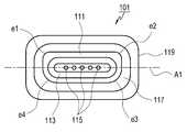
도 1에서 상기 전자 장치(10)로는 키보드 등의 입력 장치(15)가 배치된 본체(11)와, 디스플레이 장치 등의 출력 장치(17)가 배치된 디스플레이부(13)가 접철 가능하게 제공된 랩탑 컴퓨터(laptop computer)(10)가 예시되어 있다. 그러나 본 개시의 실시 예들에 따른 원리와 구성은 다른 전자 장치에도 쉽게 응용하여 적용될 수 있다. 본 개시에 따른 전자 장치는 커넥터를 포함하는 다양한 전자 장치일 수 있다. 예컨대, 스마트 폰(smartphone), 태블릿 PC(tablet personal computer), 이동 전화기(mobile phone), 화상 전화기, 전자북 리더기(e-book reader), 데스크탑 PC(desktop personal computer), 넷북 컴퓨터(netbook computer), PDA(personal digital assistant), PMP(portable multimedia player), MP3 플레이어, 모바일 의료기기, 전자 팔찌, 전자 목걸이, 전자 앱세서리(appcessory), 카메라(camera), 웨어러블 장치(wearable device), 전자 시계(electronic clock), 손목 시계(wrist watch), 가전 제품(home appliance)(예: 냉장고, 에어컨, 청소기, 오븐, 전자레인지, 세탁기, 공기 청정기 등), 인공 지능 로봇, TV, DVD(digital video disk) 플레이어, 오디오, 각종 의료기기(예: MRA(magnetic resonance angiography), MRI(magnetic resonance imaging), CT(computed tomography), 촬영기, 초음파기 등), 네비게이션(navigation) 장치, GPS 수신기(global positioning system receiver), EDR(event data recorder), FDR(flight data recorder), 셋톱 박스(set-top box), TV 박스(예를 들면, 삼성 HomeSyncTM, 애플TVTM, 또는 구글 TVTM), 전자 사전, 자동차 인포테인먼트(infotainment) 장치, 선박용 전자 장비(electronic equipment for ship, 예를 들면, 선박용 항법 장치, 자이로 콤파스 등), 항공 전자 장치(avionics), 보안 기기, 전자 의복, 전자 키, 캠코더(camcorder), 게임 콘솔(game consoles), HMD(head-mounted display), 평판표시장치(flat panel display device), 전자 액자, 전자 앨범, 통신 기능을 포함한 가구(furniture) 또는 건물/구조물의 일부, 전자 보드(electronic board), 전자 사인 입력장치(electronic signature receiving device) 또는 프로젝터(projector) 등의 다양한 장치들 중 하나 또는 그 이상의 조합일 수 있다. 본 개시에 따른 전자 장치는 전술한 기기들에 한정되지 않음은 당업자에게 자명하다.1, the
상기 접속 장치(100)는 제1 접속부, 예컨대, 상기 전자 장치(10)의 본체(11)를 이루는 본체 하우징(21)의 일부로 노출된 리셉터클(105)과, 상기 제1 접속부에 탈착 가능하게 제공된 제2 접속부, 예컨대, 커넥터(101)를 포함할 수 있다. 상기 커넥터(101)는, 외부의 전원 플러그, 예컨대, 충전기(109)에 연결된 케이블의 단부에 제공될 수 있다. 어떤 실시 예에서, 상기 커넥터(101)와 연결된 케이블의 다른 단부에 표준 USB 커넥터가 제공될 수 있다. 상기 리셉터클(105)은, 예를 들면, 상기 전자 장치(10) 본체 하우징(21) 표면으로 노출될 수 있다. 상기 리셉터클(105)를 통해 상기 커넥터(101)가 접속하므로, 상기 리셉터클(105)은 상기 본체 하우징(21)의 외부로 노출된(externally exposed) 표면의 일부에 형성될 수 있다.The
상기 커넥터(101)는 일면에 형성된 돌출부(111)를 구비할 수 있다. 상기 돌출부(111)에는 함몰 영역(113)이 형성되며, 상기 함몰 영역(113) 내에 접속 단자(115)들이 배열될 수 있다. 예컨대, 상기 커넥터(101)는 적어도 하나의 암 커넥터(female connector), 예컨대, 상기 접속 단자(115)를 포함할 수 있다. 상기 돌출부(111)는 상기 접속 단자(115)들이 배열된 영역, 예컨대, 상기 함몰 영역(113)을 적어도 부분적으로 둘러싸는 곡선 또는 폐곡선 형상으로 제공될 수 있다. 상기 돌출부(111)의 단부면으로부터 상기 함몰 영역(113)의 깊이는 상기 돌출부(111)가 상기 커넥터(101)의 일면으로부터 돌출된 높이보다 더 작을 수 있다. 상기 커넥터(101)는, 그의 일면에서 상기 돌출부(111)의 둘레를 적어도 부분적으로 둘러싸는 자성체(117)를 포함할 수 있다. 본 실시 예에 따른 접속 장치(100)의 커넥터(101)의 구성에서, 상기 자성체(117)는 하나의 극성으로 이루어진 자석을 포함할 수 있다. 상기 커넥터(101)는 절연체로 이루어진 하우징(119)을 포함할 수 있다. 상기 자성체(117)와 접속 단자(115)들은 상기 하우징(119)의 일면에 배치되고, 상기 돌출부(111)는 상기 하우징(119)과 일체형으로 이루어질 수 있다.The
어떤 실시 예에서, 상기 접속 장치(100)는 상기 돌출부(111)의 외주면을 적어도 일부 감싸게 제공된 접지 부재(112)를 더 포함할 수 있다. 상기 접지 부재(112)는 상기 돌출부(111)의 강도를 보강함과 아울러, 상기 커넥터(101)의 접지를 제공함으로써 상기 접속 장치(100)의 전기적 안정성을 강화할 수 있다.In some embodiments, the
도 2는 본 개시의 실시 예들 중 하나에 따른, 도 1의 접속 장치의 커넥터(101)의 정면도이다.Figure 2 is a front view of the
도 2를 더 참조하면, 암 커넥터를 이루는 복수의 상기 접속 단자(115)들은 일 방향, 예컨대, 상기 커넥터(101)의 횡방향을 따라 1열로 배열될 수 있다. 상기 접속 단자(115)들의 수는 상기 커넥터(101)의 용도, 예컨대, 충전이나 데이터 전송 등의 용도에 따라 다양하게 설정될 수 있다. 앞서 언급한 바와 같이, 상기 돌출부(111)는 상기 함몰 영역(113)을 둘러싸는 폐곡선 형태로, 상기 자성체(117)는 상기 돌출부(111)의 둘레를 둘러싸는 폐곡선 형태로 각각 제공될 수 있다. 상기 돌출부(111)를 형성함에 있어, 상기 접속 단자(115)들이 배열된 축(A1) 방향에 대하여 비대칭 형상으로 형성될 수 있다. 예컨대, 도 2에 도시된 바와 같이, 상기 돌출부(111)의 상면과 양 측면을 연결하는 모서리(e1, e2)들의 곡률은 하면과 양 측면을 연결하는 모서리(e3, e4)들의 곡률과 다르게 형성될 수 있다.2, the plurality of
도 3은 본 개시의 실시 예들 중 하나에 따른 접속 장치의 리셉터클을 나타내는 정면도이다. 도 4는 본 개시의 실시 예들 중 하나에 따른 접속 장치의 리셉터클을 나타내는 측 단면도이다.3 is a front view showing a receptacle of a connection device according to one of the embodiments of the present disclosure; 4 is a side cross-sectional view showing a receptacle of a connection device according to one of the embodiments of the present disclosure;
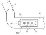
도 3과 도 4를 더 참조하면, 제1 접속부, 예컨대, 상기 리셉터클(105)은, 일면에 형성된 함몰부(151)를 구비할 수 있다. 상기 함몰부(151)에는 돌출 영역(153)이 형성되며, 상기 돌출 영역(153) 내에 접속 핀(155)들이 돌출된 상태로 배열될 수 있다. 예컨대, 상기 리셉터클(105)은 상기 함몰부(151)내에서 상기 돌출 영역(153)에 의해 적어도 일부 감싸진 적어도 하나의 수 커넥터(male connector)를 구비할 수 있다. 상기 함몰부(151)는 상기 돌출부(111)에, 상기 돌출 영역(153)은 상기 함몰 영역(113)에 각각 상응하게 형성될 수 있다. 상기 함몰부(151)는 상기 접속 핀(155)들이 배열된 영역, 예컨대, 상기 돌출 영역(153)을 둘러싸는 폐곡선 형상으로 제공될 수 있다. 상기 함몰부(151)의 바닥으로부터 상기 돌출 영역(153)이 돌출된 높이는 상기 함몰부(151)가 상기 리셉터클(105)의 일면으로부터 함몰된 깊이보다 더 작을 수 있다. 상기 리셉터클(105)의 일면에서 상기 함몰부(151)의 둘레를 따라 연장된 제2의 자성체(157)가 제공될 수 있다. 상기 제2 자성체(157)는 상기 커넥터(101)에 제공된 자성체(117)와 상응하여 인력을 발생시킬 수 있다. 예컨대, 상기 자성체(117)가 N극의 극성을 가진 자석이라면, 상기 제2 자성체(157)는 자성을 띌 수 있는 금속 물체 또는 S극의 극성을 가진 자석으로 이루어질 수 있다. 어떤 실시 예에서, 상기 자성체(117)가 자성을 띌 수 있는 금속 물체라면, 상기 제2 자성체(157)는 N극과 S극 중 어느 하나의 극성을 가진 자석으로 이루어질 수 있다.3 and 4, the first connection portion, for example, the
수 커넥터, 예컨대, 상기 접속 핀(155)들은 그 자체에 내장된 탄성체의 탄성력에 의해 일부분이 출몰 가능하게 이루어진 포고 핀(pogo pin)을 포함할 수 있다. 상기 접속 핀(155)들을 상기 돌출 영역(153)에 배치함에 있어, 상기 접속 핀(155)들의 단부는 상기 함몰부(151)의 내부에, 예컨대, 상기 리셉터클(105)의 하우징(159) 일면보다 더 깊게 배치될 수 있다. 상기 하우징(159)의 일면으로부터 상기 접속 핀(155)의 단부가 위치하는 깊이(d)는 실시 예에 따라 다양하게 설계될 수 있다. 상기 제2 자성체(157)의 자기력에 의해 다른 금속 물체가 상기 리셉터클(105)에 부착되더라도, 상기 접속 핀(155)들의 단부가 상기 함몰부(151)의 내부에 위치하므로, 상기 접속 핀(155)들 간의 단락을 방지할 수 있다. 마찬가지로, 도 2에 도시된 상기 커넥터(101)의 구성에서, 상기 접속 단자(115)들을 배치함에 있어, 상기 함몰 영역(113)의 바닥보다 상기 접속 단자(115)들을 더 깊게 배치하여, 이물질에 의한 상기 접속 단자(115)들 간의 단락을 방지할 수 있다.The male connector, for example, the connection pins 155 may include a pogo pin, which is partly protruded by the elastic force of the elastic body built in the male connector. When the connection pins 155 are arranged in the protruding
상기와 같은 리셉터클(105)을 상기 전자 장치(10)에 설치함에 있어, 상기 리셉터클(105)은 샤시(23)에 감싸진 상태로 상기 본체 하우징(21)의 내부에 고정될 수 있다. 상기 샤시(23)는 전기적인 차폐를 제공할 수 있으며, 또한 상기 리셉터클(105)을 상기 본체 하우징(21)의 내부에 고정하는 수단을 제공할 수 있다. 예컨대, 상기 샤시(23)는 고정핀(25)들을 구비함으로써, 상기 본체 하우징(21)의 내부에 배치된 회로 기판(29)에 고정될 수 있다.When the
도 5는 본 개시의 실시 예들 중 하나에 따른 접속 장치의 커넥터와 리셉터클이 결합하는 모습을 설명하기 위한 도면이다. 도 6은 본 개시의 실시 예들 중 하나에 따른 접속 장치의 커넥터와 리셉터클이 결합한 모습을 설명하기 위한 도면이다.Fig. 5 is a view for explaining how a connector of a connection device and a receptacle are engaged in accordance with one of the embodiments of the present disclosure; Fig. Fig. 6 is a view for explaining how the connector of the connection device and the receptacle are combined according to one of the embodiments of the present disclosure; Fig.
도 5와 도 6에 도시된 바와 같이, 상기 접속 장치(100)는 상기 커넥터(101)가 상기 리셉터클(105)에 결합하여 전기적인 연결을 제공할 수 있다. 상기 커넥터(101)의 돌출부(111)는 상기 리셉터클(105)의 함몰부(151)에, 상기 커넥터(101)의 함몰 영역(113)은 상기 리셉터클(105)의 돌출 영역(153)에 각각 맞물려 결속될 수 있다. 또한, 앞서 언급한 바와 같이, 상기 커넥터(101)의 자성체(117)와 상기 리셉터클(105)의 제2 자성체(157) 사이에 형성된 인력은 상기 커넥터(101)를 상기 리셉터클(105)에 더 견고하게 결속시킬 수 있다. 상기 자성체(117)와 제2 자성체(157)는 서로 접촉 가능하며, 직접 접촉하지 않더라도 상기 커넥터(101)를 상기 리셉터클(105)에 결속시키는 인력을 발생시킬 수 있다.As shown in FIGS. 5 and 6, the
상기 접속 단자(115)들은 상기 함몰 영역(113)보다 더 깊게, 상기 접속 핀(155)들은 상기 돌출 영역(153)에서 돌출된 상태로 설치됨은 앞서 언급한 바 있다. 상기 커넥터(101)가 상기 리셉터클(105)에 결합하면, 상기 돌출 영역(153)의 단부는 상기 함몰 영역(113)의 바닥에 닿는 위치까지 삽입될 수 있다. 상기 접속 핀(155)이 상기 돌출 영역(153)의 단부에서 돌출된 높이는 상기 함몰 영역(113)의 바닥으로부터 상기 접속 단자(115)들이 설치된 깊이보다 더 클 수 있다. 따라서 상기 커넥터(101)가 상기 리셉터클(105)에 결합한 상태에서, 상기 접속 핀(155)들은 각각 상기 접속 단자(115)들 중 하나와 안정적으로 접속할 수 있다.The
도 7은 본 개시의 실시 예들 중 다른 하나에 따른 접속 장치의 리셉터클을 나타내는 사시도이다. 도 8은 본 개시의 실시 예들 중 다른 하나에 따른 접속 장치의 리셉터클을 나타내는 분리 사시도이다.7 is a perspective view showing a receptacle of a connection device according to another of the embodiments of the present disclosure; 8 is an exploded perspective view showing a receptacle of a connection device according to another of the embodiments of the present disclosure;
도 7과 도 8에 도시된 바와 같이, 본 개시의 실시 예들 중 다른 하나에 따른 접속 장치의 리셉터클(205a)은 돌출 영역(153)을 감싸면서 진퇴 운동 가능하게 결합하는 커버 부재(253)를 더 구비하는 점에서 위에 언급된 실시 예의 리셉터클(105)과 차이가 있다. 본 실시 예에 따른 리셉터클(205a)을 설명함에 있어, 선행 실시 예를 통해 용이하게 이해할 수 있는 구성에 대해서는 도면의 참조번호를 동일하게 부여하거나 생략하고, 그 상세한 설명 또한 생략 될 수 있다.7 and 8, the
상기 커버 부재(253)는 상기 함몰부(151) 내에서 상기 돌출 영역(153)을 감싸게 제공되며, 상기 돌출 영역(153)이 돌출된 방향으로 진퇴 운동 가능하게 설치된다. 상기 커버 부재(253)의 내측단으로부터 상기 돌출 영역(153)이 수용되며, 상기 커버 부재(253)의 내측단 외주면에는 플랜지(253a)가 형성될 수 있다. 상기 커버 부재(253)의 단부 면에는 관통홀(253b)들이 형성되어 있다. 상기 관통홀(253b)들은 각각 상기 접속 핀(155)들 중 하나를 외부로 돌출시키는 통로를 제공할 수 있다.The
상기 리셉터클(205a)은 상기 커버 부재(253)를 지지하는 탄성 부재(259)들을 더 구비할 수 있다. 상기 탄성 부재(259)는 상기 돌출 영역(153) 상에서 상기 접속 핀(155)들과 나란하게 배치될 수 있다. 상기 탄성 부재(259)의 탄성력은 상기 커버 부재(253)가 상기 접속 핀(155)들을 수용하는 방향으로 작용하는 탄성력을 제공할 수 있다. 따라서 외력이 작용하지 않는다면, 예컨대, 상기 리셉터클(205a)에 커넥터가 결합하지 않은 상태에서, 상기 커버 부재(253)는 상기 접속 핀(155)들을 수용하여 보호할 수 있다.The
상기 리셉터클(205a)은 더미 플레이트(257)를 구비함으로써 상기 커버 부재(253)를 상기 함몰부(151) 내에 구속할 수 있다. 상기 더미 플레이트(257)는 상기 커버 부재(253)의 외주에서 상기 커버 부재(253)를 둘러싸게 배치되면서 상기 플랜지(253a)를 지지하는 상태로 상기 함몰부(151) 바닥에 고정될 수 있다. 이로써, 상기 커버 부재(253)는 상기 탄성 부재(259)로부터 상기 접속 핀(155)들을 수용하는 방향, 예컨대, 상기 함몰부로부터 이탈하는 방향으로 탄성력을 제공받으면서, 상기 더미 플레이트(257)에 지지되어 상기 함몰부(151) 내에 구속될 수 있다.The
상기 리셉터클(205a) 또한 고정핀(25)들을 구비함으로써, 회로 기판(29)에 고정될 수 있다.The
도 9와 도 10은 본 개시의 실시 예들 중 다른 하나에 따른 접속 장치의 커넥터와 리셉터클이 결합하는 모습을 각각 설명하기 위한 도면이다.Figs. 9 and 10 are views for respectively illustrating a state in which a connector of a connection device and a receptacle are engaged with each other according to another embodiment of the present disclosure.
도 9와 도 10을 더 참조하면, 상기 리셉터클(205a)은 상기 함몰부(151) 바닥에 형성된 회피홈(251)을 더 구비할 수 있다. 상기 회피홈(251)은 상기 함몰부(151)의 바닥에서 상기 돌출 영역(153)을 둘러싸게 형성되며, 상기 함몰부(151) 바닥보다 더 깊게 형성된다. 상기 커버 부재(253)가 상기 돌출 영역(153)을 수용한 상태로 결합하면 상기 커버 부재(253)의 플랜지(253a)는 상기 회피홈(251) 상에 위치될 수 있다. 예컨대, 상기 더미 플레이트(257)가 상기 함몰부(151) 바닥에 고정되면, 상기 플랜지(253a)는 상기 더미 플레이트(257)에 의해 상기 회피홈(151) 내에 구속될 수 있다.9 and 10, the
상기 커버 부재(253)가 상기 함몰부(151) 내에서 진퇴운동하면, 상기 플랜지(253a)는 상기 회피홈(251) 내에서 상기 커버 부재(253)와 함께 진퇴운동할 수 있다. 상기 커버 부재(253)가 상기 탄성 부재(259)의 탄성력에 의해 상기 함몰부(151)로부터 이탈하는 방향으로 이동할 때, 상기 플랜지(253a)는 상기 더미 플레이트(257)에 간섭되어 정지될 수 있다. 따라서 상기 커버 부재(253)는 상기 플랜지(253a)와 더미 플레이트(257)에 의해 상기 함몰부(151) 내에 구속된 상태로 유지될 수 있다.When the
도 9는 커넥터(101)가 상기 리셉터클(205a)에 결합하기 전의 모습을 도시하고 있다. 상기 커넥터(101)가 상기 리셉터클(205a)에 결합하기 전, 상기 커버 부재(253)에는 외력이 작용하지 않으므로, 상기 커버 부재(253)는 상기 탄성 부재(259)의 탄성력을 제공받아 상기 함몰부(151)로부터 이탈하는 방향으로 이동한 상태를 유지한다. 이때, 상기 플랜지(253a)가 상기 더미 플레이트(257)에 구속되어 있으므로, 상기 커버 부재(253)는 상기 함몰부(151) 내에 구속된 상태를 유지할 수 있다. 상기 플랜지(253a)가 상기 더미 플레이트(257)에 간섭된 상태에서, 상기 접속 핀(155)들은 상기 커버 부재(253)의 내부에 수용될 수 있다. 따라서 상기 접속 핀(155)들이 금속 물체 등의 이물질에 접촉하는 것을 방지할 수 있다.Fig. 9 shows a state before the
도 10은 상기 커넥터(101)가 상기 리셉터클(205a)에 결합한 모습을 도시하고 있다. 상기 커넥터(101)가 상기 리셉터클(205a)에 결합하면, 상기 커버 부재(253)는 상기 함몰 영역(113)의 바닥에 간섭되어 후퇴하고, 상기 플랜지(253a)는 상기 회피홈(251)의 내측으로 더 이동하게 된다. 상기 커버 부재(253)가 이동함에 따라, 상기 접속 핀(155)들은 상기 관통홀(253b)들을 통해 각각 상기 커버 부재(253)의 외부로 돌출한다. 상기 커버 부재(253)의 외부로 돌출한 상태에서 상기 접속 핀(155)들이 상기 접속 단자(115)들 중 하나에 각각 접속하여 전기적인 연결을 형성하게 된다. 상기 커넥터(101)가 상기 리셉터클(205a)에 결합한 상태에서, 상기 돌출부(111)는 상기 함몰부(151)에, 상기 돌출 영역(153)이 상기 함몰 영역(113)에 각각 맞물리며, 또한, 상기 커넥터(101)에 제공된 자성체(117)와 상기 리셉터클(205a)에 제공된 제2 자성체(157) 사이의 인력은 상기 커넥터(101)와 리셉터클(205a)을 안정적으로 고정시킬 수 있다.10 shows a state where the
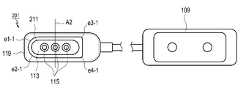
도 11은 본 개시의 실시 예들 중 또 다른 하나에 따른 접속 장치의 커넥터를 나타내는 정면도이다. 도 12는 본 개시의 실시 예들 중 또 다른 하나에 따른 접속 장치의 리셉터클을 나타내는 정면도이다. 도 13은 본 개시의 실시 예들 중 또 다른 하나에 따른 접속 장치의 커넥터와 리셉터클이 결합하는 모습을 설명하기 위한 도면이다. 도 14는 본 개시의 실시 예들 중 또 다른 하나에 따른 접속 장치의 커넥터와 리셉터클이 결합한 모습을 설명하기 위한 도면이다.11 is a front view showing a connector of a connection device according to yet another embodiment of the present disclosure; 12 is a front view showing a receptacle of a connection device according to yet another embodiment of the present disclosure; 13 is a view for explaining a state in which a connector of a connection device and a receptacle are engaged with each other according to another embodiment of the present disclosure; 14 is a view for explaining a state where a connector of a connection device and a receptacle are combined according to another embodiment of the present disclosure;
도 11 내지 도 14에 각각 도시된 커넥터(201)와 리셉터클(205b)을 설명함에 있어, 선행 실시 예를 통해 용이하게 이해할 수 있는 구성에 대해서는 도면의 참조번호를 선행 실시 예와 동일하게 부여하고 그 상세한 설명을 생략할 수 있다.In the following description of the
도 11과 도 12에 도시된 실시 예의 접속 장치에서, 상기 커넥터(201)는, 접속 단자(115)들이 배열된 축 방향의 수직 방향으로 연장된 축(A2)에 대하여 비대칭 형상의 돌출부(211)를 구비할 수 있다. 예컨대, 도 11에서, 상기 돌출부(211)의 좌측면과 상, 하면을 연결하는 모서리(e1-1, e2-1)들의 곡률은 우측면과 상, 하면을 연결하는 모서리(e3-1. e4-1)들의 곡률과 다르게 형성될 수 있다. 상기 커넥터(201)에 상응하는 리셉터클(205a) 또한 상기 돌출부(211)의 형상에 상응하는 함몰부(151) 형상을 가질 수 있다.11 and 12, the
상기와 같이, 커넥터의 돌출부와 리셉터클의 함몰부 형상을 서로 상응하게 하되, 비대칭 형상으로 형성함으로써, 사용자는 커넥터와 리셉터클의 결합 방향을 용이하게 인식할 수 있다.As described above, the protrusion of the connector and the shape of the depression of the receptacle are made to correspond to each other, but are formed in an asymmetrical shape, so that the user can easily recognize the direction of engagement between the connector and the receptacle.
한편, 선행 실시 예들의 커넥터와 리셉터클에서는 자성체가 돌출부 또는 함몰부의 둘레에 자성체가 배치된 구성이 예시되었으나, 본 개시의 구성이 이에 한정되지는 않는다.On the other hand, in the connector and the receptacle of the preceding embodiments, a configuration in which the magnetic body is disposed around the protruding portion or the depressed portion is exemplified, but the configuration of the present disclosure is not limited thereto.
예를 들면, 본 개시의 또 다른 실시 예에 따른 접속 장치에서, 상기 커넥터(201)의 돌출부(211)와 상기 리셉터클(205a)의 돌출 영역(153) 자체 또는 일부분이 자성체로 이루어질 수 있다. 또한, 자성체가 상기 돌출부(211)와 돌출 영역(153)에 내장될 수 있다. 본 개시의 실시 예들에 따른 접속 장치에 구비되는 자성체는, 앞서 언급한 바와 같이, 단일 극성의 자석(magnet) 또는 자기장 안에 놓였을 때 자성을 띠는 물체를 포함한다. 다만, 본 개시의 실시 예들에 따른 접속 장치에 자성체를 배치함에 있어, 커넥터와 리셉터클 각각에 자석과 자석 또는 자석과 자성을 띠는 물체를 배치하여 커넥터와 리셉터클 사이에 인력을 발생시킬 수 있다.For example, in the connection apparatus according to another embodiment of the present disclosure, the protruding
이상, 본 개시의 상세한 설명에서는 구체적인 실시 예에 관해서 설명하였으나, 본 개시의 범위에서 벗어나지 않는 한도 내에서 여러 가지 변형이 가능함은 당해 분야에서 통상의 지식을 가진 자에게 있어서 자명하다 할 것이다.While the present invention has been particularly shown and described with reference to exemplary embodiments thereof, it is to be understood that the invention is not limited to the disclosed embodiments, but, on the contrary, is intended to cover various modifications and equivalent arrangements included within the spirit and scope of the appended claims.
100: 접속 장치 101: 커넥터
111: 돌출부 113: 함몰 영역
115: 접속 단자 117: 자성체
105: 리셉터클 151: 함몰부
153: 돌출 영역 155: 접속 핀
157: 제2 자성체100: connection device 101: connector
111: protrusion 113: recessed area
115: connection terminal 117: magnetic substance
105: receptacle 151: depression
153: protruding area 155: connecting pin
157: second magnetic body
Claims (26)
Translated fromKorean하우징; 및
상기 하우징의 일부에 노출되도록 형성된 제1 접속부를 포함하고,
상기 제1 접속부는,
상기 하우징의 표면으로 노출되도록 형성된 환형(annular) 자성체(magnetic substance);
상기 환형 자성체에 의해 형성된(defined) 개구(opening)에 의해 적어도 일부 이루어진(at least partly formed) 함몰부(recessed portion); 및
상기 함몰부의 내부에 적어도 일부 포함된(contained) 적어도 하나의 수 커넥터(male connector)를 포함하는 전자 장치.
In an electronic device,
housing; And
And a first connection portion formed to be exposed to a part of the housing,
Wherein the first connecting portion comprises:
An annular magnetic substance formed to be exposed to the surface of the housing;
A recessed portion formed at least partly by an opening defined by the annular magnetic body; And
And at least one male connector at least partially contained within the recess.
상기 돌출 영역은 상기 수 커넥터의 적어도 일부를 감싸는 전자 장치.
2. The apparatus of claim 1, wherein the first connection portion further comprises a protruding area formed in the depression,
Wherein the protruding region surrounds at least a portion of the male connector.
상기 커버 부재가 진퇴운동함에 따라 상기 수 커넥터를 수용하거나 노출시키는 전자 장치.
3. The apparatus according to claim 2, wherein the first connecting portion further includes a cover member that engages with the protruding region so as to move back and forth,
And the male connector is received or exposed as the cover member moves back and forth.
상기 탄성 부재는 상기 수 커넥터를 수용하는 방향으로 작용하는 탄성력을 상기 커버 부재에 제공하는 전자 장치.
The connector according to claim 3, wherein the first connecting portion further comprises an elastic member for supporting the cover member,
Wherein the elastic member provides the cover member with an elastic force acting in a direction to receive the male connector.
상기 제1 접속부와 탈착 가능하게 접속하는 제2 접속부를 더 포함하는 전자 장치.
The method according to claim 1,
And a second connection portion detachably connected to the first connection portion.
상기 환형 자성체와 적어도 일부 접촉하는 자성체; 및
상기 수 커넥터에 상응하는 암 커넥터(female connector)를 포함하는 전자 장치.
The connector according to claim 5,
A magnetic body at least partially in contact with the annular magnetic body; And
And a female connector corresponding to said male connector.
6. The electronic device according to claim 5, wherein the second connection portion includes a protruding portion inserted into the depression.
8. The electronic device according to claim 7, wherein the magnetic body is provided adjacent to an end or an end of the protrusion.
The electronic device according to claim 1, wherein a plurality of said male connectors are arranged along one axial direction, and said depressions have an asymmetric shape with respect to an axis in which said male connectors are arranged.
The electronic device according to claim 1, wherein a plurality of said male connectors are arranged along one axial direction, and said depressions have an asymmetric shape with respect to an axis extending in a vertical direction of an axis in which said male connectors are arranged.
The electronic device according to claim 1, wherein a plurality of said male connectors are arranged and said depressions are in the form of a closed curve surrounding said array of male connectors.
The electronic device according to claim 1, wherein the annular magnetic body is in the form of a closed curve surrounding the depression.
하우징; 및
상기 하우징의 외부로 노출된(externally exposed) 표면의 일부에 제공된 접속부를 구비하고,
상기 접속부는,
함몰부;
상기 함몰부의 가장자리를 따라 연장된 자성체; 및
상기 함몰부 내에 형성된 적어도 하나의 수(male) 커넥터를 포함하는 전자 장치.
In an electronic device,
housing; And
And a connection provided on a portion of an externally exposed surface of the housing,
Wherein the connecting portion comprises:
Depression;
A magnetic body extending along an edge of the depression; And
And at least one male connector formed within said depression.
상기 접속부에 상응하게 결속되는 커넥터를 더 구비하고,
상기 커넥터는 상기 자성체에 상응하여 인력(attraction force)을 발생시키는 또 다른 자성체를 포함하는 전자 장치.
14. The method of claim 13,
Further comprising a connector coupled to the connection portion,
Wherein the connector further comprises another magnetic body for generating an attraction force corresponding to the magnetic body.
15. The electronic device according to claim 14, wherein at least one of the magnetic body of the connection portion and the magnetic body of the connector includes a magnet having one polarity.
상기 함몰부에 상응하게 맞물리는 돌출부;
상기 돌출부 상에 형성된 함몰 영역(recessed area); 및
상기 함몰 영역 내에 배열된 암 커넥터들을 구비하고,
상기 커넥터가 상기 접속부에 결속된 때, 상기 암 커넥터들이 상기 수 커넥터와 각각 접속하는 전자 장치.
15. The connector according to claim 14,
Protrusions corresponding to the depressions;
A recessed area formed on the protrusion; And
And a female connector arranged in the recessed region,
And wherein when the connector is engaged with the connection portion, the female connectors are respectively connected to the male connector.
17. The electronic device according to claim 16, wherein the female connectors are arranged along one axial direction, and the protrusions are formed as an electron having an asymmetric shape with respect to an axis in which the female connectors are arranged, Device.
17. The electronic device according to claim 16, wherein the connector further comprises a grounding member disposed at least partially surrounding the outer circumferential surface of the protrusion.
하우징;
하우징의 일부에 노출되도록 형성된 접속부; 및
상기 접속부에 탈착 가능하게 접속되는(engaged) 커넥터를 포함하고,
상기 접속부는,
상기 하우징의 표면 상에 노출되도록 형성된 자성체;
상기 자성체에 의해 적어도 일부 둘러싸인 함몰부(recessed portion); 및
상기 함몰부 내에 형성되는 돌출 영역; 및
상기 돌출 영역에 제공되는 적어도 하나의 접속 핀을 포함하는 전자 장치.
In an electronic device,
housing;
A connection portion formed to be exposed to a part of the housing; And
And a connector detachably connected to the connection,
Wherein the connecting portion comprises:
A magnetic body formed to be exposed on a surface of the housing;
A recessed portion at least partially enclosed by the magnetic body; And
A protruding region formed in the depression; And
And at least one connecting pin provided in the protruding region.
상기 접속부의 자성체에 인접하여 자력에 의해 끌릴 수 있는 물질을 포함하는 부재; 및
상기 접속 핀에 전기적으로 접촉하도록 구성된 전도성 부재를 포함하는 전자 장치.
20. The connector according to claim 19, wherein when the connector is connected to the connection portion,
A member adjacent to the magnetic body of the connection portion and including a material attractable by a magnetic force; And
And a conductive member configured to electrically contact the connection pin.
외부 전원 플러그와 전기적으로 연결된(coupled) 케이블; 및
상기 케이블의 일단에 연결된 커넥터를 포함하며,
상기 커넥터는,
실질적으로 환형(annular)이고, 자성 물질 또는 자석에 의하여 끌릴 수 있는 물질을 포함하는 돌출부;
상기 돌출부에 의하여 적어도 일부 형성된 함몰 영역; 및
상기 함몰 영역의 내부에 포함된 적어도 하나의 암 커넥터를 포함하는 전자 장치.
In an electronic device,
A cable that is electrically coupled to an external power plug; And
And a connector coupled to one end of the cable,
Wherein the connector comprises:
A protrusion substantially annular and comprising a magnetic material or magnet attractable material;
A recessed region formed at least partially by the projection; And
And at least one female connector contained within the recessed region.
22. The electronic device according to claim 21, wherein a plurality of said female connectors are arranged along one axial direction, and said projections have an asymmetrical shape with respect to an axis in which said female connectors are arranged.
22. The electronic device according to claim 21, wherein the plurality of female connectors are arranged along one axial direction, and the projections have an asymmetric shape with respect to an axis extending in the vertical direction of the axis in which the female connectors are arranged.
22. The electronic device of claim 21, wherein the protrusion is in the shape of a closed curve surrounding an array of the plurality of female connectors.
22. The electronic device according to claim 21, wherein the magnetic material or the material attractable by the magnet is disposed in the form of a closed curve surrounding the recessed region.
Priority Applications (3)
| Application Number | Priority Date | Filing Date | Title |
|---|---|---|---|
| KR1020130127650AKR20150047780A (en) | 2013-10-25 | 2013-10-25 | Electronic device with electrical connector |
| US14/294,617US20150118868A1 (en) | 2013-10-25 | 2014-06-03 | Electronic device having electric connector |
| EP20140172731EP2866304A1 (en) | 2013-10-25 | 2014-06-17 | Electronic device having electric connector |
Applications Claiming Priority (1)
| Application Number | Priority Date | Filing Date | Title |
|---|---|---|---|
| KR1020130127650AKR20150047780A (en) | 2013-10-25 | 2013-10-25 | Electronic device with electrical connector |
Publications (1)
| Publication Number | Publication Date |
|---|---|
| KR20150047780Atrue KR20150047780A (en) | 2015-05-06 |
Family
ID=50942200
Family Applications (1)
| Application Number | Title | Priority Date | Filing Date |
|---|---|---|---|
| KR1020130127650AWithdrawnKR20150047780A (en) | 2013-10-25 | 2013-10-25 | Electronic device with electrical connector |
Country Status (3)
| Country | Link |
|---|---|
| US (1) | US20150118868A1 (en) |
| EP (1) | EP2866304A1 (en) |
| KR (1) | KR20150047780A (en) |
Cited By (2)
| Publication number | Priority date | Publication date | Assignee | Title |
|---|---|---|---|---|
| WO2019083117A1 (en)* | 2017-10-26 | 2019-05-02 | 유학성 | Contact surface connection fixing device capable of power connection |
| US11034537B2 (en) | 2015-10-02 | 2021-06-15 | Omorobot Inc. | Positioning module and driving control device of carrier unit, including same |
Families Citing this family (21)
| Publication number | Priority date | Publication date | Assignee | Title |
|---|---|---|---|---|
| DE102014100119B4 (en)* | 2014-01-07 | 2022-07-14 | Infineon Technologies Ag | Magnet package and method for producing a magnet package |
| US9531118B2 (en)* | 2014-07-10 | 2016-12-27 | Norman R. Byrne | Electrical power coupling with magnetic connections |
| US9614320B2 (en)* | 2014-08-26 | 2017-04-04 | Google Inc. | Dongle for quick release |
| US10205291B2 (en) | 2015-02-06 | 2019-02-12 | Masimo Corporation | Pogo pin connector |
| BR112017016302B1 (en) | 2015-02-06 | 2022-12-06 | Masimo Corporation | PHYSIOLOGICAL SENSOR MANUFACTURING METHOD WITH EFFICIENT FLEXIBLE CIRCUIT |
| WO2017004086A1 (en)* | 2015-06-30 | 2017-01-05 | Zepp Labs, Inc. | Motion sensor in a sports instrument |
| RU176982U1 (en)* | 2015-09-01 | 2018-02-05 | Карен Ншанович Никоян | Individual sound reproduction tool for personal listening to audio information |
| EP3159978B1 (en)* | 2015-10-20 | 2020-11-25 | ITT Manufacturing Enterprises LLC | Receptacle, connector and connection interfaces with coupling mechanisms |
| US10177507B2 (en) | 2016-02-12 | 2019-01-08 | Norman R. Byrne | Electrical power load switch with connection sensor |
| CN107394490B (en)* | 2016-05-17 | 2021-01-26 | 富士康(昆山)电脑接插件有限公司 | Cable assembly with improved cable retention |
| MX371369B (en) | 2016-10-07 | 2020-01-28 | Norman R Byrne | Electrical power cord with intelligent switching. |
| GB2555493A (en)* | 2016-11-01 | 2018-05-02 | Roli Ltd | Electrical connector |
| CN106505363B (en)* | 2016-12-23 | 2019-11-26 | 深圳市泰科汉泽精密电子有限公司 | Magnetic pole button |
| CN108321634B (en)* | 2017-01-16 | 2021-02-23 | 富士康(昆山)电脑接插件有限公司 | Magnetic suction type connector combination |
| CN107221775A (en)* | 2017-07-05 | 2017-09-29 | 商洛市虎之翼科技有限公司 | A kind of magnetic-type attachment structure |
| US20190341709A1 (en)* | 2018-05-01 | 2019-11-07 | II Robert Shofner | Reinforced USB Cable |
| US10333249B1 (en)* | 2018-08-02 | 2019-06-25 | Shenzhen Tongyinhai Precision Electronics Co., Ltd | Electronic connector with magnetic element and data transmission line using same |
| US11424561B2 (en) | 2019-07-03 | 2022-08-23 | Norman R. Byrne | Outlet-level electrical energy management system |
| DE102019211043A1 (en)* | 2019-07-25 | 2021-01-28 | Sivantos Pte. Ltd. | Charging contact connection for a charger, mating contact connection, charging contact system and electrical device |
| US10658789B1 (en)* | 2019-07-29 | 2020-05-19 | Amphenol East Asia Electronic Technolog (Shen Zhen) Co., Ltd. | High speed connector with magnetic engagement mechanism |
| US20230420884A1 (en)* | 2022-06-24 | 2023-12-28 | Thales Avionics, Inc. | Floating pogo connectors for tablet computers of aircraft inflight entertainment systems and crew terminals |
Family Cites Families (12)
| Publication number | Priority date | Publication date | Assignee | Title |
|---|---|---|---|---|
| US2764747A (en)* | 1953-04-03 | 1956-09-25 | Henry J Modrey | Electrical connecting means and contact elements of such means |
| US5167516A (en)* | 1991-08-21 | 1992-12-01 | Foxconn International, Inc. | Connection with floating shield |
| CN1228891C (en)* | 2001-01-29 | 2005-11-23 | 蒂科电子公司 | High Density Plug Connectors for Twisted Pair Cables |
| GB0216448D0 (en)* | 2002-07-16 | 2002-08-21 | Mcleish Graham | Connector |
| TWM330608U (en)* | 2007-11-16 | 2008-04-11 | Wonten Technology Co Ltd | Electric connector |
| US7497693B1 (en)* | 2007-11-30 | 2009-03-03 | Hon Hai Precision Ind. Co., Ltd. | Electrical interconnection system using magnetic retention |
| US8388353B2 (en)* | 2009-03-11 | 2013-03-05 | Cercacor Laboratories, Inc. | Magnetic connector |
| FR2964501B1 (en)* | 2010-09-07 | 2013-05-17 | Schneider Electric Ind Sas | ASSEMBLY OF ELECTRICAL OUTLET |
| US8888500B2 (en)* | 2011-06-30 | 2014-11-18 | Apple Inc. | Robust magnetic connector |
| US9065205B2 (en)* | 2011-08-11 | 2015-06-23 | Apple Inc. | Connector insert having a cable crimp portion with protrusions and a receptacle having label in the front |
| US9780484B2 (en)* | 2011-08-11 | 2017-10-03 | Apple Inc. | Magnetic arrangements and labels for connectors |
| US8770986B2 (en)* | 2012-04-04 | 2014-07-08 | Harris Corporation | Devices, kits, and methods for supplementing retaining forces on matable devices such as electrical connectors |
- 2013
- 2013-10-25KRKR1020130127650Apatent/KR20150047780A/ennot_activeWithdrawn
- 2014
- 2014-06-03USUS14/294,617patent/US20150118868A1/ennot_activeAbandoned
- 2014-06-17EPEP20140172731patent/EP2866304A1/ennot_activeWithdrawn
Cited By (2)
| Publication number | Priority date | Publication date | Assignee | Title |
|---|---|---|---|---|
| US11034537B2 (en) | 2015-10-02 | 2021-06-15 | Omorobot Inc. | Positioning module and driving control device of carrier unit, including same |
| WO2019083117A1 (en)* | 2017-10-26 | 2019-05-02 | 유학성 | Contact surface connection fixing device capable of power connection |
Also Published As
| Publication number | Publication date |
|---|---|
| US20150118868A1 (en) | 2015-04-30 |
| EP2866304A1 (en) | 2015-04-29 |
Similar Documents
| Publication | Publication Date | Title |
|---|---|---|
| KR20150047780A (en) | Electronic device with electrical connector | |
| KR102348755B1 (en) | Tray, jig for separating tray and electronic device therof | |
| TWI812885B (en) | Electronic device, accessory for use with a portable electronic device, and magnetic alignment systems for electronic devices | |
| KR101924902B1 (en) | Connection device for portable terminal | |
| US9640921B2 (en) | Electrical connector and electronic device including the same | |
| CN103794943B (en) | Electrical connectors, sockets and electrical connector components | |
| EP3089282B1 (en) | Connector | |
| EP2960998B1 (en) | Connector device and electronic device with the same | |
| KR20160078069A (en) | An electric connector | |
| KR20150142388A (en) | Protecting cover | |
| KR20180010885A (en) | Connecting terminal device and electronic apparatus having the same | |
| US20160286015A1 (en) | Electronic device and connector thereof | |
| KR102090756B1 (en) | Wireless charging device for wearable device | |
| KR102251317B1 (en) | Structure for assembling housings and electronic device having it | |
| EP3853951B1 (en) | Shielded magnetic electronic connector | |
| WO2020192682A1 (en) | Mobile terminal, housing assembly, transmission device, and terminal system | |
| EP3086413A1 (en) | Separable connector structure coupled to device | |
| KR20160039999A (en) | Electronic device | |
| US11309649B2 (en) | Floating connector assembly | |
| US9853469B2 (en) | Charging system | |
| KR20150083567A (en) | Sim card connector and electronic apparatus including the same | |
| US20170070000A1 (en) | Power supply equipment of electronic device | |
| CN112994273A (en) | Terminal device and wireless transmitting assembly | |
| US20240213711A1 (en) | Electrical connector | |
| KR20150108605A (en) | Electronic device |
Legal Events
| Date | Code | Title | Description |
|---|---|---|---|
| PA0109 | Patent application | Patent event code:PA01091R01D Comment text:Patent Application Patent event date:20131025 | |
| PG1501 | Laying open of application | ||
| PC1203 | Withdrawal of no request for examination | ||
| WITN | Application deemed withdrawn, e.g. because no request for examination was filed or no examination fee was paid |