KR20150043353A - Signal processing for a capacitive sensor system with robustness to noise - Google Patents
Signal processing for a capacitive sensor system with robustness to noiseDownload PDFInfo
- Publication number
- KR20150043353A KR20150043353AKR1020157005001AKR20157005001AKR20150043353AKR 20150043353 AKR20150043353 AKR 20150043353AKR 1020157005001 AKR1020157005001 AKR 1020157005001AKR 20157005001 AKR20157005001 AKR 20157005001AKR 20150043353 AKR20150043353 AKR 20150043353A
- Authority
- KR
- South Korea
- Prior art keywords
- noise
- signal
- frequency
- operating frequency
- measurement value
- Prior art date
- Legal status (The legal status is an assumption and is not a legal conclusion. Google has not performed a legal analysis and makes no representation as to the accuracy of the status listed.)
- Granted
Links
Images


Classifications
- G—PHYSICS
- G01—MEASURING; TESTING
- G01D—MEASURING NOT SPECIALLY ADAPTED FOR A SPECIFIC VARIABLE; ARRANGEMENTS FOR MEASURING TWO OR MORE VARIABLES NOT COVERED IN A SINGLE OTHER SUBCLASS; TARIFF METERING APPARATUS; MEASURING OR TESTING NOT OTHERWISE PROVIDED FOR
- G01D5/00—Mechanical means for transferring the output of a sensing member; Means for converting the output of a sensing member to another variable where the form or nature of the sensing member does not constrain the means for converting; Transducers not specially adapted for a specific variable
- G01D5/12—Mechanical means for transferring the output of a sensing member; Means for converting the output of a sensing member to another variable where the form or nature of the sensing member does not constrain the means for converting; Transducers not specially adapted for a specific variable using electric or magnetic means
- G01D5/14—Mechanical means for transferring the output of a sensing member; Means for converting the output of a sensing member to another variable where the form or nature of the sensing member does not constrain the means for converting; Transducers not specially adapted for a specific variable using electric or magnetic means influencing the magnitude of a current or voltage
- G01D5/24—Mechanical means for transferring the output of a sensing member; Means for converting the output of a sensing member to another variable where the form or nature of the sensing member does not constrain the means for converting; Transducers not specially adapted for a specific variable using electric or magnetic means influencing the magnitude of a current or voltage by varying capacitance
- G—PHYSICS
- G01—MEASURING; TESTING
- G01R—MEASURING ELECTRIC VARIABLES; MEASURING MAGNETIC VARIABLES
- G01R27/00—Arrangements for measuring resistance, reactance, impedance, or electric characteristics derived therefrom
- G01R27/02—Measuring real or complex resistance, reactance, impedance, or other two-pole characteristics derived therefrom, e.g. time constant
- G01R27/26—Measuring inductance or capacitance; Measuring quality factor, e.g. by using the resonance method; Measuring loss factor; Measuring dielectric constants ; Measuring impedance or related variables
- G01R27/2605—Measuring capacitance
- G—PHYSICS
- G01—MEASURING; TESTING
- G01R—MEASURING ELECTRIC VARIABLES; MEASURING MAGNETIC VARIABLES
- G01R31/00—Arrangements for testing electric properties; Arrangements for locating electric faults; Arrangements for electrical testing characterised by what is being tested not provided for elsewhere
- G01R31/005—Testing of electric installations on transport means
- G—PHYSICS
- G01—MEASURING; TESTING
- G01R—MEASURING ELECTRIC VARIABLES; MEASURING MAGNETIC VARIABLES
- G01R35/00—Testing or calibrating of apparatus covered by the other groups of this subclass
- G01R35/005—Calibrating; Standards or reference devices, e.g. voltage or resistance standards, "golden" references
- G—PHYSICS
- G06—COMPUTING OR CALCULATING; COUNTING
- G06F—ELECTRIC DIGITAL DATA PROCESSING
- G06F3/00—Input arrangements for transferring data to be processed into a form capable of being handled by the computer; Output arrangements for transferring data from processing unit to output unit, e.g. interface arrangements
- G06F3/01—Input arrangements or combined input and output arrangements for interaction between user and computer
- G06F3/03—Arrangements for converting the position or the displacement of a member into a coded form
- G06F3/041—Digitisers, e.g. for touch screens or touch pads, characterised by the transducing means
- G06F3/044—Digitisers, e.g. for touch screens or touch pads, characterised by the transducing means by capacitive means
- G06F3/0445—Digitisers, e.g. for touch screens or touch pads, characterised by the transducing means by capacitive means using two or more layers of sensing electrodes, e.g. using two layers of electrodes separated by a dielectric layer
- H—ELECTRICITY
- H03—ELECTRONIC CIRCUITRY
- H03K—PULSE TECHNIQUE
- H03K17/00—Electronic switching or gating, i.e. not by contact-making and –breaking
- H03K17/94—Electronic switching or gating, i.e. not by contact-making and –breaking characterised by the way in which the control signals are generated
- H03K17/96—Touch switches
- H03K17/962—Capacitive touch switches
- H—ELECTRICITY
- H03—ELECTRONIC CIRCUITRY
- H03M—CODING; DECODING; CODE CONVERSION IN GENERAL
- H03M1/00—Analogue/digital conversion; Digital/analogue conversion
- H03M1/001—Analogue/digital/analogue conversion
- H—ELECTRICITY
- H03—ELECTRONIC CIRCUITRY
- H03K—PULSE TECHNIQUE
- H03K2217/00—Indexing scheme related to electronic switching or gating, i.e. not by contact-making or -breaking covered by H03K17/00
- H03K2217/94—Indexing scheme related to electronic switching or gating, i.e. not by contact-making or -breaking covered by H03K17/00 characterised by the way in which the control signal is generated
- H03K2217/96—Touch switches
- H03K2217/9607—Capacitive touch switches
Landscapes
- Engineering & Computer Science (AREA)
- Physics & Mathematics (AREA)
- General Physics & Mathematics (AREA)
- Theoretical Computer Science (AREA)
- General Engineering & Computer Science (AREA)
- Human Computer Interaction (AREA)
- Measurement Of Length, Angles, Or The Like Using Electric Or Magnetic Means (AREA)
- Electronic Switches (AREA)
- Position Input By Displaying (AREA)
- User Interface Of Digital Computer (AREA)
Abstract
Translated fromKoreanDescription
Translated fromKorean관련 출원에 대한 상호 참조Cross-reference to related application
본 출원은 2012년 8월 16일 출원된 미국 가출원 번호 61/684,009 호의 우선 이익을 주장하며, 상기 미국 가출원은 그 전체가 여기에 완전히 설명된 것처럼 본 출원에 참조로 통합된다.This application claims priority benefit from U.S. Provisional Application No. 61 / 684,009, filed August 16, 2012, which is incorporated herein by reference in its entirety as if fully set forth herein.
기술 분야Technical field
본 개시는 용량형 센서 시스템들을 위한 방법들 및 시스템들에 관한 것이며, 특히 이러한 시스템들에서의 신호 처리에 관한 것이다.The present disclosure relates to methods and systems for capacitive sensor systems, and more particularly to signal processing in such systems.
용량형 센서 시스템들은, 교류 전기장을 생성하고 이 전기장 내에 있는 센서 전극에서 한 사이클마다 얻어진 전위차(즉, 전압)를 측정함으로써 실현될 수 있다. 단일 전극, 또는 송신 전극 및 하나 이상의 수신 전극들이 사용될 수 있다. 이 전압은 센서 전극과 그의 전기적 환경 사이의 커패시턴스에 대한 척도인데, 즉 그 전압은 인간의 손가락이나 손과 같은 오브젝트들에 의해 영향을 받는다. 또한, 이 전압으로부터, 예를 들어, 손가락의 거리가 추론될 수 있다. 이 정보는 인간-기계 인터페이스들에 사용될 수 있다.Capacitive sensor systems can be realized by generating an alternating electric field and measuring the potential difference (i.e., voltage) obtained every cycle at the sensor electrode within this electric field. A single electrode, or a transmitting electrode and one or more receiving electrodes may be used. This voltage is a measure of the capacitance between the sensor electrode and its electrical environment, that is, the voltage is affected by objects such as human fingers or hands. Further, from this voltage, for example, the distance of the finger can be deduced. This information can be used for human-machine interfaces.
위에 언급한 원리에 따라 동작하는 종래의 시스템들이 갖는 문제점은 형광 램프들이나 USB 충전기들과 같은 전기 노이즈 소스들이 전기장에 영향을 줄 수 있다는 점이다. 따라서, 노이즈 환경에서 이 전압을 정확하고 신뢰성 있게 추정하는 데에는 어려움이 있다.A problem with prior art systems operating in accordance with the above-mentioned principles is that electrical noise sources such as fluorescent lamps or USB chargers can affect the electric field. Therefore, it is difficult to accurately and reliably estimate this voltage in a noisy environment.
다양한 실시예들에 따르면, 주파수 선택 노이즈의 환경들에서 동작 주파수의 자동 적응을 구현하는 용량형 센서 시스템이 제공된다. 실시예들에 따른 용량형 센서는: 교류 전기장을 센서에 제공하도록 구성된 송신 전극; 상기 교류 전기장의 변동들을 검출하기 위한 하나 이상의 수신 전극들; 및 노이즈 전력과 같은 노이즈 측정값의 검출에 응답하여 상기 교류 전기장의 동작 주파수를 조정하도록 구성된 어댑티브 주파수 조정 유닛을 포함한다. 몇몇 실시예들에서, 상기 어댑티브 주파수 조정 유닛은 포텐셜 동작 주파수들에서 복수의 노이즈 전력들을 결정하고 그리고 새로운 동작 주파수를 선택하도록 구성된다.According to various embodiments, a capacitive sensor system is provided that implements automatic adaptation of the operating frequency in environments of frequency selective noise. A capacitive sensor according to embodiments includes: a transmitting electrode configured to provide an alternating electric field to a sensor; At least one receiving electrode for detecting variations of the alternating electric field; And an adaptive frequency adjustment unit configured to adjust an operating frequency of the alternating electric field in response to detection of a noise measurement value such as noise power. In some embodiments, the adaptive frequency adjustment unit is configured to determine a plurality of noise powers at potential operating frequencies and to select a new operating frequency.
실시예들에 따른, 노이즈 강건성을 용량형 감지 시스템에 제공하는 방법은: 복수의 포텐셜 동작 송신 주파수들을 정의하고; 상기 포텐셜 동작 주파수들의 각각에 대응하는 대응 노이즈 측정값을 결정하고; 상기 복수의 포텐셜 동작 송신 주파수들 중 하나에서 상기 용량형 감지 시스템을 동작시키고; 상기 동작 주파수에서 동작 노이즈 측정값을 측정하고; 그리고 상기 측정된 동작 노이즈 측정값에 응답하여 새로운 동작 주파수를 선택하는 것을 포함한다.A method of providing noise robustness to a capacitive sensing system, according to embodiments, includes: defining a plurality of potential operational transmit frequencies; Determine corresponding noise measurements corresponding to each of the potential operating frequencies; Operating the capacitive sensing system at one of the plurality of potential operational transmit frequencies; Measuring an operating noise measurement at said operating frequency; And selecting a new operating frequency in response to the measured operating noise measurement value.
실시예들에 따른 용량형 센서 시스템은: 교류 전기장을 센서에 제공하도록 구성된 송신 전극; 상기 교류 전기장의 변화들을 검출하기 위한 하나 이상의 수신 전극들; 및 상기 용량형 센서 시스템을 직접 샘플링 및 동기화 복조를 갖는 진폭 변조 시스템으로서 모델링함에 따라 상기 교류 전기장의 동작 주파수를 조정하도록 구성된 어댑티브 주파수 조정 유닛을 포함한다. 몇몇 실시예들에서, 상기 어댑티브 주파수 조정 유닛은 포텐셜 동작 주파수들에서 복수의 노이즈 측정값들을 결정하고, 그리고 상기 복수의 노이즈 측정값들의 최소값 또는 최대값에 대응하는 동작 주파수를 선택하도록 구성된다.A capacitive sensor system according to embodiments includes: a transmitting electrode configured to provide an alternating electric field to a sensor; At least one receiving electrode for detecting changes of the alternating electric field; And an adaptive frequency adjustment unit configured to adjust the operating frequency of the alternating electric field by modeling the capacitive sensor system as an amplitude modulation system with direct sampling and synchronization demodulation. In some embodiments, the adaptive frequency adjustment unit is configured to determine a plurality of noise measurements at potential operating frequencies, and to select an operating frequency corresponding to a minimum or maximum value of the plurality of noise measurements.
실시예들에 따른 센서 시스템은, 노이즈 신호를 수신하는 신호 처리 유닛과 결합되고 노이즈에 노출되어 있는 교류 전기장 센서 배열을 포함하고, 여기서 상기 신호 처리 유닛은 상기 노이즈 신호를 디지털 신호로 변환하고, 상기 신호 처리 유닛은 또한 샘플링된 신호를 (-1)k과 곱한 다음 - k는 이산 시간을 나타냄 - 저역-통과 필터링하고, 그 다음에 R 인자로 데시메이션하고 그리고 추가 저역-통과 필터링하여 상기 샘플링된 신호를 복조하도록 구성된다. 상기 신호 처리 유닛은 또한 상기 처리된 신호로부터 거리 추정, 포지셔닝 또는 제스처 인식을 수행하도록 동작 가능할 수 있다. 상기 교류 전기장은 펄스 신호에 의해 발생될 수 있다.A sensor system according to embodiments includes an AC electric field sensor arrangement coupled to a signal processing unit for receiving a noise signal and exposed to noise wherein the signal processing unit converts the noise signal to a digital signal, The signal processing unit also multiplies the sampled signal by (-1)k , then k represents discrete time-low-pass-filtered, then decimates by R factor, and further low-pass- And to demodulate the signal. The signal processing unit may also be operable to perform distance estimation, positioning or gesture recognition from the processed signal. The alternating electric field may be generated by a pulse signal.
본 개시의 이들 및 다른 특징들은 첨부 도면들과 결합된 이하의 설명을 참조하면 보다 완전하게 이해될 수 있을 것이다. 하지만, 본 개시의 다양한 실시예들 및 이들의 다수의 특정 세부 사항들을 나타내는 다음의 설명은 예시로서 주어지고 한정하고자 하는 것이 아님을 이해해야 한다. 많은 대체들, 수정들, 추가들 및/또는 재배열들이 본 개시의 사상을 벗어나지 않는 본 개시의 범위 내에서 행해질 수 있고, 본 개시는 모든 이러한 대체들, 수정들, 추가들 및/또는 재배열들을 포함한다.These and other features of the present disclosure may be more fully understood by reference to the following description taken in conjunction with the accompanying drawings. It should be understood, however, that the following description, which sets forth various embodiments of the disclosure and many of the specific details thereof, is given by way of illustration and not by way of limitation. It should be understood that many alternatives, modifications, additions, and / or rearrangements may be made within the scope of this disclosure without departing from the spirit of the disclosure, and this disclosure is to be accorded the broadest interpretation so as to encompass all such alternatives, modifications, .
본 발명에 따르면, 주파수 선택 노이즈의 환경들에서 동작 주파수의 자동 적응을 구현하는 개선된 용량형 센서 시스템이 제공된다.SUMMARY OF THE INVENTION In accordance with the present invention, an improved capacitive sensor system is provided that implements automatic adaptation of operating frequencies in environments of frequency selective noise.
첨부되고 본 명세서의 일부를 형성하는 도면들은 본 개시의 특정 측면들을 묘사하기 위해 포함된다. 도면들에 도시된 특징들은 반드시 실척으로 도시된 것은 아님을 유의해야 한다. 본 개시 및 그 이점들은 첨부 도면들과 결합된 이하의 설명을 참조하면 보다 완전하게 이해될 수 있을 것이며, 도면들에서 같은 참조 번호들은 동일한 기능들을 가리킨다.
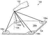
도 1은 예시적인 용량형 감지의 개략도를 도시한다.
도 2는 예시적인 용량형 센서의 개략도를 도시한다.
도 3은 예시적인 노이즈 및 노이즈 감소를 도시한 도면이다.
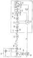
도 4는 예시적인 용량형 센서의 개략도를 도시한다.
도 5는 도 4의 예시적인 용량형 센서를 보다 상세하게 도시한 도면이다.
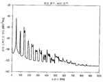
도 6은 예시적인 노이즈 전력 스펙트럼 밀도를 도시한 도면이다.
도 7은 노이즈 입력 신호의 예시적인 전력 스펙트럼 밀도를 도시한 도면이다.
도 8은 샘플링된 노이즈 입력 신호의 예시적인 전력 스펙트럼 밀도를 도시한 도면이다.
도 9는 관심 신호들을 나타내는 개략적인 스펙트럼을 도시한 도면이다.
도 10은 실시예들에 따른 프로세스 흐름을 도시한 도면이다.
도 11은 실시예들에 따른 예시적인 시스템 구현 방법들을 도시한 도면이다.The accompanying drawings, which are incorporated in and form a part of this specification, are included to illustrate certain aspects of the disclosure. It is noted that the features shown in the drawings are not necessarily drawn to scale. The present disclosure and advantages thereof may be more fully understood by reference to the following description taken in conjunction with the accompanying drawings, in which like reference numerals designate like features.
Figure 1 shows a schematic diagram of an exemplary capacitive sensing.
Figure 2 shows a schematic diagram of an exemplary capacitive sensor.
3 is a diagram illustrating exemplary noise and noise reduction.
Figure 4 shows a schematic view of an exemplary capacitive sensor.
Figure 5 is a more detailed view of the exemplary capacitive sensor of Figure 4;
6 is a diagram illustrating an exemplary noise power spectral density.
7 is a diagram illustrating an exemplary power spectral density of a noise input signal.
8 is a diagram illustrating an exemplary power spectral density of a sampled noise input signal.
9 is a diagram showing a schematic spectrum representing interest signals.
10 is a diagram illustrating a process flow according to embodiments.
11 is a diagram illustrating exemplary system implementation methods in accordance with embodiments.
본 개시 및 다양한 특징들 및 그의 유리한 세부 사항들은, 첨부 도면들에 도시되고 이하 상세하게 설명된 예시적인 - 그러므로 비제한적인 - 실시예들을 참조하여 보다 상세하게 설명된다. 하지만, 바람직한 실시예들을 나타내는 상세한 설명 및 특정 예들은 예시로서만 주어지고 한정하고자 하는 것이 아님을 이해해야 한다. 알려져 있는 프로그래밍 기술들, 컴퓨터 소프트웨어, 하드웨어, 운영 플랫폼들 및 프로토콜들의 설명들은 상세한 본 개시를 쓸데없이 애매하게 하지 않도록 생략될 수 있다. 기본적인 발명의 개념의 사상 및/또는 범위 내의 다양한 대체들, 수정들, 추가들 및/또는 재배열들은 본 개시로부터 이 기술분야의 당업자들에게 명백하게 될 것이다.The present disclosure and various features and advantageous details thereof are described in more detail with reference to the exemplary and thus non-limiting examples shown in the accompanying drawings and described in detail below. It should be understood, however, that the detailed description and specific examples, while indicating preferred embodiments, are given by way of illustration only and not by way of limitation. The descriptions of known programming techniques, computer software, hardware, operating platforms and protocols may be omitted so as not to obscure the present disclosure in detail. Various alternatives, modifications, additions and / or rearrangements within the spirit and / or scope of the basic inventive concept will become apparent to those skilled in the art from this disclosure.
이제 도면들, 특히 도 1을 보면, 교류 전기장의 평가를 위한 예시적인 센서 전극 배열(100)이 도시되어 있다. 센서 전극 배열은 복수의 수신 전극들(106a 내지 106e) 및 하나 이상의 송신 전극들(104)을 포함한다. 하나 이상의 수신 전극들(106a 내지 106e)은 전형적으로 송신 전극(104) 위(above)에 층으로 배열되고, 송신 전극과 수신 전극들 사이에는 절연층(도시되지 않음)이 배열되어 있다. 센서 전극 배열(100)은 손가락(102)과 같은 오브젝트가 교류 전기장에 미치는 영향을 결정하도록 구성된다. 이에 따라, 손가락(102)과 센서 전극 배열 사이의 거리(108)가 결정될 수 있다.Referring now to the drawings, and in particular to Figure 1, there is shown an exemplary
보다 특히, 다양한 실시예들에 따르면, 프론트 엔드 디바이스는 수신 전극들과 손가락(GND) 사이의 커패시턴스를 측정하여 손가락(102)과 센서 배열 사이의 거리를 추정한다. 용량형 전압 분할기의 포텐셜 변화들은 교류 전압에 의해 여기된다.More particularly, according to various embodiments, the front end device measures the capacitance between the receiving electrodes and the finger (GND) to estimate the distance between the
이는 도 2를 참조하여 개략적으로 설명된다. 특히, 도 2는 송신기 전극(ETX) 및 수신기 전극(ERX)을 갖는 용량형 센서 시스템(200)의 단면 위의 거리 xo에 있는 사람의 손가락(102)을 보여준다. ETX는 직사각형 펄스 트레인 전압원(202)을 이용하여 여기되고, 여기서 ETX와 그라운드(GND) 사이의 소스 저항 RS 및 커패시턴스 CTX는 저역-통과 필터를 형성한다. 직사각형 펄스 트레인 전압은 전형적으로 40-140 kHz의 주파수를 갖는다. ERX와 GND 사이의 가변 커패시턴스 Cf는 ERX와 손가락(102) 사이의 커패시턴스에 의해 지배되며, 이 ERX와 손가락(102) 사이의 커패시턴스는 손가락과 ERX 사이의 거리 xo에 의존한다. Cf 및 ETX와 ERX 사이의 일정한 커패시턴스 Cs는 용량형 전압 분할기(204)를 만든다. 따라서, 전압 Vf는 xo의 함수이다.This is schematically described with reference to Fig. In particular, Figure 2 shows a
센서 시스템의 기본적인 이해를 위해 별로 중요하지 않은 추가 커패시턴스들은 도면에서 생략되었음에 유의한다. 또한, 커패시턴스 Cf는 거리 xo에 의존할 뿐만 아니라 손가락 끝의 3차원 위치, 손의 방향, 손의 크기 등에 의존한다.Note that additional capacitances, which are not of significant importance for a basic understanding of the sensor system, are omitted from the drawings. In addition, the capacitance Cf depends not only on the distance xo but also on the three-dimensional position of the fingertip, the direction of the hand, the size of the hand, and the like.
도 3은 집적 프론트 엔드 디바이스의 출력 신호들(300, 302)을 도시한다. 출력 신호(300)는 실시예들에 따른, 노이즈 개선, 즉 자동 주파수 적응(automatic frequency adaptation)이 없는 출력 신호를 나타내는 반면, 출력 신호(302)는 실시예들에 따라 자동 주파수 적응이 이루어진 출력이다. 도시된 바와 같이, 304에서 형광 램프와 같은 노이즈 소스가 스위칭 온(on)된다. 센서 신호(307a)는 노이즈의 영향을 보여주지만, 신호(307b)는 깨끗하고 노이즈가 없는 신호를 보여준다.3 shows the
다양한 실시예들에 따라, 아래에 보다 상세히 설명되는 바와 같이, 센서 전극 배열에 대한 노이즈 강건성(noise robustness)은 예를 들어, 센서 신호들의 직접적인 평가를 위한 집적 프론트 엔드 회로에 제공될 수 있다. 다양한 실시예들에 따르면, 채널 노이즈는 자동으로 평가될 수 있고, 최적의 동작 주파수들이 선택될 수 있다.According to various embodiments, the noise robustness of the sensor electrode arrangement, as described in more detail below, may be provided to an integrated front-end circuit for direct evaluation of sensor signals, for example. According to various embodiments, the channel noise can be automatically evaluated and optimal operating frequencies can be selected.
도 4는 다양한 실시예들에 따른 예시적인 용량형 센서(400)를 도시한다. 전압원(VTX)의 출력은 403에서 저역-통과 필터링되고 그리고 용량형 전압 분할기(404)를 구동한다. 수신 전극 ERX는 임의의 버퍼(406), 아날로그 대역-통과 필터(408), 및 직접적인 샘플링을 수행하는 아날로그-디지털 컨버터(ADC)(410)에 연결될 수 있다. ADC(410)는 전압원과 동기화되어 각 송신기 주기 동안 두 개의 샘플들을 채취할 수 있다. ADC의 출력은 디지털 신호 처리(DSP) 유닛(412)에 공급된다. 아래에 더욱 상세히 설명되는 바와 같이, DSP(412)는 노이즈 조건들에도 불구하고 최적의 동작 주파수를 선택하도록 제어 경로(414)를 통해 발진기(VTX)를 제어한다.FIG. 4 illustrates an exemplary
도 5는 도 4의 용량형 센서의 통신 이론 모델을 도시한다. 특히, 아래에 보다 상세히 설명되는 바와 같이, 용량형 센서는 직접 샘플링 방식의 진폭 변조 시스템으로 모델링될 수 있다. 예를 들어, 예시적인 샘플링 주파수는 송신 신호(VTX) 주파수의 두 배일 수 있다. 예를 들어, fTX가 100kHz이면, fs = l/Ts = 2fTX = 200kHz이다. 다른 주파수들이 가능할 수도 있다.Figure 5 shows a communication theoretical model of the capacitive sensor of Figure 4; In particular, as will be described in more detail below, the capacitive sensor can be modeled as a direct sampling amplitude modulation system. For example, the exemplary sampling frequency may be twice the transmit signal (VTX ) frequency. For example, if fTX is 100 kHz, fs = 1 / Ts = 2 fTX = 200 kHz. Other frequencies may be possible.
디지털 신호 처리 블록(412)은 다양한 실시예들에 따라, 디지털 복조(506), R에 의한 다운샘플링(예를 들어, R=1000일 때 fs' = 200Hz로 다운샘플링), 즉 저역-통과 필터링(508)과 이후의 데시메이션(510), 저역 통과 필터링(512), 주파수 종속 신호 조정(514), 및 이후의 포지셔닝 및 제스처 인식(516)을 실행할 수 있다.A digital
보다 특히, 저역-통과 필터(403)의 출력, 즉 저역-통과 필터링된 직사각형 펄스 트레인(402)이 캐리어 신호 c(t)로서 모델링될 수 있으며, 여기서 t는 연속 시간을 나타낸다. 캐리어 신호 c(t)는 커패시턴스 Cf(도 2, 도 4)의 함수인 [m0+m(t)]를 가지고 변조되어(501) y(t)를 산출한다.More specifically, the output of the low-
502에서, 신호 y(t)는 랜덤 노이즈 e(t)를 그에 부가했다. 랜덤 노이즈 e(t)는 예를 들어 형광등이나 다른 소스들로부터의 노이즈를 나타낼 수 있다. 결과로 생긴 노이즈 신호 z(t) = y(t) + e(t)는 이산 시간들(k*Ts)에서 샘플링되며(504), 여기서 Ts = 1/(2*fTX)는 송신기 주파수(fTX)의 두 배의 역이고, k=0,1,2,...는 이산 시간 인덱스이다.At 502, the signal y (t) has added thereto a random noise e (t). The random noise e (t) may represent, for example, a fluorescent light or noise from other sources. The resulting noise signal z (t) = y (t) + e (t) is sampled 504 at discrete times (k * Ts ), where Ts = 1 / (2 * fTX ) Is twice the frequency (fTX ), and k = 0, 1, 2, ... is the discrete time index.
ADC(410)는 시간-이산 신호를 디지털 도메인으로 변환한다. 그리고 나서 ADC 출력 z(k)는 DSP(412)에 의해 처리된다. 도시된 예에서, 신호 z(k)는 506에서 (-1)k과의 곱에 의해 디지털로 복조되고, 저역-통과 필터링되고(508), 인자 R(전형적으로 400-1400)에 의해 데시메이팅되고(decimated)(510), 그리고 손의 움직임의 주파수들(전형적으로 0-20Hz)만을 포함하도록 재차 저역-통과 필터링된다(512). 그리고 나서 그것은 거리 추정, 포지셔닝 또는 제스처 인식(516)과 같은 추가 처리에 사용된다. 자동 주파수 적응(automatic frequency adaptation; AFA) 모듈(518)은 데시메이터 출력을 수신하고, 그리고 주파수 선택적 노이즈에 대한 강건성을 제공하기 위해 신호를 조정하기 위한 제어 신호들을 제공한다.
도 6은 외부 노이즈 소스의 예로서의 형광 램프의 전력 스펙트럼 밀도(Power Spectral Density; PSD)를 도시한다. 시스템의 ADC 입력부에서 측정된 이 PSD는 고조파(harmonic) 협대역 방출을 보여준다. 시스템의 TX 주파수 fTX(즉, 캐리어 주파수)가 이 방출들 중 하나의 방출을 충족시키면, 상기 시스템은 사용자의 입력을 인식함에 있어 영향을 받는다. 도 7은 형광 램프와 같은 외부 노이즈 소스의 보다 상세한 스펙트럼을 도시한다. 또한, 스펙트럼은 예시적인 70 kHz의 주파수를 갖는 시스템의 직사각형 TX 신호의 별개의 피크들을 포함한다. 이 예에서는, fTX 및 그의 고조파들은 노이즈 소스의 방출들과 일치하지 않는다.Figure 6 shows the power spectral density (PSD) of a fluorescent lamp as an example of an external noise source. This PSD measured at the ADC input of the system shows harmonic narrowband emissions. If the system's TX frequency fTX (i.e., carrier frequency) meets the emission of one of these emissions, the system is affected in recognizing the user's input. Figure 7 shows a more detailed spectrum of an external noise source such as a fluorescent lamp. The spectrum also includes distinct peaks of a rectangular TX signal of a system having an exemplary 70 kHz frequency. In this example, fTX and its harmonics are inconsistent with the emissions of the noise source.
아날로그 대역-통과 필터(408)의 기울기(steepness)에 따라, fTX의 배수들에서의 방출들도 시스템에 영향을 미칠 것이다. 예를 들어, 도 8은 불충분하게 가파른 아날로그 대역-통과 필터 이후의 샘플링에 의해 (200-3*47)=59 kHz에서 200 kHz 대역에 섞인(folded) 도 6의 PSD에서의 47 kHz 노이즈 피크의 제 3 고조파를 보여준다.Depending on the steepness of the analog band-
다운-샘플링(510) 이후에 얻어진 스펙트럼이 도 9에 개략적으로 도시되어 있다. 다운-샘플링된 신호의 스펙트럼은 도 8의 노이즈 피크들에 비해 좁다. 외부 노이즈는 이제 PSD에서 평탄하다. 외부 노이즈 전력(908)의 추정치는 예를 들어 70-90 Hz의 주파수 대역에 있다.The spectra obtained after down-sampling 510 are schematically shown in Fig. The spectrum of the down-sampled signal is narrow compared to the noise peaks of FIG. External noise is now flat on the PSD. The estimate of the
다운샘플링 이후의 스펙트럼의 성분들은, a) 원하는 신호(0-20 Hz)(902), b) 비선형 시스템 구성요소들로 인해 캐리어 상에서 변조되어진 공지의 저주파 노이즈, 예컨대 전원(mains)(즉, 50 또는 60 Hz 라인) 전압(904), 및 c) 형광등과 같은 고주파 소스들을 나타내는 노이즈 플로어(floor)(906)이다. 노이즈 플로어(906)는 관심 주파수들에서 거의 평탄하고, 그리고 고주파(HF) 노이즈가 전혀 존재하지 않으면 비교적 낮다.The components of the spectrum after downsampling are: a) the desired signal (0-20 Hz) 902; b) known low frequency noise modulated on the carrier due to nonlinear system components, such as mains Or 60 Hz line)
이 노이즈 플로어(906)는 현재의 fTX가 노이즈 주파수 대역 안에 있으면 상승할 것이며, 그 노이즈 주파수 대역폭은 (전형적인 경우에) 복조 신호의 샘플링 레이트를 초과한다. 따라서, HF 노이즈 전력은 대역(908)에서처럼, 원하는 신호(902)나 알려진 저주파 노이즈(904)를 포함하지 않는 임의의 주파수 대역의 다운-샘플링된 신호에서 측정될 수 있다.This
다양한 실시예들에 따르면, 자동 주파수 적응(AFA) 유닛(518)은 이 노이즈 전력 측정 기술을 이용한다. 하지만, 다른 노이즈 측정들도 가능하다.According to various embodiments, an automatic frequency adaptation (AFA)
이제 도 10을 보면, 실시예들에 따른 예시적인 프로세스가 도시되어 있다. 1002에서, AFA(518)는 시스템의 시동시 또는 어떠한 사용자 행동도 인식되지 않으면(또는 임의의 다른 적당한 이벤트시), TX 주파수들의 소정 세트(1004)(예컨대, 40-140 kHz 범위 내의 8개의 주파수들)에서의 일련의 노이즈 전력 측정들을 수행한다. 예를 들어, 도 9에 도시된 908과 같은 대역에서 측정들이 수행된다. 각각의 측정된 노이즈 전력들은 전용 어레이(1006)에 세이브된다. 종료 기준(exit criterion)시, 예를 들어 세트(1004)의 모든 주파수들이 조사되었거나 사용자의 행동 시작이 인식되면, 시스템은 고정 TX 주파수(fTX)에서 동작한다. 이 주파수는 노이즈 전력들의 어레이(1006) 내의 최저값을 보여주는 주파수로 선택될 수 있다.Turning now to Fig. 10, an exemplary process according to embodiments is shown. At 1002, the
사용자가 행동하는 동안, AFA는 현재의 동작 주파수 fTX에서 주기적으로 노이즈 전력을 측정한다(1008). 노이즈 전력의 값이 특정 문턱치를 초과하면, TX 주파수 fTX는 보다 낮은 노이즈 전력을 갖는 다른 주파수로 조정된다. 예를 들어, 몇몇 실시예들에서, 주파수는 노이즈 전력들의 어레이(1006) 내의 최저값에 대응하는 주파수로 변경된다.While the user is acting, the AFA periodically measures the noise power at the current operating frequency fTX (1008). If the value of the noise power exceeds a certain threshold, the TX frequency fTX is adjusted to a different frequency with a lower noise power. For example, in some embodiments, the frequency is changed to a frequency corresponding to the lowest value in the array of noise powers 1006.
부가적으로, 몇몇 실시예들에서, AFA는 DSP의 주파수 종속 조정값들, 예컨대 다운-샘플링의 레이트를 트리거할 수 있으며, 그리고 이후의 처리 단계들에 주파수 독립 데이터를 제공하도록 조정할 수 있다. 신호 신뢰도에 관한 정보도 또한 DSP 블록들에 전달된다. 거기에서 예를 들어 필터 이득들이 신호 신뢰도에 따라 조정된다. 또한, 특정 몇몇의 기능성 또는 그 밖의, 예컨대 확률 파라미터들을 트리거하기 위해 확률 문턱치들의 신호 레벨 문턱치들이 조정될 수 있다.Additionally, in some embodiments, the AFA may trigger the frequency dependent adjustment values of the DSP, e.g., the rate of down-sampling, and may be adjusted to provide frequency-independent data to subsequent processing steps. Information about signal reliability is also conveyed to the DSP blocks. There, for example, filter gains are adjusted according to signal reliability. In addition, the signal level thresholds of the probability thresholds may be adjusted to trigger certain specific functionality or other, e.g., probability parameters.
상기 측정된 노이즈 값들이 모든 주파수들에서 소정 문턱치들을 초과하면, 시스템은 작동 불능으로 해석될 수 있고, 이는 호스트 유닛(도 11)에 시그널링될 수 있다. 이후, 노이즈가 없는 동작 주파수에 대한 탐색이 계속된다.If the measured noise values exceed predetermined thresholds at all frequencies, the system can be interpreted as inoperable, which can be signaled to the host unit (FIG. 11). Thereafter, the search for the noise-free operating frequency continues.
또 하나의 실시예에서, 저역-통과 필터링된 신호(902)의 전력과 전체 전력의 비율을 계산함으로써 그리고 이것을 소정 문턱치와 비교함으로써, 노이즈 검출이 수행될 수 있다. 대안적으로, 손 제스처들을 포함하지 않는 임의의 서브(sub)-대역이 평가될 수 있다.In another embodiment, noise detection may be performed by calculating the ratio of the power and total power of the low-pass filtered
광범위한 조사에 따르면, 전형적으로 형광 램프들 및 USB 충전기들의 스펙트럼 노이즈 대역들이 데시메이팅된 샘플링 레이트보다 상당히 넓음이 나타났으며, 이는 데시메이팅된 신호에서 노이즈 스펙트럼이 비교적 평탄하다는 가정을 정당화한다. 이에 의해, 타겟 신호나 다른 알려진 저주파 노이즈 소스들에 의해 커버되지 않은 데시메이팅된 신호의 서브-대역에서 HF 노이즈 소스들을 검출할 수 있게 된다.Extensive research has shown that the spectral noise bands of fluorescent lamps and USB chargers are typically significantly larger than the decimated sampling rate, which justifies the assumption that the noise spectrum is relatively flat in decimated signals. This makes it possible to detect HF noise sources in the sub-band of the decimated signal that is not covered by the target signal or other known low-frequency noise sources.
이제 도 11을 보면, 실시예들에 따른, 노이즈 강건성을 포함하는 센서 시스템(1100)의 특정 구현의 블록도가 도시되어 있다. 상기 시스템(1100)은 감지 제어기(1101), 감지 전극들(1102) 및 호스트 시스템(1103)을 포함한다. 감지 전극들(1102)은 도 1에 도시된 바와 같은 구성을 구현할 수 있다. 호스트(1103)는 용량형 센서 신호들 및/또는 그로부터 얻어진 정보 또는 데이터를 사용할 수 있는 임의의 시스템일 수 있으며, 셀 폰들, 랩톱 컴퓨터들, I/O 디바이스들 등이 있다.Turning now to FIG. 11, a block diagram of a specific implementation of a
도시된 예에서, TX 신호 발생기(1104)는 송신기 신호(VTX)를 송신 전극(TXD)에 제공한다. 수신 전극들의 신호들(RX0-RX4)이 필터링 등을 수행하기 위해 신호 컨디셔닝 모듈들(1106)에서 수신된다. 신호 컨디셔닝 모듈들의 출력들은 ADC들(1107)에 제공되고, 그리고 버스(1108)와 같은 신호 라인들이나 다른 매체를 통해 신호 처리 유닛(1108)에 제공된다. 신호 처리 유닛(1108)은 DSP의 기능성(도 5, 도 10)을 구현할 수 있다. 결과적으로 생긴 출력들은 IO 유닛(1118)을 통해 호스트(1103)에 제공될 수 있다.In the illustrated example, a
상기 시스템은 내부 클록(1109), 플래시 메모리와 같은 메모리(1112), 전압 기준부(1110), 전원 관리부(1114), 저전력 웨이크-업(1116), 리셋 제어부(1122), 및 통신 제어부(1120)와 같은 다양한 추가 모듈들을 더 포함할 수 있다.The system includes an
본 발명은 그 특정 실시예들에 관하여 개시되었지만, 이 실시예들은 단지 예로서, 본 발명을 한정하지 않는다. 식별항목 [요약서] 및 [과제의 해결 수단]의 설명을 포함하는 본 발명의 개시된 실시예들의 설명은 총망라하려는 것이 아니고 또한 본 명세서에 개시된 정확한 형태들로 본 발명을 제한하려는 것은 아니다(그리고 특히, 식별항목 [요약서] 및 [과제의 해결 수단] 내에 임의의 특정 실시예, 특징 또는 기능을 포함시키는 것은 본 발명의 범위를 이러한 실시예, 특징 또는 기능으로 한정하려는 것은 아니다). 오히려, 그러한 설명은 식별항목 [요약서] 및 [과제의 해결 수단]에 설명된 임의의 이러한 실시예, 특징 또는 기능을 포함하는 임의의 개시된 특정 실시예, 특징 또는 기능으로 본 발명을 한정함 없이, 이 기술분야의 당업자에게 본 발명을 이해시킬 자료(context)를 제공하기 위한 예시적인 실시예들, 특징들 또는 기능들을 설명하려는 것이다. 본 발명의 특정 실시예들 및 예들은 여기서는 단지 예시의 목적으로 본 명세서에 설명되었지만, 관련 기술분야의 당업자들이라면 인식하고 이해할 다양한 균등적 개량들이 본 발명의 사상 및 범위 내에서 가능하다. 나타낸 바와 같이, 이 개량들은 본 발명의 예시적인 실시예들의 전술한 설명을 고려하여 본 발명에 대해 행해질 수 있으며, 본 발명의 사상 및 범위 내에 포함되어야 한다. 따라서, 본 발명은 그 특정 실시예들을 참조하여 여기에 설명되었지만, 일정 범위의 개량, 다양한 변경들 및 대체들이 전술한 개시들 내에서 이루어지며, 그리고 일부 경우들에는 본 발명의 실시예들의 몇몇 특징들은 개시된 본 발명의 범위 및 사상을 벗어나지 않는 다른 특징들의 대응 사용 없이 이용될 것임을 이해할 것이다. 그러므로, 많은 개량들이, 특정 상황 또는 재료를 본 발명의 본질적인 범위 및 사상에 맞추기 위해 이루어질 수 있다.While the invention has been described with respect to specific embodiments thereof, these embodiments are by no means intended to limit the invention. The description of the disclosed embodiments of the invention, including the description of the identification items [abstract] and [solution to the problem], is not intended to be exhaustive or to limit the invention to the precise forms disclosed herein (and, It is not intended to limit the scope of the invention to such embodiments, features or functions, including any particular embodiments, features or functions within the identification items [abstract] and [solving means]. Rather, the description is not intended to limit the invention to any particular embodiments, features, or functions disclosed, including any such embodiments, features, or functions described in the identification items [abstract] and [ It is intended to illustrate exemplary embodiments, features, or functions for providing a context for understanding the invention to those skilled in the art. Although specific embodiments and examples of the invention have been described herein for purposes of illustration only, various equivalents of modifications and variations will be apparent to those skilled in the art without departing from the spirit and scope of the invention. As shown, these improvements may be made to the present invention in light of the foregoing description of exemplary embodiments of the present invention, and should be included within the spirit and scope of the present invention. Accordingly, while the present invention has been described herein with reference to specific embodiments thereof, it is evident that a number of modifications, various changes, and substitutions are within the scope of the foregoing disclosure, and in some instances, Those skilled in the art will appreciate that the present invention will be utilized without the corresponding uses of other features not departing from the scope and spirit of the disclosed invention. Therefore, many modifications may be made to adapt a particular situation or material to the essential scope and spirit of the invention.
본 명세서 전체에 걸쳐, "일 실시예", "실시예", 또는 "특정 실시예" 또는 유사한 용어를 언급하는 것은 상기 실시예와 관련하여 기술된 특정한 특징, 구조, 또는 특성이 적어도 하나의 실시예에 포함되며 모든 실시예들에 반드시 존재하는 것은 아님을 의미한다. 따라서, 본 명세서 전체에 걸쳐 여러 곳에 "일 실시예에서", "실시예에서", 또는 "특정 실시예에서"의 문구들 또는 유사한 용어가 각각 사용되는 것은 반드시 동일한 실시예를 언급하는 것은 아니다. 게다가, 임의의 특정 실시예의 특정한 특징들, 구조들, 또는 특성들은 임의의 적당한 방법으로 하나 이상의 다른 실시예들과 결합될 수 있다. 본 명세서에서 설명되고 예시된 실시예들의 다른 변경들 및 개량들이 본 개시의 교시들을 고려하여 가능하고 그리고 본 발명의 사상 및 범위의 일부분으로 여겨져야 함을 이해해야 한다.Reference throughout this specification to "one embodiment "," an embodiment ", or "a specific embodiment" or similar term means that a particular feature, structure, or characteristic described in connection with the embodiment Which is included in the examples and does not necessarily exist in all embodiments. Thus, it will be understood that the phrase "in one embodiment," "in an embodiment, " or" in a particular embodiment " In addition, certain features, structures, or characteristics of any particular embodiment may be combined with one or more other embodiments in any suitable manner. It is to be understood that other changes and modifications of the embodiments described and illustrated herein are possible in light of the teachings of the present disclosure and should be considered part of the spirit and scope of the present invention.
본 명세서의 설명에서, 본 발명의 실시예들의 완전한 이해를 제공하기 위해 구성요소들 및/또는 방법들의 예들과 같은 다수의 특정한 상세가 제공된다. 하지만, 관련 기술의 당업자는 하나 이상의 특정한 상세 없이도 실시예가 실시될 수 있거나, 또는 다른 장치들, 시스템들, 조립체들, 방법들, 구성요소들, 재료들, 및/또는 일부분들 등을 써서 실시될 수 있음을 인식할 것이다. 다른 예들에 있어서는, 잘 알려진 구조들, 구성요소들, 시스템들, 재료들, 또는 동작들은 본 발명의 실시예들의 특징들을 애매하게 하지 않기 위해 구체적으로 제시되지 않거나 상세하게 설명되지 않는다. 본 발명은 특정 실시예를 이용하여 예시될 수 있지만, 이 예시는 본 발명을 임의의 특정 실시예로 한정하지 않으며, 또한 이 기술 분야의 당업자는 추가 실시예들이 쉽게 이해될 수 있고 또한 본 발명의 일부임을 인식할 것이다.In the description herein, numerous specific details are provided, such as examples of components and / or methods, in order to provide a thorough understanding of embodiments of the invention. However, those skilled in the relevant art will recognize that embodiments may be practiced without one or more of the specific details, or may be practiced using other devices, systems, assemblies, methods, components, materials, and / As will be appreciated by those skilled in the art. In other instances, well-known structures, components, systems, materials, or operations are not specifically shown or described in detail to avoid obscuring the features of the embodiments of the present invention. Although the present invention may be illustrated using specific embodiments, it is to be understood that the example is not intended to limit the invention to any particular embodiment and that those skilled in the art will readily appreciate that additional embodiments may be readily apparent, You will recognize that it is part of.
C, C++, 자바, 어셈블리 언어 등을 포함하는 임의의 적당한 프로그래밍 언어가 본 명세서에 개시된 본 발명의 실시예들의 루틴들, 방법들 또는 프로그램들을 실행하는데 사용될 수 있다. 절차 또는 오브젝트 지향과 같은 서로 다른 프로그래밍 기술들이 사용될 수 있다. 임의의 특정 루틴이 단일 컴퓨터 처리 디바이스 또는 다수의 컴퓨터 처리 디바이스들 상에, 그리고 단일 컴퓨터 프로세서 또는 다수의 컴퓨터 프로세서들 상에서 실행될 수 있다. 데이터는 단일 저장 매체에 저장될 수 있거나 또는 다수의 저장 매체들을 통해 분배될 수 있고, 그리고 단일 데이터베이스 또는 다수의 데이터베이스들 내에 (또는 다른 데이터 저장 기술들) 상주할 수 있다. 단계들, 동작들, 또는 계산들이 특정 순서로 나타날 수 있지만, 이 순서는 서로 다른 실시예들에서 변경될 수 있다. 몇몇 실시예들에서, 복수의 단계들이 본 명세서에 순차적인 것으로 제시된 범위에서, 대안의 실시예들에서는 이러한 단계들의 얼마간의 결합이 동시에 수행될 수 있다. 본 명세서에 설명된 일련의 동작들은 중단되거나 일시 중지될 수 있고, 그렇지 않으면 운영 시스템, 커널(kernel) 등과 같은 또 하나의 프로세스에 의해 제어될 수 있다. 루틴들은 운영 시스템 환경에서 동작할 수 있거나 또는 자체적인 독립형 루틴들로서 동작할 수 있다. 본 명세서에 설명된 기능들, 루틴들, 방법들, 단계들 및 동작들은 하드웨어, 소프트웨어, 펌웨어, 또는 이들의 임의 결합으로 수행될 수 있다.Any suitable programming language, including C, C ++, Java, assembly language, etc., may be used to implement the routines, methods, or programs of the embodiments of the invention disclosed herein. Different programming techniques may be used, such as procedural or object oriented. Any specific routine may be executed on a single computer processing device or on multiple computer processing devices, and on a single computer processor or multiple computer processors. The data may be stored on a single storage medium or distributed across multiple storage media, and may reside within a single database or multiple databases (or other data storage techniques). Although the steps, operations, or calculations may appear in a particular order, the order may be changed in different embodiments. In some embodiments, some combinations of these steps may be performed concurrently in alternative embodiments, to the extent that multiple steps are shown sequential herein. The sequence of operations described herein may be interrupted or paused, or otherwise controlled by another process, such as an operating system, a kernel, or the like. The routines may operate in an operating system environment or may operate as self-contained stand-alone routines. The functions, routines, methods, steps, and operations described herein may be performed in hardware, software, firmware, or any combination thereof.
본 명세서에 설명된 실시예들은 소프트웨어 또는 하드웨어 또는 둘 다의 결합 내 제어 로직의 형태로 구현될 수 있다. 상기 제어 로직은 정보 처리 디바이스에게 다양한 실시예들에 개시된 단계들의 세트를 수행할 수 있게 지시하도록 구성된 복수의 명령어들로서, 컴퓨터-판독가능 매체와 같은 정보 저장 매체에 저장될 수 있다. 본 개시 및 본 명세서에 제공된 교시들에 기초하여, 이 기술분야의 당업자는 본 발명을 구현할 다른 방식들 및/또는 방법들을 알 수 있을 것이다.Embodiments described herein may be implemented in the form of software or hardware or control logic in combination with both. The control logic may be stored in an information storage medium, such as a computer-readable medium, as a plurality of instructions configured to instruct the information processing device to perform the set of steps disclosed in the various embodiments. Based on the teachings provided herein and the teachings provided herein, one of ordinary skill in the art will recognize other ways and / or methods of implementing the invention.
본 명세서에 개시된 임의의 단계들, 동작들, 방법들, 루틴들 또는 이들의 일부분들을 소프트웨어 프로그래밍 또는 코드로 구현하는 것도 또한 본 발명의 사상 및 범위 내에 있으며, 여기에서 이러한 소프트웨어 프로그래밍 또는 코드는, 컴퓨터-판독가능 매체에 저장될 수 있고 그리고 컴퓨터가 본 명세서에 개시된 임의의 단계들, 동작들, 방법들, 루틴들 또는 이들의 일부분들을 수행할 수 있게 하는 프로세서에 의해 동작될 수 있다. 본 발명은 주문형 집적 회로, 프로그래머블 로직 디바이스, 필드 프로그래머블 게이트 어레이 등을 이용함으로써, 하나 이상의 범용 디지털 컴퓨터들에 소프트웨어 프로그래밍 또는 코드를 사용하여 구현될 수 있다. 광학, 화학, 생물학, 양자학 또는 나노 공학(nanoengineered) 시스템들, 구성요소들 및 메커니즘들이 사용될 수 있다. 일반적으로, 본 발명의 기능들은 이 기술분야에서 알려져 있는 임의의 수단으로 달성될 수 있다. 예를 들어, 분산 또는 네트워크 시스템들, 구성요소들 및 회로들이 사용될 수 있다. 또 하나의 예에서, 데이터의 통신 또는 전송(아니면 한 장소에서 다른 장소로의 이동)은 유선이나 무선, 또는 임의의 다른 수단에 의한 것일 수 있다.It is also within the spirit and scope of the present invention to implement any of the steps, operations, methods, routines, or portions thereof described herein with software programming or code, Readable medium and can be operated by a processor that enables a computer to perform any of the steps, operations, methods, routines, or portions thereof described herein. The present invention may be implemented using software programming or code in one or more general purpose digital computers, such as by using an application specific integrated circuit, a programmable logic device, a field programmable gate array, or the like. Optical, chemical, biological, quantum or nanoengineered systems, components and mechanisms can be used. In general, the functions of the present invention may be accomplished by any means known in the art. For example, distributed or network systems, components and circuits may be used. In another example, communication or transmission of data (or movement from one place to another) may be by wire, wireless, or any other means.
"컴퓨터-판독가능 매체"는 명령어 실행 시스템, 장치, 시스템 또는 디바이스에 의해 또는 상기 명령어 실행 시스템, 장치, 시스템 또는 디바이스와 연결하여 사용하기 위한, 프로그램을 포함하거나 저장하거나 통신하거나 전파하거나 또는 전송할 수 있는 임의의 매체일 수 있다. 상기 컴퓨터 판독가능 매체는 단지 예를 들어, 전자, 자기, 광학, 전자기, 적외선, 또는 반도체의 시스템, 장치, 시스템, 디바이스, 전파 매체, 또는 컴퓨터 메모리일 수 있으나, 이에 한정되는 것은 아니다. 이러한 컴퓨터-판독가능 매체는 일반적으로 기계 판독가능하며, 그리고 사람이 읽을 수 있거나(예컨대, 소스 코드) 기계 판독가능한(예컨대, 오브젝트 코드) 소프트웨어 프로그래밍 또는 코드를 포함한다. 비(non)-일시적 컴퓨터-판독가능 매체들의 예들은 랜덤 액세스 메모리들, 판독-전용 메모리들, 하드 드라이브들, 데이터 카트리지들, 자기 테이프들, 플로피 디스켓들, 플래시 메모리 드라이브들, 광학 데이터 저장 디바이스들, 콤팩트-디스크 판독-전용 메모리들, 및 다른 적절한 컴퓨터 메모리들과 데이터 저장 디바이스들을 포함할 수 있다. 예시적인 실시예에서, 소프트웨어 구성요소들의 일부 혹은 모두는 단일 서버 컴퓨터에 또는 별개의 서버 컴퓨터들의 임의의 결합에 상주할 수 있다. 이 기술분야의 당업자가 이해할 수 있는 바와 같이, 본 명세서에 개시된 실시예를 구현하는 컴퓨터 프로그램 제품은 컴퓨팅 환경에서 하나 이상의 프로세서들에 의해 번역될 수 있는 컴퓨터 명령어들을 저장하는 하나 이상의 비-일시적 컴퓨터 판독가능 매체들을 포함할 수 있다."Computer-readable medium" means a computer-readable medium that can include, store, communicate, propagate, or transmit a program for use by or in connection with an instruction execution system, apparatus, system or device, or in connection with the instruction execution system, apparatus, Lt; / RTI > medium. The computer-readable medium may be, for example, but is not limited to, an electronic, magnetic, optical, electromagnetic, infrared, or semiconductor system, device, system, device, propagation medium, or computer memory. Such computer-readable media are typically machine readable and include either human readable (e.g., source code) or machine readable (e.g., object code) software programming or code. Examples of non-transient computer-readable media include random access memories, read-only memories, hard drives, data cartridges, magnetic tapes, floppy diskettes, flash memory drives, optical data storage devices , Compact-disk read-only memories, and other suitable computer memories and data storage devices. In an exemplary embodiment, some or all of the software components may reside in a single server computer or in any combination of discrete server computers. As will be appreciated by those skilled in the art, a computer program product embodying the embodiments disclosed herein may be embodied in one or more non-transitory computer readable instructions that store computer instructions that may be translated by one or more processors in a computing environment Capable media.
"프로세서"는 데이터, 신호들 또는 다른 정보를 처리하는 임의의 하드웨어 시스템, 메커니즘 또는 구성요소를 포함한다. 프로세서는 범용 중앙 처리 유닛, 다수의 처리 유닛들, 기능성을 달성하기 위한 전용 회로부, 또는 다른 시스템들을 구비한 시스템을 포함할 수 있다. 처리는 지리적 위치에 한정되거나 시간 제한들을 가질 필요가 없다. 예를 들어, 프로세서는 그의 기능들을 "실시간", "오프라인", "배치(batch) 모드" 등으로 수행할 수 있다. 처리의 일부들은 서로 다른 시간들에서 및 서로 다른 위치들에서 서로 다른(혹은 동일한) 처리 시스템들에 의해 수행될 수 있다."Processor" includes any hardware system, mechanism, or component that processes data, signals, or other information. A processor may include a general purpose central processing unit, a plurality of processing units, a dedicated circuitry for achieving functionality, or a system having other systems. The processing need not be limited to geographic locations or time limits. For example, a processor may perform its functions in "real time", "offline", "batch mode", and the like. Portions of the processing may be performed at different times and by different (or the same) processing systems at different locations.
본 명세서에서 사용된 바와 같은, "포함한다", "포함하는", "가진다", "갖는" 또는 이들의 임의의 다른 변형의 용어들은 비-배타적으로 포함(non-exclusive inclusion)하는 것을 의미한다. 예를 들어, 구성요소들의 리스트를 포함하는 프로세스, 제품, 물건, 또는 장치는 반드시 그 구성요소들만으로 제한되는 것은 아니라, 명시적으로 나열되지 않았거나 이러한 프로세스, 제품, 물건, 또는 장치에 고유한 다른 구성요소들을 포함할 수 있다.As used herein, the terms "comprises", "comprising", "having", "having", or any other variation thereof, . For example, a process, product, article, or apparatus that comprises a list of components is not necessarily limited to only those components, but may include other components that are not explicitly listed or that are unique to such process, product, May include components.
또한, 본 명세서에 사용된 "또는"의 용어는 달리 지적되지 않는다면 일반적으로 "및/또는"을 의미한다. 예를 들어, 조건 A 또는 B는 다음 중 어느 하나에 의해 만족된다: A가 참이고(또는 존재하고) B는 거짓이다(또는 존재하지 않는다), A가 거짓이고(또는 존재하지 않고) B가 참이다(또는 존재한다), 및 A와 B는 둘 다 참이다(또는 존재한다). 다음에 오는 청구범위를 포함하여 본 명세서에서 사용된 바와 같은, 선행 용어의 부정관사 "a" 또는 "an"(그리고 선행 기초가 "a"나 "an"일 때의 정관사 "the(상기)")는 청구범위 내에서 분명하게 달리 지적되지 않는다면 (즉, 참조 기호 "a" 또는 "an"이 단지 단수만을 혹은 복수만을 명확하게 가리킨다고 지적되지 않는다면) 이러한 용어의 단수 및 복수를 둘 다 포함한다. 또한, 본 명세서의 상세한 설명에서 그리고 다음의 청구범위 전체에 걸쳐 사용된 바와 같은, "in(내(內))"의 의미는 문맥이 명확하게 달리 지시하지 않는 한 "in" 및 "on(상(上))"을 포함한다.Also, the term "or" as used herein generally means "and / or" unless otherwise indicated. For example, condition A or B is satisfied by either: A is true (or is present) and B is false (or does not exist), A is false (or does not exist) and B is True (or present), and A and B are both true (or present). A "or " an" (and the definite article "the ") when the preceding base is an " a " or" an ", as used herein, Quot; a "or" an "does not imply a singular or plural reference to the singular or plural), unless the context clearly dictates otherwise within the claims . It is also to be understood that the meaning of "in", as used in the description of the present specification and throughout the following claims, means "in" and "on" unless the context clearly dictates otherwise. (Upper)) ".
도면들/도표들에 도시된 하나 이상의 요소들은 더 분리되거나 집적되는 방식으로 또한 구현될 수 있고 특정 애플리케이션에 따라 유용하며, 또는 특정 경우들에서는 작동 불능으로 제거되거나 렌더링될 수 있음이 이해될 것이다. 또한, 도면들에 도시된 임의의 신호 화살표들은 달리 특별히 언급되지 않는 한, 단지 예시로서 고려되어야 하고 이들로 한정되지 않는다.It will be appreciated that the one or more elements shown in the Figures / Figures may also be implemented in a more discrete or integrated manner and may be useful according to the particular application, or may be removed or rendered inoperable in certain instances. In addition, any signal arrows shown in the Figures are to be considered as illustrative only and not limiting, unless specifically stated otherwise.
Claims (31)
Translated fromKorean교류 전기장을 센서에 제공하도록 구성된 송신 전극;
상기 교류 전기장의 변동들을 검출하기 위한 하나 이상의 수신 전극들; 및
노이즈 측정값의 검출에 응답하여 상기 교류 전기장의 동작 주파수를 조정하도록 구성된 어댑티브 주파수 조정 유닛을 포함하는, 용량형 센서.As a capacitive sensor,
A transmitting electrode configured to provide an alternating electric field to the sensor;
At least one receiving electrode for detecting variations of the alternating electric field; And
And an adaptive frequency adjustment unit configured to adjust an operating frequency of the alternating electric field in response to detection of a noise measurement value.
상기 어댑티브 주파수 조정 유닛은 포텐셜 동작 주파수들에서 복수의 노이즈 측정값들을 결정하고 그리고 새로운 동작 주파수를 선택하도록 구성되는, 용량형 센서.The method according to claim 1,
Wherein the adaptive frequency adjustment unit is configured to determine a plurality of noise measurement values at potential operating frequencies and to select a new operating frequency.
상기 새로운 동작 주파수는 상기 복수의 노이즈 측정값들의 최소값 또는 최대값에 대응하는, 용량형 센서.3. The method of claim 2,
Wherein the new operating frequency corresponds to a minimum value or a maximum value of the plurality of noise measurement values.
상기 새로운 동작 주파수는 상기 복수의 노이즈 측정값들 중 충분히 높거나 충분히 낮은 노이즈 측정값에 대응하는, 용량형 센서.3. The method of claim 2,
Wherein the new operating frequency corresponds to a sufficiently high or sufficiently low noise measurement value of the plurality of noise measurements.
상기 노이즈 측정값들은 노이즈 전력들을 포함하는, 용량형 센서.3. The method of claim 2,
Wherein the noise measurements include noise powers.
상기 노이즈 측정값은 상기 동작 주파수에서의 노이즈에 대한 측정값인, 용량형 센서.3. The method of claim 2,
Wherein the noise measurement value is a measurement value for noise at the operating frequency.
상기 노이즈 측정값은 상기 동작 주파수에서의 노이즈 전력에 대한 측정값인, 용량형 센서.The method according to claim 6,
Wherein the noise measurement value is a measure of the noise power at the operating frequency.
상기 동작 주파수에서의 캐리어 신호는 진폭 변조를 이용하는 저주파 타겟 신호에 의해 변조되는, 용량형 센서.8. The method of claim 7,
Wherein the carrier signal at the operating frequency is modulated by a low frequency target signal using amplitude modulation.
상기 변조된 캐리어 신호는 동기적으로 복조되고 다운샘플링되는, 용량형 센서.9. The method of claim 8,
Wherein the modulated carrier signal is synchronously demodulated and downsampled.
상기 노이즈 측정값은, 상기 저주파 변조 신호의 주파수 대역과 같지 않고 그리고 저주파 노이즈를 포함하는 주파수 대역들과 같지 않은 주파수 대역에서 상기 다운샘플링된 신호의 신호 에너지의 측정값인, 용량형 센서.10. The method of claim 9,
Wherein the noise measurement value is a measure of the signal energy of the downsampled signal in a frequency band not equal to the frequency band of the low frequency modulation signal and not equal to the frequency bands including low frequency noise.
상기 어댑티브 주파수 조정 유닛은 검출된 노이즈 측정값이 소정 문턱치를 초과하거나 그 이하로 떨어지면 새로운 동작 주파수를 선택하도록 구성되는, 용량형 센서.3. The method of claim 2,
Wherein the adaptive frequency adjustment unit is configured to select a new operating frequency if the detected noise measurement value falls below or below a predetermined threshold.
상기 새로운 동작 주파수는 상기 복수의 노이즈 측정값들의 최소값 또는 최대값에 대응하는 동작 주파수인, 용량형 센서.12. The method of claim 11,
Wherein the new operating frequency is an operating frequency corresponding to a minimum or maximum value of the plurality of noise measurements.
복수의 포텐셜 동작 송신 주파수들을 정의하는 단계;
상기 포텐셜 동작 주파수들의 각각에 대응하는 대응 노이즈 측정값을 결정하는 단계;
상기 복수의 포텐셜 동작 송신 주파수들 중 하나에서 상기 용량형 감지 시스템을 동작시키는 단계;
상기 동작 주파수에서 동작 노이즈 측정값을 측정하는 단계; 및
상기 측정된 동작 노이즈 측정값에 응답하여 새로운 동작 주파수를 선택하는 단계를 포함하는, 노이즈 강건성을 용량형 감지 시스템에 제공하는 방법.A method for providing noise robustness to a capacitive sensing system,
Defining a plurality of potential operational transmit frequencies;
Determining corresponding noise measurements corresponding to each of the potential operating frequencies;
Operating the capacitive sensing system at one of the plurality of potential operational transmit frequencies;
Measuring an operating noise measurement at said operating frequency; And
And selecting a new operating frequency in response to the measured operating noise measurement value.
상기 새로운 동작 주파수는 상기 복수의 노이즈 측정값들 중 최소값 또는 최대값에 대응하는, 노이즈 강건성을 용량형 감지 시스템에 제공하는 방법.14. The method of claim 13,
Wherein the new operating frequency corresponds to a minimum or maximum value of the plurality of noise measurements.
상기 새로운 동작 주파수는 상기 복수의 노이즈 측정값들 중 충분히 높거나 충분히 낮은 노이즈 측정값에 대응하는, 노이즈 강건성을 용량형 감지 시스템에 제공하는 방법.14. The method of claim 13,
Wherein the new operating frequency corresponds to a sufficiently high or sufficiently low noise measurement value of the plurality of noise measurements.
상기 노이즈 측정값들은 노이즈 전력들을 포함하는, 노이즈 강건성을 용량형 감지 시스템에 제공하는 방법.14. The method of claim 13,
Wherein the noise measurements include noise powers.
상기 노이즈 측정값은 상기 동작 주파수에서의 노이즈에 대한 측정값인, 노이즈 강건성을 용량형 감지 시스템에 제공하는 방법.14. The method of claim 13,
Wherein the noise measurement value is a measure of noise at the operating frequency.
상기 노이즈 측정값은 상기 동작 주파수에서의 노이즈 전력에 대한 측정값인, 노이즈 강건성을 용량형 감지 시스템에 제공하는 방법.14. The method of claim 13,
Wherein the noise measurement value is a measure of noise power at the operating frequency.
상기 동작 주파수에서의 캐리어 신호는 진폭 변조를 이용하는 저주파 타겟 신호에 의해 변조되는, 노이즈 강건성을 용량형 감지 시스템에 제공하는 방법.14. The method of claim 13,
Wherein the carrier signal at the operating frequency is modulated by a low frequency target signal using amplitude modulation.
상기 변조된 캐리어 신호는 동기적으로 복조되고 다운샘플링되는, 노이즈 강건성을 용량형 감지 시스템에 제공하는 방법.20. The method of claim 19,
Wherein the modulated carrier signal is synchronously demodulated and downsampled.
상기 노이즈 측정값은, 상기 저주파 변조 신호의 주파수 대역과 같지 않고 저주파 노이즈를 포함하는 주파수 대역들과 같지 않은 주파수 대역에서 상기 다운샘플링된 신호의 신호 에너지의 측정값인, 노이즈 강건성을 용량형 감지 시스템에 제공하는 방법.20. The method of claim 19,
Wherein the noise measurement value is a measure of the signal energy of the downsampled signal in a frequency band not equal to a frequency band of the low frequency modulation signal and not equal to frequency bands including low frequency noise, / RTI >
검출된 노이즈 측정값이 소정 문턱치를 초과하거나 그 이하로 떨어지면 새로운 동작 주파수를 선택하는 단계를 포함하는, 노이즈 강건성을 용량형 감지 시스템에 제공하는 방법.14. The method of claim 13,
Selecting a new operating frequency if the detected noise measurement value falls below or below a predetermined threshold. ≪ Desc / Clms Page number 21 >
상기 새로운 동작 주파수는 상기 복수의 노이즈 측정값들의 최소값 또는 최대값에 대응하는 동작 주파수인, 노이즈 강건성을 용량형 감지 시스템에 제공하는 방법.23. The method of claim 22,
Wherein the new operating frequency is an operating frequency corresponding to a minimum or maximum value of the plurality of noise measurements.
교류 전기장을 센서에 제공하도록 구성된 송신 전극;
상기 교류 전기장의 변화들을 검출하기 위한 하나 이상의 수신 전극들; 및
상기 용량형 센서 시스템을 직접 샘플링 및 동기화 복조를 갖는 진폭 변조 시스템으로서 모델링함에 따라 상기 교류 전기장의 동작 주파수를 조정하도록 구성된 어댑티브 주파수 조정 유닛을 포함하는, 용량형 센서 시스템.As a capacitive sensor system,
A transmitting electrode configured to provide an alternating electric field to the sensor;
At least one receiving electrode for detecting changes of the alternating electric field; And
And an adaptive frequency adjustment unit configured to adjust the operating frequency of the alternating electric field by modeling the capacitive sensor system as an amplitude modulation system with direct sampling and synchronization demodulation.
상기 어댑티브 주파수 조정 유닛은 포텐셜 동작 주파수들에서 복수의 노이즈 측정값들을 결정하고, 그리고 상기 복수의 노이즈 측정값들의 최소값 또는 최대값에 대응하는 동작 주파수를 선택하도록 구성되는, 용량형 센서 시스템.25. The method of claim 24,
Wherein the adaptive frequency adjustment unit is configured to determine a plurality of noise measurement values at potential operating frequencies and to select an operating frequency corresponding to a minimum or maximum value of the plurality of noise measurement values.
상기 어댑티브 주파수 조정 유닛은 검출된 노이즈 측정값이 소정 문턱치를 초과하면 새로운 동작 주파수를 선택하도록 구성되는, 용량형 센서 시스템.26. The method of claim 25,
Wherein the adaptive frequency adjustment unit is configured to select a new operating frequency when the detected noise measurement value exceeds a predetermined threshold.
상기 노이즈 측정값은 노이즈 전력인, 용량형 센서 시스템.27. The method of claim 26,
Wherein the noise measurement value is noise power.
상기 신호 처리 유닛은 상기 아날로그 노이즈 신호를 디지털 신호로 변환하고, 상기 신호 처리 유닛은 또한 샘플링된 신호를 (-1)k과 곱한 다음 - k는 이산 시간을 나타냄 - 저역-통과 필터링하고, 그 다음에 R 인자로 데시메이션하고 그리고 추가 저역-통과 필터링하여 상기 샘플링된 신호를 복조하도록 구성되는, 센서 시스템.A sensor system comprising an array of ac electric field sensors coupled to a signal processing unit for receiving an analog noise signal and exposed to noise,
The signal processing unit converts the analogue noise signal to a digital signal, and the signal processing unit also multiplies the sampled signal by (-1)k , then k denotes a discrete time-low-pass filtering, And to further demodulate the sampled signal by an additional low pass-pass filtering.
상기 신호 처리 유닛은 또한 상기 처리된 신호로부터 거리 추정, 포지셔닝 또는 제스처 인식을 수행하도록 동작 가능한, 센서 시스템.29. The method of claim 28,
Wherein the signal processing unit is further operable to perform distance estimation, positioning or gesture recognition from the processed signal.
상기 교류 전기장은 펄스 신호에 의해 발생되는, 센서 시스템.29. The method of claim 28,
Wherein the alternating electric field is generated by a pulse signal.
상기 교류 전기장은 직사각형 펄스 신호인, 센서 시스템.31. The method of claim 30,
Wherein the alternating electric field is a rectangular pulse signal.
Applications Claiming Priority (5)
| Application Number | Priority Date | Filing Date | Title |
|---|---|---|---|
| US201261684009P | 2012-08-16 | 2012-08-16 | |
| US61/684,009 | 2012-08-16 | ||
| US13/967,324US9279874B2 (en) | 2012-08-16 | 2013-08-14 | Signal processing for a capacitive sensor system with robustness to noise |
| US13/967,324 | 2013-08-14 | ||
| PCT/EP2013/067099WO2014027074A2 (en) | 2012-08-16 | 2013-08-15 | Signal processing for a capacitive sensor system with robustness to noise |
Publications (2)
| Publication Number | Publication Date |
|---|---|
| KR20150043353Atrue KR20150043353A (en) | 2015-04-22 |
| KR102056428B1 KR102056428B1 (en) | 2020-01-22 |
Family
ID=50099623
Family Applications (1)
| Application Number | Title | Priority Date | Filing Date |
|---|---|---|---|
| KR1020157005001AActiveKR102056428B1 (en) | 2012-08-16 | 2013-08-15 | Signal processing for a capacitive sensor system with robustness to noise |
Country Status (7)
| Country | Link |
|---|---|
| US (2) | US9279874B2 (en) |
| EP (1) | EP2885611B1 (en) |
| JP (1) | JP6438394B2 (en) |
| KR (1) | KR102056428B1 (en) |
| CN (1) | CN104662393B (en) |
| TW (1) | TWI616795B (en) |
| WO (1) | WO2014027074A2 (en) |
Cited By (2)
| Publication number | Priority date | Publication date | Assignee | Title |
|---|---|---|---|---|
| KR20180096568A (en)* | 2015-12-22 | 2018-08-29 | 마이크로칩 테크놀로지 인코포레이티드 | System and method for reducing noise in a sensor system |
| KR20210067370A (en)* | 2019-11-29 | 2021-06-08 | 한국생산기술연구원 | Method and apparatus for measuring biosignal in a non-contact manner and clothes using the same |
Families Citing this family (26)
| Publication number | Priority date | Publication date | Assignee | Title |
|---|---|---|---|---|
| US9279874B2 (en) | 2012-08-16 | 2016-03-08 | Microchip Technology Germany Gmbh | Signal processing for a capacitive sensor system with robustness to noise |
| TWI531949B (en)* | 2014-06-26 | 2016-05-01 | 矽創電子股份有限公司 | Capacitive voltage information sensing circuit and related anti-noise touch circuit |
| TW201602877A (en)* | 2014-07-01 | 2016-01-16 | 義隆電子股份有限公司 | Sampling device and sampling method |
| US9927933B2 (en)* | 2014-07-10 | 2018-03-27 | Microchip Technology Germany Gmbh | Method and system for gesture detection and touch detection |
| TWI559202B (en)* | 2014-10-01 | 2016-11-21 | 義隆電子股份有限公司 | Capacitive touch device and exciting signal generating circuit and method thereof |
| KR102276911B1 (en) | 2015-01-14 | 2021-07-13 | 삼성전자주식회사 | Touch controller, touch sensing device and touch sensing method |
| EP3289369B1 (en)* | 2015-03-06 | 2024-06-26 | Texas Instruments Incorporated | Wideband capacitive sensing using sense signal modulation |
| US10108292B2 (en)* | 2015-04-22 | 2018-10-23 | Microchip Technology Incorporated | Capacitive sensor system with multiple transmit electrodes |
| US10444892B2 (en)* | 2015-10-07 | 2019-10-15 | Microchip Technology Incorporated | Capacitance measurement device with reduced noise |
| CN105677099B (en)* | 2016-01-05 | 2018-09-21 | 京东方科技集团股份有限公司 | Method and system for the working frequency range for setting touch detecting system |
| US12310709B2 (en) | 2016-01-27 | 2025-05-27 | Life Detection Technologies, Inc. | Computation of parameters of a body using an electric field |
| US12310710B2 (en) | 2016-01-27 | 2025-05-27 | Life Detection Technologies, Inc. | Computation of parameters of a body using an electric field |
| US10631752B2 (en)* | 2016-01-27 | 2020-04-28 | Life Detection Technologies, Inc. | Systems and methods for detecting physical changes without physical contact |
| US12350029B2 (en) | 2016-01-27 | 2025-07-08 | Life Detection Technologies, Inc. | Computation of parameters of a body using an electric field |
| JP2018072928A (en)* | 2016-10-25 | 2018-05-10 | シナプティクス インコーポレイテッド | Sensing system, touch detection circuit and semiconductor device |
| CN109478115B (en)* | 2016-12-22 | 2022-02-15 | 深圳市汇顶科技股份有限公司 | Noise sensing circuit and touch device |
| US20180335458A1 (en)* | 2017-05-18 | 2018-11-22 | Cirrus Logic International Semiconductor Ltd. | Capacitance sensor |
| US10175824B2 (en)* | 2017-06-12 | 2019-01-08 | Synaptics Incorporated | Interference mitigation and clock dithering for a continuous-time receiver for capacitive sensing |
| US11796653B2 (en) | 2018-08-02 | 2023-10-24 | Uatc, Llc | Detecting and tracking Lidar cross-talk |
| JP7204416B2 (en)* | 2018-10-23 | 2023-01-16 | ファナック株式会社 | Touch panel device, control method for touch panel device, program, and storage medium for storing program |
| US10949021B2 (en) | 2019-03-08 | 2021-03-16 | Chargepoint, Inc. | Electric field touchscreen |
| EP4042568A1 (en)* | 2019-10-08 | 2022-08-17 | Diehl AKO Stiftung & Co. KG | Method for setting a scanning frequency of a capacitive contact switch |
| CN110672952A (en)* | 2019-10-11 | 2020-01-10 | 深圳创维-Rgb电子有限公司 | a test device |
| CN111273774A (en)* | 2020-01-19 | 2020-06-12 | 惠州Tcl移动通信有限公司 | Terminal device display screen control method and system, storage medium and terminal device |
| US11916582B2 (en) | 2020-12-16 | 2024-02-27 | Microchip Technology Incorporated | Methods and systems for determining a noise-robust acquisition configuration for operating a sensor system |
| CN113466792B (en)* | 2021-06-01 | 2023-12-05 | 浙江大学 | A low-frequency noise localization method for gallium nitride field effect sensors |
Citations (3)
| Publication number | Priority date | Publication date | Assignee | Title |
|---|---|---|---|---|
| JP2010015262A (en)* | 2008-07-01 | 2010-01-21 | Seiko Instruments Inc | Electrostatic detection device and electrostatic detection method |
| WO2011001813A1 (en)* | 2009-06-29 | 2011-01-06 | ソニー株式会社 | Electrostatic capacitive type touch panel and display device equipped with a touch detection function |
| WO2011154468A1 (en)* | 2010-06-08 | 2011-12-15 | Iee International Electronics & Engineering S.A. | Robust capacitive measurement system |
Family Cites Families (18)
| Publication number | Priority date | Publication date | Assignee | Title |
|---|---|---|---|---|
| US4853498A (en)* | 1988-06-13 | 1989-08-01 | Tektronix, Inc. | Position measurement apparatus for capacitive touch panel system |
| US5844415A (en)* | 1994-02-03 | 1998-12-01 | Massachusetts Institute Of Technology | Method for three-dimensional positions, orientation and mass distribution |
| JP3643993B2 (en)* | 1995-11-27 | 2005-04-27 | 富士通株式会社 | Demodulator circuit |
| TW343313B (en) | 1996-07-12 | 1998-10-21 | Synaptics Inc | Object position detector with noise suppression feature |
| JP3220405B2 (en)* | 1997-02-20 | 2001-10-22 | アルプス電気株式会社 | Coordinate input device |
| NO308095B1 (en) | 1997-06-30 | 2000-07-24 | Consensus As | Method for transporting liquid in textiles |
| NO20023398D0 (en) | 2002-07-15 | 2002-07-15 | Osmotex As | Apparatus and method for transporting liquid through materials |
| DE10245243B3 (en) | 2002-09-26 | 2004-03-04 | Eads Deutschland Gmbh | Moisture removal device for seat or mattress, e.g. automobile passenger seat, has moisture absorbent layer provided with electrodes for removal of moisture by electro-osmosis |
| KR100677290B1 (en)* | 2005-12-30 | 2007-02-02 | 엘지전자 주식회사 | Operation Control System and Method of Reciprocating Compressor |
| US8493331B2 (en) | 2007-06-13 | 2013-07-23 | Apple Inc. | Touch detection using multiple simultaneous frequencies |
| US20080309353A1 (en) | 2007-06-14 | 2008-12-18 | Man Kit Jacky Cheung | Capacitive touch sensor |
| KR100915149B1 (en)* | 2007-07-19 | 2009-09-03 | (주)에스엠엘전자 | Multi-channel capacitive sensing circuit |
| GB0716384D0 (en) | 2007-08-22 | 2007-10-03 | Osmolife As | Textile having water transport and heating capabilities |
| JP2011013996A (en)* | 2009-07-03 | 2011-01-20 | Renesas Electronics Corp | Driver circuit for touch panel and display panel |
| US20110097215A1 (en) | 2009-10-23 | 2011-04-28 | The Government Of The United States Of America, As Represented By The Secretary Of The Navy | Flexible Solid-State Pump Constructed of Surface-Modified Glass Fiber Filters and Metal Mesh Electrodes |
| CN201656945U (en)* | 2010-02-26 | 2010-11-24 | 十速科技股份有限公司 | capacitive touch device |
| JP5563722B2 (en)* | 2010-09-14 | 2014-07-30 | アドヴァンスト・シリコン・ソシエテ・アノニム | Circuits for capacitive touch applications |
| US9279874B2 (en) | 2012-08-16 | 2016-03-08 | Microchip Technology Germany Gmbh | Signal processing for a capacitive sensor system with robustness to noise |
- 2013
- 2013-08-14USUS13/967,324patent/US9279874B2/enactiveActive
- 2013-08-15JPJP2015526995Apatent/JP6438394B2/enactiveActive
- 2013-08-15EPEP13752614.1Apatent/EP2885611B1/enactiveActive
- 2013-08-15KRKR1020157005001Apatent/KR102056428B1/enactiveActive
- 2013-08-15CNCN201380049557.8Apatent/CN104662393B/enactiveActive
- 2013-08-15WOPCT/EP2013/067099patent/WO2014027074A2/enactiveApplication Filing
- 2013-08-16TWTW102129604Apatent/TWI616795B/enactive
- 2016
- 2016-03-07USUS15/063,051patent/US9678192B2/enactiveActive
Patent Citations (3)
| Publication number | Priority date | Publication date | Assignee | Title |
|---|---|---|---|---|
| JP2010015262A (en)* | 2008-07-01 | 2010-01-21 | Seiko Instruments Inc | Electrostatic detection device and electrostatic detection method |
| WO2011001813A1 (en)* | 2009-06-29 | 2011-01-06 | ソニー株式会社 | Electrostatic capacitive type touch panel and display device equipped with a touch detection function |
| WO2011154468A1 (en)* | 2010-06-08 | 2011-12-15 | Iee International Electronics & Engineering S.A. | Robust capacitive measurement system |
Cited By (2)
| Publication number | Priority date | Publication date | Assignee | Title |
|---|---|---|---|---|
| KR20180096568A (en)* | 2015-12-22 | 2018-08-29 | 마이크로칩 테크놀로지 인코포레이티드 | System and method for reducing noise in a sensor system |
| KR20210067370A (en)* | 2019-11-29 | 2021-06-08 | 한국생산기술연구원 | Method and apparatus for measuring biosignal in a non-contact manner and clothes using the same |
Also Published As
| Publication number | Publication date |
|---|---|
| US9678192B2 (en) | 2017-06-13 |
| TW201413555A (en) | 2014-04-01 |
| US20140049266A1 (en) | 2014-02-20 |
| EP2885611A2 (en) | 2015-06-24 |
| EP2885611B1 (en) | 2018-10-03 |
| CN104662393A (en) | 2015-05-27 |
| JP6438394B2 (en) | 2018-12-12 |
| US9279874B2 (en) | 2016-03-08 |
| TWI616795B (en) | 2018-03-01 |
| JP2015527005A (en) | 2015-09-10 |
| CN104662393B (en) | 2017-06-16 |
| KR102056428B1 (en) | 2020-01-22 |
| WO2014027074A2 (en) | 2014-02-20 |
| WO2014027074A3 (en) | 2014-05-30 |
| US20160187450A1 (en) | 2016-06-30 |
Similar Documents
| Publication | Publication Date | Title |
|---|---|---|
| KR102056428B1 (en) | Signal processing for a capacitive sensor system with robustness to noise | |
| CN101799734B (en) | Key detection method for capacitive touch screen | |
| US9996165B2 (en) | 3D gesture recognition | |
| EP3940517B1 (en) | Electrical capacitance detection method for touch display panel, electrical capacitance detection circuit for touch display panel, and touch display panel | |
| CN108917797B (en) | Proximity sensor with non-linear filter and method | |
| EP2680018B1 (en) | Method and apparatus for detecting key | |
| KR101720193B1 (en) | Method and apparatus for sensing interaction in touch sensor | |
| US9298303B2 (en) | Duty cycle modulation of periodic time-synchronous receivers for noise reduction | |
| JP2015527005A5 (en) | ||
| US9618553B2 (en) | Systems and methods for sensing environmental changes using light sources as sensors | |
| KR20150131083A (en) | System and method for energy efficient measurment of sensor signal | |
| CN109725779A (en) | Touch detection device and method of detecting touch | |
| Mohamed et al. | Efficient multi-touch detection algorithm for large touch screen panels | |
| EP2839245B1 (en) | Method and system for energy efficient measurement of sensor signals | |
| EP3910923B1 (en) | System and method for detecting upward and downward movements of a foot of a user with the aim of triggering a functionality of a device of the user, and user device | |
| JP2015179012A (en) | Frequency detection device and measurement device | |
| KR20190089201A (en) | Method and system for capacitive handle | |
| TWI894411B (en) | Methods and systems for determining a noise-robust acquisition configuration for operating a sensor system | |
| CN110521123A (en) | Method for determining the time of contact of capacitive sensor element | |
| CN109324711A (en) | Data processing method and device | |
| JP7607747B2 (en) | Method and system for determining a noise-robust acquisition configuration for operating a sensor system - Patents.com | |
| WO2011158177A2 (en) | A method and apparatus for detecting proximity of a user | |
| JP2006098081A (en) | Radiological survey instrument | |
| CN119864918A (en) | Control method and control device of wireless charging equipment, wireless charging equipment and chip |
Legal Events
| Date | Code | Title | Description |
|---|---|---|---|
| PA0105 | International application | Patent event date:20150226 Patent event code:PA01051R01D Comment text:International Patent Application | |
| PG1501 | Laying open of application | ||
| N231 | Notification of change of applicant | ||
| PN2301 | Change of applicant | Patent event date:20160801 Comment text:Notification of Change of Applicant Patent event code:PN23011R01D | |
| PA0201 | Request for examination | Patent event code:PA02012R01D Patent event date:20180725 Comment text:Request for Examination of Application | |
| E902 | Notification of reason for refusal | ||
| PE0902 | Notice of grounds for rejection | Comment text:Notification of reason for refusal Patent event date:20190409 Patent event code:PE09021S01D | |
| E701 | Decision to grant or registration of patent right | ||
| PE0701 | Decision of registration | Patent event code:PE07011S01D Comment text:Decision to Grant Registration Patent event date:20190919 | |
| GRNT | Written decision to grant | ||
| PR0701 | Registration of establishment | Comment text:Registration of Establishment Patent event date:20191210 Patent event code:PR07011E01D | |
| PR1002 | Payment of registration fee | Payment date:20191211 End annual number:3 Start annual number:1 | |
| PG1601 | Publication of registration | ||
| PR1001 | Payment of annual fee | Payment date:20221123 Start annual number:4 End annual number:4 | |
| PR1001 | Payment of annual fee | Payment date:20231128 Start annual number:5 End annual number:5 |