KR20150043250A - Device, method and computer program for freely selectable frequency shifts in the sub-band domain - Google Patents
Device, method and computer program for freely selectable frequency shifts in the sub-band domainDownload PDFInfo
- Publication number
- KR20150043250A KR20150043250AKR1020147037169AKR20147037169AKR20150043250AKR 20150043250 AKR20150043250 AKR 20150043250AKR 1020147037169 AKR1020147037169 AKR 1020147037169AKR 20147037169 AKR20147037169 AKR 20147037169AKR 20150043250 AKR20150043250 AKR 20150043250A
- Authority
- KR
- South Korea
- Prior art keywords
- sub
- frequency
- discrete cosine
- cosine transform
- transform
- Prior art date
- Legal status (The legal status is an assumption and is not a legal conclusion. Google has not performed a legal analysis and makes no representation as to the accuracy of the status listed.)
- Granted
Links
- 238000000034methodMethods0.000titleclaimsdescription144
- 238000004590computer programMethods0.000titleclaimsdescription19
- 230000005236sound signalEffects0.000claimsabstractdescription69
- 230000003595spectral effectEffects0.000claimsdescription144
- 238000001228spectrumMethods0.000claimsdescription137
- 239000011159matrix materialSubstances0.000claimsdescription93
- 230000009466transformationEffects0.000claimsdescription33
- 238000001914filtrationMethods0.000claimsdescription22
- 230000006978adaptationEffects0.000claimsdescription20
- 230000002829reductive effectEffects0.000claimsdescription19
- 238000003860storageMethods0.000claimsdescription17
- 230000001419dependent effectEffects0.000claimsdescription16
- 230000033001locomotionEffects0.000claimsdescription15
- 230000015572biosynthetic processEffects0.000claimsdescription14
- 238000003786synthesis reactionMethods0.000claimsdescription12
- 230000001131transforming effectEffects0.000claimsdescription3
- 150000001875compoundsChemical class0.000claims4
- 230000006870functionEffects0.000description50
- 230000004044responseEffects0.000description43
- 230000010076replicationEffects0.000description33
- 238000012545processingMethods0.000description28
- 230000008569processEffects0.000description24
- 238000004422calculation algorithmMethods0.000description22
- 238000006243chemical reactionMethods0.000description18
- 238000004364calculation methodMethods0.000description16
- 239000013598vectorSubstances0.000description15
- 238000004458analytical methodMethods0.000description14
- 230000009467reductionEffects0.000description14
- 238000000844transformationMethods0.000description12
- 238000007792additionMethods0.000description11
- 230000000873masking effectEffects0.000description11
- 230000008901benefitEffects0.000description10
- 230000002123temporal effectEffects0.000description10
- 238000010586diagramMethods0.000description9
- 238000005457optimizationMethods0.000description9
- 238000012546transferMethods0.000description9
- 230000005540biological transmissionEffects0.000description8
- 238000000354decomposition reactionMethods0.000description8
- 230000000694effectsEffects0.000description8
- 238000005516engineering processMethods0.000description8
- 230000015654memoryEffects0.000description8
- 238000013139quantizationMethods0.000description8
- 239000002131composite materialSubstances0.000description7
- 238000011156evaluationMethods0.000description7
- 230000010354integrationEffects0.000description7
- 230000008859changeEffects0.000description6
- 238000007906compressionMethods0.000description6
- 230000006835compressionEffects0.000description6
- 230000008447perceptionEffects0.000description6
- 238000005070samplingMethods0.000description6
- 238000013459approachMethods0.000description4
- 238000013144data compressionMethods0.000description4
- 229910003460diamondInorganic materials0.000description4
- 239000010432diamondSubstances0.000description4
- 230000005855radiationEffects0.000description4
- 230000001052transient effectEffects0.000description4
- 238000004891communicationMethods0.000description3
- 238000013461designMethods0.000description3
- 238000012423maintenanceMethods0.000description3
- 230000001629suppressionEffects0.000description3
- 238000012360testing methodMethods0.000description3
- 230000003936working memoryEffects0.000description3
- 241000282412HomoSpecies0.000description2
- 230000003044adaptive effectEffects0.000description2
- 239000000654additiveSubstances0.000description2
- 230000000996additive effectEffects0.000description2
- 230000001364causal effectEffects0.000description2
- 230000006378damageEffects0.000description2
- 238000007429general methodMethods0.000description2
- 238000004519manufacturing processMethods0.000description2
- 239000000203mixtureSubstances0.000description2
- 238000012986modificationMethods0.000description2
- 230000004048modificationEffects0.000description2
- 230000010355oscillationEffects0.000description2
- 230000000737periodic effectEffects0.000description2
- 230000002441reversible effectEffects0.000description2
- QDGIAPPCJRFVEK-UHFFFAOYSA-N(1-methylpiperidin-4-yl) 2,2-bis(4-chlorophenoxy)acetateChemical compoundC1CN(C)CCC1OC(=O)C(OC=1C=CC(Cl)=CC=1)OC1=CC=C(Cl)C=C1QDGIAPPCJRFVEK-UHFFFAOYSA-N0.000description1
- 241000819038ChichesterSpecies0.000description1
- 206010011376CrepitationsDiseases0.000description1
- 239000004243E-numberSubstances0.000description1
- 235000019227E-numberNutrition0.000description1
- 108010076504Protein Sorting SignalsProteins0.000description1
- 208000037656Respiratory SoundsDiseases0.000description1
- 238000009825accumulationMethods0.000description1
- 210000002469basement membraneAnatomy0.000description1
- 210000000721basilar membraneAnatomy0.000description1
- 230000000903blocking effectEffects0.000description1
- 239000000872bufferSubstances0.000description1
- 230000015556catabolic processEffects0.000description1
- 238000005253claddingMethods0.000description1
- 239000011248coating agentSubstances0.000description1
- 238000000576coating methodMethods0.000description1
- 238000005520cutting processMethods0.000description1
- 238000013016dampingMethods0.000description1
- 238000013500data storageMethods0.000description1
- RDYMFSUJUZBWLH-UHFFFAOYSA-NendosulfanChemical compoundC12COS(=O)OCC2C2(Cl)C(Cl)=C(Cl)C1(Cl)C2(Cl)ClRDYMFSUJUZBWLH-UHFFFAOYSA-N0.000description1
- 230000003203everyday effectEffects0.000description1
- 230000006872improvementEffects0.000description1
- 230000005764inhibitory processEffects0.000description1
- 230000002452interceptive effectEffects0.000description1
- 238000011835investigationMethods0.000description1
- 230000002427irreversible effectEffects0.000description1
- 239000000463materialSubstances0.000description1
- 230000007246mechanismEffects0.000description1
- 238000010295mobile communicationMethods0.000description1
- 238000010606normalizationMethods0.000description1
- 230000003287optical effectEffects0.000description1
- 230000002265preventionEffects0.000description1
- 230000003362replicative effectEffects0.000description1
- 230000007480spreadingEffects0.000description1
- 238000003892spreadingMethods0.000description1
- 230000003068static effectEffects0.000description1
- 238000012353t testMethods0.000description1
- 230000036962time dependentEffects0.000description1
- 230000017105transpositionEffects0.000description1
Images


Classifications
- G—PHYSICS
- G10—MUSICAL INSTRUMENTS; ACOUSTICS
- G10L—SPEECH ANALYSIS TECHNIQUES OR SPEECH SYNTHESIS; SPEECH RECOGNITION; SPEECH OR VOICE PROCESSING TECHNIQUES; SPEECH OR AUDIO CODING OR DECODING
- G10L25/00—Speech or voice analysis techniques not restricted to a single one of groups G10L15/00 - G10L21/00
- G10L25/03—Speech or voice analysis techniques not restricted to a single one of groups G10L15/00 - G10L21/00 characterised by the type of extracted parameters
- G10L25/18—Speech or voice analysis techniques not restricted to a single one of groups G10L15/00 - G10L21/00 characterised by the type of extracted parameters the extracted parameters being spectral information of each sub-band
- G—PHYSICS
- G10—MUSICAL INSTRUMENTS; ACOUSTICS
- G10L—SPEECH ANALYSIS TECHNIQUES OR SPEECH SYNTHESIS; SPEECH RECOGNITION; SPEECH OR VOICE PROCESSING TECHNIQUES; SPEECH OR AUDIO CODING OR DECODING
- G10L19/00—Speech or audio signals analysis-synthesis techniques for redundancy reduction, e.g. in vocoders; Coding or decoding of speech or audio signals, using source filter models or psychoacoustic analysis
- G10L19/02—Speech or audio signals analysis-synthesis techniques for redundancy reduction, e.g. in vocoders; Coding or decoding of speech or audio signals, using source filter models or psychoacoustic analysis using spectral analysis, e.g. transform vocoders or subband vocoders
- G—PHYSICS
- G10—MUSICAL INSTRUMENTS; ACOUSTICS
- G10L—SPEECH ANALYSIS TECHNIQUES OR SPEECH SYNTHESIS; SPEECH RECOGNITION; SPEECH OR VOICE PROCESSING TECHNIQUES; SPEECH OR AUDIO CODING OR DECODING
- G10L21/00—Speech or voice signal processing techniques to produce another audible or non-audible signal, e.g. visual or tactile, in order to modify its quality or its intelligibility
- G10L21/02—Speech enhancement, e.g. noise reduction or echo cancellation
- G10L21/038—Speech enhancement, e.g. noise reduction or echo cancellation using band spreading techniques
- G10L21/0388—Details of processing therefor
- H—ELECTRICITY
- H03—ELECTRONIC CIRCUITRY
- H03G—CONTROL OF AMPLIFICATION
- H03G3/00—Gain control in amplifiers or frequency changers
- G—PHYSICS
- G10—MUSICAL INSTRUMENTS; ACOUSTICS
- G10L—SPEECH ANALYSIS TECHNIQUES OR SPEECH SYNTHESIS; SPEECH RECOGNITION; SPEECH OR VOICE PROCESSING TECHNIQUES; SPEECH OR AUDIO CODING OR DECODING
- G10L19/00—Speech or audio signals analysis-synthesis techniques for redundancy reduction, e.g. in vocoders; Coding or decoding of speech or audio signals, using source filter models or psychoacoustic analysis
- G10L19/02—Speech or audio signals analysis-synthesis techniques for redundancy reduction, e.g. in vocoders; Coding or decoding of speech or audio signals, using source filter models or psychoacoustic analysis using spectral analysis, e.g. transform vocoders or subband vocoders
- G10L19/0204—Speech or audio signals analysis-synthesis techniques for redundancy reduction, e.g. in vocoders; Coding or decoding of speech or audio signals, using source filter models or psychoacoustic analysis using spectral analysis, e.g. transform vocoders or subband vocoders using subband decomposition
Landscapes
- Engineering & Computer Science (AREA)
- Physics & Mathematics (AREA)
- Human Computer Interaction (AREA)
- Signal Processing (AREA)
- Health & Medical Sciences (AREA)
- Audiology, Speech & Language Pathology (AREA)
- Computational Linguistics (AREA)
- Acoustics & Sound (AREA)
- Multimedia (AREA)
- Spectroscopy & Molecular Physics (AREA)
- Quality & Reliability (AREA)
- Compression, Expansion, Code Conversion, And Decoders (AREA)
- Image Analysis (AREA)
- Image Processing (AREA)
- Stereophonic System (AREA)
Abstract
Translated fromKorean
Description
Translated fromKorean본 발명은 오디오 신호 처리에 관한 것으로서, 특히 부대역 도메인 내의 임의 주파수 변이를 위한 장치, 방법 및 컴퓨터 프로그램에 관한 것이다.
The present invention relates to audio signal processing, and more particularly to an apparatus, method and computer program for arbitrary frequency variation within a subband domain.
컴퓨터 이용 데이터 처리 시스템들은 뉴 미디어(new media)를 특징으로 하는 오늘날의 사회에서 일상 생활의 없어서는 안 될 부분이다. 뉴 미디어를 소비하기 위한 시스템들은 꽤 오랫동안 거의 모든 가정에 존재하여 왔다. 디지털 형태로 데이터를 전송하고 재생하는 그러한 시스템들의 예들은 예를 들면, DVD와 블루레이(Bluray), CD 및 mp3 파일 포맷과 같은 비디오 및 오디오 데이터용 플레이어들이다. 이러한 재생 시스템들은 미디어 콘텐츠의 거의 손실 없는 재생을 특징으로 한다. 종래의 전자통신을 제외하고, 인터넷은 바람직하게는 보이스 오버 인터넷 프로토콜(Voice over Internet Protocol, VoIP)에 의한, 통신들을 위한 중요한 포털이다. 근본적인 디지털 신호 처리는 언급된 모든 기술에 공통이다. 이는 디지털 기술들의 재생의 품질과 효율에 결정적으로 중요하다.Computer-aided data processing systems are an indispensable part of everyday life in today's society characterized by new media. Systems for consuming new media have existed in almost every household for quite some time. Examples of such systems for transmitting and reproducing data in digital form are players for video and audio data such as, for example, DVD and Bluray, CD and mp3 file formats. These playback systems feature little lossless playback of media content. Except for conventional electronic communications, the Internet is an important portal for communications, preferably by Voice over Internet Protocol (VoIP). Fundamental digital signal processing is common to all mentioned technologies. This is crucial to the quality and efficiency of the reproduction of digital technologies.
오디오 신호 처리는 여기서 중요성이 증가하고 있다. 현재, 복수의 오디오 인코더가 시장에서 이용가능하며, 이들은 예를 들면, 저장 또는 전송을 위하여 디지털로 제공하는 오디오 자료용 알고리즘들에 의해 실현된다. 모든 인코딩 방법의 목적은 최소 저장 공간을 필요로 하고 동시에 가능한 최대 재생 품질을 유지하는 것과 같이 신호의 정보 콘텐츠를 압축하는 것이다. 현대 오디오 인코더들의 효율은 주로 필요한 저장장치 및 무엇보다도 알고리즘을 위하여 필요한 복잡도의 계산에 의존한다.The importance of audio signal processing is increasing here. Currently, a plurality of audio encoders are available on the market, and these are realized, for example, by algorithms for audio data that are digitally provided for storage or transmission. The purpose of all encoding methods is to compress the information content of the signal such that it requires minimal storage space and at the same time maintains the maximum playback quality possible. The efficiency of modern audio encoders depends primarily on the computation of the required storage and, above all, the complexity required for the algorithm.
기본적으로, 디지털 오디오 인코더는 오디오 신호들을 저장 또는 전송에 적합한 포맷으로 전달하기 위한 기구이다. 이는 오디오 인코더(인코더)의 전송장치 면(transmitter side) 상에 발생한다. 이러한 방법으로 생산된 데이터는 그리고 나서 수신기(디코더) 내에 원래의 형태로 돌아오며, 이상적인 경우에 있어서, 일정한 지연을 제외하고는 원래의 데이터와 상응한다. 오디오 인코더들의 일반적인 목적은 오디오 신호를 표현하는데 필요한 데이터의 양을 최소화하고 동시에 지각된 재생 품질을 최대화하는 것이다. 오디오 인코더들을 개발할 때, 예를 들면, 재생의 충실도, 데이터 비율 및 복잡도와 같은 다수의 인자에 유의하여야 한다. 이와 별도로, 신호의 처리에 의해 추가된 지연(추가된 지연)이 또한 중요한 역할을 한다(Bosi 및Goldberg, 2003).Basically, a digital audio encoder is a mechanism for delivering audio signals in a format suitable for storage or transmission. This occurs on the transmitter side of the audio encoder (encoder). The data produced in this way then returns to its original form in the receiver (decoder) and, in an ideal case, corresponds to the original data except for a certain delay. A general purpose of audio encoders is to minimize the amount of data needed to represent an audio signal and at the same time maximize perceptual playback quality. When developing audio encoders, care must be taken with a number of factors such as, for example, fidelity of reproduction, data rate and complexity. Separately, the delay added by the processing of the signal (added delay) also plays an important role (Bosi and Goldberg, 2003).
특히 오디오 인코딩의 시작에서, 방법들의 효율성이 매우 중요하였는데 그 이유는 매우 제한된 정도로 저장과 계산 실행이 가능하였기 때문이다. 요즘에는, 이러한 요구는 덜 중요한 것으로 보인다. 심지어 가정용 개인 컴퓨터들 또는 휴대용 컴퓨터들도 복잡한 알고리즘들을 실시간으로 쉽게 계산할 수 있고, 광대역 인터넷 연결들이 인코딩된 오디오 자료를 전송하는데 충분한 대역폭을 제공한다. 그럼에도 불구하고, 오디오 인코딩 방법들의 개선이 특히 중요하다. 이동 통신 분야 및 위성 전송 분야에서, 대역폭은 강력하게 제한된다. 전송되려는 데이터의 양을 감소시키는 것이 중요하다. 부가적으로, 이러한 분야에서는 사용되는 인코딩 기술의 효율성의 중요성에 치중한다. 소비 전류를 최소화하기 위하여 계산 실행 및 근본적인 알고리즘은 간단한 구조로 나타내어야만 한다.Especially at the beginning of audio encoding, the efficiency of the methods was very important because of the very limited degree of storage and computation possible. Nowadays, this demand seems less important. Even home personal computers or portable computers can easily calculate complex algorithms in real time, and broadband Internet connections provide sufficient bandwidth to transmit encoded audio data. Nonetheless, improvements in audio encoding methods are particularly important. In the field of mobile communication and satellite transmission, bandwidth is strongly limited. It is important to reduce the amount of data to be transmitted. In addition, we focus on the importance of the efficiency of the encoding technique used in this field. In order to minimize current consumption, computational execution and fundamental algorithms must be expressed in a simple structure.
또 다른 양상은 재생되는 인코딩된 오디오 신호들의 품질이다. 많은 오디오 인코더들은 무관계(irrelevance)의 감소를 사용하여 데이터의 양을 감소시킨다. 여기서 데이터 비율에 의존하여, 신호 부분들이 손실된다. 낮은 데이터 비율들로, 재생되는 오디오 신호들의 품질이 감소된다.Another aspect is the quality of the encoded audio signals being reproduced. Many audio encoders use a reduction in irrelevance to reduce the amount of data. Depending on the data rate here, the signal portions are lost. At low data rates, the quality of the reproduced audio signals is reduced.
일반적으로, 두 가지 형태의 오디오 인코딩이 즉 무손실 오디오 인코딩과 손실 오디오 인코딩 사이에 차별화될 수 있다. 무손실 오디오 인코딩은 수신기 면 상에 원래의 신호의 정확한 재생을 허용한다. 이와 대조적으로 손실 방법은 주관적 지각ㅇ의 모델을 거쳐 원래 신호와의 비가역적 편차를 야기한다(Zolzer, 2005).In general, two types of audio encoding can be distinguished between lossless audio encoding and lossy audio encoding. Lossless audio encoding allows accurate reproduction of the original signal on the receiver side. In contrast, the loss method leads to irreversible deviations from the original signal through a model of subjective perception (Zolzer, 2005).
무손실 오디오 인코딩은 인코딩되려는 신호 내에 포함되는 중복의 감소를 기초로 한다. 여기서 공통 방법은 예를 들면, 뒤따르는 엔트로피 인코딩과 관련된 선형 예측 코딩(LPC)이다. 그러한 오디오 인코딩 방법들은 입력 신호가 인코딩되는 비트 스트림으로부터의 비트에 의해 하나씩 정확하게 재구성되도록 허용된다.Lossless audio encoding is based on the reduction of redundancy contained within the signal to be encoded. Where the common method is, for example, linear predictive coding (LPC) associated with the following entropy encoding. Such audio encoding methods are allowed to precisely reconstruct one by one from the bit stream from which the input signal is encoded.
선형 예측은 미래 값들을 예측할 수 있도록 하기 위하여 신호의 연속적인 샘플들 사이의 통계적 의존성을 사용한다. 이는 연속적인 샘플들이 서로 상당한 거리의 샘플들보다 서로 더 유사하다는 사실을 기초로 한다. 예측은 다수의 이전 샘플을 사용하여 현재 샘플을 추정하는 선형 예측 필터에 의해 실현된다. 그러나, 이는 뒤에 처리되려는 추정 자체가 아니라, 여기서는 이러한 값과 실제 샘플 사이의 차이이다. 선형 예측의 목적은 최적화된 필터에 의해 이러한 오류 신호의 에너지를 최소화하고 단지 작은 대역폭만을 필요로 하는 상기 오류 신호를 전송하는 것이다(Weinzierl, 2008).Linear prediction uses a statistical dependence between consecutive samples of the signal in order to be able to predict future values. This is based on the fact that successive samples are more similar to each other than samples of considerable distance from each other. The prediction is realized by a linear prediction filter which estimates the current sample using a plurality of previous samples. However, this is not an estimate to be processed later, but here is the difference between these values and the actual sample. The goal of linear prediction is to minimize the energy of such an error signal by an optimized filter and to transmit the error signal, which requires only a small bandwidth (Weinzierl, 2008).
그 뒤에, 오류 신호는 엔트로피 인코딩된다. 엔트로피는 신호의 평균 정보 콘텐츠의 측정이고 인코딩을 위하여 필요한 이론적인 최소 비트들을 나타낸다. 여기서의 일반적인 방법은 허프만 인코딩(Huffman encoding)이다. 여기서 그것들의 통계적 발생 확률에 의존하여, 특정 코드 워드(code word)들이 개별 샘플들과 관련된다. 짧은 기호(symbol)들이 빈번하게 발생하는 샘플들과 관련되고 긴 코드 워드들에 의해 드물게 발생하는 신호 값들이 표현된다. 평균적으로, 인코딩된 신호는 따라서 가능한 가장 작은 수의 비트들에 의해 표현된다(Bosi 및 Goldberg, 2003).After that, the error signal is entropy encoded. Entropy is a measure of the average information content of a signal and represents the theoretical minimum bits needed for encoding. The general method here is Huffman encoding. Here, depending on their statistical probability of occurrence, certain code words are associated with individual samples. Signal values associated with samples where short symbols occur frequently and rarely caused by long codewords are represented. On average, the encoded signal is thus represented by the smallest number of bits possible (Bosi and Goldberg, 2003).
선형 예측과 엔트로피 인코딩 모두 가역적이며 따라서 신호로부터 어떠한 정보도 제거하지 않는다. 그러한 무손실 접근법들은 신호 특성에 강력하게 의존하기 때문에, 인코딩의 이득은 상대적으로 작다. 달성되는 압축 비율, 즉 입력 비트 레이트 및 코딩된 신호의 비트 레이트의 비율은 1.5:1 및 3:1 사이의 영역 내에 존재한다(Weinziert, 2008).Both linear prediction and entropy encoding are reversible and therefore do not remove any information from the signal. Since such lossless approaches strongly depend on signal characteristics, the gain of encoding is relatively small. The achieved compression ratio, i.e. the ratio of the input bit rate and the bit rate of the coded signal, is in the region between 1.5: 1 and 3: 1 (Weinziert, 2008).
손실 오디오 인코딩은 무관계의 감소의 원리를 기초로 한다. 이러한 방법은 시간과 주파수 해상도와 관련하여 청각의 음향심리학적 현상을 설명하는 인간 지각의 모델을 필요로 한다. 따라서, 손실 오디오 인코딩은 또한 지각 또는 음향심리학적 인코딩에 적용되는 인코딩으로서 언급된다. 오디오 인코딩의 분야에서, 인간들에 의해 지각될 수 없고 따라서 들리지 않는 모든 신호 부분은 무관한 것으로서 언급된다(Zolzer, 2005). 지각에 적용되는 오디오 인코더의 기능의 방식을 더 정확하게 이해하기 위하여, 음향심리학의 심오한 지식이 매우 중요하다.The lossy audio encoding is based on the principle of irreducible reduction. This method requires a model of human perception that explains the acoustic psychological phenomenon of auditory in relation to time and frequency resolution. Thus, lossy audio encoding is also referred to as encoding applied to perceptual or acoustical psychological encoding. In the field of audio encoding, all parts of the signal that are not perceivable and therefore unheard by humans are referred to as irrelevant (Zolzer, 2005). A deeper knowledge of acoustic psychology is very important in order to better understand the way the audio encoder functions in perception.
인간 청각은 주파수 이벤트를 주파수 그룹들로 분해함으로써 음향 이벤트를 분석한다. 이러한 주파수 그룹들은 바크 스케일(Bark scale) 내에서 표현되고 영문 문헌에서는 임계 대역(critical band)들로서 언급된다. 이러한 주파수 그룹들 각각은 인간 청각에 의해 평가되는 주파수 도메인을 함께 요약한다. 따라서, 주파수 도메인은 기저막(basilar membrane) 상의 국소 영역과 상응한다. 대체로, 24개의 임계 대역이 기저막과 관련되고, 그 대역폭은 주파수의 증가와 함께 증가한다(Fastl 및 Zwicker, 2007). 손실 오디오 인코더들은 또한 광대역 신호들을 부대역들로 분해하고 각각의 대역을 개별적으로 인코딩하기 위하여 이러한 주파수 그룹들의 모델을 사용한다(Zolzer, 2005). 이러한 모델은 빈번하게 적용되고 24 대역 이상의 선형 주파수 분할이 바크 스케일 대신에 빈번하게 사용된다.Human hearing analyzes sound events by decomposing frequency events into frequency groups. These frequency groups are represented within the Bark scale and are referred to in the English language as critical bands. Each of these frequency groups together summarize the frequency domain as assessed by human auditory sense. Thus, the frequency domain corresponds to the local region on the basilar membrane. In general, 24 critical bands are associated with the basement membrane, and the bandwidth increases with increasing frequency (Fastl and Zwicker, 2007). Lossy audio encoders also use a model of these frequency groups to decompose broadband signals into subbands and encode each band separately (Zolzer, 2005). This model is frequently applied and linear frequency divisions of more than 24 bands are frequently used instead of the Bark scale.
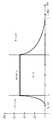
청각의 또 다른 중요한 특성은 동일한 음향 압력 레벨의 음향들의 라우드니스(loudness)의 주파수 의존적 감정이다. 청각의 두 가지 특징이 이로부터 야기한다. 한편으로, 서로 다른 주파수들이나 동일한 압력 레벨의 음향들은 서로 다른 라우드니스로서 지각되고, 다른 한편으로 음향들이 여전히 지각될 수 있는 영역으로부터 시작하는 주파수 의존적 한계가 존재한다(Fastl 및 Zwicker, 2007). 이러한 한계는 또한 절대 청각 한계 또는 조용한 상태의 청각 한계로서 언급되며 도 22에 도시된다. 이로부터 오디오 인코딩을 위한 두 가지 결론이 도출될 수 있다. 레벨들이 절대 청각 한계 아래에 존재하는 신호들은 처리될 필요가 없는데 그 이유는 신호들이 어쨌든 지각될 수 없기 때문이다. 이와 별도로, 주파수 대역 당 필요한 양자화 단계들의 수는 또한 조용한 상태의 청각 한계 및 신호 레벨 사이의 거리로부터 결정될 수 있다(Zolzer, 2005).Another important property of hearing is the frequency-dependent feelings of the loudness of the sounds at the same acoustic pressure level. Two features of hearing result from this. On the one hand, there are frequency-dependent limitations in which sounds at different frequencies or at the same pressure level are perceived as different loudness, and on the other hand, sound is still perceptible (Fastl and Zwicker, 2007). This limit is also referred to as the absolute hearing limit or the audible limit in a quiet state and is shown in Fig. From this, two conclusions can be drawn for audio encoding. Signals whose levels are below the absolute auditory limit need not be processed because the signals can not be perceived anyway. Alternatively, the number of quantization steps required per frequency band can also be determined from the distance between the audible limit and the signal level in a quiet state (Zolzer, 2005).
피복 또는 마스킹(masking) 효과들이 오디오 인코딩에 가장 큰 영향을 갖는다. 시간 및 주파수 의존적 마스킹이 차별화될 수 있다. 두 경우에 있어서, 여기서 마스커(masker)는 또 다른 음향 이벤트가 덮여있는(포함되는) 음향 이벤트로서 언급된다. 따라서, 마스킹된 이벤트는 들리지 않는다. 시간적 마스킹과 함께, 마스커 앞 또는 뒤의 이벤트가 커버된다. 예비-마스킹(pre-masking)은 마스커의 기간과 관계없고 마스커 자제를 지각하기 전에 50 ms까지 음향 이벤트들을 덮는다(Yost, 1994). 이와 대조적으로, 후-마스킹은 마스커의 기간에 의존한다. 여기서 음향 이벤트들은 마스커가 중단된 후에 덮인다. 마스커의 기간에 의존하여, 조용한 상태의 청각 한계의 범위 내에 청각이 다시 신호들에 응답할 때까지 200 ms가지 통과할 수 있다(fastl 및 Zwicker, 2007).Cladding or masking effects have the greatest impact on audio encoding. Time and frequency dependent masking can be differentiated. In both cases, the masker is referred to as an acoustic event in which another acoustic event is covered (included). Therefore, the masked event is not heard. Along with temporal masking, events before or after the masker are covered. Pre-masking covers acoustic events up to 50 ms before perceiving masquerade regardless of the duration of the masker (Yost, 1994). In contrast, post-masking depends on the duration of the masker. Here, the acoustic events are covered after the masker is stopped. Depending on the duration of the masker, it may pass 200 ms until the auditory response again responds to the signals within the audible limit of the quiet state (fastl and Zwicker, 2007).
도 21은 시간적 마스킹을 개략적으로 도시한다. 특히, 도 21은 예비-마스킹과 후-마스킹의 영역 및 아래에 신호들이 커버되는 각각의 레벨을 개략적으로 도시한다. 시간적 마스킹은 고-레벨 신호 시퀀스들(트랜지언트들)에 대하여, 예를 들면 양자화 잡음과 같은, 인코딩 과정에 의해 야기되는 스퓨리어스 잡음(spurious noise)을 감추기 위하여 오디오 인코딩에서 사용될 수 있다.Figure 21 schematically shows temporal masking. In particular, FIG. 21 schematically shows each level at which signals are covered in the areas of pre-masking and post-masking and below. Temporal masking can be used in high-level signal sequences (transients) in audio encoding to conceal the spurious noise caused by the encoding process, such as, for example, quantization noise.
주파수 도메인 내의 마스킹 효과들은 시간적 피복 효과들보다 훨씬 더 중요한 역할을 한다. 주파수-의존적 마스킹은 개별 음향들과 협대역 잡음을 위한 조용한 상태의 청각 한계의 변화를 설명한다. 이러한 신호들은 청각의 특정 마스킹된 한계에 기인하여 조용한 상태의 청각 한계를 상당히 왜곡한다. 레벨이 마스커의 마스킹된 청각 한계보다 작고 상기 한계의 효율적인 범위 내에 위치되는 신호들은 지각될 수 없다(Fastl 및 Zwicker, 2007). 이러한 문맥이 도 22에 도시된다.Masking effects in the frequency domain play a much more important role than temporal coating effects. Frequency-dependent masking accounts for changes in the auditory limit in quiet states for individual sounds and for narrow-band noise. These signals significantly distort the auditory limit of the quiet state due to the specific masked limits of hearing. Signals whose levels are less than the masked audible limit of the masker and are located within the effective range of the limit can not be perceived (Fastl and Zwicker, 2007). This context is shown in Fig.
도 22는 인간 청각 내의 주파수 의존적 마스킹을 개략적으로 도시한다. 보이는 것과 같이, 마스킹된 음향은 마스커의 마스킹된 청각의 한계 아래에 존재하고 따라서, 들리지 않는다. 이러한 효과는 손실 오디오 인코딩 방법들에서 사용된다. 주파수 의존적 마스킹된 청각의 한계 아래의 신호 부분들은 신호로부터 제거되고 더 이상 처리되지 않는다(Zolzer, 2005).Figure 22 schematically shows frequency dependent masking in the human auditory system. As can be seen, the masked sound is below the masked auditory limit of the masker and thus is inaudible. This effect is used in lossy audio encoding methods. The signal portions below the limits of the frequency-dependent masked hearing are removed from the signal and are no longer processed (Zolzer, 2005).
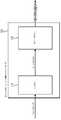
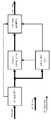
지각에 적용되는 전형적인 인코더의 일반적인 설정이 도 23에 도시된다. 도 23은 음향심리학적 오디오 인코더의 블록 회로 다이어그램을 도시한다. 처음에, 인코딩되려는 펄스 코드 변조(PCM) 신호는 분석 필터 뱅크에 의해 주파수 대역들로 분해되고 음향심리학적 모델에 제공된다. 여기서, 서로 다른 주파수 대역들을 위하여 양자화의 정확성을 조절하는 시간 의존적 마스킹된 청각의 한계가 설명된 청각의 음향심리학적 특징들에 의해 결정된다. 따라서, 중요한 주파수 대역, 즉 지각하기에 쉬운 주파수 대역들이 매우 높은 해상도로 양자화되고 중요하지 않은 주파수 대역들은 적은 수의 비트들의 해상도에서 표현된다. 그 뒤에, 또한 무손실 오디오 인코딩에서 수행되는 것과 같이, 데이터 감소를 위하여 엔트로피 인코딩이 실행된다. 부가적인 제어 파라미터들이 분석 필터 뱅크 및 음향심리학적 모델에 의해 전송되어야만 하기 때문에, 실제 비트 스트림은 비트 스트림 멀티플렉서(multiplexer)에 의해 설정된다. 손실 오디오 인코더들 내의 인코딩에서의 이득은 여기서는 양자화와 엔트로피 인코딩을 결합함으로써 획득된다(Zolzer, 2005). 달성되려는 품질에 따라, 압축 비율은 4:1 및 50:1 사이이다(Weinzierl, 2008).A typical setting of a typical encoder applied to the perception is shown in Fig. Figure 23 shows a block circuit diagram of a psychoacoustic audio encoder. Initially, the pulse code modulation (PCM) signal to be encoded is decomposed into frequency bands by the analysis filter bank and provided to the acoustic psychological model. Here, the limits of time-dependent masked hearing, which regulates the accuracy of the quantization for different frequency bands, are determined by the psychoacoustic characteristics of the auditory hearing. Thus, important frequency bands, i.e., frequency bands that are susceptible to perception, are quantized with very high resolution and unimportant frequency bands are represented with a small number of bits of resolution. Thereafter, entropy encoding is performed for data reduction, as is also done in lossless audio encoding. Since additional control parameters must be transmitted by the analysis filter bank and the psychoacoustic model, the actual bitstream is set by the bitstream multiplexer. The gain in encoding in lossy audio encoders is obtained here by combining quantization and entropy encoding (Zolzer, 2005). Depending on the quality to be achieved, the compression ratio is between 4: 1 and 50: 1 (Weinzierl, 2008).
디코더는 상대적으로 간단한 설정이다. 처음에, 수신된 비트 스트림은 디멀티플렉서에 의해 다시 신호 데이터와 제어 파라미터들로 세분된다. 그 후에, 엔트로피 디코딩과 역 양자화가 실행된다. 제어 파라미터들은 여기서 유용한 데이터의 역 양자화를 제어한다. 이러한 방법으로 획득된 부대역 신호들은 그리고 나서 광대역 펄스 코드 변조 신호를 재구성하기 위하여 합성 필터 뱅크로 제공된다(Zolzer, 2005). 음향심리학적 오디오 디코더의 각각의 블록 회로 다이어그램이 도 24에 도시된다.Decoders are relatively simple settings. Initially, the received bit stream is subdivided again into signal data and control parameters by the demultiplexer. Thereafter, entropy decoding and inverse quantization are performed. The control parameters control the dequantization of the useful data here. Subband signals obtained in this way are then provided as a synthesis filter bank to reconstruct the wideband pulse code modulated signal (Zolzer, 2005). Each block circuit diagram of a psychoacoustic audio decoder is shown in Fig.
다수의 종래 신호 변환들이 아래에 설명될 것이다. 많은 오디오 인코더들에서의 양자화가 주파수 도메인 내의 인간들의 지각을 설명하는 지각 모델을 기초로 하기 때문에, 인코딩되려는 신호를 주파수 도메인으로 전달하는 것이 또한 필요하다. 이를 위하여 서로 다른 특징들을 갖는 다수의 변환과 적용 분야들이 존재한다. 오디오 인코딩에 적절한 변환들이 아래에 표시될 것이며 필터 뱅크의 설정이 논의될 것이다.A number of conventional signal transformations will be described below. Since the quantization in many audio encoders is based on a perceptual model that describes the perception of humans in the frequency domain, it is also necessary to pass the signal to be encoded to the frequency domain. To this end, there are a number of transformations and applications with different features. Transformations appropriate for audio encoding will be displayed below and the setting of the filter bank will be discussed.
푸리에 변환은 신호의 고조파 구조(harmonic structure)를 분석하기 위한 가장 중요한 방법이다. 이는 푸리에 분석의 일부이고 이를 처음으로 도입한 프랑스 수학자이자 물리학자인 Jean-Baptiste-Joseph Fourier(1768-1830) 이후에 명명되었다. 푸리에 변환은 시간 신호를 주파수 도메인 내의 그것의 표현에 전달하기 위한 함수이다. 무엇보다도, 이는 선형 시불변(linear temporarily invariant, LTI) 시스템들의 실행을 설명하고 이를 예측할 수 있도록 하기 위하여 사용된다(Burrus 및 Parks, 1985). 따라서, 이는 예를 들면 음향학 및 인간 청각의 특징들에서 매우 중요하다. 푸리에 변환의 기본 과정은 시간 신호의 사인과 코사인 진동의 가중 합계로의 분해이다. 비주기적 연속 신호들을 위하여, 이는 다음과 같이 계산된다(Bosi 및 Goldberg, 2003):Fourier transform is the most important method for analyzing the harmonic structure of a signal. It was named after Jean-Baptiste-Joseph Fourier (1768-1830), a French mathematician and physicist who was part of the Fourier analysis and introduced it for the first time. The Fourier transform is a function for transferring a time signal to its representation in the frequency domain. Above all, it is used to describe and predict the performance of linear temporal invariant (LTI) systems (Burrus and Parks, 1985). Thus, it is very important, for example, in terms of acoustics and human hearing. The basic process of Fourier transform is the decomposition into the sum of the sine of the time signal and the weighted sum of the cosine oscillations. For aperiodic continuous signals, this is calculated as follows (Bosi and Goldberg, 2003):

여기서, x(t)는 시간 도메인 내의 분석되려는 신호이고 X(f)는 주파수 도메인 내의 각각의 푸리에 스펙트럼이다. 비록 실제 신호가 변환되지만 결과는 복잡하다는 것에 유의하여야 한다. 방정식 2.2에서 오일러 관계식(Eulerean relation)을 사용하여, X(f)의 실수 부분은 x(t)의 코사인 항들과 상응하고 허수 부분은 사인 성분들과 상응한다는 것을 나타낼 수 있다. 다음의 방정식을 사용하여:Where x (t) is the signal to be analyzed in the time domain and X (f) is the respective Fourier spectrum in the frequency domain. It should be noted that although the actual signal is converted, the result is complex. Using the Eulerean relation in Eq. 2.2, the real part of X (f) corresponds to the cosine terms of x (t) and the imaginary part corresponds to the sine components. Use the following equation:
e-j2πft = cos(2πft) - jsin(2πft)(2.2)e-j2?ft = cos (2?ft ) - jsin (2?ft ) (2.2)
방정식 2.1의 결과는 다음과 같으며:The results of equation 2.1 are as follows:


다음을 야기한다:It causes the following:
X(f) = Re{X(f)} + jIm{X(f)}(2.5)X (f) = Re {X (f)} + jIm {X (f)} (2.5)
사인과 코사인은 그것들의 위상에서만 서로 다르기 대문에, 신호의 위상은 상응하는 항들의 비율로부터 완결될 수 있다. 다음이 적용된다:Since sine and cosine differ only in their phase, the phase of the signal can be completed from the ratio of the corresponding terms. The following applies:

및:And:


따라서, |X(f)|는 절대 값 주파수 응답으로서 언급되고 Φ(f)는 위상 주파수 응답 또는 간단하게 위상으로서 언급된다.Thus, | X (f) | is referred to as an absolute value frequency response and? (F) is referred to as a phase frequency response or simply as a phase.
역 푸리에 변환(방정식 2.9)에 기인하여, 변환된 신호는 다시 시간 도메인 내의 그것의 원래 표현에 전달된다. 푸리에 변환과 그것의 역은 상수 인자 및 지수 함수의 부호가 다르다(Burrus 및 Parks, 1985).Due to the inverse Fourier transform (Equation 2.9), the transformed signal is again passed to its original representation in the time domain. The Fourier transform and its inverse differ in the signs of the constant and exponential functions (Burrus and Parks, 1985).

이산 푸리에 변환이 아래에 더 상세히 설명될 것이다.The discrete Fourier transform will be described in more detail below.
실제로, 푸리에 변환을 사용할 때 디지털 컴퓨터들에서 문제점들이 발생한다. 한편으로, 이는 시간 값들의 무한 수만이 처리될 수 있다는 사실에 기인하고, 다른 한편으로, 주파수 변수가 또한 시간 변수를 제외하고 분리되어 샘플링되어야만 한다. 이러한 문제점들의 해결책이 이산 푸리에 변환(DFT)이다. 이산 푸리에 변환을 사용하여, 유한의, 이산-시간 신호가 이산의, 주기적 스펙트럼에 전달된다. 이는 이산 푸리에 변환이 디지털 신호 처리에서 가장 중요한 변환 중의 하나라는 것을 의미한다. 이산 푸리에 변환의 기원은 푸리에 변환에서 발견되며, 정확한 편차가 발견될 수 있다(Lochmann, 1990). 길이(N)의 이산-시간 신호(x[n])의 이산 푸리에 변환은 다음과 같이 정의된다(Burrus 및 Parks, 1985):In practice, problems arise in digital computers when using Fourier transforms. On the other hand, this is due to the fact that only infinite number of time values can be processed, and on the other hand, the frequency variable must also be sampled separately except for the time variable. The solution to these problems is discrete Fourier transform (DFT). Using a discrete Fourier transform, a finite, discrete-time signal is passed to the discrete, periodic spectrum. This means that discrete Fourier transform is one of the most important transformations in digital signal processing. The origin of the discrete Fourier transform is found in the Fourier transform, and accurate deviations can be found (Lochmann, 1990). The discrete Fourier transform of the discrete-time signal of length N (x [n]) is defined as follows (Burrus and Parks, 1985):

유사하게, 역 이산 푸리에 변환(IDFT)은 다음과 같으며:Similarly, the inverse discrete Fourier transform (IDFT) is as follows:

복소 회전 페이저(complex rotating phasor, W)는 다음과 같다:The complex rotating phasor (W) is:

따라서, X[k]는 ∀k,n ∈ N을 갖는 x[n]의 이산의 주기적 스펙트럼이다. 스펙트럼의 주기 길이는 변환 길이(N)와 상응하고 정규화 주파수들은 간격([0,2π]) 내에 매핑된다.Thus, X [k] is the periodic spectrum of discrete x [n] with ∀k, n ∈ N. The period length of the spectrum corresponds to the transform length (N) and the normalized frequencies are mapped in the interval ([0, 2π]).
실제 입력 신호들을 위하여, 이산 푸리에 변환은 중요한 특징을 갖는다. 여기서, N 독립적 주파수 계수들은 일반적인 경우에서 흔히 있는 경우지만 여기서는 계산되지 않고 그것의 반만이 계산된다. 이러한 특징은 바람직하게는 데이터의 저장 및 전송을 위하여 사용될 수 있다. 재변환을 위하여, 다음의 상관관계를 사용하여 제2(N/2) 값들이 계산된다(Rao 및 Yip, 2001):For real input signals, the discrete Fourier transform has important features. Here, N independent frequency coefficients are common in the general case, but not calculated here but only half of them. This feature is preferably used for storage and transmission of data. For re-conversion, the second (N / 2) values are calculated using the following correlation (Rao and Yip, 2001):
X[N - k} = X[k]* (2.13)X [N - k] = X [k]* (2.13)
방정식 2.13에서의 연산자(*)는 복소 공액(complex conjugate)을 특징으로 한다. 따라서, X[k]*는 X[k]를 위한 값들의 복소 공액 시퀀스이다.The operator (*) in equation 2.13 is characterized by a complex conjugate. Thus, X [k] * is a complex conjugate sequence of values for X [k].
이산 푸리에 변환과 역 이산 푸리에 변환의 계산 복잡도는 N2 복소수 곱셈들과 덧셈들이다. 계산할 때 대칭들이 사용될 때, 필요한 계산 단계들의 수는 N|dN으로 감소되고 복잡도는
이산 푸리에 변환은 데이터 압축의 분야에서 회복된 수용을 갖지 않는다. 이산 푸리에 변환은 상당한 단점은 높은 계산 복잡도 및 스펙트럼 내에 포함된 중복이다. 비록 이산 푸리에 변환을 위하여 효율적인 방법들, 즉 고속 푸리에 변환이 존재하나, 결과는 항상 복합 스펙트럼일 것이다. 이는 값들의 N 복소수 쌍들이 N 변환 값들로부터 계산된다는 것을 의미한다. 게다가, 제 1 N/2 스펙트럼 값들만이 새로운 정보를 포함한다.Discrete Fourier transforms do not have recovered acceptance in the field of data compression. A disadvantage of discrete Fourier transforms is the high computational complexity and redundancy contained within the spectrum. Although there are efficient methods for discrete Fourier transforms, i.e. fast Fourier transforms, the result will always be a complex spectrum. This means that N complex number pairs of values are calculated from the N transform values. In addition, only the first N / 2 spectral values contain new information.
이산 코사인 및 사인 변환들이 아래에 설명될 것이다.Discrete cosine and sine transformations will be described below.
이산 코사인 변환(DCT)은 앞서 언급된 이산 푸리에 변환의 문제점들의 해결책이다. 이산 코사인 변환은 실제, 이산, 선형 및 직교 변환(orthogonal transform)이다. 이러한 특징들 때문에, 이는 디지털 데이터 압축에서 가장 빈번하게 사용된다(Britanak 등, 2007).The discrete cosine transform (DCT) is a solution to the problems of the discrete Fourier transform discussed above. Discrete cosine transforms are real, discrete, linear, and orthogonal transforms. Because of these features, this is most frequently used in digital data compression (Britanak et al., 2007).
이산 코사인 변환은 이산 삼각(trigonometric) 변환이다. 대체로, 8가지 이산 코사인 형태가 그것들 사이에 차별화된다. 그것들의 에지 연속(edge continuation)에 따라, 그것들은 짝수 및 홀수 변환들 및 형태들 Ⅰ, Ⅱ, Ⅲ, Ⅳ로 세분된다. 그러나, 디지털 신호 처리를 위하여, 짝수 형태의 이산 코사인 변환만이 중요하다. 이들에 아래에 열거된다(Rao 및 Yip, 2001):The discrete cosine transform is a discrete trigonometric transform. In general, eight discrete cosine types are differentiated between them. Depending on their edge continuation, they are subdivided into even and odd transformations and types I, II, III, and IV. However, for digital signal processing, only an even-numbered discrete cosine transform is important. These are listed below (Rao and Yip, 2001):


여기서:here:

이러한 형태들 각각은 인코딩에서 그것의 특정 적용을 갖는다. 이산 코사인 변환-Ⅱ는 주로 이미지 데이터의 변환으로서 사용된다. 문헌은 이를 설명되는 이산 변환의 첫 번째 형태로서 간주한다. 이는 일반적으로 용어 "이산 코사인 변환"이 이산 코사인 변환-Ⅱ를 언급한다는 것을 의미한다(Ahmed 등, 1974). 전인자(pre-factor)를 제외하고, 이산 코사인 변환-Ⅲ은 이산 코사인 변환-Ⅱ의 역 변환이고 반대도 마찬가지이다. 오디오 인코딩을 위하여, 이산 코사인 변환-Ⅳ가 특히 중요하다. 이는 변형된 이산 코사인 변환의 기준이다.Each of these forms has its particular application in the encoding. The discrete cosine transform-II is mainly used as a transform of image data. The literature considers this as the first form of discrete transformation to be explained. This generally means that the term " discrete cosine transform "refers to discrete cosine transform-II (Ahmed et al., 1974). Except for the pre-factor, discrete cosine transform-III is the inverse of discrete cosine transform-II and vice versa. For audio encoding, discrete cosine transform-IV is particularly important. This is the basis of the transformed discrete cosine transform.
이산 코사인 변환의 중요한 특징들을 설명할 수 있도록 하기 위하여, 이산 푸리에 변환과 이산 코사인 변환 사이의 상관관계가 아래에 설명될 것이다. 앞에 도시된 것과 같이, 이산 푸리에 변환은 길이(N)의 실제 값 신호로부터 N/2 독립적 주파수 계수들만을 계산한다. 반대로, 이는 N 스펙트럼 값들을 획득하기 위하여 시간 도메인 내의 N/2 값들이 필요하다는 것을 의미한다. 그러나, 만일 N 시간 값들이 이용가능하면, 신호는 적절하게 계속되어야만 한다. 전체 신호의 반사/미러링(mirroring)에 의한 대칭적 확장이 여기서 적절한 것으로 여겨진다. 확장된 신호는 따라서 2N의 기간 길이에서 자체로 반복하는 것으로 여겨진다. 이는 단축 신호를 갖는 이산 푸리에 변환의 스퓨리어스 누설 효과(spurious leakage effect)가 억제된다는 점에서 바람직하다(Kiencke 및 Jakel, 2005).In order to be able to explain the important features of the discrete cosine transform, the correlation between the discrete cosine transform and the discrete cosine transform will be described below. As shown before, the discrete Fourier transform computes only N / 2 independent frequency coefficients from the actual value signal of length (N). Conversely, this means that N / 2 values in the time domain are needed to obtain N spectral values. However, if N time values are available, the signal must continue properly. A symmetric extension by reflection / mirroring of the entire signal is considered to be appropriate here. The extended signal is thus considered to repeat itself in a period length of 2N. This is desirable in that the spurious leakage effect of the discrete Fourier transform with the unicast signal is suppressed (Kiencke and Jakel, 2005).
길이(N)의 어떠한 실제 값(x[n])이 대칭적으로 확장하고, 결과는 다음과 같으며:Any actual value (x [n]) of length (N) extends symmetrically and the result is as follows:

여기서 0≤n≤2N-1이다. 12의 길이는 따라서 2N이다. 방정식 2.12와 함께 2.10으로부터의 이산 푸리에 변환은 그리고 나서 이러한 신호에 적용되고 전환된다(Rao 및 Yip, 2001). 상세한 편차가 별첨 1.1에서 발견된다. 다음이 적용된다:Where 0? N? 2N-1. The length of 12 is therefore 2N. The discrete Fourier transform from 2.10 with equation 2.12 is then applied to these signals and is transformed (Rao and Yip, 2001). Detailed deviations are found in Appendix 1.1. The following applies:


이러한 결과를 방정식 2.14b에서의 이산 코사인 변환-Ⅱ와 비교할 때, 이러한 두 가지 방정식은 단지 위상 항(
일부 결론들이 이러한 결과로부터 도출될 수 있다. 처음에, 이산 코사인 변환은 이산 푸리에 변환과 비교하여, 순수한 실제 변환인 것을 알 것이다. 이로부터 두 가지 장점을 야기한다. 첫 번째로, 계산을 위하여 어떠한 복소수 곱셈과 덧셈도 실행될 필요가 없으며, 두 번째로, 데이터를 저장하기 위하여 저장 공간의 단지 반만이 필요한데 그 이유는 값들의 어떠한 복소수 쌍들도 존재하지 않기 때문이다. 게다가, N 독립 주파수 계수들을 계산하기 위하여 이산 코사인 변환이 변환을 위하여 정확하게 N 값들을 필요로 한다는 것이 매력적이다. 주파수들을 모두 간격([0, π]) 내에 존재한다. 이산 푸리에 변환과 대조적으로, 실제 값 입력 신호들을 위한 스펙트럼 내에 포함된 중복은 사라졌고 따라서 주파수 해상도는 두 배만큼 높다. 그러나, 이산 코사인 변환 스펙트럼이 절대 값(또는 크기) 및 위상에 대하여 변환될 수 없는 것이 단점이다. 부가적으로, 이산 코사인 변환 기초 함수(예를 들면, 방정식 2.14a 내지 2.14d)와 대응하지만 거기에 대하여 위상이 90도 만큼 회전되는 주파수들이 신호 내에 포함되는 상황이 일어날 수 있다. 이러한 주파수들은 이산 코사인 변환에 의해 표현되지 않는데, 즉 각각의 이산 코사인 변환 계수는 제로이다. 이러한 이유들 때문에, 이산 코사인 변환은 효율적이고 고속 데이터 압축을 위하여 상당히 적합하나, 신호 분석을 위해서는 덜 적합하다(Malvar, 1992).Some conclusions can be drawn from these results. First, you will see that the discrete cosine transform is a pure real transform, as compared to the discrete Fourier transform. This leads to two advantages. First, no complex multiplication and addition need to be performed for computation, and second, only half of the storage space is required to store the data, since no complex number pairs of values exist. In addition, it is attractive that the discrete cosine transform requires precisely N values for the transform to compute N independent frequency coefficients. All frequencies are within the interval ([0, π]). In contrast to the discrete Fourier transform, the redundancy contained within the spectrum for the actual value input signals has disappeared and therefore the frequency resolution is twice as high. However, the disadvantage is that the discrete cosine transform spectrum can not be transformed with respect to the absolute value (or magnitude) and phase. Additionally, a situation may occur in which the frequency corresponds to a discrete cosine transform based function (e.g., equations 2.14a through 2.14d) but to which the phase is rotated by 90 degrees. These frequencies are not represented by discrete cosine transforms, that is, each discrete cosine transform coefficient is zero. For these reasons, discrete cosine transforms are well suited for efficient and high-speed data compression, but are less suitable for signal analysis (Malvar, 1992).
이산 코사인 변환 이외에, 이산 사인 변환(DST)이 존재한다. 대체로, 그것들 사이에 8가지 형태의 이산 사인 변환이 구별된다. 여기서는 이산 사인 변환-Ⅳ만이 중요하다. 그것의 형태와 특징들과 관련하여, 이는 이산 코사인 변환-Ⅳ와 상응한다(Rao 및 Yip, 2001).In addition to the discrete cosine transform, there is a discrete cosine transform (DST). In general, there are eight types of discrete sine transforms between them. Here, only discrete sine transform-IV is important. Regarding its form and characteristics, it corresponds to the discrete cosine transform-IV (Rao and Yip, 2001).

이산 코사인 변환-Ⅳ과 이산 사인 변환-Ⅳ 모두를 사용하여 신호가 변환될 때, 두 개의 실제 스펙트럼의 조합에 의해 형성되는 복합 스펙트럼은 다시 절대 값과 위상에 대한 정보를 포함한다. 여기서 주파수 해상도는 여전히 이산 푸리에 변환에서보다 두 배만큼 높은데, 이는 N 주파수들이 간격([0, π]) 내에 매핑되는 것을 의미한다(Malvar, 1992).When the signal is transformed using both discrete cosine transform-IV and discrete sinusoidal transform-IV, the composite spectrum formed by the combination of the two actual spectra again contains information on the absolute value and the phase. Where the frequency resolution is still twice as high as in the discrete Fourier transform, which means that N frequencies are mapped in the interval ([0, π]) (Malvar, 1992).
긴 오디오 신호들의 신호 처리를 위하여, 전체로서 신호를 변환하는 것은 가능하지 않다. 한편으로, 여기서 계산 복잡도는 엄청나게 증가하는데 그 이유는 또한 이산 코사인 변환을 계산하기 위하여 N2 계산 연산들이 필요하기 때문이다. 다른 한편으로, 실시간으로 신호를 처리하는 것이 가능하지 않은데 그 이유는 전체 데이터 스트림의 전송은 신호가 재구성될 수 있을 때까지 항상 기다려야만 하기 때문이다. 결론적으로, 신호가 블록들로 세분되는 것이 필요하다. 이 경우에 있어서, 이산 코사인 변환은 이른바 블록 변환으로서 적용된다(Rao 및 Yip, 2001). 블록 지수(b∈N)를 사용하여, 방정식 2.14로부터의 이산 코사인 변환-Ⅳ를 위하여 다음이발생한다:For signal processing of long audio signals, it is not possible to convert the signal as a whole. On the one hand, the computational complexity here increases tremendously because N2 computation operations are also required to compute the discrete cosine transform. On the other hand, it is not possible to process the signal in real time because the transmission of the entire data stream must always wait until the signal can be reconstructed. In conclusion, it is necessary that the signal is subdivided into blocks. In this case, the discrete cosine transform is applied as a so-called block transform (Rao and Yip, 2001). Using the block index (b∈N), for discrete cosine transform-IV from Eq. 2.14, the following occurs:

(2.19)(2.19)
x[n]의 신호 길이는 bN과 상응한다. 블록 변환으로, 양자화에 의해 블록 아티팩트(block artefact)들이 발생한다. 이러한 형태의 아티팩트들이 인식될 수 있는 알려진 예가 JPEG 압축 방법이다. 블록 아티팩트들은 주기화(periodizing)를 위하여 실행되려는 에지 연장선들로부터 기원한다. 그것들은 원래 추정된 신호 연속성들과 상응하지 않는다(예를 들면, 방정식 2.16). 결과들은 주파수 도메인 내에서 고주파수를 향하여 에너지를 이동시키는 블록 한계들 내의 점프(jump)들이다(Malvar, 1992). 오디오 신호 내의 점프들은 크래클(crackle)들로서 지각될 수 있다. 인간 청각은 그러한 아티팩트들에 매우 민감하다. 따라서, 그것들은 절대적으로 방지되어야만 한다.The signal length of x [n] corresponds to bN. With block transformations, block artefacts are generated by quantization. A known example of how these types of artifacts can be recognized is the JPEG compression method. The block artifacts originate from edge extension lines that are to be executed for periodizing. They do not correspond to the originally estimated signal continuations (eq. 2.16, for example). The results are jumps within the block limits that shift energy towards higher frequencies in the frequency domain (Malvar, 1992). The jumps in the audio signal can be perceived as crackles. Human hearing is very sensitive to such artifacts. Therefore, they must be absolutely prevented.
변형 이산 코사인 변환이 아래에 설명될 것이다.The transformed discrete cosine transform will be described below.
변형 이산 코사인 변환(MDCT)은 오디오 압축을 위한 중심 변환이다. 그 중에서도, 이는 mp3, 고급 오디오 코딩(AAC) 및 돌비 디지털(Dolby Digital, ac-3)에서 사용된다. 변형 이산 코사인 변환은 실제, 이산 선형 및 직교 변환이고 이산 코사인 변환-Ⅳ의 변형이다. 이는 다음과 같이 정의된다(Rao 및 Yip, 2001):Modified Discrete Cosine Transform (MDCT) is the center transform for audio compression. Among them, it is used in mp3, advanced audio coding (AAC) and Dolby Digital (ac-3). The modified discrete cosine transform is actually a discrete linear and orthogonal transform and is a modification of the discrete cosine transform-IV. This is defined as follows (Rao and Yip, 2001):

(2.20)(2.20)
이산 코사인 변환-Ⅳ와 비교하여 변형 이산 코사인 변환의 장점은 블록 아티팩트들의 방지이다. 이는 주로 일부 연속적인 블록들의 오버래핑에 의해 달성될 수 있다. 이러한 형태의 변환은 또한 겹침 직교 변환(lapped orthogonal transform, LOT)로 알려져 있다(Malvar 및 Staelin, 1989).The advantage of transformed discrete cosine transforms compared to discrete cosine transforms-IV is the prevention of block artifacts. This can be achieved primarily by overlapping some successive blocks. This type of transformation is also known as lapped orthogonal transform (LOT) (Malvar and Staelin, 1989).
중복은 중첩-가산(overlap-add, OLA) 방법에 의해 다시 제거될 수 있다. 따라서, 역 변환 내에서 형성하는 블록들은 50%까지 중첩되고 가산되며, 이러한 과정은 중첩-가산으로서 언급된다.The redundancy can be removed again by an overlap-add (OLA) method. Thus, the blocks that form within the inverse transform are superimposed and summed up to 50%, and this process is referred to as overlap-addition.
변형 이산 코사인 변환의 주파수 해상도는 윈도우 함수와 함께 입력 시퀀스(x[n+bN])을 가중함으로써 더 향상될 수 있다. 방정식 2.20에서, 윈도우는 전체 신호로부터 현재 블록(b)을 클리핑하는(clipping) 직사각형 함수와 상응한다. 주파수 도메인에서, 이는 si 함수를 사용하는 콘볼루션(convolution, 폴딩)과 상응한다. si 함수의 빈약한 저지 대역 감쇠는 이러한 윈도우 함수를 적용함으로써 향상될 수 있고 따라서 증가된 주파수 선택성이 달성될 수 있다. 변형 이산 코사인 변환이 완벽하게 재구성될 수 있도록 하기 위하여, 길이(2N)의 윈도우 함수(w[n])는 프린슨-브래들리(Pricen-Bradley condition)들을 만족시켜야만 한다(Princen 등, 1987):The frequency resolution of the transformed discrete cosine transform can be further improved by weighting the input sequence (x [n + bN]) with the window function. In equation 2.20, the window corresponds to a rectangular function that clips the current block b from the overall signal. In the frequency domain, this corresponds to a convolution using the si function. The poor low band attenuation of the si function can be improved by applying this window function and thus increased frequency selectivity can be achieved. In order to allow the transformed discrete cosine transform to be completely reconstructed, the window function w [n] of
w[n] = w[2N-1-n] (2.21a)w [n] = w [2N-1-n] (2.21a)
w2[n] = w2[n+N] = 1 (2.21b)w2 [n] = w2 [n + N] = 1 (2.21b)
이러한 조건들을 만족시키고 충분한 저지 대역 감쇠를 나타내는 간단한 윈도우는 사인 반파장 윈도우(sine half wave window)이다. 이는 그중에서도, mp3 및 고급 오디오 코딩에서 사용되고 다음과 같이 정의된다(Malvar, 1992):A simple window that satisfies these conditions and exhibits sufficient stopband attenuation is a sine half wave window. Among them, it is used in mp3 and advanced audio coding and is defined as follows (Malvar, 1992):

윈도우 함수(w[2N-1-n])를 방정식 2.20에 삽입함으로써, 변형 이산 코사인 변환의 또 다른 중요한 특징이 인식될 수 있다. 결과는 변조된 윈도우 함수(w[n])를 사용하는 x[n+bN]의 이산 콘볼루션과 상응한다. 따라서, ∀k∈[0,N-1]을 위하여, 다음이 발생한다(Schuller 및 Smith, 1996):By inserting the window function w [2N-1-n] into equation 2.20, another important feature of transformed discrete cosine transform can be recognized. The result corresponds to a discrete convolution of x [n + bN] using the modulated window function (w [n]). Thus, for ∀k∈ [0, N-1], the following occurs (Schuller and Smith, 1996):

(2.23)(2.23)
따라서, 변형 이산 코사인 변환은 블록 변환으로 보일 수 없을 뿐만 아니라 변조된 필터 뱅크로도 보일 수 없다(Malvar, 1992). 따라서, 윈도우 함수는 코사인 커널(cosine kernel)에 의해 변조되고 따라서 필터 뱅크의 주파수 대역들을 표현하는 로-패스(low-pass) 프로토타입 유한 임펄스 응답(FIR) 필터와 상응한다. 이의 결과는 입력 시퀀스(x[n+bN])가 정확하게 N 부대역들로 분해되는 것이다. 시간 도메인 에일리어싱(TDA) 특징과 관련하여, 변형 이산 코사인 변환은 이른바 "임계적으로 샘플링된 필터 뱅크"의 전제조건들을 충족시킨다.Thus, the modified discrete cosine transform can not be seen as a block transform, nor can it be seen as a modulated filter bank (Malvar, 1992). Thus, the window function corresponds to a low-pass prototype finite impulse response (FIR) filter that is modulated by a cosine kernel and thus represents the frequency bands of the filter bank. The result is that the input sequence (x [n + bN]) is correctly decomposed into N subbands. Regarding the time domain aliasing (TDA) feature, the modified discrete cosine transform satisfies the preconditions of the so-called "threshold sampled filter bank ".
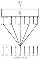
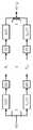
그러한 임계적으로 샘플링된 필터 뱅크가 도 25에 도시된다. 특히, 도 25는 nd 샘플들의 시스템 지연을 갖는 N-대역 임계적으로 샘플링된 완전한 재구성(PR) 필터 뱅크를 도시한다. 그러한 필터 뱅크들은 오디오 인코딩을 위하여 특히 중요한데 그 이유는 그것들이 가장 적은 수의 샘플들로 가능한 한 정확하고 완전하게 신호를 기술하기 때문이다(Rao 및 Yip, 2001).Such a critically sampled filter bank is shown in Fig. In particular, FIG. 25 shows a complete reconstruction (PR) filter bank that is N-band threshold sampled with a system delay of nd samples. Such filter banks are especially important for audio encoding because they describe the signal as accurately and completely as possible with the smallest number of samples (Rao and Yip, 2001).
기호 ↓N은 인자(1/N)에 의한 샘플 비율의 감소와 상응하고 ↑N은 인자(N)에 의한 증가와 상응한다. 합성 필터 뱅크(
수학적 관점으로부터, 벡터 매트릭스 회전에서, 지금까지 언급된 모든 변환을 포함하는 선형 방정식 시스템들을 공식화하는 것이 적합하다. 길이(bN)의 신호(x[n])는 열 벡터(column vector,

변환 규칙은 또한 매트릭스로서 표현될 수 있다. 변조된 윈도우 함수들은 여기서 매트릭스의 라인들을 형성한다. ∀k∈[0.N-1], ∀k∈[0.2N-1]을 위하여, 다음이 적용된다:The transformation rule can also be expressed as a matrix. The modulated window functions form here the lines of the matrix. For ∀k∈ [0.N-1], ∀k∈ [0.2N-1], the following applies:

(2.25)(2.25)


여기서:here:


블록을 계산하기 위하여, 변형 이산 코사인 변환의 이러한 형태는 2N2 곱셈들과 덧셈들을 필요로 한다. 그러나, 계산 복잡도는 상당히 감소될 수 있다.To compute the block, this form of transformed discrete cosine transform requires 2N2 multiplications and additions. However, the computational complexity can be significantly reduced.
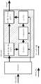
따라서, 도 25의 필터 뱅크를 등가 다위상(equivalent polyphase) 필터 뱅크로 전달하는 것이 필요하다(도 26 참조). 다위상 표현과 z-변환을 사용하여, 변형 이산 코사인 변환 같은, 멀티레이트 시스템(multirate system)들이 더 광범위하게 분석될 수 있다.Therefore, it is necessary to transfer the filter bank of Fig. 25 to an equivalent polyphase filter bank (see Fig. 26). Using multiphase representation and z-transform, multirate systems such as modified discrete cosine transforms can be analyzed more extensively.
유한 임펄스 응답 필터(h[n])는 필터의 길이가 M의 정수 배수와 상응할 때 항상 M∈N 위상들로 세분될 수 있다. h[n]의 m번째 위상(pm[n])은 z-m에 의한 지연(n[]n) 및 인자 M에 의한 샘플 레이트의 감소에 의해 생산된다(Malvar, 1992). 다음이 적용된다:The finite impulse response filter h [n] can always be subdivided into M? N phases when the length of the filter corresponds to an integer multiple of M. The mth phase (pm [n]) of h [n] is produced by the reduction of the sample rate by the factorm and the delay by n-m (n [] n) (Malvar, 1992). The following applies:
pm[n] = h[nM + m] (2.28)p m [n] = h [ nM + m] (2.28)
분해 및 z-변환을 사용하여, 필터(h[n])는 다음과 같이 표현될 수 있다(Malvar, 1992):Using decomposition and z-transform, the filter h [n] can be expressed as (Malvar, 1992):


덧셈 기호 대신에, 여기서는 또한 벡터 기호가 바람직하다. 방정식 2.30은 따라서 N차원 벡터로서 표현될 수 있다:Instead of a plus sign, here a vector sign is also preferred. Equation 2.30 can thus be expressed as an N-dimensional vector:

여기서:here:

이러한 다위상 분해는 그리고 나서 변형 이산 코사인 변환 필터 뱅크의 각각의 필터에 적용될 수 있다. 결과는 도 26의 이전에 언급된, 필터 뱅크의 등가 다위상 표현이다(Schuller 및 Smith, 1996). 따라서, 도 26은 등가 N-대역 임계적으로 샘플링된 완전 재생 다위상 필터 뱅크를 표현한다.This polyphase decomposition can then be applied to each filter of the transformed discrete cosine transform filter bank. The result is the equivalent polyphase representation of the filter bank previously mentioned in FIG. 26 (Schuller and Smith, 1996). Thus, Figure 26 represents a fully regenerated polyphase filter bank that is sampled critically with the equivalent N-band.
변형 이산 코사인 변환 및 시간 도메인 에일리어싱 특징에서의 대칭성을 사용하여, 분석 및 합성 다위상 필터 매트릭스(


폴딩 매트릭스들의 정확한 형태 및 스플리팅(splitting)은 아래에 더 나타낼 것이다. 변환 매트릭스들은 이산 코사인 변환-Ⅳ 매트릭스와 상응한다:The exact form and splitting of the folding matrices will be further illustrated below. The transform matrices correspond to discrete cosine transform-IV matrices:


이러한 매트릭스들을 사용하여, 블록들(

여기서 역 변환을 위하여 다음이 적용된다:Here for the inverse transform the following applies:

이러한 해결책은 방정식 2.26에 따른 변형 이산 코사인 변환의 계산과 비교하여 몇몇 장점을 제공한다. 첫 번째로, 시간 도메인 에일리어싱 형성이 더 쉽게 식별될 것이다. 방정식 2.33a에서의 폴딩 매트릭스의 다위상 표현으로, 과정은 블록(b-1)의 가중된 신호 부분들을 현재 블록(b)에 넘겨지는 것으로 해석될 수 있다. 이러한 신호 부분들을 더함으로써, 시간 도메인 에일리어싱이 형성된다. 다위상을 사용하여 변형 이산 코사인 변환을 계산하는 가장 큰 장점은 계산 복잡도가 상당히 감소된다는 것이다.This solution provides several advantages compared to the calculation of the modified discrete cosine transform according to equation 2.26. First, time domain aliasing formation will be more easily identified. With the multiphase representation of the folding matrix in equation 2.33a, the process can be interpreted as passing the weighted signal portions of block (b-1) to the current block (b). By adding these signal portions, time domain aliasing is formed. The main advantage of calculating a transformed discrete cosine transform using polyphase is that the computational complexity is significantly reduced.
사각형의 이산 코사인 변환-Ⅳ 매트릭스와 드물게 점유된 폴딩 매트릭스를 사용함으로써, 계산 복잡도는 N(N=2) 곱셈들 및 덧셈들로 감소된다. 고속 푸리에 변환과 유사하게, 이산 코사인 변환의 고속 구현을 사용함으로써, 필요한 연산의 수는 N(logN+2)로 감소될 수 있고 따라서 복잡도는
오디오 신호 처리에 있어서, 저주파수의 신호를 더 높은 주파수로 이동시키는 것이 필요할 수 있으며, 상기 주파수 이동은 자유롭게 선택가능하고 정확하여야만 한다. 신호의 높은 주파수들을 복원하도록 시도하는 오디오 인코더들은 이러한 문제점에 직면한다. 현대 오디오 인코딩 기술들은 오디오 데이터의 더 효율적인 압축을 위하여 대역폭 확장의 방법들을 사용한다. 인간 청각의 음향심리학적 특징들 외에, 데이터 감소를 위하여 고주파수 부분들에 대한 저주파수 부분들의 상관관계가 사용된다.In audio signal processing, it may be necessary to move the low frequency signal to a higher frequency, and the frequency shift must be freely selectable and accurate. Audio encoders that attempt to recover high frequencies of the signal encounter this problem. Modern audio encoding techniques use methods of bandwidth extension for more efficient compression of audio data. In addition to acoustic psychological features of human hearing, correlation of low frequency portions to high frequency portions is used for data reduction.
오디오 인코딩에 의해 데이터 비율을 감소시키는 다양한 방법에도 불구하고, 현재 오디오 인코더들은 낮은 비트 레이트들이 바람직할 때 그것들의 한계들에 도달한다. 특히 이 경우에 있어서 음향심리학적 방법이 사용은 바람직하지 않은 신호 변형들을 생산한다. 이는 재생된 오디오 신호의 손실 높이, 흐릿한 트랜지언트 또는 인공적 히싱(hissing) 같은, 간섭 아티팩트들에서 볼 수 있다. 그러나 많은 적용의 경우에 있어서, 제한된 전송 대역폭만이 이용가능하다. 대역폭 확장(BWE)은 이러한 문제점들을 위한 해결책을 제공한다. 일반적으로, 대역폭 확장은 원래의 대역폭을 다시 획득하기 위하여 어떠한 대역-제한된 오디오 신호가 스펙트럼으로 확장될 수 있는지를 사용하는 다수의 방법을 통합한다. 대체로, 대역폭 확장을 위하여 그것들 사이에 4가지 범주의 방법이 구별된다(Larsen 및 Aarts, 2004). 이것들이 도 27에 그래프로 도시된다.Despite the various methods of reducing the data rate by audio encoding, current audio encoders reach their limits when low bit rates are desirable. Especially in this case the use of acoustic psychological methods produces undesirable signal variations. This can be seen in the interference artifacts, such as loss height of the reproduced audio signal, blurry transient or artificial hissing. However, for many applications, only limited transmission bandwidth is available. Bandwidth extension (BWE) provides a solution for these problems. In general, bandwidth expansion incorporates a number of methods that use what band-limited audio signals can be extended to the spectrum in order to regain the original bandwidth. In general, four categories of methods are distinguished between them for bandwidth extension (Larsen and Aarts, 2004). These are shown graphically in Fig.
도 27은 대역폭 확장의 범주들을 도시한다(Larsen 및 aarts, 2004). 도 27에서, 저주파수 음향심리학적 대역폭 확장이 상단 왼쪽에 도시된다. 도 27에서, 고주파수 음향심리학적 대역폭 확장이 상단 오른쪽에 도시된다. 도 27은 하단 왼쪽에 저주파수 대역폭 확장을 도시한다. 게다가, 도 27에서 고주파수 대역폭 확장이 하단 오른쪽에 도시된다. 대역 'a"(파선)의 에너지는 대역 "b"(점선)로 이동된다.Figure 27 shows the categories of bandwidth extension (Larsen and aarts, 2004). In Figure 27, a low-frequency psycho-acoustic bandwidth extension is shown at the top left. In Figure 27, a high-frequency psycho-acoustic bandwidth extension is shown on the top right. Fig. 27 shows the low-frequency bandwidth extension at the bottom left. In addition, the high frequency bandwidth extension is shown in the bottom right in FIG. The energy of band "a" (broken line) is shifted to band "b" (dotted line).
오디오 인코딩을 위하여 범주 Ⅲ(도 27에서 하단 오른쪽)만이 유용하다. 이른바 "고주파수 대역폭 확장"으로, 스펙트럼의 고주파수 범위를 재구성하기 위하여 대역-제한된 신호 내에 존재하는 주파수들이 사용된다. 오디오 신호들의 대역폭 확장을 위하여 그러한 방법을 사용하는 개념은 신호의 고주파수 및 저주파수 부분들 사이에 강력한 상관관계가 존재한다는 사실을 기초로 한다. 따라서, 존재하는 낮은 신호 부분들로부터 손실 고주파수들을 재구성하는 것이 가능하다(Larsen 및 aarts, 2004). 어떠한 대역-제한된 신호가 고주파수 대역폭 확장에 의해 그것의 원래 대역폭으로 확장될 수 있는지를 사용하여, 현재 기술들과 방법들이 아래에 설명될 것이다.Only the category III (lower right in FIG. 27) is useful for audio encoding. With so-called "high frequency bandwidth extension ", frequencies existing in the band-limited signal are used to reconstruct the high frequency range of the spectrum. The concept of using such a method for bandwidth extension of audio signals is based on the fact that there is a strong correlation between the high and low frequency portions of the signal. Thus, it is possible to reconstruct lost high frequencies from existing low signal portions (Larsen and aarts, 2004). Using which bandwidth-limited signals can be extended to its original bandwidth by high-frequency bandwidth extension, the present techniques and methods will be described below.
스펙트럼 대역 복제(SBR)는 그중에서도, 고효율 고급 오디오 코딩(HE-AAC)에서 사용되는 것과 같이, 종래 기술로부터 알려져 있다. 스펙트럼 대역 복제와 함께, 스펙트럼으로 인코더에 의해 제공되는 로-패스(low-pass) 신호를 확장하기 위하여 저주파수 및 고주파수 신호 부분들 사이의 상관관계들이 사용된다. 근봅적인 필터 뱅크의 저주파수 대역들은 손실 고 대역에 복제되고 스펙트럼 엔벨로프가 적용된다. 특히 낮은 컷오프(cutoff) 주파수들을 갖는, 이러한 복제 과정은 거칠기 및 음색의 바람직하지 않은 변화 같은 지각가능한 아티팩트들을 야기한다. 이것들은 주로 기저 대역 및 알고리즘으로 생산되는 고주파수 대역들 사이의 한계에서 스펙트럼의 고조파 연속성(harmonic continuation)에 의해 야기된다.Spectrum band replication (SBR) is known from the prior art, among others, as used in high efficiency advanced audio coding (HE-AAC). With spectral band replication, correlations between the low and high frequency signal portions are used to extend the low-pass signal provided by the encoder into the spectrum. The low frequency bands of the robust filter bank are copied to the lost high band and the spectrum envelope is applied. This replication process, especially with low cutoff frequencies, causes perceptible artifacts such as roughness and undesirable changes in tone. These are mainly caused by the harmonic continuation of the spectrum at the limits between the high frequency bands produced by the baseband and the algorithm.
종래 기술의 대역폭 확장 오디오 인코더는 신호의 다위상 직교 미러 필터(pQMF) 부대역 분해를 사용하고 이러한 방법으로 높은 인코딩 효율을 보장한다[Eckstrand, 2002]. 이는 저주파수 대역들만을 전송함으로써 달성되며, 반면에 고주파수 부분들은 부가 정보 및 앞서 언급된 저 대역들의 주파수 이동을 사용하여 재구성된다.Prior art bandwidth extension audio encoders use multi-phase quadrature mirror filter (pQMF) subband decomposition of the signal and ensure high encoding efficiency in this manner [Eckstrand, 2002]. This is achieved by transmitting only the low frequency bands, while the high frequency parts are reconstructed using the side information and the frequency shifts of the aforementioned low bands.
현재의 스펙트럼 대역 복제는 대역폭 확장을 위한 가장 광범위한 방법이다. 그중에서도, 이는 고효율 고급 오디오 코딩 및 mp3PRO에서 사용된다. 스펙트럼 대역 복제는 현존하는 오디오 인코더들의 효율을 증가시키기 위한 목적을 갖는, 코딩 기술들에 의해 개발되어 왔다. 이는 인코더에 의해, 특정 에지 주파수(fg) 아래의 주파수들만을 처리함으로써 달성된다. 언급된 실시 예들에서, mp3 및 고급 오디오 코딩 인코더들은 코어 인코더들로서 사용된다. 에지 주파수 위의 주파수들은 일부 파라미터들에 의해 기술된다. 달성되려는 품질에 따라, 이것들은 5 ㎑ 및 13 ㎑ 사이이다. 고주파수 부분들은 그리고나서 상기 부가 정보 및 디코딩된 대역-제한된 신호를 사용하여 수신기 내에서 재구성된다(Ekstrand, 2002).Current spectrum bandwidth replication is the most extensive method for bandwidth extension. Among them, it is used in high efficiency advanced audio coding and mp3PRO. Spectral band replication has been developed by coding techniques with the aim of increasing the efficiency of existing audio encoders. This is achieved by the encoder only processing frequencies below a certain edge frequency fg . In the embodiments mentioned, mp3 and advanced audio coding encoders are used as core encoders. The frequencies above the edge frequency are described by some parameters. Depending on the quality to be achieved, these are between 5 kHz and 13 kHz. The high frequency portions are then reconstructed in the receiver using the side information and the decoded band-limited signal (Ekstrand, 2002).
도 28은 확장된 스펙트럼 대역 복제 인코더의 블록 회로 다이어그램을 도시한다. 입력 신호의 샘플 레이트는 감소되고 그 뒤에 실제 인코더에 제공된다. 동시에, 신호는 복합 직교 미러 필터 뱅크(QMF)에 의해 분석되고 에너지 계산이 실행된다. 사용되는 직교 미러 필터 뱅크는 64 부대역으로 구성된다. 스펙트럼 엔벨로프들을 추정하기 위하여 필요한 파라미터들은 이로부터 유래한다. 또 다른 파라미터들은 입력 신호의 스펙트럼 특징들에 반응하도록 허용한다. 스펙트럼 대역 복제를 인지함으로써, 이는 고주파수 대역의 생산에 의한 원래 및 합성된 고주파수(HF) 사이의 강력한 차이를 인식할 수 있다.28 shows a block circuit diagram of an extended spectral band replica encoder. The sample rate of the input signal is reduced and then provided to the actual encoder. At the same time, the signal is analyzed by the complex quadrature mirror filter bank QMF and the energy calculation is performed. The orthogonal mirror filter bank used consists of 64 subbands. The parameters required to estimate the spectral envelopes result from this. Other parameters allow to respond to the spectral characteristics of the input signal. By recognizing the spectral band replica, it is able to recognize the strong difference between the original and synthesized high frequencies (HF) due to the production of the high frequency band.
예를 들면, 컷오프 주파수 위의 뚜렷이 구별되는 개별 음향들이 신호 내에 존재할 때, 이것들은 부가적인 파라미터들에 의해 기술되고 다시 재구성된 신호로 제공될 수 있다. 생산된 부가 정보는 실제 오디오 데이터를 제외하고는, 발신 비트 스트림 내로 삽입된다(Larsen 및 Aarts, 2004).For example, when distinct distinct sounds above the cutoff frequency are present in the signal, they may be described by additional parameters and provided again as a reconstructed signal. The generated side information is inserted into the outgoing bit stream, except for the actual audio data (Larsen and Aarts, 2004).
도 29는 스펙트럼 대역 복제에 의해 확장된 각각의 디코더의 블록 회로 다이어그램을 도시한다. 대역-제한된 오디오 데이터는 디코더에 의해 디코딩되고 비트 스트림으로부터 제어 파라미터들이 추출된다. 그 뒤에, 오디오 데이터는 고주파수 부분들을 재구성하기 위하여 다시 직교 미러 필터 뱅크로 제공된다. 기저 대역은 이러한 필터 뱅크 내에서 복제되고 컷오프 주파수 위로 삽입된다(예를 들면, 도 30의 왼쪽).Figure 29 shows a block circuit diagram of each decoder extended by spectral band replication. The band-limited audio data is decoded by the decoder and control parameters are extracted from the bitstream. Thereafter, the audio data is again provided to the orthogonal mirror filter bank for reconstructing the high frequency portions. The baseband is replicated in this filter bank and inserted over the cutoff frequency (e. G., Left side of FIG. 30).
도 30은 절대 값 주파수 응답을 개략적으로 도시한다. 따라서, 도 30은 스펙트럼 대역 복제-고주파수 부분 재구성을 개략적으로 도시한다. 도 30은 왼쪽 상에 기저 대역의 복제와 이동을 도시한다. 도 30은 오른쪽 상에 스펙트럼 엔벨로프의 조정 이후의 스펙트럼을 도시한다.Figure 30 schematically shows the absolute value frequency response. Thus, Figure 30 schematically shows spectral band replica-high frequency fractional reconstruction. Figure 30 shows baseband replication and movement on the left. Figure 30 shows the spectrum after adjustment of the spectral envelope on the right.
스펙트럼 대역 복제 인코더 내에서 생산되는, 스펙트럼 엔벨로프에 대한 정보는 복제된 스펙트럼의 엔벨로프를 원래의 엔벨로프와 맞추도록 사용된다. 전송된 제어 파라미터 및 각각의 직교 미러 필터 뱅크 대역의 에너지를 사용하여 적응이 수행된다. 만일 재구성된 스펙트럼의 특징들이 원래의 특징들과 다르면, 부가적으로 신호에 성조(tonal) 성분들 또는 잡음이 추가될 것이다(Larsen 및 Aarts, 2004). 도 30은 오른쪽 상에 적용된 재구성된 스펙트럼을 도시한다.Information about the spectral envelope produced in the spectral band replica encoder is used to match the envelope of the replicated spectrum with the original envelope. Adaptation is performed using the transmitted control parameters and the energy of each orthogonal mirror filter bank band. If the characteristics of the reconstructed spectrum differ from those of the original, additional tonal components or noise will be added to the signal (Larsen and Aarts, 2004). Figure 30 shows the reconstructed spectrum applied on the right side.
마지막으로, 대역-제한된 신호 및 재구성된 고주파수 신호가 병합되고 합성 필터 뱅크에 의해 시간 도메인으로 전달된다. 이러한 방법으로, 이제 재생할 준비가 된 대역폭 확장된 신호가 형성되었다.Finally, the band-limited signal and the reconstructed high-frequency signal are merged and delivered to the time domain by the synthesis filter bank. In this way, a bandwidth extended signal is now ready to be played back.
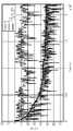
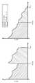
이러한 형태의 대역폭 확장에서, 매우 독특한 고조파 구조의 높은 성조 신호들과 함께 문제점들이 발생한다. 비록 스펙트럼 대역 복제 방법이 스펙트럼의 성조 적응을 위한 기술들을 제공하더라도, 이것은 파괴된 고조파 구조를 복원하는데 충분하지 않다. 결과는 신호 내의 지각가능한 거칠기이다(Wilde, 2009). 이러한 아티팩트들은 청취자에 매우 불쾌하다. 이는 스펙트럼 대역 복제 디코더의 복제 과정으로부터 기원한다. 이는 신호의 고조파 미세 구조를 고려하지 않고 간단하게 기저 대역을 복제한다. 결과가 도 31에 도시된다.In this type of bandwidth extension, problems arise with high gain signals of very unique harmonic structure. Although the spectral band replication method provides techniques for adaptation of the spectrum, it is not sufficient to restore the destroyed harmonic structure. The result is the perceptible roughness in the signal (Wilde, 2009). These artifacts are very unpleasant to the listener. This originates from the replication process of the spectral band replica decoder. This simply replicates the baseband without considering the harmonic fine structure of the signal. The result is shown in Fig.
도 31은 스펙트럼 대역 복제를 갖는 고조파 구조의 파괴를 도시한다. 도 31은 왼쪽 상에 원래의 광대역 스펙트럼을 도시한다. 도 31은 오른쪽 상에 스펙트럼 대역 복제 고주파수 부분 재구성 이후의 스펙트럼을 도시한다.Figure 31 shows the destruction of the harmonic structure with spectral band replication. Figure 31 shows the original wideband spectrum on the left. Figure 31 shows the spectrum after the spectral band replica high frequency portion reconstruction on the right.
고조파들이 컷오프 주파수 위의 범위 내에서 원래의 스펙트럼에 대하여 이동되는 것이 분명하게 식별될 수 있다. 재구성된 고주파수 부분 스펙트럼은 고조파이나, 고조파 구조는 컷오프 주파수에서 부가적인 주파수 스윙(flag)에 의해 확산된다. 부가적으로, 고조파 서브-톤(sub-tone)들의 진폭 비율은 엔밸로프의 재구성에 의해 왜곡된다. 이러한 효과는 바람직하게는 악기에 의해 발생되는 것과 같이, 모든 고조파 신호와 함께 발생할 것이다.It can be clearly identified that the harmonics are shifted with respect to the original spectrum within the range above the cutoff frequency. The reconstructed high-frequency part of the spectrum is harmonic or harmonic structure is spread by the additional frequency swing (flag) in the cut-off frequency. Additionally, the amplitude ratio of the harmonic sub-tones is distorted by the reconstruction of the envelope. This effect will preferably occur with all harmonic signals, such as those generated by a musical instrument.
예를 들면 피치 파이프(pitch pipe)와 같은, 고조파 신호들을 위하여, 스펙트럼 대역 복제 및 등가의 대역폭 확장 방법들은 예를 들면 성조 거칠기 및 불쾌한 음색과 같은, 바람직하지 않은 아티팩트들을 생산하는데, 그 이유는 신호의 고조파 구조가 완전하게 유지되지 않기 때문이다. 독특한 고조파 구조를 나타내는 신호들을 위하여, 스펙트럼 대역 복제를 적용할 때 거칠기 및 음색의 변화 같은, 바람직하지 않은 아티팩트들이 발생한다.For harmonic signals, such as, for example, pitch pipes, spectral band replication and equivalent bandwidth extension methods produce undesirable artifacts, such as, for example, tone roughness and unpleasant tone, Is not completely maintained. For signals representing unique harmonic structures, undesirable artifacts such as roughness and tone changes occur when applying spectral band replication.
이것이 이러한 구조들을 포함하는 다음의 2가지의 시간-도메인 대역폭 확장이 개발된 이유이다: 위상 보코더-제어(phase vocoder-controlled) 고조파 대역폭 확장 및 특별한 측대역 변조를 사용하는 연속적 변조(CM) 대역폭 확장[Nagel 및 Disch, 2009], [Nagel 등, 2010]. 자유롭게 선택가능한 주파수들을 갖는 연속적 변조 때문에, 특히 연속적 변조 대역폭 확장은 뛰어난 고조파 복원을 달성한다.This is why the following two time-domain bandwidth extensions involving these structures have been developed: Continuous Modulation (CM) bandwidth extension using phase vocoder-controlled harmonic bandwidth extension and special sideband modulation [Nagel and Disch, 2009], [Nagel et al., 2010]. Owing to continuous modulation with freely selectable frequencies, in particular continuous modulation bandwidth extension achieves excellent harmonic reconstruction.
비고조파 스펙트럼 연속성의 문제점을 방지하는 일부 대안의 대역폭 확장 방법이 존재한다. 이러한 방법들 중 2가지가 아래에 소개된다. 기본적으로, 이러한 방법들은 도 29의 스펙트럼 대역 복제 디코더의 고주파수 부분 발생기를 대체하고 따라서 단순한 복제 과정에 대한 대안을 표현한다. 스펙트럼 엔벨로프와 성조의 적응은 변하지 않은 채로 남아있다. 입력 신호가 시간 도메인 내에 존재하여야만 하기 때문에, 이러한 방법은 또한 대역폭 확장을 위한 시간 도메인 방법으로서 언급된다.There are some alternative bandwidth extension methods that avoid the problems of non-harmonic spectral continuity. Two of these methods are described below. Basically, these methods replace the high frequency fraction generator of the spectral band replica decoder of Figure 29 and thus represent an alternative to a simple replication process. The adaptation of the spectrum envelope and the spectrum remains unchanged. Since the input signal must be in the time domain, this method is also referred to as a time domain method for bandwidth extension.
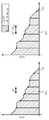
고조파 대역폭 확장(HBE)이 먼저 언급된다. 고조파 대역폭 확장은 고-피치 범위를 생산하기 위하여 위상 보코더를 사용한다. 스펙트럼은 위상 보코더를 적용함으로써 확장된다. 도 32의 왼쪽 상에 도시된 것과 같이, 기저 대역은 최대 신호 주파수(fmax)까지 확산되고 컷오프 주파수 및 최대 신호 주파수(fmax) 사이의 범위는 클리핑된다(clipped out). 스펙트럼은 그리고 나서 상기 부분과 기저 대역으로 구성된다(예를 들면, 도 32의 오른쪽). 엔벨로프는 또한 스펙트럼 대역 복제에서 수행되는 것과 같이 적용된다(Nagel 및 Disch, 2009).Harmonic bandwidth extension (HBE) is mentioned first. Harmonic bandwidth expansion uses a phase vocoder to produce a high-pitch range. The spectrum is extended by applying a phase vocoder. As shown on the left side of FIG. 32, the baseband signal has a range between a maximum frequency (fmax) spreading the cut-off frequency and the maximum signal frequency (fmax) is clipped to the (clipped out). The spectrum is then composed of the part and the baseband (e.g., the right side of Figure 32). Envelopes are also applied as performed in spectral band replication (Nagel and Disch, 2009).
도 32는 고조파 대역폭 확장-고주파 부분 재구성을 개략적으로 도시한다. 도 32는 왼쪽 상에 인자(2)에 의한 기저 대역의 확장을 도시한다. 도 32는 오른쪽 상에 스펙트럼 엔벨로프를 적용한 이후의 스펙트럼을 도시한다. Figure 32 schematically illustrates harmonic bandwidth extension-high frequency fractional reconstruction. 32 shows the expansion of the baseband by the factor (2) on the left. Figure 32 shows the spectrum after applying the spectral envelope on the right.
적분 확장 인자(σ∈N+)의 사용은 컷오프 주파수(fg)가 고조파 구조를 변경하지 않는 것을 보장한다. 다음이 적용된다:The use of the integral extension factor (sigma N+ ) ensures that the cutoff frequency fg does not change the harmonic structure. The following applies:
fmax = σ·fg (3.1)fmax =? fg (3.1)
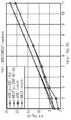
단점은 도 33에 도시된 것과 같이, 서브-톤들 사이의 거리가 스펙트럼의 확산에 의해 확장 인자로 변경된다는 사실이다. 게다가, 스펙트럼을 확산시키기 위하여 복잡한 계산이 필요하다. 이들 중에서 고-해상도 이산 푸리에 변환, 위상 적응 및 샘블 레이트 전환이 존재한다(Dolson, 1986). 오디오 신호가 블록들로 세분될 때, 이웃하는 블록들의 위상을 연속적으로 계속할 수 있도록 하기 위하여 부가적으로 중첩-가산 구조가 필요하다. 고도의 성조 신호들을 위하여, 위상 보코더 기술을 사용하여 매우 뛰어난 결과들이 달성될 수 있으나, 충격 신호(percussive signal)들에서 트랜지언트 블러(blur) 및 개별 트랜지언트 처리의 실행이 필요하다(Wilde, 2009).The disadvantage is the fact that the distance between sub-tones, as shown in Figure 33, is changed by an extension of the spectrum into an extension factor. In addition, complex calculations are needed to spread the spectrum. Of these, high-resolution discrete Fourier transform, phase adaptation and sampletransition exist (Dolson, 1986). When the audio signal is subdivided into blocks, an overlap-add structure is additionally required in order to be able to continue the phase of the neighboring blocks continuously. Very good results can be achieved using a phase vocoder technique for high-gain signals, but it is necessary to perform transient blur and individual transient processing on percussive signals (Wilde, 2009).
도 33은 고조파 대역폭 확장을 갖는 고조파 구조를 도시한다. 도 33은 왼쪽 상에 원래의 광대역 스펙트럼을 도시한다. 도 33은 오른쪽 상에 고조파 대역폭 확장 고주파수 부분 재구성 이후의 스펙트럼을 도시한다.Figure 33 shows a harmonic structure with harmonic bandwidth extension. Figure 33 shows the original wideband spectrum on the left. Figure 33 shows the spectrum after harmonic bandwidth extension and high frequency portion reconstruction on the right.
연속적인 단일 측대역 변조가 아래에 설명될 것이다.Continuous single sideband modulation will be described below.
연속적으로 변조되는 대역폭 확장(CM-BWE)은 대역폭 확장을 위한 또 다른 시간-도메인 방법이다. 이러한 방법에서, 기저 대역은 단일 측대역 변조에 의한 주파수(fmod)에 의해 변조되고 따라서 도 34에 도시된 것과 같이, 또 다른 스펙트럼 위치로 이동된다. 가변 변조 주파수는 대역폭-확장된 신호의 고조파 구조가 유지되는 것을 보장한다. 컷오프 주파수(fg)보다 큰 변조 주파수들과 함께, 스펙트럼 내에 형성하는 갭(gap)은 잡음으로 채워져야만 한다(Nagel 등, 2010).The continuously modulated bandwidth extension (CM-BWE) is another time-domain method for bandwidth extension. In this way, the baseband is modulated by frequency (fmod ) by single sideband modulation and is therefore shifted to another spectral location, as shown in Fig. The variable modulation frequency ensures that the harmonic structure of the bandwidth-extended signal is maintained. With modulating frequencies greater than the cutoff frequency fg , the gaps that form in the spectrum must be filled with noise (Nagel et al., 2010).
도 34는 연속적으로 변조되는 대역폭 확장 재구성을 개략적으로 도시한다. 도 34는 왼쪽 상에 주파수(fmod)를 갖는 기저 대역의 변조를 도시한다. 도 34는 오른쪽 상에 스펙트럼 엔벨로프의 적응 이후의 스펙트럼을 도시한다.Figure 34 schematically illustrates bandwidth extension reconfiguration that is continuously modulated. Figure 34 shows modulation of the baseband with frequency (fmod ) on the left. Figure 34 shows the spectrum after adaptation of the spectral envelope on the right.
도 34에 도시된 경우를 제외하고, 기저 대역이 또한 몇 번 변조되는 것이 필요할 수 있다. 그러한 경우에 있어서, 각각의 그 다음 다중 적분이 선택되는 모든 변조를 위하여 변조 주파수가 적용되어야만 한다(Nagel 등, 2010). 변조 이전에, 허용된 신호 주파수(fmax)가 변조 후에 초과하지 않도록 하기 위하여, 기저 대역은 변조 주파수에 따른 로-패스에 의해 필터링되어야만 한다. 이미 나타낸 방법들과 유사하게, 그 뒤에 스펙트럼 엔벨로프가 형성되고 조성이 적용된다.Except in the case shown in Fig. 34, it may be necessary that the baseband is also modulated several times. In such a case, the modulation frequency must be applied for every modulation where each of the following multiple integrals is selected (Nagel et al., 2010). In order to ensure that the allowed signal frequency fmax does not exceed after modulation before modulation, the baseband must be filtered by low-pass along the modulation frequency. Similar to the methods already shown, the spectrum envelope is then formed and the composition applied.
도 35는 연속적으로 변조되는 대역폭 확장에 의해 확장된 신호 내에서 형성되는 것과 같은 고조파 구조를 도시한다. 도 35는 왼쪽 상에 원래의 광대역 스펙트럼을 도시한다. 도 35는 오른쪽 상에 연속적으로 변조되는 대역폭 확장 고주파수 부분 재구성 이후의 스펙트럼을 도시한다. 고조파 대역폭 확장에서와 같이, 연속적으로 변조되는 대역폭 확장은 스펙트럼 내에 고조파 서브-톤이 없다. 그러나, 이는 부정적인 방법으로 이목을 끌지 않는데, 그 이유는 고조파 구조 자체가 유지되기 때문이다.Figure 35 illustrates a harmonic structure such as that formed in an extended signal by a bandwidth extension that is continuously modulated. Figure 35 shows the original broadband spectrum on the left. Figure 35 shows the spectrum after bandwidth extended high frequency portion reconstruction continuously modulated on the right side. As in the harmonic bandwidth extension, the continuously modulated bandwidth extension does not have harmonic sub-tones within the spectrum. However, this does not attract attention in a negative way, because the harmonic structure itself is maintained.
이러한 방법이 갖는 단점은 단일 측대역 변조를 계산하는 것이다. 정확한 계산을 위하여 분석 신호, 즉 양성 주파수들만을 포함하는 신호가 필요하다. 그러한 신호를 계산하기 위하여 힐버트 변환기(hilbert transformer)가 필요하다. 이는 기본적으로 무한 임펄스 응답의 비-인과적 필터이다. 그러한 필터는 실현될 수 없고 단순화되어야만 한다. 그럼에도 불구하고 최소 필터 순서로 가능한 한 높은 저지 대역을 달성하기 위하여, 필터의 인과관계에 의해 신호에 무시할 수 없는 지연이 추가된다(Wilde, 2009).The disadvantage of this method is the calculation of the single sideband modulation. For accurate calculation, an analysis signal, i.e. a signal containing only positive frequencies, is needed. A hilbert transformer is needed to compute such a signal. This is basically a non-causal filter of an infinite impulse response. Such a filter can not be realized and must be simplified. Nonetheless, in order to achieve as high a stopband as possible with the minimum filter order, a causal relationship of the filter adds a non-negligible delay to the signal (Wilde, 2009).
그러나, 시간 도메인 내에 주파수 이동이 실현될 때, 이는 매우 복잡할 수 있다. 그에 반해 부대역 오디오 인코더의 부대역 도메인 내의 이동의 실현은 주파수 해상도가 필요한 주파수 이동을 위하여 너무 조잡하도록 야기할 수 있다.However, when frequency movement is realized within the time domain, this can be very complex. On the other hand, the realization of movement within sub-band domains of sub-band audio encoders can cause frequency resolution to be too coarse for the required frequency movement.
바람직한 것은 오디오 신호들을 인코딩함으로써 필요한 디지털 데이터의 메모리 공간 또는 상기 데이터를 전송하는데 필요한 대역폭을 최소화하는 것이다. 동시에, 재생된 오디오 신호의 지각 품질은 CD 표준에 필적해야만 한다(16 비트의 양자화 깊이에서 샘플링 주파수 44100 ㎐). 따라서, 품질은 데이터 비율의 감소에서 최대화된다.
What is desired is to minimize the memory space of the necessary digital data or the bandwidth required to transmit the data by encoding the audio signals. At the same time, the perceptual quality of the reproduced audio signal must match the CD standard (sampling frequency 44100 Hz at 16 bit quantization depth). Thus, the quality is maximized in the reduction of the data rate.
결론적으로, 본 발명의 목적은 부대역 도메인 내에서 자유롭게 선택가능한 주파수 이동들을 위한 향상된 개념들을 제공하는 것이다. 본 발명의 목적은 청구항 1항에 따른 장치, 청구항 23항에 따른 방법 및 청구항 24항에 따른 컴퓨터 프로그램에 의해 달성된다.
In conclusion, it is an object of the present invention to provide improved concepts for freely selectable frequency shifts within a subband domain. The object of the invention is achieved by a device according to
오디오 입력 신호를 기초로 하여 주파수-이동된 오디오 신호를 생산하기 위한 장치가 제공된다. 복수의 제 1 부대역을 위하여, 오디오 입력 신호는 여기서는 하나 또는 몇몇 부대역 값들에 의해 표현될 수 있다. 장치는 인터페이스 및 주파수-이동 유닛(frequency-shifting unit)을 포함한다. 인터페이스는 오디오 입력 신호를 수신하도록 구성된다. 주파수-이동 유닛은 주파수 이동된 오디오 신호를 생산하도록 구성되며, 복수의 제 2 부대역을 위하여, 주파수 이동된 오디오 신호는 각각 하나 또는 몇몇 제 2 부대역 값들을 포함한다. 게다가, 각각의 제 1 및 제 2 부대역 값들은 하나의 각각의 위상 각에 대한 정보를 포함한다. 주파수-이동 유닛은 부가적으로 상기 제 2 부대역 값의 제 2 위상 각이 위상 각 차이에 의해 상기 제 1 부대역 값의 제 1 위상 각과 다를 수 있는 것과 같이 제 1 부대역 값들 중 하나를 기초로 하여 제 2 부대역 값들 중 하나를 생산하도록 구성되며, 위상 각 차이는 주파수-이동된 오디오 신호를 획득하기 위하여 어떠한 주파수 차이에 의해 오디오 입력 신호가 이동되는지를 나타내는 주파수 정보에 의존하고, 위상 각 차이는 제 1 부대역들 중 하나의 주파수 대역폭에 의존한다.An apparatus is provided for producing a frequency-shifted audio signal based on an audio input signal. For a plurality of first subbands, the audio input signal may be represented here by one or several subband values. The apparatus includes an interface and a frequency-shifting unit. The interface is configured to receive an audio input signal. The frequency-shifting unit is configured to produce a frequency shifted audio signal, and for a plurality of second sub-bands, the frequency shifted audio signal comprises one or several second sub-band values, respectively. In addition, each of the first and second sub-band values includes information for one respective phase angle. The frequency-shifting unit may additionally be based on one of the first sub-band values, such that the second phase angle of the second sub-band value may be different from the first phase angle of the first sub- To produce one of the second sub-band values, the phase angle difference depending on frequency information indicating which audio input signal is shifted by some frequency difference to obtain a frequency-shifted audio signal, The difference depends on the frequency bandwidth of one of the first subbands.
실시 예들은 대역폭 확장을 위한 향상된 개념들을 제공하며, 이러한 향상된 개념들은 뒤에 "고조파 스펙트럼 대역폭 확장" 또는 "HSBE"로서 언급된다. 주파수 도메인 내의 이러한 개발된 고조파 대역폭 확장은 바람직하지 않은 아티팩트들의 억제를 허용한다. 여기서 복제된 스펙트럼은 원래의 고조파 구조가 유지되는 것과 같이 변조된다. 다른 방법들과 대조적으로, 고조파 스펙트럼 대역폭 확장은 변형 이산 코사인 변환 도메인 내의 신호 표현을 기초로 할 수 있으며 따라서 효율적인 구현을 허용한다. 고조파로 정확한 대역폭 확장은 뒤따르는 변조를 갖는 스펙트럼 값들의 복제 과정에 의해 달성된다.Embodiments provide improved concepts for bandwidth extension, and these enhanced concepts are referred to hereinafter as "Harmonic Spectrum Bandwidth Expansion" or "HSBE ". This developed harmonic bandwidth extension in the frequency domain allows suppression of undesirable artifacts. Where the replicated spectrum is modulated such that the original harmonic structure is maintained. In contrast to other methods, the harmonic spectral bandwidth extension can be based on signal representations within the modified discrete cosine transform domain and thus allows efficient implementation. Accurate bandwidth extension at harmonics is achieved by the process of replicating spectral values with subsequent modulation.
일 실시 예에 따르면, 오디오 인코더들에서 이미 실현된 변형 이산 코사인 변환의 부대역 도메인이 사용된다. 이러한 방법으로, 변환은 부가적인 복잡도 또는 지연을 야기하지 않는다.According to one embodiment, the subband domain of the transformed discrete cosine transform already realized in the audio encoders is used. In this way, the transformation does not cause additional complexity or delay.
부대역 대역폭의 짝수 다중 적분에 의해 신호가 이동될 때, 실시 예들에서 낮은 주파수들의 부대역 신호들이 상응하는 높은 주파수 대역들로 이동된다.When the signal is moved by the even multiple integration of the subband bandwidth, in the embodiments the subband signals of the lower frequencies are shifted to the corresponding higher frequency bands.
부대역 대역폭의 홀수 다중 적분에 의해 신호가 이동될 때, 실시 예들에서 복제되려는 부대역 신호들의 모든 제 2 샘플 값에 역 기호(시간의 방향에서, 블록 지수의 증가)가 제공된다. 이러한 방법으로, 주파수-이동되고 복제된 신호를 위하여 변형 이산 코사인 변환 필터 뱅크의 에일리어싱 취소 특성이 여전히 작동한다.When the signal is moved by the odd multiple integration of the subband bandwidth, a reverse sign (in the direction of time, an increase in the block index) is provided for all second sample values of the subband signals to be duplicated in the embodiments. In this way, the aliasing cancellation property of the transformed discrete cosine transform filter bank still operates for the frequency-shifted and replicated signal.
부대역 대역폭의 다중 비-적분에 의해 낮은 주파수들의 신호들이 이동될 때, 실시 예들에서 낮은 주파수들의 부대역들의 복소수 값의 버전이 생산되고, 이들의 카피(copy)가 만들어지며, 복소수 지수 함수에 의해 변조되며(곱해진다), 상기 복소수 지수 함수는 부대역 대역폭의 그 다음 다중 적분의 주파수의 차이와 상응하는 주파수이다(이는 균열된 부대역 대역폭 이동이다). 그러나, 이에 의해 변형 이산 코사인 변환 필터 뱅크의 에일리어싱 보상 특성이 영향을 받거나 또는 파괴된다.When signals of low frequencies are shifted by multiple non-integration of subband bandwidth, in embodiments, a version of a complex value of subbands of low frequencies is produced, a copy of which is produced, and a complex exponential function (Multiplied), and the complex exponential function is the frequency corresponding to the difference in frequency of the next multiple integration of the subband bandwidth (which is a cracked subband bandwidth shift). However, this causes the aliasing compensation characteristic of the transformed discrete cosine transform filter bank to be affected or destroyed.
결과로서 생기는 주파수 왜곡을 방지하거나 또는 감소시키기 위하여, 이웃하는 부대역 신호들 사이에 폴딩 같은 처리가 실행되며, 하나의 부대역 신호의 가중된 버전은 그것의 이웃 내의 부대역의 부대역 신호에 더하며. 따라서 이는 에일리어싱 성분의 역 기호를 나타내고, 따라서 에일리어싱은 보상되거나 또는 감소된다. 일 실시 예에서, 가중치들은 여기서 바람직하게 균열된 주파수 이동과 상응한 것과 같이 선택된다.In order to prevent or reduce the resulting frequency distortion, a process such as folding between neighboring subband signals is performed, and a weighted version of one subband signal is added to the subband signal of the subband in its neighborhood And. Thus, it represents the inverse sign of the aliasing component, and thus the aliasing is compensated or reduced. In one embodiment, the weights are selected here as being corresponding to the preferably cracked frequency shift.
스펙트럼의 변조는 변형 이산 코사인 변환의 TDAC 특성을 위반하고, 그 결과는 에일리어싱 성분들이다. 이들을 제거하기 위하여, 실시 예들에서 에일리어싱 취소를 위한 유한 임펄스 응답 필터 구조가 제공된다. 이를 위하여 필요한 필터 임펄스 응답들은 연속적 근사화(successive approximation)에 의해 최적화되고 예를 들면, 룩-업(look-up) 테이블로서 저장된다.The modulation of the spectrum violates the TDAC characteristic of the transformed discrete cosine transform, and the result is the aliasing components. To remove them, embodiments provide finite impulse response filter structures for aliasing cancellation. The filter impulse responses required for this are optimized by a successive approximation and stored, for example, as a look-up table.
그러나, 여기에 존재하는 개념들의 적용을 위하여, 인코딩 과정, 즉, 바람직하게는 음향심리학적 모델의 적용에 의한 데이터의 압축을 적용하는 것이 필요하지 않다.However, for the application of the concepts present here, it is not necessary to apply compression of the data by the encoding process, preferably the application of the psychoacoustic model.
제공되는 개념들은 이미 존재하는 대역폭 확장방법들을 기초로 하고 이를 향상시킨다. 이러한 새로운 방법을 사용하여, 일정한 저장 요구사항을 갖는, 재생되는 오디오 재료의 품질을 증가시키는 것이 가능하다. 인코딩 과정은 여기서는 영향을 받지 않으나, 디코더는 뒤에 개발된다. 개발된 방법은 고조파 대역폭 확장을 실현한다. 이는 고효율 고급 오디오 코딩에서 사용되는 것과 같이, 스펙트럼 대역 복제를 기초로 한다.The concepts provided are based on and enhance existing bandwidth extension methods. Using this new method, it is possible to increase the quality of the audio material being reproduced, with certain storage requirements. The encoding process is not affected here, but the decoder is developed later. The developed method realizes harmonic bandwidth extension. It is based on spectral band replication, as used in high efficiency advanced audio coding.
제공되는 본 발명의 효율적인 스펙트럼 대역 복제 개념들은 원래 스펙트럼의 고조파 구조를 유지하고 따라서 종래 스펙트럼 대역 복제 기술의 설명된 아티팩트들을 감소시킨다.The provided efficient spectral band replication concepts of the present invention maintain the harmonic structure of the original spectrum and thus reduce the described artifacts of conventional spectral band replication techniques.
고조파 스펙트럼 대역폭 확장(HSBE)을 위한 개념들이 제공된다. 효율이 중요한 역할을 하기 때문에, 유한 임펄스 응답 필터들에 의해 아티팩트들을 억제하는데 사용되는 필터 뱅크에서 시작하는, 근본적인 신호 처리가 설명될 것이다.Concepts for harmonic spectral bandwidth extension (HSBE) are provided. Since efficiency plays an important role, fundamental signal processing, starting from the filter bank used to suppress artifacts by finite impulse response filters, will be described.
여기서 본 발명의 고조파 스펙트럼 대역폭 확장은 고조파 구조를 지속하는 동안에 오디오 신호의 대역-제한된 스펙트럼을 확장하는 강력하고 효율적인 방법을 제공한다.Here, the harmonic spectral bandwidth extension of the present invention provides a powerful and efficient way to extend the band-limited spectrum of an audio signal while continuing the harmonic structure.
스펙트럼이 고조파로 정확한 방식으로 계속되도록 하기 위하여, 고조파 스펙트럼 대역폭 확장에 대한 다수의 문제점이 명심해야만 한다는 것이 설명될 것이다. 스펙트럼의 고조파 구조를 재구성하기 위한 일부 방법이 알려져 있더라도, 이는 그럼에도 불구하고 신규의 더 효율적인 기술들을 개발하는데 유용하다. 특히 고급 오디오 코딩 또는 통합 음성 및 오디오 코딩) 같은, 현대 오디오 인코더 구조들의 통합을 위하여, 일반적인 조건들에 대한 적용이 필수불가결하다.It will be explained that a number of problems with harmonic spectral bandwidth extension must be kept in mind in order for the spectrum to continue in the correct way with harmonics. Although some methods for reconstructing the harmonic structure of the spectrum are known, this is nevertheless useful for developing new, more efficient techniques. For integration of modern audio encoder structures, such as in particular advanced audio coding or integrated voice and audio coding, the application to general conditions is indispensable.
연속적 고조파 스펙트럼 대역폭 확장의 필수 성분은 발생하는 스퓨리어스 성분들의 억제이다. 이것이 여기서는 이를 위하여 디자인된 기능의 방식 및 에일리어싱 취소의 최적화에 초점을 맞춘 정확한 이유이다. 적절한 유한 임펄스 응답 필터들을 선택함으로써 바람직하지 않은 신호 부분들이 상당히 감소될 수 있다는 것이 알려졌다. 따라서, 종래 기술의 필터링과 대조적으로, 이는 필터 임펄스 응답을 사용하여 중첩된 시간 신호가 아니고, 복소수 변형 이산 코사인 변환/변형 이산 사인 변환 계수들이다. 이러한 방법들이 발생하는 모든 에일리어싱 성분을 취소시킬 수 없더라도, 이는 일부 우세한 스퓨리어스 부분들을 제거하기에 충분하다.An integral component of the continuous harmonic spectral bandwidth extension is suppression of the spurious components that occur. This is the precise reason for focusing on optimizing aliasing cancellation and the way in which functions are designed for this purpose. It has been found that by selecting appropriate finite impulse response filters, undesirable signal portions can be significantly reduced. Thus, in contrast to prior art filtering, this is not a superimposed time signal using a filter impulse response, but rather a complex transformed discrete cosine transform / transform discrete sinusoidal transform coefficients. Although these methods can not cancel all aliasing components that occur, this is sufficient to remove some dominant spurious components.
그 외에도, 변형 이산 코사인 변환 계수들을 변형 이산 사인 변환 스펙트럼 값들로 변환하는 것이 고조파 스펙트럼 대역폭 확장의 또 다른 중요한 요소이다. 현대 오디오 인코더들은 변형 이산 코사인 변환 도메인 내에 독점적으로 작동한다. 신호는 그것의 스펙트럼 표현 내에서 충분히 정확하게 기술되나, 그럼에도 불구하고 이러한 정보는 고조파 스펙트럼 대역폭 확장을 사용하여 스펙트럼을 복제하는데 중분하지 않다. 위상 형태는 부가적인 변형 이산 코사인 변환 값들에 의해서만 변형될 수 있다. 여기서는 고정 지연을 사용하여, 종래의 변형 이산 코사인 변환 값들로부터 가능한 한 효율적으로 손실 변형 이산 코사인 변환 계수들의 계산을 허용하는 변환이 도입된다. 정확한 해결책 이외에도, 오류 발생이 쉬운, 그러나 자원 절약 대안들이 존재할 수 있다.In addition, transforming the transformed discrete cosine transform coefficients to modified discrete cosine transform spectral values is another important component of the harmonic spectral bandwidth extension. Modern audio encoders operate exclusively within a modified discrete cosine transform domain. The signal is described sufficiently accurately in its spectral representation, but nevertheless this information is not neglected to replicate the spectrum using a harmonic spectral bandwidth extension. The phase shape can be modified only by additional transformed discrete cosine transformed values. Here, using a fixed delay, a transformation is introduced that allows the calculation of lossy transform discrete cosine transform coefficients as efficiently as possible from conventional modified discrete cosine transformed values. In addition to the correct solution, there may be some error-prone, but resource-saving alternatives.
스펙트럼의 변조는 고조파 스펙트럼 대역폭 확장과 함께 중요하다. 이는 스펙트럼의 효율적인 복제를 위하여 두 가지 단계가 유용하다는 것을 나타낸다. 한편으로, 스펙트럼은 적분 변형 이산 코사인 변환 부대역들에 의해 이동되고, 다른 한편으로, 시간 해상도를 위하여 변형 이산 코사인 변환 부대역의 대역폭 내의 변조가 실행된다. CD 품질 내의 신호들을 위하여, 이러한 기술로 달성된 해상도는 약 0.5 ㎐이다. 이는 스펙트럼의 고조파 구조가 고도로 정확하게 복제될 수 있다는 것을 의미한다.The modulation of the spectrum is important with the extension of the harmonic spectral bandwidth. This indicates that two steps are useful for efficient replication of the spectrum. On the other hand, the spectrum is shifted by the integral transform discrete cosine transform subbands and, on the other hand, modulation in the bandwidth of the transformed discrete cosine transform subbands is performed for temporal resolution. For signals in CD quality, the resolution achieved with this technique is about 0.5 Hz. This means that the harmonic structure of the spectrum can be replicated with a high degree of accuracy.
변조를 결정하기 위하여 필요한 래그 주파수는 바람직하게는 인코더에 의해 제공될 수 있다.The lag frequency needed to determine the modulation can preferably be provided by the encoder.
실시 예들에서, 주파수-이동된 신호를 생산하기 위하여 시스템, 장치 또는 방법 또는 컴퓨터 프로그램이 제공되고, 부대역 분해가 사용되며, 균열된 부대역 대역폭 이동들을 위하여, 부대역들이 복소수 지수 함수에 의한 곱셈에 의해 곱해진다.In embodiments, a system, apparatus, or method or computer program is provided for producing a frequency-shifted signal, wherein subband decomposition is used and for subband bandwidth shifts, subbands are multiplied by a complex exponential function ≪ / RTI >
실시 예들에서, 에일리어싱 성분들은 이웃하는 부대역 신호들 사이에 버터플라이 처리(butterfly processing)를 실행함으로써 보상되거나 또는 적어도 감소된다.In embodiments, the aliasing components are compensated or at least reduced by performing butterfly processing between neighboring subband signals.
또 다른 실시 예들에 따르면, 주파수 이동은 오디오 인코딩 시스템의 부대역 도메인 내에서 실행된다.According to yet another embodiment, the frequency shift is performed within the subband domain of the audio encoding system.
실시 예들에서, 주파수 이동은 오디오 인코딩 시스템 내의 신호의 주파수 표현의 손실 주파수 부분들 및/또는 스펙트럼 홀(spectrum hole)들을 충족시키도록 사용된다.In embodiments, the frequency shift is used to satisfy the loss frequency portions and / or the spectrum holes of the frequency representation of the signal in the audio encoding system.
실시 예들에 따르면, 주파수 이동은 재생 속도를 변경하기 위한 샘플 레이트 전환과 조합하여 사용되고, 피치는 그대로 남아있다.According to embodiments, the frequency shift is used in combination with sample rate switching to change the playback speed, and the pitch remains the same.
바람직하게는 처음에 주파수 이동에 의해 주파수를 증가시키고 그리고 나서 재생 속도를 감소시킬 때, 오디오 데이터의 특정 양의 재생 시간은 일정한 피치와 함께 길러질 것이다. 다른 한편으로, 바람직하게는 처음에 주파수 이동에 이해 주파수를 감소시키고 그리고 나서 오디오 데이터의 특정 양의 재생 시간을 증가시킬 때, 재생 시간은 일정 피치와 함께 짧아질 것이다.Preferably, when initially increasing the frequency by frequency shifting and then reducing the playback speed, the playback time of a certain amount of audio data will be raised with a constant pitch. On the other hand, the playback time will be shortened with a constant pitch, preferably when initially reducing the understanding frequency to frequency shift and then increasing the playback time of a certain amount of audio data.
또 다른 실시 예들에서, 음악 신호를 미세조정하기 위한 개념들이 사용된다. 제공되는 개념들은 바람직하게는 특히 오디오 조율을 위한 바람직한 방식으로 사용될 수 있다. 예를 들면, 디지털 음악 신호의 단지 작은 피치 변화들, 즉 바람직하게는, 부대역의 대역폭보다 작은, 바람직하게는 변형 이산 코사인 변환 또는 직교 미러 필터 뱅크 부대역보다 작은 주파수 변화들만이 실현될 때, 특히 장점인 개념들이 제공된다.In still other embodiments, concepts for fine tuning the music signal are used. The concepts provided may preferably be used in a preferred manner, especially for audio tuning. For example, when only small pitch variations of the digital music signal, i.e., preferably less than the bandwidth of the subband, preferably only the frequency transformations less than the modified discrete cosine transform or the quadrature mirror filter bank subband, Concepts that are particularly advantageous are provided.
실시 예들에 따르면, 개념들은 스펙트럼의 작은 주파수 부분들의 복제 또는 주파수 이동에 의해 스펙트럼의 더 높은 주파수들을 생산하도록 사용된다.According to embodiments, the concepts are used to produce higher frequencies of the spectrum by copying or frequency shifting small frequency portions of the spectrum.
실시 예들에서, 부대역 분해는 변형 이산 코사인 변환(MDCT)이다.In embodiments, subband decomposition is transformed discrete cosine transform (MDCT).
또 다른 실시 예들에서, 부대역 분해는 다위상 직교 미러 필터 뱅크(QMF)이다.In yet other embodiments, subband decomposition is a multi-phase quadrature mirror filter bank (QMF).
위의 실시 예들에서 제공되는 개념들은 그중에서도 시스템, 장치 또는 방법 또는 컴퓨터 프로그램 모두로서 실현될 수 있다.The concepts provided in the above embodiments may be realized as a system, an apparatus or a method, or a computer program, among others.
고조파 스펙트럼 대역폭 확장의 실행가능한 구현은 알고리즘들과 기능적 원리들을 기초로 하여 형성되었고 개발되었다.A feasible implementation of harmonic spectral bandwidth extension has been formed and developed based on algorithms and functional principles.
매트랩(Matlab) 또는 프로그래밍 언어 C 또는 또 다른 프로그램 언어에서의 실시간 구현이 가능하다. 이는 제공되는 개념들이 실시간 시스템에서 적용될 수 있다는 것을 의미한다. 또한 스펙트럼 대역 복제의 경우와 마찬가지로, 재생되는 신호의 품질은 이러한 방법들을 사용하여 증가될 것으로 기대된다.Real-time implementation in MATLAB or programming language C or another programming language is possible. This means that the concepts provided can be applied in a real-time system. Also, as in the case of spectral band replication, the quality of the reproduced signal is expected to be increased using these methods.
제공되는 개념들에 따른 스펙트럼의 변조의 복잡도는 매우 뛰어난 값을 제공한다. 계산 복잡도는 여기서는 주로 변형 이산 코사인 변환-변형 이산 사인 변환 변환에 의존한다.
The complexity of the modulation of the spectrum according to the concepts provided provides a very good value. The computational complexity here depends primarily on the transformed discrete cosine transform-transform discrete cosine transform transform.
게다가, 오디오 입력 신호를 기초로 하여 주파수-이동된 오디오 신호를 생산하기 위한 방법이 제공되는데, 복수의 제 2 부대역을 위하여, 오디오 입력 신호는 하나 또는 몇몇 제 1 부대역 값들에 의해 표현될 수 있다.In addition, a method for producing a frequency-shifted audio signal based on an audio input signal is provided, wherein for a plurality of second sub-bands, the audio input signal can be represented by one or several first sub- have.
방법은:Way:
오디오 입력 신호를 수신하는 단계, 및Receiving an audio input signal, and
주파수-이동된 오디오 신호를 생산하는 단계를 구비하되, 복수의 제 2 부대역을 위하여, 주파수-이동된 오디오 신호는 하나 또는 몇몇 제 1 부대역 값들에 의해 표현되는, 단계를 포함하며,Shifted audio signal, the frequency-shifted audio signal being represented by one or several first sub-band values, for a plurality of second sub-bands,
각각의 제 1 및 제 2 부대역 값들은 각각 하나의 위상 각에 대한 정보를 포함하며,Each first and second subband values each including information on one phase angle,
제 2 부대역 값들 중 하나는 이러한 제 2 부대역 값의 제 2 위상 각이 위상 각 차이에 의해 제 1 부대역 값의 제 1 위상 각과 다를 수 있는 것과 같이 제 1 부대역 값들 중 하나를 기초로 하여 생산되며, 위상 각 차이는 주파수-이동된 오디오 신호를 획득하기 위하여 어떠한 주파수 차이에 의해 오디오 입력 신호가 이동되는지를 나타내는 주파수 정보에 의존하고, 위상 각 차이는 제 1 부대역들 중 하나의 주파수 대역폭에 의존한다.One of the second sub-band values may be based on one of the first sub-band values, such that the second phase angle of the second sub-band value may be different from the first phase angle of the first sub- Wherein the phase angle difference is dependent on frequency information indicating how the audio input signal is moved by some frequency difference to obtain a frequency-shifted audio signal, and the phase angle difference is dependent on one of the first subbands It depends on bandwidth.
게다가, 컴퓨터 프로그램이 컴퓨터 또는 신호 프로세서 상에서 실행될 때, 위의 방법을 실행하기 위한 컴퓨터 프로그램이 제공된다.In addition, when a computer program is executed on a computer or a signal processor, a computer program for executing the above method is provided.
바람직한 실시 예들이 종속 항들에서 설명된다.
Preferred embodiments are described in the dependent claims.
도면들을 참조하여 바람직한 실시 예들이 아래에 설명될 것이다.
도 1a는 일 실시 예에 따른 대역폭 확장을 위한 장치를 도시한다.
도 1b는 일 실시 예에 따른 대역폭 확장을 위한 장치를 도시하며, 장치는 주파수-확장된 오디오 신호를 생산하도록 구성된다.
도 2는 일 실시 예에 따른 고조파 스펙트럼 대역 확장-고주파 부분 재구성을 개략적으로 도시한다.
도 3은 일 실시 예에 따라 주파수-이동된 오디오 신호를 생산하기 위한 장치(300)를 도시한다.
도 4는 일 실시 예에 따른 변형 이산 코사인 변환-변형 이산 사인 변환 변환 매트릭스의 추정을 도시한다.
도 5는 일 실시 예에 따른 변형 이산 코사인 변환-변형 이산 사인 변환 변환 매트릭스의 임펄스 응답들을 도시한다.
도 6은 백색 잡음을 위한 변형 이산 사인 변환 스펙트럼의 추정을 도시한다.
도 7은 일 실시 예에 따른 고조파 스펙트럼 대역 확장을 갖는 고조파 구조를 도시한다.
도 8은 일 실시 예에 따라 확장된 고조파 스펙트럼 대역 확장-고주파수 부분 재구성의 다이어그램을 도시한다.
도 9는 Φ=45o를 위한 에일리어싱 성분들을 도시한다.
도 10은 일 실시 예에 따른 항-에일리어싱 필터의 필터 임펄스 응답을 도시한다.
도 11은 일 실시 예에 따라 Φ=90o를 위한 사인 신호에 대한 항-에일리어싱 필터링의 영향을 도시한다.
도 12는 일 실시 예에 따른 에일리어싱 감소를 위한 버터플라이 구조를 도시한다.
도 13은 일 실시 예에 따른 고조파 스펙트럼 대역 확장-선형 예측 코딩 엔벨로프 적응을 도시한다.
도 14는 고조파 스펙트럼 대역 확장에서 변조 및 항-에일리어싱 필터링의 복잡도를 도시한다.
도 15는 고속 변형 이산 코사인 변환-변형 이산 사인 변환의 복잡도를 도시한다.
도 16은 변형 이산 코사인 변환-변형 이산 사인 변환 변환의 복잡도를 도시한다.
도 17은 변환 길이에 의존하여 고조파 스펙트럼 대역 확장 내의 나머지 외란(disturbance)을 도시한다.
도 18은 고조파 스펙트럼 대역 확장 및 스펙트럼 대역 복제의 비교를 도시한다.
도 19는 고속 일반 이산 코사인 변환-Ⅲ/이산 사인 변환-Ⅲ 구조를 도시한다.
도 20은 고속 이산 코사인 변환-Ⅳ 구조를 도시한다.
도 21은 시간적 마스킹을 개략적으로 도시한다.
도 22는 인간 청각에서의 주파수-의존 마스킹을 개략적으로 도시한다.
도 23은 음향심리학적 오디오 인코더의 블록 회로 다이어그램을 도시한다.
도 24는 음향심리학적 오디오 디코더의 블록 회로 다이어그램을 도시한다.
도 25는 nd 샘플들의 시스템 지연을 갖는 필터 뱅크를 도시한다.
도 26은 다위상 필터 뱅크를 도시한다.
도 27은 대역폭 확장의 범주들을 도시한다.
도 28은 확장된 스펙트럼 대역 복제 인코더의 블록 회로 다이어그램을 도시한다.
도 29는 스펙트럼 대역 복제에 의해 확장된 디코더의 블록 회로 다이어그램을 도시한다.
도 30은 스펙트럼 대역 복제 고주파수 부분 재구성을 개략적으로 도시한다.
도 31은 스펙트럼 대역 복제를 갖는 고조파 구조의 파괴를 도시한다.
도 32는 고조파 대역폭 확장 고주파수 부분 재구성을 개략적으로 도시한다.
도 33은 고조파 대역폭 확장을 갖는 고조파 구조를 도시한다.
도 34는 연속적 변조-대역폭 확장 고주파수 부분 재구성을 개략적으로 도시한다.
도 35는 연속적 변조-대역폭 확장을 갖는 고조파 구조를 도시한다.Preferred embodiments will be described below with reference to the drawings.
1A shows an apparatus for bandwidth extension according to one embodiment.
FIG. 1B illustrates an apparatus for bandwidth extension according to an embodiment, wherein the apparatus is configured to produce a frequency-extended audio signal.
2 schematically illustrates a harmonic spectral band extension-high frequency part reconstruction according to an embodiment.
FIG. 3 illustrates an
4 shows an estimate of a transformed discrete cosine transform-transformed discrete transform transform matrix according to one embodiment.
FIG. 5 illustrates impulse responses of a transformed discrete cosine transform-transformed discrete transform transform matrix according to an embodiment.
6 shows an estimate of the transformed discrete cosine transform spectrum for white noise.
7 illustrates a harmonic structure with a harmonic spectral band extension according to an embodiment.
FIG. 8 illustrates a diagram of an extended harmonic spectral band extension-high frequency fractional reconstruction in accordance with one embodiment.
Figure 9 illustrates the aliasing components for Φ = 45o.
10 illustrates a filter impulse response of an anti-aliasing filter according to one embodiment.
11 illustrates the effect of anti-aliasing filtering on a sine signal for [phi] = 90o according to one embodiment.
12 illustrates a butterfly structure for aliasing reduction according to one embodiment.
13 illustrates a harmonic spectral band extension-linear predictive coding envelope adaptation according to one embodiment.
Figure 14 illustrates the complexity of modulation and anti-aliasing filtering in a harmonic spectral band extension.
Fig. 15 shows the complexity of fast transformed discrete cosine transform-transformed discrete sinusoid transform.
16 shows the complexity of a transformed discrete cosine transform-transformed discrete cosine transform transform.
Figure 17 shows the remaining disturbance in the harmonic spectral band extension depending on the conversion length.
Figure 18 shows a comparison of harmonic spectral band extension and spectral band replication.
FIG. 19 shows a fast general discrete cosine transform-III / discrete cosine transform-III structure.
20 shows a fast discrete cosine transform-IV structure.
Figure 21 schematically shows temporal masking.
Figure 22 schematically shows frequency-dependent masking in human hearing.
Figure 23 shows a block circuit diagram of a psychoacoustic audio encoder.
24 shows a block circuit diagram of an acoustic psychological audio decoder.
Figure 25 shows a filter bank with a system delay of nd samples.
Figure 26 shows a polyphase filter bank.
Figure 27 shows the categories of bandwidth extension.
28 shows a block circuit diagram of an extended spectral band replica encoder.
Figure 29 shows a block circuit diagram of a decoder extended by spectral band replication.
Figure 30 schematically shows spectral band replica high frequency fractional reconstruction.
Figure 31 shows the destruction of the harmonic structure with spectral band replication.
32 schematically illustrates a harmonic bandwidth extended high frequency fractional reconstruction.
Figure 33 shows a harmonic structure with harmonic bandwidth extension.
FIG. 34 schematically shows a continuous modulation-bandwidth extended high frequency fractional reconstruction.
Figure 35 shows a harmonic structure with continuous modulation-bandwidth extension.
도 1a는 오디오 입력 신호를 기초로 하여 주파수-이동된 오디오 신호를 생산하기 위한 장치(100)를 도시한다. 복수의 제 1 부대역을 위하여, 오디오 입력 신호는 여기서는 하나 또는 몇몇 제 1 부대역 값들에 의해 표현될 수 있다. 장치는 인터페이스(110) 및 주파수-이동 유닛(120)을 포함한다. 인터페이스(110)는 오디오 입력 신호를 수신하도록 구성된다. 주파수-이동 유닛(120)은 주파수-이동된 오디오 신호를 생산하도록 구성되고, 주파수-이동된 오디오 신호는 복수의 제 2 부대역을 위하여, 각각 하나 또는 몇몇 제 2 부대역 값들을 포함한다. 게다가, 각각의 제 1 및 제 2 부대역 값들은 각각의 위상 각에 대한 정보를 포함한다. 주파수-이동 유닛(120)은 부가적으로 이러한 제 2 부대역 값의 제 2 위상 각이 위상 각 차이에 의해 이러한 제 1 부대역 값의 제 1 위상 각과 다를 수 있는 것과 같이 제 1 부대역 값들 중 하나를 기초로 하여 제 2 부대역 값들 중 하나를 생산하도록 구성되고, 위상 각 차이는 어떠한 주파수 차이에 의해 오디오 입력 신호가 이동되는지를 나타내는, 즉 예를 들면, 주파수-이동된 오디오 신호를 획득하기 위하여 어떠한 주파수 차이에 의해 오디오 입력 신호의 부대역들의 제 1 부대역 값들이 이동되는지를 나타내는 주파수 정보에 의존하고, 위상 각 차이는 제 1 부대역들 중 하나의 주파수 대역폭에 의존한다.1A shows an
일부 실시 예들에서, 인터페이스는 어떠한 주파수 차이에 의해 오디오 입력 신호의 부대역들의 제 1 부대역 값들이 이동되는지를 나타내는 주파수 정보를 수신하도록 구성될 수 있다. In some embodiments, the interface may be configured to receive frequency information indicating which first sub-band values of sub-bands of the audio input signal are shifted by some frequency difference.
도 1b는 일 실시 예에 따른 장치(150)를 도시한다. 장치(150)는 주파수-확장된 오디오 신호를 생산하도록 구성된다. 장치(150)는 여기서는 주파수-이동된 오디오 신호의 제 2 부대역 값들을 생산하기 위한 장치(150)에 의해 주파수-확장된 오디오 신호를 생산하도록 구성되고, 주파수-확장된 오디오 신호는 오디오 입력 신호의 제 1 부대역 값들 및 주파수-이동된 오디오 신호의 제 2 부대역 값들을 나타낸다.Figure IB shows an
실시 예들에 따른 대역폭 확장의 개념들이 아래에 설명될 것인데, 이는 고조파 스펙트럼 대역폭 확장(HSBE)으로서 언급된다. 이는 스펙트럼 대역 복제의 장점들 및 연속적 단일 측대역 변조의 장점들을 결합하는 개념들에 관한 것이다. 이는 변형 이산 코사인 변환 도메인 내의 신호 표현을 기초로 한다. 따라서, 고조파 스펙트럼 대역폭 확장은 스펙트럼 대역 복제에서 사용되는 것과 같이, 부가적인 직교 미러 필터 뱅크를 사용하지 않고, 고효율 고급 오디오 코딩 또는 통합 음성 및 오디오 코딩 같은, 현대 오디오 인코더들과 직접적으로 통합될 수 있다. 시간 도메인 방법들과 대조적으로, 분석 신호를 필요로 하지 않고, 고-해상도 이산 푸리에 변환이 계산된다.The concepts of bandwidth extension according to embodiments will be described below, which is referred to as the harmonic spectral bandwidth extension (HSBE). This relates to concepts that combine the advantages of spectral band replication and the advantages of continuous single sideband modulation. This is based on signal representations within the modified discrete cosine transform domain. Thus, the harmonic spectral bandwidth extension can be integrated directly with modern audio encoders, such as high-efficiency advanced audio coding or integrated voice and audio coding, without using additional orthogonal mirror filter banks, as used in spectral band replication . In contrast to time domain methods, a high-resolution discrete Fourier transform is computed without requiring an analysis signal.
고조파 스펙트럼 대역폭 확장의 기능의 방식이 아래에 설명될 것이다. 고조파 스펙트럼 대역폭 확장은 고주파 부분을 발생시키기 위하여 기저 대역의 카피를 사용한다. 기저 대역은 고-주파수 도메인 내의 카피 과정을 사용하여 복사된다.The manner of function of the harmonic spectral bandwidth extension will be described below. The harmonic spectral bandwidth extension uses a copy of the baseband to generate the high frequency portion. The baseband is copied using a copy process in the high-frequency domain.
특정 고조파 서브-톤들이 손실된 갭이 복사에 의해 형성되는, 연속적 변조-대역폭 확장(CM-BWE)과 대조적으로, 고조파 스펙트럼 대역폭 확장에서 기저 대역의 이동이 확장된다.기저 대역은 처음에 또한 위쪽으로 복사되고, 따라서 0 ㎐ 주파수는 그 뒤에 fg에 존재할 것이다. 기저 대역 내의 주파수(f<fg) 및 주파수(fg)의 마지막 고조파 사이에 형성되는 갭은 고조파 구조가 다시 연속적일 것과 같이 복사된 기저 대역을 다시 아래쪽으로 이동시킴으로써 보상된다. 따라서 시간 도메인 방법들에서와 같은, 고조파 서브-톤(sub-tone)의 스키핑(skipping)에 의해 야기되는 갭이 방지된다. 대역폭 확장 과정은 여기서는 두 부분으로 구성된다. 한 가지 부분은 변형 이산 코사인 변환 도메인 내의 복사 과정에 이해 실현된다. 저-주파수 변형 이산 코사인 변환 계수들이 간단한 복사에 의해 복제된다. 대역폭 확장의 나머지 부분, 즉 고조파 구조의 유지는 위상을 조작함으로써 획득된다. 따라서, 위상 정보는 이러한 목적을 위하여 존재할 필요가 있다. 고조파 스펙트럼 대역폭 확장은 기본적으로 순수하게 실제 변형 이산 코사인 변환 계수들을 사용하여 작동된다. 이는 위상 정보를 변경하기 위하여 복합 스펙트럼으로의 전달이 발생한다는 것을 의미한다. 이는 여기서 제공되는 변형 이산 코사인 변환-변형 이산 사인 변환 변환에 의해 달성된다.In contrast to the continuous modulation-bandwidth extension (CM-BWE) in which the specific harmonic sub-tones are formed by radiation, the lost gap is extended in the baseband shift in the harmonic spectral bandwidth extension. It is copied to, and therefore 0 ㎐ frequencies will be present on the back fg. The gap formed between the last harmonics of the frequency (f <g g ) and frequency (fg ) in the baseband is compensated by moving the copied baseband back downwards as the harmonic structure is again continuous. Thus preventing gaps caused by skipping of harmonic sub-tones, such as in time domain methods. The bandwidth extension process consists of two parts. One part is understood in the radiation process in the modified discrete cosine transform domain. Low-frequency transformed discrete cosine transform coefficients are replicated by simple copying. The remainder of the bandwidth extension, i.e., the maintenance of the harmonic structure, is obtained by manipulating the phase. Therefore, the phase information needs to exist for this purpose. The harmonic spectral bandwidth extension is basically performed using purely real transformed discrete cosine transform coefficients. This means that transmission to the composite spectrum occurs to change the phase information. This is achieved by the transformed discrete cosine transform-transformed discrete cosine transform transform provided herein.
적용 동안에 기저 대역의 고주파수가 복제된 대역의 주파수들을 중첩하지 않도록 하기 위하여, 고주파수 부분 대역은 하이-패스 필터링의 대상이 된다. 변형 이산 코사인 변환 계수들로서 신호를 표현하기 때문에, 이러한 필터링은 매우 간단한데 그 이유는 바람직하지 않은 계수들이 0으로 설정될 수 있기 때문이다. 그러나, 이러한 형태의 이동은 합성된 신호의 대역 한계를 야기한다. 이는 고주파수 부분 대역을 재구성한 후에, 원래의 최대 신호 주파수(fmax)가 획득될 수 없으나, 주파수(fsyn)만이 획득된다는 것을 의미한다. fmax 및 fsyn 사이에서 발생하는 갭은 만일 필요하면, 잡음으로 채워질 수 있다.To ensure that the high frequencies of the baseband do not overlap the frequencies of the replicated band during application, the high frequency sub-bands are subject to high-pass filtering. Because the signal is represented as modified discrete cosine transform coefficients, this filtering is very simple because undesirable coefficients can be set to zero. However, this type of movement causes bandwidth limitations of the synthesized signal. This means that after reconstructing the high frequency sub-band, the original maximum signal frequency fmax can not be obtained, but only the frequency fsyn is obtained. The gap between fmax and fsyn can be filled with noise if necessary.
도 2는 고조파 적응을 포함하는, 복사 과정을 개략적으로 도시한다. 따라서, 도 2는 고조파 스펙트럼 대역폭 확장-고주파수 부분 재구성을 개략적으로 도시한다. 도 2는 왼쪽 상에 기저 대역의 복사와 이동을 도시한다. 도 2는 오른쪽 상에 스펙트럼 엔벨로프의 적응 이후의 스펙트럼을 도시한다.Figure 2 schematically shows a copying process, including harmonic adaptation. Thus, Figure 2 schematically illustrates harmonic spectral bandwidth extension-high frequency fractional reconstruction. Figure 2 shows baseband radiation and movement on the left. Figure 2 shows the spectrum after adaptation of the spectral envelope on the right.
필요한 이산의 적용은 신호 내의 부가적인 스퓨리어스 성분들을 야기한다.이것들은 개발된 복합 변형 이산 코사인 변환/변형 이산 사인 변환 스펙트럼 값들의 항-에일리어싱 필터링에 의해 억제된다. 끝으로, 스펙트럼 엔벨로프가 적절한 방법에 의해 그것이 원래 과정에 적용된다.The application of the required discrete results in additional spurious components in the signal. These are suppressed by anti-aliasing filtering of the developed complex transform discrete cosine transform / transform discrete cosine transform spectral values. Finally, the spectral envelope is applied to the original process by an appropriate method.
도 3은 고조파 스펙트럼 대역폭 확장 디코더, 즉 언급된 과정으로부터 발생하는, 고조파 스펙트럼 대역폭 확장에 의해 확장된 디코더를 도시한다.3 shows a harmonic spectral bandwidth extension decoder, i.e. a decoder extended by a harmonic spectral bandwidth extension resulting from the mentioned process.
도 3은 일 실시 예에 따라 주파수-이동된 오디오 신호를 생산하기 위한 장치(300)를 도시한다. 일 실시 예에서, 이는 고조파 스펙트럼 대역폭 확장 디코더, 즉 고조파 스펙트럼 대역폭 확장에 의해 확장된 디코더일 수 있다.FIG. 3 illustrates an
장치(300)는 인터페이스(310) 및 주파수-이동 유닛(320)을 포함한다.
인터페이스(310) 및 주파수-이동 유닛(320) 사이에 변형 이산 코사인 변환/변형 이산 사인 변환 변환 유닛(315)이 위치된다. 부가적으로, 장치(300)는 필터 유닛(330)을 포함한다. 게다가, 장치(300)는 바람직하게는 필터 뱅크 형태의, 합성 변환 유닛(340), 및 엔벨로프 적응 유닛(envelope adaptation unit, 350)을 포함한다. 부가적으로, 도 3의 실시 예에서의 장치(300)는T 및Φ를 계산하기 위한 유닛(318)을 포함한다.A transformed discrete cosine transform / transform discrete
변형 이산 코사인변환/변형 이산 사인 변환 변환 유닛(315)은 오디오 입력 신호의 하나 또는 몇몇 제 1 변형 이산 코사인 변환 계수들을 획득하도록 구성될 수 있다. 오디오 입력 신호의 변형 이산 코사인 변환의 계수들인, 변형 이산 코사인 변환/변형 이산 사인 변환 변환 유닛(315)은 예를 들면 인터페이스(310)로부터 이러한 제 1 변형 이산 코사인 변환 계수들을 획득할 수 있다.The transformed discrete cosine transform / transform discrete
변형 이산 코사인 변환/변형 이산 사인 변환 변환 유닛(315)은 오디오 입력 신호의 하나 또는 몇몇 제 1 변형 이산 코사인 변환 계수들을 기초로 하여, 변형 이산 사인 변환의 계수들인, 오디오 입력 신호의 하나 또는 몇몇 제 1 변형 이산 사인 변환 계수들을 결정하도록 구성된다.The transformed discrete cosine transform / transformed discrete cosine transform
주파수-이동 유닛(320)은 그때 제 1 부대역 값들 중 각각의 하나를 기초로 하여 제 2 부대역 값들을 생산하도록 구성될 수 있으며, 각각의 제 1 부대역 값들은 제 1 변형 이산 코사인 변환 계수들 중 하나를 기초로 하고 제 1 변형 이산 코사인 변환 계수들 중 하나는 이러한 제 1 변형 이산 코사인 변환 계수를 기초로 하여 결정되었다.The frequency-shifting
바람직하게는 고조파 스펙트럼 대역폭 확장 디코더로서 실현되는, 도시된 장치(300)의 구조는 구현되는 알고리즘들에 의존한다. 다른 환경들에서 이러한 디코더를 사용할 때, 주파수 도메인 내의 엔벨로프 재구성을 실행할 필요가 있다. 이러한 경우에 있어서 상응하는 블록은 변형 이산 코사인 변환/변형 이산 사인 변환 합성 필터 뱅크의 앞에 존재할 것이다. 스펙트럼 대역 복제에서 사용되는 조성 적용 같은, 또 다른 성분들이 또한 여기에 삽입될 수 있다. 그러나, 이러한 방법들은 고조파 스펙트럼 대역폭 확장의 기능의 일반적인 방식에 영향을 미치지 않는다.The structure of the illustrated
변형 이산 코사인 변환 도메인 내에서 인코딩된 일 실시 예에 따른 디코딩 과정이 또한 도 3으로부터 야기한다. 원하는 것과 같이 스펙트럼의 일부 부분을 이동시키기 위하여, 디코딩된 변형 이산 코사인 변환 계수들은 처음에 결합된 변형 이산 코사인 변환/변형 이산 사인 변환 표현으로 변형된다. 이는 유용한데 그 이유는 복합 스펙트럼의 변조가 각각의 부대역 내에 더 큰 에일리어싱 성분들을 생산할 것이기 때문이다. 따라서, 각각의 부대역 내에서만 보상이 필요하며, 이러한 보상은 제안된 에일리어싱 보상 방법을 사용하여 실행된다.The decoding process according to one embodiment encoded within the transformed discrete cosine transform domain also results from FIG. To move a portion of the spectrum as desired, the decoded transformed discrete cosine transform coefficients are transformed into a transformed discrete cosine transform / transformed discrete sinusoidal transform representation that is initially combined. This is useful because the modulation of the complex spectrum will produce larger aliasing components within each subband. Thus, compensation is required only within each subband, and such compensation is performed using the proposed aliasing compensation method.
고주파수 부분 발생기는 비트 스트림으로부터 디코딩된 방식으로 또는 디코더에서 결정되는 방식으로 또는 외부 처리들에 의해, 원하는 이동에 따라 변형 이산 코사인 변환/변형 이산 사인 변환 변환 표현으로부터 복합 주파수 입력들을 이동시킨다. 사용되는 변조 항은 다음과 같다:The high frequency fraction generator moves the composite frequency inputs from the transformed discrete cosine transform / transformed discrete sinusoidal transform transform representations in a decoded way from the bitstream or in a manner determined by the decoder or by external processes. The modulation terms used are:

b는 블록 지수이고, Φ는 도(degree)로 표시된 주파수 이동이다(180o의 주파수 이동은 그 다음 부대역의 중심으로의 이동과 상응한다).b is the block index, and Φ is the frequency shift indicated by degree (the frequency shift of 180o corresponds to the shift to the center of the next subband).
그 후에, 에일리어싱 감소가 실행될 것이며, 그리고 나서 복합 스펙트럼은 시간 도메인으로 역 변환되고 재생된다.Thereafter, aliasing reduction will be performed, and then the composite spectrum is inversely transformed back into the time domain and reproduced.
사용된 변조 항은 복합 지수 함수이다. Φ는 이에 의해 부대역들의 제 1 부대역 값들이 이동되는 주파수 차이에 의존하는, 도로 표시된 각이다.The modulation term used is a complex exponential function. Is a road marked angle, depending on the frequency difference by which the first subband values of the subbands are shifted.
고조파 구조를 유지하기 위한 단일 측대역 변조는 위상의 조작을 사용하여 부분적으로 실현된다. 고조파 스펙트럼 대역폭 확장을 위하여, 위상 응답은 필수적으로 중요하다. 이미 설명된 것과 같이, 고조파 스펙트럼 대역폭 확장은 일반적으로 실제 변형 이산 코사인 변환 도메인 내에서 작동한다.Single sideband modulation to maintain harmonic structure is partially realized using manipulation of phase. For harmonic spectral bandwidth extension, phase response is essential. As already described, the harmonic spectral bandwidth extension generally operates within the actual transformed discrete cosine transform domain.
인코더는 변형 이산 코사인 변환 계수들만을 사용하며 따라서 위상 응답을 위하여 부가적으로 변형 이산 사인 변환 계수들이 필요하다. 변형 이산 코사인 변환 계수들의 상응하는 변형 이산 사인 변환 계수들로의 전달이 가능하고 아래에 설명될 것이다.The encoder uses only transformed discrete cosine transform coefficients and thus transformed discrete cosine transform coefficients are additionally required for the phase response. The transmission of the transformed discrete cosine transform coefficients to the corresponding transformed discrete cosine transform coefficients is possible and will be described below.
변형 이산 사인 변환의 정확한 계산이 아래에 설명될 것이다.The exact computation of the transformed discrete sinusoid transform will be described below.
이산 코사인 변환에서와 같이, 변형 이산 코사인 변환에서 신호 내의 사인 부분들을 계산하기 위한 상응하는 함수가 존재한다: 변형 이산 사인 변환(MDST)을 위하여 동일한 특징들이 변형 이산 코사인 변환에서와 같이 적용되나, 이는 오디오 인코딩에서는 드물게 사용된다.As in the discrete cosine transform, there is a corresponding function for calculating the sine portions in the signal in the transformed discrete cosine transform: The same features are applied as in the transformed discrete cosine transform for transformed discrete cosine transform (MDST) It is rarely used in audio encoding.
예를 들면 고조파 스펙트럼 대역폭 확장 같은, 일부 적용들을 위하여, 이는 그럼에도 불구하고 신호의 변형 이산 사인 변환 스펙트럼을 계산하는데 유용하다. 두 개의스펙트럼을 결합함으로써 정확한 절대 값과 위상 스펙트럼이 획득될 수 있다(Chemg, 2004).For some applications, such as, for example, harmonic spectral bandwidth expansion, this is nevertheless useful for calculating the transformed discrete cosine transform spectrum of the signal. By combining the two spectra, accurate absolute values and phase spectra can be obtained (Chemg, 2004).
변형 이산 사인 변환은 방정식 2.35의 변형 이산 코사인 변환과 유사하게 계산된다. 변환 매트릭스(


이산 코사인 변환-Ⅳ와 비교하여 이산 사인 변환-Ⅳ의 다른 대칭 특성들 및 다른 에지 연속성들 때문에, 폴딩 매트릭스가 상응하게 적용되어야만 한다. 변형은 윈도우 매트릭스(

이러한 적용들을 사용하여, 블록들로 세분되는 신호(

역 변환을 위하여, 다음이 적용된다: For inverse transform, the following applies:

예를 들면, 위상 응답을 조작하기 위하여 변형 이산 코사인 변환과 변형 이산 사인 변환 스펙트럼의 조합으로부터 계산된 복합 전달 함수가 필요하다. 변형 이산 코사인 변환 스펙트럼을 변형 이산 사인 변환 계수들로 전달하도록 구현되는 방법이 아래에 설명될 것이다.For example, a complex transfer function calculated from a combination of a transformed discrete cosine transform and a transformed discrete sinusoidal transform spectrum is needed to manipulate the phase response. A method that is implemented to convey a transformed discrete cosine transformed spectrum as transformed discrete sinusoidal transform coefficients will be described below.
계산에 관한 한 복잡한, 일반적인 방법은 변형 이산 코사인 변환 내의 신호를 다시 시간 도메인으로 전달되고, 뒤따르는 변형 이산 사인 변환은 다음과 같다:As far as the computation is concerned, the complex, general method is that the signals in the transformed discrete cosine transforms are passed back to the time domain, and the transformed discrete cosine transforms that follow are:

이러한 계산은 필요한 복잡도를 감소시키기 위하여 단순화된다. 따라서, 처음에 다위상 매트릭스(

매트릭스(


3개의 부-매트릭스(


따라서,

단순화된 변형 이산 사인 변환이 아래에 설명될 것이다.The simplified transformed discrete sine transform will be described below.
유래한 방법에 따라, 변형 이산 사인 변환이 계산이 상당히 단순화되더라도, 이러한 변환의 계산은 그럼에도 불구하고 고도의 계산-집중적이다. 게다가, 매트릭스(
매트릭스들(

단순화 목적을 위하여, 주 대각선 아래 및 위의 값들은 동일한 것으로 가정되며. 이는 주 대각선에 대하여 매트릭스의 축방향 대칭이 존재하는 것을 의미한다. 단순화된 매트릭스가 계산되고, 이 값들은 매트릭스(


따라서, i는 라인 지수이고 j는 매트릭스(


제 1 열로 시작하여, 각각의 열은 -1로 곱해진다는 것에 유의하여야 한다. 다음의 고려사항들에서, 윈도우 지수(σ)는 변환 길이(N)의 약 10%와 상응하는데, 즉 σ=[0,1·N]이다. 이는 변환 매트릭스를 휘한 메모리 요구가 h[n]의 값들의 미러링 때문에 약 20%로 감소되었다는 것을 의미한다.Beginning with the first column, it should be noted that each column is multiplied by -1. In the following considerations, the window exponent (sigma) corresponds to about 10% of the transform length N, i.e., sigma = [0,1 N]. This means that the memory requirement for the transformation matrix has been reduced to about 20% due to the mirroring of the values of h [n].
도 4는 변형 이산 코사인 변환/변형 이산 사인 변환 변환 매트릭스의 추정을 나타낸다. 도 4는 왼쪽 상에 N=64를 위한 완전히 점유된 변환 매트릭스(

도 4는 왼쪽 상에 완전히 점유된 매트릭스(


도 5는 변형 이산 코사인 변환/변형 이산 사인 변환 변환 매트릭스들의 임펄스 응답들을 나타낸다. 도 4는 매트릭스(

이러한 형태의 변형 이산 코사인 변환/변형 이산 사인 변환 변환의 단순화는 방정식 4.8의 계산에 의해 형성되는 것과 같이, 정확한 변형 이산 사인 변환 스펙트럼을 제공하지 않는다. 실행된 매트릭스들(

주파수 스펙트럼의 고조파 구조의 적용이 아래에 설명될 것이다.The application of the harmonic structure of the frequency spectrum will be described below.
고조파 스펙트럼 대역폭 확장 방법의 장점은 대역폭 확장 이후의 고조파 구조의 유지이다. 이미 언급된 것과 같이, 이는 복합 변형 이산 코사인 변환/변형 이산 사인 변환 영역 내의 위상 조작에 의해 발생한다. 대역폭의 점유된 스펙트럼 대역(B=fmax-fg)이 여기서 고려될 것이다. 목적은 이동 이후에 이러한 대역(바람직하게는 주파수(fH,n>fg)를 갖는) 내의 제 1 고조파가 주파수(fH,α<fg)의 기저 대역 내의 가장 높은 고조파의 주파수에 존재할 것과 같이 스펙트럼을 아래쪽으로 이동시키는 것이다. 주파수들(fH,n 및 fH,α) 사이의 거리는 래그 주파수(flag)로서 언급된다.The advantage of the harmonic spectral bandwidth extension method is the maintenance of the harmonic structure after the bandwidth extension. As already mentioned, this is caused by the phase manipulation in the complex transformed discrete cosine transform / transformed discrete transform domain. The spectral band (B = fmax -fg) occupancy of the bandwidth will be considered here. The objective is to ensure that the first harmonic in this band (preferably having frequency (fH, n > fg ) exists at the frequency of the highest harmonic in the baseband of frequency (fH, α <fg ) As it moves the spectrum downward. The distance between the frequencies (fH, and fHn, α) is referred to as a lag frequency (flag).
고조파 구조의 적용은 이러한 주파수를 사용하여 조절된다. 이러한 주파수는 또한 이에 의해 주파수 대역이 아래쪽으로 이동되는, 변형 이산 코사인 변환 부대역들의 각각의 다중 적분 및 비-적분으로서 표현될 수 있다. 이는 개발된 방법의 최대 융통성을 허용한다. 앞에 언급된 조건을 충족한 후에, fg보다 작은 이산 주파수를 갖는 모든 변형 이산 코사인 변환 계수는 기저 대역과 이동된 대역이 중첩하지 않도록 하기 위하여 제로로 설정된다.Applications of harmonic structures are controlled using these frequencies. This frequency can also be expressed as a multiple integral and a non-integral of each of the transformed discrete cosine transformed subbands, whereby the frequency band is shifted down. This allows maximum flexibility of the method developed. After the conditions mentioned above has met, and all changes DCT coefficients having small discrete frequency than fg is set to zero so as not to overlap to the baseband and the moved band.
도 7은 성조 신호를 위한 고조파 스펙트럼 대역폭 확장 방법의 원하는 결과를 개략적으로 도시한다. 따라서, 도 7은 고조파 스펙트럼 대역폭 확장에서의 고조파 구조를 도시한다. 도 7은 왼쪽 상에 원래의 광대역 스펙트럼을 도시한다. 도 7은 오른쪽 상에 고조파 스펙트럼 대역폭 확장 고주파수 부분 재구성 이후의 스펙트럼을 도시한다.Figure 7 schematically illustrates the desired result of the harmonic spectral bandwidth extension method for the coarse signal. Thus, Figure 7 shows the harmonic structure at the harmonic spectral bandwidth extension. Figure 7 shows the original broadband spectrum on the left. Figure 7 shows the spectrum after harmonic spectral bandwidth extension and high frequency portion reconstruction on the right.
원래의 고조파 구조가 여기서 유지된다. 복제된 고-주파수 대역의 컷오프 주파수(fg)보다 작은 주파수로의 설명된 이동에 의해 어떠한 서브-톤도 배제되지 않는다. 스펙트럼의 이동은 따라서 변조 주파수(fmod)를 사용하는 하이-패스 필터링된 기저 대역 신호의 단일 측대역 변조인 것으로 해석될 수 있다. 다음이 적용된다:The original harmonic structure is maintained here. No sub-tones are excluded by the described movement to a frequency that is less than the cutoff frequency fg in the replicated high-frequency band. The shift of the spectrum can thus be interpreted as being a single sideband modulation of the high-pass filtered baseband signal using the modulation frequency (fmod ). The following applies:
fmod = fg - flag(4.11)fmod = fg - flag (4.11)
따라서, 변형 이산 코사인 변환 대역의 대역폭의 반보다 큰 주파수들(flag)과 함께, f=fmax에 가까운 변형 이산 코사인 변환 계수들이 이동에 의해 제로가 된다는 것에 유의하여야 한다. 이것들은 잡음으로 점유된다. 주파수(flag)가 변형 이산 코사인 변환 대역의 대역폭의 반보다 작을 때 이는 필요하지 않은데, 그 이유는 어떠한 변형 이산 코사인 변환 계수들도 제로로 설정되지 않기 때문이다.Thus, it should be noted that with the frequencies flag greater than half the bandwidth of the modified discrete cosine transform band, the transformed discrete cosine transform coefficients close to f = fmax are zeroed by motion. These are occupied by noise. This is not necessary when the frequency flag is less than half the bandwidth of the transformed discrete cosine transform band, since no modified discrete cosine transform coefficients are set to zero.
비-적분 부대역들의 적응이 아래에 설명될 것이다.The adaptation of non-integral subbands will be described below.
변형 이산 코사인 변환 대역이 고조파 구조의 연속적인 서브-톤들의 주파수 차이와 비교하여 높은 대역폭을 포함할 때 고조파 구조의 유지는 복잡하다. 변형 이산 코사인 변환 대역의 대역폭의 다중 적분인 주파수들만을 사용하여 변조를 실행할 때, 고조파 재구성의 해상도는 강력하게 제한되고 결과적으로 미세한 고조파 구조가 복원될 수 없다. 따라서, 변형 이산 코사인 변환 대역 대역폭의 다중 적분뿐만 아니라 그것들의 분수에 의해 변조될 수 없도록 하기 위하여 높은 변조 정확성을 허용하는 것이 필요하다.The maintenance of the harmonic structure is complicated when the modified discrete cosine transform band includes a high bandwidth compared to the frequency difference of consecutive sub-tones of the harmonic structure. When performing modulation using only frequencies that are multiple integrations of the bandwidth of the modified discrete cosine transform band, the resolution of the harmonic reconstruction is strongly limited and consequently the fine harmonic structure can not be restored. Therefore, it is necessary to allow for high modulation accuracy so that it can not be modulated by multiple integrations of the modified discrete cosine transformed bandwidth as well as their fractions.
다음의 접근법을 사용하여, 변형 이산 코사인 변환 부대역의 대역폭 내의 스펙트럼을 이동시키는 것이 가능하다. 방법은 복합 변형 이산 코사인 변환/변형 이산 사인 변환 스펙트럼의 위상의 변형을 기초로 한다. 여기서 위상은 신호의 시간적 과정에 의존하여, 정규화된 주파수 이동(Φ)에 의해 회전된다. 위상 각의 이러한 시간적 회전은 따라서 스펙트럼의 매우 미세한 이동을 허용한다. 다음이 적용된다:Using the following approach, it is possible to shift the spectrum within the bandwidth of the transformed discrete cosine transform subband. The method is based on the transformation of the phase of the complex transformed discrete cosine transform / transformed discrete cosine transform spectrum. Where the phase is rotated by the normalized frequency shift (?), Depending on the temporal process of the signal. This temporal rotation of the phase angle thus allows a very fine shift of the spectrum. The following applies:

따라서,x(b)는 복합 매트릭스(
b 및 Φ에 의존하는, 복소수 지수 함수(
적분 부대역들의 적응이 아래에 설명될 것이다.The adaptation of integral subbands will be described below.
도입된 변조를 사용하여, 위상 각(Φ)의 값들의 제한된 범위는 스펙트럼만이 대부분 변형 이산 코사인 변환 대역의 대역폭에 의해 이동되도록 허용한다. 변형 이산 코사인 변환 대역의 대역폭보다 큰 스펙트럼의 이동을 위하여, 이러한 이동은 두 가지 부분, 변형 이산 코사인 변환 대역 대역폭의 다중 적분 및 상기 대역폭의 분수로 세분된다. 처음에, 스펙트럼은 방정식 4.12에 따른 변형 이산 코사인 변환 대역의 대역폭보다 작은 필요한 주파수에 의해 변조되고, 그 뒤에 스펙트럼은 적분 스펙트럼 값들에 의해 이동된다.Using the introduced modulation, the limited range of values of the phase angle phi allows only the spectrum to be moved by the bandwidth of the modified discrete cosine transform band in large part. For a spectral shift greater than the bandwidth of the modified discrete cosine transform band, this shift is subdivided into two parts, the multiple integrals of the transformed discrete cosine transformed bandwidth and the fraction of the bandwidth. Initially, the spectrum is modulated by a required frequency that is less than the bandwidth of the modified discrete cosine transform band according to Eq. 4.12, after which the spectrum is shifted by the integral spectral values.
그 뒤에, 변형 이산 코사인 변환 대역의 대역폭의 배수와 정확하게 상응하는 이동이 고려될 것이다. 이러한 경우에 있어서, 180o의 다중 적분인 위상 각(Φ)이 존재한다. 따라서, 적분 변형 이산 코사인 변환 스펙트럼 값들에 의한 스펙트럼의 이동은 비-적분 부대역들을 위하여 위에서 소개된 방법의 특별한 경우인 것으로 고려될 수 있다. 방정식 4.12에서의 복합 변조 함수의 평가는 다음의 결과들을 갖는다. 만일 블록 지수(b 및 Φ)의 산물이 180o의 짝수 배수이면, 변조 함수의 결과는 항상 1일 것이며, 그렇지 않으면 -1일 것이다. 이를 알고서, 적분 부대역들의 적용을 위하여 방정식 4.12에서의 함수를 평가하는 것은 필요하지 않으며, 경우들의 간단한 구별이면 충분하다. 다음이 적용된다:Thereafter, a shift corresponding exactly to a multiple of the bandwidth of the modified discrete cosine transform band will be considered. In this case, there is a phase angle phi, which is a multiple integral of 180o . Thus, the shift of the spectrum by the integrated deformation discrete cosine transform spectral values can be considered to be a special case of the method introduced above for non-integral subbands. The evaluation of the complex modulation function in equation 4.12 has the following results. If the product of the block indices (b and phi) is an even multiple of 180o , then the result of the modulation function will always be 1, otherwise it will be -1. Knowing this, it is not necessary to evaluate the function in equation 4.12 for the application of integral subbands, and a simple distinction of cases is sufficient. The following applies:

적분 변조 지수(τ)는 다음과 같다:The integral modulation index (τ) is:

따라서,x(b, τ : N-1)은 다시 복합 매트릭스(
변조의 적용을 위하여, 변조 주파수는 flag에 의존하여 변조 지수(τ) 및 위상 각(Φ)에 전달된다. 처음에, 주파수(flag)는 샘플링 주파수(fs)의 반으로 정규화된다. 그 뒤에, 변형 이산 코사인 변환 대역들(Φlag) 내의 동등한 이동이 달성되고 변조 지수(τ) 및 위상 각(Φ)이 다음과 같이 계산된다:For modulation applications, the modulation frequency depends on flag and is passed on to modulation index (τ) and phase angle (Φ). Initially, the frequency flag is normalized to half of the sampling frequency fs . Subsequently, an equivalent shift in the modified discrete cosine transform bands philag is achieved and the modulation index tau and phase angle phi are calculated as follows:


두 가지 방법을 결합함으로써, 가변 패치(patch( 비율들을 실현하는 것이 가능하다. 패치 비율은 여기서는 가능한 최대 신호 주파수(fmax) 및 기저 대역의 컷오프 주파수(fg)의 비율이다. 예를 들면 2:1의 패치 비율은 기저 대역의 단일 복사가 달성되고 변조되는 것을 나타낸다(도 2 참조). 2:1보다 큰 패치 비율들은 낮거나 또는 바뀐 전달 비율들과 함께 발생한다. 연속적 변조 대역폭 확장(위 참조)과 유사한, 그러한 비율들은 기저 대역을 여러 번 복사하고 변조함으로써 실현된다. 또한 여기서 필요한 래그 주파수는 2.5:1의 패치 비율을 위하여 도 8에 도시된 것과 같이, 기저 대역의 각각의 복사와 함께 flag에 의해 증가된다는 것에 유의하여야 한다.By combining the two methods, it is possible to realize variable patches (patch rates are the ratio of the maximum signal frequency (fmax ) and baseband cutoff frequency (fg ) here, for example: 2 A patch rate of 1 indicates that a single copy of the baseband is achieved and modulated (see Figure 2.) Patch ratios greater than 2: 1 occur with low or changed propagation ratios. Such ratios are also achieved by copying and modulating the baseband several times, similar to that shown in FIG. 8 for a patch ratio of 2.5: 1. It is noted that it is increased by flag .
도 8은 확장된 고주파 스펙트럼 대역폭 확장 고주파수 재구성의 도식을 나타낸다. 도 8은 왼쪽 상에 기저 대역의 복사 및 이동을 도시한다. 도 8은 오른쪽 상에 적용된 스펙트럼 엔벨로프 이후의 스펙트럼을 도시한다.Figure 8 shows a schematic of the extended high frequency spectral bandwidth extended high frequency reconstruction. Figure 8 shows the baseband radiation and movement on the left. Figure 8 shows the spectrum after the spectral envelope applied on the right side.
그 뒤에, 발생하는 스퓨리어스 성분들을 억제하기 위한 개념들이 설명될 것이다. 여기서 설명된 개념들은 바람직하게는 도 3의 필터 유닛(330)에 적용될 수 있다.Thereafter, concepts for suppressing the generated spurious components will be described. The concepts described herein are preferably applicable to the
변형 이산 코사인 변환 도메인 내의 스펙트럼의 변조는 쉽게 실행될 수 없다. 스펙트럼의 변조 때문에 역 변형 이산 코사인 변환 내의 완전 재생은 더 이상 가능하지 않다. 원인은 형성된 시간 도메인 에일리어싱 성분들이다. 이러한 스퓨리어스 성분들의 에너지는 스펙트럼의 변조에 의해 재분포된다. 변형 이산 코사인 변환의 시간 도메인 에일리어싱 취소(time domain aliasing cancelation, TDAC)는 이에 의해 침해되고 역 변환으로 이러한 성분들을 더 이상 취소할 수 없다. 역 변형 이산 코사인 변환 이후의 변조된 신호를 고려할 때, 스퓨리어스 성분들은 이러한 이유 때문에 이산 푸리에 변환 절대 값 주파수 응답에서 발견될 수 없다. Φ=0o 및 τ>0에 의해 스펙트럼을 이동시킬 때, 이러한 에일리어싱 성분들은 매우 낮은 진폭만을 나타내고 첫 번째 또는 마지막 변형 이산 코사인 변환 대역 내에 위치된다. 이러한 경우에 있어서, 성분들을 감소시키는 것은 필요하지 않다. 이동 인자들(Φ≠0o)로, 형성하는 스퓨리어스 성분들의 진폭은 상당히 크다. 이러한 경우에 있어서, 그것들은 또렷하게 들린다. 결론적으로, 이러한 성분들이 다뤄질 것이다.Modulation of the spectrum within the modified discrete cosine transform domain can not be easily implemented. Because of the modulation of the spectrum, full reconstruction within the inverse transformed discrete cosine transform is no longer possible. Causes are formed time domain aliasing components. The energy of these spurious components is redistributed by the modulation of the spectrum. The time domain aliasing cancelation (TDAC) of the transformed discrete cosine transform is thereby infringed and the inverse transform can no longer cancel these components. Considering the modulated signal after the inverse transformed discrete cosine transform, the spurious components can not be found in the discrete Fourier transform absolute value frequency response for this reason. To shift the spectrum by Φ = 0o and τ> 0, this aliasing component will show only a very low amplitude is located within the first or last modified discrete cosine transform bands. In this case, it is not necessary to reduce the components. With the motion factors ([phi] < 0 > 0), the amplitude of the spurious components forming is quite large. In this case, they sound crisp. In conclusion, these components will be addressed.
도 9는 Φ=45o; yref는 원래의 사인 성조; ymod는 에일리어싱 성분들을 포함하는 변조된 사인 성조에 대한 에일리어싱 성분들을 도시하는데, 이산 코사인 변환-Ⅳ 필터 뱅크가 향상된 도해를 위하여 확대 방식으로 도시된다.Fig. 9 is a graph showing the relationship between? = 45o ; yref is the original sinusoid; ymod shows aliasing components for a modulated sinusoid comprising aliasing components, the discrete cosine transform-IV filter bank is shown in an enlarged fashion for enhanced illustration.
특히, 도 9는 Φ=45o에 의해 이동된 사인 성조(ymod)의 절대 값 주파수 응답을 도시한다. 원래의 사인 성조(ymod)의 주파수는 12번째 변형 이산 코사인 변환 대역의 대역 중심과 상응한다. 전체 스펙트럼은 선택된 위상 각에 의해 높은 주파수들을 향하여 변형 이산 코사인 변환 대역의 대역폭의 4번째에 의해 변조된다. 알 수 있는 것과 같이, 8개의 우세한 성분은 각각 12번째 변형 이산 코사인 변환 대역 아래와 위의 각각의 대역 내에 위치된다. 에일리어싱 성분들의 이러한 특징이 어떠한 신호를 위하여 적용된다. 이러한 이유는 각각의 신호가 사인과 코사인 진동의 가중치 합으로 분해될 수 있기 때문이다(위 참조). 이러한 각각의 부-진동들을 위하여, 방정식 4.12에 따라 변조할 때 에일리어싱 성분들의 이러한 특별한 패턴이 발생한다. 이를 알고서, 바람직하지 않은 스퓨리어스 성분들로부터 어떠한 신호를 없애는 것을 허용하는 방법이 개발될 수 있다. 따라서, 이는 사인 신호의 변조에 의해 형성하는 에일리어싱 성분들을 분석하고 취소하는데 충분하다.In particular, FIG. 9 shows the absolute value frequency response of the sine group (ymod ) shifted by? = 45o . The frequency of the original sinusoid (ymod ) corresponds to the band center of the twelfth transformed discrete cosine transform band. The entire spectrum is modulated by the fourth of the bandwidth of the transformed discrete cosine transform band towards higher frequencies by the selected phase angle. As can be seen, the eight dominant components are each located within the bands below and above the twelfth transformed discrete cosine transform band. This feature of the aliasing components is applied for any signal. This is because each signal can be decomposed into a sum of sine and cosine oscillations (see above). For each of these sub-oscillations, this particular pattern of aliasing components occurs when modulating according to equation 4.12. Knowing this, a method can be developed that allows to remove any signal from undesirable spurious components. Thus, this is sufficient to analyze and cancel the aliasing components formed by the modulation of the sine signal.
그 뒤에, 항-에일리어싱 필터링의 개념들이 제공될 것이다.Thereafter, concepts of anti-aliasing filtering will be provided.
부가적인 신호 부분들이 시간 도메인 에일리어싱(time domain aliasing, TDA)을 위한 블록들의 시간적 오버래핑에 의해 주파수 도메인 내에 형성된다. 이것들은 대역폭-확장된 신호의 스펙트럼 내의 스퓨리어스 부분들로서 존재하는데 그 이유는 그것들이 주파수 도메인 내의 이동에 의한 역 변환에서 취소되지 않기 때문이다. 변형 이산 코사인 변환에서, 고속 푸리에 변환(FFT) 스펙트럼 내의 피크들로서 식별가능한 이러한 스퓨리어스 성분들은 일부 오버래핑 변형 이산 코사인 변환 대역들의 부분들의 합에 의해 단지 약 15dB의 이산 코사인 변환-Ⅳ 필터 뱅크의 낮은 저지 대역 감쇠에 의해 설명된다. 고-해상도 이산 푸리에 변환 스펙트럼 내의 스퓨리어스 성분들의 에너지는 따라서 일부 변형 이산 코사인 변환 대역들의 합계를 계산하는 것으로 고려될 수 있다.Additional signal portions are formed in the frequency domain by temporal overlapping of blocks for time domain aliasing (TDA). These exist as spurious sections in the spectrum of the bandwidth-extended signal because they are not canceled in the inverse transform by movement in the frequency domain. In transformed discrete cosine transforms, these spurious components, which can be discerned as peaks in the fast Fourier transform (FFT) spectrum, are reduced by a sum of parts of some overlapping transform discrete cosine transform bands to only about 15 dB of discrete cosine transform- Described by attenuation. The energy of the spurious components in the high-resolution discrete Fourier transform spectrum may thus be considered to compute the sum of some modified discrete cosine transform bands.
이러한 관계 때문에, 변형 이산 코사인 변환 도메인 내의 스퓨리어스 성분들을 감소시키기 위한 필터가 제공된다. 필터는 필터 계수들에 의해 가중된 주파수 값들의 순차적 가산을 기초로 한다. 중심의 주파수 값에 의한 필터의 확장은 스퓨리어스 성분들이 취소되는 주파수 도메인을 나타낸다. 모든 우세한 에일리어싱 성분을 위하여, 이를 최소화하는 필터 계수가 필요하다. 필터는 주파수 이동(Φ)에 의존한다. 다음이 적용된다:Because of this relationship, a filter is provided for reducing the spurious components in the transformed discrete cosine transform domain. The filter is based on the sequential addition of the frequency values weighted by the filter coefficients. The expansion of the filter by the center frequency value represents the frequency domain in which the spurious components are canceled. For all the predominant aliasing components, a filter coefficient that minimizes this is needed. The filter depends on the frequency shift (PHI). The following applies:

따라서,h(Φ는 특정 위상 각(Φ)을 위한 실제 항-에일리어싱 필터이고x(b)은 복합 변형 이산 코사인 변환/변형 이산 사인 변환 스펙트럼이다. 필터링 이후의 스펙트럼(xANTIALIAS(b))은 여기서는 원래의 스펙트럼(x(b))보다 길다. 이는 스펙트럼이 다시 변환 길이(N)와 상응하도록 하기 위하여 클리핑되어야만 한다는 것을 의미한다. 필터가 정착되고 감쇠하는 스펙트럼의 그러한 부분은 제거된다. 따라서, 필터 길이의 반의한 클리핑은 복합 변형 이산 코사인 변환/변형 이산 사인 변환 도메인 내의 폴딩 산물의 시작과 끝 모두에서 실행된다.Thus,h (? Is the real anti-aliasing filter for a particular phase angle? Andx (b) is the complex transformed discrete cosine transform / transform discrete sinusoidal transform spectrum.) The filtered spectrumxANTIALIAS (b) Which is longer than the original spectrum (x (b)), which means that the spectrum must again be clipped to correspond to the transform length N. Such a portion of the spectrum in which the filter is settling and damping is eliminated. Half clipping of the filter length is performed both at the beginning and at the end of the folded product in the complex transform discrete cosine transform / transform discrete sinus transform domain.
도 10에서, Φ=90o를 위한 항-에일리어싱 필터(AAF)의 필터 임펄스 응답을 볼 수 있다. 단일 사인 성조의 실시 예를 사용하여, 도시된 필터를 사용하여 총 7개의 우세한 에일리어싱 성분을 취소하는 것이 가능하다. 3개의 성분은 사인 성조의 주파수 아래에 존재한다. 사인 성조의 주파수에 대한 그것들의 위치와 상응하는, 삼차까지의 성분들로서 언급되는 이러한 성분들은 필터 계수들(필터 탭들) 0, 2 및 4에 의해 처리된다. 필터 탭들(8, 10, 12 및 14)은 사인 성조 위의 주파수들에서 4개의 스퓨리어스 성분, 즉, 4차까지의 성분들을 취소한다. 대체로, 필터는 15개의 계수를 포함하고 각각의 값은 제로와 동등하다. 이는 각각의 대역 내에서만 발생하기 위한 에일리어싱 성분들의 위의 관찰과 상응한다.In Figure 10, wherein for Φ = 90o - can be seen the filter impulse response of the aliasing filter (AAF). Using a single sinusoidal embodiment, it is possible to cancel a total of seven dominant aliasing components using the filter shown. The three components are below the frequency of the sine. These components, referred to as the components up to the third order, corresponding to their position with respect to the frequency of the sinusoids, are processed by filter coefficients (filter taps) 0, 2 and 4. The filter taps 8, 10, 12, and 14 cancel the four spurious components, i.e., up to the fourth order components, at frequencies above the sinusoid. On the whole, the filter contains 15 coefficients and each value is equal to zero. This corresponds to the observation above of the aliasing components to occur only in each band.
도 10의 필터 계수들은 따라서 특정 순차 내에 존재한다. 제로와 동일하지 않은 필터 계수를 따르는 이러한 순차 내의 모든 필터 계수는 제로 값을 포함한다.The filter coefficients of FIG. 10 thus exist within a particular sequence. All filter coefficients in this sequence that follow a filter coefficient that is not equal to zero include a zero value.
그러한 필터 구조를 사용하여, 일반적으로 어떠한 수의 에일리어싱 성분들을 억제하는 것이 가능하다. 이는 4차까지 성분들을 취소하기에 충분하다. 이는 적어도 70dB의 신호 잡음 거리의 달성을 허용하고, 이는 충분한 것으로 고려될 수 있다. 게다가, 고-순차 에일리어싱 성분들은 매우 큰 위상 각(Φ)으로만 두렷해진다. 4차까지의 취소의 제한은 따라서 에일리어싱 취소를 위한 달성가능한 스펙트럼 대역 복제 및 계산 복잡도 사이의 뛰어난 타협이다.Using such a filter structure, it is generally possible to suppress any number of aliasing components. This is enough to cancel the components up to the fourth order. This allows to achieve a signal noise distance of at least 70 dB, which can be considered sufficient. In addition, the high-order aliasing components become apparent only at very large phase angles (?). The limitation of cancellation up to the fourth order is thus an excellent compromise between achievable spectral band replication and computational complexity for aliasing cancellation.
항-에일리어싱 필터들의 최적화가 아래에 설명될 것이다.The optimization of the anti-aliasing filters will be described below.
설명된 에일리어싱 취소의 중요한 성분은 사용되는 항-에일리어싱 필터들이다. 달성가능한 개별 스퓨리어스 성분들의 진폭의 감소는 결정적으로 적절한 필터 계수들의 선택에 의해 의존한다. 따라서, 가능한 가장 높은 억제가 보장되는 것과 같이 이러한 필터들을 최적화하는 것이 필요하다. 실현 가능한 방법은 여기서는 연속적인 근사(successive approximation)에 의한 필터 계수들의 수치 최적화이다.The important components of the aliasing cancellation described are the anti-aliasing filters used. The reduction of the amplitude of the achievable individual spurious components depends critically on the choice of the appropriate filter coefficients. Therefore, it is necessary to optimize such filters as the highest possible suppression is ensured. A feasible method here is numerical optimization of filter coefficients by successive approximation.
연속적인 근사는 수치 수학의 반복 방법이고 정확한 해결에 대한 계산 문제점을 단계적으로 근사치를 내는 과장으로서 언급한다. 따라서, 계산 방법은 반복적으로 적용되고 하나의 단계의 결과는 각각의 그 다음 단계의 시작 값으로서 사용되었다. 결과들의 순서는 수렴되는 것이다. 정확한 해결을 위한 수용가능한 오류가 최소일 때, 결과는 충분히 정확한 정도로 결정되었다(Jordan-Engeln 및 Reutter, 1978).Continuous approximation is an iterative method of numerical mathematics and is referred to as a stepwise approximation of the computational problem of correct solution. Therefore, the calculation method is repeatedly applied and the result of one step is used as the start value of each subsequent step. The order of the results is to converge. When the acceptable errors for the correct solution were minimal, the results were determined to be sufficiently accurate (Jordan-Engeln and Reutter, 1978).
최적화 과정의 시작에서, 분석 신호는 특정 위상 각(Φ)에 의해, 방정식 4.12를 사용하여 변조된다. 분석 신호는 위에 열거된 이유들 때문에, 사인 성조이다. 성조의 주파수는 이상적으로 기본 샘플링 주파수의 ¼에 위치된다. 이의 장점은 4항까지 형성하는 에일리어싱 성분들이 스펙트럼의 에지들에 대한 가능한 가장 큰 거리를 나타내고 다른 스퓨리어스 성분들을 방해하지 않는다는 것이다. 최적화 목적을 위하여, 32 샘플들의 변형 이산 코사인 변환 변환 길이가 이상적이다. 그 다음은 사인 성조의 주파수가 16번째 변형 이산 코사인 변환 대역의 대역 중심과 상응하는 것이다. 이러한 변환 길이에 대한 제한은 일부 장점들을 제공한다. 한편으로, 이는 변형 이산 코사인 변환의 계산 복잡도의 감소를 허용한다. 다른 한편으로, 최대 거리에서 서로 방해 없이 4차까지의 에일리어싱 성분들이 발생된다. 이는 필요한 신호 피크 인식을 위하여 특히 중요하다. 신호 피크 인식은 고-해상도 이산 푸리에 변환 절대 값 주파수 응답에서 억제되는 에일리어싱 성분들을 자동으로 검출한다.At the beginning of the optimization process, the analytical signal is modulated using a specific phase angle, phi, using equation 4.12. The analysis signal is a sinusoid for the reasons listed above. The frequency of the spectrum is ideally located at ¼ of the fundamental sampling frequency. The advantage of this is that the aliasing components that form up to the four terms represent the greatest possible distance to the edges of the spectrum and do not interfere with other spurious components. For optimization purposes, a modified discrete cosine transform transform length of 32 samples is ideal. Next, the frequency of the sinusoid corresponds to the band center of the 16th modified discrete cosine transform band. This restriction on the conversion length provides some advantages. On the other hand, this allows a reduction in the computational complexity of the transformed discrete cosine transform. On the other hand, up to fourth order aliasing components are generated at the maximum distance without interfering with each other. This is especially important for the required signal peak recognition. Signal peak recognition automatically detects aliasing components that are suppressed in the high-resolution discrete Fourier transform absolute value frequency response.
분석 신호를 변조한 후에, 에일리어싱 성분들은 교차 순서로 번갈아 최적화된다. 이는 스퓨리어스 성분들이 서로 영향을 미치기 때문에 필요하다. 따라서, 순서는 4차의 가장 약한 성분으로부터 가장 우세한 1차 성분까지이다. 이는 1차 에일리어싱 성분들이 가능한 가장 큰 감쇠를 수신하는 것을 보장한다. 직접적인 성분, 즉 에일리어싱 성분들이 취소되는 스펙트럼 값을 위하여, 필터는 1로 설정된다. 이러한 값은 최적화 동안에 변하지 않는다.After modulating the analysis signal, the aliasing components are alternately optimized in the crossover order. This is necessary because spurious components affect each other. Thus, the order is from the weakest component of the fourth order to the most dominant first order component. This ensures that the primary aliasing components receive the largest possible attenuation. The filter is set to one for the direct component, i.e. the spectral value at which the aliasing components are canceled. These values do not change during optimization.
실제 수치 최적화는 설명되는 연속적 근사의 원리에 따라 수행된다. 따라서, 시작 값은 최적화되는 필터 계수에 할당되고, 직접적인 성분을 제외하고, 모든 다른 계수는 0으로 남아 있다. 그 뒤에, 복합 변형 이산 코사인 변환/변형 이산 사인 변환이 이러한 필터를 사용하여 폴딩되고 각각의 스퓨리어스 성분에 대하여 절대 값 주파수 응답이 조사된다. 만일 이것이 사실이면, 필터 계수는 단계 크기 설정에 상응하여 증가될 것이다. 이러한 조사 방법 및 증가는 이러한 에일리어싱 성분의 강력한 억제가 더 이상 가능하지 않을 때까지 반복된다. 그 뒤에, 동일한 방법으로 그 다음의 필터 계수들이 처리되며, 이미 최적화된 필터 계수들이 유지된다.Actual numerical optimization is performed in accordance with the principle of successive approximation as described. Thus, the start value is assigned to the filter coefficient being optimized, and all other coefficients remain zero except for the direct component. Thereafter, the complex transformed discrete cosine transform / transform discrete sinusoid transform is folded using these filters and the absolute value frequency response is examined for each spurious component. If this is the case, the filter coefficient will be increased corresponding to the step size setting. Such an investigation and an increase are repeated until a strong inhibition of this aliasing component is no longer possible. Thereafter, the next filter coefficients are processed in the same way, and already optimized filter coefficients are maintained.
에일리어싱 성분들의 상호 영향 때문에, 이러한 과정의 몇몇 반복을 실행하는 것이 실용적이다. 필터 계수들이 증가되는 단계 크기는 각각의 반복에 의해 감소된다. 이는 최적화된 필터의 품질이 모든 패스와 함께 증가한다는 것을 의미한다. 위상 각 당 하나의 필터로 구성되는 최적 필터 세트를 위하여 3회 반복이 충분한 것으로 보여진다. 이는 <-90 dB로의 에일리어싱 성분들의 감소를 허용한다.Due to the mutual influence of the aliasing components, it is practical to perform some iterations of this process. The step size at which the filter coefficients are increased is reduced by each iteration. This means that the quality of the optimized filter increases with all passes. Three iterations are shown to be sufficient for an optimal filter set consisting of one filter per phase angle. This allows a reduction of the aliasing components < -90 dB.
도 11은 Φ=90o를 위한 사인 신호에 대한 항-에일리어싱 필터링의 영향을 도시한다. Xalias는 Φ=90o에 의해 변조된 사인 신호이다. XAntiAlias는 억제된 스퓨리어스 성분들을 포함하는 필터링된 신호이다.Shows the effect of aliasing filter - Figure 11 wherein for the sign signal for Φ = 90o. Xalias is a sine signal modulated by Φ = 90° . XAntiAlias is a filtered signal containing suppressed spurious components.
특히, 도 11은 절대 값 주파수 응답에서, Φ=90o의해 변조된 사인 신호에 대한 항-에일리어싱의 영향을 도시한다. Xalias는 변조된 신호의 스펙트럼이고 XAntiAlias는 상응하는 위상 각을 위하여 최적화된 필터를 사용하여 폴딩된, 변조된 신호의 스펙트럼이다, 피크 인식을 특징으로 하는 스펙트럼 내의 피크들은 직접적인 성분(왼쪽으로부터 4번째 피크 인식된)을 포함하는, 신호 피크 인식에 의해 검출된 에일리어싱 성분들이다. 이러한 실시 예에서, 필터들의 수치 최적화는 평균 ∼103 dB로 스퓨리어스 성분들을 감소시킨다.In particular, Figure 11 shows the effect of anti-aliasing on a sine signal modulated by phi = 90o in an absolute value frequency response. XAlias is the spectrum of the modulated signal and XAntiAlias is the spectrum of the modulated signal folded using a filter optimized for the corresponding phase angle. The peaks in the spectrum characterized by peak recognition are the direct components (4 Lt; RTI ID = 0.0 > (e. G., ≪ / RTI > the i < th > peak). In this embodiment, numerical optimization of the filters reduces the spurious components to an average of ~ 103 dB.
이는 값들의 범위 내의 각각의 위상 각을 위한 필터들의 설정을 한 번 달성하는데 충분하다. 신호의 필터링을 위하여, 필요한 필터는 그리고 나서 데이터베이스로부터 로딩될 수 있다.This is sufficient to achieve once the setting of the filters for each phase angle within the range of values. For filtering of the signal, the required filter can then be loaded from the database.
바람직하게는, 필터의 필터 계수들은 위상 각에 의존하여 주파수-이동된 오디오 신호를 생산하기 한 장치의 데이터베이스 또는 저장장치로부터 판독될 수 있다.Preferably, the filter coefficients of the filter can be read from a database or storage device of an apparatus for producing a frequency-shifted audio signal depending on the phase angle.
도 12는 버터플라이 구조를 도시한다. 연속적 근사치들에 의해 가중치들이 결정된다. 도 12는 따라서 부대역(X4, 흑색 선)을 위한 에일리어싱 감소를 도시한다. 모든 변형된 부대역을 위하여 동일한 방법이 상응하게 실행된다. X4의 변조에 의해 야기되는 에일리어싱 성분의 감소를 위하여, X4는 가중치들(w0 내지 w4)에 의해 곱해지고 부대역 신호들(X0, X2, X4, X6 및 X8)에 더해진다. 가중치는 항상 1과 동일하다는 것에 유의하여야 한다.Figure 12 shows a butterfly structure. Weights are determined by consecutive approximations. Figure 12 thus shows the aliasing reduction for the subband (X4, black line). The same method is correspondingly performed for all modified subbands. X4 is multiplied by the weights w0 to w4 and multiplied by the subband signals X0 , X2 , X4 , X6, and X8 , to reduce the aliasing component caused by the modulation of X4 ). It should be noted that the weight is always equal to one.
역으로, 이는 부대역들 중 하나의 필터링된 부대역 값을 생산하기 위하여 이러한 부대역의 필터링되지 않은 부대역 및 또 다른 가수(addend)들의 합이 형성되어야만 한다는 것을 의미한다(이러한 부대역의 필터링되지 않은 부대역 값에 적용될 수 있는 가중/필터 계수(w2)는 w2=1이다). 또 다른 가수들은 가중된 부대역 값들, 즉 다른 가중/필터 계수들에 의해 곱해진/가중된 각각의 다른 부대역들의 하나의 부대역 값이다.Conversely, this means that the sum of the unfiltered subband and another addend of this subband must be formed to produce a filtered subband value of one of the subband (filtering of this subband The weight / filter coefficient (w2 ) that can be applied to the subband values that are not equal is w2 = 1). Other mantissas are weighted subband values, i.e., one subband value of each different subband multiplied / weighted by the other weight / filter coefficients.
스펙트럼 엔벨로프의 재구성이 아래에 설명될 것이다.The reconstruction of the spectral envelope will be described below.
스펙트럼 엔벨로프의 재구성은 선형 예측 코딩(LPC) 필터링을 사용하여 수행된다. 따라서, 신호의 조성 부분들은 선형 예측 필터에 의해 인코더 내에서 제거되고 선형 예측 코딩 계수들로서 개별적으로 전송된다. 이를 위하여 필요한 필터 계수들은 레빈슨-더빈 반복(Levinson-Durbin recursion)을 사용하여 계산될 수 있다(Larsen 및 Aarts, 2004). 결과는 디코더 내의 기저 대역이 백색 스펙트럼 특징을 획득하는 것이다. 고조파 스펙트럼 대역폭 확장에 의한 대역폭 확장 이후에, 선형 예측 코딩 계수들을 사용하여 역 필터링이 실행되고 따라서 원래의 스펙트럼 엔벨로프는 다시 신호 상에 임프레싱된다(impressed).The reconstruction of the spectral envelope is performed using linear predictive coding (LPC) filtering. Thus, the compositional parts of the signal are removed in the encoder by a linear prediction filter and transmitted individually as linear predictive coding coefficients. The filter coefficients needed for this can be calculated using Levinson-Durbin recursion (Larsen and Aarts, 2004). The result is that the baseband in the decoder acquires a white spectral feature. After bandwidth expansion by extending the harmonic spectral bandwidth, inverse filtering is performed using the LPC coefficients and the original spectral envelope is therefore again impressed on the signal.
도 13은 고조파 스펙트럼 대역폭 확장-선형 예측 코딩 적응을 도시한다. 따라서, X는 엔벨로프 적응 이전의 대역폭 확장 신호를 나타낸다. XLPC는 엔벨로프 적응 이후의 대역폭 확장 신호이다.Figure 13 shows the harmonic spectral bandwidth extension-linear predictive coding adaptation. Thus, X represents the bandwidth extension signal before the envelope adaptation. XLPC is the bandwidth extension signal after the envelope adaptation.
특히, 도 13은 고조파 스펙트럼 대역폭 확장을 사용하여 대역폭-확장된 신호의 이산 푸리에 변환 절대 값 주파수 응답들을 도시한다. 신호(X)는 언급된 백색 신호 특징을 포함한다. 역 선형 예측 코딩 필터링에 의한 엔벨로프의 적용 이후에, 엔벨로프는 원래의 스펙트럼 특징과 상응한다. 부가적으로, 도 13은 사용되는 선형 예측 코딩 필터의 전달 함수를 도시한다. 몇몇 필터 계수들은 스펙트럼 엔벨로프의 충분하게 정확한 기술을 위하여 이미 충분하며, 이러한 실시 예에서 14개의 선형 예측 코딩 탭이 사용된다. 엔벨로프 재구성은 고조파 스펙트럼 대역폭 확장의 표준 성분이 아니며 또 다른 방법에 의해 대체될 수 있다.In particular, Figure 13 illustrates discrete Fourier transform absolute value frequency responses of a bandwidth-extended signal using harmonic spectral bandwidth extension. Signal X includes the white signal feature mentioned. After application of the envelope by inverse linear predictive coding filtering, the envelope corresponds to the original spectral characteristic. In addition, Fig. 13 shows the transfer function of the linear predictive coding filter used. Some filter coefficients are already sufficient for a sufficiently accurate description of the spectral envelope, and in this
제공되는 개념들은 이제 평가(evaluatuin)의 대상이 될 것이다. 평가는 여기서는 고조파 스펙트럼 대역 확장과 연속적 변조-대역폭 확장(CM-BWE)에 의한 대역폭 확장의 신규 방법 및 전위와 한계들에 대한 고조파 스펙트럼 대역폭 확장 효율의 조사 사이의 비교, 그리고 알고리즘 계산 복잡도 모두를 의미한다.The concepts provided will now be the subject of an evaluation. The evaluation here refers to both a new method of bandwidth extension by harmonic spectral band extension and continuous modulation-bandwidth extension (CM-BWE), a comparison between investigating the harmonic spectral bandwidth extension efficiency for potentials and limits, and algorithmic computational complexity do.
스펙트럼 대역 복제 방법들의 비교가 먼저 설명될 것이다.A comparison of spectral band replication methods will be described first.
연속적 단일 측대역 변조에 의한 대역폭 확장은 시간 도메인 방법이다. 이는 의의 적용을 위하여 시간 신호가 항상 필요할 것이라는 것을 의미한다.Bandwidth extension by continuous single sideband modulation is a time domain method. This means that a time signal will always be needed for the application of righteousness.
대역폭 확장 후에 연속적 변조-대역폭 확장 방법을 적용할 때 각각 스펙트럼 도메인 내의 신호를 필요로 하는, 엔벨로프 및 조성 적용이 발생하기 때문에, 대역폭-확장된 신호는 다시 주파수 도메인으로 변환되어야만 한다. 시간 도메인으로 그리고 다시 주파수 도메인으로의 이러한 변환은 고조파 스펙트럼 대역 확장과 함께 생략될 수 있는데, 그 이유는 변한이 변형 이산 코사인 변환/변형 이산 사인 변환에서 작동하기 때문이다.When applying a continuous modulation-bandwidth extension method after bandwidth extension, the bandwidth-extended signal must be converted back to the frequency domain because envelope and compositional applications, each requiring signals within the spectrum domain, occur. This conversion to the time domain and again to the frequency domain can be omitted with the harmonic spectral band extension because the change operates on a transformed discrete cosine transform / transform discrete sinusoidal transform.
부가적으로, 시간 신호는 연속적인 단일 측대역 변조를 적용하기 전에 분석 신호로 전달된다. 필요한 분석 신호의 계산이 문제가 되는데 그 이유는 이는 힐버트 변환기를 사용하여 실현되기 때문이다. 힐버트 변환의 이상적인 전달 함수는 부호 함수(sign function)이다. 이러한 함수는 무한 길이의 필터에 의해서만 시간 도메인 내에 표현될 수 있다. 유한 임펄스 응답의 실현 가능한 필터를 사용할 때, 이상적인 힐버트 변한기만이 가까울 수 있다. 게다가, 신호는 근사 힐버트 변환 후의 완벽한 분석 특징이 아니다. 계산된 슈도-분석 신호의 품질은 따라서 사용된 필터의 길이에 의존한다.Additionally, the time signal is passed to the analysis signal before applying a continuous single sideband modulation. The calculation of the required analytical signal is a problem because it is realized using a Hilbert transformer. The ideal transfer function of the Hilbert transform is a sign function. These functions can only be expressed in the time domain by an infinite length filter. When using a feasible filter of a finite impulse response, only the ideal Hilbert transformer can be close. In addition, the signal is not a perfect analysis feature after the approximate Hilbert transform. The quality of the calculated pseudo-analytical signal thus depends on the length of the filter used.
고조파 스펙트럼 대역 확장의 적용은 또한 부가적인 변환을 필요로 한다. 고조파 스펙트럼 대역 확장이 주파수 도메인 내에서 작동하기 때문에, 위상 변조의 계산을 위하여 복합 스펙트럼이 필요하다. 그러나, 대역폭 확장을 적용하기 전에, 디코더 구조 내에 변형 이산 코사인 변환 계수들만이 존재한다. 따라서, 변형 이산 코사인 변환 계수들은 복합 스펙트럼을 획득하고 따라서 필요한 위상 정보를 획득하기 위하여 변형 이산 코사인 변환 도메인으로 전달되어야만 한다. 이는 여기서는 바람직하게는 역 변형 이산 코사인 변환 및 뒤따르는 변형 이산 사인 변환 변환을 단순화함으로써 형성된 매트릭스 곱셈을 사용하여 실현되는 것으로 고려된다. 나타낸 것과 같이, 이를 위하여 필요한 복잡도의 계산은 상당히 최소화될 수 있으며, 그럼에도 불구하고 변형 이산 사인 변환 계수들의 정확한 계산이 실행될 수 있다.The application of harmonic spectral band extension also requires additional transformations. Since the harmonic spectral band extension operates within the frequency domain, a complex spectrum is required for the calculation of the phase modulation. However, before applying the bandwidth extension, only the modified discrete cosine transform coefficients are present in the decoder structure. Thus, the transformed discrete cosine transform coefficients must be passed to the transformed discrete cosine transform domain to obtain the composite spectrum and thus obtain the required phase information. Which is here considered to be realized using a matrix multiplication which is preferably formed by simplifying the inverse transformed discrete cosine transform and the subsequent transformed discrete cosine transform transform. As shown, the computation of the complexity required for this can be considerably minimized, and nevertheless an accurate calculation of transformed discrete sinusoidal transform coefficients can be performed.
연속적 변조-대역폭 확장 및 고조파 스펙트럼 대역 확장의 적용 이후에 절대 값 주파수 응답의 개략적인 설정을 고려할 때, 연속적 변조-대역폭 확장 내의 스펙트럼의 부분이 백색 잡음으로 채워져야만 한다는 것을 알 수 있다. 이러한 부분의 고조파 구조는 상실되는데 그 이유는 개별 고조파 서브-톤들이 여기서는 반복되지 않기 때문이다. 고조파 스펙트럼 대역 확장을 적용할 때 이러한 문제점은 발생하지 않는다. 고조파 구조는 어떠한 갭들 없이 연속된다.Considering the rough setting of the absolute value frequency response after applying continuous modulation-bandwidth extension and harmonic spectral band extension, it can be seen that the portion of the spectrum in the continuous modulation-bandwidth extension must be filled with white noise. The harmonic structure of this portion is lost because the individual harmonic sub-tones are not repeated here. This problem does not occur when applying the harmonic spectral band extension. The harmonic structure is continuous without any gaps.
고조파 스펙트럼 대역 확장의 복잡도가 아래에 고려될 것이다.The complexity of harmonic spectral band extension will be considered below.
항-에일리어싱 필터링에서 실행되는 덧셈(ADD), 곱셈(MULT), 및 곱셈 누적(multiply-and-accumulate, MAC) 명령 같은, 모든 관련 명령이 평가에서 고려된다. 테이블 5.1은 스펙트럼의 변조와 필터링을 위한 결과들이 요약이다. 그것들은 상응하는 알고리즘들이 구현되는 함수(local_HSBEpatching())를 언급한다.All relevant commands, such as additive (ADD), multiply (MULT), and multiply-and-accumulate (MAC) instructions, executed in anti-aliasing filtering are considered in the evaluation. Table 5.1 summarizes the results for spectral modulation and filtering. They refer to a function (local_HSBEpatching ()) in which the corresponding algorithms are implemented.

테이블 5.1Table 5.1
테이블 5.1은 테이블 내의 고조파 스펙트럼 대역 확장 변조 및 항-에일리어싱 필터링의 복잡도를 나타낸다. 목록은 변환 길이(N)에 의존하는 관련 연산들의 수를 포함한다. 그 중에서 2N 덧셈들과 3N 곱셈들이 존재하는, N=2048을 위한 스펙트럼을 변조하기 위하여 총 210241 연산이 필요하다. 필요한 에일리어싱 취소는 훨씬 더 복잡하다. 여기서는 16384 곱셈 누적 연산이 실행된다. 이는 변환 길이, 즉 이 경우에 있어서는 8N에 의해 곱해진 항 에일리어싱 필터의 비-제로 요소들의 수와 상응한다(위의 항-에일리어싱 필터링과 관련된 설명 참조). 이러한 결과와 함께, 변조 및 항-에일리어싱 필터(AAF)의 계산을 위하여 복잡도(
도 14는 이러한 콘텍스트의 그래픽 표현이다. 도 14는 따라서 고조파 스펙트럼 대역 확장 및 항-에일리어싱 필터링의 복잡도를 나타낸다.Figure 14 is a graphical representation of this context. Figure 14 thus shows the complexity of harmonic spectral band extension and anti-aliasing filtering.
고조파 스펙트럼 대역 확장의 중심 요소는 변형 이산 코사인 변환과 변형 이산 사인 변환에 의한 신호의 변환이다. 고속 푸리에 변환과 유사하게, 이러한 변환들을 위하여 고속 알고리즘들이 또한 사용된다. 근본적인 고속 이산 코사인 변환-Ⅳ의 구조가 아래에 더 설명될 것이다. 평가의 결과들은 고속 변형 이산 코사인 변환/변형 이산 사인 변환이 이전에 설명된 다위상 접근법에 따라 구현되는 함수[fmdcst1d()]와 관련된다. 고속 변형 이산 코사인 변환과 변형 이산 사인 변환의 분석이 테이블 5.2에 요약된다.The central element of the harmonic spectral band extension is the transformation of signals by transformed discrete cosine transforms and transformed discrete sinusoidal transforms. Similar to Fast Fourier Transform, fast algorithms are also used for these transforms. The structure of the underlying fast discrete cosine transform-IV will be further explained below. The results of the evaluation are related to a function [fmdcst1d ()] in which fast transformed discrete cosine transform / transform discrete sinusoid transform is implemented according to the previously described multi-phase approach. The analysis of fast transformed discrete cosine transforms and transformed discrete sinusoidal transforms is summarized in Table 5.2.

테이블 5.2 - 고속 변형 이산 코사인 변환/변형 이산 사인 변환의 복잡도Table 5.2 - Complexity of fast transformed discrete cosine transform / transform discrete sine transform
이러한 결과들을 평가할 때, 변형 이산 코사인 변환/변형 이산 사인 변환을 계산하기 위하여 대략 총 (

테이블 5.3 - 고속 역 변형 이산 코사인 변환/변형 이산 사인 변환의 복잡도Table 5.3 - Complexity of fast inverse discrete cosine transform / transform discrete sine transform
결과는 순방향 및 역 변환들을 위한
도 15는 고속 변형 이산 코사인 변환/변형 이산 사인 변환의 복잡도를 도시한다. 복합 변형 이산 코사인 변환/변형 이산 사인 변환 도메인으로부터 시간 도메인으로 신호를 전달하기 위하여 두 개의 역 변환이 계산되어야만 한다는 것에 유의하여야 한다. 필요한 연산들의 수는 두 배가 된다.FIG. 15 shows the complexity of fast transformed discrete cosine transform / transform discrete cosine transform. Composite Modified Discrete Cosine Transform / Transform It should be noted that in order to transfer signals from the discrete cosine transform domain to the time domain, two inverse transforms have to be computed. The number of operations required is doubled.
변형 이산 코사인 변환 계수들의 변형 이산 사인 변환 스펙트럼 값들로의 정확한 전달은 고조파 스펙트럼 대역 확장에서 가장 계산-복잡한 과정이다. 여기서는 하나의 블록의 일정한 지연을 형성할 뿐만 아니라 가장 긴 계산 시간을 나타낸다. 도입된 방법에 의해 필요한 복잡도가 감소된 때에도, 이는 테이블 5.4에 요약된 것과 같이, 많은 수의 연산을 야기한다.Transforms of transformed discrete cosine transform coefficients The exact transfer to discrete cosine transform spectral values is the most computationally complex process in the harmonic spectral band extension. Here, not only does it form a constant delay of one block, but it also represents the longest calculation time. Even when the required complexity is reduced by the introduced method, this results in a large number of operations, as summarized in Table 5.4.

테이블 5.4 - 정확한 변형 이산 코사인 변환/변형 이산 사인 변환 변환의 복잡도Table 5.4 - Complexity of exact transformed discrete cosine transform / transform discrete transform
완전히 점유된 매트릭스들, 스펙트럼 벡터에 대한


알고리즘 복잡도 이외에도, 효율을 고려할 때 메모리 사용이 중요한 역할을 갖는다. 오디오 인코더가 구현되는 단말기 장치에 따라, 매우 제한된 양의 저장만이 이용가능할 수 있다. 따라서, 가능한 한 낮게 주 저장장치의 이용을 유지하는 것이 필요하다. 테이블 5.5는 사용되는 자원들을 열거한다. 모듈 설명은 동일한 명칭의 C 소스 파일에 관한 것이다. 여기서는 신호 벡터들과 매트릭스들의 저장과 처리를 위하여 필요한 가장 중요한 버퍼들만이 고려된다.In addition to algorithmic complexity, memory usage plays an important role when considering efficiency. Depending on the terminal device in which the audio encoder is implemented, only a very limited amount of storage may be available. Therefore, it is necessary to keep the main storage device as low as possible. Table 5.5 lists the resources used. The module description relates to a C source file of the same name. Only the most important buffers needed for storing and processing signal vectors and matrices are considered here.

테이블 5.5 - 고조파 스펙트럼 대역 확장에 의한 메모리 사용Table 5.5 - Memory Usage by Harmonic Spectrum Band Expansion
()내의 정보는 변형 이산 코사인 변환/변형 이산 사인 변환의 단순화된 계산을 포함한다.() Includes a simplified computation of a transformed discrete cosine transform / transform discrete cosine transform.
고조파 스펙트럼 대역 확장의 구현은 단일 정밀도 부동 소수점(single precise floating-point) 연산을 기초로 하며, 이는 부동 소수점 숫자가 32 비트에 의해 표현되는 것을 의미한다. 테이블 5.5에 표시된 숫자는 이러한 모듈에 필요한 부동 소수점 숫자들의 수에 관한 것이다. 테이블로부터 수집될 수 있는 것과 같이, 실제 고조파 스펙트럼 대역 확장 알고리즘을 위한 메모리 사용은 변조, 에일리어싱 취소 및 변형 이산 코사인 변환/변형 이산 사인 변환을 위한 약 109 KiB와 비교하여 상대적으로 적다. 항-에일리어싱 필터들을 위한 데이터베이스는 또한 룩-업 테이블로서 저장되고 총 2715 필터 계수들을 위하여 거의 11 KiB를 필요로 한다. 변환 매트릭스(


제시된 기술을 사용하여, 여기서 제공되는 고조파 스펙트럼 대역 확장에 의한 대역폭 확장은 스펙트럼의 고조파로 정확한 확장을 허용한다. 그 뒤에, 제공되는 개념들의 전위들과 한계들이 설명될 것이다.Using the proposed technique, the bandwidth extension by the harmonic spectral band extension provided here allows an accurate extension to the harmonics of the spectrum. Subsequently, the potentials and limitations of the concepts provided will be explained.
일반적으로, 서로 다른 길이의 신호들이 소유될 수 있다. 그러나, 구현된 고속 변형 이산 코사인 변환/변형 이산 사인 변환을 계산하기 위하여, 변환 길이(N)가 숫자 2의 양의 정수 제곱이 되도록 하는 것이 절대적으로 필요하다. 고급 오디오 코딩과 유사하게, 가능한 최대 블록 길이는 211, 즉 2048로 제한된다. 고조파 스펙트럼 대역 확장으로, 실핼 시간 동안에 블록 길이를 변경하는 것이 또한 가능하다. 이는 특히 현대 오디오 인코더들에서 트랜지언트 처리를 위하여 필요하다. 스펙트럼 대역 복제는 블록 길이에 의해 결정적으로 결정된다. 큰 변환 길이는 매우 짧은 블록 길이들보다 더 나은 결과를 야기하는 경향이 있다. 이는 변조에 의해 발생하는 에일리어싱 성분들에 의해 야기된다. 4차까지의 스퓨리어스 성분들은 항-에일리어싱 필터링에 의해 억제되나. 그럼에도 불구하고 일부 바람직하지 않은 신호들이 신호 내에 남는다. 매우 짧은 블록 길이들로, 이러한 에일리어싱 성분들은 큰 대역폭을 넘어 확장하고 깨끗하게 들린다. 큰 변환 길이들로, 대역폭은 상응하게 작게 되고 에일리어싱 성분들은 마스킹된다. 256의 블록 길이가 서로 다른 시도에서의 한계로 밝혀졌다. 이러한 길이로부터, 아티팩트들은 도 17에 도시된 것과 같이, 거의 지각되지 않는다.Generally, signals of different lengths may be owned. However, in order to compute the implemented fast transformed discrete cosine transform / transform discrete sinusoid transform, it is absolutely necessary that the transform length N be a positive integer square of the
도 17은 변환 길이에 의존하여, 고조파 스펙트럼 대역 확장 내에 남아있는 간섭을 도시한다. 도 17은 왼쪽 상에 N=32 및 Φ=90을 갖는 역 변형 이산 코사인 변환 이후의 스펙트럼을 도시한다. 도 17은 오른쪽 상에 N=256 및 Φ=90을 갖는 역 변형 이산 코사인 변환 이후의 스펙트럼을 도시한다.Figure 17 shows the remaining interference in the harmonic spectral band extension, depending on the conversion length. Fig. 17 shows the spectrum after the inverse transformed discrete cosine transform with N = 32 and? = 90 on the left. Figure 17 shows the spectrum after the inverse transformed discrete cosine transform with N = 256 and [Phi] = 90 on the right.
대체로, 고조파 스펙트럼 대역 확장은 신호의 고조파 구조의 고도로 정확한 재구성을 제공한다. 2156의 변환 길이 및 44100 ㎐에 상응하는 오디오 데이터를 위한 샘플링 주파수를 위하여, 개발된 방법의 해상도는 약 0.5 ㎐의 범위 내에 존재한다. 이는 스펙트럼이 ㎐의 정확하게 반으로 변조될 수 있다는 것을 의미한다. 더 작은 샘플링 주파수 또는 더 큰 블록 길이들로, 해상도는 증가하고 변조는 훨씬 더 정확한 범위들 내에서 실행될 수 있다. 고조파 스펙트럼 대역 확장의 다중-사인 신호로의 적용의 결과가 도 18에 도시된다.In general, the harmonic spectral band extension provides a highly accurate reconstruction of the harmonic structure of the signal. For the conversion length of 2156 and the sampling frequency for audio data corresponding to 44100 Hz, the resolution of the developed method is in the range of about 0.5 Hz. This means that the spectrum can be modulated exactly half of the Hz. With a smaller sampling frequency or larger block lengths, the resolution increases and the modulation can be performed within much more accurate ranges. The result of applying the harmonic spectral band extension to the multi-sine signal is shown in Fig.
도 18은 고조파 스펙트럼 대역 확장 및 스펙트럼 대역 복제의 비교를 도시한다. REF freq. resp.은 원래의 다중-사인 신호의 스펙트럼을 언급한다. SBR freq. resp.은 스펙트럼 대역 복제에 의해 확장된 신호 대역폭을 언급한다. HSBE freq. resp.은 고조파 스펙트럼 대역 확장에 의해 확장된 신호 대역폭을 언급한다.Figure 18 shows a comparison of harmonic spectral band extension and spectral band replication. REF freq. resp. refers to the spectrum of the original multi-sine signal. SBR freq. resp. refers to the signal bandwidth extended by the spectral band replication. HSBE freq. resp. refers to the signal bandwidth extended by the harmonic spectral band extension.
도시된 절대 값 주파수 응답들에서 알 수 있는 것과 같이, 스펙트럼은 개발된 고조파 스펙트럼 대역 확장 방법을 사용하여 정확하게 재구성된다. 고조파 스펙트럼 대역 확장을 사용하여(HSBE freq. resp.) 대역-제한된 신호를 처리한 후에, 스펙트럼은 정확하게 원래의 스펙트럼(REF freq. resp.) 위에 존재한다. 고조파로 적용되지 않은 상응하는 스펙트럼(SBR freq. resp.)의 비교 목적을 위하여 도시된다. 이러한 신호는 고조파 스펙트럼 대역 확장 알고리즘을 사용하여 계산되나, 기본적으로 스펙트럼 대역 복제 방법과 상응한다. 컷오프 주파수(fg=6400 ㎐) 및 이러한 주파수의 두 배의 주파수에서 고조파 구조의 이동이 여기서 깨끗하게 보일 수 있다.As can be seen in the absolute frequency responses shown, the spectrum is precisely reconstructed using the developed harmonic spectral band extension method. After processing the band-limited signal (HSBE freq. Resp.) Using the harmonic spectral band extension, the spectrum is exactly on the original spectrum (REF freq. Resp.). For comparison purposes of the corresponding spectrum (SBR freq. Resp.) Not applied as harmonics. These signals are calculated using the harmonic spectral band extension algorithm, but basically correspond to the spectral band replication method. The shift of the harmonic structure at the cutoff frequency (fg = 6400 Hz) and twice the frequency of this frequency can be seen here clean.
그것들의 편차가 아래에 제공될 것이다.Their deviations will be provided below.
먼저, 이산 푸리에 변환의 이산 코사인 변환-Ⅱ로의 전달이 유도된다. 특히, 이산 코사인 변환-Ⅱ는 방정식 2.12를 사용하여 방정식 2.10에서의 이산 푸리에 변환으로부터 유도된다(또한 Rao 및 Yip, 2001 참조). 다음이 적용된다:First, the transfer of the discrete Fourier transform to the discrete cosine transform-II is induced. In particular, the discrete cosine transform-II is derived from the discrete Fourier transform in equation 2.10 using equation 2.12 (see also Rao and Yip, 2001). The following applies:


여기서:here:


그리고 사인 및 코사인 함수들의 특성은 다음과 같다:The characteristics of the sine and cosine functions are as follows:

이러한 연결은 또한 고속 푸리에 변환을 사용하여 이산 코사인 변환을 효율적으로 계산하는데 사용될 수 있다(또한 Ahmed 등, 1974 참조).This connection can also be used to efficiently compute discrete cosine transforms using fast Fourier transforms (see also Ahmed et al., 1974).
폴딩 매트릭스들이 아래에 설명될 것이다.Folding matrices will be described below.
변형 이산 코사인 변환을 계산하는데(방정식 2.35 참조) 필요한 폴딩 매트릭스들(


여기서:here:

그리고:And:

인과율을 보존하기 위하여, 역 지연 매트릭스(
To preserve causality, an inverse delay matrix (
변환 매트릭스 HConversion Matrix H
변환 매트릭스(

N=4의 실시 예를 사용하여 상세한 분해를 나타낼 것이다:A detailed breakdown will be shown using an embodiment of N = 4:


지연 요소들(z-1)을 갖는 매트릭스들은 각각 두 매트릭스의 덧셈들인 것으로 표현될 수 있다. 다음이 발생할 것이다:The matrices with delay elements (z-1 ) may each be represented as additions of two matrices. The following will occur:

이러한 분해 및 매트릭스(

방정식의 개별 항들은 그리고 나서 z에 대한 그것들의 의존성을 사용하여 치환되고:The individual terms of the equation are then replaced using their dependence on z:

방정식 A.11a 내로 삽입된다:Is inserted into equation A.11a:

방정식 4.7로부터 단순화된 표기법이 그 결과이다:The simplified notation from equation 4.7 is the result:

3개의 부-매트릭스(


매트릭스들(


여기서:here:

따라서,


고속 이산 코사인 변환-Ⅳ가 아래에 설명될 것이다. 이산 코사인 변환-Ⅳ의 구현은 고속 이산 코사인 변환-Ⅳ의 알고리즘에 의존한다. 이러한 실현의 장점은 변환의 효율적인 계산 및 거기에 연결되는 짧은 알고리즘 지연이다. 이산 코사인 변환-Ⅳ의 코어는 병렬로 연결되는 방정식 2.14c에 따른 두 가지 이산 코사인 변환-Ⅲ 변환이다. 고속 푸리에 변환과 유사하게, 이는 이른바 버터플라이 구조 및 파이프라인(pipeline) 구조로 구성된다(Rao 및 Yip, 2001). 이러한 알고리즘의 복잡도는
입력 시퀀스(xn)는 이산 코사인 변환-Ⅱ 스펙트럼 값들(
도시된 구조들은 바람직하게는 프로그래밍 언어 C에서 실현될 수 있다. 상응하는 함수들은 범용 이산 코사인 변환-Ⅲ/이산 사인 변환-Ⅲ를 위한 dct_processor(), 및 고속 이산 코사인 변환-Ⅳ/이산 사인 변환-Ⅳ를 위한 fdcstiv1d()이다. 이러한 변환의 어떠한 고속 변이도 매트랩에서 구현되지 않는데 그 이유는 알고리즘의 실현이 여기서는 중요하지 않기 때문이다.The depicted structures can preferably be realized in a programming language C. The corresponding functions are dct_processor () for general purpose discrete cosine transform-III / discrete cosine transform-III, and fdcstiv1d () for fast discrete cosine transform-IV / discrete cosine transform-IV. No high-speed variation of this transformation is implemented in MATLAB because the realization of the algorithm is not important here.
매트랩 함수들 및 프로그래밍 언어 C의 함수들의 기술을 위하여 다음의 섹션이 제공된다.The following sections are provided for describing the functions of MATLAB functions and programming language C:
매트랩MATLAB 함수들: Functions:
decoderdecoder__hsbehsbe()()
기술:Technology:
decoder_hsbe()는 고조파 스펙트럼 대역 확장(HSBE)을 위한 디코더이다. 변형 이산 코사인 변환 도메인 내의 로-패스 신호는 여기서 신호의 고조파 구조가 유지되는 것과 같이 스펙트럼으로 확장된다. 엔벨로프를 재구성하기 위하여 역 선형 예측 코딩 필터링이 실행된다. 신호는 역 변형 이산 코사인 변환에 의해 시간 도메인으로 전달된다.decoder_hsbe () is a decoder for harmonic spectral band extension (HSBE). The low-pass signal in the modified discrete cosine transform domain is extended to the spectrum as the harmonic structure of the signal is maintained here. Inverse linear predictive coding filtering is performed to reconstruct the envelope. The signal is delivered to the time domain by the inverse transformed discrete cosine transform.
프로토타입:prototype:
[y varargout] = decoder_hsbe(X_core, T_idct, G, sideinfo, ...[y varargout] = decoder_hsbe (X_core, T_idct, G, sideinfo, ...
aaf_dat, b_noisefill, b_useMDST);aaf_dat, b_noisefill, b_useMDST);
출력:Print:
y재구성된 시간 신호y reconstructed time signal
varargout(1)엔벨로프 적응 이전의 확장된 변형 이산 코사인 변환 스펙트럼varargout (1) Extended transformed discrete cosine transform spectrum prior to adaptation to the envelope
varargout(2)엔벨로프 적응 이전의 확장된 변형 이산 사인 변환 스펙트럼varargout (2) Extended transformed discrete sine transform spectrum prior to envelope adaptation
varargout(1)엔벨로프 적응 이전의 복합 스펙트럼varargout (1) Complex spectrum prior to adaptation to the envelope
입력:input:
X_core변형 이산 코사인 변환 도메인 내의 신호의 기저 대역The baseband of the signal within the X_core transform discrete cosine transform domain
T_idct역 이산 코사인 변환-Ⅳ 변환 매트릭스T_idct inverse discrete cosine transform-IV transform matrix
G다이아몬드 형태 내의 변형 이산 코사인 변환을 위한 역 폴딩 매트릭스G Inverse Folding Matrix for transformed discrete cosine transforms in diamond form
sedeinfro부가 정보sedeinfro Additional Information
aaf_dat항-에일리어싱 필터 계수들을 갖는 데이터베이스aaf_dat database with anti-aliasing filter coefficients
선택적(optional):Optional:
b_noisefill잡음이 첨가되는지를 나타내는, 불 방식(Boolean)b_noisefill Boolean indicating whether noise is added.
b_useMDST미리 계산된 변형 이산 사인 변환이 사용되는지를 나타내는, 불 방식, 만일 진실이면, X_core는 복합일 필요가 있다.b_useMDST A boolean indicating whether a pre-computed transformed discrete sine transform is used, if true, X_core needs to be complex.
표준: 거짓(false)Standard: false
AAFCreatorAAFCreator.m.m
기술:Technology:
항-에일리어싱 필터(AAF) 유한 임펄스 응답 필터 생성 도구 "AAFCreator": 항-에일리어싱 필터 유한 임펄스 응답 필터 생성 도구는 고조파 스펙트럼 대역 확장 알고리즘의 부대역 이동으로 에일리어싱 계산을 위하여 필요한 항-에일리어싱 필터들을 계산한다. 필터들은 데이터베이스 내의 유한 임펄스 응답 필터들이다. 데이터베이스는 .met 파일로서 저장되고 1차원 구조를 포함한다. 데이터베이스 내의 모든 아이템은 유한 임펄스 응답 필터가 사용되는 각의 표시 및 벡터로서의 필터 계수들을 포함한다.Anti-Aliasing Filter (AAF) Finite Impulse Response Filter Generation Tool "AAFCreator": Anti-Aliasing Filter The finite impulse response filter generation tool calculates the anti-aliasing filters needed for aliasing calculations with subband movement of the harmonic spectral band extension algorithm . The filters are finite impulse response filters in the database. The database is stored as a .met file and contains a one-dimensional structure. Every item in the database contains an indication of the angle at which the finite impulse response filter is used and filter coefficients as a vector.
프로토타입:prototype:
매트랩 스트립트, 어떠한 기능적 명칭이 없음.MATLAB script, no functional name.
출력:Print:
bmp항-에일리어싱 필터 임펄스 응답 및 에일리어싱 취소의 결과를 갖는 비트맵들bmp anti-aliasing filter bitmaps with the result of impulse response and aliasing cancellation
.matMAT 파일 포맷 내의 항-에일리어싱 필터들을 갖는 데이터베이스Database with anti-aliasing filters in .mat MAT file format
.wavRIFF 오디오 파일로서 항-에일리어싱 필터 임펄스 응답.wav RIFF anti-aliasing filter impulse response as audio file
입력:input:
fs테스트 신호의 샘플링 주파수fs Sampling frequency of test signal
NMDCT변환 길이 NNMDCT conversion length N
syg_typ테스트 신호 형태syg_typ Test signal type
f테스트 신호의 주파수f Frequency of the test signal
t테스트 신호의 기간The duration of the t test signal
phi위상 각 Φ, 몇몇 각들이 가능phi phase angle Φ, some angles available
num_opt최적화 통과들의 수num_opt Number of optimizations
num_alias억제되는 에일리어싱 성분들의 가장 높은 순차num_alias highest sequence of suppressed aliasing components
b_save_wav.wav 파일들이 저장되는지를 나타내는, 불 방식b_save_wav Bash type, which indicates whether .wav files are saved
b_save_bmp.bmp 파일들이 저장되는지를 나타내는, 불 방식b_save_bmp b_save_bmp indicates whether the .bmp files are stored
b_break브레이크(breask)가 중간 결과들로 만들어지는지를 나타내는, 불 방식b_break A boolean expression indicating whether a breach is made of intermediate results.
path_bmp.bmp 파일들을 위한 경로path_bmp Path for .bmp files
path_wav.wav 파일들을 위한 경로path_wav Path for .wav files
AAFoptimizerAAFoptimizer()()
기술:Technology:
AAFoptimizer()는 유한 임펄스 응답 필터로서 항-에일리어싱 필터(AAF)를 발생시킨다. 알고리즘은 계수적으로 연속적 근사에 의한 피크 인식에 의해 검출된 에일리어싱 성분을 최적화한다.The AAFoptimizer () generates an anti-aliasing filter (AAF) as a finite impulse response filter. The algorithm optimizes the aliasing component detected by peak recognition by a coefficientally consecutive approximation.
프로토타입:prototype:
[fir x_antialias] = AAFoptimizer(x, X_cmpx, T_imdct, ...T_imdst, varargin)[fir x_antialias] = AAFoptimizer (x, X_cmpx, T_imdct, ... T_imdst, varargin)
출력:Print:
fir시간 도메인 내의 항-에일리어싱 필터의 필터 임폴스 응답fir is the filter of the anti-aliasing filter in the time domain.
x_antialias유한 임펄스 응답에 의해 에일리어싱-없는 입력 신호 xx_antialias aliasing by finite impulse response - no input signal x
입력:input:
X에일리어싱 성분들과 함께 제공되는 시간 신호The time signal provided with the X aliasing components
X_cmpx변형 이산 코사인 변환/변형 이산 사인 변환 도메인 내의 x의 복합 표현X_cmpx variant discrete cosine transform / variant Discrete cosine transform A complex representation of x in the domain
T_imdct역 변형 이산 코사인 변환 매트릭스T_imdct inverse transform discrete cosine transform matrix
T_imdst역 변형 이산 사인 변환 매트릭스T_imdst inverse transform discrete sine transformation matrix
선택:Selection:
varagin(1)억제되는 에일리어싱 성분들의 가장 높은 순차varagin (1) highest sequence of aliasing components to be suppressed
표준: 4Standard: 4
varagin(2)최적화 통과들의 수; 표준: 3varagin (2) number of optimization passes; Standard: 3
varagin(3)어떠한 x가 변조되었는지를 사용하는 위상 각 Φ; 표준: 0varagin (3) phase angle Φ using which x is modulated; Standard: 0
varagin(4)플롯이 달성되는지를 나타내는, 불 방식;a fire mode, which indicates whether a varagin (4) plot is achieved;
표준: 거짓Standard: False
varagin(5)달성된 플롯들이 저장되는지를 나타내는, 불 방식varagin (5) A boolean expression indicating whether the achieved plots are stored
varagin(6).bmp 파일들을 위한 경로; 표준: 0varagin (6) path to the .bmp files; Standard: 0
C 함수들C functions
HSBEHSBEprocessingprocessing()()
기술:Technology:
HSBE processing()은 고조파 스펙트럼 대역 확장에 의한 대역폭 확장을 위하여 달성된 정적 라이브러리(hsbe.lib)를 위한 주 인터페이스이다. 현재 버전 1.0에서, 시간 도메인 내의 신호 부분은 변형 이산 코사인 변환/변형 이산 사인 변환을 사용하여 변환되고 스펙트럼으로 확장되며 따라서 고조파 구조가 유지된다. 복합 대역폭-확장된 신호는 다시 시간 도메인으로 전달되고 출력된다. 매트랩 함수 decoder_hsbe()에서 수행되는 것과 같이, 엔벨로프 재구성은 발생하지 않는다.HSBE processing () is the main interface for the static library (hsbe.lib) achieved for bandwidth extension by harmonic spectral band extension. In current version 1.0, signal portions within the time domain are transformed using the transformed discrete cosine transform / transform discrete sinusoidal transform and extended to the spectrum, thus maintaining the harmonic structure. Composite bandwidth - The extended signal is delivered and output to the time domain again. As done in the MATLAB function decoder_hsbe (), envelope reconstruction does not occur.
프로토타입:prototype:
HSBE_RESULT HSBEprocessing(HSBE_HANDLE HSBEhandle, ...HSBE_RESULT HSBEprocessing (HSBE_HANDLE HSBEhandle, ...
float *pSamplesIn, float *pSamplesOut, ...float * pSamplesIn, float * pSamplesOut, ...
unsigned short nSamplesIn, float frequencyOffset);unsigned short nSamplesIn, float frequencyOffset);
출력:Print:
HSBE_RESULT오류 코드HSBE_RESULT error code
pSsamplesOut대역폭-확장된 시간 신호의 벡터에 대한 포인터pSsamplesOut Bandwidth - Pointer to vector of extended time signal
입력:input:
HSBEhandle고조파 스펙트럼 대역 확장 핸들 구조HSBEhandle harmonic spectral band extension handle structure
pSamplasln입력 신호의 벡터에 대한 포인터pSamplasln Pointer to the vector of the input signal
nSamplesln변환 길이 NnSamplesln Conversion length N
frequencyOffset정규화된 주파수로서의 래그 주파수 flagfrequencyOffset lag frequency as normalized frequency flag
HSBEinitHSBEinit()()
기술:Technology:
HSBEinit()는 고조파 스펙트럼 대역 확장을 개시하기 위한 함수이다. 여기서, 필요한 작동 메모리가 예비할당되고(reserved), 윈도우 함수가 계산되며 변형 이산 코사인 변환/변형 이산 사인 변환 변환 매트릭스(
프로토타입:prototype:
HSBE_RESULT HSBEinit(HSBE_HANDLE *HSBEhandle, ...HSBE_RESULT HSBEinit (HSBE_HANDLE * HSBEhandle, ...
unsigned short nSamplesIn, float f_core, float f_hsbe, ...unsigned short nSamplesIn, float f_core, float f_hsbe, ...
unsigned char windowtype, char flags);unsigned char windowtype, char flags);
출력:Print:
HSBE_RESULT오류 코드HSBE_RESULT error code
HSBEhandle고조파 스펙트럼 대역 확장 핸들 구조에 대한 포인터HSBEhandle Pointer to harmonic spectral band extension handle structure
입력:input:
HSBEhandle고조파 스펙트럼 대역 확장 핸들 구조에 대한 포인터HSBEhandle Pointer to harmonic spectral band extension handle structure
nSamplesln변환 길이 NnSamplesln Conversion length N
f_core정규화된 주파수로서 기저 대역의 컷오프 주파수 fgf_core is the normalized frequency and is the cut-off frequency of the baseband fg
f_hsbe정규화된 주파수로서 재구성되는 최대 주파수f_hsbe Maximum frequency reconstructed as normalized frequency
windowtype사용되는 윈도우 함수의 형태windowtype The type of window function used
flags체크 플래그들flags check flags
HSBEfreeHSBEfree()()
기술:Technology:
HSBEfree()는 HSBEinit()에 의해 요구된 자원들을 방출한다.HSBEfree () emits the resources required by HSBEinit ().
프로토타입:prototype:
HSBE_RESULT HSBEfree(HSBE_HANDLE*HSBEhandle);HSBE_RESULT HSBEfree (HSBE_HANDLE * HSBEhandle);
출력:Print:
HSBE_RESULT오류 코드HSBE_RESULT error code
HSBEhandle고조파 스펙트럼 대역 확장 핸들 구조에 대한 포인터HSBEhandle Pointer to harmonic spectral band extension handle structure
입력:input:
HSBEhandle고조파 스펙트럼 대역 확장 핸들 구조에 대한 포인터
HSBEhandle Pointer to harmonic spectral band extension handle structure
장치의 맥락에서 일부 양상들이 설명되었으나, 이러한 양상들은 또한 블록 또는 장치가 방법 단계 또는 방법 단계의 특징과 상응하는, 상응하는 방법의 설명을 나타낸다는 것을 이해하여야 한다. 유사하게, 방법 단계와 함께 또는 방법 단계로서 설명된 양상들은 또한 상응하는 블록의 설명 또는 상세내용 혹은 상응하는 장치의 특징을 나타낸다. 일부 또는 모든 방법 단계는 예를 들면, 마이크로프로세서, 프로그램가능 컴퓨터 또는 전자 회로 같은 하드웨어 장치에 의해(또는 하드웨어 장치를사용하여) 실행될 수 있다. 일부 실시 예들에서, 가장 중요한 방법 단계들 중 일부 또는 몇몇은 그러한 장치에 의해 실행될 수 있다.While some aspects have been described in the context of an apparatus, it is to be understood that these aspects also represent a description of the corresponding method in which the block or apparatus corresponds to the features of the method step or method step. Similarly, aspects described in conjunction with or as method steps also represent descriptions or details of corresponding blocks or features of corresponding devices. Some or all method steps may be performed by, for example, a hardware device such as a microprocessor, programmable computer or electronic circuitry (or using a hardware device). In some embodiments, some or some of the most important method steps may be performed by such an apparatus.
특정 구현 요구사항들에 따라, 본 발명의 실시 예는 하드웨어 또는 소프트웨어에서 구현될 수 있다. 구현은 예를 들면, 각각의 방법이 실행될 것과 같이 프로그램가능 컴퓨터 시스템과 협력할 수 있거나 또는 협력하는, 그 안에 저장되는 전자적으로 판독가능한 제어 신호들을 갖는, 플로피 디스크, DVD, 블루-레이, CD, RON, PROM, EPROM, EEPROM 또는 플래시 메모리, 하드 디스크 드라이브 혹은 또 다른 자기 또는 광학 저장장치와 같은, 디지털 저장 매체를 사용하여 실행될 수 있다. 따라서, 디지털 저장 매체는 컴퓨터로 판독가능할 수 있다.Depending on the specific implementation requirements, embodiments of the invention may be implemented in hardware or software. An implementation may be, for example, a floppy disk, a DVD, a Blu-ray, a CD, a CD, a CD, a CD, a CD, a CD, RON, PROM, EPROM, EEPROM or flash memory, a hard disk drive or another magnetic or optical storage device. Thus, the digital storage medium may be computer readable.
본 발명에 따른 일부 실시 예들은 여기에 설명된 방법들 중 어느 하나가 실행되는 것과 같이, 프로그램가능 컴퓨터 시스템과 협력할 수 있는, 전자적으로 판독가능한 제어 신호들을 갖는 데이터 캐리어를 포함한다.Some embodiments in accordance with the present invention include a data carrier having electronically readable control signals capable of cooperating with a programmable computer system, such as in which one of the methods described herein is implemented.
일반적으로, 본 발명의 실시 예들은 프로그램 코드를 포함하는 컴퓨터 프로그램 제품으로서 구현될 수 있으며, 프로그램 코드는 컴퓨터 프로그램 제품이 컴퓨터 상에서 구동할 때 방법들 중 어느 하나를 실행하도록 운영될 수 있다. 프로그램 코드는 예를 들면, 기계 판독가능 캐리어 상에 저장될 수 있다.In general, embodiments of the present invention may be implemented as a computer program product including program code, wherein the program code may be operable to execute any of the methods when the computer program product runs on the computer. The program code may, for example, be stored on a machine readable carrier.
프로그램 코드는 바람직하게는 기계-판독가능한 캐리어 상에 저장될 수 있다.The program code may preferably be stored on a machine-readable carrier.
다른 실시 예들은 기계 판독가능 캐리어 상에 저장되는, 여기에 설명된 방법들 중 어느 하나를 실행하기 위한 컴퓨터 프로그램을 포함한다. 바꾸어 말하면, 본 발명의 방법의 일 실시 예는 컴퓨터 프로그램이 컴퓨터 상에 구동할 때, 여기에 설명된 방법들 중 어느 하나를 실행하기 위한 프로그램 코드를 갖는 컴퓨터 프로그램이다.Other embodiments include a computer program for executing any of the methods described herein, stored on a machine readable carrier. In other words, one embodiment of the method of the present invention is a computer program having program code for executing any of the methods described herein when the computer program runs on a computer.
따라서, 본 발명의 방법의 또 다른 실시 예는 여기에 설명된 방법들 중 어느 하나를 실행하기 위한 컴퓨터 프로그램이 기록된, 데이터 캐리어(또는 데이터 저장 매체,또는 컴퓨터 판독가능 매체)이다.Thus, another embodiment of the method of the present invention is a data carrier (or data storage medium, or computer readable medium) on which a computer program for executing any of the methods described herein is recorded.
따라서, 본 발명의 방법의 또 다른 실시 예는 여기에 설명된 방법들 중 어느 하나를 실행하기 위한 컴퓨터 프로그램을 나타내는 데이터 스트림 또는 신호들의 시퀀스이다. 데이터 스트림 또는 신호들의 시퀀스는 바람직하게는 데이터 통신 연결, 예를 들면 인터넷을 거쳐 전송되도록 구성될 수 있다.Thus, another embodiment of the method of the present invention is a sequence of data streams or signals representing a computer program for carrying out any of the methods described herein. The sequence of data streams or signals may preferably be configured to be transmitted over a data communication connection, e.g., the Internet.
또 다른 실시 예는 여기에 설명된 방법들 중 어느 하나를 실행하도록 구성되거나 혹은 적용되는, 처리 수단, 예를 들면 컴퓨터, 또는 프로그램가능 논리 장치를 포함한다.Yet another embodiment includes processing means, e.g., a computer, or a programmable logic device, configured or adapted to execute any of the methods described herein.
또 다른 실시 예는 그 안에 여기에 설명된 방법들 중 어느 하나를 실행하기 위한 컴퓨터 프로그램이 설치된 컴퓨터를 포함한다.Yet another embodiment includes a computer in which a computer program for executing any of the methods described herein is installed.
본 발명에 따른 또 다른 실시 예는 여기에 설명된 방법들 중 어느 하나를 실행하기 위한 컴퓨터 프로그램을 수신기로 전송하도록 구성되는 장치 또는 시스템을 포함한다. 수신기는 바람직하게는 컴퓨터, 이동 장치, 메모리 장치 등일 수 있다. 장치 또는 시스템은 바람직하게는 컴퓨터 프로그램을 수신기로 전송하기 위한 파일 서버를 포함할 수 있다.Yet another embodiment according to the present invention includes an apparatus or system configured to transmit a computer program to a receiver for performing any of the methods described herein. The receiver may preferably be a computer, a mobile device, a memory device, or the like. The device or system may preferably include a file server for transferring the computer program to a receiver.
일부 실시 예들에서, 여기에 설명된 방법들 중 일부 또는 모든 기능을 실행하기 위하여 프로그램가능 논리 장치(바람직하게는 필드 프로그램가능 게이트 어레이)가 사용될 수 있다. 일부 실시 예들에서, 필드 프로그램가능 게이트 어레이는 여기에 설명된 방법들 중 어느 하나를 실행하기 위하여 마이크로프로세서와 협력할 수 있다. 일반적으로, 일부 실시 예들에서, 방법들은 어떠한 하드웨어 장치의 일부분 상에서 실행된다. 이는 컴퓨터 프로세서(CPU) 같은, 범용으로 사용가능한 하드웨어 또는 예를 들면, 주문형 반도체(ASIC) 같은, 방법에 특이적인 하드웨어일 수 있다.In some embodiments, a programmable logic device (preferably a field programmable gate array) may be used to perform some or all of the functions described herein. In some embodiments, the field programmable gate array may cooperate with a microprocessor to perform any of the methods described herein. Generally, in some embodiments, the methods are executed on a portion of any hardware device. Which may be hardware that is commonly available, such as a computer processor (CPU) or method specific hardware, such as, for example, an application specific integrated circuit (ASIC).
앞서 설명된 실시 예들은 단지 본 발명의 원리들의 설명을 나타낸다. 여기에 설명된 배치들과 상세내용들의 변형과 변경은 통상의 지식을 가진 자들에 자명할 것이라는 것을 이해하여야 한다. 따라서, 본 발명은 여기에 설명된 실시 예들의 설명에 의해 표현된 특정 상세내용이 아닌 특허 청구항의 범위에 의해서만 한정되는 것으로 의도된다.
The embodiments described above merely illustrate the principles of the present invention. It should be understood that variations and modifications of the arrangements and details described herein will be apparent to those skilled in the art. Accordingly, it is intended that the invention not be limited to the specific details presented by way of description of the embodiments described herein, but only by the scope of the patent claims.
약어의 의미Meaning of Acronym
AAC 고급 오디오 코딩(advanced audio coding)AAC advanced audio coding
AAF 항-에일리어싱 필터(anti-aliasing filter)AAF anti-aliasing filter
ac-3 돌비 디지털 적응적 변환 코더 3(Dolby digital adaptive transform coder 3)ac-3 Dolby digital adaptive transform coder 3 (Dolby digital adaptive transform coder 3)
BWE 대역폭 확장(bandwidth extension )BWE bandwidth extension
CD 콤팩트 디스크(compact disc)CD compact disc
CM-BWE 연속적 변조 대역폭 확장(continuously modulated bandwidth extension)CM-BWE continuously modulated bandwidth extension
DCT 이산 코사인 변환(discrete cosine transform)DCT discrete cosine transform < RTI ID = 0.0 >
DFT 이산 푸리에 변환(discrete Fourier transform)DFT Discrete Fourier transform < RTI ID = 0.0 >
DST 이산 사인 변환(discrete sine transform)DST discrete sine transform
DVD 디지털 다기능 디스크(digital versatile disc)DVD digital versatile disc
FFT 고속 푸리에 변환(fast Fourier transform)FFT Fast Fourier transform (FFT)
FIR 유한 임펄스 응답(finite impulse response)FIR finite impulse response
HBE 고조파 대역폭 확장(harmonic bandwidth extension)HBE harmonic bandwidth extension
HE-AAC MPEG-4 고효율 고붑 오디오 코딩(MPEG-4 high-efficiency advanced audio coding)HE-AAC MPEG-4 High-Efficiency Advanced Audio Coding (MPEG-4)
HF 고주파수(high frequency)HF high frequency
HSBE 고조파 스펙트럼 대역폭 확장(harmonic spectral bandwidth extension)HSBE harmonic spectral bandwidth extension
JPEG 공동 영상 전문가 그룹(joint photographic experts group)JPEG joint photographic experts group
KiB 키비바이트(kibibyte) = 210 바이트 =1024 바이트KiB kibibyte = 210 bytes = 1024 bytes
LOT 직교 겹침 변환(lapped orthogonal transform)LOT orthogonal transform (lapped orthogonal transform)
LPC 선형 예측 코딩(linear predictive coding)LPC linear predictive coding < RTI ID = 0.0 >
LTI 선형 시간-간격(linear time-invariant)LTI linear time-invariant
MDCT 변형 이산 코사인 변환(modified discrete cosine transform)The MDCT modified discrete cosine transform (MDCT)
MDST 변형 이산 사인 변환(modified discrete sine transform)A modified discrete sine transform (MDST)
MiB 메비바이트(mebibyte) = 220바이트 = 1048576 바이트MiB mebibyte = 220 bytes = 1048576 bytes
mp3 MPED-1 오디오 계층 Ⅲ(MPEG-1 audio layer Ⅲ)mp3 MPED-1 audio layer III (MPEG-1 audio layer III)
PC 개인용 컴퓨터(personal computer)PC Personal computer
PCM 펄스 코드 변조(pulse code modulation)PCM pulse code modulation
PR 완전한 재구성(perfect reconstruction)PR Perfect reconstruction
QMF 직교 미러 필터(quadrature mirror filter)QMF quadrature mirror filter < RTI ID = 0.0 >
SBR 스펙트럼 대역 복제(spectral band replication)SBR spectral band replication
SNR 신호-대-잡음 비율(signal-to-noise ratio)The SNR signal-to-noise ratio (SNR)
TDA 시간 도메인 에일리어싱(time domain aliasing)TDA time domain aliasing
TDAC 시간 도메인 에일리어싱 취소(time domain aliasing cancelation)TDAC time domain aliasing cancelation
USAC 통합 음성 및 오디오 코딩(unified speech and audio coding)USAC integrated unified speech and audio coding
VoIP 보이스 오버 인터넷 프로토콜(voice over Internet protocol)
VoIP voice over Internet protocol
사용된 기호들의 의미Meaning of used symbols
e오일러의 수e Number of Euler
j허수 단위j Imaginary unit
lm함수의 허수 부분The imaginary part of the lm function
ld기본 이진 대수ld Basic binary logarithm
log기본 10진 대수log base decimal logarithm
*복합 컨쥬게이트* Complex conjugate
Re함수의 실제 부분The real part of the Re function

T전치된T transposed


R실제 숫자들의 양R Amount of actual numbers
N비-음 정수들의 양N non-negative integers
N+양의 정수들의 양Amount of N + positive integers
Z정수들의 양Amount of Z constants
ε정규화 인자, ε∈Rε normalization factor, ε ∈ R
σ확장의 인자, 윈도우 지수, σ∈N+σ expansion factor, window index, σ∈N+
τ변조 지수, τ∈Nτ modulation index, τ∈N
Φ위상 각, Φ∈RΦ phase angle, Φ ∈ R
ω정규화된 주파수, ω∈Rω normalized frequency, ω ∈ R
b블록 지수, b∈Nb block index, b∈N
B대역폭, B∈RB bandwidth, B∈R
f주파수, f∈Rf frequency, f ∈ R
k이산 주파수 지수, k∈Nk discrete frequency index, k∈N
m이산 위상 지수, m∈Nm discrete phase index, m∈N
M위상 수, M∈NM phase number, M∈N
n이산 시간 지수 n∈Nn Discrete time index n∈N
N변환 길이, N∈NN conversion length, N∈N
t시간, t∈Rt time, t∈R
W복합 회전 페이서(phasor)W complex rotation phaser
h[n]유한 임펄스 응답 필터의 임펄스 응답h [n] impulse response of finite impulse response filter
H[z]z 도메인 내의 h[n]의 전달 함수Transfer function of h [n] in the H [z] z domain
pm[n]이산 신호의 m번째 위상pm [n] the mth phase of the discrete signal
w[n]이산 시간 도메인 내의 윈도우 함수w [n] window function in discrete time domain
x[n]이산 시간 도메인 내의 실제 신호x [n] real signal within the discrete time domain
x(t)연속적인 시간 도메인 내의 실제 신호x (t) Real signal in continuous time domain
X(f)연속적인 주파수 도메인 내의 신호X (f) Signals in the continuous frequency domain
x[k]이산 주파수 도메인 내의 신호x [k] Signals in the discrete frequency domain
h벡터 쓰기 내의 임펄스 응답 h[n]h impulse response in vector write h [n]
H벡터 쓰기 내의 H[z]H H [z] in vector writes


문헌들Literature
[Ahmed u. a. 1974] Ahmed, N. ; Natarajan, T. ; Rao, K.R.: Discrete Cosine Transform. In:Computers,IEEETransactionsonC-23 (1974), Januar, Nr. 1[Ahmed ua 1974] Ahmed, N.; Natarajan, T.; Rao, KR: Discrete Cosine Transform. In:Computers,IEEETransactionson C-23 (1974), Januar, Nr. One
[Bosi und Goldberg 2003] Bosi, M. ; Goldberg, R. E.:Introductionto DigitalAudioCodingandStandards. 2nd edition. Boston; Dordrecht; London: Kluwer Academic Publishers, 2003[Bosi und Goldberg 2003] Bosi, M.; Goldberg, RE:IntroductiontoDigitalAudioCodingandStandards . 2nd edition. Boston; Dordrecht; London: Kluwer Academic Publishers, 2003
[Britanak u. a. 2007] Britanak, V. ; Yip, P. C. ; Rao, K. R.:Discrete CosineandSineTransforms:GeneralProperties,FastAlgorithmsandInteger Approximations. Amsterdam; u.a. : Elsevier,2007[Britanak ua 2007] Britanak, V.; Yip, PC; Rao, KR:DiscreteCosineandSineTransforms:GeneralProperties,FastAlgorithmsandIntegerApproximations . Amsterdam; ua: Elsevier, 2007
[Burrus und Parks 1985] Burrus, C. S. ; Parks, T.:DFT/FFTand ConvolutionAlgorithms:TheoryandImplementation. NewYork: John Wiley&SonsLtd., 1985[Burrus und Parks 1985] Burrus, CS; Parks, T .:DFT/FFTandConvolutionAlgorithms:TheoryandImplementation . New York: John Wiley & Sons Ltd., 1985
[Cheng 2004] Cheng, C.: Method for Estimating Magnitude and Phase in the MDCT Domain. In:AudioEngineeringSocietyConvention 116, Mai 2004[Cheng 2004] Cheng, C .: Method for Estimating Magnitude and Phase in the MDCT Domain. In:AudioEngineeringSocietyConvention116 , Mai 2004
[Dolson 1986] Dolson, M: The Phase Vocoder: A Tutorial. In:Computer MusicJournal10 (1986), Nr. 4[Dolson 1986] Dolson, M: The Phase Vocoder: A Tutorial. In:ComputerMusicJournal 10 (1986), Nr. 4
[Ekstrand 2002] Ekstrand, P.: Bandwidth Extension of Audio Signals by Spectral Band Replication. In:Proceedingsof 1stIEEEBeneluxWorkshopon MPCA,Leuven,Belgium.Bd. 1, November 2002[Ekstrand 2002] Ekstrand, P. .: Bandwidth Extension of Audio Signals by Spectral Band Replication. In:Proceedingsof1stIEEEBeneluxWorkshoponMPCA,Leuven,Belgium. Bd. 1, November 2002
[Fastl und Zwicker 2007] Fastl, H. ; Zwicker, E.:Psychoacoustics: FactsandModels. 3. Auflage. Berlin; Heidelberg; New York : Springer, 2007[Fastl und Zwicker 2007] Fastl, H.; Zwicker, E .:Psychoacoustics: FactsandModels . 3. Auflage. Berlin; Heidelberg; New York: Springer, 2007
[Jordan-Engeln und Reutter 1978] Jordan-Engeln, G. ; Reutter, F.:NumerischeMathematikfrIngenieure. 2nd revised edition. Mannheim : Bibliographisches Institut, 1978[Jordan-Engeln and Reutter 1978] Jordan-Engeln, G.; Reutter, F .:NumerischeMathematikfrIngenieure . 2nd revised edition. Mannheim: Bibliographisches Institut, 1978
[Kiencke und Jkel 2005] Kiencke, U. ; Jkel, H.:SignaleundSysteme. 3rd revised edition. Mnchen; Wien : Oldenburg Verlag, 2005[Kiencke und Jkel 2005] Kiencke, U.; Jkel, H .:SignaleundSysteme . 3rd revised edition. Mnchen; Wien: Oldenburg Verlag, 2005
[Larsen und Aarts 2004] Larsen, E. ; Aarts, R. M.:AudioBandwidth Extension:ApplicationofPsychoacoustics,SignalProcessingandLoudspeaker Design. Chichester : John Wiley & Sons Ltd., 2004[Larsen and Aarts 2004] Larsen, E.; Aarts, RM:AudioBandwidthExtension:ApplicationofPsychoacoustics,SignalProcessingandLoudspeakerDesign . Chichester: John Wiley & Sons Ltd., 2004
[Lochmann 1990] Lochmann, D.:DigitaleNachrichtentechnik:Digitale ModulationundSignalverarbeitung. Bd. 1. Berlin: VBE Verlag Technik, 1990[Lochmann 1990] Lochmann, D .:DigitaleNachrichtentechnik:DigitaleModulationundSignalverarbeitung . Bd. 1. Berlin: VBE Verlag Technik, 1990
[Malvar 1992] Malvar, H. S.:SignalProcessingwithLappedTransforms. Boston;London: Artech House, 1992[Malvar 1992] Malvar, HS:SignalProcessingwithLappedTransforms. Boston; London: Artech House, 1992
[Malvar und Staelin 1989] Malvar, H. S. ; Staelin, D. H.: The LOT: transform coding without blocking effects. In:Acoustics,SpeechandSignal Processing,IEEETransactionson37 (1989), April, Nr. 4[Malvar und Staelin 1989] Malvar, HS; Staelin, DH: The LOT: transform coding without blocking effects. In:Acoustics,SpeechandSignalProcessing,IEEETransactionson 37 (1989), April, Nr. 4
[Nagel und Disch 2009] Nagel, F. ; Disch, S.: A harmonic bandwidth extension method for audio codecs. In:Acoustics,SpeechandSignal Processing, 2009.ICASSP 2009.IEEEInternationalConferenceon, April 2009[Nagel und Disch 2009] Nagel, F.; Disch, S .: A harmonic bandwidth extension method for audio codecs. In:Acoustics,SpeechandSignalProcessing, 2009.ICASSP2009.IEEEInternationalConferenceon , April 2009
[Nagel u. a. 2010] Nagel, F. ; Disch, S. ; Wilde, S.: A continuous modulated single sideband bandwidth extension. In:AcousticsSpeechand SignalProcessing (ICASSP), 2010IEEEInternationalConferenceon, Mrz 2010[Nagel ua 2010] Nagel, F.; Disch, S.; Wilde, S .: A continuous modulated single sideband bandwidth extension. In:AcousticsSpeechandSignalProcessing(ICASSP), 2010IEEEInternationalConferenceon , Mrz 2010
[Princen und Bradley 1986] Princen, J. ; Bradley, A.: Analysis/Synthesis filter bank design based on time domain aliasing cancellation. In:Acoustics,SpeechandSignalProcessing,IEEE Transactions on34 (1986), oct, Nr. 5[Princen und Bradley 1986] Princen, J.; Bradley, A .: Analysis / Synthesis filter bank design based on time domain aliasing cancellation. In:Acoustics,SpeechandSignalProcessing,IEEETransactions on 34 (1986), oct, Nr. 5
[Princen u. a. 1987] Princen, J. ; Johnson, A. ; Bradley, A.: Subband/Transform coding using filter bank designs based on time domain aliasing cancellation. In:Acoustics,Speech,andSignal Processing,IEEE InternationalConferenceonICASSP 87.Bd. 12, April 1987[Princenau 1987] Princen, J.; Johnson, A.; Bradley, A .: Subband / Transform coding using filter bank designs based on time domain aliasing cancellation. In:Acoustics,Speech,andSignalProcessing,IEEEInternationalConferenceonICASSP87. Bd. 12, April 1987
[Rao und Yip 2001] Rao, K. R. ; Yip, P. C.:TheTransformandData CompressionHandbook. London; New York; Washington, D.C.: CRC Press, 2001[Rao und Yip 2001] Rao, KR; Yip, PC:TheTransformandDataCompressionHandbook . London; New York; Washington, DC: CRC Press, 2001
[Schuller und Smith 1996] Schuller, G. D. T. ; Smith, M. J. T.: New framework for modulated perfect reconstruction filter banks. In:Signal Processing,IEEETransactionson44 (1996), August, Nr. 8[Schuller und Smith 1996] Schuller, GDT; Smith, MJT: New framework for modulated perfect reconstruction filter banks. In:SignalProcessing,IEEETransactionson 44 (1996), August, Nr. 8
[Weinzierl 2008] Weinzierl, S.:HandbuchderAudiotechnik.Berlin; Heidelberg: Springer, 2008[Weinzierl 2008] Weinzierl, S .:HandbuchderAudiotechnik.Berlin; Heidelberg : Springer, 2008
[Wilde 2009] Wilde, Stephan:EntwicklungvonZeitbereichsverfahrenzur BandbreitenerweiterungvonAudiosignalen, Friedrich-Alexander-Universitt Erlangen-Nrnberg, dissertation, 2009[Wilde 2009] Wilde, Stephan:EntwicklungvonZeitbereichsverfahrenzurBandbreitenerweiterungvonAudiosignalen , Friedrich-Alexander-Universitt Erlangen-Nrnberg, dissertation, 2009
[Yost 1994] Yost,W. A.:FundamentalsofHearing:AnIntroduction. 3rdedition. San Diego; New York; Boston; London; Sydney; Tokyo: Academic Press, 1994[Yost 1994] Yost, WA:FundamentalsofHearing:AnIntroduction . 3rd edition. San Diego; New York; Boston; London; Sydney; Tokyo: Academic Press, 1994
[Zlzer 2005] Zlzer, U.:DigitaleAudiosignalverarbeitung. 3rd revised and extended edition. Stuttgart; Leipzig; Wiesbaden : Teubner, 2005
[Zlzer 2005] Zlzer, U .:DigitaleAudiosignalverarbeitung . 3rd revised and extended edition. Stuttgart; Leipzig; Wiesbaden: Teubner, 2005
100 : 장치
110 : 인터페이스
120 : 주파수-이동 유닛
150 : 장치
300 : 장치
310 : 인터페이스
315 : 변형 이산 코사인 변환/변형 이산 사인 변환 변환 유닛
318 : 유닛
320 : 주파수-이동 유닛
330 : 필터 유닛
340 : 합성 변환 유닛
350 : 엔벨로프 적응 유닛100: Device
110: Interface
120: frequency-shifting unit
150: Device
300: Device
310: Interface
315: transformed discrete cosine transform / transformed discrete cosine transform transform unit
318: Unit
320: frequency-shifting unit
330: Filter unit
340: Synthesis conversion unit
350: Envelope adaptation unit
Claims (24)
Translated fromKorean상기 오디오 입력 신호를 수신하기 위한 인터페이스(110; 310); 및
복수의 제 2 부대역을 위하여, 각각 하나 또는 몇몇 제 2 부대역 값들로 구성되는, 상기 주파수-이동된 오디오 신호를 생산하기 위한 주파수-이동 유닛(120; 320);을 포함하며,
각각의 상기 제 1 및 제 2 부대역 값들은 각각의 위상 각에 대한 정보를 포함하며,
상기 주파수-이동 유닛(120; 320)은 이러한 제 2 부대역 값의 제 2 위상 각이 위상 각 차이에 의해 이러한 제 1 부대역 값의 제 1 위상 각과 다를 수 있는 것과 같이 상기 제 1 부대역 값들 중 하나를 기초로 하여 상기 제 2 부대역 값들 중 하나를 생산하도록 구성되고, 상기 위상 각 차이는 상기 주파수-이동된 오디오 신호를 획득하기 위하여 어떠한 주파수 차이에 의해 상기 오디오 입력 신호가 이동되는지를 나타내는 주파수 정보에 의존하고, 상기 위상 각 차이는 상기 제 1 부대역들 중 하나의 주파수 대역폭에 의존하는 것을 특징으로 하는 주파수-이동된 오디오 신호를 생산하기 위한 장치(100; 150; 300).
An apparatus (100; 150; 300) for producing a frequency-shifted audio signal based on an audio input signal, which may be represented by one or several first sub-band values, for a plurality of first sub-bands As a result,
An interface (110; 310) for receiving the audio input signal; And
And a frequency-shifting unit (120; 320) for producing the frequency-shifted audio signal, wherein the frequency-shifted audio signal is comprised of one or several second subband values, respectively, for a plurality of second subbands,
Each of said first and second sub-band values comprising information about each phase angle,
The frequency-shifting unit 120 (320) may be configured such that the second phase angle of the second sub-band value may be different from the first phase angle of this first sub- Wherein the phase angle difference is indicative of how the audio input signal is moved by any frequency difference to obtain the frequency-shifted audio signal, Wherein the phase angle difference is dependent on frequency information and the phase angle difference is dependent on the frequency bandwidth of one of the first subbands.
2. The apparatus of claim 1, wherein the frequency-shifting unit (120; 320) is configured to determine one of the first subbands based on the frequency information for each of the second subbands, The mobile unit (120; 320) may also determine one or several of the second sub-band values of each second sub-band based on one or more of the determined first sub-band values of the respective first sub- Wherein the frequency-shifting unit (120; 320) is configured to generate information about the phase angle of each second sub-band value, information about the phase angle of each first sub- Each based on one of the first sub-band values of the respective first sub-band, such as depending on information on the frequency difference in which the input signal travels and the ratio of the frequency bandwidth of such sub- An apparatus for producing a movement of an audio signal of the second group, each sub-band of said second sub-band values of the frequency, characterized in that is configured to produce one (100; 150; 300).
각각의 상기 제 1 부대역 값들 및 각각의 상기 제 2 부대역 값들은 복소수들로서 표현될 수 있고,
상기 주파수-이동 유닛(120, 320)은 복소 지수 함수의 결과 값을 결정하도록 구성되며,
상기 주파수-이동 유닛(120, 320)은 상기 제 2 부대역 값들 중 하나를 표현하는 제 2 복소수를 획득하기 위하여 상기 제 1 부대역 값들 중 하나를 표현하는 제 1 복소수를 상기 결과 곱에 곱함으로써 적어도 하나의 상기 제 2 부대역 값을 생산하도록 구성되는 것을 특징으로 하는 주파수-이동된 오디오 신호를 생산하기 위한 장치(100; 150; 300).
3. The method according to claim 1 or 2,
Each of the first sub-band values and each of the second sub-band values may be represented as complex numbers,
The frequency-shifting unit (120, 320) is configured to determine a resultant value of a complex exponential function,
The frequency-shifting unit (120,320) multiplies the resultant product by a first complex number representing one of the first sub-band values to obtain a second complex number representing one of the second sub-band values (100, 150; 300) for producing a frequency-shifted audio signal, the at least one second sub-band value being generated to produce at least one second sub-band value.
상기 주파수-이동 유닛(120, 320)은 상기 복소 지수 함수의 상기 결과 값을 결정하도록 구성되고, 상기 복소 지수 함수는 다음과 같으며:

여기서 j는 허수 단위이고, b는 정수이며, Φ는 도에 나타낸 각이며, 이는 상기 부대역들의 상기 제 1 부대역 값들이 이동되는 주파수 차이에 의존하는 것을 특징으로 하는 주파수-이동된 오디오 신호를 생산하기 위한 장치(100; 150; 300).
The method of claim 3,
Wherein the frequency-shifting unit (120,320) is configured to determine the result of the complex exponential function, the complex exponential function is as follows:
Where j is an imaginary unit, b is an integer, and [phi] is the angle shown in the figure, which depends on the frequency difference over which the first sub-band values of the subbands are shifted. (100; 150; 300).
상기 주파수-이동 유닛(120, 320)은 상기 제 1 부대역 값들 중 하나를 기초로 하여 상기 제 2 부대역 값들 중 하나를 생산하도록 구성되고,
상기 제 1 부대역 값들은 상기 오디오 입력 신호의 변형 이산 코사인 변환의 계수들인 상기 오디오 입력 신호의 제 1 변형 이산 코사인 변환 계수들이거나, 또는 상기 제 1 부대역 값들은 상기 오디오 입력 신호의 직교 미러 필터 변환의 계수들인 상기 오디오 입력 신호의 제 1 직교 미러 필터 변환의 계수들인 것을 특징으로 하는 주파수-이동된 오디오 신호를 생산하기 위한 장치(100; 150; 300).
10. A compound according to any one of the preceding claims,
Wherein the frequency-shifting unit (120,320) is configured to produce one of the second sub-band values based on one of the first sub-band values,
Wherein the first sub-band values are first transformed discrete cosine transform coefficients of the audio input signal that are coefficients of a transformed discrete cosine transform of the audio input signal, or the first sub- (100, 150, 300) for producing a frequency-shifted audio signal, wherein the coefficients of the first orthogonal mirror filter transform of the audio input signal are coefficients of the transform.
상기 장치(100; 150; 300)는 부가적으로 변형 이산 코사인 변환(MDCT)/변형 이산 사인 변환(MDST) 변환 유닛(315)을 포함하고,
상기 변형 이산 코사인 변환/변형 이산 사인 변환 변환 유닛(315)은 상기 오디오 입력 신호의 변형 이산 코사인 변환의 계수들인 상기 오이도 입력 신호의 하나 또는 몇몇의 제 1 변형 이산 코사인 변환의 계수들을 획득하도록 구성되며,
상기 변형 이산 코사인 변환/변형 이산 사인 변환 변환 유닛(315)은 상기 오디오 입력 신호의 상기 제 1 변형 이산 코사인 변환 계수들 중 하나 또는 몇몇을 기초로 하여, 변형 이산 사인 변환의 계수들인 상기 오디오 입력 신호의 하나 또는 몇몇의 제 1 변형 이산 사인 변환 계수들을 결정하도록 구성되며,
상기 주파수-이동 유닛(120; 320)은 각각 상기 제 1 부대역 값들 중 하나를 기초로 하여 상기 제 2 부대역 값들을 생산하도록 구성되며, 각각의 상기 제 1 부대역 값들은 상기 제 1 변형 이산 코사인 변환 계수들을 기초로 하고 상기 제 1 변형 이산 사인 변환 계수들은 이러한 제 1 변형 이산 코사인 변환 계수들을 기초로 하여 결정된 것을 특징으로 하는 주파수-이동된 오디오 신호를 생산하기 위한 장치(100; 150; 300).
10. A compound according to any one of the preceding claims,
The apparatus 100 (150; 300) additionally comprises a modified transformed discrete cosine transform (MDCT) / transformed discrete cosine transform (MDST) transform unit 315,
The transformed discrete cosine transform / transformed discrete cosine transform transform unit 315 is configured to obtain coefficients of one or several first transformed discrete cosine transforms of the input image signal that are coefficients of a transformed discrete cosine transform of the audio input signal ,
The transformed discrete cosine transform / transformed discrete cosine transform transform unit 315 transforms the transformed discrete cosine transform / transformed discrete cosine transform transform unit 315 based on one or several of the first transformed discrete cosine transform coefficients of the audio input signal, Transform coefficients of one or several first transformed discrete sine transform coefficients,
Wherein the frequency-shifting unit (120; 320) is configured to produce the second sub-band values based on one of the first sub-band values, each of the first sub- Wherein the first transformed discrete cosine transform coefficients are based on cosine transform coefficients and the first transformed discrete cosine transform coefficients are determined based on the first transformed discrete cosine transform coefficients. ).
상기 주파수-이동 유닛(120; 320)은 각각 상기 제 1 부대역 값들 중 하나를 기초로 하여 각각의 상기 제 2 부대역 값들을 생산하도록 구성되고, 각각의 상기 제 1 변형 이산 코사인 변환 계수들 및 각각의 상기 제 1 변형 이산 사인 변환 계수들은 실제 값이며, 각각의 상기 제 1 부대역 값들은 상기 제 1 변형 이산 코사인 변환 계수들 중 하나 및 이러한 제 1 변형 이산 코사인 변환 계수를 기초로 하여 결정된 허수 단위(j)에 의해 곱해진 상기 제 1 변형 이산 사인 변환 계수들 중 하나의 합계를 나타내는 것을 특징으로 하는 주파수-이동된 오디오 신호를 생산하기 위한 장치(100; 150; 300).
The method according to claim 6,
Wherein the frequency-shifting unit (120; 320) is configured to produce each of the second sub-band values based on one of the first sub-band values, and wherein each of the first transformed discrete cosine transform coefficients and Wherein each of the first transformed discrete cosine transform coefficients is an actual value and each of the first sub-band values comprises an imaginary number determined based on one of the first transformed discrete cosine transform coefficients and the first transformed discrete cosine transform coefficient Wherein the first transformed discrete transform coefficients represent a sum of one of the first transformed discrete transform coefficients multiplied by a unit (j).
상기 변형 이산 코사인 변환/변형 이산 사인 변환 변환 유닛(315)은 상기 오디오 입력 신호의 상기 제 1 변형 이산 코사인 변환 계수들 중 하나 또는 몇몇을 기초로 하여 상기 오디오 입력 신호의 하나 또는 몇몇의 상기 제 1 변형 이산 사인 변환 계수들을 결정하도록 구성되고,
상기 오디오 입력 신호의 상기 제 1 변형 이산 코사인 변환 계수들은 하나 또는 몇몇 열들을 포함하는 변형 이산 코사인 변환 계수 매트릭스(

상기 오디오 입력 신호는 블록들로 세분되며,
상기 변형 이산 코사인 변환 계수 매트릭스(

상기 변형 이산 코사인 변환/변형 이산 사인 변환 변환 유닛(315)은 상기 변환 매트릭스(


7. The method according to claim 6 or 7,
The transformed discrete cosine transform / transformed discrete cosine transform transform unit 315 transforms one or several of the first input transformed discrete cosine transform transform coefficients And to determine transformed discrete sinusoidal transform coefficients,
Wherein the first transformed discrete cosine transform coefficients of the audio input signal are transformed into a transformed discrete cosine transform coefficient matrix
The audio input signal is subdivided into blocks,
The transformed discrete cosine transform coefficient matrix (
The transformed discrete cosine transform / transformed discrete cosine transform transform unit 315 transforms the transformation matrix (
상기 변형 이산 코사인 변환/변형 이산 사인 변환 변환 유닛(315)은 상기 오디오 입력 신호의 상기 제 1 변형 이산 코사인 계수들 중 하나 또는 몇몇을 기초로 하여 상기 오디오 입력 신호의 상기 하나 또는 몇몇의 제 1 변형 이산 사인 변환 계수들을 결정하도록 구성되고,
상기 오디오 입력 신호의 상기 제 1 변형 이산 코사인 계수들은 하나 또는 몇몇 열들을 포함하는 변형 이산 코사인 변환 매트릭스(

상기 오디오 입력 신호는 블록들로 세분되고, 상기 변형 이산 코사인 변환 계수 매트릭스(

상기 변형 이산 코사인 변환/변형 이산 사인 변환 변환 유닛(315)은 상기 제 1 변형 이산 사인 변환 계수들을 획득하기 위하여 다음의 공식을 적용하도록 구성되며:

여기서x(b)는 상기 매트릭스(

x(b-1)은 상기 매트릭스(

x(b-2)는 상기 매트릭스(


상기xMDST(b-1)은 상기 제 1 변형 이산 사인 변환 계수들을 포함하는 블록(b-1)의 변형 이산 사인 변환 스펙트럼을 표현하는 것을 특징으로 하는 주파수-이동된 오디오 신호를 생산하기 위한 장치(100; 150; 300).
7. The method according to claim 6 or 7,
The transformed discrete cosine transform / transformed discrete cosine transform transform unit 315 transforms the transformed discrete cosine transform / transformed discrete cosine transform transform unit 315 into a first transformed discrete cosine transform And to determine discrete sine transform coefficients,
Wherein the first transformed discrete cosine coefficients of the audio input signal are transformed into a transformed discrete cosine transform matrix (< RTI ID = 0.0 >
Wherein the audio input signal is subdivided into blocks and the transformed discrete cosine transform coefficient matrix (
The transformed discrete cosine transform / transformed discrete cosine transformation transform unit 315 is configured to apply the following formula to obtain the first transformed discrete discrete transform coefficients:
Wherex (b) is the matrix (
x (b-1) is the matrix (
x (b-2) represents the matrix (
Wherein thexMDST (b-1) represents a transformed discrete discrete cosine transform spectrum of the block (b-1) including the first transformed discrete discrete cosine transform coefficients. (100; 150; 300).
상기 변형 이산 코사인 변환/변형 이산 사인 변환 변환 유닛(315)은 상기 제 1 변형 이산 사인 변환 계수들을 결정하기 위하여 다음이 공식을 적용하도록 구성되며:

상기 제 1 부-매트릭스(


10. The method of claim 9,
The transformed discrete cosine transform / transformed discrete cosine transform transform unit 315 is configured to apply the following formula to determine the transformed first transformed discrete cosine transform coefficients:
The first sub-matrix (
상기 변형 이산 코사인 변환/변형 이산 사인 변환 변환 유닛(315)은 상기 제 1 변형 이산 사인 변환 계수들을 획득하기 위하여 다음이 공식을 적용하도록 구성되고,

상기 제 2 부-매트릭스(

상기 "..."는 상기 제 2 부-매트릭스(


The method according to claim 9 or 10,
The transformed discrete cosine transform / transformed discrete cosine transform transform unit 315 is configured to apply the following formula to obtain the transformed first transformed discrete cosine transform coefficients,
The second sub-matrix (
The "..." represents the second sub-matrix (
The apparatus (100; 150; 300) of any one of the preceding claims, wherein the apparatus further comprises a filter unit (330), the filter unit (330) And to filter the second sub-band values by applying a filter comprising a plurality of filter coefficients such that spurious components of the second sub-band values formed when producing the second sub-band values are reduced. An apparatus (100; 150; 300) for producing a shifted audio signal.
상기 주파수-이동 유닛(120; 320)은 이러한 제 2 부대역 값의 상기 제 2 위상 각이 상기 위상 각 차이에 의해 이러한 제 1 부대역 값의 상기 제 1 위상 각과 다른 것과 같이 상기 제 1 부대역 값들 중 하나를 기초로 하여 상기 제 2 부대역 값들 중 하나를 생산하도록 구성되고,
상기 필터 유닛(330)은 상기 필터를 적용함으로써 상기 제 2 부대역 값들을 필터링하도록 구성되고, 상기 필터 계수들 중 하나 또는 몇몇은 상기 위상 각 차이에 의존하는 것을 특징으로 하는 주파수-이동된 오디오 신호를 생산하기 위한 장치(100; 150; 300).
13. The method of claim 12,
The frequency-shifting unit (120; 320) may be configured such that the second phase angle of the second sub-band value is different from the first phase angle of this first sub-band value by the phase angle difference, And to produce one of the second sub-band values based on one of the values,
Characterized in that the filter unit (330) is adapted to filter the second sub-band values by applying the filter, and wherein one or several of the filter coefficients depend on the phase angle difference. (100; 150; 300).
상기 장치(100; 150; 300)는 부가적으로 저장장치 또는 데이터베이스를 포함하고, 상기 필터 계수들 중 하나 또는 몇몇은 상기 위상 각 차이에 의존하며,
상기 필터 유닛(330)은 상기 위상 각 차이에 의존하여 상기 저장장치 또는 상기 데이터베이스로부터 상기 필터 계수들을 판독하도록 구성되며,
상기 필터 유닛(330)은 상기 저장장치 또는 상기 데이터베이스로부터 판독된 상기 필터 계수들을 포함하는 상기 필터를 적용함으로써 상기 제 2 부대역 값들을 필터링하도록 구성되는 것을 특징으로 하는 주파수-이동된 오디오 신호를 생산하기 위한 장치(100; 150; 300).
14. The method of claim 13,
The apparatus (100; 150; 300) additionally includes a storage device or database, wherein one or several of the filter coefficients are dependent on the phase angle difference,
The filter unit (330) is configured to read the filter coefficients from the storage device or the database depending on the phase angle difference,
Wherein the filter unit (330) is configured to filter the second sub-band values by applying the filter comprising the filter coefficients read from the storage device or the database. (100; 150; 300).
상기 필터 유닛(330)은 각각의 상기 제 2 부대역들을 위한 하나 또는 몇몇의 필터링된 부대역 값들을 획득하기 위하여 각각의 상기 제 2 부대역들의 각각의 상기 하나 또는 몇몇의 제 2 부대역 값들을 필터링하도록 구성되고,
상기 필터 유닛(330)은 제 1 가수 혹은 하나 또는 몇몇의 추가의 가수들의 합을 계산함으로써 각각의 상기 필터링된 부대역 값들을 결정하도록 구성되며,
상기 제 1 가수는 상기 제 2 부대역들 중 하나의 상기 제 2 부대역 값들 중 하나이며,
상기 하나 또는 몇몇의 추가의 가수들은 하나 또는 몇몇의 가중된 부대역 값들이며,
상기 필터 유닛(330)은 상기 필터 계수들 중 하나를 또 다른 부대역들의 하나의 상기 또 다른 부대역 값을 곱함으로써 각각 상기 하나 또는 몇몇의 가중된 부대역 값들을 결정하도록 구성되는 것을 특징으로 하는 주파수-이동된 오디오 신호를 생산하기 위한 장치(100; 150; 300).
15. The method according to any one of claims 12 to 14,
The filter unit 330 may include one or more second sub-band values of each of the second sub-bands to obtain one or several filtered sub-band values for each of the second sub- Filter,
The filter unit 330 is configured to determine each of the filtered subband values by computing a first singer or a sum of one or several additional sine values,
Wherein the first mantissa is one of the second sub-band values of one of the second sub-
The one or several additional mantissa are one or several weighted subband values,
Wherein the filter unit (330) is configured to determine the one or several weighted subband values, respectively, by multiplying one of the filter coefficients by the another subband value of one of the other subbands An apparatus (100; 150; 300) for producing a frequency-shifted audio signal.
상기 필터 유닛(33)은 상기 제 2 부대역 값들의 스퓨리어스 성분들이 감소되는 것과 같이 상기 복수의 필터 계수를 포함하는 상기 필터를 적용함으로써 상기 제 2 부대역 값들을 필터링하도록 구성되고,
상기 필터의 상기 필터 계수들은 정렬된 시퀀스(ordered sequence)이고, 이러한 시퀀스에서, 0과 동일하지 않은 모든 필터 계수는 0과 동일한 필터 계수들이 뒤따르는 것을 특징으로 하는 주파수-이동된 오디오 신호를 생산하기 위한 장치(100; 150; 300).
15. The method according to any one of claims 12 to 15,
Wherein the filter unit (33) is configured to filter the second sub-band values by applying the filter including the plurality of filter coefficients such that spurious components of the second sub-band values are reduced,
Wherein the filter coefficients of the filter are ordered sequences in which all filter coefficients not equal to 0 are followed by filter coefficients equal to zero. (100; 150; 300).
The apparatus of any one of the preceding claims, wherein the interface (110; 310) is configured to receive frequency information indicating which frequency difference is indicative of the first sub-band values of the subbands of the audio input signal being shifted A device (100; 150; 300) for producing a frequency-shifted audio signal.
상기 장치(100; 150; 300)는 부가적으로 합성 변환 유닛(340)을 포함하고,
상기 합성 변환 유닛은 상기 제 2 부대역 값들을 복수의 시간 도메인 샘플로 변환함으로써 상기 주파수-이동된 오디오 신호를 획득하도록 구성되는 것을 특징으로 하는 주파수-이동된 오디오 신호를 생산하기 위한 장치(100; 150; 300).
10. A compound according to any one of the preceding claims,
The apparatus (100; 150; 300) additionally comprises a synthesis transformation unit (340)
Wherein the synthesis transform unit is configured to obtain the frequency-shifted audio signal by transforming the second sub-band values into a plurality of time domain samples. 150; 300).
상기 장치(150)는 주파수-확장된 오디오 신호를 생산하도록 구성되고,
상기 장치(150)는 상기 주파수-이동된 오디오 신호의 상기 제 2 부대역 값들을 생산하는 상기 장치(150)에 의해 주파수-확장된 오디오 신호를 생산하도록 구성되며, 상기 주파수-확장된 오디오 신호는 상기 오디오 신호의 상기 제 1 부대역 값들 및 상기 주파수-이동된 오디오 신호의 상기 제 2 부대역 값들을 포함하는 것을 특징으로 하는 주파수-이동된 오디오 신호를 생산하기 위한 장치(100; 150; 300).
10. A compound according to any one of the preceding claims,
The apparatus 150 is configured to produce a frequency-extended audio signal,
The apparatus 150 is configured to produce a frequency-expanded audio signal by the apparatus 150 producing the second sub-band values of the frequency-shifted audio signal, wherein the frequency- (100; 150; 300) for producing a frequency-shifted audio signal, said first sub-band values of said audio signal and said second sub-band values of said frequency-shifted audio signal, .
상기 장치(150)는 부가적으로 합성 변환 유닛(340)을 포함하고,
상기 합성 변환 유닛은 상기 제 1 부대역 값들 및 상기 제 2 부대역 값들을 복수의 시간 도메인 샘플들로 변환함으로써 상기 주파수-확장된 오디오 신호를 획득하도록 구성되는 것을 특징으로 하는 주파수-이동된 오디오 신호를 생산하기 위한 장치(100; 150; 300).
20. The method of claim 19,
The apparatus 150 additionally comprises a synthesis transformation unit 340,
Wherein the synthesis transform unit is configured to obtain the frequency-extended audio signal by transforming the first sub-band values and the second sub-band values into a plurality of time domain samples. (100; 150; 300).
The apparatus of claim 19 or 20, wherein the apparatus (150) further comprises an envelope adaptation unit (150) configured to filter the frequency-expanded audio signal such that a spectral envelope is imprinted on the frequency- 350) for producing a frequency-shifted audio signal.
22. The apparatus of claim 21, wherein the envelope adaptation unit (350) filters the frequency-extended audio signal by inverse filtering using linear predictive coding coefficients to impulse the spectral envelope on the frequency- (100; 150; 300) for producing a frequency-shifted audio signal.
상기 오디오 입력 신호를 수신하는 단계; 및
복수의 제 2 부대역을 위하여, 각각 하나 또는 몇몇 제 2 부대역 값들로 구성되는, 상기 주파수-이동된 오디오 신호를 생산하는 단계;를 포함하며,
각각의 상기 제 1 및 제 2 부대역 값들은 각각의 위상 각에 대한 정보를 포함하며,
상기 제 2 부대역 값들 중 하나는 이러한 제 2 부대역 값의 제 2 위상 각이 위상 각 차이에 의해 이러한 제 1 부대역 값의 제 1 위상 각과 다를 수 있는 것과 같이 상기 제 1 부대역 값들 중 하나를 기초로 하여 생산되고, 상기 위상 각 차이는 상기 주파수-이동된 오디오 신호를 획득하기 위하여 어떠한 주파수 차이에 의해 상기 오디오 입력 신호가 이동되는지를 나타내는 주파수 정보에 의존하고, 상기 위상 각 차이는 상기 제 1 부대역들 중 하나의 주파수 대역폭에 의존하는 것을 특징으로 하는 주파수 이동된 오디오 신호를 생산하는 방법.
A method of producing a frequency shifted audio signal based on an audio input signal, the audio signal being capable of being represented by one or several first sub-band values for a plurality of first sub-
Receiving the audio input signal; And
And producing, for a plurality of second subbands, each of the one or several second subband values, producing the frequency-shifted audio signal,
Each of said first and second sub-band values comprising information about each phase angle,
One of the second sub-band values is one of the first sub-band values, such that the second phase angle of the second sub-band value may be different from the first phase angle of this first sub- Wherein the phase angle difference is dependent on frequency information indicating how the audio input signal is moved by any frequency difference to obtain the frequency-shifted audio signal, Lt; RTI ID = 0.0 > 1 < / RTI > subbands.
Applications Claiming Priority (5)
| Application Number | Priority Date | Filing Date | Title |
|---|---|---|---|
| US201261667119P | 2012-07-02 | 2012-07-02 | |
| US61/667,119 | 2012-07-02 | ||
| EP20120175808EP2682941A1 (en) | 2012-07-02 | 2012-07-10 | Device, method and computer program for freely selectable frequency shifts in the sub-band domain |
| EP12175808.0 | 2012-07-10 | ||
| PCT/EP2013/063827WO2014005992A1 (en) | 2012-07-02 | 2013-07-01 | Device, method and computer program for freely selectable frequency shifts in the sub-band domain |
Publications (2)
| Publication Number | Publication Date |
|---|---|
| KR20150043250Atrue KR20150043250A (en) | 2015-04-22 |
| KR101712475B1 KR101712475B1 (en) | 2017-03-13 |
Family
ID=46762826
Family Applications (1)
| Application Number | Title | Priority Date | Filing Date |
|---|---|---|---|
| KR1020147037169AActiveKR101712475B1 (en) | 2012-07-02 | 2013-07-01 | Device, method and computer program for freely selectable frequency shifts in the sub-band domain |
Country Status (12)
| Country | Link |
|---|---|
| US (1) | US9514767B2 (en) |
| EP (2) | EP2682941A1 (en) |
| JP (1) | JP6147337B2 (en) |
| KR (1) | KR101712475B1 (en) |
| CN (1) | CN104603873B (en) |
| AU (1) | AU2013286049B2 (en) |
| BR (1) | BR112014032265B1 (en) |
| CA (1) | CA2879823C (en) |
| ES (1) | ES2596457T3 (en) |
| MX (1) | MX342099B (en) |
| RU (1) | RU2595889C1 (en) |
| WO (1) | WO2014005992A1 (en) |
Families Citing this family (12)
| Publication number | Priority date | Publication date | Assignee | Title |
|---|---|---|---|---|
| CN104221082B (en) | 2012-03-29 | 2017-03-08 | 瑞典爱立信有限公司 | Bandwidth extension of harmonic audio signals |
| KR101860139B1 (en) | 2014-05-01 | 2018-05-23 | 니폰 덴신 덴와 가부시끼가이샤 | Periodic-combined-envelope-sequence generation device, periodic-combined-envelope-sequence generation method, periodic-combined-envelope-sequence generation program and recording medium |
| CN104735649A (en)* | 2015-03-25 | 2015-06-24 | 江苏物联网研究发展中心 | Wireless link signature extraction method based on Gnu Radio |
| WO2017050398A1 (en)* | 2015-09-25 | 2017-03-30 | Fraunhofer-Gesellschaft zur Förderung der angewandten Forschung e.V. | Encoder, decoder and methods for signal-adaptive switching of the overlap ratio in audio transform coding |
| EA201992556A1 (en) | 2015-10-08 | 2021-03-31 | Долби Лэборетериз Лайсенсинг Корпорейшн | AUDIO DECODER AND DECODING METHOD |
| US9794689B2 (en)* | 2015-10-30 | 2017-10-17 | Guoguang Electric Company Limited | Addition of virtual bass in the time domain |
| US10893362B2 (en) | 2015-10-30 | 2021-01-12 | Guoguang Electric Company Limited | Addition of virtual bass |
| CN107681993B (en)* | 2017-09-14 | 2020-10-23 | 维沃移动通信有限公司 | A method and mobile terminal for adjusting audio parameters |
| US10917074B2 (en)* | 2019-03-29 | 2021-02-09 | Bose Corporation | Subband adaptive filter for systems with partially acausal transfer functions |
| US12347447B2 (en) | 2019-12-05 | 2025-07-01 | Dolby Laboratories Licensing Corporation | Psychoacoustic model for audio processing |
| CN111294782B (en)* | 2020-02-25 | 2022-02-08 | 北京百瑞互联技术有限公司 | Special integrated circuit and method for accelerating coding and decoding |
| CN115496993B (en)* | 2022-09-09 | 2023-07-14 | 锋睿领创(珠海)科技有限公司 | Target detection method, device, equipment and storage medium based on frequency domain fusion |
Citations (2)
| Publication number | Priority date | Publication date | Assignee | Title |
|---|---|---|---|---|
| WO2011089029A1 (en)* | 2010-01-19 | 2011-07-28 | Dolby International Ab | Improved subband block based harmonic transposition |
| US20120065983A1 (en)* | 2009-05-27 | 2012-03-15 | Dolby International Ab | Efficient Combined Harmonic Transposition |
Family Cites Families (20)
| Publication number | Priority date | Publication date | Assignee | Title |
|---|---|---|---|---|
| SE512719C2 (en)* | 1997-06-10 | 2000-05-02 | Lars Gustaf Liljeryd | A method and apparatus for reducing data flow based on harmonic bandwidth expansion |
| SE9903553D0 (en)* | 1999-01-27 | 1999-10-01 | Lars Liljeryd | Enhancing conceptual performance of SBR and related coding methods by adaptive noise addition (ANA) and noise substitution limiting (NSL) |
| US6782360B1 (en) | 1999-09-22 | 2004-08-24 | Mindspeed Technologies, Inc. | Gain quantization for a CELP speech coder |
| US6978236B1 (en)* | 1999-10-01 | 2005-12-20 | Coding Technologies Ab | Efficient spectral envelope coding using variable time/frequency resolution and time/frequency switching |
| SE0001926D0 (en)* | 2000-05-23 | 2000-05-23 | Lars Liljeryd | Improved spectral translation / folding in the subband domain |
| SE0004163D0 (en)* | 2000-11-14 | 2000-11-14 | Coding Technologies Sweden Ab | Enhancing perceptual performance or high frequency reconstruction coding methods by adaptive filtering |
| SE0004187D0 (en)* | 2000-11-15 | 2000-11-15 | Coding Technologies Sweden Ab | Enhancing the performance of coding systems that use high frequency reconstruction methods |
| SE0202159D0 (en)* | 2001-07-10 | 2002-07-09 | Coding Technologies Sweden Ab | Efficientand scalable parametric stereo coding for low bitrate applications |
| CN100395817C (en)* | 2001-11-14 | 2008-06-18 | 松下电器产业株式会社 | Encoding device, decoding device, and decoding method |
| ATE288617T1 (en)* | 2001-11-29 | 2005-02-15 | Coding Tech Ab | RESTORATION OF HIGH FREQUENCY COMPONENTS |
| US7318035B2 (en)* | 2003-05-08 | 2008-01-08 | Dolby Laboratories Licensing Corporation | Audio coding systems and methods using spectral component coupling and spectral component regeneration |
| KR20060132697A (en)* | 2004-02-16 | 2006-12-21 | 코닌클리케 필립스 일렉트로닉스 엔.브이. | Transcoder and Transcoding Methods |
| ES2791001T3 (en)* | 2004-11-02 | 2020-10-30 | Koninklijke Philips Nv | Encoding and decoding of audio signals using complex value filter banks |
| US20120006583A1 (en)* | 2009-03-19 | 2012-01-12 | Showa Denko K.K. | Discharge gap filling composition and electrostatic discharge protector |
| RU2452044C1 (en)* | 2009-04-02 | 2012-05-27 | Фраунхофер-Гезелльшафт цур Фёрдерунг дер ангевандтен Форшунг Е.Ф. | Apparatus, method and media with programme code for generating representation of bandwidth-extended signal on basis of input signal representation using combination of harmonic bandwidth-extension and non-harmonic bandwidth-extension |
| EP2239732A1 (en)* | 2009-04-09 | 2010-10-13 | Fraunhofer-Gesellschaft zur Förderung der Angewandten Forschung e.V. | Apparatus and method for generating a synthesis audio signal and for encoding an audio signal |
| CO6440537A2 (en)* | 2009-04-09 | 2012-05-15 | Fraunhofer Ges Forschung | APPARATUS AND METHOD TO GENERATE A SYNTHESIS AUDIO SIGNAL AND TO CODIFY AN AUDIO SIGNAL |
| RU2596033C2 (en)* | 2010-03-09 | 2016-08-27 | Фраунхофер-Гезелльшафт цур Фёрдерунг дер ангевандтен Форшунг Е.Ф. | Device and method of producing improved frequency characteristics and temporary phasing by bandwidth expansion using audio signals in phase vocoder |
| PL2581905T3 (en) | 2010-06-09 | 2016-06-30 | Panasonic Ip Corp America | Bandwidth extension method, bandwidth extension apparatus, program, integrated circuit, and audio decoding apparatus |
| IL317702A (en)* | 2010-09-16 | 2025-02-01 | Dolby Int Ab | Method and system for cross product enhanced subband block based harmonic transposition |
- 2012
- 2012-07-10EPEP20120175808patent/EP2682941A1/ennot_activeWithdrawn
- 2013
- 2013-07-01MXMX2014015749Apatent/MX342099B/enactiveIP Right Grant
- 2013-07-01ESES13737170.4Tpatent/ES2596457T3/enactiveActive
- 2013-07-01CACA2879823Apatent/CA2879823C/enactiveActive
- 2013-07-01CNCN201380045831.4Apatent/CN104603873B/enactiveActive
- 2013-07-01EPEP13737170.4Apatent/EP2867894B1/enactiveActive
- 2013-07-01BRBR112014032265-1Apatent/BR112014032265B1/enactiveIP Right Grant
- 2013-07-01KRKR1020147037169Apatent/KR101712475B1/enactiveActive
- 2013-07-01JPJP2015519171Apatent/JP6147337B2/enactiveActive
- 2013-07-01RURU2015102934/08Apatent/RU2595889C1/enactive
- 2013-07-01WOPCT/EP2013/063827patent/WO2014005992A1/enactiveApplication Filing
- 2013-07-01AUAU2013286049Apatent/AU2013286049B2/enactiveActive
- 2014
- 2014-12-31USUS14/588,269patent/US9514767B2/enactiveActive
Patent Citations (2)
| Publication number | Priority date | Publication date | Assignee | Title |
|---|---|---|---|---|
| US20120065983A1 (en)* | 2009-05-27 | 2012-03-15 | Dolby International Ab | Efficient Combined Harmonic Transposition |
| WO2011089029A1 (en)* | 2010-01-19 | 2011-07-28 | Dolby International Ab | Improved subband block based harmonic transposition |
Non-Patent Citations (2)
| Title |
|---|
| NAGEL Frederik, et al. A harmonic bandwidth extension method for audio codecs. IEEE International Conference on Acoustics, Speech and Signal Processing 2009(ICASSP 2009), 2009. pp.145-148.* |
| Per Ekstrand. Bandwidth extension of audio signals by spectral band replication. 1st IEEE Benelux Workshop on Model based Processing and Coding of Audio (MPCA-2002). 2002.11.15.* |
Also Published As
| Publication number | Publication date |
|---|---|
| JP6147337B2 (en) | 2017-06-14 |
| BR112014032265A2 (en) | 2019-10-22 |
| JP2015521759A (en) | 2015-07-30 |
| EP2867894B1 (en) | 2016-08-24 |
| MX2014015749A (en) | 2015-06-17 |
| MX342099B (en) | 2016-09-13 |
| RU2595889C1 (en) | 2016-08-27 |
| US9514767B2 (en) | 2016-12-06 |
| EP2682941A1 (en) | 2014-01-08 |
| AU2013286049A1 (en) | 2015-01-22 |
| CA2879823C (en) | 2018-05-01 |
| CA2879823A1 (en) | 2014-01-09 |
| BR112014032265B1 (en) | 2021-10-13 |
| CN104603873B (en) | 2017-08-25 |
| ES2596457T3 (en) | 2017-01-09 |
| KR101712475B1 (en) | 2017-03-13 |
| US20150110292A1 (en) | 2015-04-23 |
| AU2013286049B2 (en) | 2016-02-18 |
| EP2867894A1 (en) | 2015-05-06 |
| CN104603873A (en) | 2015-05-06 |
| WO2014005992A1 (en) | 2014-01-09 |
Similar Documents
| Publication | Publication Date | Title |
|---|---|---|
| KR101712475B1 (en) | Device, method and computer program for freely selectable frequency shifts in the sub-band domain | |
| CN105556603B (en) | Apparatus and method for decoding an encoded audio signal using a crossover filter around transition frequencies | |
| JP4220461B2 (en) | Method and apparatus for generating upsampled signals of temporally discrete speech signals | |
| JP5425952B2 (en) | Apparatus and method for operating audio signal having instantaneous event | |
| KR101056253B1 (en) | Apparatus and method for generating audio subband values and apparatus and method for generating time domain audio samples | |
| CN102893328B (en) | Signal handlers and methods for processing signals | |
| CN101896967A (en) | Encoder for encoding a video signal | |
| MX2012010416A (en) | Apparatus and method for processing an audio signal using patch border alignment. | |
| CN112216289A (en) | Method for time domain data packet loss concealment of audio signals | |
| US20100250260A1 (en) | Encoder | |
| Derrien et al. | Parametric audio coding with exponentially damped sinusoids | |
| US10332527B2 (en) | Method and apparatus for encoding and decoding audio signal | |
| Kim | Lossless Wideband Audio Compression: Prediction and Transform | |
| RU2409874C2 (en) | Audio signal compression | |
| CN102568489B (en) | Scrambler | |
| Ruan | Lapped transforms in perceptual coding of wideband audio | |
| HK1181179B (en) | Signal processor and method for processing a signal |
Legal Events
| Date | Code | Title | Description |
|---|---|---|---|
| A201 | Request for examination | ||
| PA0105 | International application | Patent event date:20141231 Patent event code:PA01051R01D Comment text:International Patent Application | |
| PA0201 | Request for examination | ||
| PG1501 | Laying open of application | ||
| E902 | Notification of reason for refusal | ||
| PE0902 | Notice of grounds for rejection | Comment text:Notification of reason for refusal Patent event date:20160217 Patent event code:PE09021S01D | |
| E701 | Decision to grant or registration of patent right | ||
| PE0701 | Decision of registration | Patent event code:PE07011S01D Comment text:Decision to Grant Registration Patent event date:20161216 | |
| PR0701 | Registration of establishment | Comment text:Registration of Establishment Patent event date:20170227 Patent event code:PR07011E01D | |
| PR1002 | Payment of registration fee | Payment date:20170228 End annual number:3 Start annual number:1 | |
| PG1601 | Publication of registration | ||
| FPAY | Annual fee payment | Payment date:20200130 Year of fee payment:4 | |
| PR1001 | Payment of annual fee | Payment date:20200130 Start annual number:4 End annual number:4 | |
| PR1001 | Payment of annual fee | Payment date:20210218 Start annual number:5 End annual number:5 | |
| PR1001 | Payment of annual fee | Payment date:20220217 Start annual number:6 End annual number:6 | |
| PR1001 | Payment of annual fee | Payment date:20230216 Start annual number:7 End annual number:7 | |
| PR1001 | Payment of annual fee | Payment date:20240215 Start annual number:8 End annual number:8 | |
| PR1001 | Payment of annual fee | Payment date:20250218 Start annual number:9 End annual number:9 |