KR20150025994A - Organic light emitting diode display device and method of fabricating the same - Google Patents
Organic light emitting diode display device and method of fabricating the sameDownload PDFInfo
- Publication number
- KR20150025994A KR20150025994AKR20130104250AKR20130104250AKR20150025994AKR 20150025994 AKR20150025994 AKR 20150025994AKR 20130104250 AKR20130104250 AKR 20130104250AKR 20130104250 AKR20130104250 AKR 20130104250AKR 20150025994 AKR20150025994 AKR 20150025994A
- Authority
- KR
- South Korea
- Prior art keywords
- dams
- dam
- light emitting
- substrate
- display region
- Prior art date
- Legal status (The legal status is an assumption and is not a legal conclusion. Google has not performed a legal analysis and makes no representation as to the accuracy of the status listed.)
- Ceased
Links
Images


Classifications
- H—ELECTRICITY
- H10—SEMICONDUCTOR DEVICES; ELECTRIC SOLID-STATE DEVICES NOT OTHERWISE PROVIDED FOR
- H10K—ORGANIC ELECTRIC SOLID-STATE DEVICES
- H10K59/00—Integrated devices, or assemblies of multiple devices, comprising at least one organic light-emitting element covered by group H10K50/00
- H10K59/10—OLED displays
- H10K59/12—Active-matrix OLED [AMOLED] displays
- H10K59/122—Pixel-defining structures or layers, e.g. banks
- H—ELECTRICITY
- H05—ELECTRIC TECHNIQUES NOT OTHERWISE PROVIDED FOR
- H05B—ELECTRIC HEATING; ELECTRIC LIGHT SOURCES NOT OTHERWISE PROVIDED FOR; CIRCUIT ARRANGEMENTS FOR ELECTRIC LIGHT SOURCES, IN GENERAL
- H05B33/00—Electroluminescent light sources
- H05B33/02—Details
- H05B33/04—Sealing arrangements, e.g. against humidity
- H—ELECTRICITY
- H10—SEMICONDUCTOR DEVICES; ELECTRIC SOLID-STATE DEVICES NOT OTHERWISE PROVIDED FOR
- H10K—ORGANIC ELECTRIC SOLID-STATE DEVICES
- H10K50/00—Organic light-emitting devices
- H10K50/80—Constructional details
- H10K50/84—Passivation; Containers; Encapsulations
- H10K50/842—Containers
- H10K50/8428—Vertical spacers, e.g. arranged between the sealing arrangement and the OLED
- H—ELECTRICITY
- H10—SEMICONDUCTOR DEVICES; ELECTRIC SOLID-STATE DEVICES NOT OTHERWISE PROVIDED FOR
- H10K—ORGANIC ELECTRIC SOLID-STATE DEVICES
- H10K50/00—Organic light-emitting devices
- H10K50/80—Constructional details
- H10K50/84—Passivation; Containers; Encapsulations
- H10K50/844—Encapsulations
- H—ELECTRICITY
- H10—SEMICONDUCTOR DEVICES; ELECTRIC SOLID-STATE DEVICES NOT OTHERWISE PROVIDED FOR
- H10K—ORGANIC ELECTRIC SOLID-STATE DEVICES
- H10K59/00—Integrated devices, or assemblies of multiple devices, comprising at least one organic light-emitting element covered by group H10K50/00
- H10K59/80—Constructional details
- H10K59/87—Passivation; Containers; Encapsulations
- H10K59/873—Encapsulations
- H—ELECTRICITY
- H10—SEMICONDUCTOR DEVICES; ELECTRIC SOLID-STATE DEVICES NOT OTHERWISE PROVIDED FOR
- H10K—ORGANIC ELECTRIC SOLID-STATE DEVICES
- H10K71/00—Manufacture or treatment specially adapted for the organic devices covered by this subclass
- H—ELECTRICITY
- H10—SEMICONDUCTOR DEVICES; ELECTRIC SOLID-STATE DEVICES NOT OTHERWISE PROVIDED FOR
- H10D—INORGANIC ELECTRIC SEMICONDUCTOR DEVICES
- H10D86/00—Integrated devices formed in or on insulating or conducting substrates, e.g. formed in silicon-on-insulator [SOI] substrates or on stainless steel or glass substrates
- H10D86/40—Integrated devices formed in or on insulating or conducting substrates, e.g. formed in silicon-on-insulator [SOI] substrates or on stainless steel or glass substrates characterised by multiple TFTs
- H10D86/451—Integrated devices formed in or on insulating or conducting substrates, e.g. formed in silicon-on-insulator [SOI] substrates or on stainless steel or glass substrates characterised by multiple TFTs characterised by the compositions or shapes of the interlayer dielectrics
- H—ELECTRICITY
- H10—SEMICONDUCTOR DEVICES; ELECTRIC SOLID-STATE DEVICES NOT OTHERWISE PROVIDED FOR
- H10D—INORGANIC ELECTRIC SEMICONDUCTOR DEVICES
- H10D86/00—Integrated devices formed in or on insulating or conducting substrates, e.g. formed in silicon-on-insulator [SOI] substrates or on stainless steel or glass substrates
- H10D86/40—Integrated devices formed in or on insulating or conducting substrates, e.g. formed in silicon-on-insulator [SOI] substrates or on stainless steel or glass substrates characterised by multiple TFTs
- H10D86/60—Integrated devices formed in or on insulating or conducting substrates, e.g. formed in silicon-on-insulator [SOI] substrates or on stainless steel or glass substrates characterised by multiple TFTs wherein the TFTs are in active matrices
- H—ELECTRICITY
- H10—SEMICONDUCTOR DEVICES; ELECTRIC SOLID-STATE DEVICES NOT OTHERWISE PROVIDED FOR
- H10K—ORGANIC ELECTRIC SOLID-STATE DEVICES
- H10K2102/00—Constructional details relating to the organic devices covered by this subclass
- H10K2102/301—Details of OLEDs
- H10K2102/302—Details of OLEDs of OLED structures
- H—ELECTRICITY
- H10—SEMICONDUCTOR DEVICES; ELECTRIC SOLID-STATE DEVICES NOT OTHERWISE PROVIDED FOR
- H10K—ORGANIC ELECTRIC SOLID-STATE DEVICES
- H10K59/00—Integrated devices, or assemblies of multiple devices, comprising at least one organic light-emitting element covered by group H10K50/00
- H10K59/10—OLED displays
- H10K59/12—Active-matrix OLED [AMOLED] displays
- H10K59/1201—Manufacture or treatment
- H—ELECTRICITY
- H10—SEMICONDUCTOR DEVICES; ELECTRIC SOLID-STATE DEVICES NOT OTHERWISE PROVIDED FOR
- H10K—ORGANIC ELECTRIC SOLID-STATE DEVICES
- H10K59/00—Integrated devices, or assemblies of multiple devices, comprising at least one organic light-emitting element covered by group H10K50/00
- H10K59/10—OLED displays
- H10K59/12—Active-matrix OLED [AMOLED] displays
- H10K59/121—Active-matrix OLED [AMOLED] displays characterised by the geometry or disposition of pixel elements
- H10K59/1213—Active-matrix OLED [AMOLED] displays characterised by the geometry or disposition of pixel elements the pixel elements being TFTs
- H—ELECTRICITY
- H10—SEMICONDUCTOR DEVICES; ELECTRIC SOLID-STATE DEVICES NOT OTHERWISE PROVIDED FOR
- H10K—ORGANIC ELECTRIC SOLID-STATE DEVICES
- H10K59/00—Integrated devices, or assemblies of multiple devices, comprising at least one organic light-emitting element covered by group H10K50/00
- H10K59/10—OLED displays
- H10K59/12—Active-matrix OLED [AMOLED] displays
- H10K59/123—Connection of the pixel electrodes to the thin film transistors [TFT]
- H—ELECTRICITY
- H10—SEMICONDUCTOR DEVICES; ELECTRIC SOLID-STATE DEVICES NOT OTHERWISE PROVIDED FOR
- H10K—ORGANIC ELECTRIC SOLID-STATE DEVICES
- H10K59/00—Integrated devices, or assemblies of multiple devices, comprising at least one organic light-emitting element covered by group H10K50/00
- H10K59/10—OLED displays
- H10K59/12—Active-matrix OLED [AMOLED] displays
- H10K59/124—Insulating layers formed between TFT elements and OLED elements
- H—ELECTRICITY
- H10—SEMICONDUCTOR DEVICES; ELECTRIC SOLID-STATE DEVICES NOT OTHERWISE PROVIDED FOR
- H10K—ORGANIC ELECTRIC SOLID-STATE DEVICES
- H10K59/00—Integrated devices, or assemblies of multiple devices, comprising at least one organic light-emitting element covered by group H10K50/00
- H10K59/10—OLED displays
- H10K59/12—Active-matrix OLED [AMOLED] displays
- H10K59/131—Interconnections, e.g. wiring lines or terminals
- H—ELECTRICITY
- H10—SEMICONDUCTOR DEVICES; ELECTRIC SOLID-STATE DEVICES NOT OTHERWISE PROVIDED FOR
- H10K—ORGANIC ELECTRIC SOLID-STATE DEVICES
- H10K59/00—Integrated devices, or assemblies of multiple devices, comprising at least one organic light-emitting element covered by group H10K50/00
- H10K59/80—Constructional details
- H10K59/87—Passivation; Containers; Encapsulations
- H10K59/871—Self-supporting sealing arrangements
- H10K59/8723—Vertical spacers, e.g. arranged between the sealing arrangement and the OLED
Landscapes
- Engineering & Computer Science (AREA)
- Physics & Mathematics (AREA)
- Optics & Photonics (AREA)
- Microelectronics & Electronic Packaging (AREA)
- Manufacturing & Machinery (AREA)
- Electroluminescent Light Sources (AREA)
Abstract
Translated fromKoreanDescription
Translated fromKorean본 발명은 OLED 표시 장치 및 그의 제조 방법에 관한 것이다.The present invention relates to an OLED display and a method of manufacturing the same.
최근, 음극선관(CRT)의 단점인 무게와 부피를 줄일 수 있는 평판 표시 장치로 OLED 표시 장치가 각광받고 있다.2. Description of the Related Art In recent years, an OLED display device has attracted attention as a flat panel display capable of reducing weight and volume, which is a disadvantage of a cathode ray tube (CRT).
OLED 표시 장치는 애노드 전극과, 캐소드 전극과, 애노드 전극 및 캐소드 전극 사이에 형성된 유기 반도체층을 구비한다. 유기 반도체층은 정공 주입층(hole injection layer)과, 정공 수송층(hole transport layer)과, 발광층(emission layer)과, 전자 수송층(electron transport layer)과, 전자 주입층(electron injection layer)을 구비한다.The OLED display device has an anode electrode, a cathode electrode, and an organic semiconductor layer formed between the anode electrode and the cathode electrode. The organic semiconductor layer includes a hole injection layer, a hole transport layer, an emission layer, an electron transport layer, and an electron injection layer .
그런데, OLED 표시 장치는 산소에 의한 전극 및 발광층의 열화, 발광층-계면간의 반응에 의한 열화 등 내적 요인에 의한 열화가 있는 동시에 외부의 수분, 산소, 자외선과 같은 외적 요인에 의해 쉽게 열화가 일어나는 단점이 있다. 따라서, OLED 표시 장치의 패키징(packaging) 및 인캡슐레이션(encapsulation)은 매우 중요하다.However, the OLED display device has deterioration due to internal factors such as deterioration of the electrode and the light emitting layer caused by oxygen, deterioration due to reaction between the light emitting layer and the interface, and a shortcoming that easily deteriorates due to external factors such as moisture, oxygen, . Therefore, packaging and encapsulation of OLED displays is very important.
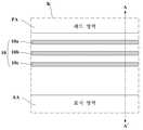
도 1은 종래 기술에 따른 OLED 표시 장치의 인캡슐레이션 방법을 나타낸 단면도이다.1 is a cross-sectional view illustrating a method of encapsulating an OLED display according to a related art.
도 1을 참조하면, 종래의 인캡슐레이션 방법은 유기 발광 소자(80)가 형성된 기판(70) 상에 제1 무기막(90a)과, 유기막(90b)과, 제2 무기막(90c)의 복수층으로 이루어진 인캡층(90)을 형성하여 봉지를 한다.1, a conventional encapsulation method includes a first
인캡층(90)을 구성하는 유기막(90b)은 폴리머(polymer) 재질로 구성되며, 액상 형태로 기판(70) 상에 도포된 후 경화 공정을 거쳐 형성된다. 이러한 유기막(90b)은 경화 공정 전까지 유동성을 갖기 때문에 유기막(90b)을 구성하는 액상 폴리머가 기판(70) 외곽에 형성된 패드부를 침범하는 문제점이 있다. 도 2는 액상 폴리머가 기판(70) 외곽에 형성된 구동 IC의 패드부를 침범하여 발생된 불량을 나타낸 사진이다. 도 2에 도시한 바와 같이, 액상 폴리머가 패드부를 침범하면 구동 불량이나 점등 검사 불량을 유발한다.The
본 발명은 상기와 같은 문제점을 해결하기 위한 것으로, 기판의 외곽에 댐을 형성하여 인캡층을 구성하는 유기막의 형성시 액상 폴리머가 패드 영역을 침범하는 것을 방지할 수 있는 OLED 표시 장치 및 그의 제조 방법을 제공하는데 목적이 있다.SUMMARY OF THE INVENTION The present invention has been made to solve the above problems and it is an object of the present invention to provide an OLED display device capable of preventing a liquid polymer from invading a pad region during formation of an organic film constituting a capping layer, And the like.
상기와 같은 목적을 달성하기 위해, 본 발명의 실시 예에 따른 OLED 표시 장치는 유기 발광 소자가 형성되는 표시 영역과, 상기 표시 영역의 외곽에 형성된 다수의 패드를 포함하는 패드 영역을 포함하는 기판과; 상기 유기 발광 소자를 덮으며 상기 기판 상에 형성된 인캡층과; 상기 표시 영역과 상기 패드 영역 사이에 형성되어 상기 인캡층을 구성하는 유기막 재질의 흐름을 제어하는 댐을 구비하는 것을 특징으로 한다.In order to accomplish the above object, an OLED display according to an exemplary embodiment of the present invention includes a substrate including a display region in which an organic light emitting diode is formed, and a pad region including a plurality of pads formed on the periphery of the display region, ; An encapsulation layer covering the organic light emitting device and formed on the substrate; And a dam formed between the display region and the pad region to control the flow of the organic film material constituting the encapsulation layer.
또한, 상기와 같은 목적을 달성하기 위해, 본 발명의 실시 예에 따른 OLED 표시 장치의 제조 방법은 기판 상의 표시 영역에 유기 발광 소자를 형성하는 단계와; 상기 표시 영역과 다수의 패드가 형성된 패드 영역 사이에 댐을 형성하는 단계와; 상기 유기 발광 소자를 덮으며 상기 기판 상에 인캡층을 형성하는 단계를 포함하고; 상기 댐은 상기 인캡층을 구성하는 유기막 재질의 흐름을 제어하는 것을 특징으로 한다.According to another aspect of the present invention, there is provided a method of manufacturing an OLED display, including: forming an organic light emitting diode in a display region on a substrate; Forming a dam between the display area and a pad area where a plurality of pads are formed; Forming an encapsulation layer on the substrate, the encapsulation layer covering the organic light emitting device; And the dam controls the flow of the organic film material constituting the encapsulation layer.
상기 댐은 상기 표시 영역의 외곽을 둘러싸도록 형성되고, 상기 다수의 패드가 형성된 상기 기판의 일측에서 특정 간격을 갖고 이격된 다수의 댐을 포함하는 것을 특징으로 한다.The dam may include a plurality of dams formed to surround an outer periphery of the display area and spaced apart at a predetermined distance from one side of the substrate on which the plurality of pads are formed.
상기 다수의 댐은 실선과, 점선과, 지그재그 중 선택된 어느 하나의 형태를 갖는 것을 특징으로 한다.The plurality of dams have a shape selected from a solid line, a dotted line, and a zigzag.
상기 다수의 댐 중 최외곽에 형성된 댐은 실선 형태로 형성되고, 나머지 댐들은 점선 형태로 형성되는 것을 특징으로 한다.The dams formed at the outermost of the plurality of dams are formed in a solid line shape, and the remaining dams are formed in a dotted line shape.
상기 다수의 댐 중 상기 표시 영역과 가장 인접한 댐은 상기 표시 영역과 상기 패드 영역 사이를 가로지르는 제1 방향으로 특정 간격씩 이격된 다수의 서브 댐을 포함하며, 상기 각 서브 댐은 길이 방향이 상기 제1 방향에 수직된 제2 방향으로 형성되는 것을 특징으로 한다.Wherein the dams closest to the display area of the plurality of dams include a plurality of sub dams spaced apart by a predetermined distance in a first direction across the display area and the pad area, And a second direction perpendicular to the first direction.
상기 댐은 상기 표시 영역에 형성된 뱅크 및 스페이서를 구성하는 물질과, 박막 트랜지스터를 구성하는 금속 물질들 중 선택된 적어도 하나와 동일한 재질로 형성되고, 상기 선택된 물질들이 적층되어 적어도 하나의 층을 갖는 것을 특징으로 한다.The dam is formed of the same material as at least one selected from the materials constituting the bank and the spacer formed in the display region and the metal materials constituting the thin film transistor, and the selected materials are stacked to have at least one layer .
본 발명은 기판(SUB)의 외곽에 댐(10)을 형성하여 인캡층(20)을 구성하는 유기막(24)의 형성시 액상 폴리머가 패드 영역(PA)을 침범하는 것을 방지한다. 그리고 본 발명은 댐(10)이 액상 폴리머의 유동성이 저하될 경우 흐름을 외곽 방향으로 유도하여 유기막의 두께 차이로 인한 얼룩 발생을 방지한다.The present invention forms a
도 1은 종래 기술에 따른 OLED 표시 장치의 인캡슐레이션 방법을 나타낸 단면도이다.
도 2는 액상 폴리머가 기판(70) 외곽에 형성된 구동 IC의 패드부를 침범하여 발생된 불량을 나타낸 사진이다.
도 3은 본 발명의 실시 예에 따른 OLED 표시 장치의 평면도이다.
도 4는 도 3에 도시된 표시 영역(AA)의 단면도이다.
도 5는 도 3에 도시된 'K' 영역의 확대도이다.
도 6은 도 5에 도시된 A-A' 선에 따른 단면도이다.
도 7은 도 5에 도시된 A-A' 선에 따른 단면도이다.
도 8a 및 도 8b는 본 발명의 다른 실시 예에 따른 댐(10)의 확대 평면도이다.
도 9는 본 발명의 또 다른 실시 예에 따른 댐(10)의 확대 평면도이다.
도 10은 도 9에 도시된 B-B' 선에 따른 단면도이다.1 is a cross-sectional view illustrating a method of encapsulating an OLED display according to a related art.
Fig. 2 is a photograph showing defects generated by the liquid polymer impinging on the pad portion of the driving IC formed outside the
3 is a plan view of an OLED display according to an embodiment of the present invention.
4 is a sectional view of the display area AA shown in Fig.
5 is an enlarged view of the 'K' region shown in FIG.
6 is a cross-sectional view taken along the line AA 'shown in FIG.
7 is a cross-sectional view taken along the line AA 'shown in FIG.
8A and 8B are enlarged plan views of a
9 is an enlarged plan view of a
10 is a sectional view taken along the line BB 'shown in FIG.
이하, 본 발명의 실시 예에 따른 OLED 표시 장치 및 그의 제조 방법을 첨부된 도면을 참조하여 상세히 설명한다.Hereinafter, an OLED display device and a method of manufacturing the same according to embodiments of the present invention will be described in detail with reference to the accompanying drawings.
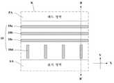
도 3은 본 발명의 실시 예에 따른 OLED 표시 장치의 평면도이다.3 is a plan view of an OLED display according to an embodiment of the present invention.
도 3을 참조하면, 본 발명의 OLED 표시 장치는 유기 발광 소자가 형성되는 표시 영역(AA)과, 다수의 패드(30, 도 7 참조)가 형성되는 패드 영역(PA)을 포함하는 기판(SUB)과, 표시 영역(AA)에 형성된 유기 발광 소자를 덮으며 기판(SUB) 상에 형성된 인캡층(20, 도 4 참조)과, 표시 영역(AA)과 패드 영역(PA) 사이에 형성되어 인캡층(20)을 구성하는 유기막(24) 재질의 흐름을 제어하는 댐(10)을 구비한다.3, the OLED display of the present invention includes a substrate SUB including a display area AA where an organic light emitting device is formed and a pad area PA where a plurality of pads 30 (see FIG. 7) ), An encapsulation layer 20 (see FIG. 4) formed on the substrate SUB, covering the organic light emitting element formed in the display area AA, and a
댐(10)은 인캡층(20)을 구성하는 유기막(24)의 제조시 유기막(24)을 구성하는 액상 폴리머가 패드 영역(PA)으로 침범하는 것을 막는 역할을 한다. 이를 위해, 댐(10)은 표시 영역(AA)과 패드 영역(PA) 사이에만 형성될 수 있으나, 바람직하게는 표시 영역(AA)의 외곽을 둘러싸도록 형성된다.The
댐(10)은 도 3에 도시한 바와 같이, 패드 영역(PA)이 형성된 기판(SUB)의 일측에서 여러겹으로 형성될 수 있다. 구체적으로, 댐(10)은 패드 영역(PA)이 형성된 기판(SUB)의 일측에서 특정 간격을 갖고 이격된 다수의 댐을 포함할 수 있다. 이에 따라, 댐(10)은 상기 액상 폴리머가 패드 영역(PA)으로 침범하는 것을 보다 쉽게 방지할 수 있다. 한편, 댐(10)은 패드 영역(PA)이 형성된 일측 외에 다른 측면에서도 여러겹으로 형성될 수 있다.The
이와 같이, 본 발명은 기판(SUB)의 외곽에 댐(10)을 형성하여 인캡층(20)을 구성하는 유기막(24)의 형성시 액상 폴리머가 패드 영역(PA)을 침범하는 것을 방지할 수 있다. 본 발명의 댐(10)에 대하여서는 보다 구체적으로 후술하기로 한다.As described above, according to the present invention, the
이하, 표시 영역(AA)에 형성된 유기 발광 소자를 구체적으로 설명한다.Hereinafter, the organic light emitting element formed in the display area AA will be specifically described.
도 4는 도 3에 도시된 표시 영역(AA)의 단면도이다.4 is a sectional view of the display area AA shown in Fig.
도 4를 참조하면, 표시 영역(AA)에 형성된 유기 발광 소자는 기판(SUB) 상에 형성된 박막 트랜지스터(이하, TFT)들(ST, DT)과, TFT들(ST, DT)에 연결되어 구동되는 OLED를 구비한다. 여기서, TFT들(ST, DT)은 스위칭 TFT(ST)와, 구동 TFT(DT)를 포함한다.4, the organic light emitting device formed in the display area AA includes thin film transistors (hereinafter referred to as TFTs) ST formed on a substrate SUB, Lt; / RTI > Here, the TFTs ST and DT include a switching TFT ST and a driving TFT DT.
스위칭 TFT(ST)는 게이트 라인(미도시)과 데이터 라인(미도시)이 교차부에 형성되어, 그들에 접속된다. 이러한 스위칭 TFT(ST)는 화소를 선택하는 기능을 한다. 이를 위해, 스위칭 TFT(ST)는 게이트 라인에서 분기된 게이트 전극(SG)과, 반도체 층(SA)과, 소스 전극(SS)과, 드레인 전극(SD)을 포함한다.The switching TFT ST is formed at the intersection of gate lines (not shown) and data lines (not shown), and is connected to them. This switching TFT ST functions to select a pixel. To this end, the switching TFT ST includes a gate electrode SG, a semiconductor layer SA, a source electrode SS and a drain electrode SD branched from the gate line.
구동 TFT(DT)는 스위칭 TFT(ST)에 의해 선택된 화소의 애노드 전극(ANO)을 구동하는 역할을 한다. 이를 위해, 구동 TFT(DT)는 스위칭 TFT(ST)의 드레인 전극(SD)과 연결된 게이트 전극(DG)과, 반도체 층(DA)과, 구동 전류 전송 배선(미도시)에 연결된 소스 전극(DS)과, 드레인 전극(DD)을 포함한다. 구동 TFT(DT)의 드레인 전극(DD)은 OLED의 애노드 전극(ANO)과 연결된다.The driving TFT DT serves to drive the anode electrode ANO of the pixel selected by the switching TFT ST. To this end, the driving TFT DT includes a gate electrode DG connected to the drain electrode SD of the switching TFT ST, a semiconductor layer DA, and a source electrode DS (not shown) connected to the driving current transmission wiring And a drain electrode DD. The drain electrode DD of the driving TFT DT is connected to the anode electrode ANO of the OLED.
도 4에서는 일례로, 탑 게이트(Top Gate) 구조의 TFT를 도시하였다. 이 경우, 스위칭 TFT(ST)의 반도체 층(SA)과 구동 TFT(DT)의 반도체 층(DA)들이 기판(SUB) 위에 먼저 형성되고, 반도체 층들(SA, DA) 상에 게이트 절연막(GI)이 형성된다. 그리고 게이트 절연막(GI) 상에 게이트 전극들(SG, DG)이 반도체 층들(SA, DA)의 중심부에 중첩되어 형성된다. 그리고 반도체 층들(SA, DA)의 양 측면에는 콘택홀을 통해 소스 전극들(SS, DS) 및 드레인 전극들(SD, DD)이 연결된다. 소스 전극(SS, DS) 및 드레인 전극(SD, DD)들은 게이트 전극들(SG, DG)을 덮는 층간 절연막(IN) 위에 형성된다.In Fig. 4, a TFT having a top gate structure is shown as an example. In this case, the semiconductor layer DA of the switching TFT ST and the semiconductor layer DA of the driving TFT DT are formed first on the substrate SUB, and the gate insulating film GI is formed on the semiconductor layers SA, . The gate electrodes SG and DG are formed on the gate insulating film GI in such a manner as to overlap the center portions of the semiconductor layers SA and DA. Source electrodes SS and DS and drain electrodes SD and DD are connected to both sides of the semiconductor layers SA and DA through a contact hole. The source electrodes SS and DS and the drain electrodes SD and DD are formed on the interlayer insulating film IN covering the gate electrodes SG and DG.
스위칭 TFT(ST)와 구동 TFT(DT)가 형성된 기판(SUB) 상에는 보호막(PAS)과, 평탄화 막(PL)이 도포된다. 평탄화 막(PL)을 포함한 기판(SUB) 상에는 발광 영역을 구획하는 뱅크(BA)가 형성된다. 그리고 뱅크(BA)들 중 일부는 상부에 스페이서(SP)가 더 형성된다.On the substrate SUB on which the switching TFT ST and the driving TFT DT are formed, the protective film PAS and the flattening film PL are coated. On the substrate SUB including the flattening film PL, a bank BA for partitioning the light emitting region is formed. Some of the banks BA further have a spacer SP formed thereon.
발광 영역에는 콘택홀을 통해 구동 TFT(DT)의 드레인 전극(DD)과 접촉하는 애노드 전극(ANO)이 형성된다. 애노드 전극(ANO) 상에는 유기 반도체층(OL)이 형성되며, 유기 반도체층(OL) 상에는 캐소드 전극(CAT)이 적층된다. 여기서, 유기 반도체층(OL)은 정공 주입층(hole injection layer)과, 정공 수송층(hole transport layer)과, 발광층(emission layer)과, 전자 수송층(electron transport layer)과, 전자 주입층(electron injection layer)을 포함한다.An anode electrode ANO in contact with the drain electrode DD of the driving TFT DT through the contact hole is formed in the light emitting region. An organic semiconductor layer OL is formed on the anode electrode ANO and a cathode electrode CAT is formed on the organic semiconductor layer OL. Here, the organic semiconductor layer OL includes a hole injection layer, a hole transport layer, an emission layer, an electron transport layer, an electron injection layer, layer.
이와 같은, 유기 발광 소자는 뱅크(BA) 및 스페이서(SP)를 포함한 기판(SUB) 상에 제1 무기막(22)과, 유기막(24)과, 제2 무기막(26)의 복수층으로 이루어진 인캡층(20)을 형성함으로써 봉지된다. 인캡층(20)은 상부에 접합층(미도시)이 개재됨으로써 봉지 기판(미도시)과 합착된다.The organic light emitting element has the first
인캡층(20)에 구비된 유기막(24)은 폴리머(polymer) 재질로 구성되며, 액상 형태로 기판(SUB) 상에 도포된 후 경화 공정을 거쳐 형성된다. 유기막(24)의 형성시 액상 형태를 갖는 폴리머는 도 3에 도시한 바와 같은 댐(10)에 의해 흐름이 제어됨으로써 패드 영역(PA)을 침범하지 않게 된다.The
도 5는 도 3에 도시된 'K' 영역의 확대도이다. 도 6은 도 5에 도시된 A-A' 선에 따른 단면도이다.5 is an enlarged view of the 'K' region shown in FIG. 6 is a cross-sectional view taken along the line A-A 'shown in FIG.
도 5 및 도 6을 참조하면, 패드 영역(PA)에는 다수의 패드(30)가 형성된다. 다수의 패드(30)는 회로 필름(미도시)과 접속되기 위한 패드이거나, 구동 IC와 접속되는 패드일 수 있다. 도 6에서는 패드(30)를 개략적으로 도시하였으나, 패드(30)의 구조는 본 발명의 출원인에 의해 고안된 대한민국 공개특허공보 제10-2013-0015113호 등에 개시된 설명으로 대신하기로 한다.Referring to FIGS. 5 and 6, a plurality of
한편, 패드(30)가 형성된 패드 영역(PA)과 유기 발광 소자가 형성된 표시 영역(AA) 사이의 중간 영역(MA)에는 여러겹으로 형성된 다수의 댐(10a, 10b, 10c)이 형성된다. 다수의 댐(10a, 10b, 10c)은 인캡층(20)의 유기막(24) 형성시 액상 형태를 갖는 폴리머가 패드 영역(PA)을 침범하는 것을 막는다.A plurality of
본 발명의 댐(10)은 표시 영역(AA)에 형성된 뱅크(BA) 및 스페이서(SP)를 구성하는 유기 물질로 형성될 수 있다. 이 경우, 댐(10)은 뱅크(BA) 또는 스페이서(SP)와 동일 공정에서 동시에 형성된다. 또한, 본 발명의 댐(10)은 TFT를 구성하는 금속 물질, 예를 들어 게이트 전극이나, 소스 및 드레인 전극과 동일한 재질로 형성될 수 있다. 이 경우, 댐(10)은 TFT 형성 공정에서 동시에 형성된다.The
이와 같이, 본 발명의 댐(10)은 뱅크(BA) 및 스페이서(SP)를 구성하는 유기 물질과, TFT를 구성하는 금속 물질 중 선택된 적어도 하나와 동일한 재질로 형성될 수 있다. 따라서, 본 발명은 댐(10)을 형성하기 위한 별도의 공정이나 장비가 필요없다.As described above, the
한편, 댐(10)은 도 7에 도시한 바와 같이, 상기에서 선택된 물질들이 적층된 다층 구조로 형성될 수 있다. 예를 들어, 댐(10)은 뱅크(BA) 형성 공정과, 스페이서(SP) 형성 공정 각각에서 물질이 적층된 이층 구조로 형성될 수 있다.Meanwhile, as shown in FIG. 7, the
이하, 본 발명의 댐(10)의 다양한 실시 예를 구체적으로 설명한다.Hereinafter, various embodiments of the
도 8a 및 도 8b는 본 발명의 다른 실시 예에 따른 댐(10)의 확대 평면도이다.8A and 8B are enlarged plan views of a
도 5에서 댐(10)은 실선 형태로 도시하였으나, 댐(10)은 다양하게 실시 변경이 가능하다. 구체적으로, 본 발명의 댐(10)은 실선과, 점선과, 지그재그 중 어느 하나의 형태를 가질 수 있다.Although the
도 8a에 도시한 바와 같이, 댐(10a, 10b, 10c)이 여러겹으로 형성될 경우, 다수의 댐(10a, 10b, 10c) 중에서 최외곽에 형성된 댐(10a)은 실선으로 형성되고, 나머지 댐들(10b, 10c)은 점선 형태로 형성될 수 있다.8A, when the
또한, 도 8b에 도시한 바와 같이, 다수의 댐(10a, 10b, 10c) 중에서 최외곽에 형성된 댐(10a)은 실선으로 형성되고, 나머지 댐들(10b, 10c)은 지그재그 형태 형성될 수 있다.8B, the
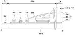
도 9는 본 발명의 또 다른 실시 예에 따른 댐(10)의 확대 평면도이다. 도 10은 도 9에 도시된 B-B' 선에 따른 단면도이다.9 is an enlarged plan view of a
도 9 및 도 10을 참조하면, 패드(30)가 형성된 패드 영역(PA)과 유기 발광 소자가 형성된 표시 영역(AA) 사이의 중간 영역(MA)에는 여러겹으로 형성된 다수의 댐(10a, 10b, 10c, 10d)이 형성된다.9 and 10, a plurality of
다수의 댐(10a, 10b, 10c, 10d) 중에서 상대적으로 외곽에 형성된 댐들(10a, 10b, 10c)은 표시 영역(AA)과 패드 영역(PA)을 가로 지르는 제1 방향(도 9에서 X 방향)으로 형성된다. 이들(10a, 10b, 10c)은 인캡층(20)의 유기막(24) 형성시 액상 형태를 갖는 폴리머가 패드 영역(PA)을 침범하는 것을 막는 역할을 한다.The
다수의 댐(10a, 10b, 10c, 10d) 중에서 표시 영역(AA)과 가장 인접한 댐(10d)은 제1 방향으로 특정 간격씩 이격된 다수의 서브 댐들을 포함하며, 각 서브 댐들은 길이 방향이 제1 방향에 수직된 제2 방향(도 9에서 Y 방향)으로 형성된다. 이 댐(10d)은 인캡층(20)의 유기막(24) 형성시 액상 형태를 갖는 폴리머가 도 10에서 점선으로 도시한 바와 같이, 유동성이 저하될 경우, 폴리머의 흐름을 기판(SUB)의 외곽 방향으로 유도하는 역할을 한다. 이에 따라, 본 발명은 인캡층(20)의 유기막(24)의 형성시 액상 폴리머의 유동성 저하로 인한 유기막(24)의 두께 차이와, 그로 인한 얼룩 발생을 방지할 수 있다.The
이와 같이, 본 발명은 기판(SUB)의 외곽에 댐(10)을 형성하여 인캡층(20)을 구성하는 유기막(24)의 형성시 액상 폴리머가 패드 영역(PA)을 침범하는 것을 방지한다. 그리고 댐(10)이 액상 폴리머의 유동성이 저하될 경우 흐름을 외곽 방향으로 유도하여 유기막의 두께 차이로 인한 얼룩 발생을 방지한다.As described above, according to the present invention, the
이상에서 설명한 본 발명은 상술한 실시 예 및 첨부된 도면에 한정되는 것이 아니고, 본 발명의 기술적 사상을 벗어나지 않는 범위 내에서 여러 가지 치환, 변형 및 변경이 가능하다는 것이 본 발명이 속하는 기술분야에서 통상의 지식을 가진 자에게 있어 명백할 것이다.It will be apparent to those skilled in the art that various modifications and variations can be made in the present invention without departing from the spirit or scope of the general inventive concept as defined by the appended claims and their equivalents. Will be clear to those who have knowledge of.
AA: 표시 영역 PA: 패드 영역
10: 댐 SUB: 기판
20: 인캡층AA: display area PA: pad area
10: dam SUB: substrate
20: encapsulation layer
Claims (12)
Translated fromKorean상기 유기 발광 소자를 덮으며 상기 기판 상에 형성된 인캡층과;
상기 표시 영역과 상기 패드 영역 사이에 형성되어 상기 인캡층을 구성하는 유기막 재질의 흐름을 제어하는 댐을 구비하는 것을 특징으로 하는 OLED 표시 장치.A substrate including a display region in which an organic light emitting element is formed, and a pad region including a plurality of pads formed in an outer portion of the display region;
An encapsulation layer covering the organic light emitting device and formed on the substrate;
And a dam formed between the display region and the pad region to control the flow of the organic film material constituting the encapsulation layer.
상기 댐은
상기 표시 영역의 외곽을 둘러싸도록 형성되고, 상기 다수의 패드가 형성된 상기 기판의 일측에서 특정 간격을 갖고 이격된 다수의 댐을 포함하는 것을 특징으로 하는 OLED 표시 장치.The method according to claim 1,
The dam
And a plurality of dams formed to surround an outer periphery of the display region and spaced apart at a predetermined distance from one side of the substrate on which the plurality of pads are formed.
상기 다수의 댐은
실선과, 점선과, 지그재그 중 선택된 어느 하나의 형태를 갖는 것을 특징으로 하는 OLED 표시 장치.The method of claim 2,
The plurality of dams
Wherein the OLED display has one of a solid line, a dotted line, and a zigzag.
상기 다수의 댐 중 최외곽에 형성된 댐은 실선 형태로 형성되고, 나머지 댐들은 점선 형태로 형성되는 것을 특징으로 하는 OLED 표시 장치.The method of claim 3,
Wherein the dams formed at the outermost of the plurality of dams are formed in a solid line shape, and the remaining dams are formed in a dotted line shape.
상기 다수의 댐 중 상기 표시 영역과 가장 인접한 댐은 상기 표시 영역과 상기 패드 영역 사이를 가로지르는 제1 방향으로 특정 간격씩 이격된 다수의 서브 댐을 포함하며, 상기 각 서브 댐은 길이 방향이 상기 제1 방향에 수직된 제2 방향으로 형성되는 것을 특징으로 하는 OLED 표시 장치.The method of claim 4,
Wherein the dams closest to the display area of the plurality of dams include a plurality of sub dams spaced apart by a predetermined distance in a first direction across the display area and the pad area, And a second direction perpendicular to the first direction.
상기 댐은
상기 표시 영역에 형성된 뱅크 및 스페이서를 구성하는 물질과, 박막 트랜지스터를 구성하는 금속 물질들 중 선택된 적어도 하나와 동일한 재질로 형성되고,
상기 선택된 물질들이 적층되어 적어도 하나의 층을 갖는 것을 특징으로 하는 OLED 표시 장치.The method according to claim 1,
The dam
A material constituting the bank and the spacer formed in the display region and at least one selected from the metal materials constituting the thin film transistor,
Wherein the selected materials are stacked to have at least one layer.
상기 표시 영역과 다수의 패드가 형성된 패드 영역 사이에 댐을 형성하는 단계와;
상기 유기 발광 소자를 덮으며 상기 기판 상에 인캡층을 형성하는 단계를 포함하고;
상기 댐은 상기 인캡층을 구성하는 유기막 재질의 흐름을 제어하는 것을 특징으로 하는 OLED 표시 장치의 제조 방법.Forming an organic light emitting element in a display region on a substrate;
Forming a dam between the display area and a pad area where a plurality of pads are formed;
Forming an encapsulation layer on the substrate, the encapsulation layer covering the organic light emitting device;
Wherein the dam controls a flow of an organic film material constituting the encapsulation layer.
상기 댐은
상기 표시 영역의 외곽을 둘러싸도록 형성되고, 상기 다수의 패드가 형성된 상기 기판의 일측에서 특정 간격을 갖고 이격된 다수의 댐을 포함하는 것을 특징으로 하는 OLED 표시 장치의 제조 방법.The method of claim 7,
The dam
And a plurality of dams formed to surround an outer periphery of the display region and spaced apart at a predetermined distance from one side of the substrate on which the plurality of pads are formed.
상기 다수의 댐은
실선과, 점선, 지그재그 중 선택된 어느 하나의 형태를 갖는 것을 특징으로 하는 OLED 표시 장치의 제조 방법.The method of claim 8,
The plurality of dams
Wherein the first electrode has a shape selected from a solid line, a dotted line, and a zigzag.
상기 다수의 댐 중 최외곽에 형성된 댐은 실선 형태로 형성되고, 나머지 댐들은 점선 형태로 형성되는 것을 특징으로 하는 OLED 표시 장치의 제조 방법.The method of claim 9,
Wherein the dams formed at the outermost of the plurality of dams are formed in a solid line shape and the remaining dams are formed in a dotted line shape.
상기 다수의 댐 중 상기 표시 영역과 가장 인접한 댐은 상기 표시 영역과 상기 패드 영역 사이를 가로지르는 제1 방향으로 특정 간격씩 이격된 다수의 서브 댐을 포함하며, 상기 각 서브 댐은 길이 방향이 상기 제1 방향에 수직된 제2 방향으로 형성되는 것을 특징으로 하는 OLED 표시 장치의 제조 방법.The method of claim 10,
Wherein the dams closest to the display area of the plurality of dams include a plurality of sub dams spaced apart by a predetermined distance in a first direction across the display area and the pad area, And the second direction is perpendicular to the first direction.
상기 댐은
상기 표시 영역에 형성된 뱅크와, 스페이서와, 무기 절연막과, 유기 절연막과, 박막 트랜지스터를 구성하는 금속 물질들 중 선택된 적어도 하나와 동일한 재질로 형성되고,
상기 선택된 물질들이 적층되어 적어도 하나의 층을 갖는 것을 특징으로 하는 OLED 표시 장치의 제조 방법.The method of claim 7,
The dam
A spacer, an inorganic insulating film, an organic insulating film, and at least one selected from metal materials constituting the thin film transistor, the bank being formed in the display region,
Wherein the selected materials are stacked to have at least one layer.
Priority Applications (5)
| Application Number | Priority Date | Filing Date | Title |
|---|---|---|---|
| KR20130104250AKR20150025994A (en) | 2013-08-30 | 2013-08-30 | Organic light emitting diode display device and method of fabricating the same |
| CN201410367430.7ACN104425760B (en) | 2013-08-30 | 2014-07-29 | Organic LED display device and its manufacture method |
| US14/449,228US9391296B2 (en) | 2013-08-30 | 2014-08-01 | Organic light emitting diode display device having a dam for controlling flow of encapsulant |
| US15/174,058US11653521B2 (en) | 2013-08-30 | 2016-06-06 | Organic light emitting diode display device having a dam for controlling flow of encapsulant |
| US15/833,308US10964909B2 (en) | 2013-08-30 | 2017-12-06 | Organic light emitting diode display device having a dam for controlling flow of encapsulant |
Applications Claiming Priority (1)
| Application Number | Priority Date | Filing Date | Title |
|---|---|---|---|
| KR20130104250AKR20150025994A (en) | 2013-08-30 | 2013-08-30 | Organic light emitting diode display device and method of fabricating the same |
Publications (1)
| Publication Number | Publication Date |
|---|---|
| KR20150025994Atrue KR20150025994A (en) | 2015-03-11 |
Family
ID=52581875
Family Applications (1)
| Application Number | Title | Priority Date | Filing Date |
|---|---|---|---|
| KR20130104250ACeasedKR20150025994A (en) | 2013-08-30 | 2013-08-30 | Organic light emitting diode display device and method of fabricating the same |
Country Status (3)
| Country | Link |
|---|---|
| US (3) | US9391296B2 (en) |
| KR (1) | KR20150025994A (en) |
| CN (1) | CN104425760B (en) |
Cited By (28)
| Publication number | Priority date | Publication date | Assignee | Title |
|---|---|---|---|---|
| KR20160129776A (en)* | 2015-04-30 | 2016-11-09 | 에버디스플레이 옵트로닉스 (상하이) 리미티드 | Display module encapsulating structure and preparation method thereof |
| KR20170002148A (en)* | 2015-06-29 | 2017-01-06 | 엘지디스플레이 주식회사 | Organic light emitting diode display and manufacturing method of the same |
| KR20170057911A (en)* | 2015-11-17 | 2017-05-26 | 삼성디스플레이 주식회사 | Display device and method of manufacturing display device |
| KR20170062856A (en)* | 2015-11-30 | 2017-06-08 | 엘지디스플레이 주식회사 | Organic light emitting display |
| KR20170142232A (en)* | 2016-06-16 | 2017-12-28 | 삼성디스플레이 주식회사 | Display device |
| KR20180011924A (en)* | 2016-07-25 | 2018-02-05 | 삼성디스플레이 주식회사 | Display device |
| KR20180039801A (en)* | 2016-10-10 | 2018-04-19 | 삼성디스플레이 주식회사 | Display apparatus |
| US10128463B2 (en) | 2016-02-19 | 2018-11-13 | Japan Display Inc. | Display device |
| KR20190003184A (en)* | 2017-06-30 | 2019-01-09 | 엘지디스플레이 주식회사 | Display device |
| KR20190031397A (en)* | 2017-09-15 | 2019-03-26 | 삼성디스플레이 주식회사 | Display device |
| US10319797B2 (en) | 2016-05-26 | 2019-06-11 | Samsung Display Co., Ltd. | Organic light-emitting display device and method of manufacturing the same |
| KR20190077870A (en)* | 2017-12-26 | 2019-07-04 | 엘지디스플레이 주식회사 | Display device |
| US10361254B2 (en) | 2016-07-29 | 2019-07-23 | Samsung Display Co., Ltd. | Display device including a touch sensing unit and method of manufacturing the same |
| US10474263B2 (en) | 2016-01-12 | 2019-11-12 | Samsung Display Co., Ltd. | Display device and method of manufacturing the same |
| US10564746B2 (en) | 2016-01-12 | 2020-02-18 | Samsung Display Co., Ltd. | Display device and method of manufacturing the same |
| US10629845B2 (en) | 2018-03-16 | 2020-04-21 | Samsung Display Co., Ltd. | Display device including a barrier layer |
| US10734459B2 (en) | 2018-03-08 | 2020-08-04 | Samsung Display Co., Ltd. | Display device |
| US10748971B2 (en) | 2016-07-29 | 2020-08-18 | Samsung Display Co., Ltd. | Display apparatus |
| US10777771B2 (en) | 2018-12-10 | 2020-09-15 | Samsung Display Co., Ltd. | Display apparatus |
| US10916603B2 (en) | 2017-12-21 | 2021-02-09 | Samsung Display Co., Ltd. | Display device and fabrication method thereof |
| US11088349B2 (en) | 2018-10-24 | 2021-08-10 | Samsung Display Co., Ltd. | Display module |
| US11088232B2 (en) | 2018-09-06 | 2021-08-10 | Samsung Display Co., Ltd. | Display device |
| KR20210107218A (en)* | 2020-02-21 | 2021-09-01 | 삼성디스플레이 주식회사 | Display apparatus and flexible display apparatus |
| KR20220042075A (en)* | 2015-05-12 | 2022-04-04 | 삼성디스플레이 주식회사 | organic light-emitting display |
| US11489025B2 (en) | 2016-07-29 | 2022-11-01 | Samsung Display Co., Ltd. | Touch sensing unit integrated display device including outgassing holes |
| US11825709B2 (en) | 2020-08-11 | 2023-11-21 | Samsung Display Co., Ltd. | Display device |
| US11900869B2 (en) | 2021-12-31 | 2024-02-13 | Samsung Display Co., Ltd. | Display device |
| US12089432B2 (en) | 2021-08-18 | 2024-09-10 | Samsung Display Co., Ltd. | Display device |
Families Citing this family (74)
| Publication number | Priority date | Publication date | Assignee | Title |
|---|---|---|---|---|
| KR101942850B1 (en)* | 2013-02-27 | 2019-04-17 | 엘지디스플레이 주식회사 | Liquid crystal display and method of fabricating the same |
| CN104241550B (en)* | 2014-08-05 | 2017-08-15 | 京东方科技集团股份有限公司 | OLED display and its method for packing |
| KR102377531B1 (en)* | 2015-01-23 | 2022-03-22 | 삼성디스플레이 주식회사 | Organic light emitting display device and manufacturing method thereof |
| US10319941B2 (en)* | 2015-02-16 | 2019-06-11 | Sharp Kabushiki Kaisha | Electroluminescence device |
| KR20160110597A (en)* | 2015-03-09 | 2016-09-22 | 삼성디스플레이 주식회사 | Organic light emitting diode device and manufacturing method thereof |
| KR102323242B1 (en)* | 2015-03-10 | 2021-11-08 | 삼성디스플레이 주식회사 | Flexible display device |
| KR102477299B1 (en) | 2015-06-12 | 2022-12-14 | 삼성디스플레이 주식회사 | Display device |
| KR102430819B1 (en)* | 2015-08-19 | 2022-08-10 | 삼성디스플레이 주식회사 | Organic light emitting display apparatus and method for manufacturing the same |
| CN105261712B (en)* | 2015-08-31 | 2017-07-25 | 上海和辉光电有限公司 | A kind of flexible OLED display panel |
| KR102427249B1 (en)* | 2015-10-16 | 2022-08-01 | 삼성디스플레이 주식회사 | display device |
| KR102329978B1 (en) | 2015-10-28 | 2021-11-22 | 엘지디스플레이 주식회사 | Flexible organic light emitting diode display device |
| CN105609532B (en)* | 2015-12-21 | 2019-11-22 | 上海天马有机发光显示技术有限公司 | Array substrate, manufacturing method thereof, and display panel |
| KR102466959B1 (en)* | 2015-12-31 | 2022-11-11 | 엘지디스플레이 주식회사 | Organic Light Emitting Display Device |
| CN105467687B (en)* | 2016-01-08 | 2018-06-22 | 深圳市华星光电技术有限公司 | Liquid crystal display and its manufacturing method |
| CN105489786B (en)* | 2016-02-29 | 2018-01-02 | 上海天马有机发光显示技术有限公司 | Encapsulating structure and method for packing, the display panel of array base palte |
| KR101834792B1 (en) | 2016-08-31 | 2018-03-06 | 엘지디스플레이 주식회사 | Organic light emitting display with touch sensor and fabricating method thereof |
| KR102553910B1 (en) | 2016-08-31 | 2023-07-07 | 엘지디스플레이 주식회사 | Display device and testing method thereof |
| KR101974086B1 (en)* | 2016-09-30 | 2019-05-02 | 삼성디스플레이 주식회사 | Display module |
| CN109845406A (en)* | 2016-10-03 | 2019-06-04 | 夏普株式会社 | The manufacturing method of organic EL display device and organic EL display device |
| KR102799673B1 (en) | 2016-11-29 | 2025-04-22 | 엘지디스플레이 주식회사 | Organic light emitting display device |
| KR20180061866A (en)* | 2016-11-30 | 2018-06-08 | 엘지디스플레이 주식회사 | Encapsulation unit and organic light emitting display including the same |
| KR20180076689A (en)* | 2016-12-28 | 2018-07-06 | 엘지디스플레이 주식회사 | Display device |
| JP2018113104A (en)* | 2017-01-06 | 2018-07-19 | 株式会社ジャパンディスプレイ | Display device and manufacturing method of display device |
| CN206479739U (en)* | 2017-03-03 | 2017-09-08 | 京东方科技集团股份有限公司 | A kind of display panel and display device |
| US10608062B2 (en) | 2017-03-16 | 2020-03-31 | Sharp Kabushiki Kaisha | Display device |
| JP6767296B2 (en)* | 2017-03-29 | 2020-10-14 | 京セラ株式会社 | Thermal head and thermal printer |
| US10559772B2 (en) | 2017-03-31 | 2020-02-11 | Sharp Kabushiki Kaisha | Display device and production method thereof |
| KR102438255B1 (en)* | 2017-05-31 | 2022-08-30 | 엘지디스플레이 주식회사 | Display device |
| CN206774584U (en)* | 2017-06-06 | 2017-12-19 | 京东方科技集团股份有限公司 | Thin-film packing structure and display device |
| JP2019003819A (en)* | 2017-06-14 | 2019-01-10 | 株式会社Joled | Organic EL display panel |
| KR102387631B1 (en)* | 2017-06-30 | 2022-04-15 | 엘지디스플레이 주식회사 | Display device with integrated touch screen and method for fabricating the same |
| CN107146858B (en) | 2017-07-12 | 2019-02-26 | 京东方科技集团股份有限公司 | Organic light-emitting component, preparation method thereof, and display device |
| KR102392707B1 (en)* | 2017-08-18 | 2022-04-29 | 엘지디스플레이 주식회사 | Organic Light Emitting Display Device |
| WO2019038884A1 (en)* | 2017-08-24 | 2019-02-28 | シャープ株式会社 | Display device |
| CN109427996A (en) | 2017-08-31 | 2019-03-05 | 昆山国显光电有限公司 | A kind of flexible display apparatus and preparation method |
| KR102449984B1 (en)* | 2017-10-31 | 2022-10-05 | 엘지디스플레이 주식회사 | Display device with touch sensor and manufacturing method for the same |
| KR102092034B1 (en)* | 2017-12-06 | 2020-03-23 | 엘지디스플레이 주식회사 | Display device and method of manufacturing the same |
| CN109904336B (en)* | 2017-12-07 | 2020-06-30 | 京东方科技集团股份有限公司 | Electronic device substrate and manufacturing method/display device |
| JP6378854B1 (en)* | 2017-12-26 | 2018-08-22 | 堺ディスプレイプロダクト株式会社 | Organic EL device and manufacturing method thereof |
| CN111937491A (en)* | 2018-03-28 | 2020-11-13 | 夏普株式会社 | Display device |
| CN111937494B (en)* | 2018-03-30 | 2023-06-16 | 夏普株式会社 | Display device and method for manufacturing display device |
| CN108565353B (en)* | 2018-04-20 | 2020-03-06 | 京东方科技集团股份有限公司 | Display backplane and display device |
| CN108832022B (en)* | 2018-06-28 | 2020-11-27 | 京东方科技集团股份有限公司 | OLED display panel and display device |
| JP7150527B2 (en)* | 2018-08-31 | 2022-10-11 | 株式会社ジャパンディスプレイ | Display device and display device manufacturing method |
| CN208904069U (en)* | 2018-11-07 | 2019-05-24 | 京东方科技集团股份有限公司 | A display substrate and a display device |
| US11296156B2 (en)* | 2018-11-28 | 2022-04-05 | Lg Display Co., Ltd. | Organic light emitting diode device |
| CN109545758B (en)* | 2018-12-12 | 2021-09-10 | 云谷(固安)科技有限公司 | Display device, display panel and preparation method thereof |
| KR102670355B1 (en)* | 2018-12-28 | 2024-05-28 | 엘지디스플레이 주식회사 | Display device with integrated touch screen |
| CN109728194B (en)* | 2018-12-28 | 2021-04-02 | 上海天马微电子有限公司 | Display panel and display device |
| CN109585690B (en)* | 2018-12-29 | 2021-03-16 | 厦门天马微电子有限公司 | Display panel and display device |
| CN110061148A (en)* | 2019-04-26 | 2019-07-26 | 武汉华星光电半导体显示技术有限公司 | Display panel and its packaging method, display device |
| CN110120462B (en)* | 2019-05-07 | 2020-09-01 | 武汉华星光电半导体显示技术有限公司 | A display panel, display module and electronic device |
| CN110379933B (en)* | 2019-05-30 | 2021-12-10 | 京东方科技集团股份有限公司 | Display substrate and preparation process thereof |
| CN110211998B (en)* | 2019-05-31 | 2022-01-18 | 武汉天马微电子有限公司 | Organic light-emitting display panel and display device |
| KR20210052782A (en) | 2019-10-31 | 2021-05-11 | 삼성디스플레이 주식회사 | Display panel |
| CN110752250B (en)* | 2019-11-25 | 2021-08-17 | 昆山国显光电有限公司 | a display panel |
| KR102866118B1 (en)* | 2019-11-28 | 2025-09-30 | 엘지디스플레이 주식회사 | Touch display device |
| KR102762377B1 (en)* | 2019-12-04 | 2025-02-04 | 삼성디스플레이 주식회사 | Display device |
| JP7465652B2 (en) | 2019-12-05 | 2024-04-11 | JDI Design and Development 合同会社 | Self-luminous display panel and method for manufacturing same |
| CN110931536A (en)* | 2019-12-12 | 2020-03-27 | 武汉天马微电子有限公司 | Organic light-emitting display panel and display device |
| KR20210079898A (en)* | 2019-12-20 | 2021-06-30 | 엘지디스플레이 주식회사 | Display device |
| CN111416063B (en)* | 2020-04-29 | 2022-05-31 | 武汉华星光电半导体显示技术有限公司 | Flexible OLED display panel and preparation method thereof |
| KR20220005675A (en)* | 2020-07-06 | 2022-01-14 | 삼성디스플레이 주식회사 | Display panel and mask sheet for manufacturing the same |
| US11600800B2 (en)* | 2020-07-31 | 2023-03-07 | Innolux Corporation | Electronic device having a curved profile interface corresponding to a recess |
| KR20220062182A (en)* | 2020-11-06 | 2022-05-16 | 삼성디스플레이 주식회사 | Display Panel, Display Device, and Method of Manufacturing of the Display Device |
| KR102798758B1 (en) | 2020-11-20 | 2025-04-23 | 삼성디스플레이 주식회사 | Display device and method of manufacturing the same |
| CN113097418B (en)* | 2021-03-30 | 2023-02-14 | 京东方科技集团股份有限公司 | Display panel, manufacturing method of display panel and display device |
| CN113178536B (en)* | 2021-04-23 | 2023-03-28 | 京东方科技集团股份有限公司 | Display substrate and display device |
| KR20230026597A (en)* | 2021-08-17 | 2023-02-27 | 삼성디스플레이 주식회사 | Electronic device and electronic device manufacturing method |
| KR20230100397A (en)* | 2021-12-28 | 2023-07-05 | 엘지디스플레이 주식회사 | Display device |
| JP2023132064A (en)* | 2022-03-10 | 2023-09-22 | 株式会社ジャパンディスプレイ | Display and method of manufacturing display |
| JP7743338B2 (en)* | 2022-03-17 | 2025-09-24 | 株式会社Magnolia White | Display device manufacturing method |
| CN114863814B (en)* | 2022-04-28 | 2024-04-16 | 昆山国显光电有限公司 | Display panel, manufacturing method of display panel and display device |
| CN115275052B (en)* | 2022-07-26 | 2023-09-26 | 武汉华星光电半导体显示技术有限公司 | Display panel and display device |
Family Cites Families (20)
| Publication number | Priority date | Publication date | Assignee | Title |
|---|---|---|---|---|
| JP3098515B1 (en)* | 1999-08-13 | 2000-10-16 | インターナショナル・ビジネス・マシーンズ・コーポレ−ション | Liquid crystal display device, liquid crystal display device with narrow frame, and method of manufacturing liquid crystal display device |
| US6698077B2 (en)* | 2000-12-27 | 2004-03-02 | International Business Machines Corporation | Display fabrication using modular active devices |
| US7109653B2 (en)* | 2002-01-15 | 2006-09-19 | Seiko Epson Corporation | Sealing structure with barrier membrane for electronic element, display device, electronic apparatus, and fabrication method for electronic element |
| JP4369211B2 (en)* | 2003-11-28 | 2009-11-18 | オプトレックス株式会社 | Manufacturing method of organic EL display |
| US7279063B2 (en)* | 2004-01-16 | 2007-10-09 | Eastman Kodak Company | Method of making an OLED display device with enhanced optical and mechanical properties |
| US8471278B2 (en)* | 2004-12-27 | 2013-06-25 | Otb Group B.V. | Method for manufacturing an OLED or a blank for forming an OLED as well as such a blank or OLED |
| US8304982B2 (en)* | 2006-11-30 | 2012-11-06 | Lg Display Co., Ltd. | Organic EL device and method for manufacturing the same |
| JP4438006B2 (en)* | 2007-03-30 | 2010-03-24 | Okiセミコンダクタ株式会社 | Semiconductor device and manufacturing method of semiconductor device |
| US7936122B2 (en)* | 2007-12-14 | 2011-05-03 | Canon Kabushiki Kaisha | Organic EL display apparatus |
| CN101971701A (en)* | 2008-07-10 | 2011-02-09 | 富士电机控股株式会社 | Organic el display and method for manufacturing same |
| KR101281868B1 (en)* | 2008-12-23 | 2013-07-03 | 엘지디스플레이 주식회사 | Electrophoretic Display Device and Method for manufacturing the same |
| JP5409315B2 (en)* | 2009-12-11 | 2014-02-05 | キヤノン株式会社 | Display device |
| JP2012003989A (en)* | 2010-06-17 | 2012-01-05 | Hitachi Displays Ltd | Method of manufacturing organic electroluminescent panel |
| KR101430173B1 (en)* | 2010-10-19 | 2014-08-13 | 삼성디스플레이 주식회사 | Organic light emitting diode display |
| KR101255537B1 (en)* | 2010-11-26 | 2013-04-16 | 삼성디스플레이 주식회사 | Flat display device and the manufacturing method thereof |
| KR101802523B1 (en) | 2011-08-02 | 2017-11-28 | 엘지디스플레이 주식회사 | Organic light emitting display device and manufacturing method of the same |
| JP5974415B2 (en)* | 2011-10-05 | 2016-08-23 | 株式会社ジャパンディスプレイ | Liquid crystal display |
| KR101923176B1 (en)* | 2012-06-11 | 2018-11-29 | 삼성디스플레이 주식회사 | Flat panel display device and manufacturing method thereof |
| KR102103421B1 (en)* | 2013-02-07 | 2020-04-23 | 삼성디스플레이 주식회사 | Organic light emitting diode device and manufacturing method thereof |
| KR102218573B1 (en)* | 2013-09-30 | 2021-02-23 | 삼성디스플레이 주식회사 | Display devices and methods of manufacturing display devices |
- 2013
- 2013-08-30KRKR20130104250Apatent/KR20150025994A/ennot_activeCeased
- 2014
- 2014-07-29CNCN201410367430.7Apatent/CN104425760B/enactiveActive
- 2014-08-01USUS14/449,228patent/US9391296B2/enactiveActive
- 2016
- 2016-06-06USUS15/174,058patent/US11653521B2/enactiveActive
- 2017
- 2017-12-06USUS15/833,308patent/US10964909B2/enactiveActive
Cited By (56)
| Publication number | Priority date | Publication date | Assignee | Title |
|---|---|---|---|---|
| KR20160129776A (en)* | 2015-04-30 | 2016-11-09 | 에버디스플레이 옵트로닉스 (상하이) 리미티드 | Display module encapsulating structure and preparation method thereof |
| KR20160129777A (en)* | 2015-04-30 | 2016-11-09 | 에버디스플레이 옵트로닉스 (상하이) 리미티드 | Encapsulation structure of display unit and method of forming the same |
| KR20160129778A (en)* | 2015-04-30 | 2016-11-09 | 에버디스플레이 옵트로닉스 (상하이) 리미티드 | Display module encapsulation structure and preparation method thereof |
| KR20220042075A (en)* | 2015-05-12 | 2022-04-04 | 삼성디스플레이 주식회사 | organic light-emitting display |
| KR20240013889A (en)* | 2015-06-29 | 2024-01-30 | 엘지디스플레이 주식회사 | Organic light emitting diode display and manufacturing method of the same |
| KR20230023699A (en)* | 2015-06-29 | 2023-02-17 | 엘지디스플레이 주식회사 | Organic light emitting diode display and manufacturing method of the same |
| KR20170002148A (en)* | 2015-06-29 | 2017-01-06 | 엘지디스플레이 주식회사 | Organic light emitting diode display and manufacturing method of the same |
| KR20170057911A (en)* | 2015-11-17 | 2017-05-26 | 삼성디스플레이 주식회사 | Display device and method of manufacturing display device |
| US11974453B2 (en) | 2015-11-17 | 2024-04-30 | Samsung Display Co., Ltd. | Display device with block members having different heights |
| US12372823B2 (en) | 2015-11-17 | 2025-07-29 | Samsung Display Co., Ltd. | Display device with block members |
| KR20170062856A (en)* | 2015-11-30 | 2017-06-08 | 엘지디스플레이 주식회사 | Organic light emitting display |
| US10474263B2 (en) | 2016-01-12 | 2019-11-12 | Samsung Display Co., Ltd. | Display device and method of manufacturing the same |
| US10564746B2 (en) | 2016-01-12 | 2020-02-18 | Samsung Display Co., Ltd. | Display device and method of manufacturing the same |
| US10128463B2 (en) | 2016-02-19 | 2018-11-13 | Japan Display Inc. | Display device |
| US10636854B2 (en) | 2016-05-26 | 2020-04-28 | Samsung Display Co., Ltd. | Organic light-emitting display device and method of manufacturing the same |
| US10903292B2 (en) | 2016-05-26 | 2021-01-26 | Samsung Display Co., Ltd. | Organic light-emitting display device and method of manufacturing the same |
| US10319797B2 (en) | 2016-05-26 | 2019-06-11 | Samsung Display Co., Ltd. | Organic light-emitting display device and method of manufacturing the same |
| US11659737B2 (en) | 2016-05-26 | 2023-05-23 | Samsung Display Co., Ltd. | Organic light-emitting display device and method of manufacturing the same |
| KR20170142232A (en)* | 2016-06-16 | 2017-12-28 | 삼성디스플레이 주식회사 | Display device |
| US9947898B2 (en) | 2016-06-16 | 2018-04-17 | Samsung Display Co., Ltd. | Display device having improved environmental tolerance |
| KR20180011924A (en)* | 2016-07-25 | 2018-02-05 | 삼성디스플레이 주식회사 | Display device |
| US11864407B2 (en) | 2016-07-25 | 2024-01-02 | Samsung Display Co., Ltd. | Display device with structure for preventing organic material overflow |
| KR20240078414A (en)* | 2016-07-25 | 2024-06-03 | 삼성디스플레이 주식회사 | Display device |
| US12150365B2 (en) | 2016-07-29 | 2024-11-19 | Samsung Display Co., Ltd. | Display apparatus |
| US10748971B2 (en) | 2016-07-29 | 2020-08-18 | Samsung Display Co., Ltd. | Display apparatus |
| US12295236B2 (en) | 2016-07-29 | 2025-05-06 | Samsung Display Co., Ltd. | Display device including capping pattern and method of manufacturing the same |
| US11974488B2 (en) | 2016-07-29 | 2024-04-30 | Samsung Display Co., Ltd. | Touch sensing unit integrated display device including outgassing holes |
| US12225802B2 (en) | 2016-07-29 | 2025-02-11 | Samsung Display Co., Ltd. | Touch sensing unit integrated display device including outgassing holes |
| US12213368B2 (en) | 2016-07-29 | 2025-01-28 | Samsung Display Co., Ltd. | Touch sensing unit integrated display device including outgassing holes |
| US10361254B2 (en) | 2016-07-29 | 2019-07-23 | Samsung Display Co., Ltd. | Display device including a touch sensing unit and method of manufacturing the same |
| US11910689B2 (en) | 2016-07-29 | 2024-02-20 | Samsung Display Co., Ltd. | Display device including capping pattern and method of manufacturing the same |
| US11527583B2 (en) | 2016-07-29 | 2022-12-13 | Samsung Display Co., Ltd. | Display device including capping pattern and method of manufacturing the same |
| US10804338B2 (en) | 2016-07-29 | 2020-10-13 | Samsung Display Co., Ltd. | Display device having a portion of a sub layer that does not overlap with signal lines |
| US11489025B2 (en) | 2016-07-29 | 2022-11-01 | Samsung Display Co., Ltd. | Touch sensing unit integrated display device including outgassing holes |
| US11502140B2 (en) | 2016-07-29 | 2022-11-15 | Samsung Display Co., Ltd. | Display apparatus |
| KR20180039801A (en)* | 2016-10-10 | 2018-04-19 | 삼성디스플레이 주식회사 | Display apparatus |
| US10446793B2 (en) | 2016-10-10 | 2019-10-15 | Samsung Display Co., Ltd. | Display apparatus |
| KR20190003184A (en)* | 2017-06-30 | 2019-01-09 | 엘지디스플레이 주식회사 | Display device |
| KR20190031397A (en)* | 2017-09-15 | 2019-03-26 | 삼성디스플레이 주식회사 | Display device |
| US10916603B2 (en) | 2017-12-21 | 2021-02-09 | Samsung Display Co., Ltd. | Display device and fabrication method thereof |
| KR20190077870A (en)* | 2017-12-26 | 2019-07-04 | 엘지디스플레이 주식회사 | Display device |
| US10734459B2 (en) | 2018-03-08 | 2020-08-04 | Samsung Display Co., Ltd. | Display device |
| US11133362B2 (en) | 2018-03-08 | 2021-09-28 | Samsung Display Co., Ltd. | Display device |
| US11882722B2 (en) | 2018-03-16 | 2024-01-23 | Samsung Display Co., Ltd. | Display device including a barrier layer with a concavo-convex side surface |
| US11349097B2 (en) | 2018-03-16 | 2022-05-31 | Samsung Display Co., Ltd. | Display device including a barrier layer with a concavo-convex side surface |
| US10629845B2 (en) | 2018-03-16 | 2020-04-21 | Samsung Display Co., Ltd. | Display device including a barrier layer |
| US11088232B2 (en) | 2018-09-06 | 2021-08-10 | Samsung Display Co., Ltd. | Display device |
| US11088349B2 (en) | 2018-10-24 | 2021-08-10 | Samsung Display Co., Ltd. | Display module |
| US10777771B2 (en) | 2018-12-10 | 2020-09-15 | Samsung Display Co., Ltd. | Display apparatus |
| US11758772B2 (en) | 2020-02-21 | 2023-09-12 | Samsung Display Co., Ltd. | Display apparatus including dams and monitoring bank |
| US12082452B2 (en) | 2020-02-21 | 2024-09-03 | Samsung Display Co., Ltd. | Flexible display apparatus including monitoring and buffering banks |
| KR20210107218A (en)* | 2020-02-21 | 2021-09-01 | 삼성디스플레이 주식회사 | Display apparatus and flexible display apparatus |
| US11825709B2 (en) | 2020-08-11 | 2023-11-21 | Samsung Display Co., Ltd. | Display device |
| US12185601B2 (en) | 2020-08-11 | 2024-12-31 | Samsung Display Co., Ltd. | Display device |
| US12089432B2 (en) | 2021-08-18 | 2024-09-10 | Samsung Display Co., Ltd. | Display device |
| US11900869B2 (en) | 2021-12-31 | 2024-02-13 | Samsung Display Co., Ltd. | Display device |
Also Published As
| Publication number | Publication date |
|---|---|
| US10964909B2 (en) | 2021-03-30 |
| CN104425760B (en) | 2017-06-30 |
| CN104425760A (en) | 2015-03-18 |
| US20180097200A1 (en) | 2018-04-05 |
| US20150060806A1 (en) | 2015-03-05 |
| US9391296B2 (en) | 2016-07-12 |
| US11653521B2 (en) | 2023-05-16 |
| US20160285045A1 (en) | 2016-09-29 |
Similar Documents
| Publication | Publication Date | Title |
|---|---|---|
| KR20150025994A (en) | Organic light emitting diode display device and method of fabricating the same | |
| US12178067B2 (en) | Display device | |
| KR102724703B1 (en) | Display apparatus and Mask for manufacturing display apparatus | |
| CN109638054B (en) | Display panel and manufacturing method | |
| CN103794736B (en) | Flexible organic electro-luminescence device | |
| CN104347673B (en) | Organic light emitting display device and manufacturing method thereof | |
| CN103824965B (en) | Organic LED display panel and manufacture method thereof | |
| US12133420B2 (en) | Display device and manufacturing method thereof | |
| US8581273B2 (en) | Organic EL device | |
| KR102178471B1 (en) | Large Area Transparent Organic Light Emitting Diode Display | |
| US10008694B2 (en) | Organic electroluminescent display device | |
| KR20140055606A (en) | Flexible organic electroluminescent device and method for fabricating the same | |
| KR20140033769A (en) | Organic electro luminescence device and method for fabricating the same | |
| JP2018005160A (en) | Display device | |
| JP6474337B2 (en) | Display device and manufacturing method thereof | |
| CN112420954B (en) | Display panel and manufacturing method thereof | |
| KR102542133B1 (en) | Display device for preventing corrosion | |
| KR20110071646A (en) | Organic light emitting diode display and manufacturing method | |
| KR102247825B1 (en) | Bottom Emission Type Organic Light Emission Diode Display Having Color Filters And Method For Manufacturing The Same | |
| KR101950837B1 (en) | Organic electro luminescence device and method for fabricating the same | |
| US20220102449A1 (en) | Organic light emitting display device | |
| KR20150042604A (en) | Organic light emitting diode display | |
| JP4664877B2 (en) | Organic electroluminescence display device | |
| KR20250081202A (en) | Display Device | |
| KR20070068227A (en) | Method for manufacturing electroluminescent display device and electroluminescent display device manufactured thereby |
Legal Events
| Date | Code | Title | Description |
|---|---|---|---|
| PA0109 | Patent application | Patent event code:PA01091R01D Comment text:Patent Application Patent event date:20130830 | |
| PG1501 | Laying open of application | ||
| A201 | Request for examination | ||
| PA0201 | Request for examination | Patent event code:PA02012R01D Patent event date:20180711 Comment text:Request for Examination of Application Patent event code:PA02011R01I Patent event date:20130830 Comment text:Patent Application | |
| E902 | Notification of reason for refusal | ||
| PE0902 | Notice of grounds for rejection | Comment text:Notification of reason for refusal Patent event date:20190430 Patent event code:PE09021S01D | |
| AMND | Amendment | ||
| E601 | Decision to refuse application | ||
| PE0601 | Decision on rejection of patent | Patent event date:20191129 Comment text:Decision to Refuse Application Patent event code:PE06012S01D Patent event date:20190430 Comment text:Notification of reason for refusal Patent event code:PE06011S01I | |
| X091 | Application refused [patent] | ||
| AMND | Amendment | ||
| PX0901 | Re-examination | Patent event code:PX09011S01I Patent event date:20191129 Comment text:Decision to Refuse Application Patent event code:PX09012R01I Patent event date:20190620 Comment text:Amendment to Specification, etc. | |
| PX0601 | Decision of rejection after re-examination | Comment text:Decision to Refuse Application Patent event code:PX06014S01D Patent event date:20200128 Comment text:Amendment to Specification, etc. Patent event code:PX06012R01I Patent event date:20191224 Comment text:Decision to Refuse Application Patent event code:PX06011S01I Patent event date:20191129 Comment text:Amendment to Specification, etc. Patent event code:PX06012R01I Patent event date:20190620 Comment text:Notification of reason for refusal Patent event code:PX06013S01I Patent event date:20190430 | |
| J201 | Request for trial against refusal decision | ||
| PJ0201 | Trial against decision of rejection | Patent event date:20200221 Comment text:Request for Trial against Decision on Refusal Patent event code:PJ02012R01D Patent event date:20200128 Comment text:Decision to Refuse Application Patent event code:PJ02011S01I Patent event date:20191129 Comment text:Decision to Refuse Application Patent event code:PJ02011S01I Appeal kind category:Appeal against decision to decline refusal Appeal identifier:2020101000556 Request date:20200221 | |
| J301 | Trial decision | Free format text:TRIAL NUMBER: 2020101000556; TRIAL DECISION FOR APPEAL AGAINST DECISION TO DECLINE REFUSAL REQUESTED 20200221 Effective date:20201029 | |
| PJ1301 | Trial decision | Patent event code:PJ13011S01D Patent event date:20201029 Comment text:Trial Decision on Objection to Decision on Refusal Appeal kind category:Appeal against decision to decline refusal Request date:20200221 Decision date:20201029 Appeal identifier:2020101000556 |