KR20150006681A - Touch screen to recognize a remote gesture and controlling method thereof - Google Patents
Touch screen to recognize a remote gesture and controlling method thereofDownload PDFInfo
- Publication number
- KR20150006681A KR20150006681AKR20130080420AKR20130080420AKR20150006681AKR 20150006681 AKR20150006681 AKR 20150006681AKR 20130080420 AKR20130080420 AKR 20130080420AKR 20130080420 AKR20130080420 AKR 20130080420AKR 20150006681 AKR20150006681 AKR 20150006681A
- Authority
- KR
- South Korea
- Prior art keywords
- electrode pattern
- touch
- switching circuit
- recognition mode
- gesture
- Prior art date
- Legal status (The legal status is an assumption and is not a legal conclusion. Google has not performed a legal analysis and makes no representation as to the accuracy of the status listed.)
- Ceased
Links
Images


Classifications
- G—PHYSICS
- G06—COMPUTING OR CALCULATING; COUNTING
- G06F—ELECTRIC DIGITAL DATA PROCESSING
- G06F3/00—Input arrangements for transferring data to be processed into a form capable of being handled by the computer; Output arrangements for transferring data from processing unit to output unit, e.g. interface arrangements
- G06F3/01—Input arrangements or combined input and output arrangements for interaction between user and computer
- G06F3/03—Arrangements for converting the position or the displacement of a member into a coded form
- G06F3/041—Digitisers, e.g. for touch screens or touch pads, characterised by the transducing means
- G06F3/0416—Control or interface arrangements specially adapted for digitisers
- G06F3/04166—Details of scanning methods, e.g. sampling time, grouping of sub areas or time sharing with display driving
- G—PHYSICS
- G06—COMPUTING OR CALCULATING; COUNTING
- G06F—ELECTRIC DIGITAL DATA PROCESSING
- G06F3/00—Input arrangements for transferring data to be processed into a form capable of being handled by the computer; Output arrangements for transferring data from processing unit to output unit, e.g. interface arrangements
- G06F3/01—Input arrangements or combined input and output arrangements for interaction between user and computer
- G06F3/03—Arrangements for converting the position or the displacement of a member into a coded form
- G06F3/033—Pointing devices displaced or positioned by the user, e.g. mice, trackballs, pens or joysticks; Accessories therefor
- G06F3/0354—Pointing devices displaced or positioned by the user, e.g. mice, trackballs, pens or joysticks; Accessories therefor with detection of 2D relative movements between the device, or an operating part thereof, and a plane or surface, e.g. 2D mice, trackballs, pens or pucks
- G—PHYSICS
- G06—COMPUTING OR CALCULATING; COUNTING
- G06F—ELECTRIC DIGITAL DATA PROCESSING
- G06F3/00—Input arrangements for transferring data to be processed into a form capable of being handled by the computer; Output arrangements for transferring data from processing unit to output unit, e.g. interface arrangements
- G06F3/01—Input arrangements or combined input and output arrangements for interaction between user and computer
- G06F3/03—Arrangements for converting the position or the displacement of a member into a coded form
- G06F3/041—Digitisers, e.g. for touch screens or touch pads, characterised by the transducing means
- G06F3/044—Digitisers, e.g. for touch screens or touch pads, characterised by the transducing means by capacitive means
- G06F3/0445—Digitisers, e.g. for touch screens or touch pads, characterised by the transducing means by capacitive means using two or more layers of sensing electrodes, e.g. using two layers of electrodes separated by a dielectric layer
- G—PHYSICS
- G06—COMPUTING OR CALCULATING; COUNTING
- G06F—ELECTRIC DIGITAL DATA PROCESSING
- G06F3/00—Input arrangements for transferring data to be processed into a form capable of being handled by the computer; Output arrangements for transferring data from processing unit to output unit, e.g. interface arrangements
- G06F3/01—Input arrangements or combined input and output arrangements for interaction between user and computer
- G06F3/03—Arrangements for converting the position or the displacement of a member into a coded form
- G06F3/041—Digitisers, e.g. for touch screens or touch pads, characterised by the transducing means
- G06F3/044—Digitisers, e.g. for touch screens or touch pads, characterised by the transducing means by capacitive means
- G06F3/0446—Digitisers, e.g. for touch screens or touch pads, characterised by the transducing means by capacitive means using a grid-like structure of electrodes in at least two directions, e.g. using row and column electrodes
- G—PHYSICS
- G06—COMPUTING OR CALCULATING; COUNTING
- G06F—ELECTRIC DIGITAL DATA PROCESSING
- G06F3/00—Input arrangements for transferring data to be processed into a form capable of being handled by the computer; Output arrangements for transferring data from processing unit to output unit, e.g. interface arrangements
- G06F3/01—Input arrangements or combined input and output arrangements for interaction between user and computer
- G06F3/048—Interaction techniques based on graphical user interfaces [GUI]
- G06F3/0487—Interaction techniques based on graphical user interfaces [GUI] using specific features provided by the input device, e.g. functions controlled by the rotation of a mouse with dual sensing arrangements, or of the nature of the input device, e.g. tap gestures based on pressure sensed by a digitiser
- G06F3/0488—Interaction techniques based on graphical user interfaces [GUI] using specific features provided by the input device, e.g. functions controlled by the rotation of a mouse with dual sensing arrangements, or of the nature of the input device, e.g. tap gestures based on pressure sensed by a digitiser using a touch-screen or digitiser, e.g. input of commands through traced gestures
- G06F3/04883—Interaction techniques based on graphical user interfaces [GUI] using specific features provided by the input device, e.g. functions controlled by the rotation of a mouse with dual sensing arrangements, or of the nature of the input device, e.g. tap gestures based on pressure sensed by a digitiser using a touch-screen or digitiser, e.g. input of commands through traced gestures for inputting data by handwriting, e.g. gesture or text
- G—PHYSICS
- G06—COMPUTING OR CALCULATING; COUNTING
- G06F—ELECTRIC DIGITAL DATA PROCESSING
- G06F2203/00—Indexing scheme relating to G06F3/00 - G06F3/048
- G06F2203/041—Indexing scheme relating to G06F3/041 - G06F3/045
- G06F2203/04108—Touchless 2D- digitiser, i.e. digitiser detecting the X/Y position of the input means, finger or stylus, also when it does not touch, but is proximate to the digitiser's interaction surface without distance measurement in the Z direction
Landscapes
- Engineering & Computer Science (AREA)
- General Engineering & Computer Science (AREA)
- Theoretical Computer Science (AREA)
- Human Computer Interaction (AREA)
- Physics & Mathematics (AREA)
- General Physics & Mathematics (AREA)
- Position Input By Displaying (AREA)
Abstract
Translated fromKoreanDescription
Translated fromKorean본 발명은 원격제스처 인식이 가능한 터치스크린 및 이의 제어방법에 관한 것이다.
The present invention relates to a touch screen capable of recognizing a remote gesture and a control method thereof.
디지털 기술을 이용하는 컴퓨터가 발달함에 따라 컴퓨터의 보조 장치들도 함께 개발되고 있으며, 개인용 컴퓨터, 휴대용 전송장치, 그 밖의 개인 전용 정보처리장치 등은 키보드, 마우스와 같은 다양한 입력장치(Input Device)를 이용하여 텍스트 및 그래픽 처리를 수행한다.With the development of computers using digital technology, auxiliary devices of computers are being developed together. Personal computers, portable transmission devices, and other personal information processing devices use various input devices such as a keyboard and a mouse And performs text and graphics processing.
하지만, 입력장치에 관한 기술은 일반적 기능을 충족시키는 수준을 넘어서 고 신뢰성, 내구성, 혁신성, 설계 및 가공 관련기술 등으로 관심이 바뀌고 있으며, 이러한 목적을 달성하기 위해서 텍스트, 그래픽 등의 정보 입력이 가능한 입력장치로서 정전용량방식 터치패널(Touch Panel)이 개발되었다.However, the technology related to the input device has shifted beyond the level of satisfying the general functions to high reliability, durability, innovation, design and processing related technology, etc. In order to achieve this purpose, A capacitive touch panel has been developed as a possible input device.
또한, 터치패널의 종류는 저항막방식(Resistive Type), 정전용량방식(Capacitive Type), 전기자기장방식(Electro-Magnetic Type), 소오방식(SAW Type; Surface Acoustic Wave Type) 및 인프라레드방식(Infrared Type)으로 구분된다. 이러한 다양한 방식의 정전용량방식 터치패널은 신호 증폭의 문제, 해상도의 차이, 설계 및 가공 기술의 난이도, 광학적 특성, 전기적 특성, 기계적 특성, 내환경 특성, 입력 특성, 내구성 및 경제성을 고려하여 전자제품에 채용되는데, 현재 가장 광범위한 분야에서 사용하는 방식은 저항막방식 터치패널 과 정전용량방식 터치패널이다.In addition, the types of touch panels include resistive type, capacitive type, electro-magnetic type, SAW (Surface Acoustic Wave Type) and Infrared Type). These various types of capacitance type touch panels are classified into electronic products in consideration of problems of signal amplification, differences in resolution, difficulty in design and processing technology, optical characteristics, electrical characteristics, mechanical characteristics, environmental characteristics, input characteristics, durability, The most widely used method in the present time is a resistive touch panel and a capacitive touch panel.
그리고, 최근에는 고성등 스마트폰이 일반화됨에따라, 정전용량방식 터치패널에 다양한 센서기능(예를들면, 터치센싱, 저지름 스타일러스팬 지원, 근접센싱 또는 원격제스처 인식기능등)의 탑재가 요구되고 있었다.In recent years, as smart phones such as high-end smartphones have become common, capacitive touch panels are required to have various sensor functions (for example, touch sensing, support for a stylus fan, proximity sensing, or remote gesture recognition function) .
그러나, 정전용량방식 터치패널은 하기의 선행기술문헌에 기재된 특허문헌과 같이 다양한 센서기능에 적합한 센서전극패턴의 구조 또는 구동방식등이 상이하여, 상기 정전용량방식 터치패널에 상기 센서기능들을 일체화하기에는 곤란한 문제점이 있었다.
However, the capacitance type touch panel differs in structure and driving method of the sensor electrode pattern suitable for various sensor functions as in the patent documents described in the following prior art documents. In order to integrate the sensor functions into the capacitance type touch panel There was a difficult issue.
본 발명은 상술한 종래기술의 문제점을 해결하기 위한 것으로, 사용자의 터치입력 뿐만 아니라 터치입력이 곤란한 상황에서도 사용자의 터치패널상의 제스처를 감지함으로써, 상기 터치패널을 터치하지 않고도 휴대용기기를 조작할 수 있는 원격제스처 인식이 가능한 터치스크린 및 이의 제어방법을 제공하기 위한 것이다.SUMMARY OF THE INVENTION The present invention has been made to solve the above problems of the related art, and it is an object of the present invention to provide a touch screen display device capable of operating a portable device without touching the touch panel by sensing a gesture on the touch panel of the user, And a method of controlling the touch screen.
본 발명의 실시예에 따른 원격제스처 인식이 가능한 터치스크린은 기판상에 서로 교차하는 방향으로 형성된 복수개의 제 1전극패턴 및 제2 전극패턴을 포함하는 터치패널, 터치인식모드 와 원격제스처 인식모드 중 상기 터치패널의 작동모드를 선택하는 모드선택부, 상기 터치패널의 작동모드 선택에 따라 제 1 전극패턴 과 스위칭 동작을 통해 전기적으로 연결되는 제 1 스위칭 회로부, 상기 터치패널의 작동모드 선택에 따라 제 2 전극패턴과 스위칭 동작을 통해 전기적으로 연결되는 제 2 스위칭 회로부 및 상기 터치패널의 작동모드 선택에 따라, 상기 제 1 스위칭 회로부 및 제 2 스위칭 회로부의 스위칭 동작 및 상기 제 1 전극패턴 과 상기 제 2 전극패턴에 인가되는 구동신호를 제어하고,상기 제 1 전극패턴 및 제 2전극패턴에서 감지된 정전용량의 변화를 검출하는 제어부를 포함한다.
A touch screen capable of recognizing a remote gesture according to an embodiment of the present invention includes a touch panel including a plurality of first electrode patterns and a second electrode pattern formed in a direction intersecting each other on a substrate, A first switching circuit part electrically connected to the first electrode pattern through a switching operation according to an operation mode selection of the touch panel, a second switching circuit part electrically connected to the first electrode pattern according to an operation mode selection of the touch panel, A second switching circuit portion electrically connected to the two-electrode pattern through a switching operation, and a second switching circuit portion electrically connected to the first electrode pattern and the second electrode pattern by a switching operation of the first switching circuit portion and the second switching circuit portion, A driving signal to be applied to the electrode pattern is controlled, and a change in the capacitance detected in the first electrode pattern and the second electrode pattern An a controller for detecting.
또한, 상기 모드선택부에서 터치인식모드가 선택된 경우, 상기 제 1 스위칭 회로부는 스위칭 동작을 통해 상기 제 1 전극패턴들에 모두 전기적으로 연결되며,상기 제 2 스위칭 회로부는 스위칭 동작을 통해 상기 제 2 전극패턴들에 모두 전기적으로 연결되고, 상기 제어부는 상기 제 2 스위칭 회로부를 통해 상기 제 2전극패턴에 순차적으로 구동신호를 인가하고, 상기 제 1 전극패턴에서 감지되는 상호정전용량변화를 검출하여, 터치위치를 판별하는 것을 특징으로 한다.
When the touch recognition mode is selected by the mode selection unit, the first switching circuit unit is electrically connected to the first electrode patterns through the switching operation, and the second switching circuit unit switches the second Wherein the control unit sequentially applies a driving signal to the second electrode pattern through the second switching circuit unit to detect a mutual capacitance change sensed by the first electrode pattern, And the touch position is discriminated.
또한, 상기 모드 선택부에서 원격제스처 인식모드가 선택된 경우, 상기 제 1 스위칭 회로부는 스위칭 동작을 통해 적어도 하나의 제 1 전극패턴들로 이루어진 제 1 전극패턴 그룹을 형성하고, 상기 제 2 스위칭 회로부는 스위칭 동작을 통해 적어도 하나의 제 2 전극패턴들로 이루어진 제 2 전극패턴 그룹을 형성하며, 상기 제어부는 상기 제 1 스위칭부를 통해 상기 제 1 전극패턴 그룹에 순차적으로 구동신호를 인가하고, 사용자의 상하 방향의 제스처 입력에 따른 상기 제 1 전극패턴 그룹에서의 자기유도 정전용량의 변화에 대한 시간적 차이를 감지하여, 상기 사용자의 상하 방향의 제스처 입력여부를 판단하고,상기 제 2 스위칭부를 통해 상기 제 2 전극패턴 그룹에 순차적으로 구동신호를 인가하고, 사용자의 좌우 방향의 제스처 입력에 따른 상기 제 2 전극패턴 그룹에서의 자기유도 정전용량의 변화에 대한 시간적 차이를 감지하여, 상기 사용자의 좌우 방향의 제스처 입력여부를 판단하는 것을 특징으로 한다.
When the remote gesture recognition mode is selected in the mode selection unit, the first switching circuit unit forms a first electrode pattern group composed of at least one first electrode patterns through a switching operation, and the second switching circuit unit The second electrode pattern group is formed of at least one second electrode pattern through a switching operation, and the control unit sequentially applies a driving signal to the first electrode pattern group through the first switching unit, Directional gesture input of the first electrode pattern group according to a gesture input of the first electrode pattern group and a second gesture input of the second electrode pattern group, The driving signal is sequentially applied to the electrode pattern group, and the second electric field corresponding to the user's gesture input in the left- The time difference of the change in the magnetic induction capacitance in the pole pattern group is sensed and it is determined whether the user inputs the gesture in the left and right direction.
또한, 상기 터치패널은 기판, 상기 기판의 일면에 일방향으로 상호 평행하게 형성되는 제 1 전극패턴 및 상기 기판의 배면에 형성되며, 상기 제 1 전극패턴에 교차되는 방향으로 상호 평행하게 형성되는 제 2 전극패턴을 포함한다.
The touch panel may include a substrate, a first electrode pattern formed on one surface of the substrate in parallel with the first electrode pattern, and a second electrode pattern formed on the back surface of the substrate, the second electrode pattern being parallel to the first electrode pattern, Electrode pattern.
또한, 상기 제 1 전극패턴은 메쉬패턴인 것을 특징으로 한다.
The first electrode pattern is a mesh pattern.
또한, 상기 제 1 전극패턴의 폭은 상기 제 2 전극패턴의 폭과 유사한 것을 특징으로 하는 원격제스터 인식이 가능한 터치스크린.
Wherein the width of the first electrode pattern is similar to the width of the second electrode pattern.
또한, 상기 제어부는 상기 터치패널에 소정의 구동신호를 인가하는 구동회로모듈, 상기 터치패널에서의 정전용량 변화를 감지하고, 이에 대응한 아날로그신호를 생성하는 감지회로모듈, 상기 아날로그 신호를 디지털 신호로 변환하는 신호변환모듈, 상기 디지털 신호를 이용하여, 터치패널에 인가된 터치입력의 좌표등을 연산하는 연산모듈 및 상기 제 1 및 2 스위칭 회로부, 상기 구동회로모듈, 상기 신호변환모듈 과 상기 연산모듈을 제어하는 컨트롤러를 포함한다.
The control unit may include a driving circuit module for applying a predetermined driving signal to the touch panel, a sensing circuit module for sensing a capacitance change in the touch panel and generating an analog signal corresponding thereto, A calculation module for calculating coordinates of a touch input applied to the touch panel by using the digital signal and a calculation module for calculating coordinates of the touch input applied to the touch panel by using the first and second switching circuit portions, And a controller for controlling the module.
본 발명에 따른 원격제스처 인식이 가능한 터치스크린의 제어방법은 터치패널의 제 2 전극패턴에 순차적으로 인가되는 구동신호에 따라 제 1 전극패턴에서 감지되는 상호유도정전용량의 변화를 검출하여 터치 위치를 판별하는 터치 방식 모드 단계, 상기 터치 방식 모드에서 원격제스처 인식 모드로의 전환여부를 선택하는 모드 선택 단계, 상기 원격제스처 인식모드를 선택한 경우, 제 1 및 2 전극패턴 그룹을 형성한 후, 사용자의 제스처에 따른 상기 제 1 및 2 전극패턴 그룹의 자기유도 정전용량의 변화에 대한 시간적 차이를 감지하는 원격제스처 인식모드 수행단계 및 특정 제스처 입력여부에 따라 상기 원격제스처 인식모드에서 상기 터치 인식 모드로의 전환여부를 선택하는 원격제스처 인식모드 종료여부 판단단계를 포함하는 것을 특징으로 한다.
A control method of a touch screen capable of recognizing a remote gesture according to the present invention detects a change in mutual inductive capacitance detected in a first electrode pattern according to a driving signal sequentially applied to a second electrode pattern of a touch panel, A mode selection step of selecting whether to switch from the touch mode to the remote gesture recognition mode, and a mode selection step of, when the remote gesture recognition mode is selected, after forming the first and second electrode pattern groups, A step of performing a remote gesture recognition mode for sensing a time difference between changes in the self-induced electrostatic capacitance of the first and second electrode pattern groups according to the gesture; And determining whether or not the remote gesture recognition mode is to be terminated or not .
또한, 상기 터치패널은 기판, 상기 기판의 일면에 일방향으로 상호 평행하게 형성되는 제 1 전극패턴 및 상기 기판의 배면에 형성되며, 상기 제 1 전극패턴에 교차되는 방향으로 상호 평행하게 형성되는 제 2 전극패턴을 포함하는 것을 특징으로 한다.
The touch panel may include a substrate, a first electrode pattern formed on one surface of the substrate in parallel with the first electrode pattern, and a second electrode pattern formed on the back surface of the substrate, the second electrode pattern being parallel to the first electrode pattern, And an electrode pattern.
또한, 상기 제 1 전극패턴은 메쉬패턴인 것을 특징으로 한다.
The first electrode pattern is a mesh pattern.
또한, 상기 제 1 전극패턴의 폭은 상기 제 2 전극패턴의 폭과 유사한 것을 특징으로 하는 원격제스터 인식이 가능한 터치스크린.
Wherein the width of the first electrode pattern is similar to the width of the second electrode pattern.
또한, 상기 원격제스처 인식모드 수행단계는 제 1 스위칭 회로부의 스위칭 동작을 통해 적어도 하나의 제 1 전극패턴들로 이루어진 제 1 전극패턴 그룹을 형성하고, 제 2 스위칭 회로부의 스위칭 동작을 통해 적어도 하나의 제 2 전극패턴들로 이루어진 제 2 전극패턴 그룹을 형성하는 것을 특징으로 한다.
The step of performing the remote gesture recognition mode may include forming a first electrode pattern group composed of at least one first electrode patterns through a switching operation of the first switching circuit unit, And a second electrode pattern group composed of the second electrode patterns is formed.
또한, 상기 원격제스처 인식모드 수행단계는 상기 제 1 스위칭회로부를 통해 상기 제 1 전극패턴 그룹에 순차적으로 구동신호가 인가되고, 사용자의 상하 방향의 제스처 입력에 따른 상기 제 1 전극패턴 그룹에서의 자기유도 정전용량의 변화에 대한 시간적 차이를 감지하여, 상기 사용자의 상하 방향의 제스처 입력여부를 판단한 후, 상기 제 2 스위칭회로부를 통해 상기 제 2 전극패턴 그룹에 순차적으로 구동신호를 인가하고, 사용자의 좌우 방향의 제스처 입력에 따른 상기 제 2 전극패턴 그룹에서의 자기유도 정전용량의 변화에 대한 시간적 차이를 감지하여, 상기 사용자의 좌우 방향의 제스처 입력여부를 판단하는 것을 특징으로 한다.
In the remote gesture recognition mode, the driving signal is sequentially applied to the first electrode pattern group through the first switching circuit unit, and the driving signal is applied to the first electrode pattern group in the first electrode pattern group according to the user's gesture input in the vertical direction. The method comprising the steps of sensing a time difference between changes in the induced capacitance and determining whether the user inputs a gesture in the vertical direction and sequentially applying a driving signal to the second electrode pattern group through the second switching circuit unit, The controller senses a time difference between changes in the self-induced electrostatic capacitance in the second electrode pattern group according to the gesture input in the left-right direction to determine whether the user inputs a gesture in the left-right direction.
또한, 상기 원격제스처 인식모드 종료여부 판단단계 이후에, 상기 원격제스처 인식모드가 종료되지 않은 경우, 상기 원격제스처 인식모드 수행단계를 반복적으로 수행하는 것을 특징으로 한다.
If the remote gesture recognition mode is not terminated after the step of determining whether the remote gesture recognition mode is terminated, the remote gesture recognition mode may be repeatedly performed.
또한, 상기 원격제스처 인식모드 종료여부 판단단계 이후에, 상기 원격제스처 인식모드가 종료된 경우,상기 제 1 스위칭 회로부가 스위칭 동작을 통해 제 1 전극패턴들에 모두 전기적으로 연결되고, 상기 제 2 스위칭 회로부가 스위칭 동작을 통해 제 2 전극패턴들에 모두 전기적으로 연결됨으로써, 상기 제 1 및 2 전극패턴 그룹이 해제되는 단계를 더 포함하는 것을 특징으로 한다.
When the remote gesture recognition mode is terminated after the step of determining whether the remote gesture recognition mode is terminated, the first switching circuit unit is electrically connected to the first electrode patterns through the switching operation, And the circuit section is electrically connected to the second electrode patterns through the switching operation, thereby releasing the first and second electrode pattern groups.
또한, 상기 제 1 및 2 전극패턴 그룹이 해제되는 단계이후에, 상기 터치인식모드의 재수행여부를 판단하는 터치인식모드의 종료여부 판단단계를 더 포함하는 것을 특징으로 한다.
The method further includes a step of determining whether the touch recognition mode is ended or not after the step of releasing the first and second electrode pattern groups.
본 발명에 따르면, 제 1 및 2 스위칭 회로부의 스위칭 동작을 통해 종래의 상호유도 정전용량방식 터치스크린의 전극패턴을 그룹핑하여,자기유도 정전방식을 위한 새로운 감지 전극을 생성하고, 터치 및 원격제스처 인식기능을 상기 전극패턴에 일체화함으로써, 다기능이 포함된 터치스크린을 경박단소화할 수 있다.
According to the present invention, the electrode patterns of the conventional mutual inductive capacitive touch screen are grouped through the switching operation of the first and second switching circuit units to create a new sensing electrode for the self-induced electrostatic method, and the touch and remote gesture recognition Function can be integrated with the electrode pattern, the touch screen including the multifunctional device can be thinned and shortened.
또한, 외부적으로 터치입력이 곤란한 상황에서도 사용자의 제스처에 의한 자기유도 정전용량(self-capacitance)변화의 시간차이를 검출하여, 상기 제스처에 대응하는 기능을 수행함으로써, 상기 제스처를 통해 휴대용기기 또는 컨텐츠등을 제어할 수 있다.
Further, it is possible to detect a time difference of a self-capacitance change due to a user's gesture even when a touch input is difficult externally, and perform a function corresponding to the gesture, Content and the like can be controlled.
또한, 터치스크린의 제1전극패턴의 폭을 기존의 상호유도 정전용량방식보다 광폭의 금속메쉬패턴으로 형성함으로써, 터치 및 원격제스처 인식에 모두 사용가능한 SNR(Signal to noise ratio)을 확보할 수 있다.
Further, by forming the width of the first electrode pattern of the touch screen into a metal mesh pattern having a wider width than the conventional mutual inductive capacitive method, a signal to noise ratio (SNR) that can be used for both touch and remote gesture recognition can be ensured .
또한, 원격제스처 인식모드에서 제 1 및 2 전극패턴의 그룹핑 갯수 및 중간전극의 전위상태(floating)등을 조정하여, 상기 제스처를 인식할 수 있는 범위를 조절할 수 있다.
In addition, in the remote gesture recognition mode, the number of grouping of the first and second electrode patterns, the floating state of the intermediate electrode, and the like can be adjusted to adjust the range in which the gesture can be recognized.
도 1은 본 발명의 실시예에 따른 원격제스처 인식이 가능한 터치스크린의 블럭도이다.
도 2a는 본 발명의 터치패널의 평면도이며, 도 2b는 도 2a의 A - A'를 기준으로 절단한 단면도이다.
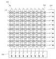
도 3은 본 발명에 따른 원격제스처 인식이 가능한 터치스크린의 터치인식모드에서의 구동방식을 나타낸 도면이다.
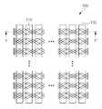
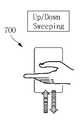
도 4a는 본 발명에 따른 원격제스처 인식이 가능한 터치스크린의 원격제스처 인식모드에서의 제 1 전극패턴의 그룹핑 방식을 나타낸 회로도이며, 도 4b는 상기 제 1 전극패턴이 그룹핑 된 경우, 사용자의 상,하 방향의 스위핑 제스처를 나타낸 도면이다.
도 5a는 본 발명에 따른 원격제스처 인식이 가능한 터치스크린의 원격제스처 인식모드에서의 제 2 전극패턴의 그룹핑 방식을 나타낸 회로도이며, 도 5b는 상기 제 2 전극패턴이 그룹핑 된 경우, 사용자의 좌,우 방향의 스위핑 제스처를 나타낸 도면이다.
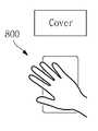
도 6은 본 발명에 따른 원격제스처 인식이 가능한 터치스크린의 원격제스처 인식모드를 종료시키는 제스처를 나타낸 도면이다.
도 7은 본 발명에 따른 원격제스처 인식이 가능한 터치스크린의 제어방법을 나타낸 흐름도이다.
도 8은 본 발명에 따른 원격제스처 인식이 가능한 터치스크린의 제어부를 나타낸 도면이다.1 is a block diagram of a touch screen capable of recognizing a remote gesture according to an embodiment of the present invention.
FIG. 2A is a plan view of the touch panel of the present invention, and FIG. 2B is a sectional view taken along the line A-A 'of FIG. 2A.
3 is a diagram illustrating a driving method in a touch recognition mode of a touch screen capable of recognizing a remote gesture according to the present invention.
FIG. 4A is a circuit diagram illustrating a method of grouping a first electrode pattern in a remote gesture recognition mode of a touch screen capable of recognizing a remote gesture according to the present invention. FIG. Downward sweeping gesture.
5A is a circuit diagram illustrating a method of grouping second electrode patterns in a remote gesture recognition mode of a touch screen capable of recognizing a remote gesture according to the present invention. Right direction sweeping gesture.
FIG. 6 illustrates a gesture for terminating a remote gesture recognition mode of a touch screen capable of recognizing a remote gesture according to the present invention.
FIG. 7 is a flowchart illustrating a method of controlling a touch screen capable of recognizing a remote gesture according to the present invention.
FIG. 8 is a diagram illustrating a controller of a touch screen capable of recognizing a remote gesture according to the present invention.
본 발명의 목적, 특정한 장점들 및 신규한 특징들은 첨부된 도면들과 연관되어지는 이하의 상세한 설명과 바람직한 실시예들로부터 더욱 명백해질 것이다. 본 명세서에서 각 도면의 구성요소들에 참조번호를 부가함에 있어서, 동일한 구성 요소들에 한해서는 비록 다른 도면상에 표시되더라도 가능한 한 동일한 번호를 가지도록 하고 있음에 유의하여야 한다. 또한, "일면", "타면", "제1", "제2" 등의 용어는 하나의 구성요소를 다른 구성요소로부터 구별하기 위해 사용되는 것으로, 구성요소가 상기 용어들에 의해 제한되는 것은 아니다. 이하, 본 발명을 설명함에 있어서, 본 발명의 요지를 불필요하게 흐릴 수 있는 관련된 공지 기술에 대한 상세한 설명은 생략한다.
BRIEF DESCRIPTION OF THE DRAWINGS The objectives, specific advantages and novel features of the present invention will become more apparent from the following detailed description taken in conjunction with the accompanying drawings, in which: FIG. It should be noted that, in the present specification, the reference numerals are added to the constituent elements of the drawings, and the same constituent elements are assigned the same number as much as possible even if they are displayed on different drawings. Also, the terms "one side,"" first, ""first,"" second, "and the like are used to distinguish one element from another, no. DETAILED DESCRIPTION OF THE PREFERRED EMBODIMENTS In the following description of the present invention, detailed description of related arts which may unnecessarily obscure the gist of the present invention will be omitted.
이하, 첨부된 도면을 참조하여 본 발명의 바람직한 실시예를 상세히 설명하기로 한다.Hereinafter, preferred embodiments of the present invention will be described in detail with reference to the accompanying drawings.
도 1은 본 발명의 실시예에 따른 원격제스처 인식이 가능한 터치스크린의 블럭도이며, 도 2a는 본 발명의 터치패널의 평면도이고, 도 2b는 도 2a의 A - A'를 기준으로 터치패널을 절단한 단면도이고, 도 8은 상기 터치스크린의 제어부를 나타낸 도면이다.1 is a block diagram of a touch screen capable of recognizing a remote gesture according to an embodiment of the present invention. FIG. 2A is a plan view of the touch panel of the present invention, FIG. 2B is a cross- FIG. 8 is a view illustrating a control unit of the touch screen. FIG.
도 1 및 8에 도시된 바와 같이, 본 발명의 실시예에 따른 원격제스처 인식이 가능한 터치스크린은 터치패널, 제 1 스위칭 회로부, 제 2 스위칭 회로부, 제어부 및 모드 선택부를 포함하며, 상기 제어부는 감지회로모듈, 신호변환모듈, 연산모듈, 구동회로모듈 및 컨트롤러를 포함한다.
1 and 8, a touch screen capable of recognizing a remote gesture according to an embodiment of the present invention includes a touch panel, a first switching circuit unit, a second switching circuit unit, a control unit, and a mode selection unit, A circuit module, a signal conversion module, a calculation module, a drive circuit module, and a controller.
터치패널(100)은 도 2a 및 도 2b에 도시된 바와 같이, 기판(120), 상기 기판(120)의 일면에 일방향으로 상호 평행하게 형성되는 제 1 전극패턴 (110)및 상기 기판(120)의 배면에 형성되며, 상기 제 1 전극패턴(110)에 교차되는 방향으로 상호 평행하게 형성되는 제 2 전극패턴(130)을 포함한다.2A and 2B, the
여기에서, 기판(120)은 전극패턴, 전극배선등이 형성될 영역을 제공하는 역할을 수행하며, 소정강도 이상을 보유한 재질이라면 특별히 한정되는것은 아니지만, 폴리에틸렌테레프탈레이트(PET), 폴리카보네이트(PC), 폴리메틸메타아크릴레이트(PMMA), 유리 또는 강화유리 등으로 형성하는 것이 바람직하다.
Here, the substrate 120 serves as a region for forming an electrode pattern, an electrode wiring, and the like, and is not particularly limited as long as it has a predetermined strength or more. However, the substrate 120 may be made of polyethylene terephthalate (PET), polycarbonate ), Polymethyl methacrylate (PMMA), glass or tempered glass, or the like.
제 1전극패턴(110)은 구리(Cu), 알루미늄(Al), 금(Au), 은(Ag), 티타늄(Ti), 팔라듐(Pd), 크롬(Cr) 또는 이들의 조합을 이용하여 메시패턴(Mesh Pattern)으로 형성할 수 있으며, 제 2 전극패턴(130)은 메시패턴(Mesh Pattern) 또는 solid 형태의 Bar 전극구조로 형성될 수 있다.The
그리고, 종래의 상호유도 정전용량방식 터치스크린의 경우에, 제1전극패턴(상부전극패턴)(110)은 제2전극패턴(하부전극패턴)(130)과 터치입력수단과의 전기장에 의한 커플링(coupling)을 차단하지 않기 위해서, 저항한계를 기준으로 제2전극패턴(하부전극패턴)(130)보다 상대적으로 좁은 폭을 갖도록 형성되었으나, 상기 제1전극패턴을 광폭의 금속메쉬패턴으로 형성하는 경우에는 터치인식 및 원격제스처 인식이 모두 가능한 SNR을 얻을 수 있다.In the case of a conventional mutual inductive capacitive touch screen, a first electrode pattern (upper electrode pattern) 110 is connected to a second electrode pattern (lower electrode pattern) 130 and a couple (Lower electrode pattern) 130 on the basis of the resistance limit so as not to block the coupling, the first electrode pattern is formed into a wide metal mesh pattern , It is possible to obtain a SNR capable of both touch recognition and remote gesture recognition.
즉, 제1전극패턴(110)을 금속메쉬패턴으로 형성하는 경우에는 터치입력수단과의 전기장에 의한 커플링(coupling)을 차단하지 않기 때문에, 제2전극패턴의 형성구조(메시패턴(Mesh Pattern) 또는 solid 형태의 Bar 전극구조)와 상관없이, 제 1전극패턴의 폭을 제2전극패턴의 폭과 동일 또는 유사하게 형성하더라도, 상기 터치인식 및 원격제스처 인식을 위한 SNR을 확보할 수 있다.
That is, when the
모드 선택부(500)는 사용자의 선택에 따라, 터치인식모드 와 원격제스처 인식모드 중 상기 터치패널의 작동모드를 선택하는 역할을 수행하며, H/W 또는 S/W 버튼으로 구성될 수 있다.The
제 1 및 2 스위칭 회로부(200,300)는 상기 터치패널(100)의 작동모드 선택에 따라 제 1 및 2 전극패턴(X1~X9,Y1~Y9)(110,130) 과 스위칭 동작을 통해 전기적으로 상호 연결된다.The first and second
즉, 제어부(400)는 상기 제 1 스위칭 회로부(200) 및 제 2 스위칭 회로부(300)의 스위칭 동작 및 상기 제 1 전극패턴(X1~X9) 과 상기 제 2 전극패턴(Y1~Y9)에 인가되는 구동신호를 제어하고, 상기 제 1 전극패턴(110) 및 제 2전극패턴(130)에서 감지된 정전용량의 변화를 검출한다.That is, the
여기에서, 제어부(400)는 감지회로모듈(410), 신호변환모듈(420), 연산모듈(430), 구동회로모듈(440) 및 컨트롤러(450)를 포함한다. 감지회로모듈(410)은 제2스위칭 회로부(300)에 연결되며, 상기 터치패널(100)에서의 정전용량 변화를 감지하고, 이에 대응한 아날로그신호(전압형태)를 생성하며, 신호변환모듈(420)은 감지회로모듈(410)에 연결되며, 상기 아날로그 신호(전압형태)를 디지털 신호로 변환하며, 상기 신호변환방식은 상기 아날로그 신호가 소정의 기준 전압레벨까지 도달하는 시간을 측정하여, 이를 디지털 신호로 변환하는 TDC(Time-to-digital converter)방식 또는 상기 아날로그 신호의 레벨이 소정시간동안 변화하는 양을 측정하여 이를 디지털 신호로 변환하는 ADC(Analog-to-digital converter)방식일 수 있다. 또한, 연산모듈(430)은 상기 디지털 신호를 이용하여, 터치패널에 인가된 터치입력의 갯수, 좌표 또는 제스처 동작등을 판단하며, 구동회로모듈은 상기 제1스위칭 회로부에 연결되며, 상기 터치패널에 소정의 구동신호를 인가한다.The
그리고, 컨트롤러(450)는 감지회로모듈(410), 신호변환모듈(420), 연산모듈(430), 구동회로모듈(440) 및 제1및2 스위칭 회로부의 작동을 제어한다. 여기에서, 컨트롤러(450)는 MCU(Micro controller unit) 일 수 있다.
The
이하, 터치패널의 작동모드 선택에 따른 원격제스처 인식이 가능한 터치스크린의 구동방식에 대해 보다 상세히 설명할 것이다.
Hereinafter, the driving method of the touch screen capable of recognizing the remote gesture according to the operation mode selection of the touch panel will be described in detail.
도 3은 본 발명에 따른 원격제스처 인식이 가능한 터치스크린의 터치인식모드에서의 구동방식을 나타낸 회로도이다.3 is a circuit diagram showing a driving method in a touch recognition mode of a touch screen capable of recognizing a remote gesture according to the present invention.
사용자에 의해 모드선택부(500)에서 터치인식모드가 선택된 경우에, 컨트롤러(450)는 제 1 및 2 스위칭 회로부의 스위칭 동작을 제어하여, 제 1 및 2스위칭 회로부가 제1 및 2전극패턴들에 모두 전기적으로 연결되도록 제어한다.
The
그리고, 구동신호모듈(440)은 제 2 스위칭 회로부(300)를 통해 제 2전극패턴(130)에 순차적으로 구동신호를 인가하며, 감지회로모듈(410)은 사용자의 터치입력에 따라 각각의 제 1 전극패턴(110)에서 감지되는 상호유도 정전용량변화를 검출하여, 연산모듈(130)을 통해 상호유도 정전용량이 변화된 터치위치의 좌표를 판별한다.The driving
즉, 감지회로모듈(410)은 제 1 전극패턴(110)에서 감지된 상호정전용량값을 전압값으로 변환한 후, 상기 전압값을 기준값 (Base line)으로 설정한 후, 구동신호모듈이 제 2 전극패턴(130)에 순차적으로 구동신호를 인가후, 감지회로모듈(410)이 제 1 전극패턴(110)에서의 상호정전용량을 검출하는 과정을 반복수행하여, 상기 기준값(Baseline)을 업데이팅(Updating)한다.
That is, the
도 4a 와 5a 는 본 발명에 따른 원격제스처 인식이 가능한 터치스크린의 원격제스처 인식모드에서의 제 1 및 2 전극패턴의 그룹핑 방식을 나타낸 도면이며, 도 4b 와 5b 는 제 1 및 2 전극패턴 그룹이 형성된 후, 사용자의 상,하 및 좌,우 방향의 스위핑 제스처를 나타낸 도면이고, 도 6은 원격제스처 인식모드를 종료시키기 위한 제스처를 나타낸 도면이다.
FIGS. 4A and 5A are views showing a method of grouping first and second electrode patterns in a remote gesture recognition mode of a touch screen capable of recognizing a remote gesture according to the present invention. FIGS. 4B and 5B illustrate first and second electrode pattern groups FIG. 6 is a view showing a gesture for ending the remote gesture recognition mode. FIG. 6 is a view showing a sweeping gesture of the user in the up, down, left, and right directions after the formation.
도 4a 내지 도 5b 에 도시된 바와 같이, 사용자에 의해 모드 선택부(500)에서 원격제스처 인식모드가 선택된 경우, 컨트롤러(450)는 제 1 스위칭 회로부(200)의 스위칭 동작을 제어하여, 적어도 하나의 제 1 전극패턴(110)들로 이루어진 제 1 전극패턴 그룹(G1,G2)을 형성한 후, 제 2 스위칭 회로부(300)의 스위칭 동작을 제어하여, 적어도 하나의 제 2 전극패턴(130)들로 이루어진 제 2 전극패턴 그룹(G3,G4)을 형성한다.4A and 5B, when the remote gesture recognition mode is selected by the user in the
여기에서, 구동신호모듈(440)은 제 2 스위칭회로부(200)를 통해 제 1 전극패턴 그룹(G1,G2)에 순차적으로 구동신호를 인가하고, 감지회로모듈은 상기 제 1 전극패턴 그룹(G1,G2)에서 감지된 자기유도 정전용량의 변화에 대한 시간차이를 감지한 후, 상기 정전용량의 변화에 대응하는 아날로그 신호(전압)를 생성하며, 상기 신호는 신호변환모듈(420) 및 연산모듈(430)를 통해 계산된 결과를 바탕으로 컨트롤러(450)는 사용자의 상,하 방향의 제스처 입력여부(700)를 판단한다.
Here, the driving
또한, 컨트롤러(450)는 제 2 스위칭회로부(300)를 통해 제 2 전극패턴 그룹(G3,G4)에 순차적으로 구동신호를 인가하고, 상기 제 2 전극패턴 그룹(G3,G4)에서 감지된 셀프 커패시턴스의 변화를 검출하여, 사용자의 좌우 방향의 제스처 입력여부(600)를 판단한다.The
즉, 구동회로모듈(440)은 제 2 스위칭회로부(200)를 통해 제 2 전극패턴 그룹(G3,G4)에 순차적으로 구동신호를 인가하고, 감지회로모듈(410)은 상기 제 2 전극패턴 그룹(G3,G4)에서 감지된 감지된 자기유도 정전용량의 변화에 대한 시간차이를 감지한 후, 상기 정전용량의 변화에 대응하는 아날로그 신호(전압)를 생성하며, 상기 신호는 신호변환모듈(420) 및 연산모듈(430)를 통해 계산된 결과를 바탕으로 컨트롤러(450)는 사용자의 좌,우 방향의 제스처 입력여부(700)를 판단한다.
That is, the driving
그리고, 제어부(400)는 제1및 2전극패턴 그룹의 갯수 및 중간전극(G1,G2,G3,G4이외의 전극패턴)의 전위상태등을 조정하여, 원격제스처를 인식할 수 있는 범위를 조정할 수 있으며, 바람직하게는 4인치 디스플레이 기준으로 5cm 이상 10 cm 이내의 제스처의 움직임을 감지할 수 있다.
The
그리고, 도 6에 도시된 바와 같이, 사용자의 제스처가 터치패널을 덮는 커버(cover) 동작이 감지된 경우에, 제어부(400)는 상기 커버동작을 원격제스처 인식모드를 종료시키는 제스처로 인식하고, 제 1 및 2 스위칭 회로부(200,300)의 스위칭 동작을 제어하여, 제 1 및 2 스위칭 회로부(200,300)의 스위치가 제 1 및 2 전극패턴(110,130)들에 모두 전기적으로 연결되도록 함으로써, 제 1 및 2 전극패턴 그룹(G1,G2,G3,G4)이 해제되도록 한다. 여기에서, 원격제스처 인식모드를 종료시키는 제스처는 상기 커버(cover) 동작에 한정되지 않는다.
6, when a cover operation in which the user's gesture covers the touch panel is sensed, the
상기에서 살펴본 바와 같이, 본 발명에 따르면, 제 1 및 2 스위칭 회로부의 스위칭 동작을 통해 종래의 상호유도 정전용량방식 터치스크린의 전극패턴을 스위칭 회로부를 통해 그룹핑하여,자기유도 정전방식을 위한 새로운 감지 전극을 생성하여, 터치 및 원격제스처 인식기능을 상기 전극패턴에 일체화함으로써, 복수의 센싱기능이 포함된 상기 터치스크린을 경박단소화할 수 있다.
As described above, according to the present invention, the electrode patterns of the conventional mutual inductive capacitive touch screen are grouped through the switching circuit unit through the switching operation of the first and second switching circuit units, and a new sensing Electrodes are formed and the touch and remote gesture recognition functions are integrated with the electrode pattern, the touch screen including a plurality of sensing functions can be thinned and shortened.
또한, 외부적으로 터치입력이 곤란한 상황에서도 사용자의 제스처에 의한 자기유도 정전용량(self-capacitance)변화의 시간차이를 검출하여, 상기 제스처에 대응하는 기능을 수행함으로써, 상기 제스처를 통해 휴대용기기 또는 컨텐츠등을 제어할 수 있다.
Further, it is possible to detect a time difference of a self-capacitance change due to a user's gesture even when a touch input is difficult externally, and perform a function corresponding to the gesture, Content and the like can be controlled.
또한, 터치스크린의 제1전극패턴의 폭을 기존의 상호유도 정전용량방식보다 광폭의 금속메쉬패턴으로 형성함으로써, 터치 및 원격제스처 인식에 모두 사용가능한 SNR(Signal to noise ratio)을 확보할 수 있다.
Further, by forming the width of the first electrode pattern of the touch screen into a metal mesh pattern having a wider width than the conventional mutual inductive capacitive method, a signal to noise ratio (SNR) that can be used for both touch and remote gesture recognition can be ensured .
도 7은 본 발명에 따른 원격제스처 인식이 가능한 터치스크린의 제어방법을 나타낸 흐름도이다. 도 7에 도시된 바와 같이, 원격제스처 인식이 가능한 터치스크린의 제어방법은 터치인식모드단계(S100), 모드선택단계(S110), 원격제스처 인식모드 수행단계(S130,140), 원격제스처 인식모드 종료여부 판단단계(S150), 원격제스처 인식모드 종료단계(S160) 및 터치인식모드의 종료여부 판단단계(S120)를 포함한다.
FIG. 7 is a flowchart illustrating a method of controlling a touch screen capable of recognizing a remote gesture according to the present invention. 7, the control method of the touch screen capable of recognizing the remote gesture includes a touch recognition mode step S100, a mode selection step S110, a remote gesture recognition mode execution step S130 and 140, a remote gesture recognition mode (S150), ending the remote gesture recognition mode (S160), and determining whether the touch recognition mode is terminated (S120).
먼저, 터치인식모드단계(S100)에서는 구동신호모듈(440)은 제 2 스위칭 회로부(300)를 통해 제 2전극패턴(130)에 순차적으로 구동신호를 인가하며, 감지회로모듈(410)은 사용자의 터치입력에 따라 각각의 제 1 전극패턴(110)에서 감지되는 상호유도 정전용량변화를 검출하여, 연산모듈(430)를 통해 상호유도 정전용량이 변화된 터치위치의 좌표를 판별한다.
The driving
다음으로 모드선택단계(S110)에서는 사용자가 모드선택부(500)를 통해 상기 터치 방식 모드에서 원격제스처 인식 모드로의 전환여부를 선택하며, 원격제스처 인식모드를 선택하지 않은 경우에는 상기 터치인식모드 종료여부 판단 단계를 수행한다.(S120)
Next, in the mode selection step S110, the user selects whether to switch from the touch mode to the remote gesture recognition mode through the
그리고, 사용자가 상기 원격제스처 인식모드를 선택한 경우에 제어부(400)는 제 1 및 2 스위칭 회로부(200,300)의 스위칭 동작을 통해 적어도 하나의 제 1 및 2 전극패턴(110,130)들로 이루어진 제 1 및 2 전극패턴 그룹(G1,G2,G3,G4)을 형성한 후(S130), 사용자의 제스처에 따른 상기 제 1 및 2 전극패턴 그룹(G1,G2,G3,G4)의 자기유도 정전용량의 변화에 대한 시간차이를 검출하는 원격제스처 인식모드를 수행한다(S140)When the user selects the remote gesture recognition mode, the
여기에서, 제어부(400)는 제 1 및 2 스위칭 회로부(200,300)를 통해 제 1 및 2 전극패턴 그룹(G1,G2,G3,G4)에 순차적으로 구동신호를 인가하고, 상기 제 1 및 2 전극패턴 그룹(G1,G2,G3,G4)에서 감지된 자기유도 정전용량의 변화에 대한 시간차이를 검출하여, 사용자 제스처의 움직임 방향(상->하 또는 좌-> 우 방향)을 결정한다.
Here, the
또한, 제어부(400)는 사용자의 특정 제스처 입력여부를 판단하여, 상기 원격제스처 인식모드 종료여부를 판단한다(S150). 즉, 도 6에 도시된 바와 같이, 사용자가 터치패널을 덮은 커버(cover)제스처를 입력한 경우에, 제어부(400)는 상기 제스처를 상기 원격제스처 인식모드를 종료하는 것으로 인식한다.
In addition, the
다음으로, 사용자의 특정 제스처의 입력이 있는 경우에, 제어부(400)는 제 1 및 2 스위칭 회로부(200,300)의 스위칭 동작을 제어하여, 제 1 및 2 스위칭 회로부(200,300)의 스위치가 제 1 및 2전극패턴들(110,130)에 모두 전기적으로 연결되게 함으로써, 제 1 및 2 전극패턴 그룹핑을 해제한다(S160).
Next, when there is an input of the user's specific gesture, the
그리고, 제 1 및 2 전극패턴 그룹핑이 해제된 이후에, 사용자는 상기 터치인식모드의 재수행여부를 선택한다(S120). 즉, 사용자가 상기 터치인식모드의 재수행을 원하는 경우에는 터치인식모드 수행단계(S100)을 다시 수행하며, 그렇지 않은 경우에는 상기 터치인식모드는 종료한다.
After the first and second electrode pattern grouping is released, the user selects whether to perform the touch recognition mode again (S120). That is, if the user desires to perform the touch recognition mode again, the user performs the touch recognition mode execution step (S100) again. Otherwise, the touch recognition mode ends.
이상 본 발명을 구체적인 실시예를 통하여 상세히 설명하였으나, 이는 본 발명을 구체적으로 설명하기 위한 것으로, 본 발명에 따른 원격제스처 인식이 가능한 터치스크린은 이에 한정되지 않으며, 본 발명의 기술적 사상 내에서 당해 분야의 통상의 지식을 가진 자에 의해 그 변형이나 개량이 가능함은 명백하다고 할 것이다.While the present invention has been particularly shown and described with reference to exemplary embodiments thereof, it is to be understood that the scope of the invention is not limited to the disclosed exemplary embodiments. It will be apparent that modifications and improvements can be made by those skilled in the art.
본 발명의 단순한 변형 내지 변경은 모두 본 발명의 영역에 속하는 것으로 본 발명의 구체적인 보호 범위는 첨부된 특허청구범위에 의하여 명확해질 것이다.
It will be understood by those skilled in the art that various changes in form and details may be made therein without departing from the spirit and scope of the invention as defined by the appended claims.
10 : 원격제스처 인식이 가능한 터치패널을 포함한 휴대용기기
100 : 터치패널 110 : 제 1 전극패턴
120 : 윈도우 기판 130 : 제 2 전극패턴
200 : 제 1 스위칭 회로부 300 : 제 2 스위칭 회로부
400 : 제어부 410 : 감지회로 모듈
420 : 신호변환모듈 430 : 연산모듈
440: 구동회로 모듈 450 : 컨트롤러
500 : 모드 선택부 600 : 좌 / 우 방향의 스위핑 제스쳐
700 : 상 / 하 방향의 스위핑 제스처 800 : 커버동작
G1 , G2 : 제 1 전극패턴 그룹 G3 , G4: 제 2 전극패턴 그룹10: Portable device with remote gesture-recognizable touch panel
100: touch panel 110: first electrode pattern
120: a window substrate 130: a second electrode pattern
200: first switching circuit unit 300: second switching circuit unit
400: control unit 410: sensing circuit module
420: Signal conversion module 430: Operation module
440: drive circuit module 450: controller
500: mode selection unit 600: sweeping gesture in left / right direction
700: sweeping gesture in up / down direction 800: cover operation
G1 and G2 : first electrode pattern groups G3 and G4 : The second electrode pattern group
Claims (16)
Translated fromKorean터치인식모드 와 원격제스처 인식모드 중 상기 터치패널의 작동모드를 선택하는 모드선택부;
상기 터치패널의 작동모드 선택에 따라 제 1 전극패턴 과 스위칭 동작을 통해 전기적으로 연결되는 제 1 스위칭 회로부;
상기 터치패널의 작동모드 선택에 따라 제 2 전극패턴과 스위칭 동작을 통해 전기적으로 연결되는 제 2 스위칭 회로부;및
상기 터치패널의 작동모드 선택에 따라, 상기 제 1 스위칭 회로부 및 제 2 스위칭 회로부의 스위칭 동작 및 상기 제 1 전극패턴 과 상기 제 2 전극패턴에 인가되는 구동신호를 제어하고, 상기 제 1 전극패턴 및 제 2전극패턴에서 감지된 정전용량의 변화를 검출하는 제어부
를 포함하는 원격제스처 인식이 가능한 터치스크린.
A touch panel including a plurality of first electrode patterns and a second electrode pattern formed in a direction intersecting with each other on a substrate;
A mode selection unit for selecting an operation mode of the touch panel among the touch recognition mode and the remote gesture recognition mode;
A first switching circuit part electrically connected to the first electrode pattern through a switching operation according to an operation mode selection of the touch panel;
A second switching circuit part electrically connected to the second electrode pattern through a switching operation according to an operation mode selection of the touch panel;
Wherein the control unit controls the switching operation of the first switching circuit unit and the second switching circuit unit and the driving signal applied to the first electrode pattern and the second electrode pattern according to the operation mode selection of the touch panel, A control unit for detecting a change in capacitance sensed by the second electrode pattern,
A remote gesture-recognizable touch screen.
상기 모드선택부에서 터치인식모드가 선택된 경우,
상기 제 1 스위칭 회로부는 스위칭 동작을 통해 상기 제 1 전극패턴들에 모두 전기적으로 연결되며,
상기 제 2 스위칭 회로부는 스위칭 동작을 통해 상기 제 2 전극패턴들에 모두 전기적으로 연결되고,
상기 제어부는 상기 제 2 스위칭 회로부를 통해 상기 제 2전극패턴에 순차적으로 구동신호를 인가하고, 상기 제 1 전극패턴에서 감지되는 상호정전용량변화를 검출하여, 터치위치를 판별하는 것을 특징으로 하는 원격제스처 인식이 가능한 터치스크린.
The method according to claim 1,
When the touch recognition mode is selected by the mode selection unit,
The first switching circuit part is electrically connected to the first electrode patterns through a switching operation,
Wherein the second switching circuit part is electrically connected to the second electrode patterns through a switching operation,
Wherein the controller sequentially applies a driving signal to the second electrode pattern through the second switching circuit unit and detects a mutual capacitance change sensed by the first electrode pattern to determine a touch position. Gesture-aware touch screen.
상기 모드 선택부에서 원격제스처 인식모드가 선택된 경우,
상기 제 1 스위칭 회로부는 스위칭 동작을 통해 적어도 하나의 제 1 전극패턴들로 이루어진 제 1 전극패턴 그룹을 형성하고,
상기 제 2 스위칭 회로부는 스위칭 동작을 통해 적어도 하나의 제 2 전극패턴들로 이루어진 제 2 전극패턴 그룹을 형성하며,
상기 제어부는 상기 제 1 스위칭부를 통해 상기 제 1 전극패턴 그룹에 순차적으로 구동신호를 인가하고, 사용자의 상하 방향의 제스처 입력에 따른 상기 제 1 전극패턴 그룹에서의 자기유도 정전용량의 변화에 대한 시간적 차이를 감지하여, 상기 사용자의 상하 방향의 제스처 입력여부를 판단하고,
상기 제 2 스위칭부를 통해 상기 제 2 전극패턴 그룹에 순차적으로 구동신호를 인가하고, 사용자의 좌우 방향의 제스처 입력에 따른 상기 제 2 전극패턴 그룹에서의 자기유도 정전용량의 변화에 대한 시간적 차이를 감지하여, 상기 사용자의 좌우 방향의 제스처 입력여부를 판단하는 것을 특징으로 하는 원격제스처 인식이 가능한 터치스크린.
The method according to claim 1,
When the remote gesture recognition mode is selected in the mode selection unit,
Wherein the first switching circuit part forms a first electrode pattern group composed of at least one first electrode patterns through a switching operation,
The second switching circuit part forms a second electrode pattern group composed of at least one second electrode patterns through a switching operation,
Wherein the control unit sequentially applies a driving signal to the first electrode pattern group through the first switching unit and changes a time constant of a change in the magnetic induction capacitance in the first electrode pattern group according to a gesture input of the user in a vertical direction Detects a difference, judges whether or not the user inputs a gesture in the vertical direction,
A driving signal is sequentially applied to the second electrode pattern group through the second switching unit to detect a temporal difference with respect to a change in the magnetic induction electrostatic capacity in the second electrode pattern group according to a gesture input in the left- And determining whether the user inputs gestures in the left and right directions.
상기 터치패널은
기판, 상기 기판의 일면에 일방향으로 상호 평행하게 형성되는 제 1 전극패턴 및 상기 기판의 배면에 형성되며, 상기 제 1 전극패턴에 교차되는 방향으로 상호 평행하게 형성되는 제 2 전극패턴을 포함하는 원격제스처 인식이 가능한 터치스크린..
The method according to claim 1,
The touch panel
And a second electrode pattern formed on a back surface of the substrate and formed in parallel to each other in a direction intersecting the first electrode pattern, the first electrode pattern being formed on one surface of the substrate, Touch screen with gesture recognition ..
상기 제 1 전극패턴은 메쉬패턴인 것을 특징으로 하는 원격제스처 인식이 가능한 터치스크린.
The method of claim 4,
Wherein the first electrode pattern is a mesh pattern.
상기 제 1 전극패턴의 폭은 상기 제 2 전극패턴의 폭과 유사한 것을 특징으로 하는 원격제스터 인식이 가능한 터치스크린.
The method of claim 5,
Wherein the width of the first electrode pattern is similar to the width of the second electrode pattern.
상기 제어부는
상기 터치패널에 소정의 구동신호를 인가하는 구동회로모듈;
상기 터치패널에서의 정전용량 변화를 감지하고, 이에 대응한 아날로그신호를 생성하는 감지회로모듈;
상기 아날로그 신호를 디지털 신호로 변환하는 신호변환모듈;
상기 디지털 신호를 이용하여, 터치패널에 인가된 터치입력의 좌표등을 연산하는 연산모듈; 및
상기 제 1 및 2 스위칭 회로부, 상기 구동회로모듈, 상기 신호변환모듈 과 상기 연산모듈을 제어하는 컨트롤러를 포함하는 원격제스처 인식이 가능한 터치스크린.
7. The method according to any one of claims 1 to 6,
The control unit
A drive circuit module for applying a predetermined drive signal to the touch panel;
A sensing circuit module for sensing a capacitance change in the touch panel and generating an analog signal corresponding to the capacitance change;
A signal conversion module for converting the analog signal into a digital signal;
A calculation module for calculating coordinates of a touch input applied to the touch panel using the digital signal; And
And a controller for controlling the first and second switching circuit units, the driving circuit module, the signal conversion module, and the calculation module.
상기 터치 방식 모드에서 원격제스처 인식 모드로의 전환여부를 선택하는 모드 선택 단계;
상기 원격제스처 인식모드를 선택한 경우, 제 1 및 2 전극패턴 그룹을 형성한 후, 사용자의 제스처에 따른 상기 제 1 및 2 전극패턴 그룹의 자기유도 정전용량의 변화에 대한 시간적 차이를 감지하는 원격제스처 인식모드 수행단계; 및
특정 제스처 입력여부에 따라 상기 원격제스처 인식모드에서 상기 터치 인식 모드로의 전환여부를 선택하는 원격제스처 인식모드 종료여부 판단단계를
포함하는 것을 특징으로 하는 원격제스처 인식이 가능한 터치스크린의 제어방법.
A touch mode step of detecting a touch position by detecting a change in mutual inductive capacitance detected in the first electrode pattern according to a drive signal sequentially applied to a second electrode pattern of the touch panel;
A mode selection step of selecting whether to switch from the touch mode to the remote gesture recognition mode;
When the remote gesture recognition mode is selected, a remote gesture for detecting a temporal difference in a change in the magnetic induction electrostatic capacity of the first and second electrode pattern groups according to a gesture of the user after forming the first and second electrode pattern groups, A recognition mode performing step; And
Determining whether or not to switch from the remote gesture recognition mode to the touch recognition mode according to whether a specific gesture is input or not;
Wherein the remote gesture recognition method comprises the steps of:
상기 터치패널은
기판, 상기 기판의 일면에 일방향으로 상호 평행하게 형성되는 제 1 전극패턴 및 상기 기판의 배면에 형성되며, 상기 제 1 전극패턴에 교차되는 방향으로 상호 평행하게 형성되는 제 2 전극패턴을 포함하는 것을 특징으로 하는 원격제스처 인식이 가능한 터치스크린의 제어방법.
The method of claim 8,
The touch panel
And a second electrode pattern formed on a back surface of the substrate and formed parallel to each other in a direction intersecting the first electrode pattern, the first electrode pattern being formed on one surface of the substrate in parallel with the first electrode pattern, A method of controlling a touch screen capable of recognizing a remote gesture.
상기 제 1 전극패턴은 메쉬패턴인 것을 특징으로 하는 원격제스처 인식이 가능한 터치스크린의 제어방법.
Claim 8
Wherein the first electrode pattern is a mesh pattern.
상기 제 1 전극패턴의 폭은 상기 제 2 전극패턴의 폭과 유사한 것을 특징으로 하는 원격제스터 인식이 가능한 터치스크린.
The method of claim 10,
Wherein the width of the first electrode pattern is similar to the width of the second electrode pattern.
상기 원격제스처 인식모드 수행단계는
제 1 스위칭 회로부의 스위칭 동작을 통해 적어도 하나의 제 1 전극패턴들로 이루어진 제 1 전극패턴 그룹을 형성하고,
제 2 스위칭 회로부의 스위칭 동작을 통해 적어도 하나의 제 2 전극패턴들로 이루어진 제 2 전극패턴 그룹을 형성하는 것을 특징으로 하는 원격제스처 인식이 가능한 터치스크린의 제어방법.
The method of claim 8,
The remote gesture recognition mode performing step
A first electrode pattern group composed of at least one first electrode patterns is formed through a switching operation of the first switching circuit section,
And a second electrode pattern group including at least one second electrode patterns is formed through the switching operation of the second switching circuit unit.
상기 원격제스처 인식모드 수행단계는
상기 제 1 스위칭회로부를 통해 상기 제 1 전극패턴 그룹에 순차적으로 구동신호가 인가되고, 사용자의 상하 방향의 제스처 입력에 따른 상기 제 1 전극패턴 그룹에서의 자기유도 정전용량의 변화에 대한 시간적 차이를 감지하여, 상기 사용자의 상하 방향의 제스처 입력여부를 판단한 후,
상기 제 2 스위칭회로부를 통해 상기 제 2 전극패턴 그룹에 순차적으로 구동신호를 인가하고, 사용자의 좌우 방향의 제스처 입력에 따른 상기 제 2 전극패턴 그룹에서의 자기유도 정전용량의 변화에 대한 시간적 차이를 감지하여, 상기 사용자의 좌우 방향의 제스처 입력여부를 판단하는 것을 특징으로 하는 원격제스처 인식이 가능한 터치스크린의 제어방법.
The method of claim 12,
The remote gesture recognition mode performing step
A driving signal is sequentially applied to the first electrode pattern group through the first switching circuit unit and a temporal difference with respect to a change in the magnetic induction capacitance in the first electrode pattern group according to the gesture input of the user in the up and down direction Determines whether or not the user inputs a gesture in the vertical direction,
A driving signal is sequentially applied to the second electrode pattern group through the second switching circuit unit and a temporal difference with respect to a change in the magnetic induction capacitance in the second electrode pattern group according to the gesture input in the left- And determining whether the user inputs a gesture in the left and right directions.
상기 원격제스처 인식모드 종료여부 판단단계 이후에,
상기 원격제스처 인식모드가 종료되지 않은 경우, 상기 원격제스처 인식모드 수행단계를 반복적으로 수행하는 것을 특징으로 하는 원격제스처 인식이 가능한 터치스크린의 제어방법.
The method of claim 8,
After the step of determining whether the remote gesture recognition mode is terminated,
And if the remote gesture recognition mode is not terminated, executing the remote gesture recognition mode is repeatedly performed.
상기 원격제스처 인식모드 종료여부 판단단계 이후에,
상기 원격제스처 인식모드가 종료된 경우,상기 제 1 스위칭 회로부가 스위칭 동작을 통해 제 1 전극패턴들에 모두 전기적으로 연결되고,
상기 제 2 스위칭 회로부가 스위칭 동작을 통해 제 2 전극패턴들에 모두 전기적으로 연결됨으로써,
상기 제 1 및 2 전극패턴 그룹이 해제되는 단계를 더 포함하는 것을 특징으로 하는 원격제스처 인식이 가능한 터치스크린을 포함하는 휴대용기기의 제어방법.
The method of claim 8,
After the step of determining whether the remote gesture recognition mode is terminated,
When the remote gesture recognition mode is terminated, the first switching circuit unit is electrically connected to the first electrode patterns through the switching operation,
And the second switching circuit portion is electrically connected to the second electrode patterns through the switching operation,
The method of claim 1, further comprising the step of releasing the first and second electrode pattern groups.
상기 제 1 및 2 전극패턴 그룹이 해제되는 단계이후에,
상기 터치인식모드의 재수행여부를 판단하는 터치인식모드의 종료여부 판단단계를 더 포함하는 것을 특징으로 하는 원격제스처 인식이 가능한 터치스크린의 제어방법.16. The method of claim 15,
After the step of releasing the first and second electrode pattern groups,
Further comprising the step of determining whether the touch recognition mode for determining whether the touch recognition mode is performed again is terminated or not.
Priority Applications (2)
| Application Number | Priority Date | Filing Date | Title |
|---|---|---|---|
| KR20130080420AKR20150006681A (en) | 2013-07-09 | 2013-07-09 | Touch screen to recognize a remote gesture and controlling method thereof |
| US14/061,164US20150015531A1 (en) | 2013-07-09 | 2013-10-23 | Touch screen to recognize remote gesture and controlling method thereof |
Applications Claiming Priority (1)
| Application Number | Priority Date | Filing Date | Title |
|---|---|---|---|
| KR20130080420AKR20150006681A (en) | 2013-07-09 | 2013-07-09 | Touch screen to recognize a remote gesture and controlling method thereof |
Publications (1)
| Publication Number | Publication Date |
|---|---|
| KR20150006681Atrue KR20150006681A (en) | 2015-01-19 |
Family
ID=52276720
Family Applications (1)
| Application Number | Title | Priority Date | Filing Date |
|---|---|---|---|
| KR20130080420ACeasedKR20150006681A (en) | 2013-07-09 | 2013-07-09 | Touch screen to recognize a remote gesture and controlling method thereof |
Country Status (2)
| Country | Link |
|---|---|
| US (1) | US20150015531A1 (en) |
| KR (1) | KR20150006681A (en) |
Families Citing this family (7)
| Publication number | Priority date | Publication date | Assignee | Title |
|---|---|---|---|---|
| US9323398B2 (en) | 2009-07-10 | 2016-04-26 | Apple Inc. | Touch and hover sensing |
| US9851829B2 (en) | 2010-08-27 | 2017-12-26 | Apple Inc. | Signal processing for touch and hover sensing display device |
| US9201547B2 (en) | 2012-04-30 | 2015-12-01 | Apple Inc. | Wide dynamic range capacitive sensing |
| US9933879B2 (en)* | 2013-11-25 | 2018-04-03 | Apple Inc. | Reconfigurable circuit topology for both self-capacitance and mutual capacitance sensing |
| CN104793829B (en)* | 2015-05-08 | 2018-01-26 | 厦门天马微电子有限公司 | A touch device, driving method, array substrate and liquid crystal display panel |
| CN106293225B (en)* | 2016-08-09 | 2023-09-01 | 厦门天马微电子有限公司 | Touch display panel and display device |
| CN108628485B (en)* | 2017-03-16 | 2021-05-04 | 宏碁股份有限公司 | Electronic device with touch function and operation method thereof |
Family Cites Families (4)
| Publication number | Priority date | Publication date | Assignee | Title |
|---|---|---|---|---|
| US8316324B2 (en)* | 2006-09-05 | 2012-11-20 | Navisense | Method and apparatus for touchless control of a device |
| US8525802B2 (en)* | 2008-03-31 | 2013-09-03 | Lg Electronics Inc. | Portable terminal capable of sensing proximity touch and method for providing graphic user interface using the same |
| US8054300B2 (en)* | 2008-06-17 | 2011-11-08 | Apple Inc. | Capacitive sensor panel having dynamically reconfigurable sensor size and shape |
| US9244573B2 (en)* | 2010-03-03 | 2016-01-26 | Miraenanotech Co., Ltd. | Capacitive touch panel including embedded sensing electrodes |
- 2013
- 2013-07-09KRKR20130080420Apatent/KR20150006681A/ennot_activeCeased
- 2013-10-23USUS14/061,164patent/US20150015531A1/ennot_activeAbandoned
Also Published As
| Publication number | Publication date |
|---|---|
| US20150015531A1 (en) | 2015-01-15 |
Similar Documents
| Publication | Publication Date | Title |
|---|---|---|
| KR102016854B1 (en) | Electrical device having multi-functional human interface | |
| KR20150006681A (en) | Touch screen to recognize a remote gesture and controlling method thereof | |
| US10353485B1 (en) | Multifunction input device with an embedded capacitive sensing layer | |
| JP5324440B2 (en) | Hovering and touch detection for digitizers | |
| CN104603729B (en) | Apparatus for determining touch input stimuli | |
| CN205485930U (en) | Input device and keyboard | |
| US20090167719A1 (en) | Gesture commands performed in proximity but without making physical contact with a touchpad | |
| KR101412808B1 (en) | Electronic apparatus and operating method thereof | |
| KR20150030072A (en) | Touch sensor to recognize a gesture and controlling method thereof | |
| KR101362843B1 (en) | Touch screen apparatus and method thereof | |
| US10048759B2 (en) | Input device, particularly computer mouse | |
| KR20100054274A (en) | Touch-input device for acquiring location and intensity of force and method thereof | |
| JP2014112449A (en) | Selective rejection of touch contacts in edge region of touch surface | |
| TW201541314A (en) | System and method for gesture control | |
| CN104866147A (en) | Capacitive Finger Navigation Module And Manufacturing Method Thereof | |
| KR20160028067A (en) | Mobile terminal device and driving method thereof | |
| KR20130049453A (en) | Touch sensing apparatus and operating method thereof | |
| CN102736770A (en) | Multi-point gesture identification method and multi-point translation gesture identification device | |
| JP6068609B2 (en) | Touchpad using piezo effect | |
| KR20150087714A (en) | Touch panel and touchscreen apparatus including the same | |
| KR101619705B1 (en) | Touch Pad Capable of Recognizing Slide Touch Gesture using Piezo Effect | |
| KR20150006328A (en) | Touchscreen apparatus | |
| CN105045431A (en) | Intelligent sensor for touch screen terminal and touch detection method for intelligent sensor | |
| KR20200040623A (en) | Electronic device having multi functional human interface and method for controlling the same | |
| KR101175073B1 (en) | Capacitive touch screen driving system |
Legal Events
| Date | Code | Title | Description |
|---|---|---|---|
| A201 | Request for examination | ||
| PA0109 | Patent application | Patent event code:PA01091R01D Comment text:Patent Application Patent event date:20130709 | |
| PA0201 | Request for examination | ||
| E902 | Notification of reason for refusal | ||
| PE0902 | Notice of grounds for rejection | Comment text:Notification of reason for refusal Patent event date:20140627 Patent event code:PE09021S01D | |
| AMND | Amendment | ||
| PG1501 | Laying open of application | ||
| E601 | Decision to refuse application | ||
| PE0601 | Decision on rejection of patent | Patent event date:20150323 Comment text:Decision to Refuse Application Patent event code:PE06012S01D Patent event date:20140627 Comment text:Notification of reason for refusal Patent event code:PE06011S01I | |
| AMND | Amendment | ||
| PX0901 | Re-examination | Patent event code:PX09011S01I Patent event date:20150323 Comment text:Decision to Refuse Application Patent event code:PX09012R01I Patent event date:20141023 Comment text:Amendment to Specification, etc. | |
| PX0601 | Decision of rejection after re-examination | Comment text:Decision to Refuse Application Patent event code:PX06014S01D Patent event date:20150522 Comment text:Amendment to Specification, etc. Patent event code:PX06012R01I Patent event date:20150420 Comment text:Decision to Refuse Application Patent event code:PX06011S01I Patent event date:20150323 Comment text:Amendment to Specification, etc. Patent event code:PX06012R01I Patent event date:20141023 Comment text:Notification of reason for refusal Patent event code:PX06013S01I Patent event date:20140627 |