KR20150005594A - Air-cleaning device - Google Patents
Air-cleaning deviceDownload PDFInfo
- Publication number
- KR20150005594A KR20150005594AKR1020147031260AKR20147031260AKR20150005594AKR 20150005594 AKR20150005594 AKR 20150005594AKR 1020147031260 AKR1020147031260 AKR 1020147031260AKR 20147031260 AKR20147031260 AKR 20147031260AKR 20150005594 AKR20150005594 AKR 20150005594A
- Authority
- KR
- South Korea
- Prior art keywords
- air
- filter
- fan
- air flow
- flow passage
- Prior art date
- Legal status (The legal status is an assumption and is not a legal conclusion. Google has not performed a legal analysis and makes no representation as to the accuracy of the status listed.)
- Granted
Links
Images


Classifications
- B—PERFORMING OPERATIONS; TRANSPORTING
- B01—PHYSICAL OR CHEMICAL PROCESSES OR APPARATUS IN GENERAL
- B01D—SEPARATION
- B01D46/00—Filters or filtering processes specially modified for separating dispersed particles from gases or vapours
- B01D46/24—Particle separators, e.g. dust precipitators, using rigid hollow filter bodies
- B01D46/2403—Particle separators, e.g. dust precipitators, using rigid hollow filter bodies characterised by the physical shape or structure of the filtering element
- B01D46/2411—Filter cartridges
- F—MECHANICAL ENGINEERING; LIGHTING; HEATING; WEAPONS; BLASTING
- F24—HEATING; RANGES; VENTILATING
- F24F—AIR-CONDITIONING; AIR-HUMIDIFICATION; VENTILATION; USE OF AIR CURRENTS FOR SCREENING
- F24F8/00—Treatment, e.g. purification, of air supplied to human living or working spaces otherwise than by heating, cooling, humidifying or drying
- F24F8/10—Treatment, e.g. purification, of air supplied to human living or working spaces otherwise than by heating, cooling, humidifying or drying by separation, e.g. by filtering
- B—PERFORMING OPERATIONS; TRANSPORTING
- B01—PHYSICAL OR CHEMICAL PROCESSES OR APPARATUS IN GENERAL
- B01D—SEPARATION
- B01D46/00—Filters or filtering processes specially modified for separating dispersed particles from gases or vapours
- F—MECHANICAL ENGINEERING; LIGHTING; HEATING; WEAPONS; BLASTING
- F24—HEATING; RANGES; VENTILATING
- F24F—AIR-CONDITIONING; AIR-HUMIDIFICATION; VENTILATION; USE OF AIR CURRENTS FOR SCREENING
- F24F13/00—Details common to, or for air-conditioning, air-humidification, ventilation or use of air currents for screening
- F24F13/08—Air-flow control members, e.g. louvres, grilles, flaps or guide plates
- F24F13/10—Air-flow control members, e.g. louvres, grilles, flaps or guide plates movable, e.g. dampers
- F—MECHANICAL ENGINEERING; LIGHTING; HEATING; WEAPONS; BLASTING
- F24—HEATING; RANGES; VENTILATING
- F24F—AIR-CONDITIONING; AIR-HUMIDIFICATION; VENTILATION; USE OF AIR CURRENTS FOR SCREENING
- F24F13/00—Details common to, or for air-conditioning, air-humidification, ventilation or use of air currents for screening
- F24F13/20—Casings or covers
- F—MECHANICAL ENGINEERING; LIGHTING; HEATING; WEAPONS; BLASTING
- F24—HEATING; RANGES; VENTILATING
- F24F—AIR-CONDITIONING; AIR-HUMIDIFICATION; VENTILATION; USE OF AIR CURRENTS FOR SCREENING
- F24F13/00—Details common to, or for air-conditioning, air-humidification, ventilation or use of air currents for screening
- F24F13/28—Arrangement or mounting of filters
- F—MECHANICAL ENGINEERING; LIGHTING; HEATING; WEAPONS; BLASTING
- F24—HEATING; RANGES; VENTILATING
- F24F—AIR-CONDITIONING; AIR-HUMIDIFICATION; VENTILATION; USE OF AIR CURRENTS FOR SCREENING
- F24F8/00—Treatment, e.g. purification, of air supplied to human living or working spaces otherwise than by heating, cooling, humidifying or drying
- F24F8/80—Self-contained air purifiers
- B—PERFORMING OPERATIONS; TRANSPORTING
- B01—PHYSICAL OR CHEMICAL PROCESSES OR APPARATUS IN GENERAL
- B01D—SEPARATION
- B01D2273/00—Operation of filters specially adapted for separating dispersed particles from gases or vapours
- B01D2273/30—Means for generating a circulation of a fluid in a filtration system, e.g. using a pump or a fan
- F—MECHANICAL ENGINEERING; LIGHTING; HEATING; WEAPONS; BLASTING
- F24—HEATING; RANGES; VENTILATING
- F24F—AIR-CONDITIONING; AIR-HUMIDIFICATION; VENTILATION; USE OF AIR CURRENTS FOR SCREENING
- F24F13/00—Details common to, or for air-conditioning, air-humidification, ventilation or use of air currents for screening
- F24F13/20—Casings or covers
- F24F2013/205—Mounting a ventilator fan therein
Landscapes
- Engineering & Computer Science (AREA)
- Chemical & Material Sciences (AREA)
- Combustion & Propulsion (AREA)
- Mechanical Engineering (AREA)
- General Engineering & Computer Science (AREA)
- Chemical Kinetics & Catalysis (AREA)
- Physics & Mathematics (AREA)
- Geometry (AREA)
- Filtering Of Dispersed Particles In Gases (AREA)
Abstract
Translated fromKoreanDescription
Translated fromKorean본 발명은, 흡입구로부터 흡입한 공기를, 필터를 통과시켜 청정화하여 얻어진 청정화 공기를 배출구로부터 배출함으로써 공기를 청정화하는 공기 청정 장치에 관한 것이다.The present invention relates to an air cleaning apparatus for purifying air by discharging purified air obtained by passing air through a filter through a filter and discharging purified air from a discharge port.
종래부터, 각종 공기 청정 장치가 판매되고 있다. 이들 공기 청정기는, 실내의 공기 중의 하우스 더스트집먼지, 곰팡이, 화분꽃가루, 세균, 바이러스 등의 제거를 주된 목적으로 하고 있고, 자외선, 광촉매, 마이너스 음이온을 이용하는 공기 청정 장치도 알려져 있으나, 필터를 이용하여 미립자 등을 제거하는 것이 주류이다.BACKGROUND ART Conventionally, various types of air cleaning apparatuses have been marketed. These air cleaners are mainly intended to remove House dust collecting paper, mold, pollen pollen, bacteria, viruses and the like in the air of the room. An air cleaning device using ultraviolet rays, photocatalysts, and negative anions is also known. It is the mainstream to remove particulates and the like.
즉, 공기 청정화 기능을 얻기 위해서는, 확실한 미립자의 제거가 필요하며, 필터를 이용한 공기의 필터링이 필수라고 생각된다.That is, in order to obtain the air purification function, it is necessary to remove the fine particulate, and it is considered that the filtering of the air using the filter is essential.
여기서, 필터에 대해서는, 각종 소재가 알려져 있고 개선이 요구되고 있다. 한편, 공기 청정 장치는, 본체 내에 팬을 설치하고, 흡입구로부터 주변 공기를 흡입하여, 필터 통과 후의 청정화 공기를 배출한다고 하는 비교적 단순한 기능이므로, 소형화, 정음화(靜音化) 등의 개량이 주가 되며, 그 기능의 근본적인 개선에 대해서는 별다른 제안이 없다.As for the filter, various materials are known, and improvement is required. On the other hand, the air cleaning device is a relatively simple function of installing a fan in the main body, sucking ambient air from the suction port, and discharging the purified air after passing through the filter, so that improvement such as miniaturization and silence , There is no specific suggestion as to the fundamental improvement of its function.
본 발명은, 일방측에 흡입구, 타방측에 배출구가 설치되고, 내부에 공기 유통로가 형성된 본체 케이싱과, 이 본체 케이싱 내에 배치되고, 상기 공기 유통로를 필터의 상류측과 하류측으로 나누는 필터와, 상기 공기 유통로의 하류측에 설치되고, 상기 공기 유통로의 하류측의 공기를 상기 배출구로부터 배출하는 배기용 팬과, 상기 배기용 팬과 상기 필터의 사이의 상기 공기 유통로와 외부를 연통하는 연통 수단을 포함하고, 상기 연통 수단에 의해, 상기 필터의 하류측의 공기 유통로와 외부와의 사이의 공기의 유통이 가능함을 특징으로 한다.The present invention relates to a filter having a suction port on one side and a discharge port on the other side and having an air flow passage formed therein, a filter disposed in the main casing and dividing the air flow passage into an upstream side and a downstream side of the filter An exhaust fan provided on the downstream side of the air flow passage for discharging the air on the downstream side of the air flow passage from the discharge port and an air flow passage provided outside the air flow passage between the exhaust fan and the filter And the communication means allows air to flow between the air flow passage on the downstream side of the filter and the outside.
또한, 상기 공기 유통로의 하류측의 배출구측이며, 상기 연통 수단에 의한 연통 개소로부터 상기 필터측에 설치된, 필터를 통과한 공기를 흡입하기 위한 필터용 팬을 포함하는 것이 바람직하다.It is preferable that a filter fan for sucking the air passing through the filter provided on the filter side from the communicating portion by the communicating means on the downstream side of the air flow passage is provided.
또한, 상기 필터용 팬과, 상기 배기용 팬을, 독립하여 구동 제어하는 구동 제어부를 포함하는 것이 바람직하다.Preferably, the air conditioner further includes a drive control unit for independently controlling driving of the filter fan and the exhaust fan.
또한, 상기 필터용 팬은 원심 타입, 배기용 팬은 축류(軸流) 타입의 팬인 것이 바람직하다.It is preferable that the fan for the filter is a centrifugal type and the fan for exhaust is an axial flow type fan.
또한, 상기 연통 수단은, 상기 본체 케이싱에 설치되고, 상기 공기 유통로와 외부를 연통하는 통기구인 것이 바람직하다.It is preferable that the communication means is a vent which is provided in the main body casing and communicates with the outside of the air passage.
또한, 상기 통기구는, 개폐 가능한 것이 바람직하다.It is preferable that the air vents are openable and closable.
본 발명에 의하면, 연통 수단을 가지므로, 필터를 통과한 공기 외에 외기(外氣)를 직접 거두어 들일 수 있고, 총송풍량을 크게 함으로써 실내의 공기 순환도 행할 수 있다.According to the present invention, by having the communication means, the outside air can be directly collected in addition to the air that has passed through the filter, and the air circulation in the room can be performed by increasing the total blowing amount.
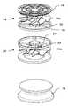
도 1은 제 1 실시예의 전체 구성을 나타내는 사시도이다.
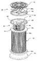
도 2는 제 1 실시예의 본체 케이싱을 제거한 구성을 나타내는 사시도이다.
도 3은 제 1 실시예의 본체 케이싱을 나타내는 사시도이다.
도 4는 제 1 실시예의 필터를 제거한 구성을 나타내는 사시도이다.
도 5은 제 1 실시예의 본체 케이싱 및 필터를 제거한 구성을 나타내는 사시도이다.
도 6은 제 2 실시예의 전체 구성을 나타내는 사시도이다.
도 7은 제 2 실시예의 본체 케이싱을 제거한 구성을 나타내는 사시도이다.
도 8은 제 2 실시예의 필터를 제거한 구성을 나타내는 사시도이다.
도 9는 제 2 실시예의 본체 케이싱 및 필터를 제거한 구성을 나타내는 사시도이다.
도 10a 및 도 10b는 셔터의 일례를 설치한 구성을 나타내는 도면이다.
도 11은 셔터가 형성되는 부위의 본체 케이싱의 구성을 나타내는 도면이다.
도 12a 및 도 12b는 셔터의 개폐 상태를 나타내는 도면이다.
도 13a 및 도 13b는 셔터의 다른 예를 나타내는 도면이다.
도 14는 셔터의 다른 예의 구성을 나타내는 도면이다.
도 15는 셔터가 형성되는 부위의 본체 케이싱의 구성을 나타내는 도면이다.
도 16은 셔터의 또 다른 예의 구성을 나타내는 도면이다.
도 17은 셔터의 또 다른 예의 구성을 나타내는 도면이다.
도 18은 팬이 이동하는 구성예를 나타내는 도면이다.
도 19는 필터에 외기를 통과시키며, 또한 통기구로부터 외기를 흡인하는 경우의 공기의 흐름을 나타내는 도면이다.
도 20은 통기구를 닫아 필터에 외기를 통과시키는 경우의 공기의 흐름을 나타내는 도면이다.Fig. 1 is a perspective view showing the entire configuration of the first embodiment. Fig.
Fig. 2 is a perspective view showing a configuration in which the main body casing of the first embodiment is removed. Fig.
3 is a perspective view showing the main body casing of the first embodiment.
4 is a perspective view showing the configuration of the filter of the first embodiment with the filter removed.
5 is a perspective view showing the structure of the main body casing and the filter of the first embodiment.
6 is a perspective view showing the entire configuration of the second embodiment.
Fig. 7 is a perspective view showing a configuration in which the main body casing of the second embodiment is removed.
Fig. 8 is a perspective view showing the configuration of the second embodiment with the filter removed. Fig.
Fig. 9 is a perspective view showing a configuration in which the main casing and the filter of the second embodiment are removed. Fig.
10A and 10B are views showing a configuration in which an example of a shutter is provided.
11 is a view showing a configuration of a main casing at a portion where a shutter is formed.
12A and 12B are views showing the shutter open / closed state.
13A and 13B are views showing another example of the shutter.
14 is a view showing the configuration of another example of the shutter.
Fig. 15 is a view showing a configuration of a main casing at a portion where a shutter is formed. Fig.
16 is a view showing a configuration of still another example of the shutter.
17 is a view showing the configuration of still another example of the shutter.
18 is a diagram showing an example of a configuration in which the fan moves.
19 is a view showing the flow of air in the case where outside air is passed through the filter and outside air is sucked from the vent hole.
20 is a view showing the flow of air when air is passed through the filter to close the air vent.
이하, 본 발명의 실시예에 대하여 도면에 기초하여 설명한다.Hereinafter, embodiments of the present invention will be described with reference to the drawings.
<제 1 실시예>≪ Embodiment 1 >
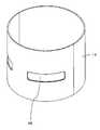
도 1은, 제 1 실시예에 따른 공기 청정 장치(10)의 전체 구성을 나타내는 사시도이며, 도 2는 본체 케이싱을 생략한 사시도, 도 3은 본체 케이싱을 나타내는 사시도이다. 여기서, 각 도면에 있어서, 본체 케이싱의 개구부에 부착하는 비교적 큰 티끌 등을 포집하는 망 형상 필터 등은 생략되어 있다.Fig. 1 is a perspective view showing the entire configuration of an
본체 케이싱(12)은 원통형이며, 하단은 받침대(14)에 부착되고, 상단에는 뚜껑(16)이 부착되어 있다.The
받침대(14)는, 하방을 향해 퍼지는 나팔 모양의 형상을 하고 있고, 하단이 마루 등에 안정되게 재치할 수 있게 되어 있다. 또한, 받침대(14)는, 본체를 지지할 수 있다면 어떠한 형상이어도 상관없다.The pedestal (14) has a trumpet shape extending downward, and the lower end can be stably mounted on a floor or the like. Further, the
받침대(14)의 상단에는, 원통형의 필터(18)가 부착된다. 필터(18)는, 공기를 통과시켜 여과하는 원통형의 필터부(18a), 하부 플랜지(18b)와, 상부 플랜지(18c)로 되어 있고, 하부 플랜지(18b)가 받침대(14)의 상부에 부착된다. 이 하부 플랜지(18b)는, 본체 케이싱(12)의 하단을 지지해도 좋으나, 받침대(14)의 상부에 원판을 설치하고, 이 원판에서 필터(18)의 하부 플랜지(18b) 및 본체 케이싱(12)의 하부를 지지해도 좋다.At the upper end of the
또한, 본 실시예에서는, 본체 케이싱(12), 필터(18)를 원통형으로 했으나, 다각 통 형상 등 다른 형상으로 하는 것도 바람직하다.In the present embodiment, the
필터(18)는, 하부 플랜지(18b), 상부 플랜지(18c) 모두 도너츠 형상이다. 필터부(18a)는, 예를 들면, 종이 또는 부직포 등으로 형성되고, 미립자를 외측 표면에 포착하여, 청정화한 공기를 내측에서 얻는다. 필터부(18a)는, 표면적을 넓히기 위해 오목부와 볼록부를 둘레 방향으로 반복되게 접어 구부러지고, 하단이 하부 플랜지(18b), 상단이 상부 플랜지(18c)에 기밀하게 부착되어 있다. 또한, 하부 플랜지(18b)의 개구는, 받침대(14)의 원판에 의해 닫혀져 있으나, 하부 플랜지(18b)를 대신하여 원판을 채용하여, 필터(18)의 내부 공간의 하방을 닫아도 좋다.The
필터(18)의 상부 플랜지(18c)의 주변은, 본체 케이싱(12)의 내면에 기밀하게 부착되고, 하부 플랜지(18b)의 주변 또는 받침대(14)의 상부 원판부가 본체 케이싱(12)의 내면에 기밀하게 부착된다. 따라서, 필터부(18a)의 내측 공간은, 상부 플랜지(18c)의 중앙 개구만으로 외부와 연통하고, 필터부(18a)의 외측과 필터부(18a)에 의해 구획되어 있다.The periphery of the
그리고, 필터부(18a)의 외측에 위치하는 본체 케이싱(12)에는, 복수의 개구부(12a)가 설치되어 있고, 필터부(18a)의 외측 공간은 외부 공간과 연통하고 있다.A plurality of
본체 케이싱(12) 내의 상부 플랜지(18c)의 상방에는, 필터용 팬(20)이 설치되어 있다. 이 필터용 팬(20)의 상방에는, 주변 링과 중심 원판을 가지고, 주변 링과 중심 원판 사이가 반경 방향의 복수의 연결대에 의해 연결된 스테이(22)가 배치되어 있다. 이 스테이(22)는, 주변 링이 본체 케이싱(12)의 내면에 고정되어 있기 때문에 본체 케이싱(12)에 고정되어 있다. 그리고, 스테이(22)의 중심 원판에는, 하방을 향해 모터(24)가 부착되고, 이 모터(24)로부터 하방으로 연장하는 회전축에 필터용 팬(20)의 날개(20a)가 부착되어 있다. 따라서, 모터(24)가 회전함으로써, 날개(20a)가 회전되어 필터용 팬(20)이 구동된다.A
날개(20a)는, 반경 방향으로 넓어지는 판 형상의 복수의 날개로 되어 있고, 필터용 팬(20)은 축류 타입의 팬으로 되어 있다.The
또한, 이 필터용 팬(20)이 배치되는 부분의 본체 케이싱(12)에는 개구가 없고, 필터용 팬(20)은 본체 케이싱(12)의 원통 내에 배치되어 있으므로, 필터용 팬(20)을 구동함으로써 본체 케이싱(12) 내의 공기를 상하 중 어느 한 방향으로 송풍할 수 있다.The
필터용 팬(20)의 상방, 즉, 스테이(22)보다 상방의 본체 케이싱(12)에는, 복수의 개구가 형성되고, 이것이 외부와 연통하는 통기구(26)로 되고 있다.A plurality of openings are formed in the
그리고, 이 통기구(26)의 상방의 본체 케이싱(12) 내에 배기용 팬(28)이 배치되어 있다. 즉, 통기구(26)의 상방에 스테이(22)와 같은 구성을 가지는 스테이(30)가 배치되고, 이 스테이(30)의 중앙 원판 상에 모터(32)가 부착되고, 이 모터(32)로부터 상방으로 연장하는 회전축에 배기용 팬(28)의 날개(28a)가 부착되어 있다. 따라서, 모터(32)가 회전함으로써 날개(28a)가 회전되고, 배기용 팬(28)이 구동된다. 배기용 팬(28)도 축류 타입의 팬이다.An
배기용 팬(28)의 주위의 본체 케이싱(12)은 닫혀 있고, 배기용 팬(28)에 의해 본체 케이싱(12) 내의 공기가 상방향 또는 하방향으로 송풍된다.The
본체 케이싱(12)의 상단은 개구되어 있고, 여기에 뚜껑(16)이 부착되어 있다. 이 뚜껑(16)은, 주변 링과, 중앙 원판과, 복수의 중간 링과, 이들을 연결하는 반경 방향의 연결대를 구비하고, 공기의 흐름은 거의 방해하지 않고, 사용자의 손 등이 본체 케이싱(12)의 내부에 들어가지 않게 하는 가이드로 되어 있다.The upper end of the
이와 같이, 본 실시예에서는, 필터(18)의 내부 공간과 연통하는 본체 케이싱(12) 내부에 필터용 팬(20)이 배치되어 있다. 따라서, 필터용 팬(20)에 의해, 필터(18)의 내부 공간을 배기함으로써, 외부의 공기가, 필터부(18a)를 통과하여 여과되고, 여과 후의 청정화된 공기가 필터용 팬(20)의 상방을 향해 송풍된다.As described above, in the present embodiment, the
또한, 배기용 팬(28)에 의해, 본체 케이싱(12) 내의 공기를, 뚜껑(16)을 거쳐 상방으로 배기함으로써, 필터용 팬(20)에 의해 배출되는 공기뿐만이 아니라, 통기구(26)를 거쳐 흡입된 공기가 상방을 향해 송풍된다.The
「청정화+순환 모드(제 2 모드)」"Purification + circulation mode (second mode)"
필터용 팬(20)과, 배기용 팬(28)의 송풍 능력을 동일하게 하고, 양자 모두 상방을 향해 송풍하면, 필터용 팬(20)에서는, 필터부(18a)의 압손(壓損)분만큼 송풍 능력을 줄일 수 있으므로, 배기용 팬(28)은, 통기구(26)로부터의 외기를 흡입하면서 상방을 향해 송풍하게 된다. 또한, 배기용 팬(28)의 송풍 능력을 필터용 팬(20)보다 크게 해도, 통기구(26)로부터 외기가 흡입되어 상방을 향해 송풍된다.When the blowing ability of the
이에 의해, 필터부(18a)를 통과한 청정화한 공기뿐만이 아니라, 통기구(26)로부터 흡입한 공기도 송풍할 수 있고, 공기 청정기의 상방을 향한 송풍량을 크게 할 수 있다. 따라서, 실내의 공기를 필터(18)에 의해 청정화하고, 또한 실내의 공기의 순환을 충분한 것으로 할 수 있다. 이에 의해, 공기 순환을 실시함으로써, 실내의 공기가 유동하여, 개구부(12a)의 주변뿐만이 아니라, 실내 전체의 공기를 필터(18)에 의해 청정화하는 것이 가능해진다.As a result, not only the cleaned air passing through the
또한, 필터용 팬(20)의 송풍 방향은, 상술한 경우와 같이 상향으로 하고, 배기용 팬(28)의 송풍 방향을 하향으로 하면, 필터용 팬(20)으로부터의 송풍 공기, 배기용 팬(28)의 송풍 공기가 하나가 되어 통기구(26)로부터 배출되게 된다. 이에 의해, 장치의 하방 및 상방으로부터의 공기를 흡입하여 통기구(26)로부터 대략 수평 방향으로 공기를 불어낼 수 있고, 필터(18)에 의한 공기 청정화와 실내 공기의 순환을 행할 수 있다.The blowing direction of the
배기용 팬(28)의 송풍 방향을 적절하게 반전함으로써, 실내 공기에 대해 복수의 방향의 순환을 행할 수 있고, 실내 공기 전체를 움직여서 청정화하는 것이 가능해진다.By properly reversing the air blowing direction of the
또한, 본체 케이싱(12)을 원통형으로 했으므로, 회전하는 팬에 의한 송풍 능력을 충분히 발휘시킬 수 있고, 또한 설치 면적을 작게 할 수 있다.Further, since the
「공기 순환 모드(제 2 모드)」"Air circulation mode (second mode)"
필터용 팬(20)을 정지하고, 배기용 팬(28)만을 구동하는 것에 의해, 공기 순환만이행해진다. 배기용 팬의 송풍 방향을 반전시킴으로써, 통기구(26)로부터 공기를 흡입하여 상방을 향해 배기하는 모드와, 상방으로부터 공기를 흡입하여 통기구(26)로부터 측방을 향해 배기하는 모드를 전환하여 사용할 수 있다.Only the air circulation is performed by stopping the
「청정화 모드(제 1 모드)」&Quot; Purification mode (first mode) "
배기용 팬(28)을 정지하고, 필터용 팬(20)만을 구동하는 것에 의해, 필터(18)를 통과한 공기가 상방을 향해 배출된다. 이 경우, 통기구(26)로부터도 공기는 배출되는 경우가 있으나, 대부분은 그대로 상방으로 빠져나가게 된다. 그리고, 상방으로 배출된 공기에 의해 실내의 공기가 순환되지만, 배기용 팬(28)이 구동되는 경우에 비해서 그 풍량은 적고, 공기 순환 기능은 비교적 작다. 또한, 배기용 팬(28)을 정지하는 것이 아니라, 그 풍량을 감소하는 것이어도 좋다.By stopping the
<제 2 실시예>≪ Embodiment 2 >
도 6 내지 도 9에 제 2 실시예의 구성을 나타낸다. 이 실시예에서는, 필터용 팬(20)으로서 원심 타입의 팬인 시록코 팬을 사용하고 있다. 즉, 이 필터용 팬(20)에서는, 위에서 보아 반경 방향으로부터 한 방향측으로 어긋난 판 형상의 다수의 날개(40)가 원통형으로 배치되어 있다. 그리고, 이 날개(40)의 원통의 상측은 상부 원판(42)에 고정되고, 이 상부 원판에 의해 닫혀져 있다. 한편, 날개(40)의 원통의 하측은, 도너츠 형상의 링(44)에 접속되어 있고, 이 링(44)이 필터(18)의 상부 플랜지(18c)의 내주에 회전 가능하게 지지되어 있다.6 to 9 show the configuration of the second embodiment. In this embodiment, a sirocco fan, which is a centrifugal type fan, is used as the
그리고, 스테이(22)는, 필터용 팬(20)의 상방에 있고, 이 스테이(22)의 중심부의 하측에 모터(24)가 부착되어 있다. 필터용 팬(20)의 상부 원판(42)은 중앙 부분이 하부를 향해 패여있고, 여기에 모터(24)의 일부가 수용된다. 또한, 모터(24)의 출력축이 상부 원판(42)의 중심에 고정되어 있다.The
상부 원판(42)의 직경은, 본체 케이싱(12)의 내경에 비해 작게 설정되어 있으므로, 원통형의 날개(40)의 주위 공간은, 본체 케이싱(12) 내에서 상방으로 연통하고 있으나, 원통형의 날개(40)의 하단에 있어서 상부 플랜지(18c)에 의해 닫혀져 있다. 한편, 필터부(18a)의 내부 공간과 원통형의 날개(40)의 내부 공간은, 링(44)의 중앙 개구에 의해 연통하고 있다.The diameter of the upper
따라서, 날개(40)를 소정 방향으로 회전하는 것에 의해, 날개(40)의 내부 공간의 공기가 주위 공간을 향해 보내지고, 본체 케이싱(12) 내를 상방을 향해 송풍된다. 따라서, 필터(18)에 의해 청정화된 공기가 필터용 팬(20)에 의해 본체 케이싱(12) 내를 상방을 향해 송풍된다.Therefore, by rotating the
여기서, 시록코 판 등의 원심 타입의 팬은, 축류 타입에 비해 흡입측과 배출측의 압력차를 크게 할 수 있다. 여기서, 필터용 팬(20)을 원심 타입, 배기용 팬(28)을 축류 타입으로 함으로써, 필터(18)에 의한 압손을 고려하여, 효율적인 여과 처리를 행할 수 있고, 배기용 팬(28)에 의해 통기구(26)를 이용하여 효율적인 송풍을 행할 수 있다.Here, the centrifugal type fan such as a sirocco fan can increase the pressure difference between the suction side and the discharge side as compared with the axial flow type. The
이와 같이, 2 개의 팬의 특성을 다르게 함으로써, 전체적으로 효율적인 공기 청정화 및 공기 순환을 행할 수 있다.By thus changing the characteristics of the two fans, efficient air purification and air circulation can be performed as a whole.
<셔터><Shutter>
여기서, 도 10a 내지 도 12b에는, 통기구(26)에 셔터(50)를 설치한 구성예가 도시되어 있다. 이 예에서는, 도 11에 도시한 본체 케이싱(12)의 통기구(26)가 설치되어 있는 부분의 내측에 상하 방향 및 반경 방향으로 이동하는 셔터(50)가 배치되고, 이 셔터(50)에 의해 통기구(26)를 개폐한다.Here, Figs. 10A to 12B show a configuration example in which the
본체 케이싱(12)에 내측에 스테이(52)가 부착되고, 이 스테이(52)의 중앙 부분에는, 모터(54)가 부착되고, 이 모터(54)에 의해 피니언 기어(56)가 회전된다. 피니언 기어(56)에는 락(58)이 맞물려져 있고, 피니언 기어(56)가 정역 방향으로 회전함으로써 락(58)이 상하 방향으로 이동한다.A
락(58)의 하단은, 원통형의 중심 부재(60)에 접속되어 있고, 이 중심 부재로부터 반경 방향으로 성장하는 연결재(62)에 통기구(26)의 형태에 대응한 덮개 부재(64)가 부착되어 있다.The lower end of the
여기서, 덮개 부재(64)는, 연결재(62)에 대해, 반경 방향으로 이동 가능하게 부착되어 있으며, 또한 그 양측에 설치된 핀(66)이 본체 케이싱(10)의 통기구(26)의 원주 방향 양측에 해당되는 부분에 설치된 가이드홈(68)에 계합되어 있다. 그리고, 가이드홈(68)은, 핀(66)의 하부로의 이동에 따라 핀이 본체 케이싱(10)의 내측으로 이동하도록 형성되어 있다. 따라서, 연결 부재(62)의 상하 방향의 이동에 따라, 덮개 부재(64)는 상하 방향으로 이동할 뿐만 아니라, 반경 방향으로도 이동한다.Here, the
즉, 도 12a 및 도 12b에 도시한 바와 같이, 덮개 부재(64)가 상단에 위치하는 경우에는, 덮개 부재(64)는 반경 방향의 외측에 위치하고, 통기구(26)에 꽉 눌려져 통기구(26)을 닫는다. 한편, 덮개 부재(64)가 하부로 이동하면, 가이드홈(68)에 가이드되고, 덮개 부재(64)는 통기구(26)로부터 내측으로 인입되어, 본체 케이싱(12) 내에 수용된다.12A and 12B, when the
이와 같이 하여, 모터(54)의 정역 회전에 의해, 덮개 부재(64)에 의해 통기구(26)를 닫거나 개방할 수 있다.In this manner, the
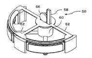
도 13a 내지 도 15에는, 셔터(50)의 다른 구성예가 도시되어 있다. 이 예에서는, 도 15에 도시한 본체 케이싱(12)의 통기구(26)가 설치되어 있는 부분의 내측에 원주 방향으로 이동하는 셔터(50)가 배치되고, 이 셔터(50)에 의해 통기구(26)를 개폐한다.13A to 15 show another example of the configuration of the
본체 케이싱(12)에 내측에 스테이(52)가 부착되고, 이 스테이(52)의 중앙 부분에는, 모터(54)에 의해 수평면 내에서 회전되는 회전 원판(70)이 설치되어 있고, 이 회전 원판(70)의 하면에 편심하여 핀(도시하지 않음)이 부착되어 있다.A
그리고, 도 14에 도시한 바와 같이, 이 회전 원판(70)의 하면의 편심한 위치에 핀(도시하지 않음)이 돌출 형성되어 있다. 따라서, 이 회전 원판(70)의 핀이 모터(54)의 회전에 의해 선회 운동을 한다.As shown in Fig. 14, a pin (not shown) is formed at an eccentric position on the lower surface of the
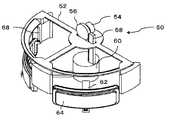
회전 원판(70)의 아래에는 가이드 바(72)가 설치되고, 이 가이드 바(72)의 긴 홀(74)에 회전 원판(70)의 핀이 계합한다. 또한, 가이드 바(72)의 하부에는, 회동 원통(76)이 설치되어 있고, 이 회동 원통(76)의 상단에는, 중심 방향을 향하는 복수의 연결재(78)와, 이 연결재의 내측에 접속된 중심부(80)가 형성되고, 회동 원통(76)의 주변 원통부(82)에는, 복수의 창(84)이 설치되어 있다.A
이 창(84)은, 본체 케이싱(10)의 통기구(26)에 대응한 형상으로 되어 있고, 회동 원통(76)이 회동함에 의해 통기구(26)가 개폐된다.This
그리고, 가이드 바(72)의 일단측의 하면에는, 핀이 형성되어 있고, 이 핀이 중심부(80)에 편심하여 설치된 홀(80a)과 계합한다. 따라서, 회전 원판(70)의 핀이 긴 홀(74) 중에서 이동하고, 여기에 따른 가이드 바(72)의 회동이 홀(80a)을 거쳐, 회동 원통(76)의 왕복 회전 운동으로 변환된다(도 13a 및 도 13b 참조). 이 회동 원통(76)의 왕복 회동량을 통기구(26)의 개폐에 대응함으로써, 모터(54)의 회전에 의해, 통기구(26)의 개폐가 가능해진다.A pin is formed on the lower surface of one end of the
또한, 도 15에 도시한 바와 같이, 통기구(26)를 본체 케이싱(10)의 원주 방향의 반에만 설치했다. 이에 의해, 통기구(26)로부터 흡입하는 공기의 방향을 한정할 수 있으나, 통기구(26)를 전면에 설치하여 회동 원통(76)에 설치하는 창(84)도 대응하여 전면에 설치해도 좋다.Further, as shown in Fig. 15, the ventilation holes 26 are provided only in the half of the circumferential direction of the
여기서, 셔터(50)를 사용자가 손으로 조작하여 모드를 전환해도 좋다.Here, the
이와 같이, 셔터(50)에 의해, 통기구(26)를 개폐함으로써, 배기용 팬(28)의 기능을 필터(18)에 의한 여과를 위한 것과, 공기 순환을 주된 기능으로 하는 것의 양쪽 모두로 전환할 수 있다.By thus opening and closing the
또한, 도 16에 도시한 바와 같이, 통기구(26)를 설치하지 않고, 필터부(18)의 외부 공간과 배기용 팬(28)을 수용하는 공간을 연통하는 바이패스(56)를 설치하고, 이 바이패스(56)를 개폐하는 셔터(50)를 설치해도 좋다. 이 예에서는, 바이패스(56)는, 파이프 형상으로, 필터부(18)의 외부 공간으로부터 필터용 팬(20)의 상방 공간에까지 연장되어 있다. 그리고, 이 바이패스(56)의 상단 개구를 개폐하는 셔터(50)를 설치하고 있다. 셔터(50)는 링 형상이며 바이패스(56)에 대응한 수의 개구를 가지고, 원주 방향으로 이동함으로써 바이패스(56)의 상단 개구를 개폐한다.16, a
이에 의해, 바이패스(56)를 개폐할 수 있고, 배기용 팬(28)에 의한 송풍을 필터(18)의 내측 공간으로부터인지, 외측 공간(외부)으로부터인지를 전환할 수 있다.As a result, the
또한, 바이패스(56)는, 필터부(18a)의 내측 공간을 연장하여 필터부(18a)를 관통하여, 외측 공간에 연통하도록 해도 좋다.The
도 17에는, 또한 변형예가 도시되어 있다. 이 예에서는, 도 14의 예와 비교하여, 팬이 필터용 팬(20)이 1 개 밖에 없다. 그리고, 필터(18)의 상부 플랜지(18c)의 주위에 필터부(18a)의 외부 공간과 연통하는 개구(80)를 설치하고, 이 개구(80)를 개폐하는 셔터(50)를 설치하고 있다. 이에 의해, 개구(80)를 개폐할 수 있고, 필터용 팬(20)에 의한 송풍을 필터(18)의 내측 공간으로부터인지, 외측 공간(외부)으로부터인지를 전환할 수 있다. 또한, 이 경우도 개구(80)가 연통하는 통로를 필터부(18a)의 내측 공간을 연장하고, 필터부(18a)를 관통하여, 외측 공간에 연통하도록 해도 좋다.In Fig. 17, a modification is also shown. In this example, as compared with the example of Fig. 14, there is only one
도 18에는, 또 다른 예를 도시하고 있다. 이 예에서는, 배기용 팬(28)이 상하 이동한다. 즉, 배기용 팬(28)이 통기구(26)의 상부와 하부의 두 위치로 이동 가능하도록 되어 있다. 이에 의해, 배기용 팬(28)이 통기구(26)의 하부에 있는 경우에, 배기용 팬(28)은 필터부(18)의 내부 공간으로부터의 공기를 흡입하여 상방으로 송풍하고, 배기용 팬(28)이 통기구(26)의 상방에 위치하는 경우에, 배기용 팬(28)은 통기구(26)로부터 흡입한 외기를 상방으로 송풍한다.Fig. 18 shows another example. In this example, the
또한, 이 예에서는, 필터용 팬(20)을 생략하고 있으나, 필터용 팬(20)을 설치하고, 필터용 팬(20)은 상술한 실시예와 같이 필터부(18a)의 내부 공간으로부터의 공기를 배출하도록 하면 좋다.In this example, the
<공기의 흐름><Air flow>
도 19에는, 배기용 팬(28)에 있어서, 통기구(26)로부터의 외기를 흡입하는 모드에서의 공기의 흐름을 도시하고 있다. 이와 같이, 필터용 팬(20)에 의해, 필터(18)의 내부 공간의 공기를 상방을 향해 송풍함으로써, 외기가 개구부(12a)를 거쳐, 필터(18)를 통과하고, 청정화된 공기가 상방을 향해 송풍된다. 또한, 배기용 팬(28)에 의해, 통기구(26)로부터 외기가 흡입되어, 이들이 합쳐진 공기가 상방을 향해 송풍된다.Fig. 19 shows the flow of air in the mode for sucking outside air from the
도 20에는, 통기구(26)를 셔터(50)에 의해 닫은 경우의 공기의 흐름을 나타내고 있다. 이와 같이, 필터용 팬(20), 배기용 팬(28)에 의해 필터(18)를 통과한 청정화 공기가 상방을 향해 송풍된다. 이와 같이, 두 개의 팬에 의해 송풍하므로, 필터(18)를 통과하여 청정화되는 공기량을 증가하는 것이 가능하게 된다.Fig. 20 shows the flow of air when the
<기타><Others>
상술한 예에서는, 셔터(50)는, 본체 케이싱(12)에 설치한 통기구를 내측으로부터 개폐하도록 구성했다. 그러나, 통기구(26)를 본체 케이싱(12)의 외측으로부터 개폐하도록 구성해도 좋다. 또한, 바이패스(56)를 본체 케이싱(12) 내에 배치했으나, 이것도 본체 케이싱(12)의 외측에 배치할 수도 있다.In the above-described example, the
제어 장치에 의해 각종 모드를 자동적으로 전환할 수 있다. 예를 들면, 10 분 간격 등, 정기적으로 공기 순환을 강하게 하거나, 각종 센서의 출력 신호에 의해, 공기 순환 모드 또는 공기 청정 모드를 새로 바꿀 수도 있다. 예를 들면, 상방 하부의 온도차가 큰 때에 공기 순환을 실시하거나, 공기 중의 미립자량을 검출하여, 미립자량이 많았던 경우에, 공기 청정을 강하게 하거나 할 수 있다.Various modes can be automatically switched by the control device. For example, the air circulation can be strengthened regularly at intervals of 10 minutes, or the air circulation mode or the air cleaning mode can be newly changed by the output signals of various sensors. For example, the air circulation can be performed when the temperature difference between the upper and lower portions is large, or the amount of the fine particles in the air can be detected, and the air cleaning can be strengthened when the amount of fine particles is large.
도시를 생략하였으나, 필터용 팬(20), 배기용 팬(28)을 구동하는 모터(24, 32)에는, 직류 모터가 채용된다. 여기서, 통상 교류 100V의 상용 전력을 직류로 변환한 직류 전력을 공급하여 구동한다. 또한, 모터(24, 32)를 교류 모터로 하여 교류 전력을 그대로 공급해도 좋다. 또한, 마이크로 컴퓨터 등의 제어부를 설치하고, 이에 의해 모터의 구동 제어를 실시하면 좋다.A DC motor is employed as the
또한, 상기 실시예에서는, 필터용 팬(20)과 배기용 팬(28)을 1 개씩 설치했으나, 필터용 팬(20) 또는 배기용 팬(28)의 어느 하나를 복수로 하거나, 양쪽 모두를 복수로 해도 상관없다. 이와 같이 함으로써, 송풍량에 대한 자유도를 향상할 수 있다.Although the
<실시예의 효과>≪ Effect of Embodiment >
본 실시예에 의하면, 다음과 같은 효과를 얻을 수 있다.According to the present embodiment, the following effects can be obtained.
(i) 필터를 통한 청정화 공기뿐만이 아니라, 외기를 흡입하여, 이를 송풍할 수 있다. 이에 의해, 송풍량을 크게 할 수 있고, 실내의 공기를 순환할 수 있다. 그리고, 공기 순환을 실시함으로써, 실내의 공기 전체를 청정화할 수 있다.(i) Not only the purified air through the filter, but also the outside air can be sucked and blown. As a result, the air blowing amount can be increased and the air in the room can be circulated. By performing the air circulation, the entire air in the room can be cleaned.
(ii) 2 개의 팬을 설치하고, 이들을 독립하여 제어함으로써, 각종 모드에서의 운전이 가능하게 된다.(ii) Two fans are provided, and these are independently controlled, so that operation in various modes becomes possible.
(iii) 셔터를 설치함으로써, 확실한 모드 전환이 행해지고, 공기 청정 능력도 전환할 수 있다.(iii) By providing a shutter, reliable mode switching is performed, and the air cleaning ability can be switched.
10 공기 청정 장치
12 본체 케이싱
12a 개구부
14 받침대
16 뚜껑
18 필터
18a 필터부
18b 하부 플랜지
18c 상부 플랜지
20 필터용 팬
20a, 28a, 40 날개
22, 30 스테이
24 모터
26 통기구
28 배기용 팬
32 모터
42 상부 원판
44 링
50 셔터
52 스테이
56 바이패스10 Air Cleaner
12 Body casing
12a opening
14 Base
16 Lid
18 filter
18a filter portion
18b Lower flange
18c upper flange
20 Fans for filters
20a, 28a, 40 wing
22, 30 stay
24 motors
26 Vents
28 Exhaust fan
32 motors
42 Upper disc
44 ring
50 Shutter
52stays
56 Bypass
Claims (7)
Translated fromKorean이 본체 케이싱 내에 배치되고, 상기 공기 유통로를 필터의 상류측과 하류측으로 나누는 필터와,
상기 공기 유통로의 하류측에 설치되고, 상기 공기 유통로의 하류측의 공기를 상기 배출구로부터 배출하는 배기용 팬과,
상기 배기용 팬과 상기 필터의 사이의 상기 공기 유통로와 외부를 연통하는 연통 수단을 포함하고,
상기 연통 수단에 의해, 상기 필터의 하류측의 공기 유통로와 외부와의 사이의 공기의 유통이 가능한 공기 청정 장치.A main casing having a suction port on one side and a discharge port on one side and an air flow passage formed therein,
A filter disposed in the main body casing and dividing the air flow passage into an upstream side and a downstream side of the filter,
An exhaust fan provided on the downstream side of the air flow passage for discharging air on the downstream side of the air flow passage from the discharge port,
And communication means for communicating with the outside of the air flow path between the exhaust fan and the filter,
Wherein the communication means allows the air to flow between the air flow passage on the downstream side of the filter and the outside.
상기 공기 유통로의 하류측의 배출구측이며, 상기 연통 수단에 의한 연통 개소로부터 상기 필터측에 설치된, 필터를 통과한 공기를 흡입하기 위한 필터용 팬을 포함한 공기 청정 장치.The method according to claim 1,
And a filter fan for sucking air having passed through the filter, the filter being provided on the filter side from a communicating portion by the communicating means on the downstream side of the air flow passage.
상기 필터용 팬은 원심 타입, 배기용 팬은 축류 타입의 팬인 공기 청정 장치.3. The method of claim 2,
Wherein the fan for the filter is a centrifugal type and the fan for exhausting is a fan of an axial flow type.
상기 필터용 팬과, 상기 배기용 팬을, 독립하여 구동 제어하는 구동 제어부를 포함한 공기 청정 장치.3. The method of claim 2,
And a drive control section for independently controlling driving of said filter fan and said exhaust fan.
상기 필터용 팬은 원심 타입, 배기용 팬은 축류 타입의 팬인 공기 청정 장치.5. The method of claim 4,
Wherein the fan for the filter is a centrifugal type and the fan for exhausting is a fan of an axial flow type.
상기 연통 수단은, 상기 본체 케이싱에 설치되고, 상기 공기 유통로와 외부를 연통하는 통기구인 것을 특징으로 하는 공기 청정 장치.6. The method according to any one of claims 1 to 5,
Wherein the communication means is an air vent provided in the main body casing and communicating with the outside of the air flow passage.
상기 통기구는 개폐 가능한 것을 특징으로 하는 공기 청정 장치.
The method according to claim 6,
Wherein the air vent is openable and closable.
Applications Claiming Priority (3)
| Application Number | Priority Date | Filing Date | Title |
|---|---|---|---|
| JPJP-P-2012-088816 | 2012-04-09 | ||
| JP2012088816AJP5864344B2 (en) | 2012-04-09 | 2012-04-09 | Air purifier |
| PCT/JP2013/060121WO2013153995A1 (en) | 2012-04-09 | 2013-04-02 | Air-cleaning device |
Publications (2)
| Publication Number | Publication Date |
|---|---|
| KR20150005594Atrue KR20150005594A (en) | 2015-01-14 |
| KR101705286B1 KR101705286B1 (en) | 2017-02-09 |
Family
ID=49327563
Family Applications (1)
| Application Number | Title | Priority Date | Filing Date |
|---|---|---|---|
| KR1020147031260AExpired - Fee RelatedKR101705286B1 (en) | 2012-04-09 | 2013-04-02 | Air-cleaning device |
Country Status (5)
| Country | Link |
|---|---|
| EP (1) | EP2837897B1 (en) |
| JP (1) | JP5864344B2 (en) |
| KR (1) | KR101705286B1 (en) |
| CN (1) | CN104204683B (en) |
| WO (1) | WO2013153995A1 (en) |
Cited By (25)
| Publication number | Priority date | Publication date | Assignee | Title |
|---|---|---|---|---|
| WO2017026761A1 (en)* | 2015-08-12 | 2017-02-16 | 코웨이 주식회사 | Air purifier |
| WO2017146352A1 (en)* | 2016-02-26 | 2017-08-31 | 엘지전자 주식회사 | Air cleaner |
| KR20170101093A (en)* | 2016-02-26 | 2017-09-05 | 엘지전자 주식회사 | Air cleaning apparatus |
| US9821259B2 (en) | 2016-02-26 | 2017-11-21 | Lg Electronics Inc. | Air cleaner |
| US9821262B2 (en) | 2016-02-26 | 2017-11-21 | Lg Electronics Inc. | Air cleaner and method for controlling an air cleaner |
| US9827523B2 (en) | 2016-02-26 | 2017-11-28 | Lg Electronics Inc. | Air cleaner |
| US9914082B2 (en) | 2016-02-26 | 2018-03-13 | Lg Electronics Inc. | Air cleaner |
| US9943794B2 (en) | 2016-02-26 | 2018-04-17 | Lg Electronics Inc. | Air cleaner |
| KR20180044131A (en)* | 2016-10-21 | 2018-05-02 | 엘지전자 주식회사 | Air cleaning apparatus |
| KR101876223B1 (en)* | 2013-12-27 | 2018-07-10 | 코웨이 주식회사 | Humidification type air cleaner |
| US10323855B2 (en) | 2016-02-26 | 2019-06-18 | Lg Electronics Inc. | Air cleaner |
| KR20190092365A (en)* | 2019-07-31 | 2019-08-07 | 엘지전자 주식회사 | Air cleaning apparatus |
| KR20190093537A (en)* | 2019-07-31 | 2019-08-09 | 엘지전자 주식회사 | Air cleaning apparatus |
| KR20190100142A (en)* | 2019-08-20 | 2019-08-28 | 엘지전자 주식회사 | Air cleaning apparatus |
| KR20190100143A (en)* | 2019-08-20 | 2019-08-28 | 엘지전자 주식회사 | Air cleaning apparatus |
| US10436469B2 (en) | 2016-02-26 | 2019-10-08 | Lg Electronics Inc. | Air cleaner |
| KR20190124680A (en)* | 2019-08-20 | 2019-11-05 | 엘지전자 주식회사 | Air cleaning apparatus |
| KR20190124683A (en)* | 2019-08-20 | 2019-11-05 | 엘지전자 주식회사 | Air cleaning apparatus |
| US10495104B2 (en) | 2016-02-26 | 2019-12-03 | Lg Electronics Inc. | Air cleaner |
| US10518205B2 (en) | 2016-02-26 | 2019-12-31 | Lg Electronics Inc. | Air cleaner |
| US10688431B2 (en) | 2015-04-09 | 2020-06-23 | Coway Co., Ltd. | Air purifier |
| US10697665B2 (en) | 2016-02-26 | 2020-06-30 | Lg Electronics Inc. | Air cleaner |
| US10888809B2 (en) | 2017-04-24 | 2021-01-12 | Blueair Ab | Foldable air filter unit |
| KR102259561B1 (en)* | 2020-11-10 | 2021-06-02 | (주)아지즈 | Air purifier with ventilation function |
| US11938433B2 (en) | 2016-02-26 | 2024-03-26 | Lg Electronics Inc. | Air cleaner |
Families Citing this family (36)
| Publication number | Priority date | Publication date | Assignee | Title |
|---|---|---|---|---|
| US20170082305A1 (en)* | 2014-03-17 | 2017-03-23 | Sui Chun Law | An Air Purification Device |
| JP6327643B2 (en)* | 2014-07-02 | 2018-05-23 | フルタ電機株式会社 | Particulate diffusion device |
| WO2016004399A1 (en)* | 2014-07-02 | 2016-01-07 | Free Air, Inc. | Room air cleaner systems and methods related thereto |
| JP2016034602A (en)* | 2014-08-01 | 2016-03-17 | バルミューダ株式会社 | Air cleaner |
| CN104296259A (en)* | 2014-10-17 | 2015-01-21 | 太仓市大友空调设备有限公司 | Appearance-variable multifunctional purifier |
| CN104406239A (en)* | 2014-12-17 | 2015-03-11 | 贵州黔唐电器有限责任公司 | Intelligent multifunctional air purifier |
| KR102396592B1 (en)* | 2014-12-22 | 2022-05-13 | 코웨이 주식회사 | Rapid cycling air conditioner |
| KR102359202B1 (en) | 2014-12-30 | 2022-02-07 | 삼성전자주식회사 | Air cleaner and home appliances including air handling unit |
| CN105221452A (en) | 2015-09-29 | 2016-01-06 | 小米科技有限责任公司 | Air cleaner and blast device thereof |
| CN206347652U (en)* | 2016-02-26 | 2017-07-21 | Lg电子株式会社 | Air purifier |
| JP6700409B2 (en)* | 2016-02-26 | 2020-05-27 | エルジー エレクトロニクス インコーポレイティド | Air cleaner |
| JP6777753B2 (en)* | 2016-02-26 | 2020-10-28 | エルジー エレクトロニクス インコーポレイティド | Air cleaner |
| AT14956U3 (en)* | 2016-03-03 | 2017-05-15 | Kluge Anton | Column-shaped advertising medium |
| KR102665025B1 (en) | 2016-08-19 | 2024-05-13 | 삼성전자주식회사 | Air cleaner |
| KR20180023235A (en)* | 2016-08-25 | 2018-03-07 | 엘지전자 주식회사 | Dryer and method for controlling the same |
| CN106225207A (en)* | 2016-09-18 | 2016-12-14 | 上海唤维信息科技有限公司 | A kind of can control the cleaning system of air flow path in space |
| EP3306218A1 (en)* | 2016-10-06 | 2018-04-11 | Unilever N.V. | Air purifier |
| CN106287993B (en)* | 2016-10-24 | 2021-01-26 | 北京小米移动软件有限公司 | Air purifier and air duct structure thereof |
| FR3081729B1 (en)* | 2018-05-29 | 2022-04-29 | Delta Neu | TRANSPORTABLE FILTRATION DEVICE |
| WO2020079789A1 (en)* | 2018-10-17 | 2020-04-23 | バルミューダ株式会社 | Air cleaning apparatus |
| WO2020079790A1 (en)* | 2018-10-17 | 2020-04-23 | バルミューダ株式会社 | Air cleaning device |
| KR102129528B1 (en)* | 2018-12-04 | 2020-07-08 | 주식회사 아지즈 | Air-changeable Ventilation Cleaner |
| JP7174296B2 (en)* | 2019-03-01 | 2022-11-17 | ダイキン工業株式会社 | Indoor air treatment device and its operation method |
| WO2020179687A1 (en)* | 2019-03-01 | 2020-09-10 | ダイキン工業株式会社 | Air cleaning and ventilation device |
| CN112007451B (en)* | 2019-05-31 | 2024-03-29 | 大金工业株式会社 | Air purifying device |
| WO2020183405A1 (en)* | 2019-03-12 | 2020-09-17 | Milind Dhanlal Raut | Centrifugal gas filtration apparatus |
| KR20210003623A (en) | 2019-07-02 | 2021-01-12 | 코웨이 주식회사 | Air Cleaner |
| JP6724220B1 (en)* | 2019-08-05 | 2020-07-15 | 株式会社ニトリホールディングス | Air purifier |
| CN110935250A (en)* | 2019-12-10 | 2020-03-31 | 科沃斯机器人股份有限公司 | Air purification equipment |
| KR20210083501A (en)* | 2019-12-27 | 2021-07-07 | 삼성전자주식회사 | Air cleaner |
| CN111412569B (en)* | 2020-04-01 | 2021-01-29 | 青岛理工大学 | A kind of ventilation and ventilation device for indoor air purification in buildings |
| JP2022170496A (en)* | 2021-04-28 | 2022-11-10 | ブラザー工業株式会社 | Air cleaner |
| KR102338380B1 (en) | 2021-06-02 | 2021-12-13 | 에이치케이시스템 | Wet type multifunctional air filter |
| CN113280456B (en)* | 2021-06-23 | 2023-11-10 | 合肥河姆博人工环境科技有限公司 | High-efficient water conservancy diversion formula plasma air disinfection purifier |
| JP2025120051A (en)* | 2024-02-02 | 2025-08-15 | Next Innovation合同会社 | Toxic target reduction device |
| CN118788714B (en)* | 2024-09-10 | 2024-11-29 | 南通娜秋纺织有限公司 | A textile dust collecting and cleaning device for a textile machine and a process thereof |
Citations (6)
| Publication number | Priority date | Publication date | Assignee | Title |
|---|---|---|---|---|
| JPH03128021A (en)* | 1989-10-13 | 1991-05-31 | Asmo Co Ltd | Vacuum cleaner |
| JP2000018657A (en) | 1998-06-30 | 2000-01-18 | Daikin Ind Ltd | Locally clean air purifier |
| KR200344684Y1 (en)* | 2003-12-19 | 2004-03-18 | 주식회사 디에스테크 | Apparatus for cleaning an indoor air with supplying an outdoor air |
| KR200382452Y1 (en)* | 2004-12-15 | 2005-04-20 | 주식회사 경남알미늄 | Ventilation device with heat exchanger installed in a window frame |
| JP2006292251A (en) | 2005-04-08 | 2006-10-26 | Matsushita Electric Ind Co Ltd | Ventilation equipment |
| KR20120040227A (en)* | 2009-07-29 | 2012-04-26 | 뉴폼 테크아트 피티이 리미티드 | Air filter |
Family Cites Families (7)
| Publication number | Priority date | Publication date | Assignee | Title |
|---|---|---|---|---|
| JPS60123521U (en)* | 1984-01-30 | 1985-08-20 | 株式会社日立製作所 | Air cleaner |
| JPH0621720U (en)* | 1992-06-26 | 1994-03-22 | ティアック株式会社 | Air purifier |
| JP3929278B2 (en)* | 2001-10-17 | 2007-06-13 | 株式会社フジシールインターナショナル | Film insertion device |
| US20030150326A1 (en)* | 2002-02-11 | 2003-08-14 | Hp Intellectual Corp. | Multi-stage air cleaner fan system |
| JP4630703B2 (en)* | 2005-03-29 | 2011-02-09 | シャープ株式会社 | Air cleaner |
| JP4978644B2 (en)* | 2009-03-06 | 2012-07-18 | 三菱電機株式会社 | Air treatment equipment |
| DE102009053505A1 (en)* | 2009-11-16 | 2011-05-19 | Wu, Fu-Chi, Northridge | Air cleaner, has fan controlled to pass outside air to air outlet such that low pressure is produced around space below housing and high pressure is produced around space above housing, so that convection of air takes place |
- 2012
- 2012-04-09JPJP2012088816Apatent/JP5864344B2/ennot_activeExpired - Fee Related
- 2013
- 2013-04-02KRKR1020147031260Apatent/KR101705286B1/ennot_activeExpired - Fee Related
- 2013-04-02CNCN201380019070.5Apatent/CN104204683B/ennot_activeExpired - Fee Related
- 2013-04-02WOPCT/JP2013/060121patent/WO2013153995A1/enactiveApplication Filing
- 2013-04-02EPEP13775667.2Apatent/EP2837897B1/ennot_activeNot-in-force
Patent Citations (6)
| Publication number | Priority date | Publication date | Assignee | Title |
|---|---|---|---|---|
| JPH03128021A (en)* | 1989-10-13 | 1991-05-31 | Asmo Co Ltd | Vacuum cleaner |
| JP2000018657A (en) | 1998-06-30 | 2000-01-18 | Daikin Ind Ltd | Locally clean air purifier |
| KR200344684Y1 (en)* | 2003-12-19 | 2004-03-18 | 주식회사 디에스테크 | Apparatus for cleaning an indoor air with supplying an outdoor air |
| KR200382452Y1 (en)* | 2004-12-15 | 2005-04-20 | 주식회사 경남알미늄 | Ventilation device with heat exchanger installed in a window frame |
| JP2006292251A (en) | 2005-04-08 | 2006-10-26 | Matsushita Electric Ind Co Ltd | Ventilation equipment |
| KR20120040227A (en)* | 2009-07-29 | 2012-04-26 | 뉴폼 테크아트 피티이 리미티드 | Air filter |
Cited By (50)
| Publication number | Priority date | Publication date | Assignee | Title |
|---|---|---|---|---|
| KR101876223B1 (en)* | 2013-12-27 | 2018-07-10 | 코웨이 주식회사 | Humidification type air cleaner |
| US10688431B2 (en) | 2015-04-09 | 2020-06-23 | Coway Co., Ltd. | Air purifier |
| US11666848B2 (en) | 2015-08-12 | 2023-06-06 | Coway Co., Ltd. | Air purifier with hinged filter frame |
| US11654388B2 (en) | 2015-08-12 | 2023-05-23 | Coway Co., Ltd. | Air purifier with hinged filter frame |
| US11654387B2 (en) | 2015-08-12 | 2023-05-23 | Coway Co., Ltd. | Air purifier with hinged filter frame |
| US11007467B2 (en) | 2015-08-12 | 2021-05-18 | Coway Co., Ltd. | Air purifier with hinged filter frame |
| US11007466B2 (en) | 2015-08-12 | 2021-05-18 | Coway Co., Ltd. | Air purifier with hinged filter frame |
| US10918984B2 (en) | 2015-08-12 | 2021-02-16 | Coway Co., Ltd. | Air purifier with hinged filter frame |
| US10821389B2 (en) | 2015-08-12 | 2020-11-03 | Coway Co., Ltd. | Air purifier with hinged filter frame |
| WO2017026761A1 (en)* | 2015-08-12 | 2017-02-16 | 코웨이 주식회사 | Air purifier |
| US10323855B2 (en) | 2016-02-26 | 2019-06-18 | Lg Electronics Inc. | Air cleaner |
| US9821262B2 (en) | 2016-02-26 | 2017-11-21 | Lg Electronics Inc. | Air cleaner and method for controlling an air cleaner |
| US11982288B2 (en) | 2016-02-26 | 2024-05-14 | Lg Electronics Inc. | Air cleaner |
| US11938433B2 (en) | 2016-02-26 | 2024-03-26 | Lg Electronics Inc. | Air cleaner |
| US11905967B2 (en) | 2016-02-26 | 2024-02-20 | Lg Electronics Inc. | Air cleaner |
| US11761455B2 (en) | 2016-02-26 | 2023-09-19 | Lg Electronics Inc. | Air cleaner |
| WO2017146352A1 (en)* | 2016-02-26 | 2017-08-31 | 엘지전자 주식회사 | Air cleaner |
| US10406470B2 (en) | 2016-02-26 | 2019-09-10 | Lg Electronics Inc. | Air cleaner |
| US10413857B2 (en) | 2016-02-26 | 2019-09-17 | Lg Electronics Inc. | Air cleaner |
| US10436469B2 (en) | 2016-02-26 | 2019-10-08 | Lg Electronics Inc. | Air cleaner |
| US11666846B2 (en) | 2016-02-26 | 2023-06-06 | Lg Electronics Inc. | Air cleaner |
| KR20170101093A (en)* | 2016-02-26 | 2017-09-05 | 엘지전자 주식회사 | Air cleaning apparatus |
| US10495104B2 (en) | 2016-02-26 | 2019-12-03 | Lg Electronics Inc. | Air cleaner |
| US10508658B2 (en) | 2016-02-26 | 2019-12-17 | Lg Electronics Inc. | Air cleaner |
| US10518205B2 (en) | 2016-02-26 | 2019-12-31 | Lg Electronics Inc. | Air cleaner |
| US10563667B2 (en) | 2016-02-26 | 2020-02-18 | Lg Electronics Inc. | Air cleaner |
| US10639576B2 (en) | 2016-02-26 | 2020-05-05 | Lg Electronics Inc. | Air cleaner |
| US10646808B2 (en) | 2016-02-26 | 2020-05-12 | Lg Electronics Inc. | Air cleaner |
| US10675577B2 (en) | 2016-02-26 | 2020-06-09 | Lg Electronics Inc. | Air cleaner |
| US9950289B2 (en) | 2016-02-26 | 2018-04-24 | Lg Electronics Inc. | Air cleaner |
| US10697665B2 (en) | 2016-02-26 | 2020-06-30 | Lg Electronics Inc. | Air cleaner |
| US10746193B2 (en) | 2016-02-26 | 2020-08-18 | Lg Electronics Inc. | Air cleaner |
| US9943794B2 (en) | 2016-02-26 | 2018-04-17 | Lg Electronics Inc. | Air cleaner |
| US10845078B2 (en) | 2016-02-26 | 2020-11-24 | Lg Electronics Inc. | Air cleaner |
| US10844871B2 (en) | 2016-02-26 | 2020-11-24 | Lg Electronics Inc. | Air cleaner |
| US9821259B2 (en) | 2016-02-26 | 2017-11-21 | Lg Electronics Inc. | Air cleaner |
| US9914082B2 (en) | 2016-02-26 | 2018-03-13 | Lg Electronics Inc. | Air cleaner |
| US9827523B2 (en) | 2016-02-26 | 2017-11-28 | Lg Electronics Inc. | Air cleaner |
| US11452961B2 (en) | 2016-02-26 | 2022-09-27 | Lg Electronics Inc. | Air cleaner |
| US11090598B2 (en) | 2016-02-26 | 2021-08-17 | Lg Electronics Inc. | Air cleaner |
| KR101854998B1 (en)* | 2016-10-21 | 2018-06-20 | 엘지전자 주식회사 | Air cleaning apparatus |
| KR20180044131A (en)* | 2016-10-21 | 2018-05-02 | 엘지전자 주식회사 | Air cleaning apparatus |
| US10888809B2 (en) | 2017-04-24 | 2021-01-12 | Blueair Ab | Foldable air filter unit |
| KR20190093537A (en)* | 2019-07-31 | 2019-08-09 | 엘지전자 주식회사 | Air cleaning apparatus |
| KR20190092365A (en)* | 2019-07-31 | 2019-08-07 | 엘지전자 주식회사 | Air cleaning apparatus |
| KR20190124683A (en)* | 2019-08-20 | 2019-11-05 | 엘지전자 주식회사 | Air cleaning apparatus |
| KR20190124680A (en)* | 2019-08-20 | 2019-11-05 | 엘지전자 주식회사 | Air cleaning apparatus |
| KR20190100143A (en)* | 2019-08-20 | 2019-08-28 | 엘지전자 주식회사 | Air cleaning apparatus |
| KR20190100142A (en)* | 2019-08-20 | 2019-08-28 | 엘지전자 주식회사 | Air cleaning apparatus |
| KR102259561B1 (en)* | 2020-11-10 | 2021-06-02 | (주)아지즈 | Air purifier with ventilation function |
Also Published As
| Publication number | Publication date |
|---|---|
| CN104204683A (en) | 2014-12-10 |
| WO2013153995A1 (en) | 2013-10-17 |
| EP2837897B1 (en) | 2017-03-01 |
| HK1205554A1 (en) | 2015-12-18 |
| JP5864344B2 (en) | 2016-02-17 |
| EP2837897A1 (en) | 2015-02-18 |
| EP2837897A4 (en) | 2015-12-02 |
| CN104204683B (en) | 2017-06-20 |
| JP2013217580A (en) | 2013-10-24 |
| KR101705286B1 (en) | 2017-02-09 |
Similar Documents
| Publication | Publication Date | Title |
|---|---|---|
| KR101705286B1 (en) | Air-cleaning device | |
| US10888811B2 (en) | Air purifying unit and air cleaning/ventilation device comprising same | |
| EP3330624B1 (en) | Slim-type air processing device | |
| EP1027129B1 (en) | Air filtering device | |
| KR101897571B1 (en) | Ventilator with air cleaner | |
| KR101921271B1 (en) | Automatic suction filter cleaner of a ventilation system | |
| KR102170721B1 (en) | Air cleaner and ventilator having the same | |
| JP2018513955A (en) | Air cleaner | |
| KR20200000159U (en) | Air flow fan with purifying function | |
| KR102014503B1 (en) | Automatic suction filter cleaner of a ventilation system | |
| KR20250078390A (en) | Buried Type Air Purifier | |
| KR20170090256A (en) | Air intake unit and ventilation apparatus having the same | |
| KR102797396B1 (en) | Automatic Ventilation Window | |
| KR102725048B1 (en) | Mobile disinfection robot | |
| CN207661880U (en) | A kind of public place peculiar smell cleaner | |
| KR20240106467A (en) | Window fame fixed type air purification device | |
| CN212132667U (en) | Air purification system and air conditioner | |
| CN108087988A (en) | A kind of public place peculiar smell cleaner | |
| KR101945020B1 (en) | Air purification apparatus | |
| KR20170000528A (en) | Air purifying apparatus | |
| HK1205554B (en) | Air-cleaning device | |
| KR20240106477A (en) | Air cleaning device for windows | |
| KR20230117969A (en) | air cleaner | |
| CN115614306A (en) | Air duct structure and air supply device | |
| CN113685902A (en) | Air purification system, method and air conditioner |
Legal Events
| Date | Code | Title | Description |
|---|---|---|---|
| PA0105 | International application | St.27 status event code:A-0-1-A10-A15-nap-PA0105 | |
| E13-X000 | Pre-grant limitation requested | St.27 status event code:A-2-3-E10-E13-lim-X000 | |
| P11-X000 | Amendment of application requested | St.27 status event code:A-2-2-P10-P11-nap-X000 | |
| P13-X000 | Application amended | St.27 status event code:A-2-2-P10-P13-nap-X000 | |
| PG1501 | Laying open of application | St.27 status event code:A-1-1-Q10-Q12-nap-PG1501 | |
| A201 | Request for examination | ||
| A302 | Request for accelerated examination | ||
| PA0201 | Request for examination | St.27 status event code:A-1-2-D10-D11-exm-PA0201 | |
| PA0302 | Request for accelerated examination | St.27 status event code:A-1-2-D10-D17-exm-PA0302 St.27 status event code:A-1-2-D10-D16-exm-PA0302 | |
| R18-X000 | Changes to party contact information recorded | St.27 status event code:A-3-3-R10-R18-oth-X000 | |
| E902 | Notification of reason for refusal | ||
| PE0902 | Notice of grounds for rejection | St.27 status event code:A-1-2-D10-D21-exm-PE0902 | |
| P11-X000 | Amendment of application requested | St.27 status event code:A-2-2-P10-P11-nap-X000 | |
| P13-X000 | Application amended | St.27 status event code:A-2-2-P10-P13-nap-X000 | |
| E601 | Decision to refuse application | ||
| PE0601 | Decision on rejection of patent | St.27 status event code:N-2-6-B10-B15-exm-PE0601 | |
| J201 | Request for trial against refusal decision | ||
| PJ0201 | Trial against decision of rejection | St.27 status event code:A-3-3-V10-V11-apl-PJ0201 | |
| J301 | Trial decision | Free format text:TRIAL NUMBER: 2016101003896; TRIAL DECISION FOR APPEAL AGAINST DECISION TO DECLINE REFUSAL REQUESTED 20160630 Effective date:20161215 | |
| PJ1301 | Trial decision | St.27 status event code:A-3-3-V10-V15-crt-PJ1301 Decision date:20161215 Appeal event data comment text:Appeal Kind Category : Appeal against decision to decline refusal, Appeal Ground Text : 2014 7031260 Appeal request date:20160630 Appellate body name:Patent Examination Board Decision authority category:Office appeal board Decision identifier:2016101003896 | |
| PS0901 | Examination by remand of revocation | St.27 status event code:A-6-3-E10-E12-rex-PS0901 | |
| S901 | Examination by remand of revocation | ||
| GRNO | Decision to grant (after opposition) | ||
| PS0701 | Decision of registration after remand of revocation | St.27 status event code:A-3-4-F10-F13-rex-PS0701 | |
| GRNT | Written decision to grant | ||
| PR0701 | Registration of establishment | St.27 status event code:A-2-4-F10-F11-exm-PR0701 | |
| PR1002 | Payment of registration fee | St.27 status event code:A-2-2-U10-U12-oth-PR1002 Fee payment year number:1 | |
| PG1601 | Publication of registration | St.27 status event code:A-4-4-Q10-Q13-nap-PG1601 | |
| PC1903 | Unpaid annual fee | St.27 status event code:A-4-4-U10-U13-oth-PC1903 Not in force date:20200204 Payment event data comment text:Termination Category : DEFAULT_OF_REGISTRATION_FEE | |
| PC1903 | Unpaid annual fee | St.27 status event code:N-4-6-H10-H13-oth-PC1903 Ip right cessation event data comment text:Termination Category : DEFAULT_OF_REGISTRATION_FEE Not in force date:20200204 | |
| P22-X000 | Classification modified | St.27 status event code:A-4-4-P10-P22-nap-X000 |