KR20150003570A - Donor substrate for trnasfer and manufacturing method of organic light emitting diode display - Google Patents
Donor substrate for trnasfer and manufacturing method of organic light emitting diode displayDownload PDFInfo
- Publication number
- KR20150003570A KR20150003570AKR1020130076607AKR20130076607AKR20150003570AKR 20150003570 AKR20150003570 AKR 20150003570AKR 1020130076607 AKR1020130076607 AKR 1020130076607AKR 20130076607 AKR20130076607 AKR 20130076607AKR 20150003570 AKR20150003570 AKR 20150003570A
- Authority
- KR
- South Korea
- Prior art keywords
- layer
- light
- transfer
- heat conversion
- conversion layer
- Prior art date
- Legal status (The legal status is an assumption and is not a legal conclusion. Google has not performed a legal analysis and makes no representation as to the accuracy of the status listed.)
- Withdrawn
Links
- 239000000758substrateSubstances0.000titleclaimsabstractdescription96
- 238000004519manufacturing processMethods0.000titleabstractdescription13
- 238000006243chemical reactionMethods0.000claimsabstractdescription106
- 238000000034methodMethods0.000claimsdescription22
- 239000000463materialSubstances0.000claimsdescription9
- 125000006850spacer groupChemical group0.000claimsdescription8
- 238000001704evaporationMethods0.000claimsdescription6
- 230000001678irradiating effectEffects0.000claimsdescription6
- 239000011521glassSubstances0.000claimsdescription5
- 239000010453quartzSubstances0.000claimsdescription4
- VYPSYNLAJGMNEJ-UHFFFAOYSA-Nsilicon dioxideInorganic materialsO=[Si]=OVYPSYNLAJGMNEJ-UHFFFAOYSA-N0.000claimsdescription4
- 239000007769metal materialSubstances0.000claimsdescription3
- 239000010410layerSubstances0.000description296
- 239000010408filmSubstances0.000description15
- 239000010409thin filmSubstances0.000description14
- 239000004065semiconductorSubstances0.000description7
- 238000009792diffusion processMethods0.000description6
- 239000003990capacitorSubstances0.000description5
- 229910052751metalInorganic materials0.000description4
- 239000002184metalSubstances0.000description4
- 238000007789sealingMethods0.000description4
- BQCADISMDOOEFD-UHFFFAOYSA-NSilverChemical compound[Ag]BQCADISMDOOEFD-UHFFFAOYSA-N0.000description2
- 229910052782aluminiumInorganic materials0.000description2
- XAGFODPZIPBFFR-UHFFFAOYSA-NaluminiumChemical compound[Al]XAGFODPZIPBFFR-UHFFFAOYSA-N0.000description2
- UMIVXZPTRXBADB-UHFFFAOYSA-NbenzocyclobuteneChemical compoundC1=CC=C2CCC2=C1UMIVXZPTRXBADB-UHFFFAOYSA-N0.000description2
- 230000015572biosynthetic processEffects0.000description2
- 230000015556catabolic processEffects0.000description2
- 238000006731degradation reactionMethods0.000description2
- 238000005538encapsulationMethods0.000description2
- 230000002708enhancing effectEffects0.000description2
- 239000003779heat-resistant materialSubstances0.000description2
- 239000012535impuritySubstances0.000description2
- 238000002347injectionMethods0.000description2
- 239000007924injectionSubstances0.000description2
- 239000011229interlayerSubstances0.000description2
- 239000012788optical filmSubstances0.000description2
- 239000012044organic layerSubstances0.000description2
- -1polyethylenePolymers0.000description2
- 229910052709silverInorganic materials0.000description2
- 239000004332silverSubstances0.000description2
- KXGFMDJXCMQABM-UHFFFAOYSA-N2-methoxy-6-methylphenolChemical compound[CH]OC1=CC=CC([CH])=C1OKXGFMDJXCMQABM-UHFFFAOYSA-N0.000description1
- 239000004925Acrylic resinSubstances0.000description1
- 229920000178Acrylic resinPolymers0.000description1
- 229910001316Ag alloyInorganic materials0.000description1
- 229910000838Al alloyInorganic materials0.000description1
- OKTJSMMVPCPJKN-UHFFFAOYSA-NCarbonChemical compound[C]OKTJSMMVPCPJKN-UHFFFAOYSA-N0.000description1
- VYZAMTAEIAYCRO-UHFFFAOYSA-NChromiumChemical compound[Cr]VYZAMTAEIAYCRO-UHFFFAOYSA-N0.000description1
- RYGMFSIKBFXOCR-UHFFFAOYSA-NCopperChemical compound[Cu]RYGMFSIKBFXOCR-UHFFFAOYSA-N0.000description1
- ZOKXTWBITQBERF-UHFFFAOYSA-NMolybdenumChemical compound[Mo]ZOKXTWBITQBERF-UHFFFAOYSA-N0.000description1
- 239000004698PolyethyleneSubstances0.000description1
- 239000004793PolystyreneSubstances0.000description1
- 229910004205SiNXInorganic materials0.000description1
- 229910004298SiO 2Inorganic materials0.000description1
- 239000011358absorbing materialSubstances0.000description1
- COOGPNLGKIHLSK-UHFFFAOYSA-Naluminium sulfideChemical compound[Al+3].[Al+3].[S-2].[S-2].[S-2]COOGPNLGKIHLSK-UHFFFAOYSA-N0.000description1
- QVGXLLKOCUKJST-UHFFFAOYSA-Natomic oxygenChemical compound[O]QVGXLLKOCUKJST-UHFFFAOYSA-N0.000description1
- 239000006229carbon blackSubstances0.000description1
- 229910052804chromiumInorganic materials0.000description1
- 239000011651chromiumSubstances0.000description1
- 229910052802copperInorganic materials0.000description1
- 239000010949copperSubstances0.000description1
- 238000000151depositionMethods0.000description1
- 230000006866deteriorationEffects0.000description1
- 239000003822epoxy resinSubstances0.000description1
- PCHJSUWPFVWCPO-UHFFFAOYSA-NgoldChemical compound[Au]PCHJSUWPFVWCPO-UHFFFAOYSA-N0.000description1
- 229910052737goldInorganic materials0.000description1
- 239000010931goldSubstances0.000description1
- 229910002804graphiteInorganic materials0.000description1
- 239000010439graphiteSubstances0.000description1
- 229910010272inorganic materialInorganic materials0.000description1
- 239000011147inorganic materialSubstances0.000description1
- 229910052750molybdenumInorganic materials0.000description1
- 239000011733molybdenumSubstances0.000description1
- 239000011368organic materialSubstances0.000description1
- TWNQGVIAIRXVLR-UHFFFAOYSA-Noxo(oxoalumanyloxy)alumaneChemical compoundO=[Al]O[Al]=OTWNQGVIAIRXVLR-UHFFFAOYSA-N0.000description1
- 229910052760oxygenInorganic materials0.000description1
- 239000001301oxygenSubstances0.000description1
- 230000000149penetrating effectEffects0.000description1
- 230000002093peripheral effectEffects0.000description1
- 229920001568phenolic resinPolymers0.000description1
- 239000005011phenolic resinSubstances0.000description1
- 229910021420polycrystalline siliconInorganic materials0.000description1
- 229920000647polyepoxidePolymers0.000description1
- 229920000728polyesterPolymers0.000description1
- 229920000573polyethylenePolymers0.000description1
- 229920000139polyethylene terephthalatePolymers0.000description1
- 239000005020polyethylene terephthalateSubstances0.000description1
- 229920000642polymerPolymers0.000description1
- 229920006254polymer filmPolymers0.000description1
- 229920005591polysiliconPolymers0.000description1
- 229920002223polystyrenePolymers0.000description1
- 239000011241protective layerSubstances0.000description1
- 239000002356single layerSubstances0.000description1
- 238000000638solvent extractionMethods0.000description1
- WFKWXMTUELFFGS-UHFFFAOYSA-NtungstenChemical compound[W]WFKWXMTUELFFGS-UHFFFAOYSA-N0.000description1
- 229910052721tungstenInorganic materials0.000description1
- 239000010937tungstenSubstances0.000description1
Images


Classifications
- H—ELECTRICITY
- H10—SEMICONDUCTOR DEVICES; ELECTRIC SOLID-STATE DEVICES NOT OTHERWISE PROVIDED FOR
- H10K—ORGANIC ELECTRIC SOLID-STATE DEVICES
- H10K71/00—Manufacture or treatment specially adapted for the organic devices covered by this subclass
- H10K71/10—Deposition of organic active material
- H10K71/18—Deposition of organic active material using non-liquid printing techniques, e.g. thermal transfer printing from a donor sheet
- C—CHEMISTRY; METALLURGY
- C23—COATING METALLIC MATERIAL; COATING MATERIAL WITH METALLIC MATERIAL; CHEMICAL SURFACE TREATMENT; DIFFUSION TREATMENT OF METALLIC MATERIAL; COATING BY VACUUM EVAPORATION, BY SPUTTERING, BY ION IMPLANTATION OR BY CHEMICAL VAPOUR DEPOSITION, IN GENERAL; INHIBITING CORROSION OF METALLIC MATERIAL OR INCRUSTATION IN GENERAL
- C23C—COATING METALLIC MATERIAL; COATING MATERIAL WITH METALLIC MATERIAL; SURFACE TREATMENT OF METALLIC MATERIAL BY DIFFUSION INTO THE SURFACE, BY CHEMICAL CONVERSION OR SUBSTITUTION; COATING BY VACUUM EVAPORATION, BY SPUTTERING, BY ION IMPLANTATION OR BY CHEMICAL VAPOUR DEPOSITION, IN GENERAL
- C23C14/00—Coating by vacuum evaporation, by sputtering or by ion implantation of the coating forming material
- C23C14/04—Coating on selected surface areas, e.g. using masks
- C23C14/048—Coating on selected surface areas, e.g. using masks using irradiation by energy or particles
- H—ELECTRICITY
- H10—SEMICONDUCTOR DEVICES; ELECTRIC SOLID-STATE DEVICES NOT OTHERWISE PROVIDED FOR
- H10K—ORGANIC ELECTRIC SOLID-STATE DEVICES
- H10K50/00—Organic light-emitting devices
- H10K50/80—Constructional details
- H10K50/84—Passivation; Containers; Encapsulations
- H—ELECTRICITY
- H10—SEMICONDUCTOR DEVICES; ELECTRIC SOLID-STATE DEVICES NOT OTHERWISE PROVIDED FOR
- H10K—ORGANIC ELECTRIC SOLID-STATE DEVICES
- H10K50/00—Organic light-emitting devices
- H10K50/80—Constructional details
- H10K50/84—Passivation; Containers; Encapsulations
- H10K50/844—Encapsulations
- H—ELECTRICITY
- H10—SEMICONDUCTOR DEVICES; ELECTRIC SOLID-STATE DEVICES NOT OTHERWISE PROVIDED FOR
- H10K—ORGANIC ELECTRIC SOLID-STATE DEVICES
- H10K71/00—Manufacture or treatment specially adapted for the organic devices covered by this subclass
- H—ELECTRICITY
- H10—SEMICONDUCTOR DEVICES; ELECTRIC SOLID-STATE DEVICES NOT OTHERWISE PROVIDED FOR
- H10K—ORGANIC ELECTRIC SOLID-STATE DEVICES
- H10K71/00—Manufacture or treatment specially adapted for the organic devices covered by this subclass
- H10K71/10—Deposition of organic active material
Landscapes
- Engineering & Computer Science (AREA)
- Chemical & Material Sciences (AREA)
- Manufacturing & Machinery (AREA)
- Physics & Mathematics (AREA)
- Health & Medical Sciences (AREA)
- Toxicology (AREA)
- Optics & Photonics (AREA)
- Chemical Kinetics & Catalysis (AREA)
- Materials Engineering (AREA)
- Mechanical Engineering (AREA)
- Metallurgy (AREA)
- Organic Chemistry (AREA)
- Electroluminescent Light Sources (AREA)
Abstract
Translated fromKoreanDescription
Translated fromKorean본 기재는 유기 발광 표시 장치에 관한 것으로서, 보다 상세하게는 유기 발광층 형성을 위한 전사용 도너 기판 및 이를 이용한 유기 발광 표시 장치의 제조 방법에 관한 것이다.BACKGROUND OF THE INVENTION 1. Field of the Invention The present invention relates to an organic light emitting display, and more particularly, to a donor substrate for forming an organic light emitting layer and a method of manufacturing an organic light emitting display using the same.
표시 장치는 복수의 화소에서 방출되는 빛들의 조합으로 이미지를 표시한다. 유기 발광 표시 장치에서 각각의 화소는 화소 회로와, 화소 회로에 의해 동작이 제어되는 유기 발광 다이오드로 구성된다. 유기 발광 다이오드는 화소 전극과 유기 발광층 및 공통 전극을 포함한다.A display device displays an image by a combination of light emitted from a plurality of pixels. Each pixel in the organic light emitting diode display comprises a pixel circuit and an organic light emitting diode whose operation is controlled by the pixel circuit. The organic light emitting diode includes a pixel electrode, an organic light emitting layer, and a common electrode.
화소 전극과 공통 전극 중 어느 하나는 정공 주입을 위한 애노드(anode)이고, 다른 하나는 전자 주입을 위한 캐소드(cathode)이다. 애노드로부터 주입된 정공과 캐소드로부터 주입된 전자가 유기 발광층에서 결합하여 여기자(exciton)를 생성하며, 여기자가 에너지를 방출하면서 발광이 이루어진다.Either the pixel electrode or the common electrode is an anode for hole injection, and the other is a cathode for electron injection. The holes injected from the anode and the electrons injected from the cathode combine in the organic light emitting layer to generate excitons, and the excitons emit energy while emitting energy.
유기 발광층을 형성하는 방법에는 메탈 마스크를 이용한 증착법, 잉크젯 또는 노즐 프린트와 같은 인쇄법, 전사용 도너 기판을 이용한 열전사법 등이 있다. 이 가운데 열전사법은 비교적 공정이 간편한 장점이 있으나, 광-열 변환층의 열이 쉽게 주변으로 전도되므로 고해상도 유기 발광층 패턴 형성에 어려움이 있다.Examples of the method for forming the organic light emitting layer include a deposition method using a metal mask, a printing method such as inkjet or nozzle printing, and a thermal transfer method using a transfer donor substrate. Among them, the thermal transfer method has a merit of relatively simple process, but the heat of the light-to-heat conversion layer is easily transmitted to the periphery, which makes it difficult to form a pattern of a high resolution organic light emitting layer.
또한, 광-열 변환층의 열에 의해 유기층의 일부가 증발될 때 쉽게 주변으로 확산된다. 따라서 유기 발광층이 이웃 화소에 걸쳐 형성될 수 있으며, 이 경우 색순도와 색수명 및 발광 효율이 저하된다. 그리고 화소의 중앙부와 주변부에서 유기 발광층의 두께 차이가 발생하여 화소 내 휘도 균일도가 저하될 수 있다.Further, when a part of the organic layer is evaporated by the heat of the photo-thermal conversion layer, it easily diffuses to the periphery. Accordingly, the organic light emitting layer can be formed over the neighboring pixels, and in this case, the color purity, the color life, and the light emitting efficiency are lowered. In addition, the thickness of the organic light emitting layer may vary between the center portion and the peripheral portion of the pixel, resulting in a decrease in luminance uniformity within the pixel.
본 기재는 높은 정밀도로 유기층을 전사하여 고해상도 유기 발광층 패턴을 형성할 수 있는 전사용 도너 기판 및 이를 이용한 유기 발광 표시 장치의 제조 방법을 제공하고자 한다.The present invention provides a transfer donor substrate capable of forming a high-resolution organic emission layer pattern by transferring an organic layer with high precision, and a method of manufacturing an organic light emitting display using the donor substrate.
본 기재의 일 실시예에 따른 전사용 도너 기판은 투명한 지지층과, 지지층의 일면에서 제1 패턴으로 형성되는 광-열 변환층과, 광-열 변환층을 덮는 전사층과, 지지층의 반대측 일면에서 제2 패턴으로 형성되는 반사층을 포함한다.The transfer donor substrate according to one embodiment of the present invention comprises a transparent support layer, a light-to-heat conversion layer formed in a first pattern on one side of the support layer, a transfer layer covering the photo- And a reflective layer formed in a second pattern.
제1 패턴은 전사하고자 하는 대상의 패턴과 같을 수 있고, 제2 패턴은 제1 패턴과 동일한 개구부를 형성할 수 있다.The first pattern may be the same as the pattern of the object to be transferred, and the second pattern may form the same opening as the first pattern.
전사층은 유기 발광 물질을 포함할 수 있으며, 광-열 변환층은 전사하고자 하는 유기 발광층들과 같은 모양 및 같은 크기로 형성될 수 있다. 지지층은 복수의 오목 홈을 형성할 수 있고, 복수의 오목 홈 각각에 광-열 변환층과 전사층이 형성될 수 있다. 복수의 오목 홈 사이로 오목 홈보다 큰 깊이를 가지는 홈부가 형성될 수 있다.The transfer layer may include an organic light emitting material, and the light-to-heat conversion layer may have the same shape and the same size as the organic light emitting layers to be transferred. The support layer can form a plurality of concave grooves, and the light-to-heat conversion layer and the transfer layer can be formed in each of the plurality of concave grooves. A groove portion having a depth greater than that of the concave groove can be formed between the plurality of concave grooves.
다른 한편으로, 전사층은 금속 물질을 포함할 수 있으며, 광-열 변환층은 전사하고자 하는 보조 전극과 같은 모양으로 형성될 수 있다. 지지층은 오목 홈을 형성할 수 있고, 오목 홈에 광-열 변환층과 전사층이 형성될 수 있다. 오목 홈과 광-열 변환층은 스트라이프 또는 격자 모양으로 형성될 수 있다.On the other hand, the transfer layer may include a metal material, and the photo-thermal conversion layer may be formed in the same shape as the auxiliary electrode to be transferred. The support layer can form a concave groove, and the light-to-heat conversion layer and the transfer layer can be formed in the concave groove. The concave groove and the photo-thermal conversion layer may be formed in a stripe shape or a lattice shape.
지지층은 유리, 석영, 및 고분자 물질 중 어느 하나를 포함할 수 있다.The support layer may comprise any one of glass, quartz, and polymeric materials.
본 기재의 일 실시예에 따른 유기 발광 표시 장치의 제조 방법은, 기판 상에 화소 전극과 화소 정의막을 형성하는 단계와; 지지층, 지지층의 일면에서 유기 발광층과 같은 패턴으로 형성되는 광-열 변환층, 광-열 변환층을 덮는 전사층, 및 지지층의 반대측 일면에 형성되며 광-열 변환층에 대응하는 개구부를 형성하는 반사층을 포함하는 제1 전사용 도너 기판을 준비하는 단계와; 광-열 변환층과 전사층이 화소 전극과 마주하도록 기판 상에 제1 전사용 도너 기판을 정렬 배치하는 단계와; 제1 전사용 도너 기판으로 빛을 조사하고, 광-열 변환층의 열에 의해 전사층을 화소 전극 위로 증발시켜 유기 발광층을 형성하는 단계를 포함한다.A method of manufacturing an organic light emitting diode display according to an embodiment of the present invention includes: forming a pixel electrode and a pixel defining layer on a substrate; A support layer, a light-to-heat conversion layer formed on one surface of the support layer in the same pattern as the organic emission layer, a transfer layer covering the light-to-heat conversion layer, and an opening corresponding to the light- Preparing a first transfer donor substrate comprising a reflective layer; Aligning the first transfer donor substrate on the substrate such that the photo-thermal conversion layer and the transfer layer face the pixel electrode; Irradiating light onto the first transfer donor substrate, and evaporating the transfer layer on the pixel electrode by heat of the photo-thermal conversion layer to form an organic light emitting layer.
지지층은 복수의 오목 홈을 형성할 수 있고, 복수의 오목 홈 각각에 광-열 변환층과 전사층이 형성될 수 있다. 화소 정의막 위로 스페이서가 형성될 수 있으며, 지지층은 스페이서와 마주하는 부위에 홈부를 형성할 수 있다. 홈부의 폭은 오목 홈의 폭보다 작을 수 있고, 홈부의 깊이는 오목 홈의 깊이보다 클 수 있다.The support layer can form a plurality of concave grooves, and the light-to-heat conversion layer and the transfer layer can be formed in each of the plurality of concave grooves. A spacer may be formed on the pixel defining layer, and the supporting layer may form a groove on a portion facing the spacer. The width of the groove portion may be smaller than the width of the concave groove, and the depth of the groove portion may be larger than the depth of the concave groove.
유기 발광 표시 장치의 제조 방법은, 유기 발광층 위로 공통 전극을 형성하는 단계와; 지지층, 지지층의 일면에서 보조 전극과 같은 패턴으로 형성되는 광-열 변환층, 광-열 변환층을 덮는 전사층, 및 지지층의 반대측 일면에 형성되며 광-열 변환층에 대응하는 개구부를 형성하는 반사층을 포함하는 제2 전사용 도너 필름을 준비하는 단계와; 광-열 변환층과 전사층이 공통 전극과 마주하도록 기판 상에 제2 전사용 도너 기판을 정렬 배치하는 단계와; 제2 전사용 도너 기판으로 빛을 조사하고, 광-열 변환층의 열에 의해 전사층을 공통 전극 위로 증발시켜 보조 전극을 형성하는 단계를 더 포함할 수 있다.A method of manufacturing an organic light emitting display includes: forming a common electrode over an organic light emitting layer; A support layer, a light-to-heat conversion layer formed on one surface of the support layer in the same pattern as the auxiliary electrode, a transfer layer covering the light-to-heat conversion layer, and an opening corresponding to the light- Preparing a second transferred donor film comprising a reflective layer; Aligning the second transfer donor substrate on the substrate so that the light-to-heat conversion layer and the transfer layer face the common electrode; Irradiating light onto the second transfer donor substrate, and evaporating the transfer layer on the common electrode by heat of the photo-thermal conversion layer to form the auxiliary electrode.
지지층은 오목 홈을 형성할 수 있고, 오목 홈에 광-열 변환층과 전사층이 형성될 수 있다. 오목 홈과 광-열 변환층은 스트라이프 또는 격자 모양으로 형성될 수 있다.The support layer can form a concave groove, and the light-to-heat conversion layer and the transfer layer can be formed in the concave groove. The concave groove and the photo-thermal conversion layer may be formed in a stripe shape or a lattice shape.
전사 과정에서 광-열 변환층의 열이 주변으로 전도되는 것을 최소화하여 유기 발광층의 패턴 정밀도를 향상시킬 수 있다. 또한, 오목 홈의 측벽에 의해 전사층이 증발될 때 확산 범위가 제한되므로 유기 발광층은 이웃 화소를 침범하지 않으며, 해당 화소 내에 균일한 두께로 형성될 수 있다. 따라서 색순도와 색수명 및 발광 효율을 향상시킬 수 있고, 화소 내 발광 균일도를 높일 수 있다.It is possible to minimize the conduction of the heat of the photo-thermal conversion layer to the periphery during the transfer process, thereby improving the pattern accuracy of the organic light emitting layer. Further, since the diffusion range is limited when the transfer layer is evaporated by the sidewalls of the concave groove, the organic light emitting layer does not impinge on neighboring pixels and can be formed in a uniform thickness in the pixel. Therefore, color purity, color life and luminous efficiency can be improved, and the uniformity of light emission within the pixel can be increased.
도 1은 본 발명의 제1 실시예에 따른 전사용 도너 기판의 부분 단면도이다.
도 2는 도 1에 도시한 전사용 도너 기판 중 광-열 변환층의 부분 평면도이다.
도 3은 도 1에 도시한 전사용 도너 기판 중 반사층의 부분 평면도이다.
도 4는 도 1에 도시한 전사용 도너 기판과 전사 대상 기판의 개략도이다.
도 5는 도 1에 도시한 전사용 도너 기판 중 광-열 변환층과 홈부의 부분 평면도이다.
도 6은 본 발명의 제2 실시예에 따른 전사용 도너 기판의 부분 단면도이다.
도 7은 도 6에 도시한 전사용 도너 기판 중 광-열 변환층의 부분 평면도이다.
도 8은 도 6에 도시한 전사용 도너 기판 중 반사층의 부분 평면도이다.
도 9는 본 발명의 제3 실시예에 따른 유기 발광 표시 장치의 제조 방법을 나타낸 공정 순서도이다.
도 10은 도 9에 도시한 제1 단계의 유기 발광 표시 장치를 나타낸 부분 확대 단면도이다.
도 11는 도 9에 도시한 제2 단계와 제3 단계의 유기 발광 표시 장치를 나타낸 부분 확대 단면도이다.
도 12는 도 9에 도시한 제4 단계의 유기 발광 표시 장치를 나타낸 부분 확대 단면도이다.
도 13은 본 발명의 제4 실시예에 따른 유기 발광 표시 장치의 제조 방법을 나타낸 공정 순서도이다.
도 14는 도 13에 도시한 제5 단계의 유기 발광 표시 장치를 나타낸 부분 확대 단면도이다.
도 15는 도 13에 도시한 제5 단계 내지 제7 단계의 유기 발광 표시 장치를 나타낸 부분 확대 단면도이다.
도 16은 도 13에 도시한 제8 단계의 유기 발광 표시 장치를 나타낸 부분 확대 단면도이다.1 is a partial cross-sectional view of a transfer donor substrate according to a first embodiment of the present invention.
2 is a partial plan view of the photo-thermal conversion layer of the transfer donor substrate shown in Fig.
3 is a partial plan view of the reflective layer in the transfer donor substrate shown in Fig.
4 is a schematic view of the transfer donor substrate and the transfer target substrate shown in Fig.
5 is a partial plan view of the light-to-heat conversion layer and the groove portion of the transfer donor substrate shown in Fig.
6 is a partial cross-sectional view of a transfer donor substrate according to a second embodiment of the present invention.
7 is a partial plan view of the light-to-heat conversion layer in the transfer donor substrate shown in Fig.
8 is a partial plan view of the reflective layer in the transfer donor substrate shown in Fig.
9 is a flowchart illustrating a method of manufacturing an OLED display according to a third embodiment of the present invention.
10 is a partially enlarged cross-sectional view of the organic light emitting display device of the first stage shown in FIG.
11 is a partially enlarged cross-sectional view of the organic light emitting display device of the second and third steps shown in FIG.
12 is a partially enlarged cross-sectional view of the organic light emitting display device of the fourth step shown in FIG.
13 is a flowchart illustrating a method of manufacturing an OLED display according to a fourth embodiment of the present invention.
14 is a partially enlarged cross-sectional view of the organic light emitting display device of the fifth step shown in FIG.
15 is a partially enlarged cross-sectional view of the organic light emitting display device of the fifth to seventh steps shown in FIG.
FIG. 16 is a partially enlarged cross-sectional view of the organic light emitting display device of the eighth step shown in FIG.
이하, 첨부한 도면을 참고로 하여 본 발명의 실시예에 대하여 본 발명이 속하는 기술 분야에서 통상의 지식을 가진 자가 용이하게 실시할 수 있도록 상세히 설명한다. 본 발명은 여러 가지 상이한 형태로 구현될 수 있으며 여기에서 설명하는 실시예에 한정되지 않는다.Hereinafter, embodiments of the present invention will be described in detail with reference to the accompanying drawings, which will be readily apparent to those skilled in the art to which the present invention pertains. The present invention may be embodied in many different forms and is not limited to the embodiments described herein.
명세서 전체에서 어떤 부분이 어떤 구성 요소를 “포함”한다고 할 때, 이는 특별히 반대되는 기재가 없는 한 다른 구성 요소를 더 포함할 수 있는 것을 의미한다. 또한, 명세서 전체에서 층, 막, 영역, 판 등의 부분이 다른 부분 “상에” 또는 “위에” 있다고 할 때, 이는 다른 부분의 “바로 위에” 있는 경우뿐 아니라 그 중간에 또 다른 부분이 있는 경우도 포함한다. 또한, “~ 상에” 또는 “~ 위에”라 함은 대상 부분의 위 또는 아래에 위치하는 것을 의미하며, 반드시 중력 방향을 기준으로 상측에 위치하는 것을 의미하지 않는다.Whenever a component is referred to as " including " an element throughout the specification, it is to be understood that the component may include other elements as long as there is no particular contrary description. It is also to be understood that when an element such as a layer, film, region, plate, or the like is referred to as being "on" or "over" another element in the specification, . Also, " on " or " above " means located above or below the object portion and does not necessarily mean that the object is located on the upper side with respect to the gravitational direction.
도 1은 본 발명의 제1 실시예에 따른 전사용 도너 기판의 부분 단면도이다. 도 1을 참고하면, 전사용 도너 기판(10)은 지지층(11), 광-열 변환층(Light-To-Heat Conversion layer: LTHC)(12), 전사층(13), 및 반사층(14)을 포함한다.1 is a partial cross-sectional view of a transfer donor substrate according to a first embodiment of the present invention. 1, the
지지층(11)은 광-열 변환층(12)에 빛을 전달할 수 있도록 투명하며, 기계적 안정성을 가지는 물질로 형성된다. 예를 들어, 지지층(11)은 유리 또는 석영으로 형성되거나 폴리에스테르, 폴리아크릴, 폴리에폭시, 폴리에틸렌, 폴리스티렌, 및 폴리에틸렌 테레프탈레이트와 같은 투명한 고분자 물질로 형성될 수 있다.The
광-열 변환층(12)은 적외선-가시광선 영역의 빛을 흡수하여 이를 열 에너지로 변환시키는 기능을 한다. 광-열 변환층(12)은 알루미늄 산화물 또는 알루미늄 황화물을 포함하는 금속, 카본 블랙, 흑연, 또는 적외선 염료를 광흡수성 물질로 포함하는 고분자를 포함할 수 있다. 광-열 변환층(12)은 단층 또는 다층 구조로 형성될 수 있다.The light-to-
광-열 변환층(12)은 지지층(11)의 일면에서 제1 패턴으로 형성된다. 제1 패턴은 전사시키고자 하는 대상의 패턴과 동일하다. 즉 전사용 도너 기판(10)으로 유기 발광층을 형성하고자 하는 경우, 광-열 변환층(12)은 형성하고자 하는 유기 발광층과 같은 패턴으로 형성된다.The light-to-
도 2는 도 1에 도시한 전사용 도너 기판 중 광-열 변환층을 나타낸 부분 평면도이다. 도 2를 참고하면, 광-열 변환층(12)은 형성하고자 하는 유기 발광층과 같은 모양 및 같은 크기를 가지도록 패터닝된다. 즉 하나의 광-열 변환층(12)은 하나의 화소에 대응한다.2 is a partial plan view showing the photo-thermal conversion layer of the transfer donor substrate shown in Fig. Referring to FIG. 2, the light-to-
도 1을 참고하면, 전사층(13)은 광-열 변환층(12)을 덮으면서 지지층(11)의 일면 전체에 형성된다. 전사층(13)은 광-열 변환층(12)으로부터 제공되는 열 에너지에 의해 지지층(11)으로부터 분리되어 전사 대상 기판(유기 발광 표시 장치의 기판) 상에 전사되는 층이다. 전사층(13)은 유기 발광 물질을 포함할 수 있다.1, the
다른 한편으로, 전사층(13)은 정공 주입층, 정공 수송층, 전자 수송층, 및 전자 주입층 가운데 어느 하나와 같은 물질로 형성될 수 있다. 이 경우 전사용 도너 기판(10)을 이용하여 전사 대상 기판 상에 정공 주입층, 정공 수송층, 전자 수송층, 및 전자 주입층 가운데 어느 한 층을 형성할 수 있다.On the other hand, the
반사층(14)은 전사용 도너 기판(10)으로 조사되는 빛을 반사시키는 기능을 한다. 반사층(14)은 알루미늄, 알루미늄 합금, 은, 또는 은 합금 등을 포함할 수 있다. 반사층(14)은 지지층(11)의 반대측 일면에서 제2 패턴으로 형성된다. 제2 패턴은 제1 패턴과 반대 모양을 가진다. 즉 반사층(14)은 광-열 변환층(12)에 대응하는 개구부(141)를 형성한다.The
도 3은 도 1에 도시한 전사용 도너 기판 중 반사층을 나타낸 부분 평면도이다. 도 1과 도 3을 참고하면, 반사층(14)은 광-열 변환층(12)과 같은 위치에서 광-열 변환층(12)과 같은 모양 및 같은 크기를 가지는 복수의 개구부(141)를 형성한다. 광-열 변환층(12)과 반사층(14)의 모양은 도 2와 도 3에 도시한 예로 한정되지 않는다.3 is a partial plan view showing the reflective layer in the transfer donor substrate shown in Fig. 1 and 3, the
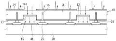
도 4는 도 1에 도시한 전사용 도너 기판과 전사 대상 기판을 나타낸 개략도이다. 도 4를 참고하면, 전사 대상 기판(20)(이하, '기판'이라 한다)은 복수의 화소 전극(41)과, 화소 영역을 구획하는 화소 정의막(25)을 포함한다. 전사용 도너 기판(10)은 광-열 변환층(12)이 특정 화소의 화소 전극(41)과 마주하도록 기판(20) 위에 정렬되며, 광원(도시하지 않음)은 반사층(14)과 마주하도록 전사용 도너 기판(10)의 외측에 위치한다.4 is a schematic view showing the transfer donor substrate and transfer target substrate shown in Fig. Referring to FIG. 4, a transfer target substrate 20 (hereinafter, referred to as a "substrate") includes a plurality of
광원에서 방출된 빛 중 반사층(14)에 도달한 빛은 반사층(14)에서 반사되고, 개구부(141)에 도달한 빛은 지지층(11)을 투과하여 광-열 변환층(12)으로 제공된다. 광-열 변환층(12)은 빛을 흡수하여 이를 열 에너지로 변환시키며, 광-열 변환층(12)의 열에 의해 전사층(13)이 증발되면서 기판(20) 위로 전사된다.Light reaching the
통상의 전사용 도너 기판에서 광-열 변환층과 반사층은 지지층의 같은 면에서 서로 접하도록 형성된다. 주로 광-열 변환층과 반사층 가운데 어느 한 층이 패터닝되고, 다른 한 층이 지지층의 일면 전체에 형성된다. 반사층은 열 전도율이 높은 금속층이므로, 광-열 변환층에서 발생된 열은 반사층으로 쉽게 전달된다. 따라서 전사층 가운데 의도하지 않은 부분까지 함께 증발되어 전사 정밀도가 저하될 수 있다.In a typical transfer donor substrate, the photo-thermal conversion layer and the reflection layer are formed so as to be in contact with each other on the same side of the support layer. Mainly one of the light-to-heat conversion layer and the reflective layer is patterned, and the other layer is formed on one entire surface of the support layer. Since the reflective layer is a metal layer having a high thermal conductivity, the heat generated in the light-to-heat conversion layer is easily transferred to the reflective layer. Therefore, unintended portions of the transfer layer may be evaporated together, and the transfer precision may be lowered.
그러나 본 실시예의 전사용 도너 기판(10)에서 광-열 변환층(12)과 반사층(14)은 지지층(11)의 반대 면에 형성되므로 서로 접하지 않는다. 또한, 광-열 변환층(12)과 반사층(14)은 서로에 대해 반대 모양으로 패터닝된다. 따라서 광-열 변환층(12)의 열은 반사층(14)으로 전도되지 않으므로, 전사층(13) 가운데 광-열 변환층(12)과 접하는 부분만을 정밀하게 증발시킬 수 있다.However, in the
이때 지지층(11)으로 유리 또는 석영과 같은 내열성 재료를 사용하는 경우, 광-열 변환층(12)의 열이 주변으로 전도되는 것을 더욱 효과적으로 차단할 수 있다. 이와 같이 본 실시예의 전사용 도너 기판(10)은 전사 정밀도를 향상시키며, 고해상도 유기 발광층 패턴을 용이하게 형성할 수 있다.At this time, when a heat resistant material such as glass or quartz is used as the
또한, 전사용 도너 기판(10)은 지지층(11)의 일면에 오목 홈(15)을 형성하고, 광-열 변환층(12)을 오목 홈(15)에 배치하여 전사층(13)의 확산각을 제한할 수 있다. 오목 홈(15)은 광-열 변환층(12)과 같은 위치에서 광-열 변환층(12)과 같은 모양으로 형성되며, 수직한 측벽을 형성할 수 있다. 광-열 변환층(12) 및 그 위의 전사층(13)은 오목 홈(15)의 깊이만큼 지지층(11)의 일면으로부터 떨어져 위치한다.The
광-열 변환층(12)의 열에 의해 전사층(13)이 증발될 때 오목 홈(15)의 측벽에 의해 확산 범위가 제한된다. 따라서 전사층(13)을 전사시켜 유기 발광층을 형성할 때 유기 발광층은 이웃 화소를 침범하지 않으며, 해당 화소 내에 균일한 두께로 형성될 수 있다. 이러한 유기 발광층을 포함하는 유기 발광 표시 장치는 색순도와 색수명 및 발광 효율이 향상되고, 화소 내 발광 균일도를 높일 수 있다.The diffusion range is limited by the side wall of the
화소 정의막(25) 위에 스페이서(26)가 형성될 수 있다. 그리고 전사용 도너 기판(10)은 스페이서(26)와 마주하는 부분에 폭이 좁은 홈부(16)를 형성할 수 있다. 홈부(16)는 화소 영역들 사이의 경계에 대응하므로 이웃한 광-열 변환층들(12) 사이에 하나 또는 복수개의 홈부(16)가 위치한다.A
지지층(11)에 형성된 홈부(16)는 광-열 변환층(12)의 열이 주변으로 전도되는 것을 억제하는 기능을 한다. 즉 지지층(11)이 내열성 재료로 형성되는 경우에도 지지층(11)을 통해 광-열 변환층(12)의 열이 일정 부분 주변으로 전도되는데, 홈부(16)를 형성하면 지지층(11)을 통한 열 전도를 효과적으로 차단할 수 있다.The
도 5는 도 1에 도시한 전사용 도너 기판 중 광-열 변환층과 홈부를 나타낸 부분 평면도이다. 도 4와 도 5를 참고하면, 홈부(16)는 화소 영역들 사이의 경계에 대응하여 격자 모양으로 형성될 수 있다. 홈부(16)의 폭은 오목 홈(15)의 폭보다 작으며, 홈부(16)의 깊이는 오목 홈(15)의 깊이보다 클 수 있다. 홈부(16)의 모양은 도 5에 도시한 예로 한정되지 않는다.5 is a partial plan view showing the light-to-heat conversion layer and the groove portion of the transfer donor substrate shown in Fig. 4 and 5, the
도 6은 본 발명의 제2 실시예에 따른 전사용 도너 기판의 부분 단면도이고, 도 7과 도 8은 각각 도 6에 도시한 전사용 도너 기판 중 광-열 변환층과 전사층의 부분 평면도이다.FIG. 6 is a partial cross-sectional view of a transfer donor substrate according to a second embodiment of the present invention, and FIGS. 7 and 8 are partial plan views of a photo-thermal conversion layer and a transfer layer of the transfer donor substrate shown in FIG. 6 .
도 6 내지 도 8을 참고하면, 제2 실시예의 전사용 도너 기판(101)은 공통 전극 위에 보조 전극을 형성하기 위한 용도인 것을 제외하고 전술한 제1 실시예와 유사한 구성으로 이루어진다. 제1 실시예와 같은 부재에 대해서는 같은 도면 부호를 사용한다.6 to 8, the
유기 발광 표시 장치에서 공통 전극 위로 보조 전극이 형성될 수 있다. 보조 전극은 대면적 공통 전극의 전압 강하를 보상하여 화면의 휘도 균일도를 높이는 역할을 한다. 보조 전극은 공통 전극 위에서 스트라이프 또는 격자 모양으로 형성될 수 있다.An auxiliary electrode may be formed over the common electrode in the organic light emitting display. The auxiliary electrode compensates the voltage drop of the large-area common electrode, thereby enhancing the brightness uniformity of the screen. The auxiliary electrode may be formed in a stripe or lattice shape on the common electrode.
제2 실시예에서 전사층(13)은 금속으로 형성되며, 예를 들어 알루미늄, 은, 금, 몰리브덴, 크롬, 텅스텐, 및 구리 등을 포함할 수 있다. 오목 홈(15)과 광-열 변환층(12)은 지지층(11)의 일면에서 스트라이프 또는 격자 모양으로 형성되고, 반사층(14)은 지지층(11)의 반대측 일면에서 광-열 변환층(12)과 반대 모양으로 형성된다.In the second embodiment, the
도 7에서는 광-열 변환층(12)이 격자 모양으로 형성된 경우를 도시하였고, 도 8에서는 반사층(14)이 격자 모양의 광-열 변환층(12)과 반대 모양으로 형성된 경우를 도시하였다. 즉 도 8에서 반사층(14)은 격자 모양의 개구부(141)를 형성한다. 광-열 변환층(12)과 반사층(14)의 모양은 도시한 예로 한정되지 않는다.FIG. 7 shows a case where the light-to-
도 9는 본 발명의 제3 실시예에 따른 유기 발광 표시 장치의 제조 방법을 나타낸 공정 순서도이다.9 is a flowchart illustrating a method of manufacturing an OLED display according to a third embodiment of the present invention.
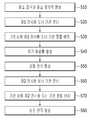
도 9를 참고하면, 유기 발광 표시 장치의 제조 방법은 기판 상에 화소 전극과 화소 정의막을 형성하는 제1 단계(S10)와, 지지층, 광-열 변환층, 전사층, 및 반사층을 포함하는 제1 전사용 도너 기판을 준비하는 제2 단계(S20)와, 광-열 변환층과 전사층이 화소 전극과 마주하도록 기판 상에 제1 전사용 도너 기판을 정렬 배치하는 제3 단계(S30)와, 제1 전사용 도너 기판으로 빛을 조사하고 광-열 변환층의 열에 의해 전사층을 화소 전극 위로 증발시켜 유기 발광층을 형성하는 제4 단계(S40)를 포함한다.Referring to FIG. 9, a method of manufacturing an organic light emitting display includes a first step (S10) of forming a pixel electrode and a pixel defining layer on a substrate, a step (S10) of forming a pixel electrode and a pixel defining layer A third step S30 of arranging the first transfer donor substrate on the substrate such that the photo-thermal conversion layer and the transfer layer face the pixel electrode, , And a fourth step (S40) of irradiating light onto the first transfer donor substrate and evaporating the transfer layer on the pixel electrode by heat of the photo-thermal conversion layer to form an organic light emitting layer.
도 10은 도 9에 도시한 제1 단계의 유기 발광 표시 장치를 나타낸 부분 확대 단면도이다.10 is a partially enlarged cross-sectional view of the organic light emitting display device of the first stage shown in FIG.
도 10을 참고하면, 기판(20)은 유리와 같은 강성(rigid) 기판이거나 고분자 필름과 같은 가요성(flexible) 기판일 수 있다. 기판(20) 위에 버퍼층(21)이 형성된다. 버퍼층(21)은 무기막으로 형성되며, 예를 들어 SiO2 또는 SiNx를 포함할 수 있다. 버퍼층(21)은 화소 회로를 형성하기 위한 평탄면을 제공하고, 화소 회로로 수분과 이물질이 침투하는 것을 억제한다.Referring to FIG. 10, the
버퍼층(21) 위에 박막 트랜지스터(30)와 커패시터(도시하지 않음)가 형성된다. 박막 트랜지스터(30)는 반도체층(31)과 게이트 전극(32) 및 소스/드레인 전극(33, 34)을 포함한다. 반도체층(31)은 폴리실리콘 또는 산화물 반도체로 형성될 수 있으며, 불순물이 도핑되지 않은 채널 영역과, 불순물이 도핑된 소스 영역 및 드레인 영역을 포함한다. 반도체층(31)이 산화물 반도체로 형성되는 경우 반도체층(31)을 보호하기 위한 별도의 보호층이 추가될 수 있다.A
반도체층(31)과 게이트 전극(32) 사이에 게이트 절연막(22)이 형성되고, 게이트 전극(32)과 소스/드레인 전극(33, 34) 사이에 층간 절연막(23)이 형성된다. 도 10에서는 탑 게이트 구조의 박막 트랜지스터(30)를 예로 들어 도시하였으나, 박막 트랜지스터(30)의 구조는 도시한 예로 한정되지 않는다. 커패시터는 게이트 절연막(22) 상에 형성된 제1 축전판과, 층간 절연막(23) 상에 형성된 제2 축전판을 포함할 수 있다.A
도 10에 도시한 박막 트랜지스터(30)는 구동 박막 트랜지스터이며, 화소 회로는 스위칭 박막 트랜지스터(도시하지 않음)를 더 포함한다. 스위칭 박막 트랜지스터는 발광시키고자 하는 화소를 선택하는 스위칭 소자로 형성되고, 구동 박막 트랜지스터는 선택된 화소를 발광시키기 위한 전원을 해당 화소로 인가한다. 화소는 최소의 발광 단위를 의미하며, 화소 회로는 적어도 두 개의 박막 트랜지스터와 적어도 하나의 커패시터를 포함한다.The
소스/드레인 전극(33, 34) 위로 평탄화층(24)이 형성된다. 평탄화층(24)은 벤조시클로부텐(benzocyclobutene, BCB), 아크릴 수지, 에폭시 수지, 및 페놀 수지와 같은 유기물, 또는 SiNx와 같은 무기물을 포함할 수 있다. 평탄화층(24)은 드레인 전극(34)의 일부를 노출시키는 비아 홀을 형성하며, 평탄화층(24) 위로 화소 전극(41)이 형성된다.A
화소 전극(41)은 화소마다 개별로 형성되고, 박막 트랜지스터(30)의 드레인 전극(34)과 연결된다. 화소 전극들(41)의 가장자리 위로 화소 영역을 구획하는 화소 정의막(25)이 형성된다. 화소 정의막(25)으로 덮이지 않고 노출된 화소 전극(41) 위로 다음에 설명하는 제2 단계 내지 제4 단계를 거쳐 유기 발광층이 형성된다. 화소 정의막(25) 위로 스페이서(26)가 형성될 수 있다.The
도 11는 도 9에 도시한 제2 단계와 제3 단계의 유기 발광 표시 장치를 나타낸 부분 확대 단면도이다.11 is a partially enlarged cross-sectional view of the organic light emitting display device of the second and third steps shown in FIG.
도 11을 참고하면, 제1 전사용 도너 기판(10)은 전술한 제1 실시예의 전사용 도너 기판이다. 전사층(13)은 유기 발광 물질을 포함하며, 광-열 변환층(12)은 형성하고자 하는 유기 발광층과 같은 모양으로 형성된다. 그리고 반사층(14)은 광-열 변환층(12)과 반대 모양으로 형성된다. 제1 전사용 도너 기판(10)의 구성은 전술한 제1 실시예의 내용과 동일하므로 중복되는 설명은 생략한다.Referring to Fig. 11, the first
제1 전사용 도너 기판(10)은 광-열 변환층(12)과 그 위의 전사층(13)이 전사 대상 화소의 화소 전극(41)과 마주하도록 기판(20) 위에 정렬된다. 광-열 변환층(12)은 오목 홈(15)에 형성되며, 지지층(11)은 스페이서(26)와 마주하는 부분에 홈부(16)를 형성할 수 있다.The first
도 12는 도 9에 도시한 제4 단계의 유기 발광 표시 장치를 나타낸 부분 확대 단면도이다.12 is a partially enlarged cross-sectional view of the organic light emitting display device of the fourth step shown in FIG.
도 12를 참고하면, 광원은 반사층(14)과 마주하도록 제1 전사용 도너 기판(10)의 외측에 위치하고, 제1 전사용 도너 기판(10)으로 빛을 조사한다. 그러면 광원에서 방출된 빛 가운데 반사층(14)에 도달한 빛은 반사층(14)에서 반사되며, 지지층(11)을 투과한 빛은 광-열 변환층(12)에서 열 에너지로 변환된다. 그리고 광-열 변환층(12)의 열에 의해 광-열 변환층(12) 상의 전사층(13)이 증발되면서 화소 전극(41) 위로 전사되어 유기 발광층(42)을 형성한다.Referring to FIG. 12, the light source is located outside the first
유기 발광층(42)은 적색 발광층과 녹색 발광층 및 청색 발광층 가운데 어느 하나일 수 있다. 다른 한편으로, 유기 발광층(42)은 백색 발광층이거나, 적색 발광층과 녹색 발광층 및 청색 발광층의 적층 구조로 형성될 수 있다. 유기 발광층(42)이 백색광을 방출하는 경우, 유기 발광 표시 장치는 색 필터(도시하지 않음)를 더 포함할 수 있다.The organic
제1 전사용 도너 기판(10)은 유기 발광층(42)의 색상 별로 따로 준비되고, 유기 발광층(42)의 색상 별로 전술한 제2 단계 내지 제4 단계가 반복된다.The first
유기 발광층(42)을 형성하는 과정에서 광-열 변환층(12)은 열 전도율이 높은 반사층(14)과 접하지 않으므로 열이 반사층(14)으로 전도됨에 따른 전사 정밀도 저하를 방지할 수 있다. 그리고 광-열 변환층(12)의 열은 지지층(11)을 통해서도 주변으로 전도되는데, 지지층(11)에 형성된 홈부(16)가 지지층(11)을 통한 열 전도를 차단한다. 이와 같이 광-열 변환층(12)의 열이 주변으로 전도되는 것을 최소화하여 유기 발광층(42)의 패턴 정밀도를 향상시킬 수 있다.In the process of forming the organic
그리고 광-열 변환층(12)과 그 위의 전사층(13)이 오목 홈(15)에 형성됨에 따라, 오목 홈(15)의 측벽에 의해 전사층(13)이 증발될 때 확산 범위가 제한된다. 이로써 유기 발광층(42)은 이웃 화소를 침범하지 않으며, 해당 화소 내에 균일한 두께로 형성될 수 있다. 따라서 유기 발광 표시 장치는 색순도와 색수명 및 발광 효율을 향상시킬 수 있고, 화소 내 발광 균일도를 높일 수 있다.When the
도 13은 본 발명의 제4 실시예에 따른 유기 발광 표시 장치의 제조 방법을 나타낸 공정 순서도이다.13 is a flowchart illustrating a method of manufacturing an OLED display according to a fourth embodiment of the present invention.
도 13을 참고하면, 유기 발광 표시 장치의 제조 방법은 전술한 제3 실시예의 제조 방법에서 유기 발광층 위로 공통 전극을 형성하는 제5 단계(S50)와, 지지층, 광-열 변환층, 전사층, 및 반사층을 포함하는 제2 전사용 도너 기판을 준비하는 제6 단계(S60)를 더 포함한다. 또한, 광-열 변환층과 전사층이 공통 전극과 마주하도록 기판 상에 제2 전사용 도너 기판을 정렬 배치하는 제7 단계(S70)와, 제2 전사용 도너 기판으로 빛을 조사하고 광-열 변환층의 열에 의해 전사층을 공통 전극 위로 증발시켜 보조 전극을 형성하는 제8 단계(S80)를 더 포함한다.Referring to FIG. 13, a method of manufacturing an organic light emitting display includes the fifth step (S50) of forming a common electrode on the organic light emitting layer in the manufacturing method of the third embodiment described above, And a sixth step (S60) of preparing a second transfer donor substrate including a reflection layer. (S70) aligning the second transfer donor substrate on the substrate such that the photo-thermal conversion layer and the transfer layer face the common electrode; and a third step of irradiating the second transfer donor substrate with the light- And an eighth step (S80) of forming an auxiliary electrode by evaporating the transfer layer onto the common electrode by the heat of the thermal conversion layer.
도 14는 도 13에 도시한 제5 단계의 유기 발광 표시 장치를 나타낸 부분 확대 단면도이다.14 is a partially enlarged cross-sectional view of the organic light emitting display device of the fifth step shown in FIG.
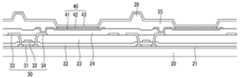
도 14를 참고하면, 유기 발광층(42)과 화소 정의막(25) 위로 표시 영역 전체에 공통 전극(43)이 형성된다. 화소 전극(41)과 유기 발광층(42) 및 공통 전극(43)이 유기 발광 다이오드(40)를 구성한다. 화소 전극(41)과 공통 전극(43) 중 어느 하나는 정공을 주입하는 애노드로 기능하고, 다른 하나는 전자를 주입하는 캐소드로 기능한다. 애노드로부터 주입된 정공과 캐소드로부터 주입된 전자가 유기 발광층(42)에서 결합하여 여기자(exciton)를 생성하며, 여기자가 에너지를 방출하면서 발광이 이루어진다.14, a
화소 전극(41)과 공통 전극(43) 중 어느 하나는 반사막으로 형성되고, 다른 하나는 반투과막 또는 투명 도전막으로 형성된다. 유기 발광층(42)에서 방출된 빛은 반사막에서 반사되고, 반투과막 또는 투명 도전막을 투과하여 외부로 방출된다. 반투과막의 경우 유기 발광층(42)에서 방출된 빛의 일부가 반사막으로 재반사되면서 공진 구조를 이룬다.Either the
도 15는 도 13에 도시한 제5 단계 내지 제7 단계의 유기 발광 표시 장치를 나타낸 부분 확대 단면도이다.15 is a partially enlarged cross-sectional view of the organic light emitting display device of the fifth to seventh steps shown in FIG.
도 15를 참고하면, 제2 전사용 도너 기판(101)은 전술한 제2 실시예의 전사용 도너 기판이다. 전사층(13)은 금속 물질을 포함한다. 광-열 변환층(12)은 보조 전극과 같은 패턴으로 형성되며, 반사층(14)은 광-열 변환층(12)에 대응하는 개구부(141)를 형성한다. 제2 전사용 도너 기판(101)의 구성은 전술한 제2 실시예의 내용과 동일하므로 중복되는 설명은 생략한다.Referring to Fig. 15, the second
제2 전사용 도너 기판(101)은 광-열 변환층(12)과 그 위의 전사층(13)이 공통 전극(43)과 마주하도록 기판(20) 위에 정렬된다.The second
도 16은 도 13에 도시한 제8 단계의 유기 발광 표시 장치를 나타낸 부분 확대 단면도이다.FIG. 16 is a partially enlarged cross-sectional view of the organic light emitting display device of the eighth step shown in FIG.
도 16을 참고하면, 광원은 반사층(14)과 마주하도록 제2 전사용 도너 기판(101)의 외측에 위치하고, 제2 전사용 도너 기판(101)으로 빛을 조사한다. 그러면 광원에서 방출된 빛 가운데 반사층(14)에 도달한 빛은 반사층(14)에서 반사되며, 지지층(11)을 투과한 빛은 광-열 변환층(12)에서 열 에너지로 변환된다. 그리고 광-열 변환층(12)의 열에 의해 광-열 변환층(12) 상의 전사층(13)이 증발되면서 공통 전극(43) 위로 전사되어 보조 전극(44)을 형성한다.16, the light source is located outside the second
보조 전극(44)은 대면적 공통 전극(43)의 전압 강하를 보상하여 화면의 휘도 균일도를 높이는 역할을 한다. 보조 전극(44)은 공통 전극(43) 위에서 스트라이프 또는 격자 모양으로 형성될 수 있다.The
보조 전극(44)을 형성하는 과정에서 광-열 변환층(12)은 열 전도율이 높은 반사층(14)과 접하지 않으므로 열이 반사층(14)으로 전도됨에 따른 전사 정밀도 저하를 방지할 수 있다. 그리고 광-열 변환층(12)과 그 위의 전사층(13)이 오목 홈(15)에 형성됨에 따라, 오목 홈(15)의 측벽에 의해 전사층(13)이 증발될 때 확산 범위가 제한된다. 따라서 보조 전극(44)의 패턴 정밀도를 향상시킬 수 있다.In the process of forming the
제8 단계(S80) 이후 공통 전극(43)은 봉지 기판 또는 박막 봉지층으로 덮인다. 봉지 기판 또는 박막 봉지층은 외기로부터 유기 발광 다이오드(40)를 밀봉시켜 외기에 포함된 수분과 산소에 의한 유기 발광 다이오드(40)의 열화를 억제한다.After the eighth step S80, the
유기 발광층(42)의 빛이 화소 전극(41)을 투과하여 외부로 방출되는 경우, 기판(20)의 외면(도 16을 기준으로 아랫면)에 터치 스크린 패널과 광학 필름들이 위치한다. 유기 발광층(42)의 빛이 공통 전극(43)을 투과하여 외부로 방출되는 경우, 봉지 기판 또는 박막 봉지층 위에 터치 스크린 패널과 광학 필름들이 위치한다.The touch screen panel and the optical films are positioned on the outer surface of the substrate 20 (the lower surface with reference to FIG. 16) when the light of the organic
상기에서는 본 발명의 바람직한 실시예에 대하여 설명하였지만, 본 발명은 이에 한정되는 것이 아니고 특허청구범위와 발명의 상세한 설명 및 첨부한 도면의 범위 안에서 여러 가지로 변형하여 실시하는 것이 가능하고 이 또한 본 발명의 범위에 속하는 것은 당연하다.While the present invention has been described in connection with what is presently considered to be practical exemplary embodiments, it is to be understood that the invention is not limited to the disclosed embodiments, but, on the contrary, Of course.
10, 101: 전사용 도너 기판11: 지지층
12: 광-열 변환층13: 전사층
14: 반사층15: 오목 홈
16: 홈부20: 기판
30: 박막 트랜지스터40: 유기 발광 다이오드
41: 화소 전극42: 유기 발광층
43: 공통 전극44: 보조 전극10, 101: Transfer donor substrate 11: Support layer
12: light-to-heat conversion layer 13: transfer layer
14: reflective layer 15: concave groove
16: groove 20: substrate
30: thin film transistor 40: organic light emitting diode
41: pixel electrode 42: organic light emitting layer
43: common electrode 44: auxiliary electrode
Claims (16)
Translated fromKorean상기 지지층의 일면에서 제1 패턴으로 형성되는 광-열 변환층;
상기 광-열 변환층을 덮는 전사층; 및
상기 지지층의 반대측 일면에서 제2 패턴으로 형성되는 반사층
을 포함하는 전사용 도너 기판.A transparent support layer;
A light-to-heat conversion layer formed in a first pattern on one side of the support layer;
A transfer layer covering the light-to-heat conversion layer; And
A reflective layer formed on the opposite side of the supporting layer in a second pattern,
Wherein the donor substrate is a substrate.
상기 제1 패턴은 전사하고자 하는 대상의 패턴과 동일하고,
상기 제2 패턴은 상기 제1 패턴과 동일한 개구부를 형성하는 전사용 도너 기판.The method according to claim 1,
The first pattern is the same as the pattern of the object to be transferred,
Wherein the second pattern forms the same opening as the first pattern.
상기 전사층은 유기 발광 물질을 포함하며,
상기 광-열 변환층은 전사하고자 하는 유기 발광층들과 같은 모양 및 같은 크기로 형성되는 전사용 도너 기판.3. The method of claim 2,
Wherein the transfer layer comprises an organic luminescent material,
Wherein the light-to-heat conversion layer is formed in the same shape and size as the organic light emitting layers to be transferred.
상기 지지층은 복수의 오목 홈을 형성하며,
상기 복수의 오목 홈 각각에 상기 광-열 변환층과 상기 전사층이 형성되는 전사용 도너 기판.The method of claim 3,
Wherein the support layer forms a plurality of concave grooves,
Wherein the light-to-heat conversion layer and the transfer layer are formed in each of the plurality of concave grooves.
상기 복수의 오목 홈 사이로 상기 오목 홈보다 큰 깊이를 가지는 홈부가 형성되는 전사용 도너 기판.5. The method of claim 4,
And a groove portion having a depth greater than that of the concave groove is formed between the plurality of concave grooves.
상기 전사층은 금속 물질을 포함하며,
상기 광-열 변환층은 전사하고자 하는 보조 전극과 같은 모양으로 형성되는 전사용 도너 기판.3. The method of claim 2,
Wherein the transfer layer comprises a metallic material,
Wherein the light-to-heat conversion layer is formed in the same shape as the auxiliary electrode to be transferred.
상기 지지층은 오목 홈을 형성하며,
상기 오목 홈에 상기 광-열 변환층과 상기 전사층이 형성되는 전사용 도너 기판.The method according to claim 6,
The supporting layer forms a concave groove,
Wherein the light-to-heat conversion layer and the transfer layer are formed on the concave groove.
상기 오목 홈과 상기 광-열 변환층은 스트라이프 또는 격자 모양으로 형성되는 전사용 도너 기판.8. The method of claim 7,
Wherein the concave groove and the photo-thermal conversion layer are formed in a stripe or lattice pattern.
상기 지지층은 유리, 석영, 및 고분자 물질 중 어느 하나를 포함하는 전사용 도너 기판.9. The method according to any one of claims 1 to 8,
Wherein the support layer comprises one of glass, quartz, and a polymeric material.
지지층, 지지층의 일면에서 유기 발광층과 같은 패턴으로 형성되는 광-열 변환층, 광-열 변환층을 덮는 전사층, 및 지지층의 반대측 일면에 형성되며 광-열 변환층에 대응하는 개구부를 형성하는 반사층을 포함하는 제1 전사용 도너 기판을 준비하는 단계;
상기 광-열 변환층과 상기 전사층이 상기 화소 전극과 마주하도록 상기 기판 상에 상기 제1 전사용 도너 기판을 정렬 배치하는 단계; 및
상기 제1 전사용 도너 기판으로 빛을 조사하고, 상기 광-열 변환층의 열에 의해 상기 전사층을 상기 화소 전극 위로 증발시켜 유기 발광층을 형성하는 단계
를 포함하는 유기 발광 표시 장치의 제조 방법.Forming a pixel electrode and a pixel defining layer on a substrate;
A support layer, a light-to-heat conversion layer formed on one surface of the support layer in the same pattern as the organic emission layer, a transfer layer covering the light-to-heat conversion layer, and an opening corresponding to the light- Preparing a first transfer donor substrate comprising a reflective layer;
Aligning the first transferred donor substrate on the substrate such that the photo-thermal conversion layer and the transfer layer face the pixel electrode; And
Irradiating light onto the first transfer donor substrate and evaporating the transfer layer on the pixel electrode by heat of the photo-thermal conversion layer to form an organic light emitting layer
Wherein the organic light emitting display device further comprises:
상기 지지층은 복수의 오목 홈을 형성하며,
상기 복수의 오목 홈 각각에 상기 광-열 변환층과 상기 전사층이 형성되는 유기 발광 표시 장치의 제조 방법.11. The method of claim 10,
Wherein the support layer forms a plurality of concave grooves,
And the light-to-heat conversion layer and the transfer layer are formed in each of the plurality of concave grooves.
상기 화소 정의막 위로 스페이서가 형성되며,
상기 지지층은 상기 스페이서와 마주하는 부위에 홈부를 형성하는 유기 발광 표시 장치의 제조 방법.12. The method of claim 11,
A spacer is formed on the pixel defining layer,
Wherein the support layer forms a groove portion at a portion facing the spacer.
상기 홈부의 폭은 상기 오목 홈의 폭보다 작고,
상기 홈부의 깊이는 상기 오목 홈의 깊이보다 큰 유기 발광 표시 장치의 제조 방법.13. The method of claim 12,
The width of the groove portion is smaller than the width of the concave groove,
Wherein a depth of the groove portion is larger than a depth of the concave groove.
상기 유기 발광층 위로 공통 전극을 형성하는 단계;
지지층, 지지층의 일면에서 보조 전극과 같은 패턴으로 형성되는 광-열 변환층, 광-열 변환층을 덮는 전사층, 및 지지층의 반대측 일면에 형성되며 광-열 변환층에 대응하는 개구부를 형성하는 반사층을 포함하는 제2 전사용 도너 필름을 준비하는 단계;
상기 광-열 변환층과 상기 전사층이 상기 공통 전극과 마주하도록 상기 기판 상에 제2 전사용 도너 기판을 정렬 배치하는 단계; 및
상기 제2 전사용 도너 기판으로 빛을 조사하고, 상기 광-열 변환층의 열에 의해 상기 전사층을 상기 공통 전극 위로 증발시켜 보조 전극을 형성하는 단계
를 더 포함하는 유기 발광 표시 장치의 제조 방법.14. The method according to any one of claims 10 to 13,
Forming a common electrode over the organic light emitting layer;
A support layer, a light-to-heat conversion layer formed on one surface of the support layer in the same pattern as the auxiliary electrode, a transfer layer covering the light-to-heat conversion layer, and an opening corresponding to the light- Preparing a second transfer donor film comprising a reflective layer;
Aligning the second transferred donor substrate on the substrate such that the light-to-heat conversion layer and the transfer layer face the common electrode; And
Irradiating light onto the second transfer donor substrate and evaporating the transfer layer on the common electrode by heat of the light-to-heat conversion layer to form an auxiliary electrode
Further comprising the steps of:
상기 지지층은 오목 홈을 형성하며,
상기 오목 홈에 상기 광-열 변환층과 상기 전사층이 형성되는 유기 발광 표시 장치의 제조 방법.15. The method of claim 14,
The supporting layer forms a concave groove,
And the light-to-heat conversion layer and the transfer layer are formed on the concave groove.
상기 오목 홈과 상기 광-열 변환층은 스트라이프 또는 격자 모양으로 형성되는 유기 발광 표시 장치의 제조 방법.16. The method of claim 15,
Wherein the concave groove and the light-to-heat conversion layer are formed in a stripe shape or a lattice shape.
Priority Applications (2)
| Application Number | Priority Date | Filing Date | Title |
|---|---|---|---|
| KR1020130076607AKR20150003570A (en) | 2013-07-01 | 2013-07-01 | Donor substrate for trnasfer and manufacturing method of organic light emitting diode display |
| US14/276,327US20150001495A1 (en) | 2013-07-01 | 2014-05-13 | Donor substrate for transfer and manufacturing method of organic light emitting diode display |
Applications Claiming Priority (1)
| Application Number | Priority Date | Filing Date | Title |
|---|---|---|---|
| KR1020130076607AKR20150003570A (en) | 2013-07-01 | 2013-07-01 | Donor substrate for trnasfer and manufacturing method of organic light emitting diode display |
Publications (1)
| Publication Number | Publication Date |
|---|---|
| KR20150003570Atrue KR20150003570A (en) | 2015-01-09 |
Family
ID=52114697
Family Applications (1)
| Application Number | Title | Priority Date | Filing Date |
|---|---|---|---|
| KR1020130076607AWithdrawnKR20150003570A (en) | 2013-07-01 | 2013-07-01 | Donor substrate for trnasfer and manufacturing method of organic light emitting diode display |
Country Status (2)
| Country | Link |
|---|---|
| US (1) | US20150001495A1 (en) |
| KR (1) | KR20150003570A (en) |
Cited By (2)
| Publication number | Priority date | Publication date | Assignee | Title |
|---|---|---|---|---|
| WO2019009587A1 (en)* | 2017-07-03 | 2019-01-10 | 한국생산기술연구원 | Donor substrate having light-to-heat conversion layer and hydrophobic thin-film pattern, donor substrate having light-to-heat conversion pattern and hydrophobic thin-film pattern, and method for forming light-emitting pattern by using donor substrate |
| KR20190004413A (en)* | 2017-07-03 | 2019-01-14 | 한국생산기술연구원 | Donor substrate having groove patterns, method of forming light emitting patterns by heating the same, light emitting pattern, and light emitting diode |
Families Citing this family (9)
| Publication number | Priority date | Publication date | Assignee | Title |
|---|---|---|---|---|
| KR20160003363A (en)* | 2014-06-30 | 2016-01-11 | 삼성디스플레이 주식회사 | Donor mask and method for manufacturing organic light-emitting display apparatus |
| KR102180647B1 (en)* | 2014-09-03 | 2020-11-23 | 삼성디스플레이 주식회사 | Optical mask |
| CN104882569B (en)* | 2015-06-24 | 2017-01-25 | 京东方科技集团股份有限公司 | OLED display device and its manufacturing method, display panel and display device |
| US10538260B2 (en)* | 2016-09-02 | 2020-01-21 | Exit Gear, LLC | System for converting a door to a cart |
| KR102300028B1 (en)* | 2017-06-08 | 2021-09-09 | 삼성디스플레이 주식회사 | Manufacturing method of organic light emitting display device |
| KR102474205B1 (en)* | 2017-12-26 | 2022-12-06 | 삼성디스플레이 주식회사 | Display apparatus and manufacturing the same |
| KR102618040B1 (en)* | 2018-08-09 | 2023-12-27 | 삼성디스플레이 주식회사 | Method for manufacturing display apparatus and display apparatus manufactured thereby |
| KR102671037B1 (en)* | 2018-11-07 | 2024-06-03 | 삼성디스플레이 주식회사 | Organic light emitting display apparatus and method of manufacturing the same |
| CN110164322A (en) | 2019-05-22 | 2019-08-23 | 深圳市华星光电半导体显示技术有限公司 | A kind of display panel and electronic device |
Family Cites Families (3)
| Publication number | Priority date | Publication date | Assignee | Title |
|---|---|---|---|---|
| KR20090028413A (en)* | 2007-09-13 | 2009-03-18 | 가부시키가이샤 한도오따이 에네루기 켄큐쇼 | Method of manufacturing light emitting device and substrate for deposition |
| JP5258666B2 (en)* | 2009-04-22 | 2013-08-07 | 株式会社半導体エネルギー研究所 | Method for manufacturing light emitting device and substrate for film formation |
| KR20130007092A (en)* | 2011-06-29 | 2013-01-18 | 삼성디스플레이 주식회사 | Donor substrate, method of manufacturing a donor substrate and method of manufacturing an organic light emitting display device using a donor substrate |
- 2013
- 2013-07-01KRKR1020130076607Apatent/KR20150003570A/ennot_activeWithdrawn
- 2014
- 2014-05-13USUS14/276,327patent/US20150001495A1/ennot_activeAbandoned
Cited By (3)
| Publication number | Priority date | Publication date | Assignee | Title |
|---|---|---|---|---|
| WO2019009587A1 (en)* | 2017-07-03 | 2019-01-10 | 한국생산기술연구원 | Donor substrate having light-to-heat conversion layer and hydrophobic thin-film pattern, donor substrate having light-to-heat conversion pattern and hydrophobic thin-film pattern, and method for forming light-emitting pattern by using donor substrate |
| KR20190004413A (en)* | 2017-07-03 | 2019-01-14 | 한국생산기술연구원 | Donor substrate having groove patterns, method of forming light emitting patterns by heating the same, light emitting pattern, and light emitting diode |
| KR20190004412A (en)* | 2017-07-03 | 2019-01-14 | 한국생산기술연구원 | Donor substrate having a light to heat conversion layer and hydrophobic thin film patterns, donor substrate having light to heat conversion patterns and hydrophobic thin film patterns, method of forming light emitting patterns by using a donor substrate, light emitting pattern, and light emitting diode |
Also Published As
| Publication number | Publication date |
|---|---|
| US20150001495A1 (en) | 2015-01-01 |
Similar Documents
| Publication | Publication Date | Title |
|---|---|---|
| KR20150003570A (en) | Donor substrate for trnasfer and manufacturing method of organic light emitting diode display | |
| US9287531B2 (en) | Organic light-emitting display device and method of manufacturing the same | |
| TWI666765B (en) | Electroluminescent display device | |
| KR101990116B1 (en) | Organic light emitting device and manufacture method thereof | |
| CN104576957B (en) | Organic electro-luminescence display device and its manufacture method | |
| TWI617020B (en) | Organic light emitting diode display | |
| EP3242344B1 (en) | Organic light-emitting diode array substrate, manufacturing method therefor, and display device | |
| CN109728065B (en) | Display substrate, preparation method thereof and display device | |
| KR102802881B1 (en) | Electroluminescent Display Device | |
| CN104716164A (en) | Array substrate and manufacturing method thereof and organic light-emitting display device | |
| KR20140123787A (en) | Organic luminescence display and method for manufacturing the same | |
| CN104282717A (en) | Organic light emitting display device and method of manufacturing same | |
| CN111613654A (en) | Display panel and display panel manufacturing method | |
| JP2006140145A (en) | Organic electroluminescence display | |
| CN1509127A (en) | Organic EL display device | |
| WO2019127801A1 (en) | Display panel and manufacturing method therefor | |
| US20140319475A1 (en) | Organic light emitting diode display and manufacturing method thereof | |
| CN107425043A (en) | Organic light emitting display and control method, display device | |
| KR20110047654A (en) | Manufacturing method of organic light emitting device | |
| KR20110035049A (en) | Organic electroluminescent device and manufacturing method thereof | |
| US20190198599A1 (en) | Electroluminescent display device | |
| US20150357392A1 (en) | Organic light-emitting diode (oled) display | |
| CN100388422C (en) | Donor substrate and method for manufacturing organic light emitting display | |
| KR20160030002A (en) | Donor mask and method for manufacturing organic light-emitting display apparatus using the same | |
| KR20080084618A (en) | Display |
Legal Events
| Date | Code | Title | Description |
|---|---|---|---|
| PA0109 | Patent application | Patent event code:PA01091R01D Comment text:Patent Application Patent event date:20130701 | |
| PG1501 | Laying open of application | ||
| PC1203 | Withdrawal of no request for examination | ||
| WITN | Application deemed withdrawn, e.g. because no request for examination was filed or no examination fee was paid |