KR20150003309A - Control circuit of a surgical device with a switch and a method for determining the state of the switch - Google Patents
Control circuit of a surgical device with a switch and a method for determining the state of the switchDownload PDFInfo
- Publication number
- KR20150003309A KR20150003309AKR1020147031616AKR20147031616AKR20150003309AKR 20150003309 AKR20150003309 AKR 20150003309AKR 1020147031616 AKR1020147031616 AKR 1020147031616AKR 20147031616 AKR20147031616 AKR 20147031616AKR 20150003309 AKR20150003309 AKR 20150003309A
- Authority
- KR
- South Korea
- Prior art keywords
- generator
- switch
- control circuit
- circuit
- impedance
- Prior art date
- Legal status (The legal status is an assumption and is not a legal conclusion. Google has not performed a legal analysis and makes no representation as to the accuracy of the status listed.)
- Granted
Links
- 238000000034methodMethods0.000titleclaimsdescription102
- 239000004020conductorSubstances0.000claimsabstractdescription36
- 239000003990capacitorSubstances0.000claimsdescription132
- 238000004891communicationMethods0.000claimsdescription59
- 230000007704transitionEffects0.000claimsdescription35
- 210000001519tissueAnatomy0.000description276
- 238000004422calculation algorithmMethods0.000description95
- 238000004804windingMethods0.000description91
- 238000002604ultrasonographyMethods0.000description79
- 239000002131composite materialSubstances0.000description69
- 230000006870functionEffects0.000description56
- 239000000523sampleSubstances0.000description54
- 238000002955isolationMethods0.000description46
- 230000000875corresponding effectEffects0.000description45
- 230000008569processEffects0.000description45
- 230000008859changeEffects0.000description35
- 238000013500data storageMethods0.000description35
- 230000003750conditioning effectEffects0.000description31
- XEEYBQQBJWHFJM-UHFFFAOYSA-NIronChemical compound[Fe]XEEYBQQBJWHFJM-UHFFFAOYSA-N0.000description30
- 239000012636effectorSubstances0.000description30
- 238000013528artificial neural networkMethods0.000description29
- 238000005259measurementMethods0.000description29
- 238000001356surgical procedureMethods0.000description27
- 238000001514detection methodMethods0.000description26
- 230000008030eliminationEffects0.000description25
- 238000003379elimination reactionMethods0.000description25
- 238000010586diagramMethods0.000description24
- 230000004913activationEffects0.000description21
- 238000005520cutting processMethods0.000description21
- 230000001276controlling effectEffects0.000description19
- 230000033001locomotionEffects0.000description18
- 230000003068static effectEffects0.000description18
- 230000000694effectsEffects0.000description15
- 229910052742ironInorganic materials0.000description15
- 230000001965increasing effectEffects0.000description14
- 230000000670limiting effectEffects0.000description14
- 239000000463materialSubstances0.000description14
- 238000005345coagulationMethods0.000description11
- 230000015271coagulationEffects0.000description11
- 230000002829reductive effectEffects0.000description11
- 238000003860storageMethods0.000description11
- 238000012546transferMethods0.000description11
- 230000002441reversible effectEffects0.000description10
- 230000000712assemblyEffects0.000description9
- 238000000429assemblyMethods0.000description9
- 230000000903blocking effectEffects0.000description9
- 238000013461designMethods0.000description9
- 238000012544monitoring processMethods0.000description9
- 238000003466weldingMethods0.000description9
- 238000010438heat treatmentMethods0.000description8
- 230000000737periodic effectEffects0.000description8
- 238000012545processingMethods0.000description8
- 230000000630rising effectEffects0.000description8
- 238000005070samplingMethods0.000description8
- 238000007711solidificationMethods0.000description8
- 230000008023solidificationEffects0.000description8
- 238000012549trainingMethods0.000description8
- 238000004364calculation methodMethods0.000description7
- 230000001052transient effectEffects0.000description7
- 238000002405diagnostic procedureMethods0.000description6
- 230000001976improved effectEffects0.000description6
- 230000003071parasitic effectEffects0.000description6
- 230000008901benefitEffects0.000description5
- 230000007246mechanismEffects0.000description5
- 238000012986modificationMethods0.000description5
- 230000004048modificationEffects0.000description5
- 230000004044responseEffects0.000description5
- 230000002457bidirectional effectEffects0.000description4
- 230000001186cumulative effectEffects0.000description4
- 239000002245particleSubstances0.000description4
- 229920006395saturated elastomerPolymers0.000description4
- 238000007789sealingMethods0.000description4
- 230000001360synchronised effectEffects0.000description4
- 230000000007visual effectEffects0.000description4
- 206010053567CoagulopathiesDiseases0.000description3
- 206010052428WoundDiseases0.000description3
- 208000027418Wounds and injuryDiseases0.000description3
- 230000009471actionEffects0.000description3
- 230000005540biological transmissionEffects0.000description3
- 230000015556catabolic processEffects0.000description3
- 238000006243chemical reactionMethods0.000description3
- 230000035602clottingEffects0.000description3
- 230000001112coagulating effectEffects0.000description3
- 230000008878couplingEffects0.000description3
- 238000010168coupling processMethods0.000description3
- 238000005859coupling reactionMethods0.000description3
- 230000000994depressogenic effectEffects0.000description3
- 238000001962electrophoresisMethods0.000description3
- 238000001914filtrationMethods0.000description3
- 238000002847impedance measurementMethods0.000description3
- 230000002452interceptive effectEffects0.000description3
- 238000003825pressingMethods0.000description3
- 238000010079rubber tappingMethods0.000description3
- 230000001953sensory effectEffects0.000description3
- 238000000926separation methodMethods0.000description3
- 101100458289Drosophila melanogaster msps geneProteins0.000description2
- 230000004075alterationEffects0.000description2
- 210000004204blood vesselAnatomy0.000description2
- 238000011109contaminationMethods0.000description2
- 239000002612dispersion mediumSubstances0.000description2
- 238000010292electrical insulationMethods0.000description2
- 238000005401electroluminescenceMethods0.000description2
- 230000005672electromagnetic fieldEffects0.000description2
- 230000005670electromagnetic radiationEffects0.000description2
- 239000010419fine particleSubstances0.000description2
- 230000036039immunityEffects0.000description2
- 230000000116mitigating effectEffects0.000description2
- 230000008520organizationEffects0.000description2
- 230000002093peripheral effectEffects0.000description2
- 230000009467reductionEffects0.000description2
- 238000002310reflectometryMethods0.000description2
- 238000010008shearingMethods0.000description2
- 230000011664signalingEffects0.000description2
- 239000000758substrateSubstances0.000description2
- 238000002560therapeutic procedureMethods0.000description2
- 238000012795verificationMethods0.000description2
- 238000012935AveragingMethods0.000description1
- 102000008186CollagenHuman genes0.000description1
- 108010035532CollagenProteins0.000description1
- 239000004593EpoxySubstances0.000description1
- CWYNVVGOOAEACU-UHFFFAOYSA-NFe2+Chemical compound[Fe+2]CWYNVVGOOAEACU-UHFFFAOYSA-N0.000description1
- BQCADISMDOOEFD-UHFFFAOYSA-NSilverChemical compound[Ag]BQCADISMDOOEFD-UHFFFAOYSA-N0.000description1
- 229910000831SteelInorganic materials0.000description1
- 239000004809TeflonSubstances0.000description1
- 229920006362Teflon®Polymers0.000description1
- 238000009825accumulationMethods0.000description1
- 230000003213activating effectEffects0.000description1
- 239000000853adhesiveSubstances0.000description1
- 230000001070adhesive effectEffects0.000description1
- 230000002411adverseEffects0.000description1
- 230000016571aggressive behaviorEffects0.000description1
- 238000013019agitationMethods0.000description1
- 230000003321amplificationEffects0.000description1
- 238000002266amputationMethods0.000description1
- 238000004458analytical methodMethods0.000description1
- 229940030225antihemorrhagicsDrugs0.000description1
- 238000013459approachMethods0.000description1
- 238000005452bendingMethods0.000description1
- 238000013529biological neural networkMethods0.000description1
- 230000033228biological regulationEffects0.000description1
- 230000015572biosynthetic processEffects0.000description1
- 210000004556brainAnatomy0.000description1
- 210000001715carotid arteryAnatomy0.000description1
- 239000003985ceramic capacitorSubstances0.000description1
- 238000012512characterization methodMethods0.000description1
- 238000003776cleavage reactionMethods0.000description1
- 229920001436collagenPolymers0.000description1
- 238000005094computer simulationMethods0.000description1
- 210000002808connective tissueAnatomy0.000description1
- 238000010276constructionMethods0.000description1
- 230000008094contradictory effectEffects0.000description1
- 230000002079cooperative effectEffects0.000description1
- 230000002596correlated effectEffects0.000description1
- 238000005260corrosionMethods0.000description1
- 230000007797corrosionEffects0.000description1
- 125000004122cyclic groupChemical group0.000description1
- 230000001419dependent effectEffects0.000description1
- 238000002224dissectionMethods0.000description1
- 238000001035dryingMethods0.000description1
- 230000009977dual effectEffects0.000description1
- 230000005684electric fieldEffects0.000description1
- 238000012976endoscopic surgical procedureMethods0.000description1
- 230000002349favourable effectEffects0.000description1
- 239000012530fluidSubstances0.000description1
- 239000002783friction materialSubstances0.000description1
- 230000014509gene expressionEffects0.000description1
- 230000000025haemostatic effectEffects0.000description1
- 231100001261hazardousToxicity0.000description1
- 230000023597hemostasisEffects0.000description1
- 230000002439hemostatic effectEffects0.000description1
- 230000013632homeostatic processEffects0.000description1
- 230000006872improvementEffects0.000description1
- 230000006698inductionEffects0.000description1
- 230000001939inductive effectEffects0.000description1
- 230000036512infertilityEffects0.000description1
- 230000000977initiatory effectEffects0.000description1
- 208000014674injuryDiseases0.000description1
- 238000012830laparoscopic surgical procedureMethods0.000description1
- 239000004973liquid crystal related substanceSubstances0.000description1
- 238000004519manufacturing processMethods0.000description1
- 238000013178mathematical modelMethods0.000description1
- 239000002609mediumSubstances0.000description1
- 238000003199nucleic acid amplification methodMethods0.000description1
- 230000010355oscillationEffects0.000description1
- 238000012856packingMethods0.000description1
- 230000000750progressive effectEffects0.000description1
- 230000001737promoting effectEffects0.000description1
- 230000001902propagating effectEffects0.000description1
- 108090000623proteins and genesProteins0.000description1
- 102000004169proteins and genesHuman genes0.000description1
- 230000005855radiationEffects0.000description1
- 238000013349risk mitigationMethods0.000description1
- 230000007017scissionEffects0.000description1
- 229910052709silverInorganic materials0.000description1
- 239000004332silverSubstances0.000description1
- 210000004872soft tissueAnatomy0.000description1
- 238000001228spectrumMethods0.000description1
- 239000010959steelSubstances0.000description1
- 238000003786synthesis reactionMethods0.000description1
- BFKJFAAPBSQJPD-UHFFFAOYSA-NtetrafluoroetheneChemical compoundFC(F)=C(F)FBFKJFAAPBSQJPD-UHFFFAOYSA-N0.000description1
- 230000001225therapeutic effectEffects0.000description1
- 230000000451tissue damageEffects0.000description1
- 231100000827tissue damageToxicity0.000description1
- 230000008733traumaEffects0.000description1
- 238000005406washingMethods0.000description1
Images


Classifications
- A—HUMAN NECESSITIES
- A61—MEDICAL OR VETERINARY SCIENCE; HYGIENE
- A61B—DIAGNOSIS; SURGERY; IDENTIFICATION
- A61B18/00—Surgical instruments, devices or methods for transferring non-mechanical forms of energy to or from the body
- A61B18/04—Surgical instruments, devices or methods for transferring non-mechanical forms of energy to or from the body by heating
- A61B18/12—Surgical instruments, devices or methods for transferring non-mechanical forms of energy to or from the body by heating by passing a current through the tissue to be heated, e.g. high-frequency current
- A61B18/1206—Generators therefor
- A—HUMAN NECESSITIES
- A61—MEDICAL OR VETERINARY SCIENCE; HYGIENE
- A61N—ELECTROTHERAPY; MAGNETOTHERAPY; RADIATION THERAPY; ULTRASOUND THERAPY
- A61N7/00—Ultrasound therapy
- H—ELECTRICITY
- H01—ELECTRIC ELEMENTS
- H01H—ELECTRIC SWITCHES; RELAYS; SELECTORS; EMERGENCY PROTECTIVE DEVICES
- H01H1/00—Contacts
- H—ELECTRICITY
- H03—ELECTRONIC CIRCUITRY
- H03M—CODING; DECODING; CODE CONVERSION IN GENERAL
- H03M11/00—Coding in connection with keyboards or like devices, i.e. coding of the position of operated keys
- H03M11/22—Static coding
- H03M11/24—Static coding using analogue means, e.g. by coding the states of multiple switches into a single multi-level analogue signal or by indicating the type of a device using the voltage level at a specific tap of a resistive divider
- A—HUMAN NECESSITIES
- A61—MEDICAL OR VETERINARY SCIENCE; HYGIENE
- A61B—DIAGNOSIS; SURGERY; IDENTIFICATION
- A61B18/00—Surgical instruments, devices or methods for transferring non-mechanical forms of energy to or from the body
- A61B18/04—Surgical instruments, devices or methods for transferring non-mechanical forms of energy to or from the body by heating
- A61B18/12—Surgical instruments, devices or methods for transferring non-mechanical forms of energy to or from the body by heating by passing a current through the tissue to be heated, e.g. high-frequency current
- A61B18/1206—Generators therefor
- A61B18/1233—Generators therefor with circuits for assuring patient safety
- A—HUMAN NECESSITIES
- A61—MEDICAL OR VETERINARY SCIENCE; HYGIENE
- A61B—DIAGNOSIS; SURGERY; IDENTIFICATION
- A61B18/00—Surgical instruments, devices or methods for transferring non-mechanical forms of energy to or from the body
- A61B18/04—Surgical instruments, devices or methods for transferring non-mechanical forms of energy to or from the body by heating
- A61B18/12—Surgical instruments, devices or methods for transferring non-mechanical forms of energy to or from the body by heating by passing a current through the tissue to be heated, e.g. high-frequency current
- A61B18/14—Probes or electrodes therefor
- A61B18/1442—Probes having pivoting end effectors, e.g. forceps
- A61B18/1445—Probes having pivoting end effectors, e.g. forceps at the distal end of a shaft, e.g. forceps or scissors at the end of a rigid rod
- A—HUMAN NECESSITIES
- A61—MEDICAL OR VETERINARY SCIENCE; HYGIENE
- A61B—DIAGNOSIS; SURGERY; IDENTIFICATION
- A61B17/00—Surgical instruments, devices or methods
- A61B2017/00017—Electrical control of surgical instruments
- A61B2017/00137—Details of operation mode
- A61B2017/00154—Details of operation mode pulsed
- A—HUMAN NECESSITIES
- A61—MEDICAL OR VETERINARY SCIENCE; HYGIENE
- A61B—DIAGNOSIS; SURGERY; IDENTIFICATION
- A61B17/00—Surgical instruments, devices or methods
- A61B2017/00477—Coupling
- A—HUMAN NECESSITIES
- A61—MEDICAL OR VETERINARY SCIENCE; HYGIENE
- A61B—DIAGNOSIS; SURGERY; IDENTIFICATION
- A61B17/00—Surgical instruments, devices or methods
- A61B2017/00477—Coupling
- A61B2017/00486—Adaptors for coupling parts with incompatible geometries
- A—HUMAN NECESSITIES
- A61—MEDICAL OR VETERINARY SCIENCE; HYGIENE
- A61B—DIAGNOSIS; SURGERY; IDENTIFICATION
- A61B17/00—Surgical instruments, devices or methods
- A61B2017/00973—Surgical instruments, devices or methods pedal-operated
- A—HUMAN NECESSITIES
- A61—MEDICAL OR VETERINARY SCIENCE; HYGIENE
- A61B—DIAGNOSIS; SURGERY; IDENTIFICATION
- A61B17/00—Surgical instruments, devices or methods
- A61B17/28—Surgical forceps
- A61B17/29—Forceps for use in minimally invasive surgery
- A61B2017/2926—Details of heads or jaws
- A61B2017/2932—Transmission of forces to jaw members
- A61B2017/2933—Transmission of forces to jaw members camming or guiding means
- A61B2017/2934—Transmission of forces to jaw members camming or guiding means arcuate shaped guiding means
- A—HUMAN NECESSITIES
- A61—MEDICAL OR VETERINARY SCIENCE; HYGIENE
- A61B—DIAGNOSIS; SURGERY; IDENTIFICATION
- A61B17/00—Surgical instruments, devices or methods
- A61B17/28—Surgical forceps
- A61B17/29—Forceps for use in minimally invasive surgery
- A61B2017/2926—Details of heads or jaws
- A61B2017/2932—Transmission of forces to jaw members
- A61B2017/2933—Transmission of forces to jaw members camming or guiding means
- A61B2017/2936—Pins in guiding slots
- A—HUMAN NECESSITIES
- A61—MEDICAL OR VETERINARY SCIENCE; HYGIENE
- A61B—DIAGNOSIS; SURGERY; IDENTIFICATION
- A61B17/00—Surgical instruments, devices or methods
- A61B17/32—Surgical cutting instruments
- A61B17/320068—Surgical cutting instruments using mechanical vibrations, e.g. ultrasonic
- A61B2017/320069—Surgical cutting instruments using mechanical vibrations, e.g. ultrasonic for ablating tissue
- A—HUMAN NECESSITIES
- A61—MEDICAL OR VETERINARY SCIENCE; HYGIENE
- A61B—DIAGNOSIS; SURGERY; IDENTIFICATION
- A61B17/00—Surgical instruments, devices or methods
- A61B17/32—Surgical cutting instruments
- A61B17/320068—Surgical cutting instruments using mechanical vibrations, e.g. ultrasonic
- A61B17/320092—Surgical cutting instruments using mechanical vibrations, e.g. ultrasonic with additional movable means for clamping or cutting tissue, e.g. with a pivoting jaw
- A61B2017/320093—Surgical cutting instruments using mechanical vibrations, e.g. ultrasonic with additional movable means for clamping or cutting tissue, e.g. with a pivoting jaw additional movable means performing cutting operation
- A—HUMAN NECESSITIES
- A61—MEDICAL OR VETERINARY SCIENCE; HYGIENE
- A61B—DIAGNOSIS; SURGERY; IDENTIFICATION
- A61B17/00—Surgical instruments, devices or methods
- A61B17/32—Surgical cutting instruments
- A61B17/320068—Surgical cutting instruments using mechanical vibrations, e.g. ultrasonic
- A61B17/320092—Surgical cutting instruments using mechanical vibrations, e.g. ultrasonic with additional movable means for clamping or cutting tissue, e.g. with a pivoting jaw
- A61B2017/320094—Surgical cutting instruments using mechanical vibrations, e.g. ultrasonic with additional movable means for clamping or cutting tissue, e.g. with a pivoting jaw additional movable means performing clamping operation
- A—HUMAN NECESSITIES
- A61—MEDICAL OR VETERINARY SCIENCE; HYGIENE
- A61B—DIAGNOSIS; SURGERY; IDENTIFICATION
- A61B17/00—Surgical instruments, devices or methods
- A61B17/32—Surgical cutting instruments
- A61B17/320068—Surgical cutting instruments using mechanical vibrations, e.g. ultrasonic
- A61B17/320092—Surgical cutting instruments using mechanical vibrations, e.g. ultrasonic with additional movable means for clamping or cutting tissue, e.g. with a pivoting jaw
- A61B2017/320095—Surgical cutting instruments using mechanical vibrations, e.g. ultrasonic with additional movable means for clamping or cutting tissue, e.g. with a pivoting jaw with sealing or cauterizing means
- A—HUMAN NECESSITIES
- A61—MEDICAL OR VETERINARY SCIENCE; HYGIENE
- A61B—DIAGNOSIS; SURGERY; IDENTIFICATION
- A61B18/00—Surgical instruments, devices or methods for transferring non-mechanical forms of energy to or from the body
- A61B2018/00053—Mechanical features of the instrument of device
- A61B2018/00172—Connectors and adapters therefor
- A61B2018/00178—Electrical connectors
- A—HUMAN NECESSITIES
- A61—MEDICAL OR VETERINARY SCIENCE; HYGIENE
- A61B—DIAGNOSIS; SURGERY; IDENTIFICATION
- A61B18/00—Surgical instruments, devices or methods for transferring non-mechanical forms of energy to or from the body
- A61B2018/00636—Sensing and controlling the application of energy
- A61B2018/00666—Sensing and controlling the application of energy using a threshold value
- A61B2018/00678—Sensing and controlling the application of energy using a threshold value upper
- A—HUMAN NECESSITIES
- A61—MEDICAL OR VETERINARY SCIENCE; HYGIENE
- A61B—DIAGNOSIS; SURGERY; IDENTIFICATION
- A61B18/00—Surgical instruments, devices or methods for transferring non-mechanical forms of energy to or from the body
- A61B2018/00636—Sensing and controlling the application of energy
- A61B2018/00696—Controlled or regulated parameters
- A61B2018/00714—Temperature
- A—HUMAN NECESSITIES
- A61—MEDICAL OR VETERINARY SCIENCE; HYGIENE
- A61B—DIAGNOSIS; SURGERY; IDENTIFICATION
- A61B18/00—Surgical instruments, devices or methods for transferring non-mechanical forms of energy to or from the body
- A61B2018/00636—Sensing and controlling the application of energy
- A61B2018/00773—Sensed parameters
- A61B2018/00779—Power or energy
- A—HUMAN NECESSITIES
- A61—MEDICAL OR VETERINARY SCIENCE; HYGIENE
- A61B—DIAGNOSIS; SURGERY; IDENTIFICATION
- A61B18/00—Surgical instruments, devices or methods for transferring non-mechanical forms of energy to or from the body
- A61B2018/00636—Sensing and controlling the application of energy
- A61B2018/00773—Sensed parameters
- A61B2018/00791—Temperature
- A—HUMAN NECESSITIES
- A61—MEDICAL OR VETERINARY SCIENCE; HYGIENE
- A61B—DIAGNOSIS; SURGERY; IDENTIFICATION
- A61B18/00—Surgical instruments, devices or methods for transferring non-mechanical forms of energy to or from the body
- A61B2018/00636—Sensing and controlling the application of energy
- A61B2018/00773—Sensed parameters
- A61B2018/00875—Resistance or impedance
- A—HUMAN NECESSITIES
- A61—MEDICAL OR VETERINARY SCIENCE; HYGIENE
- A61B—DIAGNOSIS; SURGERY; IDENTIFICATION
- A61B18/00—Surgical instruments, devices or methods for transferring non-mechanical forms of energy to or from the body
- A61B2018/00988—Means for storing information, e.g. calibration constants, or for preventing excessive use, e.g. usage, service life counter
- A—HUMAN NECESSITIES
- A61—MEDICAL OR VETERINARY SCIENCE; HYGIENE
- A61B—DIAGNOSIS; SURGERY; IDENTIFICATION
- A61B18/00—Surgical instruments, devices or methods for transferring non-mechanical forms of energy to or from the body
- A61B2018/00994—Surgical instruments, devices or methods for transferring non-mechanical forms of energy to or from the body combining two or more different kinds of non-mechanical energy or combining one or more non-mechanical energies with ultrasound
- A—HUMAN NECESSITIES
- A61—MEDICAL OR VETERINARY SCIENCE; HYGIENE
- A61B—DIAGNOSIS; SURGERY; IDENTIFICATION
- A61B18/00—Surgical instruments, devices or methods for transferring non-mechanical forms of energy to or from the body
- A61B18/04—Surgical instruments, devices or methods for transferring non-mechanical forms of energy to or from the body by heating
- A61B18/12—Surgical instruments, devices or methods for transferring non-mechanical forms of energy to or from the body by heating by passing a current through the tissue to be heated, e.g. high-frequency current
- A61B18/1206—Generators therefor
- A61B2018/1273—Generators therefor including multiple generators in one device
- H—ELECTRICITY
- H01—ELECTRIC ELEMENTS
- H01H—ELECTRIC SWITCHES; RELAYS; SELECTORS; EMERGENCY PROTECTIVE DEVICES
- H01H2239/00—Miscellaneous
- H01H2239/01—Miscellaneous combined with other elements on the same substrate
- H01H2239/012—Decoding impedances
Landscapes
- Health & Medical Sciences (AREA)
- Engineering & Computer Science (AREA)
- Life Sciences & Earth Sciences (AREA)
- Surgery (AREA)
- Animal Behavior & Ethology (AREA)
- Veterinary Medicine (AREA)
- Nuclear Medicine, Radiotherapy & Molecular Imaging (AREA)
- Public Health (AREA)
- Biomedical Technology (AREA)
- General Health & Medical Sciences (AREA)
- Heart & Thoracic Surgery (AREA)
- Medical Informatics (AREA)
- Molecular Biology (AREA)
- Physics & Mathematics (AREA)
- Otolaryngology (AREA)
- Plasma & Fusion (AREA)
- Theoretical Computer Science (AREA)
- Radiology & Medical Imaging (AREA)
- Surgical Instruments (AREA)
- Dentistry (AREA)
- Mechanical Engineering (AREA)
- Neurology (AREA)
Abstract
Translated fromKoreanDescription
Translated fromKorean관련 출원의 상호 참조Cross reference of related application
본 출원은 2011년 10월 3일자로 출원되고 발명의 명칭이 "초음파 및 전기수술용 장치를 위한 수술용 발생기(SURGICAL GENERATOR FOR ULTRASONIC AND ELECTROSURGICAL DEVICES)"인 공계류 중인 미국 특허 출원 제13/251,766호의 일부 계속 출원이며, 이 미국 특허 출원은 2010년 10월 1일자로 출원되고 발명의 명칭이 "초음파 및 전기수술용 장치를 위한 수술용 발생기"인 공계류 중인 미국 특허 출원 제12/896,360호의 일부 계속 출원이고, 2009년 10월 9일자로 출원되고 발명의 명칭이 "전기수술용 기구를 위한 이중 양극 및 초음파 발생기(A DUAL BIPOLAR AND ULTRASONIC GENERATOR FOR ELECTRO-SURGICAL INSTRUMENTS)"인 미국 가특허 출원 제61/250,217호의, 타이틀 35, USC(Title 35, United States Code) § 119(e) 하에서의 이익을 주장한다. 이들 출원 각각은 이로써 전체적으로 참고로 포함된다.This application is related to co-pending U.S. Patent Application No. 13 / 251,766, filed October 3, 2011, entitled " SURGICAL GENERATOR FOR ULTRASONIC AND ELECTROSURGICAL DEVICES FOR EQUIPMENT & This U.S. patent application is a continuation-in-part of U.S. Patent Application No. 12 / 896,360, filed October 1, 2010, entitled " Surgical Generator for Ultrasound & Filed October 9, 2009, entitled " DUAL BIPOLAR AND ULTRASONIC GENERATOR FOR ELECTRO-SURGICAL INSTRUMENTS FOR ELECTRO-SURGICAL APPARATUS, " 250,217,
본 출원은 또한 2011년 10월 3일자로 동시에 출원된 하기의 미국 특허 출원들에 관련되며, 이들 각각은 전체적으로 본 명세서에 참고로 포함된다:This application is also related to the following U.S. patent applications filed concurrently on October 3, 2011, each of which is incorporated herein by reference in its entirety:
(1) 발명의 명칭이 "조직을 절단 및 응고시키기 위한 장치 및 기술(DEVICES AND TECHNIQUES FOR CUTTING AND COAGULATING TISSUE)"인 미국 특허 출원 제12/896,351호, 대리인 문서 번호 END6427USCIP1/080591CIP;(1) U.S. Patent Application No. 12 / 896,351 entitled " DEVICES AND TECHNIQUES FOR CUTTING AND COAGULATING TISSUE ", Attorney Docket No. END6427USCIP1 / 080591CIP;
(2) 발명의 명칭이 "초음파 및 전기수술용 장치를 위한 수술용 발생기(SURGICAL GENERATOR FOR ULTRASONIC AND ELECTROSURGICAL DEVICES)"인 미국 특허 출원 제12/896,479호, 대리인 문서 번호 END6673USNP1/100557;(2) U.S. Patent Application No. 12 / 896,479 entitled "SURGICAL GENERATOR FOR ULTRASONIC AND ELECTROSURGICAL DEVICES FOR ULTRASOUND AND ELECTROSURGICAL DEVICES", Attorney Docket No. END6673USNP1 / 100557;
(3) 발명의 명칭이 "초음파 및 전기수술용 장치를 위한 수술용 발생기(SURGICAL GENERATOR FOR ULTRASONIC AND ELECTROSURGICAL DEVICES)"인 미국 특허 출원 제12/896,345호, 대리인 문서 번호 END6673USNP2/100559;(3) U.S. Patent Application No. 12 / 896,345, entitled "SURGICAL GENERATOR FOR ULTRASONIC AND ELECTROSURGICAL DEVICES FOR ULTRASOUND AND ELECTROSURGICAL DEVICES", Attorney Docket No. END6673USNP2 / 100559;
(4) 발명의 명칭이 "초음파 및 전기수술용 장치를 위한 수술용 발생기(SURGICAL GENERATOR FOR ULTRASONIC AND ELECTROSURGICAL DEVICES)"인 미국 특허 출원 제12/896,384호, 대리인 문서 번호 END6673USNP3/100560;(4) U.S. Patent Application No. 12 / 896,384 entitled "SURGICAL GENERATOR FOR ULTRASONIC AND ELECTROSURGICAL DEVICES FOR ULTRASOUND AND ELECTROSURGICAL DEVICES", Attorney Docket No. END6673USNP3 / 100560;
(5) 발명의 명칭이 "초음파 및 전기수술용 장치를 위한 수술용 발생기(SURGICAL GENERATOR FOR ULTRASONIC AND ELECTROSURGICAL DEVICES)"인 미국 특허 출원 제12/896,467호, 대리인 문서 번호 END6673USNP4/100562;(5) U.S. Patent Application No. 12 / 896,467 entitled "SURGICAL GENERATOR FOR ULTRASONIC AND ELECTROSURGICAL DEVICES FOR ULTRASOUND AND ELECTROSURGICAL DEVICES", Attorney Docket No. END6673USNP4 / 100562;
(6) 발명의 명칭이 "초음파 및 전기수술용 장치를 위한 수술용 발생기(SURGICAL GENERATOR FOR ULTRASONIC AND ELECTROSURGICAL DEVICES)"인 미국 특허 출원 제12/896,451호, 대리인 문서 번호 END6673USNP5/100563; 및(6) U.S. Patent Application No. 12 / 896,451 entitled "SURGICAL GENERATOR FOR ULTRASONIC AND ELECTROSURGICAL DEVICES FOR ULTRASOUND AND ELECTROSURGICAL DEVICES", Attorney Docket No. END6673USNP5 / 100563; And
(7) 발명의 명칭이 "초음파 및 전기수술용 장치를 위한 수술용 발생기(SURGICAL GENERATOR FOR ULTRASONIC AND ELECTROSURGICAL DEVICES)"인 미국 특허 출원 제12/896,470호, 대리인 문서 번호 END6673USNP6/100564.(7) U.S. Patent Application No. 12 / 896,470 entitled "SURGICAL GENERATOR FOR ULTRASONIC AND ELECTROSURGICAL DEVICES FOR ULTRASOUND AND ELECTROSURGICAL DEVICES", Attorney Docket No. END6673USNP6 / 100564.
다양한 실시예는 개복 또는 최소 침습적 수술 환경에서 사용하기 위한, 수술용 장치 및 수술용 장치에 에너지를 공급하기 위한 발생기(generator)에 관한 것이다.Various embodiments are directed to a surgical device and a generator for energizing the surgical device for use in an open or minimally invasive surgical environment.
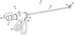
초음파 스캘펠(ultrasonic scalpel)과 같은 초음파 수술용 장치는 그들 고유의 성능 특성들로 인해 수술적 시술에서 점점 더 확대되는 응용들을 발견하고 있다. 특정 장치 구성들 및 동작 파라미터들에 따라, 초음파 수술용 장치는 실질적으로 동시에 조직의 절개 및 응고에 의한 항상성(homeostasis)을 제공할 수 있어서, 환자의 외상을 바람직하게 최소화한다. 초음파 수술용 장치는 초음파 트랜스듀서(ultrasonic transducer)를 포함하는 핸드피스(handpiece), 및 조직을 절단하고 봉합하도록 원위에 장착된 단부 작동기(end effector)(예컨대, 블레이드 팁(blade tip))를 갖는, 초음파 트랜스듀서에 커플링되는 기구를 포함할 수 있다. 일부 경우에, 기구는 핸드피스에 영구적으로 부착될 수 있다. 다른 경우에, 기구는 일회용 기구 또는 상이한 핸드피스들 간에 상호교환가능한 기구의 경우에서와 같이, 핸드피스로부터 탈착가능할 수 있다. 단부 작동기는 절단 및 봉합 작용을 실현하기 위해 단부 작동기와 접촉하게 되는 조직으로 초음파 에너지를 전달한다. 이러한 특성의 초음파 수술용 장치는 개복 수술용 용도, 복강경 또는 내시경 수술적 시술(로봇 보조식 시술을 포함함)을 위해 구성될 수 있다.Ultrasonic surgical devices such as ultrasonic scalpels have found applications that are increasingly widening in surgical procedures due to their inherent performance characteristics. Depending on the specific device configurations and operating parameters, the device for ultrasound surgery can substantially simultaneously provide homeostasis by tissue dissection and coagulation, thereby minimizing trauma to the patient. The device for ultrasound surgery includes a handpiece including an ultrasonic transducer and an end effector (e.g., a blade tip) mounted on a circle to cut and seal the tissue , And a mechanism coupled to the ultrasonic transducer. In some cases, the instrument may be permanently attached to the handpiece. In other cases, the instrument may be removable from the handpiece, such as in the case of disposable instruments or interchangeable instruments between different handpieces. The end effector transfers ultrasonic energy to the tissue that is in contact with the end effector to achieve the cutting and sealing action. Devices of this nature for ultrasound surgery can be configured for open surgical applications, laparoscopic or endoscopic surgical procedures (including robotic assisted procedures).
초음파 에너지는 전기수술적 시술에 사용되는 온도보다 낮은 온도를 사용하여 조직을 절단 및 응고시키며, 핸드피스와 통신하는 초음파 발생기에 의해 단부 작동기로 전달될 수 있다. 고 주파수(예컨대, 55,500 회/초)에서 진동함으로써, 초음파 블레이드는 점착성 응고물(sticky coagulum)을 형성하도록 조직 내의 단백질을 변성시킨다. 블레이드 표면에 의해 조직에 가해진 압력은 혈관을 허탈시키고(collpase), 응고물이 지혈 봉합부(haemostatic seal)를 형성하게 한다. 외과의는 단부 작동기에 의해 조직에 가해지는 힘, 힘이 가해지는 시간 및 단부 작동기의 선택된 진폭 레벨에 의해 절단 속도 및 응고를 제어할 수 있다.Ultrasonic energy can be delivered to the end effector by an ultrasonic generator communicating with the handpiece, cutting and coagulating tissue using temperatures lower than the temperatures used in electrosurgical procedures. By vibrating at high frequencies (e.g., 55,500 times / second), the ultrasonic blades denature proteins in the tissue to form sticky coagulum. The pressure applied to the tissue by the blade surface collapses the vessel and causes the clot to form a haemostatic seal. The surgeon can control the cutting speed and solidification by the force applied to the tissue by the end effector, the time the force is applied and the selected amplitude level of the end effector.
초음파 트랜스듀서는 정적 용량(static capacitance)을 갖는 제1 분로(branch) 및 공진기의 전기기계적 특성들을 정의하는 직렬로 접속된 인덕턴스(inductance), 저항 및 용량을 갖는 제2 "운동" 분로(motional branch)를 포함하는 등가 회로로서 모델링될 수 있다. 공지된 초음파 발생기는 발생기의 구동 신호 전류의 실질적으로 전부가 운동 분로 내로 흐르도록 공진 주파수에서 정적 용량을 튜닝 아웃(tuning out)하기 위한 튜닝 인덕터(tuning inductor)를 포함할 수 있다. 따라서, 튜닝 인덕터를 사용함으로써, 발생기의 구동 신호 전류는 운동 분로 전류를 나타내며, 따라서 발생기는 그의 구동 신호를 제어하여 초음파 트랜스듀서의 공진 주파수를 유지할 수 있다. 튜닝 인덕터는 또한 초음파 트랜스듀서의 위상 임피던스 플롯(phase impedance plot)을 변형시켜 발생기의 주파수 록(frequency lock) 능력을 개선할 수 있다. 그러나, 튜닝 인덕터는 동작 공진 주파수에서 초음파 트랜스듀서의 특정 정적 용량과 정합되어야 한다. 달리 말하면, 상이한 정적 용량을 갖는 상이한 초음파 트랜스듀서는 상이한 튜닝 인덕터를 필요로 한다.The ultrasonic transducer includes a first branch having a static capacitance and a second "motion" branch having a series connected inductance, resistance and capacitance defining the electromechanical characteristics of the resonator. ). ≪ / RTI > Known ultrasonic generators may include a tuning inductor for tuning out the static capacitance at the resonant frequency so that substantially all of the drive signal current of the generator flows into the motion shunt. Thus, by using the tuning inductor, the drive signal current of the generator represents the kinetic shunt current, and therefore the generator can control its drive signal to maintain the resonant frequency of the ultrasonic transducer. The tuning inductor can also modify the phase impedance plot of the ultrasonic transducer to improve the frequency lock capability of the generator. However, the tuning inductor must match the specific static capacitance of the ultrasonic transducer at the operating resonant frequency. In other words, different ultrasonic transducers with different static capacities require different tuning inductors.
또한, 일부 초음파 발생기 아키텍처(architecture)들에서, 발생기의 구동 신호는 임피던스 크기 및 위상 측정들을 복잡하게 하는 비대칭 고조파 왜곡(asymmetrical harmonic distortion)을 나타낸다. 예를 들어, 전류 및 전압 신호들의 고조파 왜곡으로 인해 임피던스 위상 측정들의 정확도가 감소할 수 있다.Also, in some ultrasonic generator architectures, the drive signal of the generator exhibits asymmetrical harmonic distortion which complicates the impedance magnitude and phase measurements. For example, the accuracy of the impedance phase measurements may be reduced due to harmonic distortion of the current and voltage signals.
더욱이, 잡음이 많은 환경에서의 전자기 간섭은 초음파 트랜스듀서의 공진 주파수에 대한 록을 유지하기 위한 발생기의 능력을 감소시켜, 무효 제어 알고리즘 입력들의 가능성을 증가시킨다.Moreover, electromagnetic interference in noisy environments reduces the ability of the generator to maintain locks on the resonant frequency of the ultrasonic transducer, thereby increasing the likelihood of invalid control algorithm inputs.
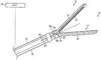
조직을 치료 및/또는 파괴하기 위해 조직에 전기 에너지를 인가하기 위한 전기수술용 장치는 또한 수술적 시술에서 점점 더 확대되는 응용들을 발견하고 있다. 전기수술용 장치는 핸드피스 및 원위에 장착된 단부 작동기(예컨대, 하나 이상의 전극)를 갖는 기구를 포함할 수 있다. 단부 작동기는 전류를 조직 내에 도입하도록 조직에 맞대어져 위치될 수 있다. 전기수술용 장치는 양극(bipolar) 또는 단극(monopolar) 동작을 위해 구성될 수 있다. 양극 동작 동안, 단부 작동기의 활성 전극 및 반환 전극 각각에 의해 전류가 조직 내에 도입되고 조직으로부터 반환된다. 단극 동작 동안에는, 전류가 단부 작동기의 활성 전극에 의해 조직 내에 도입되고, 환자의 신체 상에 별개로 위치된 반환 전극(예컨대, 접지 패드)을 통해 반환된다. 조직을 통한 전류 흐름에 의해 생성되는 열은 조직 내에 및/또는 조직들 사이에 지혈 봉합부를 형성할 수 있으며, 따라서 예를 들어 혈관을 봉합하는 데 특히 유용할 수 있다. 전기수술용 장치의 단부 작동기는 또한 조직을 절개하도록 조직 및 전극들에 대해 이동가능한 절단 부재를 포함할 수 있다.Electrosurgical devices for applying electrical energy to tissue to treat and / or destroy tissue also find applications that are increasingly widening in surgical procedures. Electrosurgical devices may include a handpiece and a device having an end effector (e.g., one or more electrodes) mounted on a circle. The end effector may be positioned against the tissue to introduce current into the tissue. The electrosurgical device may be configured for bipolar or monopolar operation. During bipolar operation, current is introduced into and returned from tissue by the active and return electrodes of the end effector, respectively. During unipolar operation, current is introduced into the tissue by the active electrode of the end effector and returned through a return electrode (e. G., A ground pad) located separately on the patient ' s body. The heat generated by the current flow through the tissue can form hemostatic sutures within the tissue and / or between tissues, and thus may be particularly useful for sealing blood vessels, for example. The end effector of the electrosurgical device may also include a cutting member movable relative to the tissue and electrodes to cut tissue.
전기수술용 장치에 의해 인가되는 전기 에너지는 핸드피스와 통신하는 발생기에 의해 기구로 전달될 수 있다. 전기 에너지는 무선 주파수(radio frequency, "RF") 에너지의 형태일 수 있다. RF 에너지는 300 ㎑ 내지 1 ㎒의 주파수 범위 내일 수 있는 전기 에너지의 형태이다. 그의 동작 동안, 전기수술용 장치는 조직을 통해 저 주파수 RF 에너지를 전달할 수 있고, 이는 이온성 진동(ionic agitation) 또는 마찰, 사실상 저항성 가열을 일으켜서, 조직의 온도를 증가시킨다. 뚜렷한 경계가 영향받은 조직과 주변 조직 사이에 생성될 수 있기 때문에, 외과의는 비-타겟 인접 조직을 희생시키지 않고서 높은 정밀도 및 제어 레벨로 동작시킬 수 있다. RF 에너지의 낮은 동작 온도는 연조직을 제거, 수축 또는 스컬프팅(sculpting)함과 동시에 혈관을 봉합하는 데 유용할 수 있다. RF 에너지는 주로 콜라겐으로 구성되고 열과 접촉될 때 수축하는 결합 조직(connective tissue)에 대해 특히 잘 작용할 수 있다.The electrical energy applied by the electrosurgical device may be transmitted to the device by a generator in communication with the handpiece. The electrical energy may be in the form of radio frequency ("RF") energy. RF energy is a form of electrical energy that can be in the frequency range of 300 kHz to 1 MHz. During its operation, the electrosurgical device can deliver low frequency RF energy through the tissue, causing ionic agitation or friction, virtually resistive heating, thereby increasing the temperature of the tissue. Because distinct boundaries can be created between the affected tissue and the surrounding tissue, the surgeon can operate at high precision and control levels without sacrificing non-targeted adjacent tissue. The low operating temperature of the RF energy can be useful for suturing vessels at the same time as removing, shrinking, or sculpting soft tissue. RF energy can work particularly well for connective tissue that consists primarily of collagen and contracts when in contact with heat.
그들 고유의 구동 신호, 감지 및 피드백 요구로 인해, 초음파 및 전기수술용 장치는 일반적으로 상이한 발생기들을 필요로 하였다. 또한, 기구가 일회용이거나 핸드피스와 상호교환가능한 경우, 초음파 및 전기수술용 발생기는 사용되는 특정한 기구 구성을 인식하고 그에 따라 제어 및 진단 프로세스를 최적화하는 그들의 능력 면에서 제한된다. 더욱이, 특히 보다 높은 전압들 및 주파수들이 사용되는 경우에 발생기의 비-절연 회로와 환자-절연 회로 사이의 용량 커플링이 허용가능하지 않은 누설 전류 레벨에 대한 환자의 노출을 초래할 수 있다.Due to their inherent drive signal, sensing and feedback requirements, ultrasound and electrosurgical devices generally required different generators. In addition, ultrasound and electrosurgical generators are limited in their ability to recognize the particular instrument configuration used and optimize the control and diagnostic process accordingly if the instrument is disposable or interchangeable with the handpiece. Moreover, capacitive coupling between the non-insulated circuit and the patient-insulated circuit of the generator, especially when higher voltages and frequencies are used, can result in exposure of the patient to an unacceptable leakage current level.
또한, 그들 고유의 구동 신호, 감지 및 피드백 요구로 인해, 초음파 및 전기수술용 장치들은 일반적으로 상이한 발생기들에 대한 상이한 사용자 인터페이스들을 필요로 하였다. 그러한 종래의 초음파 및 전기수술용 장치들에서, 하나의 사용자 인터페이스는 초음파 기구와 함께 사용하도록 구성되는 반면, 다른 사용자 인터페이스는 전기수술용 기구와 함께 사용하도록 구성될 수 있다. 그러한 사용자 인터페이스들은 핸드 활성화 스위치들 및/또는 풋 활성화 스위치들과 같은 핸드 및/또는 풋 활성화 사용자 인터페이스들을 포함한다. 초음파 및 전기수술용 기구들 둘 모두와 함께 사용하기 위한 조합된 발생기들의 다양한 실시예들이 후속의 개시 내용에서 고려되기 때문에, 초음파 및/또는 전기수술용 기구 발생기들 둘 모두와 함께 동작하도록 구성된 추가적인 사용자 인터페이스들이 또한 고려된다.In addition, due to their inherent drive signal, sensing and feedback requirements, ultrasound and electrosurgical devices generally required different user interfaces for different generators. In such conventional ultrasonic and electrosurgical devices, one user interface may be configured for use with an ultrasonic device, while another user interface may be configured for use with an electrosurgical instrument. Such user interfaces include hand and / or foot activated user interfaces such as hand activation switches and / or foot activation switches. As various embodiments of the combined generators for use with both ultrasound and electrosurgical instruments are contemplated in the following disclosure, additional users configured to operate with both ultrasonic and / or electrosurgical instrument generators Interfaces are also considered.
초음파 및/또는 전기수술용 기구 중 어느 하나의 동작 모드 또는 상태를 나타내는 피드백을 제공하기 위해 후속의 개시 내용 안에서는, 사용자에게든지 또는 다른 기계에게든지 간에, 피드백을 제공하기 위한 추가적인 사용자 인터페이스들이 고려된다. 조합 초음파 및/또는 전기수술용 기구를 동작시키기 위한 사용자 및/또는 기계 피드백을 제공하는 것은 사용자에게 감각적 피드백을 제공하고 기계에게 전기/기계/전기-기계 피드백을 제공하는 것을 필요로 할 것이다. 조합된 초음파 및/또는 전기수술용 기구들에서 사용하기 위한 시각 피드백 장치(예컨대, LCD 디스플레이 스크린, LED 지시기), 청각 피드백 장치(예컨대, 스피커, 버저) 또는 촉각 피드백 장치(예컨대, 햅틱 액추에이터(haptic actuator))를 포함하는 피드백 장치들이 후속의 개시 내용에서 고려된다.Additional user interfaces for providing feedback, either to the user or to another machine, are contemplated in a subsequent disclosure to provide feedback indicating the mode or mode of operation of any of the ultrasonic and / or electrosurgical instruments. Providing user and / or machine feedback to operate combination ultrasound and / or electrosurgical instruments may require providing sensory feedback to the user and providing electrical / mechanical / electro-mechanical feedback to the machine. (E. G., A speaker, a buzzer) or a tactile feedback device (e. G., A haptic actuator (e. G., A haptic actuator)) for use in combined ultrasound and / actuators) are contemplated in the following disclosure.
구동 신호를 수술용 장치에 전달하기 위한 발생기의 다양한 실시예가 개시된다. 다양한 실시예에 따르면, 발생기는 시간-가변 구동 신호 파형을 수신하기 위한 전력 증폭기를 포함할 수 있다. 구동 신호 파형은 복수의 구동 신호 파형 샘플 중 적어도 일부의 디지털-아날로그 변환에 의해 생성될 수 있다. 전력 증폭기의 출력은 구동 신호를 생성하기 위한 것일 수 있다. 구동 신호는 초음파 수술용 장치로 전달될 제1 구동 신호, 전기수술용 장치로 전달될 제2 구동 신호 중 하나를 포함할 수 있다. 발생기는 또한 구동 신호가 수술용 장치로 전달될 때 구동 신호의 전류 및 전압의 샘플들을 생성하기 위한 샘플링 회로를 포함할 수 있다. 샘플들의 생성은 구동 신호 파형 샘플들의 디지털-아날로그 변환과 동기화될 수 있어서, 구동 신호 파형 샘플의 각각의 디지털-아날로그 변환에 대해, 샘플링 회로가 전류 및 전압 샘플들의 대응 세트를 생성한다. 발생기는 또한 적어도 하나의 장치를 포함할 수 있으며, 적어도 하나의 장치는 각각의 구동 신호 파형 샘플 및 전류 및 전압 샘플들의 대응 세트에 대해 전류 및 전압 샘플들을 적어도 하나의 장치의 메모리에 저장하여, 저장된 샘플들을 구동 신호 파형 샘플과 연관시키도록 프로그래밍된다. 적어도 하나의 장치는 또한, 구동 신호가 제1 구동 신호를 포함할 때, 저장된 전류 및 전압 샘플들에 기초하여 초음파 수술용 장치의 운동 분로 전류 샘플을 결정하고, 운동 분로 전류 샘플과, 타겟 파형을 정의하는 복수의 타겟 샘플로부터 선택된 타겟 샘플(이 타겟 샘플은 구동 신호 파형 샘플에 기초하여 선택됨)을 비교하고, 타겟 샘플과 운동 분로 전류 샘플 사이의 진폭 에러를 결정하고, 구동 신호 파형 샘플을 수정하여, 타겟 샘플과 수정된 구동 신호 파형 샘플과 연관된 전류 및 전압 샘플들에 기초하는 후속 운동 분로 전류 샘플 사이에 결정되는 진폭 에러가 감소되게 하도록 프로그래밍될 수 있다.Various embodiments of a generator for delivering a drive signal to a surgical device are disclosed. According to various embodiments, the generator may include a power amplifier for receiving the time-varying drive signal waveform. The drive signal waveform may be generated by digital-to-analog conversion of at least some of the plurality of drive signal waveform samples. The output of the power amplifier may be for generating a drive signal. The drive signal may comprise a first drive signal to be delivered to the ultrasound surgical device, or a second drive signal to be delivered to the electrosurgical device. The generator may also include a sampling circuit for generating samples of the current and voltage of the drive signal when the drive signal is delivered to the surgical device. The generation of samples can be synchronized with the digital-to-analog conversion of the driving signal waveform samples so that for each digital-to-analog conversion of the driving signal waveform samples, the sampling circuit generates a corresponding set of current and voltage samples. The generator may also include at least one device, wherein the at least one device stores current and voltage samples for a respective set of drive signal waveform samples and current and voltage samples in a memory of at least one device, And to associate the samples with the drive signal waveform samples. The at least one apparatus also determines a kinetic shunting current sample of the device for ultrasound operation based on the stored current and voltage samples when the drive signal comprises the first drive signal, Comparing the target sample selected from a plurality of target samples that are defining (the target sample is selected based on the drive signal waveform sample), determining an amplitude error between the target sample and the motion shunt current sample, modifying the drive signal waveform sample , The amplitude error determined between the target sample and the subsequent kinetic shunt current sample based on the current and voltage samples associated with the modified drive signal waveform sample may be programmed to be reduced.
다양한 실시예에 따르면, 발생기는 메모리, 및 구동 신호를 합성하는 데 이용되는 복수의 구동 신호 파형 샘플 각각에 대해 구동 신호의 전류 및 전압 샘플들의 대응 세트를 수신하기 위해 메모리에 커플링된 장치를 포함할 수 있다. 각각의 구동 신호 파형 샘플 및 전류 및 전압 샘플들의 대응 세트에 대해, 장치는 샘플들을 장치의 메모리에 저장하여, 저장된 샘플들과 구동 신호 파형 샘플을 연관시킬 수 있다. 또한, 각각의 구동 신호 파형 샘플 및 전류 및 전압 샘플들의 대응 세트에 대해, 장치는 구동 신호가 초음파 수술용 장치로 전달될 제1 구동 신호를 포함할 때, 저장된 샘플들에 기초하여 초음파 수술용 장치의 운동 분로 전류 샘플을 결정하고, 운동 분로 전류 샘플과, 타겟 파형을 정의하는 복수의 타겟 샘플로부터 구동 신호 파형 샘플에 기초하여 선택된 타겟 샘플을 비교하고, 타겟 샘플과 운동 분로 전류 샘플 사이의 진폭 에러를 결정하고, 구동 신호 파형 샘플을 수정하여, 타겟 샘플과 수정된 구동 신호 파형 샘플과 연관된 전류 및 전압 샘플들에 기초하는 후속 운동 분로 전류 샘플 사이에 결정되는 진폭 에러가 감소되게 할 수 있다.According to various embodiments, the generator includes a memory and a device coupled to the memory for receiving a corresponding set of current and voltage samples of the drive signal for each of the plurality of drive signal waveform samples used to synthesize the drive signal can do. For each of the drive signal waveform samples and the corresponding set of current and voltage samples, the device can store the samples in the memory of the device to associate the drive signal waveform samples with the stored samples. In addition, for each of the drive signal waveform samples and the corresponding set of current and voltage samples, the device may be configured to generate a drive signal based on the stored samples when the drive signal comprises a first drive signal to be delivered to the device for ultrasound, Comparing the motion shunt current sample with a target sample selected based on drive signal waveform samples from a plurality of target samples defining a target waveform and generating an amplitude error signal between the target sample and the motion shunt current sample, And modify the drive signal waveform samples to reduce the amplitude error determined between the target sample and the subsequent kinetic shunt current samples based on the current and voltage samples associated with the modified drive signal waveform samples.
다양한 실시예에 따르면, 트랜스듀서 구동 신호의 복수의 주파수에 걸쳐 초음파 수술용 장치의 초음파 트랜스듀서 내의 운동 분로 전류를 결정하기 위한 방법들이 또한 개시된다. 일 실시예에서, 방법은 트랜스듀서 구동 신호의 복수의 주파수 각각에서, 트랜스듀서 구동 신호의 전류 및 전압을 오버샘플링(oversampling)하는 단계, 프로세서에 의해 전류 및 전압 샘플들을 수신하는 단계, 및 프로세서에 의해 전류 및 전압 샘플들, 초음파 트랜스듀서의 정적 용량 및 트랜스듀서 구동 신호의 주파수에 기초하여 운동 분로 전류를 결정하는 단계를 포함할 수 있다.According to various embodiments, methods are also disclosed for determining a kinetic shunt current in an ultrasonic transducer of an ultrasonic surgical apparatus over a plurality of frequencies of a transducer drive signal. In one embodiment, the method includes oversampling the current and voltage of the transducer drive signal at each of a plurality of frequencies of the transducer drive signal, receiving current and voltage samples by the processor, Determining the kinetic shunt current based on the current and voltage samples, the static capacitance of the ultrasonic transducer, and the frequency of the transducer drive signal.
다양한 실시예에 따르면, 수술용 장치의 초음파 트랜스듀서 내의 운동 분로 전류의 파형 형상을 제어하기 위한 방법들이 또한 개시된다. 일 실시예에서, 방법은 직접 디지털 합성(direct digital synthesis, DDS) 알고리즘을 사용하여 탐색표(look-up table, LUT)에 저장된 구동 신호 파형 샘플들을 선택적으로 회수함으로써 트랜스듀서 구동 신호를 생성하는 단계, 트랜스듀서 구동 신호가 수술용 장치로 전달될 때 트랜스듀서 구동 신호의 전류 및 전압의 샘플들을 생성하는 단계, 전류 및 전압 샘플들, 초음파 트랜스듀서의 정적 용량 및 트랜스듀서 구동 신호의 주파수에 기초하여 운동 분로 전류의 샘플들을 결정하는 단계, 운동 분로 전류의 각각의 샘플과 타겟 파형의 각각의 타겟 샘플을 비교하여 에러 진폭을 결정하는 단계, 및 LUT에 저장된 구동 신호 파형 샘플들을 수정하여, 운동 분로 전류의 후속 샘플들과 각각의 타겟 샘플들 사이의 진폭 에러가 감소되게 하는 단계를 포함할 수 있다.According to various embodiments, methods for controlling the waveform shape of a kinetic shunt current in an ultrasonic transducer of a surgical device are also disclosed. In one embodiment, the method includes generating a transducer drive signal by selectively retrieving drive signal waveform samples stored in a look-up table (LUT) using a direct digital synthesis (DDS) algorithm Generating samples of the current and voltage of the transducer drive signal as the transducer drive signal is delivered to the surgical device, based on the current and voltage samples, the static capacitance of the ultrasonic transducer and the frequency of the transducer drive signal Comparing the respective samples of the motion shunt current with respective target samples of the target waveform to determine error amplitudes, and modifying the drive signal waveform samples stored in the LUT, And to cause the amplitude error between subsequent samples of each target sample to be reduced.
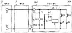
다양한 실시예에 따르면, 구동 신호를 수술용 장치에 제공하기 위한 수술용 발생기는 제1 변압기(transformer) 및 제2 변압기를 포함할 수 있다. 제1 변압기는 제1 주 권선 및 제1 보조 권선을 포함할 수 있다. 제2 변압기는 제2 주 권선 및 제2 보조 권선을 포함할 수 있다. 수술용 발생기는 구동 신호를 생성하기 위한 발생기 회로를 추가로 포함할 수 있다. 발생기 회로는 제1 주 권선에 전기적으로 커플링되어, 제1 주 권선 양단에 구동 신호를 제공할 수 있다. 수술용 발생기는 또한 발생기 회로로부터 전기적으로 절연된 환자측 회로를 포함할 수 있다. 환자측 회로는 제1 보조 권선에 전기적으로 커플링될 수 있다. 또한, 환자측 회로는 구동 신호를 수술용 장치에 제공하기 위한 제1 출력 라인 및 제2 출력 라인을 포함할 수 있다. 또한, 수술용 발생기는 커패시터(capacitor)를 포함할 수 있다. 커패시터 및 제2 보조 권선은 제1 출력 라인과 접지 사이에 직렬로 전기적으로 커플링될 수 있다.According to various embodiments, a surgical generator for providing a drive signal to a surgical device may comprise a first transformer and a second transformer. The first transformer may include a first main winding and a first auxiliary winding. The second transformer may include a second main winding and a second auxiliary winding. The surgical generator may further include a generator circuit for generating a drive signal. The generator circuit may be electrically coupled to the first main winding to provide a drive signal across the first main winding. The surgical generator may also include a patient circuit that is electrically isolated from the generator circuit. The patient circuit may be electrically coupled to the first auxiliary winding. In addition, the patient side circuit may include a first output line and a second output line for providing a driving signal to the surgical apparatus. In addition, the surgical generator may include a capacitor. The capacitor and the second auxiliary winding may be electrically coupled in series between the first output line and ground.
다양한 실시예에 따르면, 구동 신호를 수술용 장치에 제공하기 위한 수술용 발생기는 제1 변압기, 환자측 회로, 및 커패시터를 포함할 수 있다. 제1 변압기는 주 권선, 제1 보조 권선 및 제2 보조 권선을 포함할 수 있다. 주 권선에 대한 제1 보조 권선의 극성은 제2 보조 권선의 극성과 반대일 수 있다. 발생기 회로는 구동 신호를 생성할 수 있으며, 제1 주 권선에 전기적으로 커플링되어, 제1 주 권선 양단에 구동 신호를 제공할 수 있다. 환자측 회로는 발생기 회로로부터 전기적으로 절연될 수 있으며, 제1 보조 권선에 전기적으로 커플링될 수 있다. 또한, 환자측 회로는 구동 신호를 수술용 장치에 제공하기 위한 제1 출력 라인 및 제2 출력 라인을 포함할 수 있다. 커패시터 및 제2 보조 권선은 제1 출력 라인과 접지 사이에 직렬로 전기적으로 커플링될 수 있다.According to various embodiments, a surgical generator for providing a drive signal to a surgical device may comprise a first transformer, a patient circuit, and a capacitor. The first transformer may include a main winding, a first auxiliary winding, and a second auxiliary winding. The polarity of the first auxiliary winding to the main winding may be opposite to the polarity of the second auxiliary winding. The generator circuit may generate a drive signal and may be electrically coupled to the first main winding to provide a drive signal across the first main winding. The patient circuit can be electrically isolated from the generator circuit and can be electrically coupled to the first auxiliary winding. In addition, the patient side circuit may include a first output line and a second output line for providing a driving signal to the surgical apparatus. The capacitor and the second auxiliary winding may be electrically coupled in series between the first output line and ground.
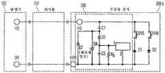
다양한 실시예에 따르면, 구동 신호를 수술용 장치에 제공하기 위한 수술용 발생기는 제1 변압기, 발생기 회로, 환자측 회로 및 커패시터를 포함할 수 있다. 제1 변압기는 주 권선 및 보조 권선을 포함할 수 있다. 발생기 회로는 구동 신호를 생성할 수 있으며, 제1 주 권선에 전기적으로 커플링되어, 제1 주 권선 양단에 구동 신호를 제공할 수 있다. 환자측 회로는 발생기 회로로부터 전기적으로 절연될 수 있으며, 보조 권선에 전기적으로 커플링될 수 있다. 또한, 환자측 회로는 구동 신호를 수술용 장치에 제공하기 위한 제1 출력 라인 및 제2 출력 라인을 포함할 수 있다. 커패시터는 주 권선에 그리고 제1 출력 라인에 전기적으로 커플링될 수 있다.According to various embodiments, a surgical generator for providing a drive signal to a surgical device may include a first transformer, a generator circuit, a patient circuit, and a capacitor. The first transformer may include a main winding and an auxiliary winding. The generator circuit may generate a drive signal and may be electrically coupled to the first main winding to provide a drive signal across the first main winding. The patient circuit may be electrically isolated from the generator circuit and electrically coupled to the auxiliary winding. In addition, the patient side circuit may include a first output line and a second output line for providing a driving signal to the surgical apparatus. The capacitor may be electrically coupled to the primary winding and to the first output line.
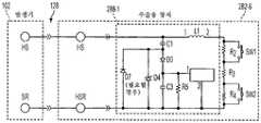
다양한 실시예에 따르면, 구동 신호를 수술용 장치에 제공하기 위한 수술용 발생기는 제1 변압기, 발생기 회로, 환자측 회로는 물론, 제1, 제2 및 제3 커패시터를 포함할 수 있다. 제1 변압기는 주 권선 및 보조 권선을 포함할 수 있다. 발생기 회로는 구동 신호를 생성할 수 있으며, 제1 주 권선에 전기적으로 커플링되어, 제1 주 권선 양단에 구동 신호를 제공할 수 있다. 환자측 회로는 발생기 회로로부터 전기적으로 절연될 수 있으며, 보조 권선에 전기적으로 커플링될 수 있다. 또한, 환자측 회로는 구동 신호를 수술용 장치에 제공하기 위한 제1 출력 라인 및 제2 출력 라인을 포함할 수 있다. 제1 커패시터의 제1 전극은 주 권선에 전기적으로 커플링될 수 있다. 제2 커패시터의 제1 전극은 제1 출력 라인에 전기적으로 커플링될 수 있고, 제2 커패시터의 제2 전극은 제1 커패시터의 제2 전극에 전기적으로 커플링될 수 있다. 제3 커패시터의 제1 전극은 제1 커패시터의 제2 전극 및 제2 커패시터의 제2 전극에 전기적으로 커플링될 수 있다. 제3 커패시터의 제2 전극은 접지에 전기적으로 커플링될 수 있다.According to various embodiments, a surgical generator for providing a drive signal to a surgical device may include a first transformer, a generator circuit, a patient circuit, as well as first, second and third capacitors. The first transformer may include a main winding and an auxiliary winding. The generator circuit may generate a drive signal and may be electrically coupled to the first main winding to provide a drive signal across the first main winding. The patient circuit may be electrically isolated from the generator circuit and electrically coupled to the auxiliary winding. In addition, the patient side circuit may include a first output line and a second output line for providing a driving signal to the surgical apparatus. The first electrode of the first capacitor may be electrically coupled to the main winding. The first electrode of the second capacitor may be electrically coupled to the first output line and the second electrode of the second capacitor may be electrically coupled to the second electrode of the first capacitor. The first electrode of the third capacitor may be electrically coupled to the second electrode of the first capacitor and the second electrode of the second capacitor. The second electrode of the third capacitor may be electrically coupled to ground.
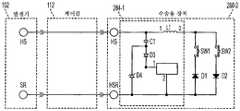
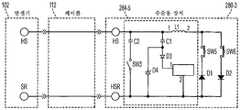
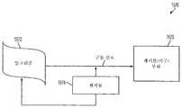
다양한 실시예에 따르면, 수술용 장치를 위한 제어 회로가 또한 개시된다. 일 실시예에서, 제어 회로는 적어도 하나의 제1 스위치를 포함하는 제1 회로부를 포함할 수 있다. 제1 회로부는 도체 쌍을 통해 수술용 발생기와 통신할 수 있다. 제어 회로는 또한 데이터 회로 요소를 포함하는 제2 회로부를 포함할 수 있다. 데이터 회로 요소는 수술용 장치의 기구 내에 배치되어 데이터를 전송 또는 수신할 수 있다. 데이터 회로 요소는 도체 쌍 중 적어도 하나의 도체를 통해 수술용 발생기와의 데이터 통신을 구현할 수 있다.According to various embodiments, a control circuit for a surgical device is also disclosed. In one embodiment, the control circuit may include a first circuit portion including at least one first switch. The first circuitry may communicate with the surgical generator via a conductor pair. The control circuit may also include a second circuit portion including a data circuit element. The data circuit element may be disposed within the device of the surgical device to transmit or receive data. The data circuit element may implement data communication with the surgical generator through at least one conductor of the pair of conductors.
다양한 실시예에 따르면, 제어 회로는 적어도 하나의 제1 스위치를 포함하는 제1 회로부를 포함할 수 있다. 제1 회로부는 도체 쌍을 통해 수술용 발생기와 통신할 수 있다. 제어 회로는 또한 데이터 회로 요소를 포함하는 제2 회로부를 포함할 수 있다. 데이터 회로 요소는 수술용 장치의 기구 내에 배치되어 데이터를 전송 또는 수신할 수 있다. 데이터 회로 요소는 도체 쌍 중 적어도 하나의 도체를 통해 수술용 발생기와의 데이터 통신을 구현할 수 있다. 제1 회로부는 제1 주파수 대역에서 수술용 발생기로부터 전송되는 제1 질의 신호(interrogation signal)를 수신할 수 있다. 데이터 회로 요소는 제2 주파수 대역에서 전송되는 진폭 변조 통신 프로토콜(amplitude-modulated communication protocol)을 사용하여 수술용 발생기와 통신할 수 있다. 제2 주파수 대역은 제1 주파수 대역보다 높을 수 있다.According to various embodiments, the control circuit may include a first circuit portion including at least one first switch. The first circuitry may communicate with the surgical generator via a conductor pair. The control circuit may also include a second circuit portion including a data circuit element. The data circuit element may be disposed within the device of the surgical device to transmit or receive data. The data circuit element may implement data communication with the surgical generator through at least one conductor of the pair of conductors. The first circuitry may receive a first interrogation signal transmitted from the surgical generator in the first frequency band. The data circuit element may communicate with the surgical generator using an amplitude-modulated communication protocol transmitted in the second frequency band. The second frequency band may be higher than the first frequency band.
다양한 실시예에 따르면, 제어 회로는 적어도 하나의 제1 스위치를 포함하는 제1 회로부를 포함할 수 있다. 제1 회로부는 도체 쌍을 통해 수술용 발생기로부터 전송되는 제1 질의 신호를 수신할 수 있다. 제어 회로는 또한 장치의 기구 내에 배치된 저항 요소 및 유도 요소 중 적어도 하나를 포함하는 제2 회로부를 포함할 수 있다. 제2 회로부는 도체 쌍을 통해 수술용 발생기로부터 전송되는 제2 질의 신호를 수신할 수 있다. 제2 회로부는 제1 회로부로부터 주파수-대역 분리될 수 있다. 제1 회로부를 통해 수신될 때, 제1 질의 신호의 특성은 적어도 하나의 제1 스위치의 상태를 나타낼 수 있다. 제2 회로부를 통해 수신될 때, 제2 질의 신호의 특성은 장치의 기구를 고유하게 식별할 수 있다.According to various embodiments, the control circuit may include a first circuit portion including at least one first switch. The first circuitry may receive a first query signal transmitted from the surgical generator through the conductor pair. The control circuit may also include a second circuit portion including at least one of a resistive element and an inductive element disposed within the device's mechanism. The second circuitry may receive a second query signal transmitted from the surgical generator through the conductor pair. The second circuit portion may be frequency-band separated from the first circuit portion. When received via the first circuitry, the characteristics of the first query signal may indicate the state of the at least one first switch. When received via the second circuitry, the characteristics of the second query signal may uniquely identify the device's mechanism.
다양한 실시예에 따르면, 제어 회로는 제1 스위치 네트워크 및 제2 스위치 네트워크를 포함하는 제1 회로부를 포함할 수 있다. 제1 스위치 네트워크는 적어도 하나의 제1 스위치를 포함할 수 있고, 제2 스위치 네트워크는 적어도 하나의 제2 스위치를 포함할 수 있다. 제1 회로부는 도체 쌍을 통해 수술용 발생기와 통신할 수 있다. 제어 회로는 또한 데이터 회로 요소를 포함하는 제2 회로부를 포함할 수 있다. 데이터 회로 요소는 수술용 장치의 기구 내에 배치될 수 있고, 데이터를 전송 또는 수신할 수 있다. 데이터 회로 요소는 도체 쌍 중 적어도 하나의 도체를 통해 수술용 발생기와 데이터 통신할 수 있다.According to various embodiments, the control circuit may include a first circuit portion including a first switch network and a second switch network. The first switch network may comprise at least one first switch, and the second switch network may comprise at least one second switch. The first circuitry may communicate with the surgical generator via a conductor pair. The control circuit may also include a second circuit portion including a data circuit element. The data circuit element may be disposed within the device of the surgical device and may transmit or receive data. The data circuit element may be in data communication with the surgical generator through at least one conductor of the pair of conductors.
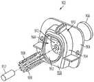
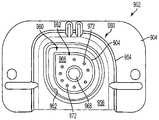
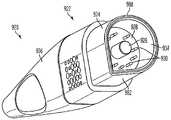
다양한 실시예에 따르면, 구동 신호를 수술용 장치에 제공하기 위한 수술용 발생기는 개구를 갖는 수술용 발생기 본체를 포함할 수 있다. 수술용 발생기는 또한 개구 내에 위치된 리셉터클 조립체(receptacle assembly)를 포함할 수 있다. 리셉터클 조립체는 리셉터클 본체, 및 내부 벽 및 외부 벽을 갖는 플랜지(flange)를 포함할 수 있다. 내부 벽은 적어도 하나의 곡선형 섹션 및 적어도 하나의 직선형 섹션으로 구성될 수 있다. 내부 벽은 공동을 한정할 수 있다. 중앙 돌출 부분이 공동 내에 위치될 수 있으며, 복수의 소켓(socket) 및 자석을 포함할 수 있다. 중앙 돌출 부분의 외부 주연부가 적어도 하나의 곡선형 섹션 및 적어도 하나의 직선형 섹션을 포함할 수 있다.According to various embodiments, a surgical generator for providing a drive signal to a surgical device may include a surgical generator body having an aperture. The surgical generator may also include a receptacle assembly positioned within the opening. The receptacle assembly may include a receptacle body, and a flange having an inner wall and an outer wall. The inner wall may comprise at least one curved section and at least one straight section. The inner wall may define a cavity. The central protruding portion may be located within the cavity, and may include a plurality of sockets and magnets. The outer periphery of the central protruding portion may include at least one curved section and at least one straight section.
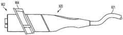
다양한 실시예에 따르면, 수술용 기구는 전기 커넥터 조립체를 포함할 수 있다. 전기 커넥터 조립체는 중앙 공동을 한정하는 플랜지 및 중앙 공동 내로 연장하는 자기적으로 양립가능한 핀(magnetically compatible pin)을 포함할 수 있다. 전기 커넥터 조립체는 회로 기판 및 회로 기판에 커플링되는 복수의 전기 전도성 핀을 포함할 수 있다. 복수의 전기 전도성 핀 각각은 중앙 공동 내로 연장할 수 있다. 전기 커넥터 조립체는 변형 완화 부재(strain relief member) 및 부트(boot)를 추가로 포함할 수 있다.According to various embodiments, the surgical instrument may include an electrical connector assembly. The electrical connector assembly may include a flange defining a central cavity and a magnetically compatible pin extending into the central cavity. The electrical connector assembly may include a plurality of electrically conductive pins coupled to the circuit board and the circuit board. Each of the plurality of electrically conductive pins may extend into the central cavity. The electrical connector assembly may further include a strain relief member and a boot.
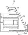
다양한 실시예에 따르면, 수술용 기구 시스템은 리셉터클 조립체를 포함하는 수술용 발생기를 포함할 수 있다. 리셉터클 조립체는 적어도 하나의 곡선형 섹션 및 적어도 하나의 직선형 부분을 포함할 수 있다. 수술용 기구 시스템은 커넥터 조립체를 포함하는 수술용 기구, 및 리셉터클 조립체 및 커넥터 조립체에 동작식으로 커플링되는 어댑터 조립체를 포함할 수 있다. 어댑터 조립체는 리셉터클 조립체와 접촉하는 원위 부분(distal portion)을 포함할 수 있다. 원위 부분은 플랜지를 포함할 수 있으며, 이때 플랜지는 적어도 하나의 곡선형 섹션 및 적어도 하나의 직선형 부분을 갖는다. 어댑터 조립체는 커넥터 조립체와 접촉하는 근위 부분(proximal portion)을 포함할 수 있다. 근위 부분은 커넥터 조립체의 적어도 일부분을 수용하도록 치수설정되는 공동을 한정할 수 있다. 어댑터 조립체는 회로 기판을 추가로 포함할 수 있다.According to various embodiments, the surgical instrument system may include a surgical generator including a receptacle assembly. The receptacle assembly may include at least one curved section and at least one straight section. The surgical instrument system may include a surgical instrument including a connector assembly, and an adapter assembly operatively coupled to the receptacle assembly and connector assembly. The adapter assembly may include a distal portion in contact with the receptacle assembly. The distal portion may include a flange, wherein the flange has at least one curved section and at least one straight section. The adapter assembly may include a proximal portion in contact with the connector assembly. The proximal portion may define a cavity dimensioned to receive at least a portion of the connector assembly. The adapter assembly may further include a circuit board.
다양한 실시예에 따르면, 다양한 수술적 목적을 달성하기 위한 방법들이 (예컨대, 수술용 기구와 함께) 사용될 수 있다. 예를 들어, 제1 전극 및 제2 전극을 통해 조직에 제공되는 전력을 제어하기 위한 방법은 제1 전극 및 제2 전극을 통해 조직에 구동 신호를 제공하는 단계 및 제1 전력 곡선(power curve)에 따라 감지된 조직 임피던스에 기초하여 구동 신호를 통해 조직에 제공되는 전력을 변조하는 단계를 포함할 수 있다. 제1 전력 곡선은 복수의 잠재적인 감지된 조직 임피던스 각각에 대해 제1 대응 전력을 정의할 수 있다. 방법은 또한 제1 전극 및 제2 전극을 통해 조직에 제공되는 총 에너지를 모니터링하는 단계를 포함할 수 있다. 총 에너지가 제1 에너지 임계치에 도달할 때, 방법은 조직의 임피던스가 제1 임피던스 임계치에 도달하였는지를 결정하는 단계를 포함할 수 있다. 방법은 조직의 임피던스가 제1 임피던스 임계치에 도달하지 않은 경우에, 제2 전력 곡선에 따라 감지된 조직 임피던스에 기초하여 구동 신호를 통해 조직에 제공되는 전력을 변조하는 단계를 추가로 포함할 수 있다. 제2 전력 곡선은 복수의 잠재적인 감지된 조직 임피던스 각각에 대해 제2 대응 전력을 정의할 수 있다.According to various embodiments, methods for achieving a variety of surgical objectives may be used (e. G., With a surgical instrument). For example, a method for controlling power provided to tissue through a first electrode and a second electrode includes providing a drive signal to tissue through a first electrode and a second electrode, and providing a first power curve, And modulating the power provided to the tissue via the drive signal based on the sensed tissue impedance according to the tissue impedance. The first power curve may define a first corresponding power for each of a plurality of potential sensed tissue impedances. The method may also include monitoring total energy provided to the tissue through the first electrode and the second electrode. When the total energy reaches a first energy threshold, the method may comprise determining if the impedance of the tissue has reached a first impedance threshold. The method may further include modulating power provided to the tissue via the drive signal based on the tissue impedance sensed according to the second power curve when the impedance of the tissue does not reach the first impedance threshold . The second power curve may define a second corresponding power for each of a plurality of potential sensed tissue impedances.
다양한 실시예에 따르면, 제1 전극 및 제2 전극을 통해 조직에 제공되는 전력을 제어하기 위한 방법은 제1 전극 및 제2 전극을 통해 조직에 구동 신호를 제공하는 단계 및 조직에 제공될 전력을 결정하는 단계를 포함할 수 있다. 결정하는 단계는 감지된 조직 임피던스의 지시를 수신하는 단계; 전력 곡선에 따라 감지된 조직 임피던스에 대한 제1 대응 전력을 결정하는 단계; 및 대응 전력에 승수를 곱하는 단계를 포함할 수 있다. 전력 곡선은 복수의 잠재적인 감지된 조직 임피던스 각각에 대한 대응 전력을 정의할 수 있다. 방법은 결정된 전력을 조직에 제공하기 위해 구동 신호를 변조하는 단계, 및 조직의 임피던스가 제1 임피던스 임계치에 도달하지 않은 경우에 조직에 제공되는 총 에너지의 함수로서 승수를 증가시키는 단계를 추가로 포함할 수 있다.According to various embodiments, a method for controlling power provided to tissue through a first electrode and a second electrode includes providing a drive signal to tissue through a first electrode and a second electrode, And a step of determining the number Determining comprises: receiving an indication of sensed tissue impedance; Determining a first corresponding power for the tissue impedance sensed according to a power curve; And multiplying the corresponding power by a multiplier. The power curve can define a corresponding power for each of a plurality of potential sensed tissue impedances. The method further includes modulating the drive signal to provide the determined power to the tissue and increasing the multiplier as a function of the total energy provided to the tissue when the impedance of the tissue has not reached the first impedance threshold can do.
다양한 실시예에 따르면, 제1 전극 및 제2 전극을 통해 조직에 제공되는 전력을 제어하기 위한 방법은 제1 전극 및 제2 전극을 통해 조직에 구동 신호를 제공하는 단계 및 조직에 제공될 전력을 결정하는 단계를 포함할 수 있다. 결정하는 단계는 감지된 조직 임피던스의 지시를 수신하는 단계; 전력 곡선에 따라 감지된 조직 임피던스에 대한 제1 대응 전력을 결정하는 단계; 및 대응 전력에 제1 승수를 곱하여, 결정된 전력을 구하는 단계를 포함할 수 있다. 전력 곡선은 복수의 잠재적인 감지된 조직 임피던스 각각에 대한 대응 전력을 정의할 수 있다. 방법은 결정된 전력을 조직에 제공하기 위해 구동 신호를 변조하는 단계, 및 제1 전극 및 제2 전극을 통해 조직에 제공되는 총 에너지를 모니터링하는 단계를 추가로 포함할 수 있다. 또한, 방법은, 총 에너지가 제1 에너지 임계치에 도달할 때, 조직의 임피던스가 제1 임피던스 임계치에 도달하였는지를 결정하는 단계; 및 조직의 임피던스가 제1 임피던스 임계치에 도달하지 않은 경우에, 제1 승수를 제1 양만큼 증가시키는 단계를 포함할 수 있다.According to various embodiments, a method for controlling power provided to tissue through a first electrode and a second electrode includes providing a drive signal to tissue through a first electrode and a second electrode, And a step of determining the number Determining comprises: receiving an indication of sensed tissue impedance; Determining a first corresponding power for the tissue impedance sensed according to a power curve; And multiplying the corresponding power by the first multiplier to obtain the determined power. The power curve can define a corresponding power for each of a plurality of potential sensed tissue impedances. The method may further include modulating the drive signal to provide the determined power to the tissue, and monitoring total energy provided to the tissue through the first and second electrodes. The method also includes determining if the impedance of the tissue has reached a first impedance threshold when the total energy reaches a first energy threshold; And increasing the first multiplier by a first amount if the impedance of the tissue has not reached the first impedance threshold.
다양한 실시예에 따르면, 수술용 장치를 통해 조직에 제공되는 전력을 제어하기 위한 방법은 구동 신호를 수술용 장치에 제공하는 단계; 조직의 임피던스의 지시를 수신하는 단계; 조직의 임피던스의 증가율을 계산하는 단계; 및 임피던스의 증가율을 사전결정된 상수 이상으로 유지하도록 구동 신호를 변조하는 단계를 포함할 수 있다.According to various embodiments, a method for controlling power provided to a tissue through a surgical device includes providing a drive signal to a surgical device; Receiving an indication of the impedance of the tissue; Calculating an increase rate of the impedance of the tissue; And modulating the drive signal to maintain the rate of increase in impedance above a predetermined constant.
다양한 실시예에 따르면, 수술용 장치를 통해 조직에 제공되는 전력을 제어하기 위한 방법은 구동 신호를 제공하는 단계를 포함할 수 있다. 구동 신호의 전력은 수술용 장치를 통해 조직에 제공되는 전력에 비례할 수 있다. 방법은 또한 조직의 임피던스의 지시들을 주기적으로 수신하는 단계 및 조직에 제1 복합 전력 곡선을 적용하는 단계를 포함할 수 있다. 조직에 제1 복합 전력 곡선을 적용하는 단계는 구동 신호 상에 제1 사전결정된 수의 제1 복합 전력 곡선 펄스들을 변조하는 단계; 및 제1 복합 전력 곡선 펄스들 각각에 대해, 조직의 임피던스의 제1 함수에 따라 펄스 전력 및 펄스 폭을 결정하는 단계를 포함할 수 있다. 방법은 또한 조직에 제2 복합 전력 곡선을 적용하는 단계를 포함할 수 있다. 조직에 제2 복합 전력 곡선을 적용하는 단계는 구동 신호 상에 적어도 하나의 제2 복합 전력 곡선 펄스를 변조하는 단계; 및 적어도 하나의 제2 복합 전력 곡선 펄스 각각에 대해, 조직의 임피던스의 제2 함수에 따라 펄스 전력 및 펄스 폭을 결정하는 단계를 포함할 수 있다.According to various embodiments, a method for controlling power provided to a tissue through a surgical device may comprise providing a drive signal. The power of the drive signal may be proportional to the power supplied to the tissue through the surgical device. The method may also include periodically receiving instructions of the impedance of the tissue and applying a first composite power curve to the tissue. Applying a first composite power curve to the tissue comprises modulating a first predetermined number of first composite power curve pulses on the drive signal; And for each of the first composite power curve pulses, determining a pulse power and a pulse width according to a first function of the impedance of the tissue. The method may also include applying a second composite power curve to the tissue. Applying a second composite power curve to the tissue comprises modulating at least one second composite power curve pulse on the drive signal; And for each of the at least one second composite power curve pulse, determining a pulse power and a pulse width according to a second function of the impedance of the tissue.
다양한 실시예에 따르면, 수술용 장치로의 구동 신호를 생성하는 발생기가 제공된다. 발생기는 초음파 장치를 구동하기 위한 제1 구동 신호를 생성하는 초음파 생성기 모듈, 전기수술용 장치를 구동하기 위한 제2 구동 신호를 생성하는 전기수술/무선 주파수(RF) 발생기 모듈, 및 초음파 발생기 모듈 및 전기수술/RF 발생기 모듈 각각에 커플링된 풋 스위치(foot switch)를 포함한다. 풋 스위치는 초음파 장치가 초음파 발생기 모듈에 커플링될 때 제1 모드에서 동작하도록 구성되고, 풋 스위치는 전기수술용 장치가 전기수술/RF 발생기 모듈에 커플링될 때 제2 모드에서 동작하도록 구성된다.According to various embodiments, there is provided a generator for generating a drive signal to a surgical device. The generator includes an ultrasound generator module for generating a first drive signal for driving the ultrasound device, an electrosurgical / radio frequency (RF) generator module for generating a second drive signal for driving the electrosurgical device, and an ultrasound generator module And a foot switch coupled to each of the electrosurgical / RF generator modules. The footswitch is configured to operate in a first mode when the ultrasound device is coupled to the ultrasound generator module, and the footswitch is configured to operate in a second mode when the electrosurgical device is coupled to the electrosurgical / RF generator module .
다양한 실시예에 따르면, 사전결정된 알고리즘에 따라 초음파 장치 및 전기수술용 장치 중 어느 하나의 동작에 따라 피드백을 제공하는 사용자 인터페이스를 포함하는 발생기가 제공된다.According to various embodiments, a generator is provided that includes a user interface that provides feedback according to the operation of either the ultrasound device or the electrosurgical device in accordance with a predetermined algorithm.
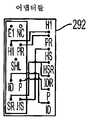
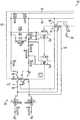
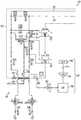
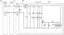
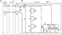
다양한 실시예에 따르면, 수술용 장치의 제어 회로가 제공된다. 제어 회로는 개방 상태와 폐쇄 상태 사이에 동작가능한 적어도 하나의 스위치에 커플링된 제1 회로부를 포함한다. 제1 회로부는 적어도 하나의 스위치의 상태를 결정하기 위해 제어 신호를 수신하도록 도체 쌍을 통해 수술용 발생기와 통신한다.According to various embodiments, a control circuit of a surgical device is provided. The control circuit includes a first circuit coupled to at least one switch operable between an open state and a closed state. The first circuitry communicates with the surgical generator via a conductor pair to receive a control signal to determine the state of the at least one switch.
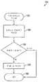
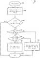
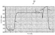
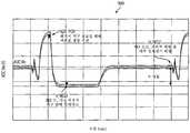
다양한 실시예에 따르면, 수술용 장치의 제어 회로가 제공된다. 제어 회로는 개방 상태와 폐쇄 상태 사이에 동작가능한 적어도 하나의 스위치에 커플링된 제1 회로부를 포함한다. 제1 회로부는 적어도 하나의 스위치의 상태를 결정하기 위해 입력 단자들로부터 제어 신호를 수신하도록 도체 쌍을 통해 수술용 발생기와 통신한다. 제어 신호는 양의 위상 및 음의 위상을 갖는다. 제1 트랜지스터가 입력 단자들 사이에 커플링되고, 제1 커패시터, 및 제1 저항기가 제1 커패시터와 직렬로 커플링된다. 제어 신호의 음의 위상 동안 제1 커패시터가 사전결정된 전압으로 충전되는 동안에 제1 트랜지스터는 컷오프 모드에 유지되고, 제어 신호의 음의 위상의 초기 부분 동안 제1 트랜지스터는 컷오프 모드로부터 포화 모드로 전이하고, 제1 커패시터가 제1 저항기를 통해 방전될 때까지 포화 모드에 유지된다. 제어 신호의 음의 위상의 최종 부분 동안 제1 커패시터 전압이 사전결정된 임계치 아래로 떨어질 때 제1 트랜지스터는 포화 모드로부터 컷오프 모드로 전이한다.According to various embodiments, a control circuit of a surgical device is provided. The control circuit includes a first circuit coupled to at least one switch operable between an open state and a closed state. The first circuitry communicates with the surgical generator via a conductor pair to receive a control signal from the input terminals to determine the state of the at least one switch. The control signal has a positive phase and a negative phase. A first transistor is coupled between the input terminals, and a first capacitor and a first resistor are coupled in series with the first capacitor. During the negative phase of the control signal, the first transistor is held in the cutoff mode while the first capacitor is charged to a predetermined voltage, and during the initial portion of the negative phase of the control signal the first transistor transitions from the cutoff mode to the saturation mode , And remains in the saturation mode until the first capacitor is discharged through the first resistor. When the first capacitor voltage falls below a predetermined threshold during the last portion of the negative phase of the control signal, the first transistor transitions from the saturation mode to the cut-off mode.
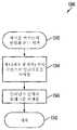
다양한 실시예에 따르면, 방법이 제공된다. 본 방법은 수술용 장치의 제어 회로에서 제어 신호를 수신하는 단계, 및 저항기의 값에 기초하여 적어도 하나의 스위치의 상태를 결정하는 단계를 포함한다. 제어 회로는 개방 상태와 폐쇄 상태 사이에 동작가능한 적어도 하나의 스위치에 커플링된 제1 회로부를 포함한다. 회로부는 제어 신호를 수신하기 위해 도체 쌍을 통해 수술용 발생기와 통신한다. 제1 회로부는 적어도 하나의 스위치에 커플링된 적어도 하나의 저항기를 포함한다.According to various embodiments, a method is provided. The method includes receiving a control signal in a control circuit of the surgical device, and determining the state of the at least one switch based on the value of the resistor. The control circuit includes a first circuit coupled to at least one switch operable between an open state and a closed state. The circuitry communicates with the surgical generator through a conductor pair to receive the control signal. The first circuitry includes at least one resistor coupled to the at least one switch.
다양한 실시예의 신규한 특징은 특히 첨부된 특허청구범위에 기재된다. 그러나, 설명된 실시예는 동작의 방법 및 조직화 둘 모두에 관하여, 첨부 도면과 관련하여 취해진 하기의 설명을 참조함으로써 가장 잘 이해될 수 있다.
<도 1>
도 1은 발생기 및 그와 함께 사용가능한 다양한 수술용 기구를 포함하는 수술용 시스템의 일 실시예를 예시하는 도면.
<도 2>
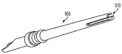
도 2는 절개 및/또는 봉합을 위해 사용될 수 있는 예시의 초음파 장치의 일 실시예를 예시하는 도면.
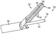
<도 3>
도 3은 도 2의 예시의 초음파 장치의 단부 작동기의 일 실시예를 예시하는 도면.
<도 4>
도 4는 절개 및 봉합을 위해 또한 사용될 수 있는 예시의 전기수술용 장치의 일 실시예를 예시하는 도면.
<도 5, 도 6 및 도 7>
도 5, 도 6 및 도 7은 도 4에 도시된 단부 작동기의 일 실시예를 예시하는 도면.
<도 8>
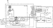
도 8은 도 1의 수술용 시스템의 다이어그램.
<도 9>
도 9는 일 실시예의 운동 분로 전류를 예시하는 모델.
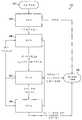
<도 10>
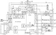
도 10은 일 실시예의 발생기 아키텍처의 구조도.
<도 11a 내지 도 11c>
도 11a 내지 도 11c는 일 실시예의 발생기 아키텍처의 기능도.
<도 12>
도 12는 일 실시예에서 입력 장치들을 모니터링하고 출력 장치들을 제어하기 위한 제어기를 예시하는 도면.
<도 13a 및 도 13b>
도 13a 및 도 13b는 발생기의 일 실시예의 구조적 및 기능적 양태들을 예시하는 도면.
<도 14 내지 도 32 및 도 33a 내지 도 33c>
도 14 내지 도 32 및 도 33a 내지 도 33c는 제어 회로의 실시예를 예시하는 도면.
<도 33d 내지 도 33i>
도 33d 내지 도 33i는 다양한 발생기와 다양한 수술용 기구를 연결하기 위한 케이블링 및 어댑터 구성의 실시예를 예시하는 도면.
<도 34>
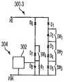
도 34는 누설 전류의 능동적인 제거를 위한 회로(300)의 일 실시예를 예시하는 도면.
<도 35>
도 35는 누설 전류의 능동적인 제거를 제공하도록 도 1의 발생기에 의해 구현될 수 있는 회로의 일 실시예를 예시하는 도면.
<도 36>
도 36은 누설 전류의 능동적인 제거를 제공하도록 도 1의 발생기에 의해 구현될 수 있는 회로의 대안적인 실시예를 예시하는 도면.
<도 37>
도 37은 누설 전류의 능동적인 제거를 제공하도록 도 1의 발생기에 의해 구현될 수 있는 회로의 대안적인 실시예를 예시하는 도면.
<도 38>
도 38은 누설 전류의 능동적인 제거를 제공하도록 도 1의 발생기에 의해 구현될 수 있는 회로의 또 다른 실시예를 예시하는 도면.
<도 39>
도 39는 누설 전류의 제거를 제공하도록 도 1의 발생기에 의해 구현될 수 있는 회로의 실시예를 예시하는 도면.
<도 40>
도 40은 누설 전류의 제거를 제공하도록 도 1의 발생기에 의해 구현될 수 있는 회로의 다른 실시예를 예시하는 도면.
<도 41>
도 41은 일 실시예의 리셉터클 및 커넥터 인터페이스를 예시하는 도면.
<도 42>
도 42는 일 실시예의 리셉터클 조립체의 분해 측면도.
<도 43>
도 43은 일 실시예의 커넥터 조립체의 분해 측면도.
<도 44>
도 44는 도 41에 도시된 리셉터클 조립체의 사시도.
<도 45>
도 45는 일 실시예의 리셉터클 조립체의 분해 사시도.
<도 46>
도 46은 일 실시예의 리셉터클 조립체의 정면도.
<도 47>
도 47은 일 실시예의 리셉터클 조립체의 측면도.
<도 48>
도 48은 일 실시예의 소켓의 확대도.
<도 49>
도 49는 일 실시예의 커넥터 조립체의 사시도.
<도 50>
도 50은 일 실시예의 커넥터 조립체의 분해 사시도.
<도 51>
도 51은 일 실시예의 커넥터 본체의 측면도.
<도 52>
도 52는 일 실시예의 커넥터 본체의 원위 단부의 사시도.
<도 53>
도 53은 일 실시예의 커넥터 본체의 근위 단부의 사시도.
<도 54>
도 54는 일 실시예의 철 핀(ferrous pin)을 예시하는 도면.
<도 55>
도 55는 일 실시예의 전기 전도성 핀 및 회로 기판을 예시하는 도면.
<도 56>
도 56은 일 실시예의 변형 완화 부재를 예시하는 도면.
<도 57>
도 57은 일 실시예의 부트를 예시하는 도면.
<도 58>
도 58은 다양한 비제한적인 실시예에 따른 2개의 어댑터 조립체를 예시하는 도면.
<도 59>
도 59는 일 실시예의 수술용 발생기를 예시하는 도면.
<도 60>
도 60은 일 실시예에서 어댑터 조립체에 연결된 커넥터 조립체를 예시하는 도면.
<도 61>
도 61은 일 실시예에서 수술용 발생기의 리셉터클 조립체 내로 삽입된 어댑터 조립체를 예시하는 도면.
<도 62>
도 62는 일 실시예에서 어댑터 조립체에 연결된 커넥터 조립체를 예시하는 도면.
<도 63>
도 63은 일 실시예의 발생기의 배면 패널의 사시도.
<도 64>
도 64는 일 실시예의 발생기의 배면 패널을 예시하는 도면.
<도 65 및 도 66>
도 65 및 도 66은 일 실시예의 발생기의 배면 패널의 상이한 부분들을 예시하는 도면.
<도 67>
도 67은 일 실시예에서 발생기를 제어하기 위한 신경망(neural network)을 예시하는 도면.
<도 68>
도 68은 일 실시예에서 발생기에 의해 제어되는 수술용 기구에 의해 출력되는 추정된 온도 대 측정된 온도를 예시하는 도면.
<도 69>
도 69는 예시의 전력 곡선을 도시하는 차트의 일 실시예를 예시하는 도면.
<도 70>
도 70은 하나 이상의 전력 곡선을 조직 바이트(tissue bite)에 적용하기 위한 프로세스 흐름의 일 실시예를 예시하는 도면.
<도 71>
도 71은 도 70의 프로세스 흐름과 관련하여 사용될 수 있는 예시의 전력 곡선을 도시하는 차트의 일 실시예를 예시하는 도면.
<도 72>
도 72는 도 70의 프로세스 흐름과 관련하여 사용될 수 있는 예시의 공통적인 형상의 전력 곡선을 도시하는 차트의 일 실시예를 예시하는 도면.
<도 73a>
도 73a는 새로운 조직 바이트에 작용하도록 도 1의 발생기의 디지털 장치에 의해 수행될 수 있는 루틴의 일 실시예를 예시하는 도면.
<도 73b>
도 73b는 조직 임피던스를 모니터링하도록 도 1의 발생기의 디지털 장치에 의해 수행될 수 있는 루틴의 일 실시예를 예시하는 도면.
<도 73c>
도 73c는 하나 이상의 전력 곡선을 조직 바이트에 제공하도록 도 1의 발생기의 디지털 장치에 의해 수행될 수 있는 루틴의 일 실시예를 예시하는 도면.
<도 74>
도 74는 하나 이상의 전력 곡선을 조직 바이트에 적용하기 위한 프로세스 흐름의 일 실시예를 예시하는 도면.
<도 75>
도 75는 도 1의 발생기에 의한 복합 부하 곡선의 선택 및 적용을 기술하는 블록 다이어그램의 일 실시예를 예시하는 도면.
<도 76>
도 76은 도 1의 발생기에 의해 구현되는 바와 같은, 도 75의 알고리즘의 일 실시예를 예시하는 프로세스 흐름을 도시하는 도면.
<도 77>
도 77은 제1 복합 부하 곡선 펄스를 생성하기 위한 프로세스 흐름의 일 실시예를 예시하는 도면.
<도 78>
도 78은 도 1의 발생기에 의해, 도 76의 알고리즘의 예시의 적용을 예시하는 펄스 타이밍 다이어그램의 일 실시예를 예시하는 도면.
<도 79>
도 79는 예시의 복합 부하 곡선에 따른 구동 신호 전압, 전류 및 전력의 그래픽 표현을 예시하는 도면.
<도 80 내지 도 85>
도 80 내지 도 85는 예시의 복합 부하 곡선의 그래픽 표현을 예시하는 도면.
<도 86>
도 86은 일정한 조직 임피던스 변화율을 유지하기 위한 알고리즘의 적용을 기술하는 블록 다이어그램의 일 실시예를 예시하는 도면.
<도 87>
도 87은 적어도 하나의 메모리 장치를 포함하는 적어도 하나의 데이터 요소 및 고속 데이터 통신 지원을 갖는 병렬 스위칭 저항 회로를 포함하는 제어 회로의 일 실시예를 예시하는 도면.
<도 88>
도 88은 도 10에 도시된 바와 같은 발생기의 신호 조절 회로에 의해 생성될 수 있는 일정한 전류 펄스 파형 형태의 제어 신호의 일 양태의 그래픽 표현.
<도 88a>
도 88a는 하나의 예시적인 실시예에 따른 파형의 다양한 특징들의 수치 값들을 보여주는, 도 88의 일정한 전류 펄스 파형 형태의 제어 신호의 일 양태의 그래픽 표현.
<도 89>
도 89는 도 88에 도시된 제어 신호의 양태와 연관된 다양한 검출 영역의 그래픽 표현.
<도 90>
도 90은 0 옴 케이블/커넥터 임피던스 및 SW1이 닫힌 발생기에서 측정된 전류 펄스 파형 형태의 제어 신호의 일 양태의 그래픽 표현.
<도 90a>
도 90a는 하나의 예시적인 실시예에 따른 파형의 다양한 특징들의 수치 값들을 보여주는, 도 90의 전류 펄스 파형 형태의 제어 신호의 일 양태의 그래픽 표현.
<도 91>
도 91은 제어 회로 및 발생기를 이용한 실제 측정된 아날로그-디지털(ADC) 입력 파형의 오실로스코프 트레이스.
<도 92>
도 92는 적어도 하나의 메모리 장치를 포함하는 적어도 하나의 데이터 요소 및 병렬 스위칭 저항 회로를 포함하는 제어 회로의 다른 실시예를 예시하는 도면.
<도 93>
도 93은 적어도 하나의 메모리 장치를 포함하는 적어도 하나의 데이터 요소 및 직렬 스위칭 저항 회로를 포함하는 제어 회로의 일 실시예를 예시하는 도면.
<도 94>
도 94는 적어도 하나의 메모리 장치를 포함하는 적어도 하나의 데이터 요소 및 정밀 전압 기준을 갖는 직렬 스위칭 저항 회로를 포함하는 제어 회로의 일 실시예를 예시하는 도면.
<도 95>
도 95는 적어도 하나의 메모리 장치를 포함하는 적어도 하나의 데이터 요소 및 가변 주파수 스위칭 저항 회로를 포함하는 제어 회로의 일 실시예를 예시하는 도면.
<도 96>
도 96은 도 95와 관련하여 기술된 바와 같은, 메모리 장치 및 가변 주파수 스위칭 저항 회로를 포함하는 제어 회로에 대한 검출 영역들을 보여주는, 검출 방법의 일 실시예의 그래픽 표현.
<도 97>
도 97은 스위치 상태들을 결정하기 위해 가변 기울기 파형을 이용하는 적어도 하나의 메모리 장치를 포함하는 적어도 하나의 데이터 요소 및 정밀 전압 기준을 갖는 병렬 스위칭 저항 회로를 포함하는 제어 회로의 일 실시예를 예시하는 도면.
<도 98>
도 98은 도 97과 관련하여 기술된 바와 같은, 메모리 장치 및 가변 램프/기울기 스위칭 저항 회로를 포함하는 제어 회로에 대한 검출 영역들을 보여주는, 검출 방법의 일 실시예의 그래픽 표현.
<도 99>
도 99는 원-와이어 멀티-스위치(one-wire multi-switch) 입력 장치를 포함하는 제어 회로의 일 실시예를 예시하는 도면.The novel features of the various embodiments are set forth with particularity in the appended claims. However, the described embodiments are best understood by reference to the following description taken in conjunction with the accompanying drawings, in regard to both method and organization of operation.
≪ 1 >
1 illustrates one embodiment of a surgical system including a generator and various surgical instruments for use therewith;
2,
Figure 2 illustrates one embodiment of an exemplary ultrasonic device that may be used for incision and / or closure.
3,
Figure 3 illustrates one embodiment of an end effector of the example ultrasonic device of Figure 2;
<Fig. 4>
Figure 4 illustrates one embodiment of an exemplary electrosurgical device that may also be used for incision and suturing.
5, 6 and 7,
Figures 5, 6 and 7 illustrate an embodiment of the end actuator shown in Figure 4;
8,
Figure 8 is a diagram of the surgical system of Figure 1;
9,
9 is a model illustrating motion shunt current in one embodiment.
<Fig. 10>
10 is a schematic diagram of a generator architecture of one embodiment.
11A to 11C,
11A-C are functional diagrams of the generator architecture of one embodiment.
12,
Figure 12 illustrates a controller for monitoring input devices and controlling output devices in one embodiment.
13A and 13B,
Figures 13A and 13B illustrate structural and functional aspects of an embodiment of a generator.
<Figs. 14 to 32 and Figs. 33A to 33C>
Figs. 14 to 32 and Figs. 33A to 33C are diagrams illustrating an embodiment of a control circuit; Fig.
33D to 33I,
Figures 33d-33i illustrate an embodiment of a cabling and adapter arrangement for connecting various generators with various surgical instruments.
34,
Figure 34 illustrates one embodiment of a
<Fig. 35>
Figure 35 illustrates one embodiment of a circuit that may be implemented by the generator of Figure 1 to provide for active elimination of leakage current;
<Fig. 36>
Figure 36 illustrates an alternative embodiment of a circuit that may be implemented by the generator of Figure 1 to provide for active elimination of leakage current;
37,
Figure 37 illustrates an alternative embodiment of a circuit that may be implemented by the generator of Figure 1 to provide for active elimination of leakage current;
38,
Figure 38 illustrates another embodiment of a circuit that may be implemented by the generator of Figure 1 to provide for active elimination of leakage current;
39,
Figure 39 illustrates an embodiment of a circuit that may be implemented by the generator of Figure 1 to provide for the elimination of leakage current;
<Fig. 40>
Figure 40 illustrates another embodiment of a circuit that may be implemented by the generator of Figure 1 to provide for the elimination of leakage current;
<Fig. 41>
41 is a view illustrating a receptacle and connector interface of an embodiment;
42,
42 is an exploded side view of the receptacle assembly of one embodiment.
<Fig. 43>
Figure 43 is an exploded side view of a connector assembly of one embodiment;
<Fig. 44>
Figure 44 is a perspective view of the receptacle assembly shown in Figure 41;
<Fig. 45>
45 is an exploded perspective view of the receptacle assembly of one embodiment.
46,
46 is a front view of the receptacle assembly of one embodiment;
47,
47 is a side view of the receptacle assembly of one embodiment.
<Fig. 48>
48 is an enlarged view of a socket of an embodiment;
49,
49 is a perspective view of a connector assembly of one embodiment.
<Fig. 50>
50 is an exploded perspective view of a connector assembly of one embodiment;
51,
51 is a side view of the connector body of one embodiment;
52,
52 is a perspective view of the distal end of the connector body of one embodiment;
<Fig. 53>
53 is a perspective view of the proximal end of the connector body of one embodiment;
<Fig. 54>
54 illustrates a ferrous pin of an embodiment;
55,
55 illustrates an electrically conductive pin and circuit board of an embodiment.
<Fig. 56>
56 is a diagram illustrating a strain relief member in one embodiment.
<Fig. 57>
57 is a diagram illustrating a boot of an embodiment;
<Fig. 58>
FIG. 58 illustrates two adapter assemblies in accordance with various non-limiting embodiments. FIG.
<Fig. 59>
59 is a diagram illustrating a surgical generator of one embodiment;
60,
Figure 60 illustrates a connector assembly coupled to an adapter assembly in one embodiment.
61,
61 illustrates, in one embodiment, an adapter assembly inserted into a receptacle assembly of a surgical generator;
62,
Figure 62 illustrates a connector assembly coupled to an adapter assembly in one embodiment.
63,
63 is a perspective view of the back panel of the generator of one embodiment.
<Fig. 64>
64 illustrates a back panel of a generator of one embodiment;
65 and 66,
65 and 66 illustrate different portions of a back panel of a generator of an embodiment.
67,
67 is a diagram illustrating a neural network for controlling a generator in one embodiment;
68,
68 is a diagram illustrating an estimated temperature versus measured temperature output by a surgical instrument controlled by a generator in one embodiment;
69,
Figure 69 illustrates one embodiment of a chart illustrating exemplary power curves.
70)
Figure 70 illustrates one embodiment of a process flow for applying one or more power curves to a tissue bite.
71,
FIG. 71 illustrates an embodiment of a chart illustrating an example power curve that may be used in connection with the process flow of FIG. 70; FIG.
72,
72 illustrates an embodiment of a chart illustrating a common shape power curve of an example that may be used in connection with the process flow of FIG. 70;
73A)
73A illustrates one embodiment of a routine that may be performed by the digital device of the generator of Fig. 1 to act on a new tissue byte; Fig.
73B,
Figure 73B illustrates one embodiment of a routine that may be performed by the digital device of the generator of Figure 1 to monitor tissue impedance.
73c)
Figure 73c illustrates one embodiment of a routine that may be performed by the digital device of the generator of Figure 1 to provide one or more power curves to the tissue bytes.
74,
74 illustrates one embodiment of a process flow for applying one or more power curves to a tissue byte;
75,
Figure 75 illustrates one embodiment of a block diagram that describes the selection and application of a complex load curve by the generator of Figure 1;
76,
76 illustrates a process flow illustrating one embodiment of the algorithm of FIG. 75, as implemented by the generator of FIG. 1; FIG.
<Fig. 77>
Figure 77 illustrates one embodiment of a process flow for generating a first complex load curve pulse.
78,
78 illustrates one embodiment of a pulse timing diagram illustrating the application of an example of the algorithm of Fig. 76 by the generator of Fig. 1; Fig.
79,
79 is a graphical illustration of a graphical representation of drive signal voltages, currents, and power according to an exemplary composite load curve;
80 to 85:
Figures 80-85 illustrate graphical representations of exemplary composite load curves.
<Figure 86>
86 is a diagram illustrating one embodiment of a block diagram that describes the application of an algorithm to maintain a constant tissue impedance change rate;
87,
Figure 87 illustrates one embodiment of a control circuit including at least one data element comprising at least one memory device and a parallel switching resistor circuit having high speed data communication support.
88,
88 is a graphical representation of an aspect of a control signal in the form of a constant current pulse waveform that may be generated by the signal conditioning circuitry of the generator as shown in Fig.
88a)
88A is a graphical representation of an aspect of a control signal in the form of a constant current pulse waveform of FIG. 88, showing numerical values of various features of a waveform according to one exemplary embodiment;
89)
89 is a graphical representation of various detection areas associated with aspects of the control signal shown in FIG. 88;
<Fig. 90>
90 is a graphical representation of an aspect of a control signal in the form of a current pulse waveform measured at a generator with 0 ohm cable / connector impedance and SW1 closed;
90a)
90A is a graphical representation of an aspect of a control signal in the form of a current pulse waveform of FIG. 90, showing numerical values of various features of a waveform according to one exemplary embodiment;
<Fig. 91>
91 is an oscilloscope trace of an actually measured analog-to-digital (ADC) input waveform using a control circuit and a generator;
<Fig. 92>
92 illustrates another embodiment of a control circuit including at least one data element and a parallel switching resistance circuit including at least one memory device;
<Fig. 93>
93 illustrates an embodiment of a control circuit including at least one data element and at least one memory device and a series switching resistance circuit.
<Fig. 94>
94 illustrates an embodiment of a control circuit comprising at least one data element comprising at least one memory device and a series switching resistor circuit having a precision voltage reference;
95,
95 illustrates one embodiment of a control circuit comprising at least one data element and at least one memory device and a variable frequency switching resistor circuit.
≪
96 is a graphical representation of one embodiment of a detection method, showing detection areas for a control circuit including a memory device and a variable frequency switching resistance circuit, as described in connection with Fig. 95;
97,
97 is a diagram illustrating one embodiment of a control circuit comprising at least one data element comprising at least one memory device utilizing a variable tilt waveform to determine switch states and a parallel switching resistor circuit having a precision voltage reference .
≪
98 is a graphical representation of one embodiment of a detection method, showing detection regions for a control circuit including a memory device and a variable ramp / slope switching resistance circuit, as described in connection with Fig. 97;
99)
Figure 99 illustrates one embodiment of a control circuit including a one-wire multi-switch input device.
수술용 장치 및 발생기의 다양한 실시예를 상세히 설명하기 전에, 예시적인 실시예는 첨부 도면 및 설명에 예시된 부분들의 구성 및 배열의 상세 사항으로 응용 또는 사용이 제한되지 않는다는 것에 유의하여야 한다. 예시적인 실시예는 다른 실시예, 변형 및 수정으로 구현되거나 그에 통합될 수 있고, 다양한 방식으로 실시되거나 수행될 수 있다. 또한, 달리 지시되지 않는 한, 본 명세서에 채용된 용어 및 표현은 독자의 편의를 위해 예시적인 실시예를 설명할 목적으로 선택되었으며, 이를 제한하는 목적을 위한 것은 아니다. 또한, 하나 이상의 하기에 설명되는 실시예, 실시예의 표현 및/또는 예는 하나 이상의 다른 하기에 설명되는 실시예, 실시예의 표현 및/또는 예와 조합될 수 있다는 것을 알 것이다.Before describing in detail the various embodiments of the surgical device and the generator, it should be noted that the illustrative embodiments are not limited in their application or use to the details of construction and arrangement of the parts illustrated in the accompanying drawings and description. The illustrative embodiments may be implemented or embodied in other embodiments, modifications and alterations, and may be practiced or carried out in various ways. Furthermore, unless expressly stated to the contrary, the terms and expressions employed herein have been chosen for the purpose of describing exemplary embodiments for the convenience of the reader, and are not intended to be limiting. Furthermore, it will be appreciated that one or more of the embodiments, examples and / or examples described below may be combined with one or more of the other embodiments described below, an example embodiment and / or an example.
다양한 실시예는 개선된 초음파 수술용 장치, 전기수술용 장치 및 이들과 함께 사용하기 위한 발생기에 관한 것이다. 초음파 수술용 장치의 실시예는 예를 들어 수술적 시술 동안 조직을 절개 및/또는 응고시키기 위해 구성될 수 있다. 전기수술용 장치의 실시예는 예를 들어 수술적 시술 동안 조직을 절개, 응고, 스케일링(scaling), 용접(welding) 및/또는 건조(desiccating)시키기 위해 구성될 수 있다.Various embodiments relate to improved ultrasound surgical devices, electrosurgical devices, and generators for use with the same. Embodiments of ultrasonic surgical devices may be configured, for example, to incise and / or coagulate tissue during surgical procedures. Embodiments of the electrosurgical device may be configured for, for example, cutting, coagulating, scaling, welding and / or desiccating tissue during surgical procedures.
발생기의 실시예는 발생기 구동 신호 전류 및 전압의 고속 아날로그-디지털 샘플링(예컨대, 주파수에 따라 약 200x 오버샘플링)을 디지털 신호 처리와 함께 이용함으로써, 공지된 발생기 아키텍처들에 비해 다수의 장점 및 이점을 제공한다. 일 실시예에서, 예를 들어, 전류 및 전압 피드백 데이터, 초음파 트랜스듀서 정적 용량의 값 및 구동 신호 주파수의 값에 기초하여, 발생기는 초음파 트랜스듀서의 운동 분로 전류를 결정할 수 있다. 이것은 가상 튜닝 시스템의 이점을 제공하며, 임의의 주파수에서 임의의 값의 정적 용량(예컨대, 도 9의 C0)으로 튜닝되거나 공진하는 시스템의 존재를 시뮬레이션한다. 따라서, 튜닝 인덕터에 대한 필요 없이 정적 용량의 효과를 튜닝 아웃함으로써 운동 분로 전류의 제어가 실현될 수 있다. 또한, 전류 및 전압 피드백 데이터를 적합하게 처리함으로써 주파수 록이 실현될 수 있으므로, 튜닝 인덕터의 제거는 발생기의 주파수 록 능력을 저하시키지 않을 수 있다.Embodiments of the generator use a number of advantages and disadvantages over known generator architectures by using high-speed analog-to-digital sampling of the generator drive signal current and voltage (e.g., about 200x oversampling, depending on frequency) to provide. In one embodiment, the generator may determine the kinetic shunt current of the ultrasonic transducer based on, for example, current and voltage feedback data, the value of the ultrasonic transducer static capacitance, and the value of the drive signal frequency. This provides the advantage of a virtual tuning system and simulates the presence of a system tuned or resonated to a static capacitance of any value (e.g., C0 in FIG. 9) at any frequency. Thus, the control of the kinetic shunt current can be realized by tuning out the effect of the static capacitance without the need for a tuning inductor. In addition, since the frequency lock can be realized by suitably processing the current and voltage feedback data, the elimination of the tuning inductor may not lower the frequency lock capability of the generator.
발생기 구동 신호 전류 및 전압의 고속 아날로그-디지털 샘플링은 디지털 신호 처리와 함께, 또한 샘플들의 정밀한 디지털 필터링을 가능하게 할 수 있다. 예를 들어, 발생기의 실시예는 기본 구동 신호 주파수와 2-차 고조파 사이에서 롤 오프(roll off)하는 저역 통과 디지털 필터(예컨대, 유한 임펄스 응답(finite impulse response, FIR) 필터)를 이용하여, 전류 및 전압 피드백 샘플들에서의 비대칭 고조파 왜곡 및 EMI-유도 잡음을 감소시킬 수 있다. 필터링된 전류 및 전압 피드백 샘플들은 실질적으로 기본 구동 신호 주파수를 나타내며, 따라서 기본 구동 신호 주파수에 대해 더 정확한 임피던스 위상 측정 및 공진 주파수 록을 유지하기 위한 발생기의 능력의 개선을 가능하게 한다. 임피던스 위상 측정의 정확도는 하강 에지 및 상승 에지 위상 측정들을 평균함으로써 그리고 측정된 임피던스 위상을 0°로 조절함으로써 추가로 향상될 수 있다.High-speed analog-to-digital sampling of the generator drive signal current and voltage, along with digital signal processing, can also enable precise digital filtering of the samples. For example, embodiments of the generator may be implemented using a low pass digital filter (e.g., a finite impulse response (FIR) filter) that rolls off between the fundamental drive signal frequency and the second order harmonic, Asymmetric harmonic distortion and EMI-induced noise in the current and voltage feedback samples can be reduced. The filtered current and voltage feedback samples represent substantially the fundamental drive signal frequency and thus enable a more accurate impedance phase measurement for the base drive signal frequency and an improvement in the ability of the generator to maintain the resonant frequency lock. The accuracy of the impedance phase measurement can be further improved by averaging the falling edge and rising edge phase measurements and by adjusting the measured impedance phase to 0 °.
발생기의 다양한 실시예는 또한 발생기 구동 신호 전류 및 전압의 고속 아날로그-디지털 샘플링을 디지털 신호 처리와 함께 이용하여, 실제 전력 소비 및 다른 양들을 높은 정밀도로 결정할 수 있다. 이것은 발생기로 하여금, 예를 들어 조직의 임피던스가 변화할 때 조직에 전달되는 전력의 양을 제어하고, 일정한 조직 임피던스 증가율을 유지하도록 전력 전달을 제어하는 것과 같은 다수의 유용한 알고리즘을 구현하는 것을 가능하게 할 수 있다.Various embodiments of the generator can also use high-speed analog-to-digital sampling of the generator drive signal current and voltage with digital signal processing to determine the actual power consumption and other quantities with high precision. This allows the generator to implement a number of useful algorithms, such as controlling the amount of power delivered to the tissue as the impedance of the tissue changes, and controlling power delivery to maintain a constant rate of tissue impedance increase can do.
발생기의 다양한 실시예는 초음파 수술용 장치 및 전기수술용 장치 둘 모두를 구동하는 데 필요한 넓은 주파수 범위 및 증가된 출력 전력을 가질 수 있다. 전기수술용 장치의 더 낮은 전압, 더 높은 전류의 요구는 광대역 전력 변압기 상의 전용 탭에 의해 충족될 수 있으며, 따라서 별개의 전력 증폭기 및 출력 변압기에 대한 필요를 없앨 수 있다. 더욱이, 발생기의 감지 및 피드백 회로들은 최소한의 왜곡으로 초음파 및 전기수술적 응용 둘 모두에 대한 필요를 해결하는 큰 동적 범위를 지원할 수 있다.Various embodiments of the generator may have a wide frequency range and increased output power required to drive both the ultrasound and electrosurgical devices. The demand for lower voltage, higher current of the electrosurgical device can be met by dedicated taps on the broadband power transformer, thus eliminating the need for separate power amplifiers and output transformers. Moreover, the generator sense and feedback circuits can support a large dynamic range that addresses the need for both ultrasonic and electrosurgical applications with minimal distortion.
다양한 실시예들은 발생기가 기존의 다중-도체 발생기/핸드피스 케이블들을 이용하여 핸드피스에 부착된 기구 내에 배치된 데이터 회로(예컨대, 상표명 "1-와이어(Wire)"로 알려진 원-와이어 프로토콜 EEPROM과 같은 단일-와이어 버스 장치)로부터 판독하고, 선택적으로 그 데이터 회로에 기록하기 위한 간단하고, 경제적인 수단을 제공할 수 있다. 이러한 방식으로, 발생기는 핸드피스에 부착된 기구로부터 기구-특유 데이터를 검색하고 처리할 수 있다. 이것은 발생기가 더 양호한 제어 및 개선된 진단 및 에러 검출을 제공하는 것을 가능하게 할 수 있다. 게다가, 기구에 데이터를 기록하는 발생기의 능력은 예를 들어 기구 사용을 추적하고 동작 데이터를 획득하는 것과 관련된 새로운 기능을 가능하게 한다. 더욱이, 주파수 대역의 사용은 버스 장치를 포함하는 기구들과 기존 발생기들의 역호환성을 가능하게 한다.Various embodiments may be used where the generator is a data circuit (e. G., A one-wire protocol EEPROM known as the trade name "1-Wire ") placed in a device attached to a handpiece using conventional multi- Such as a single-wire bus device (such as a single-wire bus device), and optionally to write to the data circuit. In this way, the generator can retrieve and process the instrument-specific data from the instrument attached to the handpiece. This may enable the generator to provide better control and improved diagnostics and error detection. In addition, the ability of the generator to write data to the instrument enables, for example, new functions related to tracking instrument usage and acquiring motion data. Moreover, the use of frequency bands enables backwards compatibility of existing generators with instruments including bus devices.
개시되는 발생기의 실시예는 발생기의 비-절연 회로와 환자-절연 회로 사이의 의도하지 않은 용량 커플링에 의해 유발되는 누설 전류의 능동적인 제거를 제공한다. 환자 위험의 감소에 더하여, 누설 전류의 감소가 또한 전자기 방출을 줄일 수 있다.The disclosed embodiment of the generator provides active elimination of leakage current caused by unintentional capacitive coupling between the non-isolated circuit of the generator and the patient-isolated circuit. In addition to reducing patient risk, a reduction in leakage current can also reduce electromagnetic emissions.
본 발명의 실시예의 이들 및 다른 이점은 하기의 설명으로부터 명백해질 것이다.These and other advantages of embodiments of the present invention will become apparent from the following description.
"근위" 및 "원위"라는 용어는 핸드피스를 파지하는 임상의와 관련하여 본 명세서에 사용된다는 것을 알 것이다. 따라서, 단부 작동기는 보다 근위의 핸드피스와 관련하여 원위이다. 또한, 편의 및 명확함을 위해, "상부" 및 "하부"와 같은 공간적 용어가 또한 핸드피스를 파지하는 임상의와 관련하여 본 명세서에 사용될 수 있다는 것을 알 것이다. 그러나, 수술용 장치는 많은 배향 및 위치로 사용되며, 이들 용어는 제한적이고 절대적인 것으로 의도되지 않는다.It will be appreciated that the terms "proximal" and "distal" are used herein in connection with a clinician gripping a handpiece. Thus, the end effector is distal with respect to the more proximal handpiece. It will also be appreciated that for convenience and clarity, spatial terms such as "upper" and "lower" may also be used herein in connection with a clinician holding a handpiece. However, surgical devices are used in many orientations and locations, and these terms are not intended to be limiting and absolute.
도 1은 수술용 장치와 함께 사용하도록 구성가능한 발생기(102)를 포함하는 수술용 시스템(100)의 일 실시예를 예시한다. 다양한 실시예에 따르면, 발생기(102)는, 예를 들어 초음파 수술용 장치(104) 및 전기수술용 또는 RF 수술용 장치(106)를 포함하는, 상이한 유형의 수술용 장치와 함께 사용하도록 구성가능할 수 있다. 도 1의 실시예에서, 발생기(102)가 수술용 장치들(104, 106)과 분리된 것으로 도시되어 있지만, 소정 실시예에서, 발생기(102)는 단일형의 수술용 시스템을 형성하도록 수술용 장치들(104, 106) 중 어느 하나와 일체로 형성될 수 있다.Figure 1 illustrates one embodiment of a
도 2는 절개 및/또는 봉합을 위해 사용될 수 있는 예시의 초음파 장치(104)의 일 실시예를 예시한다. 장치(104)는 핸드피스(116)를 포함할 수 있으며, 이는 이어서 초음파 트랜스듀서(114)를 포함할 수 있다. 트랜스듀서(114)는 예를 들어 케이블(122)(예컨대, 다중-도체 케이블)을 통해 발생기(102)와 전기 통신할 수 있다. 트랜스듀서(114)는 압전세라믹(piezoceramic) 요소, 또는 구동 신호의 전기 에너지를 기계적 진동으로 변환하는 데 적합한 다른 요소 또는 구성요소를 포함할 수 있다. 발생기(102)에 의해 활성화될 때, 초음파 트랜스듀서(114)는 종방향 진동을 일으킬 수 있다. 진동은 장치(104)의 기구 부분(124)을 통해(예컨대, 외부 시스(sheath) 내에 매립된 도파체(waveguide)를 통해) 기구 부분(124)의 단부 작동기(126)로 전달될 수 있다.FIG. 2 illustrates one embodiment of an exemplary
도 3은 예시의 초음파 장치(104)의 단부 작동기(126)의 일 실시예를 예시한다. 단부 작동기(126)는 도파체(도시되지 않음)를 통해 초음파 트랜스듀서(114)에 커플링될 수 있는 블레이드(151)를 포함할 수 있다. 트랜스듀서(114)에 의해 구동될 때, 블레이드(151)는 진동할 수 있고, 조직과 접촉하게 될 때 본 명세서에 설명되는 바와 같이 조직을 절단 및/또는 응고시킬 수 있다. 다양한 실시예에 따르면, 그리고 도 3에 도시된 바와 같이, 단부 작동기(126)는 또한 단부 작동기(126)의 블레이드(151)와의 협동적인 작용을 위해 구성될 수 있는 클램프 아암(155)을 포함할 수 있다. 블레이드(151)와 함께, 클램프 아암(155)은 일 세트의 조오(jaw)(140)를 구성할 수 있다. 클램프 아암(155)은 기구 부분(124)의 샤프트(153)의 원위 단부에 피봇식으로 연결될 수 있다. 클램프 아암(155)은 테플론(TEFLON)(등록상표) 또는 다른 적합한 저-마찰 재료로부터 형성될 수 있는 클램프 아암 조직 패드(163)를 포함할 수 있다. 패드(163)는 블레이드(151)와의 협동을 위해 장착될 수 있으며, 이때 클램프 아암(155)의 피봇 운동이 클램프 패드(163)를 블레이드(151)에 실질적으로 평행한 관계로 그리고 그와 접촉하게 위치시킨다. 이러한 구성에 의해, 클램핑되는 조직 바이트는 조직 패드(163)와 블레이드(151) 사이에 파지될 수 있다. 조직 패드(163)에는 블레이드(151)와의 협동 시의 조직의 파지를 향상시키기 위해 복수의 축방향으로 이격되고 근위 방향으로 연장하는 파지 치(161)를 포함하는 톱니형 구성이 제공될 수 있다. 클램프 아암(155)은 임의의 적합한 방식으로 도 3에 도시된 개방 위치로부터 폐쇄 위치(클램프 아암(155)이 블레이드(151)와 접촉하거나 그에 근접한 상태)로 전이할 수 있다. 예를 들어, 핸드피스(116)는 조오 폐쇄 트리거(trigger)(138)를 포함할 수 있다. 임상의에 의해 작동될 때, 조오 폐쇄 트리거(138)는 클램프 아암(155)을 임의의 적합한 방식으로 피봇시킬 수 있다.FIG. 3 illustrates one embodiment of an
발생기(102)는 임의의 적합한 방식으로 구동 신호를 트랜스듀서(114)에 제공하도록 활성화될 수 있다. 예를 들어, 발생기(102)는 풋 스위치 케이블(122)(도 8)을 통해 발생기(102)에 커플링되는 풋 스위치(120)를 포함할 수 있다. 임상의가 풋 스위치(120)를 누름으로써 트랜스듀서(114), 및 그에 따라 트랜스듀서(114)와 블레이드(151)를 활성화시킬 수 있다. 풋 스위치(120)에 더하여, 또는 그 대신에, 장치(104)의 일부 실시예는 활성화될 때 발생기(102)가 트랜스듀서(114)를 활성화되게 할 수 있는, 핸드피스(116) 상에 위치된 하나 이상의 스위치를 이용할 수 있다. 일 실시예에서, 예를 들어 하나 이상의 스위치는 예를 들어 장치(104)의 동작 모드를 결정하기 위한 한 쌍의 토글 버튼(toggle button)(136a, 136b)을 포함할 수 있다. 토글 버튼(136a)이 눌려질 때, 예를 들어 초음파 발생기(102)는 최대 구동 신호를 트랜스듀서(114)에 제공할 수 있어서, 최대 초음파 에너지 출력을 생성하게 된다. 토글 버튼(136b)을 누르는 것은 초음파 발생기(102)가 사용자-선택가능한 구동 신호를 트랜스듀서(114)에 제공하게 할 수 있어서, 최대 초음파 에너지 출력보다 낮은 출력을 생성하게 된다. 장치(104)는 추가적으로 또는 대안적으로, 예를 들어 단부 작동기(126)의 조오(140)를 동작시키기 위해 조오 폐쇄 트리거(138)의 위치를 지시하기 위한 제2 스위치를 포함할 수 있다. 또한, 일부 실시예에서, 초음파 발생기(102)는 조오 폐쇄 트리거(138)의 위치에 기초하여 활성화될 수 있다(예컨대, 임상의가 조오(140)를 폐쇄하기 위해 조오 폐쇄 트리거(138)를 누름에 따라, 초음파 에너지가 인가될 수 있음).The
추가적으로 또는 대안적으로, 하나 이상의 스위치가, 눌려질 때 발생기(102)가 펄스형 출력을 제공하게 하는 토글 버튼(136c)을 포함할 수 있다. 펄스는 예를 들어 임의의 적합한 주파수 및 그룹핑(grouping)에서 제공될 수 있다. 소정 실시예에서, 펄스의 전력 레벨은 예를 들어 토글 버튼(136a, 136b)(최대, 최대 미만)과 연관되는 전력 레벨일 수 있다.Additionally or alternatively, one or more switches may include a
장치(104)는 토글 버튼들(136a, 136b, 136c)의 임의의 조합을 포함할 수 있다는 것을 알 것이다. 예를 들어, 장치(104)는 단지 2개의 토글 버튼, 즉 최대 초음파 에너지 출력을 생성하기 위한 토글 버튼(136a) 및 각각 최대 또는 최대 미만의 전력 레벨에서 펄스형 출력을 생성하기 위한 토클 버튼(136c)을 갖도록 구성될 수 있다. 이러한 방식으로, 발생기(102)의 구동 신호 출력 구성은 5 연속 신호 및 5 또는 4 또는 3 또는 2 또는 1 펄스형 신호일 수 있다. 소정 실시예에서, 특정 구동 신호 구성은 예를 들어 발생기(102) 및/또는 사용자 전력 레벨 선택(들)의 EEPROM 설정에 기초하여 제어될 수 있다.It will be appreciated that the
소정 실시예에서, 2-위치 스위치가 토글 버튼(136c)에 대한 대안으로서 제공될 수 있다. 예를 들어, 장치(104)는 최대 전력 레벨에서 연속적인 출력을 생성하기 위한 토글 버튼(136a) 및 2-위치 토글 버튼(136b)을 포함할 수 있다. 제1 멈춤 위치에서, 토글 버튼(136b)은 최대 전력 레벨 미만에서 연속적인 출력을 생성할 수 있으며, 제2 멈춤 위치에서, 토글 버튼(136b)은 펄스형 출력(예컨대, EEPROM 설정에 따라, 최대 또는 최대 미만의 전력 레벨에서)을 생성할 수 있다.In some embodiments, a two-position switch may be provided as an alternative to the
일부 실시예에서, 단부 작동기(126)는 또한 한 쌍의 전극(159, 157)을 포함할 수 있다. 전극들(159, 157)은 예를 들어 케이블(122)을 통해 발생기(102)와 통신할 수 있다. 전극들(159, 157)은 예를 들어 클램프 아암(155)과 블레이드(151) 사이에 존재하는 조직 바이트의 임피던스를 측정하기 위해 사용될 수 있다. 발생기(102)는 신호(예컨대, 비-요법(non-therapeutic) 신호)를 전극들(159, 157)에 제공할 수 있다. 조직 바이트의 임피던스는 예를 들어 신호의 전류, 전압 등을 모니터링함으로써 찾아질 수 있다.In some embodiments, the
도 4는 절개 및 봉합을 위해 또한 사용될 수 있는 예시의 전기수술용 장치(106)의 일 실시예를 예시한다. 다양한 실시예에 따르면, 절개 및 봉합 장치(106)는 핸드피스 조립체(130), 샤프트(165) 및 단부 작동기(132)를 포함할 수 있다. 샤프트(165)는 (예컨대, 복강경 및/또는 개복 수술적 응용을 위해) 강성이거나, (예컨대, 내시경 응용을 위해) 도시된 바와 같이 가요성일 수 있다. 다양한 실시예에서, 샤프트(165)는 하나 이상의 관절 지점(articulation point)을 포함할 수 있다. 단부 작동기(132)는 제1 조오 부재(167) 및 제2 조오 부재(169)를 갖는 조오(144)를 포함할 수 있다. 제1 조오 부재(167) 및 제2 조오 부재(169)는 클레비스(clevis)(171)에 연결될 수 있고, 이는 이어서 샤프트(165)에 커플링될 수 있다. 병진 이동 부재(173)가 샤프트(165) 내에서 단부 작동기(132)로부터 핸드피스(130)로 연장할 수 있다. 핸드피스(130)에서, 샤프트(165)는 조오 폐쇄 트리거(142)(도 4)에 직접적으로 또는 간접적으로 커플링될 수 있다.Figure 4 illustrates one embodiment of an exemplary
단부 작동기(132)의 조오 부재들(167, 169)은 각각의 전극들(177, 179)을 포함할 수 있다. 전극들(177, 179)은, 단부 작동기(132)로부터 샤프트(165) 및 핸드피스(130)를 통해 그리고 최종적으로 발생기(102)로(예컨대, 다중도체 케이블(128)에 의해) 연장하는 전기 리드(lead)(187a, 187b)(도 5)를 통해 발생기(102)에 연결될 수 있다. 발생기(102)는 구동 신호를 전극들(177, 179)에 제공하여 조오 부재들(167, 169) 내에 존재하는 조직에 요법 효과를 발생시킬 수 있다. 전극들(177, 179)은 활성 전극 및 반환 전극을 포함할 수 있으며, 여기서 활성 전극 및 반환 전극은 전류가 활성 전극으로부터 반환 전극으로 조직을 통해 흐를 수 있도록 치료되는 조직에 맞대어져 또는 그에 인접하게 위치될 수 있다. 도 4에 예시된 바와 같이, 단부 작동기(132)는 조오 부재들(167, 169)이 개방 위치에 있는 상태로 도시되어 있다. 왕복 블레이드(175)가 조오 부재들(167, 169) 사이에 예시되어 있다.The
도 5, 도 6 및 도 7은 도 4에 도시된 단부 작동기(132)의 일 실시예를 예시한다. 단부 작동기(132)의 조오(144)를 폐쇄하기 위해, 임상의는 조오 폐쇄 트리거(142)가 화살표(183)를 따라 제1 위치로부터 제2 위치로 피봇되게 할 수 있다. 이것은 조오(144)가 임의의 적합한 방법에 따라 개방 및 폐쇄되게 할 수 있다. 예를 들어, 조오 폐쇄 트리거(142)의 운동은 이어서 병진 이동 부재(173)가 샤프트(165)의 보어(185) 내에서 병진 이동되게 할 수 있다. 병진 이동 부재(173)의 원위 부분이 왕복 부재(197)에 커플링될 수 있어서, 병진 이동 부재(173)의 원위 및 근위 운동이 왕복 부재의 대응하는 원위 및 근위 운동을 일으키게 된다. 왕복 부재(197)는 견부 부분들(191a, 191b)을 가질 수 있고, 한편 조오 부재들(167, 169)은 대응하는 캠 표면들(189a, 189b)을 가질 수 있다. 왕복 부재(197)가 도 6에 도시된 위치로부터 도 7에 도시된 위치로 원위로 병진 이동됨에 따라, 견부 부분들(191a, 191b)은 캠 표면들(189a, 189b)과 접촉할 수 있어서, 조오 부재들(167, 169)이 폐쇄 위치로 전이되게 한다. 또한, 다양한 실시예에서, 블레이드(175)는 왕복 부재(197)의 원위 단부에 위치될 수 있다. 왕복 부재가 도 7에 도시된 완전한 원위 위치로 연장함에 따라, 블레이드(175)는 프로세스 중에 조오 부재들(167, 169) 사이에 존재하는 임의의 조직을 통해 눌려질 수 있어서, 이를 절단한다.FIGS. 5, 6 and 7 illustrate one embodiment of the
사용 시에, 임상의는 예를 들어 설명된 바와 같이 화살표(183)를 따라 조오 폐쇄 트리거(142)를 피봇시킴으로써 작용할 조직 바이트 주위로 단부 작동기(132)를 배치하여 조오(144)를 폐쇄시킬 수 있다. 조직 바이트가 조오(144) 사이에 고정되면, 임상의는 발생기(102)에 의해 그리고 전극들(177, 179)을 통해 RF 또는 다른 전기-수술용 에너지의 제공을 개시할 수 있다. RF 에너지의 제공은 임의의 적합한 방식으로 달성될 수 있다. 예를 들어, 임상의는 RF 에너지의 제공을 개시하도록 발생기(102)의 풋 스위치(120)(도 8)를 활성화시킬 수 있다. 또한, 예를 들어 핸드피스(130)는 발생기(102)가 RF 에너지의 제공을 시작하게 하도록 임상의에 의해 작동될 수 있는 하나 이상의 스위치(181)를 포함할 수 있다. 또한, 일부 실시예에서, RF 에너지는 조오 폐쇄 트리거(142)의 위치에 기초하여 제공될 수 있다. 예를 들어, 트리거(142)가 완전하게 눌려질 때(조오(144)가 폐쇄됨을 지시함), RF 에너지가 제공될 수 있다. 또한, 다양한 실시예에 따르면, 블레이드(175)는 조오(144)의 폐쇄 동안 전진될 수 있거나, 조오(144)의 폐쇄 후에(예컨대, RF 에너지가 조직에 인가된 후에) 임상의에 의해 별개로 전진될 수 있다.In use, the clinician may place the
도 8은 도 1의 수술용 시스템(100)의 다이어그램이다. 다양한 실시예에서, 발생기(102)는 모듈들 및/또는 블록들과 같은 여러 개의 분리된 기능 요소들을 포함할 수 있다. 상이한 기능 요소들 또는 모듈들은 상이한 종류의 수술용 장치들(104, 106)을 구동하도록 구성될 수 있다. 예를 들어, 초음파 발생기 모듈(108)은 초음파 장치(104)와 같은 초음파 장치를 구동할 수 있다. 전기수술/RF 발생기 모듈(110)은 전기수술용 장치(106)를 구동할 수 있다. 예를 들어, 각각의 모듈들(108, 110)은 수술용 장치들(104, 106)을 구동하기 위한 각각의 구동 신호들을 생성할 수 있다. 다양한 실시예에서, 초음파 발생기 모듈(108) 및/또는 전기수술/RF 발생기 모듈(110)은 각각 발생기(102)와 일체로 형성될 수 있다. 대안적으로, 모듈들(108, 110) 중 하나 이상은 발생기(102)에 전기적으로 커플링되는 분리된 회로 모듈로서 제공될 수 있다. (모듈들(108, 110)은 이러한 선택 사항을 예시하기 위해 가상선으로 도시되어 있다.) 또한, 일부 실시예에서, 전기수술/RF 발생기 모듈(110)은 초음파 발생기 모듈(108)과 일체로 형성될 수 있거나 그 반대일 수 있다.Figure 8 is a diagram of the
설명되는 실시예에 따르면, 초음파 발생기 모듈(108)은 특정 전압들, 전류들 및 주파수들, 예컨대 55,500 사이클/초(㎐)의 구동 신호 또는 신호들을 생성할 수 있다. 구동 신호 또는 신호들은 초음파 장치(104)에, 구체적으로 트랜스듀서(114)에 제공될 수 있으며, 이들은 예를 들어 전술된 바와 같이 동작할 수 있다. 일 실시예에서, 발생기(102)는 높은 해상도, 정밀도 및 반복성으로 스텝핑될(stepped) 수 있는 특정 전압, 전류 및/또는 주파수 출력 신호의 구동 신호를 생성하도록 구성될 수 있다.According to the described embodiment, the
설명되는 실시예에 따르면, 전기수술/RF 발생기 모듈(110)은 양극 전기수술 응용에서 무선 주파수(RF) 에너지를 사용하여 양극 전기수술을 수행하기에 충분한 출력 전력을 갖는 구동 신호 또는 신호들을 생성할 수 있다. 구동 신호는 예를 들어 전술된 바와 같이, 예를 들어 전기수술용 장치(106)의 전극들(177, 179)에 제공될 수 있다. 따라서, 발생기(102)는 조직을 치료(예컨대, 응고, 소작, 조직 용접 등)하기에 충분한 전기 에너지를 조직에 인가함으로써 요법 목적을 위해 구성될 수 있다.According to the illustrated embodiment, electrosurgical /
발생기(102)는 예를 들어 발생기(102) 콘솔(console)의 전면 패널 상에 위치된 입력 장치(145)(도 1)를 포함할 수 있다. 입력 장치(145)는 발생기(102)의 동작을 프로그래밍하는 데 적합한 신호들을 생성하는 임의의 적합한 장치를 포함할 수 있다. 동작 시에, 사용자는 입력 장치(145)를 사용하여 발생기(102)의 동작을 프로그래밍하거나 달리 제어할 수 있다. 입력 장치(145)는 발생기(102)의 동작(예컨대, 초음파 발생기 모듈(108) 및/또는 전기수술/RF 발생기 모듈(110)의 동작)을 제어하기 위해 발생기에 의해(예컨대, 발생기 내에 포함된 하나 이상의 프로세서에 의해) 사용될 수 있는 신호들을 생성하는 임의의 적합한 장치를 포함할 수 있다. 다양한 실시예에서, 입력 장치(145)는 버튼, 스위치, 썸휠(thumbwheel), 키보드, 키패드, 터치스크린 모니터, 포인팅 장치, 범용 또는 전용 컴퓨터에 대한 원격 접속 중 하나 이상을 포함한다. 다른 실시예에서, 입력 장치(145)는 예를 들어 터치스크린 모니터 상에 디스플레이되는 하나 이상의 사용자 인터페이스 스크린과 같은 적합한 사용자 인터페이스를 포함할 수 있다. 따라서, 입력 장치(145)에 의해, 사용자는 예를 들어 초음파 발생기 모듈(108) 및/또는 전기수술/RF 발생기 모듈(110)에 의해 생성되는 구동 신호 또는 신호들의 전류(I), 전압(V), 주파수(f) 및/또는 주기(T)와 같은, 발생기의 다양한 동작 파라미터들을 설정 또는 프로그래밍할 수 있다.The
발생기(102)는 또한 예를 들어 발생기(102) 콘솔의 전면 패널 상에 위치된 출력 장치(147)(도 1)를 포함할 수 있다. 출력 장치(147)는 사용자에게 감각 피드백을 제공하기 위한 하나 이상의 장치를 포함한다. 그러한 장치는 예를 들어 시각 피드백 장치(예컨대, LCD 디스플레이 스크린, LED 지시기), 청각 피드백 장치(예컨대, 스피커, 버저) 또는 촉각 피드백 장치(예컨대, 햅틱 액추에이터(haptic actuator))를 포함할 수 있다.The
발생기(102)의 소정 모듈들 및/또는 블록들이 예로서 설명될 수 있지만, 더 많거나 적은 수의 모듈들 및/또는 블록들이 사용될 수 있고, 여전히 실시예의 범주 내에 속한다는 것을 알 수 있다. 또한, 다양한 실시예는 설명을 용이하게 하도록 모듈들 및/또는 블록들과 관련하여 설명될 수 있지만, 그러한 모듈들 및/또는 블록들은 하나 이상의 하드웨어 구성요소, 예를 들어 프로세서, 디지털 신호 프로세서(Digital Signal Processor, DSP), 프로그래밍가능 논리 장치(Programmable Logic Device, PLD), 주문형 집적 회로(Application Specific Integrated Circuit, ASIC), 회로, 레지스터 및/또는 소프트웨어 구성요소, 예컨대 프로그램, 서브루틴, 논리 및/또는 하드웨어 및 소프트웨어 구성요소들의 조합에 의해 구현될 수 있다.Although certain modules and / or blocks of
일 실시예에서, 초음파 발생기 구동 모듈(108) 및 전기수술/RF 구동 모듈(110)은 펌웨어, 소프트웨어, 하드웨어 또는 이들의 임의의 조합으로서 구현되는 하나 이상의 내장 애플리케이션을 포함할 수 있다. 모듈들(108, 110)은 소프트웨어, 프로그램, 데이터, 드라이버, 애플리케이션 프로그램 인터페이스(application program interface, API) 등과 같은 다양한 실행가능 모듈을 포함할 수 있다. 펌웨어는 비트-마스크(bit-masked) 판독-전용 메모리(read-only memory, ROM) 또는 플래시 메모리와 같은 비휘발성 메모리(nonvolatile memory, NVM)에 저장될 수 있다. 다양한 구현에서, ROM에의 펌웨어의 저장은 플래시 메모리를 보전할 수 있다. NVM은 예를 들어 프로그래밍가능한 ROM(PROM), 소거가능하고 프로그래밍가능한 ROM(EPROM), 전기적으로 소거가능하고 프로그래밍가능한 ROM(EEPROM), 또는 동적 RAM(DRAM), 더블 데이터 레이트(Double-Data-Rate) DRAM(DDRAM) 및/또는 동기 DRAM(SDRAM)과 같은 배터리 지원 랜덤-액세스 메모리(battery backed random-access memory, RAM)를 포함하는 다른 유형의 메모리를 포함할 수 있다.In one embodiment, ultrasonic
일 실시예에서, 모듈들(108, 110)은 장치들(104, 106)의 다양한 측정가능한 특성들을 모니터링하고 장치들(104, 106)의 동작을 위한 대응하는 출력 구동 신호 또는 신호들을 생성하기 위한 프로그램 명령어들을 실행하기 위한 프로세서로서 구현되는 하드웨어 구성요소를 포함한다. 발생기(102)가 장치(104)와 관련하여 사용되는 실시예에서, 구동 신호는 절단 및/또는 응고 동작 모드들에서 초음파 트랜스듀서(114)를 구동할 수 있다. 장치(104) 및/또는 조직의 전기적 특성들이 측정되어, 발생기(102)의 동작 양태들을 제어하는 데 사용되고, 및/또는 사용자에게 피드백으로서 제공될 수 있다. 발생기(102)가 장치(106)와 관련하여 사용되는 실시예에서, 구동 신호는 절단, 응고 및/또는 건조 모드들에서 단부 작동기(132)에 전기 에너지(예컨대, RF 에너지)를 공급할 수 있다. 장치(106) 및/또는 조직의 전기적 특성들이 측정되어, 발생기(102)의 동작 양태들을 제어하는 데 사용되고, 및/또는 사용자에게 피드백으로서 제공될 수 있다. 다양한 실시예에서, 앞서 논의된 바와 같이, 하드웨어 구성요소들은 DSP, PLD, ASIC, 회로 및/또는 레지스터로서 구현될 수 있다. 일 실시예에서, 프로세서는 컴퓨터 소프트웨어 프로그램 명령어들을 저장하고 실행하여, 초음파 트랜스듀서(114) 및 단부 작동기들(126, 132)과 같은 장치들(104, 106)의 다양한 구성요소들을 구동하기 위한 스텝 함수 출력 신호들을 생성하도록 구성될 수 있다.In one embodiment, the
도 9는 일 실시예에 따른 초음파 트랜스듀서(114)와 같은 초음파 트랜스듀서의 등가 회로(150)를 예시한다. 회로(150)는 공진기의 전기기계적 특성들을 정의하는 직렬로 접속된 인덕턴스(Ls),저항(Rs) 및 용량(Cs)을 갖는 제1 "운동" 분로 및 정적 용량(C0)을 갖는 제2 용량 분로를 포함한다.구동 전류(Ig)가 구동 전압(Vg)에서 발생기로부터 수신될 수 있고, 이때 운동 전류(Im)가 제1 분로를 통해 흐르고, 전류(Ig- Im)가 용량 분로를 통해 흐른다. Ig및 Vg를 적합하게 제어함으로써 초음파 트랜스듀서의 전기기계적 특성들의 제어가 달성될 수 있다.전술된 바와 같이, 공지된 발생기 아키텍처들은 발생기의 전류 출력(Ig)의 실질적으로 전부가 운동 분로를 통해 흐르도록 병렬 공진 회로에서 공진 주파수에서 정적 용량(C0)을 튜닝 아웃하기 위한 (도 9에 가상선으로 도시된) 튜닝 인덕터(Lt)를 포함할 수 있다. 이러한 방식으로, 발생기 전류 출력(Ig)을 제어함으로써 운동 분로 전류(Im)의 제어가 달성된다. 그러나, 튜닝 인덕터(Lt)는 초음파 트랜스듀서의 정적 용량(C0)에 특유하며, 상이한 정적 용량을 갖는 상이한 초음파 트랜스듀서는 상이한 튜닝 인덕터(Lt)를 필요로 한다. 더욱이, 튜닝 인덕터(Lt)는 단일 공진 주파수에서 정적 용량(C0)의 명목 값에 정합되므로, 운동 분로 전류(Im)의 정확한 제어는 그 주파수에서만 보증되며, 주파수가 트랜스듀서 온도와 더불어 감소함에 따라, 운동 분로 전류의 정확한 제어가 어려워진다.9 illustrates an
발생기(102)의 다양한 실시예는 운동 분로 전류(Im)를 모니터링하기 위해 튜닝 인덕터(Lt)에 의존하지 않을 수 있다. 대신에, 발생기(102)는 특정 초음파 수술용 장치(104)에 대한 전력의 인가들 사이에서의 정적 용량(C0)의 측정 값을 (구동 신호 전압 및 전류 피드백 데이터와 함께) 사용하여, 운동 분로 전류(Im)의 값들을 동적으로 그리고 진행 방식으로(예컨대, 실시간으로) 결정할 수 있다. 따라서, 발생기(102)의 그러한 실시예는 정적 용량(C0)의 명목 값에 의해 지시되는 단일 공진 주파수에서만이 아니라 임의의 주파수에서 정적 용량(C0)의 임의의 값으로 튜닝되거나 공진하는 시스템을 시뮬레이션하기 위한 가상 튜닝을 제공할 수 있다.Various embodiments of the
도 10은 많은 이점 가운데 특히, 전술된 바와 같은 인덕터를 사용하지 않는 튜닝을 제공하기 위한 발생기(102)의 일 실시예의 단순화된 블록 다이어그램이다. 도 11a 내지 도 11c는 일 실시예에 따른 도 10의 발생기(102)의 아키텍처를 예시한다. 도 10을 참조하면, 발생기(102)는 전력 변압기(156)를 통해 비-절연 스테이지(154)와 통신하는 환자 절연 스테이지(152)를 포함할 수 있다. 전력 변압기(156)의 보조 권선(158)은 절연 스테이지(152) 내에 포함되며, 구동 신호들을 예를 들어 초음파 수술용 장치(104) 및 전기수술용 장치(106)와 같은 상이한 수술용 장치들로 출력하기 위한 구동 신호 출력들(160a, 160b, 160c)을 정의하기 위한 탭핑(tapped) 구성(예컨대, 중앙-탭핑 또는 비-중앙 탭핑 구성)을 포함할 수 있다. 특히, 구동 신호 출력들(160a, 160c)은 구동 신호(예컨대, 420 V RMS 구동 신호)를 초음파 수술용 장치(104)로 출력할 수 있고, 구동 신호 출력들(160b, 160c)은 구동 신호(예컨대, 100 V RMS 구동 신호)를 전기수술용 장치(106)로 출력할 수 있으며, 이때 출력(160b)은 전력 변압기(156)의 중앙 탭에 대응한다. 비-절연 스테이지(154)는 전력 변압기(156)의 주 권선(164)에 접속된 출력을 갖는 전력 증폭기(162)를 포함할 수 있다. 소정 실시예에서, 전력 증폭기(162)는 예를 들어 푸시-풀(push-pull) 증폭기를 포함할 수 있다. 비-절연 스테이지(154)는 디지털 출력을 디지털-아날로그 컨버터(digital-to-analog converter, DAC)(168)에 공급하기 위한 프로그래밍가능 논리 장치(166)를 추가로 포함할 수 있으며, 이 디지털-아날로그 컨버터는 이어서 대응하는 아날로그 신호를 전력 증폭기(162)의 입력에 공급한다. 소정 실시예에서, 프로그래밍가능 논리 장치(166)는 예를 들어 현장-프로그래밍가능 게이트 어레이(field-programmable gate array, FPGA)를 포함할 수 있다. 따라서, 프로그래밍가능 논리 장치(166)는 DAC(168)를 통해 전력 증폭기(162)의 입력을 제어함으로써, 구동 신호 출력들(160a, 160b, 160c)에서 나타나는 구동 신호들의 임의의 다수의 파라미터(예컨대, 주파수, 파형 형상, 파형 진폭)를 제어할 수 있다. 소정 실시예에서, 그리고 이하 논의되는 바와 같이, 프로그래밍가능 논리 장치(166)는 프로세서(예컨대, 이하 논의되는 프로세서(174))와 연계하여, 발생기(102)에 의해 출력되는 구동 신호들의 파라미터들을 제어하기 위한 다수의 디지털 신호 처리(DSP)-기반 및/또는 다른 제어 알고리즘을 구현할 수 있다.Figure 10 is a simplified block diagram of one embodiment of
스위치-모드 조절기(170)에 의해 전력 증폭기(162)의 전력 레일(rail)에 전력이 공급될 수 있다. 소정 실시예에서, 스위치-모드 조절기(170)는 예를 들어 조정가능한 벅(buck) 조절기를 포함할 수 있다. 비-절연 스테이지(154)는 프로세서(174)를 추가로 포함할 수 있고, 이 프로세서는 일 실시예에서 예를 들어 미국 매사추세츠주 노우드 소재의 아날로그 디바이시즈(Analog Devices)로부터 입수가능한 아날로그 디바이시즈(Analog Devices) ADSP-21469 SHARC DSP와 같은 DSP 프로세서를 포함할 수 있다. 소정 실시예에서, 프로세서(174)는 아날로그-디지털 컨버터(ADC)(176)를 통해 프로세서(174)에 의해 전력 증폭기(162)로부터 수신되는 전압 피드백 데이터에 응답하여 스위치-모드 전력 컨버터(170)의 동작을 제어할 수 있다. 일 실시예에서, 예를 들어, 프로세서(174)는 전력 증폭기(162)에 의해 증폭되는 신호(예컨대, RF 신호)의 파형 포락선(envelope)을 ADC(176)를 통해 입력으로서 수신할 수 있다. 이어서, 프로세서(174)는 (예컨대, 펄스-폭 변조(pulse-width modulated, PWM) 출력을 통해) 스위치-모드 조절기(170)를 제어할 수 있어서, 전력 증폭기(162)에 공급되는 레일 전압은 증폭된 신호의 파형 포락선을 따른다. 파형 포락선에 기초하여 전력 증폭기(162)의 레일 전압을 동적으로 변조함으로써, 전력 증폭기(162)의 효율은 고정 레일 전압 증폭기 스킴(scheme)들에 비해 상당히 개선될 수 있다.Power can be supplied to the power rail of the
소정 실시예에서, 그리고 도 13a 및 도 13b와 관련하여 추가로 상세히 논의되는 바와 같이, 프로그래밍가능 논리 장치(166)는 프로세서(174)와 연계하여, 발생기(102)에 의해 출력되는 구동 신호들의 파형 형상, 주파수 및/또는 진폭을 제어하기 위한 직접 디지털 합성기(DDS) 제어 스킴을 구현할 수 있다. 일 실시예에서, 예를 들어, 프로그래밍가능 논리 장치(166)는 FPGA 내에 내장될 수 있는 RAM LUT와 같은 동적 갱신 탐색표(LUT)에 저장된 파형 샘플들을 회수함으로써 DDS 제어 알고리즘(268)을 구현할 수 있다. 이 제어 알고리즘은 초음파 트랜스듀서(114)와 같은 초음파 트랜스듀서가 그의 공진 주파수에서 순수한 사인파 전류에 의해 구동될 수 있는 초음파 응용에 특히 유용하다. 다른 주파수들은 기생 공진들을 유발할 수 있으므로, 운동 분로 전류의 총 왜곡을 최소화하거나 감소시킴으로써 바람직하지 않은 공진 효과들을 최소화하거나 감소시킬 수 있다. 발생기(102)에 의해 출력되는 구동 신호의 파형 형상은 출력 구동 회로(예컨대, 전력 변압기(156), 전력 증폭기(162)) 내에 존재하는 다양한 왜곡 소스들에 의해 영향을 받으므로, 구동 신호에 기초하는 전압 및 전류 피드백 데이터가 프로세서(174)에 의해 구현되는 에러 제어 알고리즘과 같은 알고리즘 내에 입력될 수 있으며, 이 알고리즘은 LUT에 저장된 파형 샘플들을 동적으로 진행 방식으로(예컨대, 실시간으로) 적절히 사전-왜곡시키거나 변경함으로써 왜곡을 보상한다. 일 실시예에서, LUT 샘플들에 적용되는 사전-왜곡의 양 또는 정도는 계산된 운동 분로 전류와 원하는 전류 파형 형상 사이의 에러에 기초할 수 있으며, 이 에러는 샘플별로 결정될 수 있다. 이러한 방식으로, 사전-왜곡된 LUT 샘플들은 구동 회로를 통해 처리될 때 운동 분로 구동 신호가 초음파 트랜스듀서를 최적으로 구동하기 위한 원하는 파형 형상(예컨대, 사인파)을 갖게 할 수 있다. 따라서, 그러한 실시예에서, LUT 파형 샘플들은 구동 신호의 원하는 파형 형상을 나타내는 것이 아니라, 오히려 왜곡 효과들을 고려할 때 운동 분로 구동 신호의 원하는 파형 형상을 궁극적으로 생성하는 데 필요한 파형 형상을 나타낼 것이다.In some embodiments, and as discussed in further detail with respect to Figures 13A and 13B, the
비-절연 스테이지(154)는 발생기(102)에 의해 출력되는 구동 신호들의 전압 및 전류를 각각 샘플링하기 위해 각각의 절연 변압기들(182, 184)을 통해 전력 변압기(156)의 출력에 커플링되는 ADC(178) 및 ADC(180)를 추가로 포함할 수 있다. 소정 실시예에서, ADC들(178, 180)은 구동 신호들의 오버샘플링을 가능하게 하기 위해 고속(예컨대, 80 Msps)으로 샘플링하도록 구성될 수 있다. 일 실시예에서, 예를 들어, ADC들(178, 180)의 샘플링 속도는 구동 신호들의 (구동 주파수에 따라) 약 200x 오버샘플링을 가능하게 할 수 있다. 소정 실시예에서, ADC들(178, 180)의 샘플링 동작들은 양방향 멀티플렉서(two-way multiplexer)를 통해 입력 전압 및 전류 신호들을 수신하는 단일 ADC에 의해 수행될 수 있다. 발생기(102)의 실시예에서, 고속 샘플링의 사용은 많은 가운데 특히, (소정 실시예에서 전술된 DDS-기반 파형 형상 제어를 구현하기 위해 사용될 수 있는) 운동 분로를 통해 흐르는 복잡한 전류의 계산, 샘플링된 신호들의 정확한 디지털 필터링, 및 높은 정밀도의 실제 전력 소비 계산을 가능하게 할 수 있다. ADC들(178, 180)에 의해 출력되는 전압 및 전류 피드백 데이터는 프로그래밍가능 논리 장치(166)에 의해 수신되고 처리(예컨대, FIFO 버퍼링, 멀티플렉싱)될 수 있으며, 예를 들어 프로세서(174)에 의한 후속 검색을 위해 데이터 메모리에 저장될 수 있다. 전술된 바와 같이, 전압 및 전류 피드백 데이터는 LUT 파형 샘플들을 동적으로 그리고 진행 방식으로 사전-왜곡시키거나 변경하기 위한 알고리즘에 대한 입력으로서 사용될 수 있다. 소정 실시예에서, 이것은 각각의 저장된 전압 및 전류 피드백 데이터 쌍이 이 전압 및 전류 피드백 데이터 쌍을 획득할 때 프로그래밍가능 논리 장치(166)에 의해 출력된 대응 LUT 샘플에 기초하여 인덱싱되거나 달리 그와 연관되는 것을 필요로 할 수 있다. 이러한 방식의 LUT 샘플들과 전압 및 전류 피드백 데이터의 동기화는 사전-왜곡 알고리즘의 정확한 타이밍 및 안정성에 기여한다.The
소정 실시예에서, 전압 및 전류 피드백 데이터는 구동 신호들의 주파수 및/또는 진폭(예컨대, 전류 진폭)을 제어하는 데 사용될 수 있다. 일 실시예에서, 예를 들어, 전압 및 전류 피드백 데이터는 임피던스 위상을 결정하는 데 사용될 수 있다. 이어서, 구동 신호의 주파수는 결정된 임피던스 위상과 임피던스 위상 세트 포인트(setpoint)(예컨대, 0°) 사이의 차이를 최소화하거나 감소시킴으로써 고조파 왜곡의 영향들을 최소화하거나 감소시키고, 그에 따라 임피던스 위상 측정 정확도를 향상시키도록 제어될 수 있다. 위상 임피던스의 결정 및 주파수 제어 신호는 예를 들어 프로세서(174)에서 구현될 수 있으며, 이때 주파수 제어 신호는 프로그래밍가능 논리 장치(166)에 의해 구현되는 DDS 제어 알고리즘에 대한 입력으로서 공급될 수 있다.In some embodiments, the voltage and current feedback data can be used to control the frequency and / or amplitude (e.g., current amplitude) of the drive signals. In one embodiment, for example, voltage and current feedback data can be used to determine the impedance phase. The frequency of the drive signal then minimizes or reduces the effects of harmonic distortion by minimizing or reducing the difference between the determined impedance phase and an impedance phase setpoint (e.g., 0 [deg.]), Thereby improving the impedance phase measurement accuracy . ≪ / RTI > The determination of the phase impedance and the frequency control signal may be implemented, for example, in the
다른 실시예에서, 예를 들어, 구동 신호의 전류 진폭을 전류 진폭 세트 포인트로 유지하기 위해 전류 피드백 데이터가 모니터링될 수 있다. 전류 진폭 세트 포인트는 직접 지정될 수 있거나, 지정된 전압 진폭 및 전력 세트 포인트들에 기초하여 간접 결정될 수 있다. 소정 실시예에서, 전류 진폭의 제어는 예를 들어 프로세서(174) 내의 비례-적분-미분(proportional-integral-derivative, PID) 제어 알고리즘과 같은 제어 알고리즘에 의해 구현될 수 있다. 구동 신호의 전류 진폭을 적합하게 제어하기 위해 제어 알고리즘에 의해 제어되는 변수들은 예를 들어 프로그래밍가능 논리 장치(166)에 저장된 LUT 파형 샘플들의 스케일링(scaling) 및/또는 DAC(186)를 통한 (전력 증폭기(162)에 입력을 공급하는) DAC(168)의 풀-스케일(full-scale) 출력 전압을 포함할 수 있다.In another embodiment, current feedback data may be monitored, for example, to maintain the current amplitude of the drive signal at the current amplitude setpoint. The current amplitude set point may be directly specified, or it may be indirectly determined based on the specified voltage amplitude and power set points. In some embodiments, the control of the current amplitude may be implemented by a control algorithm, such as a proportional-integral-derivative (PID) control algorithm within
비-절연 스테이지(154)는 특히 사용자 인터페이스(UI) 기능을 제공하기 위한 프로세서(190)를 추가로 포함할 수 있다. 일 실시예에서, 프로세서(190)는 예를 들어 미국 캘리포니아주 새너제이 소재의 아트멜 코포레이션(Atmel Corporation)으로부터 입수가능한 ARM 926EJ-S 코어를 갖는 아트멜(Amtel) AT91SAM9263 프로세서를 포함할 수 있다. 프로세서(190)에 의해 지원되는 UI 기능의 예는 가청 및 시각적 사용자 피드백, (예컨대, 유니버설 직렬 버스(Universal Serial Bus, USB) 인터페이스를 통한) 주변 장치들과의 통신, 풋스위치(120)와의 통신, 입력 장치(112)(예컨대, 터치 스크린 디스플레이)와의 통신 및 출력 장치(147)(예컨대, 스피커)와의 통신을 포함할 수 있다. 프로세서(190)는 (예컨대, 직렬 주변장치 인터페이스(serial peripheral interface, SPI) 버스들을 통해) 프로세서(174) 및 프로그래밍가능 논리 장치와 통신할 수 있다. 프로세서(190)는 주로 UI 기능을 지원할 수 있지만, 또한 소정 실시예에서는 프로세서(174)와 연계하여 위험 완화를 구현할 수 있다. 예를 들어, 프로세서(190)는 사용자 입력 및/또는 다른 입력들(예컨대, 터치 스크린 입력들, 풋스위치(120) 입력들, 온도 센서 입력들)의 다양한 양태들을 모니터링하도록 프로그래밍될 수 있으며, 에러 조건이 검출될 때 발생기(102)의 구동 출력을 불능화할 수 있다.The
소정 실시예에서는, 프로세서(174) 및 프로세서(190) 둘 모두가 발생기(102)의 동작 상태를 결정하고 모니터링할 수 있다. 프로세서(174)의 경우, 발생기(102)의 동작 상태는 예를 들어 프로세서(174)에 의해 어떠한 제어 및/또는 진단 프로세스들이 구현되는지를 지시할 수 있다. 프로세서(190)의 경우, 발생기(102)의 동작 상태는 예를 들어 사용자 인터페이스의 어떠한 요소들(예컨대, 디스플레이 스크린, 사운드)이 사용자에게 제공되는지를 지시할 수 있다. 프로세서들(174, 190)은 발생기(102)의 현재의 동작 상태를 독립적으로 유지할 수 있고, 현재의 동작 상태로부터 가능한 전이들을 인식 및 평가할 수 있다. 프로세서(174)는 이러한 관계에서 마스터로서 기능할 수 있고, 동작 상태들의 전이들이 언제 발생할지를 결정할 수 있다. 프로세서(190)는 동작 상태들 간의 유효한 전이들을 인식할 수 있고, 특정 전이가 적절한지를 확인할 수 있다. 예를 들어, 프로세서(174)가 프로세서(190)에게 특정 상태로 전이하도록 지시할 때, 프로세서(190)는 요청된 전이가 유효한지를 검증할 수 있다. 요청된 상태들 간의 전이가 프로세서(190)에 의해 유효하지 않은 것으로 결정되는 경우, 프로세서(190)는 발생기(102)가 실패 모드에 들어가게 할 수 있다.In some embodiments, both the
비-절연 스테이지(154)는 입력 장치들(145)(예컨대, 발생기(102)를 턴온 및 턴오프하는 데 사용되는 용량 터치 센서, 용량 터치 스크린)을 모니터링하기 위한 제어기(196)를 추가로 포함할 수 있다. 소정 실시예에서, 제어기(196)는 프로세서(190)와 통신하는 적어도 하나의 프로세서 및/또는 다른 제어기 장치를 포함할 수 있다. 일 실시예에서, 예를 들어, 제어기(196)는 하나 이상의 용량 터치 센서를 통해 제공되는 사용자 입력을 모니터링하도록 구성된 프로세서(예컨대, 아트멜로부터 입수가능한 Mega168 8비트 제어기)를 포함할 수 있다. 일 실시예에서, 제어기(196)는 용량 터치 스크린으로부터의 터치 데이터의 획득을 제어하고 관리하기 위한 터치 스크린 제어기(예컨대, 아트멜로부터 입수가능한 QT5480 터치 스크린 제어기)를 포함할 수 있다.The
소정 실시예에서, 발생기(102)가 "파워 오프" 상태에 있을 때, 제어기(196)는 (예컨대, 이하 논의되는 전원(211)과 같은 발생기(102)의 전원으로부터 라인을 통해) 동작 전력을 계속 수신할 수 있다. 이러한 방식으로, 제어기(196)는 발생기(102)를 턴온 및 턴오프하기 위한 입력 장치(145)(예컨대, 발생기(102)의 전면 패널 상에 위치된 용량 터치 센서)를 계속 모니터링할 수 있다. 발생기(102)가 파워 오프 상태에 있을 때, 제어기(196)는 사용자에 의한 "온/오프" 입력 장치(145)의 활성화가 검출되는 경우에 전원을 깨울 수 있다(예컨대, 전원(211)의 하나 이상의 DC/DC 전압 컨버터(213)의 동작을 가능하게 할 수 있다). 따라서, 제어기(196)는 발생기(102)를 "파워 온" 상태로 전이시키기 위한 시퀀스를 개시할 수 있다. 역으로, 발생기(102)가 파워 온 상태에 있을 때 "온/오프" 입력 장치(145)의 활성화가 검출되는 경우에, 제어기(196)는 발생기(102)를 파워 오프 상태로 전이시키기 위한 시퀀스를 개시할 수 있다. 소정 실시예에서, 예를 들어, 제어기(196)는 "온/오프" 입력 장치(145)의 활성화를 프로세서(190)에 보고할 수 있으며, 이어서 이 프로세서는 발생기(102)를 파워 오프 상태로 전이시키는 데 필요한 프로세스 시퀀스를 구현한다. 그러한 실시예에서, 제어기(196)는 발생기의 파워 온 상태가 설정된 후에 발생기(102)로부터 전력의 제거를 유발하기 위한 독립적인 능력을 갖지 않을 수도 있다.In some embodiments, when the
소정 실시예에서, 제어기(196)는 발생기(102)로 하여금 파워 온 또는 파워 오프 시퀀스가 개시되었다는 것을 사용자에게 경고하기 위한 가청 또는 다른 감각 피드백을 제공하게 할 수 있다. 그러한 경고는 파워 온 또는 파워 오프 시퀀스의 개시 시에 그리고 시퀀스와 연관된 다른 프로세스들의 개시 전에 제공될 수 있다.In some embodiments, the
소정 실시예에서, 절연 스테이지(152)는 예를 들어 수술용 장치의 제어 회로(예컨대, 핸드피스 스위치들을 포함하는 제어 회로)와 예를 들어 프로그래밍가능 논리 장치(166), 프로세서(174) 및/또는 프로세서(190)와 같은 비-절연 스테이지(154)의 구성요소들 사이에 통신 인터페이스를 제공하기 위한 기구 인터페이스 회로(198)를 포함할 수 있다. 기구 인터페이스 회로(198)는 예를 들어 적외선(IR)-기반 통신 링크와 같이 스테이지들(152, 154) 사이에 적합한 정도의 전기 절연을 유지하는 통신 링크를 통해 비-절연 스테이지(154)의 구성요소들과 정보를 교환할 수 있다. 예를 들어, 비-절연 스테이지(154)로부터 구동되는 절연 변압기에 의해 급전되는 로우-드롭아웃(low-dropout) 전압 조절기를 사용하여 기구 인터페이스 회로(198)에 전력을 공급할 수 있다.In some embodiments, the
일 실시예에서, 기구 인터페이스 회로(198)는 신호 조절 회로(202)와 통신하는 프로그래밍가능 논리 장치(200)(예컨대, FPGA)를 포함할 수 있다. 신호 조절 회로(202)는 프로그래밍가능 논리 장치(200)로부터 주기적인 신호(예컨대, 2 ㎑ 사각파)를 수신하여, 동일 주파수를 갖는 양극 질의 신호를 생성하도록 구성될 수 있다. 질의 신호는 예를 들어 차동 증폭기에 의해 공급되는 양극 전류 소스를 사용하여 생성될 수 있다. 질의 신호는 (예를 들어, 발생기(102)를 수술용 장치에 연결하는 케이블 내의 도체 쌍을 사용함으로써) 수술용 장치 제어 회로로 전달될 수 있고, 제어 회로의 상태 또는 구성을 결정하기 위해 모니터링될 수 있다. 도 16 내지 도 32와 관련하여 이하 논의되는 바와 같이, 예를 들어, 제어 회로는 질의 신호의 하나 이상의 특성(예컨대, 진폭, 정류)을 변경하여 제어 회로의 상태 또는 구성이 하나 이상의 특성에 기초하여 고유하게 식별될 수 있게 하기 위한 다수의 스위치, 저항기 및/또는 다이오드를 포함할 수 있다. 일 실시예에서, 예를 들어, 신호 조절 회로(202)는 질의 신호의 제어 회로 통과로부터 발생하는 제어 회로의 입력들 양단에 나타나는 전압 신호의 샘플들을 생성하기 위한 ADC를 포함할 수 있다. 그러면, 프로그래밍가능 논리 장치(200)(또는 비-절연 스테이지(154)의 구성요소)는 ADC 샘플들에 기초하여 제어 회로의 상태 또는 구성을 결정할 수 있다.In one embodiment,
일 실시예에서, 기구 인터페이스 회로(198)는 프로그래밍가능 논리 장치(200)(또는 기구 인터페이스 회로(198)의 다른 요소)와 수술용 장치 내에 배치되거나 그와 달리 연관된 제1 데이터 회로 사이의 정보 교환을 가능하게 하기 위한 제1 데이터 회로 인터페이스(204)를 포함할 수 있다. 소정 실시예에서, 그리고 도 33e 내지 도 33g를 참조하면, 예를 들어, 제1 데이터 회로(206)는 수술용 장치 핸드피스에 일체로 부착된 케이블 내에 또는 특정 수술용 장치 유형 또는 모델과 발생기(102)를 인터페이스하기 위한 어댑터 내에 배치될 수 있다. 소정 실시예에서, 제1 데이터 회로는 전기적으로 소거가능하고 프로그래밍가능한 판독 전용 메모리(EEPROM) 장치와 같은 비-휘발성 저장 장치를 포함할 수 있다. 소정 실시예에서, 그리고 도 10을 다시 참조하면, 제1 데이터 회로 인터페이스(204)는 프로그래밍가능 논리 장치(200)로부터 분리되어 구현될 수 있으며, 프로그래밍가능 논리 장치(200)와 제1 데이터 회로 사이의 통신을 가능하게 하기 위한 적합한 회로(예컨대, 개별 논리 장치, 프로세서)를 포함할 수 있다. 다른 실시예에서, 제1 데이터 회로 인터페이스(204)는 프로그래밍가능 논리 장치(200)와 통합될 수 있다.In one embodiment, the
소정 실시예에서, 제1 데이터 회로(206)는 그와 연관된 특정 수술용 장치에 관한 정보를 저장할 수 있다. 그러한 정보는 예를 들어 모델 번호, 일련 번호, 수술용 장치가 사용된 수술들의 수 및/또는 임의의 다른 유형의 정보를 포함할 수 있다. 이러한 정보는 기구 인터페이스 회로(198)에 의해(예컨대, 프로그래밍가능 논리 장치(200)에 의해) 판독될 수 있고, 출력 장치(147)를 통해 사용자에게 제공하기 위해 및/또는 발생기(102)의 기능 또는 동작을 제어하기 위해 비-절연 스테이지(154)의 구성요소(예컨대, 프로그래밍가능 논리 장치(166), 프로세서(174) 및/또는 프로세서(190))로 전송될 수 있다. 또한, 임의의 유형의 정보가 제1 데이터 회로 내의 저장을 위해 제1 데이터 회로 인터페이스(204)를 통해(예를 들어, 프로그래밍가능 논리 장치(200)를 사용하여) 제1 데이터 회로(206)로 전달될 수 있다. 그러한 정보는 예를 들어 수술용 장치가 사용된 수술들의 갱신된 수 및/또는 그의 사용 날짜들 및/또는 시각들을 포함할 수 있다.In certain embodiments, the
앞서 논의된 바와 같이, 수술용 기구는 기구 상호교환성 및/또는 처분성을 증진하기 위하여 핸드피스로부터 탈착될 수 있다(예컨대, 기구(124)가 핸드피스(116)로부터 탈착될 수 있음). 그러한 경우에, 공지된 발생기들은 사용되는 특정 기구 구성들을 인식하고 그에 따라 제어 및 진단 프로세스들을 최적화하는 그들의 능력에 있어서 제한될 수 있다. 그러나, 이러한 문제를 해결하기 위해 수술용 장치 기구들에 판독가능 데이터 회로들을 추가하는 것은 호환성 관점에서 문제가 된다. 예를 들어, 필요한 데이터 판독 기능이 없는 발생기들과 역호환가능하게 유지되도록 수술용 장치를 설계하는 것은 예를 들어 상이한 신호 스킴들, 설계 복잡성 및 비용으로 인해 실용적이지 못할 수 있다. 도 16 내지 도 32와 관련하여 이하 논의되는 기구들의 실시예는 경제적으로 그리고 수술용 장치들과 현재의 발생기 플랫폼들의 호환성을 유지하기 위한 최소한의 설계 변경들을 이용하여 기존의 수술용 기구들 내에 구현될 수 있는 데이터 회로들을 사용함으로써 이들 문제를 해결한다.As discussed above, the surgical instrument may be desorbed from the handpiece (e.g., the
또한, 발생기(102)의 실시예는 도 16 내지 도 32 및 도 33a 내지 도 33c와 관련하여 후술되는 것과 같은 기구-기반 데이터 회로들과의 통신을 가능하게 할 수 있다. 예를 들어, 발생기(102)는 수술용 장치의 기구(예컨대, 기구(124 또는 134)) 내에 포함된 제2 데이터 회로(예컨대, 도 16의 데이터 회로(284))와 통신하도록 구성될 수 있다. 기구 인터페이스 회로(198)는 이러한 통신을 가능하게 하기 위한 제2 데이터 회로 인터페이스(210)를 포함할 수 있다. 일 실시예에서, 제2 데이터 회로 인터페이스(210)는 3-상 디지털 인터페이스를 포함할 수 있지만, 다른 인터페이스들이 또한 사용될 수 있다. 소정 실시예에서, 제2 데이터 회로는 일반적으로 데이터를 전송 및/또는 수신하기 위한 임의의 회로일 수 있다. 일 실시예에서, 예를 들어, 제2 데이터 회로는 그와 연관된 특정 수술용 기구에 관한 정보를 저장할 수 있다. 그러한 정보는 예를 들어 모델 번호, 일련 번호, 수술용 기구가 사용된 수술들의 수 및/또는 임의의 다른 유형의 정보를 포함할 수 있다. 추가적으로 또는 대안적으로, 임의의 유형의 정보가 제2 데이터 회로 내의 저장을 위해 제2 데이터 회로 인터페이스(210)를 통해(예를 들어, 프로그래밍가능 논리 장치(200)를 사용하여) 제2 데이터 회로로 전달될 수 있다. 그러한 정보는 예를 들어 기구가 사용된 수술들의 갱신된 수 및/또는 그의 사용 날짜들 및/또는 시각들을 포함할 수 있다. 소정 실시예에서, 제2 데이터 회로는 하나 이상의 센서(예컨대, 기구-기반 온도 센서)에 의해 획득된 데이터를 전송할 수 있다. 소정 실시예에서, 제2 데이터 회로는 발생기(102)로부터 데이터를 수신하고, 수신된 데이터에 기초하여 사용자에게 지시(예컨대, LED 지시 또는 다른 가시적인 지시)를 제공할 수 있다.In addition, embodiments of the
소정 실시예에서, 제2 데이터 회로 및 제2 데이터 회로 인터페이스(210)는 프로그래밍가능 논리 장치(200)와 제2 데이터 회로 사이의 통신이 이러한 목적을 위해 추가적인 도체들(예컨대, 핸드피스를 발생기(102)에 연결하는 케이블의 전용 도체들)을 제공할 필요 없이 실행될 수 있게 하도록 구성될 수 있다. 일 실시예에서, 예를 들어, 신호 조절 회로(202)로부터 핸드피스 내의 제어 회로로 질의 신호들을 전송하는 데 사용되는 도체들 중 하나와 같은 기존 케이블링 상에 구현되는 원-와이어 버스 통신 스킴을 사용하여 제2 데이터 회로로 그리고 제2 데이터 회로로부터 정보가 전달될 수 있다. 이러한 방식으로, 그렇지 않을 경우에 필요할 수 있는 수술용 장치에 대한 설계 변경들 또는 수정들이 최소화되거나 감소될 수 있다. 더욱이, 도 16 내지 도 32 및 도 33a 내지 도 33c와 관련하여 이하 더 상세히 논의되는 바와 같이, (주파수-대역 분리되거나 분리되지 않은) 공통 물리 채널을 통해 상이한 유형의 통신들이 구현될 수 있으므로, 제2 데이터 회로의 존재는 필요한 데이터 판독 기능을 갖지 않은 발생기들에게 "보이지 않을" 수 있으며, 따라서 수술용 장치 기구의 역호환성을 가능하게 할 수 있다.In some embodiments, the second data circuit and second
소정 실시예에서, 절연 스테이지(152)는 환자로의 DC 전류의 통과를 방지하기 위해 구동 신호 출력(160b)에 접속되는 적어도 하나의 차단 커패시터(296-1)를 포함할 수 있다. 예를 들어 의료 규정들 또는 표준들을 따르기 위해 단일 차단 커패시터가 요구될 수 있다. 단일-커패시터 설계의 실패는 비교적 드물지만, 그럼에도 불구하고 그러한 실패는 부정적인 결과들을 가질 수 있다. 일 실시예에서, 제2 차단 커패시터(296-2)가 차단 커패시터(296-1)와 직렬로 제공될 수 있으며, 이때 예를 들어 ADC(298)가 차단 커패시터들(296-1, 296-2) 사이의 한 포인트로부터의 누설 전류를 모니터링하여 누설 전류에 의해 유발되는 전압을 샘플링할 수 있다. 샘플들은 예를 들어 프로그래밍가능 논리 장치(200)에 의해 수신될 수 있다. (도 10의 실시예에서 전압 샘플들에 의해 지시되는 바와 같은) 누설 전류의 변화들에 기초하여, 발생기(102)는 차단 커패시터들(296-1, 296-2) 중 적어도 하나가 언제 실패했는지를 결정할 수 있다. 따라서, 도 10의 실시예는 단일 고장 포인트를 갖는 단일-커패시터 설계들에 비해 이점을 제공할 수 있다.In some embodiments, the
소정 실시예에서, 비-절연 스테이지(154)는 적합한 전압 및 전류의 DC 전력을 출력하기 위한 전원(211)을 포함할 수 있다. 전원은 예를 들어 48 VDC 시스템 전압을 출력하기 위한 400W 전원을 포함할 수 있다. 전원(211)은 전원의 출력을 수신하여 발생기(102)의 다양한 구성요소들에 의해 요구되는 전압들 및 전류들의 DC 출력들을 생성하기 위한 하나 이상의 DC/DC 전압 컨버터(213)를 추가로 포함할 수 있다. 제어기(196)와 관련하여 상기 논의된 바와 같이, DC/DC 전압 컨버터들(213) 중 하나 이상은 사용자에 의한 "온/오프" 입력 장치(145)의 활성화가 제어기(196)에 의해 검출될 때 제어기(196)로부터 DC/DC 전압 컨버터들(213)의 동작을 가능하게 하거나 이들을 깨우기 위한 입력을 수신할 수 있다.In some embodiments, the
도 13a 및 도 13b는 발생기(102)의 일 실시예의 소정의 기능적 및 구조적 양태들을 예시하고 있다. 전력 변압기(156)의 보조 권선(158)으로부터 출력되는 전류 및 전압을 지시하는 피드백이 ADC들(178, 180)에 의해 각각 수신된다. 도시된 바와 같이, ADC들(178, 180)은 2-채널 ADC로서 구현될 수 있으며, 피드백 신호들을 고속(예컨대, 80 Msps)으로 샘플링하여, 구동 신호들의 오버샘플링(예컨대, 약 200x 오버샘플링)을 가능하게 할 수 있다. 전류 및 전압 피드백 신호들은 ADC들(178, 180)에 의한 처리 전에 아날로그 도메인(analog domain)에서 적합하게 조절(예컨대, 증폭, 필터링)될 수 있다. ADC들(178, 180)로부터의 전류 및 전압 피드백 샘플들은 프로그래밍가능 논리 장치(166)의 블록 212 내에서 개별적으로 버퍼링된 후에 단일 데이터 스트림으로 멀티플렉싱 또는 인터리빙될(interleaved) 수 있다. 도 13a 및 도 13b의 실시예에서, 프로그래밍가능 논리 장치(166)는 FPGA를 포함한다.FIGS. 13A and 13B illustrate certain functional and structural aspects of an embodiment of the
멀티플렉싱된 전류 및 전압 피드백 샘플들은 프로세서(174)의 블록 214 내에 구현되는 병렬 데이터 획득 포트(parallel data acquisition port, PDAP)에 의해 수신될 수 있다. PDAP는 멀티플렉싱된 피드백 샘플들과 메모리 어드레스를 상관시키기 위한 임의의 다수의 방법을 구현하기 위한 팩킹 유닛(packing unit)을 포함할 수 있다. 일 실시예에서, 예를 들어, 프로그래밍가능 논리 장치(166)에 의해 출력된 특정 LUT 샘플에 대응하는 피드백 샘플들은 LUT 샘플의 LUT 어드레스와 상관되거나 인덱싱된 하나 이상의 메모리 어드레스에 저장될 수 있다. 다른 실시예에서, 프로그래밍가능 논리 장치(166)에 의해 출력된 특정 LUT 샘플에 대응하는 피드백 샘플들은 LUT 샘플의 LUT 어드레스와 함께 공통 메모리 위치에 저장될 수 있다. 어느 경우에서도, 피드백 샘플들은 피드백 샘플들의 특정 세트가 유래된 LUT 샘플의 어드레스가 후속적으로 확인될 수 있도록 저장될 수 있다. 상기 논의된 바와 같이, 이러한 방식의 LUT 샘플 어드레스들과 피드백 샘플들의 동기화는 사전-왜곡 알고리즘의 정확한 타이밍 및 안정성에 기여한다. 프로세서(174)의 블록 216에서 구현되는 직접 메모리 액세스(direct memory access, DMA) 제어기는 프로세서(174)의 지정된 메모리 위치(218)(예컨대, 내부 RAM)에 피드백 샘플들(및 적용가능한 경우에 임의의 LUT 샘플 어드레스 데이터)을 저장할 수 있다.The multiplexed current and voltage feedback samples may be received by a parallel data acquisition port (PDAP) implemented within
프로세서(174)의 블록 220은 프로그래밍가능 저장 장치(166)에 저장된 LUT 샘플들을 동적으로 진행 방식으로 사전-왜곡 또는 변경하기 위한 사전-왜곡 알고리즘을 구현할 수 있다. 상기 논의된 바와 같이, LUT 샘플들의 사전-왜곡은 발생기(102)의 출력 구동 회로에 존재하는 다양한 왜곡 소스들을 보상할 수 있다. 따라서, 사전-왜곡된 LUT 샘플들은 구동 회로를 통해 처리될 때 초음파 트랜스듀서를 최적으로 구동하기 위한 원하는 파형 형상(예컨대, 사인파)을 갖는 구동 신호를 제공할 것이다.
사전-왜곡 알고리즘의 블록 222에서, 초음파 트랜스듀서의 운동 분로를 통과하는 전류가 결정된다. 운동 분로 전류는 예를 들어 (적합하게 스케일링될 때, 상기 논의된 도 9의 모델에서 Ig및 Vg를 나타낼 수 있는) 메모리 위치(218)에 저장된 전류 및 전압 피드백 샘플들, (측정된 또는 선험적으로 공지된) 초음파 트랜스듀서 정적 용량의 값(C0) 및 공지된 구동 주파수 값에 기초하여 키르히호프의 전류 법칙(Kirchoff's Current Law)을 사용하여 결정될 수 있다. LUT 샘플과 연관된 저장 전류 및 전압 피드백 샘플들의 각각의 세트에 대한 운동 분로 전류 샘플이 결정될 수 있다.At
사전-왜곡 알고리즘의 블록 224에서, 블록 222에서 결정된 각각의 운동 분로 전류 샘플이 원하는 전류 파형 형상의 샘플과 비교되어, 비교된 샘플들 사이의 차이, 또는 샘플 진폭 에러를 결정한다. 이러한 결정을 위해, 예를 들어 원하는 전류 파형 형상의 1 사이클 동안 진폭 샘플들을 포함하는 파형 형상 LUT(226)로부터 원하는 전류 파형 형상의 샘플이 공급될 수 있다. 비교에 사용되는 LUT(226)로부터의 원하는 전류 파형 형상의 특정 샘플은 비교에 사용되는 운동 분로 전류 샘플과 연관된 LUT 샘플 어드레스에 의해 지시될 수 있다. 따라서, 운동 분로 전류의 블록 224에 대한 입력은 그의 연관된 LUT 샘플 어드레스의 블록 224에 대한 입력과 동기화될 수 있다. 따라서, 프로그래밍가능 논리 장치(166)에 저장된 LUT 샘플들과 파형 형상 LUT(226)에 저장된 LUT 샘플들은 그 수가 동일할 수 있다. 소정 실시예에서, 파형 형상 LUT(226)에 저장된 LUT 샘플들에 의해 표현되는 원하는 전류 파형 형상은 기본 사인파일 수 있다. 다른 파형 형상들이 바람직할 수 있다. 예를 들어, 횡방향 또는 다른 모드들의 유리한 진동들을 위해 적어도 2개의 기계적 공진을 구동하기 위한 3차 고조파와 같은 다른 주파수들의 하나 이상의 다른 구동 신호와 중첩된 초음파 트랜스듀서의 주요 종방향 운동을 구동하기 위한 기본 사인파가 사용될 수 있는 것으로 고려된다.At
블록 224에서 결정된 샘플 진폭 에러의 각각의 값은 그의 연관된 LUT 어드레스의 지시와 함께 (도 13a의 블록 228에 도시된) 프로그래밍가능 논리 장치(166)의 LUT로 전송될 수 있다. 샘플 진폭 에러의 값 및 그의 연관된 어드레스(및 선택적으로, 이전에 수신된 동일 LUT 어드레스에 대한 샘플 진폭 에러의 값들)에 기초하여, LUT(228)(또는 프로그래밍가능 논리 장치(166)의 다른 제어 블록)는 LUT 어드레스에 저장된 LUT 샘플의 값을 사전-왜곡 또는 변경할 수 있어서, 샘플 진폭 에러가 감소되거나 최소화된다. 이와 같이 LUT 어드레스들의 전체 범위에 걸쳐 반복적인 방식으로 각각의 LUT 샘플을 사전-왜곡 또는 변경하는 것은 발생기의 출력 전류의 파형 형상이 파형 형상 LUT(226)의 샘플들에 의해 표현되는 원하는 전류 파형 형상에 정합되거나 따르게 할 것이라는 것을 알 것이다.Each value of the sample amplitude error determined at
프로세서(174)의 블록 230에서, 메모리 위치(218)에 저장된 전류 및 전압 피드백 샘플들에 기초하여 전류 및 전압 진폭 측정치들, 전력 측정치들 및 임피던스 측정치들이 결정될 수 있다. 이들 양의 결정 전에, 피드백 샘플들이 적합하게 스케일링될 수 있으며, 소정 실시예에서는 예를 들어 데이터 획득 프로세스 및 유도된 고조파 성분들로부터 발생하는 잡음을 제거하기 위해 적합한 필터(232)를 통해 처리될 수 있다. 따라서, 필터링된 전압 및 전류 샘플들은 실질적으로 발생기의 구동 출력 신호의 기본 주파수를 나타낼 수 있다. 소정 실시예에서, 필터(232)는 주파수 도메인에서 적용되는 유한 임펄스 응답(FIR) 필터일 수 있다. 그러한 실시예는 출력 구동 신호 전류 및 전압 신호들의 고속 푸리에 변환(fast Fourier transform, FFT)을 사용할 수 있다. 소정 실시예에서, 결과적인 주파수 스펙트럼이 사용되어 추가적인 발생기 기능을 제공할 수 있다. 일 실시예에서, 예를 들어, 기본 주파수 성분에 대한 2차 및/또는 3차 고조파 성분의 비가 진단 지시기로서 사용될 수 있다.In
블록 234에서, 구동 신호의 사이클들의 정수 개를 나타내는 전류 피드백 샘플들의 샘플 크기에 평균 제곱근(root mean square, RMS) 계산이 적용되어, 구동 신호 출력 전류를 나타내는 측정치 Irms를 생성할 수 있다.At
블록 236에서, 구동 신호의 사이클들의 정수 개를 나타내는 전압 피드백 샘플들의 샘플 크기에 평균 제곱근(RMS) 계산이 적용되어, 구동 신호 출력 전압을 나타내는 측정치 Vrms를 생성할 수 있다.At
블록 238에서, 전류 및 전압 피드백 샘플들이 포인트별로 곱해질 수 있으며, 구동 신호의 사이클들의 정수 개를 나타내는 샘플들에 평균 계산이 적용되어, 발생기의 실제 출력 전력의 측정치 Pr을 결정한다.At
블록 240에서, 발생기의 겉보기 출력 전력의 측정치 Pa가 곱 Vrms·Irms로서 결정될 수 있다.At
블록 242에서, 부하 임피던스 크기의 측정치 Zm이 몫 Vrms/Irms로서 결정될 수 있다.At
소정 실시예에서, 블록들 234, 236, 238, 240 및 242에서 결정되는 양들 Irms,Vrms,Pr,Pa및 Zm은 임의의 수의 제어 및/또는 진단 프로세스들을 구현하기 위해 발생기(102)에 의해 사용될 수 있다. 소정 실시예에서, 임의의 이들 양은 예를 들어 발생기(102)와 일체인 출력 장치(147) 또는 적합한 통신 인터페이스(예컨대, USB 인터페이스)를 통해 발생기(102)에 접속된 출력 장치(147)를 통해 사용자에게 전달될 수 있다. 다양한 진단 프로세스들은 예를 들어 핸드피스 무결성, 기구 무결성, 기구 부착 무결성, 기구 과부하, 접근 기구 과부하, 주파수 록 실패, 과전압, 과전류, 과전력, 전압 감지 실패, 전류 감지 실패, 청각적 지시 실패, 시각적 지시 실패, 단락, 전력 전달 실패, 차단 커패시터 실패를 포함할 수 있지만, 이에 제한되지 않는다.In certain embodiments, the quantities Irms, Vrms, Pr, Pa, and Zm determined at
프로세서(174)의 블록 244는 발생기(102)에 의해 구동되는 전기 부하(예컨대, 초음파 트랜스듀서)의 임피던스 위상을 결정 및 제어하기 위한 위상 제어 알고리즘을 구현할 수 있다. 상기 논의된 바와 같이, 결정된 임피던스 위상과 임피던스 위상 세트 포인트(예컨대, 0°) 사이의 차이를 최소화하거나 감소시키도록 구동 신호의 주파수를 제어함으로써, 고조파 왜곡의 영향들이 최소화되거나 감소될 수 있고, 위상 측정의 정확도가 향상될 수 있다.
위상 제어 알고리즘은 메모리 위치(218)에 저장된 전류 및 전압 피드백 샘플들을 입력으로서 수신한다. 이들을 위상 제어 알고리즘에서 사용하기 전에, 피드백 샘플들이 적합하게 스케일링될 수 있으며, 소정 실시예에서는 예를 들어 데이터 획득 프로세스 및 유도된 고조파 성분들로부터 발생하는 잡음을 제거하기 위하여 (필터(232)와 동일할 수 있는) 적합한 필터(246)를 통해 처리될 수 있다. 따라서, 필터링된 전압 및 전류 샘플들은 실질적으로 발생기의 구동 출력 신호의 기본 주파수를 나타낼 수 있다.The phase control algorithm receives current and voltage feedback samples stored at
위상 제어 알고리즘의 블록 248에서, 초음파 트랜스듀서의 운동 분로를 통과하는 전류가 결정된다. 이러한 결정은 사전-왜곡 알고리즘의 블록 222와 관련하여 전술된 것과 동일할 수 있다. 따라서, 블록 248의 출력은 LUT 샘플과 연관된 저장 전류 및 전압 피드백 샘플들의 각각의 세트에 대해 운동 분로 전류 샘플일 수 있다.At
위상 제어 알고리즘의 블록 250에서, 블록 248에서 결정된 운동 분로 전류 샘플들 및 대응하는 전압 피드백 샘플들의 동기화된 입력에 기초하여 임피던스 위상이 결정된다. 소정 실시예에서, 임피던스 위상은 파형들의 상승 에지에서 측정된 임피던스 위상과 파형들의 하강 에지에서 측정된 임피던스 위상의 평균으로서 결정된다.At
위상 제어 알고리즘의 블록 252에서, 블록 222에서 결정된 임피던스 위상의 값이 위상 세트 포인트(254)와 비교되어, 비교된 값들 사이의 차이, 또는 위상 에러를 결정한다.At
위상 제어 알고리즘의 블록 256에서, 블록 252에서 결정된 위상 에러의 값 및 블록 242에서 결정된 임피던스 크기에 기초하여, 구동 신호의 주파수를 제어하기 위한 주파수 출력이 결정된다. 주파수 출력의 값은 블록 256에 의해 계속적으로 조정될 수 있고, 블록 250에서 결정된 임피던스 위상을 위상 세트 포인트(예컨대, 0의 위상 에러)로 유지하기 위해 (이하 논의되는) DDS 제어 블록 268로 전송될 수 있다. 소정 실시예에서, 임피던스 위상은 0° 위상 세트 포인트로 조절될 수 있다. 이러한 방식으로, 임의의 고조파 왜곡이 전압 파형의 정점 근처에 중심을 두게 함으로써, 위상 임피던스 결정의 정확도가 향상될 것이다.In
프로세서(174)의 블록 258은 사용자 지정 세트 포인트들에 따라 또는 발생기(102)에 의해 구현되는 다른 프로세스들 또는 알고리즘들에 의해 지정되는 요구들에 따라 구동 신호 전류, 전압 및 전력을 제어하기 위해 구동 신호의 전류 진폭을 변조하기 위한 알고리즘을 구현할 수 있다. 이들 양의 제어는 예를 들어 LUT(228) 내의 LUT 샘플들을 스케일링함으로써 그리고/또는 DAC(186)를 통해 (전력 증폭기(162)에 입력을 공급하는) DAC(168)의 풀-스케일 출력 전압을 조정함으로써 실현될 수 있다. (소정 실시예에서 PID 제어기로서 구현될 수 있는) 블록 260은 메모리 위치(218)로부터 (적합하게 스케일링 및 필터링될 수 있는) 전류 피드백 샘플들을 입력으로서 수신할 수 있다. 전류 피드백 샘플들이 제어되는 변수들(예컨대, 전류, 전압 또는 전력)에 의해 지시되는 "전류 요구" Id 값과 비교되어, 구동 신호가 필요한 전류를 공급하고 있는지를 결정할 수 있다. 구동 신호 전류가 제어 변수인 실시예에서, 전류 요구 Id는 전류 세트 포인트(262A)(Isp)에 의해 직접 지정될 수 있다.예를 들어, (블록 234에서 결정되는 바와 같은) 전류 피드백 데이터의 RMS 값이 사용자-지정 RMS 전류 세트 포인트 Isp와 비교되어, 적절한 제어기 액션을 결정할 수 있다. 예를 들어, 전류 피드백 데이터가 전류 세트 포인트 Isp보다 낮은 RMS 값을 지시하는 경우, 블록 260에 의해 DAC(168)의 LUT 스케일링 및/또는 풀-스케일 출력 전압이 조정될 수 있어서, 구동 신호 전류가 증가된다. 이와 달리, 블록 260은 전류 피드백 데이터가 전류 세트 포인트 Isp보다 큰 RMS 값을 지시할 때 DAC(168)의 LUT 스케일링 및/또는 풀-스케일 출력 전압을 조정하여, 구동 신호 전류를 감소시킬 수 있다.
구동 신호 전압이 제어 변수인 실시예에서, 전류 요구 Id는 예를 들어 블록 242에서 측정된 부하 임피던스 크기 Zm이 주어질 때 원하는 전압 세트 포인트(262B)(Vsp)를 유지하는 데 필요한 전류에 기초하여 간접 지정될 수 있다(예컨대, Id = Vsp/Zm). 유사하게, 구동 신호 전력이 제어 변수인 실시예에서, 전류 요구 Id는 예를 들어 블록 236에서 측정된 전압 Vrms가 주어질 때 원하는 전력 세트포인트(262C)(Psp)를 유지하는 데 필요한 전류에 기초하여 간접 지정될 수 있다.(예컨대, Id = Psp/Vrms)In an embodiment where the drive signal voltage is a control variable, the current demand Id may be calculated by multiplying the current required to hold the desired voltage set point 262B (Vsp ), for example, given the load impedance magnitude Zm measured at block 242 (E.g., Id = Vsp / Zm ). Similarly, in embodiments where the drive signal power is a control variable, the current demand Id may be a current required to maintain the desired power set point 262C (Psp ), for example, given the voltage Vrms measured at block 236 (E.g., Id = Psp / Vrms ).
블록 268은 LUT(228)에 저장된 LUT 샘플들을 회수함으로써 구동 신호를 제어하기 위한 DDS 제어 알고리즘을 구현할 수 있다. 소정 실시예에서, DDS 제어 알고리즘은 포인트(메모리 위치)-스킵핑(skipping) 기술을 사용하여 고정 클럭 레이트로 파형의 샘플들을 생성하기 위한 수치-제어 발진기(numerically-controlled oscillator, NCO) 알고리즘일 수 있다. NCO 알고리즘은 LUT(228)로부터 LUT 샘플들을 회수하기 위한 어드레스 포인터로서 기능하는 위상 누산기(phase accumulator) 또는 주파수-위상 컨버터(frequency-to-phase converter)를 구현할 수 있다. 일 실시예에서, 위상 누산기는 D 스텝 크기의 모듈로(modulo) N 위상 누산기일 수 있으며, 여기서 D는 주파수 제어 값을 나타내는 양의 정수이고, N은 LUT(228) 내의 LUT 샘플들의 수이다. 예를 들어, D=1의 주파수 제어 값은 위상 누산기가 LUT(228)의 모든 어드레스를 순차적으로 지시하게 하여, LUT(228)에 저장된 파형을 복제하는 파형 출력을 생성하게 할 수 있다. D>1일 때, 위상 누산기는 LUT(228) 내의 어드레스들을 스킵하여, 더 높은 주파수를 갖는 파형 출력을 생성할 수 있다. 따라서, DDS 제어 알고리즘에 의해 생성되는 파형의 주파수는 주파수 제어 값을 적합하게 변경함으로써 제어될 수 있다. 소정 실시예에서, 주파수 제어 값은 블록 244에서 구현되는 위상 제어 알고리즘의 출력에 기초하여 결정될 수 있다. 블록 268의 출력은 DAC(168)의 입력을 공급할 수 있으며, 이어서 DAC는 대응하는 아날로그 신호를 전력 증폭기(162)의 입력에 공급한다.
프로세서(174)의 블록 270은 증폭되는 신호의 파형 포락선에 기초하여 전력 증폭기(162)의 레일 전압을 동적으로 변조하기 위한 스위치-모드 컨버터 제어 알고리즘을 구현하여, 전력 증폭기(162)의 효율을 향상시킬 수 있다. 소정 실시예에서, 파형 포락선의 특성들은 전력 증폭기(162)에 포함된 하나 이상의 신호를 모니터링함으로써 결정될 수 있다. 일 실시예에서, 예를 들어, 파형 포락선의 특성들은 증폭된 신호의 포락선에 따라 변조되는 드레인 전압(예컨대, MOSFET 드레인 전압)의 최소치들을 모니터링함으로써 결정될 수 있다. 최소치 전압 신호는 예를 들어 드레인 전압에 커플링되는 전압 최소치 검출기에 의해 생성될 수 있다. 최소치 전압 신호는 ADC(176)에 의해 샘플링될 수 있고, 이때 출력 최소치 전압 샘플들은 스위치-모드 컨버터 제어 알고리즘의 블록 272에서 수신될 수 있다. 최소치 전압 샘플들의 값들에 기초하여, 블록 274는 PWM 발생기(276)에 의해 출력되는 PWM 신호를 제어할 수 있으며, 이는 이어서 스위치-모드 조절기(170)에 의해 전력 증폭기(162)에 공급되는 레일 전압을 제어한다. 소정 실시예에서, 최소치 전압 샘플들의 값들이 블록 262에 입력되는 최소치 타겟(278)보다 작은 한, 레일 전압은 최소치 전압 샘플들에 의해 특성화되는 바와 같은 파형 포락선에 따라 변조될 수 있다. 최소치 전압 샘플들이 낮은 포락선 전력 레벨들을 나타낼 때, 예를 들어, 블록 274는 낮은 레일 전압이 전력 증폭기(162)에 공급되게 할 수 있으며, 이때 최소치 전압 샘플들이 최대 포락선 전력 레벨들을 나타낼 때만 충분한 레일 전압이 공급될 수 있다. 최소치 전압 샘플들이 최소치 타겟(278) 아래로 떨어질 때, 블록 274는 레일 전압이 전력 증폭기(162)의 적절한 동작을 보증하기에 적합한 최소값으로 유지되게 할 수 있다.
도 33a 내지 도 33c는 다양한 실시예에 따른 수술용 장치들의 제어 회로들을 예시한다. 도 10과 관련하여 상기 논의된 바와 같이, 제어 회로는 발생기(102)에 의해 전송되는 질의 신호의 특성들을 변경할 수 있다. 제어 회로의 상태 또는 구성을 고유하게 지시할 수 있는 질의 신호의 특성들은 발생기(102)에 의해 식별될 수 있고, 그의 동작의 양태들을 제어하는 데 사용될 수 있다. 제어 회로들은 초음파 수술용 장치 내에(예컨대, 초음파 수술용 장치(104)의 핸드피스(116) 내에), 또는 전기수술용 장치 내에(예컨대, 전기수술용 장치(106)의 핸드피스(130) 내에) 포함될 수 있다.33A-33C illustrate control circuits of surgical devices according to various embodiments. As discussed above in connection with FIG. 10, the control circuitry may change the characteristics of the query signal transmitted by the
도 33a의 실시예를 참조하면, 제어 회로(300-1)는 발생기(102)에 접속되어, 신호 조절 회로(202)로부터(예컨대, 케이블(112) 또는 케이블(128)의 도체 쌍을 통해 발생기 단자들(HS, SR)(도 10)로부터) 질의 신호(예컨대, 2 ㎑의 양극 질의 신호)를 수신할 수 있다. 제어 회로(300-1)는 직렬-접속된 다이오드들(D1, D2) 및 D2와 병렬로 접속된 스위치(SW1)를 포함하는 제1 분로를 포함할 수 있다. 제어 회로(300-1)는 또한 직렬-접속된 다이오드들(D3, D4, D5), D4와 병렬로 접속된 스위치(SW2) 및 D5와 병렬로 접속된 저항기(R1)를 포함하는 제2 분로를 포함할 수 있다. 소정 실시예에서, 그리고 도시된 바와 같이, D5는 제너 다이오드(Zener diode)일 수 있다. 제어 회로(300-1)는 또한 제2 분로의 하나 이상의 구성요소(예컨대, D5, R1)와 함께 데이터 회로(304)를 정의하는 데이터 저장 요소(302)를 포함할 수 있다. 소정 실시예에서, 데이터 저장 요소(302), 및 가능하게는 데이터 회로(304)의 다른 구성요소들은 수술용 장치의 기구(예컨대, 기구(124), 기구(134)) 내에 포함될 수 있으며, 이때 제어 회로(300-1)의 다른 구성요소들(예컨대, SW1, SW2, D1, D2, D3, D4)은 핸드피스(예컨대, 핸드피스(116), 핸드피스(130)) 내에 포함될 수 있다. 소정 실시예에서, 데이터 저장 요소(302)는 단일-와이어 버스 장치(예컨대, 단일-와이어 프로토콜 EEPROM), 또는 다른 단일-와이어 프로토콜 또는 로컬 상호접속 네트워크(local interconnect network, LIN) 프로토콜 장치일 수 있다. 일 실시예에서, 예를 들어, 데이터 저장 요소(302)는 상표명 "1-와이어"로 알려진, 미국 캘리포니아주 서니베일 소재의 맥심 인터그레이티드 프로덕츠, 인크.(Maxim Integrated Products, Inc.)로부터 입수가능한 맥심(Maxim) DS28EC20 EEPROM을 포함할 수 있다. 데이터 저장 요소(302)는 데이터 회로(304)에 포함될 수 있는 회로 요소의 일례이다. 데이터 회로(304)는 추가적으로 또는 대안적으로 데이터를 전송 또는 수신할 수 있는 하나 이상의 다른 회로 요소 또는 구성요소를 포함할 수 있다. 그러한 회로 요소들 또는 구성요소들은 예를 들어 하나 이상의 센서(예컨대, 기구-기반 온도 센서)에 의해 획득된 데이터를 전송하고/하거나 발생기(102)로부터 데이터를 수신하고, 수신된 데이터에 기초하여 사용자에게 지시(예컨대, LED 지시 또는 다른 가시적인 지시)를 제공하도록 구성될 수 있다.Referring to the embodiment of Figure 33A, control circuit 300-1 is connected to
동작 동안, 신호 조절 회로(202)로부터의 질의 신호(예컨대, 2 ㎑의 양극 질의 신호)가 제어 회로(300-1)의 양 분로들 양단에 인가될 수 있다. 이러한 방식으로, 분로들 양단에 나타나는 전압은 SW1 및 SW2의 상태들에 의해 고유하게 결정될 수 있다. 예를 들어, SW1이 열릴 때, 질의 신호의 음의 값들에 대한 제어 회로(300-1) 양단의 전압 강하는 D1 및 D2 양단의 순방향 전압 강하들의 합일 것이다. SW1이 닫힐 때, 질의 신호의 음의 값들에 대한 전압 강하는 D1만의 순방향 전압 강하에 의해 결정될 것이다. 따라서, 예를 들어, D1 및 D2 각각에 대한 0.7 볼트의 순방향 전압 강하의 경우, SW1의 개방 및 폐쇄 상태들은 각각 1.4 볼트 및 0.7 볼트의 전압 강하에 대응할 수 있다. 같은 방식으로, 질의 신호의 양의 값들에 대한 제어 회로(300-1) 양단의 전압 강하는 SW2의 상태에 의해 고유하게 결정될 수 있다. 예를 들어, SW2가 열릴 때, 제어 회로(300-1) 양단의 전압 강하는 D3 및 D4 양단의 순방향 전압 강하들(예컨대, 1.4 볼트) 및 D5의 파괴 전압(예컨대, 3.3 볼트)의 합일 것이다. SW2가 닫힐 때, 제어 회로(300-1) 양단의 전압 강하는 D3 양단의 순방향 전압 강하 및 D5의 파괴 전압의 합일 것이다. 따라서, SW1 및 SW2의 상태 또는 구성은 (예컨대, 신호 조절 회로(202)의 ADC에 의해 측정되는 바와 같은) 제어 회로(300-1)의 입력들 양단에 나타나는 질의 신호 전압에 기초하여 발생기(102)에 의해 식별될 수 있다.During operation, a query signal (e.g., a 2 kHz bipolar query signal) from
소정 실시예에서, 발생기(102)는 제2 데이터 회로 인터페이스(210)(도 10) 및 케이블(112) 또는 케이블(128)의 도체 쌍을 통해 데이터 회로(304), 특히 데이터 저장 요소(302)와 통신하도록 구성될 수 있다. 데이터 회로(304)와 통신하는 데 사용되는 통신 프로토콜의 주파수 대역은 질의 신호의 주파수 대역보다 높을 수 있다. 소정 실시예에서, 예를 들어, 데이터 저장 요소(302)에 대한 통신 프로토콜의 주파수는 예를 들어 200 ㎑ 또는 훨씬 더 높은 주파수일 수 있는 반면, SW1 및 SW2의 상이한 상태들을 결정하는 데 사용되는 질의 신호의 주파수는 예를 들어 2 ㎑일 수 있다. 다이오드(D5)는 데이터 저장 요소(302)에 공급되는 전압을 적합한 동작 범위(예컨대, 3.3 내지 5 V)로 제한할 수 있다.In some embodiments, the
도 10과 관련하여 전술된 바와 같이, 데이터 회로(304), 특히 데이터 저장 요소(302)는 그와 연관된 특정 수술용 기구에 관한 정보를 저장할 수 있다. 그러한 정보는 발생기(102)에 의해 검색될 수 있고, 예를 들어 모델 번호, 일련 번호, 수술용 기구가 사용된 수술들의 수 및/또는 임의의 다른 유형의 정보를 포함할 수 있다. 게다가, 임의의 유형의 정보가 데이터 저장 요소(302) 내의 저장을 위해 발생기(102)로부터 데이터 회로(304)로 전달될 수 있다. 그러한 정보는 예를 들어 기구가 사용된 수술들의 갱신된 수 및/또는 그의 사용 날짜들 및/또는 시각들을 포함할 수 있다.10, the
전술된 바와 같이, 데이터 회로(304)는 추가적으로 또는 대안적으로 데이터를 전송 또는 수신하기 위해 데이터 저장 요소(302)와 다른 구성요소들 또는 요소들을 포함할 수 있다. 그러한 구성요소들 또는 요소들은 예를 들어 하나 이상의 센서(예컨대, 기구-기반 온도 센서)에 의해 획득된 데이터를 전송하고/하거나 발생기(102)로부터 데이터를 수신하고, 수신된 데이터에 기초하여 사용자에게 지시(예컨대, LED 지시 또는 다른 가시적인 지시)를 제공하도록 구성될 수 있다.As discussed above,
제어 회로의 실시예는 추가적인 스위치들을 포함할 수 있다. 예를 들어, 도 33b의 실시예를 참조하면, 제어 회로(300-2)는 (총 3개의 스위치에 대해) 제1 스위치(SW1) 및 제2 스위치(SW2)를 갖는 제1 분로를 포함할 수 있으며, 이때 SW1 및 SW2 상태들의 각각의 조합은 질의 신호의 음의 값들에 대한 제어 회로(300-2) 양단의 고유 전압 강하에 대응한다. 예를 들어, SW1의 개방 및 폐쇄 상태들은 각각 D2 및 D3의 순방향 전압 강하들을 더하거나 제거하며, SW2의 개방 및 폐쇄 상태들은 각각 D4의 순방향 전압 강하를 더하거나 제거한다. 도 33c의 실시예에서, 제어 회로(300-3)의 제1 분로는 (총 4개의 스위치에 대해) 3개의 스위치를 포함하며, 이때 제너 다이오드(D2)의 파괴 전압은 SW1의 동작으로부터 발생하는 전압 강하의 변화들과 SW2 및 SW3의 동작으로부터 발생하는 전압 변화들을 구별하는 데 사용된다.Embodiments of the control circuit may include additional switches. For example, referring to the embodiment of FIG. 33B, the control circuit 300-2 includes a first shunt having a first switch SW1 and a second switch SW2 (for a total of three switches) Where each combination of SW1 and SW2 states corresponds to a unique voltage drop across the control circuit 300-2 for negative values of the query signal. For example, the open and closed states of SW1 add or remove the forward voltage drops of D2 and D3, respectively, and the open and closed states of SW2 respectively add or remove the forward voltage drop of D4. 33C, the first shunt of the control circuit 300-3 includes three switches (for a total of four switches), wherein the breakdown voltage of the zener diode D2 originates from the operation of SW1 Is used to distinguish between changes in voltage drop and voltage changes resulting from operation of SW2 and SW3.
도 14 및 도 15는 다양한 실시예에 따른 수술용 장치들의 제어 회로들을 예시한다. 도 10과 관련하여 상기 논의된 바와 같이, 제어 회로는 발생기(102)에 의해 전송되는 질의 신호의 특성들을 변경할 수 있다. 제어 회로의 상태 또는 구성을 고유하게 지시할 수 있는 질의 신호의 특성들은 발생기(102)에 의해 식별될 수 있고, 그의 동작의 양태들을 제어하는 데 사용될 수 있다. 도 14의 제어 회로(280)는 초음파 수술용 장치 내에(예컨대, 초음파 수술용 장치(104)의 핸드피스(116) 내에) 포함될 수 있고, 도 15의 제어 회로(282)는 전기수술용 장치 내에(예컨대, 전기수술용 장치(106)의 핸드피스(130) 내에) 포함될 수 있다.Figures 14 and 15 illustrate control circuits of surgical devices according to various embodiments. As discussed above in connection with FIG. 10, the control circuitry may change the characteristics of the query signal transmitted by the
도 14를 참조하면, 제어 회로(280)는 발생기(102)에 접속되어, 신호 조절 회로(202)로부터(예컨대, 케이블(112)의 도체 쌍을 통해 발생기 단자들(HS, SR)(도 10)로부터) 질의 신호(예컨대, 2 ㎑의 양극 질의 신호)를 수신할 수 있다. 제어 회로(280)는 제1 분로를 정의하기 위해 제1 다이오드(D1)와 직렬인 제1 스위치(SW1) 및 제1 분로를 정의하기 위해 제2 다이오드(D2)와 직렬인 제2 스위치(SW2)를 포함할 수 있다. 제1 및 제2 분로들은 D2의 순방향 전도 방향이 D1의 순방향 전도 방향과 반대가 되도록 병렬로 접속될 수 있다. 질의 신호는 양 분로들 양단에 인가될 수 있다. SW1 및 SW2 둘 모두가 열릴 때, 제어 회로(280)는 개방 회로를 정의할 수 있다. SW1이 닫히고, SW2가 열릴 때, 질의 신호는 제1 방향에서의 반파 정류(half-wave rectification)를 겪을 수 있다(예컨대, 질의 신호의 양의 절반이 차단됨). SW1이 열리고, SW2가 닫힐 때, 질의 신호는 제2 방향에서의 반파 정류를 겪을 수 있다(예컨대, 질의 신호의 음의 절반이 차단됨). SW1 및 SW2 둘 모두가 닫힐 때, 정류는 발생하지 않을 수 있다. 따라서 SW1 및 SW2의 상이한 상태들에 대응하는 질의 신호의 상이한 특성들에 기초하여, 제어 회로(280)의 상태 또는 구성은 (예컨대, 신호 조절 회로(202)의 ADC에 의해 측정되는 바와 같은) 제어 회로(280)의 입력들 양단에 나타나는 전압 신호에 기초하여 발생기(102)에 의해 식별될 수 있다.14, the
소정 실시예에서, 그리고 도 14에 도시된 바와 같이, 케이블(112)은 데이터 회로(206)를 포함할 수 있다. 데이터 회로(206)는 예를 들어 EEPROM 장치와 같은 비-휘발성 저장 장치를 포함할 수 있다. 발생기(102)는 도 10과 관련하여 상기 논의된 바와 같이 제1 데이터 회로 인터페이스(204)를 통해 데이터 회로(206)와 정보를 교환할 수 있다. 그러한 정보는 케이블(112)과 통합된 또는 그와 함께 사용하도록 구성된 수술용 장치에 특유할 수 있으며, 예를 들어 모델 번호, 일련 번호, 수술용 장치가 사용된 수술들의 수 및/또는 임의의 다른 유형의 정보를 포함할 수 있다. 정보는 또한 도 10과 관련하여 상기 논의된 바와 같이 데이터 회로 내의 저장을 위해 발생기(102)로부터 데이터 회로(206)로 전달될 수 있다. 소정 실시예에서, 그리고 도 33e 내지 도 33g를 참조하면, 데이터 회로(206)는 특정 수술용 장치 유형 또는 모델과 발생기(102)를 인터페이스하기 위한 어댑터 내에 배치될 수 있다.In some embodiments, and as shown in FIG. 14, the
도 15를 참조하면, 제어 회로(282)는 발생기(102)에 접속되어, 신호 조절 회로(202)로부터(예컨대, 케이블(128)의 도체 쌍을 통해 발생기 단자들(HS, SR)(도 10)로부터) 질의 신호(예컨대, 2 ㎑의 양극 질의 신호)를 수신할 수 있다. 제어 회로(282)는 직렬-접속된 저항기들(R2, R3, R4)을 포함할 수 있으며, 이때 R2 및 R4 양단에는 스위치들(SW1, SW2)이 각각 접속된다. 질의 신호가 직렬-접속된 저항기들 중 적어도 하나의 양단에 인가되어 제어 회로(282) 양단의 전압 강하를 생성할 수 있다. 예를 들어, SW1 및 SW2 둘 모두가 열릴 때, 전압 강하는 R2, R3 및 R4에 의해 결정될 수 있다. SW1이 닫히고, SW2가 열릴 때, 전압 강하는 R3 및 R4에 의해 결정될 수 있다. SW1이 열리고, SW2가 닫힐 때, 전압 강하는 R2 및 R3에 의해 결정될 수 있다. SW1 및 SW2 둘 모두가 닫힐 때, 전압 강하는 R3에 의해 결정될 수 있다. 따라서, (예컨대, 신호 조절 회로(202)의 ADC에 의해 측정되는 바와 같은) 제어 회로(282) 양단의 전압 강하에 기초하여, 제어 회로(282)의 상태 또는 구성이 발생기(102)에 의해 식별될 수 있다.15, the control circuit 282 is connected to the
도 16은 초음파 수술용 장치(104)와 같은 초음파 수술용 장치의 제어 회로(280-1)의 일 실시예를 예시한다. 제어 회로(280-1)는 도 14의 제어 회로(280)의 구성요소들을 포함하는 것에 더하여, 데이터 저장 요소(286)를 갖는 데이터 회로(284)를 포함할 수 있다. 소정 실시예에서, 데이터 저장 요소(286), 및 가능하게는 데이터 회로(284)의 다른 구성요소들은 초음파 수술용 장치의 기구(예컨대, 기구(124)) 내에 포함될 수 있으며, 이때 제어 회로(280-1)의 다른 구성요소들(예컨대, SW1, SW2, D1, D2, D3, D4, C1)은 핸드피스(예컨대, 핸드피스(116)) 내에 포함될 수 있다. 소정 실시예에서, 데이터 저장 요소(286)는 단일-와이어 버스 장치(예컨대, 단일-와이어 프로토콜 EEPROM), 또는 다른 단일-와이어 프로토콜 또는 로컬 상호접속 네트워크(LIN) 프로토콜 장치일 수 있다. 일 실시예에서, 예를 들어, 데이터 저장 요소(286)는 상표명 "1-와이어"로 알려진, 미국 캘리포니아주 서니베일 소재의 맥심 인터그레이티드 프로덕츠, 인크.로부터 입수가능한 맥심 DS28EC20을 포함할 수 있다.16 illustrates an embodiment of a control circuit 280-1 for an ultrasound surgical device, such as
소정 실시예에서, 발생기(102)는 제2 데이터 회로 인터페이스(210)(도 10) 및 케이블(112)의 도체 쌍을 통해 데이터 회로(284), 특히 데이터 저장 요소(286)와 통신하도록 구성될 수 있다. 특히, 데이터 회로(284)와 통신하는 데 사용되는 통신 프로토콜의 주파수 대역은 질의 신호의 주파수 대역보다 높을 수 있다. 소정 실시예에서, 예를 들어, 데이터 저장 요소(286)에 대한 통신 프로토콜의 주파수는 예를 들어 200 ㎑ 또는 훨씬 더 높은 주파수일 수 있는 반면, SW1 및 SW2의 상이한 상태들을 결정하는 데 사용되는 질의 신호의 주파수는 예를 들어 2 ㎑일 수 있다. 따라서, 데이터 회로(284)의 커패시터(C1)의 값은, 데이터 저장 요소(286)가 질의 신호의 비교적 낮은 주파수로부터 "숨겨지면서", 발생기(102)가 통신 프로토콜의 더 높은 주파수에서 데이터 저장 요소(286)와 통신하는 것을 가능하게 하도록 선택될 수 있다. 직렬 다이오드(D3)는 질의 신호의 음의 사이클들로부터 데이터 저장 요소(286)를 보호할 수 있으며, 병렬 제너 다이오드(D4)는 데이터 저장 요소(286)에 공급되는 전압을 적합한 동작 범위(예컨대, 3.3 내지 5 V)로 제한할 수 있다. 순방향 전도 모드에 있을 때, D4는 또한 질의 신호의 음의 사이클들을 접지로 고정할 수 있다.In some embodiments, the
도 10과 관련하여 전술된 바와 같이, 데이터 회로(284), 특히 데이터 저장 요소(286)는 그와 연관된 특정 수술용 기구에 관한 정보를 저장할 수 있다. 그러한 정보는 발생기(102)에 의해 검색될 수 있고, 예를 들어 모델 번호, 일련 번호, 수술용 기구가 사용된 수술들의 수 및/또는 임의의 다른 유형의 정보를 포함할 수 있다. 게다가, 임의의 유형의 정보가 데이터 저장 요소(286) 내의 저장을 위해 발생기(102)로부터 데이터 회로(284)로 전달될 수 있다. 그러한 정보는 예를 들어 기구가 사용된 수술들의 갱신된 수 및/또는 그의 사용 날짜들 및/또는 시각들을 포함할 수 있다. 더욱이, 발생기(102)와 수술용 장치 사이의 상이한 유형의 통신들은 주파수-대역 분리될 수 있으므로, 데이터 저장 요소(286)의 존재는 필요한 데이터 판독 기능을 갖지 않는 발생기들에게 "보이지 않을" 수 있고, 따라서 수술용 장치의 역호환성을 가능하게 할 수 있다.10, the
소정 실시예에서, 그리고 도 17에 도시된 바와 같이, 데이터 회로(284-1)는 SW1 및 SW2의 상태들로부터의 데이터 저장 요소(286)의 절연을 제공하기 위한 인덕터(L1)를 포함할 수 있다. L1의 추가는 또한 전기수술용 장치들에서 데이터 회로(284-1)의 사용을 가능하게 할 수 있다. 도 18은 예를 들어 도 15의 제어 회로(282)와 도 17의 데이터 회로(284-1)를 조합하는 제어 회로(282-1)의 일 실시예를 예시한다.In some embodiments, and as shown in FIG. 17, the data circuit 284-1 may include an inductor L1 for providing isolation of the
소정 실시예에서, 데이터 회로는 데이터 회로에 의해 수신되는 질의 신호의 하나 이상의 특성(예컨대, 진폭, 정류)을 변경하기 위한 하나 이상의 스위치를 포함할 수 있어서, 하나 이상의 스위치의 상태 또는 구성은 하나 이상의 특성에 기초하여 고유하게 식별가능하다. 도 19는 예를 들어 데이터 회로(284-2)가 D4와 병렬로 접속된 스위치(SW3)를 포함하는 제어 회로(282-2)의 일 실시예를 예시한다. 질의 신호는 질의 신호가 C1을 통해 데이터 회로(284-2)에 의해 수신되지만 L1에 의해 제어 회로(282-2)의 다른 부분들로부터 차단되기에 충분한 주파수로 발생기(102)로부터(예컨대, 도 10의 신호 조절 회로(202)로부터) 전달될 수 있다. 이러한 방식으로, 제1 질의 신호(예컨대, 25 ㎑의 양극 질의 신호)의 하나 이상의 특성이 사용되어 SW3의 상태를 식별할 수 있고, 더 낮은 주파수의 제2 질의 신호(예컨대, 2 ㎑의 양극 질의 신호)의 하나 이상의 특성이 사용되어 SW1 및 SW2의 상태들을 식별할 수 있다. SW3의 추가가 전기수술용 장치 내의 제어 회로(282-2)와 관련하여 예시되지만, SW3은 예를 들어 도 17의 제어 회로(280-2)와 같은 초음파 수술용 장치의 제어 회로에 추가될 수 있다는 것을 알 것이다.In some embodiments, the data circuit may include one or more switches for changing one or more characteristics (e.g., amplitude, commutation) of the query signal received by the data circuit such that the state or configuration of the one or more switches may be one or more And is uniquely identifiable based on the characteristics. FIG. 19 illustrates one embodiment of a control circuit 282-2 including, for example, a switch SW3 whose data circuit 284-2 is connected in parallel with D4. The query signal is generated from the generator 102 (e.g., by way of example) at a frequency sufficient to cause the query signal to be received by the data circuit 284-2 via C1, but blocked by L1 by other portions of the control circuit 282-2. 10 signal conditioning circuitry 202). In this way, one or more characteristics of the first query signal (e. G., 25 kHz bipolar query signal) may be used to identify the state of SW3 and a second query signal of lower frequency Signal) may be used to identify the states of SW1 and SW2. Although the addition of SW3 is illustrated with respect to the control circuit 282-2 in the electrosurgical device, SW3 may be added to the control circuit of the device for ultrasound surgery, e.g., control circuit 280-2 of Figure 17 .
또한, SW3에 더하여 스위치들이 데이터 회로에 추가될 수 있다는 것을 알 것이다. 예를 들어, 도 20 및 21에 도시된 바와 같이, 데이터 회로(284-3, 284-4)의 실시예는 각각 제2 스위치(SW4)를 포함할 수 있다. 도 20에서, 제너 다이오드들(D5, D6)의 전압 값들은 이들의 전압 값이 잡음의 존재 시에 질의 신호의 신뢰성 있는 식별을 가능하게 할 만큼 충분히 다르도록 선택될 수 있다. D5 및 D6의 전압 갑들의 합은 D4의 전압 값 이하일 수 있다. 소정 실시예에서, D5 및 D6의 전압 값들에 따라서는, 도 20에 예시된 데이터 회로(284-3)의 실시예로부터 D4를 제거하는 것이 가능할 수 있다.It will also be appreciated that in addition to SW3, switches may be added to the data circuitry. For example, as shown in FIGS. 20 and 21, embodiments of data circuits 284-3 and 284-4 may each include a second switch SW4. In Fig. 20, the voltage values of the Zener diodes D5 and D6 can be selected such that their voltage values are sufficiently different to enable reliable identification of the query signal in the presence of noise. The sum of the voltages of D5 and D6 may be less than the voltage of D4. In certain embodiments, depending on the voltage values of D5 and D6, it may be possible to remove D4 from the embodiment of the data circuit 284-3 illustrated in Fig.
소정 경우에서, 스위치들(예컨대, SW1 내지 SW4)은 데이터 저장 요소(286)와 통신하는 발생기(102)의 능력을 방해할 수 있다. 일 실시예에서, 이러한 문제는 스위치들의 상태들이 발생기(102)와 데이터 저장 요소(286) 사이의 통신을 방해할 경우에 에러를 선언함으로써 해결될 수 있다. 다른 실시예에서, 발생기(102)는 스위치들의 상태들이 통신을 방해하지 않을 것으로 발생기(102)에 의해 결정될 때만 데이터 저장 요소(286)와의 통신을 허락할 수 있다. 스위치들의 상태들은 어느 정도는 예측 불가능할 수 있으므로, 발생기(102)는 이러한 결정을 반복적으로 수행할 수 있다. 소정 실시예에서, L1의 추가는 데이터 회로 외부의 스위치들(예컨대, SW1, SW2)에 의해 유발되는 간섭을 방지할 수 있다. 데이터 회로 내에 포함된 스위치들(예컨대, SW3, SW4)의 경우, 주파수 대역 분리에 의한 스위치들의 절연은 C1보다 훨씬 작은 용량 값을 갖는 커패시터(C2)(예컨대, C2<<C1)의 추가에 의해 실현될 수 있다. C2를 포함하는 데이터 회로들(284-5, 284-6, 284-7)의 실시예는 도 22 내지 도 24에 각각 도시되어 있다.In some cases, the switches (e.g., SWl through SW4) may interfere with the ability of the
도 16 내지 도 24의 임의의 실시예에서, D4의 주파수 응답 특성들에 따라서는, D4와 병렬이고 동일 방향을 향하는 고속 다이오드를 추가하는 것이 바람직하거나 필요할 수 있다.In any of the embodiments of Figs. 16-24, depending on the frequency response characteristics of D4, it may be desirable or necessary to add a fast diode in parallel with and facing the same direction as D4.
도 25는 발생기(102)와 데이터 저장 요소 간의 통신이 진폭-변조 통신 프로토콜(예컨대, 진폭-변조 원-와이어 프로토콜[상표명 "1-와이어"로 알려짐] 진폭-변조 LIN 프로토콜)을 사용하여 구현되는 제어 회로(280-5)의 일 실시예를 예시하고 있다. 고주파 반송파(carrier)(예컨대, 8 ㎒ 이상) 상의 통신 프로토콜의 진폭 변조는 저주파 질의 신호들(예컨대, 2 ㎑의 질의 신호들)과 도 16 내지 도 24의 실시예에서 사용되는 통신 프로토콜의 고유 "기저 대역" 주파수 사이의 주파수 대역 분리를 상당히 증가시킨다. 제어 회로(280-5)는 도 16의 제어 회로(280-1)와 유사할 수 있으며, 이때 데이터 회로(288)는 데이터 저장 요소(286)에 의한 수신을 위해 진폭-변조 통신 프로토콜을 D3과 연계하여 복조하는 추가적인 커패시터(C3) 및 저항기(R5)를 포함할 수 있다. 도 16의 실시예에서와 같이, D3은 질의 신호의 음의 사이클들로부터 데이터 저장 요소(286)를 보호할 수 있으며, D4는 순방향 전도 모드에 있을 때 데이터 저장 요소(286)에 공급되는 전압을 적합한 동작 범위(예컨대, 3.3 내지 5 V)로 제한하고, 질의 신호의 음의 사이클들을 접지로 고정할 수 있다. 증가된 주파수 분리는 C1이 도 16 내지 도 24의 실시예에 비해 다소 작게 할 수 있다. 또한, 반송파 신호의 높은 주파수는 또한 동일한 동작 실내 환경에서 사용되는 다른 수술용 장치들에 의해 생성될 수 있는 전기 잡음의 주파수 범위로부터 추가로 분리되므로, 데이터 저장 요소와의 통신의 잡음 면역성을 개선할 수 있다. 소정 실시예에서, 반송파의 비교적 높은 주파수는 D4의 주파수 응답 특성들과 조합하여, D4와 병렬이고 동일 방향을 향하는 고속 다이오드를 추가하는 것이 바람직하거나 필요하게 할 수 있다.Figure 25 illustrates that communication between the
데이터 회로(288) 외부의 스위치들(예컨대, SW1, SW2)에 의해 유발되는 데이터 저장 요소(286) 통신과의 간섭을 방지하기 위한 인덕터(L1)의 추가와 더불어, 데이터 회로(288)는 도 26의 데이터 회로(288-1)의 실시예에 도시된 바와 같이 전기수술용 기구들의 제어 회로들에서 사용될 수 있다.In addition to the addition of inductor Ll to prevent interference with
C2 및 R3, 그리고 D7에 대한 더 가능한 필요성을 제외하고는, 도 25 및 도 26의 실시예는 도 16 내지 도 24의 "기저 대역" 실시예와 유사하다. 예를 들어, 스위치들이 도 19 내지 도 21의 데이터 회로들에 추가될 수 있는 방식은 (도 20의 변조-반송파 등가물로부터의 D4의 제거의 가능성을 포함하는) 도 25 및 도 26의 실시예에 직접 적용될 수 있다. 도 22 내지 도 24에 구현된 데이터 회로들의 변조-반송파 등가물들은 추가적인 스위치들(예컨대, SW3, SW4)에 대한 질의 주파수를 반송 주파수와 데이터 회로 외부의 스위치들에 대한 더 낮은 질의 주파수 사이의 중간 주파수 대역으로 절연하기 위하여 C2와 직렬인 적절한 크기의 인덕터(L2)의 추가만을 필요로 할 수 있다. 그러한 하나의 데이터 회로(282-7)의 실시예가 도 27에 도시되어 있다.Except for the more likely need for C2 and R3, and D7, the embodiment of Figures 25 and 26 is similar to the "baseband" embodiment of Figures 16-24. For example, the way in which the switches can be added to the data circuits of FIGS. 19-21 (including the possibility of removal of D4 from the modulation-carrier equivalent of FIG. 20) Can be applied directly. The modulated-carrier equivalents of the data circuits implemented in Figures 22-24 can be used to reduce the interrogation frequency for additional switches (e.g., SW3, SW4) to an intermediate frequency between the carrier frequency and a lower interrogation frequency for switches external to the data circuit Lt; RTI ID = 0.0 > L2 < / RTI > An embodiment of such a single data circuit 282-7 is shown in Fig.
도 27의 실시예에서, SW1 및 SW2의 상태들에 의해 유발되는, 데이터 저장 요소(286)와의 발생기의 통신 능력에 대한 임의의 방해가 도 19 내지 도 24의 실시예와 관련하여 전술된 바와 같이 해결될 수 있다. 예를 들어, 발생기(102)는 스위치 상태들이 통신을 방해할 경우에 에러를 선언할 수 있거나, 발생기(102)는 스위치 상태들이 간섭을 유발하지 않을 것으로 발생기(102)에 의해 결정될 때만 통신을 허락할 수 있다.In the embodiment of FIG. 27, any disturbance of the generator's ability to communicate with the
소정 실시예에서, 데이터 회로는 정보를 저장하기 위한 데이터 저장 요소(286)(예컨대, EEPROM 장치)를 포함하지 않을 수 있다. 도 28 내지 도 32는 저항 및/또는 유도 요소들을 이용하여 질의 신호의 하나 이상의 특성(예컨대, 진폭, 위상)을 변경함으로써 제어 회로의 상태 또는 구성이 하나 이상의 특성에 기초하여 고유하게 식별될 수 있게 하는 제어 회로들의 실시예를 예시한다.In some embodiments, the data circuit may not include a data storage element 286 (e. G., An EEPROM device) for storing information. Figures 28-32 illustrate how the state or configuration of a control circuit may be uniquely identified based on one or more characteristics by altering one or more characteristics (e.g., amplitude, phase) of the query signal using resistors and / ≪ / RTI >
도 28에서, 예를 들어, 데이터 회로(290)는 식별 저항기(R1)를 포함할 수 있으며, 이때 C1의 값은 R1이 SW1 및 SW2의 상태들을 결정하기 위한 제1 저주파 질의 신호(예컨대, 2 ㎑의 질의 신호)로부터 "숨겨지도록" 선택될 수 있다. 상당히 더 높은 주파수 대역 내의 제2 질의 신호로부터 발생하는 제어 회로(280-6)의 입력들에서의 전압 및/또는 전류(예컨대, 진폭, 위상)를 측정함으로써, 발생기(102)는 C1을 통해 R1의 값을 측정하여, 복수의 식별 저항기 중 어느 것이 기구 내에 포함되는지를 결정할 수 있다. 그러한 정보는 발생기(102)에 의해 기구 또는 기구의 특정 특성을 식별하는 데 사용될 수 있어서, 제어 및 진단 프로세스들이 최적화될 수 있다. SW1 및 SW2의 상태들에 의해 유발되는 발생기의 R1 측정 능력에 대한 임의의 방해는 스위치 상태들이 측정을 방해할 경우에 에러를 선언함으로써 또는 제2 고주파 질의 신호의 전압을 D1 및 D2의 턴온 전압들 아래로 유지함으로써 해결될 수 있다. 그러한 방해는 또한 스위치 회로와 직렬로 인덕터(도 29의 L1)를 추가하여 제2 고주파 질의 신호를 차단하면서 제1 저주파 질의 신호를 통과시킴으로써 해결될 수 있다. 이러한 방식의 인덕터의 추가는 또한 도 30의 데이터 회로(290-2)의 실시예에 도시된 바와 같이 전기수술용 기구들의 제어 회로들에서 데이터 회로(290)의 사용을 가능하게 할 수 있다.In Figure 28, for example, the
소정 실시예에서는, 다수의 주파수에서의 질의를 가능하게 하기 위한 다수의 커패시터(C1)가 사용되어, 주어진 신호 대 잡음비에 대해 또는 주어진 세트의 구성요소 허용 한계들에 대해 다수의 상이한 R1 값들을 구별할 수 있다. 그러한 일 실시예에서는, 도 31의 데이터 회로(290-3)의 실시예에 도시된 바와 같이, 인덕터들이 최저값 외의 모든 값의 C1과 직렬로 배치되어, 상이한 질의 주파수들에 대해 특정 통과 대역들을 생성할 수 있다.In some embodiments, a plurality of capacitors C1 may be used to enable queries at multiple frequencies to distinguish a plurality of different R1 values for a given signal-to-noise ratio or for a given set of component tolerances can do. In such an embodiment, as shown in the embodiment of the data circuit 290-3 of FIG. 31, the inductors are arranged in series with all values of C1, except for the lowest value, to generate specific passbands for different query frequencies can do.
도 14의 제어 회로(280)에 기초하는 제어 회로들의 실시예에서, 식별 저항기들은 주파수 대역 분리에 대한 필요 없이 측정될 수 있다. 도 32는 R1이 비교적 높은 값을 갖도록 선택되는 그러한 일 실시예를 예시한다.In an embodiment of the control circuits based on the
도 33d 내지 도 33i는 발생기(102)와 수술용 장치의 핸드피스 사이의 전기 통신을 설정하는 데 사용될 수 있는 다중-도체 케이블들 및 어댑터들의 실시예를 예시한다. 구체적으로, 케이블들은 발생기 구동 신호를 수술용 장치로 전송할 수 있으며, 발생기(102)와 수술용 장치의 제어 회로 사이의 제어-기반 통신을 가능하게 할 수 있다. 소정 실시예에서, 케이블들은 수술용 장치와 일체로 형성될 수 있거나, 수술용 장치의 적합한 커넥터에 의해 제거 가능하게 결합되도록 구성될 수 있다. 케이블들(112-1, 112-2, 112-3)(각각 도 33e 내지 도 33g)은 초음파 수술용 장치(예컨대, 초음파 수술용 장치(104))와 함께 사용되도록 구성될 수 있고, 케이블(128-1)(도 33d)은 전기수술용 장치(예컨대, 전기수술용 장치(106))와 함께 사용되도록 구성될 수 있다. 예를 들어 케이블(112-1)과 같은 케이블들 중 하나 이상은 발생기(102)와 직접 연결되도록 구성될 수 있다. 그러한 실시예에서, 케이블은 그와 연관된 특정 수술용 장치에 관한 정보(예컨대, 모델 번호, 일련 번호, 수술용 장치가 사용된 수술들의 수 및/또는 임의의 다른 유형의 정보)를 저장하기 위한 데이터 회로(예컨대, 데이터 회로(206))를 포함할 수 있다. 소정 실시예에서, 케이블들 중 하나 이상은 어댑터를 통해 발생기(102)에 연결될 수 있다. 예를 들어, 케이블들(112-2, 112-3)은 제1 어댑터(292)(도 33i)를 통해 발생기(102)에 연결될 수 있고, 케이블(128-1)은 제2 어댑터(294)(도 33h)를 통해 발생기(102)에 연결될 수 있다. 그러한 실시예에서, 데이터 회로(예컨대, 데이터 회로(206))는 케이블(예컨대, 케이블들(112-2, 112-3)) 내에 또는 어댑터(예컨대, 제2 어댑터(294)) 내에 배치될 수 있다.Figures 33d-33i illustrate an embodiment of multi-conductor cables and adapters that may be used to establish electrical communication between the
다양한 실시예에서, 발생기(102)는 환자 내의 바람직하지 않은 그리고 잠재적으로 해로운 전류를 방지하기 위해 수술용 장치들(104, 106)로부터 전기적으로 절연될 수 있다. 예를 들어, 발생기(102) 및 수술용 장치들(104, 106)이 전기적으로 절연되지 않는 경우, 구동 신호를 통해 장치들(104, 106)에 제공되는 전압은 장치 또는 장치들(104, 106)이 작용하는 환자 조직의 전위를 잠재적으로 변경할 수 있으며, 따라서 환자 내에 바람직하지 않은 전류를 유발할 수 있다. 그러한 문제들은 조직을 통해 어떠한 전류도 통과시키지 않도록 의도된 초음파 수술용 장치(104)를 사용할 때 더 심각할 수 있다는 것을 알 것이다. 따라서, 누설 전류의 능동적인 제거에 대한 설명의 나머지는 초음파 수술용 장치(104)와 관련하여 설명된다. 그러나, 본 명세서에 설명되는 시스템 및 방법은 전기수술용 장치들(106)에도 적용될 수 있다는 것을 알 것이다.In various embodiments, the
다양한 실시예에 따르면, 절연 변압기(156)와 같은 절연 변압기가 사용되어, 발생기(102)와 수술용 장치(104) 사이의 전기적 절연을 제공할 수 있다. 예를 들어, 변압기(156)는 전술된 비-절연 스테이지(154)와 절연 스테이지(152) 사이의 절연을 제공할 수 있다. 절연 스테이지(154)는 수술용 장치(104)와 통신할 수 있다. 구동 신호는 발생기(102)(예컨대, 발생기 모듈(108))에 의해 절연 변압기(156)의 주 권선(164)에 제공되고, 절연 변압기의 보조 권선(158)으로부터 수술용 장치(104)에 제공될 수 있다. 그러나, 실제 변압기들의 비-이상성을 고려하면, 이러한 배열은 완전한 전기적 절연을 제공하지 못할 수 있다. 예를 들어, 실제 변압기는 주 권선과 보조 권선 사이에 기생 용량을 가질 수 있다. 기생 용량은 완전한 전기 절연을 방해할 수 있으며, 주 권선에 존재하는 전위가 보조 권선의 전위에 영향을 미치게 할 수 있다. 이것은 환자 내에 누설 전류를 유발할 수 있다.According to various embodiments, an isolation transformer, such as
국제 전기 기술 위원회(International Electrotechnical Commission, IEC) 60601-1 표준과 같은 현대의 산업 표준들은 허용가능한 환자 누설 전류를 10 ㎂ 이하로 제한한다. 누설 전류는 절연 변압기의 보조 권선과 접지(예컨대, 어스 접지) 사이에 누설 커패시터를 제공함으로써 수동적으로 감소될 수 있다. 누설 커패시터는 절연 변압기의 기생 용량을 통해 비-절연 측으로부터 커플링된 환자측 전위의 변화를 완화하여 누설 전류를 감소시키도록 동작할 수 있다. 그러나, 발생기(102)에 의해 제공되는 구동 신호의 전압, 전류, 전력 및/또는 주파수가 증가함에 따라 누설 전류가 또한 증가할 수 있다. 다양한 실시예에서, 유발되는 누설 전류는 누설 전류를 10 ㎂ 및/또는 다른 누설 전류 표준들 아래로 유지하기 위한 수동 누설 커패시터의 능력을 넘도록 증가할 수 있다.Modern industry standards, such as the International Electrotechnical Commission (IEC) 60601-1 standard, limit acceptable patient leakage current to less than 10 μA. The leakage current may be passively reduced by providing a leakage capacitor between the secondary winding of the isolation transformer and ground (e. G., Earth ground). The leakage capacitor may operate to mitigate changes in the patient side potential coupled from the non-isolated side through the parasitic capacitance of the isolation transformer to reduce the leakage current. However, as the voltage, current, power, and / or frequency of the drive signal provided by the
따라서, 다양한 실시예는 누설 전류를 능동적으로 제거하기 위한 시스템들 및 방법들과 관련된다. 도 34는 누설 전류의 능동적인 제거를 위한 회로(800)의 일 실시예를 예시한다. 회로(800)는 발생기(102)의 일부로서 또는 그와 관련하여 구현될 수 있다. 이 회로는 주 권선(804) 및 보조 권선(806)을 갖는 절연 변압기(802)를 포함할 수 있다. 구동 신호(816)는 주 권선(804) 양단에 제공되어, 보조 권선(806) 양단에 절연 구동 신호를 생성할 수 있다. 절연 구동 신호에 더하여, 절연 변압기(802)의 기생 용량(808)은 접지(818)에 대한 구동 신호의 전위의 소정 성분을 환자측 상의 보조 권선(806)에 커플링할 수 있다.Accordingly, various embodiments relate to systems and methods for actively removing leakage current. Figure 34 illustrates one embodiment of a
도시된 바와 같이, 보조 권선(806)과 접지(818) 사이에 접속된 누설 커패시터(810) 및 능동 제거 회로(812)가 제공될 수 있다. 능동 제거 회로(812)는 구동 신호(816)와 위상이 약 180° 다를 수 있는 역 구동 신호(814)를 생성할 수 있다. 능동 제거 회로(812)는 누설 커패시터(810)에 전기적으로 커플링되어, 접지(818)에 대해 구동 신호(816)와 약 180° 위상이 다른 전위로 누설 커패시터를 구동할 수 있다. 따라서, 환자측 보조 권선(806) 상의 전하는 환자를 통해서가 아니라 누설 커패시터(810)를 통해 접지(818)에 도달함으로써 누설 전류를 감소시킬 수 있다. 다양한 실시예에 따르면, 누설 커패시터(810)는 강건성에 대해 적절한 산업, 정부 및/또는 설계 표준들을 충족시키도록 설계될 수 있다. 예를 들어, 누설 커패시터(810)는 IEC 60384-14 표준을 따르는 Y-타입 커패시터일 수 있고/있거나 직렬인 다수의 물리 커패시터를 포함할 수 있다.A
도 35는 누설 전류의 능동적 제거를 제공하기 위해 발생기(102)에 의해 구현될 수 있는 회로(820)의 일 실시예를 예시하고 있다. 회로(820)는 발생기 회로(824) 및 환자측 회로(822)를 포함할 수 있다. 발생기 회로(824)는 본 명세서에 설명되는 바와 같이 구동 신호를 생성 및/또는 변조할 수 있다. 예를 들어, 일부 실시예에서, 발생기 회로(824)는 전술된 비-절연 스테이지(154)와 유사하게 동작할 수 있다. 또한, 예를 들어, 환자측 회로(822)는 전술된 절연 스테이지(152)와 유사하게 동작할 수 있다.Figure 35 illustrates one embodiment of a
발생기 회로(824)와 환자측 회로(822) 사이의 전기적 절연은 절연 변압기(826)에 의해 제공될 수 있다. 절연 변압기(826)의 주 권선(828)은 발생기 회로(824)에 커플링될 수 있다. 예를 들어, 발생기 회로(824)는 주 권선(828) 양단에 구동 신호를 생성할 수 있다. 구동 신호는 임의의 적합한 방법에 따라 주 권선(828) 양단에 생성될 수 있다. 예를 들어, 다양한 실시예에 따르면, 주 권선(828)은 DC 전압(예컨대, 48 볼트)으로 유지될 수 있는 중앙 탭(829)을 포함할 수 있다. 발생기 회로(824)는 주 권선(828)의 다른 단부들에 각각 커플링되는 출력 스테이지들(825, 827)을 포함할 수 있다. 출력 스테이지들(825, 827)은 구동 신호에 대응하는 전류가 주 권선(828) 내에 흐르게 할 수 있다. 예를 들어, 출력 스테이지(827)가 중앙 탭 전압보다 낮은 그의 출력 전압을 인출하여, 출력 스테이지(827)가 주 권선(828) 양단으로부터 전류를 배출할 때, 구동 신호의 양의 부분들이 실현될 수 있다. 대응하는 전류가 보조 권선(830)에 유도될 수 있다. 유사하게, 출력 스테이지(827)가 중앙 탭 전압보다 낮은 그의 출력 전압을 인출하여, 출력 스테이지(825)가 주 권선(828) 양단에서 반대 전류를 배출하게 할 때, 구동 신호의 음의 부분들이 구현될 수 있다. 이것은 보조 권선(830) 내에 대응하는 반대 전류를 유도할 수 있다. 환자측 회로(822)는 출력 라인들(821, 823)을 통해 장치(104)에 제공될 수 있는 절연 구동 신호에 대해 다양한 신호 조절 및/또는 다른 처리를 수행할 수 있다.Electrical isolation between the
능동 제거 변압기(832)는 주 권선(834) 및 보조 권선(836)을 가질 수 있다. 주 권선(834)은 절연 변압기(826)의 주 권선(828)에 전기적으로 커플링될 수 있어서, 구동 신호가 권선(834) 양단에 제공된다. 예를 들어, 주 권선(834)은 2개의 권선(843, 845)을 포함할 수 있다. 제1 권선(845)의 제1 단부(835) 및 제2 권선(843)의 제1 단부(839)는 권선(828)의 중앙 탭(829)에 전기적으로 커플링될 수 있다. 제1 권선(845)의 제2 단부(841)는 출력 스테이지(827)에 전기적으로 커플링될 수 있고, 제2 권선(843)의 제2 단부(837)는 출력 스테이지(825)에 전기적으로 커플링될 수 있다. 제거 변압기(832)의 보조 권선(836)은 접지(818)에 그리고 제거 커패시터(840)의 제1 전극에 커플링될 수 있다. 제거 커패시터(840)의 나머지 전극은 출력 라인(823)에 커플링될 수 있다. 선택적인 부하 저항기(838)가 또한 보조 권선(836) 양단에 병렬로 전기적으로 커플링될 수 있다.The
다양한 실시예에 따르면, 능동 제거 변압기의 보조 권선(836)은 그의 극성이 주 권선(834)의 극성과 반대가 되도록 다른 구성요소들(840, 838, 818)에 감기고/감기거나 배선될 수 있다. 예를 들어, 보조 권선(836) 양단에 역 구동 신호가 유도될 수 있다. 접지(818)에 대해, 역 구동 신호는 능동 제거 변압기(832)의 주 권선(834) 양단에 제공되는 구동 신호와 위상이 180° 다를 수 있다. 부하 저항기(838)와 연계하여, 보조 권선(836)은 제거 커패시터(840)에 역 구동 신호를 제공할 수 있다. 따라서, 구동 신호로 인해 환자측 회로(822)에서 나타나는 누설 전위를 유발하는 전하가 제거 커패시터(840)로 인출될 수 있다. 이러한 방식으로, 커패시터(840), 보조 권선(836) 및 부하 저항기(838)는 잠재적인 누설 전류를 접지(818)로 배출하여, 환자 누설 전류를 최소화할 수 있다.According to various embodiments, the auxiliary winding 836 of the active elimination transformer can be wound and routed to
다양한 실시예에 따르면, 구성요소들(832, 838, 840)의 파라미터들은 누설 전류 제거를 최대화하도록 그리고 다양한 실시예에서 전자기 방사를 줄이도록 선택될 수 있다. 예를 들어, 능동 제거 변압기(832)는 그가 절연 변압기(826)의 주파수, 온도, 습도 및 기타 특성들과 정합될 수 있게 하는 재료들로 그리고 그러한 구성에 따라 제조될 수 있다. 능동 변압기(832)의 다른 파라미터들(예컨대, 턴(turn)들의 수, 턴 비(turn ratio)들 등)은 외부 전압 인가로 인한 출력-유도 전류, 전자기(EM) 방사 및 누설 전류의 최소화 사이의 균형을 달성하도록 선택될 수 있다. 예를 들어, 회로(820)는 IEC 60601 또는 다른 적합한 산업 또는 정부 표준들을 충족시키도록 구성될 수 있다. 부하 저항기(838)의 값은 유사하게 선택될 수 있다. 게다가, 제거 커패시터(840)의 파라미터들(예컨대, 용량 등)은 누설 전류 유발의 원인인 기생 용량들의 특성들과 가능한 한 양호하게 정합되도록 선택될 수 있다.According to various embodiments, the parameters of
도 36은 누설 전류의 능동 제거를 제공하기 위해 발생기(102)에 의해 구현될 수 있는 회로(842)의 대안적인 실시예를 예시하고 있다. 회로(842)는 회로(820)와 유사할 수 있지만, 능동 제거 변압기(832)의 보조 권선(836)은 출력 라인(823)에 전기적으로 커플링될 수 있다. 제거 커패시터(823)는 보조 권선(836)과 접지(818) 사이에 직렬로 접속될 수 있다. 회로(842)는 회로(820)의 동작과 유사한 방식으로 동작할 수 있다. 다양한 실시예에 따르면, (예컨대, 능동 제거 변압기(832)가 스텝-업 변압기일 때,) 예를 들어 IEC 60601-1에서 정의되는 바와 같은 총 운영 전압이 최소화될 수 있다.Figure 36 illustrates an alternative embodiment of
도 37은 누설 전류의 능동 제거를 제공하기 위해 발생기(102)에 의해 구현될 수 있는 회로(844)의 대안적인 실시예를 예시하고 있다. 회로(844)는 능동 제거 변압기(832)를 생략하고 이를 절연 변압기(826)의 제2 보조 권선(846)으로 대체할 수 있다. 제2 보조 권선(846)은 출력 라인(823)에 접속될 수 있다. 제거 커패시터(840)는 제2 보조 권선(846)과 접지 사이에 직렬로 접속될 수 있다. 제2 보조 권선은 주 권선(828) 및 보조 권선(830)의 극성과 반대인 극성을 갖도록 감기고/감기거나 배선될 수 있다. 따라서, 구동 신호가 주 권선(828) 양단에 존재할 때, 전술된 바와 같은 역 구동 신호가 보조 권선(846) 양단에 존재할 수 있다. 따라서, 회로(844)는 회로들(820, 842)과 관련하여 전술된 것과 유사한 방식으로 누설 전류를 제거할 수 있다. 회로(844)에 도시된 바와 같은 능동 제거 변압기(832)의 생략은 부품 수, 비용 및 복잡성을 감소시킬 수 있다.Figure 37 illustrates an alternative embodiment of
도 38은 누설 전류의 능동 제거를 제공하기 위해 발생기(102)에 의해 구현될 수 있는 회로(848)의 또 다른 실시예를 예시하고 있다. 회로(848)는 전술된 바와 같은 용량 커플링으로 인한 환자측 회로(822) 내의 외부 전류들은 물론, 예를 들어 주파수-특유 영향들(예컨대, 전원들로부터의 60 ㎐ 또는 다른 주파수 잡음), 경로 영향들, 부하 영향들 등과 같은 다른 외부 영향들을 제거하도록 구성될 수 있다. 접지(818)에 전기적으로 커플링되는 대신에, 제거 커패시터(840)는 회로(848)에 도시된 바와 같이 교정 제어 회로(851)에 커플링될 수 있다. 회로(851)는 디지털 신호 프로세서(DSP)(850) 또는 다른 프로세서를 포함할 수 있다. DSP(850)는 (예컨대, 아날로그-디지털 컨버터를 통해) 입력들(858)을 수신할 수 있다. 입력들(858)은 추가적인 누설 전류를 유발할 수 있는 외부 영향들을 지시하는 경향이 있는 값들일 수 있다. 그러한 입력들의 예들은 예를 들어 전원 파라미터들, 임피던스와 같은 부하 데이터, 회로(848)로부터 장치(104)로의 경로를 기술하는 임피던스 또는 다른 값들 등일 수 있다. 입력들(858)에 기초하여, DSP(85)는 제거 커패시터(840)에 제공될 때 외부 영향들로 인해 환자측 전류들을 제거할 수 있는 제거 전위를 도출할 수 있다. 제거 전위는 디지털-아날로그 컨버터(852)에 디지털로 제공될 수 있고, 이 디지털-아날로그 컨버터는 제거 전위의 아날로그 버전을 제거 커패시터(840)에 제공할 수 있다. 따라서, 제거 커패시터(840) 양단의 전압 강하는 제2 보조 권선(846) 양단에 존재하는 역 구동 신호 및 회로(851)에서 발견되는 제거 전위의 함수일 수 있다.Figure 38 illustrates another embodiment of a
회로(848)는 능동 제거 변압기(832)가 생략되고, 커패시터(840) 및 제2 보조 권선(846)이 회로(844)의 구성 내에 있는 것으로 도시되어 있다. 그러나, 교정 제어 회로(851)는 본 명세서에서 설명되는 임의의 구성(예컨대, 820, 842, 844 등)에서 이용될 수 있다는 것을 알 것이다. 예를 들어, 교정 제어 회로(851)는 임의의 회로(820, 842, 844)에서 접지(818)를 대체할 수 있다.
도 39는 누설 전류의 제거를 제공하기 위해 발생기(102)에 의해 구현될 수 있는 회로(860)의 일 실시예를 예시하고 있다. 회로(860)에 따르면, 제거 커패시터(840)는 절연 변압기(826)의 주 권선(828)과 출력 라인(823)(예컨대, 공통 출력 라인) 사이에 접속될 수 있다. 이러한 방식으로, 역 구동 신호가 제거 커패시터(840) 양단에 나타날 수 있으며, 따라서 전술된 것들과 유사한 누설 전류 제거 효과를 발생시킬 수 있다.Figure 39 illustrates one embodiment of a
도 40은 누설 전류의 제거를 제공하기 위해 발생기(102)에 의해 구현될 수 있는 회로(862)의 다른 실시예를 예시한다. 회로(862)는 제거 커패시터가 출력 라인(823)(예컨대, 공통 출력 라인)과 2개의 추가적인 커패시터(864, 866) 사이에 접속될 수 있다는 점 외에는 회로(860)와 유사할 수 있다. 커패시터(864)는 제거 커패시터(840)와 절연 변압기(826)의 주 권선(828) 사이에 접속될 수 있다. 커패시터(866)는 제거 커패시터(840)와 접지(818) 사이에 접속될 수 있다. 커패시터들(864, 866)의 조합은 (예컨대, 전자기 방사를 감소시킴으로써) 발생기(102)의 RF 성능을 향상시킬 수 있는 접지로의 무선 주파수(RF) 경로를 제공할 수 있다.40 illustrates another embodiment of a
도 10에 개략적으로 예시된 발생기(102)와 같은 수술용 발생기가 예를 들어 다양한 수술용 기구에 전기적으로 커플링될 수 있다. 수술용 기구는 예를 들어 RF-기반 기구 및 초음파-기반 장치 둘 모두를 포함할 수 있다. 도 41은 비제한적인 일 실시예에 따른 리셉터클 및 커넥터 인터페이스(900)를 예시한다. 일 실시예에서, 인터페이스(900)는 리셉터클 조립체(902) 및 커넥터 조립체(920)를 포함한다. 커넥터 조립체(920)는 예를 들어 최종적으로 휴대형 수술용 기구에 연결되는 케이블(921)의 원위 단부에 전기적으로 커플링될 수 있다. 도 59는 비제한적인 일 실시예에 따른 수술용 발생기(1050)를 예시한다. 수술용 발생기(1050)는 일반적으로 발생기의 외부 쉘을 포함하는 수술용 발생기 본체(1052)를 포함할 수 있다. 수술용 본체(1052)는 도 59에 예시된 리셉터클 조립체(1058)와 같은 리셉터클 조립체를 수용하기 위한 개구(1054)를 한정할 수 있다. 이제 도 41 내지 도 59를 참조하면, 리셉터클 조립체(902)는 일반적으로 개구(1054)를 통한 수술용 발생기(1050) 내로의 유체 유입을 방지하기 위한 시일(seal)(906)을 포함할 수 있다. 일 실시예에서, 시일(906)은 에폭시 시일이다.A surgical generator, such as the
도 42는 비제한적인 일 실시예에 따른 리셉터클 조립체(902)의 분해 측면도이다. 리셉터클 조립체(902)는 예를 들어 자석(212)과 같은 다양한 구성요소를 포함할 수 있다. 리셉터클 조립체(902)는 또한 대체로 원형 형태, 또는 임의의 다른 적합한 형태로 배열될 수 있는 복수의 소켓(908)을 포함할 수 있다. 도 48은 비제한적인 일 실시예에 따른 소켓(908)의 확대도이다. 일 실시예에서, 소켓(908)은 두 갈래로 갈라지며, 리셉터클 조립체(902)는 9개의 두 갈래로 갈라진 소켓들(908)을 포함하지만, 다른 실시예에서 더 많거나 더 적은 소켓들이 이용될 수 있다. 각각의 소켓들(908)은 이하 더 상세히 논의되는 바와 같이, 전기 전도성 핀들을 수용하기 위한 내부 공동(910)을 한정할 수 있다. 일부 실시예에서, 다양한 소켓(908)이 상이한 높이에서 리셉터클 조립체(902) 내에 장착될 것이어서, 커넥터 조립체가 리셉터클 조립체 내로 삽입될 때 소정의 소켓들이 다른 소켓들에 앞서 접촉된다.Figure 42 is an exploded side view of a
도 43은 비제한적인 일 실시예에 따른 커넥터 조립체(920)의 분해 측면도이다. 커넥터 조립체(920)는 예를 들어 이하 더 상세히 설명되는 바와 같이, 리셉터클 조립체(902)에 의해 수용되도록 크기설정되는 삽입 부분(924)을 포함하는 커넥터 본체(922)를 포함할 수 있다. 커넥터 조립체(920)는 철 핀(926), 회로 기판(928), 및 복수의 전기 전도성 핀(930)과 같은 다양한 다른 구성요소를 포함할 수 있다. 도 54에 도시된 바와 같이, 철 핀(926)은 원통형일 수 있다. 다른 실시예에서, 철 핀(926)은 예를 들어 직사각형과 같은 다른 형상일 수 있다. 철 핀(926)은 강철, 철, 또는 자기장에 끌어당겨지는 또는 자화가능할 수 있는 임의의 다른 자기적으로 양립가능한 재료일 수 있다. 철 핀(926)은 또한 견부(927), 또는 다른 유형의 측방향으로 연장하는 특징부를 가질 수 있다. 이제 도 55를 참조하면, 전기 전도성 핀들(930)은 회로 기판(928)에 부착되어 그로부터 연장할 수 있다. 회로 기판(928)은 또한 예를 들어 도 33e 내지 도 33g에 예시된 회로와 같은 장치 식별 회로를 포함할 수 있다. 따라서, 다양한 실시예에서, 회로 기판(928)은 EEPROM, 저항기, 또는 임의의 다른 전기 구성요소를 지닐 수 있다. 일부 실시예에서, 회로 기판(928)의 부분들은 수술용 장치의 무균성을 개선하고 방수성을 보조하도록 포팅되거나(potted) 달리 캡슐화될(encapsulated) 수 있다.Figure 43 is an exploded side view of a
다시 도 43을 참조하면, 커넥터 조립체(920)는 또한 변형 완화 부재(932)를 포함할 수 있다. 도 56에 도시된 바와 같이, 변형 완화 부재(932)는 일반적으로 케이블 하중을 수용하여 그 하중이 회로 기판(928) 및/또는 소켓들(908)에 가해지는 것을 방지한다. 일부 실시예에서, 변형 완화 부재(932)는 조립을 보조하기 위한 정렬 노치(934)를 포함할 수 있다. 다시 도 43을 참조하면, 커넥터 조립체(920)는 또한 커넥터 본체(922)에 커플링되는 부트(936)를 포함할 수 있다. 도 57은 비제한적인 일 실시예에 따른 부트(936)를 예시한다. 부트(936)는 일반적으로 연관된 케이블을 위한 굽힘 완화부로서 역할하고 커넥터 조립체(920)를 밀봉하는 것을 보조할 수 있다. 일부 실시예에서, 부트(936)는 커넥터 본체(922) 상으로 스냅체결될 수 있다. 오토클레이브(autoclave) 응용의 경우, 부트(936)는 오버몰딩된 구성요소일 수 있다. 다른 실시예에서, 예를 들어 접착제 또는 스핀 용접(spin welding)과 같은 다른 부착 기술이 사용될 수 있다.Referring again to Fig. 43, the
도 44는 도 41에 도시된 리셉터클 조립체(902)의 사시도이다. 도 45는 리셉터클 조립체(902)의 분해 사시도이다. 도 46은 리셉터클 조립체(902)의 정면도이다. 도 47은 리셉터클 조립체(902)의 측면도이다. 도 44 내지 도 47을 참조하면, 리셉터클 조립체(902)는 플랜지(950)를 포함할 수 있다. 플랜지(950)는 내부 벽(952) 및 외부 벽(954)을 가질 수 있다. 내부 벽(952)과 외부 벽(954)에 걸쳐 플랜지 표면(956)이 있다. 내부 벽(952)은 적어도 하나의 곡선형 부분 및 적어도 하나의 직선형 부분을 포함할 수 있다. 플랜지(950)의 내부 벽(952)은 고유한 기하학적 형상을 갖는 공동(960)을 한정한다. 일 실시예에서, 공동(960)은 약 270의 원, 및 원에 접하고 각도(Θ)를 형성하도록 교차하는 2개의 직선형 세그먼트들에 의해 한정된다. 일 실시예에서, 각도(Θ)는 약 90도이다. 일 실시예에서, 외부 주연부(964)를 갖는 중앙 돌출 부분(962)이 공동(960) 내에 위치된다. 중앙 돌출 부분(962)은 리세스(968)를 한정하는 중앙 표면(966)을 가질 수 있다. 자석(912)(도 42)이 리세스(968)에 근접하게 위치될 수 있다. 예시된 바와 같이, 소켓들(908)이 중앙 돌출 부분(962)의 중앙 표면(966)에 의해 한정된 개구(972)를 통해 위치될 수 있다. 소켓들(908)의 원형 배열을 이용하는 실시예에서, 자석(912)은 소켓들에 의해 한정되는 원에 대해 내부에 위치될 수 있다. 리셉터클 본체(904)는 또한 후방 리세스(976)(도 47)를 한정할 수 있다. 후방 리세스(976)는 시일(906)을 수용하도록 크기설정될 수 있다. 플랜지 면(966)은 각도(β)(도 47)로 경사질 수 있다. 도 61에 예시된 바와 같이, 수술용 발생기(1050)의 본체(1052)의 면이 또한 각도(β)로 역시 경사질 수 있다.Fig. 44 is a perspective view of the
도 49는 커넥터 조립체(920)의 사시도이고, 도 50은 커넥터 조립체(920)의 분해 사시도이다. 도 51은 커넥터 본체(922)의 측면도이며, 이때 도 52 및 도 53이 커넥터 본체(922)의 원위 및 근위 단부들을 각각 사시도로 예시한다. 이제 도 49 내지 도 53을 참조하면, 커넥터 본체(922)는 플랜지(980)를 가질 수 있다. 플랜지(980)는 적어도 하나의 곡선형 부분 및 적어도 하나의 직선형 부분을 포함할 수 있다.Fig. 49 is a perspective view of the
어댑터 조립체들(1002, 1004)은 커넥터 본체(922)(도 50)에 의해 포함되는 상당히 유사한 구성요소들을 포함할 수 있다. 예를 들어, 어댑터 조립체들(1002, 1004)은 각각 장치 식별 회로를 갖는 회로 기판을 내장할 수 있다. 어댑터 조립체들(1002, 1004)은 또한 수술용 발생기와의 연결을 보조하도록 철 핀과 자석 중 하나를 각각 내장할 수 있다. 플랜지(980)의 외부 벽(982)은 일반적으로 리셉터클 조립체(902)(도 46)의 내부 벽(952)과 유사하게 형상화될 수 있다. 플랜지(980)의 내부 벽(984)은 중앙 돌출 부분(962)의 외부 주연부(964)와 유사하게 형상화될 수 있다. 커넥터 본체(922)는 또한 복수의 개구(990)를 포함하는 벽(988)을 가질 수 있다. 개구들(990)은 전기 전도성 핀들(930) 및 철 핀(926)을 수용하도록 크기설정될 수 있다. 일 실시예에서, 철 핀(926)의 견부(927)는 그것이 개구(990)를 통과할 수 없도록 크기설정된다. 일부 실시예에서, 철 핀(926)은 벽(988)에 대해 병진 이동할 수 있다. 조립될 때, 철 핀(926)의 견부(927)는 벽(988)과 회로 기판(928)의 중간에 위치될 수 있다. 철 핀(926)은 커넥터 조립체(920)가 리셉터클 조립체(902) 내로 삽입될 때 그것이 자석(912)의 자기장과 직면하도록 위치될 수 있다. 일부 실시예에서, 철 핀(926)이 벽(988)으로 병진 이동하여 자석(912)과 충돌할 때 가청 클릭음에 의해 적절한 연결이 표시될 것이다. 알 수 있는 바와 같이, 인터페이스하는 구성요소들에 대한 우발적인 마모를 감소시키기 위해, 예를 들어 와셔와 같은 다양한 구성요소가 철 핀(926)과 자석(912)의 중간에 위치될 수 있다. 또한, 일부 실시예에서, 자석(912)은 커넥터 조립체(920)에 커플링될 수 있고, 철 핀(926)은 리셉터클 조립체(902)에 커플링될 수 있다.The
도 58은 다양한 비제한적인 실시예에 따른 2개의 어댑터 조립체들(1002, 1004)을 예시한다. 어댑터 조립체들(1002, 1004)은 다양한 기하학적 형상을 갖는 커넥터 조립체들이 수술용 발생기의 리셉터클 조립체에 전기적으로 커플링되게 한다. 어댑터 조립체(1002)는 커넥터 조립체(1006)를 갖는 수술용 기구를 수용하도록 구성되며, 어댑터 조립체(1004)는 커넥터 조립체(1008)를 갖는 수술용 기구를 수용하도록 구성된다. 일 실시예에서, 커넥터 조립체(1006)는 케이블(1060)을 통해 RF-기반 수술용 장치와 연관되고, 커넥터 조립체(1008)는 케이블(1062)을 통해 초음파-기판 장치와 연관된다. 알 수 있는 바와 같이, 어댑터 조립체의 다른 실시예는 도 58에 예시된 것과 상이한 커넥터 조립체들을 갖는 수술용 기구들을 수용할 수 있다. 도 59는 비제한적인 일 실시예에 따른 수술용 발생기(1050)의 리셉터클 조립체(1058) 내로 삽입된 후의 어댑터 조립체(1002)를 예시한다. 도 60은 어댑터 조립체(1002) 내로 삽입되고 그에 따라 수술용 발생기(1050)에 전기적으로 커플링된 후의 커넥터 조립체(1006)를 예시한다. 유사하게, 도 61은 비제한적인 일 실시예에 따른 수술용 발생기(1050)의 리셉터클 조립체(1058) 내로 삽입된 후의 어댑터 조립체(1004)를 예시한다. 도 62는 어댑터 조립체(1004) 내로 삽입된 후의 커넥터 조립체(1008)를 예시한다. 따라서, 커넥터 조립체들(1006, 1008) 각각은 상이한 기하학적 형상을 갖지만, 둘 모두 수술용 발생기(1050)와 함께 사용될 수 있다.Figure 58 illustrates two
도 58 내지 도 62를 참조하면, 일 실시예에서, 어댑터 조립체(1002)는 플랜지(1012)를 포함하는 원위 부분(1010)을 갖는다. 플랜지(1012)는 수술용 기구(1050)의 리셉터클 조립체(1058) 내로 삽입되도록 구성되며, 예를 들어 도 52에 예시된 플랜지(980)와 유사할 수 있다. 임의의 수의 전기 전도성 핀들, 또는 다른 접속 구성요소들이 리셉터클 조립체(1058)와 맞물리도록 원위 부분 내에 위치될 수 있다. 일 실시예에서, 어댑터 조립체(1002)는 또한 공동(1016)을 한정하는 근위 부분(1014)을 갖는다. 공동(1016)은 커넥터 조립체(1006)와 같은 특정 커넥터 조립체를 수용하도록 구성될 수 있다. 알 수 있는 바와 같이, 근위 부분(1014)은 함께 사용될 커넥터 조립체의 유형에 기초하여 적절하게 구성될 수 있다. 일 실시예에서, 어댑터 조립체(1006)는 플랜지(1022)를 포함하는 원위 부분(1020)을 갖는다. 플랜지(1022)는 수술용 기구(1050)의 리셉터클 조립체(1058) 내로 삽입되도록 구성되며, 예를 들어 도 52에 예시된 플랜지(980)와 유사할 수 있다. 어댑터 조립체(1004)는 또한 공동(1026)을 한정하는 근위 부분(1024)을 갖는다. 예시된 실시예에서, 중앙 부분(1028)은 공동(1026) 내에 위치되고, 커넥터 조립체(1008)를 수용하도록 구성된다.Referring to Figs. 58-62, in one embodiment,
도 63은 비제한적인 일 실시예에 따른 발생기(1102)의 배면 패널(1100)의 사시도를 예시한다. 발생기(1102)는 예를 들어 도 10에 예시된 발생기(102)와 유사할 수 있다. 배면 패널(1100)은 다양한 입력 및/또는 출력 포트들(1104)을 포함할 수 있다. 배면 패널(1110)은 또한 전자 종이(electronic paper) 디스플레이 장치(1106)를 포함할 수 있다. 전자 종이 디스플레이 장치(1106)는, 전자기장이 전도성 재료에 인가되어 전도성 재료가 이동성을 갖게 되는 전기영동(electrophoresis)에 기초할 수 있다. 전도성을 갖는 미세 입자들이 박형(thin-type) 가요성 기재들 사이에 분포되고, 미세 입자들(또는 토너 입자들)의 위치가 전자기장의 극성의 변화로 인해 변경되며, 이로써 데이터가 디스플레이된다. 전자 종이를 실현하기 위한 기술적인 접근법은 예를 들어 액정, 유기 전기 발광(organic electro luminescence, EL), 반사성 필름 반사형 디스플레이, 전기영동, 트위스트 볼(twist ball), 또는 기계식 반사형 디스플레이와 같은 임의의 적합한 기술을 사용하여 달성될 수 있다. 일반적으로, 전기영동은, 입자들이 매체(즉, 분산 매체) 내에 현탁될 때 입자들이 전기적으로 대전되고 전기장이 대전된 입자들에 인가될 때 입자들이 분산 매체를 통해 반대 전하를 갖는 전극으로 이동하는 현상이다. 전자 종이 디스플레이 장치에 관한 추가의 논의는, 전체적으로 참고로 포함된, 발명의 명칭이 전자 종이 디스플레이 장치, 이의 제조 방법 및 구동 방법(ELECTRONIC PAPER DISPLAY DEVICE, MANUFACTURING METHOD AND DRIVING METHOD THEREOF)인 미국 특허 제7,751,115호에서 확인될 수 있다.63 illustrates a perspective view of a
도 64는 도 63에 예시된 배면 패널(1110)을 예시한다. 도 65 및 도 66은 배면 패널(1110)의 확대도를 제공한다. 도 64 내지 도 66을 참조하면, 전자 종이 디스플레이 장치(1106)는 일련 번호, 부품 번호, 특허 번호, 경고 라벨, 포트 식별자, 사용설명, 공급업체(vendor) 정보, 서비스 정보, 제조업체 정보, 동작 정보, 또는 임의의 다른 유형의 정보와 같은 다양한 정보를 디스플레이할 수 있다. 일 실시예에서, 전자 종이 디스플레이 장치(1106) 상에 디스플레이되는 정보는 컴퓨팅 장치를 발생기(1102)의 통신 포트(예컨대, USB 포트)에 연결함으로써 변경되거나 갱신될 수 있다.Fig. 64 illustrates the
도 66에 도시된 바와 같이, 일부 실시예에서, 배면 패널(1100)은 대화형(interactive) 부분(1108)을 포함할 수 있다. 일 실시예에서, 대화형 부분(1108)은 사용자가 버튼들(1110)과 같은 입력 장치들을 사용하여 발생기(1102)에 정보를 입력할 수 있게 한다. 대화형 부분(1108)은 또한 발생기(1102)의 전면 패널(도시되지 않음) 상에 동시에 디스플레이되는 정보를 디스플레이할 수 있다.As shown in FIG. 66, in some embodiments, the
초음파 수술용 장치(104)와 같은 초음파 수술용 장치를 이용하는 수술적 시술에서, 단부 작동기(126)는 절단 및 봉합 작용을 실행하기 위해 단부 작동기(126)와 접촉하게 되는 조직으로 초음파 에너지를 전달한다. 이러한 방식으로의 초음파 에너지의 인가는 조직의 국소적 가열을 일으킬 수 있다. 그러한 가열을 모니터링 및 제어하는 것은 의도하지 않은 조직 손상을 최소화하는 데 및/또는 절단 및 봉합 작용의 효과를 최적화하는 데 바람직할 수 있다. 초음파 가열의 직접 측정은 단부 작동기(126) 내의 또는 그 부근의 온도 감지 장치들을 필요로 한다. 초음파 가열의 센서-기반 측정이 기술적으로 실행가능하지만, 설계 복잡성 및 다른 고려사항들이 직접 측정을 비실용적이게 할 수 있다. 발생기(102)의 다양한 실시예는 초음파 에너지의 인가로부터 기인하는 가열 또는 온도의 추정치를 생성함으로써 이러한 문제를 해결할 수 있다.In surgical procedures using an ultrasound surgical device such as the ultrasound
특히, 발생기(102)의 일 실시예는 다수의 입력 변수(1218)에 기초하여 초음파 가열을 추정하도록 인공 신경망(neural network)을 구현할 수 있다. 인공 신경망들은 통상 "훈련(training)"으로 지칭되는 프로세스인, 기지의 입력 및 출력 패턴들에 대한 노출에 기초하여 입력들과 출력들 사이의 복잡한 비선형적인 관계들을 학습하는 수학적 모델들이다. 인공 신경망은 데이터 처리 태스크를 수행하기 위해 함께 연결되는 간단한 처리 유닛들 또는 노드(node)들의 네트워크를 포함할 수 있다. 인공 신경망의 구조는 두뇌의 생물학적 신경망들의 구조와 어느 정도 유사할 수 있다. 인공 신경망에 입력 데이터 패턴이 제공될 때, 이것은 출력 패턴을 생성한다. 인공 신경망은 다량의 훈련 데이터의 제공에 의해 특정 처리 태스크에 대해 훈련될 수 있다. 이러한 방식으로, 인공 신경망은 훈련 데이터에 대한 그의 수행을 개선하기 위해 노드들 사이의 통신의 "강도"를 변경함으로써 그의 구조를 변경할 수 있다.In particular, one embodiment of the
도 67은 초음파 수술용 장치(104)와 같은 초음파 수술용 장치를 사용하는 초음파 에너지의 인가로부터 기인하는 추정된 온도 Test를 생성하기 위한 인공 신경망(1200)의 일 실시예를 예시한다. 소정 실시예에서, 신경망은 발생기(102)의 프로세서(174) 및/또는 프로그래밍가능 논리 장치(166)에서 구현될 수 있다. 신경망(1200)은 입력 층(1202), 은닉 층(hidden layer)(1206)을 정의하는 하나 이상의 노드(1204), 및 출력 층(1210)을 정의하는 하나 이상의 노드(1208)를 포함할 수 있다. 명확함을 위해, 단지 하나의 은닉 층(1206)이 도시되어 있다. 소정 실시예에서, 신경망(1200)은 캐스케이드 배열(cascaded arrangement)로 하나 이상의 추가적인 은닉 층을 포함할 수 있으며, 이때 각각의 추가적인 은닉 층은 은닉 층(1206) 내의 노드들(1204)의 수와 동일하거나 상이할 수 있는 다수의 노드(1204)를 갖는다.67 illustrates one embodiment of an artificial
층들(1202, 1210) 내의 각각의 노드(1204, 1208)는 하나 이상의 가중 값(w)(1212), 바이어스 값(bias value)(b)(1214), 및 변환 함수(f)(1216)를 포함할 수 있다. 도 67에서, 이들 값 및 함수에 대한 상이한 하첨자의 사용은 각각의 이들 값 및 함수가 다른 값 및 함수와 상이할 수 있다는 것을 예시하도록 의도된 것이다. 입력 층(1202)은 하나 이상의 입력 변수(p)(1218)를 포함하며, 이때 은닉 층(1206)의 각각의 노드(1204)는 입력 변수들(p)(1218) 중 적어도 하나를 입력으로서 수신한다. 도 67에 도시된 바와 같이, 예를 들어, 각각의 노드(1204)는 입력 변수들(p)(1218) 전부를 수신할 수 있다. 다른 실시예에서, 전부보다 적은 입력 변수들(p)(1218)이 노드(1204)에 의해 수신될 수 있다. 특정 노드(1204)에 의해 수신되는 각각의 입력 변수(p)(1218)는 대응하는 가중 값(w)(1212)에 의해 가중되고, 이어서 임의의 다른 유사하게 가중된 입력 변수들(p)(1218)에 그리고 바이어스 값(b)(1214)에 더해진다. 노드(1204)의 변환 함수(f)(1216)가 이어서 노드의 출력을 생성하도록 최종 합계에 적용된다. 도 67에서, 예를 들어 노드(1204-1)의 출력은 f1(n1)으로서 주어질 수 있으며, 여기서 n1= (w1,1·p1 + w1,2·p2 + ··· + w1,j·pj) + b1이다.Each
출력 층(1210)의 특정 노드(1208)는 은닉 층(1206)의 하나 이상의 노드(1204)로부터 출력을 수신할 수 있고(예컨대, 각각의 노드(1208)는 도 67의 각각의 노드들(1204-1, 1204-2,..., 1204-i)로부터 출력들 f1(·),f2(·),..., fi(·)을 수신함), 이때 각각의 수신된 출력은 대응하는 가중 값(w)(1212)에 의해 가중되고, 후속하여 임의의 다른 유사하게 가중된 수신된 출력들에 그리고 바이어스 값(b)(1214)에 더해진다. 노드(1208)의 변환 함수(f)(1216)가 이어서 노드의 출력을 생성하도록 최종 합계에 적용되며, 이는 신경망(1200)의 출력에 대응한다(예컨대, 도 67의 실시예에서 추정된 온도 Test). 도 67의 신경망(1200)의 실시예가 출력 층(1210)에 단지 하나의 노드(1208)를 포함하지만, 다른 실시예에서 신경망(1200)은 하나 초과의 출력을 포함할 수 있고, 이 경우 출력 층(1210)은 다수의 노드(1208)를 포함할 수 있다.A
소정 실시예에서, 노드(1204, 1208)의 변환 함수(f)(1216)는 비선형 전달 함수(nonlinear transfer function)일 수 있다. 일 실시예에서, 예를 들어, 하나 이상의 변환 함수(f)(1216)가 시그모이드 함수(sigmoid function)일 수 있다. 다른 실시예에서, 변환 함수들(f)(1216)은 탄젠트 시그모이드(tangent sigmoid), 쌍곡선 탄젠트 시그모이드(hyperbolic tangent sigmoid), 로그 시그모이드(logarithmic sigmoid), 선형 전달 함수, 포화 선형(saturated linear) 전달 함수, 방사형 기저(radial basis) 전달 함수, 또는 임의의 다른 유형의 전달 함수를 포함할 수 있다. 특정 노드(1204, 1208)의 변환 함수(f)(1216)는 다른 노드(1204, 1208)의 전달 함수(f)(1216)와 동일하거나 상이할 수 있다.In some embodiments, the transform function (f) 1216 of
소정 실시예에서, 은닉 층(1206)의 노드들(1204)에 의해 수신되는 입력 변수들(p)(1218)은 예를 들어 초음파 에너지의 인가로부터 기인하는 온도 또는 가열에 대한 영향을 갖는 것으로 알려지거나 여겨지는 신호들 및/또는 다른 양들 또는 조건들을 나타낼 수 있다. 그러한 변수들은 예를 들어, 발생기(102)에 의해 출력되는 구동 전압, 발생기(102)에 의해 출력되는 구동 전류, 발생기 출력(102)의 구동 주파수, 발생기(102)에 의해 출력되는 구동 전력, 발생기(102)에 의해 출력되는 구동 에너지, 초음파 트랜스듀서(114)의 임피던스, 및 초음파 에너지가 인가되는 지속 기간 중 하나 이상을 포함할 수 있다. 또한, 입력 변수들(p)(1218) 중 하나 이상은 발생기(102)의 출력들과 관련이 없을 수 있고, 예를 들어 단부 작동기(126)의 특성들(예컨대, 블레이드 팁 크기, 기하학적 형상, 및/또는 재료) 및 초음파 에너지에 의해 타겟으로 설정되는 특정 유형의 조직을 포함할 수 있다.In some embodiments, the input variables (p) 1218 received by the
신경망(1200)은 그의 출력(예컨대, 도 67의 실시예에서 추정된 온도 Test)이 입력 변수들(p)(1218)의 기지의 값들에 대한 출력의 측정된 의존도에 적합하게 근사하게 되도록 (예컨대, 가중 값들(w)(1212), 바이어스 값들(b)(1214), 및 변환 함수들(f)(1216)을 변경하거나 변동시킴으로써) 훈련될 수 있다. 훈련은 예를 들어, 입력 변수들(p)(1218)의 기지의 세트들을 공급하고, 신경망(1200)의 출력을 입력 변수들(p)(1218)의 기지의 세트들에 대응하는 측정된 출력들에 비교하고, 신경망(1200)의 출력들과 대응하는 측정된 출력들 사이의 에러가 사전결정된 에러 레벨 미만일 때까지 가중 값들(w)(1212), 바이어스 값들(b)(1214), 및/또는 변환 함수들(f)(1216)을 변경함으로써 수행될 수 있다. 예를 들어, 신경망(1200)은 평균 제곱 에러(mean square error)가 사전결정된 에러 임계치 미만일 때까지 훈련될 수 있다. 소정 실시예에서, 훈련 프로세스의 양태는 (예컨대, 가중 값들(w)(1212) 및/또는 바이어스 값들(b)(1214)을 적응식으로 조정하도록 신경망(1200)의 통해 에러들을 역전파함으로써) 신경망(1200)에 의해 구현될 수 있다.The
도 68은 신경망(1200)의 일 실시예의 구현을 위한 추정된 온도 값들 Test와 측정된 온도 값들 Tm 사이의 비교를 예시한다. 도 68에서 Test를 생성하는 데 이용된 신경망(1200)은 다음과 같은 6개의 입력 변수들(p)(1218)을 포함하였다: 구동 전압, 구동 전류, 구동 주파수, 구동 전력, 초음파 트랜스듀서의 임피던스, 및 초음파 에너지가 인가된 지속 기간. 은닉 층(1206)은 25개의 노드들을 포함하였고, 출력 층(1210)은 단일 노드(1208)를 포함하였다. 훈련 데이터는 경동맥 혈관에의 초음파 에너지의 13회 인가에 기초하여 생성되었다. 실제 온도(Tm)는 입력 변수들(p)(1218)의 변동하는 값들에 대한 250-샘플 범위에 걸친 IR 측정에 기초하여 결정되었으며, 이때 추정된 온도 Test는 입력 변수들(p)(1218)의 대응하는 값들에 기초하여 신경망(1200)에 의해 생성되었다. 도 68에 도시된 데이터는 훈련 데이터에서 제외된 실행에서 생성되었다. 추정된 온도 Test는 110 내지 190℉의 범위에서 측정된 온도 Tm의 상당히 정확한 근사를 증명한다. 110℉아래의 영역과 같은 소정 영역들에서 보이는 추정된 온도 Test에서의 불일치는 이들 영역에 특유한 추가적인 신경망들을 구현함으로써 최소화되거나 감소될 수 있는 것으로 여겨진다. 또한, 신경망(1200)의 훈련된 출력을 왜곡시킬 수 있는 데이터의 불일치는 성능을 추가로 개선하기 위해 특수한 경우로서 식별되고 프로그래밍될 수 있다.68 illustrates a comparison between estimated temperature values Test and measured temperature values Tm for an implementation of an embodiment of the
소정 실시예에서, 추정된 온도가 사용자-정의된 온도 임계치 Tth를 초과할 때, 발생기(102)는 추정된 온도 Test가 온도 임계치 Tth에서 또는 그 아래로 유지되도록 초음파 에너지의 인가를 제어하도록 구성될 수 있다. 예를 들어, 구동 전류가 신경망(1200)에의 입력 변수(p)(1218)인 실시예에서, 구동 전류는 제어 변수로서 처리되어 Test와 Tth 사이의 차이를 최소화시키거나 감소시키도록 변조될 수 있다.그러한 실시예는 피드백 제어 알고리즘(예컨대, PID 제어 알고리즘)을 사용하여 구현될 수 있으며, 이때 Tth는 세트 포인트로서 제어 알고리즘에 입력되고, Test는 프로세스 변수 피드백으로서 알고리즘에 입력되며, 구동 전류는 알고리즘의 제어된 출력에 대응할 수 있다. 구동 전류가 제어 변수로서 역할하는 경우, 구동 전류 값의 적합한 변동이 신경망(1200)을 훈련시키는 데 사용되는 입력 변수들(p)(1218)의 세트들에 나타내어져야 한다. 특히, 제어 변수로서 구동 전류의 유효성은 훈련 데이터가 일정한 구동 전류 값들을 반영하는 경우에 감소될 수 있는데 이는 신경망(1200)이 구동 전류와 연관된 가중 값들(w)(1212)을 온도에 대한 그의 효과의 명백한 부족으로 인해 감소시킬 수 있기 때문이다. 구동 전류 이외의 입력 변수들(p)(1218)(예컨대, 구동 전압)이 Test와 Tth 사이의 차이를 최소화시키거나 감소시키는 데 사용될 수 있다는 것을 알 것이다.In some embodiments, when the estimated temperature exceeds a user-defined temperature threshold Tth , the
다양한 실시예에 따르면, 발생기(102)는 하나 이상의 전력 곡선에 따라 전력을 조직 바이트에 제공할 수 있다. 전력 곡선은 조직에 전달되는 전력과 조직의 임피던스 사이의 관계를 정의할 수 있다. 예를 들어, 조직의 임피던스가 응고 동안 변화(예컨대, 증가)함에 따라, 발생기(102)에 의해 제공되는 전력이 또한 적용된 전력 곡선에 따라 변화(예컨대, 감소)할 수 있다.According to various embodiments, the
상이한 전력 곡선들이 상이한 유형 및/또는 크기의 조직 바이트들에 특히 적합하거나 부적합할 수 있다. 공격적(aggressive) 전력 곡선들(예컨대, 높은 전력 레벨을 요구하는 전력 곡선들)은 큰 조직 바이트들에 적합할 수 있다. 작은 혈관들과 같은 보다 작은 조직 바이트들에 적용될 때, 더 공격적인 전력 곡선들은 외부 시어링(searing)을 야기할 수 있다. 외부 시어링은 외부에서의 응고/용접 품질을 저하시킬 수 있고, 또한 조직의 내부 부분의 완전한 응고를 방해할 수 있다. 유사하게, 덜 공격적인 전력 곡선들은 보다 큰 조직 바이트들(예컨대, 보다 큰 번들(bundle)들)에 적용될 때 지혈을 달성하는 데 실패할 수 있다.Different power curves may be particularly suitable or unsuitable for tissue bites of different types and / or sizes. Aggressive power curves (e.g., power curves requiring high power levels) may be suitable for large tissue bites. When applied to smaller tissue bites, such as small blood vessels, more aggressive power curves can cause external searing. External shearing can degrade the coagulation / welding quality from the outside and can also prevent complete solidification of the interior portion of the tissue. Similarly, less aggressive power curves may fail to achieve hemostasis when applied to larger tissue bytes (e.g., larger bundles).
도 69는 예시의 전력 곡선들(1306, 1308, 1310)을 도시하는 차트(1300)의 일 실시예를 예시한다. 차트(1300)는 좌측에서 우측으로 증가하는 잠재적인 조직 임피던스를 예시하는 임피던스 축(1302)을 포함한다. 전력 축(1304)은 아래에서 위로 증가하는 전력을 예시한다. 각각의 전력 곡선들(1306, 1308, 1310)은 임피던스 축(1302) 내의, 복수의 잠재적인 감지된 조직 임피던스에 대응하는, 전력 축(1304) 상의 일 세트의 전력 레벨들을 정의할 수 있다. 일반적으로, 전력 곡선들은 상이한 형상을 취할 수 있고, 이것이 도 69에 예시되어 있다. 전력 곡선(1306)은 계단식 형상을 갖는 것으로 도시되어 있고, 한편 전력 곡선들(1308, 1310)은 곡선형 형상을 갖는 것으로 도시되어 있다. 다양한 실시예에 의해 이용되는 전력 곡선들은 임의의 사용가능한 연속적이거나 비-연속적인 형상을 취할 수 있다는 것을 알 것이다. 전력 곡선의 전력 전달 또는 공격성(aggressiveness)의 비율이 차트(1300) 상에 그 위치에 의해 지시될 수 있다. 예를 들어, 주어진 조직 임피던스에 대해 더 높은 전력을 전달하는 전력 곡선들은 더 공격적인 것으로 고려될 수 있다. 따라서, 2개의 전력 곡선들 간에, 전력 축(1304) 상에 가장 높게 위치된 곡선이 더 공격적일 수 있다. 일부 전력 곡선들은 중첩될 수 있다는 것을 알 것이다.FIG. 69 illustrates one embodiment of a
2개의 전력 곡선들의 공격성은 임의의 적합한 방법에 따라 비교될 수 있다. 예를 들어, 제1 전력 곡선은, 제1 전력 곡선이 잠재적인 조직 임피던스들의 범위의 적어도 절반에 대응하는 더 높은 전달되는 전력을 갖는 경우, 잠재적인 조직 임피던스들의 주어진 범위에 걸쳐 제2 전력 곡선보다 더 공격적인 것으로 고려될 수 있다. 또한, 예를 들어 제1 전력 곡선은, 잠재적인 조직 임피던스들의 주어진 범위에 걸쳐 제1 곡선 아래의 면적이 이 범위에 걸친 제2 곡선 아래의 면적보다 큰 경우, 잠재적인 조직 임피던스들의 이 주어진 범위에 걸쳐 제2 전력 곡선보다 더 공격적인 것으로 고려될 수 있다. 동일하게, 전력 곡선들이 불연속적으로 표현될 때, 제1 전력 곡선은, 잠재적인 조직 임피던스들의 주어진 세트에 걸쳐 제1 전력 곡선에 대한 전력 값들의 합계가 잠재적인 조직 임피던스들의 이 세트에 걸친 제2 전력 곡선에 대한 전력 값들의 합계보다 큰 경우, 잠재적인 조직 임피던스들의 이 주어진 세트에 걸쳐 제2 전력 곡선보다 더 공격적인 것으로 고려될 수 있다.The aggressiveness of the two power curves can be compared according to any suitable method. For example, the first power curve may be greater than the second power curve over a given range of potential tissue impedances if the first power curve has a higher transmitted power corresponding to at least half of the range of potential tissue impedances It can be considered more aggressive. Also, for example, a first power curve may be generated for a given range of potential tissue impedances if the area under the first curve over a given range of potential tissue impedances is greater than the area under the second curve over this range, May be considered more aggressive than the second power curve over time. Similarly, when the power curves are discontinuously represented, the first power curve is such that the sum of the power values for the first power curve over a given set of potential tissue impedances is greater than the sum of the power values for the second power curve over the second set of potential tissue impedances, Is greater than the sum of the power values for the power curve, it can be considered more aggressive than the second power curve over this given set of potential tissue impedances.
다양한 실시예에 따르면, 본 명세서에 설명된 전력 곡선 이동 알고리즘들은 임의의 종류의 수술용 장치(예컨대, 초음파 장치(104), 전기수술용 장치(106))와 함께 사용될 수 있다. 초음파 장치(104)를 이용하는 실시예에서, 조직 임피던스 판독치는 전극들(157, 159)을 이용하여 취해질 수 있다. 106과 같은 전기수술용 장치의 경우, 조직 임피던스 판독치는 제1 및 제2 전극들(177, 179)을 이용하여 취해질 수 있다.According to various embodiments, the power curvilinear motion algorithms described herein may be used with any type of surgical device (e.g.,
일부 실시예에서, 전기수술용 장치(104)는 전극들(177, 179) 중 하나 또는 둘 모두와 조직 바이트 사이에 위치되는 정 온도 계수(positive temperature coefficient, PTC) 재료를 포함할 수 있다. PTC 재료는, PTC 재료의 임피던스가 증가될 수 있는 포인트인 임계 또는 트리거 온도에 도달할 때까지 비교적 낮게 그리고 비교적 일정하게 유지되는 임피던스 프로파일을 가질 수 있다. 사용 시에, PTC 재료는 전력이 인가되는 동안 조직과 접촉하여 배치될 수 있다. PTC 재료의 트리거 온도는 용접 또는 응고의 완료를 지시하는 조직 온도에 대응하도록 선택될 수 있다. 따라서, 용접 또는 응고 프로세스가 완료됨에 따라, PTC 재료의 임피던스는 증가하여, 조직에 실제로 제공되는 전력의 대응하는 감소를 발생시킬 수 있다.In some embodiments, the
응고 또는 용접 프로세스 동안, 조직 임피던스는 일반적으로 증가할 수 있다는 것을 알 것이다. 일부 실시예에서, 조직 임피던스는 성공적인 응고를 지시하는 급격한 임피던스 증가를 나타낼 수 있다. 이 증가는 조직에서의 생리적 변화, PTC 재료가 그의 트리거 임계치에 도달한 것 등에 기인한 것일 수 있고, 응고 프로세스 중 임의의 포인트에서 일어날 수 있다. 급격한 임피던스 증가가 발생하는 데 요구될 수 있는 에너지의 양은 작용할 조직의 열 질량(thermal mass)에 관련될 수 있다. 임의의 주어진 조직 바이트의 열 질량은 이어서 바이트 내의 조직의 유형 및 양에 관련될 수 있다.During a solidification or welding process, it will be appreciated that tissue impedance may generally increase. In some embodiments, the tissue impedance may exhibit a sharp impedance increase indicative of successful coagulation. This increase may be due to physiological changes in the tissue, the PTC material has reached its trigger threshold, and may occur at any point during the coagulation process. The amount of energy that can be required to produce a sharp impedance increase can be related to the thermal mass of the tissue that will act. The thermal mass of any given tissue byte may then be related to the type and amount of tissue within the byte.
다양한 실시예는 주어진 조직 바이트에 대한 적절한 전력 곡선을 선택하기 위해 조직 임피던스의 이러한 급격한 증가를 이용할 수 있다. 예를 들어, 발생기(102)는 조직 임피던스가 급격한 증가가 일어났음을 지시하는 임피던스 임계치에 도달할 때까지 더 공격적인 전력 곡선들을 선택하여 연속적으로 적용할 수 있다. 예를 들어, 임피던스 임계치에 도달한 것은 응고가 현재 적용된 전력 곡선에 의해 적절하게 진행하고 있다는 것을 지시할 수 있다. 임피던스 임계치는 조직 임피던스 값, 조직 임피던스의 변화율, 및/또는 임피던스와 변화율의 조합일 수 있다. 예를 들어, 임피던스 임계치는 소정의 임피던스 값 및/또는 변화율이 관찰될 때 충족될 수 있다. 다양한 실시예에 따르면, 상이한 전력 곡선들이 본 명세서에 설명된 바와 같이 상이한 임피던스 임계치들을 가질 수 있다.Various embodiments may utilize this sharp increase in tissue impedance to select the appropriate power curve for a given tissue byte. For example, the
도 70은 하나 이상의 전력 곡선을 조직 바이트에 적용하기 위한 프로세스 흐름(1330)의 일 실시예를 예시한다. 임의의 적합한 수의 전력 곡선들이 사용될 수 있다. 전력 곡선들은 전력 곡선들 중 하나가 조직을 임피던스 임계치로 도달하게 할 때까지 공격성의 순서로 연속적으로 적용될 수 있다. 1332에서, 발생기(102)는 제1 전력 곡선을 적용할 수 있다. 다양한 실시예에 따르면, 제1 전력 곡선은 비교적 낮은 비율로 전력을 전달하도록 선택될 수 있다. 예를 들어, 제1 전력 곡선은 가장 작고 가장 취약한 것으로 예상되는 조직 바이트들에서의 조직 시어링을 방지하도록 선택될 수 있다.70 illustrates one embodiment of a
제1 전력 곡선은 임의의 적합한 방식으로 조직에 적용될 수 있다. 예를 들어, 발생기(102)는 제1 전력 곡선을 구현하는 구동 신호를 생성할 수 있다. 전력 곡선은 구동 신호의 전력을 변조함으로써 구현될 수 있다. 구동 신호의 전력은 임의의 적합한 방식으로 변조될 수 있다. 예를 들어, 신호의 전압 및/또는 전류가 변조될 수 있다. 또한, 다양한 실시예에서, 구동 신호는 펄스화될 수 있다. 예를 들어, 발생기(102)는 구동 신호의 펄스 폭, 듀티 사이클 등을 변경함으로써 평균 전력을 변조할 수 있다. 구동 신호는 전기수술용 장치(106)의 제1 및 제2 전극들(177, 179)에 제공될 수 있다. 또한, 일부 실시예에서, 제1 전력 곡선을 구현하는 구동 신호는 전술된 초음파 장치(104)의 초음파 발생기(114)에 제공될 수 있다.The first power curve can be applied to tissue in any suitable manner. For example, the
제1 전력 곡선을 적용하는 동안, 발생기(102)는 조직에 제공되는 총 에너지를 모니터링할 수 있다. 조직의 임피던스는 하나 이상의 에너지 임계치에서 임피던스 임계치와 비교될 수 있다. 임의의 적합한 방법에 따라 선택될 수 있는 임의의 적합한 수의 에너지 임계치들이 존재할 수 있다. 예를 들어, 에너지 임계치들은 상이한 조직 유형들이 임피던스 임계치를 달성하는 기지의 포인트들에 대응하도록 선택될 수 있다. 1334에서, 발생기(102)는 조직에 전달될 총 에너지가 제1 에너지 임계치를 충족시키거나 초과하였는지를 결정할 수 있다. 총 에너지가 제1 에너지 임계치에 아직 도달하지 않은 경우, 발생기(102)는 1332에서 제1 전력 곡선을 계속 적용할 수 있다.During application of the first power curve, the
총 에너지가 제1 에너지 임계치에 도달한 경우, 발생기(102)는 임피던스 임계치에 도달하였는지를 결정할 수 있다(1336). 전술된 바와 같이, 임피던스 임계치는 사전결정된 임피던스 변화(예컨대, 증가)율, 사전결정된 임피던스, 또는 이 둘의 조합일 수 있다. 임피던스 임계치에 도달한 경우, 발생기(102)는 1332에서 제1 전력 곡선을 계속 적용할 수 있다. 예를 들어, 제1 전력 곡선에서 임피던스 임계치에 도달한 것은 제1 전력 곡선의 공격성이 적합한 응고 또는 용접을 발생시키기에 충분하다는 것을 지시할 수 있다.When the total energy reaches the first energy threshold, the
1336에서 임피던스 임계치에 도달하지 않은 경우, 발생기(102)는 1338에서 다음의 가장 공격적인 전력 곡선으로 증가시켜서, 1332에서 현재의 전력 곡선과 같이 이 전력 곡선을 적용할 수 있다. 1334에서 다음 에너지 임계치에 도달할 때, 발생기(102)는 다시 1336에서 임피던스 임계치에 도달하였는지를 결정할 수 있다. 도달하지 않은 경우, 발생기(102)는 다시 1338에서 다음의 가장 공격적인 전력 곡선으로 증가시켜서, 1332에서 그 전력 곡선을 전달할 수 있다.If the impedance threshold at 1336 has not been reached, the
프로세스 흐름(1330)은 종료될 때가지 계속될 수 있다. 예를 들어, 프로세스 흐름(1330)은 1336에서 임피던스 임계치에 도달할 때 종료될 수 있다. 임피던스 임계치에 도달한 때, 발생기(102)는 응고 또는 용접이 완료될 때가지 다음-현재의 전력 곡선을 적용할 수 있다. 또한, 예를 들어, 프로세스 흐름(1330)은 모든 이용가능한 전력 곡선들이 소모된 때 종료될 수 있다. 임의의 적합한 수의 전력 곡선들이 사용될 수 있다. 가장 공격적인 전력 곡선이 조직을 임피던스 임계치에 도달하게 하는 데 실패한 경우, 발생기(102)는 프로세스가 달리 종료될 때까지(예컨대, 임상의에 의해 또는 최종 에너지 임계치에 도달한 때) 가장 공격적인 전력 곡선을 계속 적용할 수 있다.
다양한 실시예에 따르면, 프로세스 흐름(1330)은 종료 임계치의 출현까지 계속될 수 있다. 종료 임계치는 응고 및/또는 용접이 완료된 것을 지시할 수 있다. 예를 들어, 종료 임계치는 조직 임피던스, 조직 온도, 조직 용량, 조직 인덕턴스, 경과 시간 등 중 하나 이상에 기초할 수 있다. 이들은 단일 종료 임계치일 수 있거나, 다양한 실시예에서, 상이한 전력 곡선들이 상이한 종료 임계치들을 가질 수 있다. 다양한 실시예에 따르면, 상이한 전력 곡선들은 상이한 임피던스 임계치들을 이용할 수 있다. 예를 들어, 프로세스 흐름(1330)은 제1 전력 곡선이 조직을 제1 조직 임피던스 임계치에 도달하게 하는 데 실패한 경우 제1 전력 곡선으로부터 제2 전력 곡선으로 전이될 수 있으며, 후속하여 제2 전력 곡선이 조직을 제2 임피던스 임계치에 도달하게 하는 데 실패한 경우 제2 전력 곡선으로부터 제3 전력 곡선으로 이동될 수 있다.According to various embodiments,
도 71은 프로세스 흐름(1330)과 관련하여 사용될 수 있는 예시의 전력 곡선들(1382, 1384, 1386, 1388)을 도시하는 차트(1380)의 일 실시예를 예시한다. 4개의 전력 곡선들(1382, 1384, 1386, 1388)이 도시되어 있지만, 임의의 적합한 수의 전력 곡선들이 이용될 수 있다는 것을 알 것이다. 전력 곡선(1382)은 최소로 공격적인 전력 곡선을 나타낼 수 있으며, 가장 먼저 적용될 수 있다. 임피던스 임계치가 제1 에너지 임계치에 도달하지 않은 경우, 발생기(102)는 제2 전력 곡선(1384)을 제공할 수 있다. 다른 전력 곡선들(1386, 1388)이 예를 들어 전술된 방식으로 필요한 대로 이용될 수 있다.FIG. 71 illustrates one embodiment of a
도 71에 예시된 바와 같이, 전력 곡선들(1382, 1384, 1386, 1388)은 상이한 형상의 것들이다. 그러나, 프로세스 흐름(1330)에 의해 구현되는 일 세트의 전력 곡선들 중 일부 또는 전부가 동일한 형상의 것들일 수 있다는 것을 알 것이다. 도 72는 도 70의 프로세스 흐름과 관련하여 사용될 수 있는 예시의 공통적인 형상의 전력 곡선들(1392, 1394, 1396, 1398)을 도시하는 차트의 일 실시예를 예시한다. 다양한 실시예에 따르면, 1392, 1394, 1396, 1398과 같은 공통적인 형상의 전력 곡선들은 서로의 상수배(constant multiple)일 수 있다. 따라서, 발생기(102)는 단일 전력 곡선에 상이한 배수들을 적용함으로써 공통적인 형상의 전력 곡선들(1392, 1394, 1396, 1398)을 구현할 수 있다. 예를 들어, 곡선(1394)은 곡선(1392)에 제1 상수 승수를 곱함으로써 구현될 수 있다. 곡선(1396)은 곡선(1392)에 제2 상수 승수를 곱함으로써 생성될 수 있다. 유사하게, 곡선(1398)은 곡선(1392)에 제3 상수 승수를 곱함으로써 생성될 수 있다. 따라서, 다양한 실시예에서, 발생기(102)는 상수 승수를 변경함으로써 1338에서 다음의 가장 공격적인 전력 곡선으로 증가될 수 있다.As illustrated in Figure 71, the power curves 1382, 1384, 1386, 1388 are of different shapes. It will be appreciated, however, that some or all of a set of power curves implemented by
다양한 실시예에 따르면, 프로세스 흐름(1330)은 발생기(102)의 디지털 장치(예컨대, 프로세서, 디지털 신호 프로세서, 현장 프로그래밍가능 게이트 어레이(FPGA) 등)에 의해 구현될 수 있다. 그러한 디지털 장치의 예는 예를 들어 프로세서(174), 프로그래밍가능 논리 장치(166), 프로세서(190) 등을 포함한다. 도 73a 내지 도 73c는 전술된 프로세스 흐름(1330)을 전반적으로 구현하도록 발생기(102)의 디지털 장치에 의해 실행될 수 있는 루틴들을 기술하는 프로세스 흐름을 예시한다. 도 73a는 새로운 조직 바이트에 작용하도록 발생기(102)를 준비시키기 위한 루틴(1340)의 일 실시예를 예시한다. 새로운 조직 바이트의 활성화 또는 시작은 1342에서 개시될 수 있다. 1344에서, 디지털 장치는 제1 전력 곡선을 지시할 수 있다. 전술된 바와 같은 제1 전력 곡선은 프로세스 흐름(1330)의 일부로서 구현되는 최소로 공격적인 전력 곡선일 수 있다. 제1 전력 곡선을 지시하는 것은 제1 전력 곡선을 나타내는 확정적 공식을 지시하는 것, 제1 전력 곡선을 나타내는 탐색표를 지시하는 것, 제1 전력 곡선 승수를 지시하는 것 등을 포함할 수 있다.According to various embodiments, the
1346에서, 디지털 장치는 임피던스 임계치 플래그(flag)를 리셋할 수 있다. 후술되는 바와 같이, 임피던스 임계치 플래그를 설정하는 것은 임피던스 임계치가 충족되었다는 것을 나타낼 수 있다. 따라서, 플래그를 리셋하는 것은 프로세스 흐름(1330)의 개시에서 적절할 수 있는 바와 같이, 임피던스 임계치가 충족되지 않았다는 것을 나타낼 수 있다. 1348에서, 디지털 장치는 다음 루틴(1350)으로 계속할 수 있다.At 1346, the digital device may reset an impedance threshold flag. As described below, setting the impedance threshold flag may indicate that the impedance threshold has been met. Thus, resetting the flag may indicate that the impedance threshold is not met, as may be appropriate at the start of
도 73b는 조직 임피던스를 모니터링하도록 디지털 장치에 의해 수행될 수 있는 루틴(1350)의 일 실시예를 예시한다. 1352에서, 부하 또는 조직 임피던스가 측정될 수 있다. 조직 임피던스는 임의의 적합한 방법에 따라 그리고 임의의 적합한 하드웨어를 이용하여 측정될 수 있다. 예를 들어, 다양한 실시예에 따르면, 조직 임피던스는 조직에 제공되는 전류 및 전압을 이용하여 옴의 법칙(Ohm's law)에 따라 계산될 수 있다. 1354에서, 디지털 장치는 임피던스의 변화율을 계산할 수 있다. 임피던스 변화율은 마찬가지로 임의의 적합한 방식에 따라 계산될 수 있다. 예를 들어, 디지털 장치는 조직 임피던스의 이전 값들을 유지하고 현재 조직 임피던스 값 또는 값들을 이전 값들과 비교함으로써 변화율을 계산할 수 있다. 또한, 루틴(1350)은 임피던스 임계치가 변화율인 것으로 가정한다는 것을 알 것이다. 임피던스 임계치가 값인 실시예에서, 1354는 생략될 수 있다. 조직 임피던스 변화율(또는 임피던스 자체)이 임계치보다 큰 경우(1356), 임피던스 임계치 플래그가 설정될 수 있다. 디지털 장치는 1360에서 다음 루틴으로 계속할 수 있다.73B illustrates one embodiment of a routine 1350 that may be performed by a digital device to monitor tissue impedance. At 1352, a load or tissue impedance can be measured. The tissue impedance can be measured according to any suitable method and using any suitable hardware. For example, according to various embodiments, tissue impedance may be calculated according to Ohm's law using the current and voltage provided to the tissue. At 1354, the digital device can calculate the rate of change of impedance. The impedance change rate can likewise be calculated according to any suitable method. For example, the digital device can calculate the rate of change by maintaining previous values of tissue impedance and comparing the current tissue impedance values or values to previous values. It will also be appreciated that routine 1350 assumes that the impedance threshold is a rate of change. In an embodiment where the impedance threshold is a value, 1354 may be omitted. If the tissue impedance change rate (or impedance itself) is greater than the
도 73c는 하나 이상의 전력 곡선을 조직 바이트에 제공하도록 디지털 장치에 의해 수행될 수 있는 루틴(1362)의 일 실시예를 예시한다. 1364에서, 예를 들어 도 70의 1334와 관련하여 전술된 바와 같이, 전력이 조직에 전달될 수 있다. 디지털 장치는 예를 들어 각각의 감지된 조직 임피던스에 대한 대응하는 전력을 찾기 위해 전력 곡선을 적용하고, 제1 및 제2 전극들(A20, A22), 트랜스듀서(114) 등에 제공되는 구동 신호 상에 대응하는 전력을 변조함으로써 전력 곡선의 전달을 지시할 수 있다.Figure 73C illustrates one embodiment of a routine 1362 that may be performed by a digital device to provide one or more power curves to a tissue byte. At 1364, power may be delivered to the tissue, for example, as described above in connection with 1334 of FIG. The digital device applies a power curve, for example, to find the corresponding power for each sensed tissue impedance, and applies a power curve to the first and second electrodes A20, A22, the
1366에서, 디지털 장치는 조직에 전달된 총 누적 에너지를 계산할 수 있다. 예를 들어, 디지털 장치는 전력 곡선 전달의 총 시간 및 각각의 시간에서 전달된 전력을 모니터링할 수 있다. 총 에너지는 이들 값들로부터 계산될 수 있다. 1368에서, 디지털 장치는 총 에너지가 다음 에너지 임계치 이상인지를, 예를 들어 도 70의 1334와 관련하여 전술된 방식과 유사하게 결정할 수 있다. 다음 에너지 임계치가 충족되지 않은 경우, 현재 전력 곡선은 1378 및 1364에서 계속 적용될 수 있다.At 1366, the digital device can calculate the total cumulative energy delivered to the tissue. For example, the digital device may monitor the total time of power curve delivery and the power delivered at each time. The total energy can be calculated from these values. At 1368, the digital device may determine whether the total energy is greater than or equal to the next energy threshold, for example, similar to the manner described above in connection with 1334 of FIG. If the next energy threshold is not met, then the current power curve can still be applied at 1378 and 1364.
다음 에너지 임계치가 1368에서 충족되는 경우, 1370에서, 디지털 장치는 임피던스 임계치 플래그가 설정되었는지를 결정할 수 있다. 임피던스 임계치 플래그의 상태는 임피던스 임계치가 충족되었는지를 나타낼 수 있다. 예를 들어, 임피던스 임계치 플래그는 임피던스 임계치가 충족된 경우 루틴(1350)에 의해 설정되었을 수 있다. 임피던스 플래그가 설정되지 않은 경우(예컨대, 임피던스 임계치가 충족되지 않음), 디지털 장치는 1372에서 임의의 더 공격적인 전력 곡선들이 구현되어 유지되는지를 결정할 수 있다. 그러한 경우, 디지털 장치는 루틴(1362)을 1374에서 다음의 더 공격적인 전력 곡선으로 지시할 수 있다. 루틴(1362)은 1364에서 새로운 전력 곡선에 따라 전력을 계속 전달할 수 있다(1378). 모든 이용가능한 전력 곡선들이 적용된 경우, 디지털 장치는 1376에서 조직 동작의 나머지 부분에 대한 누적 에너지의 계산 및 확인을 불능화할 수 있다.If the next energy threshold is met at 1368, then at 1370, the digital device can determine if an impedance threshold flag is set. The state of the impedance threshold flag may indicate whether the impedance threshold is met. For example, the impedance threshold flag may have been set by routine 1350 if the impedance threshold is met. If the impedance flag is not set (e.g., the impedance threshold is not met), the digital device can determine at 1372 whether any more aggressive power curves are implemented and maintained. In such a case, the digital device may direct the routine 1362 to the next more aggressive power curve at 1374.
임피던스 플래그가 1370에서 설정된 경우(예컨대, 임피던스 임계치가 충족됨), 디지털 장치는 1376에서 조직 동작의 나머지 부분에 대한 누적 에너지의 계산 및 확인을 불능화할 수 있다. 일부 실시예에서, 누적 에너지 계산은 계속될 수 있는 반면, 1370, 1372, 1374 및 1376은 계속되지 않을 수 있다는 것을 알 것이다. 예를 들어, 발생기(102) 및/또는 디지털 장치는 누적 에너지가 사전결정된 값에 도달할 때 자동 차단을 구현할 수 있다.If the impedance flag is set at 1370 (e.g., the impedance threshold is met), the digital device may disable the calculation and verification of cumulative energy for the remainder of the tissue operation at 1376. It will be appreciated that in some embodiments, the cumulative energy calculation may continue, while 1370, 1372, 1374 and 1376 may not continue. For example, the
도 74는 하나 이상의 전력 곡선을 조직 바이트에 적용하기 위한 프로세스 흐름(1400)의 일 실시예를 예시한다. 예를 들어, 프로세스 흐름(1400)은 발생기(102)(예컨대, 발생기(102)의 디지털 장치)에 의해 구현될 수 있다. 1402에서, 발생기(102)는 전력 곡선을 조직에 전달할 수 있다. 전력 곡선은 승수를 제1 전력 곡선에 적용함으로써 유도될 수 있다. 1404에서, 발생기(102)는 임피던스 임계치가 충족되었는지를 결정할 수 있다. 임피던스 임계치가 충족되지 않은 경우, 발생기(102)는 총 인가 에너지의 함수로서 승수를 증가시킬 수 있다. 이것은 적용된 전력 곡선의 공격성을 증가시키는 효과를 가질 수 있다. 승수는 주기적으로 또는 연속적으로 증가될 수 있다는 것을 알 것이다. 예를 들어, 발생기(102)는 임피던스 임계치를 확인하고(1404) 사전결정된 주기적 간격으로 승수를 증가시킬 수 있다(1406). 다양한 실시예에서, 발생기(102)는 임피던스 임계치를 연속적으로 확인하고(1404) 승수를 증가시킬 수 있다(1406). 총 인가 에너지의 함수로서 승수를 증가시키는 것은 임의의 적합한 방식으로 달성될 수 있다. 예를 들어, 발생기(102)는 총 수신 에너지를 입력으로서 수신하고 대응하는 승수 값을 출력으로서 제공하는 확정적 방정식을 적용할 수 있다. 또한, 예를 들어, 발생기(102)는 총 인가 에너지의 잠재적 값들 및 대응하는 승수 값들의 리스트를 포함하는 탐색표를 저장할 수 있다. 다양한 실시예에 따르면, 발생기(102)는 펄스형 구동 신호를 조직에(예컨대, 수술용 장치들(104, 106) 중 하나를 통해) 제공할 수 있다. 다양한 실시예에 따르면, 임피던스 임계치가 충족될 때, 승수는 일정하게 유지될 수 있다. 발생기(102)는 예를 들어 종료 임계치에 도달할 때까지 전력을 계속 인가할 수 있다. 종료 임계치는 일정할 수 있거나, 승수의 최종 값에 좌우될 수 있다.74 illustrates one embodiment of a
펄스형 구동 신호를 이용하는 일부 실시예에서, 발생기(102)는 하나 이상의 복합 부하 곡선을 구동 신호에 그리고 궁극적으로 조직에 적용할 수 있다. 복합 부하 곡선들은 본 명세서에 설명된 다른 전력 곡선들과 같이, 측정되는 조직 특성 또는 특성들(예컨대, 임피던스)의 함수로서 조직에 전달될 전력의 레벨을 정의할 수 있다. 복합 부하 곡선들은 또한 측정되는 조직 특성들에 관하여 펄스 폭과 같은 펄스 특성들을 정의할 수 있다.In some embodiments using pulsed drive signals, the
도 75는 발생기(102)에 의한 복합 부하 곡선들의 선택 및 적용을 기술하는 블록 다이어그램(1450)의 일 실시예를 예시한다. 블록 다이어그램(1450)은 임의의 적합한 유형의 발생기 또는 수술용 장치로 구현될 수 있다는 것을 알 것이다. 다양한 실시예에 따르면, 블록 다이어그램(1450)은 도 4 내지 도 7과 관련하여 전술된 장치(106)와 같은 전기수술용 장치를 이용하여 구현될 수 있다. 또한, 다양한 실시예에서, 블록 다이어그램(1450)은 도 2 및 도 3과 관련하여 전술된 수술용 장치(104)와 같은 초음파 수술용 장치로 구현될 수 있다. 일부 실시예에서, 블록 다이어그램(1450)은 절단 및 응고 능력을 갖는 수술용 장치에 이용될 수 있다. 예를 들어, 장치(106)와 같은 RF 수술용 장치는 응고 전에 또는 그 동안에 조직을 절단하기 위한 블레이드(175)와 같은 절단 에지를 포함할 수 있다.Figure 75 illustrates one embodiment of a block diagram 1450 that describes the selection and application of complex load curves by the
다시 도 75를 참조하면, 알고리즘(1452)은 예를 들어 복합 부하 곡선들(1456, 1458, 1460, 1462)을 선택 및 적용하도록 발생기(102)의 디지털 장치에 의해 실행될 수 있다. 알고리즘(1452)은 클록(1454)으로부터 시간 입력을 수신할 수 있으며, 또한 센서들(1468)로부터 루프 입력(1472)을 수신할 수 있다. 루프 입력(1472)은 복합 부하 곡선을 선택 및/또는 적용하도록 알고리즘(1452)에 이용될 수 있는 조직의 특성들 또는 특징들을 나타낼 수 있다. 그러한 특성들의 예는 예를 들어 전류, 전압, 온도, 반사성, 조직에 가해진 힘, 공진 주파수, 공진 주파수의 변화율 등을 포함할 수 있다. 센서들(1468)은 전용 센서들(예컨대, 온도계들, 압력 센서들 등)일 수 있거나, (예컨대, 구동 신호에 기초하여 전압, 전류, 조직 온도 등을 관찰 및/또는 계산하기 위한) 다른 시스템 값들에 기초하는 조직 특성들을 유도하기 위한 소프트웨어 구현 센서들일 수 있다. 알고리즘(1452)은 예를 들어 루프 입력(1472) 및/또는 클록(1454)으로부터의 시간 입력에 기초하여 적용하도록 복합 부하 곡선들(1456, 1458, 1460, 1462) 중 하나를 선택할 수 있다. 4개의 복합 부하 곡선들이 도시되어 있지만, 임의의 적합한 수의 복합 부하 곡선들이 사용될 수 있다는 것을 알 것이다.Referring again to Figure 75,
알고리즘(1452)은 임의의 적합한 방식으로 선택된 복합 부하 곡선을 적용할 수 있다. 예를 들어, 알고리즘(1452)은 조직 임피던스(예컨대, 현재 측정된 조직 임피던스는 루프 입력의 일부일 수 있거나, 루프 입력으로부터 유도될 수 있음) 또는 초음파 장치(104)의 공진 주파수 특성에 기초하여 전력 레벨 및 하나 이상의 펄스 특성들을 계산하도록 선택된 복합 부하 곡선을 사용할 수 있다. 복합 부하 곡선에 따라 조직 임피던스에 기초하여 결정될 수 있는 펄스 특성들의 예는 펄스 폭, 상승 시간 및 오프 시간을 포함할 수 있다.
세트 포인트(1464)에서, 유도된 전력 및 펄스 특성들이 구동 신호에 적용될 수 있다. 다양한 실시예에서, 피드백 루프(1474)가 구동 신호의 더욱 정확한 변조를 허용하도록 구현될 수 있다. 세트 포인트(1464)의 출력에서, 구동 신호는 적합한 증폭을 제공할 수 있는 증폭기(1466)에 제공될 수 있다. 증폭된 구동 신호는 (예컨대, 센서들(1468)을 통해) 부하(1470)에 제공될 수 있다. 부하(1470)는 조직, 수술용 장치(104, 106) 및/또는 발생기(102)를 수술용 장치(104, 106)와 전기적으로 커플링하는 임의의 케이블(예컨대, 케이블(112, 128))을 포함할 수 있다.At
도 76은 발생기(102)에 의해(예컨대, 발생기(102)의 디지털 장치에 의해) 구현되는 바와 같은, 알고리즘(1452)의 일 실시예를 예시하는 프로세스 흐름을 도시한다. 알고리즘(1452)은 1476에서 활성화될 수 있다. 알고리즘(1452)은 임의의 적합한 방식으로 활성화될 수 있다는 것을 알 것이다. 예를 들어, 알고리즘(1452)은 수술용 장치(104, 106)의 작동 시에 임상의에 의해(예컨대, 조오 폐쇄 트리거(138, 142), 스위치, 핸들 등을 당기거나 달리 작동시킴으로써) 활성화될 수 있다.76 illustrates a process flow illustrating one embodiment of
다양한 실시예에 따르면, 알고리즘(1452)은 복수의 영역(1478, 1480, 1482, 1484)을 포함할 수 있다. 각각의 영역은 조직 바이트의 절단 및 응고의 상이한 단계를 나타낼 수 있다. 예를 들어, 제1 영역(1478)에서, 발생기(102)는 초기 조직 상태들(예컨대, 임피던스)의 분석을 수행할 수 있다. 제2 영역(1480)에서, 발생기(102)는 조직을 절단을 위해 준비시키도록 조직에 에너지를 인가할 수 있다. 제3 또는 절단 영역(1482)에서, 발생기(102)는 수술용 장치(104, 106)가 조직을 절단하는 동안(예컨대, 전기수술용 장치(106)로, 절단은 블레이드(A18)를 전진시킴으로써 수행될 수 있음) 에너지를 계속 인가할 수 있다. 제4 또는 완료 영역(1484)에서, 발생기(102)는 응고를 완료하도록 절단후(post-cut) 에너지를 인가할 수 있다.According to various embodiments,
이제, 제1 영역(1478)을 참조하면, 발생기(102)는 예를 들어 전류, 전압, 온도, 반사성, 조직에 가해진 힘 등을 포함하는 임의의 적합한 조직 상태 또는 상태들을 측정할 수 있다. 다양한 실시예에서, 조직의 초기 임피던스가 임의의 적합한 방식에 따라 측정될 수 있다. 예를 들어, 발생기(102)는 기지의 전압 또는 전류를 조직에 제공하도록 구동 신호를 변조할 수 있다. 임피던스는 기지의 전압 및 측정된 전류로부터 또는 반대의 경우로부터 유도될 수 있다. 조직 임피던스는 대안적으로 또는 추가적으로 임의의 다른 적합한 방식으로 측정될 수 있다는 것을 알 것이다. 알고리즘(1452)에 따르면, 발생기(102)는 제1 영역(1478)으로부터 제2 영역(1480)으로 진행할 수 있다. 다양한 실시예에서, 임상의는 예를 들어 발생기(102) 및/또는 수술용 장치(104, 106)를 비활성화시킴으로써 제1 영역(1478)에서 알고리즘(1452)을 종료시킬 수 있다. 임상의가 알고리즘(1542)을 종료시키는 경우, RF(및/또는 초음파) 전달이 또한 1486에서 종료될 수 있다.Now referring to the
제2 영역(1480)에서, 발생기(102)는 조직을 절단을 위해 준비시키도록 구동 신호를 통해 조직에 에너지를 인가하기 시작할 수 있다. 에너지는 전술된 바와 같이, 복합 부하 곡선들(1456, 1458, 1460, 1462)에 따라 인가될 수 있다. 제2 영역(1480)에 따라 에너지를 인가하는 것은 복합 부하 곡선들(1456, 1458, 1460, 1462) 중 일부 또는 전부에 따라 구동 신호 상에 펄스들을 변조하는 것을 포함할 수 있다. 다양한 실시예에서, 복합 부하 곡선들(1456, 1458, 1460, 1462)은 (예컨대, 기구 조오 내에 클램핑되는 다양한 유형의 조직-체적을 수용하도록) 공격성의 순서로 연속적으로 적용될 수 있다.In the
제1 복합 부하 곡선(1456)이 가장 먼저 적용될 수 있다. 발생기(102)는 구동 신호 상에 하나 이상의 제1 복합 부호 곡선 펄스들을 변조함으로써 제1 복합 부하 곡선(1456)을 적용할 수 있다. 각각의 제1 복합 부하 곡선 펄스는 제1 복합 부하 곡선에 따라 그리고 측정된 조직 임피던스를 고려하여 결정되는 전력 및 펄스 특성들을 가질 수 있다. 제1 펄스에 대해 측정된 조직 임피던스는 제1 영역(1478)에서 측정된 임피던스일 수 있다. 다양한 실시예에서, 발생기(102)는 조직 임피던스 또는 공진 주파수의 추가적인 측정들을 취하기 위해 제1 복합 부하 곡선 펄스들 중 전부 또는 일부를 이용할 수 있다. 추가적인 측정들은 후속 펄스 또는 펄스들의 전력 및 다른 펄스 특성들을 결정하도록 사용될 수 있다.The first
도 77은 제1 복합 부하 곡선 펄스를 생성하기 위한 프로세스 흐름(1488)의 일 실시예를 예시한다. 프로세스 흐름(1488)은 예를 들어 알고리즘(1452)의 일부로서, 발생기(102)에 의해(예컨대, 발생기(102)의 디지털 장치에 의해) 실행될 수 있다. 1490에서, 발생기(102)는 펄스 폭(Tpw)을 계산할 수 있다. 펄스 폭은 가장 최근의 측정된 조직 임피던스(Z)를 고려하여 그리고 제1 복합 부하 곡선(1456)에 따라 결정될 수 있다.77 illustrates one embodiment of a
1492에서, 발생기(102)는 상승 시간(ramp time)(tramp)에 걸쳐 펄스 전력(PLimit)까지 구동 신호의 전력을 상승시킬 수 있으며, 그럼으로써 펄스를 조직에 인가한다. 펄스 전력은 가장 최근의 측정된 조직 임피던스(Z)를 고려하여 그리고 제1 복합 부하 곡선(1456)에 따라 역시 결정될 수 있다. 상승 시간은 조직 임피던스를 고려하여 복합 부하 곡선에 따라 결정될 수 있거나, 일정할 수 있다(예컨대, 모든 제1 복합 부하 곡선 펄스들에 대해 일정하고, 모든 펄스들에 대해 일정하며, 기타 등등임). 발생기(102)는 예를 들어 구동 신호에 의해 제공되는 전류 및/또는 전압을 변조하는 것을 포함하여, 임의의 적합한 방식으로 구동 신호에 펄스 전력을 인가할 수 있다. 다양한 실시예에 따르면, 구동 신호는 교류(A/C) 신호일 수 있으며, 따라서 펄스 자체가 구동 신호의 다수의 사이클을 포함할 수 있다.At 1492, the
구동 신호는 1494에서 펄스 폭에 대한 펄스 전력으로 유지될 수 있다. 펄스의 종료 시에, 구동 신호는 하강 시간(fall time)(Tfall)에 걸쳐 1496에서 하강될 수 있다. 하강 시간은 조직 임피던스를 고려하여 제1 복합 부하 곡선에 따라 결정될 수 있거나, 일정할 수 있다(예컨대, 모든 제1 복합 부하 곡선 펄스들에 대해 일정하고, 모든 펄스들에 대해 일정하며, 기타 등등임). 실시예에 따라, 상승 시간 및 하강 시간은 펄스 폭의 일부로 고려되거나 그렇지 않을 수 있다는 것을 알 것이다. 1498에서, 발생기(102)는 오프 시간(off time)(Toff) 동안 일시정지될 수 있다. 상승 시간 및 하강 시간과 마찬가지로, 오프 시간은 조직 임피던스를 고려하여 제1 복합 부하 곡선에 따라 결정될 수 있거나, 일정할 수 있다(예컨대, 모든 제1 복합 부하 곡선 펄스들에 대해 일정하고, 모든 펄스들에 대해 일정하며, 기타 등등임).The drive signal can be maintained at 1494 as the pulse power for the pulse width. At the end of the pulse, the drive signal can be lowered at 1496 over the fall time (Tfall ). The fall time can be determined according to the first complex load curve, taking into account the tissue impedance, or it can be constant (e.g., constant for all first complex load curve pulses, constant for all pulses, etc. ). Depending on the embodiment, it will be appreciated that the rise and fall times may or may not be considered as part of the pulse width. At 1498, the
오프 시간의 완료 시에, 발생기(102)는 제1 복합 부하 곡선(1456)이 적용되는 한, 프로세스 흐름(1488)을 반복할 수 있다. 다양한 실시예에 따르면, 발생기(102)는 사전결정된 양의 시간 동안 제1 복합 부하 곡선(1456)을 적용할 수 있다. 따라서, 프로세스 흐름(1488)은 사전결정된 양의 시간이 경과될 때까지(예컨대, 클록(1454)으로부터 수신되는 시간 입력에 기초하여 결정되는 바와 같음) 반복될 수 있다. 또한, 다양한 실시예에서, 제1 복합 부하 곡선은 사전결정된 수의 펄스들에 대해 적용될 수 있다. 인가되는 펄스 폭은 측정된 조직 임피던스에 따라 변동하므로, 제1 복합 부하 곡선이 적용되는 총 시간이 또한 측정된 조직 임피던스에 따라 변동할 수 있다. 다양한 실시예에 따르면, 제1 복합 부하 곡선(1456)(및 다른 복합 부하 곡선들(1458, 1460, 1462))은 조직 임피던스가 증가함에 따라 감소하는 펄스 폭들을 지정할 수 있다. 따라서, 더 높은 초기 조직 임피던스는 제1 복합 부하 곡선에서 시간이 덜 소비되게 할 수 있다.At the completion of the off-time, the
제1 복합 부하 곡선(1456)의 완료 시에, 발생기(102)는 제2 영역(1480)의 적용 전반에 걸쳐 나머지 통합된 부하 곡선들(1458, 1460, 1462)을 연속적으로 적용할 수 있다. 각각의 부하 곡선(1458, 1460, 1462)은 전술된 부하 곡선(1456)과 유사한 방식으로 적용될 수 있다. 예를 들어, 현재 부하 곡선에 따른 펄스들은 그 부하 곡선의 완료까지(예컨대, 사전결정된 양의 시간 또는 사전결정된 수의 펄스들의 만료) 생성될 수 있다. 사전결정된 수의 펄스들은 각각의 복합 부하 곡선(1456, 1458, 1460, 1462)에 대해 동일할 수 있거나, 상이할 수 있다. 다양한 실시예에 따르면, 부하 곡선들(1458, 1460, 1462)에 따른 펄스들은, 펄스 전력, 펄스 폭 및 일부 실시예에서 상승 시간, 하강 시간 및 오프 시간이 현재 복합 부하 곡선에 따라 유도될 수 있다는 것을 제외하고는, 프로세스 흐름(1488)과 유사한 방식으로 생성될 수 있다.Upon completion of the first
제2 영역(1480)은 다양한 이벤트의 발생 시에 종료될 수 있다. 예를 들어, 총 RF 인가 시간이 타임아웃(timeout) 시간을 초과한 경우, 발생기(102)는 1486에서 RF(및/또는 초음파) 전달을 종료시킴으로써 조직 동작을 종료할 수 있다. 또한, 다양한 이벤트는 발생기(102)가 제2 영역(1480)으로부터 제3 영역(1482)으로 전이하게 할 수 있다. 예를 들어, 발생기(102)는 조직 임피던스(Z)가 임계 조직 임피던스(Zterm)를 초과하고 RF 에너지가 적어도 최소 시간(Tstart)을 초과하는 동안 전달된 때 제3 영역(1482)으로 전이할 수 있다. 임계 조직 임피던스는 조직 바이트가 블레이드(175)에 의해 절단되기 위해 적절하게 준비된 것을 나타내는 임피던스 및/또는 임피던스 변화율일 수 있다.The
다양한 실시예에 따르면, 최종 부하 곡선(1462)이 제2 영역(1480)의 완료 전에 제2 영역(1480)에서 완료된 경우, 최종 전력 곡선(1462)은 예를 들어 조직 임피던스 임계치가 충족되고, 최대 제2 영역 시간에 도달하며 및/또는 타임아웃 시간에 도달할 때까지 연속적으로 적용될 수 있다. 또한, 일부 조직 절단에 있어서, 제2 영역(1480)은 모든 이용가능한 통합된 부하 곡선들(1456, 1458, 1460, 1462)이 실행되기 전에 완료될 수 있다는 것을 알 것이다.According to various embodiments, if the
제3 영역(1482)에서, 발생기(102)는 구동 신호 상에 펄스들을 계속 변조할 수 있다. 일반적으로, 제3 영역 펄스들은 예를 들어 프로세스 흐름(1488)과 관련하여 전술된 방식을 포함하여 임의의 적합한 방식에 따라 구동 신호 상에 변조될 수 있다. 제3 영역 펄스들의 전력 및 펄스 특성들은 임의의 적합한 방법에 따라 결정될 수 있으며, 다양한 실시예에서, 제2 영역(1480)의 완료 시에 수행되었던 복합 부하 곡선(현재 부하 곡선)에 기초하여 결정될 수 있다. 다양한 실시예에 따르면, 현재 부하 곡선은 제3 영역 펄스들의 펄스 전력을 결정하는 데 이용될 수 있으며, 한편 펄스 특성들(예컨대, 펄스 폭, 상승 시간, 하강 시간, 오프 시간 등)은 복합 부하 곡선과 무관하게 일정할 수 있다. 일부 실시예에서, 제3 영역(1482)은 제2 영역(1480)에서 이용되는 부하 곡선들(1456, 1458, 1460, 1462) 중 하나일 수 있거나 상이한 복합 부하 곡선(도시되지 않음)일 수 있는 제3-영역-특유 복합 부하 곡선을 이용할 수 있다.In the
발생기(102)는 조직 절단이 완료되었음에 대한 지시를 수신할 때까지 제3 영역(1482)을 계속 실행할 수 있다. 175와 같은 블레이드를 갖는 수술용 기구를 이용하는 실시예에서, 이 지시는 블레이드(175)가 도 6에 도시된 바와 같이 그의 최원위 위치에 도달할 때 수신될 수 있다. 이것은 블레이드(175)가 그의 동작 거리(throw)의 단부에 도달했음을 지시하는 나이프 한계 센서(도시되지 않음)를 작동시킬 수 있다. 조직 절단이 완료되었음의 지시를 수신한 때, 발생기(102)는 제4 영역(1484)으로 계속할 수 있다. 또한, 일부 실시예에서, 발생기(102)는 예를 들어 타임아웃 시간에 도달한 경우 1486에서 제3 영역(1482)으로부터 직접 RF(및/또는 초음파) 종료로 전이할 수 있다는 것을 알 것이다.The
제4 영역(1484)에서, 발생기(102)는 새로 절단된 조직의 응고를 완료하도록 설계된 에너지 프로파일을 제공할 수 있다. 예를 들어, 다양한 실시예에 따르면, 발생기(102)는 사전결정된 수의 펄스들을 제공할 수 있다. 펄스들은 프로세스 흐름(1488)과 관련하여 전술된 방식과 유사한 방식으로 제공될 수 있다. 펄스들의 전력 및 펄스 특성들은 임의의 적합한 방식에 따라 결정될 수 있다. 예를 들어, 제4 영역 펄스들의 전력 및 펄스 특성들은 현재 복합 부하 곡선, 제3-영역-특유 부하 곡선, 또는 제4-영역-특유 복합 부하 곡선에 기초하여 결정될 수 있다. 일부 실시예에서, 전력은 현재 복합 부하 곡선에 기초하여 결정될 수 있으며, 한편 펄스 특성들은 제4 영역-특유인 것일 수 있다. 또한, 다양한 실시예에 따르면, 제4 영역 펄스들의 전력 및 펄스 특성들은 현재 복합 부하 곡선과 독립적으로 결정될 수 있다.In the
도 78은 발생기(102)에 의해(예컨대, 발생기(102)의 디지털 장치에 의해) 알고리즘(1452)의 예시의 적용을 예시하는 펄스 타이밍 다이어그램(1474)의 일 실시예를 예시한다. 제1 영역 펄스(1502)가 제1 영역(1478)에 도시되어 있다. 제1 영역 펄스(1502)는 초기 조직 임피던스를 측정하도록 설명된 바와 같이 이용될 수 있다. 제1 영역 펄스의 완료 시에(1509), 제2 영역(1480)은 제2 영역 펄스들(1504)이 인가되어 시작될 수 있다. 제2 영역 펄스들(1504)은 예를 들어 본 명세서에 설명될 바와 같이 다양한 복합 부하 곡선들(1456, 1458, 1460, 1462)에 따라 인가될 수 있다. 예시의 다이어그램(1474)에서, 제2 영역(1480)은 조직이 임계 임피던스(Zterm)에 도달할 때 1510에서 종료된다. 이어서, 제3 영역(1482)은, 나이프 한계 신호가 1512에서 수신될 때까지 제3 영역 펄스들(1506)이 전술된 바와 같이 인가되어 구현된다. 이 포인트에서, 제4 영역(1484)은, 1514에서 사이클 완료 때까지 제4 영역 펄스들(1508)이 전술된 바와 같이 인가되어 개시될 수 있다.78 illustrates one embodiment of a pulse timing diagram 1474 illustrating the application of the
다양한 실시예에 따르면, 발생기(102)는 알고리즘(1452)과 관련하여 사용자 인터페이스를 구현할 수 있다. 예를 들어, 사용자 인터페이스는 알고리즘의 현재 영역을 지시할 수 있다. 사용자 인터페이스는 시각적으로 및/또는 청각적으로 구현될 수 있다. 예를 들어, 발생기(102)는 가청 음조들 또는 다른 가청 지시를 생성하기 위한 스피커를 포함할 수 있다. 적어도 하나의 가청 지시가 제2 영역(1480)에 대응할 수 있다. 제3 및 제4 영역들(1482, 1484)은 또한 영역-특유 가청 지시들을 가질 수 있다. 다양한 실시예에 따르면, 제1 영역(1478)이 영역-특유 가청 지시를 역시 가질 수 있다. 다양한 실시예에 따르면, 가청 지시들은 발생기(102)에 의해 생성되는 펄스형 음조를 포함할 수 있다. 음조들의 주파수 및/또는 음조들의 피치는 그 자체가 현재 영역을 지시할 수 있다. 가청 지시들에 더하여, 또는 그 대신에, 발생기(102)는 또한 (예컨대, 출력 장치(147) 상에) 현재 영역의 시각적 지시를 제공할 수 있다. 임상의는 발생기(102) 및 연관된 수술용 장치들(104, 106)을 적절하게 사용하도록 설명된 사용자 인터페이스를 이용할 수 있다는 것을 알 것이다. 예를 들어, 제2 영역(1480)의 지시는 임상의가 조직 치료가 시작되었음을 알게 할 수 있다. 제3 영역(1482)의 지시는 임상의가 조직이 절단 동작에 대해 준비되었음을 알게 할 수 있다. 제4 영역(1484)의 지시는 임상의가 절단 동작이 완료되었음을 알게 할 수 있다. 지시의 중단 및/또는 최종 지시가 전체 절단/응고 동작이 완료되었음을 지시할 수 있다.According to various embodiments, the
도 79는 예시의 부하 곡선(1520)에 따른 구동 신호 전압, 전류 및 전력의 그래픽 표현을 예시한다. 차트(1520)에서, 구동 신호 전압은 선(1522)에 의해 나타내어지고, 구동 신호 전류는 선(1524)에 의해 나타내어지며, 구동 신호 전력은 선(1526)에 의해 나타내어진다. 펄스 폭은 도 79에 나타나 있지 않다. 다양한 실시예에서, 그래프(1520)에 의해 나타낸 전압(1522), 전류(1524) 및 전력(1526)의 값들은 단일 펄스 내에서의 가능한 값들을 나타낼 수 있다. 따라서, 부하 곡선(1520)은 조직 임피던스 또는 다른 조직 상태의 함수로서 펄스 폭을 나타내는 곡선(도시되지 않음)을 추가함으로써 복합 부하 곡선으로서 표현될 수 있다. 부하 곡선(1520)에 대해 도시된 바와 같이, 최대 전압(1522)은 100 볼트 평균 제곱근(RMS)이고, 최대 전류는 3 암페어 RMS이며, 최대 전력은 135 와트 RMS이다.FIG. 79 illustrates a graphical representation of the drive signal voltage, current, and power according to an
도 79 내지 도 84는 다양한 예시의 복합 부하 곡선들(1530, 1532, 1534, 1536, 1538, 1540)의 그래픽 표현을 예시한다. 각각의 복합 부하 곡선들(1530, 1532, 1534, 1536, 1538, 1540)은 측정된 조직 임피던스와 관련하여 펄스 전력 및 펄스 폭 둘 모두를 나타낼 수 있다. 복합 부하 곡선들(1530, 1532, 1534, 1536)은 알고리즘(1452)과 관련하여 전술된 바와 같이, 연속적으로 더 공격적인 복합 부하 곡선들의 패턴의 일부로서 또는 분리하여 구현될 수 있다.FIGS. 79-84 illustrate graphical representations of the various exemplary composite load curves 1530, 1532, 1534, 1536, 1538, 1540. FIG. Each of the composite load curves 1530, 1532, 1534, 1536, 1538, 1540 may represent both the pulse power and the pulse width in relation to the measured tissue impedance. The composite load curves 1530, 1532, 1534, 1536 may be implemented as part of a pattern of successively more aggressive composite load curves, or separately, as described above in connection with
도 80은 예시의 제1 복합 부하 곡선(1530)의 그래픽 표현을 예시한다. 복합 부하 곡선(1530)은 45 와트 RMS의 최대 펄스 전력 및 0.35 초의 최대 펄스 폭을 가질 수 있다. 도 80에서, 조직 임피던스의 함수로서 전력이 1542에 의해 나타내어지고, 한편 조직 임피던스의 함수로서 펄스 폭이 1544에 의해 나타내어진다. 아래의 표 1은 0 Ω 내지 475 Ω의 조직 임피던스에 대한 복합 부하 곡선(1530)의 값들을 예시한다.FIG. 80 illustrates a graphical representation of an exemplary first
[표 1][Table 1]

다양한 실시예에서, 복합 부하 곡선(1530)은 보다 작은 수술용 장치들 및/또는 보다 작은 조직 바이트들에 적합할 수 있다.In various embodiments, the
도 81은 예시의 제2 복합 부하 곡선(1532)의 그래픽 표현을 예시한다. 복합 부하 곡선(1532)은 45 와트 RMS의 최대 펄스 전력 및 0.5 초의 최대 펄스 폭을 가질 수 있다. 도 81에서, 조직 임피던스의 함수로서 전력이 1546에 의해 나타내어지고, 한편 조직 임피던스의 함수로서 펄스 폭이 1548에 의해 나타내어진다. 아래의 표 2는 0 Ω 내지 475 Ω의 조직 임피던스에 대한 복합 부하 곡선(1532)의 값들을 예시한다.FIG. 81 illustrates a graphical representation of an exemplary second
[표 2][Table 2]

복합 부하 곡선(1532)은 작은 단일 혈관 조직 바이트들을 타겟으로 할 수 있으며, 다양한 실시예에 따르면, 영역 2(1480)에 적용된 제1 복합 전력 곡선일 수 있다.The
도 82는 예시의 제3 복합 부하 곡선(1534)의 그래픽 표현을 예시한다. 복합 부하 곡선(1534)은 60 와트 RMS의 최대 펄스 전력 및 2 초의 최대 펄스 폭을 가질 수 있다. 도 82에서, 조직 임피던스의 함수로서 전력이 1550에 의해 나타내어지고, 한편 조직 임피던스의 함수로서 펄스 폭이 1552에 의해 나타내어진다. 아래의 표 3은 0 Ω 내지 475 Ω의 조직 임피던스에 대한 복합 부하 곡선(1534)의 값들을 예시한다.82 illustrates a graphical representation of a third
[표 3][Table 3]

복합 부하 곡선(1534)은 그의 대체로 더 높은 전력으로 인해 이전 곡선(1532)보다 더 공격적일 수 있다. 복합 부하 곡선(1534)은 또한, 비록 복합 부하 곡선(1534)의 펄스 폭들이 정확히 150 Ω에서 떨어지기 시작할 수 있지만, 이전 곡선(1532)보다 더 높은 펄스 폭들을 가질 수 있다. 다양한 실시예에 따르면, 복합 부하 곡선(1536)은 복합 부하 곡선(1532) 이후에 순차적으로 구현되는 부하 곡선으로서 알고리즘(1542)에 이용될 수 있다.The
도 83은 예시의 제4 복합 부하 곡선(1536)의 그래픽 표현을 예시한다. 복합 부하 곡선(1536)은 90 와트 RMS의 최대 펄스 전력 및 2 초의 최대 펄스 폭을 가질 수 있다. 도 83에서, 조직 임피던스의 함수로서 전력이 1554에 의해 나타내어지고, 한편 조직 임피던스의 함수로서 펄스 폭이 1556에 의해 나타내어진다. 아래의 표 4는 0 Ω 내지 475 Ω의 조직 임피던스에 대한 복합 부하 곡선(1536)의 값들을 예시한다.FIG. 83 illustrates a graphical representation of an exemplary fourth
[표 4][Table 4]

복합 부하 곡선(1536)은 역시 이전 곡선(1534)보다 더 공격적일 수 있고, 따라서 알고리즘(1452)에서 곡선(1534) 이후에 순차적으로 구현될 수 있다. 또한, 다양한 실시예에 따르면, 복합 부하 곡선(1536)은 보다 큰 조직 번들들에 적합할 수 있다.The
도 84는 예시의 제5 복합 부하 곡선(1538)의 그래픽 표현을 예시한다. 복합 부하 곡선(1538)은 135 와트 RMS의 최대 펄스 전력 및 2 초의 최대 펄스 폭을 가질 수 있다. 도 84에서, 조직 임피던스의 함수로서 전력이 1558에 의해 나타내어지고, 한편 조직 임피던스의 함수로서 펄스 폭이 1560에 의해 나타내어진다. 아래의 표 5는 0 Ω 내지 475 Ω의 조직 임피던스에 대한 복합 부하 곡선(1538)의 값들을 예시한다.FIG. 84 illustrates a graphical representation of an exemplary fifth
[표 5][Table 5]

복합 부하 곡선(1538)은 알고리즘(1452)에서 이전 곡선(1536) 이후에 순차적으로 사용될 수 있다.The
도 85는 예시의 제6 복합 부하 곡선(1540)의 그래픽 표현을 예시한다. 복합 부하 곡선(1540)은 90 와트 RMS의 최대 펄스 전력 및 2 초의 최대 펄스 폭을 가질 수 있다. 도 85에서, 조직 임피던스의 함수로서 전력이 1562에 의해 나타내어지고, 한편 조직 임피던스의 함수로서 펄스 폭이 1564에 의해 나타내어진다. 아래의 표 6은 0 Ω 내지 475 Ω의 조직 임피던스에 대한 복합 부하 곡선(1540)의 값들을 예시한다.FIG. 85 illustrates a graphical representation of an exemplary sixth
[표 6][Table 6]

복합 전력 곡선(1540)은 이전 전력 곡선(1538)보다 덜 공격적이다. 다양한 실시예에 따르면, 복합 전력 곡선(1540)은 곡선(1538) 이후에 순차적으로 알고리즘(1452)에 구현될 수 있다. 또한, 일부 실시예에서, 복합 전력 곡선(1540)은 제3 또는 제4 영역-특유 복합 전력 곡선으로서 알고리즘(1452)에 구현될 수 있다.
전술된 바와 같이, 알고리즘(1452)에 사용되는 다양한 복합 전력 곡선들은 사전결정된 수의 펄스들에 대해 각각 구현될 수 있다. 아래의 표 7은 알고리즘(1452)에서 순차적으로 전력 곡선들(1532, 1534, 1536, 1540)을 이용하는 예시의 실시예에 대한 복합 전력 곡선당 펄스들의 수를 예시한다.As described above, the various composite power curves used in
[표 7][Table 7]

마지막 복합 전력 곡선(1540)은 대응하는 수의 펄스들 없이 도시되어 있다. 예를 들어, 복합 전력 곡선(1540)은 임상의가 동작을 종료시킬 때까지, 타임아웃 시간에 도달할 때까지, 임계 조직 임피던스에 도달할 때까지 등으로 구현될 수 있다.The last
다양한 실시예에 따르면, 발생기(102)는 다른 조직 파라미터들의 원하는 값을 발생시키는 방식으로 전력을 조직 바이트에 제공할 수 있다. 도 86은 일정한 조직 임피던스 변화율을 유지하기 위한 알고리즘(1572)의 적용을 기술하는 블록 다이어그램(1570)의 일 실시예를 예시한다. 알고리즘(1572)은 발생기(102)에 의해(예컨대, 발생기(102)의 디지털 장치에 의해) 구현될 수 있다. 예를 들어, 알고리즘(1572)은 구동 신호를 변조하도록 발생기(102)에 의해 이용될 수 있다. 센서들(1574)이 조직 임피던스 및/또는 조직 임피던스의 변화율과 같은 조직 상태를 감지할 수 있다. 센서(1574)는 하드웨어 센서들일 수 있거나, 다양한 실시예에서, 소프트웨어 구현 센서들일 수 있다. 예를 들어, 센서들(1574)은 측정되는 구동 신호 전류 및 전압에 기초하여 조직 임피던스를 계산할 수 있다. 구동 신호는 발생기(102)에 의해 케이블/기구/부하(1576)에 제공될 수 있으며, 이는 조직, 수술용 장치(104, 106) 및 발생기(102)를 장치(104, 106)에 전기적으로 커플링하는 케이블(112, 128)의 전기적 조합일 수 있다.According to various embodiments, the
발생기(102)는 알고리즘(1572)을 구현함으로써 예를 들어 임피던스의 변화율을 포함하여 조직 또는 부하의 임피던스를 모니터링할 수 있다. 발생기(102)는 사전결정된 일정한 값으로 조직 임피던스의 변화율을 유지하기 위해 구동 신호를 통해 전달되는 전압, 전류 및/또는 전력 중 하나 이상을 변조할 수 있다. 또한, 다양한 실시예에 따르면, 발생기(102)는 조직 임피던스의 변화율을 최소 임피던스 변화율 초과로 유지할 수 있다.The
알고리즘(1572)은 본 명세서에 설명된 다양한 다른 알고리즘과 관련하여 구현될 수 있다는 것을 알 것이다. 예를 들어, 다양한 실시예에 따르면, 발생기(102)는 조직 임피던스를 본 명세서에서 도 70과 관련하여 본 명세서에 설명된 방법(1330)과 유사하게 상이한 점점 더 공격적인 비율로 순차적으로 변조할 수 있다. 예를 들어, 제1 임피던스 변화율은 조직에 전달되는 총 에너지가 사전결정된 에너지 임계치를 초과할 때까지 유지될 수 있다. 에너지 임계치에서, 조직 상태들이 사전결정된 레벨(예컨대, 사전결정된 조직 임피던스)에 도달하지 않은 경우, 발생기(102)는 조직을 제2의 더 높은 임피던스 변화율에 도달하게 하도록 구동 신호를 이용할 수 있다. 또한, 다양한 실시예에서, 조직 임피던스 변화율은 복합 부하 곡선들과 관련하여 전술된 방식과 유사한 방식으로 사용될 수 있다. 예를 들어, 복수의 복합 부하 곡선을 이용하는 대신에, 도 75의 알고리즘(1452)은 복수의 조직 임피던스 변화율을 적용하는 것을 요구할 수 있다. 각각의 조직 임피던스 변화율은 사전결정된 양의 시간 및/또는 사전결정된 수의 펄스들 동안 유지될 수 있다. 이 변화율들은 값의 순서로 연속적으로 적용될 수 있다(예컨대, 변화율들은 연속적으로 증가할 수 있음). 그러나, 일부 실시예에서, 도달된 조직 임피던스 변화율들은 피크이고 이어서 감소될 수 있다.It will be appreciated that the
앞서 논의된 바와 같이, 일 실시예에서, 발생기(102)는 임의의 적합한 방식으로 트랜스듀서(114)에 구동 신호를 제공함으로써 초음파 장치(104)와 같은 초음파 장치를 구동하는 초음파 발생기 모듈(108)을 포함할 수 있다. 예를 들어, 발생기(102)는 풋 스위치 케이블(122)(도 8)을 통해 발생기(102)에 커플링되는 풋 스위치(120)를 포함할 수 있다. 풋 스위치(120)의 동작이 초음파 발생기 모듈(108)의 활성화에 대응하도록 풋 스위치(120) 및 초음파 발생기 모듈(108)의 존재를 검출하기 위해 제어 회로들이 이용될 수 있다. 따라서, 임상의가 풋 스위치(120)를 누름으로써 트랜스듀서(114), 및 그에 따라 트랜스듀서(114) 및 블레이드(151)를 활성화시킬 수 있다. 일 실시예에서, 풋 스위치(120)는 다수의 페달을 포함할 수 있으며, 여기서 각각의 페달은 특정 기능을 수행하도록 활성화될 수 있다. 일 실시예에서, 풋 스위치(120)는, 예를 들어, 발생기(120)의 초음파 모드를 가능하게 하고/하거나 제어하기 위한 제1 페달 및, 예를 들어, 발생기(120)의 전기수술 모드를 가능하게 하고/하거나 제어하기 위한 제2 페달을 포함할 수 있다. 따라서, 발생기(102)는 발생기(102)의 어떤 구동 모드가 활성인지에 따라 풋 스위치(120) 페달들을 구성할 수 있다.As discussed above, in one embodiment, the
앞서 논의된 바와 같이, 발생기(102)의 구동 모드는 장치 식별에 의해 결정될 수 있다. 질의 신호의 특성들은 제어 회로의 상태 또는 구성을 고유하게 지시할 수 있으며, 이는 발생기(102)에 의해 식별될 수 있고 그의 동작의 양태들을 제어하는 데 이용될 수 있다. 도 14 내지 도 32와 관련하여 전술된 제어 회로들(280, 280-1 내지 280-9, 282, 및 282-1 내지 282-8) 중 임의의 것이, 예를 들어, 발생기(102)의 구동 모드를 설정하거나 지시하도록 구성될 수 있다. 그러한 제어 회로들은, 예를 들어, 초음파 수술용 장치 내에(예컨대, 초음파 수술용 장치의 핸드피스 내에) 포함될 수 있거나, 전기수술용 장치 내에(예컨대, 전기수술용 장치의 핸드피스 내에) 포함될 수 있다.As discussed above, the drive mode of the
일 실시예에서, 발생기(102)는 초음파 발생기 모듈(108)을 이용하여 초음파 모드에서 동작하도록 구성될 수 있다. 따라서, 풋 스위치(120)의 제1 페달은 초음파 발생기 모듈(108)의 동작을 가능하게 하고/하거나 제어한다. 초음파 모드 동작 동안, 제1 페달(예컨대, 좌측 페달)은 최소(PMin) 초음파 전력 레벨(예컨대, 최소 에너지 설정)에 대응하는 구동 신호를 생성하기 위해 초음파 발생기 모듈(108)의 초음파 출력을 활성화시키도록 구성될 수 있고, 제2 페달(예컨대, 우측 페달)은 최대(PMax) 초음파 전력 레벨(예컨대, 최대 에너지 설정)에 대응하는 구동 신호를 생성하기 위해 초음파 발생기 모듈(108)을 활성화시키도록 구성될 수 있다. 제1 또는 제2 페달 중 어느 하나가, 제한 없이, 최소(PMin) 또는 최대(PMax) 초음파 전력 레벨들에 대응하는 구동 신호를 생성하기 위해 초음파 발생기 모듈(108)을 활성화시키도록 구성될 수 있다는 것을 알 것이다. 따라서, 좌측 또는 우측 페달 중 어느 하나가 제1 페달로서 지정될 수 있고, 다른 페달이 제2 페달로서 지정될 수 있다. 풋 스위치(120)가 2개 초과의 페달을 포함하는 실시예에서, 페달들 각각에는 사전결정된 기능이 지정될 수 있다. 일부 실시예에서, 풋 페달들 중 하나 이상이 발생기(102) DSP 소프트웨어 또는 논리(예컨대, 실행가능 명령어들, 하드웨어 장치들, 또는 이들의 조합들)에 의해 비활성화되거나 무시될 수 있다.In one embodiment, the
일 실시예에서, 발생기(102)는 초음파 모드에서 구성되고 풋 스위치(120)는 2개의 페달, 예컨대, 제1 및 제2 또는 좌측 및 우측 페달들을 포함한다. 초음파 풋 스위치(120) 활성화 모드 동안, 풋 스위치(120)의 제1 페달(예컨대, 좌측 페달)의 유효한 활성화가 검출되고 초음파 수술용 장치(104)(도 8)가 초음파 발생기 모듈(108)에 접속되는 경우, 발생기(102) DSP 소프트웨어는, 예를 들어, 최대 전력 레벨에서 초음파 수술용 장치(104)의 초음파 트랜스듀서(114)를 구동하도록 구성된다. 초음파 트랜스듀서(114)의 경우, 최대 전력(PMax) 레벨은 최대 구동 전류(IMax)에서 얻어질 수 있다. 풋 스위치(120)가 2개 초과의 페달을 포함하는 실시예에서, 다수의 페달들 중 임의의 2개가 상기 기능에 따라 구성될 수 있다.In one embodiment, the
일 실시예에서, 초음파 풋 스위치(120) 활성화 모드 동안, 풋 스위치(120)의 제2 페달(예컨대, 우측 페달)의 유효한 활성화가 검출되고 초음파 수술용 장치(104)(도 8)가 초음파 발생기 모듈(108)에 접속되는 경우, 발생기(102) DSP 소프트웨어 또는 논리는, 예를 들어, 최소 전력 레벨에서 초음파 수술용 장치(104)의 초음파 트랜스듀서(114)를 구동하도록 구성된다. 초음파 트랜스듀서(114)의 경우, 최대 전력 레벨은 최소 구동 전류에서 얻어질 수 있다.The effective activation of the second pedal of the footswitch 120 (e.g., the right pedal) is detected and the
다른 실시예에서, 발생기(102)는 임의의 적합한 방식으로 전기수술용 장치(106)를 구동하는 전기수술/RF 발생기 모듈(110)을 포함할 수 있다. 풋 스위치(120)의 동작이 전기수술/RF 발생기 모듈(110)의 활성화에 대응하도록 풋 스위치(120) 및 전기수술/RF 발생기 모듈(110)의 존재를 검출하기 위해 제어 회로들이 이용될 수 있다. 따라서, 발생기(102)는 전기수술/RF 발생기 모듈(110)을 이용하여 전기수술 모드(예컨대, 양극 RF 모드)에서 동작하도록 구성될 수 있고 풋 스위치(120)는 2개의 페달, 예컨대, 제1 및 제2 또는 좌측 및 우측 페달들을 포함할 수 있다. 풋 스위치(120)의 제1 페달은 전기수술/RF 발생기 모듈(110)의 동작을 가능하게 하고/하거나 제어한다. 전기수술 모드 동작 동안, 제1 페달(예컨대, 좌측 페달)은 전기수술/RF 발생기 모듈(110)의 양극 RF 출력을 활성화시키도록 구성될 수 있고 제2 페달(예컨대, 우측 페달) 스위치는 무시될 수 있고 비활성 스위치로 지칭될 수 있다. 비활성 스위치(예컨대, 우측 페달)는 사용자에 의해 전력 레벨 외에 발생기(102)로의 입력을 위해 이용될 수 있다는 것을 알 것이다. 예를 들어, 비활성 스위치 페달을 탭핑하는 것은, 여러 기능들뿐만 아니라, 비활성 스위치 페달을 통한 사용자로부터 발생기로의 다른 입력들 중에서, 잘못을 사용자가 인정하거나 클리어하는 한 방법일 수 있다. 풋 스위치(120)가 2개 초과의 페달을 포함하는 실시예에서, 다수의 페달들 중 임의의 2개가 상기 기능에 따라 구성될 수 있다.In another embodiment, the
일 실시예에서, 전기수술용 풋 스위치(120) 활성화 모드 동안 전기수술용 또는 RF 수술용 장치(106)(도 8)가 전기수술/RF 발생기 모듈(110)에 접속되는 경우, 발생기(102) DSP 및 사용자 인터페이스(UI) 소프트웨어 또는 논리는, 최대 활성화 스위치인, 풋 스위치(120)의 제2 페달의 상태를 무시하도록 구성된다. 따라서, 풋 스위치(120)의 제2 페달이 활성화되는 경우 전력 전달의 변화가 없고 사용자로의 시각적 또는 청각적 피드백의 변화가 없다. 따라서, 다른 모든 활성화 스위치 입력들이 비활성인 동안 전기수술/RF 발생기 모듈(110)이 풋 스위치(120)의 제2 페달의 최대 스위치-입력의 비활성으로부터 활성으로 전이하는 경우, 전기수술/RF 발생기 모듈(110)은 풋 스위치(120)의 제2 페달로부터의 스위치 입력을 무시하고 소리를 내거나 음조를 내지 않는다.In one embodiment, when electrosurgical or RF surgical device 106 (FIG. 8) is connected to electrosurgical /
일 실시예에서, 전기수술용 풋 스위치(120) 활성화 모드 동안 전기수술용 또는 RF 수술용 장치(106)(도 8)가 전기수술/RF 발생기 모듈(110)에 접속되는 경우, 발생기(102) DSP 소프트웨어는 전기수술용 또는 RF 장치(106)에 특유한 사전결정된 알고리즘에 따라 전기수술용 또는 RF 장치(106)를 구동하도록 구성된다. 다양한 알고리즘들이 본 개시 내용에서 논의된다.In one embodiment, when electrosurgical or RF surgical device 106 (FIG. 8) is connected to electrosurgical /
앞서 논의된 바와 같이, 다양한 실시예들에 따르면, 발생기(102)는 도 75와 관련하여 기술된 알고리즘(1452)과 함께 사용자 인터페이스를 구현할 수 있다. 이제 사용자 인터페이스의 일 실시예가 도 75 및 도 76을 참조하여 기술될 것이며, 여기서 도 75는 발생기(102)에 의해(예컨대, 발생기(102)의 디지털 장치에 의해) 구현되는 바와 같은, 알고리즘(1452)의 일 실시예를 예시하는 프로세스 흐름을 예시하고, 도 76은 발생기(102)에 의해(예컨대, 발생기(102)의 디지털 장치에 의해) 구현되는 바와 같은, 알고리즘(1452)의 일 실시예를 예시하는 프로세스 흐름을 예시한다. 알고리즘(1452)은 1476에서 활성화될 수 있다. 알고리즘(1452)이 임의의 적합한 방식으로 활성화될 수 있다는 것을 알 것이다. 예를 들어, 알고리즘(1452)은 수술용 장치(104, 106)의 작동 시에 임상의에 의해(예컨대, 조오 폐쇄 트리거(138, 142), 스위치, 핸들 등을 당기거나 달리 작동시킴으로써) 활성화될 수 있다.As discussed above, according to various embodiments, the
따라서, 일 실시예에서, 알고리즘(1452)은 전기수술용 또는 RF 수술용 장치(106)(도 8)를 제어하기 위해 전기수술/RF 발생기 모듈(110)의 동작을 제어하도록 구현될 수 있다. 따라서, 알고리즘(1452)의 일 실시예에서, 전기수술용 또는 RF 수술용 장치(106)의 활성화 동안 제1 활성화 음조가 발생하고, 이는 임피던스 및/또는 에너지 조건들/임계치(들)가 충족될 때 발생하는 제2 활성화 음조로 전이하고, 이어서 임피던스 및/또는 에너지 조건들/임계치(들) 및 단부 작동기(132)(예컨대, 나이프) 위치 조건이 모두 충족될 때 발생하는 제3 활성화 음조로 전이한다. 제2 활성화 음조로부터 제3 활성화 음조로의 음조는 전기수술용 또는 RF 수술용 장치(106)를 구동하는 데 이용되는 도 76과 관련하여 설명되고 예시된 알고리즘(1452)에 관하여 설명된 바와 같은 임피던스에 의해 결정된 바와 같이 조오의 열림과 동시에 리셋된다.Thus, in one embodiment,
따라서, 이제 도 76을 참조하면, 일 실시예에서 알고리즘(1452)은 소정의 전력 전달 영역들 및 영역들 사이의 전이들 동안 다양한 가청 피드백의 활성화를 제어한다. 일 실시예에서, 발생기(102)의 전기수술/RF 발생기 모듈(110)의 동작 사이클 및 영역에 기초하여 다수의 가청 피드백이 제공된다. 일 실시예에서, 예를 들어, 전기수술용 (RF) 전력 전달 사이클이 시작될 때 제1 오디오 음조(Audio Tone-I)가 발생된다. 제1 오디오 음조는, 예를 들어, 발생기(102)의 전기수술/RF 발생기 모듈(110)이 제1 영역(1478)에 들어가고 제2 영역(1480)에서 계속될 때마다 발생된다.Thus, referring now to Fig. 76, in one embodiment, the
조직 임피던스 임계치에 도달할 때 제2 오디오 음조(Audio Tone-II)가 발생된다. 일 실시예에서, 제2 음조는, 예를 들어, 발생기(102)의 전기수술/RF 발생기 모듈(110)이 제3 영역(1482)에 들어감과 동시에 발생된다. 일 태양에서, 제2 음조는 제3 영역(1482)으로부터 제2 영역(1480)으로 전이가 발생하는 경우, 제2 음조가 계속해서 발생되도록 래치(latch)될 수 있다.A second audio tone (Audio Tone-II) is generated when the tissue impedance threshold is reached. In one embodiment, the second tone is generated at the same time, for example, when the electrosurgical /
전기수술용 (RF) 전력 전달 사이클이 완료될 때 제3 오디오 음조(Audio Tone-III)가 발생된다. 일 실시예에서, 발생기(102) DSP 소프트웨어 및/또는 논리가 "사이클 완료" 상태에 도달했음을 결정할 때, 제3 음조는 제4 영역(1484)에서의 제4 에너지 펄스의 완료와 동시에 발생된다.A third audio tone (Audio Tone-III) is generated when the electrosurgical (RF) power delivery cycle is completed. In one embodiment, when the
여전히 도 76을 참조하여, 일 실시예에서, 알고리즘(1452)은, 에너지 활성화를 해제하고, 조직을 재파지하고, 그 후 에너지 활성화를 계속함이 없이, 단부 작동기(132)(도 8)의 조오를 여는 것으로 정의되는, 조직으로 진행(marching on tissue) 시에 이용될 수 있다. 조직으로 진행하는 기능을 수용하기 위해, 알고리즘(1452)은 다음과 같이 구현될 수 있다. 제2 영역(1480) 또는 제3 영역(1482) 내에 있는 동안, 조직 임피던스 |Zmag| > |Zjaws_open|인 경우, 알고리즘(1452)은 제1 영역(1478)에 다시 들어가고 제1 영역(1478) 적용가능한 전력 (P), 전류 (I), 전압 (V) 한계들을 구현한다. 일 실시예에서, 제1 영역(1478)에 다시 들어가는 동안 Ttimeout은 리셋되지 않고 Tstart 타이머 및 에너지 누적 파라미터는 리셋된다. 일 실시예에서, 제1 영역(1478)에 다시 들어갈 때, 알고리즘(1452)은 제1 오디오 음조(Audio Tone-I)가 발생되게 할 것이고 제2 오디오 음조(Audio Tone-II)로 다시 전환하는 논리는 앞서 논의된 바와 동일하게 유지된다.Still referring to Fig. 76, in one embodiment, the
전술된 음조들의 시퀀스, 제1, 제2, 및 제3 오디오 음조들은 발생기(102)가 초음파 발생기 모듈(108)을 이용하여 초음파 모드에서 동작하도록 구성될 때 조직으로의 에너지 전달을 지시하기 위해 적용될 수 있다는 것을 알 것이다. 예를 들어, 제1 오디오 음조(Audio Tone-I)는 초음파 에너지 전달 사이클이 시작될 때 발생되고, 제2 오디오 음조(Audio Tone-II)는 조직 임피던스 임계치에 도달할 때 발생되고, 제3 오디오 음조(Audio Tone-III)는 초음파 에너지 전달 사이클이 완료될 때 발생된다.The sequences of the aforementioned tonalities, first, second, and third audio tones, are applied to direct energy transfer to tissue when the
도 87 내지 도 99는 수술용 장치들의 제어 회로들의 다양한 추가 실시예들을 예시하고 있다. 일 실시예에서, 제어 회로는 개방 상태와 폐쇄 상태 사이에 동작가능한 적어도 하나의 스위치에 커플링된 제1 회로부를 포함할 수 있다. 제1 회로부는 적어도 하나의 스위치의 상태를 결정하기 위해 제어 신호를 수신하도록 도체 쌍을 통해 수술용 발생기와 통신한다. 제어 회로는 또한 적어도 하나의 스위치에 커플링된 적어도 하나의 저항기를 포함하며, 여기서 적어도 하나의 스위치의 상태는 적어도 하나의 저항기의 값에 기초하여 결정될 수 있다. 일 실시예에서, 적어도 하나의 저항기는 적어도 하나의 스위치와 직렬로 커플링된다. 일 실시예에서, 적어도 하나의 저항기는 적어도 하나의 스위치와 병렬로 커플링된다. 일 실시예에서, 제어 회로는 적어도 하나의 스위치에 병렬로 커플링된 전압 기준을 포함한다. 일 실시예에서, 제어 회로는 전압 기준에 커플링된 커패시터를 포함하며, 여기서 적어도 하나의 스위치의 상태는 커패시터 상의 전압의 기울기에 기초하여 결정될 수 있다. 일 실시예에서, 제어 회로는 적어도 하나의 스위치와 통신하는 발진기를 포함하며, 여기서 적어도 하나의 스위치의 상태는 적어도 하나의 저항기의 값에 의해 결정되는, 발진기의 주파수에 기초하여 결정될 수 있다. 일 실시예에서, 제어 회로는 적어도 하나의 스위치 및 적어도 하나의 저항기에 커플링된 원-와이어 멀티-스위치 입력 장치를 포함하며, 여기서 적어도 하나의 스위치의 상태는 적어도 하나의 저항기에 기초하여 결정될 수 있고 원-와이어 통신 프로토콜을 통해 발생기에 전달된다. 일 실시예에서, 제어 신호는 양의 위상 및 음의 위상을 갖는 차동 정전류 펄스이다. 일 실시예에서, 제어 회로는 제1 회로부에 커플링된 데이터 회로 요소를 포함하는 제2 회로부를 포함한다. 일 실시예에서, 데이터 회로 요소는 적어도 하나의 메모리 장치를 포함한다. 일 실시예에서, 적어도 하나의 메모리 장치는 적어도 하나의 원-와이어 EEPROM을 포함한다.Figures 87-99 illustrate various further embodiments of control circuits of surgical devices. In one embodiment, the control circuit may include a first circuit coupled to at least one switch operable between an open state and a closed state. The first circuitry communicates with the surgical generator via a conductor pair to receive a control signal to determine the state of the at least one switch. The control circuit also includes at least one resistor coupled to the at least one switch, wherein the state of the at least one switch can be determined based on the value of the at least one resistor. In one embodiment, at least one resistor is coupled in series with at least one switch. In one embodiment, at least one resistor is coupled in parallel with at least one switch. In one embodiment, the control circuit includes a voltage reference coupled in parallel to the at least one switch. In one embodiment, the control circuit includes a capacitor coupled to a voltage reference, wherein the state of the at least one switch can be determined based on the slope of the voltage on the capacitor. In one embodiment, the control circuit comprises an oscillator in communication with the at least one switch, wherein the state of the at least one switch can be determined based on the frequency of the oscillator, which is determined by the value of the at least one resistor. In one embodiment, the control circuit comprises a one-wire multi-switch input device coupled to at least one switch and at least one resistor, wherein the state of the at least one switch can be determined based on at least one resistor And communicated to the generator via a one-wire communication protocol. In one embodiment, the control signal is a differential constant current pulse having a positive phase and a negative phase. In one embodiment, the control circuit includes a second circuit portion including a data circuit element coupled to the first circuit portion. In one embodiment, the data circuit element comprises at least one memory device. In one embodiment, the at least one memory device comprises at least one one-wire EEPROM.
다양한 실시예에서, 수술용 장치의 제어 회로가 제공된다. 일 실시예에서, 제어 회로는 개방 상태와 폐쇄 상태 사이에 동작가능한 적어도 하나의 스위치에 커플링된 제1 회로부를 포함한다. 제1 회로부는 적어도 하나의 스위치의 상태를 결정하기 위해 입력 단자들로부터 제어 신호를 수신하도록 도체 쌍을 통해 수술용 발생기와 통신한다. 제어 신호는 제1 위상 및 제2 위상을 갖는다. 입력 단자들 사이에 커플링된 제1 트랜지스터, 제1 커패시터, 및 제1 커패시터와 직렬로 커플링된 제1 저항기. 제어 신호의 제1 위상 동안 제1 커패시터가 사전결정된 전압으로 충전되는 동안에 제1 트랜지스터는 컷오프 모드에 유지되고, 제어 신호의 제2 위상의 초기 부분 동안 제1 트랜지스터는 컷오프 모드로부터 포화 모드로 전이하고, 제1 커패시터가 제1 저항기를 통해 방전될 때까지 포화 모드에 유지된다. 제어 신호의 제2 위상의 최종 부분 동안 제1 커패시터 전압이 사전결정된 임계치 아래로 떨어질 때 제1 트랜지스터는 포화 모드로부터 컷오프 모드로 전이한다. 일 실시예에서, 제어 신호의 제2 위상의 초기 부분 동안 제1 트랜지스터가 포화 모드에 있는 동안에, 입력 단자들 사이에 제1 임피던스가 제공되고, 제어 신호의 제2 위상의 최종 부분 동안 제1 트랜지스터가 컷오프 모드에 있는 동안에, 입력 단자들 사이에 제2 임피던스가 제공되며, 여기서 적어도 하나의 스위치의 상태는 제1 및 제2 임피던스 값들에 기초하여 결정될 수 있다. 일 실시예에서, 제어 회로는 적어도 하나의 스위치에 커플링된 적어도 하나의 제2 저항기를 포함하며, 여기서 제2 임피던스는 적어도 하나의 스위치가 개방 상태에 있을 때 적어도 하나의 제2 저항기에 적어도 부분적으로 기초한다. 일 실시예에서, 제어 회로는 적어도 하나의 스위치에 커플링된 적어도 하나의 제2 저항기를 포함하며, 여기서 제2 임피던스는 적어도 하나의 스위치가 폐쇄 상태에 있을 때 적어도 하나의 제2 저항기에 적어도 부분적으로 기초한다. 일 실시예에서, 제어 회로는 제어 신호의 제1 위상 동안 제1 커패시터를 충전시키기 위해 제1 커패시터에 커플링된 제2 트랜지스터를 포함한다. 일 실시예에서, 제어 회로는 제1 회로부에 커플링된 데이터 회로 요소를 포함하는 제2 회로부를 포함하며, 여기서 제1 커패시터 전압은 데이터 요소에 전압을 공급하기에 충분하다. 일 실시예에서, 제어 회로는 적어도 하나의 스위치에 병렬로 커플링된 전압 기준을 포함한다. 일 실시예에서, 제어 회로는 전압 기준에 커플링된 제2 커패시터를 포함하며, 여기서 적어도 하나의 스위치의 상태는 제2 커패시터 상의 전압의 기울기에 기초하여 결정될 수 있다. 일 실시예에서, 제어 신호의 제1 위상은 전류 펄스의 양의 전이이고, 제어 신호의 제2 위상은 전류 펄스의 음의 전이이다.In various embodiments, a control circuit of a surgical device is provided. In one embodiment, the control circuit includes a first circuit coupled to at least one switch operable between an open state and a closed state. The first circuitry communicates with the surgical generator via a conductor pair to receive a control signal from the input terminals to determine the state of the at least one switch. The control signal has a first phase and a second phase. A first transistor coupled between the input terminals, a first capacitor, and a first resistor coupled in series with the first capacitor. During the first phase of the control signal, the first transistor is held in the cutoff mode while the first capacitor is charged to the predetermined voltage, and during the initial portion of the second phase of the control signal the first transistor transitions from the cutoff mode to the saturation mode , And remains in the saturation mode until the first capacitor is discharged through the first resistor. When the first capacitor voltage falls below a predetermined threshold during the last part of the second phase of the control signal, the first transistor transitions from the saturation mode to the cut-off mode. In one embodiment, while the first transistor is in the saturation mode during the initial portion of the second phase of the control signal, a first impedance is provided between the input terminals, and during the last portion of the second phase of the control signal, While in the cutoff mode, a second impedance is provided between the input terminals, wherein the state of the at least one switch can be determined based on the first and second impedance values. In one embodiment, the control circuit includes at least one second resistor coupled to the at least one switch, wherein the second impedance is such that at least one switch is at least partially . In one embodiment, the control circuit comprises at least one second resistor coupled to the at least one switch, wherein the second impedance is such that at least one switch is at least partially . In one embodiment, the control circuit includes a second transistor coupled to the first capacitor to charge the first capacitor for a first phase of the control signal. In one embodiment, the control circuit includes a second circuit portion including a data circuit element coupled to the first circuit portion, wherein the first capacitor voltage is sufficient to supply a voltage to the data element. In one embodiment, the control circuit includes a voltage reference coupled in parallel to the at least one switch. In one embodiment, the control circuit comprises a second capacitor coupled to the voltage reference, wherein the state of the at least one switch can be determined based on the slope of the voltage on the second capacitor. In one embodiment, the first phase of the control signal is a positive transition of the current pulse and the second phase of the control signal is a negative transition of the current pulse.
다양한 실시예에서, 방법이 제공된다. 일 실시예에서, 본 방법은 수술용 장치의 제어 회로에서 제어 신호를 수신하는 단계, 및 저항기의 값에 기초하여 적어도 하나의 스위치의 상태를 결정하는 단계를 포함한다. 제어 회로는 개방 상태와 폐쇄 상태 사이에 동작가능한 적어도 하나의 스위치에 커플링된 제1 회로부를 포함하고, 제1 회로부는 제어 신호를 수신하기 위해 도체 쌍을 통해 수술용 발생기와 통신하고, 제1 회로부는 적어도 하나의 스위치에 커플링된 적어도 하나의 저항기를 포함한다. 일 실시예에서, 본 방법은 제어 신호의 제1 위상 동안 제1 임피던스를 제공하는 단계, 및 적어도 하나의 스위치의 상태에 기초하여 제어 신호의 제2 위상 동안 제2 임피던스를 제공하는 단계를 포함하며, 여기서 적어도 하나의 스위치의 상태를 결정하는 단계는 제1 임피던스와 제2 임피던스를 비교하는 단계를 포함한다. 일 실시예에서, 본 방법은 제어 신호의 제1 위상 동안 제1 전압 기울기를 생성하는 단계, 및 제어 신호의 제2 위상 동안 제2 전압 기울기를 생성하는 단계를 포함하며, 여기서 적어도 하나의 스위치의 상태를 결정하는 단계는 제1 전압 기울기와 제2 전압 기울기를 비교하는 단계를 포함한다. 일 실시예에서, 본 방법은 제어 신호의 제1 위상 동안 제1 주파수를 생성하는 단계, 및 제어 신호의 제2 위상 동안 제2 주파수를 생성하는 단계를 포함하며, 여기서 적어도 하나의 스위치의 상태를 결정하는 단계는 제1 주파수와 제2 주파수를 비교하는 단계를 포함한다. 일 실시예에서, 본 방법은 적어도 하나의 스위치에 커플링된 원-와이어 멀티-스위치 입력 장치에 의해 적어도 하나의 저항기의 값을 판독하는 단계, 및 적어도 하나의 저항기의 값을 원-와이어 통신 프로토콜을 통해 발생기에 전달하는 단계를 포함한다.In various embodiments, a method is provided. In one embodiment, the method includes receiving a control signal in a control circuit of a surgical device, and determining the state of the at least one switch based on the value of the resistor. Wherein the control circuit includes a first circuit portion coupled to at least one switch operable between an open state and a closed state and wherein the first circuitry communicates with the surgical generator via a conductor pair to receive a control signal, The circuitry includes at least one resistor coupled to the at least one switch. In one embodiment, the method includes providing a first impedance during a first phase of the control signal, and providing a second impedance during a second phase of the control signal based on the state of the at least one switch Wherein determining the state of the at least one switch comprises comparing the first impedance to the second impedance. In one embodiment, the method includes generating a first voltage slope during a first phase of the control signal, and generating a second voltage slope during a second phase of the control signal, wherein the at least one switch The step of determining the state includes comparing the first voltage slope and the second voltage slope. In one embodiment, the method includes generating a first frequency during a first phase of the control signal, and generating a second frequency during a second phase of the control signal, wherein the state of the at least one switch The determining step includes comparing the first frequency to the second frequency. In one embodiment, the method includes reading a value of at least one resistor by a one-wire multi-switch input device coupled to at least one switch, and comparing the value of the at least one resistor to a one- To the generator.
도 87 내지 도 99와 관련하여 개시된 제어 회로들은, 예를 들어, 일회용 수술용 장치를 포함한, 수술용 장치들과 함께 사용하기에 적합하다. 제어 회로들은 비용 제약, 비이상적인 수술용 장치 사용 조건, 및 기존 장비와의 호환성과 같은 문제들을 극복할 수 있다. 게다가, 스위치 라인들에서의 직렬 저항은 수술용 장치 핸드피스 콘택트들 상에의, 세정제들로부터의 잔류물 축적으로 인해 시간 및 사용에 따라 증가할 수 있다.The control circuits disclosed in connection with Figures 87-99 are suitable for use with surgical devices, including, for example, disposable surgical devices. The control circuits can overcome problems such as cost constraints, non-ideal surgical device usage conditions, and compatibility with existing equipment. In addition, the series resistance in the switch lines may increase with time and use due to residue build-up from the scrubbers on the surgical device handpiece contacts.
도 87 내지 도 99와 관련하여 기술된 제어 회로들 각각의 구성 및 검출 방법론은 다음의 요건들 중 어느 하나, 이들의 임의의 조합, 또는 이들 모두와 함께 동작하도록 구성될 수 있다: 발생기(102)에서 제공될 수 있는 바와 같은 전압 레벨 상태 검출을 이용한 정전류 소스들과의 호환성; 케이블(112)(예컨대, 라인) 임피던스(즉, 오염된 핸드피스 콘택트들)에 대한 보상 회로들; 수술용 장치 핸드피스 상에 제공된 다수의 스위치에 대한 지원 기능(수술용 장치의 핸드피스 상의 1개, 2개, 3개, 또는 그 초과의 스위치를 지원하기 위한 스케일링 가능한 설계); 회로 존재 상태의 제공; 다수의 동시 스위치 상태들에 대한 지원 기능; 다수의 원-와이어 메모리 구성요소들에 대한 지원 기능(전력 및 통신); 일회용 장치에 대한 저비용; "재고품" 구성요소들의 사용 최대화; 회로 풋프린트 최소화(예컨대, 대략 15 mm × 15 mm); 단일 지점 구성요소 고장(예컨대, 개회로/단락)으로 인한 결과적인 위험 상황의 완화의 제공; 정전기 방전(ESD) 완화의 제공.The configuration and detection methodology of each of the control circuits described in connection with Figs. 87-99 can be configured to operate with any of the following requirements, any combination thereof, or both:
도 87 내지 도 99와 관련하여 기술된 제어 회로들의 다양한 실시예는 수술용 기구의 핸드피스 내에 위치되도록 구성된다. 제어 회로들은 케이블(112)을 통해 발생기(102)에 의해 전송된 질의 신호를 수신한다. 도 10과 관련하여 상기에 논의된 바와 같이, 제어 회로는 발생기(102)에 의해 전송된 질의 신호의 특성들을 수정할 수 있다. 수술용 장치의 핸드피스 및/또는 제어 회로의 상태 또는 구성을 고유하게 지시할 수 있는, 질의 신호의 특성들은 발생기(102) 측에 위치된 회로에 의해 식별될 수 있고 그의 동작의 양태들을 제어하는 데 이용된다. 도 87 내지 도 99와 관련하여 기술된 제어 회로들의 다양한 실시예는, 본 명세서에 기술된 바와 같이, 초음파 수술용 장치 내에(예컨대, 초음파 수술용 장치(104)의 핸드피스(116) 내에), 전기수술용 장치 내에(예컨대, 전기수술용 장치(106)의 핸드피스(130) 내에), 또는 조합 초음파/전기수술용 장치 내에(예컨대, 초음파 장치(104) 및 전기수술용 장치(106)의 기능 양태들을 단일 핸드피스에 통합하는 장치의 핸드피스 내에) 포함될 수 있다.Various embodiments of the control circuits described in connection with Figures 87-99 are configured to be located within the handpiece of the surgical instrument. The control circuits receive the query signal transmitted by the
도 87은 적어도 하나의 메모리 장치를 포함하는 적어도 하나의 데이터 요소 및 고속 데이터 통신 지원을 갖는 병렬 스위칭 저항 회로를 포함하는 제어 회로(1602)의 일 실시예를 예시하고 있다. 일 실시예에서, 제어 회로(1602)는 차동 전류 펄스 형태의 제어 신호에 의해 동작가능하다. 도 87에 도시된 바와 같이, 일 실시예에서, 제어 회로(1602)는 신호 조절 회로(202)로부터(예컨대, 케이블(112 또는 128)의 도체 쌍을 통해 도 10에 도시된 발생기 단자들(HS, SR)로부터) 질의 신호(예컨대, 예를 들어, 2 ㎑와 같은 사전결정된 주파수의 양극 질의 신호)를 수신하기 위해 케이블(112)(및/또는 128)을 통해 발생기(102)에 접속되거나 커플링될 수 있다. 일 실시예에서, 제어 회로(1602)는 다수의 병렬 스위치들(SW1, SW2, SWn)을 포함한다. 도 87의 제어 회로(1602)의 실시예는 고정 저항기(R1)와 병렬인 임의의 적합한 수(n개)의 스위치와 함께 이용될 수 있다. 따라서, 수술용 장치(1600)(예컨대, 초음파 장치(104), 전기수술용 장치(106), 또는 조합된 초음파/전기수술용 장치(104/106))의 구성 및/또는 동작의 지시를 제공하기 위해 사전결정된 고정 저항기와 병렬로, 임의의 적합한 수의 스위치(SWn)(여기서 n은 0 초과의 정수임)가 위치될 수 있다. 스위치의 수 n은 가능한 상태의 수를 결정한다. 예를 들어, 단일 스위치(SW1)는 최대 2개의 상태를 지시할 수 있고, 2개의 스위치는 최대 4개의 상태를 지시할 수 있고, n개의 스위치는 최대 2n개의 상태를 지시할 수 있다. 스위치들(SW1, SW2, SWn)은 임의의 유형의 스위치일 수 있다. 일 실시예에서, 스위치들(SW1, SW2, SWn)은 수술용 장치(1600)의 핸드피스 상에 위치된 푸시버튼 스위치들이다. 그러나, 실시예들은 이와 관련해서 제한되지 않는다.Figure 87 illustrates one embodiment of a
예를 들어, 스위치들(SW1, SW2, SWn) 각각의 개방 또는 폐쇄 상태에 따라, 신호 조절 회로(202)는 (예컨대, 케이블(112, 128)의 도체 쌍을 통해 도 10에 도시된 발생기 단자들(HS, SR)로부터) 상이한 임피던스(예컨대, 저항)를 볼 것이다. 예를 들어, 2개의 스위치(SW1, SW2)를 이용하는 n=2인 실시예들의 경우, 하기의 표 8에 기술된 바와 같이, 신호 조건 조절 회로(202)에 의해 4개의 고유한 스위치 구성가능 임피던스가 검출될 수 있다:For example, depending on the open or closed state of each of the switches SW1, SW2, SWn, the
[표 8][Table 8]

질의 신호는 제어 회로(1602)의 입력들(HS/SR) 양단에 커플링되고 스위치들(SW1, SW2)의 둘 모두의 분로들 양단에 인가될 수 있다. SW1 및 SW2 둘 모두가 열릴 때, 제어 회로(280)는 제1 상태에 대응하는 개방 회로를 정의할 수 있다. SW1이 열리고 SW2가 닫힐 때, 질의 신호는 제2 상태를 정의할 수 있다. SW1이 닫히고 SW2가 열릴 때, 질의 신호는 제3 상태를 정의할 수 있다. SW1 및 SW2 둘 모두가 닫힐 때, 질의 신호는 제4 상태를 정의할 수 있다. 따라서 SW1 및 SW2의 상이한 상태들에 대응하는 질의 신호의 상이한 특성들에 기초하여, 제어 회로(280)의 상태 또는 구성은 (예컨대, 신호 조절 회로(202)의 ADC에 의해 측정되는 바와 같은) 제어 회로(280)의 입력들 양단에 나타나는 전압 신호에 기초하여 발생기(102)에 의해 식별될 수 있다.A query signal may be coupled across the inputs (HS / SR) of the
여전히 도 87을 참조하면, 일 실시예에서, 제어 회로(1602)는 제어 회로(1602)를 클램핑하고 이를, 수술용 장치(1600)가 발생기(102)에 접속되고 분리될 때 수술용 장치(1600) 및 발생기(102)로부터 나오는 정전기 방전(ESD) 및/또는 과도 상태로부터 보호하기 위해 제어 회로(1602)의 HS/RS 단자들 양단에 걸쳐 배치된 다이오드(D1)를 포함한다. 예시된 실시예에서, 다이오드(D1)는 양방향 과도 전압 억제기이다. 다이오드(D1)는 사전결정된 ESD 정격, 이를테면 예를 들어 8 ㎸ 접촉 방전, 5 V 공칭 동작 전압, 작은 크기, 및 펄스 파형들에 영향을 미치는 것을 최소화하는 낮은 용량에 기초하여 선택될 수 있다. 임의의 적합한 양방향 과도 전압 억제기가 제한 없이 사용될 수 있다. 다른 실시예들에서, 예를 들어, 도 93 내지 도 95 및 도 97에 도시된 바와 같이, 수술용 장치(1600) 및/또는 제어 회로(1602)를 ESD 및 다른 과도 상태로부터 보호하기 위해 입력들(HS/SR) 양단에 다수의 다이오드가 배치될 수 있다.Still referring to Fig. 87, in one embodiment, the
다이오드(D2)는 스위치들(SW1, SW2, SWn)에 의해 구성된 저항기 네트워크(R1, R2, R3, 및 Rn+1)에 음의 전류 펄스들의 단방향 라우팅을 위해 제공된다. 예시된 실시예에서, 다이오드(D2)는, 낮은 전압 강하를 제공하고 발생기(102)의 ADC에 대한 사용가능 전압 범위에 대한 영향을 최소화하는 단일 쇼트키 다이오드(Schottky diode)이다. 다이오드(D2)는 개별 형태로, 다중-다이오드 패키지의 일부로서 제공될 수 있거나, 커스텀 집적 회로(예컨대, 및 ASIC)의 일부로서 형성될 수 있다. 다른 실시예들에서, 다른 적합한 다이오드들이 제한 없이 사용될 수 있다. 전류 펄스의 양의 위상(상승 에지) 동안, 다이오드(D2)는 역방향 바이어싱되고 전류가 트랜지스터(M1)를 통해 흐르며, 이는 다이오드(D3)를 통해 게이트 커패시터(C2)를 충전시킨다. 전류 펄스의 음의 위상(하강 에지) 동안, 다이오드(D2)는 순방향 바이어싱되고 발생기(102)의 ADC는 스위치들(SW1, SW2, SWn)에 의해 구성된 저항기 네트워크(R1, R2, R3, 및 Rn+1)의 임피던스를 본다. 다른 실시예들에서, 도 92 내지 도 95 및 도 97과 관련하여 도시된 바와 같이 양방향 전력을 위해 한 쌍의 다이오드가 사용될 수 있다.A diode (D2) is provided for a one-way route of the negative current pulses to the resistor network (R1, R2, R3, and Rn + 1) are configured by the switch(SW1, SW2, SW n) . In the illustrated embodiment, diode D2 is a single Schottky diode that provides a low voltage drop and minimizes the impact on
트랜지스터(M1)는 발생기(102)로부터 게이트 커패시터(C2)로 양의 전류 펄스를 라우팅하기 위해 제공된다. 예시된 실시예에서, 트랜지스터(M1)는 p-채널 MOSFET이지만, 다른 실시예들에서, 임의의 적합한 트랜지스터가 제한 없이 사용될 수 있다. 예시된 실시예에서, 트랜지스터(M1)의 드레인 단자는 HS 입력 단자에 그리고 다이오드들(D1, D2)의 캐소드들에 접속되고, 게이트 단자는 수술용 장치(1600)의 SR 입력 단자에 접속된다. 트랜지스터(M1)의 소스는 저항기(R5)를 통해 SR 입력 단자에 접속된다. HS 단자에서 수신된, 도 88을 참조하여 더 상세히 기술되는 바와 같은, 양의 전류 펄스가 M1을 통해 커패시터(C2)를 충전시킨다. 커패시터(C2)는 트랜지스터(M2)의 게이트에 커플링되고, 충전될 때 전류 펄스의 음의 위상 동안 트랜지스터(M2)를 턴온하고 입력 전류 펄스의 양의 위상 동안 적어도 하나의 메모리 장치(1604)에 전력을 공급할 수 있다. 개별 구성요소로서 도시되어 있지만, 트랜지스터(M1)는 다중-트랜지스터 패키지로 제공될 수 있거나 커스텀 집적 회로(예컨대, 및 ASIC)의 일부로서 형성될 수 있다. 다른 실시예들에서, 다른 적합한 트랜지스터들이 제한 없이 사용될 수 있다.Transistor M1 is provided for routing a positive current pulse from
일 실시예에서, 적어도 하나의 메모리 장치(1604)는, 예를 들어, 상표명 "1-와이어"로 알려진, 하나 이상의 원-와이어 EEPROM(들)을 포함할 수 있다. 앞서 논의된 바와 같이, 원-와이어 EEPROM은 원-와이어 메모리 장치(1604)이다. 일반적으로, 다수의 EEPROM이 제어 회로(1602)에서 사용될 수 있다. 예시된 실시예에서, 최대 2개의 EEPROM이 수술용 장치(1600)에서 사용될 수 있다. EEPROM(들)은 전류 펄스의 양의 위상 동안 전력을 공급받는다. 트랜지스터(M1)는 또한 낮은 순방향 전압 강하를 제공하고 EEPROM 고속 통신에 대한 영향을 최소화한다. 트랜지스터(M1)는 단순 다이오드로는 실현될 수 없는 역 블로킹(reverse blocking) 능력을 제공한다.In one embodiment, the at least one
제2 트랜지스터(M2)는 ADC가 초기 기준 측정을 하도록 저항기 네트워크(R1, R2, R3, Rn+1)를 쇼트 아웃(short out)하는 상당히 낮은 임피던스 경로를 제공한다. 트랜지스터(M2)의 드레인 단자는 다이오드(D2)의 애노드 및 저항기들(R1, R2, R3, 및 Rn+1)의 한 단부에 접속된다. 트랜지스터(M2)의 소스 단자는 수술용 장치(1600)의 SR 단자에 접속된다. 예시된 실시예에서, 트랜지스터(M2)가 또한 p-채널 MOSFET 트랜지스터이지만, 다른 실시예들에서, 임의의 적합한 트랜지스터가 사용될 수 있다. 전류 펄스의 양의 위상 동안, 트랜지스터(M2)는 턴온하고 트랜지스터(M2)의 게이트 단자 상에 RC 시상수에 의해 정의된 바와 같은 비교적 짧은 기간 동안 수술용 장치(1600)의 HS/RS 단자들 양단에 상당히 낮은 임피던스 경로를 적용하며, 여기서 RC 시상수는 저항기(R4) 및 게이트 커패시터(C2)에 의해 결정되고, 이들 각각은 트랜지스터(M2)의 게이트에 커플링된다. 저항기(R4)는 게이트 커패시터(C2)의 전압 감쇠를 위한 방전 경로 및 타이밍을 제공한다. 게이트 커패시터(C2)는, 트랜지스터(M2)가 컷 오프되거나 개회로일 때, 전류 펄스의 양의 위상 동안 충전된다. 결국, 게이트 커패시터(C2) 상의 전압은 게이트-소스를 음으로 바이어싱하기에 충분하고, 전류 펄스의 음의 위상 동안 트랜지스터(M2)를 턴온한다. 그 후 발생기(102) 내의 신호 조절 회로(202)의 ADC에 의해 제1 측정치가 획득되는데, 이는, 예를 들어, 도 90에 도시된 바와 같이, 본 명세서에서 "ADC_NEG1" 측정치로 지칭된다.The second transistor M2 provides a fairly low impedance path that shorts out the resistor networks R1, R2, R3,Rn + 1 so that the ADC performs an initial reference measurement. The drain terminal of the transistor M2 is connected to one end of the anode of the diode D2 and one end of the resistors R1, R2, R3, andRn + 1 . The source terminal of transistor M2 is connected to the SR terminal of
다이오드(D3)는 전류 펄스의 양의 위상 동안 전류 경로를 제공하고, 게이트 커패시터(C2)에 대한 방전 경로를 제공하는, 저항기(R4)를 우회하면서 게이트 커패시터(C2)가 신속히 충전될 수 있게 한다. 일 실시예에서, 트랜지스터(M2)는 차동 측정을 위한 ON/OFF 타이밍의 더 나은 특성화를 제공하기 위해 잘 정의된 최소 및 최대 게이트 임계치로 인해 선택될 수 있다. 일 실시예에서, 트랜지스터(M2) 구성요소는 독립형 개별 구성요소로서, 또는 트랜지스터(M1)와 동일한 패키지로 제공될 수 있다. 저항기(R4)는 1% 허용 오차, 100 ppm 온도 계수, 및 작은 패키지 크기에 기초하여 선택될 수 있다. 식별된 구성요소 선택 기준은 단지 비제한적인 예로서 제공된다. 원하는 기능을 수행하기 위해 임의의 적합한 구성요소로 대체될 수 있다.Diode D3 provides a current path during positive phase of the current pulse and allows gate capacitor C2 to be quickly charged while bypassing resistor R4 which provides a discharge path for gate capacitor C2 . In one embodiment, transistor M2 may be selected due to well-defined minimum and maximum gate thresholds to provide better characterization of the ON / OFF timing for differential measurements. In one embodiment, the transistor M2 component may be provided as a discrete discrete component or in the same package as the transistor M1. The resistor R4 may be selected based on a 1% tolerance, a 100 ppm temperature coefficient, and a small package size. The identified component selection criteria are provided as non-limiting examples only. And can be replaced with any suitable component to perform the desired function.
앞서 논의된 바와 같이, 저항기 네트워크(R1, R2, R3, Rn+1)는 발생기(102)의 ADC에 상이한 저항(예컨대, 임피던스)을 제공하도록 스위치들(SW1, SW2, SWn)에 의해 구성된다. 저항기(R1)는, 예컨대, 모든 스위치들(SW1, SW2, SWn)이 열릴 때("오프") 스위치 검출에 사용되는 최대 저항을 설정한다. SW1이 닫힐 때("온"), 예를 들어 표 8에 나타낸 바와 같이, 저항기(R2)는 다른 스위치 검출 저항기들과 병렬로 위치된다. SW2가 닫힐 때("온"), 저항기(R3)는, 예를 들어 표 8에 나타낸 바와 같이, 다른 스위치 검출 저항기들과 병렬로 위치된다. 저항기들(R1, R2, R3, Rn+1) 각각은, 제한 없이, 1% 허용 오차, 100 ppm 온도 계수, 및 작은 패키지 크기에 기초하여 선택될 수 있다. 커패시터(C1)는, 예를 들어, 전도되고/되거나 방사된 잡음으로부터의 고주파수 필터링을 제공하기 위해 저항기들(R1, R2, R3, 및 Rn+1)과 병렬로 위치될 수 있다. 일 실시예에서, 커패시터(C1)는 세라믹 커패시터일 수 있지만, 다른 커패시터 유형들을 배제하지 않는다.As discussed above, by a resistor network (R1, R2, R3, Rn + 1) is the switch (SW1, SW2, SWn) to provide the different resistances (e.g., impedance) to the ADC of the generator (102) . Resistor R1 sets the maximum resistance used for switch detection, for example, when all switches SW1, SW2, SWn are open ("off"). When SW1 is closed ("on"), for example, as shown in Table 8, resistor R2 is placed in parallel with the other switch detection resistors. When SW2 is closed ("on"), resistor R3 is placed in parallel with other switch detection resistors, for example, as shown in Table 8. Each of the resistors R1, R2, R3,Rn + 1 can be selected based on, without limitation, 1% tolerance, 100 ppm temperature coefficient, and small package size. Capacitor C1 may be placed in parallel with resistors R1, R2, R3, andRn + 1 , for example, to provide high frequency filtering from conducted and / or radiated noise. In one embodiment, capacitor C1 may be a ceramic capacitor, but it does not exclude other capacitor types.
저항기(R5)는 전류 펄스의 음의 위상의 시작 동안 트랜지스터(M2)를 신속히 턴온하기 위해 비교적 낮은 임피던스 경로를 제공한다. 게이트 커패시터(C2)는 저항기(R4)와 함께 충전되어 짧은 기간 동안 트랜지스터(M2)의 턴온 임계치 위로 게이트 전압을 증가시킨다. 저항기(R5)의 값이 또한 전류 펄스의 양의 위상 동안 하나 이상의 EEPROM(들)에 충분한 공급 전압을 제공하도록 선택될 수 있다.Resistor R5 provides a relatively low impedance path to quickly turn on transistor M2 during the start of the negative phase of the current pulse. The gate capacitor C2 is charged with the resistor R4 to increase the gate voltage over the turn-on threshold of transistor M2 for a short period of time. The value of resistor R5 may also be selected to provide a sufficient supply voltage to one or more EEPROM (s) during the positive phase of the current pulse.
도 88은 도 10에 도시된 바와 같은 발생기(102)의 신호 조절 회로(202)에 의해 생성될 수 있는 정전류 펄스 파형(1610) 형태의 제어 신호의 일 양태의 그래픽 표현이다. 밀리초(mS) 단위의 시간이 수평축을 따라 도시되고 밀리암페어(mA) 단위의 전류가 수직축을 따라 도시된다. 도 88에 예시된 실시예에서, 발생기(102) 측에 위치된 전류 소스 발생기에 의해, +/- 15 mA의, 양의 전이들(1612a, 1614a)로 도시된 제1 위상 및 음의 전이들(1612c, 1614c)로 도시된 제2 위상을 각각 갖는 주기적인 정전류 펄스들(1612, 1614)이 생성된다. 전류 소스 발생기는 케이블(112, 128)을 통해 수술용 장치(1600)/제어 회로(1602)의 HS/SR 입력 단자들에 커플링된다. 다른 정전류 진폭들이 사용될 수 있다. 예시된 실시예에서, 제어 회로(1602)는 스위치들(SW1, SW2, SWn)의 최대 2n 고유 조합을 검출하기 위해 양쪽 펄스 극성들을 이용하고, 또한 원-와이어 EEPROM(들)에의 통신을 지원한다.88 is a graphical representation of an aspect of a control signal in the form of a constant
도 88a는 하나의 예시적인 실시예에 따른 파형(1610)의 다양한 특징들의 수치 값들을 보여주는, 도 88의 정전류 펄스 파형(1610) 형태의 제어 신호의 일 양태의 그래픽 표현이다. 도 88a의 예시적인 실시예에서, 수평축 상의 시간이 밀리초(mS) 단위로 도시되는 반면 수평축을 따른 전류가 밀리암페어(mA) 단위로 도시된다. 또한, 도 88a의 예시적인 실시예에서, 전류 펄스들(1612, 1614)은 +/- 15 mA의 진폭을 가질 수 있다.88A is a graphical representation of an aspect of a control signal in the form of constant
전류 펄스가 양의 전이인 제1 위상 및 음의 전이인 제2 위상을 갖는 것으로 특성화되지만, 본 발명의 범주는 전류 펄스가 반대 극성을 갖는 것으로 특성화되는 실시예들을 포함한다는 것을 알 것이다. 예를 들어, 전류 펄스는 음의 전이인 제1 위상 및 양의 전이인 제2 위상을 갖는 것으로 특성화될 수 있다. 본 명세서에 개시된 제어 회로들 중 임의의 것의 구성요소들의 선택은 음의 전이인 제1 위상 및 양의 전이인 제2 위상을 갖는 것으로 특성화된 전류 펄스를 이용하여 동작하도록 적합하게 개조 및 구성될 수 있다는 것을 또한 알 것이다. 또한, 본 명세서는 제어 신호를 차동 전류 펄스로서 기술하고 있지만, 본 발명의 범주는 제어 신호가 전압 펄스로서 특성화되는 실시예들을 포함한다. 따라서, 개시된 제어 회로들의 실시예들은 도 88과 관련하여 기술된 차동 전류 펄스에 관하여 제한되지 않는다.It will be appreciated that while the current pulse is characterized as having a first phase being a positive transition and a second phase being a negative transition, the scope of the present invention includes embodiments in which the current pulse is characterized as having an opposite polarity. For example, the current pulse may be characterized as having a first phase being a negative transition and a second phase being a positive transition. The selection of components of any of the control circuits disclosed herein may be suitably modified and configured to operate using current pulses characterized as having a first phase being a negative transition and a second phase being a positive transition It will also know that you are. Further, while the present disclosure describes control signals as differential current pulses, the scope of the present invention encompasses embodiments in which the control signals are characterized as voltage pulses. Accordingly, embodiments of the disclosed control circuits are not limited with respect to the differential current pulses described in connection with FIG.
이제 도 87 및 도 88 둘 모두를 참조하면, 일 실시예에서, 제어 회로(1602)는 스위치들(SW1, SW2, SWn)에 의해 구성된 병렬 저항기들(R1, R2, R3, Rn+1)에 의해 차동 펄스로 동작한다. 부가적으로, 트랜지스터(M1)를 통해 적어도 하나의 메모리 장치(1604)에 고속 데이터 통신이 제공된다. 일 실시예에서, 제어 회로(1602)는 하나 이상의 푸시버튼 스위치들(SW1, SW2, SWn)의 닫힘에 의해 좌우되는 가변 저항을 이용한다. 전류 펄스들(1612, 1614)의 양의 에지들(1612a, 1614a) 및 음의 에지들(1612c, 1614c) 둘 모두가 사전결정된 범위 내에서 스위치들(SW1, SW2, SWn) 접촉들의 오염 저항 및 미지의 직렬 케이블(112, 128)의 보상을 허용할 측정치를 유도하기 위해 이용된다. 처음에 양의 전류 펄스(1612a)가 게이트 커패시터(C2)를 충전시키고 후속하여 음의 전류 펄스(1612c)가 게이트 커패시터(C2) 및 저항기(R4)의 RC 시상수에 의해 정의된 짧은 기간 동안 트랜지스터(M2)가 턴온될 수 있게 한다. 음의 전류 펄스(1612c)의 제1 위상 동안, 트랜지스터(M2)는 포화 상태에 놓여 단자들(HS/SR) 사이에 수술용 장치(1600)를 통해 매우 낮은 임피던스 경로를 생성한다. R4 및 C2의 RC 시상수 쌍에 의해 정의된 기간 후에, 게이트 커패시터(C2)는 저항기(R4)를 통해 방전되고 트랜지스터(M2)의 FET 채널은 개방되어 푸시버튼 스위치들(SW1, SW2, SWn)의 상태에 기초하여 저항기(R1, R2, R3, Rn+1) 경로를 통해 총 전류가 조향되게 한다. 트랜지스터(M2)가 폐쇄 상태(포화 모드)에 있을 때의 낮은 임피던스 상태 및 트랜지스터(M2)가 개방 상태(컷오프 모드)에 있을 때의 저항기 네트워크(R1, R2, R3, Rn+1)의 상태는 푸시버튼 스위치들(SW1, SW2, SWn)의 활성화를 검출하는 데 이용되는 시간 도메인에서의 2개의 임피던스 상태들이다. 이것은 2개의 상태들 사이의 차이를 비교함으로써 외부 경로 저항(핸드피스 접촉, 케이블링, 커넥터 저항)을 보상하는 능력을 제공한다.With reference now to both Figure 87 and 88, in one embodiment, the
다시 도 88을 참조하면, 스위치들(SW1, SW2, SWn)의 조합 각각은 전류 펄스의 음의 위상 동안 발생기(102)에서 ADC에 제공되는 고유 저항을 생성한다. 발생기(102)로부터 수술용 장치(1600)로 전송되는 정전류 펄스들(1612, 1624)은 스위치들(SW1, SW2, SWn)에 의해 선택된 저항에 비례하는 고유 전압을 다시 발생기(102) 내의 ADC에 제공한다. 트랜지스터(M1) 게이트 커패시터(C2)는 양의 전류 펄스 위상(1612a, 1614a) 동안 충전된다. 전류 펄스 파형이 1612b, 1614b에서 양으로부터 음으로 바뀔 때, 게이트 커패시터(C2) 상의 전압은 트랜지스터(M2)를 턴온하고, 이는 단자들(HS/SR) 사이에 수술용 장치(1600) 제어 회로(1602)를 사실상 단락시킨다. 이 단락은 트랜지스터(M2)의 게이트에 커플링된 게이트 커패시터(C2) 및 저항기(R4)에 의해 정의된 시상수에 의해 설정되는 짧은 기간 동안 존재한다. 게이트 커패시터(C2)가 저항기(R4)를 통해 완전히 방전된 후에, 제어 회로(1602)는 푸시버튼 스위치들(SW1, SW2, SWn)의 상태를 나타내는 임피던스로 전이한다. 트랜지스터(M2)가 개회로 상태 및 단락 상태에 있을 때의 각 기간 동안 이들 2개의 측정치를 이용하는 것은 제어 회로(1602) 시스템이 케이블 배선 영향, 커넥터 접촉 저항, 및 푸시버튼 스위치 저항으로 인한 저항 변동을 견딜 수 있게 한다. 부가적으로, 앞서 논의된 바와 같이, 다이오드보다는 p-채널 MOSFET 트랜지스터(M1)를 이용하는 것이 핸드 스위치 검출 능력에 악영향을 미침이 없이 고속 EEPROM 통신을 촉진하기 위한 효과적인 수단이다.Referring back to Figure 88, each combination of the switches (SW1, SW2, SWn) produces a specific resistance that is provided to the ADC in the
도 89는 도 88에 도시된 제어 신호의 양태와 연관된 다양한 검출 영역들의 그래픽 표현(1620)이다. "mS" 단위의 시간이 수평축을 따라 도시되고 "kΩ" 단위의 임피던스가 수직축을 따라 도시된다. 5개의 검출 영역(1 내지 5)이 그래픽 표현(1620)에 도시된다. 도 87 및 도 88을 또한 참조하여, 영역 1은 트랜지스터(M2)가 전류 펄스(1612)의 음의 위상(1612c) 동안 포화 모드에 있어 수술용 장치(1600)를 통해 낮은 저항 경로를 생성할 때의 상기 트랜지스터의 상태를 나타낸다. 이것은 푸시버튼 스위치(SW1, SW2, SWn) 검출 저항을 제외하고 직렬 저항기(R1)를 나타내는 베이스라인 ADC 측정치이다. 영역 2는 게이트 커패시터(C2)가 R4 및 C2에 의해 정의된 시상수 동안 저항기(R4)를 통해 완전히 방전된 후의 트랜지스터(M2)의 상태를 나타낸다. 영역 2에서, 수술용 장치(1600)는 고유 푸시버튼 스위치(SW1, SW2, SWn) 상태를 나타내는 저항을 제공할 것이다. 영역 2에서의 진폭은 푸시버튼 스위치들(SW1, SW2, SWn)의 상태들에 따라 변한다. 영역 3은 트랜지스터(M2)가 포화 모드로부터 컷오프 모드로 전이하고 있을 때의 상기 트랜지스터의 옴 영역을 나타낸다. 영역 4는 트랜지스터(M2)의 게이트에 커플링된 게이트 커패시터(C2)를 충전시키는 전류 펄스(1612)의 상승 양의 에지(1612a)를 나타낸다. 그의 애노드가 또한 트랜지스터(M2)의 게이트에 커플링된 다이오드(D3)는 게이트 커패시터(C2)가 사전결정된 총 타이밍 예산 내에 있도록 신속히 충전되는 것을 허용한다. 영역 5는 트랜지스터(M2)가 컷오프 모드로부터 포화 모드로 전이하고 있을 때의 전류 펄스(1612)의 하강 또는 음의 에지(1612c)를 나타낸다.89 is a
도 90은 SW1이 닫히고 케이블/커넥터(112, 128) 임피던스가 영 옴인 때 발생기(102)에서 측정된 전류 펄스 파형(1630) 형태의 제어 신호의 일 양태의 그래픽 표현이다. 전류 펄스 파형(1630)은 제1 전류 펄스(1632)와 그 뒤에 오는 제2 전류 펄스(1634)를 보여준다. 트랜지스터(M2)의 게이트에 커플링되는 게이트 커패시터(C2)는 초기 양의 에지(1632a) 동안 충전된다. 전류 펄스(1632)의 음의 에지(1632b) 동안, 트랜지스터(M2)는 포화 (온) 상태가 되어 단자들(HS/SR) 사이에 수술용 장치(1600) 외부의 매우 낮은 임피던스를 생성한다. 제1 샘플 기간(1636) 동안 ADC는 파형(1630) 상의 "ADC_NEG1"로 표지된 제1 "기준" 임피던스 측정을 한다. R4 및 C2에 의해 설정된 시상수에 의해 정의된 기간(T) 후에, 게이트 커패시터(C2)는 저항기(R4)를 통해 방전되고 트랜지스터(M2)의 FET 채널은 개방되어 SW1이 닫힌 위치에 있기 때문에 저항기들(R1, R3)의 병렬 조합(R1||R3)을 통해 총 전류가 조향되게 한다. 따라서, 트랜지스터(M2)가 오프 상태에 있을 때, 수술용 장치(1600) 외부의 임피던스는 ADC에 의해 제2 샘플 기간(1638) 동안 측정되고 파형(1630) 상에 "ADC_NEG2"로 표지되어 있다. 제3 샘플 기간(1639)은 레거시 기구 검출을 위해 예비될 수 있고, 전류 펄스(1634)의 후속의 양의 에지(1634a) 후에 나타나고 ADC_POS로 표지되어 있다.90 is a graphical representation of an aspect of a control signal in the form of a
도 90a는 하나의 예시적인 실시예에 따른 파형(1630)의 다양한 특징들의 수치 값들을 보여주는, 도 90의 전류 펄스 파형(1630) 형태의 제어 신호의 일 양태의 그래픽 표현이다. "mS" 단위의 시간이 수평축을 따라 도시되고 ADC 카운트들이 내부 수직축을 따라 도시되고 볼트(V) 단위의 ADC Vin이 외부 수직축을 따라 도시된다.90A is a graphical representation of an aspect of a control signal in the form of
도 91은 발생기(102) 및 제어 회로(1602)를 이용한 실제 측정된 ADC 입력 파형(1640)의 오실로스코프 트레이스이다. "mS" 단위의 시간이 수평축을 따라 도시되고 볼트(V) 단위의 ADC Vin이 수직축을 따라 도시된다. 도 90에 도시된 실제 파형(1640) 형상은 도 90에 도시된 시뮬레이션된 파형 형상(1630)과 매우 유사하다.91 is an oscilloscope trace of the actually measured
도 92는 적어도 하나의 메모리 장치를 포함하는 적어도 하나의 데이터 요소 및 병렬 스위칭 저항 회로를 포함하는 제어 회로(1702)의 다른 실시예를 예시한다. 일 실시예에서, 제어 회로(1702)는 차동 전류 펄스 형태의 제어 신호에 의해 동작가능하다. 도 87에 도시된 제어 회로(1602)에 관하여 앞서 논의된 바와 같이, 제어 회로(1702)는, 예를 들어, 도 88에 도시된 바와 같이, +/- 15 mA의 주기적인 양의 그리고 음의 정전류 펄스들을 출력하는, 전류 소스(발생기)와 인터페이스한다. 제어 회로(1702) 설계는 최대 2n 고유 스위치 조합들을 검출하기 위해 양쪽 펄스 극성들을 이용하고 또한, 예를 들어, 원-와이어 EEPROM(들)과 같은 하나 이상의 메모리 장치(1704)에의 통신을 지원한다.92 illustrates another embodiment of a
일 실시예에서, 제어 회로(1702)는 발생기(102)에 접속되어 신호 조절 회로(202)로부터(예컨대, 케이블(112, 128)의 도체 쌍을 통해 도 10에 도시된 발생기 단자들(HS, SR)로부터) 질의 신호(예컨대, 예를 들어, 2 ㎑와 같은 사전결정된 주파수의 양극 질의 신호)를 수신할 수 있다. 제어 회로(1702)는 사전결정된 수(n개)의 스위치에 커플링되어 수술용 장치(1700)(예컨대, 초음파 장치(104), 전기수술용 장치(106), 또는 조합된 초음파/전기수술용 장치(104/106))의 구성 및/또는 동작의 표시를 제공할 수 있다. 도 92에 도시된 제어 회로(1702)는, 트랜지스터(M1)가 다이오드(D4)로 대체된 것을 제외하고는, 도 87 내지 도 91과 관련하여 기술된 제어 회로(1602)와 구조 및 동작이 상당히 유사하다. 그 외에, 2개의 제어 회로(1602, 1702)는 상당히 유사한 방식으로 기능한다.In one embodiment, the
도 92에 도시된 바와 같이, 도 88에 도시된 바와 같은, 전류 펄스의 양의 위상 동안, 다이오드(D2)는 역방향 바이어싱되고 다이오드(D4)는 순방향 바이어싱되어 게이트 커패시터(C2)가 다이오드(D3)를 통해 충전될 수 있게 한다. 전류 펄스의 음의 위상 동안, 다이오드(D4)는 역방향 바이어싱되고 다이오드(D2)는 순방향 바이어싱되어 스위치들(SW1, SW2, SWn)의 상태에 의해 결정된 구성으로 병렬로 저항기들(R1, R2, R3, Rn+1)을 접속시킨다. 전류 펄스의 음의 위상의 초기 기간 동안, 트랜지스터(M2)는 충전된 게이트 커패시터(C2) 상의 전압으로 인해 포화 모드에 있고 R4 및 C2에 의해 정의된 시상수와 동일한 기간 동안 외부 발생기(102)로의 낮은 임피던스 경로를 제공한다. 이 기간 동안, ADC는 도 90의 파형(1630)에 도시된 바와 같은 초기 임피던스 측정 "ADC_NEG1"을 한다. 일단 게이트 커패시터(C2)가 저항기(R4)를 통해 방전되면, 트랜지스터(M2)는 턴오프되고 ADC는 저항기(R1)와, 도 87 내지 도 91과 관련하여 전술된 바와 같이, 대응 스위치들(SW1, SW2, SWn)에 의해 스위칭될 수 있는 다른 저항기들(R2, R3, Rn+1) 중 임의의 것의 병렬 조합에 의해 구성된 임피던스를 본다. 검출 영역은 도 89에 도시된 것과 유사하다.88, during the positive phase of the current pulse, as shown in FIG. 88, the diode D2 is reverse biased and the diode D4 is forward biased so that the gate capacitor C2 is connected to the diode < RTI ID = 0.0 > D3. ≪ / RTI > During the current pulse the negative phase, a diode (D4) is reverse biased and diode (D2) is a resistor in parallel to the configuration determined by the state of the forward via the washing switch (SW1, SW2, SWn) (R1, R2, R3,Rn + 1 ). During the initial period of the negative phase of the current pulse, the transistor M2 is in a saturation mode due to the voltage on the charged gate capacitor C2 and is in a low mode to the
도 93은 적어도 하나의 메모리 장치를 포함하는 적어도 하나의 데이터 요소 및 직렬 스위칭 저항 회로를 포함하는 제어 회로(1802)의 일 실시예를 예시한다. 일 실시예에서, 제어 회로(1802)는 차동 전류 펄스 형태의 제어 신호에 의해 동작가능하다. 도 87, 도 92에 도시된 제어 회로들(1602, 1702)에 관하여 앞서 논의된 바와 같이, 제어 회로(1802)는, 예를 들어, 도 88에 도시된 바와 같이, +/- 15 mA의 주기적인 양의 그리고 음의 정전류 펄스들을 출력하는 전류 소스(발생기)와 인터페이스한다. 제어 회로(1802)는 최대 2n 고유 스위치 조합들을 검출하기 위해 양쪽 펄스 극성들을 이용하고 또한, 예를 들어, 2개의 원-와이어 EEPROM(들)과 같은 하나 이상의 메모리 장치(1804, 1806)에의 통신을 지원한다.93 illustrates one embodiment of a
일 실시예에서, 제어 회로(1802)는 발생기(102)에 접속되어 신호 조절 회로(202)로부터(예컨대, 케이블(112, 128)의 도체 쌍을 통해 도 10에 도시된 발생기 단자들(HS, SR로부터) 질의 신호(예컨대, 예를 들어, 2 ㎑와 같은 사전결정된 주파수의 양극 질의 신호)를 수신할 수 있다. 제어 회로(1802)는 사전결정된 수(n개)의 스위치에 커플링되어 수술용 장치(1800)(예컨대, 초음파 장치(104), 전기수술용 장치(106), 또는 조합된 초음파/전기수술용 장치(104/106))의 구성 및/또는 동작의 표시를 제공할 수 있다.In one embodiment, the
일 실시예에서, 제어 회로(1802)는 최대 n개의 푸시버튼 스위치들(SW1, SW2, SWn)에 의해 구성가능한 직렬 가변 저항을 이용한다. 양의 전류 펄스 및 음의 전류 펄스 둘 모두가 소정의 범위 내에서 오염 저항 및 미지의 직렬 케이블의 보상을 허용할 측정치를 유도하는 데 이용될 수 있다. 처음에 전류 펄스의 양의 위상은 다이오드(D2)를 역방향 바이어싱하고 다이오드(D4)를 순방향 바이어싱하여 다이오드(D3)를 통해 게이트 커패시터(C2)를 충전시킨다. 전류 펄스의 후속의 음의 위상 동안, 다이오드(D2)는 순방향 바이어싱되고 다이오드(D4)는 역방향 바이어싱된다. 따라서, 다이오드(D2)는 이제 발생기(102) 내의 외부 ADC에 대해, 푸시버튼 스위치들(SW1, SW2, SWn)의 상태에 의해 결정된 구성으로, 직렬 저항기들(R1, R2, R3, Rn+1)을 커플링한다. 전류 펄스의 음의 위상의 제1 부분 동안, 트랜지스터(M2)는 충전된 게이트 커패시터(C2) 상의 전압으로 인해 포화 모드에 있고, 따라서 수술용 장치(1800)를 통해 매우 낮은 임피던스 경로를 생성한다. 저항기(R4) 및 C2에 의해 설정된 시상수에 의해 정의된 기간 후에, 게이트 커패시터(C2)는 방전되고 트랜지스터(M2)의 FET 채널은 개방되어 푸시버튼 스위치들(SW1, SW2, SWn)의 상태에 의해 결정된 구성으로, 저항기들(R1, R2, R3, Rn+1)에 의해 정의된 직렬 저항기 경로를 통해 총 전류를 조향한다. 트랜지스터(M2)의 초기 단락 상태 및 직렬 저항기 경로의 후속의 임피던스 상태는 푸시버튼 스위치들(SW1, SW2, SWn)의 상태를 검출하는 데 이용되는 시간 도메인에서의 유일한 2개의 임피던스 상태들이다. 이것은 이들 2개의 상태 사이의 차이를 비교함으로써 외부 경로 저항(핸드피스 접촉, 케이블링, 커넥터 저항)을 보상하는 능력을 제공한다. 검출 영역은 도 89에 도시된 것과 유사하다.In one embodiment, the
예를 들어, 스위치들(SW1, SW2, SWn)의 열림 또는 닫힘 상태에 따라, 신호 조절 회로(202)는 (예컨대, 케이블(112, 128)의 도체 쌍을 통해 도 10에 도시된 발생기 단자들(HS, SR)로부터) 상이한 임피던스(예컨대, 저항)를 볼 것이다. N=3이고, 제어 회로(1802)가, 예를 들어, 3개의 스위치(SW1, SW2, SW3)를 포함하는 실시예의 경우, 하기의 표 9에 기술된 바와 같이, 스위치들(SW1, SW2, SW3)의 상태에 기초하여 신호 조절 회로(202)에 의해 검출될 수 있는 8개의 고유 스위치 구성가능 임피던스가 존재한다:For example, depending on the open or closed states of the switches SW1, SW2, SWn , the
[표 9][Table 9]

제어 회로(1802)의 HS/RS 단자들 양단에 걸쳐 배치된 이중 보호 다이오드들(D1, D5)은 수술용 장치(1800)가 발생기(102)에 접속되고 분리될 때 수술용 장치(1800) 및 발생기(102)로부터 나오는 ESD 및/또는 과도 상태를 클램핑하는 데 사용된다.The double protection diodes D1 and D5 disposed across the HS / RS terminals of the
도 94는 적어도 하나의 메모리 장치를 포함하는 적어도 하나의 데이터 요소 및 정밀 전압 기준을 갖는 직렬 스위칭 저항 회로를 포함하는 제어 회로(1902)의 일 실시예를 예시한다. 일 실시예에서, 제어 회로(1902)는 차동 전류 펄스 형태의 제어 신호에 의해 동작가능하다. 도 87, 도 92, 도 93에 도시된 제어 회로들(1602, 1702, 1802)에 관하여 앞서 논의된 바와 같이, 제어 회로(1902)는, 예를 들어, 도 88에 도시된 바와 같이, +/- 15 mA의 주기적인 양의 그리고 음의 정전류 펄스들을 출력하는 전류 소스(발생기)와 인터페이스한다. 제어 회로(1902)는 최대 2n 고유 스위치 조합들을 검출하기 위해 양쪽 펄스 극성들을 이용하고 또한, 예를 들어, 2개의 원-와이어 EEPROM(들)과 같은 하나 이상의 메모리 장치(1904, 1906)에의 통신을 지원한다.94 illustrates one embodiment of a
일 실시예에서, 제어 회로(1902)는 발생기(102)에 접속되어 신호 조절 회로(202)로부터(예컨대, 케이블(112, 128)의 도체 쌍을 통해 도 10에 도시된 발생기 단자들(HS, SR)로부터) 질의 신호(예컨대, 예를 들어, 2 ㎑와 같은 사전결정된 주파수의 양극 질의 신호)를 수신할 수 있다. 제어 회로(1902)는 사전결정된 수(n개)의 스위치에 커플링되어 수술용 장치(1900)(예컨대, 초음파 장치(104), 전기수술용 장치(106), 또는 조합된 초음파/전기수술용 장치(104/106))의 구성 및/또는 동작의 표시를 제공할 수 있다.In one embodiment, the
일 실시예에서, 제어 회로(1902)는 최대 n개의 푸시버튼 스위치들(SW1, SW2, SWn)에 의해 구성가능한 직렬 가변 저항을 이용한다. 그러나, 도 94의 제어 회로(1902)는 제너 다이오드(D6)로 구현된 추가의 션트 전압 기준을 포함하며, 이는 더 높은 저항 값들이 스위치 검출에 이용될 수 있게 한다. 더 높은 저항 값들은 낮은 푸시버튼 접촉 저항이 유지될 수 없을 때 더 적합하다(즉, 은 잉크 플렉스 회로). 다른 점들에서, 제어 회로(1902)는, 스위치 구성가능 임피던스가 저항기(R6)와 병렬로 있는 점을 제외하고는, 도 93과 관련하여 기술된 제어 회로(1802)와 동작이 상당히 유사하다.In one embodiment, the
예를 들어, 스위치들(SW1, SW2, SWn)의 열림 또는 닫힘 상태에 따라, 신호 조절 회로(202)는 (예컨대, 케이블(112, 128)의 도체 쌍을 통해 도 10에 도시된 발생기 단자들(HS, SR)로부터) 상이한 임피던스(예컨대, 저항)를 볼 것이다. N=3이고, 제어 회로(1902)가, 예를 들어, 3개의 스위치(SW1, SW2, SW3)를 포함하는 실시예의 경우, 하기의 표 10에 기술된 바와 같이, 스위치들(SW1, SW2, SW3)의 상태에 기초하여 신호 조절 회로(202)에 의해 검출될 수 있는 8개의 고유 스위치 구성가능 임피던스가 존재한다:For example, depending on the open or closed states of the switches SW1, SW2, SWn , the
[표 10][Table 10]

도 95는 적어도 하나의 메모리 장치를 포함하는 적어도 하나의 데이터 요소 및 가변 주파수 스위칭 저항 회로를 포함하는 제어 회로(2002)의 일 실시예를 예시한다. 도 87, 도 92, 도 93, 도 94에 도시된 제어 회로들(1602, 1702, 1802, 1902)에 관하여 앞서 논의된 바와 같이, 제어 회로(2002)는, 예를 들어, 도 88에 도시된 바와 같이, +/- 15 mA의 주기적인 양의 그리고 음의 정전류 펄스들을 출력하는 전류 소스(발생기)와 인터페이스한다. 제어 회로(2002)는 최대 2n 고유 스위치 조합들을 검출하기 위해 양쪽 펄스 극성들을 이용하고 또한, 예를 들어, 2개의 원-와이어 EEPROM(들)과 같은 하나 이상의 메모리 장치(2004, 2006)에의 통신을 지원한다.95 illustrates one embodiment of a
일 실시예에서, 제어 회로(2002)는 발생기(102)에 접속되어 신호 조절 회로(202)로부터(예컨대, 케이블(112, 128)의 도체 쌍을 통해 도 10에 도시된 발생기 단자들(HS, SR)로부터) 질의 신호(예컨대, 예를 들어, 2 ㎑와 같은 사전결정된 주파수의 양극 질의 신호)를 수신할 수 있다. 제어 회로(2002)는 사전결정된 수(n개)의 스위치에 커플링되어 수술용 장치(2000)(예컨대, 초음파 장치(104), 전기수술용 장치(106), 또는 조합된 초음파/전기수술용 장치(104/106))의 구성 및/또는 동작의 표시를 제공할 수 있다.In one embodiment, the
스위칭 저항 구성 제어 회로(2002)는 푸시버튼 스위치들(SW1, SW2, SWn)의 상태들을 결정하기 위해 가변 펄스 주파수를 이용한다. 제어 회로(2002)는 최대 2n 고유 스위치 조합들을 검출하기 위해 양쪽 펄스 극성들을 이용하고 또한, 예를 들어, 2개의 원-와이어 EEPROM(들)과 같은 하나 이상의 메모리 장치(2004, 2006)에의 통신을 지원한다. 가변 주파수의 사용은 제어 회로(2002)에 의해 이용되는 검출 방법이 외부 가변 직렬 저항과는 독립적이도록 허용한다. 슈미트 트리거 회로(Schmitt trigger circuit)(2008)가 RC 발진기로서 구성되며, 여기서 발진 주파수는 푸시버튼 스위치 구성된 저항기들(R1, R2, R3, Rn+1) 및 커패시터(C3)에 의해 설정된 RC 시상수에 의해 결정된다. 초기 음의 전류 펄스는 전류 소스 펄스들 사이에 프리휠(freewheel)하기 위하여 전원으로서 이용될 벌크 커패시터(C4)를 충전시킨다. 그 후 전류 소스 발생기는 주파수 측정 동안 영의 전류를 위해 구성된다. 출력 펄스들은 C5에 의해 다시 발생기 비교기에 용량 커플링된다. 이로부터 발진기 주파수를 처리하여 스위치들(SW1, SW2, SWn)의 상태들을 결정할 수 있다.The switching resistance
예를 들어 스위치들(SW1, SW2, SWn)의 열림 또는 닫힘 상태에 따라, 신호 조절 회로(202)는 (예컨대, 케이블(112, 128)의 도체 쌍을 통해 도 10에 도시된 발생기 단자들(HS, SR)로부터) 스위치 선택가능 저항에 기초한 상이한 주파수(fo)를 볼 것이다. N=3이고, 제어 회로(2002)가, 예를 들어, 3개의 스위치(SW1, SW2, SW3)를 포함하는 실시예의 경우, 푸시버튼 스위치 구성된 저항기들(R1, R2, R3, R4) 및 커패시터(C3)에 의해 설정된 슈미트 트리거(2008) 기반 발진기에 대한 RC 시상수에 의해 결정되는 8개의 고유 스위치 구성가능 주파수가 존재한다. 스위치들(SW1, SW2, SW3)의 상태에 기초하여 신호 조건 조절 회로(202)가 보는 주파수(fo)는 하기의 표 11에 기술된 바와 같다:For example, depending on the open or closed state of the switches SW1, SW2, SWn , the
[표 11][Table 11]

도 96은 도 95와 관련하여 기술된 바와 같은, 가변 주파수 스위칭 저항 회로 및 메모리 장치를 포함하는 제어 회로(2002)에 대한 검출 영역들을 보여주는 검출 방법의 일 실시예의 그래픽 표현(2010)이다. 시간(mS)이 수평축을 따라 도시되고 전압(V)이 수직축을 따라 도시된다. 도 96에 도시된 바와 같이, 영역 1은 제어 회로(2001)의 RC 기반 발진기 회로(2008)로부터 유도된 발생기(102) 비교기 회로의 펄스 출력을 보여준다. 표 11에 나타낸 바와 같이, n=3의 경우, 각각의 푸시버튼 스위치(SW1, SW2, SW3)의 그 상태를 나타내는 8개의 고유 주파수들이 존재할 것이다. 영역 2는 음의 전류 펄스에 의해 충전되고 있는 발진기 회로(2008)에 대한 벌크 공급 커패시터(C4)를 보여준다. 영역 3은 발생기(102) 비교기 입력에서의 펄스 파형을 보여준다.FIG. 96 is a
도 97은 스위치 상태들을 결정하기 위해 가변 기울기 파형을 이용하는 적어도 하나의 메모리 장치를 포함하는 적어도 하나의 데이터 요소 및 정밀 전압 기준을 갖는 병렬 스위칭 저항 회로를 포함하는 제어 회로(2102)의 일 실시예를 예시한다. 일 실시예에서, 제어 회로(2102)는 차동 전류 펄스 형태의 제어 신호에 의해 동작가능하다. 도 87, 도 92, 도 93, 도 94, 및 도 95에 도시된 제어 회로들(1602, 1702, 1802, 1902, 2002)에 관하여 앞서 논의된 바와 같이, 제어 회로(2102)는, 예를 들어, 도 88에 도시된 바와 같이, +/- 15 mA의 주기적인 양의 그리고 음의 정전류 펄스들을 출력하는 전류 소스(발생기)와 인터페이스한다. 제어 회로(2102)는 최대 2n 고유 스위치 조합들을 검출하기 위해 양쪽 펄스 극성들을 이용하고 또한, 예를 들어, 2개의 원-와이어 EEPROM(들)과 같은 하나 이상의 메모리 장치(2104, 2106)에의 통신을 지원한다.97 shows an embodiment of a
일 실시예에서, 제어 회로(2102)는 발생기(102)에 접속되어 신호 조절 회로(202)로부터(예컨대, 케이블(112, 128)의 도체 쌍을 통해 도 10에 도시된 발생기 단자들(HS, SR)로부터) 질의 신호(예컨대, 예를 들어, 2 ㎑와 같은 사전결정된 주파수의 양극 질의 신호)를 수신할 수 있다. 제어 회로(2102)는 사전결정된 수(n개)의 스위치에 커플링되어 수술용 장치(2100)(예컨대, 초음파 장치(104), 전기수술용 장치(106), 또는 조합된 초음파/전기수술용 장치(104/106))의 구성 및/또는 동작의 표시를 제공할 수 있다.In one embodiment, the
제어 회로(2102)는 푸시버튼 스위치들(SW1, SW2, SWn)의 상태들을 결정하기 위해 가변 기울기 파형을 이용한다. 정전류 펄스 소스가 용량 부하, 예컨대, 커패시터(C6)로 전류를 구동하여 커패시터(C6)의 용량 값에 의존하는 기울기를 생성한다. 션트 조절기(D6) 및 충전된 커패시터 조합을 이용하는 것은 용량(C6)을 변경하기 보다는 스위치 구성가능 저항(R1, R2, R3, Rn+1)을 변경함으로써 기울기를 변경하는 능동 회로를 생성한다. 각각의 푸시버튼 스위치(SW1, SW2, SWn) 상태는 스위치들(SW1, SW2, SWn)에 의해 선택된 바와 같은 저항(R1, R2, R3, Rn+1) 및 커패시터(C6)의 조합에 의해 결정된 고유 시상수에 기초하여 도 98에 도시된 바와 같은 고유 상승 기울기(ramp slope)를 생성한다.The
예를 들어 스위치들(SW1, SW2, SWn)의 열림 또는 닫힘 상태에 따라, 신호 조절 회로(202)는 (예컨대, 케이블(112, 128)의 도체 쌍을 통해 도 10에 도시된 발생기 단자들(HS, SR)로부터) 스위치 선택가능 저항에 기초한 고유 시상수에 기초한 상이한 상승 기울기를 볼 것이다. N=3이고, 제어 회로(2102)가, 예를 들어, 3개의 스위치(SW1, SW2, SW3)를 포함하는 실시예의 경우, 푸시버튼 스위치 구성된 저항기들(R1, R2, R3, R4) 및 커패시터(C6)에 의해 결정된 RC 시상수에 의해 결정되는 8개의 고유 스위치 구성가능 상승 기울기가 존재한다. 각 스위치 조합(SW1, SW2, SW3)의 상태에 기초하여 신호 조건 조절 회로(202)가 보는 상승 기울기는 하기의 표 12에 기술된 바와 같다:For example, depending on the open or closed state of the switches SW1, SW2, SWn , the
[표 12][Table 12]

도 98은 도 97과 관련하여 기술된 바와 같은, 가변 상승/기울기 스위칭 저항 회로 및 메모리 장치를 포함하는 제어 회로(2102)에 대한 검출 영역들을 보여주는 검출 방법의 일 실시예의 그래픽 표현(2110)이다. 시간(mS)이 수평축을 따라 도시되고 ADC 카운트가 수직축을 따라 도시된다. 영역 1은 스위치(SW1, SW2, SW3) 구성가능 저항(R1, R2, R3, R4) 및 커패시터(C6)에 의해 결정된 시상수에 의해 제어되는 가변 기울기를 보여준다. 각각의 스위치(SW1, SW2, SW3) 상태는 고유 기울기를 제공한다. 영역 2는 RC 시상수를 리셋하는 시간 영역이다. 시뮬레이션 모델링은 매우 높은 접촉 부식 저항에 대한 면역성을 확인해주었다. 그럼에도 불구하고, 시간 기반 측정은 시그널링의 고속 과도 에지들로 인한 케이블 인덕턴스 및 용량에 민감할 수 있다. 따라서, 시그널링의 고속 과도 에지들로 인한 케이블 인덕턴스 및 용량에 대한 보상 회로들이 본 발명 내에서 고려된다. 기울기 검출은 거짓 스위치 상태 검출의 위험을 최소화할 것이다. 전류 펄스 상승 및 하강 에지들은, 예를 들어, 케이블의 최저 공진 주파수보다 느릴 필요가 있을 수 있다. 그러나, 실시예들은 이와 관련해서 제한되지 않는다.FIG. 98 is a
도 99는 원-와이어 멀티-스위치 입력 장치를 포함하는 제어 회로(2202)의 일 실시예를 예시한다. 도 87, 도 92, 도 93, 도 94, 도 95, 및 도 97에 도시된 제어 회로들(1602, 1702, 1802, 1902, 2002, 2102)에 관하여 앞서 논의된 바와 같이, 제어 회로(2202)는, 예를 들어, 도 88에 도시된 바와 같이, +/- 15 mA의 주기적인 양의 그리고 음의 정전류 펄스들을 출력하는 전류 소스(발생기)와 인터페이스한다. 제어 회로(2202)는 최대 2n 고유 스위치 조합들을 검출하기 위해 양쪽 펄스 극성들을 이용하고 또한, 간결 및 명료함을 위해 도 99에는 도시되어 있지 않지만, 이 실시예의 다양한 양태들에 포함될 수 있는, 예를 들어, 2개의 원-와이어 EEPROM(들)과 같은 하나 이상의 메모리 장치에의 통신을 지원한다. 또한, 양방향 전력을 위한 다이오드 쌍(D2/D4)이 간결 및 명료함을 위해 도 99에는 도시되어 있지 않지만, 이 실시예의 다양한 양태들에 포함될 수 있다.99 illustrates one embodiment of a
일 실시예에서, 제어 회로(2202)는 발생기(102)에 접속되어 신호 조절 회로(202)로부터(예컨대, 케이블(112, 128)의 도체 쌍을 통해 도 10에 도시된 발생기 단자들(HS, SR)로부터) 질의 신호(예컨대, 예를 들어, 2 ㎑와 같은 사전결정된 주파수의 양극 질의 신호)를 수신할 수 있다. 제어 회로(2202)는 사전결정된 수(n개)의 스위치에 커플링되어 수술용 장치(2200)(예컨대, 초음파 장치(104), 전기수술용 장치(106), 또는 조합된 초음파/전기수술용 장치(104/106))의 구성 및/또는 동작의 표시를 제공할 수 있다.In one embodiment, the
일 실시예에서, 제어 회로(2202)의 원-와이어 멀티-스위치 입력 장치는 상표명 "1-와이어"로 알려진, 미국 캘리포니아주 서니베일 소재의 맥심 인터그레이티드 프로덕츠, 인크.로부터 입수가능한 맥심 DS2408 8-채널, 프로그래밍가능한 I/O 원-와이어 집적 회로와 같은 원-와이어 포트 확장 장치(2204), 또는 그의 등가물들을 이용한다. 포트 확장 장치(2204)는 발생기(102)의 음의 전류 펄스로부터 전력을 공급받을 수 있다. 포트 확장 장치(2204)는 최대 8개의 스위치 입력(2208)을 수용하는 원-와이어 통신 프로토콜을 따른다. 포트 확장 장치(2204) 출력들은 개방-드레인으로서 구성되고 최대 100 Ω의 온 저항을 제공한다. 강건한 채널-액세스 통신 프로토콜이 출력-설정 변경들이 에러 없이 발생하는 것을 보장한다. 데이터-유효 스트로브 출력이 포트 확장 장치(2204) 논리 상태들을 D/A 컨버터(DAC) 또는 마이크로컨트롤러 데이터 버스와 같은 외부 회로에 래치하는 데 사용될 수 있다. 포트 확장 장치(2204)는 8개의 스위치(SW1 내지 SW8) 중 하나를 선택하여 레지스터 뱅크(2210) 내의 8개의 대응 레지스터 1 내지 대응 레지스터 8 중 하나를 선택한다. 일 실시예에서, 예를 들어, 검출 방법은 수술용 장치(2200) EEPROM들을 판독하는 데 사용되는 동일한 소프트웨어 기능을 이용하여 제어 회로(2202)의 원-와이어 통신 프로토콜을 이용하여 스위치들(SW1 내지 SW8) 상태 중 어느 하나를 판독하는 단계를 포함한다. 다른 실시예들에서, 제어 회로(2202)는 추가 스위치 입력들을 판독하도록 확장될 수 있다. 일 실시예에서, 스위치 상태들의 불확실성을 제거하거나 최소화하기 위해 순환 중복 코드(CRC) 에러 검사가 이용될 수 있다. 원-와이어 통신은 다른 전기수술용 기구들로부터의 활성화 잡음에 민감할 수 있는 것이 가능할 수 있으며, 따라서, 그러한 전기수술용 기구들로부터의 간섭을 최소화하기 위한 보상 회로들 및 기술들이 본 발명 내에서 고려된다.In one embodiment, the one-wire multi-switch input device of the
장치들의 다양한 실시예가 소정의 개시된 실시예와 관련하여 본 명세서에 설명되었지만, 이들 실시예에 대한 다수의 수정 및 변형이 구현될 수 있다. 예를 들어, 상이한 유형의 단부 작동기들이 채용될 수 있다. 또한, 재료들이 소정의 구성요소들에 대해 개시되지만, 다른 재료들이 사용될 수 있다. 상기한 설명 및 하기의 특허청구범위는 모든 그러한 수정 및 변형을 포함하는 것으로 의도된다.While various embodiments of the devices are described herein with respect to certain disclosed embodiments, numerous modifications and variations to these embodiments may be implemented. For example, different types of end actuators may be employed. In addition, although materials are disclosed for certain components, other materials may be used. The foregoing description and the following claims are intended to cover all such modifications and variations.
전체적으로 또는 부분적으로 본 명세서에 참고로 포함되는 것으로 언급된 임의의 특허, 공보 또는 다른 개시 자료는, 포함되는 자료가 본 명세서에 기재된 기존의 정의, 표현 또는 다른 개시 자료와 상충되지 않는 범위 내에서만, 본 명세서에 포함된다. 이와 같이 그리고 필요한 범위 내에서, 본 명세서에 명시적으로 기재된 개시 내용은 본 명세서에 참고로 포함되는 임의의 상충되는 자료를 대체한다. 본 명세서에 참고로 포함되는 것으로 언급되지만 본 명세서에 기재된 기존의 정의, 표현 또는 다른 개시 자료와 상충되는 임의의 자료 또는 그의 부분은 포함되는 자료와 기존의 개시 자료 사이에 상충이 일어나지 않는 범위까지만 포함될 것이다.Any patent, publication, or other disclosure material referred to in its entirety or in part as being incorporated by reference herein should be construed as limited only to the extent that the material contained therein does not conflict with existing definitions, Are included herein. As such and to the extent necessary, the disclosures set forth herein expressly supersede any conflicting data incorporated herein by reference. Any data or portions thereof referred to as being included herein by reference but contradicting existing definitions, representations or other disclosure data described herein shall be included only to the extent that no conflict exists between the data contained therein and the existing disclosure data will be.
Claims (26)
Translated fromKorean개방 상태와 폐쇄 상태 사이에 동작가능한 적어도 하나의 스위치에 커플링된 제1 회로부를 포함하며, 상기 제1 회로부는 상기 적어도 하나의 스위치의 상태를 결정하기 위해 제어 신호를 수신하도록 도체 쌍을 통해 수술용 발생기(generator)와 통신하는, 수술용 장치의 제어 회로.A control circuit of a surgical device, the control circuit comprising:
A first circuit portion coupled to at least one switch operable between an open state and a closed state, the first circuit portion operably connected to the at least one switch via a conductor pair to receive a control signal to determine a state of the at least one switch, A control circuit of a surgical device in communication with a generator.
개방 상태와 폐쇄 상태 사이에 동작가능한 적어도 하나의 스위치에 커플링된 제1 회로부로서, 상기 제1 회로부는 상기 적어도 하나의 스위치의 상태를 결정하기 위해 입력 단자들로부터 제어 신호를 수신하도록 도체 쌍을 통해 수술용 발생기와 통신하고, 상기 제어 신호는 제1 위상 및 제2 위상을 갖는, 상기 제1 회로부; 및
상기 입력 단자들 사이에 커플링된 제1 트랜지스터, 제1 커패시터, 및 상기 제1 커패시터와 직렬로 커플링된 제1 저항기를 포함하며, 상기 제어 신호의 상기 제1 위상 동안 상기 제1 커패시터가 사전결정된 전압으로 충전되는 동안에 상기 제1 트랜지스터는 컷오프 모드(cutoff mode)에 유지되고, 상기 제어 신호의 상기 제2 위상의 초기 부분 동안 상기 제1 트랜지스터는 컷오프 모드로부터 포화 모드(saturation mode)로 전이하고, 상기 제1 커패시터가 상기 제1 저항기를 통해 방전될 때까지 포화 모드에 유지되며, 상기 제어 신호의 상기 제2 위상의 최종 부분 동안 상기 제1 커패시터 전압이 사전결정된 임계치 아래로 떨어질 때 상기 제1 트랜지스터는 포화 모드로부터 컷오프 모드로 전이하는, 수술용 장치의 제어 회로.A control circuit of a surgical device, the control circuit comprising:
A first circuit portion coupled to at least one switch operable between an open state and a closed state, the first circuit portion having a conductor pair to receive a control signal from the input terminals to determine a state of the at least one switch, Wherein the control signal has a first phase and a second phase; And
A first capacitor coupled between the input terminals, a first capacitor coupled in series with the first capacitor, and a second resistor coupled in series with the first capacitor during the first phase of the control signal, The first transistor is maintained in a cutoff mode while being charged to a determined voltage and during an initial portion of the second phase of the control signal the first transistor transitions from a cutoff mode to a saturation mode Wherein the first capacitor is held in a saturation mode until the first capacitor is discharged through the first resistor and the first capacitor voltage falls below a predetermined threshold during a last portion of the second phase of the control signal, Wherein the transistor transitions from a saturation mode to a cut-off mode.
수술용 장치의 제어 회로에서 제어 신호를 수신하는 단계로서, 상기 제어 회로는 개방 상태와 폐쇄 상태 사이에 동작가능한 적어도 하나의 스위치에 커플링된 제1 회로부를 포함하고, 상기 제1 회로부는 상기 제어 신호를 수신하기 위해 도체 쌍을 통해 수술용 발생기와 통신하며, 상기 제1 회로부는 상기 적어도 하나의 스위치에 커플링된 적어도 하나의 저항기를 포함하는, 상기 제어 신호 수신 단계; 및
상기 저항기의 값에 기초하여 상기 적어도 하나의 스위치의 상기 상태를 결정하는 단계를 포함하는, 방법.As a method,
Receiving a control signal in a control circuit of a surgical device, the control circuit comprising a first circuit portion coupled to at least one switch operable between an open state and a closed state, The first circuitry comprising at least one resistor coupled to the at least one switch, the first circuitry communicating with a surgical generator via a conductor pair to receive a signal; And
And determining the state of the at least one switch based on the value of the resistor.
상기 제어 신호의 제1 위상 동안 제1 임피던스를 제공하는 단계; 및
상기 적어도 하나의 스위치의 상기 상태에 기초하여 상기 제어 신호의 제2 위상 동안 제2 임피던스를 제공하는 단계를 포함하며;
상기 적어도 하나의 스위치의 상기 상태를 결정하는 단계는 상기 제1 임피던스와 상기 제2 임피던스를 비교하는 단계를 포함하는, 방법.23. The method of claim 22,
Providing a first impedance during a first phase of the control signal; And
Providing a second impedance during a second phase of the control signal based on the state of the at least one switch;
Wherein determining the state of the at least one switch comprises comparing the first impedance to the second impedance.
상기 제어 신호의 제1 위상 동안 제1 전압 기울기를 생성하는 단계; 및
상기 제어 신호의 제2 위상 동안 제2 전압 기울기를 생성하는 단계를 포함하며;
상기 적어도 하나의 스위치의 상기 상태를 결정하는 단계는 상기 제1 전압 기울기와 상기 제2 전압 기울기를 비교하는 단계를 포함하는, 방법.23. The method of claim 22,
Generating a first voltage slope during a first phase of the control signal; And
Generating a second voltage slope during a second phase of the control signal;
Wherein determining the state of the at least one switch comprises comparing the first voltage slope and the second voltage slope.
상기 제어 신호의 제1 위상 동안 제1 주파수를 생성하는 단계; 및
상기 제어 신호의 제2 위상 동안 제2 주파수를 생성하는 단계를 포함하며;
상기 적어도 하나의 스위치의 상기 상태를 결정하는 단계는 상기 제1 주파수와 상기 제2 주파수를 비교하는 단계를 포함하는, 방법.23. The method of claim 22,
Generating a first frequency during a first phase of the control signal; And
Generating a second frequency during a second phase of the control signal;
Wherein determining the state of the at least one switch comprises comparing the first frequency to the second frequency.
상기 적어도 하나의 스위치에 커플링된 원-와이어 멀티-스위치 입력 장치에 의해 상기 적어도 하나의 저항기의 값을 판독하는 단계; 및
상기 적어도 하나의 저항기의 상기 값을 원-와이어 통신 프로토콜을 통해 상기 발생기에 전달하는 단계를 포함하는, 방법.23. The method of claim 22,
Reading a value of the at least one resistor by a one-wire multi-switch input device coupled to the at least one switch; And
And communicating the value of the at least one resistor to the generator via a one-wire communication protocol.
Applications Claiming Priority (3)
| Application Number | Priority Date | Filing Date | Title |
|---|---|---|---|
| US13/448,175 | 2012-04-16 | ||
| US13/448,175US9168054B2 (en) | 2009-10-09 | 2012-04-16 | Surgical generator for ultrasonic and electrosurgical devices |
| PCT/US2013/036568WO2013158537A2 (en) | 2012-04-16 | 2013-04-15 | Surgical generator for ultrasonic and electrosurgical devices |
Publications (2)
| Publication Number | Publication Date |
|---|---|
| KR20150003309Atrue KR20150003309A (en) | 2015-01-08 |
| KR102177375B1 KR102177375B1 (en) | 2020-11-12 |
Family
ID=48325869
Family Applications (1)
| Application Number | Title | Priority Date | Filing Date |
|---|---|---|---|
| KR1020147031616AActiveKR102177375B1 (en) | 2012-04-16 | 2013-04-15 | Control circuit of a surgical device with a switch and a method for determining the state of the switch |
Country Status (11)
| Country | Link |
|---|---|
| US (2) | US9168054B2 (en) |
| EP (1) | EP2840995B1 (en) |
| JP (1) | JP6301312B2 (en) |
| KR (1) | KR102177375B1 (en) |
| CN (1) | CN104363849B (en) |
| AU (1) | AU2013249506B2 (en) |
| BR (1) | BR112014025700B1 (en) |
| CA (1) | CA2870699A1 (en) |
| MX (1) | MX342019B (en) |
| RU (1) | RU2014145823A (en) |
| WO (1) | WO2013158537A2 (en) |
Cited By (3)
| Publication number | Priority date | Publication date | Assignee | Title |
|---|---|---|---|---|
| KR20190049739A (en)* | 2016-09-19 | 2019-05-09 | 펄스 바이오사이언스, 인크. | High-voltage connectors and electrodes for pulse generators |
| KR20190080283A (en)* | 2017-12-28 | 2019-07-08 | 주식회사 메타바이오메드 | Apparatus and method for controlling generator in surgical instrument |
| KR20200136349A (en)* | 2018-01-24 | 2020-12-07 | 인피니언 테크놀로지스 아게 | Coreless current sensor for high current power module |
Families Citing this family (906)
| Publication number | Priority date | Publication date | Assignee | Title |
|---|---|---|---|---|
| US11229472B2 (en) | 2001-06-12 | 2022-01-25 | Cilag Gmbh International | Modular battery powered handheld surgical instrument with multiple magnetic position sensors |
| US8361067B2 (en) | 2002-09-30 | 2013-01-29 | Relievant Medsystems, Inc. | Methods of therapeutically heating a vertebral body to treat back pain |
| US9060770B2 (en) | 2003-05-20 | 2015-06-23 | Ethicon Endo-Surgery, Inc. | Robotically-driven surgical instrument with E-beam driver |
| US20070084897A1 (en) | 2003-05-20 | 2007-04-19 | Shelton Frederick E Iv | Articulating surgical stapling instrument incorporating a two-piece e-beam firing mechanism |
| US8182501B2 (en) | 2004-02-27 | 2012-05-22 | Ethicon Endo-Surgery, Inc. | Ultrasonic surgical shears and method for sealing a blood vessel using same |
| US9072535B2 (en) | 2011-05-27 | 2015-07-07 | Ethicon Endo-Surgery, Inc. | Surgical stapling instruments with rotatable staple deployment arrangements |
| US8215531B2 (en) | 2004-07-28 | 2012-07-10 | Ethicon Endo-Surgery, Inc. | Surgical stapling instrument having a medical substance dispenser |
| US11998198B2 (en) | 2004-07-28 | 2024-06-04 | Cilag Gmbh International | Surgical stapling instrument incorporating a two-piece E-beam firing mechanism |
| US11890012B2 (en) | 2004-07-28 | 2024-02-06 | Cilag Gmbh International | Staple cartridge comprising cartridge body and attached support |
| US20060079879A1 (en) | 2004-10-08 | 2006-04-13 | Faller Craig N | Actuation mechanism for use with an ultrasonic surgical instrument |
| US10154792B2 (en)* | 2005-03-01 | 2018-12-18 | Checkpoint Surgical, Inc. | Stimulation device adapter |
| US11484312B2 (en) | 2005-08-31 | 2022-11-01 | Cilag Gmbh International | Staple cartridge comprising a staple driver arrangement |
| US9237891B2 (en) | 2005-08-31 | 2016-01-19 | Ethicon Endo-Surgery, Inc. | Robotically-controlled surgical stapling devices that produce formed staples having different lengths |
| US7934630B2 (en) | 2005-08-31 | 2011-05-03 | Ethicon Endo-Surgery, Inc. | Staple cartridges for forming staples having differing formed staple heights |
| US10159482B2 (en) | 2005-08-31 | 2018-12-25 | Ethicon Llc | Fastener cartridge assembly comprising a fixed anvil and different staple heights |
| US7669746B2 (en) | 2005-08-31 | 2010-03-02 | Ethicon Endo-Surgery, Inc. | Staple cartridges for forming staples having differing formed staple heights |
| US11246590B2 (en) | 2005-08-31 | 2022-02-15 | Cilag Gmbh International | Staple cartridge including staple drivers having different unfired heights |
| US20070191713A1 (en) | 2005-10-14 | 2007-08-16 | Eichmann Stephen E | Ultrasonic device for cutting and coagulating |
| US20070106317A1 (en) | 2005-11-09 | 2007-05-10 | Shelton Frederick E Iv | Hydraulically and electrically actuated articulation joints for surgical instruments |
| US7621930B2 (en) | 2006-01-20 | 2009-11-24 | Ethicon Endo-Surgery, Inc. | Ultrasound medical instrument having a medical ultrasonic blade |
| US7753904B2 (en) | 2006-01-31 | 2010-07-13 | Ethicon Endo-Surgery, Inc. | Endoscopic surgical instrument with a handle that can articulate with respect to the shaft |
| US8820603B2 (en) | 2006-01-31 | 2014-09-02 | Ethicon Endo-Surgery, Inc. | Accessing data stored in a memory of a surgical instrument |
| US8186555B2 (en) | 2006-01-31 | 2012-05-29 | Ethicon Endo-Surgery, Inc. | Motor-driven surgical cutting and fastening instrument with mechanical closure system |
| US8708213B2 (en) | 2006-01-31 | 2014-04-29 | Ethicon Endo-Surgery, Inc. | Surgical instrument having a feedback system |
| US20120292367A1 (en) | 2006-01-31 | 2012-11-22 | Ethicon Endo-Surgery, Inc. | Robotically-controlled end effector |
| US11793518B2 (en) | 2006-01-31 | 2023-10-24 | Cilag Gmbh International | Powered surgical instruments with firing system lockout arrangements |
| US20110295295A1 (en) | 2006-01-31 | 2011-12-01 | Ethicon Endo-Surgery, Inc. | Robotically-controlled surgical instrument having recording capabilities |
| US20110024477A1 (en) | 2009-02-06 | 2011-02-03 | Hall Steven G | Driven Surgical Stapler Improvements |
| US7845537B2 (en) | 2006-01-31 | 2010-12-07 | Ethicon Endo-Surgery, Inc. | Surgical instrument having recording capabilities |
| US11278279B2 (en) | 2006-01-31 | 2022-03-22 | Cilag Gmbh International | Surgical instrument assembly |
| US11224427B2 (en) | 2006-01-31 | 2022-01-18 | Cilag Gmbh International | Surgical stapling system including a console and retraction assembly |
| US8236010B2 (en) | 2006-03-23 | 2012-08-07 | Ethicon Endo-Surgery, Inc. | Surgical fastener and cutter with mimicking end effector |
| US8992422B2 (en) | 2006-03-23 | 2015-03-31 | Ethicon Endo-Surgery, Inc. | Robotically-controlled endoscopic accessory channel |
| US8322455B2 (en) | 2006-06-27 | 2012-12-04 | Ethicon Endo-Surgery, Inc. | Manually driven surgical cutting and fastening instrument |
| US7506791B2 (en) | 2006-09-29 | 2009-03-24 | Ethicon Endo-Surgery, Inc. | Surgical stapling instrument with mechanical mechanism for limiting maximum tissue compression |
| US10568652B2 (en) | 2006-09-29 | 2020-02-25 | Ethicon Llc | Surgical staples having attached drivers of different heights and stapling instruments for deploying the same |
| US11980366B2 (en) | 2006-10-03 | 2024-05-14 | Cilag Gmbh International | Surgical instrument |
| US8684253B2 (en) | 2007-01-10 | 2014-04-01 | Ethicon Endo-Surgery, Inc. | Surgical instrument with wireless communication between a control unit of a robotic system and remote sensor |
| US11291441B2 (en) | 2007-01-10 | 2022-04-05 | Cilag Gmbh International | Surgical instrument with wireless communication between control unit and remote sensor |
| US8632535B2 (en) | 2007-01-10 | 2014-01-21 | Ethicon Endo-Surgery, Inc. | Interlock and surgical instrument including same |
| US8652120B2 (en) | 2007-01-10 | 2014-02-18 | Ethicon Endo-Surgery, Inc. | Surgical instrument with wireless communication between control unit and sensor transponders |
| US11039836B2 (en) | 2007-01-11 | 2021-06-22 | Cilag Gmbh International | Staple cartridge for use with a surgical stapling instrument |
| US20080169333A1 (en) | 2007-01-11 | 2008-07-17 | Shelton Frederick E | Surgical stapler end effector with tapered distal end |
| US7673782B2 (en) | 2007-03-15 | 2010-03-09 | Ethicon Endo-Surgery, Inc. | Surgical stapling instrument having a releasable buttress material |
| US20080234709A1 (en) | 2007-03-22 | 2008-09-25 | Houser Kevin L | Ultrasonic surgical instrument and cartilage and bone shaping blades therefor |
| US8911460B2 (en) | 2007-03-22 | 2014-12-16 | Ethicon Endo-Surgery, Inc. | Ultrasonic surgical instruments |
| US8142461B2 (en) | 2007-03-22 | 2012-03-27 | Ethicon Endo-Surgery, Inc. | Surgical instruments |
| US8226675B2 (en) | 2007-03-22 | 2012-07-24 | Ethicon Endo-Surgery, Inc. | Surgical instruments |
| US8057498B2 (en) | 2007-11-30 | 2011-11-15 | Ethicon Endo-Surgery, Inc. | Ultrasonic surgical instrument blades |
| US8893946B2 (en) | 2007-03-28 | 2014-11-25 | Ethicon Endo-Surgery, Inc. | Laparoscopic tissue thickness and clamp load measuring devices |
| US8931682B2 (en) | 2007-06-04 | 2015-01-13 | Ethicon Endo-Surgery, Inc. | Robotically-controlled shaft based rotary drive systems for surgical instruments |
| US11564682B2 (en) | 2007-06-04 | 2023-01-31 | Cilag Gmbh International | Surgical stapler device |
| US7753245B2 (en) | 2007-06-22 | 2010-07-13 | Ethicon Endo-Surgery, Inc. | Surgical stapling instruments |
| US11849941B2 (en) | 2007-06-29 | 2023-12-26 | Cilag Gmbh International | Staple cartridge having staple cavities extending at a transverse angle relative to a longitudinal cartridge axis |
| US8808319B2 (en) | 2007-07-27 | 2014-08-19 | Ethicon Endo-Surgery, Inc. | Surgical instruments |
| US8523889B2 (en) | 2007-07-27 | 2013-09-03 | Ethicon Endo-Surgery, Inc. | Ultrasonic end effectors with increased active length |
| US8882791B2 (en) | 2007-07-27 | 2014-11-11 | Ethicon Endo-Surgery, Inc. | Ultrasonic surgical instruments |
| US9044261B2 (en) | 2007-07-31 | 2015-06-02 | Ethicon Endo-Surgery, Inc. | Temperature controlled ultrasonic surgical instruments |
| US8430898B2 (en) | 2007-07-31 | 2013-04-30 | Ethicon Endo-Surgery, Inc. | Ultrasonic surgical instruments |
| US8252012B2 (en) | 2007-07-31 | 2012-08-28 | Ethicon Endo-Surgery, Inc. | Ultrasonic surgical instrument with modulator |
| US8512365B2 (en) | 2007-07-31 | 2013-08-20 | Ethicon Endo-Surgery, Inc. | Surgical instruments |
| EP2217157A2 (en) | 2007-10-05 | 2010-08-18 | Ethicon Endo-Surgery, Inc. | Ergonomic surgical instruments |
| US10010339B2 (en) | 2007-11-30 | 2018-07-03 | Ethicon Llc | Ultrasonic surgical blades |
| US9179912B2 (en) | 2008-02-14 | 2015-11-10 | Ethicon Endo-Surgery, Inc. | Robotically-controlled motorized surgical cutting and fastening instrument |
| US11986183B2 (en) | 2008-02-14 | 2024-05-21 | Cilag Gmbh International | Surgical cutting and fastening instrument comprising a plurality of sensors to measure an electrical parameter |
| JP5410110B2 (en) | 2008-02-14 | 2014-02-05 | エシコン・エンド−サージェリィ・インコーポレイテッド | Surgical cutting / fixing instrument with RF electrode |
| US8758391B2 (en) | 2008-02-14 | 2014-06-24 | Ethicon Endo-Surgery, Inc. | Interchangeable tools for surgical instruments |
| US7819298B2 (en) | 2008-02-14 | 2010-10-26 | Ethicon Endo-Surgery, Inc. | Surgical stapling apparatus with control features operable with one hand |
| US8573465B2 (en) | 2008-02-14 | 2013-11-05 | Ethicon Endo-Surgery, Inc. | Robotically-controlled surgical end effector system with rotary actuated closure systems |
| US8636736B2 (en) | 2008-02-14 | 2014-01-28 | Ethicon Endo-Surgery, Inc. | Motorized surgical cutting and fastening instrument |
| US7866527B2 (en) | 2008-02-14 | 2011-01-11 | Ethicon Endo-Surgery, Inc. | Surgical stapling apparatus with interlockable firing system |
| US11272927B2 (en) | 2008-02-15 | 2022-03-15 | Cilag Gmbh International | Layer arrangements for surgical staple cartridges |
| US9585657B2 (en) | 2008-02-15 | 2017-03-07 | Ethicon Endo-Surgery, Llc | Actuator for releasing a layer of material from a surgical end effector |
| US9089360B2 (en) | 2008-08-06 | 2015-07-28 | Ethicon Endo-Surgery, Inc. | Devices and techniques for cutting and coagulating tissue |
| US8058771B2 (en) | 2008-08-06 | 2011-11-15 | Ethicon Endo-Surgery, Inc. | Ultrasonic device for cutting and coagulating with stepped output |
| US9005230B2 (en) | 2008-09-23 | 2015-04-14 | Ethicon Endo-Surgery, Inc. | Motorized surgical instrument |
| US9386983B2 (en) | 2008-09-23 | 2016-07-12 | Ethicon Endo-Surgery, Llc | Robotically-controlled motorized surgical instrument |
| US11648005B2 (en) | 2008-09-23 | 2023-05-16 | Cilag Gmbh International | Robotically-controlled motorized surgical instrument with an end effector |
| US8210411B2 (en) | 2008-09-23 | 2012-07-03 | Ethicon Endo-Surgery, Inc. | Motor-driven surgical cutting instrument |
| CA2737374C (en) | 2008-09-26 | 2017-03-28 | Relievant Medsystems, Inc. | Systems and methods for navigating an instrument through bone |
| US10028753B2 (en) | 2008-09-26 | 2018-07-24 | Relievant Medsystems, Inc. | Spine treatment kits |
| US8608045B2 (en) | 2008-10-10 | 2013-12-17 | Ethicon Endo-Sugery, Inc. | Powered surgical cutting and stapling apparatus with manually retractable firing system |
| US9782217B2 (en) | 2008-11-13 | 2017-10-10 | Covidien Ag | Radio frequency generator and method for a cordless medical cauterization and cutting device |
| US8517239B2 (en) | 2009-02-05 | 2013-08-27 | Ethicon Endo-Surgery, Inc. | Surgical stapling instrument comprising a magnetic element driver |
| RU2525225C2 (en) | 2009-02-06 | 2014-08-10 | Этикон Эндо-Серджери, Инк. | Improvement of drive surgical suturing instrument |
| US8444036B2 (en) | 2009-02-06 | 2013-05-21 | Ethicon Endo-Surgery, Inc. | Motor driven surgical fastener device with mechanisms for adjusting a tissue gap within the end effector |
| US9700339B2 (en) | 2009-05-20 | 2017-07-11 | Ethicon Endo-Surgery, Inc. | Coupling arrangements and methods for attaching tools to ultrasonic surgical instruments |
| US8650728B2 (en) | 2009-06-24 | 2014-02-18 | Ethicon Endo-Surgery, Inc. | Method of assembling a transducer for a surgical instrument |
| US8461744B2 (en) | 2009-07-15 | 2013-06-11 | Ethicon Endo-Surgery, Inc. | Rotating transducer mount for ultrasonic surgical instruments |
| US9017326B2 (en) | 2009-07-15 | 2015-04-28 | Ethicon Endo-Surgery, Inc. | Impedance monitoring apparatus, system, and method for ultrasonic surgical instruments |
| US8663220B2 (en) | 2009-07-15 | 2014-03-04 | Ethicon Endo-Surgery, Inc. | Ultrasonic surgical instruments |
| US11090104B2 (en)* | 2009-10-09 | 2021-08-17 | Cilag Gmbh International | Surgical generator for ultrasonic and electrosurgical devices |
| US9168054B2 (en) | 2009-10-09 | 2015-10-27 | Ethicon Endo-Surgery, Inc. | Surgical generator for ultrasonic and electrosurgical devices |
| US10441345B2 (en) | 2009-10-09 | 2019-10-15 | Ethicon Llc | Surgical generator for ultrasonic and electrosurgical devices |
| US9050093B2 (en) | 2009-10-09 | 2015-06-09 | Ethicon Endo-Surgery, Inc. | Surgical generator for ultrasonic and electrosurgical devices |
| USRE47996E1 (en) | 2009-10-09 | 2020-05-19 | Ethicon Llc | Surgical generator for ultrasonic and electrosurgical devices |
| US10172669B2 (en) | 2009-10-09 | 2019-01-08 | Ethicon Llc | Surgical instrument comprising an energy trigger lockout |
| US8220688B2 (en) | 2009-12-24 | 2012-07-17 | Ethicon Endo-Surgery, Inc. | Motor-driven surgical cutting instrument with electric actuator directional control assembly |
| US8851354B2 (en) | 2009-12-24 | 2014-10-07 | Ethicon Endo-Surgery, Inc. | Surgical cutting instrument that analyzes tissue thickness |
| US8469981B2 (en) | 2010-02-11 | 2013-06-25 | Ethicon Endo-Surgery, Inc. | Rotatable cutting implement arrangements for ultrasonic surgical instruments |
| US8961547B2 (en) | 2010-02-11 | 2015-02-24 | Ethicon Endo-Surgery, Inc. | Ultrasonic surgical instruments with moving cutting implement |
| US8579928B2 (en) | 2010-02-11 | 2013-11-12 | Ethicon Endo-Surgery, Inc. | Outer sheath and blade arrangements for ultrasonic surgical instruments |
| US8486096B2 (en) | 2010-02-11 | 2013-07-16 | Ethicon Endo-Surgery, Inc. | Dual purpose surgical instrument for cutting and coagulating tissue |
| US9259234B2 (en) | 2010-02-11 | 2016-02-16 | Ethicon Endo-Surgery, Llc | Ultrasonic surgical instruments with rotatable blade and hollow sheath arrangements |
| US8951272B2 (en) | 2010-02-11 | 2015-02-10 | Ethicon Endo-Surgery, Inc. | Seal arrangements for ultrasonically powered surgical instruments |
| US8531064B2 (en) | 2010-02-11 | 2013-09-10 | Ethicon Endo-Surgery, Inc. | Ultrasonically powered surgical instruments with rotating cutting implement |
| US8696665B2 (en) | 2010-03-26 | 2014-04-15 | Ethicon Endo-Surgery, Inc. | Surgical cutting and sealing instrument with reduced firing force |
| US8834518B2 (en) | 2010-04-12 | 2014-09-16 | Ethicon Endo-Surgery, Inc. | Electrosurgical cutting and sealing instruments with cam-actuated jaws |
| US8709035B2 (en) | 2010-04-12 | 2014-04-29 | Ethicon Endo-Surgery, Inc. | Electrosurgical cutting and sealing instruments with jaws having a parallel closure motion |
| US8685020B2 (en) | 2010-05-17 | 2014-04-01 | Ethicon Endo-Surgery, Inc. | Surgical instruments and end effectors therefor |
| GB2480498A (en) | 2010-05-21 | 2011-11-23 | Ethicon Endo Surgery Inc | Medical device comprising RF circuitry |
| US9005199B2 (en) | 2010-06-10 | 2015-04-14 | Ethicon Endo-Surgery, Inc. | Heat management configurations for controlling heat dissipation from electrosurgical instruments |
| US8795327B2 (en) | 2010-07-22 | 2014-08-05 | Ethicon Endo-Surgery, Inc. | Electrosurgical instrument with separate closure and cutting members |
| US9192431B2 (en) | 2010-07-23 | 2015-11-24 | Ethicon Endo-Surgery, Inc. | Electrosurgical cutting and sealing instrument |
| US8783543B2 (en) | 2010-07-30 | 2014-07-22 | Ethicon Endo-Surgery, Inc. | Tissue acquisition arrangements and methods for surgical stapling devices |
| US9220501B2 (en) | 2010-09-30 | 2015-12-29 | Ethicon Endo-Surgery, Inc. | Tissue thickness compensators |
| US12213666B2 (en) | 2010-09-30 | 2025-02-04 | Cilag Gmbh International | Tissue thickness compensator comprising layers |
| US9301753B2 (en) | 2010-09-30 | 2016-04-05 | Ethicon Endo-Surgery, Llc | Expandable tissue thickness compensator |
| US11925354B2 (en) | 2010-09-30 | 2024-03-12 | Cilag Gmbh International | Staple cartridge comprising staples positioned within a compressible portion thereof |
| US9016542B2 (en) | 2010-09-30 | 2015-04-28 | Ethicon Endo-Surgery, Inc. | Staple cartridge comprising compressible distortion resistant components |
| US9055941B2 (en) | 2011-09-23 | 2015-06-16 | Ethicon Endo-Surgery, Inc. | Staple cartridge including collapsible deck |
| US9629814B2 (en) | 2010-09-30 | 2017-04-25 | Ethicon Endo-Surgery, Llc | Tissue thickness compensator configured to redistribute compressive forces |
| US9386988B2 (en) | 2010-09-30 | 2016-07-12 | Ethicon End-Surgery, LLC | Retainer assembly including a tissue thickness compensator |
| US9232941B2 (en) | 2010-09-30 | 2016-01-12 | Ethicon Endo-Surgery, Inc. | Tissue thickness compensator comprising a reservoir |
| US9351730B2 (en) | 2011-04-29 | 2016-05-31 | Ethicon Endo-Surgery, Llc | Tissue thickness compensator comprising channels |
| US9788834B2 (en) | 2010-09-30 | 2017-10-17 | Ethicon Llc | Layer comprising deployable attachment members |
| US9277919B2 (en) | 2010-09-30 | 2016-03-08 | Ethicon Endo-Surgery, Llc | Tissue thickness compensator comprising fibers to produce a resilient load |
| RU2013119928A (en) | 2010-09-30 | 2014-11-10 | Этикон Эндо-Серджери, Инк. | A STAPLING SYSTEM CONTAINING A RETAINING MATRIX AND A LEVELING MATRIX |
| US9364233B2 (en) | 2010-09-30 | 2016-06-14 | Ethicon Endo-Surgery, Llc | Tissue thickness compensators for circular surgical staplers |
| US11812965B2 (en) | 2010-09-30 | 2023-11-14 | Cilag Gmbh International | Layer of material for a surgical end effector |
| US10945731B2 (en) | 2010-09-30 | 2021-03-16 | Ethicon Llc | Tissue thickness compensator comprising controlled release and expansion |
| US11298125B2 (en) | 2010-09-30 | 2022-04-12 | Cilag Gmbh International | Tissue stapler having a thickness compensator |
| US8979890B2 (en) | 2010-10-01 | 2015-03-17 | Ethicon Endo-Surgery, Inc. | Surgical instrument with jaw member |
| US8695866B2 (en) | 2010-10-01 | 2014-04-15 | Ethicon Endo-Surgery, Inc. | Surgical instrument having a power control circuit |
| US8998899B2 (en)* | 2010-11-08 | 2015-04-07 | Bovie Medical Corporation | Multi-button electrosurgical apparatus |
| AU2012250197B2 (en) | 2011-04-29 | 2017-08-10 | Ethicon Endo-Surgery, Inc. | Staple cartridge comprising staples positioned within a compressible portion thereof |
| EP2708021B1 (en) | 2011-05-12 | 2019-07-10 | DePuy Synthes Products, Inc. | Image sensor with tolerance optimizing interconnects |
| US11207064B2 (en) | 2011-05-27 | 2021-12-28 | Cilag Gmbh International | Automated end effector component reloading system for use with a robotic system |
| US9259265B2 (en) | 2011-07-22 | 2016-02-16 | Ethicon Endo-Surgery, Llc | Surgical instruments for tensioning tissue |
| US9044243B2 (en) | 2011-08-30 | 2015-06-02 | Ethcon Endo-Surgery, Inc. | Surgical cutting and fastening device with descendible second trigger arrangement |
| US9050084B2 (en) | 2011-09-23 | 2015-06-09 | Ethicon Endo-Surgery, Inc. | Staple cartridge including collapsible deck arrangement |
| US9333025B2 (en) | 2011-10-24 | 2016-05-10 | Ethicon Endo-Surgery, Llc | Battery initialization clip |
| AU2012362524B2 (en) | 2011-12-30 | 2018-12-13 | Relievant Medsystems, Inc. | Systems and methods for treating back pain |
| US9480523B2 (en)* | 2012-01-27 | 2016-11-01 | Covidien Lp | Systems and methods for phase predictive impedance loss model calibration and compensation |
| WO2013119545A1 (en) | 2012-02-10 | 2013-08-15 | Ethicon-Endo Surgery, Inc. | Robotically controlled surgical instrument |
| US9044230B2 (en) | 2012-02-13 | 2015-06-02 | Ethicon Endo-Surgery, Inc. | Surgical cutting and fastening instrument with apparatus for determining cartridge and firing motion status |
| US12133816B2 (en) | 2012-03-26 | 2024-11-05 | Johnson & Johnson Surgical Vision, Inc. | Phacoemulsification circuit |
| US11191669B2 (en) | 2012-03-26 | 2021-12-07 | Johnson & Johnson Surgical Vision, Inc. | Tapered structure in a phacoemulsification device for node placement |
| US11197778B2 (en) | 2012-03-26 | 2021-12-14 | Johnson & Johnson Surgical Vision, Inc. | Tapered structure in a phacoemulsification device for node placement |
| MX358135B (en) | 2012-03-28 | 2018-08-06 | Ethicon Endo Surgery Inc | Tissue thickness compensator comprising a plurality of layers. |
| BR112014024098B1 (en) | 2012-03-28 | 2021-05-25 | Ethicon Endo-Surgery, Inc. | staple cartridge |
| JP6224070B2 (en) | 2012-03-28 | 2017-11-01 | エシコン・エンド−サージェリィ・インコーポレイテッドEthicon Endo−Surgery,Inc. | Retainer assembly including tissue thickness compensator |
| US9226766B2 (en) | 2012-04-09 | 2016-01-05 | Ethicon Endo-Surgery, Inc. | Serial communication protocol for medical device |
| US9375250B2 (en) | 2012-04-09 | 2016-06-28 | Covidien Lp | Method for employing single fault safe redundant signals |
| US9241731B2 (en) | 2012-04-09 | 2016-01-26 | Ethicon Endo-Surgery, Inc. | Rotatable electrical connection for ultrasonic surgical instruments |
| US9439668B2 (en) | 2012-04-09 | 2016-09-13 | Ethicon Endo-Surgery, Llc | Switch arrangements for ultrasonic surgical instruments |
| US9237921B2 (en) | 2012-04-09 | 2016-01-19 | Ethicon Endo-Surgery, Inc. | Devices and techniques for cutting and coagulating tissue |
| US9724118B2 (en) | 2012-04-09 | 2017-08-08 | Ethicon Endo-Surgery, Llc | Techniques for cutting and coagulating tissue for ultrasonic surgical instruments |
| US10238416B2 (en)* | 2012-04-30 | 2019-03-26 | Ethicon Llc | Ultrasonic device for cutting and coagulating |
| US11871901B2 (en) | 2012-05-20 | 2024-01-16 | Cilag Gmbh International | Method for situational awareness for surgical network or surgical network connected device capable of adjusting function based on a sensed situation or usage |
| US9101358B2 (en) | 2012-06-15 | 2015-08-11 | Ethicon Endo-Surgery, Inc. | Articulatable surgical instrument comprising a firing drive |
| US11278284B2 (en) | 2012-06-28 | 2022-03-22 | Cilag Gmbh International | Rotary drive arrangements for surgical instruments |
| US20140005718A1 (en) | 2012-06-28 | 2014-01-02 | Ethicon Endo-Surgery, Inc. | Multi-functional powered surgical device with external dissection features |
| US9282974B2 (en) | 2012-06-28 | 2016-03-15 | Ethicon Endo-Surgery, Llc | Empty clip cartridge lockout |
| BR112014032776B1 (en) | 2012-06-28 | 2021-09-08 | Ethicon Endo-Surgery, Inc | SURGICAL INSTRUMENT SYSTEM AND SURGICAL KIT FOR USE WITH A SURGICAL INSTRUMENT SYSTEM |
| US20140005705A1 (en) | 2012-06-29 | 2014-01-02 | Ethicon Endo-Surgery, Inc. | Surgical instruments with articulating shafts |
| US12383267B2 (en) | 2012-06-28 | 2025-08-12 | Cilag Gmbh International | Robotically powered surgical device with manually-actuatable reversing system |
| US20140005640A1 (en) | 2012-06-28 | 2014-01-02 | Ethicon Endo-Surgery, Inc. | Surgical end effector jaw and electrode configurations |
| JP6290201B2 (en) | 2012-06-28 | 2018-03-07 | エシコン・エンド−サージェリィ・インコーポレイテッドEthicon Endo−Surgery,Inc. | Lockout for empty clip cartridge |
| US9408606B2 (en) | 2012-06-28 | 2016-08-09 | Ethicon Endo-Surgery, Llc | Robotically powered surgical device with manually-actuatable reversing system |
| US20140001231A1 (en) | 2012-06-28 | 2014-01-02 | Ethicon Endo-Surgery, Inc. | Firing system lockout arrangements for surgical instruments |
| US9289256B2 (en) | 2012-06-28 | 2016-03-22 | Ethicon Endo-Surgery, Llc | Surgical end effectors having angled tissue-contacting surfaces |
| US9283045B2 (en) | 2012-06-29 | 2016-03-15 | Ethicon Endo-Surgery, Llc | Surgical instruments with fluid management system |
| US9351754B2 (en) | 2012-06-29 | 2016-05-31 | Ethicon Endo-Surgery, Llc | Ultrasonic surgical instruments with distally positioned jaw assemblies |
| US9226767B2 (en) | 2012-06-29 | 2016-01-05 | Ethicon Endo-Surgery, Inc. | Closed feedback control for electrosurgical device |
| US9326788B2 (en) | 2012-06-29 | 2016-05-03 | Ethicon Endo-Surgery, Llc | Lockout mechanism for use with robotic electrosurgical device |
| US20140005702A1 (en) | 2012-06-29 | 2014-01-02 | Ethicon Endo-Surgery, Inc. | Ultrasonic surgical instruments with distally positioned transducers |
| US9198714B2 (en) | 2012-06-29 | 2015-12-01 | Ethicon Endo-Surgery, Inc. | Haptic feedback devices for surgical robot |
| US9408622B2 (en) | 2012-06-29 | 2016-08-09 | Ethicon Endo-Surgery, Llc | Surgical instruments with articulating shafts |
| US9393037B2 (en) | 2012-06-29 | 2016-07-19 | Ethicon Endo-Surgery, Llc | Surgical instruments with articulating shafts |
| US9820768B2 (en) | 2012-06-29 | 2017-11-21 | Ethicon Llc | Ultrasonic surgical instruments with control mechanisms |
| US9462234B2 (en) | 2012-07-26 | 2016-10-04 | DePuy Synthes Products, Inc. | Camera system with minimal area monolithic CMOS image sensor |
| JPWO2014042155A1 (en)* | 2012-09-11 | 2016-08-18 | 日本電気株式会社 | Image processing apparatus and image processing method |
| US10588691B2 (en) | 2012-09-12 | 2020-03-17 | Relievant Medsystems, Inc. | Radiofrequency ablation of tissue within a vertebral body |
| CA3210942A1 (en)* | 2012-09-20 | 2014-06-12 | Checkpoint Surgical, Llc | Stimulation device adapter |
| EP2900158B1 (en) | 2012-09-28 | 2020-04-15 | Ethicon LLC | Multi-function bi-polar forceps |
| US10201365B2 (en) | 2012-10-22 | 2019-02-12 | Ethicon Llc | Surgeon feedback sensing and display methods |
| US9095367B2 (en) | 2012-10-22 | 2015-08-04 | Ethicon Endo-Surgery, Inc. | Flexible harmonic waveguides/blades for surgical instruments |
| WO2014071161A1 (en) | 2012-11-05 | 2014-05-08 | Relievant Medsystems, Inc. | System and methods for creating curved paths through bone and modulating nerves within the bone |
| US20140135804A1 (en) | 2012-11-15 | 2014-05-15 | Ethicon Endo-Surgery, Inc. | Ultrasonic and electrosurgical devices |
| BR112015021082B1 (en) | 2013-03-01 | 2022-05-10 | Ethicon Endo-Surgery, Inc | surgical instrument |
| RU2672520C2 (en) | 2013-03-01 | 2018-11-15 | Этикон Эндо-Серджери, Инк. | Hingedly turnable surgical instruments with conducting ways for signal transfer |
| US9895186B2 (en) | 2013-03-11 | 2018-02-20 | Covidien | Systems and methods for detecting abnormalities within a circuit of an electrosurgical generator |
| DE102013102418A1 (en)* | 2013-03-11 | 2014-09-11 | Ovesco Endoscopy Ag | Surgical DC cutter |
| US9519021B2 (en)* | 2013-03-11 | 2016-12-13 | Covidien Lp | Systems and methods for detecting abnormalities within a circuit of an electrosurgical generator |
| US9808244B2 (en) | 2013-03-14 | 2017-11-07 | Ethicon Llc | Sensor arrangements for absolute positioning system for surgical instruments |
| US9629629B2 (en) | 2013-03-14 | 2017-04-25 | Ethicon Endo-Surgey, LLC | Control systems for surgical instruments |
| US10226273B2 (en) | 2013-03-14 | 2019-03-12 | Ethicon Llc | Mechanical fasteners for use with surgical energy devices |
| CA2906975A1 (en) | 2013-03-15 | 2014-09-18 | Olive Medical Corporation | Minimize image sensor i/o and conductor counts in endoscope applications |
| US9301723B2 (en) | 2013-03-15 | 2016-04-05 | Covidien Lp | Microwave energy-delivery device and system |
| US10492849B2 (en)* | 2013-03-15 | 2019-12-03 | Cynosure, Llc | Surgical instruments and systems with multimodes of treatments and electrosurgical operation |
| US9119650B2 (en) | 2013-03-15 | 2015-09-01 | Covidien Lp | Microwave energy-delivery device and system |
| US9161814B2 (en)* | 2013-03-15 | 2015-10-20 | Covidien Lp | Microwave energy-delivery device and system |
| EP2967285B1 (en) | 2013-03-15 | 2023-08-16 | DePuy Synthes Products, Inc. | Image sensor synchronization without input clock and data transmission clock |
| KR101752827B1 (en)* | 2013-03-15 | 2017-06-30 | 알란 쥐. 엘만 | Electrosurgical handpiece |
| US9241728B2 (en) | 2013-03-15 | 2016-01-26 | Ethicon Endo-Surgery, Inc. | Surgical instrument with multiple clamping mechanisms |
| BR112015026109B1 (en) | 2013-04-16 | 2022-02-22 | Ethicon Endo-Surgery, Inc | surgical instrument |
| US9826976B2 (en) | 2013-04-16 | 2017-11-28 | Ethicon Llc | Motor driven surgical instruments with lockable dual drive shafts |
| GB2513872A (en)* | 2013-05-08 | 2014-11-12 | Creo Medical Ltd | Electrosurgical apparatus |
| US9574644B2 (en) | 2013-05-30 | 2017-02-21 | Ethicon Endo-Surgery, Llc | Power module for use with a surgical instrument |
| US9724151B2 (en) | 2013-08-08 | 2017-08-08 | Relievant Medsystems, Inc. | Modulating nerves within bone using bone fasteners |
| MX369362B (en) | 2013-08-23 | 2019-11-06 | Ethicon Endo Surgery Llc | Firing member retraction devices for powered surgical instruments. |
| US9775609B2 (en) | 2013-08-23 | 2017-10-03 | Ethicon Llc | Tamper proof circuit for surgical instrument battery pack |
| US9651596B2 (en)* | 2013-08-30 | 2017-05-16 | Keysight Technologies, Inc. | System and apparatus for measuring capacitance |
| US9295514B2 (en) | 2013-08-30 | 2016-03-29 | Ethicon Endo-Surgery, Llc | Surgical devices with close quarter articulation features |
| US9814514B2 (en) | 2013-09-13 | 2017-11-14 | Ethicon Llc | Electrosurgical (RF) medical instruments for cutting and coagulating tissue |
| US9861428B2 (en) | 2013-09-16 | 2018-01-09 | Ethicon Llc | Integrated systems for electrosurgical steam or smoke control |
| US9265926B2 (en) | 2013-11-08 | 2016-02-23 | Ethicon Endo-Surgery, Llc | Electrosurgical devices |
| US9526565B2 (en) | 2013-11-08 | 2016-12-27 | Ethicon Endo-Surgery, Llc | Electrosurgical devices |
| US9949785B2 (en)* | 2013-11-21 | 2018-04-24 | Ethicon Llc | Ultrasonic surgical instrument with electrosurgical feature |
| GB2521229A (en) | 2013-12-16 | 2015-06-17 | Ethicon Endo Surgery Inc | Medical device |
| GB2521228A (en) | 2013-12-16 | 2015-06-17 | Ethicon Endo Surgery Inc | Medical device |
| US8847639B1 (en)* | 2013-12-27 | 2014-09-30 | Freescale Semiconductor, Inc. | Waveform generator |
| US9795436B2 (en) | 2014-01-07 | 2017-10-24 | Ethicon Llc | Harvesting energy from a surgical generator |
| US9408660B2 (en) | 2014-01-17 | 2016-08-09 | Ethicon Endo-Surgery, Llc | Device trigger dampening mechanism |
| US9962161B2 (en) | 2014-02-12 | 2018-05-08 | Ethicon Llc | Deliverable surgical instrument |
| WO2015122308A1 (en)* | 2014-02-17 | 2015-08-20 | オリンパス株式会社 | Ultrasonic treatment device |
| US20140166724A1 (en) | 2014-02-24 | 2014-06-19 | Ethicon Endo-Surgery, Inc. | Staple cartridge including a barbed staple |
| JP6462004B2 (en) | 2014-02-24 | 2019-01-30 | エシコン エルエルシー | Fastening system with launcher lockout |
| US10349967B2 (en)* | 2014-02-28 | 2019-07-16 | Ethicon Llc | Ultrasonic surgical instrument with removable handle assembly |
| CN103852645A (en)* | 2014-03-10 | 2014-06-11 | 芜湖精诺汽车电器有限公司 | Detection device for electric control box |
| US9554854B2 (en) | 2014-03-18 | 2017-01-31 | Ethicon Endo-Surgery, Llc | Detecting short circuits in electrosurgical medical devices |
| US10013049B2 (en) | 2014-03-26 | 2018-07-03 | Ethicon Llc | Power management through sleep options of segmented circuit and wake up control |
| US9913642B2 (en) | 2014-03-26 | 2018-03-13 | Ethicon Llc | Surgical instrument comprising a sensor system |
| US20150272580A1 (en)* | 2014-03-26 | 2015-10-01 | Ethicon Endo-Surgery, Inc. | Verification of number of battery exchanges/procedure count |
| US10004497B2 (en) | 2014-03-26 | 2018-06-26 | Ethicon Llc | Interface systems for use with surgical instruments |
| BR112016021943B1 (en) | 2014-03-26 | 2022-06-14 | Ethicon Endo-Surgery, Llc | SURGICAL INSTRUMENT FOR USE BY AN OPERATOR IN A SURGICAL PROCEDURE |
| US12232723B2 (en) | 2014-03-26 | 2025-02-25 | Cilag Gmbh International | Systems and methods for controlling a segmented circuit |
| US10092310B2 (en) | 2014-03-27 | 2018-10-09 | Ethicon Llc | Electrosurgical devices |
| US10463421B2 (en) | 2014-03-27 | 2019-11-05 | Ethicon Llc | Two stage trigger, clamp and cut bipolar vessel sealer |
| US10524852B1 (en) | 2014-03-28 | 2020-01-07 | Ethicon Llc | Distal sealing end effector with spacers |
| US9737355B2 (en) | 2014-03-31 | 2017-08-22 | Ethicon Llc | Controlling impedance rise in electrosurgical medical devices |
| US9913680B2 (en) | 2014-04-15 | 2018-03-13 | Ethicon Llc | Software algorithms for electrosurgical instruments |
| US10327764B2 (en) | 2014-09-26 | 2019-06-25 | Ethicon Llc | Method for creating a flexible staple line |
| US20150297225A1 (en) | 2014-04-16 | 2015-10-22 | Ethicon Endo-Surgery, Inc. | Fastener cartridges including extensions having different configurations |
| CN106456176B (en) | 2014-04-16 | 2019-06-28 | 伊西康内外科有限责任公司 | Fastener Cartridge Including Extensions With Different Configurations |
| BR112016023825B1 (en) | 2014-04-16 | 2022-08-02 | Ethicon Endo-Surgery, Llc | STAPLE CARTRIDGE FOR USE WITH A SURGICAL STAPLER AND STAPLE CARTRIDGE FOR USE WITH A SURGICAL INSTRUMENT |
| CN106456159B (en) | 2014-04-16 | 2019-03-08 | 伊西康内外科有限责任公司 | Fastener Cartridge Assembly and Nail Retainer Cover Arrangement |
| US10470768B2 (en) | 2014-04-16 | 2019-11-12 | Ethicon Llc | Fastener cartridge including a layer attached thereto |
| US9757186B2 (en) | 2014-04-17 | 2017-09-12 | Ethicon Llc | Device status feedback for bipolar tissue spacer |
| US20150313667A1 (en)* | 2014-05-02 | 2015-11-05 | Covidien Lp | Electrosurgical instruments including end-effector assembly configured to provide mechanical cutting action on tissue |
| JP6735272B2 (en)* | 2014-05-30 | 2020-08-05 | アプライド メディカル リソーシーズ コーポレイション | Electrosurgical sealing and incision system |
| US10045781B2 (en) | 2014-06-13 | 2018-08-14 | Ethicon Llc | Closure lockout systems for surgical instruments |
| US9700333B2 (en) | 2014-06-30 | 2017-07-11 | Ethicon Llc | Surgical instrument with variable tissue compression |
| US9760520B2 (en) | 2014-07-11 | 2017-09-12 | Covidien Lp | Dynamic system management bus for an electrosurgical system |
| US10285724B2 (en) | 2014-07-31 | 2019-05-14 | Ethicon Llc | Actuation mechanisms and load adjustment assemblies for surgical instruments |
| US9877776B2 (en) | 2014-08-25 | 2018-01-30 | Ethicon Llc | Simultaneous I-beam and spring driven cam jaw closure mechanism |
| US10194976B2 (en) | 2014-08-25 | 2019-02-05 | Ethicon Llc | Lockout disabling mechanism |
| US10194972B2 (en) | 2014-08-26 | 2019-02-05 | Ethicon Llc | Managing tissue treatment |
| BR112017004361B1 (en) | 2014-09-05 | 2023-04-11 | Ethicon Llc | ELECTRONIC SYSTEM FOR A SURGICAL INSTRUMENT |
| US11311294B2 (en) | 2014-09-05 | 2022-04-26 | Cilag Gmbh International | Powered medical device including measurement of closure state of jaws |
| US10135242B2 (en) | 2014-09-05 | 2018-11-20 | Ethicon Llc | Smart cartridge wake up operation and data retention |
| US10105142B2 (en) | 2014-09-18 | 2018-10-23 | Ethicon Llc | Surgical stapler with plurality of cutting elements |
| CN107427300B (en) | 2014-09-26 | 2020-12-04 | 伊西康有限责任公司 | Surgical suture buttresses and auxiliary materials |
| US11523821B2 (en) | 2014-09-26 | 2022-12-13 | Cilag Gmbh International | Method for creating a flexible staple line |
| US10076325B2 (en) | 2014-10-13 | 2018-09-18 | Ethicon Llc | Surgical stapling apparatus comprising a tissue stop |
| US9924944B2 (en) | 2014-10-16 | 2018-03-27 | Ethicon Llc | Staple cartridge comprising an adjunct material |
| US10517594B2 (en) | 2014-10-29 | 2019-12-31 | Ethicon Llc | Cartridge assemblies for surgical staplers |
| US11141153B2 (en) | 2014-10-29 | 2021-10-12 | Cilag Gmbh International | Staple cartridges comprising driver arrangements |
| US11504192B2 (en) | 2014-10-30 | 2022-11-22 | Cilag Gmbh International | Method of hub communication with surgical instrument systems |
| WO2016070009A1 (en) | 2014-10-31 | 2016-05-06 | Medtronic Advanced Energy Llc | Power monitoring circuitry and method for reducing leakage current in rf generators |
| US9844376B2 (en) | 2014-11-06 | 2017-12-19 | Ethicon Llc | Staple cartridge comprising a releasable adjunct material |
| US10639092B2 (en) | 2014-12-08 | 2020-05-05 | Ethicon Llc | Electrode configurations for surgical instruments |
| US10736636B2 (en) | 2014-12-10 | 2020-08-11 | Ethicon Llc | Articulatable surgical instrument system |
| US10085748B2 (en) | 2014-12-18 | 2018-10-02 | Ethicon Llc | Locking arrangements for detachable shaft assemblies with articulatable surgical end effectors |
| MX389118B (en) | 2014-12-18 | 2025-03-20 | Ethicon Llc | SURGICAL INSTRUMENT WITH AN ANVIL THAT CAN BE SELECTIVELY MOVED ON A DISCRETE, NON-MOBILE AXIS RELATIVE TO A STAPLE CARTRIDGE. |
| US9987000B2 (en) | 2014-12-18 | 2018-06-05 | Ethicon Llc | Surgical instrument assembly comprising a flexible articulation system |
| US9844374B2 (en) | 2014-12-18 | 2017-12-19 | Ethicon Llc | Surgical instrument systems comprising an articulatable end effector and means for adjusting the firing stroke of a firing member |
| US10117649B2 (en) | 2014-12-18 | 2018-11-06 | Ethicon Llc | Surgical instrument assembly comprising a lockable articulation system |
| US9844375B2 (en) | 2014-12-18 | 2017-12-19 | Ethicon Llc | Drive arrangements for articulatable surgical instruments |
| US10188385B2 (en) | 2014-12-18 | 2019-01-29 | Ethicon Llc | Surgical instrument system comprising lockable systems |
| US9943309B2 (en) | 2014-12-18 | 2018-04-17 | Ethicon Llc | Surgical instruments with articulatable end effectors and movable firing beam support arrangements |
| US10159524B2 (en) | 2014-12-22 | 2018-12-25 | Ethicon Llc | High power battery powered RF amplifier topology |
| US10111699B2 (en) | 2014-12-22 | 2018-10-30 | Ethicon Llc | RF tissue sealer, shear grip, trigger lock mechanism and energy activation |
| US10092348B2 (en) | 2014-12-22 | 2018-10-09 | Ethicon Llc | RF tissue sealer, shear grip, trigger lock mechanism and energy activation |
| US9848937B2 (en) | 2014-12-22 | 2017-12-26 | Ethicon Llc | End effector with detectable configurations |
| US10245095B2 (en) | 2015-02-06 | 2019-04-02 | Ethicon Llc | Electrosurgical instrument with rotation and articulation mechanisms |
| US10180463B2 (en) | 2015-02-27 | 2019-01-15 | Ethicon Llc | Surgical apparatus configured to assess whether a performance parameter of the surgical apparatus is within an acceptable performance band |
| US10733267B2 (en) | 2015-02-27 | 2020-08-04 | Surgical Black Box Llc | Surgical data control system |
| US9993258B2 (en) | 2015-02-27 | 2018-06-12 | Ethicon Llc | Adaptable surgical instrument handle |
| US11154301B2 (en) | 2015-02-27 | 2021-10-26 | Cilag Gmbh International | Modular stapling assembly |
| US10159483B2 (en) | 2015-02-27 | 2018-12-25 | Ethicon Llc | Surgical apparatus configured to track an end-of-life parameter |
| JP2020121162A (en) | 2015-03-06 | 2020-08-13 | エシコン エルエルシーEthicon LLC | Time dependent evaluation of sensor data to determine stability element, creep element and viscoelastic element of measurement |
| US9924961B2 (en) | 2015-03-06 | 2018-03-27 | Ethicon Endo-Surgery, Llc | Interactive feedback system for powered surgical instruments |
| US10045776B2 (en) | 2015-03-06 | 2018-08-14 | Ethicon Llc | Control techniques and sub-processor contained within modular shaft with select control processing from handle |
| US9901342B2 (en) | 2015-03-06 | 2018-02-27 | Ethicon Endo-Surgery, Llc | Signal and power communication system positioned on a rotatable shaft |
| US10245033B2 (en) | 2015-03-06 | 2019-04-02 | Ethicon Llc | Surgical instrument comprising a lockable battery housing |
| US10441279B2 (en) | 2015-03-06 | 2019-10-15 | Ethicon Llc | Multiple level thresholds to modify operation of powered surgical instruments |
| US10548504B2 (en) | 2015-03-06 | 2020-02-04 | Ethicon Llc | Overlaid multi sensor radio frequency (RF) electrode system to measure tissue compression |
| US10617412B2 (en) | 2015-03-06 | 2020-04-14 | Ethicon Llc | System for detecting the mis-insertion of a staple cartridge into a surgical stapler |
| US9808246B2 (en) | 2015-03-06 | 2017-11-07 | Ethicon Endo-Surgery, Llc | Method of operating a powered surgical instrument |
| US10687806B2 (en) | 2015-03-06 | 2020-06-23 | Ethicon Llc | Adaptive tissue compression techniques to adjust closure rates for multiple tissue types |
| US9993248B2 (en) | 2015-03-06 | 2018-06-12 | Ethicon Endo-Surgery, Llc | Smart sensors with local signal processing |
| US9895148B2 (en) | 2015-03-06 | 2018-02-20 | Ethicon Endo-Surgery, Llc | Monitoring speed control and precision incrementing of motor for powered surgical instruments |
| US10321950B2 (en)* | 2015-03-17 | 2019-06-18 | Ethicon Llc | Managing tissue treatment |
| US10342602B2 (en)* | 2015-03-17 | 2019-07-09 | Ethicon Llc | Managing tissue treatment |
| US10595929B2 (en) | 2015-03-24 | 2020-03-24 | Ethicon Llc | Surgical instruments with firing system overload protection mechanisms |
| US10433844B2 (en) | 2015-03-31 | 2019-10-08 | Ethicon Llc | Surgical instrument with selectively disengageable threaded drive systems |
| US10314638B2 (en) | 2015-04-07 | 2019-06-11 | Ethicon Llc | Articulating radio frequency (RF) tissue seal with articulating state sensing |
| US10117702B2 (en)* | 2015-04-10 | 2018-11-06 | Ethicon Llc | Surgical generator systems and related methods |
| US10130410B2 (en) | 2015-04-17 | 2018-11-20 | Ethicon Llc | Electrosurgical instrument including a cutting member decouplable from a cutting member trigger |
| US9872725B2 (en) | 2015-04-29 | 2018-01-23 | Ethicon Llc | RF tissue sealer with mode selection |
| US9962219B2 (en)* | 2015-06-12 | 2018-05-08 | Covidien Lp | Surgical instrument with interchangeable micro-tips |
| US10034684B2 (en) | 2015-06-15 | 2018-07-31 | Ethicon Llc | Apparatus and method for dissecting and coagulating tissue |
| US11020140B2 (en) | 2015-06-17 | 2021-06-01 | Cilag Gmbh International | Ultrasonic surgical blade for use with ultrasonic surgical instruments |
| US10154841B2 (en) | 2015-06-18 | 2018-12-18 | Ethicon Llc | Surgical stapling instruments with lockout arrangements for preventing firing system actuation when a cartridge is spent or missing |
| US10357303B2 (en) | 2015-06-30 | 2019-07-23 | Ethicon Llc | Translatable outer tube for sealing using shielded lap chole dissector |
| US11141213B2 (en) | 2015-06-30 | 2021-10-12 | Cilag Gmbh International | Surgical instrument with user adaptable techniques |
| US10034704B2 (en) | 2015-06-30 | 2018-07-31 | Ethicon Llc | Surgical instrument with user adaptable algorithms |
| US11129669B2 (en) | 2015-06-30 | 2021-09-28 | Cilag Gmbh International | Surgical system with user adaptable techniques based on tissue type |
| US10898256B2 (en)* | 2015-06-30 | 2021-01-26 | Ethicon Llc | Surgical system with user adaptable techniques based on tissue impedance |
| US11051873B2 (en)* | 2015-06-30 | 2021-07-06 | Cilag Gmbh International | Surgical system with user adaptable techniques employing multiple energy modalities based on tissue parameters |
| US10154852B2 (en) | 2015-07-01 | 2018-12-18 | Ethicon Llc | Ultrasonic surgical blade with improved cutting and coagulation features |
| EP4029461A1 (en) | 2015-07-15 | 2022-07-20 | Stryker Corporation | System and method for controlling an ultrasonic tool |
| US11446078B2 (en) | 2015-07-20 | 2022-09-20 | Megadyne Medical Products, Inc. | Electrosurgical wave generator |
| US10835249B2 (en) | 2015-08-17 | 2020-11-17 | Ethicon Llc | Implantable layers for a surgical instrument |
| US10980538B2 (en) | 2015-08-26 | 2021-04-20 | Ethicon Llc | Surgical stapling configurations for curved and circular stapling instruments |
| AU2016323319B2 (en)* | 2015-09-17 | 2021-05-20 | Eximis Surgical Inc. | Electrosurgical device and methods |
| US10363036B2 (en) | 2015-09-23 | 2019-07-30 | Ethicon Llc | Surgical stapler having force-based motor control |
| US10238386B2 (en) | 2015-09-23 | 2019-03-26 | Ethicon Llc | Surgical stapler having motor control based on an electrical parameter related to a motor current |
| US10085751B2 (en) | 2015-09-23 | 2018-10-02 | Ethicon Llc | Surgical stapler having temperature-based motor control |
| US10076326B2 (en) | 2015-09-23 | 2018-09-18 | Ethicon Llc | Surgical stapler having current mirror-based motor control |
| US10327769B2 (en) | 2015-09-23 | 2019-06-25 | Ethicon Llc | Surgical stapler having motor control based on a drive system component |
| US10105139B2 (en) | 2015-09-23 | 2018-10-23 | Ethicon Llc | Surgical stapler having downstream current-based motor control |
| US10299878B2 (en) | 2015-09-25 | 2019-05-28 | Ethicon Llc | Implantable adjunct systems for determining adjunct skew |
| US10980539B2 (en) | 2015-09-30 | 2021-04-20 | Ethicon Llc | Implantable adjunct comprising bonded layers |
| US10478188B2 (en) | 2015-09-30 | 2019-11-19 | Ethicon Llc | Implantable layer comprising a constricted configuration |
| US10433846B2 (en) | 2015-09-30 | 2019-10-08 | Ethicon Llc | Compressible adjunct with crossing spacer fibers |
| JP7123791B2 (en)* | 2015-09-30 | 2022-08-23 | エシコン エルエルシー | Circuit topology for compound generator |
| US11890015B2 (en) | 2015-09-30 | 2024-02-06 | Cilag Gmbh International | Compressible adjunct with crossing spacer fibers |
| EP3355816B1 (en)* | 2015-09-30 | 2022-06-15 | Ethicon LLC | Generator for digitally generating combined electrical signal waveforms for ultrasonic surgical instruments |
| US10194973B2 (en) | 2015-09-30 | 2019-02-05 | Ethicon Llc | Generator for digitally generating electrical signal waveforms for electrosurgical and ultrasonic surgical instruments |
| US10595930B2 (en) | 2015-10-16 | 2020-03-24 | Ethicon Llc | Electrode wiping surgical device |
| US10959771B2 (en) | 2015-10-16 | 2021-03-30 | Ethicon Llc | Suction and irrigation sealing grasper |
| WO2017070926A1 (en)* | 2015-10-30 | 2017-05-04 | Hewlett-Packard Development Company, L. P. | Touch device |
| US9681568B1 (en) | 2015-12-02 | 2017-06-13 | Ge Energy Power Conversion Technology Ltd | Compact stacked power modules for minimizing commutating inductance and methods for making the same |
| CN105455904B (en)* | 2015-12-25 | 2020-03-24 | 珠海市司迈科技有限公司 | Recognition circuit of medical operation electrode |
| US10179022B2 (en) | 2015-12-30 | 2019-01-15 | Ethicon Llc | Jaw position impedance limiter for electrosurgical instrument |
| US10292704B2 (en) | 2015-12-30 | 2019-05-21 | Ethicon Llc | Mechanisms for compensating for battery pack failure in powered surgical instruments |
| US10368865B2 (en) | 2015-12-30 | 2019-08-06 | Ethicon Llc | Mechanisms for compensating for drivetrain failure in powered surgical instruments |
| US10265068B2 (en) | 2015-12-30 | 2019-04-23 | Ethicon Llc | Surgical instruments with separable motors and motor control circuits |
| US10959806B2 (en) | 2015-12-30 | 2021-03-30 | Ethicon Llc | Energized medical device with reusable handle |
| US10575892B2 (en) | 2015-12-31 | 2020-03-03 | Ethicon Llc | Adapter for electrical surgical instruments |
| US11129670B2 (en) | 2016-01-15 | 2021-09-28 | Cilag Gmbh International | Modular battery powered handheld surgical instrument with selective application of energy based on button displacement, intensity, or local tissue characterization |
| US11051840B2 (en) | 2016-01-15 | 2021-07-06 | Ethicon Llc | Modular battery powered handheld surgical instrument with reusable asymmetric handle housing |
| US20170202595A1 (en)* | 2016-01-15 | 2017-07-20 | Ethicon Endo-Surgery, Llc | Modular battery powered handheld surgical instrument with a plurality of control programs |
| US11229471B2 (en) | 2016-01-15 | 2022-01-25 | Cilag Gmbh International | Modular battery powered handheld surgical instrument with selective application of energy based on tissue characterization |
| US10716615B2 (en) | 2016-01-15 | 2020-07-21 | Ethicon Llc | Modular battery powered handheld surgical instrument with curved end effectors having asymmetric engagement between jaw and blade |
| US12193698B2 (en) | 2016-01-15 | 2025-01-14 | Cilag Gmbh International | Method for self-diagnosing operation of a control switch in a surgical instrument system |
| US10413291B2 (en) | 2016-02-09 | 2019-09-17 | Ethicon Llc | Surgical instrument articulation mechanism with slotted secondary constraint |
| BR112018016098B1 (en) | 2016-02-09 | 2023-02-23 | Ethicon Llc | SURGICAL INSTRUMENT |
| US11213293B2 (en) | 2016-02-09 | 2022-01-04 | Cilag Gmbh International | Articulatable surgical instruments with single articulation link arrangements |
| US10258331B2 (en) | 2016-02-12 | 2019-04-16 | Ethicon Llc | Mechanisms for compensating for drivetrain failure in powered surgical instruments |
| US10448948B2 (en) | 2016-02-12 | 2019-10-22 | Ethicon Llc | Mechanisms for compensating for drivetrain failure in powered surgical instruments |
| US11224426B2 (en) | 2016-02-12 | 2022-01-18 | Cilag Gmbh International | Mechanisms for compensating for drivetrain failure in powered surgical instruments |
| US10555769B2 (en) | 2016-02-22 | 2020-02-11 | Ethicon Llc | Flexible circuits for electrosurgical instrument |
| US10617413B2 (en) | 2016-04-01 | 2020-04-14 | Ethicon Llc | Closure system arrangements for surgical cutting and stapling devices with separate and distinct firing shafts |
| US10413297B2 (en) | 2016-04-01 | 2019-09-17 | Ethicon Llc | Surgical stapling system configured to apply annular rows of staples having different heights |
| US11607239B2 (en) | 2016-04-15 | 2023-03-21 | Cilag Gmbh International | Systems and methods for controlling a surgical stapling and cutting instrument |
| US10405859B2 (en) | 2016-04-15 | 2019-09-10 | Ethicon Llc | Surgical instrument with adjustable stop/start control during a firing motion |
| US10357247B2 (en) | 2016-04-15 | 2019-07-23 | Ethicon Llc | Surgical instrument with multiple program responses during a firing motion |
| US10456137B2 (en) | 2016-04-15 | 2019-10-29 | Ethicon Llc | Staple formation detection mechanisms |
| US10335145B2 (en) | 2016-04-15 | 2019-07-02 | Ethicon Llc | Modular surgical instrument with configurable operating mode |
| US10492783B2 (en) | 2016-04-15 | 2019-12-03 | Ethicon, Llc | Surgical instrument with improved stop/start control during a firing motion |
| US10426467B2 (en) | 2016-04-15 | 2019-10-01 | Ethicon Llc | Surgical instrument with detection sensors |
| US10828028B2 (en) | 2016-04-15 | 2020-11-10 | Ethicon Llc | Surgical instrument with multiple program responses during a firing motion |
| US11179150B2 (en) | 2016-04-15 | 2021-11-23 | Cilag Gmbh International | Systems and methods for controlling a surgical stapling and cutting instrument |
| US10363037B2 (en) | 2016-04-18 | 2019-07-30 | Ethicon Llc | Surgical instrument system comprising a magnetic lockout |
| US11317917B2 (en) | 2016-04-18 | 2022-05-03 | Cilag Gmbh International | Surgical stapling system comprising a lockable firing assembly |
| US20170296173A1 (en) | 2016-04-18 | 2017-10-19 | Ethicon Endo-Surgery, Llc | Method for operating a surgical instrument |
| US10702329B2 (en) | 2016-04-29 | 2020-07-07 | Ethicon Llc | Jaw structure with distal post for electrosurgical instruments |
| US10987156B2 (en) | 2016-04-29 | 2021-04-27 | Ethicon Llc | Electrosurgical instrument with electrically conductive gap setting member and electrically insulative tissue engaging members |
| US10646269B2 (en) | 2016-04-29 | 2020-05-12 | Ethicon Llc | Non-linear jaw gap for electrosurgical instruments |
| US10856934B2 (en) | 2016-04-29 | 2020-12-08 | Ethicon Llc | Electrosurgical instrument with electrically conductive gap setting and tissue engaging members |
| US10485607B2 (en) | 2016-04-29 | 2019-11-26 | Ethicon Llc | Jaw structure with distal closure for electrosurgical instruments |
| US10456193B2 (en) | 2016-05-03 | 2019-10-29 | Ethicon Llc | Medical device with a bilateral jaw configuration for nerve stimulation |
| CN113598892B (en) | 2016-05-31 | 2024-11-01 | 史赛克公司 | Console comprising a transformer with leakage control winding and with capacitor |
| US10245064B2 (en) | 2016-07-12 | 2019-04-02 | Ethicon Llc | Ultrasonic surgical instrument with piezoelectric central lumen transducer |
| US10893883B2 (en) | 2016-07-13 | 2021-01-19 | Ethicon Llc | Ultrasonic assembly for use with ultrasonic surgical instruments |
| US10842522B2 (en) | 2016-07-15 | 2020-11-24 | Ethicon Llc | Ultrasonic surgical instruments having offset blades |
| US10376305B2 (en) | 2016-08-05 | 2019-08-13 | Ethicon Llc | Methods and systems for advanced harmonic energy |
| US10285723B2 (en) | 2016-08-09 | 2019-05-14 | Ethicon Llc | Ultrasonic surgical blade with improved heel portion |
| US10500000B2 (en) | 2016-08-16 | 2019-12-10 | Ethicon Llc | Surgical tool with manual control of end effector jaws |
| USD847990S1 (en) | 2016-08-16 | 2019-05-07 | Ethicon Llc | Surgical instrument |
| US10952759B2 (en) | 2016-08-25 | 2021-03-23 | Ethicon Llc | Tissue loading of a surgical instrument |
| US10555750B2 (en)* | 2016-08-25 | 2020-02-11 | Ethicon Llc | Ultrasonic surgical instrument with replaceable blade having identification feature |
| US10736649B2 (en) | 2016-08-25 | 2020-08-11 | Ethicon Llc | Electrical and thermal connections for ultrasonic transducer |
| US10751117B2 (en) | 2016-09-23 | 2020-08-25 | Ethicon Llc | Electrosurgical instrument with fluid diverter |
| US10603064B2 (en) | 2016-11-28 | 2020-03-31 | Ethicon Llc | Ultrasonic transducer |
| US11266430B2 (en) | 2016-11-29 | 2022-03-08 | Cilag Gmbh International | End effector control and calibration |
| US20180168615A1 (en) | 2016-12-21 | 2018-06-21 | Ethicon Endo-Surgery, Llc | Method of deforming staples from two different types of staple cartridges with the same surgical stapling instrument |
| US20180168625A1 (en) | 2016-12-21 | 2018-06-21 | Ethicon Endo-Surgery, Llc | Surgical stapling instruments with smart staple cartridges |
| US10758229B2 (en) | 2016-12-21 | 2020-09-01 | Ethicon Llc | Surgical instrument comprising improved jaw control |
| US10568625B2 (en) | 2016-12-21 | 2020-02-25 | Ethicon Llc | Staple cartridges and arrangements of staples and staple cavities therein |
| US10426471B2 (en) | 2016-12-21 | 2019-10-01 | Ethicon Llc | Surgical instrument with multiple failure response modes |
| MX2019007295A (en) | 2016-12-21 | 2019-10-15 | Ethicon Llc | Surgical instrument system comprising an end effector lockout and a firing assembly lockout. |
| US10485543B2 (en) | 2016-12-21 | 2019-11-26 | Ethicon Llc | Anvil having a knife slot width |
| US10695055B2 (en) | 2016-12-21 | 2020-06-30 | Ethicon Llc | Firing assembly comprising a lockout |
| US10582928B2 (en) | 2016-12-21 | 2020-03-10 | Ethicon Llc | Articulation lock arrangements for locking an end effector in an articulated position in response to actuation of a jaw closure system |
| US10980536B2 (en) | 2016-12-21 | 2021-04-20 | Ethicon Llc | No-cartridge and spent cartridge lockout arrangements for surgical staplers |
| CN110087565A (en) | 2016-12-21 | 2019-08-02 | 爱惜康有限责任公司 | Surgical stapling system |
| JP2020501815A (en) | 2016-12-21 | 2020-01-23 | エシコン エルエルシーEthicon LLC | Surgical stapling system |
| JP6983893B2 (en) | 2016-12-21 | 2021-12-17 | エシコン エルエルシーEthicon LLC | Lockout configuration for surgical end effectors and replaceable tool assemblies |
| US10973516B2 (en) | 2016-12-21 | 2021-04-13 | Ethicon Llc | Surgical end effectors and adaptable firing members therefor |
| US11419606B2 (en) | 2016-12-21 | 2022-08-23 | Cilag Gmbh International | Shaft assembly comprising a clutch configured to adapt the output of a rotary firing member to two different systems |
| US11134942B2 (en) | 2016-12-21 | 2021-10-05 | Cilag Gmbh International | Surgical stapling instruments and staple-forming anvils |
| US11090048B2 (en) | 2016-12-21 | 2021-08-17 | Cilag Gmbh International | Method for resetting a fuse of a surgical instrument shaft |
| JP7010956B2 (en) | 2016-12-21 | 2022-01-26 | エシコン エルエルシー | How to staple tissue |
| US10813638B2 (en) | 2016-12-21 | 2020-10-27 | Ethicon Llc | Surgical end effectors with expandable tissue stop arrangements |
| US10898186B2 (en) | 2016-12-21 | 2021-01-26 | Ethicon Llc | Staple forming pocket arrangements comprising primary sidewalls and pocket sidewalls |
| US10542982B2 (en) | 2016-12-21 | 2020-01-28 | Ethicon Llc | Shaft assembly comprising first and second articulation lockouts |
| JP7010957B2 (en) | 2016-12-21 | 2022-01-26 | エシコン エルエルシー | Shaft assembly with lockout |
| CN106526477B (en)* | 2016-12-29 | 2023-05-12 | 重庆市渝展电气有限公司 | Multi-way switch state monitoring circuit |
| US11033325B2 (en) | 2017-02-16 | 2021-06-15 | Cilag Gmbh International | Electrosurgical instrument with telescoping suction port and debris cleaner |
| US10799284B2 (en) | 2017-03-15 | 2020-10-13 | Ethicon Llc | Electrosurgical instrument with textured jaws |
| US11497546B2 (en) | 2017-03-31 | 2022-11-15 | Cilag Gmbh International | Area ratios of patterned coatings on RF electrodes to reduce sticking |
| KR20180111203A (en)* | 2017-03-31 | 2018-10-11 | 주식회사 루트로닉 | The apparatus of rf treatment and the method of controlling taht and the method of skin treatment using rf-energy |
| KR20200003089A (en) | 2017-04-28 | 2020-01-08 | 스트리커 코포레이션 | Systems and methods for displaying mapping of console-based surgical systems |
| JP2020517371A (en) | 2017-04-28 | 2020-06-18 | ストライカー・コーポレイション | Control console and accessory for RF nerve ablation and method for performing RF nerve ablation |
| CA3063301C (en)* | 2017-05-12 | 2024-06-18 | Cyber Surgery, S.L. | Self-identifying surgical clamp, fiducial element for use with such a clamp and kits comprising such clamps and fiducial elements |
| US10571435B2 (en) | 2017-06-08 | 2020-02-25 | Covidien Lp | Systems and methods for digital control of ultrasonic devices |
| US11517325B2 (en) | 2017-06-20 | 2022-12-06 | Cilag Gmbh International | Closed loop feedback control of motor velocity of a surgical stapling and cutting instrument based on measured displacement distance traveled over a specified time interval |
| US10888321B2 (en) | 2017-06-20 | 2021-01-12 | Ethicon Llc | Systems and methods for controlling velocity of a displacement member of a surgical stapling and cutting instrument |
| USD879808S1 (en) | 2017-06-20 | 2020-03-31 | Ethicon Llc | Display panel with graphical user interface |
| US11653914B2 (en) | 2017-06-20 | 2023-05-23 | Cilag Gmbh International | Systems and methods for controlling motor velocity of a surgical stapling and cutting instrument according to articulation angle of end effector |
| US11090046B2 (en) | 2017-06-20 | 2021-08-17 | Cilag Gmbh International | Systems and methods for controlling displacement member motion of a surgical stapling and cutting instrument |
| US10307170B2 (en) | 2017-06-20 | 2019-06-04 | Ethicon Llc | Method for closed loop control of motor velocity of a surgical stapling and cutting instrument |
| US10881399B2 (en) | 2017-06-20 | 2021-01-05 | Ethicon Llc | Techniques for adaptive control of motor velocity of a surgical stapling and cutting instrument |
| US11382638B2 (en) | 2017-06-20 | 2022-07-12 | Cilag Gmbh International | Closed loop feedback control of motor velocity of a surgical stapling and cutting instrument based on measured time over a specified displacement distance |
| US10980537B2 (en) | 2017-06-20 | 2021-04-20 | Ethicon Llc | Closed loop feedback control of motor velocity of a surgical stapling and cutting instrument based on measured time over a specified number of shaft rotations |
| US10327767B2 (en) | 2017-06-20 | 2019-06-25 | Ethicon Llc | Control of motor velocity of a surgical stapling and cutting instrument based on angle of articulation |
| US10881396B2 (en) | 2017-06-20 | 2021-01-05 | Ethicon Llc | Surgical instrument with variable duration trigger arrangement |
| US10813639B2 (en) | 2017-06-20 | 2020-10-27 | Ethicon Llc | Closed loop feedback control of motor velocity of a surgical stapling and cutting instrument based on system conditions |
| US11071554B2 (en) | 2017-06-20 | 2021-07-27 | Cilag Gmbh International | Closed loop feedback control of motor velocity of a surgical stapling and cutting instrument based on magnitude of velocity error measurements |
| US10368864B2 (en) | 2017-06-20 | 2019-08-06 | Ethicon Llc | Systems and methods for controlling displaying motor velocity for a surgical instrument |
| US10624633B2 (en) | 2017-06-20 | 2020-04-21 | Ethicon Llc | Systems and methods for controlling motor velocity of a surgical stapling and cutting instrument |
| US10779820B2 (en) | 2017-06-20 | 2020-09-22 | Ethicon Llc | Systems and methods for controlling motor speed according to user input for a surgical instrument |
| USD890784S1 (en) | 2017-06-20 | 2020-07-21 | Ethicon Llc | Display panel with changeable graphical user interface |
| US10390841B2 (en) | 2017-06-20 | 2019-08-27 | Ethicon Llc | Control of motor velocity of a surgical stapling and cutting instrument based on angle of articulation |
| US10646220B2 (en) | 2017-06-20 | 2020-05-12 | Ethicon Llc | Systems and methods for controlling displacement member velocity for a surgical instrument |
| USD879809S1 (en) | 2017-06-20 | 2020-03-31 | Ethicon Llc | Display panel with changeable graphical user interface |
| US11090049B2 (en) | 2017-06-27 | 2021-08-17 | Cilag Gmbh International | Staple forming pocket arrangements |
| US10993716B2 (en) | 2017-06-27 | 2021-05-04 | Ethicon Llc | Surgical anvil arrangements |
| US10856869B2 (en) | 2017-06-27 | 2020-12-08 | Ethicon Llc | Surgical anvil arrangements |
| US11324503B2 (en) | 2017-06-27 | 2022-05-10 | Cilag Gmbh International | Surgical firing member arrangements |
| US11266405B2 (en) | 2017-06-27 | 2022-03-08 | Cilag Gmbh International | Surgical anvil manufacturing methods |
| US10772629B2 (en) | 2017-06-27 | 2020-09-15 | Ethicon Llc | Surgical anvil arrangements |
| USD906355S1 (en) | 2017-06-28 | 2020-12-29 | Ethicon Llc | Display screen or portion thereof with a graphical user interface for a surgical instrument |
| USD869655S1 (en) | 2017-06-28 | 2019-12-10 | Ethicon Llc | Surgical fastener cartridge |
| US11484310B2 (en) | 2017-06-28 | 2022-11-01 | Cilag Gmbh International | Surgical instrument comprising a shaft including a closure tube profile |
| EP3420947B1 (en) | 2017-06-28 | 2022-05-25 | Cilag GmbH International | Surgical instrument comprising selectively actuatable rotatable couplers |
| US10765427B2 (en) | 2017-06-28 | 2020-09-08 | Ethicon Llc | Method for articulating a surgical instrument |
| US11246592B2 (en) | 2017-06-28 | 2022-02-15 | Cilag Gmbh International | Surgical instrument comprising an articulation system lockable to a frame |
| US10211586B2 (en) | 2017-06-28 | 2019-02-19 | Ethicon Llc | Surgical shaft assemblies with watertight housings |
| US11564686B2 (en) | 2017-06-28 | 2023-01-31 | Cilag Gmbh International | Surgical shaft assemblies with flexible interfaces |
| US10603117B2 (en) | 2017-06-28 | 2020-03-31 | Ethicon Llc | Articulation state detection mechanisms |
| USD854151S1 (en) | 2017-06-28 | 2019-07-16 | Ethicon Llc | Surgical instrument shaft |
| USD851762S1 (en) | 2017-06-28 | 2019-06-18 | Ethicon Llc | Anvil |
| US11259805B2 (en) | 2017-06-28 | 2022-03-01 | Cilag Gmbh International | Surgical instrument comprising firing member supports |
| US10716614B2 (en) | 2017-06-28 | 2020-07-21 | Ethicon Llc | Surgical shaft assemblies with slip ring assemblies with increased contact pressure |
| US10903685B2 (en) | 2017-06-28 | 2021-01-26 | Ethicon Llc | Surgical shaft assemblies with slip ring assemblies forming capacitive channels |
| US10758232B2 (en) | 2017-06-28 | 2020-09-01 | Ethicon Llc | Surgical instrument with positive jaw opening features |
| US10258418B2 (en) | 2017-06-29 | 2019-04-16 | Ethicon Llc | System for controlling articulation forces |
| US10398434B2 (en) | 2017-06-29 | 2019-09-03 | Ethicon Llc | Closed loop velocity control of closure member for robotic surgical instrument |
| US11007022B2 (en) | 2017-06-29 | 2021-05-18 | Ethicon Llc | Closed loop velocity control techniques based on sensed tissue parameters for robotic surgical instrument |
| US10898183B2 (en) | 2017-06-29 | 2021-01-26 | Ethicon Llc | Robotic surgical instrument with closed loop feedback techniques for advancement of closure member during firing |
| US10932772B2 (en) | 2017-06-29 | 2021-03-02 | Ethicon Llc | Methods for closed loop velocity control for robotic surgical instrument |
| US10820920B2 (en) | 2017-07-05 | 2020-11-03 | Ethicon Llc | Reusable ultrasonic medical devices and methods of their use |
| US10561436B2 (en)* | 2017-07-31 | 2020-02-18 | Ethicon Llc | Surgical instrument use indicator |
| US10198094B1 (en)* | 2017-08-02 | 2019-02-05 | Microsoft Technology Licensing, Llc | Active stylus |
| US11304695B2 (en) | 2017-08-03 | 2022-04-19 | Cilag Gmbh International | Surgical system shaft interconnection |
| US11974742B2 (en) | 2017-08-03 | 2024-05-07 | Cilag Gmbh International | Surgical system comprising an articulation bailout |
| US11944300B2 (en) | 2017-08-03 | 2024-04-02 | Cilag Gmbh International | Method for operating a surgical system bailout |
| US11471155B2 (en) | 2017-08-03 | 2022-10-18 | Cilag Gmbh International | Surgical system bailout |
| US11160602B2 (en) | 2017-08-29 | 2021-11-02 | Cilag Gmbh International | Control of surgical field irrigation |
| US10881403B2 (en) | 2017-08-29 | 2021-01-05 | Ethicon Llc | Endocutter control system |
| US10925602B2 (en) | 2017-08-29 | 2021-02-23 | Ethicon Llc | Endocutter control system |
| US10856928B2 (en) | 2017-08-29 | 2020-12-08 | Ethicon Llc | Electrically-powered surgical systems |
| US10912567B2 (en) | 2017-08-29 | 2021-02-09 | Ethicon Llc | Circular stapler |
| US10772677B2 (en) | 2017-08-29 | 2020-09-15 | Ethicon Llc | Electrically-powered surgical systems |
| US10675082B2 (en) | 2017-08-29 | 2020-06-09 | Ethicon Llc | Control of surgical field irrigation by electrosurgical tool |
| US10485527B2 (en) | 2017-08-29 | 2019-11-26 | Ethicon Llc | Control system for clip applier |
| US10925682B2 (en) | 2017-08-29 | 2021-02-23 | Ethicon Llc | Electrically-powered surgical systems employing variable compression during treatment |
| US10898219B2 (en) | 2017-08-29 | 2021-01-26 | Ethicon Llc | Electrically-powered surgical systems for cutting and welding solid organs |
| US10905417B2 (en)* | 2017-08-29 | 2021-02-02 | Ethicon Llc | Circular stapler |
| US10888370B2 (en) | 2017-08-29 | 2021-01-12 | Ethicon Llc | Methods, systems, and devices for controlling electrosurgical tools |
| US10905493B2 (en) | 2017-08-29 | 2021-02-02 | Ethicon Llc | Methods, systems, and devices for controlling electrosurgical tools |
| US10912581B2 (en) | 2017-08-29 | 2021-02-09 | Ethicon Llc | Electrically-powered surgical systems with articulation-compensated ultrasonic energy delivery |
| US10470758B2 (en) | 2017-08-29 | 2019-11-12 | Ethicon Llc | Suturing device |
| US10905421B2 (en) | 2017-08-29 | 2021-02-02 | Ethicon Llc | Electrically-powered surgical box staplers |
| US11504126B2 (en) | 2017-08-29 | 2022-11-22 | Cilag Gmbh International | Control system for clip applier |
| US11013528B2 (en) | 2017-08-29 | 2021-05-25 | Ethicon Llc | Electrically-powered surgical systems providing fine clamping control during energy delivery |
| US10548601B2 (en) | 2017-08-29 | 2020-02-04 | Ethicon Llc | Control system for clip applier |
| US10932808B2 (en) | 2017-08-29 | 2021-03-02 | Ethicon Llc | Methods, systems, and devices for controlling electrosurgical tools |
| US10796471B2 (en) | 2017-09-29 | 2020-10-06 | Ethicon Llc | Systems and methods of displaying a knife position for a surgical instrument |
| US11399829B2 (en) | 2017-09-29 | 2022-08-02 | Cilag Gmbh International | Systems and methods of initiating a power shutdown mode for a surgical instrument |
| USD907647S1 (en) | 2017-09-29 | 2021-01-12 | Ethicon Llc | Display screen or portion thereof with animated graphical user interface |
| US10743872B2 (en) | 2017-09-29 | 2020-08-18 | Ethicon Llc | System and methods for controlling a display of a surgical instrument |
| US10765429B2 (en) | 2017-09-29 | 2020-09-08 | Ethicon Llc | Systems and methods for providing alerts according to the operational state of a surgical instrument |
| US11484358B2 (en) | 2017-09-29 | 2022-11-01 | Cilag Gmbh International | Flexible electrosurgical instrument |
| USD917500S1 (en) | 2017-09-29 | 2021-04-27 | Ethicon Llc | Display screen or portion thereof with graphical user interface |
| US10729501B2 (en) | 2017-09-29 | 2020-08-04 | Ethicon Llc | Systems and methods for language selection of a surgical instrument |
| US11490951B2 (en) | 2017-09-29 | 2022-11-08 | Cilag Gmbh International | Saline contact with electrodes |
| USD907648S1 (en) | 2017-09-29 | 2021-01-12 | Ethicon Llc | Display screen or portion thereof with animated graphical user interface |
| US11033323B2 (en) | 2017-09-29 | 2021-06-15 | Cilag Gmbh International | Systems and methods for managing fluid and suction in electrosurgical systems |
| US11026687B2 (en) | 2017-10-30 | 2021-06-08 | Cilag Gmbh International | Clip applier comprising clip advancing systems |
| US11510741B2 (en) | 2017-10-30 | 2022-11-29 | Cilag Gmbh International | Method for producing a surgical instrument comprising a smart electrical system |
| US11311342B2 (en) | 2017-10-30 | 2022-04-26 | Cilag Gmbh International | Method for communicating with surgical instrument systems |
| US11291510B2 (en) | 2017-10-30 | 2022-04-05 | Cilag Gmbh International | Method of hub communication with surgical instrument systems |
| US11801098B2 (en) | 2017-10-30 | 2023-10-31 | Cilag Gmbh International | Method of hub communication with surgical instrument systems |
| US11564756B2 (en) | 2017-10-30 | 2023-01-31 | Cilag Gmbh International | Method of hub communication with surgical instrument systems |
| US11134944B2 (en) | 2017-10-30 | 2021-10-05 | Cilag Gmbh International | Surgical stapler knife motion controls |
| US11229436B2 (en) | 2017-10-30 | 2022-01-25 | Cilag Gmbh International | Surgical system comprising a surgical tool and a surgical hub |
| US11090075B2 (en) | 2017-10-30 | 2021-08-17 | Cilag Gmbh International | Articulation features for surgical end effector |
| US11317919B2 (en) | 2017-10-30 | 2022-05-03 | Cilag Gmbh International | Clip applier comprising a clip crimping system |
| US11925373B2 (en) | 2017-10-30 | 2024-03-12 | Cilag Gmbh International | Surgical suturing instrument comprising a non-circular needle |
| US11911045B2 (en) | 2017-10-30 | 2024-02-27 | Cllag GmbH International | Method for operating a powered articulating multi-clip applier |
| US10842490B2 (en) | 2017-10-31 | 2020-11-24 | Ethicon Llc | Cartridge body design with force reduction based on firing completion |
| US10779903B2 (en) | 2017-10-31 | 2020-09-22 | Ethicon Llc | Positive shaft rotation lock activated by jaw closure |
| EP3720372B1 (en)* | 2017-12-06 | 2024-09-18 | Stryker Corporation | System for controlling patient leakage current in a surgical system |
| US11197670B2 (en) | 2017-12-15 | 2021-12-14 | Cilag Gmbh International | Surgical end effectors with pivotal jaws configured to touch at their respective distal ends when fully closed |
| US10966718B2 (en) | 2017-12-15 | 2021-04-06 | Ethicon Llc | Dynamic clamping assemblies with improved wear characteristics for use in connection with electromechanical surgical instruments |
| US11033267B2 (en) | 2017-12-15 | 2021-06-15 | Ethicon Llc | Systems and methods of controlling a clamping member firing rate of a surgical instrument |
| US10779826B2 (en) | 2017-12-15 | 2020-09-22 | Ethicon Llc | Methods of operating surgical end effectors |
| US10779825B2 (en) | 2017-12-15 | 2020-09-22 | Ethicon Llc | Adapters with end effector position sensing and control arrangements for use in connection with electromechanical surgical instruments |
| US11071543B2 (en) | 2017-12-15 | 2021-07-27 | Cilag Gmbh International | Surgical end effectors with clamping assemblies configured to increase jaw aperture ranges |
| US10687813B2 (en) | 2017-12-15 | 2020-06-23 | Ethicon Llc | Adapters with firing stroke sensing arrangements for use in connection with electromechanical surgical instruments |
| US10828033B2 (en) | 2017-12-15 | 2020-11-10 | Ethicon Llc | Handheld electromechanical surgical instruments with improved motor control arrangements for positioning components of an adapter coupled thereto |
| US10743875B2 (en) | 2017-12-15 | 2020-08-18 | Ethicon Llc | Surgical end effectors with jaw stiffener arrangements configured to permit monitoring of firing member |
| US11006955B2 (en) | 2017-12-15 | 2021-05-18 | Ethicon Llc | End effectors with positive jaw opening features for use with adapters for electromechanical surgical instruments |
| US10869666B2 (en) | 2017-12-15 | 2020-12-22 | Ethicon Llc | Adapters with control systems for controlling multiple motors of an electromechanical surgical instrument |
| US10743874B2 (en) | 2017-12-15 | 2020-08-18 | Ethicon Llc | Sealed adapters for use with electromechanical surgical instruments |
| US10835330B2 (en) | 2017-12-19 | 2020-11-17 | Ethicon Llc | Method for determining the position of a rotatable jaw of a surgical instrument attachment assembly |
| USD910847S1 (en) | 2017-12-19 | 2021-02-16 | Ethicon Llc | Surgical instrument assembly |
| US10729509B2 (en) | 2017-12-19 | 2020-08-04 | Ethicon Llc | Surgical instrument comprising closure and firing locking mechanism |
| US11045270B2 (en) | 2017-12-19 | 2021-06-29 | Cilag Gmbh International | Robotic attachment comprising exterior drive actuator |
| US11020112B2 (en) | 2017-12-19 | 2021-06-01 | Ethicon Llc | Surgical tools configured for interchangeable use with different controller interfaces |
| US10716565B2 (en) | 2017-12-19 | 2020-07-21 | Ethicon Llc | Surgical instruments with dual articulation drivers |
| US11311290B2 (en) | 2017-12-21 | 2022-04-26 | Cilag Gmbh International | Surgical instrument comprising an end effector dampener |
| US12336705B2 (en) | 2017-12-21 | 2025-06-24 | Cilag Gmbh International | Continuous use self-propelled stapling instrument |
| US11076853B2 (en) | 2017-12-21 | 2021-08-03 | Cilag Gmbh International | Systems and methods of displaying a knife position during transection for a surgical instrument |
| US11129680B2 (en) | 2017-12-21 | 2021-09-28 | Cilag Gmbh International | Surgical instrument comprising a projector |
| US11179151B2 (en) | 2017-12-21 | 2021-11-23 | Cilag Gmbh International | Surgical instrument comprising a display |
| US12376855B2 (en) | 2017-12-28 | 2025-08-05 | Cilag Gmbh International | Safety systems for smart powered surgical stapling |
| US11304720B2 (en) | 2017-12-28 | 2022-04-19 | Cilag Gmbh International | Activation of energy devices |
| US11818052B2 (en) | 2017-12-28 | 2023-11-14 | Cilag Gmbh International | Surgical network determination of prioritization of communication, interaction, or processing based on system or device needs |
| US11576677B2 (en) | 2017-12-28 | 2023-02-14 | Cilag Gmbh International | Method of hub communication, processing, display, and cloud analytics |
| US11096693B2 (en) | 2017-12-28 | 2021-08-24 | Cilag Gmbh International | Adjustment of staple height of at least one row of staples based on the sensed tissue thickness or force in closing |
| US11419667B2 (en) | 2017-12-28 | 2022-08-23 | Cilag Gmbh International | Ultrasonic energy device which varies pressure applied by clamp arm to provide threshold control pressure at a cut progression location |
| US11464535B2 (en) | 2017-12-28 | 2022-10-11 | Cilag Gmbh International | Detection of end effector emersion in liquid |
| US11308075B2 (en) | 2017-12-28 | 2022-04-19 | Cilag Gmbh International | Surgical network, instrument, and cloud responses based on validation of received dataset and authentication of its source and integrity |
| US11013563B2 (en) | 2017-12-28 | 2021-05-25 | Ethicon Llc | Drive arrangements for robot-assisted surgical platforms |
| US11132462B2 (en) | 2017-12-28 | 2021-09-28 | Cilag Gmbh International | Data stripping method to interrogate patient records and create anonymized record |
| US11529187B2 (en) | 2017-12-28 | 2022-12-20 | Cilag Gmbh International | Surgical evacuation sensor arrangements |
| US10892899B2 (en) | 2017-12-28 | 2021-01-12 | Ethicon Llc | Self describing data packets generated at an issuing instrument |
| US11571234B2 (en) | 2017-12-28 | 2023-02-07 | Cilag Gmbh International | Temperature control of ultrasonic end effector and control system therefor |
| US11179175B2 (en)* | 2017-12-28 | 2021-11-23 | Cilag Gmbh International | Controlling an ultrasonic surgical instrument according to tissue location |
| US11857152B2 (en) | 2017-12-28 | 2024-01-02 | Cilag Gmbh International | Surgical hub spatial awareness to determine devices in operating theater |
| US11903601B2 (en) | 2017-12-28 | 2024-02-20 | Cilag Gmbh International | Surgical instrument comprising a plurality of drive systems |
| US12062442B2 (en) | 2017-12-28 | 2024-08-13 | Cilag Gmbh International | Method for operating surgical instrument systems |
| US11100631B2 (en) | 2017-12-28 | 2021-08-24 | Cilag Gmbh International | Use of laser light and red-green-blue coloration to determine properties of back scattered light |
| US10932872B2 (en) | 2017-12-28 | 2021-03-02 | Ethicon Llc | Cloud-based medical analytics for linking of local usage trends with the resource acquisition behaviors of larger data set |
| US11026751B2 (en) | 2017-12-28 | 2021-06-08 | Cilag Gmbh International | Display of alignment of staple cartridge to prior linear staple line |
| US11896443B2 (en) | 2017-12-28 | 2024-02-13 | Cilag Gmbh International | Control of a surgical system through a surgical barrier |
| US11896322B2 (en) | 2017-12-28 | 2024-02-13 | Cilag Gmbh International | Sensing the patient position and contact utilizing the mono-polar return pad electrode to provide situational awareness to the hub |
| US11304763B2 (en) | 2017-12-28 | 2022-04-19 | Cilag Gmbh International | Image capturing of the areas outside the abdomen to improve placement and control of a surgical device in use |
| US11423007B2 (en) | 2017-12-28 | 2022-08-23 | Cilag Gmbh International | Adjustment of device control programs based on stratified contextual data in addition to the data |
| US11786245B2 (en) | 2017-12-28 | 2023-10-17 | Cilag Gmbh International | Surgical systems with prioritized data transmission capabilities |
| US11317937B2 (en) | 2018-03-08 | 2022-05-03 | Cilag Gmbh International | Determining the state of an ultrasonic end effector |
| US11410259B2 (en) | 2017-12-28 | 2022-08-09 | Cilag Gmbh International | Adaptive control program updates for surgical devices |
| US11179208B2 (en) | 2017-12-28 | 2021-11-23 | Cilag Gmbh International | Cloud-based medical analytics for security and authentication trends and reactive measures |
| US11273001B2 (en) | 2017-12-28 | 2022-03-15 | Cilag Gmbh International | Surgical hub and modular device response adjustment based on situational awareness |
| US20190201142A1 (en) | 2017-12-28 | 2019-07-04 | Ethicon Llc | Automatic tool adjustments for robot-assisted surgical platforms |
| US11589888B2 (en) | 2017-12-28 | 2023-02-28 | Cilag Gmbh International | Method for controlling smart energy devices |
| US10755813B2 (en) | 2017-12-28 | 2020-08-25 | Ethicon Llc | Communication of smoke evacuation system parameters to hub or cloud in smoke evacuation module for interactive surgical platform |
| US11602393B2 (en) | 2017-12-28 | 2023-03-14 | Cilag Gmbh International | Surgical evacuation sensing and generator control |
| US11364075B2 (en) | 2017-12-28 | 2022-06-21 | Cilag Gmbh International | Radio frequency energy device for delivering combined electrical signals |
| US11969216B2 (en) | 2017-12-28 | 2024-04-30 | Cilag Gmbh International | Surgical network recommendations from real time analysis of procedure variables against a baseline highlighting differences from the optimal solution |
| US11559308B2 (en) | 2017-12-28 | 2023-01-24 | Cilag Gmbh International | Method for smart energy device infrastructure |
| US11832899B2 (en) | 2017-12-28 | 2023-12-05 | Cilag Gmbh International | Surgical systems with autonomously adjustable control programs |
| US11389164B2 (en) | 2017-12-28 | 2022-07-19 | Cilag Gmbh International | Method of using reinforced flexible circuits with multiple sensors to optimize performance of radio frequency devices |
| US20190201039A1 (en)* | 2017-12-28 | 2019-07-04 | Ethicon Llc | Situational awareness of electrosurgical systems |
| US12096916B2 (en) | 2017-12-28 | 2024-09-24 | Cilag Gmbh International | Method of sensing particulate from smoke evacuated from a patient, adjusting the pump speed based on the sensed information, and communicating the functional parameters of the system to the hub |
| US11678881B2 (en) | 2017-12-28 | 2023-06-20 | Cilag Gmbh International | Spatial awareness of surgical hubs in operating rooms |
| US11202570B2 (en) | 2017-12-28 | 2021-12-21 | Cilag Gmbh International | Communication hub and storage device for storing parameters and status of a surgical device to be shared with cloud based analytics systems |
| US10892995B2 (en) | 2017-12-28 | 2021-01-12 | Ethicon Llc | Surgical network determination of prioritization of communication, interaction, or processing based on system or device needs |
| US11864728B2 (en) | 2017-12-28 | 2024-01-09 | Cilag Gmbh International | Characterization of tissue irregularities through the use of mono-chromatic light refractivity |
| US11540855B2 (en) | 2017-12-28 | 2023-01-03 | Cilag Gmbh International | Controlling activation of an ultrasonic surgical instrument according to the presence of tissue |
| US11559307B2 (en) | 2017-12-28 | 2023-01-24 | Cilag Gmbh International | Method of robotic hub communication, detection, and control |
| US10695081B2 (en) | 2017-12-28 | 2020-06-30 | Ethicon Llc | Controlling a surgical instrument according to sensed closure parameters |
| US20190201090A1 (en) | 2017-12-28 | 2019-07-04 | Ethicon Llc | Capacitive coupled return path pad with separable array elements |
| US10943454B2 (en) | 2017-12-28 | 2021-03-09 | Ethicon Llc | Detection and escalation of security responses of surgical instruments to increasing severity threats |
| US11304745B2 (en) | 2017-12-28 | 2022-04-19 | Cilag Gmbh International | Surgical evacuation sensing and display |
| US12127729B2 (en) | 2017-12-28 | 2024-10-29 | Cilag Gmbh International | Method for smoke evacuation for surgical hub |
| US20190206569A1 (en) | 2017-12-28 | 2019-07-04 | Ethicon Llc | Method of cloud based data analytics for use with the hub |
| US11696760B2 (en) | 2017-12-28 | 2023-07-11 | Cilag Gmbh International | Safety systems for smart powered surgical stapling |
| US11744604B2 (en) | 2017-12-28 | 2023-09-05 | Cilag Gmbh International | Surgical instrument with a hardware-only control circuit |
| US11147607B2 (en) | 2017-12-28 | 2021-10-19 | Cilag Gmbh International | Bipolar combination device that automatically adjusts pressure based on energy modality |
| US11166772B2 (en) | 2017-12-28 | 2021-11-09 | Cilag Gmbh International | Surgical hub coordination of control and communication of operating room devices |
| US11424027B2 (en) | 2017-12-28 | 2022-08-23 | Cilag Gmbh International | Method for operating surgical instrument systems |
| US11069012B2 (en) | 2017-12-28 | 2021-07-20 | Cilag Gmbh International | Interactive surgical systems with condition handling of devices and data capabilities |
| US11659023B2 (en) | 2017-12-28 | 2023-05-23 | Cilag Gmbh International | Method of hub communication |
| US10944728B2 (en) | 2017-12-28 | 2021-03-09 | Ethicon Llc | Interactive surgical systems with encrypted communication capabilities |
| US10987178B2 (en) | 2017-12-28 | 2021-04-27 | Ethicon Llc | Surgical hub control arrangements |
| US11056244B2 (en) | 2017-12-28 | 2021-07-06 | Cilag Gmbh International | Automated data scaling, alignment, and organizing based on predefined parameters within surgical networks |
| CN111526818B (en)* | 2017-12-28 | 2023-10-03 | 爱惜康有限责任公司 | Situation awareness for electrosurgical systems |
| US11464559B2 (en) | 2017-12-28 | 2022-10-11 | Cilag Gmbh International | Estimating state of ultrasonic end effector and control system therefor |
| US11666331B2 (en) | 2017-12-28 | 2023-06-06 | Cilag Gmbh International | Systems for detecting proximity of surgical end effector to cancerous tissue |
| US10758310B2 (en) | 2017-12-28 | 2020-09-01 | Ethicon Llc | Wireless pairing of a surgical device with another device within a sterile surgical field based on the usage and situational awareness of devices |
| US11051876B2 (en) | 2017-12-28 | 2021-07-06 | Cilag Gmbh International | Surgical evacuation flow paths |
| US11998193B2 (en) | 2017-12-28 | 2024-06-04 | Cilag Gmbh International | Method for usage of the shroud as an aspect of sensing or controlling a powered surgical device, and a control algorithm to adjust its default operation |
| US11278281B2 (en) | 2017-12-28 | 2022-03-22 | Cilag Gmbh International | Interactive surgical system |
| US12396806B2 (en) | 2017-12-28 | 2025-08-26 | Cilag Gmbh International | Adjustment of a surgical device function based on situational awareness |
| US11612444B2 (en) | 2017-12-28 | 2023-03-28 | Cilag Gmbh International | Adjustment of a surgical device function based on situational awareness |
| WO2019133144A1 (en) | 2017-12-28 | 2019-07-04 | Ethicon Llc | Detection and escalation of security responses of surgical instruments to increasing severity threats |
| US11291495B2 (en) | 2017-12-28 | 2022-04-05 | Cilag Gmbh International | Interruption of energy due to inadvertent capacitive coupling |
| US11937769B2 (en) | 2017-12-28 | 2024-03-26 | Cilag Gmbh International | Method of hub communication, processing, storage and display |
| BR112020012938B1 (en)* | 2017-12-28 | 2024-01-09 | Ethicon Llc | ULTRASONIC SURGICAL INSTRUMENT |
| US11284936B2 (en) | 2017-12-28 | 2022-03-29 | Cilag Gmbh International | Surgical instrument having a flexible electrode |
| US11076921B2 (en) | 2017-12-28 | 2021-08-03 | Cilag Gmbh International | Adaptive control program updates for surgical hubs |
| US11419630B2 (en) | 2017-12-28 | 2022-08-23 | Cilag Gmbh International | Surgical system distributed processing |
| EP3505095B1 (en)* | 2017-12-28 | 2022-07-06 | Ethicon LLC | Mechanisms for controlling different electromechanical systems of an electrosurgical instrument |
| US10966791B2 (en) | 2017-12-28 | 2021-04-06 | Ethicon Llc | Cloud-based medical analytics for medical facility segmented individualization of instrument function |
| US11376002B2 (en) | 2017-12-28 | 2022-07-05 | Cilag Gmbh International | Surgical instrument cartridge sensor assemblies |
| US11160605B2 (en) | 2017-12-28 | 2021-11-02 | Cilag Gmbh International | Surgical evacuation sensing and motor control |
| US11234756B2 (en) | 2017-12-28 | 2022-02-01 | Cilag Gmbh International | Powered surgical tool with predefined adjustable control algorithm for controlling end effector parameter |
| US11633237B2 (en) | 2017-12-28 | 2023-04-25 | Cilag Gmbh International | Usage and technique analysis of surgeon / staff performance against a baseline to optimize device utilization and performance for both current and future procedures |
| US11832840B2 (en) | 2017-12-28 | 2023-12-05 | Cilag Gmbh International | Surgical instrument having a flexible circuit |
| US10898622B2 (en) | 2017-12-28 | 2021-01-26 | Ethicon Llc | Surgical evacuation system with a communication circuit for communication between a filter and a smoke evacuation device |
| US11324557B2 (en) | 2017-12-28 | 2022-05-10 | Cilag Gmbh International | Surgical instrument with a sensing array |
| US11304699B2 (en) | 2017-12-28 | 2022-04-19 | Cilag Gmbh International | Method for adaptive control schemes for surgical network control and interaction |
| US20190201112A1 (en) | 2017-12-28 | 2019-07-04 | Ethicon Llc | Computer implemented interactive surgical systems |
| US11311306B2 (en) | 2017-12-28 | 2022-04-26 | Cilag Gmbh International | Surgical systems for detecting end effector tissue distribution irregularities |
| US11432885B2 (en) | 2017-12-28 | 2022-09-06 | Cilag Gmbh International | Sensing arrangements for robot-assisted surgical platforms |
| US10918310B2 (en) | 2018-01-03 | 2021-02-16 | Biosense Webster (Israel) Ltd. | Fast anatomical mapping (FAM) using volume filling |
| US11253315B2 (en) | 2017-12-28 | 2022-02-22 | Cilag Gmbh International | Increasing radio frequency to create pad-less monopolar loop |
| US11969142B2 (en) | 2017-12-28 | 2024-04-30 | Cilag Gmbh International | Method of compressing tissue within a stapling device and simultaneously displaying the location of the tissue within the jaws |
| US10849697B2 (en) | 2017-12-28 | 2020-12-01 | Ethicon Llc | Cloud interface for coupled surgical devices |
| US11266468B2 (en) | 2017-12-28 | 2022-03-08 | Cilag Gmbh International | Cooperative utilization of data derived from secondary sources by intelligent surgical hubs |
| US11446052B2 (en) | 2017-12-28 | 2022-09-20 | Cilag Gmbh International | Variation of radio frequency and ultrasonic power level in cooperation with varying clamp arm pressure to achieve predefined heat flux or power applied to tissue |
| US11257589B2 (en) | 2017-12-28 | 2022-02-22 | Cilag Gmbh International | Real-time analysis of comprehensive cost of all instrumentation used in surgery utilizing data fluidity to track instruments through stocking and in-house processes |
| US11109866B2 (en) | 2017-12-28 | 2021-09-07 | Cilag Gmbh International | Method for circular stapler control algorithm adjustment based on situational awareness |
| US11786251B2 (en) | 2017-12-28 | 2023-10-17 | Cilag Gmbh International | Method for adaptive control schemes for surgical network control and interaction |
| US11963817B2 (en) | 2018-01-18 | 2024-04-23 | Neurasignal, Inc. | Waveform visualization tool for facilitating medical diagnosis |
| CA3088779A1 (en) | 2018-01-22 | 2019-07-25 | Neural Analytics, Inc. | Systems and methods for detecting neurological conditions |
| US20190223837A1 (en)* | 2018-01-23 | 2019-07-25 | Neural Analytics, Inc. | Disposable probe |
| JP6855599B2 (en)* | 2018-01-24 | 2021-04-07 | オリンパス株式会社 | Generator and surgical system |
| KR102726940B1 (en) | 2018-02-07 | 2024-11-05 | 싸이노슈어, 엘엘씨 | Methods and apparatus for controlled rf treatments and rf generator system |
| US11969565B2 (en) | 2018-02-09 | 2024-04-30 | Baylor University | Programmable medical wire system and method |
| US11986233B2 (en) | 2018-03-08 | 2024-05-21 | Cilag Gmbh International | Adjustment of complex impedance to compensate for lost power in an articulating ultrasonic device |
| US12303159B2 (en) | 2018-03-08 | 2025-05-20 | Cilag Gmbh International | Methods for estimating and controlling state of ultrasonic end effector |
| US11534196B2 (en) | 2018-03-08 | 2022-12-27 | Cilag Gmbh International | Using spectroscopy to determine device use state in combo instrument |
| US11259830B2 (en) | 2018-03-08 | 2022-03-01 | Cilag Gmbh International | Methods for controlling temperature in ultrasonic device |
| US11090047B2 (en) | 2018-03-28 | 2021-08-17 | Cilag Gmbh International | Surgical instrument comprising an adaptive control system |
| US11096688B2 (en) | 2018-03-28 | 2021-08-24 | Cilag Gmbh International | Rotary driven firing members with different anvil and channel engagement features |
| US10973520B2 (en) | 2018-03-28 | 2021-04-13 | Ethicon Llc | Surgical staple cartridge with firing member driven camming assembly that has an onboard tissue cutting feature |
| US11278280B2 (en) | 2018-03-28 | 2022-03-22 | Cilag Gmbh International | Surgical instrument comprising a jaw closure lockout |
| US11213294B2 (en) | 2018-03-28 | 2022-01-04 | Cilag Gmbh International | Surgical instrument comprising co-operating lockout features |
| US11471156B2 (en) | 2018-03-28 | 2022-10-18 | Cilag Gmbh International | Surgical stapling devices with improved rotary driven closure systems |
| US11589865B2 (en) | 2018-03-28 | 2023-02-28 | Cilag Gmbh International | Methods for controlling a powered surgical stapler that has separate rotary closure and firing systems |
| US11207067B2 (en) | 2018-03-28 | 2021-12-28 | Cilag Gmbh International | Surgical stapling device with separate rotary driven closure and firing systems and firing member that engages both jaws while firing |
| US11219453B2 (en) | 2018-03-28 | 2022-01-11 | Cilag Gmbh International | Surgical stapling devices with cartridge compatible closure and firing lockout arrangements |
| US11540856B2 (en) | 2018-05-31 | 2023-01-03 | Covidien Lp | Methods and systems for ultrasonic vessel sealing |
| US10912559B2 (en) | 2018-08-20 | 2021-02-09 | Ethicon Llc | Reinforced deformable anvil tip for surgical stapler anvil |
| US10842492B2 (en) | 2018-08-20 | 2020-11-24 | Ethicon Llc | Powered articulatable surgical instruments with clutching and locking arrangements for linking an articulation drive system to a firing drive system |
| US11039834B2 (en) | 2018-08-20 | 2021-06-22 | Cilag Gmbh International | Surgical stapler anvils with staple directing protrusions and tissue stability features |
| US10779821B2 (en) | 2018-08-20 | 2020-09-22 | Ethicon Llc | Surgical stapler anvils with tissue stop features configured to avoid tissue pinch |
| US11083458B2 (en) | 2018-08-20 | 2021-08-10 | Cilag Gmbh International | Powered surgical instruments with clutching arrangements to convert linear drive motions to rotary drive motions |
| US11291440B2 (en) | 2018-08-20 | 2022-04-05 | Cilag Gmbh International | Method for operating a powered articulatable surgical instrument |
| US11045192B2 (en) | 2018-08-20 | 2021-06-29 | Cilag Gmbh International | Fabricating techniques for surgical stapler anvils |
| US20200054321A1 (en) | 2018-08-20 | 2020-02-20 | Ethicon Llc | Surgical instruments with progressive jaw closure arrangements |
| USD914878S1 (en) | 2018-08-20 | 2021-03-30 | Ethicon Llc | Surgical instrument anvil |
| US10856870B2 (en) | 2018-08-20 | 2020-12-08 | Ethicon Llc | Switching arrangements for motor powered articulatable surgical instruments |
| US11253256B2 (en) | 2018-08-20 | 2022-02-22 | Cilag Gmbh International | Articulatable motor powered surgical instruments with dedicated articulation motor arrangements |
| US11324501B2 (en) | 2018-08-20 | 2022-05-10 | Cilag Gmbh International | Surgical stapling devices with improved closure members |
| US11207065B2 (en) | 2018-08-20 | 2021-12-28 | Cilag Gmbh International | Method for fabricating surgical stapler anvils |
| US11510720B2 (en) | 2018-09-07 | 2022-11-29 | Cilag Gmbh International | Managing simultaneous monopolar outputs using duty cycle and synchronization |
| US11804679B2 (en) | 2018-09-07 | 2023-10-31 | Cilag Gmbh International | Flexible hand-switch circuit |
| US12144136B2 (en) | 2018-09-07 | 2024-11-12 | Cilag Gmbh International | Modular surgical energy system with module positional awareness with digital logic |
| US20200078113A1 (en) | 2018-09-07 | 2020-03-12 | Ethicon Llc | Port presence detection system for modular energy system |
| US11923084B2 (en) | 2018-09-07 | 2024-03-05 | Cilag Gmbh International | First and second communication protocol arrangement for driving primary and secondary devices through a single port |
| CN109646109B (en)* | 2019-02-19 | 2021-04-13 | 深圳市世格赛思医疗科技有限公司 | Self-adaptive cutting hemostasis control method and device for ultrasonic knife tissue |
| US11464511B2 (en) | 2019-02-19 | 2022-10-11 | Cilag Gmbh International | Surgical staple cartridges with movable authentication key arrangements |
| US11331100B2 (en) | 2019-02-19 | 2022-05-17 | Cilag Gmbh International | Staple cartridge retainer system with authentication keys |
| US11369377B2 (en) | 2019-02-19 | 2022-06-28 | Cilag Gmbh International | Surgical stapling assembly with cartridge based retainer configured to unlock a firing lockout |
| US11317915B2 (en) | 2019-02-19 | 2022-05-03 | Cilag Gmbh International | Universal cartridge based key feature that unlocks multiple lockout arrangements in different surgical staplers |
| US11357503B2 (en) | 2019-02-19 | 2022-06-14 | Cilag Gmbh International | Staple cartridge retainers with frangible retention features and methods of using same |
| US11696761B2 (en) | 2019-03-25 | 2023-07-11 | Cilag Gmbh International | Firing drive arrangements for surgical systems |
| US11147551B2 (en) | 2019-03-25 | 2021-10-19 | Cilag Gmbh International | Firing drive arrangements for surgical systems |
| US11147553B2 (en) | 2019-03-25 | 2021-10-19 | Cilag Gmbh International | Firing drive arrangements for surgical systems |
| US11172929B2 (en) | 2019-03-25 | 2021-11-16 | Cilag Gmbh International | Articulation drive arrangements for surgical systems |
| US11218822B2 (en) | 2019-03-29 | 2022-01-04 | Cilag Gmbh International | Audio tone construction for an energy module of a modular energy system |
| US11648009B2 (en) | 2019-04-30 | 2023-05-16 | Cilag Gmbh International | Rotatable jaw tip for a surgical instrument |
| US11432816B2 (en) | 2019-04-30 | 2022-09-06 | Cilag Gmbh International | Articulation pin for a surgical instrument |
| US11452528B2 (en) | 2019-04-30 | 2022-09-27 | Cilag Gmbh International | Articulation actuators for a surgical instrument |
| US11471157B2 (en) | 2019-04-30 | 2022-10-18 | Cilag Gmbh International | Articulation control mapping for a surgical instrument |
| US11903581B2 (en) | 2019-04-30 | 2024-02-20 | Cilag Gmbh International | Methods for stapling tissue using a surgical instrument |
| US11426251B2 (en) | 2019-04-30 | 2022-08-30 | Cilag Gmbh International | Articulation directional lights on a surgical instrument |
| US11253254B2 (en) | 2019-04-30 | 2022-02-22 | Cilag Gmbh International | Shaft rotation actuator on a surgical instrument |
| CN118648971A (en) | 2019-05-09 | 2024-09-17 | 捷锐士阿希迈公司(以奥林巴斯美国外科技术名义) | Surgical System |
| USD950728S1 (en) | 2019-06-25 | 2022-05-03 | Cilag Gmbh International | Surgical staple cartridge |
| USD964564S1 (en) | 2019-06-25 | 2022-09-20 | Cilag Gmbh International | Surgical staple cartridge retainer with a closure system authentication key |
| US11452559B2 (en)* | 2019-06-25 | 2022-09-27 | Covidien Lp | Electrosurgical plug for energy activation of surgical instruments |
| USD952144S1 (en) | 2019-06-25 | 2022-05-17 | Cilag Gmbh International | Surgical staple cartridge retainer with firing system authentication key |
| US11547468B2 (en) | 2019-06-27 | 2023-01-10 | Cilag Gmbh International | Robotic surgical system with safety and cooperative sensing control |
| US11376082B2 (en) | 2019-06-27 | 2022-07-05 | Cilag Gmbh International | Robotic surgical system with local sensing of functional parameters based on measurements of multiple physical inputs |
| US11612445B2 (en) | 2019-06-27 | 2023-03-28 | Cilag Gmbh International | Cooperative operation of robotic arms |
| US11413102B2 (en) | 2019-06-27 | 2022-08-16 | Cilag Gmbh International | Multi-access port for surgical robotic systems |
| US11607278B2 (en) | 2019-06-27 | 2023-03-21 | Cilag Gmbh International | Cooperative robotic surgical systems |
| US11723729B2 (en) | 2019-06-27 | 2023-08-15 | Cilag Gmbh International | Robotic surgical assembly coupling safety mechanisms |
| US11399837B2 (en) | 2019-06-28 | 2022-08-02 | Cilag Gmbh International | Mechanisms for motor control adjustments of a motorized surgical instrument |
| US11464601B2 (en) | 2019-06-28 | 2022-10-11 | Cilag Gmbh International | Surgical instrument comprising an RFID system for tracking a movable component |
| US11478241B2 (en) | 2019-06-28 | 2022-10-25 | Cilag Gmbh International | Staple cartridge including projections |
| US11219455B2 (en) | 2019-06-28 | 2022-01-11 | Cilag Gmbh International | Surgical instrument including a lockout key |
| US11660163B2 (en) | 2019-06-28 | 2023-05-30 | Cilag Gmbh International | Surgical system with RFID tags for updating motor assembly parameters |
| US11497492B2 (en) | 2019-06-28 | 2022-11-15 | Cilag Gmbh International | Surgical instrument including an articulation lock |
| US11259803B2 (en) | 2019-06-28 | 2022-03-01 | Cilag Gmbh International | Surgical stapling system having an information encryption protocol |
| US11224497B2 (en) | 2019-06-28 | 2022-01-18 | Cilag Gmbh International | Surgical systems with multiple RFID tags |
| US11298127B2 (en) | 2019-06-28 | 2022-04-12 | Cilag GmbH Interational | Surgical stapling system having a lockout mechanism for an incompatible cartridge |
| US11291451B2 (en) | 2019-06-28 | 2022-04-05 | Cilag Gmbh International | Surgical instrument with battery compatibility verification functionality |
| US11426167B2 (en) | 2019-06-28 | 2022-08-30 | Cilag Gmbh International | Mechanisms for proper anvil attachment surgical stapling head assembly |
| US11246678B2 (en) | 2019-06-28 | 2022-02-15 | Cilag Gmbh International | Surgical stapling system having a frangible RFID tag |
| US11298132B2 (en) | 2019-06-28 | 2022-04-12 | Cilag GmbH Inlernational | Staple cartridge including a honeycomb extension |
| US11553971B2 (en) | 2019-06-28 | 2023-01-17 | Cilag Gmbh International | Surgical RFID assemblies for display and communication |
| US11051807B2 (en) | 2019-06-28 | 2021-07-06 | Cilag Gmbh International | Packaging assembly including a particulate trap |
| US11627959B2 (en) | 2019-06-28 | 2023-04-18 | Cilag Gmbh International | Surgical instruments including manual and powered system lockouts |
| US12004740B2 (en) | 2019-06-28 | 2024-06-11 | Cilag Gmbh International | Surgical stapling system having an information decryption protocol |
| US11241235B2 (en) | 2019-06-28 | 2022-02-08 | Cilag Gmbh International | Method of using multiple RFID chips with a surgical assembly |
| US11638587B2 (en) | 2019-06-28 | 2023-05-02 | Cilag Gmbh International | RFID identification systems for surgical instruments |
| US11771419B2 (en) | 2019-06-28 | 2023-10-03 | Cilag Gmbh International | Packaging for a replaceable component of a surgical stapling system |
| US11376098B2 (en) | 2019-06-28 | 2022-07-05 | Cilag Gmbh International | Surgical instrument system comprising an RFID system |
| US11684434B2 (en) | 2019-06-28 | 2023-06-27 | Cilag Gmbh International | Surgical RFID assemblies for instrument operational setting control |
| US11523822B2 (en) | 2019-06-28 | 2022-12-13 | Cilag Gmbh International | Battery pack including a circuit interrupter |
| USD1005484S1 (en) | 2019-07-19 | 2023-11-21 | Cynosure, Llc | Handheld medical instrument and docking base |
| USD939545S1 (en) | 2019-09-05 | 2021-12-28 | Cilag Gmbh International | Display panel or portion thereof with graphical user interface for energy module |
| USD928725S1 (en) | 2019-09-05 | 2021-08-24 | Cilag Gmbh International | Energy module |
| USD928726S1 (en) | 2019-09-05 | 2021-08-24 | Cilag Gmbh International | Energy module monopolar port |
| USD924139S1 (en) | 2019-09-05 | 2021-07-06 | Ethicon Llc | Energy module with a backplane connector |
| AU2020346827A1 (en) | 2019-09-12 | 2022-03-31 | Relievant Medsystems, Inc. | Systems and methods for tissue modulation |
| US11489696B2 (en)* | 2019-12-17 | 2022-11-01 | Covidien Lp | Surgical instrument with single wire digital communication over differential bus |
| US11446029B2 (en) | 2019-12-19 | 2022-09-20 | Cilag Gmbh International | Staple cartridge comprising projections extending from a curved deck surface |
| US11607219B2 (en) | 2019-12-19 | 2023-03-21 | Cilag Gmbh International | Staple cartridge comprising a detachable tissue cutting knife |
| US11291447B2 (en) | 2019-12-19 | 2022-04-05 | Cilag Gmbh International | Stapling instrument comprising independent jaw closing and staple firing systems |
| US11504122B2 (en) | 2019-12-19 | 2022-11-22 | Cilag Gmbh International | Surgical instrument comprising a nested firing member |
| US11234698B2 (en) | 2019-12-19 | 2022-02-01 | Cilag Gmbh International | Stapling system comprising a clamp lockout and a firing lockout |
| US11529139B2 (en) | 2019-12-19 | 2022-12-20 | Cilag Gmbh International | Motor driven surgical instrument |
| US11559304B2 (en) | 2019-12-19 | 2023-01-24 | Cilag Gmbh International | Surgical instrument comprising a rapid closure mechanism |
| KR102323448B1 (en) | 2019-12-19 | 2021-11-09 | 울산대학교 산학협력단 | Radiofrequency ablation instrument |
| US11304696B2 (en) | 2019-12-19 | 2022-04-19 | Cilag Gmbh International | Surgical instrument comprising a powered articulation system |
| US11701111B2 (en) | 2019-12-19 | 2023-07-18 | Cilag Gmbh International | Method for operating a surgical stapling instrument |
| US11931033B2 (en) | 2019-12-19 | 2024-03-19 | Cilag Gmbh International | Staple cartridge comprising a latch lockout |
| US12035913B2 (en) | 2019-12-19 | 2024-07-16 | Cilag Gmbh International | Staple cartridge comprising a deployable knife |
| US11844520B2 (en) | 2019-12-19 | 2023-12-19 | Cilag Gmbh International | Staple cartridge comprising driver retention members |
| US11464512B2 (en) | 2019-12-19 | 2022-10-11 | Cilag Gmbh International | Staple cartridge comprising a curved deck surface |
| CN111025017B (en)* | 2019-12-19 | 2021-09-21 | 华南理工大学 | Ultrasonic guided wave-based plum blossom contact state evaluation method |
| US11911032B2 (en) | 2019-12-19 | 2024-02-27 | Cilag Gmbh International | Staple cartridge comprising a seating cam |
| US11576672B2 (en) | 2019-12-19 | 2023-02-14 | Cilag Gmbh International | Surgical instrument comprising a closure system including a closure member and an opening member driven by a drive screw |
| US11529137B2 (en) | 2019-12-19 | 2022-12-20 | Cilag Gmbh International | Staple cartridge comprising driver retention members |
| CN111147412B (en)* | 2019-12-25 | 2021-11-09 | 三维通信股份有限公司 | Predistortion processing device, signal transmission system and predistortion processing method |
| US11660089B2 (en) | 2019-12-30 | 2023-05-30 | Cilag Gmbh International | Surgical instrument comprising a sensing system |
| US11937863B2 (en) | 2019-12-30 | 2024-03-26 | Cilag Gmbh International | Deflectable electrode with variable compression bias along the length of the deflectable electrode |
| US11986201B2 (en) | 2019-12-30 | 2024-05-21 | Cilag Gmbh International | Method for operating a surgical instrument |
| US12262937B2 (en) | 2019-12-30 | 2025-04-01 | Cilag Gmbh International | User interface for surgical instrument with combination energy modality end-effector |
| US12076006B2 (en) | 2019-12-30 | 2024-09-03 | Cilag Gmbh International | Surgical instrument comprising an orientation detection system |
| US20210196357A1 (en) | 2019-12-30 | 2021-07-01 | Ethicon Llc | Electrosurgical instrument with asynchronous energizing electrodes |
| US12023086B2 (en) | 2019-12-30 | 2024-07-02 | Cilag Gmbh International | Electrosurgical instrument for delivering blended energy modalities to tissue |
| US11452525B2 (en) | 2019-12-30 | 2022-09-27 | Cilag Gmbh International | Surgical instrument comprising an adjustment system |
| US11786291B2 (en) | 2019-12-30 | 2023-10-17 | Cilag Gmbh International | Deflectable support of RF energy electrode with respect to opposing ultrasonic blade |
| US11911063B2 (en) | 2019-12-30 | 2024-02-27 | Cilag Gmbh International | Techniques for detecting ultrasonic blade to electrode contact and reducing power to ultrasonic blade |
| US20210196362A1 (en) | 2019-12-30 | 2021-07-01 | Ethicon Llc | Electrosurgical end effectors with thermally insulative and thermally conductive portions |
| US11779387B2 (en) | 2019-12-30 | 2023-10-10 | Cilag Gmbh International | Clamp arm jaw to minimize tissue sticking and improve tissue control |
| US11684412B2 (en) | 2019-12-30 | 2023-06-27 | Cilag Gmbh International | Surgical instrument with rotatable and articulatable surgical end effector |
| US12343063B2 (en) | 2019-12-30 | 2025-07-01 | Cilag Gmbh International | Multi-layer clamp arm pad for enhanced versatility and performance of a surgical device |
| US12082808B2 (en) | 2019-12-30 | 2024-09-10 | Cilag Gmbh International | Surgical instrument comprising a control system responsive to software configurations |
| US12053224B2 (en) | 2019-12-30 | 2024-08-06 | Cilag Gmbh International | Variation in electrode parameters and deflectable electrode to modify energy density and tissue interaction |
| US12064109B2 (en) | 2019-12-30 | 2024-08-20 | Cilag Gmbh International | Surgical instrument comprising a feedback control circuit |
| US11696776B2 (en) | 2019-12-30 | 2023-07-11 | Cilag Gmbh International | Articulatable surgical instrument |
| US11812957B2 (en) | 2019-12-30 | 2023-11-14 | Cilag Gmbh International | Surgical instrument comprising a signal interference resolution system |
| US11950797B2 (en) | 2019-12-30 | 2024-04-09 | Cilag Gmbh International | Deflectable electrode with higher distal bias relative to proximal bias |
| US11786294B2 (en) | 2019-12-30 | 2023-10-17 | Cilag Gmbh International | Control program for modular combination energy device |
| US12114912B2 (en) | 2019-12-30 | 2024-10-15 | Cilag Gmbh International | Non-biased deflectable electrode to minimize contact between ultrasonic blade and electrode |
| US12336747B2 (en) | 2019-12-30 | 2025-06-24 | Cilag Gmbh International | Method of operating a combination ultrasonic / bipolar RF surgical device with a combination energy modality end-effector |
| US11779329B2 (en) | 2019-12-30 | 2023-10-10 | Cilag Gmbh International | Surgical instrument comprising a flex circuit including a sensor system |
| US11937866B2 (en) | 2019-12-30 | 2024-03-26 | Cilag Gmbh International | Method for an electrosurgical procedure |
| US11944366B2 (en) | 2019-12-30 | 2024-04-02 | Cilag Gmbh International | Asymmetric segmented ultrasonic support pad for cooperative engagement with a movable RF electrode |
| CN111166429B (en)* | 2020-02-18 | 2024-07-26 | 北京水木天蓬医疗设备有限公司 | Ultrasonic surgical system |
| EP3895642B1 (en)* | 2020-04-14 | 2023-09-27 | Erbe Elektromedizin GmbH | Device for coagulation and/or dissection of biological tissue and a method of operating a device. |
| USD975850S1 (en) | 2020-06-02 | 2023-01-17 | Cilag Gmbh International | Staple cartridge |
| USD974560S1 (en) | 2020-06-02 | 2023-01-03 | Cilag Gmbh International | Staple cartridge |
| USD975851S1 (en) | 2020-06-02 | 2023-01-17 | Cilag Gmbh International | Staple cartridge |
| USD966512S1 (en) | 2020-06-02 | 2022-10-11 | Cilag Gmbh International | Staple cartridge |
| USD975278S1 (en) | 2020-06-02 | 2023-01-10 | Cilag Gmbh International | Staple cartridge |
| USD976401S1 (en) | 2020-06-02 | 2023-01-24 | Cilag Gmbh International | Staple cartridge |
| USD967421S1 (en) | 2020-06-02 | 2022-10-18 | Cilag Gmbh International | Staple cartridge |
| EP3930184A1 (en)* | 2020-06-26 | 2021-12-29 | NXP USA, Inc. | Amplifier circuit with temperature compensation |
| US11871925B2 (en) | 2020-07-28 | 2024-01-16 | Cilag Gmbh International | Surgical instruments with dual spherical articulation joint arrangements |
| US11638819B2 (en)* | 2020-09-11 | 2023-05-02 | Galvanize Therapeutics, Inc. | Signal generators for use with tissue modification systems |
| US12082876B1 (en) | 2020-09-28 | 2024-09-10 | Relievant Medsystems, Inc. | Introducer drill |
| US12053175B2 (en) | 2020-10-29 | 2024-08-06 | Cilag Gmbh International | Surgical instrument comprising a stowed closure actuator stop |
| USD980425S1 (en) | 2020-10-29 | 2023-03-07 | Cilag Gmbh International | Surgical instrument assembly |
| US11617577B2 (en) | 2020-10-29 | 2023-04-04 | Cilag Gmbh International | Surgical instrument comprising a sensor configured to sense whether an articulation drive of the surgical instrument is actuatable |
| US11452526B2 (en) | 2020-10-29 | 2022-09-27 | Cilag Gmbh International | Surgical instrument comprising a staged voltage regulation start-up system |
| US11896217B2 (en) | 2020-10-29 | 2024-02-13 | Cilag Gmbh International | Surgical instrument comprising an articulation lock |
| US11534259B2 (en) | 2020-10-29 | 2022-12-27 | Cilag Gmbh International | Surgical instrument comprising an articulation indicator |
| USD1013170S1 (en) | 2020-10-29 | 2024-01-30 | Cilag Gmbh International | Surgical instrument assembly |
| US11779330B2 (en) | 2020-10-29 | 2023-10-10 | Cilag Gmbh International | Surgical instrument comprising a jaw alignment system |
| US11717289B2 (en) | 2020-10-29 | 2023-08-08 | Cilag Gmbh International | Surgical instrument comprising an indicator which indicates that an articulation drive is actuatable |
| US11517390B2 (en) | 2020-10-29 | 2022-12-06 | Cilag Gmbh International | Surgical instrument comprising a limited travel switch |
| US11931025B2 (en) | 2020-10-29 | 2024-03-19 | Cilag Gmbh International | Surgical instrument comprising a releasable closure drive lock |
| US11844518B2 (en) | 2020-10-29 | 2023-12-19 | Cilag Gmbh International | Method for operating a surgical instrument |
| US11653915B2 (en) | 2020-12-02 | 2023-05-23 | Cilag Gmbh International | Surgical instruments with sled location detection and adjustment features |
| US11744581B2 (en) | 2020-12-02 | 2023-09-05 | Cilag Gmbh International | Powered surgical instruments with multi-phase tissue treatment |
| US11678882B2 (en) | 2020-12-02 | 2023-06-20 | Cilag Gmbh International | Surgical instruments with interactive features to remedy incidental sled movements |
| US11737751B2 (en) | 2020-12-02 | 2023-08-29 | Cilag Gmbh International | Devices and methods of managing energy dissipated within sterile barriers of surgical instrument housings |
| US11849943B2 (en) | 2020-12-02 | 2023-12-26 | Cilag Gmbh International | Surgical instrument with cartridge release mechanisms |
| US11944296B2 (en) | 2020-12-02 | 2024-04-02 | Cilag Gmbh International | Powered surgical instruments with external connectors |
| US11890010B2 (en) | 2020-12-02 | 2024-02-06 | Cllag GmbH International | Dual-sided reinforced reload for surgical instruments |
| US11653920B2 (en) | 2020-12-02 | 2023-05-23 | Cilag Gmbh International | Powered surgical instruments with communication interfaces through sterile barrier |
| US11627960B2 (en) | 2020-12-02 | 2023-04-18 | Cilag Gmbh International | Powered surgical instruments with smart reload with separately attachable exteriorly mounted wiring connections |
| EP4268150A4 (en) | 2020-12-22 | 2024-12-18 | Relievant Medsystems, Inc. | PREDICTION OF CANDIDATES FOR SPINAL NEUROMODULATION |
| CN112869868B (en)* | 2021-02-05 | 2022-11-01 | 昆山雷盛医疗科技有限公司 | Medical intervention treatment system |
| US11723657B2 (en) | 2021-02-26 | 2023-08-15 | Cilag Gmbh International | Adjustable communication based on available bandwidth and power capacity |
| US11812964B2 (en) | 2021-02-26 | 2023-11-14 | Cilag Gmbh International | Staple cartridge comprising a power management circuit |
| US11950779B2 (en) | 2021-02-26 | 2024-04-09 | Cilag Gmbh International | Method of powering and communicating with a staple cartridge |
| US11980362B2 (en) | 2021-02-26 | 2024-05-14 | Cilag Gmbh International | Surgical instrument system comprising a power transfer coil |
| US11744583B2 (en) | 2021-02-26 | 2023-09-05 | Cilag Gmbh International | Distal communication array to tune frequency of RF systems |
| US12324580B2 (en) | 2021-02-26 | 2025-06-10 | Cilag Gmbh International | Method of powering and communicating with a staple cartridge |
| US11749877B2 (en) | 2021-02-26 | 2023-09-05 | Cilag Gmbh International | Stapling instrument comprising a signal antenna |
| US11730473B2 (en) | 2021-02-26 | 2023-08-22 | Cilag Gmbh International | Monitoring of manufacturing life-cycle |
| US12108951B2 (en) | 2021-02-26 | 2024-10-08 | Cilag Gmbh International | Staple cartridge comprising a sensing array and a temperature control system |
| US11793514B2 (en) | 2021-02-26 | 2023-10-24 | Cilag Gmbh International | Staple cartridge comprising sensor array which may be embedded in cartridge body |
| US11925349B2 (en) | 2021-02-26 | 2024-03-12 | Cilag Gmbh International | Adjustment to transfer parameters to improve available power |
| US11950777B2 (en) | 2021-02-26 | 2024-04-09 | Cilag Gmbh International | Staple cartridge comprising an information access control system |
| US11696757B2 (en) | 2021-02-26 | 2023-07-11 | Cilag Gmbh International | Monitoring of internal systems to detect and track cartridge motion status |
| US11701113B2 (en) | 2021-02-26 | 2023-07-18 | Cilag Gmbh International | Stapling instrument comprising a separate power antenna and a data transfer antenna |
| US11751869B2 (en) | 2021-02-26 | 2023-09-12 | Cilag Gmbh International | Monitoring of multiple sensors over time to detect moving characteristics of tissue |
| US11826012B2 (en) | 2021-03-22 | 2023-11-28 | Cilag Gmbh International | Stapling instrument comprising a pulsed motor-driven firing rack |
| US11717291B2 (en) | 2021-03-22 | 2023-08-08 | Cilag Gmbh International | Staple cartridge comprising staples configured to apply different tissue compression |
| US11759202B2 (en) | 2021-03-22 | 2023-09-19 | Cilag Gmbh International | Staple cartridge comprising an implantable layer |
| US11737749B2 (en) | 2021-03-22 | 2023-08-29 | Cilag Gmbh International | Surgical stapling instrument comprising a retraction system |
| US11723658B2 (en) | 2021-03-22 | 2023-08-15 | Cilag Gmbh International | Staple cartridge comprising a firing lockout |
| US11826042B2 (en) | 2021-03-22 | 2023-11-28 | Cilag Gmbh International | Surgical instrument comprising a firing drive including a selectable leverage mechanism |
| US11806011B2 (en) | 2021-03-22 | 2023-11-07 | Cilag Gmbh International | Stapling instrument comprising tissue compression systems |
| US11903582B2 (en) | 2021-03-24 | 2024-02-20 | Cilag Gmbh International | Leveraging surfaces for cartridge installation |
| US11849944B2 (en) | 2021-03-24 | 2023-12-26 | Cilag Gmbh International | Drivers for fastener cartridge assemblies having rotary drive screws |
| US11896218B2 (en) | 2021-03-24 | 2024-02-13 | Cilag Gmbh International | Method of using a powered stapling device |
| US11786239B2 (en) | 2021-03-24 | 2023-10-17 | Cilag Gmbh International | Surgical instrument articulation joint arrangements comprising multiple moving linkage features |
| US11944336B2 (en) | 2021-03-24 | 2024-04-02 | Cilag Gmbh International | Joint arrangements for multi-planar alignment and support of operational drive shafts in articulatable surgical instruments |
| US12102323B2 (en) | 2021-03-24 | 2024-10-01 | Cilag Gmbh International | Rotary-driven surgical stapling assembly comprising a floatable component |
| US11857183B2 (en) | 2021-03-24 | 2024-01-02 | Cilag Gmbh International | Stapling assembly components having metal substrates and plastic bodies |
| US11786243B2 (en) | 2021-03-24 | 2023-10-17 | Cilag Gmbh International | Firing members having flexible portions for adapting to a load during a surgical firing stroke |
| US11793516B2 (en) | 2021-03-24 | 2023-10-24 | Cilag Gmbh International | Surgical staple cartridge comprising longitudinal support beam |
| US11896219B2 (en) | 2021-03-24 | 2024-02-13 | Cilag Gmbh International | Mating features between drivers and underside of a cartridge deck |
| US11849945B2 (en) | 2021-03-24 | 2023-12-26 | Cilag Gmbh International | Rotary-driven surgical stapling assembly comprising eccentrically driven firing member |
| US11744603B2 (en) | 2021-03-24 | 2023-09-05 | Cilag Gmbh International | Multi-axis pivot joints for surgical instruments and methods for manufacturing same |
| US11832816B2 (en) | 2021-03-24 | 2023-12-05 | Cilag Gmbh International | Surgical stapling assembly comprising nonplanar staples and planar staples |
| US11978554B2 (en) | 2021-03-30 | 2024-05-07 | Cilag Gmbh International | Radio frequency identification token for wireless surgical instruments |
| US12329437B2 (en) | 2021-03-30 | 2025-06-17 | Cilag Gmbh International | Surgical proceduralization via modular energy system |
| US11950860B2 (en) | 2021-03-30 | 2024-04-09 | Cilag Gmbh International | User interface mitigation techniques for modular energy systems |
| US12127777B2 (en) | 2021-03-30 | 2024-10-29 | Cilag Gmbh International | Energy delivery mitigations for modular energy systems |
| US12004824B2 (en) | 2021-03-30 | 2024-06-11 | Cilag Gmbh International | Architecture for modular energy system |
| US11980411B2 (en) | 2021-03-30 | 2024-05-14 | Cilag Gmbh International | Header for modular energy system |
| US12040749B2 (en) | 2021-03-30 | 2024-07-16 | Cilag Gmbh International | Modular energy system with dual amplifiers and techniques for updating parameters thereof |
| US12369994B2 (en) | 2021-03-30 | 2025-07-29 | Cilag Gmbh International | Modular energy system with multi-energy port splitter for multiple energy devices |
| US12228987B2 (en) | 2021-03-30 | 2025-02-18 | Cilag Gmbh International | Method for energy delivery for modular energy system |
| US11963727B2 (en) | 2021-03-30 | 2024-04-23 | Cilag Gmbh International | Method for system architecture for modular energy system |
| US12142373B2 (en) | 2021-03-30 | 2024-11-12 | Cilag Gmbh International | Modular energy system with hardware mitigated communication |
| US11857252B2 (en) | 2021-03-30 | 2024-01-02 | Cilag Gmbh International | Bezel with light blocking features for modular energy system |
| US12235697B2 (en) | 2021-03-30 | 2025-02-25 | Cilag Gmbh International | Backplane connector attachment mechanism for modular energy system |
| US11968776B2 (en) | 2021-03-30 | 2024-04-23 | Cilag Gmbh International | Method for mechanical packaging for modular energy system |
| US20220331051A1 (en) | 2021-04-14 | 2022-10-20 | Cilag Gmbh International | Utilizing contextual parameters of one or more surgical devices to predict a frequency interval for displaying surgical information |
| US11826047B2 (en) | 2021-05-28 | 2023-11-28 | Cilag Gmbh International | Stapling instrument comprising jaw mounts |
| US11974829B2 (en) | 2021-06-30 | 2024-05-07 | Cilag Gmbh International | Link-driven articulation device for a surgical device |
| US11931026B2 (en) | 2021-06-30 | 2024-03-19 | Cilag Gmbh International | Staple cartridge replacement |
| US12358136B2 (en) | 2021-06-30 | 2025-07-15 | Cilag Gmbh International | Grasping work determination and indications thereof |
| USD1034977S1 (en) | 2021-07-23 | 2024-07-09 | Ipg Photonics Corporation | Control handle grip for a catheter |
| CN113722994B (en)* | 2021-08-30 | 2023-11-07 | 以诺康医疗科技(苏州)有限公司 | Ultrasonic cutter bar temperature control method and system based on temperature distribution function model |
| US20230108257A1 (en)* | 2021-09-17 | 2023-04-06 | Covidien Lp | Multiplexed hand switches for use with electrosurgical generators |
| CN114089652B (en)* | 2021-10-12 | 2024-06-21 | 华南理工大学 | Intelligent radio frequency knife control system and method |
| US12239317B2 (en) | 2021-10-18 | 2025-03-04 | Cilag Gmbh International | Anvil comprising an arrangement of forming pockets proximal to tissue stop |
| US11877745B2 (en) | 2021-10-18 | 2024-01-23 | Cilag Gmbh International | Surgical stapling assembly having longitudinally-repeating staple leg clusters |
| US11980363B2 (en) | 2021-10-18 | 2024-05-14 | Cilag Gmbh International | Row-to-row staple array variations |
| US11957337B2 (en) | 2021-10-18 | 2024-04-16 | Cilag Gmbh International | Surgical stapling assembly with offset ramped drive surfaces |
| US11937816B2 (en) | 2021-10-28 | 2024-03-26 | Cilag Gmbh International | Electrical lead arrangements for surgical instruments |
| US12432790B2 (en) | 2021-10-28 | 2025-09-30 | Cilag Gmbh International | Method and device for transmitting UART communications over a security short range wireless communication |
| US12089841B2 (en) | 2021-10-28 | 2024-09-17 | Cilag CmbH International | Staple cartridge identification systems |
| US11957342B2 (en) | 2021-11-01 | 2024-04-16 | Cilag Gmbh International | Devices, systems, and methods for detecting tissue and foreign objects during a surgical operation |
| US12433668B1 (en) | 2021-11-08 | 2025-10-07 | Relievant Medsystems, Inc. | Impedance stoppage mitigation during radiofrequency tissue ablation procedures |
| GB2613191B (en)* | 2021-11-26 | 2023-11-29 | Cmr Surgical Ltd | An isolator module for use in a surgical robotic system |
| CN114191707B (en)* | 2021-12-15 | 2022-12-23 | 广东花至美容科技有限公司 | Skin impedance-based cosmetic instrument radio frequency power control method and equipment |
| CN114371646B (en)* | 2021-12-23 | 2023-08-22 | 华南理工大学 | A high-frequency voltage amplitude and frequency automatic adjustment system and method |
| CN118900669A (en)* | 2022-03-24 | 2024-11-05 | 奥瑞斯健康公司 | Method of dynamically stopping the motor |
| US12079460B2 (en) | 2022-06-28 | 2024-09-03 | Cilag Gmbh International | Profiles for modular energy system |
| US12438438B2 (en)* | 2022-12-16 | 2025-10-07 | Medtronic Advanced Energy Llc | Resistance level communication protocol |
| CN117282048B (en)* | 2023-05-19 | 2025-09-23 | 深圳半岛医疗集团股份有限公司 | Therapeutic device and its handle |
| US20250050138A1 (en)* | 2023-08-09 | 2025-02-13 | Wever Instruments Co., Ltd | 4th generation linear-focused-type high-intensity focused ultrasound system |
Citations (4)
| Publication number | Priority date | Publication date | Assignee | Title |
|---|---|---|---|---|
| US5472443A (en)* | 1991-06-07 | 1995-12-05 | Hemostatic Surgery Corporation | Electrosurgical apparatus employing constant voltage and methods of use |
| US20090171342A1 (en)* | 2007-12-30 | 2009-07-02 | Klimovitch Gleb V | Method and system for using common subchannel to assess the operating characteristics of transducers |
| US20100241023A1 (en)* | 2009-03-19 | 2010-09-23 | Tyco Healthcare Group Lp | System and Method for Return Electrode Monitoring |
| US20110087212A1 (en)* | 2009-10-09 | 2011-04-14 | Ethicon Endo-Surgery, Inc. | Surgical generator for ultrasonic and electrosurgical devices |
Family Cites Families (1313)
| Publication number | Priority date | Publication date | Assignee | Title |
|---|---|---|---|---|
| US1570025A (en) | 1926-01-19 | John van doiten yottng | ||
| USRE25033E (en) | 1961-08-29 | Vibratory machine tool and vibratory abrasion method | ||
| US969528A (en) | 1909-12-23 | 1910-09-06 | Reuben B Disbrow | Butter-spade. |
| US1813902A (en) | 1928-01-18 | 1931-07-14 | Liebel Flarsheim Co | Electrosurgical apparatus |
| US2188497A (en) | 1936-09-24 | 1940-01-30 | Waldorf Paper Prod Co | Container and method of making the same |
| US2425245A (en) | 1945-03-30 | 1947-08-05 | Conrad B Johnson | Cushion grip for air hammers and the like |
| US2442966A (en) | 1946-09-07 | 1948-06-08 | American Cystoscope Makers Inc | Electrosurgical resecting instrument |
| US2597564A (en) | 1948-01-31 | 1952-05-20 | Kenly C Bugg | Stitch and seam opener |
| US2704333A (en) | 1951-03-15 | 1955-03-15 | Raytheon Mfg Co | Ultrasonic vibratory devices |
| US2748967A (en) | 1952-03-19 | 1956-06-05 | William B Roach | Bottle closure |
| US2849788A (en) | 1952-08-02 | 1958-09-02 | A V Roe Canada Ltd | Method and apparatus for making hollow blades |
| US3033407A (en) | 1953-07-03 | 1962-05-08 | Union Carbide Corp | Bottle closures |
| US2736960A (en) | 1954-01-29 | 1956-03-06 | James A Armstrong | Razor blade knife |
| US2874470A (en) | 1954-05-28 | 1959-02-24 | James R Richards | High frequency dental tool |
| NL106732C (en) | 1955-03-08 | |||
| US2845072A (en) | 1955-06-21 | 1958-07-29 | William A Shafer | Surgical knife |
| US3053124A (en) | 1959-11-16 | 1962-09-11 | Cavitron Ultrasonics Inc | Ultrasonic welding |
| US3015961A (en) | 1960-05-02 | 1962-01-09 | Sheffield Corp | Machine component |
| US3082805A (en) | 1960-12-21 | 1963-03-26 | John H Royce | Tissue macerator |
| US3433226A (en) | 1965-07-21 | 1969-03-18 | Aeroprojects Inc | Vibratory catheterization apparatus and method of using |
| US3616375A (en) | 1966-03-03 | 1971-10-26 | Inoue K | Method employing wave energy for the extraction of sulfur from petroleum and the like |
| US3432691A (en) | 1966-09-15 | 1969-03-11 | Branson Instr | Oscillatory circuit for electro-acoustic converter |
| US3526219A (en) | 1967-07-21 | 1970-09-01 | Ultrasonic Systems | Method and apparatus for ultrasonically removing tissue from a biological organism |
| US3554198A (en) | 1967-08-04 | 1971-01-12 | Cardiac Electronics Inc | Patient-isolating circuitry for cardiac facing device |
| US3636943A (en) | 1967-10-27 | 1972-01-25 | Ultrasonic Systems | Ultrasonic cauterization |
| US3606682A (en) | 1967-10-30 | 1971-09-21 | Corning Glass Works | Razor blades |
| US3514856A (en) | 1967-10-30 | 1970-06-02 | Corning Glass Works | Razor blade configuration |
| US3513848A (en) | 1967-12-11 | 1970-05-26 | Ultrasonic Systems | Ultrasonic suturing |
| US3489930A (en) | 1968-07-29 | 1970-01-13 | Branson Instr | Apparatus for controlling the power supplied to an ultrasonic transducer |
| US3629726A (en) | 1969-08-29 | 1971-12-21 | Surgical Design Corp | Oscillator and oscillator control circuit |
| US3614484A (en) | 1970-03-25 | 1971-10-19 | Branson Instr | Ultrasonic motion adapter for a machine tool |
| US3668486A (en) | 1971-01-08 | 1972-06-06 | Crest Ultrasonics Corp | Load-sensitive generator for driving piezo-electric transducers |
| US3924335A (en) | 1971-02-26 | 1975-12-09 | Ultrasonic Systems | Ultrasonic dental and other instrument means and methods |
| US3809977A (en) | 1971-02-26 | 1974-05-07 | Ultrasonic Systems | Ultrasonic kits and motor systems |
| US3776238A (en) | 1971-08-24 | 1973-12-04 | Univ California | Ophthalmic instrument |
| US3702948A (en) | 1972-01-07 | 1972-11-14 | Ultrasonic Systems | Ultrasonic motors and scissors |
| US3885438A (en) | 1972-02-04 | 1975-05-27 | Sr Rano J Harris | Automatic fluid injector |
| US3805787A (en) | 1972-06-16 | 1974-04-23 | Surgical Design Corp | Ultrasonic surgical instrument |
| US3830098A (en) | 1973-03-22 | 1974-08-20 | Blackstone Corp | Output monitored electromechanical devices |
| US3900823A (en) | 1973-03-28 | 1975-08-19 | Nathan O Sokal | Amplifying and processing apparatus for modulated carrier signals |
| US5172344A (en) | 1973-06-29 | 1992-12-15 | Raytheon Company | Deep submergence transducer |
| DE2339827B2 (en) | 1973-08-06 | 1977-02-24 | A6 In 3-02 | DENTAL EQUIPMENT |
| US3918442A (en) | 1973-10-10 | 1975-11-11 | Georgy Alexandrovich Nikolaev | Surgical instrument for ultrasonic joining of biological tissue |
| US3875945A (en) | 1973-11-02 | 1975-04-08 | Demetron Corp | Electrosurgery instrument |
| JPS50100891A (en) | 1973-12-21 | 1975-08-09 | ||
| US3854737A (en) | 1974-01-21 | 1974-12-17 | Chemprene | Combination rotary and reciprocating unitary sealing mechanism |
| US4012647A (en) | 1974-01-31 | 1977-03-15 | Ultrasonic Systems, Inc. | Ultrasonic motors and converters |
| US3956826A (en) | 1974-03-19 | 1976-05-18 | Cavitron Corporation | Ultrasonic device and method |
| US3946738A (en) | 1974-10-24 | 1976-03-30 | Newton David W | Leakage current cancelling circuit for use with electrosurgical instrument |
| US3955859A (en) | 1975-03-25 | 1976-05-11 | The Torrington Company | Bearing with multiple lip seal |
| US4074719A (en) | 1975-07-12 | 1978-02-21 | Kurt Semm | Method of and device for causing blood coagulation |
| US4180074A (en) | 1977-03-15 | 1979-12-25 | Fibra-Sonics, Inc. | Device and method for applying precise irrigation, aspiration, medication, ultrasonic power and dwell time to biotissue for surgery and treatment |
| US4167944A (en) | 1977-06-27 | 1979-09-18 | Surgical Design Corp. | Rotatable surgical cutting instrument with improved cutter blade wear |
| US4300083A (en) | 1977-07-05 | 1981-11-10 | Automation Devices, Inc. | Constant amplitude controller and method |
| US4200106A (en) | 1977-10-11 | 1980-04-29 | Dinkelkamp Henry T | Fixed arc cyclic ophthalmic surgical instrument |
| US4203444A (en) | 1977-11-07 | 1980-05-20 | Dyonics, Inc. | Surgical instrument suitable for closed surgery such as of the knee |
| US4188927A (en) | 1978-01-12 | 1980-02-19 | Valleylab, Inc. | Multiple source electrosurgical generator |
| GB2032221A (en) | 1978-10-23 | 1980-04-30 | Keeler Instr Ltd | Hand Held Ultrasonic Transducer Instrument |
| JPS5590195A (en) | 1978-12-28 | 1980-07-08 | Ootake Seisakusho:Kk | Ultrasonic oscillator with output meter |
| US4306570A (en) | 1980-08-20 | 1981-12-22 | Matthews Larry S | Counter rotating biopsy needle |
| US5026370A (en) | 1981-03-11 | 1991-06-25 | Lottick Edward A | Electrocautery instrument |
| US4512344A (en) | 1982-05-12 | 1985-04-23 | Barber Forest C | Arthroscopic surgery dissecting apparatus |
| US4445063A (en) | 1982-07-26 | 1984-04-24 | Solid State Systems, Corporation | Energizing circuit for ultrasonic transducer |
| US4491132A (en) | 1982-08-06 | 1985-01-01 | Zimmer, Inc. | Sheath and retractable surgical tool combination |
| US4545374A (en) | 1982-09-03 | 1985-10-08 | Jacobson Robert E | Method and instruments for performing a percutaneous lumbar diskectomy |
| US4504264A (en) | 1982-09-24 | 1985-03-12 | Kelman Charles D | Apparatus for and method of removal of material using ultrasonic vibraton |
| US4526571A (en) | 1982-10-15 | 1985-07-02 | Cooper Lasersonics, Inc. | Curved ultrasonic surgical aspirator |
| DE3374522D1 (en) | 1982-10-26 | 1987-12-23 | University Of Aberdeen | |
| JPS5968513U (en) | 1982-10-28 | 1984-05-09 | 持田製薬株式会社 | Horn for ultrasonic scalpel |
| DE3301890C2 (en) | 1983-01-21 | 1986-04-10 | W.C. Heraeus Gmbh, 6450 Hanau | Retractor |
| EP0136855B1 (en) | 1983-09-13 | 1989-11-15 | Valleylab, Inc. | Electrosurgical generator |
| US4808154A (en) | 1983-10-26 | 1989-02-28 | Freeman Jerre M | Phacoemulsification/irrigation and aspiration sleeve apparatus |
| US4878493A (en) | 1983-10-28 | 1989-11-07 | Ninetronix Venture I | Hand-held diathermy apparatus |
| US4494759A (en) | 1983-10-31 | 1985-01-22 | Kieffer Robert A | Seal for relatively rotatable parts |
| US4574615A (en) | 1983-12-19 | 1986-03-11 | The Babcock & Wilcox Company | Sonic apparatus and method for detecting the presence of a gaseous substance in a closed space |
| US4617927A (en) | 1984-02-29 | 1986-10-21 | Aspen Laboratories, Inc. | Electrosurgical unit |
| US4633119A (en) | 1984-07-02 | 1986-12-30 | Gould Inc. | Broadband multi-resonant longitudinal vibrator transducer |
| US4641053A (en) | 1984-08-14 | 1987-02-03 | Matsushita Seiko Co., Ltd. | Ultrasonic liquid atomizer with an improved soft start circuit |
| EP0171967A3 (en) | 1984-08-15 | 1987-11-04 | Valleylab, Inc. | Electrosurgical generator |
| US4634420A (en) | 1984-10-31 | 1987-01-06 | United Sonics Incorporated | Apparatus and method for removing tissue mass from an organism |
| US4649919A (en) | 1985-01-23 | 1987-03-17 | Precision Surgical Instruments, Inc. | Surgical instrument |
| US4640279A (en) | 1985-08-08 | 1987-02-03 | Oximetrix, Inc. | Combination surgical scalpel and electrosurgical instrument |
| US4922902A (en) | 1986-05-19 | 1990-05-08 | Valleylab, Inc. | Method for removing cellular material with endoscopic ultrasonic aspirator |
| US4712722A (en) | 1985-09-04 | 1987-12-15 | Eg&G, Inc. | Concurrent ultrasonic weld evaluation system |
| JPS6266848A (en) | 1985-09-20 | 1987-03-26 | 住友ベークライト株式会社 | Surgical operation appliance |
| US4674502A (en) | 1985-09-27 | 1987-06-23 | Coopervision, Inc. | Intraocular surgical instrument |
| US4708127A (en) | 1985-10-24 | 1987-11-24 | The Birtcher Corporation | Ultrasonic generating system with feedback control |
| US4662068A (en) | 1985-11-14 | 1987-05-05 | Eli Polonsky | Suture fusing and cutting apparatus |
| US4646738A (en) | 1985-12-05 | 1987-03-03 | Concept, Inc. | Rotary surgical tool |
| JPH0796017B2 (en) | 1986-03-20 | 1995-10-18 | オリンパス光学工業株式会社 | Biopsy device |
| JPH0767460B2 (en) | 1986-03-28 | 1995-07-26 | オリンパス光学工業株式会社 | Ultrasonic treatment device |
| US4827911A (en) | 1986-04-02 | 1989-05-09 | Cooper Lasersonics, Inc. | Method and apparatus for ultrasonic surgical fragmentation and removal of tissue |
| JPS62292153A (en) | 1986-06-13 | 1987-12-18 | オリンパス光学工業株式会社 | Ultrasonic living body tissue cutting probe |
| JPS62292154A (en) | 1986-06-13 | 1987-12-18 | オリンパス光学工業株式会社 | Ultrasonic living body tissue cutting probe |
| JPS63109386A (en) | 1986-10-28 | 1988-05-14 | Honda Denshi Giken:Kk | Method for compensating temperature of ultrasonic sensor |
| EP0270819A3 (en) | 1986-11-07 | 1989-01-11 | Alcon Laboratories, Inc. | Linear power control for ultrasonic probe with tuned reactance |
| US4852578A (en) | 1986-11-13 | 1989-08-01 | The United State Of America As Represented By The Administrator Of The National Aeronautics And Space Administration | Rapidly quantifying the relative distention of a human bladder |
| US4836186A (en) | 1987-01-16 | 1989-06-06 | Scholz Francis J | Body compression device for patients under fluoroscopic examination |
| US4838853A (en) | 1987-02-05 | 1989-06-13 | Interventional Technologies Inc. | Apparatus for trimming meniscus |
| DE8702446U1 (en) | 1987-02-18 | 1987-10-08 | Kothe, Lutz, 7760 Radolfzell | Medical device |
| DE3807004A1 (en) | 1987-03-02 | 1988-09-15 | Olympus Optical Co | ULTRASONIC TREATMENT DEVICE |
| JP2568564B2 (en) | 1987-07-21 | 1997-01-08 | 松下電器産業株式会社 | Lining material and ultrasonic drive motor using the lining material |
| US4850354A (en) | 1987-08-13 | 1989-07-25 | Baxter Travenol Laboratories, Inc. | Surgical cutting instrument |
| US4867157A (en) | 1987-08-13 | 1989-09-19 | Baxter Travenol Laboratories, Inc. | Surgical cutting instrument |
| US4819635A (en) | 1987-09-18 | 1989-04-11 | Henry Shapiro | Tubular microsurgery cutting apparatus |
| US5015227A (en) | 1987-09-30 | 1991-05-14 | Valleylab Inc. | Apparatus for providing enhanced tissue fragmentation and/or hemostasis |
| US4844064A (en) | 1987-09-30 | 1989-07-04 | Baxter Travenol Laboratories, Inc. | Surgical cutting instrument with end and side openings |
| US4915643A (en) | 1987-10-28 | 1990-04-10 | Yazaki Corporation | Connector |
| US5035695A (en) | 1987-11-30 | 1991-07-30 | Jaroy Weber, Jr. | Extendable electrocautery surgery apparatus and method |
| JPH01151452A (en) | 1987-12-09 | 1989-06-14 | Olympus Optical Co Ltd | Ultrasonic suction apparatus |
| JPH01198540A (en) | 1987-12-24 | 1989-08-10 | Sumitomo Bakelite Co Ltd | Excretory treatment apparatus |
| US5163421A (en) | 1988-01-22 | 1992-11-17 | Angiosonics, Inc. | In vivo ultrasonic system with angioplasty and ultrasonic contrast imaging |
| EP0336742A3 (en) | 1988-04-08 | 1990-05-16 | Bristol-Myers Company | Method and apparatus for the calibration of electrosurgical apparatus |
| JPH0532094Y2 (en) | 1988-05-17 | 1993-08-18 | ||
| US4965532A (en) | 1988-06-17 | 1990-10-23 | Olympus Optical Co., Ltd. | Circuit for driving ultrasonic transducer |
| US4896009A (en) | 1988-07-11 | 1990-01-23 | James River Corporation | Gas permeable microwave reactive package |
| US4865159A (en) | 1988-07-18 | 1989-09-12 | Jamison Michael V | Acoustic horn and attachment device |
| JP3088004B2 (en) | 1989-04-28 | 2000-09-18 | 株式会社東芝 | Operation command device |
| US4903696A (en) | 1988-10-06 | 1990-02-27 | Everest Medical Corporation | Electrosurgical generator |
| JPH0529698Y2 (en) | 1988-10-27 | 1993-07-29 | ||
| GB2226245A (en) | 1988-11-18 | 1990-06-27 | Alan Crockard | Endoscope, remote actuator and aneurysm clip applicator. |
| US5318570A (en) | 1989-01-31 | 1994-06-07 | Advanced Osseous Technologies, Inc. | Ultrasonic tool |
| US5084052A (en) | 1989-02-09 | 1992-01-28 | Baxter International Inc. | Surgical cutting instrument with plurality of openings |
| DE3904558C2 (en) | 1989-02-15 | 1997-09-18 | Lindenmeier Heinz | Automatically power-controlled high-frequency generator for high-frequency surgery |
| US4981756A (en) | 1989-03-21 | 1991-01-01 | Vac-Tec Systems, Inc. | Method for coated surgical instruments and tools |
| US5653713A (en) | 1989-04-24 | 1997-08-05 | Michelson; Gary Karlin | Surgical rongeur |
| US6129740A (en) | 1989-04-24 | 2000-10-10 | Michelson; Gary Karlin | Instrument handle design |
| JPH02286149A (en) | 1989-04-27 | 1990-11-26 | Sumitomo Bakelite Co Ltd | Surgery operating device |
| CA2007210C (en) | 1989-05-10 | 1996-07-09 | Stephen D. Kuslich | Intervertebral reamer |
| JP2829864B2 (en) | 1989-07-05 | 1998-12-02 | 株式会社トプコン | Surgical cutter |
| US5226910A (en) | 1989-07-05 | 1993-07-13 | Kabushiki Kaisha Topcon | Surgical cutter |
| US5123903A (en) | 1989-08-10 | 1992-06-23 | Medical Products Development, Inc. | Disposable aspiration sleeve for ultrasonic lipectomy |
| US5226909A (en) | 1989-09-12 | 1993-07-13 | Devices For Vascular Intervention, Inc. | Atherectomy device having helical blade and blade guide |
| DE69019289T2 (en) | 1989-10-27 | 1996-02-01 | Storz Instr Co | Method for driving an ultrasonic transducer. |
| US5105117A (en) | 1989-10-31 | 1992-04-14 | Brother Kogyo Kabushiki Kaisha | Ultrasonic motor |
| US5176677A (en) | 1989-11-17 | 1993-01-05 | Sonokinetics Group | Endoscopic ultrasonic rotary electro-cauterizing aspirator |
| IL93141A0 (en) | 1990-01-23 | 1990-11-05 | Urcan Medical Ltd | Ultrasonic recanalization system |
| US5391144A (en) | 1990-02-02 | 1995-02-21 | Olympus Optical Co., Ltd. | Ultrasonic treatment apparatus |
| US5126618A (en) | 1990-03-06 | 1992-06-30 | Brother Kogyo Kabushiki Kaisha | Longitudinal-effect type laminar piezoelectric/electrostrictive driver, and printing actuator using the driver |
| US5167725A (en) | 1990-08-01 | 1992-12-01 | Ultracision, Inc. | Titanium alloy blade coupler coated with nickel-chrome for ultrasonic scalpel |
| US5263957A (en) | 1990-03-12 | 1993-11-23 | Ultracision Inc. | Ultrasonic scalpel blade and methods of application |
| US5026387A (en) | 1990-03-12 | 1991-06-25 | Ultracision Inc. | Method and apparatus for ultrasonic surgical cutting and hemostatis |
| US5112300A (en) | 1990-04-03 | 1992-05-12 | Alcon Surgical, Inc. | Method and apparatus for controlling ultrasonic fragmentation of body tissue |
| US5241968A (en) | 1990-05-10 | 1993-09-07 | Symbiosis Corporation | Single acting endoscopic instruments |
| CA2042006C (en) | 1990-05-11 | 1995-08-29 | Morito Idemoto | Surgical ultrasonic horn |
| JPH0546429Y2 (en) | 1990-06-21 | 1993-12-06 | ||
| WO1991017716A1 (en) | 1990-05-17 | 1991-11-28 | Sumitomo Bakelite Company Limited | Surgical instrument |
| USD327872S (en) | 1990-06-06 | 1992-07-14 | Raychem Corporation | Coaxial cable connector |
| US5275609A (en) | 1990-06-22 | 1994-01-04 | Vance Products Incorporated | Surgical cutting instrument |
| US5269785A (en) | 1990-06-28 | 1993-12-14 | Bonutti Peter M | Apparatus and method for tissue removal |
| JP2863280B2 (en) | 1990-07-04 | 1999-03-03 | アスモ株式会社 | Driving method of ultrasonic motor |
| JP2987175B2 (en) | 1990-07-05 | 1999-12-06 | オリンパス光学工業株式会社 | Ultrasound therapy equipment |
| JPH0621450Y2 (en) | 1990-07-05 | 1994-06-08 | アロカ株式会社 | Ultrasonic surgical instrument |
| US5911699A (en) | 1990-07-17 | 1999-06-15 | Aziz Yehia Anis | Removal of tissue |
| US5218529A (en) | 1990-07-30 | 1993-06-08 | University Of Georgia Research Foundation, Inc. | Neural network system and methods for analysis of organic materials and structures using spectral data |
| USD332660S (en) | 1990-09-17 | 1993-01-19 | United States Surgical Corporation | Surgical clip applier |
| US5725529A (en) | 1990-09-25 | 1998-03-10 | Innovasive Devices, Inc. | Bone fastener |
| JPH04150847A (en) | 1990-10-12 | 1992-05-25 | Katsuya Takasu | Armpit smell surgical apparatus and chip for operation |
| US5042707A (en) | 1990-10-16 | 1991-08-27 | Taheri Syde A | Intravascular stapler, and method of operating same |
| JP2960954B2 (en) | 1990-10-17 | 1999-10-12 | オリンパス光学工業株式会社 | Ultrasound therapy equipment |
| US5242460A (en) | 1990-10-25 | 1993-09-07 | Devices For Vascular Intervention, Inc. | Atherectomy catheter having axially-disposed cutting edge |
| US5152762A (en) | 1990-11-16 | 1992-10-06 | Birtcher Medical Systems, Inc. | Current leakage control for electrosurgical generator |
| US5162044A (en) | 1990-12-10 | 1992-11-10 | Storz Instrument Company | Phacoemulsification transducer with rotatable handle |
| US5304115A (en) | 1991-01-11 | 1994-04-19 | Baxter International Inc. | Ultrasonic angioplasty device incorporating improved transmission member and ablation probe |
| US5447509A (en) | 1991-01-11 | 1995-09-05 | Baxter International Inc. | Ultrasound catheter system having modulated output with feedback control |
| US5368557A (en) | 1991-01-11 | 1994-11-29 | Baxter International Inc. | Ultrasonic ablation catheter device having multiple ultrasound transmission members |
| US5957882A (en) | 1991-01-11 | 1999-09-28 | Advanced Cardiovascular Systems, Inc. | Ultrasound devices for ablating and removing obstructive matter from anatomical passageways and blood vessels |
| US5222937A (en) | 1991-01-11 | 1993-06-29 | Olympus Optical Co., Ltd. | Ultrasonic treatment apparatus |
| US5184605A (en) | 1991-01-31 | 1993-02-09 | Excel Tech Ltd. | Therapeutic ultrasound generator with radiation dose control |
| WO1992014514A1 (en) | 1991-02-13 | 1992-09-03 | Applied Medical Resources, Inc. | Surgical trocar |
| US5231989A (en) | 1991-02-15 | 1993-08-03 | Raychem Corporation | Steerable cannula |
| US5438997A (en) | 1991-03-13 | 1995-08-08 | Sieben; Wayne | Intravascular imaging apparatus and methods for use and manufacture |
| US5109819A (en) | 1991-03-29 | 1992-05-05 | Cummins Electronics Company, Inc. | Accelerator control system for a motor vehicle |
| JP3064458B2 (en) | 1991-04-02 | 2000-07-12 | 日本電気株式会社 | Thickness longitudinal vibration piezoelectric transformer and its driving method |
| US5163537A (en) | 1991-04-29 | 1992-11-17 | Simmons-Rand Company | Battery changing system for electric battery-powered vehicles |
| US5221282A (en) | 1991-05-29 | 1993-06-22 | Sonokinetics Group | Tapered tip ultrasonic aspirator |
| US5330471A (en)* | 1991-06-07 | 1994-07-19 | Hemostatic Surgery Corporation | Bi-polar electrosurgical endoscopic instruments and methods of use |
| US5176695A (en) | 1991-07-08 | 1993-01-05 | Davinci Medical, Inc. | Surgical cutting means |
| USD334173S (en) | 1991-07-17 | 1993-03-23 | Pan-International Industrial Corp. | Plastic outer shell for a computer connector |
| US5257988A (en) | 1991-07-19 | 1993-11-02 | L'esperance Medical Technologies, Inc. | Apparatus for phacoemulsifying cataractous-lens tissue within a protected environment |
| US5285795A (en) | 1991-09-12 | 1994-02-15 | Surgical Dynamics, Inc. | Percutaneous discectomy system having a bendable discectomy probe and a steerable cannula |
| US5275607A (en) | 1991-09-23 | 1994-01-04 | Visionary Medical, Inc. | Intraocular surgical scissors |
| JPH0595955A (en) | 1991-10-07 | 1993-04-20 | Olympus Optical Co Ltd | Ultrasonic therapeutic apparatus |
| CA2535467C (en) | 1991-10-09 | 2008-04-01 | Ethicon, Inc. | Electrosurgical device |
| USD347474S (en) | 1991-10-11 | 1994-05-31 | Ethicon, Inc. | Endoscopic stapler |
| US5478003A (en) | 1991-10-18 | 1995-12-26 | United States Surgical Corporation | Surgical apparatus |
| US5312023A (en) | 1991-10-18 | 1994-05-17 | United States Surgical Corporation | Self contained gas powered surgical apparatus |
| US5307976A (en) | 1991-10-18 | 1994-05-03 | Ethicon, Inc. | Linear stapling mechanism with cutting means |
| US5562703A (en) | 1994-06-14 | 1996-10-08 | Desai; Ashvin H. | Endoscopic surgical instrument |
| US5326013A (en) | 1991-10-18 | 1994-07-05 | United States Surgical Corporation | Self contained gas powered surgical apparatus |
| US6250532B1 (en) | 1991-10-18 | 2001-06-26 | United States Surgical Corporation | Surgical stapling apparatus |
| US5711472A (en) | 1991-10-18 | 1998-01-27 | United States Surgical Corporation | Self contained gas powered surgical apparatus |
| JPH05115490A (en) | 1991-10-25 | 1993-05-14 | Olympus Optical Co Ltd | Ultrasonic treatment device |
| US5713896A (en) | 1991-11-01 | 1998-02-03 | Medical Scientific, Inc. | Impedance feedback electrosurgical system |
| US5383874A (en) | 1991-11-08 | 1995-01-24 | Ep Technologies, Inc. | Systems for identifying catheters and monitoring their use |
| EP0566726A1 (en) | 1991-11-08 | 1993-10-27 | Ep Technologies, Inc. | Systems and methods for ablating tissue while monitoring tissue impedance |
| US5254129A (en) | 1991-11-22 | 1993-10-19 | Alexander Chris B | Arthroscopic resector |
| US5433725A (en) | 1991-12-13 | 1995-07-18 | Unisurge, Inc. | Hand-held surgical device and tools for use therewith, assembly and method |
| US6210402B1 (en) | 1995-11-22 | 2001-04-03 | Arthrocare Corporation | Methods for electrosurgical dermatological treatment |
| US5324299A (en) | 1992-02-03 | 1994-06-28 | Ultracision, Inc. | Ultrasonic scalpel blade and methods of application |
| WO1993014708A1 (en) | 1992-02-03 | 1993-08-05 | Ultracision Inc. | Laparoscopic surgical apparatus and methods using ultrasonic energy |
| DE9290173U1 (en) | 1992-02-07 | 1994-10-27 | Valleylab, Inc., Boulder, Col. | Ultrasonic surgical device |
| US5387215A (en) | 1992-02-12 | 1995-02-07 | Sierra Surgical Inc. | Surgical instrument for cutting hard tissue and method of use |
| US5626595A (en) | 1992-02-14 | 1997-05-06 | Automated Medical Instruments, Inc. | Automated surgical instrument |
| US5261922A (en) | 1992-02-20 | 1993-11-16 | Hood Larry L | Improved ultrasonic knife |
| US5695510A (en) | 1992-02-20 | 1997-12-09 | Hood; Larry L. | Ultrasonic knife |
| US5269297A (en) | 1992-02-27 | 1993-12-14 | Angiosonics Inc. | Ultrasonic transmission apparatus |
| US5213569A (en) | 1992-03-31 | 1993-05-25 | Davis Peter L | Tip for a tissue phacoemulsification device |
| US5411481A (en) | 1992-04-08 | 1995-05-02 | American Cyanamid Co. | Surgical purse string suturing instrument and method |
| US5318525A (en) | 1992-04-10 | 1994-06-07 | Medtronic Cardiorhythm | Steerable electrode catheter |
| US5300068A (en) | 1992-04-21 | 1994-04-05 | St. Jude Medical, Inc. | Electrosurgical apparatus |
| US5353474A (en) | 1992-05-01 | 1994-10-11 | Good Wayne T | Transferrable personalized grip for a handle assembly and method for making same |
| US5389098A (en) | 1992-05-19 | 1995-02-14 | Olympus Optical Co., Ltd. | Surgical device for stapling and/or fastening body tissues |
| US5658300A (en) | 1992-06-04 | 1997-08-19 | Olympus Optical Co., Ltd. | Tissue fixing surgical instrument, tissue-fixing device, and method of fixing tissues |
| JP3098858B2 (en) | 1992-06-08 | 2000-10-16 | オリンパス光学工業株式会社 | Ultrasonic motor |
| JP3386517B2 (en) | 1992-06-26 | 2003-03-17 | オリンパス光学工業株式会社 | Ultrasonic treatment equipment |
| US6449006B1 (en) | 1992-06-26 | 2002-09-10 | Apollo Camera, Llc | LED illumination system for endoscopic cameras |
| US5264925A (en) | 1992-06-26 | 1993-11-23 | Life Surgery, Inc. | Single sensor video imaging system and method using sequential color object illumination |
| US5394187A (en) | 1992-06-26 | 1995-02-28 | Apollo Camera, L.L.C. | Video imaging systems and method using a single interline progressive scanning sensor and sequential color object illumination |
| US5408268A (en) | 1992-06-26 | 1995-04-18 | Apollo Camera, L.L.C. | Video imaging system and method using a single full frame sensor and sequential color object illumination |
| US5366466A (en) | 1992-07-09 | 1994-11-22 | Unisurge, Inc. | Surgical scissors |
| DE9210327U1 (en) | 1992-07-16 | 1992-11-26 | Kothe, Lutz, 7760 Radolfzell | Forceps handle for medical equipment |
| US5657429A (en) | 1992-08-10 | 1997-08-12 | Computer Motion, Inc. | Automated endoscope system optimal positioning |
| US5282817A (en) | 1992-09-08 | 1994-02-01 | Hoogeboom Thomas J | Actuating handle for multipurpose surgical instrument |
| US5562659A (en) | 1992-09-09 | 1996-10-08 | Materials Conversion Corp. | Electro-surgical instrument and method of fabrication |
| US5282800A (en) | 1992-09-18 | 1994-02-01 | Edward Weck, Inc. | Surgical instrument |
| JPH06104503A (en) | 1992-09-18 | 1994-04-15 | Sharp Corp | Bimorph piezoelectric actuator |
| US5601224A (en) | 1992-10-09 | 1997-02-11 | Ethicon, Inc. | Surgical instrument |
| US5626587A (en) | 1992-10-09 | 1997-05-06 | Ethicon Endo-Surgery, Inc. | Method for operating a surgical instrument |
| US5334198A (en) | 1992-10-09 | 1994-08-02 | Innovasive Devices, Inc. | Surgical instrument |
| US5662662A (en) | 1992-10-09 | 1997-09-02 | Ethicon Endo-Surgery, Inc. | Surgical instrument and method |
| US5374813A (en) | 1992-10-15 | 1994-12-20 | Life Surgery, Inc. | Surgical instrument recycling and tracking system |
| US5275166A (en) | 1992-11-16 | 1994-01-04 | Ethicon, Inc. | Method and apparatus for performing ultrasonic assisted surgical procedures |
| AU672227B2 (en) | 1992-11-30 | 1996-09-26 | Sherwood Services Ag | An ultrasonic surgical handpiece and an energy initiator to maintain the vibration and linear dynamics |
| US5807393A (en) | 1992-12-22 | 1998-09-15 | Ethicon Endo-Surgery, Inc. | Surgical tissue treating device with locking mechanism |
| US5403312A (en) | 1993-07-22 | 1995-04-04 | Ethicon, Inc. | Electrosurgical hemostatic device |
| US5558671A (en) | 1993-07-22 | 1996-09-24 | Yates; David C. | Impedance feedback monitor for electrosurgical instrument |
| JPH06217988A (en) | 1993-01-26 | 1994-08-09 | Terumo Corp | Blood vessel sticking instrument |
| US5322055B1 (en) | 1993-01-27 | 1997-10-14 | Ultracision Inc | Clamp coagulator/cutting system for ultrasonic surgical instruments |
| US5620447A (en) | 1993-01-29 | 1997-04-15 | Smith & Nephew Dyonics Inc. | Surgical instrument |
| KR940019363A (en) | 1993-02-22 | 1994-09-14 | 요시히데 시바노 | Oscillator Oscillation Method in Ultrasonic Cleaning |
| US5357423A (en) | 1993-02-22 | 1994-10-18 | Kulicke And Soffa Investments, Inc. | Apparatus and method for automatically adjusting power output of an ultrasonic generator |
| US5381067A (en) | 1993-03-10 | 1995-01-10 | Hewlett-Packard Company | Electrical impedance normalization for an ultrasonic transducer array |
| AU6418394A (en) | 1993-03-22 | 1994-10-11 | Aziz Yehia Anis | Removal of tissue |
| US5346502A (en) | 1993-04-15 | 1994-09-13 | Ultracision, Inc. | Laparoscopic ultrasonic surgical instrument and methods for manufacturing the instruments |
| US5370645A (en) | 1993-04-19 | 1994-12-06 | Valleylab Inc. | Electrosurgical processor and method of use |
| US5540375A (en) | 1993-04-20 | 1996-07-30 | United States Surgical Corporation | Endoscopic stapler |
| ATE234047T1 (en) | 1993-04-30 | 2003-03-15 | Medical Scient Inc | ELECTROSURGICAL IMPEDANCE FEEDBACK SYSTEM |
| US5449370A (en) | 1993-05-12 | 1995-09-12 | Ethicon, Inc. | Blunt tipped ultrasonic trocar |
| EP0699053B1 (en) | 1993-05-14 | 1999-03-17 | Sri International | Surgical apparatus |
| US5396266A (en) | 1993-06-08 | 1995-03-07 | Technical Research Associates, Inc. | Kinesthetic feedback apparatus and method |
| US5500216A (en) | 1993-06-18 | 1996-03-19 | Julian; Jorge V. | Topical hydrophobic composition and method |
| USD354564S (en) | 1993-06-25 | 1995-01-17 | Richard-Allan Medical Industries, Inc. | Surgical clip applier |
| US5715817A (en) | 1993-06-29 | 1998-02-10 | C.R. Bard, Inc. | Bidirectional steering catheter |
| DE4323585A1 (en) | 1993-07-14 | 1995-01-19 | Delma Elektro Med App | Bipolar high-frequency surgical instrument |
| US5501654A (en) | 1993-07-15 | 1996-03-26 | Ethicon, Inc. | Endoscopic instrument having articulating element |
| US5805140A (en) | 1993-07-16 | 1998-09-08 | Immersion Corporation | High bandwidth force feedback interface using voice coils and flexures |
| US5731804A (en) | 1995-01-18 | 1998-03-24 | Immersion Human Interface Corp. | Method and apparatus for providing high bandwidth, low noise mechanical I/O for computer systems |
| ATE209875T1 (en) | 1993-07-21 | 2001-12-15 | Charles H Klieman | SURGICAL INSTRUMENT FOR ENDOSCOPIC AND GENERAL OPERATIONS |
| US5827323A (en) | 1993-07-21 | 1998-10-27 | Charles H. Klieman | Surgical instrument for endoscopic and general surgery |
| US5792165A (en) | 1993-07-21 | 1998-08-11 | Charles H. Klieman | Endoscopic instrument with detachable end effector |
| US5709680A (en) | 1993-07-22 | 1998-01-20 | Ethicon Endo-Surgery, Inc. | Electrosurgical hemostatic device |
| US5678568A (en) | 1993-07-27 | 1997-10-21 | Olympus Optical Co., Ltd. | System control apparatus, medical system control apparatus and image-plane display method of medical system control apparatus |
| US5419761A (en) | 1993-08-03 | 1995-05-30 | Misonix, Inc. | Liposuction apparatus and associated method |
| EP0673229A4 (en) | 1993-08-25 | 1996-09-11 | Life Surgery Inc | Surgical ligation clip. |
| US5858018A (en) | 1993-08-25 | 1999-01-12 | Apollo Camera, Llc | Low profile tool for applying spring action ligation clips |
| US5483501A (en) | 1993-09-14 | 1996-01-09 | The Whitaker Corporation | Short distance ultrasonic distance meter |
| US5397333A (en) | 1993-09-24 | 1995-03-14 | Nusurg Medical, Inc. | Surgical hook knife |
| US5371429A (en) | 1993-09-28 | 1994-12-06 | Misonix, Inc. | Electromechanical transducer device |
| US6210403B1 (en) | 1993-10-07 | 2001-04-03 | Sherwood Services Ag | Automatic control for energy from an electrosurgical generator |
| US5607436A (en) | 1993-10-08 | 1997-03-04 | United States Surgical Corporation | Apparatus for applying surgical clips |
| US5456689A (en) | 1993-10-13 | 1995-10-10 | Arnold J. Kresch | Method and device for tissue resection |
| US5423844A (en) | 1993-10-22 | 1995-06-13 | Promex, Inc. | Rotary surgical cutting instrument |
| US5472005A (en) | 1993-11-16 | 1995-12-05 | Campbell; Keith S. | Ultrasonic cleaning apparatus for cleaning chandeliers |
| USD358887S (en) | 1993-12-02 | 1995-05-30 | Cobot Medical Corporation | Combined cutting and coagulating forceps |
| US5490860A (en) | 1993-12-08 | 1996-02-13 | Sofamor Danek Properties, Inc. | Portable power cutting tool |
| US5471988A (en) | 1993-12-24 | 1995-12-05 | Olympus Optical Co., Ltd. | Ultrasonic diagnosis and therapy system in which focusing point of therapeutic ultrasonic wave is locked at predetermined position within observation ultrasonic scanning range |
| US5359994A (en) | 1994-01-24 | 1994-11-01 | Welch Allyn, Inc. | Proximal steering cable adjustment |
| DE4405656C2 (en) | 1994-02-22 | 1998-12-10 | Ferton Holding | Body stone removal device |
| DE4447667C2 (en) | 1994-02-27 | 2002-10-24 | Rainer Hahn | Ultrasonic handpiece |
| DE69532486T2 (en) | 1994-03-17 | 2004-12-23 | Terumo K.K. | Surgical instrument |
| US5649547A (en) | 1994-03-24 | 1997-07-22 | Biopsys Medical, Inc. | Methods and devices for automated biopsy and collection of soft tissue |
| US5553675A (en) | 1994-06-10 | 1996-09-10 | Minnesota Mining And Manufacturing Company | Orthopedic surgical device |
| US5823197A (en) | 1994-06-24 | 1998-10-20 | Somnus Medical Technologies, Inc. | Method for internal ablation of turbinates |
| JPH0824266A (en) | 1994-07-20 | 1996-01-30 | Sumitomo Bakelite Co Ltd | Horn for ultrasonic operation apparatus |
| AU694225B2 (en) | 1994-08-02 | 1998-07-16 | Ethicon Endo-Surgery, Inc. | Ultrasonic hemostatic and cutting instrument |
| US5779130A (en) | 1994-08-05 | 1998-07-14 | United States Surgical Corporation | Self-contained powered surgical apparatus |
| US5507738A (en) | 1994-08-05 | 1996-04-16 | Microsonic Engineering Devices Company, Inc. | Ultrasonic vascular surgical system |
| US5451220A (en) | 1994-08-15 | 1995-09-19 | Microsonic Engineering Devices Company, Inc. | Battery operated multifunction ultrasonic wire for angioplasty |
| TW266267B (en) | 1994-08-23 | 1995-12-21 | Ciba Geigy | Process for sterilizing articles and providing sterile storage environments |
| US5456684A (en) | 1994-09-08 | 1995-10-10 | Hutchinson Technology Incorporated | Multifunctional minimally invasive surgical instrument |
| US5694936A (en) | 1994-09-17 | 1997-12-09 | Kabushiki Kaisha Toshiba | Ultrasonic apparatus for thermotherapy with variable frequency for suppressing cavitation |
| US5632717A (en) | 1994-10-07 | 1997-05-27 | Yoon; Inbae | Penetrating endoscope |
| US5562609A (en) | 1994-10-07 | 1996-10-08 | Fibrasonics, Inc. | Ultrasonic surgical probe |
| US6142994A (en) | 1994-10-07 | 2000-11-07 | Ep Technologies, Inc. | Surgical method and apparatus for positioning a diagnostic a therapeutic element within the body |
| US5562610A (en) | 1994-10-07 | 1996-10-08 | Fibrasonics Inc. | Needle for ultrasonic surgical probe |
| JP2638750B2 (en) | 1994-10-13 | 1997-08-06 | リョービ株式会社 | Power tool handle structure |
| USD381077S (en) | 1994-10-25 | 1997-07-15 | Ethicon Endo-Surgery | Multifunctional surgical stapling instrument |
| US5717306A (en) | 1994-11-18 | 1998-02-10 | Shipp; John I. | Battery identification and power interrupt system |
| JPH08153914A (en) | 1994-11-25 | 1996-06-11 | Philips Japan Ltd | Piezoelectric ceramic transformer |
| DE4444853B4 (en) | 1994-12-16 | 2006-09-28 | Hilti Ag | Hand tool for material-removing machining with an electro-acoustic transducer for the generation of ultrasonic vibrations |
| US5704534A (en) | 1994-12-19 | 1998-01-06 | Ethicon Endo-Surgery, Inc. | Articulation assembly for surgical instruments |
| US5836957A (en) | 1994-12-22 | 1998-11-17 | Devices For Vascular Intervention, Inc. | Large volume atherectomy device |
| US5505693A (en) | 1994-12-30 | 1996-04-09 | Mackool; Richard J. | Method and apparatus for reducing friction and heat generation by an ultrasonic device during surgery |
| US5486162A (en) | 1995-01-11 | 1996-01-23 | Fibrasonics, Inc. | Bubble control device for an ultrasonic surgical probe |
| US5573424A (en) | 1995-02-09 | 1996-11-12 | Everest Medical Corporation | Apparatus for interfacing a bipolar electrosurgical instrument to a monopolar generator |
| US6409722B1 (en) | 1998-07-07 | 2002-06-25 | Medtronic, Inc. | Apparatus and method for creating, maintaining, and controlling a virtual electrode used for the ablation of tissue |
| US6544264B2 (en) | 1995-03-10 | 2003-04-08 | Seedling Enterprises, Llc | Electrosurgery with cooled electrodes |
| CZ287327B6 (en) | 1995-03-28 | 2000-10-11 | Straub Medical Ag | Catheter |
| US5882206A (en) | 1995-03-29 | 1999-03-16 | Gillio; Robert G. | Virtual surgery system |
| JP3571414B2 (en) | 1995-05-11 | 2004-09-29 | オリンパス株式会社 | Ultrasonic incision coagulation equipment |
| US6669690B1 (en) | 1995-04-06 | 2003-12-30 | Olympus Optical Co., Ltd. | Ultrasound treatment system |
| JP3686117B2 (en) | 1995-04-06 | 2005-08-24 | オリンパス株式会社 | Ultrasonic incision coagulator |
| US6056735A (en) | 1996-04-04 | 2000-05-02 | Olympus Optical Co., Ltd. | Ultrasound treatment system |
| US6575969B1 (en) | 1995-05-04 | 2003-06-10 | Sherwood Services Ag | Cool-tip radiofrequency thermosurgery electrode system for tumor ablation |
| US5674235A (en) | 1995-05-10 | 1997-10-07 | Ultralase Technologies International | Ultrasonic surgical cutting instrument |
| WO1996038091A1 (en) | 1995-06-02 | 1996-12-05 | Surgical Design Corporation | Phacoemulsification handpiece, sleeve, and tip |
| WO1996039086A1 (en) | 1995-06-06 | 1996-12-12 | Valleylab Inc. | Power control for an electrosurgical generator |
| US7090672B2 (en) | 1995-06-07 | 2006-08-15 | Arthrocare Corporation | Method for treating obstructive sleep disorder includes removing tissue from the base of tongue |
| US6149620A (en) | 1995-11-22 | 2000-11-21 | Arthrocare Corporation | System and methods for electrosurgical tissue treatment in the presence of electrically conductive fluid |
| US6210337B1 (en) | 1995-06-07 | 2001-04-03 | Atl Ultrasound Inc. | Ultrasonic endoscopic probe |
| US6293943B1 (en) | 1995-06-07 | 2001-09-25 | Ep Technologies, Inc. | Tissue heating and ablation systems and methods which predict maximum tissue temperature |
| JP4219418B2 (en) | 1995-06-13 | 2009-02-04 | 株式会社ミワテック | Ultrasonic surgical device |
| US5591187A (en) | 1995-07-14 | 1997-01-07 | Dekel; Moshe | Laparoscopic tissue retrieval device and method |
| US5782396A (en) | 1995-08-28 | 1998-07-21 | United States Surgical Corporation | Surgical stapler |
| JP3760959B2 (en) | 1995-09-06 | 2006-03-29 | 株式会社デンソー | Generator |
| US5797959A (en) | 1995-09-21 | 1998-08-25 | United States Surgical Corporation | Surgical apparatus with articulating jaw structure |
| US5772659A (en) | 1995-09-26 | 1998-06-30 | Valleylab Inc. | Electrosurgical generator power control circuit and method |
| US5630420A (en) | 1995-09-29 | 1997-05-20 | Ethicon Endo-Surgery, Inc. | Ultrasonic instrument for surgical applications |
| US5883615A (en) | 1995-09-29 | 1999-03-16 | Liebel-Flarsheim Company | Foot-operated control system for a multi-function |
| US6428538B1 (en) | 1995-10-20 | 2002-08-06 | United States Surgical Corporation | Apparatus and method for thermal treatment of body tissue |
| JPH09140722A (en) | 1995-11-29 | 1997-06-03 | Olympus Optical Co Ltd | Ultrasonic therapy instrument |
| US5916229A (en) | 1996-02-07 | 1999-06-29 | Evans; Donald | Rotating needle biopsy device and method |
| US5669922A (en) | 1996-02-20 | 1997-09-23 | Hood; Larry | Ultrasonically driven blade with a radial hook that defines a circular recess |
| US5792138A (en) | 1996-02-22 | 1998-08-11 | Apollo Camera, Llc | Cordless bipolar electrocautery unit with automatic power control |
| US5609573A (en) | 1996-02-28 | 1997-03-11 | Conmed Corporation | Electrosurgical suction/irrigation instrument |
| DE19608716C1 (en) | 1996-03-06 | 1997-04-17 | Aesculap Ag | Bipolar surgical holding instrument |
| US6036707A (en) | 1996-03-07 | 2000-03-14 | Devices For Vascular Intervention | Catheter device having a selectively flexible housing |
| US5702390A (en) | 1996-03-12 | 1997-12-30 | Ethicon Endo-Surgery, Inc. | Bioplar cutting and coagulation instrument |
| US6325795B1 (en) | 1996-03-12 | 2001-12-04 | Sherwood Services Ag | Replaceable accessory cord and handswitch |
| US5830224A (en) | 1996-03-15 | 1998-11-03 | Beth Israel Deaconess Medical Center | Catheter apparatus and methodology for generating a fistula on-demand between closely associated blood vessels at a pre-chosen anatomic site in-vivo |
| US5728130A (en) | 1996-03-22 | 1998-03-17 | Olympus Optical Co., Ltd. | Ultrasonic trocar system |
| FR2746995B1 (en) | 1996-03-28 | 1998-05-15 | Sgs Thomson Microelectronics | TRANSMISSION ENCODING METHOD AND DEVICE AND USE OF THE METHOD |
| US5700261A (en) | 1996-03-29 | 1997-12-23 | Ethicon Endo-Surgery, Inc. | Bipolar Scissors |
| US5766164A (en) | 1996-07-03 | 1998-06-16 | Eclipse Surgical Technologies, Inc. | Contiguous, branched transmyocardial revascularization (TMR) channel, method and device |
| USD416089S (en) | 1996-04-08 | 1999-11-02 | Richard-Allan Medical Industries, Inc. | Endoscopic linear stapling and dividing surgical instrument |
| US5792135A (en) | 1996-05-20 | 1998-08-11 | Intuitive Surgical, Inc. | Articulated surgical instrument for performing minimally invasive surgery with enhanced dexterity and sensitivity |
| US5843109A (en) | 1996-05-29 | 1998-12-01 | Allergan | Ultrasonic handpiece with multiple piezoelectric elements and heat dissipator |
| US5746756A (en) | 1996-06-03 | 1998-05-05 | Ethicon Endo-Surgery, Inc. | Internal ultrasonic tip amplifier |
| US6887252B1 (en) | 1996-06-21 | 2005-05-03 | Olympus Corporation | Ultrasonic treatment appliance |
| US6129735A (en) | 1996-06-21 | 2000-10-10 | Olympus Optical Co., Ltd. | Ultrasonic treatment appliance |
| JPH11128238A (en) | 1997-10-28 | 1999-05-18 | Olympus Optical Co Ltd | Ultrasonic therapy device |
| JP3274826B2 (en) | 1997-10-15 | 2002-04-15 | オリンパス光学工業株式会社 | Ultrasonic treatment tool |
| US5906628A (en) | 1996-06-26 | 1999-05-25 | Olympus Optical Co., Ltd. | Ultrasonic treatment instrument |
| JPH105237A (en) | 1996-06-26 | 1998-01-13 | Olympus Optical Co Ltd | Ultrasonic processor |
| US6113594A (en) | 1996-07-02 | 2000-09-05 | Ethicon, Inc. | Systems, methods and apparatus for performing resection/ablation in a conductive medium |
| US5800448A (en) | 1996-07-24 | 1998-09-01 | Surgical Design Corporation | Ultrasonic surgical instrument |
| US6358264B2 (en) | 1996-07-24 | 2002-03-19 | Surgical Design Corporation | Surgical instruments with movable member |
| US6031526A (en) | 1996-08-08 | 2000-02-29 | Apollo Camera, Llc | Voice controlled medical text and image reporting system |
| US6017354A (en) | 1996-08-15 | 2000-01-25 | Stryker Corporation | Integrated system for powered surgical tools |
| US6544260B1 (en) | 1996-08-20 | 2003-04-08 | Oratec Interventions, Inc. | Method for treating tissue in arthroscopic environment using precooling and apparatus for same |
| US5836943A (en) | 1996-08-23 | 1998-11-17 | Team Medical, L.L.C. | Electrosurgical generator |
| US5993972A (en) | 1996-08-26 | 1999-11-30 | Tyndale Plains-Hunter, Ltd. | Hydrophilic and hydrophobic polyether polyurethanes and uses therefor |
| US6364888B1 (en) | 1996-09-09 | 2002-04-02 | Intuitive Surgical, Inc. | Alignment of master and slave in a minimally invasive surgical apparatus |
| CA2213948C (en) | 1996-09-19 | 2006-06-06 | United States Surgical Corporation | Ultrasonic dissector |
| US20050143769A1 (en) | 2002-08-19 | 2005-06-30 | White Jeffrey S. | Ultrasonic dissector |
| GB2317566B (en) | 1996-09-27 | 2000-08-09 | Smiths Industries Plc | Electrosurgery apparatus |
| US5833696A (en) | 1996-10-03 | 1998-11-10 | United States Surgical Corporation | Apparatus for applying surgical clips |
| US6109500A (en) | 1996-10-04 | 2000-08-29 | United States Surgical Corporation | Lockout mechanism for a surgical stapler |
| US6036667A (en) | 1996-10-04 | 2000-03-14 | United States Surgical Corporation | Ultrasonic dissection and coagulation system |
| EP1698289B1 (en) | 1996-10-04 | 2008-04-30 | United States Surgical Corporation | Instrument for cutting tissue |
| EP1946708B1 (en) | 1996-10-04 | 2011-06-22 | Tyco Healthcare Group LP | Instrument for cutting tissue |
| US5989274A (en) | 1996-10-17 | 1999-11-23 | Ethicon Endo-Surgery, Inc. | Methods and devices for improving blood flow to a heart of a patient |
| US5730752A (en) | 1996-10-29 | 1998-03-24 | Femrx, Inc. | Tubular surgical cutters having aspiration flow control ports |
| US6126676A (en) | 1996-10-30 | 2000-10-03 | Ethicon, Inc. | Surgical tipping apparatus |
| US6238366B1 (en) | 1996-10-31 | 2001-05-29 | Ethicon, Inc. | System for fluid retention management |
| DE19651362C1 (en) | 1996-12-10 | 1998-06-10 | Endress Hauser Gmbh Co | Device for monitoring a predetermined level in a container |
| US6132368A (en) | 1996-12-12 | 2000-10-17 | Intuitive Surgical, Inc. | Multi-component telepresence system and method |
| US6331181B1 (en) | 1998-12-08 | 2001-12-18 | Intuitive Surgical, Inc. | Surgical robotic tools, data architecture, and use |
| US5808396A (en) | 1996-12-18 | 1998-09-15 | Alcon Laboratories, Inc. | System and method for tuning and controlling an ultrasonic handpiece |
| US6051010A (en) | 1996-12-23 | 2000-04-18 | Ethicon Endo-Surgery, Inc. | Methods and devices for joining transmission components |
| US6063098A (en) | 1996-12-23 | 2000-05-16 | Houser; Kevin | Articulable ultrasonic surgical apparatus |
| SE508289C2 (en) | 1997-01-28 | 1998-09-21 | Ericsson Telefon Ab L M | Method and apparatus for monitoring and controlling oscillator signal |
| US6156389A (en) | 1997-02-03 | 2000-12-05 | Cytonix Corporation | Hydrophobic coating compositions, articles coated with said compositions, and processes for manufacturing same |
| US5904681A (en) | 1997-02-10 | 1999-05-18 | Hugh S. West, Jr. | Endoscopic surgical instrument with ability to selectively remove different tissue with mechanical and electrical energy |
| US5810828A (en) | 1997-02-13 | 1998-09-22 | Mednext, Inc. | Adjustable depth drill guide |
| US6206844B1 (en) | 1997-02-28 | 2001-03-27 | Ethicon Endo-Surgery, Inc. | Reusable ultrasonic surgical instrument with removable outer sheath |
| US5944737A (en) | 1997-10-10 | 1999-08-31 | Ethicon Endo-Surgery, Inc. | Ultrasonic clamp coagulator apparatus having improved waveguide support member |
| US5968060A (en) | 1997-02-28 | 1999-10-19 | Ethicon Endo-Surgery, Inc. | Ultrasonic interlock and method of using the same |
| US5810859A (en) | 1997-02-28 | 1998-09-22 | Ethicon Endo-Surgery, Inc. | Apparatus for applying torque to an ultrasonic transmission component |
| US5989275A (en) | 1997-02-28 | 1999-11-23 | Ethicon Endo-Surgery, Inc. | Damping ultrasonic transmission components |
| US7083613B2 (en) | 1997-03-05 | 2006-08-01 | The Trustees Of Columbia University In The City Of New York | Ringed forceps |
| US5957943A (en) | 1997-03-05 | 1999-09-28 | Ethicon Endo-Surgery, Inc. | Method and devices for increasing ultrasonic effects |
| JP3832075B2 (en) | 1997-03-25 | 2006-10-11 | セイコーエプソン株式会社 | Inkjet recording head, method for manufacturing the same, and piezoelectric element |
| US6033399A (en) | 1997-04-09 | 2000-03-07 | Valleylab, Inc. | Electrosurgical generator with adaptive power control |
| US5897569A (en) | 1997-04-16 | 1999-04-27 | Ethicon Endo-Surgery, Inc. | Ultrasonic generator with supervisory control circuitry |
| GB9708268D0 (en) | 1997-04-24 | 1997-06-18 | Gyrus Medical Ltd | An electrosurgical instrument |
| JPH10295700A (en) | 1997-04-25 | 1998-11-10 | Sumitomo Bakelite Co Ltd | Surgical operation appliance |
| AU6357298A (en) | 1997-04-28 | 1998-10-29 | Ethicon Endo-Surgery, Inc. | Methods and devices for controlling the vibration of ultrasonic transmission components |
| US5968007A (en) | 1997-05-01 | 1999-10-19 | Sonics & Materials, Inc. | Power-limit control for ultrasonic surgical instrument |
| TW480172B (en) | 1997-05-15 | 2002-03-21 | Matsushita Electric Works Ltd | Ultrasonic device |
| US6152902A (en) | 1997-06-03 | 2000-11-28 | Ethicon, Inc. | Method and apparatus for collecting surgical fluids |
| FR2764516B1 (en) | 1997-06-11 | 1999-09-03 | Inst Nat Sante Rech Med | ULTRASONIC INTRATISSULAIRE APPLICATOR FOR HYPERTHERMIA |
| US5851212A (en) | 1997-06-11 | 1998-12-22 | Endius Incorporated | Surgical instrument |
| US6231565B1 (en) | 1997-06-18 | 2001-05-15 | United States Surgical Corporation | Robotic arm DLUs for performing surgical tasks |
| JPH1112222A (en) | 1997-06-25 | 1999-01-19 | Nippon Shokubai Co Ltd | Recovery of acrylic acid |
| US5938633A (en) | 1997-07-09 | 1999-08-17 | Ethicon Endo-Surgery, Inc. | Ultrasonic surgical devices |
| DE69829921T2 (en) | 1997-08-04 | 2006-05-04 | Ethicon, Inc. | Device for the treatment of body tissue |
| US6024750A (en) | 1997-08-14 | 2000-02-15 | United States Surgical | Ultrasonic curved blade |
| US6267761B1 (en) | 1997-09-09 | 2001-07-31 | Sherwood Services Ag | Apparatus and method for sealing and cutting tissue |
| US5865361A (en) | 1997-09-23 | 1999-02-02 | United States Surgical Corporation | Surgical stapling apparatus |
| US6436116B1 (en) | 1997-10-06 | 2002-08-20 | Smith & Nephew, Inc. | Methods and apparatus for removing veins |
| US5954746A (en) | 1997-10-09 | 1999-09-21 | Ethicon Endo-Surgery, Inc. | Dual cam trigger for a surgical instrument |
| US6048224A (en) | 1997-10-09 | 2000-04-11 | Tekonsha Engineering Company | Sealed multiple-contact electrical connector |
| US6068647A (en) | 1997-10-10 | 2000-05-30 | Ethicon Endo-Surgery, Inc. | Ultrasonic clamp coagulator apparatus having improved clamp arm tissue pad |
| US5893835A (en) | 1997-10-10 | 1999-04-13 | Ethicon Endo-Surgery, Inc. | Ultrasonic clamp coagulator apparatus having dual rotational positioning |
| US5954736A (en) | 1997-10-10 | 1999-09-21 | Ethicon Endo-Surgery, Inc. | Coagulator apparatus having indexed rotational positioning |
| US5873873A (en) | 1997-10-10 | 1999-02-23 | Ethicon Endo-Surgery, Inc. | Ultrasonic clamp coagulator apparatus having improved clamp mechanism |
| US5947984A (en) | 1997-10-10 | 1999-09-07 | Ethicon Endo-Surger, Inc. | Ultrasonic clamp coagulator apparatus having force limiting clamping mechanism |
| SE510713C2 (en) | 1997-10-10 | 1999-06-14 | Ericsson Telefon Ab L M | Phase locking circuit and method for controlling voltage controlled oscillator |
| US5980510A (en) | 1997-10-10 | 1999-11-09 | Ethicon Endo-Surgery, Inc. | Ultrasonic clamp coagulator apparatus having improved clamp arm pivot mount |
| US6050943A (en) | 1997-10-14 | 2000-04-18 | Guided Therapy Systems, Inc. | Imaging, therapy, and temperature monitoring ultrasonic system |
| US5974342A (en)* | 1997-10-16 | 1999-10-26 | Electrologic Of America, Inc. | Electrical stimulation therapy method and apparatus |
| EP2055254B1 (en) | 1997-10-23 | 2015-01-14 | ArthroCare Corporation | Power supply for electrosurgery |
| US6156029A (en) | 1997-11-25 | 2000-12-05 | Eclipse Surgical Technologies, Inc. | Selective treatment of endocardial/myocardial boundary |
| US6068627A (en) | 1997-12-10 | 2000-05-30 | Valleylab, Inc. | Smart recognition apparatus and method |
| US6126629A (en) | 1997-12-18 | 2000-10-03 | Bausch & Lomb Surgical, Inc. | Multiple port phaco needle |
| US6033375A (en) | 1997-12-23 | 2000-03-07 | Fibrasonics Inc. | Ultrasonic probe with isolated and teflon coated outer cannula |
| JPH11178833A (en) | 1997-12-24 | 1999-07-06 | Olympus Optical Co Ltd | Ultrasonic treatment implement |
| US6165150A (en) | 1997-12-29 | 2000-12-26 | Surgical Design Corporation | Tips for ultrasonic handpiece |
| US6388657B1 (en) | 1997-12-31 | 2002-05-14 | Anthony James Francis Natoli | Virtual reality keyboard system and method |
| DE19803439A1 (en) | 1998-01-29 | 1999-08-05 | Sachse Hans E | Bone removal appliance of hollow cylinder with inner dia. deviating from circular cross section |
| US6296640B1 (en) | 1998-02-06 | 2001-10-02 | Ethicon Endo-Surgery, Inc. | RF bipolar end effector for use in electrosurgical instruments |
| JPH11225951A (en) | 1998-02-17 | 1999-08-24 | Olympus Optical Co Ltd | Treatment tool for endoscope |
| DE19806718A1 (en) | 1998-02-18 | 1999-08-26 | Storz Endoskop Gmbh | System for treating of body tissue using ultrasound with generator and unit transmitting ultrasound on tissue and hollow probe |
| US6810281B2 (en) | 2000-12-21 | 2004-10-26 | Endovia Medical, Inc. | Medical mapping system |
| US7775972B2 (en) | 1998-02-24 | 2010-08-17 | Hansen Medical, Inc. | Flexible instrument |
| US8303576B2 (en) | 1998-02-24 | 2012-11-06 | Hansen Medical, Inc. | Interchangeable surgical instrument |
| US6860878B2 (en) | 1998-02-24 | 2005-03-01 | Endovia Medical Inc. | Interchangeable instrument |
| US20060074442A1 (en) | 2000-04-06 | 2006-04-06 | Revascular Therapeutics, Inc. | Guidewire for crossing occlusions or stenoses |
| US6159160A (en) | 1998-03-26 | 2000-12-12 | Ethicon, Inc. | System and method for controlled infusion and pressure monitoring |
| US5935144A (en) | 1998-04-09 | 1999-08-10 | Ethicon Endo-Surgery, Inc. | Double sealed acoustic isolation members for ultrasonic |
| US6589200B1 (en) | 1999-02-22 | 2003-07-08 | Ethicon Endo-Surgery, Inc. | Articulating ultrasonic surgical shears |
| US5980546A (en) | 1998-04-13 | 1999-11-09 | Nexus Medical System, Inc. Llc | Guillotine cutter used with medical procedures |
| US6454782B1 (en) | 1998-04-13 | 2002-09-24 | Ethicon Endo-Surgery, Inc. | Actuation mechanism for surgical instruments |
| US5897523A (en) | 1998-04-13 | 1999-04-27 | Ethicon Endo-Surgery, Inc. | Articulating ultrasonic surgical instrument |
| JP3686765B2 (en) | 1998-04-16 | 2005-08-24 | オリンパス株式会社 | Ultrasonic treatment device |
| AU754594B2 (en) | 1998-04-24 | 2002-11-21 | Indigo Medical, Incorporated | Energy application system with ancillary information exchange capability, energy applicator, and methods associated therewith |
| US6270831B2 (en) | 1998-04-30 | 2001-08-07 | Medquest Products, Inc. | Method and apparatus for providing a conductive, amorphous non-stick coating |
| US5994855A (en) | 1998-05-07 | 1999-11-30 | Optiva Corporation | Automatic power adjustment system for introductory use of a vibrating device on a human body |
| US6508815B1 (en)* | 1998-05-08 | 2003-01-21 | Novacept | Radio-frequency generator for powering an ablation device |
| US6193709B1 (en) | 1998-05-13 | 2001-02-27 | Olympus Optical Co., Ltd. | Ultrasonic treatment apparatus |
| US6162194A (en) | 1998-05-20 | 2000-12-19 | Apollo Camera, Llc | Surgical irrigation apparatus and methods for use |
| US6974450B2 (en) | 1999-12-30 | 2005-12-13 | Pearl Technology Holdings, Llc | Face-lifting device |
| US7198635B2 (en) | 2000-10-17 | 2007-04-03 | Asthmatx, Inc. | Modification of airways by application of energy |
| US6132448A (en) | 1998-06-19 | 2000-10-17 | Stryker Corporation | Endoscopic irrigated bur |
| US6309400B2 (en) | 1998-06-29 | 2001-10-30 | Ethicon Endo-Surgery, Inc. | Curved ultrasonic blade having a trapezoidal cross section |
| US6660017B2 (en) | 1998-06-29 | 2003-12-09 | Ethicon Endo-Surgery, Inc. | Balanced ultrasonic blade including a singular balance asymmetry |
| US6077285A (en) | 1998-06-29 | 2000-06-20 | Alcon Laboratories, Inc. | Torsional ultrasound handpiece |
| CA2276313C (en) | 1998-06-29 | 2008-01-29 | Ethicon Endo-Surgery, Inc. | Balanced ultrasonic blade including a plurality of balance asymmetries |
| CA2276316C (en) | 1998-06-29 | 2008-02-12 | Ethicon Endo-Surgery, Inc. | Method of balancing asymmetric ultrasonic surgical blades |
| US6066132A (en) | 1998-06-30 | 2000-05-23 | Ethicon, Inc. | Articulating endometrial ablation device |
| US6537272B2 (en) | 1998-07-07 | 2003-03-25 | Medtronic, Inc. | Apparatus and method for creating, maintaining, and controlling a virtual electrode used for the ablation of tissue |
| US6096033A (en) | 1998-07-20 | 2000-08-01 | Tu; Hosheng | Medical device having ultrasonic ablation capability |
| US7534243B1 (en) | 1998-08-12 | 2009-05-19 | Maquet Cardiovascular Llc | Dissection and welding of tissue |
| DE19839826A1 (en) | 1998-09-01 | 2000-03-02 | Karl Fastenmeier | High-frequency device for generating a plasma arc for the treatment of human tissue |
| US6022362A (en) | 1998-09-03 | 2000-02-08 | Rubicor Medical, Inc. | Excisional biopsy devices and methods |
| US6440147B1 (en) | 1998-09-03 | 2002-08-27 | Rubicor Medical, Inc. | Excisional biopsy devices and methods |
| US6245065B1 (en) | 1998-09-10 | 2001-06-12 | Scimed Life Systems, Inc. | Systems and methods for controlling power in an electrosurgical probe |
| US6086584A (en) | 1998-09-10 | 2000-07-11 | Ethicon, Inc. | Cellular sublimation probe and methods |
| US6123702A (en) | 1998-09-10 | 2000-09-26 | Scimed Life Systems, Inc. | Systems and methods for controlling power in an electrosurgical probe |
| US6132427A (en) | 1998-09-21 | 2000-10-17 | Medicor Corporation | Electrosurgical instruments |
| US6402748B1 (en) | 1998-09-23 | 2002-06-11 | Sherwood Services Ag | Electrosurgical device having a dielectrical seal |
| US6929602B2 (en) | 1998-09-28 | 2005-08-16 | Kabushiki Kaisha Toshiba | Endoscope apparatus |
| JP4136118B2 (en) | 1998-09-30 | 2008-08-20 | オリンパス株式会社 | Electrosurgical equipment |
| US7137980B2 (en) | 1998-10-23 | 2006-11-21 | Sherwood Services Ag | Method and system for controlling output of RF medical generator |
| US7364577B2 (en) | 2002-02-11 | 2008-04-29 | Sherwood Services Ag | Vessel sealing system |
| US7901400B2 (en) | 1998-10-23 | 2011-03-08 | Covidien Ag | Method and system for controlling output of RF medical generator |
| US20040167508A1 (en) | 2002-02-11 | 2004-08-26 | Robert Wham | Vessel sealing system |
| US20100042093A9 (en) | 1998-10-23 | 2010-02-18 | Wham Robert H | System and method for terminating treatment in impedance feedback algorithm |
| US6398779B1 (en) | 1998-10-23 | 2002-06-04 | Sherwood Services Ag | Vessel sealing system |
| US6796981B2 (en) | 1999-09-30 | 2004-09-28 | Sherwood Services Ag | Vessel sealing system |
| US6174311B1 (en) | 1998-10-28 | 2001-01-16 | Sdgi Holdings, Inc. | Interbody fusion grafts and instrumentation |
| JP2000210299A (en) | 1999-01-20 | 2000-08-02 | Olympus Optical Co Ltd | Surgical operation instrument |
| US6459926B1 (en) | 1998-11-20 | 2002-10-01 | Intuitive Surgical, Inc. | Repositioning and reorientation of master/slave relationship in minimally invasive telesurgery |
| DE59912983D1 (en) | 1998-12-30 | 2006-02-02 | Wedeco Ag | Device for UV irradiation, in particular for the disinfection of flowing liquids with reduced UV transmission |
| US7189206B2 (en) | 2003-02-24 | 2007-03-13 | Senorx, Inc. | Biopsy device with inner cutter |
| US6332891B1 (en) | 1999-02-16 | 2001-12-25 | Stryker Corporation | System and method for performing image guided surgery |
| US6350269B1 (en) | 1999-03-01 | 2002-02-26 | Apollo Camera, L.L.C. | Ligation clip and clip applier |
| DE19908721A1 (en) | 1999-03-01 | 2000-09-28 | Storz Karl Gmbh & Co Kg | Instrument for cutting biological and especially human tissue |
| US6290575B1 (en) | 1999-03-01 | 2001-09-18 | John I. Shipp | Surgical ligation clip with increased ligating force |
| US6027515A (en) | 1999-03-02 | 2000-02-22 | Sound Surgical Technologies Llc | Pulsed ultrasonic device and method |
| US6666875B1 (en) | 1999-03-05 | 2003-12-23 | Olympus Optical Co., Ltd. | Surgical apparatus permitting recharge of battery-driven surgical instrument in noncontact state |
| US6582427B1 (en) | 1999-03-05 | 2003-06-24 | Gyrus Medical Limited | Electrosurgery system |
| US20020022836A1 (en) | 1999-03-05 | 2002-02-21 | Gyrus Medical Limited | Electrosurgery system |
| US6311783B1 (en) | 1999-03-08 | 2001-11-06 | William Harpell | Gardening tool |
| US6582451B1 (en) | 1999-03-16 | 2003-06-24 | The University Of Sydney | Device for use in surgery |
| US6287344B1 (en) | 1999-03-31 | 2001-09-11 | Ethicon Endo-Surgery, Inc. | Method for repairing tissue defects using an ultrasonic device |
| US6416486B1 (en) | 1999-03-31 | 2002-07-09 | Ethicon Endo-Surgery, Inc. | Ultrasonic surgical device having an embedding surface and a coagulating surface |
| US6257241B1 (en) | 1999-03-31 | 2001-07-10 | Ethicon Endo-Surgery, Inc. | Method for repairing tissue defects using ultrasonic radio frequency energy |
| JP2000287987A (en) | 1999-04-01 | 2000-10-17 | Olympus Optical Co Ltd | Chargeable battery type medical treatment apparatus |
| US6594552B1 (en) | 1999-04-07 | 2003-07-15 | Intuitive Surgical, Inc. | Grip strength with tactile feedback for robotic surgery |
| CA2370076C (en) | 1999-04-15 | 2007-11-13 | Ethicon Endo-Surgery, Inc. | Ultrasonic transducer with improved compressive loading |
| US6278218B1 (en) | 1999-04-15 | 2001-08-21 | Ethicon Endo-Surgery, Inc. | Apparatus and method for tuning ultrasonic transducers |
| GB2350567B (en) | 1999-04-21 | 2002-09-11 | Michael John Radley Young | Improved waveguide output configurations |
| US6689146B1 (en) | 1999-04-29 | 2004-02-10 | Stryker Corporation | Powered surgical handpiece with integrated irrigator and suction application |
| ES2270814T3 (en) | 1999-05-07 | 2007-04-16 | AESCULAP AG & CO. KG | ROTATING SURGICAL TOOL. |
| US6233476B1 (en) | 1999-05-18 | 2001-05-15 | Mediguide Ltd. | Medical positioning system |
| US6174310B1 (en) | 1999-05-24 | 2001-01-16 | Kirwan Surgical Products, Inc. | Bipolar coaxial coagulator having offset connector pin |
| US6454781B1 (en) | 1999-05-26 | 2002-09-24 | Ethicon Endo-Surgery, Inc. | Feedback control in an ultrasonic surgical instrument for improved tissue effects |
| US7695485B2 (en) | 2001-11-30 | 2010-04-13 | Power Medical Interventions, Llc | Surgical device |
| SK287300B6 (en) | 1999-06-03 | 2010-06-07 | Arsline S.A. | Security device with a rotary drilling tool for use in dental surgery inclusive a stop member and method for pre-calibrating and memorising the intended drilling depth |
| US6273852B1 (en) | 1999-06-09 | 2001-08-14 | Ethicon, Inc. | Surgical instrument and method for treating female urinary incontinence |
| US6117152A (en) | 1999-06-18 | 2000-09-12 | Ethicon Endo-Surgery, Inc. | Multi-function ultrasonic surgical instrument |
| US6214023B1 (en) | 1999-06-21 | 2001-04-10 | Ethicon Endo-Surgery, Inc. | Ultrasonic surgical instrument with removable clamp arm |
| US6254623B1 (en) | 1999-06-30 | 2001-07-03 | Ethicon Endo-Surgery, Inc. | Ultrasonic clamp coagulator surgical instrument with improved blade geometry |
| US20010031950A1 (en) | 1999-07-16 | 2001-10-18 | Samantha Bell | Surgical blade coatings |
| JP2001029353A (en) | 1999-07-21 | 2001-02-06 | Olympus Optical Co Ltd | Ultrasonic treating device |
| US6423073B2 (en) | 1999-07-23 | 2002-07-23 | Ethicon, Inc. | Instrument for inserting graft fixation device |
| US6258034B1 (en) | 1999-08-04 | 2001-07-10 | Acuson Corporation | Apodization methods and apparatus for acoustic phased array aperture for diagnostic medical ultrasound transducer |
| US6666860B1 (en) | 1999-08-24 | 2003-12-23 | Olympus Optical Co., Ltd. | Electric treatment system |
| US6651669B1 (en) | 1999-09-07 | 2003-11-25 | Scimed Life Systems, Inc. | Systems and methods to identify and disable re-used single use devices based on cataloging catheter usage |
| US7077039B2 (en) | 2001-11-13 | 2006-07-18 | Sd3, Llc | Detection system for power equipment |
| US6551337B1 (en) | 1999-10-05 | 2003-04-22 | Omnisonics Medical Technologies, Inc. | Ultrasonic medical device operating in a transverse mode |
| US20020077550A1 (en) | 1999-10-05 | 2002-06-20 | Rabiner Robert A. | Apparatus and method for treating gynecological diseases using an ultrasonic medical device operating in a transverse mode |
| US6458142B1 (en) | 1999-10-05 | 2002-10-01 | Ethicon Endo-Surgery, Inc. | Force limiting mechanism for an ultrasonic surgical instrument |
| US20040097996A1 (en) | 1999-10-05 | 2004-05-20 | Omnisonics Medical Technologies, Inc. | Apparatus and method of removing occlusions using an ultrasonic medical device operating in a transverse mode |
| US6524251B2 (en) | 1999-10-05 | 2003-02-25 | Omnisonics Medical Technologies, Inc. | Ultrasonic device for tissue ablation and sheath for use therewith |
| US20030036705A1 (en) | 1999-10-05 | 2003-02-20 | Omnisonics Medical Technologies, Inc. | Ultrasonic probe device having an impedance mismatch with rapid attachment and detachment means |
| US6325811B1 (en) | 1999-10-05 | 2001-12-04 | Ethicon Endo-Surgery, Inc. | Blades with functional balance asymmetries for use with ultrasonic surgical instruments |
| US6432118B1 (en) | 1999-10-05 | 2002-08-13 | Ethicon Endo-Surgery, Inc. | Multifunctional curved blade for use with an ultrasonic surgical instrument |
| US6204592B1 (en) | 1999-10-12 | 2001-03-20 | Ben Hur | Ultrasonic nailing and drilling apparatus |
| US6716215B1 (en) | 1999-10-29 | 2004-04-06 | Image-Guided Neurologics | Cranial drill with sterile barrier |
| US6440062B1 (en) | 1999-11-10 | 2002-08-27 | Asahi Kogaku Kogyo Kabushiki Kaisha | Control wire driving mechanism for use in endoscope |
| US6443969B1 (en) | 2000-08-15 | 2002-09-03 | Misonix, Inc. | Ultrasonic cutting blade with cooling |
| US20050099824A1 (en) | 2000-08-04 | 2005-05-12 | Color Kinetics, Inc. | Methods and systems for medical lighting |
| JP2001149374A (en) | 1999-11-29 | 2001-06-05 | Asahi Optical Co Ltd | Endoscope tissue collection tool |
| RU2154437C1 (en) | 1999-11-30 | 2000-08-20 | Зао "Вниимп-Вита" | Electrosurgical apparatus |
| US7153312B1 (en) | 1999-12-02 | 2006-12-26 | Smith & Nephew Inc. | Closure device and method for tissue repair |
| US6352532B1 (en) | 1999-12-14 | 2002-03-05 | Ethicon Endo-Surgery, Inc. | Active load control of ultrasonic surgical instruments |
| US6743245B2 (en) | 1999-12-20 | 2004-06-01 | Alcon Universal Ltd. | Asynchronous method of operating microsurgical instruments |
| DK176336B1 (en) | 1999-12-22 | 2007-08-20 | Asahi Optical Co Ltd | Endoscopic tissue collection instrument |
| US6511493B1 (en) | 2000-01-10 | 2003-01-28 | Hydrocision, Inc. | Liquid jet-powered surgical instruments |
| US6702821B2 (en) | 2000-01-14 | 2004-03-09 | The Bonutti 2003 Trust A | Instrumentation for minimally invasive joint replacement and methods for using same |
| US6416469B1 (en) | 2000-01-26 | 2002-07-09 | Genzyme Corporation | Suture organizing and retaining device and base member for surgical retractor |
| US20020002377A1 (en) | 2000-02-01 | 2002-01-03 | Cimino William W. | Aluminum ultrasonic surgical applicator and method of making such an applicator |
| US6589239B2 (en) | 2000-02-01 | 2003-07-08 | Ashok C. Khandkar | Electrosurgical knife |
| JP2002186901A (en) | 2000-12-21 | 2002-07-02 | Olympus Optical Co Ltd | Ultrasonic surgical equipment |
| US6564806B1 (en) | 2000-02-18 | 2003-05-20 | Thomas J. Fogarty | Device for accurately marking tissue |
| US6629974B2 (en) | 2000-02-22 | 2003-10-07 | Gyrus Medical Limited | Tissue treatment method |
| US6723091B2 (en) | 2000-02-22 | 2004-04-20 | Gyrus Medical Limited | Tissue resurfacing |
| US20010025183A1 (en) | 2000-02-25 | 2001-09-27 | Ramin Shahidi | Methods and apparatuses for maintaining a trajectory in sterotaxi for tracking a target inside a body |
| US6506208B2 (en) | 2000-03-06 | 2003-01-14 | Robert B. Hunt | Surgical instrument |
| US6953461B2 (en) | 2002-05-16 | 2005-10-11 | Tissuelink Medical, Inc. | Fluid-assisted medical devices, systems and methods |
| US6428539B1 (en) | 2000-03-09 | 2002-08-06 | Origin Medsystems, Inc. | Apparatus and method for minimally invasive surgery using rotational cutting tool |
| WO2001067970A1 (en) | 2000-03-15 | 2001-09-20 | Bioaccess, Inc. | Orthopedic medical device |
| US6926712B2 (en) | 2000-03-24 | 2005-08-09 | Boston Scientific Scimed, Inc. | Clamp having at least one malleable clamp member and surgical method employing the same |
| US6423082B1 (en) | 2000-03-31 | 2002-07-23 | Ethicon Endo-Surgery, Inc. | Ultrasonic surgical blade with improved cutting and coagulation features |
| US6623501B2 (en) | 2000-04-05 | 2003-09-23 | Therasense, Inc. | Reusable ceramic skin-piercing device |
| FR2807827B1 (en) | 2000-04-12 | 2002-07-05 | Technomed Medical Systems | FLUID HANDLING SYSTEM FOR THERAPY APPARATUS |
| US6984220B2 (en) | 2000-04-12 | 2006-01-10 | Wuchinich David G | Longitudinal-torsional ultrasonic tissue dissection |
| DE60111517T2 (en) | 2000-04-27 | 2006-05-11 | Medtronic, Inc., Minneapolis | VIBRATION-SENSITIVE ABLATION DEVICE |
| DE10025352B4 (en) | 2000-05-23 | 2007-09-20 | Hilti Ag | Tool device with an ultrasonic adapter |
| USD445092S1 (en) | 2000-05-24 | 2001-07-17 | Aten International Co., Ltd. | Computer-cord-connector |
| USD445764S1 (en) | 2000-05-24 | 2001-07-31 | Aten International Co., Ltd. | Computer-cord-connector |
| DE10028319A1 (en) | 2000-06-07 | 2001-12-13 | Endress Hauser Gmbh Co | Electromechanical transducer has piezoelectric elements in stack with intermediate contact electrodes in form of flat connecting vanes fed out of flexible circuit board |
| WO2001095810A2 (en) | 2000-06-14 | 2001-12-20 | Harmonia Medical Technologies, Inc. | Surgical instrument and method of using the same |
| US6558376B2 (en) | 2000-06-30 | 2003-05-06 | Gregory D. Bishop | Method of use of an ultrasonic clamp and coagulation apparatus with tissue support surface |
| US6511478B1 (en) | 2000-06-30 | 2003-01-28 | Scimed Life Systems, Inc. | Medical probe with reduced number of temperature sensor wires |
| JP2002025376A (en)* | 2000-07-03 | 2002-01-25 | Toyota Motor Corp | Switch open / close state judgment device |
| US6746443B1 (en) | 2000-07-27 | 2004-06-08 | Intuitive Surgical Inc. | Roll-pitch-roll surgical tool |
| JP2003000612A (en) | 2001-06-18 | 2003-01-07 | Olympus Optical Co Ltd | Energy treating system |
| US6761698B2 (en) | 2000-07-28 | 2004-07-13 | Olympus Corporation | Ultrasonic operation system |
| US6773443B2 (en) | 2000-07-31 | 2004-08-10 | Regents Of The University Of Minnesota | Method and apparatus for taking a biopsy |
| DE20013827U1 (en) | 2000-08-10 | 2001-12-20 | Kaltenbach & Voigt GmbH & Co., 88400 Biberach | Medical or dental treatment instrument with a tool holder in the form of a vibrating rod |
| US6730080B2 (en)* | 2000-08-23 | 2004-05-04 | Olympus Corporation | Electric operation apparatus |
| DE10042606A1 (en) | 2000-08-30 | 2001-08-16 | Siemens Ag | Medical instrument has two interfitting cannulas with curvature altered by twisting by means of cog wheels, or drive mechanism. |
| IT1318881B1 (en) | 2000-09-19 | 2003-09-10 | St Microelectronics Srl | HIGH EFFICIENCY PILOTING CIRCUIT FOR CAPACITIVE LOADS. |
| US20020082621A1 (en) | 2000-09-22 | 2002-06-27 | Schurr Marc O. | Methods and devices for folding and securing tissue |
| US6475215B1 (en) | 2000-10-12 | 2002-11-05 | Naim Erturk Tanrisever | Quantum energy surgical device and method |
| GB0025427D0 (en) | 2000-10-17 | 2000-11-29 | Young Michael J R | Ultrasonic tool mechanism |
| US6338657B1 (en) | 2000-10-20 | 2002-01-15 | Ethicon Endo-Surgery | Hand piece connector |
| US20020049551A1 (en) | 2000-10-20 | 2002-04-25 | Ethicon Endo-Surgery, Inc. | Method for differentiating between burdened and cracked ultrasonically tuned blades |
| JP4248781B2 (en) | 2000-10-20 | 2009-04-02 | エシコン・エンド−サージェリィ・インコーポレイテッド | Detection circuit for surgical handpiece system |
| US6626926B2 (en) | 2000-10-20 | 2003-09-30 | Ethicon Endo-Surgery, Inc. | Method for driving an ultrasonic system to improve acquisition of blade resonance frequency at startup |
| US7273483B2 (en) | 2000-10-20 | 2007-09-25 | Ethicon Endo-Surgery, Inc. | Apparatus and method for alerting generator functions in an ultrasonic surgical system |
| US6633234B2 (en) | 2000-10-20 | 2003-10-14 | Ethicon Endo-Surgery, Inc. | Method for detecting blade breakage using rate and/or impedance information |
| US6679899B2 (en) | 2000-10-20 | 2004-01-20 | Ethicon Endo-Surgery, Inc. | Method for detecting transverse vibrations in an ultrasonic hand piece |
| US7077853B2 (en) | 2000-10-20 | 2006-07-18 | Ethicon Endo-Surgery, Inc. | Method for calculating transducer capacitance to determine transducer temperature |
| US6908472B2 (en) | 2000-10-20 | 2005-06-21 | Ethicon Endo-Surgery, Inc. | Apparatus and method for altering generator functions in an ultrasonic surgical system |
| US6537291B2 (en) | 2000-10-20 | 2003-03-25 | Ethicon Endo-Surgery, Inc. | Method for detecting a loose blade in a hand piece connected to an ultrasonic surgical system |
| US6945981B2 (en) | 2000-10-20 | 2005-09-20 | Ethicon-Endo Surgery, Inc. | Finger operated switch for controlling a surgical handpiece |
| US6678621B2 (en) | 2000-10-20 | 2004-01-13 | Ethicon Endo-Surgery, Inc. | Output displacement control using phase margin in an ultrasonic surgical hand piece |
| US6623500B1 (en) | 2000-10-20 | 2003-09-23 | Ethicon Endo-Surgery, Inc. | Ring contact for rotatable connection of switch assembly for use in a surgical system |
| CA2702198C (en) | 2000-10-20 | 2013-12-17 | Ethicon Endo-Surgery, Inc. | Detection circuitry for surgical handpiece system |
| US6809508B2 (en) | 2000-10-20 | 2004-10-26 | Ethicon Endo-Surgery, Inc. | Detection circuitry for surgical handpiece system |
| US6480796B2 (en) | 2000-10-20 | 2002-11-12 | Ethicon Endo-Surgery, Inc. | Method for improving the start up of an ultrasonic system under zero load conditions |
| USD511145S1 (en) | 2000-10-20 | 2005-11-01 | Ethicon Endo-Surgery, Inc. | Hand piece switch adapter |
| US6662127B2 (en) | 2000-10-20 | 2003-12-09 | Ethicon Endo-Surgery, Inc. | Method for detecting presence of a blade in an ultrasonic system |
| US6656177B2 (en) | 2000-10-23 | 2003-12-02 | Csaba Truckai | Electrosurgical systems and techniques for sealing tissue |
| US6500176B1 (en) | 2000-10-23 | 2002-12-31 | Csaba Truckai | Electrosurgical systems and techniques for sealing tissue |
| US6527736B1 (en) | 2000-10-23 | 2003-03-04 | Grieshaber & Co. Ag Schaffhausen | Device for use in ophthalmologic procedures |
| JP2002132917A (en) | 2000-10-26 | 2002-05-10 | Fujitsu Ltd | Print service method, system and printer |
| GB0026586D0 (en)* | 2000-10-31 | 2000-12-13 | Gyrus Medical Ltd | An electrosurgical system |
| JP2002143177A (en) | 2000-11-07 | 2002-05-21 | Miwatec:Kk | Ultrasonic handpiece and ultrasonic horn used for it |
| US6733506B1 (en) | 2000-11-16 | 2004-05-11 | Ethicon, Inc. | Apparatus and method for attaching soft tissue to bone |
| US6543452B1 (en) | 2000-11-16 | 2003-04-08 | Medilyfe, Inc. | Nasal intubation device and system for intubation |
| IT249046Y1 (en) | 2000-12-11 | 2003-03-25 | Optikon 2000 Spa | EMULSIFIED TIP FOR OCULISTIC SURGERY, IN PARTICULAR FOR THE PHACOEMULSIFICATION OF CATARACT. |
| JP4080874B2 (en) | 2000-12-20 | 2008-04-23 | フォックス ハロウ テクノロジーズ,インコーポレイティド | Bulking catheter |
| JP3561234B2 (en) | 2000-12-21 | 2004-09-02 | アイシン機工株式会社 | Ultrasonic generation transmission device |
| DE20021619U1 (en) | 2000-12-21 | 2001-03-08 | Neumann, Anne-Kathrin, 26605 Aurich | Surgical hand tool, in particular ultrasound scalpel |
| US8133218B2 (en) | 2000-12-28 | 2012-03-13 | Senorx, Inc. | Electrosurgical medical system and method |
| US7530986B2 (en) | 2001-01-08 | 2009-05-12 | Ethicon Endo-Surgery, Inc. | Laminated ultrasonic end effector |
| US6500188B2 (en) | 2001-01-29 | 2002-12-31 | Ethicon Endo-Surgery, Inc. | Ultrasonic surgical instrument with finger actuator |
| US6561983B2 (en) | 2001-01-31 | 2003-05-13 | Ethicon Endo-Surgery, Inc. | Attachments of components of ultrasonic blades or waveguides |
| US6752815B2 (en) | 2001-01-31 | 2004-06-22 | Ethicon Endo-Surgery, Inc. | Method and waveguides for changing the direction of longitudinal vibrations |
| USD444365S1 (en) | 2001-01-31 | 2001-07-03 | Campbell Hausfeld/Scott Fetzer Company | Handheld power tool housing and handle |
| US20040054364A1 (en) | 2002-02-08 | 2004-03-18 | Ernest Aranyi | Ultrasonic surgical instrument |
| US20080214967A1 (en) | 2004-02-17 | 2008-09-04 | Ernest Aranyi | Ultrasonic surgical instrument |
| EP2000106B1 (en) | 2001-02-08 | 2010-06-09 | Tyco Healthcare Group Lp | Ultrasonic surgical instrument |
| US20040097911A1 (en) | 2001-02-13 | 2004-05-20 | Olympus Optical Co., Ltd. | Ultrasonic operating apparartus and tool for changing tip thereof |
| JP2002238919A (en) | 2001-02-20 | 2002-08-27 | Olympus Optical Co Ltd | Control apparatus for medical care system and medical care system |
| US6533784B2 (en) | 2001-02-24 | 2003-03-18 | Csaba Truckai | Electrosurgical working end for transecting and sealing tissue |
| US6383194B1 (en) | 2001-02-26 | 2002-05-07 | Viswanadham Pothula | Flexible ultrasonic surgical snare |
| US6719776B2 (en) | 2001-03-01 | 2004-04-13 | Ethicon Endo-Surgery, Inc. | Thumb pad actuator for an ultrasonic surgical instrument |
| JP2002263579A (en) | 2001-03-07 | 2002-09-17 | Olympus Optical Co Ltd | Ultrasonic transducer drive unit |
| US6514267B2 (en) | 2001-03-26 | 2003-02-04 | Iep Pharmaceutical Devices Inc. | Ultrasonic scalpel |
| US6626848B2 (en) | 2001-03-30 | 2003-09-30 | Eric M. Neuenfeldt | Method and device to reduce needle insertion force |
| US20030014087A1 (en)* | 2001-03-30 | 2003-01-16 | Neurocontrol Corporation | Systems and methods for performing prosthetic or therapeutic neuromuscular stimulation using a programmable universal external controller |
| US8348880B2 (en) | 2001-04-04 | 2013-01-08 | Ethicon Endo-Surgery, Inc. | Ultrasonic surgical instrument incorporating fluid management |
| US7101371B2 (en) | 2001-04-06 | 2006-09-05 | Dycus Sean T | Vessel sealer and divider |
| US20030229344A1 (en) | 2002-01-22 | 2003-12-11 | Dycus Sean T. | Vessel sealer and divider and method of manufacturing same |
| US7083618B2 (en) | 2001-04-06 | 2006-08-01 | Sherwood Services Ag | Vessel sealer and divider |
| USD457958S1 (en) | 2001-04-06 | 2002-05-28 | Sherwood Services Ag | Vessel sealer and divider |
| US20020151837A1 (en) | 2001-04-16 | 2002-10-17 | Surgicon Inc. | Surgical irrigation apparatus and methods for use |
| JP2002306504A (en) | 2001-04-18 | 2002-10-22 | Olympus Optical Co Ltd | Surgical system |
| US6994708B2 (en) | 2001-04-19 | 2006-02-07 | Intuitive Surgical | Robotic tool with monopolar electro-surgical scissors |
| US6783524B2 (en) | 2001-04-19 | 2004-08-31 | Intuitive Surgical, Inc. | Robotic surgical tool with ultrasound cauterizing and cutting instrument |
| US7824401B2 (en) | 2004-10-08 | 2010-11-02 | Intuitive Surgical Operations, Inc. | Robotic tool with wristed monopolar electrosurgical end effectors |
| US6562035B1 (en) | 2001-04-19 | 2003-05-13 | Levin John M | Insulated surgical scissors including cauterizing tip |
| ATE551955T1 (en) | 2001-04-20 | 2012-04-15 | Tyco Healthcare | SURGICAL DEVICE HAVING BIPOLAR OR ULTRASONIC FEATURES |
| US7959626B2 (en) | 2001-04-26 | 2011-06-14 | Medtronic, Inc. | Transmural ablation systems and methods |
| US6913579B2 (en) | 2001-05-01 | 2005-07-05 | Surgrx, Inc. | Electrosurgical working end and method for obtaining tissue samples for biopsy |
| US20020165577A1 (en) | 2001-05-04 | 2002-11-07 | Ethicon Endo-Surgery, Inc. | Easily detachable ultrasonic clamping device |
| US7160296B2 (en) | 2001-05-10 | 2007-01-09 | Rita Medical Systems, Inc. | Tissue ablation apparatus and method |
| US6588277B2 (en) | 2001-05-21 | 2003-07-08 | Ethicon Endo-Surgery | Method for detecting transverse mode vibrations in an ultrasonic hand piece/blade |
| US8052672B2 (en) | 2001-06-06 | 2011-11-08 | LENR Solutions, Inc. | Fat removal and nerve protection device and method |
| JP2003010201A (en) | 2001-06-27 | 2003-01-14 | Pentax Corp | Ultrasonic therapy equipment |
| AU2002322374B2 (en) | 2001-06-29 | 2006-10-26 | Intuitive Surgical, Inc. | Platform link wrist mechanism |
| AU2002316563A1 (en) | 2001-06-29 | 2003-03-03 | The Trustees Of Columbia University In City Of New York | Tripod knife for venous access |
| US20040243147A1 (en) | 2001-07-03 | 2004-12-02 | Lipow Kenneth I. | Surgical robot and robotic controller |
| US6923804B2 (en) | 2001-07-12 | 2005-08-02 | Neothermia Corporation | Electrosurgical generator |
| US6740079B1 (en) | 2001-07-12 | 2004-05-25 | Neothermia Corporation | Electrosurgical generator |
| US7037255B2 (en) | 2001-07-27 | 2006-05-02 | Ams Research Corporation | Surgical instruments for addressing pelvic disorders |
| IL144638A (en) | 2001-07-30 | 2005-12-18 | Nano Size Ltd | High power ultrasound reactor for the production of nano-powder materials |
| US6778023B2 (en) | 2001-07-31 | 2004-08-17 | Nokia Corporation | Tunable filter and method of tuning a filter |
| US20030040758A1 (en) | 2001-08-21 | 2003-02-27 | Yulun Wang | Robotically controlled surgical instrument, visual force-feedback |
| US6808525B2 (en) | 2001-08-27 | 2004-10-26 | Gyrus Medical, Inc. | Bipolar electrosurgical hook probe for cutting and coagulating tissue |
| EP1287788B1 (en)* | 2001-08-27 | 2011-04-20 | Gyrus Medical Limited | Electrosurgical system |
| US7282048B2 (en) | 2001-08-27 | 2007-10-16 | Gyrus Medical Limited | Electrosurgical generator and system |
| US7229455B2 (en) | 2001-09-03 | 2007-06-12 | Olympus Corporation | Ultrasonic calculus treatment apparatus |
| US20030050572A1 (en) | 2001-09-07 | 2003-03-13 | Brautigam Robert T. | Specimen retrieving needle |
| US6802843B2 (en) | 2001-09-13 | 2004-10-12 | Csaba Truckai | Electrosurgical working end with resistive gradient electrodes |
| US6773409B2 (en) | 2001-09-19 | 2004-08-10 | Surgrx Llc | Surgical system for applying ultrasonic energy to tissue |
| GB2379878B (en) | 2001-09-21 | 2004-11-10 | Gyrus Medical Ltd | Electrosurgical system and method |
| US6616661B2 (en) | 2001-09-28 | 2003-09-09 | Ethicon, Inc. | Surgical device for clamping, ligating, and severing tissue |
| US7796969B2 (en) | 2001-10-10 | 2010-09-14 | Peregrine Semiconductor Corporation | Symmetrically and asymmetrically stacked transistor group RF switch |
| JP2003126110A (en) | 2001-10-24 | 2003-05-07 | Olympus Optical Co Ltd | Ultrasonic treatment equipment |
| US6929644B2 (en) | 2001-10-22 | 2005-08-16 | Surgrx Inc. | Electrosurgical jaw structure for controlled energy delivery |
| US7070597B2 (en) | 2001-10-18 | 2006-07-04 | Surgrx, Inc. | Electrosurgical working end for controlled energy delivery |
| US6685703B2 (en) | 2001-10-19 | 2004-02-03 | Scimed Life Systems, Inc. | Generator and probe adapter |
| US6905497B2 (en) | 2001-10-22 | 2005-06-14 | Surgrx, Inc. | Jaw structure for electrosurgical instrument |
| US7083619B2 (en) | 2001-10-22 | 2006-08-01 | Surgrx, Inc. | Electrosurgical instrument and method of use |
| US7354440B2 (en) | 2001-10-22 | 2008-04-08 | Surgrx, Inc. | Electrosurgical instrument and method of use |
| US7041102B2 (en) | 2001-10-22 | 2006-05-09 | Surgrx, Inc. | Electrosurgical working end with replaceable cartridges |
| US6926716B2 (en) | 2001-11-09 | 2005-08-09 | Surgrx Inc. | Electrosurgical instrument |
| US7311709B2 (en) | 2001-10-22 | 2007-12-25 | Surgrx, Inc. | Electrosurgical instrument and method of use |
| US6770072B1 (en) | 2001-10-22 | 2004-08-03 | Surgrx, Inc. | Electrosurgical jaw structure for controlled energy delivery |
| US7189233B2 (en) | 2001-10-22 | 2007-03-13 | Surgrx, Inc. | Electrosurgical instrument |
| US7125409B2 (en) | 2001-10-22 | 2006-10-24 | Surgrx, Inc. | Electrosurgical working end for controlled energy delivery |
| US7011657B2 (en) | 2001-10-22 | 2006-03-14 | Surgrx, Inc. | Jaw structure for electrosurgical instrument and method of use |
| US8075558B2 (en) | 2002-04-30 | 2011-12-13 | Surgrx, Inc. | Electrosurgical instrument and method |
| JP2003126104A (en) | 2001-10-23 | 2003-05-07 | Olympus Optical Co Ltd | Ultrasonic incision apparatus |
| WO2003035331A2 (en) | 2001-10-24 | 2003-05-01 | Tillim Stephen L M D | A handle/grip and method for designing the like |
| JP3676997B2 (en) | 2001-11-07 | 2005-07-27 | 株式会社岳将 | Spindle structure of ultrasonic processing machine and support horn used therefor |
| US7686770B2 (en) | 2005-10-14 | 2010-03-30 | Microfabrica Inc. | Discrete or continuous tissue capture device and method for making |
| RU22035U1 (en) | 2001-12-06 | 2002-03-10 | Общество с ограниченной ответственностью "Научно-производственное объединение "Каскад-НТЛ" | DEVICE FOR COAGULATION AND RESECTION OF BIOLOGICAL TISSUES |
| US20030114851A1 (en) | 2001-12-13 | 2003-06-19 | Csaba Truckai | Electrosurgical jaws for controlled application of clamping pressure |
| US20030144680A1 (en) | 2002-01-22 | 2003-07-31 | Sontra Medical, Inc. | Portable ultrasonic scalpel/cautery device |
| AU2003205316A1 (en) | 2002-01-22 | 2003-09-02 | Sciogen Llc | Electrosurgical instrument and method of use |
| US6676660B2 (en) | 2002-01-23 | 2004-01-13 | Ethicon Endo-Surgery, Inc. | Feedback light apparatus and method for use with an electrosurgical instrument |
| US6887209B2 (en) | 2002-01-25 | 2005-05-03 | Advanced Medical Optics | Pulsed vacuum and/or flow method and apparatus for tissue removal |
| US20080177268A1 (en) | 2002-02-14 | 2008-07-24 | Wolfgang Daum | Minimally-Invasive Approach to Bone-Obstructed Soft Tissue |
| US6610059B1 (en) | 2002-02-25 | 2003-08-26 | Hs West Investments Llc | Endoscopic instruments and methods for improved bubble aspiration at a surgical site |
| US7041083B2 (en) | 2002-02-26 | 2006-05-09 | Scimed Life Systems, Inc. | Medical catheter assembly including a removable inner sleeve and method of using the same |
| US7247161B2 (en) | 2002-03-22 | 2007-07-24 | Gyrus Ent L.L.C. | Powered surgical apparatus, method of manufacturing powered surgical apparatus, and method of using powered surgical apparatus |
| GB2387782B (en) | 2002-03-28 | 2004-04-07 | Michael John Radley Young | Improved surgical tool mechanism |
| WO2003086223A1 (en) | 2002-04-12 | 2003-10-23 | San Diego Swiss Machining, Inc. | Ultrasonic microtube dental instruments and methods of using same |
| US7258688B1 (en) | 2002-04-16 | 2007-08-21 | Baylis Medical Company Inc. | Computerized electrical signal generator |
| JP2003305050A (en) | 2002-04-17 | 2003-10-28 | Olympus Optical Co Ltd | Ultrasonic operation apparatus |
| US20040030330A1 (en) | 2002-04-18 | 2004-02-12 | Brassell James L. | Electrosurgery systems |
| US20030204199A1 (en) | 2002-04-30 | 2003-10-30 | Novak Theodore A. D. | Device and method for ultrasonic tissue excision with tissue selectivity |
| US20030212422A1 (en) | 2002-05-13 | 2003-11-13 | Paul Fenton | Ultrasonic soft tissue cutting and coagulation systems with movable vibrating probe and fixed receiving clamp |
| US20030212332A1 (en) | 2002-05-13 | 2003-11-13 | Paul Fenton | Disposable ultrasonic soft tissue cutting and coagulation systems |
| US20030212392A1 (en) | 2002-05-13 | 2003-11-13 | Paul Fenton | Ultrasonic soft tissue cutting and coagulation systems having a curvilinear blade member and clamp |
| GB2388741B (en) | 2002-05-17 | 2004-06-30 | Morgan Crucible Co | Transducer assembly |
| US6543456B1 (en) | 2002-05-31 | 2003-04-08 | Ethicon Endo-Surgery, Inc. | Method for minimally invasive surgery in the digestive system |
| WO2003101308A1 (en) | 2002-06-04 | 2003-12-11 | Office Of Technology Licensing Stanford University | Device and method for rapid aspiration and collection of body tissue from within an enclosed body space |
| US7066893B2 (en) | 2002-06-06 | 2006-06-27 | Ethicon Endo-Surgery, Inc. | Biopsy method |
| US6855140B2 (en) | 2002-06-06 | 2005-02-15 | Thomas E. Albrecht | Method of tissue lesion removal |
| US7153315B2 (en) | 2002-06-11 | 2006-12-26 | Boston Scientific Scimed, Inc. | Catheter balloon with ultrasonic microscalpel blades |
| US6790173B2 (en) | 2002-06-13 | 2004-09-14 | Usgi Medical, Inc. | Shape lockable apparatus and method for advancing an instrument through unsupported anatomy |
| RU2284160C2 (en) | 2002-06-24 | 2006-09-27 | Аркадий Вениаминович Дубровский | Device for rotating remote control instrument |
| US7331410B2 (en) | 2002-07-03 | 2008-02-19 | Smith International, Inc. | Drill bit arcuate-shaped inserts with cutting edges and method of manufacture |
| US6958071B2 (en) | 2002-07-13 | 2005-10-25 | Stryker Corporation | Surgical tool system |
| CA2493356A1 (en) | 2002-07-13 | 2004-01-22 | Stryker Corporation | System and method for performing irrigated nose and throat surgery |
| US20040047485A1 (en) | 2002-07-16 | 2004-03-11 | Stewart Sherrit | Folded horns for vibration actuators |
| WO2004012615A1 (en) | 2002-08-02 | 2004-02-12 | Olympus Corporation | Ultrasonic treatment apparatus |
| US20040030254A1 (en) | 2002-08-07 | 2004-02-12 | Eilaz Babaev | Device and method for ultrasound wound debridement |
| US20040176751A1 (en) | 2002-08-14 | 2004-09-09 | Endovia Medical, Inc. | Robotic medical instrument system |
| US20040132383A1 (en) | 2002-08-14 | 2004-07-08 | Langford Mark A. | Fluid jet cutting system |
| JP2004073582A (en) | 2002-08-20 | 2004-03-11 | Olympus Corp | Vital tissue abscise tool |
| US6942677B2 (en) | 2003-02-26 | 2005-09-13 | Flowcardia, Inc. | Ultrasound catheter apparatus |
| USD490059S1 (en) | 2002-09-09 | 2004-05-18 | Thermal Dynamics Corporation | Connector adapter |
| US20040064151A1 (en) | 2002-09-27 | 2004-04-01 | Starion Instruments Corporation | Ultrasonic forceps |
| US7087054B2 (en) | 2002-10-01 | 2006-08-08 | Surgrx, Inc. | Electrosurgical instrument and method of use |
| JP4217215B2 (en) | 2002-10-02 | 2009-01-28 | オリンパス株式会社 | Surgery system |
| USD477408S1 (en) | 2002-10-04 | 2003-07-15 | Conmed Corporation | Electrosurgical generator |
| ES2289334T3 (en) | 2002-10-04 | 2008-02-01 | Tyco Healthcare Group Lp | TOOL ASSEMBLY FOR SURGICAL STAPLING DEVICE. |
| AU2003279854B2 (en) | 2002-10-04 | 2008-12-18 | Covidien Lp | Tool assembly for a surgical stapling device |
| ES2730694T3 (en) | 2002-10-04 | 2019-11-12 | Covidien Lp | Surgical stapler with universal joint and prior tissue support |
| JP2004129871A (en) | 2002-10-10 | 2004-04-30 | Olympus Corp | Ultrasonic operating device |
| US7041088B2 (en) | 2002-10-11 | 2006-05-09 | Ethicon, Inc. | Medical devices having durable and lubricious polymeric coating |
| US7682366B2 (en) | 2002-10-16 | 2010-03-23 | Olympus Corporation | Calculus manipulation apparatus |
| US20040147934A1 (en) | 2002-10-18 | 2004-07-29 | Kiester P. Douglas | Oscillating, steerable, surgical burring tool and method of using the same |
| US20040092921A1 (en) | 2002-10-21 | 2004-05-13 | Kadziauskas Kenneth E. | System and method for pulsed ultrasonic power delivery employing cavitation effects |
| US20040092992A1 (en) | 2002-10-23 | 2004-05-13 | Kenneth Adams | Disposable battery powered rotary tissue cutting instruments and methods therefor |
| JP2003116870A (en) | 2002-10-23 | 2003-04-22 | Miwatec:Kk | Ultrasonic handpiece and ultrasonic horn used for this |
| US8162966B2 (en) | 2002-10-25 | 2012-04-24 | Hydrocision, Inc. | Surgical devices incorporating liquid jet assisted tissue manipulation and methods for their use |
| CA2502984A1 (en) | 2002-10-25 | 2004-05-06 | Hydrocision, Inc. | Surgical devices incorporating liquid jet assisted tissue manipulation and methods for their use |
| JP4086621B2 (en) | 2002-10-28 | 2008-05-14 | 株式会社トップ | Surgical instrument handle structure |
| US7678125B2 (en) | 2002-11-12 | 2010-03-16 | Apollo Camera, L.L.C. | Surgical ligation clip |
| US6786383B2 (en) | 2002-11-14 | 2004-09-07 | Kimberly-Clark Worldwide, Inc. | Ultrasonic horn assembly with fused stack components |
| US20040097912A1 (en) | 2002-11-18 | 2004-05-20 | Gonnering Wayne J. | Electrosurgical generator and method with removable front panel having replaceable electrical connection sockets and illuminated receptacles |
| US6835082B2 (en) | 2002-11-18 | 2004-12-28 | Conmed Corporation | Monopolar electrosurgical multi-plug connector device and method which accepts multiple different connector plugs |
| US6948503B2 (en) | 2002-11-19 | 2005-09-27 | Conmed Corporation | Electrosurgical generator and method for cross-checking output power |
| US6942660B2 (en) | 2002-11-19 | 2005-09-13 | Conmed Corporation | Electrosurgical generator and method with multiple semi-autonomously executable functions |
| US7390317B2 (en) | 2002-12-02 | 2008-06-24 | Applied Medical Resources Corporation | Universal access seal |
| JP4095919B2 (en) | 2002-12-09 | 2008-06-04 | ジンマー株式会社 | Measuring device for total knee replacement surgery |
| US7217128B2 (en) | 2002-12-12 | 2007-05-15 | Discus Dental Impressions, Inc. | Ultrasonic dental insert having interchangeable plastic and metal tips |
| US20040176686A1 (en) | 2002-12-23 | 2004-09-09 | Omnisonics Medical Technologies, Inc. | Apparatus and method for ultrasonic medical device with improved visibility in imaging procedures |
| US6875220B2 (en) | 2002-12-30 | 2005-04-05 | Cybersonics, Inc. | Dual probe |
| US8454639B2 (en) | 2002-12-30 | 2013-06-04 | Cybersonics, Inc. | Dual probe with floating inner probe |
| US6899685B2 (en) | 2003-01-24 | 2005-05-31 | Acueity, Inc. | Biopsy device |
| JP2004248368A (en) | 2003-02-12 | 2004-09-02 | Asmo Co Ltd | Ultrasonic motor and manufacturing method thereof |
| US7169146B2 (en) | 2003-02-14 | 2007-01-30 | Surgrx, Inc. | Electrosurgical probe and method of use |
| US7104834B2 (en) | 2003-02-20 | 2006-09-12 | Sherwood Services Ag | System and method for connecting an electrosurgical instrument to a generator |
| US7077845B2 (en) | 2003-03-11 | 2006-07-18 | Arthrex, Inc. | Surgical abrader with suction port proximal to bearing |
| EP1601298B1 (en) | 2003-03-13 | 2016-09-07 | Covidien AG | Bipolar concentric electrode assembly for soft tissue fusion |
| US20050015125A1 (en) | 2003-03-14 | 2005-01-20 | Mioduski Paul C. | Hyperthermia treatment systems and methods |
| US20040199192A1 (en) | 2003-04-04 | 2004-10-07 | Takayuki Akahoshi | Phacoemulsification needle |
| JP3840194B2 (en) | 2003-04-07 | 2006-11-01 | キヤノン株式会社 | Vibrating knife |
| US7566318B2 (en) | 2003-04-11 | 2009-07-28 | Cardiac Pacemakers, Inc. | Ultrasonic subcutaneous dissection tool incorporating fluid delivery |
| WO2004098426A1 (en) | 2003-04-15 | 2004-11-18 | Omnisonics Medical Technologies, Inc. | Apparatus and method for preshaped ultrasonic probe |
| US20040215132A1 (en) | 2003-04-22 | 2004-10-28 | Inbae Yoon | Spot coagulating & occluding instrument and method of use |
| AU2004235739B2 (en) | 2003-05-01 | 2010-06-17 | Covidien Ag | Method and system for programming and controlling an electrosurgical generator system |
| US7160299B2 (en) | 2003-05-01 | 2007-01-09 | Sherwood Services Ag | Method of fusing biomaterials with radiofrequency energy |
| USD496997S1 (en) | 2003-05-15 | 2004-10-05 | Sherwood Services Ag | Vessel sealer and divider |
| US7431694B2 (en) | 2003-05-16 | 2008-10-07 | Ethicon Endo-Surgery, Inc. | Method of guiding medical devices |
| US9060770B2 (en) | 2003-05-20 | 2015-06-23 | Ethicon Endo-Surgery, Inc. | Robotically-driven surgical instrument with E-beam driver |
| US7380695B2 (en) | 2003-05-20 | 2008-06-03 | Ethicon Endo-Surgery, Inc. | Surgical stapling instrument having a single lockout mechanism for prevention of firing |
| US7380696B2 (en) | 2003-05-20 | 2008-06-03 | Ethicon Endo-Surgery, Inc. | Articulating surgical stapling instrument incorporating a two-piece E-beam firing mechanism |
| ES2321390T3 (en) | 2003-05-20 | 2009-06-05 | Dsm Ip Assets B.V. | NANO-STRUCTURED SURFACE COATING PROCESS, NANO-STRUCTURED COATINGS AND ITEMS THAT UNDERSTAND THE COVERING. |
| USD491666S1 (en) | 2003-06-03 | 2004-06-15 | Megadyne Medical Products, Inc. | Electrosurgical generator |
| US8172870B2 (en) | 2003-06-09 | 2012-05-08 | Microline Surgical, Inc. | Ligation clip applier |
| US7150749B2 (en) | 2003-06-13 | 2006-12-19 | Sherwood Services Ag | Vessel sealer and divider having elongated knife stroke and safety cutting mechanism |
| EP2474272B1 (en) | 2003-06-17 | 2020-11-04 | Covidien LP | Surgical stapling device |
| CA2529740C (en) | 2003-06-17 | 2013-12-24 | Ethicon Endo-Surgery, Inc. | Hand activated ultrasonic instrument |
| US20040260300A1 (en) | 2003-06-20 | 2004-12-23 | Bogomir Gorensek | Method of delivering an implant through an annular defect in an intervertebral disc |
| WO2005002663A2 (en)* | 2003-06-24 | 2005-01-13 | Healthonics, Inc. | Apparatus and method for bioelectric stimulation, healing acceleration, pain relief, or pathogen devitalization |
| US9035741B2 (en) | 2003-06-27 | 2015-05-19 | Stryker Corporation | Foot-operated control console for wirelessly controlling medical devices |
| US7037306B2 (en) | 2003-06-30 | 2006-05-02 | Ethicon, Inc. | System for creating linear lesions for the treatment of atrial fibrillation |
| US7066895B2 (en) | 2003-06-30 | 2006-06-27 | Ethicon, Inc. | Ultrasonic radial focused transducer for pulmonary vein ablation |
| US7074218B2 (en) | 2003-06-30 | 2006-07-11 | Ethicon, Inc. | Multi-modality ablation device |
| US7128720B2 (en) | 2003-06-30 | 2006-10-31 | Ethicon, Inc. | Ultrasonic finger probe |
| JP4206843B2 (en) | 2003-07-02 | 2009-01-14 | アイシン・エィ・ダブリュ株式会社 | Navigation device |
| JP2005027907A (en) | 2003-07-07 | 2005-02-03 | Olympus Corp | Ultrasonic surgery system and probe |
| US6786382B1 (en) | 2003-07-09 | 2004-09-07 | Ethicon Endo-Surgery, Inc. | Surgical stapling instrument incorporating an articulation joint for a firing bar track |
| US7111769B2 (en) | 2003-07-09 | 2006-09-26 | Ethicon Endo-Surgery, Inc. | Surgical instrument incorporating an articulation mechanism having rotation about the longitudinal axis |
| US6981628B2 (en) | 2003-07-09 | 2006-01-03 | Ethicon Endo-Surgery, Inc. | Surgical instrument with a lateral-moving articulation control |
| JP3895709B2 (en) | 2003-07-10 | 2007-03-22 | オリンパス株式会社 | Ultrasonic coagulation / cutting device and control method of ultrasonic coagulation / cutting device |
| JP2005040222A (en) | 2003-07-24 | 2005-02-17 | Olympus Corp | Ultrasonic treatment apparatus |
| US7144403B2 (en) | 2003-07-29 | 2006-12-05 | Alcon, Inc. | Surgical knife |
| JP4128496B2 (en) | 2003-07-30 | 2008-07-30 | オリンパス株式会社 | Ultrasonic treatment device |
| JP4472395B2 (en) | 2003-08-07 | 2010-06-02 | オリンパス株式会社 | Ultrasonic surgery system |
| US6915623B2 (en) | 2003-08-14 | 2005-07-12 | Ethicon, Inc. | Method for assembling a package for sutures |
| US7951165B2 (en) | 2003-08-18 | 2011-05-31 | Boston Scientific Scimed, Inc. | Endoscopic medical instrument and related methods of use |
| JP2005058616A (en) | 2003-08-19 | 2005-03-10 | Olympus Corp | Control device for medical system and method of control for medical system |
| JP4217134B2 (en) | 2003-08-28 | 2009-01-28 | オリンパス株式会社 | Switch control device |
| JP3999715B2 (en) | 2003-08-28 | 2007-10-31 | オリンパス株式会社 | Ultrasonic treatment device |
| JP2005074088A (en) | 2003-09-02 | 2005-03-24 | Olympus Corp | Ultrasonic treating instrument |
| US7578820B2 (en) | 2003-09-02 | 2009-08-25 | Moore Jeffrey D | Devices and techniques for a minimally invasive disc space preparation and implant insertion |
| EP1514518A1 (en) | 2003-09-11 | 2005-03-16 | SDGI Holdings, Inc. | Impulsive percussion instruments for endplate preparation |
| US7083075B2 (en) | 2003-09-29 | 2006-08-01 | Ethicon Endo-Surgery, Inc. | Multi-stroke mechanism with automatic end of stroke retraction |
| JP4129217B2 (en) | 2003-09-29 | 2008-08-06 | オリンパス株式会社 | Ultrasonic surgery system, abnormality detection method and abnormality detection program thereof |
| US7135018B2 (en) | 2003-09-30 | 2006-11-14 | Ethicon, Inc. | Electrosurgical instrument and method for transecting an organ |
| US6746284B1 (en) | 2003-10-02 | 2004-06-08 | Hon Hai Precision Ind. Co., Ltd. | Electrical connector assembly having signal and power terminals |
| JP4391788B2 (en) | 2003-10-03 | 2009-12-24 | オリンパス株式会社 | Medical system control device |
| US8357103B2 (en) | 2003-10-14 | 2013-01-22 | Suros Surgical Systems, Inc. | Vacuum assisted biopsy needle set |
| US8770459B2 (en) | 2003-10-17 | 2014-07-08 | Covidien Lp | Surgical stapling device with independent tip rotation |
| USD509589S1 (en) | 2003-10-17 | 2005-09-13 | Tyco Healthcare Group, Lp | Handle for surgical instrument |
| US7572266B2 (en) | 2003-10-21 | 2009-08-11 | Young Wayne P | Clip applier tool having a discharge configuration |
| WO2005039395A2 (en) | 2003-10-23 | 2005-05-06 | Board Of Supervisors Of Louisiana State University And Agricultural And Mechanical College | Sonic and ultrasonic surgical tips |
| CA2543613A1 (en) | 2003-10-28 | 2005-05-12 | Uab Research Foundation | Electrosurgical control system |
| US7686826B2 (en) | 2003-10-30 | 2010-03-30 | Cambridge Endoscopic Devices, Inc. | Surgical instrument |
| US20050096683A1 (en) | 2003-11-01 | 2005-05-05 | Medtronic, Inc. | Using thinner laminations to reduce operating temperature in a high speed hand-held surgical power tool |
| US6979332B2 (en) | 2003-11-04 | 2005-12-27 | Medtronic, Inc. | Surgical micro-resecting instrument with electrocautery and continuous aspiration features |
| US7163548B2 (en) | 2003-11-05 | 2007-01-16 | Ethicon Endo-Surgery, Inc | Ultrasonic surgical blade and instrument having a gain step |
| US7811283B2 (en) | 2003-11-19 | 2010-10-12 | Covidien Ag | Open vessel sealing instrument with hourglass cutting mechanism and over-ratchet safety |
| US7309849B2 (en) | 2003-11-19 | 2007-12-18 | Surgrx, Inc. | Polymer compositions exhibiting a PTC property and methods of fabrication |
| US7131860B2 (en) | 2003-11-20 | 2006-11-07 | Sherwood Services Ag | Connector systems for electrosurgical generator |
| US7879033B2 (en) | 2003-11-20 | 2011-02-01 | Covidien Ag | Electrosurgical pencil with advanced ES controls |
| US7300435B2 (en) | 2003-11-21 | 2007-11-27 | Sherwood Services Ag | Automatic control system for an electrosurgical generator |
| US7118564B2 (en) | 2003-11-26 | 2006-10-10 | Ethicon Endo-Surgery, Inc. | Medical treatment system with energy delivery device for limiting reuse |
| US7317955B2 (en) | 2003-12-12 | 2008-01-08 | Conmed Corporation | Virtual operating room integration |
| US20050149108A1 (en) | 2003-12-17 | 2005-07-07 | Microvention, Inc. | Implant delivery and detachment system and method |
| US7326236B2 (en) | 2003-12-23 | 2008-02-05 | Xtent, Inc. | Devices and methods for controlling and indicating the length of an interventional element |
| CN1634601A (en) | 2003-12-26 | 2005-07-06 | 吉林省中立实业有限公司 | Method for sterilizing medical appliance |
| US8337407B2 (en) | 2003-12-30 | 2012-12-25 | Liposonix, Inc. | Articulating arm for medical procedures |
| US7210881B2 (en) | 2003-12-30 | 2007-05-01 | Greenberg Alex M | Sleeved stop for a drill bit |
| JP4262631B2 (en) | 2004-01-13 | 2009-05-13 | オリンパス株式会社 | Ultrasonic treatment device |
| US20050177184A1 (en) | 2004-02-09 | 2005-08-11 | Easley James C. | Torsional dissection tip |
| US7488322B2 (en) | 2004-02-11 | 2009-02-10 | Medtronic, Inc. | High speed surgical cutting instrument |
| CN1922563A (en) | 2004-02-25 | 2007-02-28 | 玛格戴恩医疗产品公司 | Electrosurgical counter and locking mechanism |
| US7124932B2 (en) | 2004-02-25 | 2006-10-24 | Megadyne Medical Products, Inc. | Electrosurgical counter and lockout mechanism |
| US20050188743A1 (en) | 2004-02-26 | 2005-09-01 | H. P. Intellectual Corp. | Automatic ultrasonic frequency calibration scheme |
| US20050234484A1 (en) | 2004-02-27 | 2005-10-20 | Houser Kevin L | Ultrasonic surgical blade having transverse and longitudinal vibration |
| US7235071B2 (en) | 2004-02-27 | 2007-06-26 | Conmed Corporation | Gas-assisted electrosurgical accessory connector and method with improved gas sealing and biasing for maintaining a gas tight seal |
| US20050192610A1 (en) | 2004-02-27 | 2005-09-01 | Houser Kevin L. | Ultrasonic surgical shears and tissue pad for same |
| US7179254B2 (en) | 2004-03-09 | 2007-02-20 | Ethicon, Inc. | High intensity ablation device |
| US7625388B2 (en) | 2004-03-22 | 2009-12-01 | Alcon, Inc. | Method of controlling a surgical system based on a load on the cutting tip of a handpiece |
| US20050249667A1 (en) | 2004-03-24 | 2005-11-10 | Tuszynski Jack A | Process for treating a biological organism |
| JP4282523B2 (en) | 2004-03-30 | 2009-06-24 | オリンパス株式会社 | Ultrasonic treatment device |
| US20050222598A1 (en) | 2004-04-05 | 2005-10-06 | Manoa Medical, Inc., A Delaware Corporation | Tissue cutting device |
| JP2005296412A (en) | 2004-04-13 | 2005-10-27 | Olympus Corp | Endoscopic treatment apparatus |
| US7220951B2 (en) | 2004-04-19 | 2007-05-22 | Surgrx, Inc. | Surgical sealing surfaces and methods of use |
| JP4291202B2 (en) | 2004-04-20 | 2009-07-08 | オリンパス株式会社 | Ultrasonic treatment device |
| WO2005112221A2 (en) | 2004-05-04 | 2005-11-24 | O2Micro, Inc. | Cordless power tool with tool identification circuitry |
| US20050256405A1 (en) | 2004-05-17 | 2005-11-17 | Makin Inder Raj S | Ultrasound-based procedure for uterine medical treatment |
| US7951095B2 (en) | 2004-05-20 | 2011-05-31 | Ethicon Endo-Surgery, Inc. | Ultrasound medical system |
| US20050261588A1 (en) | 2004-05-21 | 2005-11-24 | Makin Inder Raj S | Ultrasound medical system |
| US7708751B2 (en) | 2004-05-21 | 2010-05-04 | Ethicon Endo-Surgery, Inc. | MRI biopsy device |
| EP1758518A2 (en) | 2004-06-07 | 2007-03-07 | Edwards Lifesciences Corporation | Methods and devices for directionally ablating tissue |
| JP4727575B2 (en) | 2004-06-15 | 2011-07-20 | オリンパス株式会社 | Energy treatment tool |
| JP4343778B2 (en) | 2004-06-16 | 2009-10-14 | オリンパス株式会社 | Ultrasonic surgical device |
| JP2006006410A (en) | 2004-06-22 | 2006-01-12 | Olympus Corp | Ultrasonic surgery apparatus |
| USD536093S1 (en) | 2004-07-15 | 2007-01-30 | Olympus Corporation | Treatment apparatus for endoscope |
| US7506790B2 (en) | 2004-07-28 | 2009-03-24 | Ethicon Endo-Surgery, Inc. | Surgical instrument incorporating an electrically actuated articulation mechanism |
| US20060184175A1 (en) | 2004-07-29 | 2006-08-17 | X-Sten, Inc. | Spinal ligament modification devices |
| CN100394897C (en) | 2004-08-03 | 2008-06-18 | 张毓笠 | Ultrasonic Bone Surgical Instrument with Compound Vibration |
| JP4300169B2 (en) | 2004-09-10 | 2009-07-22 | アロカ株式会社 | Ultrasound surgical device |
| CN100584285C (en) | 2004-09-14 | 2010-01-27 | 奥林巴斯株式会社 | Ultrasonic treatment instrument and probe for ultrasonic treatment instrument |
| WO2006034133A1 (en) | 2004-09-21 | 2006-03-30 | Discus Dental Impressions, Inc | Dental instrument |
| US7740594B2 (en) | 2004-09-29 | 2010-06-22 | Ethicon Endo-Surgery, Inc. | Cutter for biopsy device |
| USD541418S1 (en) | 2004-10-06 | 2007-04-24 | Sherwood Services Ag | Lung sealing device |
| USD531311S1 (en) | 2004-10-06 | 2006-10-31 | Sherwood Services Ag | Pistol grip style elongated dissecting and dividing instrument |
| US20060079879A1 (en) | 2004-10-08 | 2006-04-13 | Faller Craig N | Actuation mechanism for use with an ultrasonic surgical instrument |
| US7738969B2 (en) | 2004-10-15 | 2010-06-15 | Baxano, Inc. | Devices and methods for selective surgical removal of tissue |
| JP2006115631A (en) | 2004-10-15 | 2006-04-27 | Konica Minolta Holdings Inc | Piezoelectric driving device |
| CN201515238U (en) | 2004-10-18 | 2010-06-23 | 布莱克和戴克公司 | Cordless power tool system and battery pack for cordless power tool system |
| JP4287354B2 (en) | 2004-10-25 | 2009-07-01 | 株式会社日立製作所 | Surgical instruments |
| US7807299B2 (en) | 2004-10-29 | 2010-10-05 | Medtronic, Inc. | Lithium-ion battery |
| US20060095045A1 (en) | 2004-11-01 | 2006-05-04 | Sdgi Holdings, Inc. | Methods for explantation of intervertebral disc implants |
| WO2006048966A1 (en) | 2004-11-04 | 2006-05-11 | Olympus Medical Systems Corp. | Ultrasonic treating device, endoscope device and treating method |
| US7479148B2 (en) | 2004-11-08 | 2009-01-20 | Crescendo Technologies, Llc | Ultrasonic shear with asymmetrical motion |
| US7156189B1 (en) | 2004-12-01 | 2007-01-02 | The United States Of America As Represented By The Administrator Of The National Aeronautics And Space Administration | Self mountable and extractable ultrasonic/sonic anchor |
| GB0426503D0 (en) | 2004-12-02 | 2005-01-05 | Orthosonics Ltd | Improved osteotome |
| JP2006158525A (en) | 2004-12-03 | 2006-06-22 | Olympus Medical Systems Corp | Ultrasonic surgical apparatus and driving method of ultrasonic treatment instrument |
| JP5219518B2 (en) | 2004-12-09 | 2013-06-26 | ザ ファウンドリー, エルエルシー | Aortic valve repair |
| US8628534B2 (en) | 2005-02-02 | 2014-01-14 | DePuy Synthes Products, LLC | Ultrasonic cutting device |
| JP2006217716A (en) | 2005-02-02 | 2006-08-17 | Olympus Corp | Ultrasonic actuator driving unit and ultrasonic actuator driving method |
| US7780054B2 (en) | 2005-02-18 | 2010-08-24 | Ethicon Endo-Surgery, Inc. | Surgical instrument with laterally moved shaft actuator coupled to pivoting articulation joint |
| US7559450B2 (en) | 2005-02-18 | 2009-07-14 | Ethicon Endo-Surgery, Inc. | Surgical instrument incorporating a fluid transfer controlled articulation mechanism |
| US7784662B2 (en) | 2005-02-18 | 2010-08-31 | Ethicon Endo-Surgery, Inc. | Surgical instrument with articulating shaft with single pivot closure and double pivot frame ground |
| US7654431B2 (en) | 2005-02-18 | 2010-02-02 | Ethicon Endo-Surgery, Inc. | Surgical instrument with guided laterally moving articulation member |
| US9031667B2 (en) | 2005-03-04 | 2015-05-12 | InterventionTechnology Pty Ltd | Minimal device and method for effecting hyperthermia derived anesthesia |
| US7699846B2 (en) | 2005-03-04 | 2010-04-20 | Gyrus Ent L.L.C. | Surgical instrument and method |
| US7674263B2 (en) | 2005-03-04 | 2010-03-09 | Gyrus Ent, L.L.C. | Surgical instrument and method |
| US20060200041A1 (en) | 2005-03-04 | 2006-09-07 | Ethicon Endo-Surgery, Inc. | Biopsy device incorporating an adjustable probe sleeve |
| US20060206100A1 (en) | 2005-03-09 | 2006-09-14 | Brasseler Usa Medical Llc | Surgical apparatus and power module for same, and a method of preparing a surgical apparatus |
| US20060217729A1 (en) | 2005-03-09 | 2006-09-28 | Brasseler Usa Medical Llc | Surgical apparatus and tools for same |
| USD552241S1 (en) | 2005-03-10 | 2007-10-02 | Conmed Corporation | Electrosurgical generator |
| US20060211943A1 (en) | 2005-03-15 | 2006-09-21 | Crescendo Technologies, Llc | Ultrasonic blade with terminal end balance features |
| US7285895B2 (en) | 2005-03-15 | 2007-10-23 | Crescendo Technologies, Llc | Ultrasonic medical device and method |
| US7931611B2 (en) | 2005-03-23 | 2011-04-26 | Misonix, Incorporated | Ultrasonic wound debrider probe and method of use |
| US8197472B2 (en) | 2005-03-25 | 2012-06-12 | Maquet Cardiovascular, Llc | Tissue welding and cutting apparatus and method |
| US7335997B2 (en) | 2005-03-31 | 2008-02-26 | Ethicon Endo-Surgery, Inc. | System for controlling ultrasonic clamping and cutting instruments |
| US20060224160A1 (en) | 2005-04-01 | 2006-10-05 | Trieu Hai H | Instruments and methods for aggressive yet continuous tissue removal |
| JP2006288431A (en) | 2005-04-05 | 2006-10-26 | Olympus Medical Systems Corp | Ultrasonic surgical device |
| US8109274B2 (en) | 2005-04-11 | 2012-02-07 | Terumo Kabushiki Kaisha | Methods and electrode apparatus to achieve a closure of a layered tissue defect |
| WO2006110773A2 (en) | 2005-04-12 | 2006-10-19 | Ekos Corporation | Ultrasound catheter with cavitation promoting surface |
| US8092475B2 (en) | 2005-04-15 | 2012-01-10 | Integra Lifesciences (Ireland) Ltd. | Ultrasonic horn for removal of hard tissue |
| US7871423B2 (en) | 2005-04-29 | 2011-01-18 | Bovie Medical Corporation | Forceps for performing endoscopic or arthroscopic surgery |
| WO2006119376A2 (en) | 2005-05-03 | 2006-11-09 | Ultreo, Inc. | Oral hygiene devices employing an acoustic waveguide |
| US7320687B2 (en) | 2005-05-04 | 2008-01-22 | Lee Thomas H | Tendon stripper |
| JP4398406B2 (en) | 2005-06-01 | 2010-01-13 | オリンパスメディカルシステムズ株式会社 | Surgical instruments |
| US7717312B2 (en) | 2005-06-03 | 2010-05-18 | Tyco Healthcare Group Lp | Surgical instruments employing sensors |
| US7727177B2 (en) | 2005-06-21 | 2010-06-01 | Inasurgica, Llc | Four function surgical instrument |
| JP2007000427A (en) | 2005-06-24 | 2007-01-11 | Olympus Medical Systems Corp | Endoscope |
| US20070005002A1 (en) | 2005-06-30 | 2007-01-04 | Intuitive Surgical Inc. | Robotic surgical instruments for irrigation, aspiration, and blowing |
| JP2007007810A (en) | 2005-07-01 | 2007-01-18 | Bosch Corp | Spindle for ultrasonic machining |
| WO2007008703A2 (en) | 2005-07-08 | 2007-01-18 | Conceptual Gray, Llc | Apparatus and method thereof for drilling holes in discrete controlled increments |
| WO2007008710A2 (en) | 2005-07-11 | 2007-01-18 | Kyphon Inc. | Apparatus and methods of tissue removal within a spine |
| US20070060935A1 (en) | 2005-07-11 | 2007-03-15 | Schwardt Jeffrey D | Apparatus and methods of tissue removal within a spine |
| US20070016236A1 (en) | 2005-07-18 | 2007-01-18 | Crescendo Technologies, Llc | Balanced ultrasonic curved blade |
| WO2007014215A2 (en) | 2005-07-22 | 2007-02-01 | Berg Howard K | Ultrasonic scalpel device |
| WO2007014142A2 (en) | 2005-07-25 | 2007-02-01 | Piezoinnovations | Ultrasonic transducer devices and methods of manufacture |
| US8573462B2 (en) | 2006-05-19 | 2013-11-05 | Ethicon Endo-Surgery, Inc. | Electrical surgical instrument with optimized power supply and drive |
| US8579176B2 (en) | 2005-07-26 | 2013-11-12 | Ethicon Endo-Surgery, Inc. | Surgical stapling and cutting device and method for using the device |
| US7959050B2 (en) | 2005-07-26 | 2011-06-14 | Ethicon Endo-Surgery, Inc | Electrically self-powered surgical instrument with manual release |
| US8097012B2 (en) | 2005-07-27 | 2012-01-17 | The Spectranetics Corporation | Endocardial lead removing apparatus |
| US7659833B2 (en) | 2005-08-02 | 2010-02-09 | Warner Thomas P | System and method for remotely controlling devices |
| EP1749479A1 (en) | 2005-08-02 | 2007-02-07 | Marco Gandini | Retractor instrument |
| US7540871B2 (en) | 2005-08-03 | 2009-06-02 | Conmed Corporation | Integrated three-port receptacle and method for connecting hand and foot switched electrosurgical accessories |
| JP5124920B2 (en) | 2005-08-16 | 2013-01-23 | コニカミノルタアドバンストレイヤー株式会社 | Drive device |
| JP4402629B2 (en) | 2005-08-19 | 2010-01-20 | オリンパスメディカルシステムズ株式会社 | Ultrasonic coagulation and incision device |
| US7751115B2 (en) | 2005-08-26 | 2010-07-06 | Lg Electronics Inc. | Electronic paper display device, manufacturing method and driving method thereof |
| US8800838B2 (en) | 2005-08-31 | 2014-08-12 | Ethicon Endo-Surgery, Inc. | Robotically-controlled cable-based surgical end effectors |
| US20070078379A1 (en) | 2005-08-31 | 2007-04-05 | Alcon, Inc. | Controlling a phacoemulsification surgical system by transitioning between pulse and burst modes |
| US8852184B2 (en) | 2005-09-15 | 2014-10-07 | Cannuflow, Inc. | Arthroscopic surgical temperature control system |
| US7467740B2 (en) | 2005-09-21 | 2008-12-23 | Ethicon Endo-Surgery, Inc. | Surgical stapling instruments having flexible channel and anvil features for adjustable staple heights |
| US9445784B2 (en) | 2005-09-22 | 2016-09-20 | Boston Scientific Scimed, Inc | Intravascular ultrasound catheter |
| US7311526B2 (en) | 2005-09-26 | 2007-12-25 | Apple Inc. | Magnetic connector for electronic device |
| US7451904B2 (en) | 2005-09-26 | 2008-11-18 | Ethicon Endo-Surgery, Inc. | Surgical stapling instrument having end effector gripping surfaces |
| WO2007038538A1 (en) | 2005-09-27 | 2007-04-05 | Allegiance Corporation | Medical suction and irrigation device |
| ES2381560T3 (en) | 2005-09-30 | 2012-05-29 | Covidien Ag | Insulating sleeve for electrosurgical forceps |
| US20070074584A1 (en) | 2005-10-03 | 2007-04-05 | Joseph Talarico | Gentle touch surgical instrument and method of using same |
| US7572268B2 (en) | 2005-10-13 | 2009-08-11 | Bacoustics, Llc | Apparatus and methods for the selective removal of tissue using combinations of ultrasonic energy and cryogenic energy |
| US8152825B2 (en) | 2005-10-14 | 2012-04-10 | Ethicon Endo-Surgery, Inc. | Medical ultrasound system and handpiece and methods for making and tuning |
| US20070191713A1 (en) | 2005-10-14 | 2007-08-16 | Eichmann Stephen E | Ultrasonic device for cutting and coagulating |
| US20080051812A1 (en) | 2006-08-01 | 2008-02-28 | Baxano, Inc. | Multi-Wire Tissue Cutter |
| US20080033465A1 (en) | 2006-08-01 | 2008-02-07 | Baxano, Inc. | Multi-Wire Tissue Cutter |
| US7607557B2 (en) | 2005-11-04 | 2009-10-27 | Ethicon Endo-Surgery, Inc. | Surgical stapling instruments structured for pump-assisted delivery of medical agents |
| WO2007056590A1 (en) | 2005-11-08 | 2007-05-18 | Trustees Of Boston University | Manipulators employing multiple deformable elongate members |
| US20070106317A1 (en) | 2005-11-09 | 2007-05-10 | Shelton Frederick E Iv | Hydraulically and electrically actuated articulation joints for surgical instruments |
| US8246642B2 (en) | 2005-12-01 | 2012-08-21 | Ethicon Endo-Surgery, Inc. | Ultrasonic medical instrument and medical instrument connection assembly |
| US20070130771A1 (en) | 2005-12-12 | 2007-06-14 | Kimberly-Clark Worldwide, Inc. | Methods for producing ultrasonic waveguides having improved amplification |
| US8033173B2 (en) | 2005-12-12 | 2011-10-11 | Kimberly-Clark Worldwide, Inc. | Amplifying ultrasonic waveguides |
| US20070149881A1 (en) | 2005-12-22 | 2007-06-28 | Rabin Barry H | Ultrasonically Powered Medical Devices and Systems, and Methods and Uses Thereof |
| US7930065B2 (en) | 2005-12-30 | 2011-04-19 | Intuitive Surgical Operations, Inc. | Robotic surgery system including position sensors using fiber bragg gratings |
| US8382748B2 (en) | 2006-01-03 | 2013-02-26 | Donald J. Geisel | High efficiency, precision electrosurgical apparatus and method |
| US7670334B2 (en) | 2006-01-10 | 2010-03-02 | Ethicon Endo-Surgery, Inc. | Surgical instrument having an articulating end effector |
| US7871392B2 (en) | 2006-01-12 | 2011-01-18 | Integra Lifesciences (Ireland) Ltd. | Endoscopic ultrasonic surgical aspirator for use in fluid filled cavities |
| US8721657B2 (en) | 2006-01-13 | 2014-05-13 | Olympus Medical Systems Corp. | Medical instrument |
| US20070166663A1 (en) | 2006-01-18 | 2007-07-19 | Telles Heidi A | Cordless ultrasonic dental scaler |
| CN100463660C (en) | 2006-01-18 | 2009-02-25 | 重庆海扶(Hifu)技术有限公司 | Ultrasound Therapy Forceps |
| US7621930B2 (en) | 2006-01-20 | 2009-11-24 | Ethicon Endo-Surgery, Inc. | Ultrasound medical instrument having a medical ultrasonic blade |
| US20070173872A1 (en) | 2006-01-23 | 2007-07-26 | Ethicon Endo-Surgery, Inc. | Surgical instrument for cutting and coagulating patient tissue |
| US20070173813A1 (en) | 2006-01-24 | 2007-07-26 | Sherwood Services Ag | System and method for tissue sealing |
| US7568603B2 (en) | 2006-01-31 | 2009-08-04 | Ethicon Endo-Surgery, Inc. | Motor-driven surgical cutting and fastening instrument with articulatable end effector |
| US7845537B2 (en) | 2006-01-31 | 2010-12-07 | Ethicon Endo-Surgery, Inc. | Surgical instrument having recording capabilities |
| US7766210B2 (en) | 2006-01-31 | 2010-08-03 | Ethicon Endo-Surgery, Inc. | Motor-driven surgical cutting and fastening instrument with user feedback system |
| US7422139B2 (en) | 2006-01-31 | 2008-09-09 | Ethicon Endo-Surgery, Inc. | Motor-driven surgical cutting fastening instrument with tactile position feedback |
| US20110295295A1 (en) | 2006-01-31 | 2011-12-01 | Ethicon Endo-Surgery, Inc. | Robotically-controlled surgical instrument having recording capabilities |
| US20090318746A1 (en) | 2006-01-31 | 2009-12-24 | Angiotech Biocoatings Corp. | Lubricious echogenic coatings |
| US7770775B2 (en) | 2006-01-31 | 2010-08-10 | Ethicon Endo-Surgery, Inc. | Motor-driven surgical cutting and fastening instrument with adaptive user feedback |
| US8161977B2 (en) | 2006-01-31 | 2012-04-24 | Ethicon Endo-Surgery, Inc. | Accessing data stored in a memory of a surgical instrument |
| US8708213B2 (en) | 2006-01-31 | 2014-04-29 | Ethicon Endo-Surgery, Inc. | Surgical instrument having a feedback system |
| US7464846B2 (en) | 2006-01-31 | 2008-12-16 | Ethicon Endo-Surgery, Inc. | Surgical instrument having a removable battery |
| US7416101B2 (en) | 2006-01-31 | 2008-08-26 | Ethicon Endo-Surgery, Inc. | Motor-driven surgical cutting and fastening instrument with loading force feedback |
| EP1815950A1 (en) | 2006-02-03 | 2007-08-08 | The European Atomic Energy Community (EURATOM), represented by the European Commission | Robotic surgical system for performing minimally invasive medical procedures |
| US7503893B2 (en) | 2006-02-03 | 2009-03-17 | Cannuflow, Inc. | Anti-extravasation sheath and method |
| US7936203B2 (en)* | 2006-02-08 | 2011-05-03 | Micron Technology, Inc. | Temperature compensation via power supply modification to produce a temperature-independent delay in an integrated circuit |
| US20070191712A1 (en) | 2006-02-15 | 2007-08-16 | Ethicon Endo-Surgery, Inc. | Method for sealing a blood vessel, a medical system and a medical instrument |
| US7854735B2 (en) | 2006-02-16 | 2010-12-21 | Ethicon Endo-Surgery, Inc. | Energy-based medical treatment system and method |
| US20070239101A1 (en) | 2006-02-21 | 2007-10-11 | David Kellogg | Method for applying serum to a person's skin |
| US7645278B2 (en) | 2006-02-22 | 2010-01-12 | Olympus Corporation | Coagulating cutter |
| US20070219481A1 (en) | 2006-03-16 | 2007-09-20 | Eilaz Babaev | Apparatus and methods for the treatment of avian influenza with ultrasound |
| US8394115B2 (en) | 2006-03-22 | 2013-03-12 | Ethicon Endo-Surgery, Inc. | Composite end effector for an ultrasonic surgical instrument |
| US8992422B2 (en) | 2006-03-23 | 2015-03-31 | Ethicon Endo-Surgery, Inc. | Robotically-controlled endoscopic accessory channel |
| US9675375B2 (en) | 2006-03-29 | 2017-06-13 | Ethicon Llc | Ultrasonic surgical system and method |
| US20070249941A1 (en) | 2006-04-21 | 2007-10-25 | Alcon, Inc. | Method for driving an ultrasonic handpiece with a class D amplifier |
| EP2015846A2 (en) | 2006-04-24 | 2009-01-21 | Ekos Corporation | Ultrasound therapy system |
| US7601119B2 (en) | 2006-04-25 | 2009-10-13 | Hrayr Kamig Shahinian | Remote manipulator with eyeballs |
| US9339326B2 (en) | 2006-05-03 | 2016-05-17 | Boston Scientific Scimed, Inc. | Diamond-like carbon electrode coating |
| US7641653B2 (en) | 2006-05-04 | 2010-01-05 | Covidien Ag | Open vessel sealing forceps disposable handswitch |
| US7351095B2 (en) | 2006-05-10 | 2008-04-01 | Craig Olsen | Disposable surgical connector |
| US8366727B2 (en) | 2006-06-01 | 2013-02-05 | Ethicon Endo-Surgery, Inc. | Tissue pad ultrasonic surgical instrument |
| EP1862133A1 (en) | 2006-06-02 | 2007-12-05 | Olympus Medical Systems Corp. | Ultrasonic surgical apparatus and method of driving ultrasonic treatment device |
| JP2009539498A (en) | 2006-06-05 | 2009-11-19 | ブロンカス テクノロジーズ, インコーポレイテッド | Device for forming passages and detecting blood vessels |
| US7431704B2 (en) | 2006-06-07 | 2008-10-07 | Bacoustics, Llc | Apparatus and method for the treatment of tissue with ultrasound energy by direct contact |
| US20070287933A1 (en) | 2006-06-08 | 2007-12-13 | Chris Phan | Tissue debulking device and method of using the same |
| US8814870B2 (en) | 2006-06-14 | 2014-08-26 | Misonix, Incorporated | Hook shaped ultrasonic cutting blade |
| US20080097501A1 (en) | 2006-06-22 | 2008-04-24 | Tyco Healthcare Group Lp | Ultrasonic probe deflection sensor |
| JP4157574B2 (en) | 2006-07-04 | 2008-10-01 | オリンパスメディカルシステムズ株式会社 | Surgical instrument |
| US7502234B2 (en) | 2006-07-12 | 2009-03-10 | Aaron Medical Industries, Inc. | Planar transformer power supply |
| US20080013809A1 (en) | 2006-07-14 | 2008-01-17 | Bracco Imaging, Spa | Methods and apparatuses for registration in image guided surgery |
| US7419490B2 (en) | 2006-07-27 | 2008-09-02 | Applied Medical Resources Corporation | Bipolar electrosurgical scissors |
| US7431189B2 (en) | 2006-08-02 | 2008-10-07 | Ethicon Endo-Surgery, Inc. | Pneumatically powered surgical cutting and fastening instrument with mechanical linkage coupling end effector and trigger motion |
| US20080125768A1 (en) | 2006-08-09 | 2008-05-29 | Olympus Medical Systems Corp. | Relay device and ultrasonic-surgical and electrosurgical system |
| JP2010501287A (en) | 2006-08-25 | 2010-01-21 | ババエヴ,エイラズ | Portable ultrasound device for wound treatment |
| US8430897B2 (en) | 2006-08-29 | 2013-04-30 | Misonix Incorporated | Ultrasonic wound debrider probe and method of use |
| US20080058775A1 (en) | 2006-08-29 | 2008-03-06 | Darian Alexander L | Ultrasonic debrider probe and method of use |
| US20080077145A1 (en) | 2006-09-22 | 2008-03-27 | Searete Llc, A Limited Liability Corporation Of The State Of Delaware | Sterilizing cutting system |
| US20080082098A1 (en) | 2006-09-29 | 2008-04-03 | Kazue Tanaka | Electric processing system |
| US20080082039A1 (en) | 2006-09-29 | 2008-04-03 | Eilaz Babaev | Ultrasound Liquid Delivery Device |
| US7506791B2 (en) | 2006-09-29 | 2009-03-24 | Ethicon Endo-Surgery, Inc. | Surgical stapling instrument with mechanical mechanism for limiting maximum tissue compression |
| US7799020B2 (en) | 2006-10-02 | 2010-09-21 | Conmed Corporation | Near-instantaneous responsive closed loop control electrosurgical generator and method |
| US20090082716A1 (en) | 2006-10-13 | 2009-03-26 | Takayuki Akahoshi Akahoshi | Linear to Torsional Converter for Phaco Handpieces |
| EP2455036B1 (en) | 2006-10-18 | 2015-07-15 | Vessix Vascular, Inc. | Tuned RF energy and electrical tissue characterization for selective treatment of target tissues |
| US20080147092A1 (en) | 2006-10-23 | 2008-06-19 | Michael Rogge | Hybrid energy instrument combined with clip application capability |
| JP2008119250A (en) | 2006-11-13 | 2008-05-29 | Miwatec:Kk | Ultrasonic surgical handpiece and horn |
| US20080114364A1 (en) | 2006-11-15 | 2008-05-15 | Aoi Medical, Inc. | Tissue cavitation device and method |
| US7714481B2 (en) | 2006-11-30 | 2010-05-11 | Olympus Medical Systems Corp. | Ultrasonic treatment apparatus |
| WO2008070562A1 (en) | 2006-12-06 | 2008-06-12 | Boston Scientific Limited | Tissue ablation using pulse modulated radio frequency energy |
| US8444637B2 (en) | 2006-12-29 | 2013-05-21 | St. Jude Medical, Atrial Filbrillation Division, Inc. | Steerable ablation device |
| PL1938908T3 (en) | 2006-12-29 | 2010-10-29 | Ultrazonix Dnt Ab | Method for manufacturing a membrane and object provided with such a membrane |
| US8684253B2 (en) | 2007-01-10 | 2014-04-01 | Ethicon Endo-Surgery, Inc. | Surgical instrument with wireless communication between a control unit of a robotic system and remote sensor |
| US8529565B2 (en) | 2007-01-15 | 2013-09-10 | Olympus Medical Systems Corp. | Ultrasonic operating apparatus |
| US20080171938A1 (en) | 2007-01-15 | 2008-07-17 | Shinya Masuda | Ultrasonic operating apparatus |
| JP5165696B2 (en) | 2007-01-16 | 2013-03-21 | エシコン・エンド−サージェリィ・インコーポレイテッド | Ultrasonic device for cutting and coagulation |
| EP1972264A1 (en) | 2007-02-07 | 2008-09-24 | CODMAN & SHURTLEFF, INC. | Endoscopic instrument holder |
| TWM318226U (en) | 2007-02-09 | 2007-09-01 | Guo-An Guo | Structure for fast connection of waterproof cable connector |
| US20080208108A1 (en) | 2007-02-28 | 2008-08-28 | Kenichi Kimura | Treatment apparatus for operation |
| WO2008109061A2 (en) | 2007-03-01 | 2008-09-12 | Lightfleet Corporation | Time domain symbols |
| US8142461B2 (en) | 2007-03-22 | 2012-03-27 | Ethicon Endo-Surgery, Inc. | Surgical instruments |
| US8226675B2 (en) | 2007-03-22 | 2012-07-24 | Ethicon Endo-Surgery, Inc. | Surgical instruments |
| US8911460B2 (en) | 2007-03-22 | 2014-12-16 | Ethicon Endo-Surgery, Inc. | Ultrasonic surgical instruments |
| US20080234709A1 (en) | 2007-03-22 | 2008-09-25 | Houser Kevin L | Ultrasonic surgical instrument and cartilage and bone shaping blades therefor |
| US8057498B2 (en) | 2007-11-30 | 2011-11-15 | Ethicon Endo-Surgery, Inc. | Ultrasonic surgical instrument blades |
| CN101674780B (en) | 2007-03-22 | 2012-05-23 | 伊西康内外科公司 | Ultrasonic surgical instrument blades |
| US7862560B2 (en) | 2007-03-23 | 2011-01-04 | Arthrocare Corporation | Ablation apparatus having reduced nerve stimulation and related methods |
| US8608745B2 (en) | 2007-03-26 | 2013-12-17 | DePuy Synthes Products, LLC | System, apparatus, and method for cutting bone during an orthopaedic surgical procedure |
| JP5074069B2 (en) | 2007-03-29 | 2012-11-14 | オリンパスメディカルシステムズ株式会社 | Multi-joint bending mechanism and medical device with multi-joint bending mechanism |
| US8377044B2 (en) | 2007-03-30 | 2013-02-19 | Ethicon Endo-Surgery, Inc. | Detachable end effectors |
| US20080243162A1 (en) | 2007-04-02 | 2008-10-02 | Norikiyo Shibata | Trocar |
| US8951274B2 (en) | 2007-04-06 | 2015-02-10 | Hologic, Inc. | Methods of high rate, low profile tissue removal |
| WO2008124650A1 (en) | 2007-04-06 | 2008-10-16 | Interlace Medical, Inc. | Method, system and device for tissue removal |
| US9259233B2 (en) | 2007-04-06 | 2016-02-16 | Hologic, Inc. | Method and device for distending a gynecological cavity |
| WO2008130793A1 (en) | 2007-04-17 | 2008-10-30 | Tyco Healthcare Group Lp | Electrical connector adapter |
| GB0708783D0 (en) | 2007-05-04 | 2007-06-13 | Gyrus Medical Ltd | Electrosurgical system |
| US20090327715A1 (en) | 2007-05-04 | 2009-12-31 | Smith Kevin W | System and Method for Cryptographic Identification of Interchangeable Parts |
| US20080281200A1 (en) | 2007-05-10 | 2008-11-13 | Misonix, Incorporated | Elevated coupling liquid temperature during HIFU treatment method and hardware |
| US8641704B2 (en) | 2007-05-11 | 2014-02-04 | Medtronic Ablation Frontiers Llc | Ablation therapy system and method for treating continuous atrial fibrillation |
| US7832611B2 (en) | 2007-05-16 | 2010-11-16 | The Invention Science Fund I, Llc | Steerable surgical stapler |
| JP5019108B2 (en) | 2007-05-22 | 2012-09-05 | オリンパス株式会社 | Treatment tool |
| US8409234B2 (en) | 2007-05-25 | 2013-04-02 | Hansen Medical, Inc. | Rotational apparatus system and method for a robotic instrument system |
| US7549564B2 (en) | 2007-06-22 | 2009-06-23 | Ethicon Endo-Surgery, Inc. | Surgical stapling instrument with an articulating end effector |
| US7810693B2 (en) | 2007-05-30 | 2010-10-12 | Ethicon Endo-Surgery, Inc. | Surgical stapling and cutting instrument with articulatable end effector |
| US7798386B2 (en) | 2007-05-30 | 2010-09-21 | Ethicon Endo-Surgery, Inc. | Surgical instrument articulation joint cover |
| US20080296346A1 (en) | 2007-05-31 | 2008-12-04 | Shelton Iv Frederick E | Pneumatically powered surgical cutting and fastening instrument with electrical control and recording mechanisms |
| US8157145B2 (en) | 2007-05-31 | 2012-04-17 | Ethicon Endo-Surgery, Inc. | Pneumatically powered surgical cutting and fastening instrument with electrical feedback |
| US8931682B2 (en) | 2007-06-04 | 2015-01-13 | Ethicon Endo-Surgery, Inc. | Robotically-controlled shaft based rotary drive systems for surgical instruments |
| US8659208B1 (en) | 2007-06-14 | 2014-02-25 | Misonix, Inc. | Waveform generator for driving electromechanical device |
| US20090023985A1 (en) | 2007-06-14 | 2009-01-22 | Usgi Medical, Inc. | Endoluminal instrument management system |
| US7731072B2 (en) | 2007-06-18 | 2010-06-08 | Ethicon Endo-Surgery, Inc. | Surgical stapling and cutting instrument with improved anvil opening features |
| USD578643S1 (en) | 2007-06-20 | 2008-10-14 | Abbott Laboratories | Medical device delivery handle |
| USD578644S1 (en) | 2007-06-20 | 2008-10-14 | Abbott Laboratories | Medical device delivery handle |
| USD576725S1 (en) | 2007-06-20 | 2008-09-09 | Abbot Laboratories, Inc. | Medical device delivery handle |
| USD578645S1 (en) | 2007-06-20 | 2008-10-14 | Abbott Laboratories | Medical device delivery handle |
| US8328738B2 (en) | 2007-06-29 | 2012-12-11 | Actuated Medical, Inc. | Medical tool for reduced penetration force with feedback means |
| US8105230B2 (en) | 2007-07-09 | 2012-01-31 | Olympus Medical Systems Corp. | Medical system |
| US7834484B2 (en) | 2007-07-16 | 2010-11-16 | Tyco Healthcare Group Lp | Connection cable and method for activating a voltage-controlled generator |
| DE102007034271A1 (en) | 2007-07-19 | 2009-01-22 | Celon Ag Medical Instruments | High-frequency surgical device and method for its operation |
| US8523889B2 (en) | 2007-07-27 | 2013-09-03 | Ethicon Endo-Surgery, Inc. | Ultrasonic end effectors with increased active length |
| US8257377B2 (en) | 2007-07-27 | 2012-09-04 | Ethicon Endo-Surgery, Inc. | Multiple end effectors ultrasonic surgical instruments |
| US8348967B2 (en) | 2007-07-27 | 2013-01-08 | Ethicon Endo-Surgery, Inc. | Ultrasonic surgical instruments |
| US8882791B2 (en) | 2007-07-27 | 2014-11-11 | Ethicon Endo-Surgery, Inc. | Ultrasonic surgical instruments |
| US8808319B2 (en) | 2007-07-27 | 2014-08-19 | Ethicon Endo-Surgery, Inc. | Surgical instruments |
| US8512365B2 (en) | 2007-07-31 | 2013-08-20 | Ethicon Endo-Surgery, Inc. | Surgical instruments |
| US9044261B2 (en) | 2007-07-31 | 2015-06-02 | Ethicon Endo-Surgery, Inc. | Temperature controlled ultrasonic surgical instruments |
| US8430898B2 (en) | 2007-07-31 | 2013-04-30 | Ethicon Endo-Surgery, Inc. | Ultrasonic surgical instruments |
| US8252012B2 (en) | 2007-07-31 | 2012-08-28 | Ethicon Endo-Surgery, Inc. | Ultrasonic surgical instrument with modulator |
| US20090054886A1 (en) | 2007-08-24 | 2009-02-26 | Chie Yachi | Surgical operating apparatus |
| US20090054894A1 (en) | 2007-08-24 | 2009-02-26 | Chie Yachi | Surgical operating apparatus |
| DE102007040358A1 (en) | 2007-08-27 | 2009-03-05 | Technische Universität München | Trocar tube, trocar, obturator or rectoscope for transluminal endoscopic surgery over natural orifices |
| US7876030B2 (en) | 2007-09-11 | 2011-01-25 | Ngk Spark Plug Co., Ltd. | Ultrasonic transducer which is either crimped or welded during assembly |
| JP4104648B1 (en) | 2007-09-13 | 2008-06-18 | 和征 榊原 | Battery pack |
| US20090076506A1 (en) | 2007-09-18 | 2009-03-19 | Surgrx, Inc. | Electrosurgical instrument and method |
| US20090088785A1 (en) | 2007-09-28 | 2009-04-02 | Shinya Masuda | Surgical operating apparatus |
| AU2008221509B2 (en) | 2007-09-28 | 2013-10-10 | Covidien Lp | Dual durometer insulating boot for electrosurgical forceps |
| EP2217157A2 (en) | 2007-10-05 | 2010-08-18 | Ethicon Endo-Surgery, Inc. | Ergonomic surgical instruments |
| USD594983S1 (en) | 2007-10-05 | 2009-06-23 | Ethicon Endo-Surgery, Inc. | Handle assembly for surgical instrument |
| WO2009088550A2 (en) | 2007-10-19 | 2009-07-16 | Lockheed Martin Corporation | System and method for conditioning animal tissue using laser light |
| US8070762B2 (en) | 2007-10-22 | 2011-12-06 | Atheromed Inc. | Atherectomy devices and methods |
| JP5364255B2 (en) | 2007-10-31 | 2013-12-11 | テルモ株式会社 | Medical manipulator |
| WO2009079155A2 (en) | 2007-11-20 | 2009-06-25 | The Cleveland Clinic Foundation | Method and apparatus for tissue sampling |
| US8758342B2 (en) | 2007-11-28 | 2014-06-24 | Covidien Ag | Cordless power-assisted medical cauterization and cutting device |
| US8377059B2 (en) | 2007-11-28 | 2013-02-19 | Covidien Ag | Cordless medical cauterization and cutting device |
| US10010339B2 (en) | 2007-11-30 | 2018-07-03 | Ethicon Llc | Ultrasonic surgical blades |
| US7901423B2 (en) | 2007-11-30 | 2011-03-08 | Ethicon Endo-Surgery, Inc. | Folded ultrasonic end effectors with increased active length |
| US20090143800A1 (en) | 2007-12-03 | 2009-06-04 | Derek Dee Deville | Cordless Hand-Held Ultrasonic Cautery Cutting Device |
| US8425545B2 (en) | 2007-12-03 | 2013-04-23 | Covidien Ag | Cordless hand-held ultrasonic cautery cutting device and method |
| US8061014B2 (en) | 2007-12-03 | 2011-11-22 | Covidien Ag | Method of assembling a cordless hand-held ultrasonic cautery cutting device |
| US8663262B2 (en) | 2007-12-03 | 2014-03-04 | Covidien Ag | Battery assembly for battery-powered surgical instruments |
| US9017355B2 (en) | 2007-12-03 | 2015-04-28 | Covidien Ag | Battery-powered hand-held ultrasonic surgical cautery cutting device |
| US9107690B2 (en) | 2007-12-03 | 2015-08-18 | Covidien Ag | Battery-powered hand-held ultrasonic surgical cautery cutting device |
| US8334468B2 (en) | 2008-11-06 | 2012-12-18 | Covidien Ag | Method of switching a cordless hand-held ultrasonic cautery cutting device |
| WO2009073859A1 (en) | 2007-12-07 | 2009-06-11 | Zevex, Inc. | Method of inducing transverse motion in langevin type transducers using split electroding of ceramic elements |
| US20090163807A1 (en) | 2007-12-21 | 2009-06-25 | Sliwa John W | Finger-mounted or robot-mounted transducer device |
| US8147488B2 (en) | 2007-12-28 | 2012-04-03 | Olympus Medical Systems Corp. | Surgical operating apparatus |
| US8752749B2 (en) | 2008-02-14 | 2014-06-17 | Ethicon Endo-Surgery, Inc. | Robotically-controlled disposable motor-driven loading unit |
| US7861906B2 (en) | 2008-02-14 | 2011-01-04 | Ethicon Endo-Surgery, Inc. | Surgical stapling apparatus with articulatable components |
| US9179912B2 (en) | 2008-02-14 | 2015-11-10 | Ethicon Endo-Surgery, Inc. | Robotically-controlled motorized surgical cutting and fastening instrument |
| US8573465B2 (en) | 2008-02-14 | 2013-11-05 | Ethicon Endo-Surgery, Inc. | Robotically-controlled surgical end effector system with rotary actuated closure systems |
| US20090216157A1 (en) | 2008-02-22 | 2009-08-27 | Norihiro Yamada | Ultrasonic operating apparatus |
| US8246575B2 (en) | 2008-02-26 | 2012-08-21 | Tyco Healthcare Group Lp | Flexible hollow spine with locking feature and manipulation structure |
| GB2460392B (en) | 2008-02-29 | 2012-08-01 | Surgical Innovations Ltd | Handle |
| DE102008013590A1 (en) | 2008-03-11 | 2009-09-24 | Epcos Ag | Method for operating a piezoelectric element |
| JP2009236177A (en) | 2008-03-26 | 2009-10-15 | Nok Corp | Sealing structure |
| US9241768B2 (en) | 2008-03-27 | 2016-01-26 | St. Jude Medical, Atrial Fibrillation Division, Inc. | Intelligent input device controller for a robotic catheter system |
| US8641663B2 (en) | 2008-03-27 | 2014-02-04 | St. Jude Medical, Atrial Fibrillation Division, Inc. | Robotic catheter system input device |
| US8226665B2 (en) | 2008-04-04 | 2012-07-24 | Tyco Healthcare Group Lp | Ultrasonic needle driver |
| US20090254080A1 (en) | 2008-04-07 | 2009-10-08 | Satoshi Honda | Surgical operation apparatus |
| US20090254077A1 (en) | 2008-04-08 | 2009-10-08 | Tyco Healthcare Group Lp | Arc Generation in a Fluid Medium |
| US20090259149A1 (en) | 2008-04-15 | 2009-10-15 | Naoko Tahara | Power supply apparatus for operation |
| US20090264909A1 (en) | 2008-04-18 | 2009-10-22 | Jean Michael Beaupre | Ultrasonic shears stop pad |
| US8357158B2 (en) | 2008-04-22 | 2013-01-22 | Covidien Lp | Jaw closure detection system |
| US20090299141A1 (en) | 2008-04-25 | 2009-12-03 | Downey Earl C | Laparoscopic Surgical Instrument |
| US20090270853A1 (en) | 2008-04-28 | 2009-10-29 | Chie Yachi | Surgical operating apparatus |
| EP2502595B1 (en)* | 2008-05-05 | 2014-10-01 | Stryker Corporation | Control console for a surgical tool, the console capable of reading data from a memory integral with the tool from the console terminals over which power is sourced to the tool |
| JP5380705B2 (en) | 2008-05-15 | 2014-01-08 | 株式会社リバーセイコー | Endoscopic high frequency hemostatic forceps |
| US7922061B2 (en) | 2008-05-21 | 2011-04-12 | Ethicon Endo-Surgery, Inc. | Surgical instrument with automatically reconfigurable articulating end effector |
| GB0809461D0 (en) | 2008-05-23 | 2008-07-02 | Gyrus Medical Ltd | An electrosurgical generator and system |
| JP5379501B2 (en) | 2008-06-19 | 2013-12-25 | オリンパスメディカルシステムズ株式会社 | Ultrasonic treatment device |
| JP5430161B2 (en) | 2008-06-19 | 2014-02-26 | オリンパスメディカルシステムズ株式会社 | Ultrasonic surgical device |
| DE102008038314A1 (en) | 2008-06-30 | 2010-01-07 | Erbe Elektromedizin Gmbh | An electrosurgical generator for treating a biological tissue, a method for controlling an output voltage of an electrosurgical generator, and corresponding use of the ESR |
| JP2011527611A (en) | 2008-07-08 | 2011-11-04 | パワー メディカル インターベンションズ, エルエルシー | Surgical attachment for use with robotic surgical systems |
| US9204923B2 (en) | 2008-07-16 | 2015-12-08 | Intuitive Surgical Operations, Inc. | Medical instrument electronically energized using drive cables |
| US8771270B2 (en) | 2008-07-16 | 2014-07-08 | Intuitive Surgical Operations, Inc. | Bipolar cautery instrument |
| JP4267055B1 (en) | 2008-07-18 | 2009-05-27 | 規方 田熊 | Suction catheter and suction catheter system |
| FR2934390B1 (en) | 2008-07-22 | 2010-08-13 | St Microelectronics Rousset | MULTICANAL TRANSMISSION ON A UNIFIL BUS |
| JP5384869B2 (en) | 2008-07-24 | 2014-01-08 | オリンパスメディカルシステムズ株式会社 | Endoscopic treatment system |
| US9247953B2 (en) | 2008-08-01 | 2016-02-02 | Syntheon, Llc | Medical ultrasonic cauterization and cutting device and method |
| US8968355B2 (en) | 2008-08-04 | 2015-03-03 | Covidien Lp | Articulating surgical device |
| US9089360B2 (en) | 2008-08-06 | 2015-07-28 | Ethicon Endo-Surgery, Inc. | Devices and techniques for cutting and coagulating tissue |
| US8058771B2 (en) | 2008-08-06 | 2011-11-15 | Ethicon Endo-Surgery, Inc. | Ultrasonic device for cutting and coagulating with stepped output |
| US20100036370A1 (en) | 2008-08-07 | 2010-02-11 | Al Mirel | Electrosurgical instrument jaw structure with cutting tip |
| US8257387B2 (en) | 2008-08-15 | 2012-09-04 | Tyco Healthcare Group Lp | Method of transferring pressure in an articulating surgical instrument |
| US8974477B2 (en) | 2008-08-29 | 2015-03-10 | Olympus Medical Systems Corp. | Ultrasonic operating apparatus |
| US20100057118A1 (en) | 2008-09-03 | 2010-03-04 | Dietz Timothy G | Ultrasonic surgical blade |
| US20100063527A1 (en) | 2008-09-05 | 2010-03-11 | Beaupre Jean Michael | Tissue pad |
| US20100063528A1 (en) | 2008-09-05 | 2010-03-11 | Beaupre Jean Michael | Ultrasonic shears actuating mechanism |
| WO2010030850A2 (en) | 2008-09-12 | 2010-03-18 | Ethicon Endo-Surgery, Inc. | Ultrasonic device for fingertip control |
| US8210411B2 (en) | 2008-09-23 | 2012-07-03 | Ethicon Endo-Surgery, Inc. | Motor-driven surgical cutting instrument |
| US9386983B2 (en) | 2008-09-23 | 2016-07-12 | Ethicon Endo-Surgery, Llc | Robotically-controlled motorized surgical instrument |
| WO2010068783A1 (en) | 2008-12-12 | 2010-06-17 | Corindus Inc. | Remote catheter procedure system |
| US8602031B2 (en) | 2009-01-12 | 2013-12-10 | Hansen Medical, Inc. | Modular interfaces and drive actuation through barrier |
| US8235917B2 (en) | 2009-01-13 | 2012-08-07 | Tyco Healthcare Group Lp | Wireless electrosurgical controller |
| US20100187283A1 (en) | 2009-01-26 | 2010-07-29 | Lawrence Crainich | Method For Feeding Staples In a Low Profile Surgical Stapler |
| US8287485B2 (en) | 2009-01-28 | 2012-10-16 | Olympus Medical Systems Corp. | Treatment system for surgery and control method of treatment system for surgery |
| US8989855B2 (en) | 2009-01-30 | 2015-03-24 | Medtronic Xomed, Inc. | Nerve monitoring during electrosurgery |
| US8485413B2 (en) | 2009-02-05 | 2013-07-16 | Ethicon Endo-Surgery, Inc. | Surgical stapling instrument comprising an articulation joint |
| US8858547B2 (en) | 2009-03-05 | 2014-10-14 | Intuitive Surgical Operations, Inc. | Cut and seal instrument |
| US8423182B2 (en) | 2009-03-09 | 2013-04-16 | Intuitive Surgical Operations, Inc. | Adaptable integrated energy control system for electrosurgical tools in robotic surgical systems |
| US8418073B2 (en) | 2009-03-09 | 2013-04-09 | Intuitive Surgical Operations, Inc. | User interfaces for electrosurgical tools in robotic surgical systems |
| US20100234906A1 (en) | 2009-03-16 | 2010-09-16 | Pacesetter, Inc. | System and method for controlling rate-adaptive pacing based on a cardiac force-frequency relation detected by an implantable medical device |
| EP2305144B1 (en) | 2009-03-24 | 2012-10-31 | Olympus Medical Systems Corp. | Robot system for endoscope treatment |
| US8251994B2 (en) | 2009-04-07 | 2012-08-28 | Tyco Healthcare Group Lp | Vessel sealer and divider with blade deployment alarm |
| US8287532B2 (en) | 2009-04-13 | 2012-10-16 | Biosense Webster, Inc. | Epicardial mapping and ablation catheter |
| US10045819B2 (en) | 2009-04-14 | 2018-08-14 | Covidien Lp | Frequency identification for microwave ablation probes |
| US9730749B2 (en) | 2009-04-17 | 2017-08-15 | Domain Surgical, Inc. | Surgical scalpel with inductively heated regions |
| US20100274160A1 (en) | 2009-04-22 | 2010-10-28 | Chie Yachi | Switching structure and surgical equipment |
| US8277446B2 (en) | 2009-04-24 | 2012-10-02 | Tyco Healthcare Group Lp | Electrosurgical tissue sealer and cutter |
| USD621503S1 (en) | 2009-04-28 | 2010-08-10 | Tyco Healthcare Group Ip | Pistol grip laparoscopic sealing and dissection device |
| US8246615B2 (en) | 2009-05-19 | 2012-08-21 | Vivant Medical, Inc. | Tissue impedance measurement using a secondary frequency |
| US9700339B2 (en) | 2009-05-20 | 2017-07-11 | Ethicon Endo-Surgery, Inc. | Coupling arrangements and methods for attaching tools to ultrasonic surgical instruments |
| US20100298743A1 (en) | 2009-05-20 | 2010-11-25 | Ethicon Endo-Surgery, Inc. | Thermally-activated coupling arrangements and methods for attaching tools to ultrasonic surgical instruments |
| US8845537B2 (en) | 2009-06-03 | 2014-09-30 | Olympus Medical Systems Corp. | Ultrasound operation apparatus, ultrasound operation system, and cavitation utilization method |
| US8650728B2 (en) | 2009-06-24 | 2014-02-18 | Ethicon Endo-Surgery, Inc. | Method of assembling a transducer for a surgical instrument |
| US20100331742A1 (en) | 2009-06-26 | 2010-12-30 | Shinya Masuda | Surgical operating apparatus |
| US8461744B2 (en) | 2009-07-15 | 2013-06-11 | Ethicon Endo-Surgery, Inc. | Rotating transducer mount for ultrasonic surgical instruments |
| CN102497827B (en) | 2009-07-15 | 2016-06-01 | 伊西康内外科公司 | Electrosurgical generator for ultrasonic surgical instrument |
| US9017326B2 (en) | 2009-07-15 | 2015-04-28 | Ethicon Endo-Surgery, Inc. | Impedance monitoring apparatus, system, and method for ultrasonic surgical instruments |
| US8663220B2 (en) | 2009-07-15 | 2014-03-04 | Ethicon Endo-Surgery, Inc. | Ultrasonic surgical instruments |
| US8747351B2 (en) | 2009-08-28 | 2014-06-10 | Biosense Webster, Inc. | Catheter with multi-functional control handle having linear mechanism |
| DE102009041329A1 (en) | 2009-09-15 | 2011-03-24 | Celon Ag Medical Instruments | Combined Ultrasonic and HF Surgical System |
| US8207651B2 (en) | 2009-09-16 | 2012-06-26 | Tyco Healthcare Group Lp | Low energy or minimum disturbance method for measuring frequency response functions of ultrasonic surgical devices in determining optimum operating point |
| US8568400B2 (en) | 2009-09-23 | 2013-10-29 | Covidien Lp | Methods and apparatus for smart handset design in surgical instruments |
| US9820806B2 (en) | 2009-09-29 | 2017-11-21 | Covidien Lp | Switch assembly for electrosurgical instrument |
| US9168054B2 (en) | 2009-10-09 | 2015-10-27 | Ethicon Endo-Surgery, Inc. | Surgical generator for ultrasonic and electrosurgical devices |
| US10441345B2 (en) | 2009-10-09 | 2019-10-15 | Ethicon Llc | Surgical generator for ultrasonic and electrosurgical devices |
| US8939974B2 (en) | 2009-10-09 | 2015-01-27 | Ethicon Endo-Surgery, Inc. | Surgical instrument comprising first and second drive systems actuatable by a common trigger mechanism |
| US8038693B2 (en) | 2009-10-21 | 2011-10-18 | Tyco Healthcare Group Ip | Methods for ultrasonic tissue sensing and feedback |
| WO2011052939A2 (en) | 2009-10-26 | 2011-05-05 | 주식회사 이턴 | Surgical instrument and adapter for single port surgery |
| US8460288B2 (en) | 2009-10-28 | 2013-06-11 | Olympus Corporation | Biological-tissue joining apparatus |
| US8388647B2 (en) | 2009-10-28 | 2013-03-05 | Covidien Lp | Apparatus for tissue sealing |
| US20110125151A1 (en) | 2009-11-24 | 2011-05-26 | Strauss Timo | High frequency surgical device |
| US9241730B2 (en) | 2009-11-25 | 2016-01-26 | Eliaz Babaev | Ultrasound surgical saw |
| US8070711B2 (en) | 2009-12-09 | 2011-12-06 | Alcon Research, Ltd. | Thermal management algorithm for phacoemulsification system |
| US10039588B2 (en) | 2009-12-16 | 2018-08-07 | Covidien Lp | System and method for tissue sealing |
| USD627066S1 (en) | 2009-12-18 | 2010-11-09 | Tyco Healthcare Group Lp | Surgical instrument handle |
| US8591459B2 (en) | 2009-12-21 | 2013-11-26 | Ethicon Endo-Surgery, Inc. | Use of biomarkers and therapeutic agents with surgical devices |
| US8374670B2 (en) | 2010-01-22 | 2013-02-12 | Biosense Webster, Inc. | Catheter having a force sensing distal tip |
| US8579928B2 (en) | 2010-02-11 | 2013-11-12 | Ethicon Endo-Surgery, Inc. | Outer sheath and blade arrangements for ultrasonic surgical instruments |
| US8486096B2 (en) | 2010-02-11 | 2013-07-16 | Ethicon Endo-Surgery, Inc. | Dual purpose surgical instrument for cutting and coagulating tissue |
| US9259234B2 (en) | 2010-02-11 | 2016-02-16 | Ethicon Endo-Surgery, Llc | Ultrasonic surgical instruments with rotatable blade and hollow sheath arrangements |
| US8469981B2 (en) | 2010-02-11 | 2013-06-25 | Ethicon Endo-Surgery, Inc. | Rotatable cutting implement arrangements for ultrasonic surgical instruments |
| US8323302B2 (en) | 2010-02-11 | 2012-12-04 | Ethicon Endo-Surgery, Inc. | Methods of using ultrasonically powered surgical instruments with rotatable cutting implements |
| US8382782B2 (en) | 2010-02-11 | 2013-02-26 | Ethicon Endo-Surgery, Inc. | Ultrasonic surgical instruments with partially rotating blade and fixed pad arrangement |
| US8419759B2 (en) | 2010-02-11 | 2013-04-16 | Ethicon Endo-Surgery, Inc. | Ultrasonic surgical instrument with comb-like tissue trimming device |
| US8961547B2 (en) | 2010-02-11 | 2015-02-24 | Ethicon Endo-Surgery, Inc. | Ultrasonic surgical instruments with moving cutting implement |
| US8951272B2 (en) | 2010-02-11 | 2015-02-10 | Ethicon Endo-Surgery, Inc. | Seal arrangements for ultrasonically powered surgical instruments |
| US8531064B2 (en) | 2010-02-11 | 2013-09-10 | Ethicon Endo-Surgery, Inc. | Ultrasonically powered surgical instruments with rotating cutting implement |
| USD631155S1 (en) | 2010-02-23 | 2011-01-18 | Cambridge Endoscopic Devices, Inc. | Medical instrument |
| US8403945B2 (en) | 2010-02-25 | 2013-03-26 | Covidien Lp | Articulating endoscopic surgical clip applier |
| US8439912B2 (en) | 2010-02-26 | 2013-05-14 | Covidien Lp | De-tensioning mechanism for articulation drive cables |
| US9107684B2 (en) | 2010-03-05 | 2015-08-18 | Covidien Lp | System and method for transferring power to intrabody instruments |
| US8696665B2 (en) | 2010-03-26 | 2014-04-15 | Ethicon Endo-Surgery, Inc. | Surgical cutting and sealing instrument with reduced firing force |
| US8827992B2 (en) | 2010-03-26 | 2014-09-09 | Aesculap Ag | Impedance mediated control of power delivery for electrosurgery |
| USD638540S1 (en) | 2010-04-08 | 2011-05-24 | Terumo Kabushiki Kaisha | Manipulator system operating handle for medical use |
| US9241692B2 (en) | 2010-04-28 | 2016-01-26 | Sanovas, Inc. | Pressure/vacuum actuated catheter forceps |
| JP5059231B2 (en) | 2010-05-18 | 2012-10-24 | オリンパスメディカルシステムズ株式会社 | Medical equipment |
| US9059547B2 (en) | 2010-05-20 | 2015-06-16 | Cook Medical Technologies Llc | Lead system for electrical devices used in medical procedures |
| USD669992S1 (en) | 2010-05-20 | 2012-10-30 | Sound Surgical Technologies, Llc | Ultrasonic amplifier |
| GB2480498A (en) | 2010-05-21 | 2011-11-23 | Ethicon Endo Surgery Inc | Medical device comprising RF circuitry |
| US8888776B2 (en) | 2010-06-09 | 2014-11-18 | Ethicon Endo-Surgery, Inc. | Electrosurgical instrument employing an electrode |
| US8753338B2 (en) | 2010-06-10 | 2014-06-17 | Ethicon Endo-Surgery, Inc. | Electrosurgical instrument employing a thermal management system |
| US20120004655A1 (en) | 2010-06-30 | 2012-01-05 | Harrison Jay Kim | Bipolar Connector System |
| EP2590579B1 (en) | 2010-07-07 | 2019-08-28 | Carevature Medical Ltd. | Surgical device for tissue removal |
| US8795327B2 (en) | 2010-07-22 | 2014-08-05 | Ethicon Endo-Surgery, Inc. | Electrosurgical instrument with separate closure and cutting members |
| US20120022583A1 (en) | 2010-07-23 | 2012-01-26 | Eric Sugalski | Surgical Tool with Crossbar Lever |
| USD637288S1 (en) | 2010-07-23 | 2011-05-03 | Conmed Corporation | Surgical handpiece |
| US9011437B2 (en) | 2010-07-23 | 2015-04-21 | Ethicon Endo-Surgery, Inc. | Electrosurgical cutting and sealing instrument |
| US8298233B2 (en) | 2010-08-20 | 2012-10-30 | Tyco Healthcare Group Lp | Surgical instrument configured for use with interchangeable hand grips |
| KR20120030174A (en) | 2010-09-17 | 2012-03-28 | 삼성전자주식회사 | Surgery robot system and surgery apparatus and method for providing tactile feedback |
| US9220559B2 (en) | 2010-09-24 | 2015-12-29 | Ethicon Endo-Surgery, Inc. | Articulation joint features for articulating surgical device |
| US20120078244A1 (en) | 2010-09-24 | 2012-03-29 | Worrell Barry C | Control features for articulating surgical device |
| USD669993S1 (en) | 2010-09-29 | 2012-10-30 | Sound Surgical Technologies, Llc | Console for use in power assisted lipoplasty |
| US9113862B2 (en) | 2010-09-30 | 2015-08-25 | Ethicon Endo-Surgery, Inc. | Surgical stapling instrument with a variable staple forming system |
| US8979890B2 (en) | 2010-10-01 | 2015-03-17 | Ethicon Endo-Surgery, Inc. | Surgical instrument with jaw member |
| US8888809B2 (en) | 2010-10-01 | 2014-11-18 | Ethicon Endo-Surgery, Inc. | Surgical instrument with jaw member |
| USD696631S1 (en) | 2011-05-17 | 2013-12-31 | Ethicon Endo-Surgery, Inc. | Electrical connector |
| US9345534B2 (en) | 2010-10-04 | 2016-05-24 | Covidien Lp | Vessel sealing instrument |
| GB201017968D0 (en) | 2010-10-23 | 2010-12-08 | Sra Dev Ltd | Ergonomic handpiece for laparoscopic and open surgery |
| US9451967B2 (en) | 2010-11-01 | 2016-09-27 | Boston Scientific Scimed, Inc. | Tissue closure |
| US9161803B2 (en) | 2010-11-05 | 2015-10-20 | Ethicon Endo-Surgery, Inc. | Motor driven electrosurgical device with mechanical and electrical feedback |
| EP2635216B1 (en) | 2010-11-05 | 2021-09-01 | Cilag GmbH International | User feedback through handpiece of surgical instrument |
| US9782214B2 (en) | 2010-11-05 | 2017-10-10 | Ethicon Llc | Surgical instrument with sensor and powered control |
| US9011471B2 (en) | 2010-11-05 | 2015-04-21 | Ethicon Endo-Surgery, Inc. | Surgical instrument with pivoting coupling to modular shaft and end effector |
| US9510895B2 (en) | 2010-11-05 | 2016-12-06 | Ethicon Endo-Surgery, Llc | Surgical instrument with modular shaft and end effector |
| US8480703B2 (en) | 2010-11-19 | 2013-07-09 | Covidien Lp | Surgical device |
| US8920421B2 (en) | 2010-11-29 | 2014-12-30 | Covidien Lp | System and method for tissue sealing |
| US8784418B2 (en) | 2010-11-29 | 2014-07-22 | Covidien Lp | Endoscopic surgical forceps |
| JP5734631B2 (en) | 2010-12-02 | 2015-06-17 | オリンパス株式会社 | Surgery support system |
| CN102595386A (en) | 2011-01-06 | 2012-07-18 | 北京三星通信技术研究有限公司 | Method for supporting mobility of user equipment (UE) |
| US9113940B2 (en) | 2011-01-14 | 2015-08-25 | Covidien Lp | Trigger lockout and kickback mechanism for surgical instruments |
| US9326787B2 (en) | 2011-02-07 | 2016-05-03 | Olympus Corporation | Energy treatment instrument |
| CA2827044A1 (en) | 2011-02-10 | 2012-08-16 | Actuated Medical, Inc. | Medical tool with electromechanical control and feedback |
| US8986287B2 (en) | 2011-02-14 | 2015-03-24 | Adrian E. Park | Adjustable laparoscopic instrument handle |
| US9216062B2 (en) | 2011-02-15 | 2015-12-22 | Intuitive Surgical Operations, Inc. | Seals and sealing methods for a surgical instrument having an articulated end effector actuated by a drive shaft |
| WO2012112251A1 (en) | 2011-02-15 | 2012-08-23 | Intuitive Surgical Operations, Inc. | Systems for indicating a clamping prediction |
| US8767970B2 (en) | 2011-02-16 | 2014-07-01 | Apple Inc. | Audio panning with multi-channel surround sound decoding |
| JP6518403B2 (en) | 2011-02-18 | 2019-05-22 | インテュイティブ サージカル オペレーションズ, インコーポレイテッド | Fusion and cutting surgical instruments and related methods |
| CN103108600B (en) | 2011-03-24 | 2015-07-22 | 奥林巴斯医疗株式会社 | Surgical gripping device |
| CN103747752B (en) | 2011-03-24 | 2017-04-26 | 伊西康内外科公司 | Energy-based scissor device |
| US8974479B2 (en) | 2011-03-30 | 2015-03-10 | Covidien Lp | Ultrasonic surgical instruments |
| WO2012135721A1 (en) | 2011-03-30 | 2012-10-04 | Tyco Healthcare Group Lp | Ultrasonic surgical instruments |
| US10729458B2 (en) | 2011-03-30 | 2020-08-04 | Covidien Lp | Ultrasonic surgical instruments |
| CA2774751C (en) | 2011-04-15 | 2018-11-06 | Covidien Ag | Battery powered hand-held ultrasonic surgical cautery cutting device |
| JP5763407B2 (en) | 2011-05-09 | 2015-08-12 | 株式会社ダイヘン | Abnormality detection device and power generation system provided with the abnormality detection device |
| US8444664B2 (en) | 2011-05-16 | 2013-05-21 | Covidien Lp | Medical ultrasound instrument with articulated jaws |
| US8968283B2 (en) | 2011-05-19 | 2015-03-03 | Covidien Lp | Ultrasound device for precise tissue sealing and blade-less cutting |
| US9358065B2 (en) | 2011-06-23 | 2016-06-07 | Covidien Lp | Shaped electrode bipolar resection apparatus, system and methods of use |
| US9314301B2 (en) | 2011-08-01 | 2016-04-19 | Miramar Labs, Inc. | Applicator and tissue interface module for dermatological device |
| JP5936914B2 (en) | 2011-08-04 | 2016-06-22 | オリンパス株式会社 | Operation input device and manipulator system including the same |
| US9033973B2 (en) | 2011-08-30 | 2015-05-19 | Covidien Lp | System and method for DC tissue impedance sensing |
| US9204918B2 (en) | 2011-09-28 | 2015-12-08 | RELIGN Corporation | Medical ablation system and method of use |
| US8961515B2 (en) | 2011-09-28 | 2015-02-24 | Covidien Lp | Electrosurgical instrument |
| US10085762B2 (en) | 2011-10-21 | 2018-10-02 | Ethicon Llc | Ultrasonic device for cutting and coagulating |
| US9333025B2 (en) | 2011-10-24 | 2016-05-10 | Ethicon Endo-Surgery, Llc | Battery initialization clip |
| USD687549S1 (en) | 2011-10-24 | 2013-08-06 | Ethicon Endo-Surgery, Inc. | Surgical instrument |
| US8899462B2 (en) | 2011-10-25 | 2014-12-02 | Covidien Lp | Apparatus for endoscopic procedures |
| CN111281457B (en) | 2011-11-15 | 2023-10-20 | 直观外科手术操作公司 | Surgical instrument with retracting blade |
| US8382775B1 (en) | 2012-01-08 | 2013-02-26 | Vibrynt, Inc. | Methods, instruments and devices for extragastric reduction of stomach volume |
| WO2013119545A1 (en) | 2012-02-10 | 2013-08-15 | Ethicon-Endo Surgery, Inc. | Robotically controlled surgical instrument |
| TWM438061U (en) | 2012-04-03 | 2012-09-21 | Inhon Internat Co Ltd | Connector module and a male connector and the female connector |
| US9237921B2 (en) | 2012-04-09 | 2016-01-19 | Ethicon Endo-Surgery, Inc. | Devices and techniques for cutting and coagulating tissue |
| US9724118B2 (en) | 2012-04-09 | 2017-08-08 | Ethicon Endo-Surgery, Llc | Techniques for cutting and coagulating tissue for ultrasonic surgical instruments |
| US9439668B2 (en) | 2012-04-09 | 2016-09-13 | Ethicon Endo-Surgery, Llc | Switch arrangements for ultrasonic surgical instruments |
| US9226766B2 (en) | 2012-04-09 | 2016-01-05 | Ethicon Endo-Surgery, Inc. | Serial communication protocol for medical device |
| US9241731B2 (en) | 2012-04-09 | 2016-01-26 | Ethicon Endo-Surgery, Inc. | Rotatable electrical connection for ultrasonic surgical instruments |
| US8968294B2 (en) | 2012-04-17 | 2015-03-03 | Covidien Lp | Single or limited use device designs |
| US9788851B2 (en) | 2012-04-18 | 2017-10-17 | Ethicon Llc | Surgical instrument with tissue density sensing |
| US9028494B2 (en) | 2012-06-28 | 2015-05-12 | Ethicon Endo-Surgery, Inc. | Interchangeable end effector coupling arrangement |
| US9289256B2 (en) | 2012-06-28 | 2016-03-22 | Ethicon Endo-Surgery, Llc | Surgical end effectors having angled tissue-contacting surfaces |
| US9125662B2 (en) | 2012-06-28 | 2015-09-08 | Ethicon Endo-Surgery, Inc. | Multi-axis articulating and rotating surgical tools |
| US20140005705A1 (en) | 2012-06-29 | 2014-01-02 | Ethicon Endo-Surgery, Inc. | Surgical instruments with articulating shafts |
| US9119657B2 (en) | 2012-06-28 | 2015-09-01 | Ethicon Endo-Surgery, Inc. | Rotary actuatable closure arrangement for surgical end effector |
| US20140005718A1 (en) | 2012-06-28 | 2014-01-02 | Ethicon Endo-Surgery, Inc. | Multi-functional powered surgical device with external dissection features |
| US20140005640A1 (en) | 2012-06-28 | 2014-01-02 | Ethicon Endo-Surgery, Inc. | Surgical end effector jaw and electrode configurations |
| US9101385B2 (en) | 2012-06-28 | 2015-08-11 | Ethicon Endo-Surgery, Inc. | Electrode connections for rotary driven surgical tools |
| US9393037B2 (en) | 2012-06-29 | 2016-07-19 | Ethicon Endo-Surgery, Llc | Surgical instruments with articulating shafts |
| US9820768B2 (en) | 2012-06-29 | 2017-11-21 | Ethicon Llc | Ultrasonic surgical instruments with control mechanisms |
| US9408622B2 (en) | 2012-06-29 | 2016-08-09 | Ethicon Endo-Surgery, Llc | Surgical instruments with articulating shafts |
| US9198714B2 (en) | 2012-06-29 | 2015-12-01 | Ethicon Endo-Surgery, Inc. | Haptic feedback devices for surgical robot |
| US20140005702A1 (en) | 2012-06-29 | 2014-01-02 | Ethicon Endo-Surgery, Inc. | Ultrasonic surgical instruments with distally positioned transducers |
| US9283045B2 (en) | 2012-06-29 | 2016-03-15 | Ethicon Endo-Surgery, Llc | Surgical instruments with fluid management system |
| US10028786B2 (en) | 2012-06-29 | 2018-07-24 | Covidien Lp | Helical connector assembly |
| US9226767B2 (en) | 2012-06-29 | 2016-01-05 | Ethicon Endo-Surgery, Inc. | Closed feedback control for electrosurgical device |
| US9351754B2 (en) | 2012-06-29 | 2016-05-31 | Ethicon Endo-Surgery, Llc | Ultrasonic surgical instruments with distally positioned jaw assemblies |
| US9326788B2 (en) | 2012-06-29 | 2016-05-03 | Ethicon Endo-Surgery, Llc | Lockout mechanism for use with robotic electrosurgical device |
| US9147965B2 (en) | 2012-09-26 | 2015-09-29 | Kc Magcon, Inc. | Magnetic-enabled connector device |
| US10201365B2 (en) | 2012-10-22 | 2019-02-12 | Ethicon Llc | Surgeon feedback sensing and display methods |
| US9095367B2 (en) | 2012-10-22 | 2015-08-04 | Ethicon Endo-Surgery, Inc. | Flexible harmonic waveguides/blades for surgical instruments |
| US20140135804A1 (en) | 2012-11-15 | 2014-05-15 | Ethicon Endo-Surgery, Inc. | Ultrasonic and electrosurgical devices |
| JP5750670B2 (en) | 2012-12-13 | 2015-07-22 | オリンパス株式会社 | Treatment equipment |
| US9468498B2 (en) | 2012-12-20 | 2016-10-18 | Cook Medical Technologies Llc | Magnetic activation of monopolar and bipolar devices |
| US10226273B2 (en) | 2013-03-14 | 2019-03-12 | Ethicon Llc | Mechanical fasteners for use with surgical energy devices |
| US9241728B2 (en) | 2013-03-15 | 2016-01-26 | Ethicon Endo-Surgery, Inc. | Surgical instrument with multiple clamping mechanisms |
| US20150112335A1 (en) | 2013-10-18 | 2015-04-23 | Ethicon Endo-Surgery, Inc. | Electrosurgical devices with fluid flow control |
| US10285724B2 (en) | 2014-07-31 | 2019-05-14 | Ethicon Llc | Actuation mechanisms and load adjustment assemblies for surgical instruments |
| US20160262786A1 (en) | 2015-03-10 | 2016-09-15 | Ethicon Endo-Surgery, Llc | Surgical blades with fatigue resistant properties |
- 2012
- 2012-04-16USUS13/448,175patent/US9168054B2/ennot_activeCeased
- 2013
- 2013-04-15RURU2014145823Apatent/RU2014145823A/ennot_activeApplication Discontinuation
- 2013-04-15JPJP2015507084Apatent/JP6301312B2/enactiveActive
- 2013-04-15MXMX2014012462Apatent/MX342019B/enactiveIP Right Grant
- 2013-04-15CACA 2870699patent/CA2870699A1/ennot_activeAbandoned
- 2013-04-15AUAU2013249506Apatent/AU2013249506B2/ennot_activeCeased
- 2013-04-15BRBR112014025700-0Apatent/BR112014025700B1/enactiveIP Right Grant
- 2013-04-15WOPCT/US2013/036568patent/WO2013158537A2/enactiveApplication Filing
- 2013-04-15EPEP13721152.0Apatent/EP2840995B1/enactiveActive
- 2013-04-15CNCN201380031635.1Apatent/CN104363849B/enactiveActive
- 2013-04-15KRKR1020147031616Apatent/KR102177375B1/enactiveActive
- 2015
- 2015-09-28USUS14/867,966patent/US9623237B2/enactiveActive
Patent Citations (4)
| Publication number | Priority date | Publication date | Assignee | Title |
|---|---|---|---|---|
| US5472443A (en)* | 1991-06-07 | 1995-12-05 | Hemostatic Surgery Corporation | Electrosurgical apparatus employing constant voltage and methods of use |
| US20090171342A1 (en)* | 2007-12-30 | 2009-07-02 | Klimovitch Gleb V | Method and system for using common subchannel to assess the operating characteristics of transducers |
| US20100241023A1 (en)* | 2009-03-19 | 2010-09-23 | Tyco Healthcare Group Lp | System and Method for Return Electrode Monitoring |
| US20110087212A1 (en)* | 2009-10-09 | 2011-04-14 | Ethicon Endo-Surgery, Inc. | Surgical generator for ultrasonic and electrosurgical devices |
Cited By (5)
| Publication number | Priority date | Publication date | Assignee | Title |
|---|---|---|---|---|
| KR20190049739A (en)* | 2016-09-19 | 2019-05-09 | 펄스 바이오사이언스, 인크. | High-voltage connectors and electrodes for pulse generators |
| KR20190080283A (en)* | 2017-12-28 | 2019-07-08 | 주식회사 메타바이오메드 | Apparatus and method for controlling generator in surgical instrument |
| KR20200136349A (en)* | 2018-01-24 | 2020-12-07 | 인피니언 테크놀로지스 아게 | Coreless current sensor for high current power module |
| US11239761B2 (en) | 2018-01-24 | 2022-02-01 | Infineon Technologies Ag | Coreless current sensor for high current power module |
| US11394312B2 (en) | 2018-01-24 | 2022-07-19 | Infineon Technologies Ag | Coreless current sensor for high current power module |
Also Published As
| Publication number | Publication date |
|---|---|
| CN104363849A (en) | 2015-02-18 |
| US9168054B2 (en) | 2015-10-27 |
| KR102177375B1 (en) | 2020-11-12 |
| CN104363849B (en) | 2018-05-04 |
| MX342019B (en) | 2016-09-08 |
| WO2013158537A2 (en) | 2013-10-24 |
| JP6301312B2 (en) | 2018-03-28 |
| CA2870699A1 (en) | 2013-10-24 |
| US9623237B2 (en) | 2017-04-18 |
| RU2014145823A (en) | 2016-06-10 |
| US20120265196A1 (en) | 2012-10-18 |
| US20160089533A1 (en) | 2016-03-31 |
| BR112014025700A2 (en) | 2017-06-20 |
| BR112014025700B1 (en) | 2022-06-07 |
| AU2013249506B2 (en) | 2017-11-23 |
| EP2840995B1 (en) | 2023-03-15 |
| AU2013249506A1 (en) | 2014-10-16 |
| EP2840995A2 (en) | 2015-03-04 |
| JP2015515343A (en) | 2015-05-28 |
| WO2013158537A3 (en) | 2014-01-16 |
| BR112014025700A8 (en) | 2021-05-25 |
| MX2014012462A (en) | 2015-05-07 |
Similar Documents
| Publication | Publication Date | Title |
|---|---|---|
| US12408967B2 (en) | Surgical generator for ultrasonic and electrosurgical devices | |
| KR102177375B1 (en) | Control circuit of a surgical device with a switch and a method for determining the state of the switch | |
| USRE47996E1 (en) | Surgical generator for ultrasonic and electrosurgical devices | |
| AU2015238883B2 (en) | Surgical generator for ultrasonic devices and for electrosurgical devices | |
| CA2791681C (en) | Surgical generator for ultrasonic and electrosurgical devices |
Legal Events
| Date | Code | Title | Description |
|---|---|---|---|
| PA0105 | International application | Patent event date:20141111 Patent event code:PA01051R01D Comment text:International Patent Application | |
| PG1501 | Laying open of application | ||
| PA0201 | Request for examination | Patent event code:PA02012R01D Patent event date:20180416 Comment text:Request for Examination of Application | |
| E902 | Notification of reason for refusal | ||
| PE0902 | Notice of grounds for rejection | Comment text:Notification of reason for refusal Patent event date:20191122 Patent event code:PE09021S01D | |
| E902 | Notification of reason for refusal | ||
| PE0902 | Notice of grounds for rejection | Comment text:Notification of reason for refusal Patent event date:20200408 Patent event code:PE09021S01D | |
| E701 | Decision to grant or registration of patent right | ||
| PE0701 | Decision of registration | Patent event code:PE07011S01D Comment text:Decision to Grant Registration Patent event date:20200804 | |
| PR0701 | Registration of establishment | Comment text:Registration of Establishment Patent event date:20201105 Patent event code:PR07011E01D | |
| PR1002 | Payment of registration fee | Payment date:20201106 End annual number:3 Start annual number:1 | |
| PG1601 | Publication of registration | ||
| PR1001 | Payment of annual fee | Payment date:20231004 Start annual number:4 End annual number:4 |