KR20140147577A - Protective device having multi function for electronic device - Google Patents
Protective device having multi function for electronic deviceDownload PDFInfo
- Publication number
- KR20140147577A KR20140147577AKR1020130071126AKR20130071126AKR20140147577AKR 20140147577 AKR20140147577 AKR 20140147577AKR 1020130071126 AKR1020130071126 AKR 1020130071126AKR 20130071126 AKR20130071126 AKR 20130071126AKR 20140147577 AKR20140147577 AKR 20140147577A
- Authority
- KR
- South Korea
- Prior art keywords
- cover
- electronic device
- flip cover
- lens barrel
- flip
- Prior art date
- Legal status (The legal status is an assumption and is not a legal conclusion. Google has not performed a legal analysis and makes no representation as to the accuracy of the status listed.)
- Granted
Links
Images


Classifications
- H—ELECTRICITY
- H05—ELECTRIC TECHNIQUES NOT OTHERWISE PROVIDED FOR
- H05K—PRINTED CIRCUITS; CASINGS OR CONSTRUCTIONAL DETAILS OF ELECTRIC APPARATUS; MANUFACTURE OF ASSEMBLAGES OF ELECTRICAL COMPONENTS
- H05K5/00—Casings, cabinets or drawers for electric apparatus
- H05K5/02—Details
- H05K5/03—Covers
- H—ELECTRICITY
- H04—ELECTRIC COMMUNICATION TECHNIQUE
- H04B—TRANSMISSION
- H04B1/00—Details of transmission systems, not covered by a single one of groups H04B3/00 - H04B13/00; Details of transmission systems not characterised by the medium used for transmission
- H04B1/38—Transceivers, i.e. devices in which transmitter and receiver form a structural unit and in which at least one part is used for functions of transmitting and receiving
- A—HUMAN NECESSITIES
- A45—HAND OR TRAVELLING ARTICLES
- A45C—PURSES; LUGGAGE; HAND CARRIED BAGS
- A45C11/00—Receptacles for purposes not provided for in groups A45C1/00-A45C9/00
- G—PHYSICS
- G06—COMPUTING OR CALCULATING; COUNTING
- G06F—ELECTRIC DIGITAL DATA PROCESSING
- G06F1/00—Details not covered by groups G06F3/00 - G06F13/00 and G06F21/00
- G06F1/16—Constructional details or arrangements
- G06F1/1613—Constructional details or arrangements for portable computers
- G06F1/1626—Constructional details or arrangements for portable computers with a single-body enclosure integrating a flat display, e.g. Personal Digital Assistants [PDAs]
- G—PHYSICS
- G06—COMPUTING OR CALCULATING; COUNTING
- G06F—ELECTRIC DIGITAL DATA PROCESSING
- G06F1/00—Details not covered by groups G06F3/00 - G06F13/00 and G06F21/00
- G06F1/16—Constructional details or arrangements
- G06F1/1613—Constructional details or arrangements for portable computers
- G06F1/1628—Enclosures for carrying portable computers with peripheral devices, e.g. cases for a laptop and a printer
- A—HUMAN NECESSITIES
- A45—HAND OR TRAVELLING ARTICLES
- A45C—PURSES; LUGGAGE; HAND CARRIED BAGS
- A45C11/00—Receptacles for purposes not provided for in groups A45C1/00-A45C9/00
- A45C11/002—Receptacles for purposes not provided for in groups A45C1/00-A45C9/00 for storing portable handheld communication devices, e.g. pagers or smart phones
- A—HUMAN NECESSITIES
- A45—HAND OR TRAVELLING ARTICLES
- A45C—PURSES; LUGGAGE; HAND CARRIED BAGS
- A45C11/00—Receptacles for purposes not provided for in groups A45C1/00-A45C9/00
- A45C11/38—Camera cases, e.g. of ever-ready type
- B—PERFORMING OPERATIONS; TRANSPORTING
- B29—WORKING OF PLASTICS; WORKING OF SUBSTANCES IN A PLASTIC STATE IN GENERAL
- B29C—SHAPING OR JOINING OF PLASTICS; SHAPING OF MATERIAL IN A PLASTIC STATE, NOT OTHERWISE PROVIDED FOR; AFTER-TREATMENT OF THE SHAPED PRODUCTS, e.g. REPAIRING
- B29C65/00—Joining or sealing of preformed parts, e.g. welding of plastics materials; Apparatus therefor
- B29C65/02—Joining or sealing of preformed parts, e.g. welding of plastics materials; Apparatus therefor by heating, with or without pressure
- B29C65/08—Joining or sealing of preformed parts, e.g. welding of plastics materials; Apparatus therefor by heating, with or without pressure using ultrasonic vibrations
- B—PERFORMING OPERATIONS; TRANSPORTING
- B29—WORKING OF PLASTICS; WORKING OF SUBSTANCES IN A PLASTIC STATE IN GENERAL
- B29C—SHAPING OR JOINING OF PLASTICS; SHAPING OF MATERIAL IN A PLASTIC STATE, NOT OTHERWISE PROVIDED FOR; AFTER-TREATMENT OF THE SHAPED PRODUCTS, e.g. REPAIRING
- B29C66/00—General aspects of processes or apparatus for joining preformed parts
- B29C66/50—General aspects of joining tubular articles; General aspects of joining long products, i.e. bars or profiled elements; General aspects of joining single elements to tubular articles, hollow articles or bars; General aspects of joining several hollow-preforms to form hollow or tubular articles
- B29C66/51—Joining tubular articles, profiled elements or bars; Joining single elements to tubular articles, hollow articles or bars; Joining several hollow-preforms to form hollow or tubular articles
- B29C66/54—Joining several hollow-preforms, e.g. half-shells, to form hollow articles, e.g. for making balls, containers; Joining several hollow-preforms, e.g. half-cylinders, to form tubular articles
- B—PERFORMING OPERATIONS; TRANSPORTING
- B29—WORKING OF PLASTICS; WORKING OF SUBSTANCES IN A PLASTIC STATE IN GENERAL
- B29C—SHAPING OR JOINING OF PLASTICS; SHAPING OF MATERIAL IN A PLASTIC STATE, NOT OTHERWISE PROVIDED FOR; AFTER-TREATMENT OF THE SHAPED PRODUCTS, e.g. REPAIRING
- B29C66/00—General aspects of processes or apparatus for joining preformed parts
- B29C66/70—General aspects of processes or apparatus for joining preformed parts characterised by the composition, physical properties or the structure of the material of the parts to be joined; Joining with non-plastics material
- B29C66/71—General aspects of processes or apparatus for joining preformed parts characterised by the composition, physical properties or the structure of the material of the parts to be joined; Joining with non-plastics material characterised by the composition of the plastics material of the parts to be joined
- B—PERFORMING OPERATIONS; TRANSPORTING
- B29—WORKING OF PLASTICS; WORKING OF SUBSTANCES IN A PLASTIC STATE IN GENERAL
- B29L—INDEXING SCHEME ASSOCIATED WITH SUBCLASS B29C, RELATING TO PARTICULAR ARTICLES
- B29L2031/00—Other particular articles
- B29L2031/34—Electrical apparatus, e.g. sparking plugs or parts thereof
- B29L2031/3431—Telephones, Earphones
- B29L2031/3437—Cellular phones
- B—PERFORMING OPERATIONS; TRANSPORTING
- B29—WORKING OF PLASTICS; WORKING OF SUBSTANCES IN A PLASTIC STATE IN GENERAL
- B29L—INDEXING SCHEME ASSOCIATED WITH SUBCLASS B29C, RELATING TO PARTICULAR ARTICLES
- B29L2031/00—Other particular articles
- B29L2031/34—Electrical apparatus, e.g. sparking plugs or parts thereof
- B29L2031/3481—Housings or casings incorporating or embedding electric or electronic elements
- B—PERFORMING OPERATIONS; TRANSPORTING
- B29—WORKING OF PLASTICS; WORKING OF SUBSTANCES IN A PLASTIC STATE IN GENERAL
- B29L—INDEXING SCHEME ASSOCIATED WITH SUBCLASS B29C, RELATING TO PARTICULAR ARTICLES
- B29L2031/00—Other particular articles
- B29L2031/764—Photographic equipment or accessories
Landscapes
- Engineering & Computer Science (AREA)
- Theoretical Computer Science (AREA)
- Computer Hardware Design (AREA)
- Human Computer Interaction (AREA)
- Physics & Mathematics (AREA)
- General Engineering & Computer Science (AREA)
- General Physics & Mathematics (AREA)
- Microelectronics & Electronic Packaging (AREA)
- Computer Networks & Wireless Communication (AREA)
- Signal Processing (AREA)
- Telephone Set Structure (AREA)
- Casings For Electric Apparatus (AREA)
Abstract
Translated fromKoreanDescription
Translated fromKorean본 개시는 멀티기능을 구비한 전자기기의 보호 장치에 관한 것으로, 특히 전자기기의 내외부에 실장된 부품들을 외부로부터 보호하고, 보호 장치를 통하여 전자기기의 실행을 간단히 제어할 수 있으며, 서로 다른 부품을 보호하는 보호 장치 간의 결합 강성을 강화시킬 수 있는, 멀티기능을 구비한 전자기기의 보호 장치에 관한 것이다.The present invention relates to a protection device for an electronic device having a multifunctional function, and in particular, it is possible to protect parts mounted on the inside and the outside of an electronic device from the outside and to easily control the execution of the electronic device through the protection device, The present invention relates to a protective device for an electronic device having a multi-function capable of enhancing the coupling rigidity between protective devices for protecting the multi-function device.
최근 정보통신 기술과 반도체 기술 등의 눈부신 발전에 힘입어 휴대 단말기의 보급과 이용이 급속도로 증가하고 있으며, 현대인의 필수품이 되고 있다. 이러한 전자 기기는 휴대성을 고려하여 소형화, 슬림화, 그립화, 및 경량화 되어가고 있으며, 사용자들이 필요로 하는 다양한 기능을 제공하고 있다. 이러한 휴대 단말기는 화자 간의 통화 정보를 송수신하는 기능을 주요 기능으로 하면서도 다른 다양한 기능들을 가질 수 있다. 예를 들어, 종래 휴대 단말기는 파일 재생 기능에 대응하는 MP3 기능을 가지기도 하고, 영상을 수집할 수 있는 디지털 카메라에 대응하는 영상 수집 기능을 가지기도 한다. 또한, 종래 휴대 단말기의 경우, 모바일 게임이나 아케이드 게임 등을 수행할 수 있는 기능 등을 지원하고 있다.Recently, due to the remarkable development of information communication technology and semiconductor technology, the diffusion and use of mobile terminals have been rapidly increasing and become a necessity of modern people. These electronic devices are becoming smaller, slimmer, gripping, and lighter in weight in consideration of portability, and provide various functions required by users. The portable terminal has a function of transmitting and receiving call information between speakers, and may have various other functions. For example, a conventional portable terminal has an MP3 function corresponding to a file playback function, and also has an image collection function corresponding to a digital camera capable of collecting images. In addition, in the case of a conventional portable terminal, it supports a function of performing a mobile game or an arcade game.
특히, 최근 휴대 단말기 중 대형 렌즈를 장착하고, 디지털 카메라 기능이 특화된 제품이 출시되고 있다. 예를 들어, 기존 휴대 단말기에 렌즈 경통을 장착하고, QHD(960*540) 해상도의 4.3인치 디스플레이와 1.6GHz의 듀얼 코어 프로세서에 광학 줌(Zoom) 기능을 갖춘 1600만 화소 센서, 8GB의 내장 메모리, 64GB까지 확장 가능한 외장 마이크로 SD 슬롯 등을 갖춘 전자기기가 개발되고 있다. 전자기기에는 카메라 셔터 버튼과 줌 버튼 등이 더 구비된다. 이와 같은 전자기기는 카메라 폰이라 일컬어진다.Particularly, recently, a product having a large-sized lens of a portable terminal and specializing in a digital camera function is being released. For example, a 16-megapixel sensor with optical zoom capability on a 1.6-GHz dual-core processor with a 4.3-inch display with QHD (960 * 540) resolution, , And an external micro SD slot that can be expanded to 64GB. The electronic device is further provided with a camera shutter button and a zoom button. Such an electronic device is called a camera phone.
보통 카메라 폰은 전면에 표시장치가 구비되고, 배면에 렌즈 경통이 구비된다. 상기 표시장치와 렌즈는 유리 재질로 형성되어 외부 충격에 취약하다. 또한, 렌즈 경통이 전자장치의 몸체로부터 돌출되었기 때문에 외부 마찰에 의한 스크래치가 발생될 우려가 있다. 그러나 현재 카메라 폰을 보호하기 위한 별도의 장치를 구비하고 있지 못하다. 이로 인하여, 카메라 폰은 낙하 등에 의한 외부 충격이 인가되었을 때, 외부 충격을 적절히 흡수하거나, 분산하지 못하기 때문에, 외부 충격이 표시장치나 렌즈 및 내부 부품 등에 그대로 인가되어 파손되는 문제가 있다.Usually, a camera phone is provided with a display unit on the front side and a lens barrel on its back side. The display device and the lens are made of glass and are vulnerable to external impact. Further, since the lens barrel protrudes from the body of the electronic device, scratches due to external friction may occur. However, currently, there is no separate device for protecting the camera phone. Therefore, when the camera phone is applied with an external impact due to dropping or the like, the external impact can not be absorbed or dispersed properly. Therefore, there is a problem that the external impact is applied to the display device, the lens,
또한, 카메라 폰의 전면은 표시화면을 구비하는 반면, 배면은 상대적으로 무거운 렌즈 경통을 구비하기 때문에 전면 측과 배면 측의 중량이 서로 다르다. 또한, 카메라 폰의 두께는 휴대의 용이함을 위해 소정 두께 이상 두껍게 형성되지 않는다. 이와 같은 이유로 현재 출시된 카메라 폰은 스스로 상기 전면 측과 배면 측의 중량의 불균형을 보완하며 안정적으로 스탠딩하지 못한다.In addition, the front face of the camera phone has a display screen, while the back face has a relatively heavy lens barrel, so that the front face side and the back face side have different weights. In addition, the thickness of the camera phone is not thicker than a predetermined thickness for ease of carrying. For this reason, the presently released camera phone can not stably stand by compensating for the imbalance in weight between the front side and the back side by itself.
따라서 전자기기의 소형화 및 경량화 추세에 부합하면서도, 전자기기 내외부에 실장된 부품들을 외부 충격, 마찰로부터 보호하며, 카메라 폰의 취약점을 보완할 수 있는 멀티기능을 구비한 전자기기의 보호 장치의 개발이 필요하다.Accordingly, the development of a multi-function electronic device protection device that meets the trend of miniaturization and weight reduction of electronic devices, protects the parts mounted on the inside and the outside of the electronic device from external shocks and friction, need.
본 개시의 다양한 실시 예들은 상술한 종래 기술의 문제점을 해결하기 위하여 창안된 것으로, 본 개시의 목적은 다양한 실시 예들을 통해서 외부 충격에 의한 전자 기기의 파손을 방지할 수 있는 멀티기능을 구비한 전자기기의 보호 장치를 제공하는데 있다.Various embodiments of the present invention have been made to solve the above-mentioned problems of the prior art, and it is an object of the present invention to provide an electronic device having a multi function capable of preventing breakage of an electronic device by an external impact, And to provide a protection device for the device.
본 개시의 또 다른 목적은 보호 장치를 통하여 전자기기의 실행을 간단히 제어하는데 있다.It is another object of the present disclosure to simply control the execution of an electronic device through a protective device.
본 개시의 또 다른 목적은 보호 장치를 구성하는 서로 다른 재질의 부품 간 결합을 견고히 할 수 있는 구조 및 공정방법을 제공하는데 있다.It is another object of the present disclosure to provide a structure and a processing method capable of securing the bonding between parts of different materials constituting a protective device.
본 개시의 또 다른 목적은 전자장치의 이용 시, 보호 장치를 이용하여 카메라 폰을 안정적으로 지지할 수 있게 하여 사용자 편의성을 높이는데 있다.It is another object of the present disclosure to provide a camera device capable of stably supporting a camera phone using a protection device when using an electronic device, thereby enhancing user convenience.
상술한 바와 같은 종래의 문제점을 해결하기 위한 본 개시의 실시예에 따른 멀티기능을 구비한 전자기기의 보호 장치는, 전자기기의 테두리 면을 감싸는 테두리 커버와, 상기 테두리 커버의 일측부에 결합되어, 상기 전자기기와의 경계 축을 기준으로 회전하여 상기 전자기기 전면의 표시부를 커버 또는 오픈하도록 구비된 플립 커버 및 상기 테두리 커버에 탈착 가능하고, 상기 전자기기 배면에 구비된 렌즈 경통의 일부 형상에 대응하는 형태로 구비된 렌즈 경통 커버를 포함한다.According to an aspect of the present invention, there is provided an apparatus for protecting an electronic apparatus having a multi function, including: a frame cover surrounding an edge of the electronic apparatus; a frame cover coupled to one side of the frame cover; , A flip cover provided to cover or open the display unit on the front surface of the electronic device by being rotated with respect to the boundary axis with the electronic device, and a cover cover removably attachable to the frame cover and corresponding to a shape of a part of the lens barrel And a lens barrel cover provided in the form of a lens barrel.
이상에서 살펴본 바와 같이 본 개시의 다양한 실시 예들에 따른 멀티기능을 구비한 전자기기의 보호 장치는 테두리 커버와 플립 커버를 채용함으로써, 외부 충격에 의한 전자기기의 파손을 방지할 수 있다.As described above, according to various embodiments of the present disclosure, the protection device for an electronic device having a multi function can prevent breakage of the electronic device due to an external impact by adopting the frame cover and the flip cover.
또한, 본 개시는 플립 커버에 감지부를 구비하고, 상기 감지부와 전자기기 의 통신을 통해 플립 커버와 표시부 간의 상태를 검출함으로써, 상기 검출 상태에 따라 전자기기의 실행을 신속히 제어할 수 있다.In addition, the present disclosure includes a sensing unit on a flip cover, and by detecting the state between the flip cover and the display unit through communication between the sensing unit and the electronic device, execution of the electronic device can be quickly controlled according to the sensing state.
더불어, 본 개시는 서로 다른 재질로 상호 분리된 형태로 독립적으로 제작되어 서로 다른 부품을 보호하는 보호 장치들 간에 물리적 결합 및 화학적 결합을 구현함으로써, 보호 장치의 강성을 강화시킬 수 있다.In addition, the present disclosure can enhance the rigidity of the protective device by implementing physical and chemical bonding between protective devices that are independently fabricated in mutually separated materials and protect different components.
또한, 본 개시는 렌즈 경통 커버에 형성된 지지홈을 이용하여 카메라 폰을 안정적으로 지면에 지지할 수 있게 함으로써, 사용자 편의성을 높일 수 있다.In addition, in the present disclosure, the camera phone can be stably supported on the ground by using the support groove formed in the lens barrel cover, so that user convenience can be improved.
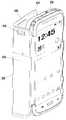
도 1은 카메라 폰의 외관을 전면 측에서 개략적으로 도시한 도면.
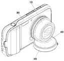
도 2는 카메라 폰의 외관을 배면 측에서 개략적으로 도시한 도면.
도 3은 카메라 폰의 외관을 상면 측에서 개략적으로 도시한 도면.
도 4는 본 개시의 실시 예에 따른 멀티기능을 구비한 전자기기의 보호 장치의 구조를 전면 측에서 도시한 도면.
도 5는 본 개시의 실시 예에 따른 멀티기능을 구비한 전자기기의 보호 장치의 구조를 측면에서 도시한 도면.
도 6은 본 개시의 실시 예에 따른 테두리 커버와 플립 커버의 결합 구조를 설명하기 위한 도면.
도 7은 테두리 커버와 플립 커버가 결합된 단면(A-A')을 도시하는 도면.
도 8은 본 개시의 실시 예에 따른 플립 커버가 전자기기를 커버했을 때 겉면을 도시한 도면.
도 9는 본 개시의 실시 예에 따른 플립 커버가 전자기기를 오픈했을 때 안쪽 면을 도시한 도면.
도 10은 본 개시의 실시 예에 따른 플립 커버에 구비되는 감지부를 설명하기 위한 도면.
도 11은 본 개시의 실시 예에 따른 렌즈 경통 커버를 지지대로 활용한 예를 도시한 도면.BRIEF DESCRIPTION OF THE DRAWINGS Fig. 1 is a view schematically showing the appearance of a camera phone from the front side; Fig.
2 is a view schematically showing the appearance of a camera phone from the back side;
3 is a view schematically showing an appearance of a camera phone on the upper surface side;
4 is a front view showing a structure of a protection device for an electronic device having multi functions according to an embodiment of the present disclosure;
Fig. 5 is a side view of the structure of a protective device for an electronic device having a multi-function according to the embodiment of the present disclosure; Fig.
6 is a view for explaining a coupling structure of a rim cover and a flip cover according to an embodiment of the present disclosure;
7 is a cross-sectional view (A-A ') in which a rim cover and a flip cover are combined.
Fig. 8 is a view showing a cover when the flip cover according to the embodiment of the present disclosure covers an electronic device; Fig.
9 is a view showing an inner surface of the flip cover according to the embodiment of the present disclosure when the electronic device is opened.
FIG. 10 is a view for explaining a sensing unit included in the flip cover according to the embodiment of the present disclosure; FIG.
11 is a view showing an example in which a lens barrel cover according to an embodiment of the present disclosure is used as a support.
이하, 첨부된 도면을 참조하여 본 개시의 다양한 실시 예들을 상세히 설명한다. 이때, 첨부된 도면에서 동일한 구성 요소는 가능한 동일한 부호로 나타내고 있음에 유의해야 한다. 또한, 본 개시의 요지를 흐리게 할 수 있는 공지 기능 및 구성에 대한 상세한 설명은 생략할 것이다.Various embodiments of the present disclosure will now be described in detail with reference to the accompanying drawings. Note that, in the drawings, the same components are denoted by the same reference numerals as possible. Further, the detailed description of well-known functions and constructions that may obscure the gist of the present disclosure will be omitted.
한편, 본 명세서와 도면에 개시된 다양한 실시 예들은 본 개시의 기술 내용을 쉽게 설명하고 본 개시의 이해를 돕기 위해 특정 예를 제시한 것일 뿐이며, 본 개시의 범위를 한정하고자 하는 것은 아니다. 여기에 개시된 실시 예들 이외에도 본 개시의 기술적 사상에 바탕을 둔 다른 변형 예들이 실시 가능하다는 것은 본 개시가 속하는 기술 분야에서 통상의 지식을 가진 자에게 자명한 것이다.It should be understood, however, that the various embodiments disclosed in this specification and drawings are provided by way of illustration only, and are not intended to limit the scope of the disclosure. It will be apparent to those skilled in the art that other modifications based on the technical idea of the present disclosure are possible in addition to the embodiments disclosed herein.
상세한 설명에 앞서, 본 개시의 실시 예에 따른 전자 기기는 이동통신 전자 기기, 스마트 폰(Smart Phone), 태블릿 PC(Personnel Computer), 개인 정보 전자 기기(Personal Digital Assistant : PDA) 등이 될 수 있다.Prior to detailed description, the electronic device according to the embodiment of the present disclosure may be a mobile communication electronic device, a smart phone, a personal computer (PC), a personal digital assistant (PDA), or the like .
본 개시에서 전자기기는 터치스크린과 렌즈 경통을 포함하고, 휴대폰, 스마트폰, 태블릿 PC, 노트북 PC 등과 같이 휴대 가능한 전자 기기를 의미한다. 본 개시에서 액세서리는 전자기기로부터 분리가 가능한 전자기기의 부속품으로써 예컨대, 터치스크린에 터치를 위한 펜, 헤드폰, 키패드, 렌즈 커버 등이 될 수 있다.In the present disclosure, an electronic device includes a touch screen and a lens barrel, and refers to a portable electronic device such as a mobile phone, a smart phone, a tablet PC, a notebook PC, and the like. An accessory in this disclosure may be an accessory of an electronic device that is detachable from an electronic device, such as a pen for touch on a touch screen, a headphone, a keypad, a lens cover, and the like.
이하에서 본 개시에 따른 멀티기능을 구비한 전자기기의 보호 장치에 대해 상세히 설명한다. 단, 본 개시를 설명함에 있어서, 관련된 공지 기능 또는 구성에 대한 구체적인 설명이 본 개시의 요지를 불필요하게 흐릴 수 있다고 판단되는 경우 그 상세한 설명은 생략한다. 또한 이하에서 사용되는 용어나 단어는 통상적이거나 사전적인 의미로 한정해서 해석되어서는 아니 되며, 본 개시의 기술적 사상에 부합하는 의미와 개념으로 해석되어야 한다. 따라서 아래 설명과 첨부된 도면은 본 개시의 바람직한 실시 예에 불과할 뿐이고, 본 발명의 기술적 사상을 모두 대변하는 것은 아니므로, 본 출원 시점에 있어서 이들을 대체할 수 있는 다양한 균등물과 변형 예들이 있을 수 있음을 이해하여야 한다. 또한, 첨부 도면에서 일부 구성요소는 과장되거나 생략되거나 또는 개략적으로 도시되었다.Hereinafter, a protective device for an electronic device having multi functions according to the present disclosure will be described in detail. In the following description of the present invention, however, the detailed description of known functions and configurations incorporated herein will be omitted when it may make the subject matter of the present disclosure rather unclear. Also, the terms or words used herein should not be construed as being limited to ordinary or dictionary meanings, and should be construed in a sense and concept consistent with the technical idea of the present disclosure. Therefore, the following description and the accompanying drawings are merely exemplary embodiments of the present invention and are not intended to represent all of the technical ideas of the present invention, so that various equivalents and modifications may be made thereto at the time of the present application . Moreover, some of the elements in the accompanying drawings are exaggerated, omitted, or schematically illustrated.
도 1은 카메라 폰의 외관을 전면 측에서 개략적으로 도시한 도면이고, 도 2는 카메라 폰의 외관을 배면 측에서 개략적으로 도시한 도면이며, 도 3은 카메라 폰의 외관을 상면 측에서 개략적으로 도시한 도면이다.Fig. 1 is a view schematically showing the appearance of a camera phone on the front side, Fig. 2 is a view schematically showing the outer appearance of the camera phone from the back side, Fig. 3 is an outline view of the camera phone, Fig.
도 1을 참조하면, 카메라 폰(100)은 전면(200)에 휴대 단말장치의 구성을 포함할 수 있다. 즉, 전면(200)에는 중앙에 표시부(205)를 포함할 수 있고, 표시부(205)의 상단에는 리시버(220), 조도 센서(235), 보조 카메라(230)가 위치하며, 표시부(205)의 하단에는 다수의 키가 위치할 수 있다. 예를 들어, 상기 다수의 키는 홈 키(210), 메뉴 키(212), 취소 키(214)를 포함할 수 있고, 버튼 방식의 물리적인 키 또는 터치 키로 형성될 수 있다. 표시부(250)는 기본적으로 애플리케이션 실행화면이나 홈 화면, 잠금 화면 등을 표시하고, 이를 제어하기 위해 사용자로부터 입력되는 이벤트를 감지하는 역할을 한다. 그리고 터치패널 및 표시패널을 포함하여 구성될 수 있다. 리시버(220)는 오디오 신호(예컨대, 통화음, MP3 재생음 등)의 출력 기능을 제공할 수 있다. 조도 센서(235)는 주변의 밝기를 감지하여 전자기기(100)가 화면의 밝기를 조절하도록 신호를 보낼 수 있다. 보조 카메라(230)는 화상 통화, 셀프 카메라 기능을 제공할 수 있다.Referring to FIG. 1, a
도 2를 참조하면, 카메라 폰(100)은 배면(110)에 카메라 장치의 구성을 포함할 수 있다. 즉, 배면(110)에는 렌즈 경통(120)을 포함하고, 스피커(150), 후레쉬(160) 및 AF 보조광(170)을 포함할 수 있다. 또한, 도시되지 않았으나, 카메라 폰(100)은 하면에 메모리 카드의 입출을 위한 메모리 카드 슬롯(Micro SD card slot)과 삼각대 연결을 위한 삼각대 연결 홈(Tripod Hole)을 더 포함할 수 있다.Referring to FIG. 2, the
렌즈 경통(120)은 렌즈 전면에 있는 피사체의 영상을 통과시키는 구성으로 적어도 하나의 렌즈를 포함하는 경통으로 구비될 수 있다. 통상적인 렌즈 경통은 하나 이상의 렌즈를 포함하여 피사체의 초점을 맞추거나, 광학 줌(optical zoom) 기능을 갖는다. 렌즈 경통(120)은 전자기기 배면(110)의 일부에 형성된 삽입부에 고정되거나, 탈착이 가능하도록 수용될 수 있다.
The
도 3을 참조하면, 카메라 폰(100)은 상면(130)에 휴대폰 기능에 연관된 소정의 버튼과, 카메라 기능에 연관된 소정의 버튼을 포함할 수 있다. 즉, 상면(130)에는 휴대폰 단말기 기능에 연관된 전원 버튼(140), 볼륨 버튼(142) 및 카메라 기능에 연관된 카메라 버튼(144)을 포함할 수 있다.
Referring to FIG. 3, the
도 4는 본 개시의 실시 예에 따른 멀티기능을 구비한 전자기기의 보호 장치의 구조를 전면 측에서 도시한 도면이고, 도 5는 본 개시의 실시 예에 따른 멀티기능을 구비한 전자기기의 보호 장치의 구조를 측면에서 도시한 도면이다.FIG. 4 is a front view showing the structure of a protection device for an electronic device having a multi-function according to the embodiment of the present disclosure, and FIG. 5 is a diagram showing the protection Figure 2 is a side view of the structure of the device.
도 4 및 도 5를 참조하면, 본 개시의 실시 예에 따른 멀티기능을 구비한 전자기기의 보호 장치는 테두리 커버(300), 플립 커버(600) 및 렌즈 경통(400)을 포함하여 구성될 수 있다.Referring to FIGS. 4 and 5, an apparatus for protecting a multi-function electronic apparatus according to an embodiment of the present disclosure may include a
테두리 커버(300)는 전자기기(100)의 테두리 면을 감싼다. 즉, 테두리 커버(300)는 전자기기(100)의 좌측면, 우측면, 상면 및 하면에 밀착하여 전자기기(100)를 외부 충격이나 스크래치로부터 보호할 수 있다. 테두리 커버(300)는 전자기기(100)를 끼울 때 전자장치(100)의 이어폰 잭 결합공, 외장 안테나 등은 외부로 노출되도록 다수의 홀을 포함할 수 있다. 또한, 렌즈 경통(400)을 보호 장치(300)에 탈착 가능하도록 수용하기 위한 방법으로 스트랩을 이용시, 상기 스트랩을 묶을 수 있는 홀을 포함할 수 있고, 테두리 커버(400)의 일측에 테두리 커버(400)를 전자기기(100)로부터 탈거하기 위한 손톱 홈(370)을 포함할 수 있다.The
특히, 본 개시의 실시 예에 따른 테두리 커버(300)는 서로 다른 재질의 두 케이스를 이중사출성형공정을 통해 단일구조로 제작할 수 있다. 여기서는 테두리 커버(300)를 제1 테두리 커버(320)와 제2 테두리 커버(340)가 결합된 구성으로 예시할 수 있으나, 이에 한정하지 않고 두 개 이상의 서로 다른 재질의 케이스가 결합된 구성도 수용할 수 있다.In particular, the
제1 테두리 커버(320)는 전자기기의 상면(130)에 구비된 전원 버튼(140), 볼륨 버튼(142) 및 카메라 버튼(144)을 커버하면서 그 상태에서도 눌림에 의한 압력을 버튼에 전달하기 위해 연질의 재료로 구성된다.The
예를 들어, 제1 테두리 커버(320)의 재질은 눌림에 의한 압력을 이에 밀착된 버튼에 전달하기 위하여 탄성을 갖고, 전자기기(100)의 표면과의 밀착력을 위해 표면 부착력이 우수하며, 전자기기(100)를 용이하게 장착하거나 탈착하기 위하여 신축성을 갖는 연성의 고무 재질로 구성되거나, 또는 합성수지재질로 구성될 수 있다. 합성수지재질로는 실리콘 재질, 폴리우레탄(TPU)과 같은 우레탄 재질을 사용할 수 있다.For example, the material of the
그리고 각 버튼에 입력되는 외부 압력이 실제 버튼에 더 잘 전달되게 하기 위해 각 버튼에 대면하는 제1 테두리 커버(320)의 내면은 도 6에 도시된 바와 같이 버튼에 대면하는 방향으로 소정만큼 돌출된 구조로 형성될 수 있다. 각 버튼에 대면하는 제1 테두리 커버(320)의 외면은 전자기기(100)의 표면으로부터 돌출된 각 버튼의 모양에 따라 외부 방향으로 돌출된 구조로 형성될 수 있다.The inner surface of the
제2 테두리 커버(340)는 테두리 커버(300)의 강성을 높이기 위해 제1 테두리 커버(320) 보다 단단하고 굳은 경질의 재료로 구성된다. 예를 들어, 제2 테두리 커버(340)는 에이 비 에스(ABS: Acrylonitrile Butadiene Styrene), 폴리아미드(PA), 폴리아세탈(POA), 폴리카보네이트(PC), 변성 폴리옥사이드(M-PRO), 폴리 부틸렌테레프 탈레이트(PBT), 폴리이미드(PI), 폴리페닐렌 설파이드(PPS), 폴리아미드이미드(PAI), 폴리에테르이미드(PEI), 폴리에테르케톤(PEK), 액정폴리 에스테르(LCP), 교대배열 폴리프로필렌(SPS), 실리콘, 고무, 금속, 무기물질 중 어느 하나 또는 이들의 합성 물질로 구비될 수 있다.The
테두리 커버(300)는 이와 같은 제1 테두리 커버(320)와 제2 테두리 커버(340)가 이중사출성형공정을 통해 결합된 구조로 구비될 수 있다.The
플립 커버(600)는 전자기기(100)의 미사용시 표시부(205)의 액정이 외부로 노출되지 않도록 전자기기의 전면(100)을 커버하거나, 사용시 표시부(205)가 노출되도록 오픈되는 형태로 구성될 수 있다.The
플립 커버(600)의 외부는 플립 커버(600) 전체를 둘러싸는 피복으로 구비될 수 있다. 상기 피복은 러버(rubber), 우레탄(Urethane), 실리콘(silicon), 가죽, 합성피혁, 섬유 중 적어도 하나일 수 있다. 플립 커버(600)의 피복은 벤딩 라인(620)을 제외한 나머지 부분에 해당하는 내부에 피복보다 단단하고 굳은 경질의 심을 포함할 수 있다.The outside of the
플립 커버(600)의 안쪽면, 즉 전자기기(100)의 액정 표시부(205)에 대면하는 부분은 액정 표시부(205)의 표면에 외부 마찰에 의한 스크래치의 발생을 방지하기 위해 부드러운 소재가 부착될 수 있다. 상기 부드러운 소재는 예를 들어, 샤무드, 인공 피혁, 스웨이드 원단, 마이크로 화이버(microfiber) 등과 같은 소재일 수 있다.The inner surface of the
한편, 플립 커버(600)를 이용하여 전자기기(100)의 실행을 제어하는 기능에 대해서는 이하에서 도 8 및 도 9를 참조하여 설명하기로 한다.
The function of controlling the execution of the
도 6은 본 개시의 실시 예에 따른 테두리 커버와 플립 커버의 결합 구조를 설명하기 위한 도면이고, 도 7은 테두리 커버와 플립 커버가 결합된 단면(A-A')을 도시하는 도면이다.Fig. 6 is a view for explaining a coupling structure of a rim cover and a flip cover according to an embodiment of the present disclosure, and Fig. 7 is a view showing a cross section A-A 'in which a rim cover and a flip cover are combined.
도 6 및 도 7을 참조하면, 플립 커버(600)는 테두리 커버의 일측부(670)에 결합되어, 전자기기(100)와 테두리 커버(300)의 경계 축을 기준으로 회전하여 전자기기 표시부(250)를 커버 또는 오픈하도록 구비된다.6 and 7, the
특히, 본 개시의 테두리 커버(300)와 플립 커버(600)는 상호 분리된 형태로 독립적으로 제작된 후, 일측부가 끼움 방식 및 초음파 융착 방식으로 상호 결합되어 제작될 수 있다.In particular, the
구체적으로, 테두리 커버(300)의 일부에 소정 깊이로 홈이 형성되고, 상기 홈에 플립 커버의 일부(670)가 수용된 후, 그 위에 락커(locker, 700) 부품이 적층된다. 이때, 테두리 커버(300)의 일부에 형성된 홈에 플립 커버의 일부(670) 및 락커(700)는 끼움 구조로 결합될 수 있다. 예컨대, 홈의 가장자리가 걸림턱 형태로 형성되고, 이에 플립커버의 일부(670) 및 락커(700)의 가장자리가 상기 걸림턱에 맞물리는 구조로 형성될 수 있다.Specifically, a groove is formed in a part of the
이와 같은 구조적 결합과 더불어, 초음파 융착 공정을 통해 테두리 커버(300), 플립 커버의 일부(670) 및 락커(700)를 더욱 견고히 결합시킬 수 있다.In addition to the structural coupling, the
초음파 융착이란 60Hz 전원의 전기적 에너지를 진동자를 통해 기계적 진동 에너지로 변환한 후 혼을 통해 가공물에 가압하면 접합면에 순간적으로 강력한 마찰열을 발생시켜 상기 접합면이 용해되어 서로 접착되는 가공 방법이다. 즉, 초음파 융착은 강한 분자적 결합을 발생시키는 공정방법이다. 강력한 분자 결합을 이용한 공정이므로 접착제의 이용을 생략할 수 있다.Ultrasonic welding is a processing method in which electrical energy of a 60 Hz power source is converted into mechanical vibration energy through a vibrator and then pressurized to a workpiece through a horn to generate strong frictional heat momentarily on the joint surface to dissolve and bond the joint surfaces. That is, ultrasonic welding is a process that generates strong molecular bonds. Since it is a process using strong molecular bonding, the use of an adhesive can be omitted.
이외에도 테두리 커버(300)와 플립 커버(600)는 상호 분리된 형태로 독립적으로 제작된 후, 일측부가 경첩 방식으로 상호 결합되거나 혹은 단일 사출성형공정을 통해 일체화된 단일 구조로 제작될 수도 있음에 한정하지 않는다.
In addition, the
다시 도 4 및 도 5를 참조하면, 본 개시의 실시 예에 따른 렌즈 경통 커버(400)는 렌즈 경통에 실장된 렌즈를 외부의 충격이나 마찰로부터 보호하기 위한 보호 케이스의 역할을 한다.Referring again to FIGS. 4 and 5, the
렌즈 경통 커버(400)의 둘레의 일부에는 스트링 커넥터(string connector, 460)가 돌출된 구조로 형성될 수 있다. 스트링 커넥터(460)에 스트랩(strap, 500)의 일단이 엮이고, 스트랩(500)의 타단이 테두리 커버(300)에 형성된 홀에 엮임으로써, 렌즈 경통 커버(400)가 보호 장치(300)에 추가로 구비될 수 있다. 이와 같은 구성에 의해 렌즈 경통 커버(400)는 보호 장치(300)로부터 탈착이 가능하다. 스트랩(500)은 신축성 재질 또는 비신축성 재질 중 어느 하나로 형성된 끈으로 구비될 수 있다.A
예를 들어, 렌즈 경통 커버(400)가 렌즈와 대면하는 부분은 투명 PC와 같은 재질로 구비될 수 있고, 렌즈 경통(120)과 밀착되는 렌즈 경통 커버(400)의 안쪽 둘레면(422)은 렌즈 경통(120)에 용이하게 장착되거나 탈착되기 위하여 신축성을 갖고, 렌즈 경통(120)의 표면과의 밀착력을 위해 표면 부착력이 우수한 연성의 고무 재질로 구성되거나, 또는 합성수지재질로 구성될 수 있다. 합성수지재질로는 실리콘 재질, 폴리우레탄(TPU)와 같은 우레탄 재질을 사용할 수 있다.For example, the portion where the
특히, 렌즈 경통 커버(400)는 도 11에 도시된 바와 같이 전자기기(100)를 평평한 지면에 세우기 위해 렌즈 경통 커버(400)를 지지대로 이용할 수 있다. 이를 위해, 렌즈 경통 커버(400)의 일부는 소정의 깊이로 패인 지지홈(450)을 포함할 수 있다. 지지홈(450)은 렌즈 경통(120)의 둘레 곡선을 따라 오목한 형태로 형성될 수 있다.
In particular, the
도 8은 본 개시의 실시 예에 따른 플립 커버가 전자기기를 커버했을 때 겉면을 도시한 도면이고, 도 9는 본 개시의 실시 예에 따른 플립 커버가 전자기기를 오픈했을 때 안쪽 면을 도시한 도면이며, 도 10은 본 개시의 실시예에 따른 플립 커버에 구비되는 감지부를 설명하기 위한 도면이다. Fig. 8 is a view showing a cover when the flip cover according to the embodiment of the present disclosure covers the electronic device, and Fig. 9 is a view showing the inside surface when the flip cover according to the embodiment of the present disclosure is opened And FIG. 10 is a view for explaining a sensing unit included in the flip cover according to the embodiment of the present disclosure.
도 8 및 도 9를 참조하면, 본 개시의 실시 예에 따른 플립 커버(600)는 플립 커버(600)를 벤딩(bending)할 수 있는 적어도 하나의 벤딩 라인(620)을 포함할 수 있다.8 and 9, a
벤딩 라인(620)은 피복으로 둘러싸인 플립 커버(600)의 내부에 경질의 심이 포함되지 않은 빈 공간으로 구성될 수 있다. 벤딩 라인(620)은 도 9에 도시된 바와 같이 소정의 각도로 벤딩될 수 있다. 플립 커버(600)를 이와 같은 구조로 구현함으로써, 플립 커버(600)를 전자장치(100)의 배면(110) 방향으로 젖혔을 때, 돌출된 렌즈 경통(120)에 의해 플립 커버(600)가 완전히 젖혀지지 못하는 상태를 보정할 수 있다.The
이를 위해 벤딩 라인(620)에 의해 분리된 플립 커버(600)의 일부 중 전자기기(100)에 가까운 쪽의 플립 커버(600) 일부의 가로 폭(L)은 전자장치(100)의 측면 두께와 렌즈 경통 커버(400)가 커버된 렌즈 경통(120)의 두께를 합친 길이에 대응하도록 형성될 수 있다.The lateral width L of a portion of the
이에 따라, 플립 커버(600)를 전자장치(100)의 배면(110) 방향으로 젖히면, 플립 커버(600)의 일부가 렌즈 경통(120)에 닿는 부위에서 벤딩 라인(620)에 의해 굽히면서 플립 커버(600)의 타부가 배면(110)의 표면과 평행하도록 젖혀질 수 있다. 이에 따라 사용자가 플립 커버(600)를 오픈한 상태에서 전자기기(100)를 손에 쥐었을 때 감기는 그립감에 지장을 미치지 않을 수 있다.
The
한편, 도면에 도시되지 않았으나, 본 개시의 실시 예에 따른 플립 커버(600)는 플립 커버(600)를 서로 다른 방향으로 굽힐 수 있는 복수의 벤딩 라인을 포함할 수 있다. 상기 벤딩 라인들을 각각 소정 각도로 굽혀 플립 커버(600)를 전자기기(100)의 지지대로 이용할 수 있다. 즉, 플립 커버(600)의 일부가 전자장치(100)의 배면(110)에 밀착된 상태에서 플립 커버(600)의 나머지 일부가 지면에 밀착되어 전자장치(100)의 무게를 지탱함으로써, 전자장치(100)가 스탠딩될 수 있다.
Meanwhile, although not shown in the drawings, the
플립 커버(600)는 감지부(640)를 내장하여 구성될 수 있다. 감지부(640)는 플립 커버(600)가 표시부(250)를 덮은 상태 또는 오픈한 상태를 검출하기 위해 구비될 수 있다. 감지부(640)는 자석 재질로 구비될 수 있고, 전자기기(100) 내부에 포함된 홀 센서(hall sensor)는 상기 자석 재질의 접근을 검출함으로써, 플립 커버(600)의 개폐 여부를 측정할 수 있다. 상기 홀 센서는 CPU(Central Processing Unit)나 AP(Application processor)와 같은 메인 프로세서가 전자기기(100)의 실행을 제어할 수 있도록 검출된 플립 커버(600)의 개폐 여부에 관한 정보를 전달한다.The
예를 들어, 상기 메인 프로세서는 플립 커버(600)가 표시부(250)를 덮은 상태라는 신호를 수신하면, 표시부(250) 화면을 슬립 모드로 전환할 수 있다. 반대로 플립 커버(600)가 표시부(250)를 오픈한 상태라는 신호를 수신하면, 사용자 입력이 발생하기 전까지 미리 정해진 소정 시간 동안 표시부(250) 화면을 활성화 모드로 운용할 수 있다.For example, when the main processor receives a signal indicating that the
이와 같은 홀 센서는 표시부(250) 바깥쪽의 전자기기(100) 상단에 위치할 수 있고, 자석 재질(640)은 도 8 및 도 9에 도시된 바와 같이 상기 홀 센서의 위치에 대면하는 플립 커버(600)의 상단에 위치할 수 있다. 이와 같이 자석 재질(640)과 홀 센서를 각각 전자기기(100)의 표시부(250)로부터 소정 간격 이격하여 상단에 배치함으로써, 자성에 의한 영향을 최소화할 수 있다. 자석 재질(640)은 플립 커버(600)의 외면을 구성하는 피복 내부에 구비되거나, 외면에 부착되어 구비될 수 있다.
Such a hall sensor may be located at the upper end of the
감지부(645)는 홀 센서를 통해 검출되는 자석 재질 이외에, 도 10에 도시된 바와 같이 센서 또는 특정 패턴으로 구비될 수 있다. 상기 센서 또는 특정 패턴은 플립 커버(600)가 표시부(250)로부터 이격되는 모션, 이격된 거리 및 이격된 각도 중 적어도 하나를 검출하기 위해 구비될 수 있다.The sensing unit 645 may be provided with a sensor or a specific pattern as shown in FIG. 10, in addition to the magnet material detected through the Hall sensor. The sensor or specific pattern may be provided to detect at least one of the motion, the spaced distance, and the spaced angle of the
감지부(645)가 센서로 구비되면, 상기 센서의 감지 결과를 전자기기(100) 내부의 메인 프로세서로 전달하기 위한 인터페이스부(미도시)가 전자기기(100)에 더 구비될 수 있다. 상기 인터페이스부는 센서와 메인 프로세서를 유선통신으로 연결하기 위한 구성으로 코드선, 접속잭 등으로 구비될 수 있다.When the sensing unit 645 is provided as a sensor, an interface unit (not shown) for transmitting the detection result of the sensor to the main processor in the
상기 센서는 비접촉식 센서 또는 접촉식 센서로 구성될 수 있다. 예를 들어, 접촉식 센서로는 마이크로 스위치, 리미트 스위치 중 적어도 하나가 이용될 수 있고, 비접촉식 센서로는 포토센서, 조도센서, 거리센서, 위치센서, 홀 센서, 모션센서, 근접센서, 자이로 센서, 가속도 센서 중 적어도 하나가 이용될 수 있다.The sensor may be a non-contact sensor or a touch sensor. For example, at least one of a micro switch and a limit switch may be used as the contact type sensor, and the non-contact type sensor may be a photosensor, an illuminance sensor, a distance sensor, a position sensor, a hall sensor, , And an acceleration sensor may be used.
이와 달리 감지부(645)가 특정 패턴ㅇ으로 구비될 수 있다. 특정 패턴(645)은 휴대 단말장치용 전용 터치펜이 표시부(250)의 하부에 장착된 이엠알 시트에 의해 검출되는 방법과 동일한 방법으로 검출될 수 있는 구성일 수 있다. 이엠알 시트(EMR sheet)는 터치펜이나 특정 패턴(645)의 근접을 감지하기 위해 표시부(250)를 구성하는 터치 패널에 포함되어 구비된다.Alternatively, the sensing unit 645 may be provided in a specific pattern. The specific pattern 645 may be a configuration that can be detected in the same manner as the method in which the dedicated touch pen for the portable terminal device is detected by the MML sheet mounted on the lower portion of the display unit 250. [ The EMR sheet is included in the touch panel that constitutes the display unit 250 to sense the proximity of the touch pen or the specific pattern 645.
전자장치에서 특정 패턴을 감지하는 동작을 설명하자면, 이엠알 시트의 PCB에 전류를 인가하여 공진(resonance)을 발생시킨 후, PCB 전류를 차단하고, 특정 패턴(645)의 공진에 의한 유도전류(induced current)를 측정한다. 그리고 메인 프로세서는 이엠알 시트를 스캔하여 입력되는 신호의 강도 차이로 특정 패턴(645)의 근접 또는 접촉 여부를 판단한다. 메인 프로세서는 특정 패턴(645)의 근접 또는 접촉 여부에 기초하여 플립 커버(600)의 개폐 여부를 판단하고, 이의 판단에 따라 전자기기 표시부(250) 화면의 온오프 또는 애플리케이션의 실행 모드를 제어할 수 있다.To describe a specific pattern sensing operation in an electronic device, a current is applied to the PCB of the MMS sheet to generate resonance, and then the PCB current is cut off and the induction current induced current. The main processor scans the MR sheet to determine whether the specific pattern 645 is in proximity or contact with the intensity difference of the input signal. The main processor determines whether the
예를 들어, 메인 프로세서는 특정 패턴(645)이 터치패널에 근접 또는 접촉된 것으로 검출되면, 플립 커버(600)가 표시부(250)를 덮은 상태로 판단하여, 표시부(250)의 화면을 슬립 모드로 전환하거나, 실행중이던 애플리케이션을 중지 또는 종료시킬 수 있다. 이와 반대로 특정 패턴(645)이 터치패널에 접촉하거나 근접하지 않은 것으로 검출되면, 플립 커버(600)가 표시부(250)를 오픈한 상태로 판단하여, 전자기기(100)의 슬립 모드였던 상태를 액티브 모드(active mode 또는 non-sleep mode)로 전환하거나, 실행이 중지된 애플리케이션을 다시 실행시킬 수 있다.
The main processor determines that the
이상에서 살펴본 바와 같이 본 개시의 다양한 실시 예들에 따른 멀티기능을 구비한 전자기기의 보호 장치는 테두리 커버와 플립 커버를 채용함으로써, 외부 충격에 의한 전자기기의 파손을 방지할 수 있다.As described above, according to various embodiments of the present disclosure, the protection device for an electronic device having a multi function can prevent breakage of the electronic device due to an external impact by adopting the frame cover and the flip cover.
또한, 본 개시는 서로 다른 재질로 구성된 보호 장치들 간에 물리적 결합 및 화학적 결합을 구현함으로써, 상호 분리된 형태로 독립적으로 제작된 보호 장치들을 서로 견고히 결합시키고, 이에 따라 보호 장치의 강성을 높일 수 있다.In addition, the present disclosure implements physical and chemical coupling between protective devices made of different materials, thereby firmly coupling the independently manufactured protective devices in mutually separated form to one another, thereby increasing the rigidity of the protective device .
더불어, 본 개시는 플립 커버에 감지부를 구비하고, 상기 감지부를 통해 플립 커버와 표시부 간의 상태를 검출함으로써, 상기 검출 상태에 따라 전자기기의 화면을 편리하고 신속하게 온오프 할 수 있다.In addition, the present disclosure has a sensing portion on a flip cover, and by detecting the state between the flip cover and the display portion through the sensing portion, the screen of the electronic device can be conveniently and quickly turned on and off according to the sensing state.
또한, 본 개시는 전자기기의 카메라 기능을 이용시, 렌즈 경통 커버에 형성된 지지 홈을 이용하여 카메라 폰을 안정적으로 지면에 지지할 수 있게 함으로써, 사용자 편의성을 높일 수 있다.Further, in the present disclosure, when using the camera function of the electronic device, the camera phone can be stably supported on the ground by using the support groove formed in the lens barrel cover, thereby improving the user's convenience.
이상에서는 본 개시의 다양한 실시 예에 따른 멀티 기능을 구비한 전자기기의 보호 장치에 대하여 본 명세서 및 도면을 통해 바람직한 실시 예들에 대하여 설명하였으며, 비록 특정 용어들이 사용되었으나 이는 단지 본 개시의 기술 내용을 쉽게 설명하고 개시의 이해를 돕기 위해 일반적인 의미에서 사용된 것일 뿐, 본 개시가 전술한 실시 예에 한정되는 것은 아니다. 즉, 본 개시의 기술적 사상에 바탕을 둔 다양한 실시 예가 가능함은 본 개시가 속하는 기술 분야에서 통상의 지식을 가진 자에게 자명한 것이다.While the present invention has been described in connection with what is presently considered to be the preferred embodiments, it is to be understood that the invention is not limited to the disclosed embodiments, but, on the contrary, It is to be understood that the present disclosure is not limited to the above-described embodiments. That is, it should be apparent to those skilled in the art that various embodiments based on the technical idea of the present disclosure are possible.
100: 카메라 폰120: 렌즈 경통
140: 전원 버튼142: 볼륨 버튼
144: 카메라 버튼150: 스피커
160: 후레쉬170: AF 보조광
205: 표시부300: 테두리 커버
400: 렌즈 경통 커버500: 스트랩
600: 플립 커버700: 락커100: camera phone 120: lens barrel
140: Power button 142: Volume button
144: camera button 150: speaker
160: Flash 170: AF illuminator
205: Display part 300: Rim cover
400: lens barrel cover 500: strap
600: Flip cover 700: Locker
Claims (16)
Translated fromKorean전자기기의 테두리 면을 감싸는 테두리 커버;
상기 테두리 커버의 일측부에 결합되어, 상기 전자기기와의 경계 축을 기준으로 회전하여 상기 전자기기 전면의 표시부를 커버 또는 오픈하도록 구비된 플립 커버; 및
상기 테두리 커버에 탈착 가능하고, 상기 전자기기 배면에 구비된 렌즈 경통의 일부 형상에 대응하는 형태로 구비된 렌즈 경통 커버를 포함하는, 멀티기능을 구비한 전자기기의 보호 장치.A protection device for an electronic device having a multi-function,
A frame cover surrounding the edge of the electronic device;
A flip cover coupled to one side of the rim cover, the flip cover being rotatable about a boundary axis with the electronic device and covering or opening a display portion of the front surface of the electronic device; And
And a lens barrel cover detachably attached to the frame cover and provided in a shape corresponding to a shape of a lens barrel provided on a back surface of the electronic device.
상기 테두리 커버는 가장자리 일부에 소정 깊이로 형성된 홈을 포함하고, 상기 홈에 상기 플립 커버의 일부와 락커(locker)가 적층되어 끼움 체결됨으로써, 상기 플립 커버와 물리적으로 체결된 구조인, 멀티기능을 구비한 전자기기의 보호 장치.The method according to claim 1,
The frame cover includes a groove formed at a predetermined depth in a part of an edge of the flip cover, and a part of the flip cover and a locker are laminated and fitted into the groove so that the flip cover is physically fastened to the flip cover. (1).
상기 테두리 커버의 가장자리 일부에 형성된 홈은 걸림턱을 포함하고, 상기 플립 커버의 일부와 상기 락커는 상기 걸림턱에 맞물리는 구조로 형성된, 멀티기능을 구비한 전자기기의 보호 장치.3. The method of claim 2,
Wherein a groove formed in a part of an edge of the rim cover includes a latching jaw and a part of the flip cover and the locker are engaged with the latching jaw.
상기 홈 위에 상기 플립 커버의 일부와 상기 락커(locker)가 적층된 상태에서 초음파 융착에 의해 상기 홈, 플립 커버의 일부 및 상기 락커 간의 접합면이 분자적 결합된, 멀티기능을 구비한 전자기기의 보호 장치.3. The method of claim 2,
Wherein the groove, the part of the flip cover and the contact surface between the locker are molecularly bonded by ultrasonic welding in a state where a part of the flip cover and the locker are laminated on the groove, Protection device.
연질성 재질의 제1 테두리 커버와 경질성 재질의 제2 테두리 커버가 결합된 구성인, 멀티기능을 구비한 전자기기의 보호 장치.[2] The apparatus according to claim 1,
A protective device for a multi-function electronic device, comprising a first rim cover made of soft material and a second rim cover made of hard material.
상기 제1 테두리 커버는 상기 전자기기의 일측면에 구비된 복수의 버튼에 대면하는 위치에 구비되어, 외부로부터 눌림에 의한 압력을 상기 버튼에 전달하는 구조인, 멀티기능을 구비한 전자기기의 보호 장치.6. The method of claim 5,
Wherein the first rim cover is provided at a position facing a plurality of buttons provided on one side surface of the electronic device and transmits a pressure due to the pressing from the outside to the button, Device.
상기 플립 커버의 일부가 접힘이 가능한 적어도 하나의 벤딩 라인을 포함하는, 멀티기능을 구비한 전자기기의 보호 장치.The flip cover according to claim 1,
Wherein the flip cover includes at least one bending line capable of folding a part of the flip cover.
상기 벤딩 라인에 의해 분리된 상기 플립 커버 일부의 가로 폭은 상기 전자장치의 측면 두께와 상기 렌즈 경통 커버가 상기 렌즈 경통에 커버된 두께를 합친 길이에 대응하는, 멀티기능을 구비한 전자기기의 보호 장치.8. The method of claim 7,
Wherein a width of the flip cover part separated by the bending line corresponds to a length of the side wall thickness of the electronic device and the thickness of the lens barrel cover combined with the thickness of the lens barrel, Device.
외면이 피복으로 구성되고, 상기 피복 내부에 상기 피복보다 단단하고 굳은 경질의 심으로 구성되고, 상기 벤딩 라인은 상기 피복 내부에 상기 심이 생략된 빈 공간으로 구성된, 멀티기능을 구비한 전자기기의 보호 장치.8. The flip cover as claimed in claim 7,
Wherein the outer surface is made of a covering and the inside of the covering is made of a hard core harder and harder than the covering, and the bending line is a space for protecting the multifunctional electronic device Device.
상기 전자기기의 배면 방향으로 젖힐 경우, 상기 렌즈 경통에 닿는 부위에서 상기 벤딩 라인에 의해 접히는 구조인, 멀티기능을 구비한 전자기기의 보호 장치.8. The flip cover as claimed in claim 7,
Wherein the lens barrel is folded by the bending line at a position in contact with the lens barrel when the lens barrel is tilted toward the back of the electronic device.
상기 표시부로부터 상기 플립 커버가 이격되는 모션, 이격된 거리, 이격된 각도 중 적어도 하나를 검출하기 위한 감지부를 구비하는, 멀티기능을 구비한 전자기기의 보호 장치.The flip cover according to claim 1,
And a sensing unit for sensing at least one of a motion in which the flip cover is spaced from the display unit, a spaced distance, and a spaced angle.
상기 플립 커버와 상기 표시부 간의 상태를 검출하여, 상기 검출 결과를 상기 전자기기의 메인 프로세서에 전달하고, 상기 메인 프로세서는 상기 검출 결과에 따라 상기 전자기기의 실행을 제어하는, 멀티기능을 구비한 전자기기의 보호 장치.The apparatus of claim 1,
A main processor for detecting the state between the flip cover and the display unit and delivering the detection result to the main processor of the electronic equipment, and the main processor controlling the execution of the electronic equipment in accordance with the detection result, Protection device of the device.
둘레면 일부에 스트링 커넥터를 포함하고, 상기 스트링 커넥터와 상기 테두리 커버에 형성된 홀에 일단과 타단이 엮인 스트랩에 의해 상기 테두리 커버에 체결된, 멀티기능을 구비한 전자기기의 보호 장치.The lens barrel according to claim 1,
And a string connector including a string connector on a part of the circumferential surface and being fastened to the frame cover by a strap having one end and another end woven in a hole formed in the string connector and the frame cover.
렌즈와 대면하는 부분은 투명 PC로 구비되고, 상기 렌즈 경통과 밀착하는 안쪽 둘레면은 탄성 재질로 구비되는, 멀티기능을 구비한 전자기기의 보호 장치.The lens barrel according to claim 1,
Wherein a portion facing the lens is made of a transparent PC, and an inner circumferential surface in close contact with the lens barrel is made of an elastic material.
상기 전자기기를 지면에 세우기 위해 표면의 일부에 구비된 지지홈을 포함하는, 멀티기능을 구비한 전자기기의 보호 장치.The lens barrel according to claim 1,
And a support groove provided on a part of the surface for erecting the electronic device on the ground.
상기 렌즈 경통의 둘레를 따라 오목한 형태로 형성된, 멀티기능을 구비한 전자기기의 보호 장치.16. The apparatus according to claim 15,
Wherein the lens barrel is formed in a concave shape along the periphery of the lens barrel.
Priority Applications (3)
| Application Number | Priority Date | Filing Date | Title |
|---|---|---|---|
| KR1020130071126AKR102086718B1 (en) | 2013-06-20 | 2013-06-20 | Protective device having multi function for electronic device |
| US14/301,574US9426911B2 (en) | 2013-06-20 | 2014-06-11 | Protective apparatus for electronic device |
| EP14173123.2AEP2816443B1 (en) | 2013-06-20 | 2014-06-19 | Protective apparatus for electronic device |
Applications Claiming Priority (1)
| Application Number | Priority Date | Filing Date | Title |
|---|---|---|---|
| KR1020130071126AKR102086718B1 (en) | 2013-06-20 | 2013-06-20 | Protective device having multi function for electronic device |
Publications (2)
| Publication Number | Publication Date |
|---|---|
| KR20140147577Atrue KR20140147577A (en) | 2014-12-30 |
| KR102086718B1 KR102086718B1 (en) | 2020-03-09 |
Family
ID=51257247
Family Applications (1)
| Application Number | Title | Priority Date | Filing Date |
|---|---|---|---|
| KR1020130071126AExpired - Fee RelatedKR102086718B1 (en) | 2013-06-20 | 2013-06-20 | Protective device having multi function for electronic device |
Country Status (3)
| Country | Link |
|---|---|
| US (1) | US9426911B2 (en) |
| EP (1) | EP2816443B1 (en) |
| KR (1) | KR102086718B1 (en) |
Families Citing this family (3)
| Publication number | Priority date | Publication date | Assignee | Title |
|---|---|---|---|---|
| KR102305462B1 (en)* | 2015-04-30 | 2021-09-27 | 삼성디스플레이 주식회사 | Flexible window substrate and flexible display device having the same |
| CN107637059B (en) | 2016-04-29 | 2021-07-27 | 深圳市大疆灵眸科技有限公司 | Shooting device, shooting equipment and portable electronic equipment |
| CN106973524A (en)* | 2017-04-20 | 2017-07-21 | 高德(无锡)电子有限公司 | A kind of uncovering method of Rigid Flex |
Citations (2)
| Publication number | Priority date | Publication date | Assignee | Title |
|---|---|---|---|---|
| JPH0583735U (en)* | 1992-04-13 | 1993-11-12 | 船井電機株式会社 | Lens cap |
| KR20130018393A (en)* | 2011-08-13 | 2013-02-21 | 김덕승 | Protect case for portable device and method for control on/off of screen |
Family Cites Families (16)
| Publication number | Priority date | Publication date | Assignee | Title |
|---|---|---|---|---|
| US7735644B2 (en)* | 2007-06-06 | 2010-06-15 | Belkin International, Inc. | Case for electrical device and method of using same |
| JP2010128162A (en) | 2008-11-27 | 2010-06-10 | Fujifilm Corp | Water-proof camera, water-proof case, and digital camera |
| US8672126B2 (en) | 2010-01-06 | 2014-03-18 | Apple Inc. | Foldable case for use with an electronic device |
| US8390411B2 (en)* | 2010-09-17 | 2013-03-05 | Apple Inc. | Tablet device |
| KR101793313B1 (en)* | 2010-10-12 | 2017-11-02 | 트리프로그 디벨롭먼츠, 인크. | Housing for encasing an electronic device |
| KR101701157B1 (en) | 2010-11-08 | 2017-02-02 | 삼성전자주식회사 | Cover device of a folder type terminal |
| WO2012149206A2 (en)* | 2011-04-29 | 2012-11-01 | xDEV, INC. | Protective cover for an electronic device |
| JP3170512U (en)* | 2011-06-03 | 2011-09-22 | 株式会社パワーサポート | Back protection cover for tablet devices |
| CN103034382B (en)* | 2011-10-03 | 2016-03-02 | 朱敏芳 | Waterproof housing for digital device with capacitive touch screen and its actuating mechanism |
| US8770402B2 (en)* | 2012-01-26 | 2014-07-08 | Iceberg Commerce Inc. | Waterproof protective case for a mobile device |
| US8967377B2 (en)* | 2012-02-07 | 2015-03-03 | Ian F Lebauer | Protective case for portable electronic device with foldable lens cover and storage compartments |
| US20130258586A1 (en)* | 2012-04-02 | 2013-10-03 | Aevoe International Ltd. | Protective apparatus for tablet electronic device |
| TWM443370U (en)* | 2012-06-04 | 2012-12-11 | fu-yi Xu | Protective cover |
| KR102009744B1 (en)* | 2013-01-03 | 2019-10-21 | 삼성전자주식회사 | Portable electronic apparatus and cover device for thereof |
| KR102058369B1 (en)* | 2013-01-29 | 2019-12-24 | 엘지전자 주식회사 | Mobile terminal and cover for the same |
| KR102047882B1 (en)* | 2013-04-02 | 2019-11-22 | 삼성전자주식회사 | Electronic device having cover |
- 2013
- 2013-06-20KRKR1020130071126Apatent/KR102086718B1/ennot_activeExpired - Fee Related
- 2014
- 2014-06-11USUS14/301,574patent/US9426911B2/ennot_activeExpired - Fee Related
- 2014-06-19EPEP14173123.2Apatent/EP2816443B1/enactiveActive
Patent Citations (2)
| Publication number | Priority date | Publication date | Assignee | Title |
|---|---|---|---|---|
| JPH0583735U (en)* | 1992-04-13 | 1993-11-12 | 船井電機株式会社 | Lens cap |
| KR20130018393A (en)* | 2011-08-13 | 2013-02-21 | 김덕승 | Protect case for portable device and method for control on/off of screen |
Also Published As
| Publication number | Publication date |
|---|---|
| EP2816443B1 (en) | 2020-02-19 |
| EP2816443A2 (en) | 2014-12-24 |
| US20140374309A1 (en) | 2014-12-25 |
| KR102086718B1 (en) | 2020-03-09 |
| EP2816443A3 (en) | 2015-04-29 |
| US9426911B2 (en) | 2016-08-23 |
Similar Documents
| Publication | Publication Date | Title |
|---|---|---|
| KR101474418B1 (en) | Pouch and portable terminal having th e same | |
| KR102391961B1 (en) | Electronic device including flexible display | |
| CN204425433U (en) | Mobile terminal | |
| US9559740B2 (en) | Mobile terminal case and mobile terminal | |
| US9013863B2 (en) | Protective sheath | |
| US9729688B2 (en) | Mobile terminal | |
| KR102207039B1 (en) | Protecting cover | |
| US9609099B2 (en) | Mobile terminal | |
| US9918395B1 (en) | Three part foldable housing supporting multiple use positions in an electronic device | |
| US10613589B2 (en) | Electronic device | |
| US10558833B2 (en) | Key module and mobile terminal having the same | |
| JP6275943B2 (en) | Portable electronic devices | |
| KR20160098871A (en) | Waterproof case and mobile terminal using the same | |
| KR20210099974A (en) | Electronic device include sound path | |
| US10659577B2 (en) | Hinge for a foldable-type mobile device | |
| KR101695382B1 (en) | Case Having Mouse Function | |
| KR102086718B1 (en) | Protective device having multi function for electronic device | |
| US9894191B2 (en) | Mobile terminal | |
| US9977528B2 (en) | Electronic device having touch sensor | |
| KR101307635B1 (en) | Protective cover for portable communication device | |
| KR101969899B1 (en) | Mobile terminal | |
| KR102113269B1 (en) | Electronic device with protective case and operating method thereof | |
| JP2010130244A (en) | Mobile electronic equipment | |
| KR20160109114A (en) | Charging connection apparatus having lighting function | |
| KR20210145395A (en) | Electronic device including pressure sensor module |
Legal Events
| Date | Code | Title | Description |
|---|---|---|---|
| PA0109 | Patent application | St.27 status event code:A-0-1-A10-A12-nap-PA0109 | |
| PG1501 | Laying open of application | St.27 status event code:A-1-1-Q10-Q12-nap-PG1501 | |
| PA0201 | Request for examination | St.27 status event code:A-1-2-D10-D11-exm-PA0201 | |
| D13-X000 | Search requested | St.27 status event code:A-1-2-D10-D13-srh-X000 | |
| D14-X000 | Search report completed | St.27 status event code:A-1-2-D10-D14-srh-X000 | |
| E902 | Notification of reason for refusal | ||
| PE0902 | Notice of grounds for rejection | St.27 status event code:A-1-2-D10-D21-exm-PE0902 | |
| E13-X000 | Pre-grant limitation requested | St.27 status event code:A-2-3-E10-E13-lim-X000 | |
| P11-X000 | Amendment of application requested | St.27 status event code:A-2-2-P10-P11-nap-X000 | |
| P13-X000 | Application amended | St.27 status event code:A-2-2-P10-P13-nap-X000 | |
| E701 | Decision to grant or registration of patent right | ||
| PE0701 | Decision of registration | St.27 status event code:A-1-2-D10-D22-exm-PE0701 | |
| GRNT | Written decision to grant | ||
| PR0701 | Registration of establishment | St.27 status event code:A-2-4-F10-F11-exm-PR0701 | |
| PR1002 | Payment of registration fee | St.27 status event code:A-2-2-U10-U11-oth-PR1002 Fee payment year number:1 | |
| PG1601 | Publication of registration | St.27 status event code:A-4-4-Q10-Q13-nap-PG1601 | |
| PC1903 | Unpaid annual fee | St.27 status event code:A-4-4-U10-U13-oth-PC1903 Not in force date:20230304 Payment event data comment text:Termination Category : DEFAULT_OF_REGISTRATION_FEE | |
| PC1903 | Unpaid annual fee | St.27 status event code:N-4-6-H10-H13-oth-PC1903 Ip right cessation event data comment text:Termination Category : DEFAULT_OF_REGISTRATION_FEE Not in force date:20230304 |