KR20140135633A - Lockable syringe and method of assembling same - Google Patents
Lockable syringe and method of assembling sameDownload PDFInfo
- Publication number
- KR20140135633A KR20140135633AKR1020140056957AKR20140056957AKR20140135633AKR 20140135633 AKR20140135633 AKR 20140135633AKR 1020140056957 AKR1020140056957 AKR 1020140056957AKR 20140056957 AKR20140056957 AKR 20140056957AKR 20140135633 AKR20140135633 AKR 20140135633A
- Authority
- KR
- South Korea
- Prior art keywords
- plunger
- threaded
- syringe body
- internal threaded
- threaded member
- Prior art date
- Legal status (The legal status is an assumption and is not a legal conclusion. Google has not performed a legal analysis and makes no representation as to the accuracy of the status listed.)
- Granted
Links
- 238000000034methodMethods0.000titleclaimsdescription21
- 230000007246mechanismEffects0.000claimsabstractdescription12
- 239000012530fluidSubstances0.000claimsabstractdescription11
- 230000008878couplingEffects0.000claimsdescription4
- 238000010168coupling processMethods0.000claimsdescription4
- 238000005859coupling reactionMethods0.000claimsdescription4
- 238000004891communicationMethods0.000claimsdescription3
- 230000001225therapeutic effectEffects0.000abstractdescription3
- 238000003825pressingMethods0.000abstractdescription2
- 230000008901benefitEffects0.000description7
- 238000000926separation methodMethods0.000description3
- 230000008859changeEffects0.000description2
- 238000013461designMethods0.000description2
- 238000009434installationMethods0.000description2
- 230000001681protective effectEffects0.000description2
- 238000007789sealingMethods0.000description2
- 238000013459approachMethods0.000description1
- 230000005540biological transmissionEffects0.000description1
- 238000010276constructionMethods0.000description1
- 238000006073displacement reactionMethods0.000description1
- 230000000694effectsEffects0.000description1
- 230000003993interactionEffects0.000description1
- 238000005304joiningMethods0.000description1
- 230000014759maintenance of locationEffects0.000description1
- 238000012986modificationMethods0.000description1
- 230000004048modificationEffects0.000description1
- 238000002360preparation methodMethods0.000description1
- 238000010926purgeMethods0.000description1
- 230000000717retained effectEffects0.000description1
Images


Classifications
- A—HUMAN NECESSITIES
- A61—MEDICAL OR VETERINARY SCIENCE; HYGIENE
- A61M—DEVICES FOR INTRODUCING MEDIA INTO, OR ONTO, THE BODY; DEVICES FOR TRANSDUCING BODY MEDIA OR FOR TAKING MEDIA FROM THE BODY; DEVICES FOR PRODUCING OR ENDING SLEEP OR STUPOR
- A61M5/00—Devices for bringing media into the body in a subcutaneous, intra-vascular or intramuscular way; Accessories therefor, e.g. filling or cleaning devices, arm-rests
- A61M5/48—Devices for bringing media into the body in a subcutaneous, intra-vascular or intramuscular way; Accessories therefor, e.g. filling or cleaning devices, arm-rests having means for varying, regulating, indicating or limiting injection pressure
- A61M5/484—Regulating injection pressure
- A—HUMAN NECESSITIES
- A61—MEDICAL OR VETERINARY SCIENCE; HYGIENE
- A61M—DEVICES FOR INTRODUCING MEDIA INTO, OR ONTO, THE BODY; DEVICES FOR TRANSDUCING BODY MEDIA OR FOR TAKING MEDIA FROM THE BODY; DEVICES FOR PRODUCING OR ENDING SLEEP OR STUPOR
- A61M25/00—Catheters; Hollow probes
- A61M25/10—Balloon catheters
- A61M25/1018—Balloon inflating or inflation-control devices
- A61M25/10181—Means for forcing inflation fluid into the balloon
- A61M25/10182—Injector syringes
- A—HUMAN NECESSITIES
- A61—MEDICAL OR VETERINARY SCIENCE; HYGIENE
- A61M—DEVICES FOR INTRODUCING MEDIA INTO, OR ONTO, THE BODY; DEVICES FOR TRANSDUCING BODY MEDIA OR FOR TAKING MEDIA FROM THE BODY; DEVICES FOR PRODUCING OR ENDING SLEEP OR STUPOR
- A61M25/00—Catheters; Hollow probes
- A61M25/10—Balloon catheters
- A61M25/1018—Balloon inflating or inflation-control devices
- Y—GENERAL TAGGING OF NEW TECHNOLOGICAL DEVELOPMENTS; GENERAL TAGGING OF CROSS-SECTIONAL TECHNOLOGIES SPANNING OVER SEVERAL SECTIONS OF THE IPC; TECHNICAL SUBJECTS COVERED BY FORMER USPC CROSS-REFERENCE ART COLLECTIONS [XRACs] AND DIGESTS
- Y10—TECHNICAL SUBJECTS COVERED BY FORMER USPC
- Y10T—TECHNICAL SUBJECTS COVERED BY FORMER US CLASSIFICATION
- Y10T29/00—Metal working
- Y10T29/49—Method of mechanical manufacture
- Y10T29/49826—Assembling or joining
- Y10T29/49881—Assembling or joining of separate helix [e.g., screw thread]
Landscapes
- Health & Medical Sciences (AREA)
- Life Sciences & Earth Sciences (AREA)
- Heart & Thoracic Surgery (AREA)
- Public Health (AREA)
- Animal Behavior & Ethology (AREA)
- Veterinary Medicine (AREA)
- Engineering & Computer Science (AREA)
- Anesthesiology (AREA)
- Biomedical Technology (AREA)
- Hematology (AREA)
- General Health & Medical Sciences (AREA)
- Biophysics (AREA)
- Child & Adolescent Psychology (AREA)
- Pulmonology (AREA)
- Vascular Medicine (AREA)
- Infusion, Injection, And Reservoir Apparatuses (AREA)
- Media Introduction/Drainage Providing Device (AREA)
Abstract
Translated fromKorean
Description
Translated fromKorean본원은 2013년 5월 16일자로 출원된 미국 가특허출원 제 61/824,243 호의 이익 향유를 주장하고, 상기 출원 전체가 본원에서 참조로서 포함된다.The present application claims benefit benefit of U.S. Provisional Patent Application No. 61 / 824,243, filed May 16, 2013, the entirety of which is incorporated herein by reference.
본원은 일반적으로, 풍선 카테터(balloon catheter)와 같은, 의료용 장치를 가압하기 위한 록킹가능한 주사기에 관한 것이고, 또한 록킹가능한 주사기를 조립하기 위한 방법에 관한 것이다.The present disclosure relates generally to a lockable syringe for pressurizing a medical device, such as a balloon catheter, and also to a method for assembling a lockable syringe.
풍선(balloon) 카테터의 팽창 중에, 의료 제공자가 풍선으로 제공되는 압력을 용이하고 정밀하게 제어할 수 있는 것이 요구될 수 있을 것이다. 풍선에 대해 또는 풍선으로부터 상당량의 압력을 신속하게 인가하거나 제거할 수 있는 것이 요구될 수 있는 한편, 풍선에 대해서 단지 적은 추가적인 압력을 부가하거나 단지 적은 압력을 제거할 수 있는 것이 또한 요구될 수 있다.During inflation of the balloon catheter, it may be desirable for the medical provider to be able to easily and precisely control the pressure provided by the balloon. It may also be desirable to be able to apply or remove a significant amount of pressure to or from the balloon quickly, while it may also be required to add only a small additional pressure or only a small pressure to the balloon.
록킹가능한 주사기(예를 들어, 미국 특허 제 5,057,078 호 및 제 6,938,319 호에 개시된 장치 참조)가, 풍선 카테터로 인가되는 압력을 정밀하게 제어하기 위한 의료 분야에서 일반화되었다. 전형적인 록킹가능한 주사기는, 하나의 상태에서, 플런저의 핸들을 단순히 잡아 당기는 것에 의해서, 플런저가 배럴(barrel) 내로 신속하게 이동될 수 있는 것을 제공한다. 이는, 풍선 카테터에 대한 압력의 신속한 변화를 유발한다. 다른 한편으로, 주사기가 록킹된 위치에 배치될 수 있고, 그에 의해서 주사기가 다른 상태가 되게 할 수 있다. 이러한 다른 상태에서, 플런저의 핸들이 푸싱되거나(pushed) 잡아 당겨지지 않을 수 있다. 그 대신에, 핸들이 반드시 회전되어야 하고, 그에 의해서 플런저가 배럴 내로 서서히 진행하거나 또는 배럴로부터 후퇴될 수 있게 유도한다. 따라서, 록킹가능한 주사기는 2개의 상태의 효과적인 동작을 제공하고, 상기 2개의 상태는 - 거시적 이동을 위한 제 1 상태로서, 그러한 제 1 상태 중에 풍선 카테터 압력이 비교적 신속하게 크게 변화될 수 있는, 제 1 상태, 그리고 미시적 이동을 위한 제 2 상태로서, 상기 제 2 상태 중에 풍선 카테터 압력이 보다 정밀하게 그리고 서서히 제어될 수 있는, 제 2 상태이다.Lockable syringes (see, for example, the devices disclosed in U. S. Patent Nos. 5,057, 078 and 6,938, 319) have been generalized in the medical field for precisely controlling the pressure applied to a balloon catheter. A typical lockable syringe provides that, in one state, the plunger can be quickly moved into the barrel by simply pulling the plunger handle. This causes a rapid change in pressure to the balloon catheter. On the other hand, the syringe may be placed in the locked position, thereby causing the syringe to assume a different state. In this other state, the handle of the plunger may not be pushed or pulled. Instead, the handle must be rotated, thereby causing the plunger to progress slowly into or out of the barrel. Thus, a lockable syringe provides effective operation of two states, the two states being: a first state for macroscopic movement, during which the balloon catheter pressure can be changed relatively rapidly, 1 state, and a second state for microscopic movement, during which the balloon catheter pressure can be more precisely and slowly controlled.
록킹가능한 주사기가 몇 가지 장점을 제공하지만, 풍선 카테터 시술에서 현재 이용할 수 있는 많은 록킹가능한 주사기는 사용하기가 어렵고, 조립이 어렵고, 및/또는 너무 많은 부품을 포함한다.Although lockable syringes offer several advantages, many lockable syringes currently available in balloon catheterization procedures are difficult to use, difficult to assemble, and / or include too many components.
본원 발명의 실시예의 목적은 사용이 용이하고, 조립이 용이하고, 그리고 너무 많은 부품을 포함하지 않는 록킹가능한 주사기를 제공하는 것이다.It is an object of embodiments of the present invention to provide a lockable syringe that is easy to use, easy to assemble, and does not include too many components.
간략히 설명하면, 본원 발명의 실시예는 이동가능한 나사산 베어링 플런저 부재를 신속하게 그리고 선택적으로 배치하기 위한 작동 메커니즘, 및 특히 주사기를 이용하여 치료적인 의료용 풍선 카테터를 가압하는 것 등을 위해서, 나사 결합되고(threaded) 또는 나사 결합으로부터 벗어나는 정지형(stationary) 내부 나사산형 실린더를 가지는 록킹가능한 주사기를 제공한다. 상기 메커니즘은 단일형(unitary) 주사기 본체의 배럴 부분과 결합하기 위한 피스톤을 단부에 가지는 플런저, 선택적으로 전개가능하고 후퇴가능한 나사산형 세그먼트, 및 배럴을 가지는 단일형 주사기 본체 내에 배치된 내부 나사산형 원통형 구조물을 포함한다. 상기 플런저는 나사산형 세그먼트에 의해서 상기 나사산형 실린더, 및 조작자 작동형 데스모드로믹 배열체(desmodromic arrangement)와 결합될 수 있고, 그에 따라 내부에 수용된 작업 유체를 변위 또는 가압하기 위한 목적을 위해서, 주사기의 배럴 내의 신속한 수작업 또는 나사산 제어형 플런저 및 피스톤 이동을 허용하기 위한 확실한(positive) 방식으로 나사산형 세그먼트를 제어가능하게 왕복시킨다.Briefly, an embodiment of the present invention provides an actuation mechanism for quickly and selectively disposing a movable threaded bearing plunger member, and, in particular, for screwing a therapeutic medical balloon catheter using a syringe the present invention provides a lockable syringe having a stationary internal threaded cylinder that is threaded or deviates from a threaded engagement. The mechanism includes an internally threaded cylindrical structure disposed within a single syringe body having a plunger at its end for engaging a barrel portion of a unitary syringe body, a selectively deployable and retractable threaded segment, and a barrel . The plunger may be combined with the threaded cylinder by means of threaded segments and with an operator-operated desmodmodromic arrangement, and for the purpose of displacing or compressing the working fluid contained therein, Controllably reciprocates threaded segments in a positive manner to allow rapid manual or threaded controlled plunger and piston movement within the barrel of the syringe.
플런저 내로 나사산형 세그먼트를 방사상 삽입하는 것을 제외하고, 록킹가능한 주사기의 모든 메커니즘 구성요소는, 바람직하게 스냅(snap) 구성 수단에 의해서 함께 제 위치에서 유지되도록, 단일형 주사기 본체의 개방된 후방부 내로의 신속한 순차적인 축방향 조립을 제공하도록 구성된다. 바람직하게 단일형 주사기 본체의 배럴 내의 작업 유체의 관찰을 허용하기 위해서 그리고 사용을 위한 준비 중에 충진 및 포획된 공기의 퍼지 모두를 촉진하기 위해서 전체적으로 투명한 단일형 주사기 본체는, 바람직하게 상기 배럴에 의해서 수용되는 작업 유체와 직접적으로 소통하는 동작을 위한 압력 게이지 메커니즘을 수용하기 위한 내부 게이지 하우징을 제공하도록 구성된다. 이러한 하우징의 배럴 단부는 또한 바람직하게, 유체 전달 호스를 수용하고 본딩하기 위한 소켓으로 구성되고, 상기 호스는 바람직하게 의료용 풍선 카테터 및 다른 치료적인 의료용 장치와의 유밀(fluid tight) 커플링을 위한 루어(Luer) 타입 연결부를 구비한다.All of the mechanism components of the lockable syringe, except that the threaded segments are radially inserted into the plunger, are preferably retained in place by snap-forming means into the open rear portion of the single syringe body And is configured to provide rapid sequential axial assembly. The single syringe body, which is preferably totally transparent to facilitate both the observation of the working fluid in the barrel of the single syringe body and the purging of the filled and entrapped air during preparation for use, And is configured to provide an internal gauge housing for receiving a pressure gauge mechanism for operation in direct communication with the fluid. The barrel end of this housing also preferably comprises a socket for receiving and bonding the fluid delivery hose, which hose is preferably a luer for fluid tight coupling with medical balloon catheters and other therapeutic medical devices (Luer) type connecting portion.
록킹가능한 주사기의 이용을 위해서, 조작자가 상기 장치 내에서 제어 캠을 축방향으로 푸싱(push)하거나 잡아당겨, 나사산형 세그먼트가 전개 및 후퇴 캠과의 결합에 의해서 후퇴 또는 전개되도록 유도한다. 바람직하게, 제어 캠은 복귀 방향으로 바이어스된 스프링 수단의 제공에 의해서 자동적으로 휴지 위치로 복귀된다. 대부분의 적용예에서, 록킹가능한 주사기의 사용자는, 선택사항으로서의 분리와 함께, 디폴트 모드로서 지속적인 나사 결합을 요구한다. 바람직한 실시예에서, 제어 캠이 플런저의 중심 내에 체류하고, 그에 따라 플런저의 핸들의 중심 내에 효과적으로 체류하여, 그 조작자 제어 표면을 사용자 접근이 편리한 위치에 배치한다.For use of the lockable syringe, the operator pushes or pulls the control cam axially within the device to induce the threaded segment to retract or deploy by engagement with the deployment and retraction cams. Preferably, the control cam is automatically returned to the rest position by provision of biased spring means in the return direction. In most applications, the user of the lockable syringe requires continuous thread engagement as a default mode, with optional separation. In a preferred embodiment, the control cam stays in the center of the plunger and thereby effectively stays in the center of the handle of the plunger, placing the operator control surface in a convenient location for user access.
발명의 추가적인 목적 및 장점과 함께, 발명의 구조 및 동작의 구성 및 방식이 첨부 도면과 관련하여 취해진 이하의 설명을 참조함으로서 가장 잘 이해될 수 있을 것이고, 상기 도면에서 유사한 참조 번호가 유사한 요소를 식별한다.
도 1은, 조립된 록킹가능한 주사기를 도시한, 본원 발명의 실시예에 따른 록킹가능한 주사기의 측면도이다.
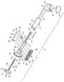
도 2는 도 1에 도시된 록킹가능한 주사기의 분해 사시도이다.
도 3은 도 1의 선 A-A를 따라서 취한 록킹가능한 주사기의 횡단면도로서, 완전한 원위(full distal) 위치의 플런저, 휴지 위치(rest)의 제어 캠, 및 나사산형 주사기의 내부 나사산과 결합되어 전개된 나사산형 세그먼트를 도시한 도면이다.
도 4는 록킹가능한 주사기의 일부의 확대도로서, 전개된 위치에서 나사산형 세그먼트와 조립된 제어 캠을 도시하고 그리고 분해를 돕기 위해서 나사산형 세그먼트의 나사산 섹션들의 절두부(truncation)를 도시한 도면이다.
도 5는 전개된 위치에서 제어 캠 상에 조립된 나사산형 세그먼트의, 도 4의 선 A-A을 따라서 취한, 횡단면도이고 그리고 나사산형 세그먼트의 캠 종동부(follower)에 대한 캠의 표면의 관계를 도시한 도면이다.
도 6은 도 3의 횡단면도와 유사한 횡단면도를 도시하나, 복귀 스프링을 편향시키기 위해서 제어 캠 조작자 제어 표면이 이동된 플런저 원위부 및 나사산형 실린더 내의 완전 후퇴에서 결합된 나사산형 세그먼트 위치를 도시한 도면이다.
도 7은 록킹가능한 주사기의 일부의 사시도로서, 전개된 위치에서 나사산형 세그먼트와 결합된 제어 캠을 도시하고 그리고 나사산형 세그먼트의 스러스트(thrust) 면 그리고 결합 및 후퇴 캠 종동부 모두를 도시한 도면이다.
도 8은 록킹가능한 주사기의 나사산형 세그먼트의 사시도이다.
도 9는 록킹가능한 주사기의 록킹 액추에이터의 사시도로서, 상기 단부가 제어 캠을 제공한다.BRIEF DESCRIPTION OF THE DRAWINGS In addition to the further objects and advantages of the invention, the structure and manner of construction and operation of the invention may best be understood by reference to the following description taken in conjunction with the accompanying drawings, in which like reference numerals identify like elements do.
1 is a side view of a lockable syringe according to an embodiment of the present invention, showing an assembled lockable syringe.
Figure 2 is an exploded perspective view of the lockable syringe shown in Figure 1;
3 is a cross-sectional view of a lockable syringe taken along line AA of FIG. 1, showing a plunger in a fully distal position, a control cam in a rest position, and a threaded deployment screw coupled with the internal threads of the threaded syringe. Fig.
4 is an enlarged view of a portion of a lockable syringe showing the control cam assembled with the threaded segment at the deployed position and showing the truncation of the threaded sections of the threaded segment to aid in disassembly .
Figure 5 is a cross-sectional view of the threaded segment assembled on the control cam in its deployed position, taken along line AA in Figure 4 and showing the relationship of the cam surface to the cam follower of the threaded segment FIG.
Figure 6 shows a cross-sectional view similar to the cross-sectional view of Figure 3, but showing the position of the threaded segment engaged in the fully retracted plunger distal and threaded cylinders with the control cam operator control surface shifted to deflect the return spring.
Figure 7 is a perspective view of a portion of a lockable syringe showing control cams associated with threaded segments at the deployed position and showing both the thrust face of the threaded segment and the engagement and retraction cam follower .
8 is a perspective view of a threaded segment of a lockable syringe.
Figure 9 is a perspective view of a locking actuator of a lockable syringe, said end providing a control cam.
본원 발명이 상이한 형태의 실시예로 구현될 수 있을 것이나, 구체적인 실시예가 도면에 도시되어 있고 그리고 여기에서 구체적으로 설명될 것이며, 본원 개시 내용이 발명의 원리의 예시로서 간주되고 그리고 발명을 설명된 것으로 제한하기 위한 의도가 없다는 것을 이해할 수 있을 것이다.Although the present invention may be embodied in different forms of embodiments, it will be understood by those of ordinary skill in the art that various changes in form and detail may be made therein without departing from the spirit and scope of the present invention as defined by the following claims. It will be understood that there is no intent to limit.
도 1은 본원 발명의 실시예에 따른 록킹가능한 주사기(10)의 측면도인 한편, 도 2는 그 분해도를 제공한다. 도시된 바와 같이, 록킹가능한 주사기(10)가 매우 적은 부품을 가진다. 록킹가능한 주사기(10)의 기본적인 구성요소에는, 플런저(12), 단일형 주사기 본체(14), 나사산형 실린더(16)와 같은 내부 나사산형 부재, 나사산형 세그먼트(18), 및 록킹 액추에이터(20)가 포함된다. 바람직하게, 단일형 주사기 본체(14)의 단부(22)에, 일체형 하우징(24) 내의 압력 게이지 메커니즘(26)을 보호 및 밀봉하기 위한 보호 렌즈(28)뿐만 아니라 압력 게이지 메커니즘(26)을 수용하기 위한 일체형 하우징(24)이 위치된다.Figure 1 is a side view of a
또한, 바람직하게, 단일형 주사기 본체(14)는, 예를 들어, 도 1에 도시된 바와 같이, 호스 및 루어 조립체(32)를 수용하기 위한 일체형 하우징(24)에 근접한 호스 소켓(30)을 포함한다. 단일형 주사기 본체(14)는, 내부 포트(36)(도 3 참조)뿐만 아니라, 호스 소켓(30)에 근접한 주사기 배럴(34)을 포함하고, 상기 내부 포트는 상기 압력 게이지 메커니즘(26)과 상기 주사기 배럴(34) 내의 작업 유체 사이의 소통을 효과적으로 제공한다.The
주사기 배럴(34)은 일반적으로 원통형이고 그리고, 내부에 제공된 통로(38) 내에서, 상기 플런저(12)의 일 단부(42)에 근접하여, 상기 플런저(12) 상에 제공된 피스톤(40)을 수용하도록 구성된다. 도 3 및 6에 도시된 바와 같이, 주사기 배럴(34)의 내부 벽(46)과의 밀봉을 위해서, 밀봉부(44)가 상기 피스톤(40) 상에 제공된다. 또한, 바람직하게, 단일형 주사기 본체(14)가, 나사산형 실린더(16) 내에 배치되는 대체로 원통형인 부분(48)을 포함한다. 도 2에 도시된 바와 같이, 나사산형 실린더(16)가 바람직하게 2개의 절반 세그먼트(50, 52) 형태로 제공되고, 상기 절반 세그먼트는 내부 표면(56) 상에 나사산(54)을 가지는 대체로 원통형인 형상을 함께 형성한다. 나사산형 실린더(16)의 2개의 절반 세그먼트(50, 52)가 짝을 이룰(mated) 때, 상기 나사산형 실린더(16)는 상기 나사산형 실린더(16)의 원위 단부 특징부(58)를 폐쇄 피팅(close fitting)하는 것을 통해서 상기 플런저(12)의 피스톤 단부(42)를 효과적으로 트랩핑(trap)한다. 부가적으로, 단일형 주사기 본체(14)는 나사산형 실린더(16)의 세그먼트(50, 52)를 효과적으로 트랩핑하고, 그에 따라 플런저(12)의 로딩 중에 나사산형 세그먼트(18)에 의해서 부여되는 외측 방사상 힘으로 인해서 세그먼트(50, 52)가 멀어지는 것이 상기 세그먼트(50, 52)를 둘러싸는 단일형 주사기 본체(14)에 의해서 방지된다.The
부가적으로, 일반적으로 나사산형 실린더(16)를 단일형 주사기 본체(14)에 대해서 유지하기 위해서 그리고 나사산형 실린더가 상기 단일형 주사기 본체(14) 내에서 회전하는 것을 방지하기 위해서, 유지(retention) 수단이 단일형 주사기 본체(14)의 대체로 원통형인 부분(48)과 나사산형 실린더(16) 사이에 제공된다. 도 1-3 및 6에 도시된 바와 같이, 유지 수단이, 단일형 주사기 본체(14)의 대체로 원통형인 부분(48) 내의 상응하는 노치(64) 내에 수용되는 나사산형 실린더(16)의 외부 표면(62) 상의 탭(60)(즉, 각각의 절반 세그먼트(50, 52) 상의 탭(60))의 형태로 제공될 수 있을 것이다. 부가적인 또는 대안적인 유지 수단이 나사산형 실린더(16)와 단일형 주사기 본체(14) 사이에 제공될 수 있을 것이다. 예를 들어, 플랜지가 단일형 주사기 본체(14) 내의 상응하는 홈 내의 수용을 위해서 상기 나사산형 실린더(16)의 접촉지지 면(abutting faces)을 따라서 제공될 수 있을 것이다. 그러한 구성은 나사산형 실린더(16)가 단일형 주사기 본체(14)에 대해서 회전하는 것을 방지하는 경향을 가질 뿐만 아니라, 나사산형 실린더(16)의 2개의 절반 세그먼트(50, 52)를 함께 푸싱하는 경향을 가질 수 있을 것이다.In addition, in order to generally hold the threaded
플런저(12)가 상기 플런저(12)의 하나의 단부(42)에 근접하여 피스톤(40)을 가지는 한편, 바람직하게 핸들(66)이 대향 단부(68)에 근접하여 제공된다. 핸들(66)이 조작자의 손에 의해서 제어되도록 성형되고 구성된다. 플런저(12)가 대체로 원통형인 부분(70)을 포함하고, 그리고 대체로 원통형인 부분(70) 내에 수용부(72)가 제공된다. 나사산형 세그먼트(18)가 상기 수용부(72) 내에 수용된다. 상기 수용부(72)의 측벽(74, 76)은 상기 나사산형 세그먼트(18)를 유지하고 안내하는 기능을 한다. 상기 나사산형 세그먼트(18)는, 상기 수용부(72)(도 3 및 6 참조)의 측벽(74, 76)에 대해서 지탱되는 스러스트 면(78, 80)(도 4, 7 및 8 참조)을 포함한다. 상기 나사산형 세그먼트(18)는 상기 수용부(72) 내에서 방사상으로 횡단하도록 구성되고 그리고 나사산형 요소(82)를 포함한다. 상기 나사산형 요소(82)는 바람직하게 절두형이 되고(도 4 및 8에서 참조 번호 '84'로 표시된 바와 같다) 그리고 상기 나사산형 실린더(16)의 내부 표면(56) 상에 제공된 나사산(54)과 선택적으로 결합 및 분리되도록 구성되고, 그에 의해서 록킹가능한 주사기(10)를 록킹 및 언록킹한다. 이는, 이하에서 보다 구체적으로 설명될 것이다. 나사산 요소(82) 및 스러스트 면(78, 80)에 더하여, 나사산형 세그먼트(18)가 또한 전개 캠 종동부(86)(도 5, 7 및 8 참조) 및 후퇴 캠 종동부(88)를 포함한다(도 4, 5, 7, 및 8 참조).A
바람직하게, 플런저(12)의 대체로 원통형인 부분(70)이 또한 노치(90)를 포함하고, 그리고 상기 플런저(12)의 외부 표면(92)이 외측으로 연장하는 플랜지(94)를 제공한다. 상기 플런저(12)의 대체로 원통형인 부분(70)이 상기 록킹 액추에이터(20)를 수용하는 내부 통로(96)를 가진다.The generally
바람직하게, 상기 록킹 액추에이터(20)가 일 단부(100)에서 조작자 인터페이스 표면(98)을, 그리고 타 단부(104)에서 제어 캠(102)을 포함한다(도 9 참조). 상기 록킹 액추에이터(20)는 유지 특징부(108)를 포함하는 샤프트-유사 부분(106)을 포함한다. 이러한 유지 특징부(108)가 플런저(12) 내의 노치(90)와 효과적으로 짝을 이루는 핑거(finger) 형태를 취할 수 있고, 그에 의해서 록킹 액추에이터(20)가 대체로 플런저(12)와 록킹되나, 대체로 미리 결정된 거리로 상기 플런저에 대해서 슬라이딩될 수 있게 되고(즉, 노치(90)의 길이 등에 의존한다), 상기 록킹 액추에이터(20) 상의 핑거(108)는 상기 플런저(12) 내의 노치(90)를 따라서 이동한다. 또한, 바람직하게, 상기 록킹 액추에이터(20)는 상기 록킹 액추에이터(20)를 상기 플런저(12)에 대해서 후퇴된 위치로 바이어스(bias)시키기 위한 스프링 수단(110)을 포함한다. 이러한 스프링 수단(110)은, 상기 록킹 액추에이터(20)를 상기 플런저(12)에 대한 후퇴된 위치로 푸싱하는 경향을 가지는, 원호형의, 복수-세그먼트형의, 가요성 벽(112) 형태로, 조작자 인터페이스 표면(98)에 근접하여 또는 조작자 인터페이스 표면(98) 상에 제공될 수 있을 것이다.Preferably, the locking
상기 록킹 액추에이터(20)의 제어 캠(102)은 전개 캠(114)(도 4-6 및 9 참조) 및 후퇴 캠(116)을 포함하고(도 4, 5, 7 및 9 참조), 상기 양 캠은 나사산형 세그먼트(18)의 캠 종동부(86, 88)와 결합하도록 구성된다. 부가적으로, 제어 캠(102)은 힐(heel)(118)을 포함한다(도 4-7 및 9 참조). 전개 캠(114)은, 도 3에 도시된 바와 같이, 상기 나사산형 세그먼트(18)를 상기 나사산형 실린더(16) 상의 나사산(54)과의 나사형 결합으로 효과적으로 푸싱하도록 구성되고, 그에 의해서 상기 플런저(12)를 상기 나사산형 실린더(16)에 대해서 효과적으로 나사식으로 록킹한다. 이러한 상태에서, 상기 플런저(12)의 핸들(66)이 단일형 주사기 본체(14)에 대해서 푸싱되거나 잡아 당겨질 수 없고 그리고 그 대신에 플런저(12)의 미시적-이동을 실시하도록 회전되어야 하고, 결과적으로 작고, 제어된 압력 변화를 초래하여야 한다. 대조적으로, 후퇴 캠(116)은, 도 6에 도시된 바와 같이, 나사산형 실린더(16) 상의 나사산(54)으로부터 나사산형 세그먼트(18)가 나사식으로 분리되게 허용하도록 구성되고, 그에 의해서 상기 플런저(12)를 상기 나사산형 실린더(16)에 대해서 효과적으로 언록킹시킨다. 이러한 상태에서, 상기 플런저(12)의 핸들(66)이 상기 단일형 주사기 본체(14)에 대해서 푸싱되거나 잡아 당겨질 수 있고, 그에 따라 플런저(12)의 거시적-이동을 실시하여 큰 압력 변화를 초래할 수 있다.The
크고 높은 피치(large high pitch) 제어 나사산의 바람직하지 못한 불이익이 없이 신속한 유체 전달 및 압력 구축(build)을 달성하기 위해서, 여기에서 개시된 록킹가능한 주사기(10)가 바람직하게 (나사산 요소(82) 및 나사산(54)과 관련하여) 복수 리드(lead) 제어 나사산을 구비한다. 그에 따라, 그러한 급격한 피치의 나사산에 일반적인 과다한 나사산 깊이에 대한 어떠한 불이익도 없이, 나사산 피치 또는 완전한 회전 마다 플런저가 이동하는 양이, 예를 들어, 이중(double) 리드 나사산의 경우에 0.100" 내지 바람직하게 0.166" 범위가 될 수 있고 그리고 삼중 리드 나사산의 경우에 심지어 0.250"가 될 수 있다. 이러한 접근 방식에 대한 부가적인 장점은, 투명한(transparent) 그리고 노멀 필링(normal feeling) 방식이 되도록, 예를 들어, 0.083" 피치의 단일 리드 제어 나사산의 경우와 같이, 0.166" 이중 리드 나사산이 플런저의 0.083" 마다 나사 결합 지점을 제공하는 방식이 되도록, 복수 리드 나사산으로 인해서 조작자가 수작업 플런저 이동으로부터 제어된 나사산 결합으로 전이할 수 있게 된다는 것이다. 비교하자면, 이는 0.166"의 플런저 이동 마다 단지 한번 결합하는 0.166" 피치의 단일 리드 나사산을 이용하는 경우에 확실히 사실이 아닐 것이다. 복수 리드 제어 나사산의 추가적인 장점은, 또한 완전한 분리를 위해서, 그러한 얕은(shallower) 깊이가 플런저의 나사산 세그먼트(18)의 적은 횡단방향 후퇴 이동을 필요로 한다는 것이다. 유사한 피치의 보다 깊은 단일 리드 나사산과 대비할 때 얕은 복수 리드 나사산의 또 다른 장점은, 작은 변위 장치가 콤팩트하게 디자인될 수 있도록 하기 위한 전체 장치 둘레 치수(girth)와 관련한 경제성을 제공한다는 것이다.In order to achieve rapid fluid delivery and pressure build-up without undesirable disadvantages of large and high pitch control threads, the
비록 2개의 나사산형 요소(82)를 가지는 것으로서 나사산형 세그먼트(18)가 개시되고 도면에 도시되어 있지만, 사용시에 견디도록 예상되는 로드(load) 및 플런저 회전 마다 희망하는 진행 레이트(rate)에 의해서 지정되는 바에 따라서, 그러한 나사산형 세그먼트(18)가 단지 단일 나사산 요소 또는 심지어 몇 개를 가지는 것으로 제공될 수 있다. 이와 관계 없이, 도 3에 도시된 바와 같이, 나사산형 세그먼트(18)가 수용부(72)의 평행한 측벽(74, 76)에 의해서 유지되고 안내된다. 배럴(34) 내의 피스톤 진행에 저항하는 작업 유체의 압력으로부터 초래되는 로드가 장치(10)의 길이방향 축(도 1에서 수평선(120)으로 표시됨)과 라인을 이루고(in line) 그리고 배럴(34)에 가장 근접한 수용부의 측벽(76)의 면으로부터 나사산형 세그먼트(18)의 인접한 스러스트 면(80)으로, 그리고 이어서 순차적으로 나사산형 실린더(16)의 나사산(54)과 결합된 나사산 요소(82)로, 그리고 최종적으로 단일형 주사기 본체(14)로 전이되어, 나사산형 실린더(16) 상의 유지 특징부들(60)의 단일형 주사기 본체(14) 내의 상응하는 노치(64)와의 결합을 통해서 상기의 것을 수용 및 유지한다. 배럴(34) 내의 진공 조건하의 로딩은 나사산형 세그먼트(18)의 스러스트 면(78)에 대해서 지탱되는 수용부(72)의 대향 측벽(74) 및 반대 방향으로 발생되는 로드 전달의 동일한 체인을 초래한다. 나사산형 실린더(16)에 대한 나사산형 세그먼트(18)의 완전한 그리고 동시적인 결합 및 분리를 보장하기 위해서, 바람직하게 동일한 그러나 나사산형 실린더(16)의 나사산(54)의 크레스트(crest)에 내접하고 터치하는 가상 실린더의 반경을 초과하지 않는 반경에 의해서, 그 나사산 요소(82)가 바람직하게 절두형이 된다(도 4에서 참조 번호 '84'로 표시된 바와 같다). 이러한 절두형은, 나사산형 세그먼트의 나사산 요소(82)의 선단부가 그들의 중심과 동시적으로 나사산형 실린더(16)로부터 해제될 수 있게 보장하고, 이는 해제 중에 나사산 요소의 단부의 마모(fretting)를 방지하고 그리고 횡단방향 이동의 양을 감소시키고 그리고 그에 따라 나사산형 세그먼트(18) 결합 및 분리에 필요한 캠 높이를 감소시킨다. 또한, 횡단면 내의 나사산의 형태의 기울기를 나타내는 각도(122)(도 4 참조)는, 내측으로 후퇴되도록 가압하는 나사산형 세그먼트(18)에 대한 길이방향 스러스트를 부여하는 것에 의해서 로드로부터 해제되는 동안에 나사산형 세그먼트(18)의 후퇴에서 캠을 보조하는 역할을 한다. 이러한 보조의 정도는 나사산 디자인 중에 선택되는 각도(122)에 의해서 제어될 수 있다.Although the threaded
사용시의 유체 압력 생성으로부터 로딩될 때, 도 7에 도시된 바와 같이, 나사산형 세그먼트의 전개 캠 종동부(86)가 전개 캠(114)에 대항하여 프레스하고 그리고 주사기 축(120)에 대해서 횡단방향인 이러한 스러스트는, 캠의 지지 구조물의 힐(118)에 의해서 저항되고(resist), 상기 힐(118)은 상기 힐을 수용하는 플런저 구조물의 내측 벽에 대해서 지탱되고 그리고 다시 그 로드를 나사산형 실린더(16)의 둘러싸는 나사산(54)으로 전달하고, 이어서 상기 나사산(54)은 이러한 횡단방향 로드를 상기 나사산을 둘러싸고 수용하는 단일형 주사기 본체(14)로 전달한다. 나사산형 세그먼트(18)의 후퇴는 로드하의 반응성 스러스트에 의존하지 않으나; 전개 캠(114), 후퇴 캠(116) 및 나사산형 세그먼트(18)의 상호작용이 본질적으로 데스모드로믹(desmodromic)이고 그에 따라, 도 6에 도시된 바와 같이, 나사산형 세그먼트(18)를 내측 또는 외측으로 확실하게(positively) 왕복시킬 수 있고, 그에 따라 (도 6의 화살표(124)에 의해서 표시된 바와 같이) 제어 캠의 조작자 인터페이스 표면(98)이 작동될 때, 나사산형 세그먼트(18)가 내측으로 잡아 당겨지고 그에 의해서 분리시킨다. 이러한 이동은 전개 캠(114) 뒤쪽에 배치된 후퇴 캠(116)을 가지는 나사산형 세그먼트(18)의 후퇴 캠 종동부(88)의 결합을 통해서 달성된다. 제어 캠(102)의 조작자 이동 중에, 제어 캠의 유지 특징부(108)가 플런저(12) 내의 노치(90) 내에서 길이방향으로 자유롭게 횡단하도록 유지된다는 것을 주목하여야 한다.7, the
캠(102)에 의한 전개 또는 후퇴 중에 나사산형 세그먼트(18)의 이동이 개별적인 나사산 형태의 각도까지의 임의 각도가 될 수 있으나, 로드하의 결과적인 벡터 힘의 해소를 위해서, 수용부(72)의 측벽(74, 76)이 바람직하게 플런저(12)의 길이방향 축(120)을 가로질러 나사산형 세그먼트(18)의 이동을 유지하도록 배치된다. 나사산형 세그먼트(18)의 수용부(72) 내의 결합 깊이에 대한 나사산형 세그먼트(18)의 스러스트 면(78, 80)에 걸친 나사산형 세그먼트(18)의 높이의 종횡비는 바람직하게 1.0 또는 그 미만으로 유지되는데, 이는 나사산형 세그먼트(18)가 플런저의 길이방향 축(120)과 가능한 한 수직으로 유지되는 한편 이러한 부품들 사이의 합리적인 동작 간격(clearance)을 유지할 수 있게 보장하기 위한 것이다. 결합 깊이의 증가 없는 이러한 스러스트 면(78, 80)에 걸친 부가적인 높이는, 나사산형 세그먼트(18)의 오정렬 및 재밍(jamming) 증가를 초래할 수 있는 보다 큰 각도형 편향력을 초래할 수 있을 것이다. 이는, 전체 압력 로드 하에서 동작되는 동안에 나사산형 세그먼트(18)의 철수(withdraw)가 요구될 때, 후퇴 캠(116) 상에 보다 큰 로드를 가할 수 있을 것이다. 바람직하지 못한 종횡비로부터 초래되는 다른 관심사항은, 수용부와 세그먼트 구성요소들 사이의 필수적인 동작 간격으로부터 초래되는 허용가능한 각도 이동으로 인해서, 전체 후퇴가 보다 더 어려워질 수 있다는 것이다. 이러한 각도 이동은 나사산형 세그먼트(18)의 나사산(54)의 선단부가 분명하게(squarely) 또는 완전하게 분리되지 않게 유도할 수 있고 그에 따라 나사산형 실린더(16) 내의 드래깅(dragging)에 의해서 자유로운 이동을 방해할 수 있을 것이다.The movement of the threaded
본원 발명의 다른 양태는 장치의 조립 방법을 제공한다. 플런저(12)로 시작하여, 밀봉부(44)를 피스톤(40) 상에 설치하는 단계, 나사산형 세그먼트(18)를 플런저(12)의 수용부(72) 내로 삽입하는 단계, (도 4, 5 및 7에 도시된 바와 같이) 상기 나사산형 세그먼트(18)의 캠 종동부(86, 88)를 전개 및 후퇴 캠(114, 116)과 결합시키기 위해서 제어 캠(102)을 축방향으로 플런저(12) 내로 삽입하는 단계, 제어 캠 복귀 스프링 수단(110)을 상기 플런저(12)와 접촉시키는 단계, 그리고 상기 나사산형 실린더의 유지 특징부(60)가 상기 플런저(12) 상의 노치(64) 내로 록킹될 수 있게 허용하는 단계에 의해서 조립이 달성된다. 희망하는 경우에, 즉 미적인 목적을 위해서, 장식용 커버 링(미도시)이 플런저(12)의 핸들(66) 상으로 프레싱될 수 있을 것이다. 또한, 비록 제어 캠(102)이 여기에서 제어 캠의 조작자 제어 표면(98)과 일체로 형성된 스프링 수단(110)이 구비되어 도시되어 있지만, 플런저(12)와 조작자 제어 표면(98) 사이에 개재된 공통 권선된(wound) 와이어 스프링의 이용이 조작자 제어 표면(98) 상의 일체형 스프링 수단(110)과 동일한 목적을 달성할 수 있다는 것(비록 이렇게 하는 것이 하나의 부가적인 구성요소를 희생할 수 있지만)을 당업자가 이해할 수 있다는 것을 주목하여야 한다. 또 다른 구조물이 이러한 기능 전체를 달성할 수 있다. 전체적인 플런저 하위(sub) 조립체가 나사산형 실린더(16)에 의해서 다음에 전개되고, 그에 의해서 조작자 제어 및 구동 하위-조립체를 완성한다. 일단 플런저(12)가 나사산형 실린더(16)에 의해서 전개되면, 플런저(12)의 피스톤(40) 단부가 나사산형 실린더(16)의 폐쇄 피팅 원위 단부 특징부(58)에 의해서 트랩핑되기 시작하고, 그에 의해서 피스톤(40)이 나사산형 실린더(16)로부터 제거되는 것이 방지된다. 이어서, 제어 및 구동 조립체를 축방향으로 홈(home)으로 프레싱하기에 앞서서 먼저 피스톤(40) 및 밀봉부(44)를 배럴(34)과 결합시켜, 나사산형 실린더(16)가 주사기 본체(14) 내에 꼭 맞게(snugly) 캡쳐되고 그리고 그 스냅(snap) 타입 유지 특징부(60)가 단일형 주사기 본체(14) 내에 제공된 상응하는 노치(64)와 결합하는 것에 의해서 제 위치에서 고정됨으로써, 이러한 완성된 제어 및 구동 조립체가 단일형 주사기 본체(14) 내로 삽입된다. 주사기 작동 구성요소의 설치에 이어서, 압력 게이지 메커니즘(26)이 단일형 주사기 본체(14)의 단부(22)에 근접한 그 일체형 하우징(24) 내에 고정되고, 상기 보호용 렌즈(28)가 그 위의 위치로 스냅 결합되고, 그리고 루어 구비형(Luer equipped) 호스 조립체(32)가 수용 소켓(30) 내로 본딩된다. 희망하는 경우에, 압력 게이지 메커니즘(26) 및 루어 구비형 호스 조립체(32) 중 어느 하나 또는 양자 모두가, 조작자 제어 및 구동 하위 조립체의 설치 절차에 앞서서 먼저, 단일형 주사기 본체(14)에 조립될 수 있을 것이다.Another aspect of the present invention provides a method of assembling an apparatus. Starting with the
본원 발명의 구체적인 실시예를 도시하고 설명하였지만, 본원 발명의 사상 및 범위로부터 벗어나지 않고도, 당업자가 많은 수정들을 안출할 수 있다는 것을 이해할 수 있을 것이다.While particular embodiments of the invention have been illustrated and described, it will be appreciated that many modifications may be devised by those skilled in the art without departing from the spirit and scope of the invention.
Claims (17)
Translated fromKorean내부 나사산형 부재;
플런저로서, 상기 플런저의 적어도 일부가 상기 내부 나사산형 부재 내에 위치되는, 플런저;
외부 나사산을 가지는 부재로서, 상기 플런저에 의해서 반송되는 부재; 및
상기 플런저 내로 연장하고 그리고 외부 나사산을 가지는 부재와 결합하는 록킹 액추에이터로서, 상기 록킹 액추에이터가 상기 외부 나사산을 가지는 부재를 상기 내부 나사산형 부재로부터 분리시키도록 작동할 수 있고, 그에 의해서, 상기 플런저를 회전시키지 않고, 상기 플런저가 상기 내부 나사산형 부재에 대해서 슬라이딩될 수 있게 허용하는, 록킹 액추에이터를 포함하는, 록킹가능한 주사기.A lockable syringe for pressurizing a medical device, comprising:
Internal threaded member;
A plunger, wherein at least a portion of the plunger is located within the internal threaded member;
1. A member having an external thread, the member being carried by the plunger; And
A locking actuator extending into the plunger and engaging a member having an external thread, the locking actuator being operable to disengage the member having the external thread from the internal threaded member, thereby rotating the plunger And allowing the plunger to slide relative to the internal threaded member without causing the plunger to slide relative to the internal threaded member.
상기 외부 나사산을 가지는 부재가 상기 플런저 상의 수용부 내에 배치되는 나사산형 세그먼트를 포함하는, 록킹가능한 주사기.The method according to claim 1,
Wherein the member having the external threads comprises a threaded segment disposed within the receptacle on the plunger.
상기 록킹 액추에이터가 상기 외부 나사산을 가지는 부재를 상기 내부 나사산형 부재와 결합시키기 위해서 푸싱가능하고, 그리고 상기 록킹 액추에이터가 상기 플런저의 외부로 바이어스되는, 록킹가능한 주사기.The method according to claim 1,
Wherein the locking actuator is pushable to engage a member having the external threads with the internal threaded member, and wherein the locking actuator is biased out of the plunger.
상기 플런저가 슬롯을 포함하고, 그리고 상기 록킹 액추에이터가 상기 슬롯내에서 결합하고 올라타는(ride) 핑거를 포함하는, 록킹가능한 주사기.The method according to claim 1,
Wherein the plunger includes a slot and the locking actuator includes a finger that engages and rides within the slot.
단일형 주사기 본체를 더 포함하고, 상기 내부 나사산형 부재가 상기 단일형 주사기 본체 내에 배치되는, 록킹가능한 주사기.The method according to claim 1,
Further comprising a single syringe body, wherein the internal threaded member is disposed within the single syringe body.
상기 단일형 주사기 본체가 통로를 포함하고, 상기 플런저가 피스톤을 포함하고, 상기 피스톤이 상기 단일형 주사기 본체의 통로 내에서 이동가능한, 록킹가능한 주사기.6. The method of claim 5,
Wherein the single syringe body includes a passageway, the plunger includes a piston, and the piston is movable within a passageway of the single syringe body.
상기 내부 나사산형 부재가 상기 단일형 주사기 본체에 대해서 실질적으로 회전되지 않도록 상기 내부 나사산형 부재를 상기 단일형 주사기 본체에 대해서 유지하기 위한 유지 수단을 더 포함하는, 록킹가능한 주사기.6. The method of claim 5,
Further comprising retaining means for retaining the internal threaded member against the single syringe body such that the internal threaded member is not substantially rotated relative to the single syringe body.
상기 피스톤이 일 단부에서 핸들을 그리고 대향 단부에서 피스톤을 포함하는, 록킹가능한 주사기.The method according to claim 1,
Wherein the piston comprises a handle at one end and a piston at an opposite end.
상기 록킹 액추에이터가 일 단부에서 조작자 인터페이스 표면을 그리고 타 단부에서 제어 캠을 포함하는, 록킹가능한 주사기.The method according to claim 1,
Wherein the locking actuator comprises an operator interface surface at one end and a control cam at the other end.
상기 록킹 액추에이터의 조작자 인터페이스 표면이, 상기 외부 나사산을 가지는 부재가 상기 내부 나사산형 부재로부터 분리되도록 상기 플런저의 외부로 상기 록킹 액추에이터를 바이어스시키도록 구성된 스프링 수단을 포함하는, 록킹가능한 주사기.10. The method of claim 9,
Wherein the actuator interface of the locking actuator includes spring means configured to bias the locking actuator out of the plunger such that a member having the external thread is separated from the internal threaded member.
상기 제어 캠이 전개 캠 및 후퇴 캠을 포함하는, 록킹가능한 주사기.10. The method of claim 9,
Wherein the control cam includes a deployment cam and a retraction cam.
상기 전개 캠은 상기 외부 나사산을 가지는 부재를 상기 내부 나사산형 부재와의 나사산형 결합으로 푸싱하여 상기 플런저를 록킹하도록 구성되고, 그리고 상기 후퇴 캠은 상기 외부 나사산을 가지는 부재가 상기 내부 나사산형 부재로부터 나사식으로 분리되게 허용하여 상기 플런저를 언록킹시키도록 구성되는, 록킹가능한 주사기.12. The method of claim 11,
Wherein the deployment cam is configured to push the member having the external thread into the threaded engagement with the internal threaded member to lock the plunger, and the retraction cam is configured such that the member having the external thread is withdrawn from the internal threaded member Wherein the plunger is configured to unlock the plunger by allowing the catheter to be threadably disengaged.
상기 외부 나사산을 가지는 부재가 전개 캠 종동부 및 후퇴 캠 종동부를 포함하는, 록킹가능한 주사기.13. The method of claim 12,
Wherein the member having an external thread comprises an deploying cam follower and a retracting cam follower.
상기 플런저가 길이방향 축을 가지고, 상기 플런저의 길이방향 축의 횡단방향으로 상기 나사산형 부재의 이동을 유지하는 경향을 가지는 측벽에 의해서 상기 수용부가 형성되는, 록킹가능한 주사기.3. The method of claim 2,
Wherein said receptacle is formed by sidewalls having a longitudinal axis with said plunger and a tendency to maintain movement of said threaded member in a direction transverse to the longitudinal axis of said plunger.
단일형 주사기 본체를 더 포함하고, 상기 내부 나사산형 부재가 상기 단일형 주사기 본체 내에 배치되는 복수의 세그먼트를 포함하고, 상기 플런저의 로딩 중에 상기 나사산형 세그먼트에 의해서 부여되는 외측 방사상 힘으로 인해서 상기 내부 나사산형 부재의 세그먼트들이 멀어지는 것이 상기 내부 나사산형 부재의 세그먼트를 둘러싸는 상기 단일형 주사기 본체에 의해서 방지되는, 록킹가능한 주사기.The method according to claim 1,
Wherein the inner threaded member comprises a plurality of segments disposed within the single syringe body and wherein an outer radial force imparted by the threaded segment during loading of the plunger causes the inner threaded member Wherein removal of the segments of the member is prevented by the single syringe body surrounding the segment of the internal threaded member.
압력 게이지 메커니즘을 수용하기 위한 내부 게이지 하우징 및 상기 압력 게이지 메커니즘으로 상기 주사기 내의 작업 유체를 전달하기 위한 내부 유체 소통 포트를 포함하는 단일형 주사기 본체를 더 포함하는, 록킹가능한 주사기.The method according to claim 1,
Further comprising a single syringe body including an inner gauge housing for receiving a pressure gauge mechanism and an inner fluid communication port for delivering a working fluid in the syringe to the pressure gauge mechanism.
주사기 본체를 제공하는 단계와,
내부 나사산형 부재를 제공하는 단계와,
플런저를 제공하는 단계와,
외부 나사산을 가지는 부재를 제공하는 단계와,
상기 외부 나사산을 가지는 부재를 상기 플런저와 결합시키는 단계와,
록킹 액추에이터가 상기 외부 나사산을 가지는 부재와 결합하도록 록킹 액추에이터를 상기 플런저 내로 삽입하는 단계와,
상기 내부 나사산형 부재가 상기 플런저 주위로 형성되어 하위조립체를 형성하도록, 상기 내부 나사산형 부재를 조립하는 단계와,
상기 내부 나사산형 부재가 상기 주사기 본체와 결합하도록 그리고 상기 주사기 본체에 대해서 실질적으로 회전되는 것이 방지되도록, 상기 하위조립체를 상기 주사기 본체 내로 삽입하는 단계를 포함하는, 록킹가능한 주사기의 조립 방법.A method of assembling a lockable syringe, comprising:
Providing a syringe body,
Providing an internal threaded member;
Providing a plunger,
Providing a member having an external thread,
Coupling a member having the external threads with the plunger;
Inserting a locking actuator into the plunger such that the locking actuator engages a member having the external threads;
Assembling the internal threaded member such that the internal threaded member is formed around the plunger to form a subassembly;
Inserting the subassembly into the syringe body such that the internal threaded member is prevented from engaging the syringe body and being substantially rotated relative to the syringe body.
Applications Claiming Priority (4)
| Application Number | Priority Date | Filing Date | Title |
|---|---|---|---|
| US201361824243P | 2013-05-16 | 2013-05-16 | |
| US61/824,243 | 2013-05-16 | ||
| US14/204,980US9492643B2 (en) | 2013-05-16 | 2014-03-11 | Lockable syringe and method of assembling same |
| US14/204,980 | 2014-03-11 |
Publications (2)
| Publication Number | Publication Date |
|---|---|
| KR20140135633Atrue KR20140135633A (en) | 2014-11-26 |
| KR102055642B1 KR102055642B1 (en) | 2020-01-22 |
Family
ID=50624498
Family Applications (1)
| Application Number | Title | Priority Date | Filing Date |
|---|---|---|---|
| KR1020140056957AActiveKR102055642B1 (en) | 2013-05-16 | 2014-05-13 | Lockable syringe and method of assembling same |
Country Status (14)
| Country | Link |
|---|---|
| US (1) | US9492643B2 (en) |
| EP (1) | EP2803381B1 (en) |
| JP (1) | JP6415846B2 (en) |
| KR (1) | KR102055642B1 (en) |
| CN (1) | CN104162224B (en) |
| AU (1) | AU2014202455B2 (en) |
| BR (1) | BR102014011513B1 (en) |
| CA (1) | CA2851769C (en) |
| ES (1) | ES2728753T3 (en) |
| HU (1) | HUE044385T2 (en) |
| IN (1) | IN2014CH02382A (en) |
| MX (1) | MX350095B (en) |
| PL (1) | PL2803381T3 (en) |
| RU (1) | RU2666880C2 (en) |
Families Citing this family (15)
| Publication number | Priority date | Publication date | Assignee | Title |
|---|---|---|---|---|
| US9724479B2 (en) | 2012-07-16 | 2017-08-08 | Accunit, Llc | Handheld medical substance dispensing system, apparatus and methods |
| US9114216B2 (en) | 2012-07-16 | 2015-08-25 | Accunit, Llc | Handheld medical substance dispensing system, apparatus and methods |
| FR3043561B1 (en)* | 2015-11-12 | 2021-11-26 | Guerbet Sa | SYRINGE |
| US11202890B2 (en) | 2016-02-25 | 2021-12-21 | Atrion Medical Products, Inc. | Actuating mechanism, method of operation and assembly for fluid displacement and pressurizing device |
| CN106438329B (en)* | 2016-10-20 | 2017-06-16 | 深圳市业聚实业有限公司 | Compression pump |
| US11691432B2 (en) | 2018-02-26 | 2023-07-04 | Hewlett-Packard Development Company, L.P. | Air purger with plunger |
| JP7675520B2 (en)* | 2018-05-22 | 2025-05-13 | シー・アール・バード・インコーポレーテッド | System and method for sterile urine sampling - Patents.com |
| KR102302552B1 (en)* | 2019-03-13 | 2021-09-16 | (주)휴바이오메드 | Medical syringe |
| WO2020252459A1 (en)* | 2019-06-13 | 2020-12-17 | Kim Medical Design, Llc | In-line medication crusher for feeding tubes |
| RU196282U1 (en)* | 2019-12-11 | 2020-02-21 | Общество с ограниченной ответственностью "МИМ" | SYRINGE FOR PRESSURE IN A CYLINDER CATHETER |
| RU2733692C1 (en)* | 2020-01-24 | 2020-10-06 | Александр Александрович Петров | Syringe pen |
| CN112169857B (en)* | 2020-10-19 | 2021-10-26 | 西南医科大学 | Rapid arranging and storing box for pipette heads of liquid-transfering gun and using method |
| US11980729B2 (en) | 2020-12-18 | 2024-05-14 | Atrion Medical Products, Inc. | Actuating mechanism for fluid displacement and pressurizing devices |
| CN113262360B (en)* | 2021-04-30 | 2022-11-11 | 温州医科大学附属第一医院 | Dual-lumen syringe |
| CN114099864B (en)* | 2021-10-20 | 2024-01-30 | 华中农业大学 | Needleless injector capable of automatically adjusting injection pressure |
Citations (5)
| Publication number | Priority date | Publication date | Assignee | Title |
|---|---|---|---|---|
| US5057078A (en)* | 1989-03-17 | 1991-10-15 | Merit Medical Systems, Inc. | Locking syringe |
| US5163904A (en)* | 1991-11-12 | 1992-11-17 | Merit Medical Systems, Inc. | Syringe apparatus with attached pressure gauge |
| US5209732A (en)* | 1989-03-17 | 1993-05-11 | Merit Medical Systems, Inc. | Locking syringe with thread-release lock |
| US5279563A (en)* | 1990-10-29 | 1994-01-18 | B. Braun Medical, Inc. | Digital display for an inflation system for a balloon catheter |
| JP2013085911A (en)* | 2011-10-21 | 2013-05-13 | Create Medic Co Ltd | Syringe operating device |
Family Cites Families (11)
| Publication number | Priority date | Publication date | Assignee | Title |
|---|---|---|---|---|
| US4832692A (en)* | 1986-10-14 | 1989-05-23 | Cordis Corporation | Inflation syringe assembly for percutaneous transluminal angioplasty |
| US4919121A (en) | 1989-02-06 | 1990-04-24 | Schneider (Usa) Inc., A Pfizer Company | Inflation device for angioplasty catheter |
| US5047015A (en) | 1989-03-17 | 1991-09-10 | Merit Medical Systems, Inc. | Locking syringe |
| US5160327A (en)* | 1991-05-31 | 1992-11-03 | Vance Products Incorporated | Rotational pressure drive for a medical syringe |
| AU2605597A (en) | 1996-05-21 | 1997-12-09 | Merit Medical Systems, Inc. | Reinforced locking syringe |
| US6796959B2 (en) | 2001-03-19 | 2004-09-28 | Atrion Medical Products, Inc. | Actuating mechanism for fluid displacement and pressurizing device |
| ITVI20020140A1 (en)* | 2002-06-26 | 2003-12-29 | Tecres Spa | DEVICE FOR THE MANUAL DOSING OF A MEDICAL FLUID, PARTICULARLY BONE CEMENT |
| US7207971B2 (en) | 2002-12-23 | 2007-04-24 | Boston Scientific Scimed, Inc. | Pressure relief devices for use with balloon catheters |
| FR2850286B1 (en) | 2003-01-27 | 2005-12-16 | Sedat | INFLATION DEVICE OF BALLOON |
| US8191457B2 (en)* | 2008-11-13 | 2012-06-05 | Atrion Medical Products, Inc. | Actuating mechanism for fluid displacement and pressurizing device |
| WO2014039945A1 (en)* | 2012-09-10 | 2014-03-13 | Acclarent, Inc. | Inflator for dilation of anatomical passageway |
- 2014
- 2014-03-11USUS14/204,980patent/US9492643B2/enactiveActive
- 2014-05-01JPJP2014094527Apatent/JP6415846B2/enactiveActive
- 2014-05-01PLPL14166784Tpatent/PL2803381T3/enunknown
- 2014-05-01HUHUE14166784patent/HUE044385T2/enunknown
- 2014-05-01ESES14166784Tpatent/ES2728753T3/enactiveActive
- 2014-05-01EPEP14166784.0Apatent/EP2803381B1/enactiveActive
- 2014-05-06RURU2014118114Apatent/RU2666880C2/enactive
- 2014-05-06AUAU2014202455Apatent/AU2014202455B2/enactiveActive
- 2014-05-13ININ2382CH2014patent/IN2014CH02382A/enunknown
- 2014-05-13KRKR1020140056957Apatent/KR102055642B1/enactiveActive
- 2014-05-13MXMX2014005808Apatent/MX350095B/enactiveIP Right Grant
- 2014-05-13BRBR102014011513-7Apatent/BR102014011513B1/enactiveIP Right Grant
- 2014-05-14CACA2851769Apatent/CA2851769C/enactiveActive
- 2014-05-16CNCN201410209179.1Apatent/CN104162224B/enactiveActive
Patent Citations (5)
| Publication number | Priority date | Publication date | Assignee | Title |
|---|---|---|---|---|
| US5057078A (en)* | 1989-03-17 | 1991-10-15 | Merit Medical Systems, Inc. | Locking syringe |
| US5209732A (en)* | 1989-03-17 | 1993-05-11 | Merit Medical Systems, Inc. | Locking syringe with thread-release lock |
| US5279563A (en)* | 1990-10-29 | 1994-01-18 | B. Braun Medical, Inc. | Digital display for an inflation system for a balloon catheter |
| US5163904A (en)* | 1991-11-12 | 1992-11-17 | Merit Medical Systems, Inc. | Syringe apparatus with attached pressure gauge |
| JP2013085911A (en)* | 2011-10-21 | 2013-05-13 | Create Medic Co Ltd | Syringe operating device |
Also Published As
| Publication number | Publication date |
|---|---|
| EP2803381B1 (en) | 2019-03-27 |
| IN2014CH02382A (en) | 2015-07-03 |
| EP2803381A1 (en) | 2014-11-19 |
| MX350095B (en) | 2017-08-25 |
| MX2014005808A (en) | 2014-11-21 |
| KR102055642B1 (en) | 2020-01-22 |
| PL2803381T3 (en) | 2019-09-30 |
| CA2851769C (en) | 2018-02-13 |
| CA2851769A1 (en) | 2014-11-16 |
| AU2014202455B2 (en) | 2018-07-19 |
| JP6415846B2 (en) | 2018-10-31 |
| US20140343490A1 (en) | 2014-11-20 |
| BR102014011513A2 (en) | 2015-10-13 |
| BR102014011513B1 (en) | 2021-09-21 |
| HUE044385T2 (en) | 2019-10-28 |
| JP2014223301A (en) | 2014-12-04 |
| RU2014118114A (en) | 2015-11-20 |
| ES2728753T3 (en) | 2019-10-28 |
| CN104162224A (en) | 2014-11-26 |
| RU2666880C2 (en) | 2018-09-12 |
| AU2014202455A1 (en) | 2014-12-04 |
| CN104162224B (en) | 2019-06-04 |
| US9492643B2 (en) | 2016-11-15 |
Similar Documents
| Publication | Publication Date | Title |
|---|---|---|
| KR20140135633A (en) | Lockable syringe and method of assembling same | |
| JP6526141B2 (en) | Dual chamber passive pull-in needle syringe | |
| JP5000489B2 (en) | Injection device | |
| EP2175917B1 (en) | Injection device with locking mechanism for syringe carrier | |
| CN101252962B (en) | Needle shroud assembly | |
| US20100280460A1 (en) | Automatic Injection Device | |
| JP2020501675A (en) | Safety needle device | |
| EP2265308B1 (en) | Needle protection assembly with radially movable locking element | |
| US20090043263A1 (en) | Retractable hypodermic syringe | |
| RU2534405C2 (en) | Syringe with retractable needle and cutting crown | |
| CN109641104A (en) | Automatic injection device with preferred arrangement | |
| EP4058102B1 (en) | Medicament delivery device | |
| JP7178102B2 (en) | safety syringe | |
| KR20230121599A (en) | Actuation mechanism for fluid displacement and pressurization devices | |
| JP2008142565A (en) | Single-use retractable syringe equipped with positive needle holding | |
| GB2501412A (en) | A sharps retraction device | |
| CN108348680A (en) | The system and method for the fluid injector engaged with pressure jacket and syringe cap | |
| GB2508490A (en) | A sharps retraction device |
Legal Events
| Date | Code | Title | Description |
|---|---|---|---|
| PA0109 | Patent application | Patent event code:PA01091R01D Comment text:Patent Application Patent event date:20140513 | |
| PG1501 | Laying open of application | ||
| A201 | Request for examination | ||
| PA0201 | Request for examination | Patent event code:PA02012R01D Patent event date:20170518 Comment text:Request for Examination of Application Patent event code:PA02011R01I Patent event date:20140513 Comment text:Patent Application | |
| E902 | Notification of reason for refusal | ||
| PE0902 | Notice of grounds for rejection | Comment text:Notification of reason for refusal Patent event date:20190219 Patent event code:PE09021S01D | |
| E701 | Decision to grant or registration of patent right | ||
| PE0701 | Decision of registration | Patent event code:PE07011S01D Comment text:Decision to Grant Registration Patent event date:20191127 | |
| GRNT | Written decision to grant | ||
| PR0701 | Registration of establishment | Comment text:Registration of Establishment Patent event date:20191209 Patent event code:PR07011E01D | |
| PR1002 | Payment of registration fee | Payment date:20191210 End annual number:3 Start annual number:1 | |
| PG1601 | Publication of registration | ||
| PR1001 | Payment of annual fee | Payment date:20221124 Start annual number:4 End annual number:4 | |
| PR1001 | Payment of annual fee | Payment date:20241126 Start annual number:6 End annual number:6 |