KR20140134561A - Apparatus and method for transmitting or receiving control channel including differential resource allocation information - Google Patents
Apparatus and method for transmitting or receiving control channel including differential resource allocation informationDownload PDFInfo
- Publication number
- KR20140134561A KR20140134561AKR1020130054629AKR20130054629AKR20140134561AKR 20140134561 AKR20140134561 AKR 20140134561AKR 1020130054629 AKR1020130054629 AKR 1020130054629AKR 20130054629 AKR20130054629 AKR 20130054629AKR 20140134561 AKR20140134561 AKR 20140134561A
- Authority
- KR
- South Korea
- Prior art keywords
- resource allocation
- differential
- field
- allocation field
- resource
- Prior art date
- Legal status (The legal status is an assumption and is not a legal conclusion. Google has not performed a legal analysis and makes no representation as to the accuracy of the status listed.)
- Withdrawn
Links
- 238000013468resource allocationMethods0.000titleclaimsabstractdescription361
- 238000000034methodMethods0.000titleclaimsabstractdescription62
- 230000011664signalingEffects0.000claimsabstractdescription29
- 230000005540biological transmissionEffects0.000claimsabstractdescription20
- 230000000295complement effectEffects0.000claimsdescription23
- 230000008859changeEffects0.000claimsdescription19
- 101000741965Homo sapiens Inactive tyrosine-protein kinase PRAG1Proteins0.000claimsdescription3
- 102100038659Inactive tyrosine-protein kinase PRAG1Human genes0.000claimsdescription3
- 238000004891communicationMethods0.000description18
- 208000036357GUCY2D-related recessive retinopathyDiseases0.000description16
- 238000010586diagramMethods0.000description14
- 230000002776aggregationEffects0.000description4
- 238000004220aggregationMethods0.000description4
- 230000008569processEffects0.000description4
- 230000001413cellular effectEffects0.000description3
- 230000001174ascending effectEffects0.000description2
- 230000009466transformationEffects0.000description2
- 238000004364calculation methodMethods0.000description1
- 230000006835compressionEffects0.000description1
- 238000007906compressionMethods0.000description1
- 230000001419dependent effectEffects0.000description1
- 230000004069differentiationEffects0.000description1
- 238000005259measurementMethods0.000description1
- 238000012986modificationMethods0.000description1
- 230000004048modificationEffects0.000description1
- 230000000644propagated effectEffects0.000description1
- 230000009467reductionEffects0.000description1
- 230000003068static effectEffects0.000description1
- 230000001131transforming effectEffects0.000description1
- 238000011144upstream manufacturingMethods0.000description1
Images


Classifications
- H—ELECTRICITY
- H04—ELECTRIC COMMUNICATION TECHNIQUE
- H04W—WIRELESS COMMUNICATION NETWORKS
- H04W72/00—Local resource management
- H04W72/20—Control channels or signalling for resource management
- H04W72/23—Control channels or signalling for resource management in the downlink direction of a wireless link, i.e. towards a terminal
- H04W72/231—Control channels or signalling for resource management in the downlink direction of a wireless link, i.e. towards a terminal the control data signalling from the layers above the physical layer, e.g. RRC or MAC-CE signalling
- H—ELECTRICITY
- H04—ELECTRIC COMMUNICATION TECHNIQUE
- H04L—TRANSMISSION OF DIGITAL INFORMATION, e.g. TELEGRAPHIC COMMUNICATION
- H04L5/00—Arrangements affording multiple use of the transmission path
- H04L5/0091—Signalling for the administration of the divided path, e.g. signalling of configuration information
- H04L5/0096—Indication of changes in allocation
- H—ELECTRICITY
- H04—ELECTRIC COMMUNICATION TECHNIQUE
- H04L—TRANSMISSION OF DIGITAL INFORMATION, e.g. TELEGRAPHIC COMMUNICATION
- H04L1/00—Arrangements for detecting or preventing errors in the information received
- H04L1/0001—Systems modifying transmission characteristics according to link quality, e.g. power backoff
- H04L1/0015—Systems modifying transmission characteristics according to link quality, e.g. power backoff characterised by the adaptation strategy
- H04L1/0019—Systems modifying transmission characteristics according to link quality, e.g. power backoff characterised by the adaptation strategy in which mode-switching is based on a statistical approach
- H04L1/002—Algorithms with memory of the previous states, e.g. Markovian models
- H—ELECTRICITY
- H04—ELECTRIC COMMUNICATION TECHNIQUE
- H04L—TRANSMISSION OF DIGITAL INFORMATION, e.g. TELEGRAPHIC COMMUNICATION
- H04L1/00—Arrangements for detecting or preventing errors in the information received
- H04L1/12—Arrangements for detecting or preventing errors in the information received by using return channel
- H04L1/16—Arrangements for detecting or preventing errors in the information received by using return channel in which the return channel carries supervisory signals, e.g. repetition request signals
- H04L1/18—Automatic repetition systems, e.g. Van Duuren systems
- H04L1/1829—Arrangements specially adapted for the receiver end
- H04L1/1861—Physical mapping arrangements
- H—ELECTRICITY
- H04—ELECTRIC COMMUNICATION TECHNIQUE
- H04L—TRANSMISSION OF DIGITAL INFORMATION, e.g. TELEGRAPHIC COMMUNICATION
- H04L1/00—Arrangements for detecting or preventing errors in the information received
- H04L1/12—Arrangements for detecting or preventing errors in the information received by using return channel
- H04L1/16—Arrangements for detecting or preventing errors in the information received by using return channel in which the return channel carries supervisory signals, e.g. repetition request signals
- H04L1/18—Automatic repetition systems, e.g. Van Duuren systems
- H04L1/1867—Arrangements specially adapted for the transmitter end
- H—ELECTRICITY
- H04—ELECTRIC COMMUNICATION TECHNIQUE
- H04L—TRANSMISSION OF DIGITAL INFORMATION, e.g. TELEGRAPHIC COMMUNICATION
- H04L5/00—Arrangements affording multiple use of the transmission path
- H04L5/003—Arrangements for allocating sub-channels of the transmission path
- H04L5/0053—Allocation of signalling, i.e. of overhead other than pilot signals
- H—ELECTRICITY
- H04—ELECTRIC COMMUNICATION TECHNIQUE
- H04W—WIRELESS COMMUNICATION NETWORKS
- H04W72/00—Local resource management
- H04W72/12—Wireless traffic scheduling
- H04W72/1263—Mapping of traffic onto schedule, e.g. scheduled allocation or multiplexing of flows
- H04W72/1268—Mapping of traffic onto schedule, e.g. scheduled allocation or multiplexing of flows of uplink data flows
- H—ELECTRICITY
- H04—ELECTRIC COMMUNICATION TECHNIQUE
- H04W—WIRELESS COMMUNICATION NETWORKS
- H04W72/00—Local resource management
- H04W72/50—Allocation or scheduling criteria for wireless resources
- H04W72/54—Allocation or scheduling criteria for wireless resources based on quality criteria
- H—ELECTRICITY
- H04—ELECTRIC COMMUNICATION TECHNIQUE
- H04W—WIRELESS COMMUNICATION NETWORKS
- H04W88/00—Devices specially adapted for wireless communication networks, e.g. terminals, base stations or access point devices
- H04W88/02—Terminal devices
- H04W88/022—Selective call receivers
- H04W88/025—Selective call decoders
- H—ELECTRICITY
- H04—ELECTRIC COMMUNICATION TECHNIQUE
- H04W—WIRELESS COMMUNICATION NETWORKS
- H04W72/00—Local resource management
- H04W72/04—Wireless resource allocation
Landscapes
- Engineering & Computer Science (AREA)
- Signal Processing (AREA)
- Computer Networks & Wireless Communication (AREA)
- Quality & Reliability (AREA)
- Artificial Intelligence (AREA)
- Physics & Mathematics (AREA)
- Probability & Statistics with Applications (AREA)
- Mobile Radio Communication Systems (AREA)
Abstract
Translated fromKoreanDescription
Translated fromKorean본 발명은 무선통신 시스템에 관한 것으로서, 보다 상세하게는 차동 기법을 활용한 자원할당방법 및 장치에 관한 것이다.BACKGROUND OF THE
다중 사용자(multiple user: MU)-MIMO 방식이나 연계된 다중 점(CoMP) 방식과 같이 PDCCH의 개수를 많이 요구하는 통신방식에서는 제어영역을 확대하는 방안이 있다. 제어영역의 확장은 데이터영역(예, PDSCH 영역)으로의 확장을 의미하고 결과적으로 PDSCH 영역의 축소를 의미한다. 따라서, 결과적으로 PDSCH 영역의 용량(capacity)를 줄일 수 있기 때문에 기존의 제어영역을 효율적으로 활용하는 방안이 필요하다. 이에 따라 하나의 PDCCH를 이용하여 전송점(transmitting point)에서 하나 이상의 PDSCH들을 위한 자원을 할당하는 방법이 요구된다. 또한, 전송점과 대응되는 개념으로서 수신점(reception point)이 별도로 정의될 수 있다. 하향링크에서 전송점은 요소 반송파, 또는 셀, 또는 기지국(예, 매크로 기지국, 피코 기지국(Pico eNB), 펨토 기지국(Femto eNB)), 또는 원격 무선 헤드(remote radio head: RRH) 중 어느 것으로 정의될 수 있고, 수신점은 요소 반송파, 또는 셀 또는 단말을 포함한다. 상향링크에서 전송점은 요소 반송파, 또는 셀, 또는 단말을 포함하고, 수신점은 요소 반송파, 또는 셀, 또는 기지국(매크로 기지국, 피코 기지국, 펨토 기지국 등), 또는 원격 무선 헤드 중 어느 것으로 정의될 수 있다.In a communication scheme requiring a large number of PDCCHs, such as a multiple user (MU) -MIMO scheme or an associated multipoint (CoMP) scheme, there is a plan to expand the control area. The expansion of the control region implies the extension to the data region (e.g., the PDSCH region) and consequently the reduction of the PDSCH region. As a result, since the capacity of the PDSCH region can be reduced, it is necessary to utilize the existing control region efficiently. Accordingly, a method of allocating resources for one or more PDSCHs at a transmitting point using one PDCCH is required. In addition, a reception point may be defined as a concept corresponding to a transmission point. The transmission point in the downlink is defined as either an elementary carrier or a cell or a base station (eg, a macro base station, a pico base station (Pico eNB), a femto base station (Femto eNB), or a remote radio head (RRH) And the receiving point includes an elementary carrier, or a cell or a terminal. The transmission point in the uplink includes an elementary carrier or a cell or a terminal and the reception point may be defined as either an elementary carrier or a cell or a base station (macro base station, pico base station, femto base station, etc.) .
일반적으로, 무선통신 시스템에서는 제어영역(control region)내에서 물리 하향링크 제어채널(Physical Downlink Control Channel: PDCCH)을 전송한다. 물리 하향링크 제어채널에는 상향링크 또는 하향링크 통신을 위한 제어정보가 맵핑된다. 이러한 제어정보는 단말에 특정한(specific) 무선 자원(radio resource)을 할당하는 자원할당 정보를 포함한다.Generally, in a wireless communication system, a physical downlink control channel (PDCCH) is transmitted in a control region. Control information for uplink or downlink communication is mapped to the physical downlink control channel. The control information includes resource allocation information for allocating specific radio resources to the UE.
또한, 물리제어채널의 용량증가를 위해서 PDSCH영역에서 제어정보를 송수신하도록 ePDCCH(enhanced PDCCH)가 제안된다. ePDCCH는 PDSCH영역에 위치하지만 제어정보를 송수신할 수 있는 물리제어채널 형태이다.Also, an ePDCCH (enhanced PDCCH) is proposed to transmit / receive control information in the PDSCH region in order to increase the capacity of the physical control channel. The ePDCCH is a type of physical control channel that is located in the PDSCH area but can transmit / receive control information.
무선 자원은 시간-주파수 평면에서 분할된 블록, 즉 자원 블록(resource block: RB)으로 표현될 수 있다. 한정된 무선 자원을 효과적으로 이용하기 위해, 기지국은 무선 자원의 스케줄링(scheduling)을 수행한다. 기지국은 송수신할 데이터의 양에 따라, 혹은 송수신할 데이터의 존부에 따라서 동적으로 무선 자원을 할당하는 동적 스케줄링을 통해 무선 자원의 이용 효율을 증가시킨다.A radio resource can be represented as a block, i.e., a resource block (RB), in the time-frequency plane. To effectively utilize limited radio resources, the base station performs scheduling of radio resources. The base station increases the use efficiency of radio resources by dynamic scheduling in which radio resources are dynamically allocated according to the amount of data to be transmitted and received, or depending on the presence or absence of data to be transmitted and received.
한편, 광대역 통신이 수행되면서 더 많은 무선 자원(예, 자원 블록)이 요구되고 있으며, 자원 할당 정보를 전송하기 위한 비트 양도 더 많이 요구되고 있다. 예를 들어, 다중 사용자(multiple user: MU)-MIMO 방식이나 연계된 다중 점(Coordinated Multi-Point transmission: CoMP) 방식은 기본적인 제어정보뿐만 아니라, 각 방식의 동작에 필요한 추가적인 제어정보가 요구되고, 더 많은 수의 제어채널이 제공된다. 그런데 제어영역(control region)으로 상정된 무선 자원은 한정적이므로 제어영역내에서 제어채널들이 오버 플로우(overflow)하는 상황이 발생할 수 있다.On the other hand, as the broadband communication is performed, more radio resources (e.g., resource blocks) are required, and more bits are required to transmit resource allocation information. For example, a multiple user (MU) -MIMO scheme or a Coordinated Multi-Point Transmission (CoMP) scheme requires not only basic control information but also additional control information necessary for operation of each scheme, A greater number of control channels are provided. However, since radio resources assumed as control regions are limited, control channels may overflow in the control region.
소형 셀은 기존의 셀보다 작은 크기의 셀의 구성을 의미하며 기존의 셀과의 이종적인(Heterogeneous) 셀룰러망 구성을 통하여 셀룰러 망의 용량을 극대화한다. 기존의 셀룰러 채널 특성과 비교할 때, 소형 셀의 채널 특성은 주파수대역 측면에서 보다 평평하고(flat), 시간측면에 변동이 적은 특성이 있다. 이러한 채널특성은 하향링크에서 제어채널의 성능을 향상시킬 수 있는 특성이며, 이러한 채널특성을 고려한 PDCCH 또는 ePDCCH의 자원할당필드의 압축방안이 요구된다.Small cell means cell configuration smaller than existing cell and maximizes the capacity of cellular network through heterogeneous cellular network configuration with existing cell. Compared with the conventional cellular channel characteristics, the channel characteristics of the small cell are flat in the frequency band side and less fluctuate in terms of time. This channel characteristic is a characteristic that can improve the performance of the control channel in the downlink, and a compression scheme of the resource allocation field of the PDCCH or the ePDCCH considering the channel characteristics is required.
본 발명의 기술적 과제는 차동자원할당방식으로 자원할당을 하는 제어정보를 전송함에 있다.SUMMARY OF THE INVENTION The present invention is directed to transmitting control information for resource allocation in a differential resource allocation scheme.
본 발명의 다른 기술적 과제는 다수의 데이터 채널들에 대응하는 제어채널의 전송장치 및 방법을 제공함에 있다.It is another object of the present invention to provide an apparatus and method for transmitting a control channel corresponding to a plurality of data channels.
본 발명의 또 다른 기술적 과제는 다수의 데이터 채널들에 대응하는 제어채널의 수신장치 및 방법을 제공함에 있다.It is another object of the present invention to provide an apparatus and method for receiving a control channel corresponding to a plurality of data channels.
본 발명의 일 양태에 따르면, 기지국에 의한 차동자원할당 정보를 포함하는 제어채널의 전송방법은 단말에 대한 상향링크 및 하향링크의 채널 상태를 단말의 궤환정보(feedback information)를 기초로 확인하는 단계, 상기 단말의 궤환 정보 를 기초로 차동자원할당을 적용하는 것이 적합한지 여부를 판단하는 단계 및 상기 차동자원할당의 적용을 상기 단말에게 상위계층 시그널링을 통해 지시하는 단계를 포함하며, 상기 차동자원할당은 기준자원할당필드와 자원할당필드의 비트별 XOR 연산을 기초로 구성된다.According to an aspect of the present invention, there is provided a method of transmitting a control channel including differential resource allocation information by a base station, comprising the steps of: determining uplink and downlink channel conditions for a terminal based on feedback information of the terminal; Determining whether it is appropriate to apply the differential resource allocation based on the feedback information of the UE, and indicating the application of the differential resource allocation to the UE through higher layer signaling, Is configured based on bit-by-bit XOR operation of the reference resource allocation field and the resource allocation field.
본 발명의 다른 양태에 따르면, 차동자원할당 정보를 포함하는 제어채널을 전송하는 기지국은 단말에 대한 상향링크 및 하향링크의 채널 상태를 단말의 궤환정보(feedback information)를 기초로 확인하고, 상기 단말의 궤환 정보 를 기초로 차동자원할당을 적용하는 것이 적합한지 여부를 판단하는 프로세서 및 상기 차동자원할당의 적용을 상기 단말에게 상위계층 시그널링을 통해 지시하는 전송부를 포함하며, 상기 차동자원할당은 기준자원할당필드와 자원할당필드의 비트별 XOR 연산을 기초로 구성되는 것을 특징으로 한다.According to another aspect of the present invention, a base station transmitting a control channel including differential resource allocation information identifies uplink and downlink channel conditions for a terminal based on feedback information of the terminal, A processor for determining whether it is appropriate to apply differential resource allocation based on feedback information of the differential resource allocation, and a transmitter for instructing the terminal to apply the differential resource allocation through upper layer signaling, And an XOR operation for each bit of the allocation field and the resource allocation field.
본 발명에 따르면, 자원할당필드의 크기를 작게 설계함으로써 물리하향링크 제어채널의 오율성능을 향상시킬 수 있고, 물리제어채널용량을 향상시킬 수 있다According to the present invention, by designing the size of the resource allocation field to be small, the error rate performance of the physical downlink control channel can be improved and the physical control channel capacity can be improved
본 발명에 따르면, HARQ 관련 규격 사항을 적용할 수 있다.According to the present invention, HARQ related standards can be applied.
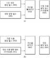
도 1은 본 발명이 적용되는 무선통신 시스템을 나타낸다.
도 2는 본 발명이 적용되는 무선 프레임의 구조를 나타낸다.
도 3은 본 발명이 적용되는 하나의 하향링크 슬롯에 대한 자원 그리드를 나타낸 예시도이다.
도 4는 본 발명이 적용되는 자원할당 방식의 일 예이다. 이는 타입0의 자원할당방식이다.
도 5는 본 발명이 적용되는 자원할당 방식의 다른 예이다. 이는 타입1의 자원할당방식이다.
도 6은 본 발명이 적용되는 자원할당 방식의 또 다른 예이다. 이는 타입2의 자원할당방식이다.
도 7은 본 발명에 따른 차동자원할당의 일 예를 나타내는 개념도이다
도 8은 본 발명에 따른 차동자원할당의 다른 예를 나타내는 개념도이다.
도 9는 본 발명에 따라서 차동자원할당의 또 다른 예를 나타내는 개념도이다.
도 10은 본 발명에 따라서 차동자원할당의 또 다른 예를 나타내는 개념도이다.
도 11은 본 발명에 따른 차동자원할당의 또 다른 예를 나타내는 도이다.
도 12는 본 발명에 따른 차동자원할당의 또 다른 예를 나타내는 도이다.
도 13은 본 발명에 따라서 차동자원할당방식과 관련된 기지국의 동작의 일 예를 나타내는 순서도이다.
도 14는 본 발명에 따라서 차동자원할당방식과 관련된 단말의 동작의 일 예를 나타내는 순서도이다.1 shows a wireless communication system to which the present invention is applied.
2 shows a structure of a radio frame to which the present invention is applied.
3 is a diagram illustrating an example of a resource grid for one downlink slot to which the present invention is applied.
4 is an example of a resource allocation scheme to which the present invention is applied. This is a
5 is another example of a resource allocation method to which the present invention is applied. This is a
6 is another example of a resource allocation scheme to which the present invention is applied. This is a
7 is a conceptual diagram illustrating an example of differential resource allocation according to the present invention
8 is a conceptual diagram showing another example of the differential resource allocation according to the present invention.
9 is a conceptual diagram showing another example of differential resource allocation according to the present invention.
10 is a conceptual diagram showing another example of differential resource allocation according to the present invention.
11 is a diagram illustrating another example of differential resource allocation according to the present invention.
12 is a diagram illustrating another example of differential resource allocation according to the present invention.
13 is a flowchart showing an example of the operation of the base station related to the differential resource allocation scheme according to the present invention.
FIG. 14 is a flowchart showing an example of the operation of a terminal related to a differential resource allocation scheme according to the present invention.
이하, 첨부된 도면을 참조하여 본 발명의 실시 예에 대하여 본 발명이 속하는 기술 분야에서 통상의 지식을 가진 자가 용이하게 실시할 수 있도록 상세히 설명한다. 그러나 본 발명은 여러 가지 상이한 형태로 구현될 수 있으며 이하에서 개시되는 실시 예에 한정되지 않는다. 또한 도면에서 본 발명을 명확하게 개시하기 위해서 본 발명과 관계없는 부분은 생략하였으며, 도면에서 동일하거나 유사한 부호들은 동일하거나 유사한 구성요소들을 나타낸다.Hereinafter, exemplary embodiments of the present invention will be described in detail with reference to the accompanying drawings so that those skilled in the art can easily carry out the present invention. The present invention may, however, be embodied in many different forms and should not be construed as limited to the embodiments set forth herein. Also, in order to clearly illustrate the present invention in the drawings, portions not related to the present invention are omitted, and the same or similar reference numerals denote the same or similar components.
본 발명의 실시예들에 따르면, '채널을 전송한다'라는 의미는 특정 채널을 통해 정보가 전송되는 의미로 해석될 수 있다. 여기서, 채널은 제어 채널과 데이터 채널을 모두 포함하는 개념이며, 제어 채널은 일례로 물리 하향링크 제어채널(Physical Downlink Control Channel: PDCCH) 혹은 물리 상향링크 제어채널(Physical Uplink Control Channel: PUCCH)이 될 수 있고, 데이터 채널은 일례로 물리 하향링크 공용채널(Physical Downlink Shared CHannel: PDSCH) 혹은 물리 상향링크 공용채널(Physical Uplink Shared CHannel: PUSCH)이 될 수 있다.According to embodiments of the present invention, 'transmitting a channel' can be interpreted as meaning that information is transmitted through a specific channel. Here, the channel includes both a control channel and a data channel, and the control channel may be a physical downlink control channel (PDCCH) or a physical uplink control channel (PUCCH), for example. And the data channel may be a Physical Downlink Shared CHannel (PDSCH) or a Physical Uplink Shared CHannel (PUSCH), for example.
도 1은 본 발명이 적용되는 무선통신 시스템을 나타낸다.1 shows a wireless communication system to which the present invention is applied.
도 1을 참조하면, 무선통신 시스템(10)은 음성, 패킷 데이터 등과 같은 다양한 통신 서비스를 제공하기 위해 널리 배치된다. 무선통신 시스템(10)은 적어도 하나의 기지국(11; evolved NodeB, eNB)을 포함한다. 각 기지국(11)은 특정한 지리적 영역 또는 주파수 영역(일반적으로 셀(cell)이라고 함)(15a, 15b, 15c)에 대해 통신 서비스를 제공한다. 셀은 다시 다수의 영역(섹터라고 함)으로 나누어질 수 있다.Referring to FIG. 1, a
단말(12; user equipment, UE)은 고정되거나 이동성을 가질 수 있으며, MS(mobile station), MT(mobile terminal), UT(user terminal), SS(subscriber station), 무선기기(wireless device), PDA(personal digital assistant), 무선 모뎀(wireless modem), 휴대기기(handheld device) 등 다른 용어로 불릴 수 있다.A user equipment (UE) 12 may be fixed or mobile and may be a mobile station (MS), a mobile terminal (MT), a user terminal (UT), a subscriber station (SS), a wireless device, (personal digital assistant), a wireless modem, a handheld device, and the like.
기지국(11)은 일반적으로 단말(12)과 통신하는 고정된 지점(fixed station)을 말하며, BS(Base Station), BTS(Base Transceiver System), 액세스 포인트(Access Point), 펨토 기지국(femto eNB), 가내 기지국(Home eNB: HeNB), 릴레이(relay), 원격 무선 헤드(Remote Radio Head: RRH)등 다른 용어로 불릴 수 있다. 셀은 기지국(11)이 커버하는 일부 영역을 나타내는 포괄적인 의미로 해석되어야 하며, 메가셀, 매크로셀, 마이크로셀, 피코셀, 펨토셀 등 다양한 커버리지 영역을 모두 포괄하는 의미이다.The
이하에서 하향링크(downlink)는 기지국(11)에서 단말(12)로의 통신 또는 통신 경로를 의미하며, 상향링크(uplink)는 단말(12)에서 기지국(11)으로의 통신 또는 통신 경로를 의미한다. 하향링크에서 송신기는 기지국(11)의 일부분일 수 있고, 수신기는 단말(12)의 일부분일 수 있다. 상향링크에서 송신기는 단말(12)의 일부분일 수 있고, 수신기는 기지국(11)의 일부분일 수 있다. 무선통신 시스템(10)에 적용되는 다중 접속 기법에는 제한이 없다. CDMA(Code Division Multiple Access), TDMA(Time Division Multiple Access), FDMA(Frequency Division Multiple Access), OFDMA(Orthogonal Frequency Division Multiple Access), SC-FDMA(Single Carrier-FDMA), OFDM-FDMA, OFDM-TDMA, OFDM-CDMA와 같은 다양한 다중 접속 기법을 사용할 수 있다. 상향링크 전송 및 하향링크 전송은 서로 다른 시간을 사용하여 전송되는 TDD(Time Division Duplex) 방식 또는 서로 다른 주파수를 사용하여 전송되는 FDD(Frequency Division Duplex) 방식이 사용될 수 있다.Hereinafter, a downlink refers to a communication or communication path from the
도 2는 본 발명이 적용되는 무선 프레임의 구조를 나타낸다.2 shows a structure of a radio frame to which the present invention is applied.
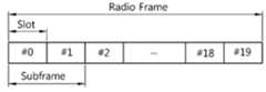
도 2를 참조하면, 무선 프레임(radio frame)은 10개의 서브프레임(subframe)을 포함하고, 하나의 서브프레임은 2개의 슬롯(slot)을 포함한다. 하나의 서브 프레임이 전송되는 데 걸리는 시간을 TTI(transmission time interval)이라 한다. 예를 들어 하나의 서브프레임의 길이는 1ms이고, 하나의 슬롯의 길이는 0.5ms 일 수 있다.Referring to FIG. 2, a radio frame includes 10 subframes, and one subframe includes 2 slots. The time taken for one subframe to be transmitted is called a transmission time interval (TTI). For example, the length of one subframe may be 1 ms and the length of one slot may be 0.5 ms.
하나의 슬롯은 시간 영역(time domain)에서 복수의 OFDM(orthogonal frequency division multiplexing) 심벌을 포함하고, 주파수 영역에서 다수의 자원 블록(resource block: RB)을 포함한다. OFDM 심벌은 하나의 심벌 구간(symbol period)을 표현하기 위한 것으로, 다중 접속 방식에 따라 SC-FDMA 심벌 또는 심벌 구간이라고 할 수 있다.One slot includes a plurality of orthogonal frequency division multiplexing (OFDM) symbols in a time domain and a plurality of resource blocks (RBs) in a frequency domain. An OFDM symbol represents one symbol period and may be referred to as an SC-FDMA symbol or a symbol interval according to a multiple access scheme.
하향링크에서, 서브프레임 내의 앞선 1 내지 3개의 OFDM 심벌들이 PDCCH가 맵핑되는 제어영역(control region)으로 사용되고, 서브프레임 내의 나머지 OFDM 심벌들은 PDSCH가 맵핑되는 데이터영역(data region)으로 사용된다. 제어영역에는 PDCCH 이외에도 PCFICH(Physical Control Format Indicator CHannel)가 할당될 수 있다. PCFICH는 서브프레임의 첫번째 OFDM 심벌에서 전송되고, 서브프레임내에서 제어영역으로 사용되는 OFDM 심벌의 수(즉, 제어영역의 크기)에 관한 정보를 나른다. 제어영역은 다중 사용자 MIMO(Multi User-MIMO: MU-MIMO), 연계된 다중점 방식(Coordinated Multiple Point: CoMP), 반송파 집성(Carrier Aggregation: CA)등과 같은 통신방식을 뒷받침하는데 필요한 제어정보를 지원하기에는 부족하다.In the downlink, the first to third OFDM symbols in the subframe are used as a control region to which the PDCCH is mapped, and the remaining OFDM symbols in the subframe are used as a data region to which the PDSCH is mapped. A PCFICH (Physical Control Format Indicator CHannel) may be allocated to the control area in addition to the PDCCH. The PCFICH is transmitted in the first OFDM symbol of the subframe and carries information on the number of OFDM symbols used as the control domain in the subframe (i.e., the size of the control domain). The control region supports control information necessary to support communication methods such as multi-user MIMO (MIMO), Coordinated Multiple Point (CoMP), and Carrier Aggregation (CA) It is not enough to do.
도 3은 본 발명이 적용되는 하나의 하향링크 슬롯에 대한 자원 그리드(resource grid)를 나타낸 예시도이다.3 is a diagram illustrating a resource grid for one downlink slot to which the present invention is applied.
도 3을 참조하면, 하향링크로 전송되는 PDCCH 또는 ePDCCH(enhanced PDCCH)을 통하여 상향/하향 통신을 위한 제어정보 및 주파수/시간 자원에서 각 단말에게 할당되는 자원할당정보를 전달한다.Referring to FIG. 3, control information for uplink / downlink communication and resource allocation information allocated to each UE in a frequency / time resource are transmitted through a PDCCH or an enhanced PDCCH (ePDCCH) transmitted in the downlink.
자원 영역은 자원블록(Resource Block:RB)의 시간 및 주파수 단위로 구성된다. 주파수 대역이 광대역인 경우 자원블록의 개수가 많아 자원할당정보를 나타내기 위한 비트요구량이 커지면, 복수의 자원블록으로 구성된 자원블록그룹(Resource Block Group: RBG)으로 처리한다.The resource area is composed of time and frequency units of a resource block (RB). When the frequency band is a wide band, if the number of resource blocks is large and the bit requirement amount for indicating the resource allocation information becomes large, the resource block group is composed of a plurality of resource blocks (RBG).
자원블록 또는 자원블록그룹으로 표현되는 자원할당정보는 PDCCH(또는 ePDCCH) 내의 자원할당필드(Resource Allocation Field)내의 RIV(Resource Indication Value) 형태로 전송된다.Resource allocation information represented by a resource block or a resource block group is transmitted in the form of RIV (Resource Indication Value) in a Resource Allocation Field in the PDCCH (or ePDCCH).
자원 그리드 상의 각 요소(element)를 자원요소(resource element: RE)라 하며, 하나의 자원블록은 12*7개의 자원요소를 포함한다. 하향링크 슬롯에 포함되는 자원블록의 수 NDLRB은 셀에서 설정되는 하향링크 전송 대역폭에 종속한다.Each element on the resource grid is called a resource element (RE), and one resource block includes 12 * 7 resource elements. The number of resource blocks NDLRB included in the downlink slot is dependent on the downlink transmission bandwidth set in the cell.
LTE에서 고려되는 대역폭은 1.4MHz, 3MHz, 5MHz, 10MHz, 15MHz, 20MHz이고 이를 자원블록의 개수로 표현하면 각각 6, 15, 25, 50, 75, 100이다. 각 대역에 해당하는 적어도 하나 이상의 자원블록이 묶여서 자원블록그룹(Resource Block Group; RBG)을 구성할 수 있다. 예를 들어, 인접한 2개의 자원블록이 하나의 자원블록그룹을 구성할 수 있다.The bandwidths considered in LTE are 1.4 MHz, 3 MHz, 5 MHz, 10 MHz, 15 MHz, and 20 MHz, which are expressed as 6, 15, 25, 50, At least one resource block corresponding to each band may be bundled to form a resource block group (RBG). For example, two adjacent resource blocks may constitute one resource block group.
각 대역폭별 총 자원블록의 개수 및 하나의 자원블록그룹을 구성하는 자원블록의 개수의 일 예는 표 1과 같다.Table 1 shows an example of the total number of resource blocks for each bandwidth and the number of resource blocks constituting one resource block group.
표 1을 참조하면, 주어진 대역폭에 따라 사용 가능한 총 자원블록의 개수가 다르다. 총 자원블록의 개수가 다르다는 것은 자원할당을 지시하는 정보의 크기가 달라짐을 의미한다.Referring to Table 1, the number of available resource blocks is different according to a given bandwidth. The difference in the total number of resource blocks means that the size of the information indicating resource allocation varies.
자원블록을 할당하는 경우의 수는 자원할당 방식(타입0 내지 타입2)에 따라 다를 수 있다.The number of resource block allocations may be different depending on the resource allocation scheme (
자원할당 방식의 일 예로서, 자원블록은 비트맵 형식을 이용하여 할당될 수 있다(타입0).As an example of a resource allocation scheme, a resource block may be allocated using a bitmap format (type 0).
자원할당 방식의 다른 예로서, 자원블록은 소정의 간격 또는 주기로 할당될 수 있다(타입1).As another example of the resource allocation scheme, resource blocks may be allocated at predetermined intervals or periods (type 1).
자원할당 방식의 또 다른 예로서, 자원블록은 연속된 일정 길이의 영역으로서 할당될 수 있다(타입2).As another example of the resource allocation scheme, a resource block can be allocated as an area of a continuous constant length (type 2).
자원할당정보에 의해 단말에 할당되는 자원블록이 지시되며, 자원할당정보의 비트요구량은 각 자원할당 방식 또는 대역폭 별 총 자원블록의 개수에 따라 다르다.A resource block allocated to the mobile station is indicated by the resource allocation information, and the bit request amount of the resource allocation information is different according to the number of total resource blocks for each resource allocation scheme or bandwidth.
도 4는 본 발명이 적용되는 자원할당 방식의 일 예이다. 이는 타입0의 자원할당방식이다.4 is an example of a resource allocation scheme to which the present invention is applied. This is a
타입 0의 자원할당방식은 시스템의 전체 자원블록에 대해 적어도 하나의 연속적인 자원블록으로 묶인 클러스터(cluster) 단위로 단말에 할당하는 방식이다. 클러스터 간에는 적어도 하나의 자원블록만큼 이격되면, 이를 불연속적 자원할당(Non-contiguous Resource Allocation)이라고도 한다. 클러스터가 1개인 경우 이는 연속적 자원할당(Contiguous Resource Allocation)이라 하며 타입 0은 연속적 자원할당도 포함한다. 특히, 하향링크 타입 2는 연속적 자원할당만을 나타내는 경우로 고려된다.A resource allocation scheme of
도 4를 참조하면, 총 4개의 클러스터가 단말에 할당된다. 1번째 클러스터(405)는 1개의 자원블록, 2번째 클러스터(410)는 3개의 자원블록, 3번째 클러스터(415)는 2개의 자원블록, 4번째 클러스터(420)는 1개의 자원블록을 각각 포함한다. 몇 개의 클러스터를 할당가능한지에 따라 시스템의 수율(throughput)이 달라질 수 있다.Referring to FIG. 4, a total of four clusters are allocated to the UE. The
상기 타입 0, 타입 1 및 타입 2는 하향링크 자원할당에 해당한다.The
상향링크 자원할당은 상향링크에 대한 타입 0, 타입 1로 구분될 수 있다. 이 중 상향링크 타입 0는 하향링크 타입 2와 같은 방식이 사용될 수 있다. 반면, 상향링크 타입 1은 열거원천부호화 방식으로 제한된 클러스터를 사용하며, 일 예로 두 개의 클러스터로 한정하는 방식이 있다.The uplink resource allocation can be classified into
각 자원블록의 할당 또는 비할당은 비트맵으로 표현될 수 있다. 각 비트는 각 자원블록에 맵핑된다. 예를 들어, 비트 값이 0이면 해당 자원블록이 단말에 할당되는 것이고, 비트 값이 1이면 해당 자원블록이 단말에 할당되지 않는 것이다.The assignment or unassignment of each resource block can be represented by a bitmap. Each bit is mapped to each resource block. For example, if the bit value is 0, the corresponding resource block is allocated to the terminal, and if the bit value is 1, the corresponding resource block is not allocated to the terminal.
상기 도 4에서, 비트맵은 "010011100110100"이다.In Fig. 4, the bitmap is "010011100110100 ".
타입 0과 같이 비트맵 형식으로 단말에 대한 자원할당을 하는 경우, 비트요구량은 자원블록의 개수와 같다. 즉, 자원블록의 개수가 n이고 하나의 자원블록그룹을 구성하는 자원블록의 개수가 p일 때, 요구비트양은 "
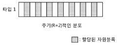
도 5는 본 발명이 적용되는 자원할당 방식의 다른 예이다. 이는 타입1의 간단한 자원할당방식의 예이다.5 is another example of a resource allocation method to which the present invention is applied. This is an example of a simple resource allocation scheme of
타입1 자원할당에서, 자원블록은 소정의 주기(R)를 가지고 할당되며 전체 자원블록에 대해 일정한 간격으로 분포하는 형식으로 표현된다.In a
도 5를 참조하면, 주기(R)는 "2"인 경우이다.Referring to Fig. 5, the period R is "2 ".
타입1의 자원할당방식을 표현하기 위한 요구비트양은 타입0 의 경우와 같으며 비트맵형태의 요구량은 "

한편, 타입 0와 타입 1이 함께 사용될 경우, 타입 0와 타입 1을 구분하기 위한 구분 비트(differentiation bit)가 추가될 수 있다.On the other hand, when
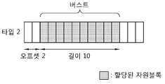
도 6은 본 발명이 적용되는 자원할당 방식의 또 다른 예이다. 이는 타입2의 자원할당방식이다. 타입2의 자원할당방식은 자원블록의 형태로 표현이 가능하다.6 is another example of a resource allocation scheme to which the present invention is applied. This is a
도 6을 참조하면, 기지국은 연속적인 적어도 하나의 자원블록으로 구성되는 클러스터를 단말에 할당할 수 있다. 하나의 클러스터는 전체 자원블록의 시작점에서의 오프셋, 길이(length)로 표현된다. 상기 도 6의 클러스터는 오프셋이 2이고 길이가 10이므로, 3번째 자원블록부터 연속적인 10개의 자원블록들을 포함한다.Referring to FIG. 6, a base station can allocate a cluster to a terminal, which is composed of at least one continuous resource block. One cluster is represented by an offset, length, at the start of the entire resource block. Since the cluster of FIG. 6 has an offset of 2 and a length of 10, the resource block includes 10 consecutive resource blocks starting from the third resource block.
타입 0과 타입 1이 불연속적 자원할당을 나타내는데 반하여, 타입 2는 연속적 자원할당을 나타낸다. 따라서 자원블록의 개수가 많은 경우 타입 2의 자원할당을 표현하는데 필요한 자원할당정보의 비트수는 타입 0 또는 타입 1에 비해 작다.While
또 다른 예로, 하향 타입 2(또는 상향 타입0)가 하나의 연속된 블록에 의해 나타내는 자원할당만을 나타내며 불연속적인 다수의 블록에 의한 상향링크 자원할당이 고려될 수도 있다. 즉, 불연속 자원할당이 고려될 수 있다.As another example, downlink type 2 (or uplink type 0) may represent only resource allocation represented by one continuous block, and uplink resource allocation by a plurality of discontinuous blocks may be considered. That is, discontinuous resource allocation can be considered.
타입 2 자원할당 방식으로 n개의 자원블록을 할당하는 경우, 자원할당의 모든 경우의 수(n+1C2)는 다음 수학식 1과 같다.In the case of allocating n resource blocks by the

이때, 자원할당정보의 요구비트양은 다음 수학식 2와 같다.At this time, the requested bit amount of the resource allocation information is expressed by

하향 타입2의 RIV의 일 예는 다음 수학식과 같다.One example of the RIV of the

LCRBs는 1보다 크거나 같고 "NDLRB- RBstart"를 넘지 않는 것을 조건으로 한다.LCRBs is greater than or equal to 1 and "NDLRB - RBstart ".
여기서, RBstart는 시작 자원블록을 나타내고, LCRBs는 연속자원할당의 길이(예, 자원블록 단위 또는 자원블록그룹 단위)를 나타내고, NDLRB는 하향링크의 자원블록의 개수를 나타낸다.Here, RBstart represents a starting resource block, LCRBs represents a length of a continuous resource allocation (e.g., resource block unit or resource block group unit), and NDLRB represents the number of downlink resource blocks.
한편, 3GPP LTE Release-8/9에서는 상향링크의 물리상향공유채널(Physical Uplink Shared Channel:PUSCH)의 자원할당에 대하여 하향 타입 2 자원할당 방식을 적용하되 상기 수학식 3에서 NDLRB가 NULRB로 바뀐 형태이다. 이는 상향 타입 0 자원할당 방식이다.In 3GPP LTE Release-8/9, a
기존의 3GPP LTE Release-8/9에서 상향 타입 0 자원할당 방식이 하나의 연속된 블록에 의해 나타나는 자원할당과 달리, 불연속적인 복수의 블록에 의한 상향링크 자원할당(즉, 불연속 자원할당)하는 방식이 제안된다.Unlike the resource allocation in which the
일 예로, 불연속 자원할당은 하향 타입 0이 고려되는 자원할당이 주어진 자원블록그룹의 전체 범위에서 가능한 모든 불연속 할당을 가능하게 하되, 제한된 개수의 클러스터(예, 2개)만 고려된다.In one example, a discrete resource allocation allows all possible discrete allocation in the entire range of resource block groups given the resource allocation for which
본 발명에 따르면, 제한된 개수의 클러스터를 사용하는 불연속 자원할당을 위한 RIV의 부호화/복호화를 위한 방안의 일 예로 열거원천부호화(enumerative source coding)가 있다.According to the present invention, enumerative source coding is an example of a method for coding / decoding RIV for discontinuous resource allocation using a limited number of clusters.
열거원천부호화는 채널품질지시자(Channel Quality Indicator)를 나타내는 방안으로도 사용되며, 표준화의 용이하고 기존 구현된 시스템의 확장의 효과가 있어 복잡도감소와 구현안정성 보장의 장점이 있다.The enumerative source coding is also used as a method of indicating a channel quality indicator, and it has advantages of simplification of standardization and expansion of existing implemented system, thereby reducing complexity and ensuring stability of implementation.
채널품질지시자에 대한 열거원천부호화는 서브밴드(subband) 단위로 이루어지며, 주어진 서브밴드 영역 내(예, 1 내지 N)에서 소정의 개수(M)의 서브밴드를 선택함을 표현한다.The enumerated source coding for the channel quality indicator is performed on a subband basis and represents the selection of a predetermined number (M) of subbands within a given subband region (e.g., 1 to N).
열거원천부호화의 일 예는 다음 수학식과 같다. 오름차순 크기로 정렬된 M개의 서브밴드 인덱스(

여기서

열거원천복호화의 일 예는 다음 표 2와 같다.An example of enumerative decryption is shown in Table 2 below.


본 발명에 따르면, 열거원천부호화를 적용하여 상향링크의 자원할당을 할 수 있다. 이와 같은 자원할당방식은 상향 타입1이다.According to the present invention, uplink resource allocation can be performed by applying enumerative source coding. This type of resource allocation is
일 예로, 두 개의 클러스터 단위를 기반으로 구성하고 각 클러스터의 시작점 및 끝점의 쌍을 {s0, s1-1, s2, s3-1}로 표현하여 상기 수학식 4의 r값을 RIV값으로 결정할 수 있다. 여기서, s0는 첫번째 클러스터의 시작점, s1-1는 첫번째 클러스터의 끝점, s2는 두번째 클러스터의 시작점, s3-1는 두 번째 클러스터의 끝점을 나타낸다. 이때, "M=4"이며 "

한편, 상향링크의 자원할당을 위한 RIV 값은 상향링크 그랜트의 자원할당필드(Resource Allocation Field)에 포함될 수 있다.Meanwhile, the RIV value for uplink resource allocation may be included in the resource allocation field of the UL grant.
PDCCH에 맵핑되는 물리계층의 제어정보를 하향링크 제어정보(downlink control information;DCI)라고 한다. 즉, DCI는 PDCCH상으로 전송된다. DCI는 그 포맷(format)에 따라 사용용도가 다르고, DCI내에서 정의되는 필드(field)도 다르다. 다음 표는 DCI 포맷에 따른 DCI를 나타낸다.Control information of the physical layer mapped to the PDCCH is referred to as downlink control information (DCI). That is, the DCI is transmitted on the PDCCH. The DCI has different uses according to its format, and the fields defined in the DCI are different. The following table shows the DCI according to the DCI format.
표 3를 참조하면, DCI 포맷 0은 상향링크 자원 할당 정보를 가리키고, DCI 포맷 1,2는 하향링크 자원 할당 정보를 가리키며, DCI 포맷 3, 3A는 임의의 단말 그룹들에 대한 상향링크 전송전력제어(transmit power control: TPC) 명령을 가리킨다. DCI의 각 필드는 n개의 정보비트(information bit) a0 내지 an-1에 순차적으로 맵핑된다. 예를 들어, DCI가 총 44비트 길이의 정보비트에 맵핑된다고 하면, DCI 각 필드가 순차적으로 a0 내지 an-1에 맵핑된다. DCI 포맷 0, 1A, 3, 3A는 모두 동일한 페이로드(payload) 크기를 가질 수 있다. DCI 포맷 0은 상향링크 그랜트(uplink grant)라 불릴 수도 있다. DCI 포맷 2C는 단일 셀(cell) 또는 단일 링크(link)에 대한 다중 레이어 전송 제어를 위해 사용된다. 즉, DCI 포맷 2C는 단일 셀 공간 다중화(Single cell spatial multiplexing) 모드에서 사용되는 DCI 포맷이다. 단일 셀 공간 다중화는 동시에 여러 데이터 스트림(data stream)의 전송을 지원한다.Referring to Table 3,
상향링크 그랜트 중 DCI 포맷 0의 자원할당필드는 연속자원할당만 고려한다. 자원할당필드의 비트요구량의 증가에 의해 DCI 포맷 0의 크기가 증가하지 않는 것이 바람직하다. 왜냐하면, DCI 포맷 0의 크기가 증가함에 따라 블라인드 복호의 증가를 초래하거나 기존 규격과 호환성에 문제를 야기할 수 있기 때문이다.The
따라서, 본 발명에 따르면, 클러스터의 크기를 2개로 제한하고 DCI 포맷 0에서 사용하지 않는 잉여 비트 1비트를 연속/불연속을 구분하는 비트로 사용하고, 불연속자원할당의 경우 주파수 호핑(Frequency Hopping)여부를 나타내는 비트를 불연속자원할당의 자원할당의 추가여분비트로 사용할 수 있다. 이때, DCI 포맷 0는 LTE에서 고려하고 있는 대부분의 대역에서 기존의 크기를 그대로 유지하며 불연속자원할당의 기능을 가능하게 할 수 있다.Therefore, according to the present invention, the size of the cluster is limited to two, one bit of the redundant bit that is not used in the
이제, 본 발명에 따라서 채널 특성을 고려한 PDCCH 또는 ePDCCH의 자원할당필드의 압축 방법 및 장치를 제안한다.Now, a method and apparatus for compressing a resource allocation field of a PDCCH or an ePDCCH considering a channel characteristic according to the present invention is proposed.
기지국은 특정 단말에게(UE specific) 상위계층시그널링(예, RRC 시그널링)을 전송함으로써 차동자원할당을 구성(configure)한다. 즉, 상위계층시그널링에 의해 차동자원할당방식의 사용여부가 결정된다.The base station configures differential resource allocation by transmitting (UE specific) upper layer signaling (e.g., RRC signaling) to a particular terminal. That is, the use of the differential resource allocation scheme is determined by the upper layer signaling.
기준자원할당필드는 차동자원할당필드를 구성하기 위해 기준이 되는 자원할당필드이고, 현 자원할당필드 이전에 할당된 자원할당필드중의 하나이며, 상향 및 하향의 모든 타입이 가능하다.The reference resource allocation field is a reference resource allocation field for configuring the differential resource allocation field, and is one of the resource allocation fields allocated before the current resource allocation field, and all types of uplink and downlink are possible.
기준자원할당필드가 단말에게 알려지는 방식의 예는 다음과 같다.An example of how the reference resource allocation field is known to the UE is as follows.
첫번째 방식으로, 기준자원할당필드는 상위계층시그널링(예, RRC 시그널링)에 의해 특정 단말에게 알려질 수 있다. 이는 상위계층시그널링에 의해 차동자원할당필드가 구성될 때와 동일하다.In the first method, the reference resource allocation field can be informed to a specific terminal by higher layer signaling (e.g., RRC signaling). This is the same as when the differential resource allocation field is configured by higher layer signaling.
두번째 방식으로, 기준자원할당필드는 현 자원할당필드가 속한 PDCCH(또는 ePDCCH)에 의해 자원할당되는 PDSCH 또는 PUSCH를 포함하는 서브프레임 바로 이전에(예, 하나 또는 복수의 서브프레임 이전) 스케줄링된 PDSCH 또는 PUSCH에 대하여 자원할당하는 PDCCH(또는 Epdcch)가 포함하는 자원할당필드로 알려질 수 있다. 일 예로, 크로스 캐리어 스케줄링(cross carrier scheduling)의 경우 CIF(Carrier Indicator Field)가 동일한 경우의 PDCCH(또는 ePDCCH)에서만 차동자원할당방식이 고려된다. 또는, 소정의 주기를 단위로 구성될 수 있다. 이는 각 주기의 첫번째 PDSCH 또는 PUSCH를 할당하는 PDCCH(또는 ePDCCH)의 자원할당필드는 차동자원할당필드와 연계 없이 구성됨을 의미한다.In the second scheme, the reference resource allocation field is allocated to the scheduled PDSCH (or one or more subframes) immediately before the subframe containing the PDSCH or PUSCH to which the current resource allocation field belongs by the PDCCH (or ePDCCH) Or a PDCCH (or Epdcch) allocating a resource for the PUSCH. For example, in the case of cross carrier scheduling, a differential resource allocation scheme is considered only in the PDCCH (or ePDCCH) when the Carrier Indicator Field (CIF) is the same. Alternatively, it may be configured in units of a predetermined period. This means that the resource allocation field of the PDCCH (or ePDCCH) allocating the first PDSCH or PUSCH of each period is configured without being associated with the differential resource allocation field.
세번째 방식으로, 기준자원할당필드는 소정의 일정한 개수의 서브프레임을 주기로 하여 각 주기의 가장 먼저 스케줄링된 PDSCH 또는 PUSCH의 자원할당을 지시하는 자원할당필드로 단말에게 알려질 수 있다. 예를 들어, 하나의 프레임(예, 10개의 서브프레임)을 주기로 하여, 매 프레임마다 가장 먼저 스케줄링된 PDSCH 또는 PUSCH의 자원을 지시하는 자원할당필드가 기준자원할당필드일 수 있다. 만약 기준자원할당필드를 포함하는 PDCCH(또는 ePDCCH)의 복호에서 오류가 발생하면 상기 오류가 전파되어 나머지 PDCCH(또는 ePDCCH)에 의해 지시되는 PDSCH(또는 PUSCH)의 복호에서도 오류가 발생할 수 있다. 즉, 프레임 내 모든 서브프레임에 PDSCH가 할당되고 첫번째 서브프레임의 PDSCH의 자원을 나타내는 자원할당필드가 기준자원할당필드가 되고 상기 기준자원할당필드를 포함하는 PDCCH의 복호에서 오류가 발생한다면, 나머지 서브프레임들에 대한 PDSCH의 복호에서 오류가 발생한다. 이러한 오류 전파를 방지하지는 방법의 일 예로, 기준자원할당필드를 포함하는 PDCCH(또는 ePDCCH)의 집성레벨(Aggregation level)을 높혀서 전송하는 방법이 있다. 집성레벨을 높이면 PDCCH(또는 ePDCCH)의 복호오율성능이 향상된다. 이때, 집성레벨을 높이는 것은 LTE 규격에 따르면 기지국의 스케줄링에 의하여 가능하다.In the third scheme, the reference resource allocation field may be informed to the UE as a resource allocation field indicating a resource allocation of the first scheduled PDSCH or PUSCH of each cycle with a predetermined number of subframes as a period. For example, a resource allocation field indicating a resource of the PDSCH or PUSCH that is first scheduled for every frame may be a reference resource allocation field, with one frame (e.g., 10 subframes) as a period. If an error occurs in the decoding of the PDCCH (or ePDCCH) including the reference resource allocation field, the error is propagated and an error may occur in decoding of the PDSCH (or PUSCH) indicated by the remaining PDCCH (or ePDCCH). That is, if a PDSCH is allocated to all subframes in a frame, a resource allocation field indicating a PDSCH resource of a first subframe is a reference resource allocation field, and an error occurs in decoding of a PDCCH including the reference resource allocation field, An error occurs in the decoding of the PDSCH for the frames. As an example of a method for preventing such error propagation, there is a method of increasing the aggregation level of the PDCCH (or ePDCCH) including the reference resource allocation field. Increasing the aggregation level improves the decoding performance of PDCCH (or ePDCCH). At this time, it is possible to increase the aggregation level by scheduling the base station according to the LTE standard.
네번째 방식으로, 기준자원할당필드는 소정의 일정한 개수의 서브프레임을 주기로 하여 각 주기 내 특정 서브프레임(예, 처음 복호되어 검출되는 서브프레임)에 존재하는 PDCCH(또는 ePDCCH)에 포함되는 자원할당필드로 단말에게 알려지거나, 특정 서브프레임(예, 처음 복호되어 검출되는 서브프레임)에 존재하는 PDSCH 또는 PUSCH를 스케줄링하는 PDCCH(또는 ePDCCH)에 포함되는 자원할당필드로 단말에게 알려질 수 있다. 일 예로, 상기 특정 서브프레임은 주기가 복수의 서브프레임 일 때 각 주기의 첫번째 서브프레임일 수 있다. 또는, 각 단말은 동일한 주기를 가지되 서로 다른 서브프레임 오프셋을 가질 수 있다. In a fourth scheme, the reference resource allocation field includes a resource allocation field (PDCCH) included in a PDCCH (or ePDCCH) existing in a specific subframe (e.g., a first decoded and detected subframe) in each cycle with a predetermined number of subframes as a period, Or a resource allocation field included in a PDCCH (or ePDCCH) scheduling a PDSCH or a PUSCH existing in a specific subframe (e.g., a subframe that is first detected and detected). For example, the specific subframe may be the first subframe of each period when the period is a plurality of subframes. Alternatively, each terminal may have the same period and have different sub-frame offsets.
한편, 차동자원할당의 구성 이후, 단말은 PDCCH(또는 ePDCCH)의 복호에 있어 차동자원할당방식을 가정하고, 차동자원할당방식에 따라 변경되는 PDCCH(또는 ePDCCH)의 크기를 기초로 블라인드 복호를 수행한다. 차동자원할당방식은 기지국의 상위계층시그널링에 의해 해제(release)될 수 있다.On the other hand, after the configuration of the differential resource allocation, the UE assumes a differential resource allocation scheme for decoding the PDCCH (or ePDCCH) and performs blind decoding based on the size of the PDCCH (or ePDCCH) changed according to the differential resource allocation scheme do. The differential resource allocation scheme may be released by upper layer signaling of the base station.
이하에서, "하향 타입2, 상향 타입0, 상향 타입1"에 대한 경우와, "하향 타입 0, 하향 타입1"에 대한 경우로 나누어 설명한다.Hereinafter, the case of "down
<1. 하향 타입2, 상향 타입0, 상향 타입1><1. Down
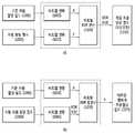
도 7은 본 발명에 따른 차동자원할당의 일 예를 나타내는 개념도이다. 이하에서, 차동(differential)은 차이값을 말한다.7 is a conceptual diagram illustrating an example of differential resource allocation according to the present invention. In the following, the differential refers to the difference value.
도 7을 참조하면, (a)는 부호기의 동작을 나타낸다.Referring to FIG. 7, (a) shows the operation of the encoder.
기준자원할당필드(700)와 자원할당필드(705)의 차동연산(710)을 통해 차동자원할당필드를 구성한다(715).A differential resource allocation field is configured through a
차동자원할당필드(715)는 현재 서브프레임 중 기지국이 스케줄링한 PDCCH(또는 ePDCCH)의 일부 영역인 자원할당필드이며, 기지국이 특정 단말에게 할당하는 PUSCH 또는 PDSCH의 자원할당정보를 나타내는 필드이다.The differential resource allocation field 715 is a resource allocation field, which is a partial region of the PDCCH (or ePDCCH) scheduled by the BS in the current subframe, and is a field indicating PUSCH or PDSCH resource allocation information that the BS allocates to a specific MS.
자원할당필드(705)는 상향 및 하향의 모든 타입 형태가 가능하다.The
한편, 차동자원할당방식의 수행 여부는 기지국에서 단말로 암시적으로(implicitly) 시그널링 될 수 있다. 예를 들어, 특정 서브프레임(예, 첫번째 서브프레임)에서 기준자원할당필드 길이에 해당하는 PDCCH(또는 ePDCCH)가 복호되어 기준자원할당필드의 존재가 확인되는 경우 해당 주기 전체에서 차동자원할당방식을 사용하고 기준자원할당필드 길이에 해당하는 PDCCH(또는 ePDCCH)가 복호되지 않아 기준자원할당필드의 존재가 확인되지 않는 경우 차동자원할당방식을 사용하지 않도록 기지국과 단말간에 설정될 수 있다. 기준자원할당필드의 크기와 차동자원할당필드의 크기가 서로 다른 경우뿐만 아니라 동일한 경우에도 적용될 수 있다.Meanwhile, whether or not the differential resource allocation scheme is performed can be implicitly signaled from the base station to the mobile station. For example, if the PDCCH (or ePDCCH) corresponding to the reference resource allocation field length is decoded in a specific subframe (e.g., the first subframe) and the existence of the reference resource allocation field is confirmed, the differential resource allocation scheme And the PDCCH (or ePDCCH) corresponding to the reference resource allocation field length is not decoded so that the existence of the reference resource allocation field is not confirmed, the differential resource allocation scheme can be set between the base station and the UEs. The present invention can be applied not only to the case where the size of the reference resource allocation field and the size of the differential resource allocation field are different but also to the same case.
한편, 차동연산(710)은 기준자원할당필드와 자원할당필드의 차이를 소정의 길이의 필드(즉, 차동자원할당필드)로 나타내는 연산을 말하며, 채널 특성이 시간에 따라 크게 변하지 않는 경우 기준자원할당필드와 자원할당필드의 차이가 크지 않아 차동연산 결과도 크지 않다. 기준자원할당필드의 비트길이가 x이고 자원할당필드의 비트길이가 y이고 차동자원할당필드의 비트길이가 z라면(단, z<x 또는 z<y), 차동연산의 결과는 다음 수학식과 같다.Meanwhile, the

여기서, X는 기준자원할당필드를 이진수형태로 나타낸 것이고, Y는 자원할당필드를 이진수형태로 나타낸 것이고, "Δ()"는 차동연산(예, "Δ(A,B)=A-B")을 나타내며, Δ(Y,X)는 결과적으로 차동자원할당필드가 된다.Here, X denotes a reference resource allocation field in binary form, Y denotes a resource allocation field in binary form, and "Δ () '' denotes a differential operation (eg," Δ (A, B) = AB " , And Δ (Y, X) results in a differential resource allocation field.
한편, 차동역연산(760)은 차동자원할당필드를 기초로 기준자원할당필드 또는 자원할당필드를 구하는 연산을 말하며, 차동역연산의 결과는 다음 수학식과 같다.On the other hand, the differential co-operation operation 760 refers to an operation for obtaining a reference resource allocation field or a resource allocation field based on a differential resource allocation field, and the result of the differential operation is as follows.

여기서, "Δ-1()" 는 차동역연산(예, "Δ-1(A,B)=A+B")을 의미한다.Here, "?-1 ()" means a differential operation (e.g.,?-1 (A, B) = A + B).
한편, 차동연산결과(즉, Δ(Y,X))는 음의 부호를 가질 수 있으며, 음의 부호를 갖는 차동연산결과는 이진 형태(예, 1의 보수 또는 2의 보수)로 표현될 수 있다.On the other hand, the differential operation result (i.e.,? (Y, X)) may have a negative sign, and the differential operation result having a negative sign may be expressed in binary form (e.g., 1's complement or 2's complement) have.
한편, 상기 도 7의 (b)는 복호기의 동작을 나타낸다. 복호 과정은 부호 과정의 역과정일 수 있다. 즉, 기준자원할당필드(750)와 차동자원할당필드(755)의 역차동연산(760)을 통해 자원할당필드(765)가 구성될 수 있다.7 (b) shows the operation of the decoder. The decoding process can be the inverse of the coding process. That is, the resource allocation field 765 may be configured through the inverse differential operation 760 of the reference
도 8은 본 발명에 따른 차동자원할당의 다른 예를 나타내는 개념도이다. 하향 타입2 또는 상향 타입0,1에 해당하는 예이다. 제1 방법에 대한 설명이다.8 is a conceptual diagram showing another example of the differential resource allocation according to the present invention. Down
도 8을 참조하면, (a)는 부호기의 동작을 나타낸다. 기준자원할당필드(800) 및 자원할당필드(805)를 뺄셈연산(810)하여 차동자원할당필드(815)를 구성한다. 일 예로, 상기 차동자원할당필드는 이진수로 표현될 수 있다.Referring to FIG. 8, (a) shows the operation of the encoder. The
(b)는 복호기의 동작을 나타낸다. 기준자원할당필드(850) 및 이진수로 표현된 차동자원할당필드(855)를 합연산(860)하여 자원할당필드(865)를 구성한다.(b) shows the operation of the decoder. (860) a reference resource allocation field 850 and a differential resource allocation field 855 represented by a binary number to configure a
도 9는 본 발명에 따라서 차동자원할당의 또 다른 예를 나타내는 개념도이다. 하향 타입2 또는 상향 타입0,1에 해당하는 예이다. 제2 방법에 대한 설명이다.9 is a conceptual diagram showing another example of differential resource allocation according to the present invention. Down
도 9를 참조하면, (a)는 부호기의 동작을 나타낸다. 기준자원할당필드(900) 및 자원할당필드(905)를 계수별로 뺄셈연산(910)하여 차동자원할당필드(915)를 구성한다. 일 예로, 상기 차동자원할당필드는 이진수로 표현될 수 있다.Referring to FIG. 9, (a) shows the operation of the encoder. The reference resource allocation field 900 and the
(b)는 복호기의 동작을 나타낸다. 기준자원할당필드(950) 및 이진수로 표현된 차동자원할당필드(955)를 계수별로 합연산(960)하여 자원할당필드(965)를 구성한다.(b) shows the operation of the decoder. A reference resource allocation field 950 and a differential resource allocation field 955 represented by a binary number are summed (960) on a coefficient basis to constitute a resource allocation field 965.
상기 도 8의 실시예는 전체 자원할당필드의 차이 값을 구하는 반면, 상기 도 9의 실시예는 자원할당 방식을 구성하는 계수의 차동값을 구하고 상기 차동값을 기초로 각 타입 별 자원할당구성공식에 따라서 자원할당필드를 구성함에 차이가 있다.The embodiment of FIG. 8 obtains the difference value of the entire resource allocation field, whereas the embodiment of FIG. 9 obtains the differential value of the coefficients constituting the resource allocation method, and based on the differential value, And the resource allocation field is configured according to the resource allocation field.
구체적으로 설명하면, 자원할당방식을 구성하는 각 계수들의 차동값을 구하고 이를 1의 보수 또는 2의 보수 형태로 표현한 후, 이를 양의 정수 이진수로 해석하여 자원할당필드를 구성할 수 있다. 일 예로, "n+1"비트 길이의 이진값에 대하여, 1의 보수형태는 "-2n+1 ~ 2n-1"의 범위를 가지고 2의 보수형태는 "-2n+1 ~ 2n"의 범위를 가진다.Specifically, a resource allocation field can be constructed by obtaining a differential value of each coefficient constituting the resource allocation scheme, expressing it as 1's complement or 2's complement, and interpreting it as a positive integer binary number. For example, for a binary value of "n + 1" bit length, the complement of 1 has a range of "-2n +1 to 2n -1" and the complement of 2 has a range of "-2n +1 to 2n " .< / RTI >
다른 예로, 1의 보수 또는 2의 보수형태로 양의 이진수로 판단해서 진행하는 방식이외에 일정값을 더해서 진행하는 방식이 있다. 즉, 음의 값을 가지는 "D"에 대해서 "D+일정값"으로 더해줘 "0" 또는 "자연수"로 표현하고 이 것을 이진수로 표현할 수 있다. 1의 보수 또는 2의 보수와 같은 조건을 가정한다면, 일 예로 상기 일정값은 "2n-1"일 수 있다.As another example, there is a method in which a certain value is added in addition to a method of judging a positive binary number as a 1's complement or a 2's complement type and proceeding. That is, "D +" having a negative value is added as "D + constant value" and expressed as "0" or "natural number", and this can be represented by a binary number. Assuming conditions such as 1's complement or 2's complement, the constant value may be "2n -1 ", for example.
하향 타입 2, 상향 타입 0의 경우 RIV는 다음 수학식과 같이 구성될 수 있다.For the

ΔLCRBs는 1보다 크거나 같고 "N'-RBstart"를 넘지 않는 것을 조건으로 한다. 여기서, ΔRBstart는 시작 자원블록을 차동값을 나타내고, ΔLCRBs는 연속자원할당의 길이(예, 자원블록 단위 또는 자원블록그룹 단위)의 차동값을 나타내고, N'는 기지국에 의해 주어진 한계값이다. N'를 기초로 "가능한 길이"와 "오프셋"의 범위가 구해진다.ΔLCRBs is greater than or equal to 1 and does not exceed "N'-RBstart ". Here, ΔRBstart denotes a differential value of the starting resource block, ΔLCRBs denotes a differential value of the length of consecutive resource allocation (eg, resource block unit or resource block group unit), and N 'is a threshold value given by the base station . The range of "possible length" and "offset" is determined based on N '.
반면, 상향타입 1의 경우 차동인덱스(Δsk)는 기준자원할당필드의 계수 Sr과 자원할당필드의 계수 Sc의 차이(즉, Δsk=sr-sc)로 정의된다.On the other hand, in the case of the up-
M개의 차동인덱스(


Δs'k 를 기초로 다음 수학식과 같이 r 값이 계산된다.Based on? S 'k , the r value is calculated as shown in the following equation.

여기서

한편, 하향 타입 2 또는 상향 타입 0에 대한 자원할당필드 구성을 위한 계수들은 기준자원할당필드 및 자원할당필드에 해당하는 LCRBs, RBstart이다. 여기서, RBstart는 시작 자원블록을 나타내고, LCRBs는 연속자원할당의 길이(예, 자원블록 단위 또는 자원블록그룹 단위)를 나타낸다.Meanwhile, the coefficients for the resource allocation field configuration for
이때, LCRBs, RBstart의 차동값 "ΔLCRBs=LcCRBs - LrCRBs", "ΔRBstart=RBcstart-RBrstart"을 구할 수 있다. 여기서, "c"첨자는 현 자원할당필드를 나타내고 "r"첨자는 기준자원할당필드를 나타낸다. 하향 또는 상향의 최대 자원블록의 개수(또는 길이)를 나타내는 NDLRB 또는 NULRB대신 N'가 사용되고, N'은 NDLRB 또는 NULRB보다 작은 값을 가진다.At this time, LCRBs, the differential value of the RBstart - the"CRBs ΔL = Lc LCRBsCRBsr","start ΔRB = RBstart -RBcrstart" can be obtained. Here, the subscript "c " indicates the current resource allocation field and the subscript "r " NDLRB or NULRB indicating the number (or length) of the maximum or downward resource block Instead, N 'is used, and N' has a smaller value than NDLRB or NULRB .
N'를 기초로, 차동자원할당필드의 최대값이 "N'(N'+1)/2-1"으로 주어지고 차동자원할당필드의 비트 길이는 "
즉, N'개의 자원블록의 길이를 갖는 대역에서 기존의 방법대로 하향 타입 2 또는 상향 타입 0의 자원할당을 하는 형태로 차동자원할당필드가 구성될 수 있다.That is, a differential resource allocation field may be configured in a manner that allocates down-
일 예로, 차동값 "ΔLCRBs, ΔRBstart"이 음의 값을 갖는 경우에는 1의 보수 또는 2의 보수형태로 나타내고 이를 양의 이진수로 해석할 수 있다. 이때, "ΔLCRBs≤ N', ΔRBstart< N'"의 관계가 성립하며 "ΔLCRBs ≥ 1이고 N'-ΔRBstart를 넘지않음"조건도 성립한다.For example, when the differential value & quot;? LCRBs,? RBstart "has a negative value, it may be expressed as a 1's complement or a 2's complement and can be interpreted as a positive binary number. At this time, a condition of "ΔLCRBs ≤ N ', ΔRBstart <N'" is established, and "ΔLCRBs ≥ 1 and N'-ΔRBstart is not exceeded" is also established.
다른 예로, 상향 타입 1에 대한 자원할당필드 구성을 위한 계수들은 "


또 다른 예로, 차동값들이 "0"이 되지 않도록 "

상기 수학식 10을 기초로, r을 다음 수학식과 같이 계산할 수 있다.Based on Equation (10), r can be calculated by the following equation.

상기 수학식 11을 참조하면, "1≤sk"이므로 M 값이 더해져야 한다. N'를 기초로 차동자원할당필드의 최대값은 "

Referring to Equation (11), "1? Sk ", M should be added. N ', the maximum value of the differential resource allocation field is "
<2. 하향 타입0, 하향 타입1><2. Down
도 10은 본 발명에 따라서 차동자원할당의 또 다른 예를 나타내는 개념도이다. 하향 타입0,1에 해당하는 예이다. 또는, 일반적인 차동자원할당 방식으로도 사용될 수 있다.10 is a conceptual diagram showing another example of differential resource allocation according to the present invention. This is an example corresponding to the
도 10을 참조하면, (a)는 부호기이다. 기준자원할당필드(1000)를 비트맵변환한 결과(1005)와 자원할당필드(1010)의 비트맵변환한 결과(1015)를 비트별 XOR 연산(1020)하여 차동자원할당필드(1025)를 구성한다.Referring to FIG. 10, (a) is an encoder. A differential resource allocation field 1025 is constructed by performing an
(b)는 복호기이다. 기준자원할당필드(1050)를 비트맵변환한 결과(1055)와 차동자원할당필드(1060)를 비트맵변환할 결과(1065)를 비트별 XOR 합연산(1070)하여 비트맵형태의 자원할당필드(1075)를 구성한다.(b) is a decoder. A bit map transformed
차동자원필드의 크기가 크지 않도록 XOR 연산을 이용하며, XOR 연산 결과 중 1의 개수 및 위치가 enumerate 코딩을 이용하여 지시될 수 있다.The XOR operation is used so that the size of the differential resource field is not large, and the number and position of 1 of the XOR operation result can be indicated using enumerate coding.
하향 타입 0,1에 대한 차동연산의 실시예(즉, 비트별 XOR 연산)는 다음 수학식과 같다.An embodiment of the differential operation for the

여기서, "
따라서, 특정 위치에서 차동자원할당필드의 비트값이 1이고 기준자원할당필드의 해당 비트값이 0인 경우 기준자원할당필드의 해당 자원블록(또는 자원블록그룹)에 자원할당이 안되는데 현 자원할당필드는 자원할당이 이루어짐을 의미한다. 또는, 특정 위치에서 차동자원할당필드의 비트값이 1이고 기준자원할당필드의 해당 비트값이 1인 경우 기준자원할당필드의 해당 자원블록(또는 자원블록그룹)에 자원할당이 되었는데 현 자원할당필드는 자원할당이 이루어지지 않음을 의미한다.Therefore, when the bit value of the differential resource allocation field is 1 and the corresponding bit value of the reference resource allocation field is 0 at a specific location, the resource allocation is not performed to the corresponding resource block (or resource block group) of the reference resource allocation field, Indicates that resource allocation is performed. Alternatively, if the bit value of the differential resource allocation field is 1 and the corresponding bit value of the reference resource allocation field is 1 at a specific location, the resource is allocated to the corresponding resource block (or resource block group) of the reference resource allocation field, Means that no resource allocation is made.
일 예로, X,Y는 비트맵형태이다. 이때, 타입 형태는 하향 타입0 형태로 변환될 수 있으며, 자원블록단위의 자원할당타입은 자원블록단위로 변환되고 자원블록그룹단위의 자원할당타입은 자원블록그룹단위로 변환될 수 있다.For example, X and Y are bitmap types. At this time, the type type can be converted into the down-
한편, XOR(Y,X)를 통해 차동자원할당필드를 구성하기 위하여, 변화된 부분(즉, XOR 연산 결과가 1인 부분)에 대해 열거원천부호화를 통한 부호화과정을 거친다.On the other hand, in order to construct a differential resource allocation field through XOR (Y, X), the changed part (that is, the part where the XOR operation result is 1) is subjected to encoding process through enumerative source coding.
예를 들어, XOR 연산 결과 비트값 1인 비트가 m개인 경우, 변화된 부분의 위치가 "sk"로 표현된다.For example, if the XOR operation results in a bit m having a bit value of 1, the position of the changed portion is represented by "sk ".
오름차순 크기로 정렬된 m개의 자원블록 인덱스(또는 자원블록그룹 인덱스)

여기서, N은 상향 또는 하향 대역의 자원블록(또는 자원블록그룹)의 개수를 의미한다.Here, N denotes the number of resource blocks (or resource block groups) in the upstream or downstream band.
비트별 XOR 연산에 따라서 변화되는 자원블록(또는 자원블록그룹)의 개수에 대한 정보(또는 지시자)가 추가적으로 전송될 수 있으며, 상기 변화되는 자원블록(또는 자원블록그룹)의 개수를 다음과 같이 표현할 수 있다.Information (or an indicator) about the number of resource blocks (or resource block groups) changed according to the bit-by-bit XOR operation may be additionally transmitted, and the number of the changed resource blocks (or resource block groups) .
첫번째 방식으로, 변화자원블록개수 필드(또는 변화자원블록그룹개수 필드)가 전송될 수 있다.In the first method, the change resource block count field (or the change resource block group count field) can be transmitted.
상기 필드가 0값을 가지면 변화된 부분이 없음을 의미한다. 상기 필드가 0이 아닌 값을 가지면 해당 개수의 자원블록(또는 자원블록그룹)이 기준자원할당과 다른 값을 가짐을 의미한다.If the field has a value of 0, it means that there is no changed part. If the field has a non-zero value, it means that the corresponding number of resource blocks (or resource block groups) have a different value from the reference resource allocation.
이때, 차동자원할당필드는 상기 변화자원블록개수 필드(또는 변화자원블록그룹개수 필드) 및 차동연산결과필드로 구성된다.At this time, the differential resource allocation field includes the change resource block count field (or the change resource block group count field) and the differential operation result field.
상기 변화자원블록개수 필드(또는 변화자원블록그룹개수 필드)의 크기는 "

두번째 방식으로, 상기 수학식 11을 다음 수학식과 같이 변환하여 변화자원블록(또는 변화자원블록그룹)의 개수를 전달할 수 있다. 변화자원블록개수 필드를 별도로 전송할 필요가 없다.In the second scheme, the number of change resource blocks (or change resource block groups) can be transferred by transforming Equation (11) as follows. It is not necessary to separately transmit the change resource block count field.

이때,"r=0"인 경우 기준자원할당필드와 변화된 부분이 없음것을 의미하고,
도 10 (b)에서 차동자원할당필드의 비트맵변환(1055)은 열거원천부호화의 복호화과정을 이용해 이루어질 수 있다.In FIG. 10B, the
상기 제1 방법에서, m을 확인 후 열거원천복호를 적용할 수 있다.In the first method, enumerated descrambling can be applied after confirming m.
상기 제2 방법에서, 상기 수학식 13의 r값이 "

한편, 기준자원할당필드의 크기는 추가적인 고려가 없는 경우 차동자원할당필드보다 큰 경우가 일반적이다. 따라서, 기준자원할당필드를 가지는 PDCCH(또는 ePDCCH)의 크기가 차동자원할당필드를 가지는 PDCCH(또는 ePDCCH)의 크기보다 클 수 있다.On the other hand, the size of the reference resource allocation field is generally larger than the differential resource allocation field if there is no additional consideration. Therefore, the size of the PDCCH (or ePDCCH) having the reference resource allocation field may be larger than the size of the PDCCH (or ePDCCH) having the differential resource allocation field.
그런데, 블라인드 복호(blind decoding)는 PDCCH(또는 ePDCCH)의 크기를 기준으로 수행되기 때문에, PDCCH(또는 ePDCCH)의 크기가 달라지면 블라인드복호의 횟수가 증가할 수 있으므로 바람직하지 않다.However, since blind decoding is performed based on the size of the PDCCH (or ePDCCH), if the size of the PDCCH (or ePDCCH) is changed, the number of blind decoding may increase, which is not preferable.
상위계층시그널링에 의해 기준자원할당필드가 전달되는 경우 블라인드복호의 개수는 증가될 필요가 없다. 반면, 기준자원할당필드를 포함하는 서브프레임이 특정되지 않는 경우 단말은 기준자원할당필드를 포함한 PDCCH(또는 ePDCCH)에 대한 블라인드복호 뿐만 아니라 차동자원할당필드를 포함한 PDCCH(또는 ePDCCH)에 대한 블라인드 복호도 수행해야하므로 블라인드 복호의 횟수가 증가할 수도 있다.The number of blind decodings need not be increased if the reference resource allocation field is delivered by higher layer signaling. On the other hand, if the subframe including the reference resource allocation field is not specified, the UE not only performs blind decoding on the PDCCH (or ePDCCH) including the reference resource allocation field, but also performs blind decoding on the PDCCH (or ePDCCH) The number of times of blind decoding may increase.
따라서, 기준자원할당필드와 차동자원할당필드의 크기를 동일하게 할 필요가 있다.Therefore, it is necessary to make the sizes of the reference resource allocation field and the differential resource allocation field equal to each other.
기준자원할당필드의 자원블록그룹의 크기를 증가시킴으로써 기준자원할당필드와 차동자원할당필드의 크기를 동일하게 할 수 있다. 예를 들어, 기준자원할당필드가 "자원블록"단위로 구성되는 경우 "자원블록그룹"으로 변환하고 자원블록그룹의 크기를 1보다 큰 값을 할당할 수 있다. 또는, 기준자원할당필드가 "자원블록그룹"을 단위로 구성되는 경우 자원블록그룹의 크기를 증가시킬 수 있다.The sizes of the reference resource allocation field and the differential resource allocation field can be made equal by increasing the size of the resource block group in the reference resource allocation field. For example, when the reference resource allocation field is configured as a unit of "resource block ", it is converted into" resource block group " Alternatively, the size of the resource block group may be increased when the reference resource allocation field is configured in units of "resource block group ".
단, 차동자원할당필드를 구성하는 경우 자원블록그룹의 크기가 증가된 기준자원할당필드에 대하여 원래의 자원블록그룹의 크기로 환원된다.However, when the differential resource allocation field is configured, the size of the resource block group is reduced to the size of the original resource block group with respect to the increased reference resource allocation field.
한편, 기준자원할당필드와 차동자원할당필드는 기본적으로 같은 타입을 사용하는 것을 가정할 수 있다.On the other hand, it can be assumed that the reference resource allocation field and the differential resource allocation field basically use the same type.
또는, 차동자원할당필드의 크기를 특정 범위(예, n비트)로 한정할 수 있다. 차동자원할당필드의 크기를 n비트로 제한하는 경우 차동자원할당필드의 가능한 경우의 수는 "2n"이다.Alternatively, the size of the differential resource allocation field may be limited to a specific range (e.g., n bits). When limiting the size of the differential resource allocation field to n bits, the number of possible cases of the differential resource allocation field is "2n & quot ;.
이때, 상기 도 9의 실시예에서는 차동자원할당필드의 범위가 "-2n-1+1 ~ 2n-1"(예, 2의 보수인 경우) 이 될 수 있다. 또는, 상기 도 10의 실시예에서는 차동자원할당필드의 크기를 n비트로 제한함에 따라 변화된 비트값의 개수(m)의 최대값(M)이 제한될 수도 있다.At this time, in the embodiment of FIG. 9, the range of the differential resource allocation field may be "-2n-1 + 1 to 2n-1 " (for example, in the case of two's complement). Alternatively, in the embodiment of FIG. 10, the maximum value M of the number m of the changed bit values may be limited by limiting the size of the differential resource allocation field to n bits.
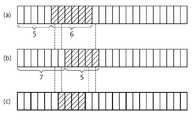
도 11은 본 발명에 따른 차동자원할당의 또 다른 예를 나타내는 도이다. 상기 도 10의 실시예를 보다 구체적으로 설명한다.11 is a diagram illustrating another example of differential resource allocation according to the present invention. The embodiment of FIG. 10 will be described in more detail.
도 11을 참조하면, 대역폭이 5MHz이고 하향 타입2가 적용되는 경우이며, NDLRB는 25이고, 하향 타입2 자원할당필드(RIV)의 크기는 325(=25(25+1)/2)이며 9비트로 나타낼 수 있다.11, the bandwidth is 5 MHz and the
(a)는 자원블록 단위의 기준자원할당, (b)는 자원할당, (c)는 자원블록그룹 단위의 기준자원할당을 나타낸다.(a) shows a reference resource allocation in units of a resource block, (b) shows a resource allocation, and (c) shows a reference resource allocation on a resource block group basis.
(a)에 대하여 하향 타입2 기준자원할당필드(RIVref)는 다음 수학식과 같다.(a), the down-

즉, RIV는 130이다.That is, RIV is 130.
(b)에 대하여 하향 타입2 자원할당필드(RIV)는 다음 수학식과 같다.(b), the

즉, RIV는 107이다. 9비트로 나타낼 수 있다.That is, RIV is 107. 9 bits.
일 예로, 하향 타입2 차동자원할당필드(RIVdiff)를 6비트로 제한하면, "-32 내지 31" 중 하나의 값을 가질 수 있으며 다음 수학식과 같이 표현할 수 있다.For example, if the

즉, 차동자원할당필드의 값은 -23이며, 1의 보수로 나타내면 "101000"이다. 결과적으로, 기준자원할당필드는 9비트, 차동자원할당필드는 6비트를 가진다.That is, the value of the differential resource allocation field is -23, which is "101000" when expressed as a complement of 1. As a result, the reference resource allocation field has 9 bits and the differential resource allocation field has 6 bits.
다른 예로, 1의 보수 또는 2의 보수형태를 이진수로 판단하는 형태가 아니라 "-23 + 31 = 6"으로 표현할 수도 있다. 이때 "-23"에 더해지는 일정값은 31(=25-1)이다.As another example, the form of 1's complement or 2's complement can be expressed as "-23 + 31 = 6" rather than as a binary number. The constant value added to "-23" at this time is 31 (= 25 -1).
한편, (c)에 대하여 기준자원할당필드를 자원블록그룹 단위(예, 크기가 2)로 가정하면, 하향 타입2 기준자원할당필드(RIVref)는 다음 수학식과 같다. 단, 부분적으로 할당된 자원블록그룹은 할당이 되지 않은 것으로 본다.Assuming that the reference resource allocation field is a resource block group unit (e.g., size 2) with respect to (c), the

즉, 기준자원할당필드에 대하여 13개의 자원블록그룹이 존재하며, 91(=13(13+1)/2)개의 경우의 수를 나타내기 위해 기준자원할당필드의 길이는 7비트이다.That is, there are 13 resource block groups for the reference resource allocation field, and the length of the reference resource allocation field is 7 bits to represent the number of 91 (= 13 (13 + 1) / 2) cases.
하지만 RIVdiff의 계산은 상기 수학식의 RIVref가 아니라 원래의 자원블록그룹 단위에서 상기 도 11의 (c)가 계산되는 값을 기준으로 수행된다. 즉, "RIV'ref"를 계산하면 다음 수학식과 같다.However, the calculation of RIVdiff is performed not on the RIVref in the above equation but on the basis of the value of FIG. 11C calculated in the original resource block group unit. That is, "RIV 'ref " is calculated as follows.

또한, 차동자원할당필드(RIVdiff)는 다음 수학식과 같다.Also, the differential resource allocation field (RIVdiff ) is expressed by the following equation.
RIVdiff=RIV-RIV'ref=107-79=28=011100(2진수)RIVdiff = RIV-RIV 'ref = 107-79 = 28 = 011100(binary)
차동자원할당필드의 길이를 기준자원할당필드의 길이(예, 7비트)와 동일하기 맞추면, 차동자원할당필드는 "-64 ~ 63"의 범위를 가질 수 있다. 결과적으로 자원할당필드는 7비트로 줄어든다.If the length of the differential resource allocation field is equal to the length of the reference resource allocation field (e.g., 7 bits), the differential resource allocation field may have a range of "-64 to 63". As a result, the resource allocation field is reduced to 7 bits.
또 다른 예로, 상기 제2 방법에 따르면, "N'=7"이고 ΔLCRBs는 "1의 보수"로 표현하면 "-2 ~ 3"의 범위를 가지며 3비트로 표현된다.As another example, according to the second method, "N '= 7" and ΔLCRBs has a range of "-2 to 3" expressed as "1's complement" and is represented by 3 bits.

즉, ΔRIB는 20이며 5비트로 나타낼 수 있다.That is, ΔRIB is 20 and can be represented by 5 bits.
한편, 하향 타입2와 같은 연속자원할당방식에서 차동자원할당필드의 범위는 길이 부분의 자유도가 중요한 변수이고, 차동자원할당필드가 표현 가능한 LCRBs의 범위를 양수인 ΔLCRBs로 표현할 때 음수의 차동값을 고려하여 "
또한, "N'=2ΔLCRBs+1"로 설계하면 "
일 예로, 대역폭이 20MHz이고 자원블록의 개수가 100개인 경우, 본 발명에 따르면 하향 타입2 차동자원할당방식의 비트 요구량은 제1 방법과 제2 방법에 대하여 다음과 같이 정리될 수 있다.For example, when the bandwidth is 20 MHz and the number of resource blocks is 100, according to the present invention, the bit request amount of the downlink 2-D resource allocation scheme can be summarized as follows for the first method and the second method.


하향 타입2와 같은 연속자원할당방식에 대한 차동자원할당은 비트 요구량에 의해 차동자원할당필드의 범위가 크게 영향을 받지만 오프셋에 대해서는 상대적으로 큰 자유도를 갖는다. 즉, 상대적으로 작은 개수의 자원블록(또는 자원블록그룹)을 할당받는 단말은 차동자원할당방식에 의해 실질적으로 큰 자유도를 가지는 스케줄링이 가능하다.The differential resource allocation for the contiguous resource allocation scheme such as
앞서 설명한 하향 타입2에 대한 설명은 상향 타입 0 및 상향 타입 1에 대해서도 적용 가능하다. 구체적으로, 상향 타입 1은 클러스터단위로 불연속자원할당을 나타내도록 적용 가능하다.The description of the
다른 예로, 하향 타입0 방식이 적용되는 경우를 설명한다.As another example, a case where the
도 12는 본 발명에 따른 차동자원할당의 또 다른 예를 나타내는 도이다. 상기 도 10의 실시예를 보다 구체적으로 설명하는 다른 예이다.12 is a diagram illustrating another example of differential resource allocation according to the present invention. This is another example for more specifically explaining the embodiment of FIG.
대역폭이 20MHz이고 자원블록의 개수가 100개이고 자원블록그룹의 크기가 4인 경우 자원블록그룹의 개수는 25이다. 이때 25비트의 비트맵형식으로 표현될 수 있다.When the bandwidth is 20 MHz, the number of resource blocks is 100, and the size of the resource block group is 4, the number of resource block groups is 25. At this time, it can be expressed in a 25-bit bitmap format.
(a)는 기준자원할당을 나타내며 "0000110001100000001110000"이다.(a) indicates reference resource allocation and is "0000110001100000001110000".
(b)는 자원할당을 나타내며 "0000110001000000001100000"이다.(b) indicates resource allocation and is "0000110001000000001100000".
(a)와 (b)에 대하여 비트별 XOR 연산을 수행하면 "0000000000100000000010000"이 된다. 이는 (a)와 (b)에서 11번째 비트와 21번째 비트에 변화가 생김을 의미한다. 이때, "N=25, M=2, s0=11, s1=21, m=2"이라고 할 수 있으며, r값은 다음 수학식과 같이 계산된다.(a) and (b), the result is "0000000000100000000010000". This means that the 11th bit and the 21st bit are changed in (a) and (b). At this time, it can be said that N = 25, M = 2, s0 = 11, s1 = 21, m = 2, and the r value is calculated by the following equation.

이때, 변화자원블록(또는 변화자원블록그룹) 개수 필드는 "
차동연산결과필드는 "
따라서, 변화자원블록 개수 필드 및 차동연산결과필드를 합한 전체필드는 총 11비트이다.Therefore, the total field including the change resource block count field and the differential operation result field is 11 bits in total.
한편, 변화자원블록 개수(또는 변화자원블록그룹 개수)에 따른 요구 비트량은 다음 표와 같다.Meanwhile, the required bit amount according to the number of change resource blocks (or the number of change resource block groups) is shown in the following table.
만약 기준자원할당필드를 자원할당필드의 크기와 동일하도록 자원블록그룹의 크기를 "8비트"로 늘이면 상기 도 12 (c)와 같이 13비트("0010100001000")로 나타낼 수 있다.이때, 차동자원할당필드의 앞부분에 2비트의 제로 패딩(zero padding) 비트를 삽입하여 길이를 동일하도록 맞출 수 있다.If the size of the resource block group is increased to "8 bits" so that the reference resource allocation field is equal to the size of the resource allocation field, 13 bits ("0010100001000") as shown in FIG. 12C can be represented. It is possible to align the lengths by inserting 2 bits of zero padding bits at the beginning of the resource allocation field.
상기 제2 방법을 사용하여 변화되는 비트의 최대 개수를 4개로 한정하면, 요구 비트량은 14비트이며, 기준자원할당필드에 제로 패딩 비트를 삽입하여 14비트로 맞출 수 있다. 자원블록그룹의 크기를 8로 늘어났지만 r값은 "0000110011000000001100000"에 맞춘다.If the maximum number of bits changed by using the second method is limited to four, the requested bit amount is 14 bits, and the zero padding bit may be inserted into the reference resource allocation field to be set to 14 bits. The size of the resource block group is increased to 8, but the r value is set to "0000110011000000001100000".
(b)와 (c)에 비트별 XOR 연산을 수행하면 "0000000010000000000000000"이다. 여기서, s0=9, m=1, 이며, r값은 다음 수학식과 같이 계산된다.(b) and (c), "0000000010000000000000000". Here, s0 = 9, m = 1, and the r value is calculated by the following equation.

즉, 25비트의 자원할당필드가 13비트로 줄어드는 효과가 있다.That is, the 25-bit resource allocation field is reduced to 13 bits.
한편, 상대적으로 작은 자원블록그룹을 할당받는 단말은 차동자원할당방식이 큰 자유도를 가지는 스케줄링이 가능하다.On the other hand, a UE having a relatively small resource block group can perform scheduling with a large degree of freedom in a differential resource allocation scheme.
25개의 자원블록그룹 중 2개의 자원블록그룹을 할당받은 단말은 차동자원필드를 14비트로 표현할 수 있다. 4개 자원블록그룹의 변화가 가능한 경우 자원블록그룹의 크기가 2개로 한정된다는 조건 이외에는 실질적으로 완전한 유연성(full flexibility)을 갖는다.A UE allocated two resource block groups out of the 25 resource block groups can represent the differential resource field with 14 bits. There is substantially full flexibility except that the size of the resource block group is limited to two when the change of the four resource block groups is possible.
앞서 설명은 일반적인 모든 자원할당방식에 가능하지만 하향 타입0 및 하향 타입 1에 대해서 특히 잘 적용할 수 있다.The above description is applicable to all common resource allocation schemes, but it is particularly well suited for
하향 타입1에 대해서는 세 개의 필드(즉, 서브셋지시필드 비트, 오프셋여부필드, 비트맵을 나타내는 비트)가 존재한다.For
또한, 하향 타입 0을 나타내는 구분지시자가 추가적으로 존재할 수 있다.In addition, a division indicator indicating a
차동자원할당방식을 사용하는 경우 비트맵에 해당하는 필드가 고려되지만 비트맵을 나타내는 필드 이외의 서브셋지시필드, 오프셋여부필드가 선택적으로 포함되어 확장된 비트맵형태로 차동자원할당방식에 적용될 수 있다.When a differential resource allocation scheme is used, a field corresponding to a bitmap is considered, but a subset indication field other than the field indicating the bitmap field and an offset field may be selectively applied to the differential resource allocation scheme in the form of an extended bitmap .
앞서 설명한 바를 정리하면, 본 발명에 따라서 하향 타입 2, 상향 타입 0, 상향 타입 1에 대해서 제1 방법 또는 제2 방법으로 다음 표와 같이 차동자원할당필드를 구성할 수 있다.In accordance with the present invention, the differential resource allocation field can be configured according to the first method or the second method for the
다른 예로, 본 발명에 따라서 하향 타입 0, 하향 타입 1에 대해서 제1 방법 또는 제2 방법으로 다음 표와 같이 차동자원할당필드를 구성할 수 있다.As another example, according to the present invention, a differential resource allocation field can be configured as a first method or a second method for down-

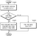
도 13은 본 발명에 따라서 차동자원할당방식과 관련된 기지국의 동작의 일 예를 나타내는 순서도이다.13 is a flowchart showing an example of the operation of the base station related to the differential resource allocation scheme according to the present invention.
도 13을 참조하면, 기지국은 상향링크 및 하향링크의 채널 상황 및 상태를 단말별로 확인한다(S1300).Referring to FIG. 13, the base station checks the uplink and downlink channel status and status for each UE (S1300).
하향링크의 채널 상황 및 상태는 단말의 궤환정보(feedback information)에 의해 결정될 수 있다. 궤환정보란 단말에서 기지국으로 전송되는 모든 활용가능한 정보를 말한다. 일 예로, 상기 단말의 궤환 정보는 채널상태측정정보를 포함할 수 있으며, 상기 단말의 궤환정보는 HARQ ACK/NACK, PMI, RI, CQI, RSRQ, RSRP 또는 RSSI 정보 또는 단말단에서 측정한 단말의 속도정보를 포함할 수 있다. 단말은 상기 궤환정보를 기초로 채널이 안정적(static)인지 여부를 판단할 수 있다.The channel status and status of the downlink can be determined by the feedback information of the UE. Feedback information refers to all available information transmitted from the UE to the BS. For example, the feedback information of the UE may include channel state measurement information, and the feedback information of the UE may include HARQ ACK / NACK, PMI, RI, CQI, RSRQ, RSRP or RSSI information, Speed information. The UE can determine whether the channel is static based on the feedback information.
단계 S1300에 이어서, 기지국은 상기 단말의 궤환정보를 기초로 단말이 차동자원할당방식을 적용하는 것이 적합한지 여부를 판단할 수 있다(S1305). 상기 판단 알고리즘은 scheduler 알고리듬에 포함될 수 있다.Following step S1300, the base station can determine whether it is appropriate for the UE to apply the differential resource allocation scheme based on the feedback information of the terminal (S1305). The decision algorithm may be included in the scheduler algorithm.
다른 예로, 기지국은 상기 단말의 궤환정보를 기초로 결정된 하향링크의 채널 상황 및 상태를 기초로 차동자원할당방식을 적용하는 것이 적합한 지 여부를 판단할 수 있다.In another example, the base station may determine whether it is appropriate to apply the differential resource allocation scheme based on the downlink channel status and status determined based on the feedback information of the UE.
단계 S1305에서 기지국이 차동자원할당방식을 적용하기로 판단하면, 기지국은 단말 특정적으로(UE specific) 상위계층시그널링(예, RRC 시그널링)을 통해 차동자원할당을 적용할 것(또는 기존의 차동자원할당방식을 유지할 것)을 단말에게 지시한다(S1310). 상기 차동자원할당은 상기 도 7 내지 도 12에서 설명한 방법 중 하나일 수 있다.In step S1305, if the base station determines to apply the differential resource allocation scheme, the base station applies differential resource allocation through UE-specific upper layer signaling (e.g., RRC signaling) (or uses existing differential resources And keep the allocation scheme) to the terminal (S1310). The differential resource allocation may be one of the methods described in FIG. 7 to FIG.
상기 상위계층시그널링은 RRC 구성(configuration)에 포함될 수 있으며, 상기 상위계층시그널링은 기준자원할당필드의 구성에 필요한 정보(예, 일정서브프레임주기에서 몇 번째 서브프레임인지에 관한 정보 또는 일정주기에서 처음 복호되는 서브프레임인지 여부에 대한 정보)를 포함할 수 있다.The upper layer signaling may be included in a RRC configuration, and the upper layer signaling may include information necessary for configuration of a reference resource allocation field (e.g., information on how many subframes are in a certain subframe period, Information on whether or not the subframe is a decoded subframe).
전송모드(Transmission Mode)를 대표하는 DCI 포맷(예, DCI 포맷 2C)은 차동자원할당모드를 적용하고 DCI 포맷 0/1A는 기존의 자원할당모드를 적용할 수 있다.The DCI format (for example, DCI format 2C) representing the transmission mode applies the differential resource allocation mode, and the
또한, 차동자원할당모드를 적용하는지 여부에 관한 정보가 상기 상위계층시그널링에 포함될 수 있다. 차동자원할당모드를 적용하는 포맷과 적용하지 않는 포맷에 대한 시그널링 또는 구성이 독립적일 수 있다.In addition, information on whether or not to apply the differential resource allocation mode may be included in the upper layer signaling. The format for applying the differential resource allocation mode and the signaling or configuration for the non-applied format may be independent.
단계 S1305에서 기지국이 차동자원할당방식을 적용하기 않기로 판단하면, 기지국은 상위계층시그널링에 의해 단말 특정적으로 기존자원할당방식을 설정(또는 기존자원할당방식을 유지)할 것을 단말에게 지시한다(S1315).If it is determined in step S1305 that the base station does not apply the differential resource allocation scheme, the base station instructs the terminal to set an existing resource allocation scheme (or maintain the existing resource allocation scheme) in a UE-specific manner by higher layer signaling (S1315 ).
도 14는 본 발명에 따라서 차동자원할당방식과 관련된 장치의 동작의 일 예를 나타내는 순서도이다.14 is a flowchart showing an example of the operation of the apparatus related to the differential resource allocation scheme according to the present invention.
도 14를 참조하면, 각 단말은 상위계층시그널링을 기지국과 수행한다(S1400).Referring to FIG. 14, each terminal performs upper layer signaling with a base station (S1400).
상기 상위계층시그널링에서 지시하는 자원할당이 차동자원할당방식이면, 단말은 차동자원할당방식으로 자원할당(예, 블라인드복호)을 수행한다(S1405).If the resource allocation indicated in the upper layer signaling is a differential resource allocation scheme, the terminal performs resource allocation (e.g., blind decoding) in a differential resource allocation scheme (S1405).
상기 상위계층시그널링에서 지시하는 자원할당이 차동자원할당방식이 아니면, 단말은 기존자원할당방식으로 자원할당을 수행한다(S1410).If the resource allocation indicated by the higher layer signaling is not the differential resource allocation scheme, the MS performs resource allocation using an existing resource allocation scheme (S1410).
한편, 본 발명에 따라서 차동자원할당방식과 관련된 기지국은 프로세서 및 전송부를 포함할 수 있다.Meanwhile, the base station related to the differential resource allocation scheme according to the present invention may include a processor and a transmission unit.
프로세서는 상향링크 및 하향링크의 채널 상황 및 상태를 단말별로 확인한다.The processor checks the uplink and downlink channel status and status for each UE.
프로세서는 상향링크 및 하향링크의 채널 상태를 단말의 궤환정보(feedback information)를 기초로 확인한다.The processor confirms the uplink and downlink channel states based on the feedback information of the UE.
또는 프로세서는 상기 단말의 궤환정보를 기초로 단말이 차동자원할당방식을 적용하는 것이 적합한지 여부를 판단한다.Or the processor determines whether it is appropriate for the UE to apply the differential resource allocation scheme based on the feedback information of the UE.
전송부는 단말 특정적으로(UE specific) 상위계층시그널링(예, RRC 시그널링)을 통해 차동자원할당을 적용할 것(또는 기존의 차동자원할당방식을 유지할 것)을 단말에게 지시한다. 상기 차동자원할당은 상기 도 7 내지 도 12에서 설명한 방법 중 하나일 수 있다. 상기 상위계층시그널링은 RRC 구성(configuration)에 포함될 수 있으며, 상기 상위계층시그널링은 기준자원할당필드의 구성에 필요한 정보(예, 일정서브프레임주기에서 몇 번째 서브프레임인지에 관한 정보 또는 일정주기에서 처음 복호되는 서브프레임인지 여부에 대한 정보)를 포함할 수 있다.The transmitting unit instructs the UE to apply differential resource allocation (or maintain the existing differential resource allocation scheme) through UE-specific upper layer signaling (e.g., RRC signaling). The differential resource allocation may be one of the methods described in FIG. 7 to FIG. The upper layer signaling may be included in a RRC configuration, and the upper layer signaling may include information necessary for configuration of a reference resource allocation field (e.g., information on how many subframes are in a certain subframe period, Information on whether or not the subframe is a decoded subframe).
또는, 전송부는 상위계층시그널링에 의해 단말 특정적으로 기존자원할당방식을 설정(또는 기존자원할당방식을 유지)할 것을 단말에게 지시한다.Alternatively, the transmitting unit instructs the UE to set an existing resource allocation scheme (or maintain an existing resource allocation scheme) in a UE-specific manner by upper layer signaling.
본 발명이 속하는 기술분야에서 통상의 지식을 가진 자라면, 본 발명의 기술적 사상을 벗어나지 않는 범위 내에서, 여러 가지 치환, 변형 및 변경이 가능하므로, 본 발명은 전술한 실시 예 및 첨부된 도면에 의해 한정되는 것이 아니다.It will be apparent to those skilled in the art that various modifications and variations can be made in the present invention without departing from the spirit or scope of the inventive concept as defined by the appended claims. But is not limited thereto.
상술한 예시적인 시스템에서, 방법들은 일련의 단계 또는 블록으로써 순서도를 기초로 설명되고 있지만, 본 발명은 단계들의 순서에 한정되는 것은 아니며, 어떤 단계는 상술한 바와 다른 단계와 다른 순서로 또는 동시에 발생할 수 있다. 또한, 당업자라면 순서도에 나타낸 단계들이 배타적이지 않고, 다른 단계가 포함되거나 순서도의 하나 또는 그 이상의 단계가 본 발명의 범위에 영향을 미치지 않고 삭제될 수 있음을 이해할 수 있을 것이다.In the above-described exemplary system, the methods are described on the basis of a flowchart as a series of steps or blocks, but the present invention is not limited to the order of the steps, and some steps may occur in different orders or simultaneously . It will also be understood by those skilled in the art that the steps shown in the flowchart are not exclusive and that other steps may be included or that one or more steps in the flowchart may be deleted without affecting the scope of the invention.
Claims (17)
Translated fromKoreanHARQ ACK/NACK(Hybrid Automatic Repeat reQuest Acknowledgement/Non-ackowledgement)를 포함하는 단말의 궤환정보(feedback information)를 기초로 단말에 대한 상향링크 및 하향링크의 채널 상태를 확인하는 단계;
상기 단말의 궤환 정보를 기초로 차동자원할당을 적용하는 것이 적합한지 여부를 판단하는 단계; 및
상기 차동자원할당의 적용을 상기 단말에게 상위계층 시그널링을 통해 지시하는 단계를 포함하는 방법.A transmission method of a control channel including differential resource allocation information by a base station,
Confirming uplink and downlink channel states for a UE based on feedback information of a UE including HARQ ACK / NACK (Hybrid Automatic Repeat reQuest Acknowledgment / Non-acknowledgment);
Determining whether it is appropriate to apply the differential resource allocation based on the feedback information of the terminal; And
Indicating the application of the differential resource allocation to the terminal through higher layer signaling.
기준자원할당필드와 자원할당필드의 비트별 XOR 연산을 통해 수행되는 것을 특징으로 하는 방법.2. The method of claim 1, wherein the differential resource allocation
And performing bitwise XOR operations on the reference resource allocation field and the resource allocation field.
상기 비트별 XOR 연산 결과 중 변화된 자원블록 또는 자원블록그룹 부분에 대하여 열거원천부호화를 수행함을 더 포함하는 것을 특징으로 하는 방법.3. The method of claim 2, wherein the differential resource allocation
And performing enumerative source coding on the changed resource block or the resource block group part of the bit-by-bit XOR operation result.
상기 비트별 XOR 연산에 따라서 변화된 자원블록 또는 자원블록그룹 부분의 비트 수에 대한 정보를 단말로 전송하는 단계를 더 포함하는 방법.The method of claim 3,
And transmitting information on the number of bits of the resource block or the resource block group portion changed according to the bitwise XOR operation to the terminal.
상기 비트별 XOR 연산에 따라서 변화된 자원블록 또는 자원블록그룹 부분의 비트 수에 대한 정보를 포함하는 변화자원블록개수 필드 및 차동연산결과필드로 구성되는 것을 특징으로 하는 방법.5. The method of claim 4, wherein the differential resource allocation field comprises:
A change resource block number field and a differential operation result field including information on the number of bits of a resource block or a resource block group portion changed according to the bitwise XOR operation.
상기 차동자원할당필드와 크기가 동일하도록 제로 패딩(zero padding)을 이용하여 자원블록그룹의 크기가 증가된 것을 특징으로 하는 방법.2. The method of claim 1,
Wherein a size of the resource block group is increased using zero padding so that the size of the resource block group is equal to the size of the differential resource allocation field.
RRC 시그널링에 의해 상기 단말에게 알려지거나, 상기 자원할당필드가 속한 PDCCH에 의해 자원할당되는 PDSCH 또는 PUSCH를 포함하는 서브프레임 바로 이전에 스케줄링된 PDSCH 또는 PUSCH에 대하여 자원할당하는 필드로 상기 단말에게 알려지거나,소정의 개수의 서브프레임을 주기로 하여 각 주기에서 가장 먼저 스케줄링된 PDSCH 또는 PUSCH의 자원할당을 지시하는 자원할당필드로 상기 단말에게 알려지거나, 소정의 개수의 서브프레임을 주기로 하여 각 주기 내 가장 먼저 복호되어 검출되는 서브프레임에 존재하는 PDCCH에 포함되는 자원할당필드로 상기 단말에게 알려지거나, 상기 가장 먼저 복호되어 검출되는 서브프레임에 존재하는 PDSCH 또는 PUSCH를 스케줄링하는 PDCCH에 포함되는 자원할당필드로 상기 단말에게 알려지는 것을 특징으로 하는 방법.2. The method of claim 1,
The UE is informed to the UE of a resource allocated to a PDSCH or a PUSCH scheduled immediately before a subframe including a PDSCH or a PUSCH that is known to the UE by RRC signaling or is allocated by a PDCCH to which the resource allocation field belongs , A resource allocation field indicating a resource allocation of a first scheduled PDSCH or a PUSCH in a period of a predetermined number of subframes as a period, A resource allocation field included in a PDCCH for scheduling a PDSCH or a PUSCH existing in a subframe that is known to the UE as a resource allocation field included in a PDCCH present in a decoded and detected subframe, And is notified to the terminal.
특정 서브프레임에서 상기 기준자원할당필드 길이에 해당하는 PDCCH가 복호되어 상기 기준자원할당필드의 존재가 확인되는 경우 차동자원할당방식을 사용함으로 기지국과 단말간에 설정되는 것을 특징으로 하는 방법.2. The method of claim 1, wherein whether to perform the differential resource allocation scheme comprises:
Wherein a PDCCH corresponding to the reference resource allocation field length is decoded in a specific subframe so that existence of the reference resource allocation field is confirmed, and the differential resource allocation scheme is used between the BS and the UE.
상기 기준자원할당필드의 특정 위치의 비트값과 대응하는 상기 자원할당필드의 비트값이 동일하면 해당 위치에 대한 차동연산 결과는 0이고,
상기 기준자원할당필드의 특정 위치의 비트값과 대응하는 상기 자원할당필드의 비트값이 다르면 해당 위치에 대한 차동연산 결과는1인 것을 특징으로 하는 방법.3. The method of claim 2, wherein the bitwise XOR operation
If the bit value of the specific location in the reference resource allocation field and the bit value of the corresponding resource allocation field are the same, the differential operation result for the location is 0,
Wherein if the bit value of the specific location of the reference resource allocation field differs from the bit value of the corresponding resource allocation field, the differential operation result for the location is 1.
자원블록이 비트맵 형식으로 할당되거나, 소정의 간격 또는 주기로 할당되거나, 연속된 일정 길이의 영역으로서 할당되는 것을 특징으로 하는 방법.2. The method of claim 1,
Wherein the resource blocks are allocated in a bit map format, allocated at predetermined intervals or periods, or allocated as regions of a continuous constant length.
상기 차동자원할당필드 범위의 제한 또는 필드 길이는 대역폭별로 결정되는 것을 특징으로 하는 방법.The method according to claim 1,
Wherein the limitation of the differential resource allocation field range or the field length is determined for each bandwidth.
상기 차동자원할당필드의 값(value)은 1의 보수 또는 2의 보수형태이고,
상기 차동자원할당필드 값이 표현가능한 양의 범위 또는 음의 범위를 벗어가는 경우, 상기 양의 범위의 최대값 또는 상기 음의 범위의 최소값으로 고정되는 것을 특징으로 하는 방법.The method according to claim 1,
The value of the differential resource allocation field is a 1's complement or 2's complement,
Wherein the differential resource allocation field value is fixed to a maximum value of the positive range or a minimum value of the negative range when the value of the differential resource allocation field falls outside the expressible positive or negative range.
HARQ ACK/NACK(Hybrid Automatic Repeat reQuest Acknowledgement/Non-ackowledgement)를 포함하는 단말의 궤환정보(feedback information)를 기초로 단말에 대한 상향링크 및 하향링크의 채널 상태를 확인하고, 상기 단말의 궤환 정보를 기초로 차동자원할당을 적용하는 것이 적합한지 여부를 판단하는 프로세서; 및
상기 차동자원할당의 적용을 상기 단말에게 상위계층 시그널링을 통해 지시하는 전송부를 포함하는 기지국.A base station for transmitting a control channel including differential resource allocation information,
The method includes confirming uplink and downlink channel conditions for a UE based on feedback information of the UE including HARQ ACK / NACK (Hybrid Automatic Repeat reQuest Acknowledgment / Non-acknowledgment) A processor for determining whether applying a differential resource allocation as a basis is appropriate; And
And a transmitter for instructing the terminal to apply the differential resource allocation through higher layer signaling.
상기 프로세서는 기준자원할당필드와 자원할당필드의 비트별 XOR 연산을 기초로 상기 차동자원할당을 수행하는 것을 특징으로 하는 기지국.14. The method of claim 13,
Wherein the processor performs the differential resource allocation based on a bitwise XOR operation of a reference resource allocation field and a resource allocation field.
상기 비트별 XOR 연산 결과 중 변화된 자원블록 또는 자원블록그룹 부분에 대하여 열거원천부호화를 수행함을 더 포함하는 것을 특징으로 하는 기지국.15. The method of claim 14, wherein the differential resource allocation
Further comprising performing enumerative source coding on a changed resource block or a resource block group portion of the bit-by-bit XOR operation result.
상기 비트별 XOR 연산에 따라서 변화된 자원블록 또는 자원블록그룹 부분의 비트 수에 대한 정보를 단말로 전송하는 것을 특징으로 하는 기지국.16. The apparatus of claim 15,
And transmits information on the number of bits of the resource block or the resource block group portion changed according to the bit-by-bit XOR operation to the UE.
상기 비트별 XOR 연산에 따라서 변화된 자원블록 또는 자원블록그룹 부분의 비트 수에 대한 정보를 포함하는 변화자원블록개수 필드 및 차동연산결과필드로 구성되는 것을 특징으로 하는 기지국.17. The method of claim 16, wherein the differential resource allocation field comprises:
A change resource block number field and a differential operation result field including information on the number of bits of a resource block or a resource block group portion changed according to the bit-by-bit XOR operation.
Priority Applications (2)
| Application Number | Priority Date | Filing Date | Title |
|---|---|---|---|
| KR1020130054629AKR20140134561A (en) | 2013-05-14 | 2013-05-14 | Apparatus and method for transmitting or receiving control channel including differential resource allocation information |
| PCT/KR2014/004314WO2014185703A1 (en) | 2013-05-14 | 2014-05-14 | Apparatus and method for transmitting and receiving control channel including differential resource allocation information |
Applications Claiming Priority (1)
| Application Number | Priority Date | Filing Date | Title |
|---|---|---|---|
| KR1020130054629AKR20140134561A (en) | 2013-05-14 | 2013-05-14 | Apparatus and method for transmitting or receiving control channel including differential resource allocation information |
Publications (1)
| Publication Number | Publication Date |
|---|---|
| KR20140134561Atrue KR20140134561A (en) | 2014-11-24 |
Family
ID=51898618
Family Applications (1)
| Application Number | Title | Priority Date | Filing Date |
|---|---|---|---|
| KR1020130054629AWithdrawnKR20140134561A (en) | 2013-05-14 | 2013-05-14 | Apparatus and method for transmitting or receiving control channel including differential resource allocation information |
Country Status (2)
| Country | Link |
|---|---|
| KR (1) | KR20140134561A (en) |
| WO (1) | WO2014185703A1 (en) |
Families Citing this family (3)
| Publication number | Priority date | Publication date | Assignee | Title |
|---|---|---|---|---|
| CN107347002B (en)* | 2016-05-06 | 2021-11-12 | 北京三星通信技术研究有限公司 | Method and device for transmitting HARQ-ACK feedback information |
| EP3797483B1 (en)* | 2018-09-28 | 2024-06-19 | Huawei Technologies Co., Ltd. | Devices, methods and computer programs for adaptively selective retransmission in wireless communications |
| CN113993213B (en)* | 2021-09-14 | 2025-04-29 | 苏州星恒通导航技术有限公司 | A differential resource time-sharing management system and method for positioning terminal |
Family Cites Families (5)
| Publication number | Priority date | Publication date | Assignee | Title |
|---|---|---|---|---|
| WO2007008123A1 (en)* | 2005-07-07 | 2007-01-18 | Telefonaktiebolaget Lm Ericsson (Publ) | Method and arrangement for coding and scheduling in packet data communication systems |
| KR101753926B1 (en)* | 2009-10-22 | 2017-07-04 | 인터디지탈 패튼 홀딩스, 인크 | Method and apparatus for a two-way relaying scheme with physical layer network coding |
| KR101201946B1 (en)* | 2009-12-02 | 2012-11-16 | 한국과학기술원 | Apparatus and method of simultaneous control and data signal transmission via network coding in a wireless communication system |
| US8514796B2 (en)* | 2010-04-01 | 2013-08-20 | Sharp Laboratories Of America, Inc. | Transmitting control data and user data on a physical uplink channel |
| US8634345B2 (en)* | 2010-06-18 | 2014-01-21 | Sharp Laboratories Of America, Inc. | Uplink control information (UCI) multiplexing on the physical uplink shared channel (PUSCH) |
- 2013
- 2013-05-14KRKR1020130054629Apatent/KR20140134561A/ennot_activeWithdrawn
- 2014
- 2014-05-14WOPCT/KR2014/004314patent/WO2014185703A1/enactiveApplication Filing
Also Published As
| Publication number | Publication date |
|---|---|
| WO2014185703A1 (en) | 2014-11-20 |
Similar Documents
| Publication | Publication Date | Title |
|---|---|---|
| CN108696943B (en) | Method for transmitting and receiving data channel for new radio and apparatus using the same | |
| CN109478978B (en) | Carrier Aggregation with Variable Transmission Duration | |
| JP7331204B2 (en) | Terminal and communication method | |
| CN115150023B (en) | Uplink transmission method and device in cellular communication system | |
| JP5964468B2 (en) | Control channel resources for multi-bit ACK / NAK | |
| KR102284453B1 (en) | Method and apparatus for uplink control information transmission in wirelee cellular communication systems | |
| EP2409438B1 (en) | Configuring the transmission of periodic feedback information on a physical uplink shared channel (pusch) | |
| JP5824566B2 (en) | Base station, user apparatus, communication method, and integrated circuit for allocating physical uplink control channel resources | |
| CN116134934A (en) | Multi-cell scheduling with reduced control overhead | |
| CN104025496B (en) | Method and apparatus for scalable and scalable control channels for wireless networks | |
| US9609637B2 (en) | Override of multi-TTI scheduling messages | |
| KR102330319B1 (en) | Method and apparatus for radio link monitoring in wireless communcation system | |
| EP2936910B1 (en) | Non-consecutive subframes in multi-tti scheduling messages | |
| KR102359788B1 (en) | Method and apparatus for scheduling in wireless communication system providing widebandwidth service | |
| US20130051356A1 (en) | Device and method for transmitting downlink control information in a wireless communication system | |
| CN114258650A (en) | Apparatus and method for managing soft buffers in a wireless communication system | |
| KR20120116271A (en) | Method and apparatus of operating subframe and transmitting channel state information for controlling interference in communication system | |
| CN115134062B (en) | Method and apparatus for setting multiple DMRS structures in wireless cellular communication system | |
| KR20140121319A (en) | Method and apparatus for transmitting channel state information in wireless communication system | |
| US20120307776A1 (en) | Base station resource allocation method in a wireless communication system and a device for the same | |
| US12376076B2 (en) | Methods and apparatus for resource reservation in narrowband Internet of Things communications | |
| CN102447529B (en) | The transmission method and device of a kind of control channel | |
| JP2022141774A (en) | Terminal, communication method, and integrated circuit | |
| EP3065452B1 (en) | User terminal, base station, and radio communication method | |
| KR20140134207A (en) | Method for Determining Transport Block Size and Apparatuses thereof |
Legal Events
| Date | Code | Title | Description |
|---|---|---|---|
| PA0109 | Patent application | Patent event code:PA01091R01D Comment text:Patent Application Patent event date:20130514 | |
| PG1501 | Laying open of application | ||
| N231 | Notification of change of applicant | ||
| PN2301 | Change of applicant | Patent event date:20160801 Comment text:Notification of Change of Applicant Patent event code:PN23011R01D | |
| PC1203 | Withdrawal of no request for examination | ||
| WITN | Application deemed withdrawn, e.g. because no request for examination was filed or no examination fee was paid |