KR20140132811A - Ultrasound imaging apparatus and control method for the same - Google Patents
Ultrasound imaging apparatus and control method for the sameDownload PDFInfo
- Publication number
- KR20140132811A KR20140132811AKR1020130050928AKR20130050928AKR20140132811AKR 20140132811 AKR20140132811 AKR 20140132811AKR 1020130050928 AKR1020130050928 AKR 1020130050928AKR 20130050928 AKR20130050928 AKR 20130050928AKR 20140132811 AKR20140132811 AKR 20140132811A
- Authority
- KR
- South Korea
- Prior art keywords
- groups
- ultrasonic
- vibrators
- signal
- image
- Prior art date
- Legal status (The legal status is an assumption and is not a legal conclusion. Google has not performed a legal analysis and makes no representation as to the accuracy of the status listed.)
- Ceased
Links
Images


Classifications
- A—HUMAN NECESSITIES
- A61—MEDICAL OR VETERINARY SCIENCE; HYGIENE
- A61B—DIAGNOSIS; SURGERY; IDENTIFICATION
- A61B8/00—Diagnosis using ultrasonic, sonic or infrasonic waves
- A61B8/44—Constructional features of the ultrasonic, sonic or infrasonic diagnostic device
- A61B8/4483—Constructional features of the ultrasonic, sonic or infrasonic diagnostic device characterised by features of the ultrasound transducer
- A61B8/4494—Constructional features of the ultrasonic, sonic or infrasonic diagnostic device characterised by features of the ultrasound transducer characterised by the arrangement of the transducer elements
- G—PHYSICS
- G01—MEASURING; TESTING
- G01N—INVESTIGATING OR ANALYSING MATERIALS BY DETERMINING THEIR CHEMICAL OR PHYSICAL PROPERTIES
- G01N29/00—Investigating or analysing materials by the use of ultrasonic, sonic or infrasonic waves; Visualisation of the interior of objects by transmitting ultrasonic or sonic waves through the object
- G01N29/22—Details, e.g. general constructional or apparatus details
- G01N29/24—Probes
- A—HUMAN NECESSITIES
- A61—MEDICAL OR VETERINARY SCIENCE; HYGIENE
- A61B—DIAGNOSIS; SURGERY; IDENTIFICATION
- A61B8/00—Diagnosis using ultrasonic, sonic or infrasonic waves
- A61B8/13—Tomography
- A61B8/14—Echo-tomography
- A61B8/145—Echo-tomography characterised by scanning multiple planes
- A—HUMAN NECESSITIES
- A61—MEDICAL OR VETERINARY SCIENCE; HYGIENE
- A61B—DIAGNOSIS; SURGERY; IDENTIFICATION
- A61B8/00—Diagnosis using ultrasonic, sonic or infrasonic waves
- A61B8/44—Constructional features of the ultrasonic, sonic or infrasonic diagnostic device
- A61B8/4483—Constructional features of the ultrasonic, sonic or infrasonic diagnostic device characterised by features of the ultrasound transducer
- A61B8/4488—Constructional features of the ultrasonic, sonic or infrasonic diagnostic device characterised by features of the ultrasound transducer the transducer being a phased array
- A—HUMAN NECESSITIES
- A61—MEDICAL OR VETERINARY SCIENCE; HYGIENE
- A61B—DIAGNOSIS; SURGERY; IDENTIFICATION
- A61B8/00—Diagnosis using ultrasonic, sonic or infrasonic waves
- A61B8/46—Ultrasonic, sonic or infrasonic diagnostic devices with special arrangements for interfacing with the operator or the patient
- A61B8/461—Displaying means of special interest
- A61B8/463—Displaying means of special interest characterised by displaying multiple images or images and diagnostic data on one display
- A—HUMAN NECESSITIES
- A61—MEDICAL OR VETERINARY SCIENCE; HYGIENE
- A61B—DIAGNOSIS; SURGERY; IDENTIFICATION
- A61B8/00—Diagnosis using ultrasonic, sonic or infrasonic waves
- A61B8/52—Devices using data or image processing specially adapted for diagnosis using ultrasonic, sonic or infrasonic waves
- A61B8/5207—Devices using data or image processing specially adapted for diagnosis using ultrasonic, sonic or infrasonic waves involving processing of raw data to produce diagnostic data, e.g. for generating an image
- A—HUMAN NECESSITIES
- A61—MEDICAL OR VETERINARY SCIENCE; HYGIENE
- A61B—DIAGNOSIS; SURGERY; IDENTIFICATION
- A61B8/00—Diagnosis using ultrasonic, sonic or infrasonic waves
- A61B8/54—Control of the diagnostic device
- G—PHYSICS
- G01—MEASURING; TESTING
- G01S—RADIO DIRECTION-FINDING; RADIO NAVIGATION; DETERMINING DISTANCE OR VELOCITY BY USE OF RADIO WAVES; LOCATING OR PRESENCE-DETECTING BY USE OF THE REFLECTION OR RERADIATION OF RADIO WAVES; ANALOGOUS ARRANGEMENTS USING OTHER WAVES
- G01S15/00—Systems using the reflection or reradiation of acoustic waves, e.g. sonar systems
- G01S15/88—Sonar systems specially adapted for specific applications
- G01S15/89—Sonar systems specially adapted for specific applications for mapping or imaging
- G01S15/8906—Short-range imaging systems; Acoustic microscope systems using pulse-echo techniques
- G01S15/8909—Short-range imaging systems; Acoustic microscope systems using pulse-echo techniques using a static transducer configuration
- G01S15/8915—Short-range imaging systems; Acoustic microscope systems using pulse-echo techniques using a static transducer configuration using a transducer array
- G—PHYSICS
- G01—MEASURING; TESTING
- G01S—RADIO DIRECTION-FINDING; RADIO NAVIGATION; DETERMINING DISTANCE OR VELOCITY BY USE OF RADIO WAVES; LOCATING OR PRESENCE-DETECTING BY USE OF THE REFLECTION OR RERADIATION OF RADIO WAVES; ANALOGOUS ARRANGEMENTS USING OTHER WAVES
- G01S15/00—Systems using the reflection or reradiation of acoustic waves, e.g. sonar systems
- G01S15/88—Sonar systems specially adapted for specific applications
- G01S15/89—Sonar systems specially adapted for specific applications for mapping or imaging
- G01S15/8906—Short-range imaging systems; Acoustic microscope systems using pulse-echo techniques
- G01S15/8909—Short-range imaging systems; Acoustic microscope systems using pulse-echo techniques using a static transducer configuration
- G01S15/8929—Short-range imaging systems; Acoustic microscope systems using pulse-echo techniques using a static transducer configuration using a three-dimensional transducer configuration
- G—PHYSICS
- G01—MEASURING; TESTING
- G01S—RADIO DIRECTION-FINDING; RADIO NAVIGATION; DETERMINING DISTANCE OR VELOCITY BY USE OF RADIO WAVES; LOCATING OR PRESENCE-DETECTING BY USE OF THE REFLECTION OR RERADIATION OF RADIO WAVES; ANALOGOUS ARRANGEMENTS USING OTHER WAVES
- G01S15/00—Systems using the reflection or reradiation of acoustic waves, e.g. sonar systems
- G01S15/88—Sonar systems specially adapted for specific applications
- G01S15/89—Sonar systems specially adapted for specific applications for mapping or imaging
- G01S15/8906—Short-range imaging systems; Acoustic microscope systems using pulse-echo techniques
- G01S15/895—Short-range imaging systems; Acoustic microscope systems using pulse-echo techniques characterised by the transmitted frequency spectrum
- G—PHYSICS
- G10—MUSICAL INSTRUMENTS; ACOUSTICS
- G10K—SOUND-PRODUCING DEVICES; METHODS OR DEVICES FOR PROTECTING AGAINST, OR FOR DAMPING, NOISE OR OTHER ACOUSTIC WAVES IN GENERAL; ACOUSTICS NOT OTHERWISE PROVIDED FOR
- G10K11/00—Methods or devices for transmitting, conducting or directing sound in general; Methods or devices for protecting against, or for damping, noise or other acoustic waves in general
- G10K11/18—Methods or devices for transmitting, conducting or directing sound
- G10K11/26—Sound-focusing or directing, e.g. scanning
- G10K11/34—Sound-focusing or directing, e.g. scanning using electrical steering of transducer arrays, e.g. beam steering
- A—HUMAN NECESSITIES
- A61—MEDICAL OR VETERINARY SCIENCE; HYGIENE
- A61B—DIAGNOSIS; SURGERY; IDENTIFICATION
- A61B8/00—Diagnosis using ultrasonic, sonic or infrasonic waves
- A61B8/13—Tomography
- A61B8/14—Echo-tomography
- A—HUMAN NECESSITIES
- A61—MEDICAL OR VETERINARY SCIENCE; HYGIENE
- A61B—DIAGNOSIS; SURGERY; IDENTIFICATION
- A61B8/00—Diagnosis using ultrasonic, sonic or infrasonic waves
- A61B8/46—Ultrasonic, sonic or infrasonic diagnostic devices with special arrangements for interfacing with the operator or the patient
- A—HUMAN NECESSITIES
- A61—MEDICAL OR VETERINARY SCIENCE; HYGIENE
- A61B—DIAGNOSIS; SURGERY; IDENTIFICATION
- A61B8/00—Diagnosis using ultrasonic, sonic or infrasonic waves
- A61B8/48—Diagnostic techniques
- A61B8/483—Diagnostic techniques involving the acquisition of a 3D volume of data
- A—HUMAN NECESSITIES
- A61—MEDICAL OR VETERINARY SCIENCE; HYGIENE
- A61B—DIAGNOSIS; SURGERY; IDENTIFICATION
- A61B8/00—Diagnosis using ultrasonic, sonic or infrasonic waves
- A61B8/54—Control of the diagnostic device
- A61B8/543—Control of the diagnostic device involving acquisition triggered by a physiological signal
- A—HUMAN NECESSITIES
- A61—MEDICAL OR VETERINARY SCIENCE; HYGIENE
- A61B—DIAGNOSIS; SURGERY; IDENTIFICATION
- A61B8/00—Diagnosis using ultrasonic, sonic or infrasonic waves
- A61B8/56—Details of data transmission or power supply
- B—PERFORMING OPERATIONS; TRANSPORTING
- B06—GENERATING OR TRANSMITTING MECHANICAL VIBRATIONS IN GENERAL
- B06B—METHODS OR APPARATUS FOR GENERATING OR TRANSMITTING MECHANICAL VIBRATIONS OF INFRASONIC, SONIC, OR ULTRASONIC FREQUENCY, e.g. FOR PERFORMING MECHANICAL WORK IN GENERAL
- B06B1/00—Methods or apparatus for generating mechanical vibrations of infrasonic, sonic, or ultrasonic frequency
- B06B1/02—Methods or apparatus for generating mechanical vibrations of infrasonic, sonic, or ultrasonic frequency making use of electrical energy
- B06B1/06—Methods or apparatus for generating mechanical vibrations of infrasonic, sonic, or ultrasonic frequency making use of electrical energy operating with piezoelectric effect or with electrostriction
- B06B1/0607—Methods or apparatus for generating mechanical vibrations of infrasonic, sonic, or ultrasonic frequency making use of electrical energy operating with piezoelectric effect or with electrostriction using multiple elements
- B06B1/0622—Methods or apparatus for generating mechanical vibrations of infrasonic, sonic, or ultrasonic frequency making use of electrical energy operating with piezoelectric effect or with electrostriction using multiple elements on one surface
- B06B1/0629—Square array
- G—PHYSICS
- G10—MUSICAL INSTRUMENTS; ACOUSTICS
- G10K—SOUND-PRODUCING DEVICES; METHODS OR DEVICES FOR PROTECTING AGAINST, OR FOR DAMPING, NOISE OR OTHER ACOUSTIC WAVES IN GENERAL; ACOUSTICS NOT OTHERWISE PROVIDED FOR
- G10K11/00—Methods or devices for transmitting, conducting or directing sound in general; Methods or devices for protecting against, or for damping, noise or other acoustic waves in general
- G10K11/18—Methods or devices for transmitting, conducting or directing sound
- G10K11/26—Sound-focusing or directing, e.g. scanning
- G10K11/34—Sound-focusing or directing, e.g. scanning using electrical steering of transducer arrays, e.g. beam steering
- G10K11/341—Circuits therefor
- G10K11/346—Circuits therefor using phase variation
Landscapes
- Health & Medical Sciences (AREA)
- Life Sciences & Earth Sciences (AREA)
- Engineering & Computer Science (AREA)
- Physics & Mathematics (AREA)
- Radar, Positioning & Navigation (AREA)
- Remote Sensing (AREA)
- General Health & Medical Sciences (AREA)
- Pathology (AREA)
- Biomedical Technology (AREA)
- Public Health (AREA)
- Biophysics (AREA)
- Nuclear Medicine, Radiotherapy & Molecular Imaging (AREA)
- Radiology & Medical Imaging (AREA)
- Veterinary Medicine (AREA)
- Heart & Thoracic Surgery (AREA)
- Medical Informatics (AREA)
- Molecular Biology (AREA)
- Surgery (AREA)
- Animal Behavior & Ethology (AREA)
- Acoustics & Sound (AREA)
- General Physics & Mathematics (AREA)
- Computer Networks & Wireless Communication (AREA)
- Gynecology & Obstetrics (AREA)
- Computer Vision & Pattern Recognition (AREA)
- Multimedia (AREA)
- Chemical & Material Sciences (AREA)
- Analytical Chemistry (AREA)
- Biochemistry (AREA)
- Immunology (AREA)
- Ultra Sonic Daignosis Equipment (AREA)
- Investigating Or Analyzing Materials By The Use Of Ultrasonic Waves (AREA)
Abstract
Translated fromKoreanDescription
Translated fromKorean복수 차원 배열 트랜스듀서를 이용한 초음파 영상 장치 및 그 제어 방법에 관한 것이다.To an ultrasonic imaging apparatus using a multi-dimensional array transducer and a control method thereof.
초음파 영상 장치(Ultrasound imaging apparatus)는 대상체 표면에서 대상체로 초음파를 조사하고 대상체로부터 반사된 초음파, 즉 에코 초음파를 검출하여, 연부 조직의 단층이나 혈류와 같은 대상체 내부의 피검 부위에 대한 영상을 생성함으로 필요한 피검 부위에 대한 정보를 제공한다.An ultrasound imaging apparatus irradiates ultrasound to a target object on a surface of a target object and detects ultrasound reflected from the target object, that is, echo ultrasonic waves to generate an image of a target site within a target body such as a tomogram or blood flow Provide information on the required test site.
초음파 영상 장치는 X선 장치, CT스캐너(Computerized Tomography Scanner), MRI(Magnetic Resonance Image), 핵의학 진단 장치 등의 다른 영상진단 장치와 비교할 때, 소형이고 저렴하며, 무침습 및 비파괴 특성을 가지고 있어 산부인과 진단을 비롯하여, 심장, 복부, 비뇨기과 진단을 위해 널리 이용되고 있다.Ultrasound imaging devices are small, inexpensive, non-invasive and non-destructive in comparison to other imaging devices such as X-ray devices, CT scanners, MRI (Magnetic Resonance Images) and nuclear medicine diagnostic devices It is widely used for diagnosis of obstetrics and gynecology, heart, abdomen and urology.
초음파 영상 장치는 대상체의 피검 부위에 대한 초음파 영상을 얻기 위해 초음파 신호를 대상체로 송신하고, 대상체로부터 반사되어 온 에코 신호를 수신하기 위한 초음파 프로브(probe)를 포함한다. 초음파 프로브는 전기 신호와 음파 신호를 상호 변환시키는 트랜스듀서(transducer)을 포함하며, 트랜스듀서는 복수의 초음파 진동자들의 집합체를 구비한다.The ultrasound imaging apparatus includes an ultrasound probe for transmitting an ultrasound signal to a target object to obtain an ultrasound image of the target region of the target object and receiving an echo signal reflected from the target object. The ultrasonic probe includes a transducer for converting an electric signal and an ultrasonic signal into each other, and the transducer has a plurality of ultrasonic oscillators.
다중 초점 송신을 실행하는 복수 차원 배열 트랜스듀서를 이용한 초음파 영상 장치 및 초음파 영상 장치를 제어하는 방법을 제공한다.A method for controlling an ultrasound imaging apparatus and an ultrasound imaging apparatus using a multi-dimensional array transducer that performs multi-focus transmission is provided.
상기와 같은 과제를 해결하기 위하여, 초음파 영상 장치 및 초음파 영상 장치의 제어 방법이 제공된다.In order to solve the above problems, a method of controlling an ultrasound imaging apparatus and an ultrasound imaging apparatus is provided.
초음파 신호를 대상체로 송신하고, 상기 대상체로부터 반사되어 온 에코신호를 수신하는 초음파 프로브는, 전기 신호와 초음파 신호를 상호 변환시키는 복수 차원 배열 트랜스듀서(Transducer); 상기 트랜스듀서(Transducer)와 대상체 사이의 음향 임피던스 차이를 감소시키는 정합층; 및 상기 트랜스듀서(Transducer)에서 발생한 초음파 신호가 후방으로 진행되는 것을 차단시키는 흡음층; 을 포함하되, 상기 트랜스듀서(Transducer)는, 서로 다른 초점 거리를 가지는 복수의 진동자 그룹을 포함하고, 상기 복수의 진동자 그룹은, 동시에 초음파 신호를 대상체로 송신한다.An ultrasonic probe for transmitting an ultrasonic signal to a target object and receiving an echo signal reflected from the object includes a multi-dimensional array transducer for converting an electric signal and an ultrasonic signal into each other; A matching layer for reducing a difference in acoustic impedance between the transducer and the object; And a sound absorbing layer for blocking an ultrasonic signal generated in the transducer from moving backward; Wherein the transducer includes a plurality of groups of transducers having different focal lengths, and the groups of transducers simultaneously transmit ultrasound signals to the object.
또한 상기 초음파 프로브는, 초점 거리에 따라 서로 다른 주파수의 초음파 신호를 동시에 대상체로 송신하는 복수의 진동자 그룹으로 형성되는 복수 차원 배열 트랜스듀서(Transducer)를 포함한 초음파 프로브일 수도 있다.The ultrasonic probe may be an ultrasonic probe including a plurality of dimensional array transducers formed of a plurality of groups of transducers for simultaneously transmitting ultrasound signals of different frequencies according to a focal distance to a target object.
초음파 프로브 내에 송신하는 초음파 신호의 주파수 대역을 조절하기 위한 조절부를 더 포함시키는 것도 가능하다.It is also possible to further include an adjusting unit for adjusting a frequency band of an ultrasonic signal transmitted in the ultrasonic probe.
초음파 영상 장치는, 복수 차원 배열 트랜스듀서(Transducer)를 포함하며, 초음파 신호를 대상체로 송신하고, 상기 대상체로부터 반사되어 온 에코 신호를 수신하는 초음파 프로브(Probe); 상기 초음파 프로브가 초음파 신호를 송신하도록 제어 명령 신호를 출력하는 제어부; 및 상기 에코 신호에 대응하는 영상을 생성하기 위한 영상 처리부; 를 포함하되, 상기 트랜스듀서는, 서로 다른 초점 거리를 가지는 복수의 진동자 그룹을 포함하고, 상기 복수의 진동자 그룹은, 동시에 초음파 신호를 대상체로 송신한다.An ultrasound imaging apparatus includes an ultrasound probe including a plurality of dimensional array transducers and transmitting an ultrasound signal to a target object and receiving an echo signal reflected from the target object; A controller for outputting a control command signal to transmit the ultrasonic signal to the ultrasonic probe; And an image processor for generating an image corresponding to the echo signal; Wherein the transducer includes a plurality of groups of vibrators having different focal lengths, and the plurality of groups of vibrators simultaneously transmit ultrasound signals to the target object.
상기 영상 처리부로부터 생성된 영상을 표시하는 디스플레이부; 를 더 포함하는 초음파 영상 장치도 가능하다.A display unit for displaying an image generated from the image processing unit; And an ultrasound imaging apparatus.
초음파 영상 장치는, 초점 거리에 따라 서로 다른 주파수의 초음파 신호를 동시에 대상체로 송신하는 복수의 진동자 그룹으로 형성된 복수 차원 배열 트랜스듀서(Transducer)를 포함하는 초음파 프로브를 구성 요소로 할 수도 있다.The ultrasound imaging apparatus may include an ultrasound probe including a plurality of dimensional array transducers formed of a plurality of groups of transducers for simultaneously transmitting ultrasound signals of different frequencies according to a focal distance to a target object.
또한, 초음파 영상 장치에 송신하는 초음파 신호의 주파수 대역을 조절하기 위한 조절부; 를 더 포함하는 것도 가능하다.A controller for adjusting a frequency band of an ultrasonic signal to be transmitted to the ultrasonic imaging apparatus; As shown in FIG.
초음파 프로브의 제어 방법은, 서로 다른 초점 거리를 가지는 복수의 진동자 그룹이 동시에 초음파 신호를 대상체로 송신하는 단계; 및 상기 복수의 진동자 그룹이 복수의 에코 신호를 대상체로부터 수신하는 단계; 를 포함한다.A method of controlling an ultrasonic probe includes transmitting a plurality of ultrasonic signals to a target object simultaneously by a plurality of groups of vibrators having different focal lengths; And receiving a plurality of echo signals from the object by the plurality of oscillator groups; .
상기 초음파 프로브의 제어 방법에 있어서, 서로 다른 초점 거리를 가지는 복수의 진동자 그룹이 동시에 초음파 신호를 대상체로 송신하는 단계는, 초점 거리에 따라 서로 다른 주파수의 초음파 신호를 동시에 대상체로 송신하는 단계인 것으로 할 수도 있다.In the control method of the ultrasonic probe, the step of simultaneously transmitting ultrasonic signals to a target object by a plurality of groups of vibrator having different focal lengths is a step of simultaneously transmitting ultrasonic signals of different frequencies according to the focal distance to a target object You may.
또한, 송신하는 초음파 신호의 주파수 대역을 조절하는 단계를 더 포함하는 초음파 프로브(Probe)의 제어 방법도 가능하다.Further, it is also possible to control the ultrasonic probe including the step of adjusting the frequency band of the ultrasonic signal to be transmitted.
초음파 영상 장치의 제어 방법은, 서로 다른 초점 거리를 가지는 복수의 진동자 그룹이 동시에 초음파 신호를 대상체로 송신하는 단계; 상기 복수의 진동자 그룹이 복수의 에코 신호를 대상체로부터 수신하는 단계; 및 상기 복수의 에코 신호에 대응하여 초점 거리에 따른 각각의 영상들을 생성하는 단계를 포함한다.A method of controlling an ultrasound imaging apparatus includes the steps of: simultaneously transmitting ultrasound signals to a plurality of groups of vibrators having different focal distances; The plurality of groups of vibrators receiving a plurality of echo signals from the object; And generating respective images corresponding to the focal length corresponding to the plurality of echo signals.
상기 초음파 영상 장치의 제어 방법에 있어서, 서로 다른 초점 거리를 가지는 복수의 진동자 그룹이 동시에 초음파 신호를 대상체로 송신하는 단계는, 초점 거리에 따라 서로 다른 주파수의 초음파 신호를 동시에 대상체로 송신하는 단계인 것으로 할 수도 있다.In the control method of the ultrasonic imaging apparatus, the step of simultaneously transmitting the ultrasound signals to the target object by the plurality of groups of vibrators having different focal lengths may include the steps of simultaneously transmitting ultrasound signals of different frequencies according to the focal distance, .
또한, 송신하는 초음파 신호의 주파수 대역을 조절하기 하는 단계; 를 더 포함하는 초음파 영상 장치의 제어 방법도 가능하다.Adjusting a frequency band of an ultrasonic signal to be transmitted; And a control method of the ultrasound imaging apparatus.
상기한 초음파 영상 장치 및 그 제어 방법에 의하면, 빠른 시간에 다중 초점 초음파 영상을 얻을 수 있어 프레임률을 증가시킬 수 있다.According to the above-described ultrasound imaging apparatus and its control method, a multi-focus ultrasound image can be obtained in a short time, and the frame rate can be increased.
또한 모든 영역에서 초점이 맞는 고화질 영상을 고속으로 획득할 수 있는 효과를 얻게 된다.In addition, it is possible to acquire a high-quality image with high focus at all areas.
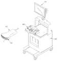
도 1은 초음파 영상 장치의 일 실시예에 따른 사시도이다.
도 2는 초음파 프로브의 일 실시예에 따른 단면도이다.
도 3은 복수 차원 배열 트랜스듀서의 다양한 일례에 따른 사시도 및 평면도다.
도 4는 복수 차원 배열 트랜스듀서를 포함하는 프로브의 일 실시예에 따른 정면도이다.
도 5는 트랜스듀서 내의 복수의 진동자를 그룹화한 일 실시예를 도시한 도면이다.
도 6은 다중 초점을 가지고 초음파 신호를 송신하는 방법의 일 실시예를 설명하기 위한 도면이다.
도 7은 초점 거리에 따라 서로 다른 주파수의 초음파 신호를 송신하는 방법의 일 실시예를 설명하기 위한 도면이다.
도 8은 cMUT에 의한 해상력을 설명하기 위한 도면이다.
도 9는 조절부가 포함된 프로브의 일 실시예에 따른 사시도이다.
도 10은 초음파 영상 장치의 일 실시예에 따른 블럭도이다.
도 11은 초음파 영상 장치 내 제어부의 일 실시예에 따른 블럭도이다.
도 12는 초음파 영상 장치에 의해 초점 거리에 따른 각각의 영상과 다중 초점 초음파 영상의 획득을 보여주는 도면이다.
도 13은 초음파 영상 장치의 제어 방법의 일 실시예를 도시한 순서도이다.1 is a perspective view of an ultrasound imaging apparatus according to an embodiment of the present invention.
2 is a cross-sectional view of one embodiment of an ultrasonic probe.
3 is a perspective view and a plan view of various examples of a multi-dimensional array transducer.
4 is a front view according to one embodiment of a probe including a multi-dimensional array transducer.
5 is a diagram showing an embodiment in which a plurality of vibrators in a transducer are grouped.
6 is a diagram for explaining an embodiment of a method of transmitting ultrasound signals with multiple foci.
7 is a view for explaining an embodiment of a method of transmitting ultrasound signals of different frequencies according to a focal distance.
FIG. 8 is a diagram for explaining the resolution by the cMUT.
9 is a perspective view according to an embodiment of the probe including the adjustment portion.
10 is a block diagram of an ultrasound imaging apparatus according to an embodiment of the present invention.
11 is a block diagram according to an embodiment of the control unit in the ultrasound imaging apparatus.
12 is a view showing acquisition of each image and a multi-focus ultrasound image according to the focal distance by the ultrasound imaging apparatus.
13 is a flowchart showing an embodiment of a control method of an ultrasound imaging apparatus.
이하 첨부된 도면을 참조하여 초음파 영상 장치 및 초음파 영상 장치의 제어 방법을 후술된 실시예들에 따라 상세하게 설명하도록 한다.Hereinafter, a method of controlling an ultrasound imaging apparatus and an ultrasound imaging apparatus will be described in detail with reference to the accompanying drawings.
도 1은 초음파 영상 장치의 일 실시예에 따른 사시도이다.1 is a perspective view of an ultrasound imaging apparatus according to an embodiment of the present invention.
도 1에 도시한 바와 같이 초음파 영상 장치는 프로브(100), 본체(300), 입력부(400), 디스플레이부(140)을 포함할 수 있다.As shown in FIG. 1, the ultrasound imaging apparatus may include a
프로브(100)에는 케이블의 일단이 연결되며, 케이블의 타단에는 수 커넥터(male connector; 미도시)가 연결될 수 있다. 케이블의 타단에 연결된 수 커넥터는 본체(300)의 암 커넥터(female connector; 미도시)와 물리적으로 결합할 수 있다.One end of the cable is connected to the
프로브(100)는 대상체의 피검 부위에 대한 초음파 영상을 얻기 위해 초음파 신호를 대상체로 송신하고, 대상체로부터 반사되어 온 에코(echo) 신호(초음파 신호)를 수신할 수 있다. 여기서 대상체는 인간이나 동물의 생체, 또는 혈관, 뼈, 근육 등과 같은 생체 내 조직일 수도 있으나 이에 한정되지는 않는다.The
프로브(100)는 대상체와 직접적으로 접촉될 수도 있고, 대상체와 접촉되지 않는 외부에서 초음파 신호를 송수신할 수도 있다. 예를 들어, 태아(피검 부위)를 검사하고자 할 때는 산모의 복부(대상체)와 직접적으로 접촉되지만, 간에 있는 종양(피검 부위)을 검사하고자 할 때는 프로브(100)가 환자의 간(대상체)과 직접적으로 접촉되는 것이 아닌 환자의 복부에 접촉을 가하는 것이다.The
본체(300)는 초음파 영상 장치의 주요 구성요소 예를 들어, 구동부(도 10의 120)를 수납할 수도 있다. 검사자가 초음파 진단 명령을 입력하는 경우, 구동부(120)는 구동 신호를 생성하여 프로브(100)로 전송할 수 있다.The
본체(300)에는 하나 이상의 암 커넥터(female connector; 미도시)가 구비될 수 있으며, 케이블과 연결된 수 커넥터(male connector; 미도시)와 물리적으로 결합되어 본체(300)와 프로브(100)가 상호간에 발생한 신호를 서로 송수신 할 수 있도록 한다. 예를 들어, 구동부(130)에 의해 생성된 구동 신호는 본체(300)의 암 커넥터와 연결된 수 커넥터 및 케이블을 거쳐 프로브(100)로 전송될 수 있다.The
또한, 본체(300)의 하부에는 초음파 영상 장치를 특정 장소에 고정시키거나, 특정 방향으로 이동시킬 수 있는 복수의 캐스터(caster)가 구비될 수도 있다.In addition, a plurality of caster which can fix the ultrasound imaging device in a specific place or move the ultrasound imaging device in a specific direction may be provided under the
입력부(400)는 초음파 영상 장치의 동작과 관련된 명령을 입력 받을수 있는 부분이다. 예를 들어, 초음파 진단 시작 명령이나, 프로브(100)에서 송신하는 초음파 신호의 주파수 대역 등을 입력 받을 수 있다. 입력부(400)에서 입력 받은 명령은 유선 통신이나 무선 통신을 통해 본체(300)로 전송될 수 있다.The
입력부(400)의 구성에 있어, 스위치, 키보드, 트랙볼, 터치 스크린중 적어도 하나를 포함할 수 있으나 이에 한정되지는 않는다.The
입력부(400)는 도 1에서와 같이 본체(300)의 상부에 위치할 수도 있으나, 풋 스위치(foot switch) 및 풋 페달(foot pedal) 등이 구비되어 본체(300)의 하부에 마련될 수도 있다.1, the
입력부(400)의 주변에는 프로브(100)를 거치하기 위한 프로브 홀더가 하나 이상 구비될 수 있다. 따라서 검사자는 초음파 영상 장치를 사용하지 않을 때, 프로브 홀더에 프로브(100)를 거치하여 보관할 수 있다.At least one probe holder for mounting the
디스플레이부(140)는 초음파 진단 과정에서 얻어진 초음파 영상을 화면에 표시할 수 있으며, 도 1에서와 같이 본체(100)와 결합되어 장착될 수 있으나, 본체(100)와 분리 가능하도록 구현될 수도 있다.The
디스플레이부(140)는, 도 1에 도시하지는 않았으나, 초음파 영상 장치의 동작과 관련된 어플리케이션(예를 들면, 초음파 진단에 필요한 메뉴나 안내 사항)을 디스플레이하는 별도의 서브 디스플레이부를 포함할 수 있다.Although not shown in FIG. 1, the
디스플레이부(140)는 브라운관(Cathod Ray Tube: CRT)이나, 액정 표시 패널(Liquid Crystal Display: LCD) 등으로 적용할 수 있으나 이에 한정되지는 않는다.The
다음으로 프로브(100)에 대하여 더욱 구체적으로 설명하기로 하며, 이를 위해 도 2 내지 도 9을 참조하기로 한다.Next, the
도 2는 초음파 프로브의 일 실시예에 따른 단면도이다.2 is a cross-sectional view of one embodiment of an ultrasonic probe.
도 2를 참조하면, 프로브(100)는 복수의 진동자(piezoelectric element; E)로 형성되어진 트랜스듀서(transducer; 105)와, 트랜스듀서의 전면에 배치되어진 정합층(matching layer; 107a 및 107b)과, 트랜스듀서의 후방에 배열되어진 흡음층(backing materials; 108a 및 108b)을 포함할 수 있다.2, the
트랜스듀서(105)는 전기 신호와 초음파 신호를 상호 변환시키는 역할을 한다. 먼저 외부 전원 또는 내부 전원(예를 들면, 배터리)으로부터 프로브(100)가 전류을 공급받으면, 트랜스듀서의 복수의 진동자(E)가 진동함으로써 초음파를 생성하고, 생성된 초음파가 외부의 대상체로 조사된다. 조사된 초음파는 대상체에서 반사되고, 반사되어 돌아오는 에코 초음파를 다시 복수의 진동자(E)가 수신한다. 수신된 에코 초음파에 따라 복수의 진동자(E)가 진동하면서 진동 주파수에 대응하는 주파수의 전류를 생성한다.The
정합층(107a, 107b)은 트랜스듀서에서 발생된 초음파가 대상체에 최대한 전달될 수 있도록 또는 대상체로부터 되돌아오는 에코 초음파가 최대한 트랜스듀서에 전달될 수 있도록, 트랜스듀서(105)와 대상체 사이의 음향 임피던스 차이를 감소시키는 역할을 한다. 도 2에서와 같이 정합층이 복수의 층을 포함할 경우 음향 임피던스의 차이를 단계적으로 감소시킬 수 있다.The matching layers 107a and 107b are formed so that the acoustic impedance between the
흡음층(108a 및 108b)은 초음파를 흡수할 수 있는 재질로 형성되어, 초음파가 트랜스듀서(105)의 후방으로 진행되는 것을 차단함으로써 영상의 왜곡이 발생하는 것을 방지할 수 있다. 흡음층은 초음파의 차단효과를 향상시키기 위해 복수의 층으로 제작될 수 있다.The sound-absorbing
도 3은 복수 차원 배열 트랜스듀서의 다양한 일례에 따른 사시도 및 평면도이며, 도 4는 복수 차원 배열 트랜스듀서를 포함하는 프로브의 일 실시예에 따른 정면도이다.3 is a perspective view and plan view, according to various examples, of a multi-dimensional array transducer, and FIG. 4 is a front view, in accordance with one embodiment, of a probe including a multi-dimensional array transducer.
트랜스듀서(105)는 2차원 이상, 즉 복수 차원 배열 트랜스듀서로서 복수의 진동자의 배열에 의해 다양한 형상으로 형성될 수 있다.The
예를 들어, 도 3에 도시된 바와 같이 초음파 진행 방향을 축방향(axial direction: A), 초음파 진행 방행과 수직한 방향을 측방향(lateral direction: L), 축방향과 측방향이 이루는 평면을 기준으로 좌우 방향을 방위각 방향(azimuth direction: Z)이라 할 때, 복수의 진동자(E)가 축방향(A)으로 돌출되게 배열되어 전체적으로 볼록한 형상의 트랜스듀서(105)가 형성될 수 있다(도 3의 (a)). 또한, 복수의 진동자(E)가 볼록 형상과 오목 형상이 조합된 물결 형상의 트랜스듀서(105)를 구비하도록 배열될 수도 있을 것이다(도 3의 (b)).For example, as shown in FIG. 3, the direction of the ultrasonic wave propagates in the axial direction (A), the direction perpendicular to the ultrasonic propagation direction is the lateral direction (L) A plurality of
나아가, 평면도 도 3의 (c)에서 보듯이, 도 3의 (a)와 같은 배열이 축방향(A)으로 중첩적으로 형성되는 것도 가능하다.Further, as shown in the plan view of FIG. 3 (c), it is also possible that the arrangement as shown in FIG. 3 (a) is formed in an overlapping manner in the axial direction A.
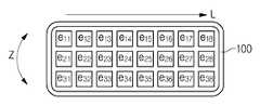
이와 같이 트랜스듀서(105)는 다양한 형태로 형성될 수 있으나, 프로브(100)의 정면에서 바라보았을 때는 복수의 진동자가 2차원 배열을 가지는 것으로 한다. 따라서, 프로브(100)의 정면에서 트랜스듀서(105)가 측방향(L)으로 m개, 방위각 방향(Z)으로 n개의 복수의 진동자(E)로 구성된다고 할 때, m≥2 이고 n≥2 인 것이다.In this way, the
예를 들어, 복수의 진동자 e11, e12, …, e18, e21, e22,…, e28, e31, e32, …, e38를 배치할 때, 도 4에서와 같이 측방향(L)으로 8개의 진동자, 방위각 방향(Z)으로 3개의 진동자가 배열되도록 할 수 있다.For example, a plurality of vibrators e11, e12, ... , e18, e21, e22, ... , e28, e31, e32, ... and e38, eight vibrators in the lateral direction L and three vibrators in the azimuth direction Z can be arranged as shown in Fig.
도 5는 트랜스듀서 내의 복수의 진동자를 그룹화한 일 실시예를 도시한 도면이다.5 is a diagram showing an embodiment in which a plurality of vibrators in a transducer are grouped.
위에서 상술한 트랜스듀서(105)는 대상체의 피검 부위나 진동자의 종류 등에 따라 필요한 복수개의 초점을 갖는다. 따라서 주어진 초점에 초음파 신호를 송신하는 진동자도 초점의 개수에 대응하여 복수개의 그룹으로 그룹화되어야 하는 것이다.The above-described
도 5는 복수의 진동자를 그룹화하는 방법을 설명하기 위해 도 4에 도시된 프로브(100)의 정면에서 복수의 진동자만 측방향(L)을 기준축으로 하여 90ㅀ 회전시켜 시각화한 것일 뿐, 앞에서 설명한 배열이나 배열 방향의 실질적인 변화는 없는 것으로 한다.5 is a diagram illustrating a method of grouping a plurality of vibrators by visualizing the front side of the
그룹화 방법의 일 실시예로 도 5에서와 같이, 측방향(L)의 복수의 진동자끼리 그룹화 할 수 있다. 즉, e11, e12, …, e18 의 진동자를 제 1그룹(s11), e21, e22,…, e28 의 진동자를 제 2그룹■s12), e31, e32, …, e38 의 진동자를 제 3그룹■s13)으로 분류할 수 있다.In an embodiment of the grouping method, as shown in Fig. 5, a plurality of oscillators in the lateral direction L can be grouped. That is, e11, e12, ... , the oscillator of e18 is referred to as a first group (s11), e21, e22, ... , the oscillator of e28 is referred to as a second group s12), e31, e32, ... , and the oscillator of e38 is classified into the third group s13).
그룹화 방법의 또 다른 실시예로, 방위각 방향(Z)의 복수의 진동자끼리 그룹화 하는 것도 가능하다. 즉, 도 5에서 e11, e21, e31 의 진동자를 제 1그룹, e12, e22, e32 의 진동자를 제 2그룹, 계속 나아가 e18, e28, e38 의 진동자를 제 8그룹이라 하여 총 8개의 그룹으로 분류할 수도 있다.As another embodiment of the grouping method, it is also possible to group a plurality of oscillators in the azimuth direction Z. Fig. In Fig. 5, the vibrators of e11, e21 and e31 are classified as the first group, the vibrators of e12, e22 and e32 as the second group, and the vibrators of e18, e28 and e38 are further classified into the eighth group You may.
위와 같이 분류한 진동자를 복수의 진동자 그룹(도 5에서는, s11, s12, s13를 의미한다)이라 칭하며, 프로브(100)가 복수의 진동자 그룹에 의해 어떻게 초음파 신호를 송신하는지 그 방법과 관련하여 설명하도록 한다.The above-described oscillator is referred to as a plurality of oscillator groups (s11, s12 and s13 in FIG. 5), and a description is given of how the
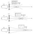
도 6은 다중 초점을 가지고 초음파 신호를 송신하는 방법의 일 실시예를 설명하기 위한 도면이며, 도 7은 초점 거리에 따라 서로 다른 주파수의 초음파 신호를 송신하는 방법의 일 실시예를 설명하기 위한 도면이다.FIG. 6 is a view for explaining an embodiment of a method of transmitting an ultrasonic signal with multiple focal points. FIG. 7 is a view for explaining an embodiment of a method of transmitting ultrasonic signals of different frequencies according to a focal length. to be.
복수의 진동자 그룹이 초음파 신호를 송신하기 위해서는 초점 설정이 선행되어야 하는데, 그룹간에 초점 거리를 달리하도록 설정하되, 분해능의 유효성을 고려한다.In order for a plurality of groups of vibrators to transmit ultrasound signals, the focus setting must be preceded. The focus distance is set to be different among the groups, and the validity of the resolution is considered.
첫째로 그룹간에 초점 거리를 달리하도록 초점을 설정한다. 즉, 각각의 진동자 그룹이 서로 다른 초점 거리를 가짐에 따라 그룹간에 중복되는 초점 거리가 없는 것으로 한다는 것이다. 여기서 초점 거리란, 각 진동자 그룹의 중심에서부터 초점면까지의 수직 거리이다.First, focus is set so that the focal distances between the groups are different. That is, as each group of oscillators has different focal lengths, there is no overlapping focal length between the groups. Here, the focal distance is the vertical distance from the center of each group of vibrators to the focal plane.
예를 들어, 도 5에서 설명한 제 1그룹(s11)은 근거리 초점, 제 2그룹(s12)은 중거리 초점, 제 3그룹은(s13)은 원거리 초점을 갖는 것으로 하여 그룹 사이에 초점 거리를 서로 달리할 수 있다.For example, it is assumed that the first group s11 described in FIG. 5 has the near focus, the second group s12 has the medium focus, and the third group has the far focus, can do.
또한, 제 1그룹(s11)이 갖는 근거리 초점을 초점 1로, 제 2그룹(s12)이 갖는 중거리 초점을 초점 2로, 제 3그룹(s11)이 갖는 원거리 초점을 초점 3으로 하여 그룹 사이에는 초점 거리를 달리하되, 각각의 그룹 안에 있는 진동자들끼리는 같은 초점 거리를 갖는 것으로 할 수도 있다.It is also possible to set the short focus of the first group s11 to focus 1, the middle focus of the second group s12 to focus 2 and the far focus of the third group s11 to focus 3, The focal lengths of the groups may be different from each other.
둘째로 초점 설정 시 분해능의 유효성을 고려하도록 한다.Second, consider the effectiveness of the resolution when setting the focus.
도 6를 참조하면, 진동자로부터 발생한 초음파는 일정거리까지 초음파 프로브(100)의 축방향으로 진행하다 일정거리 이후에서는 발산하는데, 초음파가 발산되기 전까지의 영역을 근거리 음장(near field; x), 발산하는 영역을 원거리 음장(far field; y)이라 하면, 근거리 음장 영역(x)에서 초음파 영상의 분해능이 유효하다.6, the ultrasonic waves generated from the vibrator travel in a direction of the axis of the
특히 근거리 음장 영역(x)의 끝부분에서 분해능이 뛰어나므로, 대상체의 피검 부위가 근거리 음장 영역(x)의 끝부분에 모두 위치하도록 진동자 그룹들의 초점을 설정한다.Especially, since the resolution is excellent at the end portion of the near field sound field region (x), the focus of the group of the vibrators is set so that the portion to be examined of the object is located at the end portion of the near field region x.
위와 같은 초점 설정에 따라 초음파 신호를 송신함에 있어서, 복수의 진동자 그룹이 초점 거리만을 서로 달리하여, 동시에 대상체로 초음파 신호를 송신하는 것으로 할 수 있다.In transmitting an ultrasonic signal in accordance with the above-described focus setting, it is possible to transmit ultrasonic signals to a target object at the same time, with a plurality of groups of oscillators having different focal distances from each other.
도 6를 참조하면, 복수의 진동자 그룹(s11, s12, s13)에서 제 1그룹(s11)은 초점 1이라는 근거리 초점을, 제 2그룹(s12)은 초점 2라는 중거리 초점을, 제 3그룹(s13)은 초점 3이라는 원거리 초점으로 서로 다른 초점 거리를 가지고, 제 1그룹(s11), 제 2 그룹(s12), 제 3그룹(s13)이 동시에 초음파를 대상체로 송신할 수 있다.6, the first group s11 in the plurality of vibrator groups s11, s12, and s13 has a near focus of
또한, 서로 다른 초점 거리를 가지는 복수개의 진동자 그룹이, 초점 거리에 따라 서로 다른 주파수의 초음파 신호를, 동시에 대상체로 송신하는 것으로 할 수도 있다. 이 때 초점 거리와 초점 거리에 대응하는 송신 주파수는 반비례 관계이다.It is also possible that a plurality of groups of vibrators having different focal lengths transmit ultrasound signals of different frequencies according to the focal distance to a target object at the same time. At this time, the focal distance and the transmission frequency corresponding to the focal distance are in inverse proportion.
예를 들면, 도 7에서와 같이, 근거리 초점(초점 1)을 가지는 제 1그룹(s11)은 고주파 신호를, 중거리 초점(초점 2)을 가지는 제 2그룹(s12)은 중간 주파수 신호를, 원거리 초점(초점 3)을 가지는 제 3 그룹(s13)은 저주파 신호의 초음파를 대상체로 송신하되, 제 1그룹(s11), 제 2 그룹(s12), 제 3그룹(s13)은 모두 동시에 송신하는 것으로 할 수 있다.For example, as shown in Fig. 7, the first group s11 having the short focus (focus 1) has the high frequency signal, the second group s12 having the medium focus (focus 2) The third group s13 having the focus (focus 3) transmits the ultrasonic waves of the low-frequency signals to the object, and the first group s11, the second group s12 and the third group s13 simultaneously transmit can do.
이와 같이 초점 거리에 따라 주파수를 달리하는 이유는 이하에서 설명하는 감쇄량 및 분해능과 관련이 있다.The reasons for varying the frequency depending on the focal length are related to the amount of attenuation and resolution described below.
파동의 일종인 초음파는 반사와 산란, 흡수 등의 현상을 일으키며, 이 때문에 대상체의 피검 부위까지의 거리가 증가함에 따라 초음파 신호의 세기가 점점 감소하는 감쇄가 일어난다. 주파수가 높을수록 감쇄량은 많아지며, 따라서 고주파를 사용하는 경우 원거리까지 초음파의 투과가 이루어지지 않는다.Ultrasonic waves, which are a kind of waves, cause phenomena such as reflection, scattering, and absorption. As a result, the intensity of the ultrasonic signal is gradually decreased as the distance to the target portion of the object increases. The higher the frequency, the greater the amount of attenuation, and thus the transmission of ultrasound to a remote location is not achieved when high frequencies are used.
한편 영상 표시 장치에서 서로 다른 두 물체를 식별해 낼 수 있는 능력인 초음파의 분해능을 크게 초음파의 진행방향으로 나란히 있는 두 물체를 구별하는 능력인 축방향 분해능(axial resolution)과, 초음파 진행방향에 수직으로 나란히 있는 두 물체를 구별하는 능력인 측방향 분해능(lateral resolution)으로 나누면, 주파수가 높을수록 분해능, 특히 축방향의 분해능(axial resolution)을 향상시킬 수 있다.On the other hand, the axial resolution, which is the ability to distinguish between the two objects that are parallel to the direction of ultrasonic wave propagation, is the ability to identify two different objects in the image display device, Divided by the lateral resolution, which is the ability to distinguish two objects side by side, the higher the frequency, the better the resolution, especially the axial resolution.
따라서, 근거리 초점의 영역에서는 초점 거리에 대비하여 감쇄량은 크게 문제되지 않을 것이므로 분해능을 향상시키는 고주파의 신호를 송신하고, 원거리 초점의 영역에서는 분해능의 저하를 감안하더라도 초음파가 원거리까지 투과될 수 있도록 감쇄량이 적은 저주파의 신호를 송신하여 고화질의 다중 초점 초음파 영상을 획득할 수 있도록 하는 것이다.Therefore, in the region of near focus, the attenuation amount will not be a big problem as compared with the focal distance. Therefore, a high frequency signal for improving the resolution is transmitted, and even in consideration of the degradation of resolution in the range of the far focal distance, So that a high-quality multi-focus ultrasound image can be obtained.
그러므로, 도 7에서는, 근거리 초점(초점 1)을 가지는 제 1그룹(s11)은 분해능을 향상시키는 고주파 신호를, 원거리 초점(초점 3)을 가지는 제 3 그룹(s13)은 감쇄량이 적은 저주파 신호의 초음파를 대상체로 송신하는 것으로 하여, 복수의 진동자 그룹이 서로 다른 초점 거리를 갖되, 초점 거리와 반비례 관계가 되는 서로 다른 주파수의 초음파 신호를 송신하게 한 것이다.Therefore, in FIG. 7, the first group s11 having the near focus (focus 1) has the high-frequency signal for improving resolution and the third group s13 having the far focus (focus 3) has the low- The ultrasonic waves are transmitted to the object so that ultrasonic signals of different frequencies having different focal distances but in inverse proportion to the focal length are transmitted.
이상으로 프로브(100)의 초음파 송신 방법의 실시예들을 설명하였다.Embodiments of the ultrasonic transmission method of the
이때 사용될 수 있는 프로브(100) 내 트랜스듀서(105)는 자성체의 자왜효과를 이용하는 자왜 초음파 트랜스듀서(Magnetostrictive Ultrasound Transducer)나, 미세 가동된 수백 또는 수천 개의 박막의 진동을 이용하여 초음파 신호를 송수신하는 정전용량형 미세가공 초음파 트랜스듀서(Capacitive Micromachined Ultrasonic Transducer: cMUT, 이하 cMUT라 칭함)나, 압전물질의 압전효과를 이용한 압전 초음파 트랜스듀서(Piezoelectric Ultrasonic Transducer) 등이 있을 수 있다. 그러나 상술한 예에 한정되는 것은 아니며, 당업계에 알려져 있는 임의의 다른 형태의 트랜스듀서로 구현될 수 있음은 물론이다.The
다만, 고집적화 기술을 사용하여 초소형 트랜스듀서의 제작을 가능하게 한 cMUT가 크게 주목 받고 있으므로, 이에 대해 도 8를 참조하여 좀 더 살펴보기로 한다.However, since the cMUT capable of manufacturing the ultra-small transducer using the high integration technology has received a great deal of attention, a more detailed description will be given with reference to FIG.
도 8은 cMUT에 의한 해상력을 설명하기 위한 도면이다.FIG. 8 is a diagram for explaining the resolution by the cMUT.
대상체의 피검 부위가 결과 영상에 반영되기 위해서는 대상체의 피검 부위가 복수의 진동자 그룹의 초점에 위치하여야 한다.In order for the target portion of the target object to be reflected in the resultant image, the target portion of the target object should be located at the focal point of the plurality of groups of the vibrator.
예를 들어, 도 8의 (a)와 같은 경우에는, 방위각(azimuth) 방향으로 3개의 진동자 그룹(s11, s12, s13)이 존재하고 진동자 그룹 1(s11)은 초점 1, 그룹 2(s12)는 초점 2, 그룹 3(s13)은 초점 3으로 각각 근거리, 중거리, 원거리의 초점을 갖는다고 하면, 최소한 피검 부위가 원거리 초점인 초점 3에 위치해야만 영상에서 표현되어질 수 있다. 따라서, 피검 부위가 근거리 또는 중거리 초점에 위치하지 않는다면, 피검 부위의 크기가 적어도 방위각 방향의 3개의 진동자 크기보다 커야 한다.For example, in the case of FIG. 8A, three vibrator groups s11, s12 and s13 exist in the azimuth direction, and the vibrator group 1 (s11) (2), and group 3 (s13) has focus at a short distance, a medium distance, and a long distance, respectively. Therefore, if the region to be examined is not located at a near or medium focus, the size of the region to be examined must be at least larger than the size of the three vibrators in the azimuth direction.
바꾸어 말하면, 도 8의 (b)에서와 같이, 대상체의 피검 부위가 근거리 또는 중거리 초점에 위치하지 않으며, 피검 부위의 크기도 방위각(azimuth) 방향으로 약 2개의 진동자 크기를 가진다면, 결국 피검 부위는 결과 영상에서 표현되지 않게 되는 것이다.In other words, as shown in FIG. 8 (b), if the region to be examined of the object is not located in the near or middle focal point, and the size of the region to be examined has about two vibrator sizes in the azimuth direction, Is not expressed in the resultant image.
그러나, cMUT에 포함된 진동자는 지름이 약 30ㅅm(마이크로미터: 100만분의 1m)이고 두께는 약 3,000~7,000ㅕ(옹스트롱: 100억분의 1m)으로 그 크기가 매우 작아, 피검 부위가 결과 영상에서 표현되지 않는 오차가 발생하더라도 그 오차의 크기 또한 무시할 수 있을 정도이다. 따라서 cMUT의 사용으로 고해상도의 영상을 획득할 수 있게 된다.However, the vibrator included in the cMUT has a diameter of about 30 mm (micrometer: 1 millionth of a meter) and a thickness of about 3,000 to 7,000 mm Even if an error that is not represented in the result image occurs, the magnitude of the error can be ignored. Therefore, it is possible to acquire a high resolution image by using cMUT.
도 9는 조절부가 포함된 프로브의 일 실시예에 따른 사시도이다.9 is a perspective view according to an embodiment of the probe including the adjustment portion.
각각의 진동자는 일정한 주파수를 가지고 대상체에 초음파 신호를 송신하고 에코 신호를 수신하는데, 이 때 대상체의 매질의 종류 및 구조 등에 따라 초음파의 전파 속도, 감쇄도 등이 달라질 수 있다. 따라서, 대상체의 매질에 대응하여 진동자가 송신하는 초음파 신호의 주파수를 조절함으로써 얻고자 하는 영상을 더욱 고화질화 시킬 수 있다. 여기서 대상체의 매질은 혈액, 지방, 신경, 근육, 뼈 등이 될 수 있으나 이에 한정되지는 않는다.Each oscillator transmits an ultrasonic signal to a target object with a predetermined frequency and receives an echo signal. At this time, propagation speed and attenuation of the ultrasonic wave may vary depending on the type and structure of the target medium. Therefore, by adjusting the frequency of the ultrasonic signal transmitted by the vibrator corresponding to the medium of the object, the image to be obtained can be further enhanced. The medium of the subject may be, but is not limited to, blood, fat, nerve, muscle, bone, and the like.
예를 들어, 앞에서 설명한 초음파의 감쇄 현상은 조직의 단백함량, 수분함량 등 조직의 성질에 따라 혈액, 지방, 신경, 근육, 피부, 건, 연골, 뼈의 순으로 그 감쇄도가 많아진다. 따라서, 대상체의 매질이 감쇄도가 큰 뼈인 경우, 초음파 신호의 송신 주파수를 조금 낮추고, 매질이 감쇄도가 적은 혈액의 경우, 주파수를 높이는 것과 같은 주파수 조절이 요구될 수 있는 것이다.For example, the attenuation of the ultrasonic wave described above increases in the order of blood, fat, nerve, muscle, skin, tendon, cartilage and bone depending on the nature of tissue such as protein content and moisture content. Therefore, when the medium of the object is a bone having a large degree of attenuation, it is required to adjust the frequency such that the transmission frequency of the ultrasonic signal is slightly lowered and the frequency of the blood is decreased in the case of the medium having a low attenuation.
주파수 조절의 방법에 있어서, 복수의 진동자 그룹이 대상체로 송신하는 초음파 신호의 주파수를 대상체의 매질에 따라 전체적으로 높이거나 낮출 수 있다. 또한, 초음파 신호의 송신 주파수를 복수의 진동자 그룹의 그룹별로 각각 조절할 수도 있을 것이다.In the frequency adjustment method, the frequency of the ultrasonic signal transmitted by the plurality of groups of vibrator to the object can be increased or decreased as a whole according to the medium of the object. In addition, the transmission frequency of the ultrasonic signal may be adjusted for each group of a plurality of groups of the vibrators.
주파수 대역의 조절을 위한 조절부(200)의 위치에 따라, 조절부(200)를 도 9에서와 같이 프로브(100)에 포함시킬 수 있고, 프로브(100) 외부(예를 들어, 제어부(도 10의 110))에 포함시키는 것 또한 가능하다.9, the
조절부(200)의 구동 방식에 따라, 도 9에서와 같이 회전식이 될 수도 있고, 버튼식이 될 수도 있으나 그 방식의 제한은 없다.Depending on the driving method of the regulating
이상으로 초음파 영상 장치의 프로브(100) 및 프로브(100)의 역할에 대해 설명하였고, 이하에서는 초음파 영상 장치의 본체의 구성을 자세히 설명하도록 한다.The functions of the
도 10은 초음파 영상 장치의 일 실시예에 따른 블럭도이다.10 is a block diagram of an ultrasound imaging apparatus according to an embodiment of the present invention.
도 10을 참조하면, 본체(300)는 생성된 구동 신호를 프로브(100)로 전송하고, 프로브(100)로부터 에코 신호를 수집하는 구동부(120), 구동부(120)로부터 전달 받은 에코 신호에 대응하여 영상을 생성하는 영상 처리부(130), 제어 명령 신호를 출력하거나 저장부(도 11의 112)에 데이터를 저장, 송신 주파수의 조절 등과 같은 역할을 하는 제어부(110)를 포함 할 수도 있다.10, the
구동부(120)는 송신 신호 생성부(121), 수신 신호 수집부(122) 및 빔 포밍부(150)를 포함할 수 있다.The driving
송신 신호 생성부(121)는 제어부(110)의 명령 신호에 응답하여 프로브(100)가 초음파를 대상체(ob)로 송신하도록 하는 구동 신호를 생성한다. 송신 신호 생성부(121)로부터 생성된 구동 신호는 프로브(100)로 전달된다.The transmission
수신 신호 수집부(122)는 에코 신호를 프로브(100)로부터 전달 받는다. 이 때의 에코 신호는, 프로브(100)가 대상체(ob)로부터 받은 에코 신호(초음파 신호)가 트랜스듀서(105)에 의해 전기적으로 변환된 신호를 말하며, 대상체(ob) 내의 피검 부위(t)에 대한 정보를 가지고 있다. 수신 신호 수집부(122)는 전달 받은 에코 신호를 영상 처리부(130)로 출력하는 역할도 수행할 수 있다.The reception
빔 포밍부(150)는 아날로그 신호와 디지털 신호를 상호 변환할 수 있어, 송신 신호 생성부(121)로부터 생성된 구동 신호(디지털 신호)를 아날로그 신호로 변환 또는 프로브(100)로부터 전달 받는 에코 신호(아날로그 신호)를 디지털 신호로 변환하여 프로브(100)와 구동부(120)가 소통할 수 있도록 해 준다.The
또한, 빔 포밍부(150)는 초음파가 초점에 도달하는 시간 차이 또는 초점으로부터 도달하는 시간 차이를 극복하기 위해, 진동자의 위치 및 초점을 고려하여 디지털 신호에 시간 지연을 가하는 역할을 하기도 한다.In addition, the
즉, 복수의 진동자가 동시에 초음파를 발사하는데 이 모든 초음파가 초점(focus point)에 모이도록 하는 과정을 집속(focusing)이라 하면, 초음파를 발사할 때 각 진동자에서 발생된 초음파가 초점에 도달하는 시간 차이를 극복하기 위해 적절한 순서를 정해서 발사하는 송신 집속(transmit focusing)과, 에코 초음파가 각 진동자에 도달하는 시간 차이를 극복하기 위해 적절한 시간 차이를 두어 동일한 시간에 정렬되도록 하는 수신 집속(receive focusing)의 역할을 할 수 있다.That is, when a plurality of oscillators emit ultrasonic waves at the same time and all of the ultrasonic waves are focused at a focus point, focusing is performed so that the time when the ultrasonic waves generated by the respective vibrators reach the focus when the ultrasonic waves are emitted A transmit focusing for setting an appropriate order to overcome the difference and a receive focusing for aligning at the same time with an appropriate time difference to overcome the time difference in which the echo ultrasonic waves reach each of the oscillators, Can play a role.
이러한 빔 포밍부(150)는 도 10에서와 같이 구동부(150) 내에 포함될 수도 있으나, 구동부 외부에 구비될 수도 있다. 즉, 구동부(120)와 별도로 본체(130)의 구성을 이루거나 프로브(100) 자체에 구비되어 그 역할을 수행하는 것도 가능하다.The
영상 처리부(130)는 신호 처리부(131), 영상 획득부(132) 를 포함할 수 있다.The
신호 처리부(131)는 구동부(120)로부터 출력된 에코 신호의 크기를 전체적으로 증폭시키는 전체 이득 조정(overall gain control)과정을 포함할 수 있다. 구동부(120)로부터 출력된 에코 신호는 그 크기가 작아서 실제 영상에 표현되기 어렵기 때문에, 영상 생성의 선행 과정으로서 전체 이득 조정(overall gain control)과정이 이루어지는 것이다. 이 때의 에코 신호는 빔 포밍부(150)에 의하여 디지털화된 신호이다.The
신호 처리부(131)는, 대상체(ob)의 매질 내에서 초음파의 감쇄 현상이 일어나므로, 이를 보완하여 피검 부위의 거리에 비례하여 에코 신호을 증가시키는 TCG(Time gain compensation)와 같은 과정을 포함할 수 있다.The
신호 처리부(131)는 필터링, 즉 에코 신호에 포함되어 있는 작은 크기의 잡음들을 제거해 신호를 선명하게 만들 수도 있다.The
영상 획득부(132)는 구동부(120)로부터 출력된 에코 신호에 대응하는, 구체적으로는 신호 처리부(131)에서 여러 처리 과정을 거친 신호에 대응하는 영상을 획득한다.The
이 때 획득되는 영상은, 복수의 진동자 그룹의 서로 다른 초점 거리에 따른 각각의 영상과, 각각의 영상들을 조합한 다중 초점 초음파 영상 중 적어도 하나일 수 있다. 여기서 다중 초점 초음파 영상이란, 기준면(여기서는 프로브의 접촉면)에서부터 목표 부위(여기서는 피검 부위)까지의 거리 또는 깊이가 단일하지 않아, 초음파 영상 장치가 복수의 초점 또는 초점 거리를 가질 때, 복수의 초점 거리에 따라 얻어진 복수의 영상들을 조합시킨 초음파 영상을 말한다.The image obtained at this time may be at least one of each image corresponding to a different focal distance of a plurality of groups of vibrators and a multi-focal ultrasound image in which respective images are combined. Here, the multi-focus ultrasound image means a case in which the distance or the depth from the reference surface (here, the contact surface of the probe) to the target region (herein, the region to be examined) is not uniform. Therefore, when the ultrasound imaging apparatus has a plurality of focal lengths or focal lengths, The ultrasound image is obtained by combining a plurality of images obtained according to the above-described method.
조합한 다중 초점 초음파 영상의 획득에 있어서, 단순히 각각의 영상들을 모두 중첩시켜 조합할 수도 있고, 초점 거리에 따라 근거리 음장 영역(near field)에 해당하는 부분적 영상만을 각각 선택한 후 중첩시켜 조합하는 등 영상을 조합시키는 방법에는 제한이 없다.In the acquisition of the combined multi-focus ultrasound image, it is possible to simply combine and superimpose each of the images, or to select a partial image corresponding to a near field region according to the focal distance, There is no limitation in the method of combining the two.
또한, 획득되는 영상은 각 픽셀(예를 들어, 2차원 영상일 경우 x좌표 및 y좌표로 표현)에 대응하여 명도값만을 가진 흑백 영상일 수도 있고, 각 픽셀에 대응하여 명도값, 채도값, 색상값을 가진 칼라 영상일 수도 있다.Also, the obtained image may be a monochrome image having only a brightness value corresponding to each pixel (for example, expressed as an x coordinate and a y coordinate in the case of a two-dimensional image), and a brightness value, a saturation value, It may be a color image having a color value.
영상 획득부(132)는 영상 데이터를 저장하기 위한 압축 과정을 더 포함할 수도 있고, 생성된 영상을 화면에 표시할 수 있도록 영상 데이터를 디스플레이부(140)로 전송할 수도 있다.The
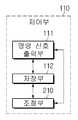
도 11은 초음파 영상 장치 내 제어부의 일 실시예에 따른 블럭도이다.11 is a block diagram according to an embodiment of the control unit in the ultrasound imaging apparatus.
제어부(110)는 명령 신호 출력부(111), 저장부(112), 조절부(210)를 포함 할 수 있다.The
명령 신호 출력부(111)는 먼저 구동부(120)로 제어 명령 신호을 출력할 수 있다.The command
명령 신호 출력부(111)는, 검사자가 초음파 진단 명령을 입력부(400)에 입력하는 경우, 초음파를 대상체(ob)로 송신하라는 명령 신호를 구동부(120)에 출력한다.When the inspector inputs the ultrasonic diagnostic command to the
또한, 명령 신호 출력부(111)는 송신할 초음파의 주파수 대역에 대한 명령 신호를 구동부(120)에 함께 출력할 수 있다. 이 때 대상체(ob)의 매질에 따라 검사자가 입력한 주파수로 명령 신호를 보낼 수도 있고, 대상체(ob)의 매질에 따라 송신할 주파수가 미리 정해져 그에 의해 자동 선택되어 명령 신호를 보낼 수도 있다.In addition, the command
명령 신호 출력부(111)는 영상 처리부(130)로 제어 명령 신호를 출력할 수 있다.The command
명령 신호 출력부(111)는 생성된 영상을 디스플레이부(140)에 표시하도록 하는 명령 신호를 영상 처리부(130)에 출력할 수 있다. 이 때 복수의 진동자 그룹의 서로 다른 초점에 따른 각각의 영상과, 각각의 영상들을 조합한 다중 초점 초음파 영상을 모두 표시하도록 명령 신호를 출력할 수도 있고, 다중 초점 초음파 영상만을 표시하도록 명령 신호를 출력할 수도 있다. 이는 검사자가 입력부(400)에서 선택하거나 미리 설정되어 있는 방법에 따른다.The command
또한, 명령 신호 출력부(111)는 화면 표시 모드에 대한 명령 신호를 영상 처리부(130)에 함께 출력할 수도 있다. 여기서 영상을 화면에 표시하는 모드는, 에코 신호의 강도를 진폭의 크기로 표시하는 A-mode, 밝기 또는 휘도로 변환시켜 표시하는 B-mode, 움직이는 피검 부위와의 거리를 시간적 변화로 표시하는 M-mode, 펄스파나 연속파를 사용하는 D-mode, 도플러 효과를 이용하여 색 영상으로 나타내는 CFM-mode 등이 있으나 이에 한정되지는 않는다. 피검 부위(t)의 위치, 크기, 형태 등에 따라 자동 선택된 표시 모드로 명령 신호를 출력하거나, 검사자의 판단에 의해 입력된 표시 모드로 명령 신호를 출력할 수 있다.In addition, the command
저장부(112)는 초음파 영상 장치의 조작을 위한 데이터나 알고리즘을 저장할 수 있다. 예를 들면, 피검 부위(t)까지의 거리 또는 대상체(ob)의 매질에 따른 송신 주파수와 같은 각종 파라미터, 영상 처리부(130)에서 생성된 영상의 압축 데이터, 영상의 픽셀 및 각 픽셀에 대응하는 명도값, 피검 부위(t)의 성질에 따른 화면 표시의 모드 등을 저장 할 수 있다. 또한, 영상을 생성하기 위한 알고리즘, 초점 거리에 따라 획득된 각각의 영상들을 조합하기 위한 알고리즘 등을 저장 할 수도 있다.The
이러한 저장부(112)는 롬(Read Only Memory: ROM), 피롬(Programmable Read Only Memory: PROM), 이피롬(Erasable Programmable Read Only Memory: EPROM), 플레시 메모리와 같은 비휘발성 메모리 소자, 또는 램(Random Access Memory: RAM)과 같은 휘발성 메모리 소자, 또는 하드 디스크, 광 디스크와 같은 저장 장치로 구현될 수 있다. 다만, 이에 한정되는 것은 아니며, 당업계에 알려져 있는 임의의 다른 형태로 구현될 수도 있다.The
조절부(210)는 입력부(400)와 명령 신호 출력부(111) 사이에 연계되어 초음파 영상 장치의 구동이나 화면 출력 등을 위한 여러가지 파라미터의 조절 기능을 할 수 있다.The
파라미터 조절의 한 예로, 대상체(ob)의 매질에 따라 송신하는 초음파 신호의 주파수를 조절할 수 있다. 즉, 입력부(400)에서 대상체(ob)의 매질을 입력받으면, 조절부(210)에서 매질의 성질을 파악하여 그에 따라 설정된 초음파의 주파수 대역을 자동 선택하여 명령 신호 출력부(111)로 전송할 수 있는 것이다. 송신 주파수의 조절의 필요성은 앞서 설명한 바 있으므로 여기서는 생략하도록 한다.As an example of the parameter adjustment, the frequency of the ultrasonic signal to be transmitted can be adjusted according to the medium of the object ob. That is, when receiving the medium of the object ob from the
주파수 선택은, 예를 들면, 복수의 진동자 그룹이 대상체(ob)로 송신하는 초음파 신호의 주파수를 대상체(ob)의 매질에 따라 일괄적으로 높이거나 낮추도록 선택되어질 수 있다. 또한, 초점 거리를 달리하는 각 진동자 그룹마다 송신할 주파수가 각각 선택되어질 수도 있다.The frequency selection can be selected, for example, to increase or decrease the frequency of the ultrasonic signal transmitted by the plurality of groups of vibrators to the object ob collectively according to the medium of the object ob. Further, frequencies to be transmitted may be selected for each group of the vibrators having different focal lengths.
전술한 파라미터 조절의 다른 예로, 조절부(210)는 입력부(400)로부터 화면상에 표시할 영상의 휘도(명도) 레벨, 크기나 방향 등을 입력받으면, 그에 맞추어 영상 데이터에 변경을 가하고 명령 신호 출력부(111)로 전송할 수 있다. 이로 인해, 검사자가 대상체(ob)의 피검 부위(t)를 관찰하고, 필요한 정보를 얻어내는 과정이 더욱 용이해진다.In another example of the parameter adjustment, when the brightness (brightness) level, size, direction, or the like of an image to be displayed on the screen is inputted from the
도 12는 위에서 상술한 초음파 영상 장치에 의하여, 초점 거리에 따른 각각의 영상과 다중 초점 초음파 영상의 획득을 보여주는 도면이다.12 is a view showing acquisition of each image and a multi-focus ultrasound image according to the focal distance by the above-described ultrasound imaging apparatus.
도 12의 (a), (b), (c)에서와 같이, 도 6에서 설명한 복수의 진동자 그룹(s11, s12, s13)이 초점 1, 초점 2, 초점 3 으로 초점 거리를 서로 달리하여 동시에 대상체로 초음파를 송신하였을 때, 그에 대응되는 영상이 도 12의 (d)에서처럼 스캔 1, 스캔 2, 스캔 3 으로 각각 출력된다.As shown in Figs. 12 (a), 12 (b) and 12 (c), the plurality of groups of oscillators s11, s12 and s13 described in Fig. 6 are focal 1, focal 2, When an ultrasonic wave is transmitted to a target object, the corresponding image is output as
초점 설정 시 고려될 요소인 근거리 음장(near field)과 관련하여 앞에서 설명하였듯, 각 진동자 그룹의 기준 초점 영역에서는 초음파 영상의 분해능이 좋으나, 초점 영역 전ㅇ후에서는 초음파 영상의 분해능이 저하된다. 따라서 도 12의 (d)에 나타난 바와 같이 각 그룹의 스캔 영상에서, 초점 영역 외 부분에서는 영상의 품질이 급격히 떨어진다.As described above with respect to the near field, which is an element to be considered in setting the focus, the resolving power of the ultrasound image is good in the reference focus region of each oscillator group, but resolution of the ultrasound image is degraded after the focus region. Therefore, as shown in (d) of FIG. 12, in the scan image of each group, the quality of the image sharply falls outside the focus area.
그러므로 서로 다른 초점 거리에 대응하여 출력된 3장의 영상(스캔 1, 스캔 2, 스캔 3)들의 조합으로 모든 영역에서 고화질화된 다중 초점 초음파 영상을 생성한다(도 12의 (e)).Therefore, a high-quality multi-focus ultrasound image is generated in all areas by combining three images (scan 1, scan 2, scan 3) output corresponding to different focal lengths (FIG.
여기서 복수의 진동자 그룹이 도 7에서 설명한 그룹 s11, s12, s13 일 때, 즉 고주파 신호를 송신하는 초점 1, 중간 주파수 신호를 송신하는 초점 2, 저주파 신호를 송신하는 초점 3으로 각각의 진동자 그룹이 초점 거리에 따라 대상체로 송신하는 주파수를 달리할 때, 더욱 고화질화된 다중 초점 초음파 영상을 획득할 수 있다.Here, when a plurality of groups of vibrators are group s11, s12, s13 described in Fig. 7, that is, each group of vibrators is divided into two groups, that is,
이상으로 초음파 영상 장치의 구성 및 각 구성의 역할을 실시예들을 바탕으로 설명하였으며, 이하에서는 주어진 순서도를 참조하여 초음파 영상 장치의 제어 방법을 살펴보기로 한다.The configuration of the ultrasound imaging apparatus and the role of each configuration have been described based on the embodiments. Hereinafter, a control method of the ultrasound imaging apparatus will be described with reference to the flowcharts given.
도 13은 초음파 영상 장치의 제어 방법의 일 실시예를 도시한 순서도이다.13 is a flowchart showing an embodiment of a control method of an ultrasound imaging apparatus.
도 13을 참조하면, 먼저 복수의 진동자 그룹이 대상체로 송신하는 초음파 신호의 주파수 대역이 자동 또는 수동으로 조절된다(s300).Referring to FIG. 13, a frequency band of an ultrasonic signal transmitted from a plurality of vibrator groups to a target object is automatically or manually adjusted (s300).
이 과정은 대상체의 매질에 따라 초음파의 전파 속도, 감쇄도 등이 달라지기 때문에 보다 고화질화된 영상을 획득하기 위한 과정으로, 복수의 진동자 그룹이 초음파 신호를 대상체로 송신하기 전 단계에서 이루어진다. 따라서 위에서와 달리 후술할 신호 출력 단계(s310) 이후, 즉 s310단계와 s320단계의 사이에서 이루어지는 것도 가능하다.Since the propagation speed and attenuation degree of the ultrasonic wave are changed depending on the medium of the object, this process is a process for acquiring a higher-quality image, and a plurality of groups of the vibrators are performed before the ultrasonic signal is transmitted to the object. Therefore, unlike the above, it is also possible to perform after the signal output step s310 to be described later, that is, between step S310 and step S320.
이 과정은 복수의 진동자 그룹이 대상체로 송신하는 초음파 신호의 주파수를 대상체의 매질에 따라 일괄적으로 조절하는 과정이거나, 초음파 신호의 송신 주파수를 복수의 진동자 그룹의 그룹별로 각각 조절하는 과정이다.This process is a process of collectively adjusting the frequency of an ultrasonic signal transmitted from a plurality of groups of vibrators to a target object according to a medium of a target object or adjusting a transmission frequency of an ultrasonic signal for each group of a plurality of vibrator groups.
이 때 대상체의 매질에 따라 검사자가 송신할 주파수를 직접 입력하여 조절할 수도 있고, 검사자는 대상체의 매질만 입력하고 이에 따라 미리 설정된 주파수 대역이 선택되어 자동 조절될 수도 있다.In this case, the frequency to be transmitted by the inspector may be directly inputted or adjusted according to the medium of the object, or the inspector may input only the medium of the object, and the preset frequency band may be selected and automatically controlled.
다음으로 제어부(도 10의 110)는 대상체로 초음파 신호를 송신하라는 제어 명령 신호를 출력한다(s310).Next, the
위 제어 명령 신호가 출력되면 구동부(도 10의 120)는 프로브(100)가 초음파를 대상체로 송신하도록 하는 구동 신호를 출력한다. 명령 신호를 받은 후에 구동 신호가 출력되므로 구동 신호가 프로브(100)의 초음파 송신에 직접적인 역할을 한다.When the control command signal is outputted, the driving
구동 신호에 응답하여, 복수의 진동자 그룹이 초음파 신호를 대상체로 송신한다(s320).In response to the drive signal, a plurality of groups of vibrators transmit ultrasound signals to the target object (s320).
이 단계에서는 복수의 진동자 그룹이 서로 다른 초점 거리를 가지고, 동시에 초음파 신호를 대상체로 송신한다. 이 때 복수의 진동자 그룹의 각각은, 동일한 초점 거리를 갖는 복수의 진동자로 이루어져 초음파 신호를 송신할 수 있다.In this step, the plurality of groups of vibrators have different focal lengths, and simultaneously transmit ultrasonic signals to the object. At this time, each of the plurality of groups of vibrators is composed of a plurality of vibrators having the same focal distance, and can transmit ultrasonic signals.
또한 서로 다른 초점 거리를 가지는 복수개의 진동자 그룹이 초점 거리에 따라 서로 다른 주파수의 초음파 신호를, 동시에 대상체로 송신할 수도 있다. 이 때의 송신 주파수는 대응되는 초점 거리와 반비례 관계이다.Also, a plurality of groups of vibrators having different focal lengths may simultaneously transmit ultrasound signals of different frequencies according to the focal distance, to the target object. The transmission frequency at this time is in inverse proportion to the corresponding focal length.
다음으로 복수의 진동자 그룹이 각 초점 거리에 따른 에코 신호를 대상체로부터 수신 받는다(s330).Next, a plurality of groups of vibrators receive the echo signals corresponding to the respective focal lengths from the object (s330).
이 때 복수의 진동자 그룹이 초점 거리에 따라 서로 다른 주파수의 초음파 신호를 대상체로 송신하였다면, 대상체로부터 수신 받게 되는 에코 신호도 주파수별로 신호를 구분하여 수신 받을 수 있다.In this case, if a plurality of groups of transducers transmit ultrasound signals of different frequencies to the target according to the focal distance, the echo signals received from the target object can also receive the signals by frequency.
예를 들어, 복수의 진동자 그룹(s11, s12, s13)이 s11은 f1의 주파수로, s12 는 f2의 주파수로, s13는 f3의 주파수로 각각 주파수를 달리하여 송신하였을 때, 수신 또한 s11은 f1의 주파수, s12는 f2의 주파수, s13는 f3의 주파수로 구별하여 수신 받게 되는 것이다.For example, when a plurality of groups of oscillators s11, s12, and s13 are transmitted at a frequency of f1, a frequency of s12, and a frequency of f3, S12 is the frequency of f2, and s13 is the frequency of f3.
다음으로 에코 신호에 대응하는 초음파 영상을 생성하는데(s340), 이를 더욱 구체적인 단계로 나누어 보면 다음과 같다.Next, an ultrasound image corresponding to the echo signal is generated (s340), which is divided into more specific steps as follows.
프로브(100)가 수신 받은 에코 신호(초음파 신호)를 트랜스듀서(105)를 통해 전기적 신호로 변환하여 출력한다. 출력되는 에코 신호는 빔 포밍부(도 10의 150)를 거치면서 디지털화되어 수집되고 영상의 생성을 위해 영상 처리부(도 10의 130)에 전달된다.The
전달 받은 에코 신호로부터 복수의 진동자 그룹의 초점 거리에 따른 각각의 영상들이 생성된다. 생성된 영상들을 조합하는 과정이 포함되어 다중 초점 초음파 영상이 생성될 수도 있다.And each image corresponding to the focal distance of the plurality of groups of vibrators is generated from the received echo signal. And a process of combining the generated images may be included to generate a multi-focus ultrasound image.
이 과정 중에 저장부(도 11의 112)에 영상 데이터가 저장될 수 있고, 이를 위한 압축 과정이 더 포함될 수도 있다.During this process, the image data may be stored in the storage unit (112 of FIG. 11), and a compression process for this may be further included.
초음파 영상의 생성 과정(s340)까지 거치면, 제어부(도 10의 110)에서 영상 표시를 위한 제어 명령 신호를 보낸다(s350).When the ultrasound image is generated up to s340, a control command signal for image display is sent from the control unit 110 (s350).
영상 표시 명령의 일 실시예로, 생성된 영상을 화면에 표시하도록 하는 명령 신호를 출력할 수 있다.In one embodiment of the video display command, a command signal for displaying the generated video on the screen may be output.
영상을 화면에 표시할지 여부를 검사자로부터 선택하도록 할 수 있으며, 검사자의 선택과 상관없이 자동으로 화면에 표시하도록 명령을 출력하는 것도 가능하다. 검사자가 선택하는 경우, 화면 표시에 동의하는 경우(①)와 달리 화면 표시에 동의하지 않는 경우에는(②) 영상을 생성한 후 바로 종료하게 된다.It is possible to select whether the image is to be displayed on the screen or not, and it is also possible to output the command so that it is automatically displayed on the screen regardless of the examiner's selection. When the examiner chooses to accept the screen display, unlike (①), if the user does not agree with the screen display (②), the image is created and ends immediately.
영상 표시 명령의 다른 실시예로, 복수의 진동자 그룹의 서로 다른 초점거리에 따른 각각의 영상과, 각각의 영상들이 조합된 다중 초점 초음파 영상을 모두 화면에 표시할지, 다중 초점 초음파 영상만을 표시할지 여부에 대해 영상 표시 명령을 출력할 수도 있다.In another embodiment of the video display command, whether each of the images according to different focal lengths of the plurality of groups of vibrators and the multi-focus ultrasound image in which the respective images are combined is displayed on the screen, only the multi-focus ultrasound image is displayed It is also possible to output a video display command for the video display command.
어떠한 영상을 화면에 표시할지에 대해 검사자로부터 선택하도록 할 수 있으며, 검사자의 선택과 상관없이 자동으로 다중 초점 초음파 영상만을 화면에 표시하도록 명령 신호를 출력할 수도 있다.It is possible to select an image to be displayed on the screen by the inspector and output a command signal so that only the multi-focus ultrasonic image is automatically displayed on the screen regardless of the inspector's selection.
영상 표시 명령의 또 다른 실시예에 따르면, 가장 기본적인 A-mode, B-mode, 심장 판막이나 복부 스캔 시 대동맥의 운동ㅇ 태아의 심음을 기록하는데 사용되는 M-mode, 혈류의 속도 및 방향을 측정하여 심장 판막에서의 혈류의 역류ㅇ 판막의 협착ㅇ 선청성 심장 질환 등의 진단에 사용되는 D-mode 및 CFM-mode 등 화면 표시의 모드에 대한 명령 신호를 출력할 수도 있다.According to another embodiment of the video display command, the most basic A-mode, B-mode, M-mode used to record heart motion of the aorta during heart valve or abdominal scan, velocity and direction of blood flow Backflow of blood flow in the heart valve. Stenosis of the valve. D-mode and CFM-mode used to diagnose the heart disease.
화면 표시의 모드에 대해 검사자로부터 선택하도록 할 수 있으며, 검사자의 선택과 상관없이 자동으로 피검 부위의 성질에 따라 미리 설정된 모드로 표시하도록 명령 신호를 출력할 수도 있다.The operator can select the mode of the screen display from the inspector and automatically output the command signal to display in the preset mode according to the property of the part to be inspected regardless of the inspector's selection.
검사자의 선택에 의해(①) 또는 자동으로 화면에 표시하도록 명령이 내려진 경우, 정해진 화면 표시의 모드에 따라 영상을 화면에 표시한다(s360).When the inspector selects (1) or automatically instructs to display on the screen, the image is displayed on the screen in accordance with the predetermined screen display mode (s360).
이상과 같이 예시된 도면을 참조로 하여, 초음파 영상 장치 및 초음파 영상 장치의 제어 방법의 실시예들을 설명하였지만, 본 발명이 속하는 기술분야에서 통상의 지식을 가진 자는 본 발명이 그 기술적 사상이나 필수적인 특징을 변경하지 않고서 다른 구체적인 형태로 실시 될 수 있다는 것을 이해할 수 있을 것이다. 그러므로 이상에서 기술한 실시예들은 모든 면에서 예시적인 것이며, 한정적이 아닌 것으로 이해해야만 한다.While the present invention has been described in connection with what is presently considered to be practical exemplary embodiments, it is to be understood that the invention is not limited to the disclosed embodiments, but, on the contrary, It will be understood that the invention may be embodied in other specific forms without departing from the spirit or scope of the invention. It is therefore to be understood that the above-described embodiments are illustrative in all aspects and not restrictive.
100 : 초음파 프로브 105 : 트랜스듀서
110 : 제어부 111 : 명령 신호 출력부
112 : 저장부 120 : 구동부
121 : 송신 신호 생성부 122 : 수신 신호 수집부
130 : 영상 처리부 131 : 신호 처리부
132 : 영상 획득부 140 : 디스플레이부
150 : 빔 포밍부 200, 210 : 조절부
300 : 본체 400 : 입력부100: Ultrasonic probe 105: Transducer
110: control unit 111: command signal output unit
112: storage unit 120:
121: transmission signal generation unit 122: reception signal collection unit
130: image processor 131:
132: Image acquisition unit 140:
150:
300: main body 400: input part
Claims (24)
Translated fromKorean상기 트랜스듀서(Transducer)와 대상체 사이의 음향 임피던스 차이를 감소시키는 정합층; 및
상기 트랜스듀서(Transducer)에서 발생한 초음파 신호가 후방으로 진행되는 것을 차단시키는 흡음층;
을 포함하되,
상기 트랜스듀서(Transducer)는, 서로 다른 초점 거리를 가지는 복수의 진동자 그룹을 포함하고, 상기 복수의 진동자 그룹은, 동시에 초음파 신호를 대상체로 송신하는 초음파 프로브(Probe).A multi-dimensional array transducer for converting an electric signal and an ultrasonic signal into each other;
A matching layer for reducing a difference in acoustic impedance between the transducer and the object; And
A sound absorbing layer for blocking an ultrasonic signal generated in the transducer from moving backward;
≪ / RTI >
The transducer includes a plurality of groups of vibrators having different focal lengths, and the plurality of groups of vibrators simultaneously transmit ultrasound signals to a target object.
상기 복수의 진동자 그룹의 각각은,
동일한 초점 거리를 가지는 복수의 진동자로 이루어지는 초음파 프로브(Probe).The method according to claim 1,
Wherein each of the plurality of groups of vibrators comprises:
An ultrasonic probe (probe) comprising a plurality of vibrators having the same focal distance.
상기 복수의 진동자 그룹은,
초점 거리에 따라 서로 다른 주파수의 초음파 신호를 동시에 대상체로 송신하는 초음파 프로브(Probe).The method according to claim 1,
Wherein the plurality of groups of vibrators comprises:
An ultrasonic probe (probe) for simultaneously transmitting ultrasound signals of different frequencies to a target according to a focal distance.
상기 트랜스듀서는, mⅹn의 2차원 배열인 복수의 진동자를 포함하고,
상기 복수의 진동자 그룹은, 횡방향의 진동자끼리 그룹화하여 m (단, m은 2이상의 자연수)개의 그룹을 형성하거나, 종방향의 진동자끼리 그룹화하여 n (단, n은 2이상의 자연수)개의 그룹을 형성하는 초음파 프로브(Probe).The method according to claim 1,
Wherein the transducer includes a plurality of vibrators that are two-dimensional arrays of m x n,
The plurality of groups of oscillators may be grouped by grouping the oscillators in the lateral direction to form m groups (where m is a natural number of 2 or more) or grouping the longitudinal oscillators so that n groups (n is a natural number of 2 or more) Ultrasonic probe to form.
송신하는 초음파 신호의 주파수 대역을 조절하기 위한 조절부
를 더 포함하는 초음파 프로브(Probe).5. The method according to any one of claims 1 to 4,
A control unit for adjusting a frequency band of an ultrasonic signal to be transmitted;
And an ultrasonic probe.
상기 초음파 프로브가 초음파 신호를 송신하도록 제어 명령 신호를 출력하는 제어부; 및
상기 에코 신호에 대응하는 영상을 생성하기 위한 영상 처리부;
를 포함하되,
상기 트랜스듀서는, 서로 다른 초점 거리를 가지는 복수의 진동자 그룹을 포함하고, 상기 복수의 진동자 그룹은, 동시에 초음파 신호를 대상체로 송신하는 초음파 영상 장치.An ultrasonic probe including a multi-dimensional array transducer for transmitting an ultrasonic signal to a target object and receiving an echo signal reflected from the target object;
A controller for outputting a control command signal to transmit the ultrasonic signal to the ultrasonic probe; And
An image processor for generating an image corresponding to the echo signal;
, ≪ / RTI &
Wherein the transducer includes a plurality of groups of vibrators having different focal lengths, and the plurality of groups of vibrators simultaneously transmit ultrasonic signals to a target object.
상기 복수의 진동자 그룹의 각각은,
동일한 초점 거리를 가지는 복수의 진동자로 이루어지는 초음파 영상 장치.The method according to claim 6,
Wherein each of the plurality of groups of vibrators comprises:
Wherein the ultrasonic imaging apparatus comprises a plurality of vibrators having the same focal distance.
상기 복수의 진동자 그룹은,
초점 거리에 따라 서로 다른 주파수의 초음파 신호를 동시에 대상체로 송신하는 초음파 영상 장치.The method according to claim 6,
Wherein the plurality of groups of vibrators comprises:
And transmits ultrasound signals of different frequencies to the object at the same time according to the focal distance.
상기 트랜스듀서는, mⅹn의 2차원 배열인 복수의 진동자를 포함하고,
상기 복수의 진동자 그룹은, 횡방향의 진동자끼리 그룹화하여 m (단, m은 2이상의 자연수)개의 그룹을 형성하거나, 종방향의 진동자끼리 그룹화하여 n (단, n은 2이상의 자연수)개의 그룹을 형성하는 초음파 영상 장치.The method according to claim 6,
Wherein the transducer includes a plurality of vibrators that are two-dimensional arrays of m x n,
The plurality of groups of oscillators may be grouped by grouping the oscillators in the lateral direction to form m groups (where m is a natural number of 2 or more) or grouping the longitudinal oscillators so that n groups (n is a natural number of 2 or more) Forming ultrasound imaging device.
상기 영상 처리부는,
초점 거리에 따른 각각의 영상들을 생성하고, 상기 초점 거리에 따라 생성된 각각의 영상들을 조합하여 다중 초점 영상을 생성하는 초음파 영상 장치.The method according to claim 6,
Wherein the image processing unit comprises:
And generates a plurality of images according to the focal lengths, and combines the images generated according to the focal length to generate a multi-focal image.
상기 영상 처리부로부터 생성된 영상을 표시하는 디스플레이부;
를 더 포함하는 초음파 영상 장치.The method according to claim 6,
A display unit for displaying an image generated from the image processing unit;
Further comprising an ultrasound imaging device.
상기 제어부는,
상기 초음파 프로브가 초음파 신호를 송신하도록 제어 명령 신호를 출력하고, 상기 영상 처리부로부터 생성된 영상의 표시를 위한 제어 명령 신호를 출력하는 초음파 영상 장치.The method according to claim 6,
Wherein,
Wherein the ultrasound probe outputs a control command signal to transmit an ultrasonic signal and outputs a control command signal for displaying an image generated from the image processing unit.
송신하는 초음파 신호의 주파수 대역을 조절하기 위한 조절부;
를 더 포함하는 초음파 영상 장치.A method according to any one of claims 6 to 12,
An adjusting unit for adjusting a frequency band of an ultrasonic signal to be transmitted;
Further comprising an ultrasound imaging device.
상기 복수의 진동자 그룹이 복수의 에코 신호를 대상체로부터 수신하는 단계;
를 포함하는 초음파 프로브(Probe)의 제어 방법.A plurality of groups of transducers having different focal lengths simultaneously transmitting ultrasound signals to a target object; And
The plurality of groups of vibrators receiving a plurality of echo signals from the object;
And controlling the ultrasonic probe.
상기 복수의 진동자 그룹의 각각은,
동일한 초점 거리를 가지는 복수의 진동자로 이루어지는 초음파 프로브(Probe)의 제어 방법.15. The method of claim 14,
Wherein each of the plurality of groups of vibrators comprises:
A method of controlling an ultrasonic probe (Probe) comprising a plurality of vibrators having the same focal distance.
서로 다른 초점 거리를 가지는 복수의 진동자 그룹이 동시에 초음파 신호를 대상체로 송신하는 단계는,
초점 거리에 따라 서로 다른 주파수의 초음파 신호를 동시에 대상체로 송신하는 단계인 초음파 프로브(Probe)의 제어 방법.15. The method of claim 14,
The step of simultaneously transmitting ultrasonic signals to a target object by a plurality of groups of vibrators having different focal lengths,
And transmitting ultrasound signals of different frequencies to the object at the same time according to the focal distance.
송신하는 초음파 신호의 주파수 대역을 조절하는 단계;
를 더 포함하는 초음파 프로브(Probe)의 제어 방법.17. The method according to any one of claims 14 to 16,
Adjusting a frequency band of an ultrasonic signal to be transmitted;
And a control unit for controlling the ultrasonic probe.
상기 복수의 진동자 그룹이 복수의 에코 신호를 대상체로부터 수신하는 단계; 및
상기 복수의 에코 신호에 대응하는 영상을 생성하는 단계;
를 포함하는 초음파 영상 장치의 제어 방법.A plurality of groups of transducers having different focal lengths simultaneously transmitting ultrasound signals to a target object;
The plurality of groups of vibrators receiving a plurality of echo signals from the object; And
Generating an image corresponding to the plurality of echo signals;
And controlling the ultrasonic imaging apparatus.
상기 복수의 진동자 그룹의 각각은,
동일한 초점 거리를 가지는 복수의 진동자로 이루어지는 초음파 영상 장치의 제어 방법.19. The method of claim 18,
Wherein each of the plurality of groups of vibrators comprises:
A method of controlling an ultrasonic imaging apparatus comprising a plurality of vibrators having the same focal distance.
서로 다른 초점 거리를 가지는 복수의 진동자 그룹이 동시에 초음파 신호를 대상체로 송신하는 단계는,
초점 거리에 따라 서로 다른 주파수의 초음파 신호를 동시에 대상체로 송신하는 단계인 초음파 영상 장치의 제어 방법.19. The method of claim 18,
The step of simultaneously transmitting ultrasonic signals to a target object by a plurality of groups of vibrators having different focal lengths,
And transmitting ultrasound signals of different frequencies to the object at the same time according to the focal distance.
상기 복수의 에코 신호에 대응하는 영상을 생성하는 단계는,
초점 거리에 따른 각각의 영상을 생성하고, 상기 초점 거리에 따라 생성된 각각의 영상들을 조합하여 다중 초점 영상을 생성하는 단계인 초음파 영상 장치의 제어 방법.19. The method of claim 18,
Wherein the step of generating an image corresponding to the plurality of echo signals comprises:
Generating a plurality of images according to the focal lengths, and combining the images generated according to the focal lengths to generate a multi-focal image.
상기 생성된 영상을 표시하는 단계;
를 더 포함하는 초음파 영상 장치의 제어 방법.19. The method of claim 18,
Displaying the generated image;
And controlling the ultrasonic imaging apparatus.
상기 생성된 영상의 표시를 위한 제어 명령 신호를 출력하는 단계;
를 더 포함하는 초음파 영상 장치의 제어 방법.19. The method of claim 18,
Outputting a control command signal for displaying the generated image;
And controlling the ultrasonic imaging apparatus.
송신하는 초음파 신호의 주파수 대역을 조절하는 단계;
를 더 포함하는 초음파 영상 장치의 제어 방법.23. The method according to any one of claims 18 to 23,
Adjusting a frequency band of an ultrasonic signal to be transmitted;
And controlling the ultrasonic imaging apparatus.
Priority Applications (2)
| Application Number | Priority Date | Filing Date | Title |
|---|---|---|---|
| KR1020130050928AKR20140132811A (en) | 2013-05-06 | 2013-05-06 | Ultrasound imaging apparatus and control method for the same |
| US14/270,920US10426436B2 (en) | 2013-05-06 | 2014-05-06 | Ultrasonic imaging apparatus and control method thereof |
Applications Claiming Priority (1)
| Application Number | Priority Date | Filing Date | Title |
|---|---|---|---|
| KR1020130050928AKR20140132811A (en) | 2013-05-06 | 2013-05-06 | Ultrasound imaging apparatus and control method for the same |
Publications (1)
| Publication Number | Publication Date |
|---|---|
| KR20140132811Atrue KR20140132811A (en) | 2014-11-19 |
Family
ID=51841780
Family Applications (1)
| Application Number | Title | Priority Date | Filing Date |
|---|---|---|---|
| KR1020130050928ACeasedKR20140132811A (en) | 2013-05-06 | 2013-05-06 | Ultrasound imaging apparatus and control method for the same |
Country Status (2)
| Country | Link |
|---|---|
| US (1) | US10426436B2 (en) |
| KR (1) | KR20140132811A (en) |
Cited By (1)
| Publication number | Priority date | Publication date | Assignee | Title |
|---|---|---|---|---|
| KR20150029417A (en)* | 2013-09-10 | 2015-03-18 | 삼성메디슨 주식회사 | Method for setting a focusing point, apparatus for setting a focusing point and ultrasonic imaging apparatus |
Families Citing this family (8)
| Publication number | Priority date | Publication date | Assignee | Title |
|---|---|---|---|---|
| US20180317888A1 (en) | 2015-11-24 | 2018-11-08 | Koninklijke Philips N.V. | Ultrasound systems with microbeamformers for different transducer arrays |
| JP7011399B2 (en)* | 2017-04-14 | 2022-01-26 | フクダ電子株式会社 | Ultrasonic diagnostic equipment and its control method |
| WO2019174984A1 (en) | 2018-03-15 | 2019-09-19 | Koninklijke Philips N.V. | Variable intraluminal ultrasound transmit pulse generation and control devices, systems, and methods |
| CN110856659A (en)* | 2018-08-07 | 2020-03-03 | 泽朴医疗技术(苏州)有限公司 | Biopsy probe visualization-enhanced ultrasound probe, ultrasound imaging system, and method of use |
| CN110575200A (en)* | 2019-09-28 | 2019-12-17 | 张海霞 | Ultrasonic examination auxiliary frame |
| CN112604191A (en)* | 2020-12-14 | 2021-04-06 | 中国科学院深圳先进技术研究院 | Multi-focus ultrasonic wave generation device and method |
| JP2022178316A (en)* | 2021-05-20 | 2022-12-02 | コニカミノルタ株式会社 | Ultrasound diagnostic equipment and program |
| US20230121319A1 (en)* | 2021-10-15 | 2023-04-20 | Tzvi Neuman | Integrated Bedside Echocardiogram Monitor |
Family Cites Families (17)
| Publication number | Priority date | Publication date | Assignee | Title |
|---|---|---|---|---|
| US4307613A (en)* | 1979-06-14 | 1981-12-29 | University Of Connecticut | Electronically focused ultrasonic transmitter |
| AU1294995A (en)* | 1993-11-29 | 1995-06-19 | Perception, Inc. | Pc based ultrasound device with virtual control user interface |
| US6104670A (en)* | 1995-03-02 | 2000-08-15 | Acuson Corporation | Ultrasonic harmonic imaging system and method |
| DE19754625C2 (en)* | 1997-12-09 | 2002-01-24 | Helvoet Pharma | Stopper for closing infusion bottles |
| JP4551524B2 (en)* | 2000-03-06 | 2010-09-29 | 株式会社東芝 | Ultrasonic probe and ultrasonic diagnostic apparatus |
| AU2002228492A1 (en) | 2001-01-05 | 2002-07-16 | Bjorn A.J. Angelsen | Annular array |
| US6537219B2 (en) | 2001-04-04 | 2003-03-25 | Koninklijke Philips Electronics N.V. | Static focus ultrasound apparatus and method |
| KR100393370B1 (en) | 2001-04-25 | 2003-07-31 | 주식회사 메디슨 | Ultrasound imaging method and apparatus using orthogonal golay codes |
| US20050148877A1 (en)* | 2003-12-17 | 2005-07-07 | Siemens Medical Solutions Usa, Inc. | Multidimensional transducer probe with different transmit and receive segments for medical ultrasound imaging |
| KR100793382B1 (en) | 2006-06-26 | 2008-01-11 | 경상대학교산학협력단 | High Speed Image Acquisition Using Ultrasonic Probes |
| JP4897370B2 (en) | 2006-06-28 | 2012-03-14 | 富士フイルム株式会社 | Ultrasonic transducer array, ultrasonic probe, ultrasonic endoscope, ultrasonic diagnostic equipment |
| JP4931611B2 (en)* | 2007-01-16 | 2012-05-16 | 株式会社日立メディコ | Ultrasonic imaging device |
| US9117439B2 (en) | 2008-03-13 | 2015-08-25 | Supersonic Imagine | Method and apparatus for ultrasound synthetic imagining |
| KR20110003057A (en) | 2009-07-03 | 2011-01-11 | 삼성전기주식회사 | Ultrasonic Probes and Ultrasonic Diagnostics |
| WO2011024074A2 (en)* | 2009-08-26 | 2011-03-03 | Insightec Ltd. | Asymmetric phased-array ultrasound transducer |
| EP2489034B1 (en)* | 2009-10-14 | 2016-11-30 | Insightec Ltd. | Mapping ultrasound transducers |
| WO2013148673A1 (en)* | 2012-03-26 | 2013-10-03 | Maui Imaging, Inc. | Systems and methods for improving ultrasound image quality by applying weighting factors |
- 2013
- 2013-05-06KRKR1020130050928Apatent/KR20140132811A/ennot_activeCeased
- 2014
- 2014-05-06USUS14/270,920patent/US10426436B2/ennot_activeExpired - Fee Related
Cited By (1)
| Publication number | Priority date | Publication date | Assignee | Title |
|---|---|---|---|---|
| KR20150029417A (en)* | 2013-09-10 | 2015-03-18 | 삼성메디슨 주식회사 | Method for setting a focusing point, apparatus for setting a focusing point and ultrasonic imaging apparatus |
Also Published As
| Publication number | Publication date |
|---|---|
| US10426436B2 (en) | 2019-10-01 |
| US20140330126A1 (en) | 2014-11-06 |
Similar Documents
| Publication | Publication Date | Title |
|---|---|---|
| KR20140132811A (en) | Ultrasound imaging apparatus and control method for the same | |
| US20180206820A1 (en) | Ultrasound apparatus and method | |
| US8323201B2 (en) | System and method for three-dimensional ultrasound imaging | |
| US7985182B2 (en) | Ultrasonic diagnostic apparatus and ultrasonic image acquiring method | |
| CN110389346B (en) | Ultrasound imaging using apparent point source transmit transducers | |
| JP7363636B2 (en) | Ultrasonic diagnostic device and method of controlling the ultrasonic diagnostic device | |
| KR20110139643A (en) | Ultrasound diagnostic device | |
| CN107028623A (en) | Material stiffness is determined using porous ultrasound | |
| KR20080093281A (en) | Ultrasound Diagnostic Probe | |
| EP3329854B1 (en) | Three-dimensional imaging ultrasonic scanning method | |
| JP2015085201A (en) | Subject information acquisition device | |
| JP7171228B2 (en) | Ultrasound diagnostic equipment and medical information processing program | |
| JP2005253751A (en) | Ultrasonic probe and ultrasonic diagnosis apparatus | |
| JP4688262B2 (en) | Ultrasonic diagnostic equipment | |
| KR20140137037A (en) | ultrasonic image processing apparatus and method | |
| JP2005342194A (en) | Ultrasonic diagnostic equipment | |
| WO2013176112A1 (en) | Ultrasonic image generating method and ultrasonic image diagnostic device | |
| JP2018089368A (en) | Ultrasonic imaging apparatus and ultrasonic monitoring apparatus | |
| JP4382382B2 (en) | Ultrasonic diagnostic apparatus and ultrasonic probe | |
| JP4095332B2 (en) | Ultrasonic diagnostic equipment | |
| CN117322908A (en) | Processing ultrasound scan data | |
| KR20150118732A (en) | ultrasonic apparatus and control method for the same | |
| JP2015006260A (en) | Ultrasonic diagnostic apparatus | |
| JP5016782B2 (en) | Ultrasonic diagnostic equipment | |
| JP2010214015A (en) | Ultrasonic probe and ultrasonograph |
Legal Events
| Date | Code | Title | Description |
|---|---|---|---|
| PA0109 | Patent application | Patent event code:PA01091R01D Comment text:Patent Application Patent event date:20130506 | |
| PG1501 | Laying open of application | ||
| A201 | Request for examination | ||
| PA0201 | Request for examination | Patent event code:PA02012R01D Patent event date:20180418 Comment text:Request for Examination of Application Patent event code:PA02011R01I Patent event date:20130506 Comment text:Patent Application | |
| E902 | Notification of reason for refusal | ||
| PE0902 | Notice of grounds for rejection | Comment text:Notification of reason for refusal Patent event date:20191126 Patent event code:PE09021S01D | |
| E601 | Decision to refuse application | ||
| PE0601 | Decision on rejection of patent | Patent event date:20200619 Comment text:Decision to Refuse Application Patent event code:PE06012S01D Patent event date:20191126 Comment text:Notification of reason for refusal Patent event code:PE06011S01I |