KR20140130543A - Method and system for condition monitoring of a group of plants - Google Patents
Method and system for condition monitoring of a group of plantsDownload PDFInfo
- Publication number
- KR20140130543A KR20140130543AKR1020147027681AKR20147027681AKR20140130543AKR 20140130543 AKR20140130543 AKR 20140130543AKR 1020147027681 AKR1020147027681 AKR 1020147027681AKR 20147027681 AKR20147027681 AKR 20147027681AKR 20140130543 AKR20140130543 AKR 20140130543A
- Authority
- KR
- South Korea
- Prior art keywords
- facility
- data
- model
- component
- monitoring
- Prior art date
- Legal status (The legal status is an assumption and is not a legal conclusion. Google has not performed a legal analysis and makes no representation as to the accuracy of the status listed.)
- Ceased
Links
- 238000012544monitoring processMethods0.000titleclaimsabstractdescription94
- 238000000034methodMethods0.000titleclaimsabstractdescription61
- 230000008569processEffects0.000claimsabstractdescription33
- 238000003860storageMethods0.000claimsabstractdescription7
- 238000013079data visualisationMethods0.000claimsabstractdescription5
- 238000012800visualizationMethods0.000claimsdescription17
- 238000005457optimizationMethods0.000claimsdescription8
- 238000004891communicationMethods0.000claimsdescription5
- 230000004044responseEffects0.000claimsdescription3
- 238000012986modificationMethods0.000claimsdescription2
- 230000004048modificationEffects0.000claimsdescription2
- 238000013479data entryMethods0.000claims1
- 230000026676system processEffects0.000claims1
- 230000014509gene expressionEffects0.000abstractdescription3
- 239000007789gasSubstances0.000description23
- 238000004458analytical methodMethods0.000description17
- 241000196324EmbryophytaSpecies0.000description13
- 238000010586diagramMethods0.000description12
- 230000036541healthEffects0.000description8
- 238000012423maintenanceMethods0.000description8
- 238000011161developmentMethods0.000description6
- 230000000694effectsEffects0.000description6
- 230000006870functionEffects0.000description6
- 238000013024troubleshootingMethods0.000description6
- 238000005259measurementMethods0.000description5
- 239000000523sampleSubstances0.000description5
- IJGRMHOSHXDMSA-UHFFFAOYSA-NAtomic nitrogenChemical compoundN#NIJGRMHOSHXDMSA-UHFFFAOYSA-N0.000description4
- 230000005540biological transmissionEffects0.000description4
- 238000004364calculation methodMethods0.000description4
- 230000007257malfunctionEffects0.000description4
- 230000015556catabolic processEffects0.000description3
- 238000004590computer programMethods0.000description3
- 238000007405data analysisMethods0.000description3
- 238000006731degradation reactionMethods0.000description3
- 238000007726management methodMethods0.000description3
- 238000004519manufacturing processMethods0.000description3
- 239000000463materialSubstances0.000description3
- 238000012545processingMethods0.000description3
- 230000006399behaviorEffects0.000description2
- 230000008901benefitEffects0.000description2
- 239000003086colorantSubstances0.000description2
- 230000007423decreaseEffects0.000description2
- 230000002950deficientEffects0.000description2
- 238000013461designMethods0.000description2
- 238000003745diagnosisMethods0.000description2
- 238000009826distributionMethods0.000description2
- 239000003949liquefied natural gasSubstances0.000description2
- 229910052757nitrogenInorganic materials0.000description2
- 239000003921oilSubstances0.000description2
- 230000009467reductionEffects0.000description2
- 230000008439repair processEffects0.000description2
- 238000007789sealingMethods0.000description2
- 238000012384transportation and deliveryMethods0.000description2
- 206010000117Abnormal behaviourDiseases0.000description1
- 239000004215Carbon black (E152)Substances0.000description1
- 230000002159abnormal effectEffects0.000description1
- 230000002776aggregationEffects0.000description1
- 238000004220aggregationMethods0.000description1
- 230000004075alterationEffects0.000description1
- 238000013473artificial intelligenceMethods0.000description1
- 238000006243chemical reactionMethods0.000description1
- 239000011248coating agentSubstances0.000description1
- 238000000576coating methodMethods0.000description1
- 238000002485combustion reactionMethods0.000description1
- 238000009833condensationMethods0.000description1
- 230000005494condensationEffects0.000description1
- 239000000356contaminantSubstances0.000description1
- 238000013523data managementMethods0.000description1
- 238000013499data modelMethods0.000description1
- 238000013500data storageMethods0.000description1
- 238000012938design processMethods0.000description1
- 238000001152differential interference contrast microscopyMethods0.000description1
- 239000000428dustSubstances0.000description1
- 238000005516engineering processMethods0.000description1
- 230000007613environmental effectEffects0.000description1
- 239000000835fiberSubstances0.000description1
- 239000012530fluidSubstances0.000description1
- 239000000446fuelSubstances0.000description1
- 229930195733hydrocarbonNatural products0.000description1
- 150000002430hydrocarbonsChemical class0.000description1
- NBZBKCUXIYYUSX-UHFFFAOYSA-Niminodiacetic acidChemical compoundOC(=O)CNCC(O)=ONBZBKCUXIYYUSX-UHFFFAOYSA-N0.000description1
- 238000010921in-depth analysisMethods0.000description1
- 238000009413insulationMethods0.000description1
- 230000002452interceptive effectEffects0.000description1
- 230000007774longtermEffects0.000description1
- 239000010687lubricating oilSubstances0.000description1
- 230000003278mimic effectEffects0.000description1
- 230000003287optical effectEffects0.000description1
- 238000011958production data acquisitionMethods0.000description1
- 238000000275quality assuranceMethods0.000description1
- 239000004065semiconductorSubstances0.000description1
- 238000000926separation methodMethods0.000description1
- 230000011664signalingEffects0.000description1
- 238000012360testing methodMethods0.000description1
- 238000012549trainingMethods0.000description1
- 238000012546transferMethods0.000description1
Images


Classifications
- G—PHYSICS
- G05—CONTROLLING; REGULATING
- G05B—CONTROL OR REGULATING SYSTEMS IN GENERAL; FUNCTIONAL ELEMENTS OF SUCH SYSTEMS; MONITORING OR TESTING ARRANGEMENTS FOR SUCH SYSTEMS OR ELEMENTS
- G05B19/00—Programme-control systems
- G05B19/02—Programme-control systems electric
- G05B19/04—Programme control other than numerical control, i.e. in sequence controllers or logic controllers
- G05B19/042—Programme control other than numerical control, i.e. in sequence controllers or logic controllers using digital processors
- G05B19/0421—Multiprocessor system
- F—MECHANICAL ENGINEERING; LIGHTING; HEATING; WEAPONS; BLASTING
- F02—COMBUSTION ENGINES; HOT-GAS OR COMBUSTION-PRODUCT ENGINE PLANTS
- F02C—GAS-TURBINE PLANTS; AIR INTAKES FOR JET-PROPULSION PLANTS; CONTROLLING FUEL SUPPLY IN AIR-BREATHING JET-PROPULSION PLANTS
- F02C7/00—Features, components parts, details or accessories, not provided for in, or of interest apart form groups F02C1/00 - F02C6/00; Air intakes for jet-propulsion plants
- G—PHYSICS
- G01—MEASURING; TESTING
- G01K—MEASURING TEMPERATURE; MEASURING QUANTITY OF HEAT; THERMALLY-SENSITIVE ELEMENTS NOT OTHERWISE PROVIDED FOR
- G01K13/00—Thermometers specially adapted for specific purposes
- G—PHYSICS
- G01—MEASURING; TESTING
- G01L—MEASURING FORCE, STRESS, TORQUE, WORK, MECHANICAL POWER, MECHANICAL EFFICIENCY, OR FLUID PRESSURE
- G01L3/00—Measuring torque, work, mechanical power, or mechanical efficiency, in general
- G01L3/02—Rotary-transmission dynamometers
- G01L3/04—Rotary-transmission dynamometers wherein the torque-transmitting element comprises a torsionally-flexible shaft
- G01L3/10—Rotary-transmission dynamometers wherein the torque-transmitting element comprises a torsionally-flexible shaft involving electric or magnetic means for indicating
- G—PHYSICS
- G01—MEASURING; TESTING
- G01M—TESTING STATIC OR DYNAMIC BALANCE OF MACHINES OR STRUCTURES; TESTING OF STRUCTURES OR APPARATUS, NOT OTHERWISE PROVIDED FOR
- G01M15/00—Testing of engines
- G01M15/14—Testing gas-turbine engines or jet-propulsion engines
- G—PHYSICS
- G05—CONTROLLING; REGULATING
- G05B—CONTROL OR REGULATING SYSTEMS IN GENERAL; FUNCTIONAL ELEMENTS OF SUCH SYSTEMS; MONITORING OR TESTING ARRANGEMENTS FOR SUCH SYSTEMS OR ELEMENTS
- G05B23/00—Testing or monitoring of control systems or parts thereof
- G05B23/02—Electric testing or monitoring
- G05B23/0205—Electric testing or monitoring by means of a monitoring system capable of detecting and responding to faults
- G05B23/0218—Electric testing or monitoring by means of a monitoring system capable of detecting and responding to faults characterised by the fault detection method dealing with either existing or incipient faults
- G05B23/0224—Process history based detection method, e.g. whereby history implies the availability of large amounts of data
- G05B23/0227—Qualitative history assessment, whereby the type of data acted upon, e.g. waveforms, images or patterns, is not relevant, e.g. rule based assessment; if-then decisions
- G05B23/0235—Qualitative history assessment, whereby the type of data acted upon, e.g. waveforms, images or patterns, is not relevant, e.g. rule based assessment; if-then decisions based on a comparison with predetermined threshold or range, e.g. "classical methods", carried out during normal operation; threshold adaptation or choice; when or how to compare with the threshold
- G—PHYSICS
- G05—CONTROLLING; REGULATING
- G05B—CONTROL OR REGULATING SYSTEMS IN GENERAL; FUNCTIONAL ELEMENTS OF SUCH SYSTEMS; MONITORING OR TESTING ARRANGEMENTS FOR SUCH SYSTEMS OR ELEMENTS
- G05B23/00—Testing or monitoring of control systems or parts thereof
- G05B23/02—Electric testing or monitoring
- G05B23/0205—Electric testing or monitoring by means of a monitoring system capable of detecting and responding to faults
- G05B23/0259—Electric testing or monitoring by means of a monitoring system capable of detecting and responding to faults characterized by the response to fault detection
- G05B23/0267—Fault communication, e.g. human machine interface [HMI]
- G05B23/0272—Presentation of monitored results, e.g. selection of status reports to be displayed; Filtering information to the user
- H—ELECTRICITY
- H04—ELECTRIC COMMUNICATION TECHNIQUE
- H04L—TRANSMISSION OF DIGITAL INFORMATION, e.g. TELEGRAPHIC COMMUNICATION
- H04L67/00—Network arrangements or protocols for supporting network services or applications
- H04L67/01—Protocols
- H04L67/10—Protocols in which an application is distributed across nodes in the network
- F—MECHANICAL ENGINEERING; LIGHTING; HEATING; WEAPONS; BLASTING
- F01—MACHINES OR ENGINES IN GENERAL; ENGINE PLANTS IN GENERAL; STEAM ENGINES
- F01D—NON-POSITIVE DISPLACEMENT MACHINES OR ENGINES, e.g. STEAM TURBINES
- F01D21/00—Shutting-down of machines or engines, e.g. in emergency; Regulating, controlling, or safety means not otherwise provided for
- F01D21/003—Arrangements for testing or measuring
- F—MECHANICAL ENGINEERING; LIGHTING; HEATING; WEAPONS; BLASTING
- F01—MACHINES OR ENGINES IN GENERAL; ENGINE PLANTS IN GENERAL; STEAM ENGINES
- F01D—NON-POSITIVE DISPLACEMENT MACHINES OR ENGINES, e.g. STEAM TURBINES
- F01D21/00—Shutting-down of machines or engines, e.g. in emergency; Regulating, controlling, or safety means not otherwise provided for
- F01D21/12—Shutting-down of machines or engines, e.g. in emergency; Regulating, controlling, or safety means not otherwise provided for responsive to temperature
- F—MECHANICAL ENGINEERING; LIGHTING; HEATING; WEAPONS; BLASTING
- F02—COMBUSTION ENGINES; HOT-GAS OR COMBUSTION-PRODUCT ENGINE PLANTS
- F02C—GAS-TURBINE PLANTS; AIR INTAKES FOR JET-PROPULSION PLANTS; CONTROLLING FUEL SUPPLY IN AIR-BREATHING JET-PROPULSION PLANTS
- F02C9/00—Controlling gas-turbine plants; Controlling fuel supply in air- breathing jet-propulsion plants
- F—MECHANICAL ENGINEERING; LIGHTING; HEATING; WEAPONS; BLASTING
- F04—POSITIVE - DISPLACEMENT MACHINES FOR LIQUIDS; PUMPS FOR LIQUIDS OR ELASTIC FLUIDS
- F04B—POSITIVE-DISPLACEMENT MACHINES FOR LIQUIDS; PUMPS
- F04B51/00—Testing machines, pumps, or pumping installations
- F—MECHANICAL ENGINEERING; LIGHTING; HEATING; WEAPONS; BLASTING
- F05—INDEXING SCHEMES RELATING TO ENGINES OR PUMPS IN VARIOUS SUBCLASSES OF CLASSES F01-F04
- F05D—INDEXING SCHEME FOR ASPECTS RELATING TO NON-POSITIVE-DISPLACEMENT MACHINES OR ENGINES, GAS-TURBINES OR JET-PROPULSION PLANTS
- F05D2260/00—Function
- F05D2260/80—Diagnostics
- G—PHYSICS
- G05—CONTROLLING; REGULATING
- G05B—CONTROL OR REGULATING SYSTEMS IN GENERAL; FUNCTIONAL ELEMENTS OF SUCH SYSTEMS; MONITORING OR TESTING ARRANGEMENTS FOR SUCH SYSTEMS OR ELEMENTS
- G05B11/00—Automatic controllers
- G05B11/01—Automatic controllers electric
- G05B11/06—Automatic controllers electric in which the output signal represents a continuous function of the deviation from the desired value, i.e. continuous controllers
- G—PHYSICS
- G05—CONTROLLING; REGULATING
- G05B—CONTROL OR REGULATING SYSTEMS IN GENERAL; FUNCTIONAL ELEMENTS OF SUCH SYSTEMS; MONITORING OR TESTING ARRANGEMENTS FOR SUCH SYSTEMS OR ELEMENTS
- G05B2219/00—Program-control systems
- G05B2219/20—Pc systems
- G05B2219/25—Pc structure of the system
- G05B2219/25315—Module, sequence from module to module, structure
- G—PHYSICS
- G05—CONTROLLING; REGULATING
- G05B—CONTROL OR REGULATING SYSTEMS IN GENERAL; FUNCTIONAL ELEMENTS OF SUCH SYSTEMS; MONITORING OR TESTING ARRANGEMENTS FOR SUCH SYSTEMS OR ELEMENTS
- G05B23/00—Testing or monitoring of control systems or parts thereof
- G05B23/02—Electric testing or monitoring
- G05B23/0205—Electric testing or monitoring by means of a monitoring system capable of detecting and responding to faults
- G05B23/0208—Electric testing or monitoring by means of a monitoring system capable of detecting and responding to faults characterized by the configuration of the monitoring system
- G05B23/0216—Human interface functionality, e.g. monitoring system providing help to the user in the selection of tests or in its configuration
- G—PHYSICS
- G05—CONTROLLING; REGULATING
- G05B—CONTROL OR REGULATING SYSTEMS IN GENERAL; FUNCTIONAL ELEMENTS OF SUCH SYSTEMS; MONITORING OR TESTING ARRANGEMENTS FOR SUCH SYSTEMS OR ELEMENTS
- G05B23/00—Testing or monitoring of control systems or parts thereof
- G05B23/02—Electric testing or monitoring
- G05B23/0205—Electric testing or monitoring by means of a monitoring system capable of detecting and responding to faults
- G05B23/0218—Electric testing or monitoring by means of a monitoring system capable of detecting and responding to faults characterised by the fault detection method dealing with either existing or incipient faults
- G05B23/0243—Electric testing or monitoring by means of a monitoring system capable of detecting and responding to faults characterised by the fault detection method dealing with either existing or incipient faults model based detection method, e.g. first-principles knowledge model
- G05B23/0245—Electric testing or monitoring by means of a monitoring system capable of detecting and responding to faults characterised by the fault detection method dealing with either existing or incipient faults model based detection method, e.g. first-principles knowledge model based on a qualitative model, e.g. rule based; if-then decisions
- G—PHYSICS
- G05—CONTROLLING; REGULATING
- G05B—CONTROL OR REGULATING SYSTEMS IN GENERAL; FUNCTIONAL ELEMENTS OF SUCH SYSTEMS; MONITORING OR TESTING ARRANGEMENTS FOR SUCH SYSTEMS OR ELEMENTS
- G05B23/00—Testing or monitoring of control systems or parts thereof
- G05B23/02—Electric testing or monitoring
- G05B23/0205—Electric testing or monitoring by means of a monitoring system capable of detecting and responding to faults
- G05B23/0259—Electric testing or monitoring by means of a monitoring system capable of detecting and responding to faults characterized by the response to fault detection
- G05B23/0283—Predictive maintenance, e.g. involving the monitoring of a system and, based on the monitoring results, taking decisions on the maintenance schedule of the monitored system; Estimating remaining useful life [RUL]
Landscapes
- Engineering & Computer Science (AREA)
- Physics & Mathematics (AREA)
- General Physics & Mathematics (AREA)
- Automation & Control Theory (AREA)
- Chemical & Material Sciences (AREA)
- Combustion & Propulsion (AREA)
- Mechanical Engineering (AREA)
- General Engineering & Computer Science (AREA)
- Human Computer Interaction (AREA)
- Computer Networks & Wireless Communication (AREA)
- Signal Processing (AREA)
- Testing And Monitoring For Control Systems (AREA)
- Control Of Positive-Displacement Air Blowers (AREA)
- Structures Of Non-Positive Displacement Pumps (AREA)
- Engine Equipment That Uses Special Cycles (AREA)
- Control Of Turbines (AREA)
- Control Of Positive-Displacement Pumps (AREA)
Abstract
Translated fromKorean
Description
Translated fromKorean발명의 분야는 일반적으로 기계적/전기적 장비 동작들, 모니터링 및 진단에 관한 것이고, 보다 구체적으로, 설비 장비의 그룹을 지역적으로 모니터링하기 위한 그리고 원격지에서 설비 장비의 집단(a fleet of)을 선택적으로 모니터링하기 위한 시스템들 및 방법들에 관한 것이다.The field of the invention is generally related to mechanical / electrical equipment operations, monitoring and diagnostics, and more particularly, to monitoring locally a group of facility equipment and selectively monitoring a group of facility equipment remotely And to systems and methods for implementing the same.
상당한 수의 기계들을 동작시키는 적어도 일부의 공지된 산업 설비들이 지역적인 제어 시스템을 이용하여 그러한 기계들의 건전성(health)을 모니터링 및 진단한다. 지역적인 제어 시스템은 또한, 데이터 저장, 분석, 및 고장 수리(troubleshooting)하기 위해서, 감지된 프로세스 매개변수들의 값들을 이격된 모니터링 센터로 통신할 수 있을 것이다. 전형적으로, 통신되는 데이터가 연대기 편작기(historian)로부터의 비교적 오래된 데이터이고 및/또는 설비로부터 집단 모니터링 센터로 일방향을 따라서 통신된다. 설비의 소유자가 구매한 장비에 관한 장비 공급자의 전문적 기술의 장점을 취하기 위해서, 현장(field) 서비스 엔지니어가 설비 사이트를 방문하여 거의 실시간으로 데이터를 수집하고 기존 제어기들을 조정할 필요가 있을 수 있을 것이다. 설비 방문은 비용이 들고, 노동 집약적이고, 그리고 짧은 통지(short notice)를 관리하는데 있어서 어려움이 있다.At least some known industrial facilities operating a significant number of machines monitor and diagnose the health of such machines using local control systems. The local control system would also be able to communicate the values of the sensed process parameters to the remote monitoring center to store, analyze, and troubleshoot data. Typically, the data being communicated is relatively old data from a historian and / or communicated from the facility to the collective monitoring center in one direction. In order to take advantage of the equipment supplier's expertise in the equipment purchased by the owner of the facility, a field service engineer may need to visit the facility site to collect data in near real time and coordinate existing controllers. Equipment visits are costly, labor intensive, and difficult to manage short notices.
일 실시예에서, 설비에 대한 지역적인 모니터링 및 진단이 사용자 인터페이스 및 브라우저를 포함하는 클라이언트 시스템 및 규칙 세트들(rules sets)을 저장하도록 구성된 설비 데이터베이스를 포함하고, 상기 규칙 세트들은 설비 구성요소 또는 시스템의 물리적-기반 모델, 데이터-구동형(driven) 모델, 및 경험적 모델 중 적어도 하나로서 표현된 적어도 하나의 규칙 및 실시간 데이터 입력에 대한 실시간 데이터 출력의 관계식을 포함한다. 상기 관계식은 공장 설비 자산(asset) 또는 상호-관련된 자산들의 그룹에 대해서 특정적이다(specific). 장비 및 선택된 프로세스들의 실시간 최적화, 조건 모니터링, 및 이벤트 데이터를 생성하기 위한 이벤트 진단들을 위해서, 설비 데이터베이스가 설비와 연관된 조건 모니터링 시스템 및 설비 장비를 분석하도록 구성된 조건 모니터링 시스템으로부터 이벤트 데이터를 수신하도록 추가로 구성된다. 시스템은 또한 클라이언트 시스템 및 데이터베이스에 통신가능하게 결합되도록 구성된 서버 등급 컴퓨터를 포함하고, 상기 서버 등급 컴퓨터는 상기 설비 구성요소 주위에 배치된 센서들에 통신가능하게 결합된 설비 유닛 제어 패널로부터 설비 구성요소 데이터를 수신하도록, 물리적-기반 모델, 데이터-구동형 모델, 및 실험적 모델 중 적어도 하나 및 상기 설비 구성요소 또는 시간 데이터 입력에 대한 실시간 데이터 출력과 연관된 관계식을 이용하여 가상의 센서 출력들을 생성하도록, 상기 클라이언트 시스템의 사용자가 요청한 바에 따라서, 분석적인 그래픽들을 생성하기 위해서 저장을 위한 설비 데이터베이스로 그리고 데이터 가시화 시스템으로 설비 구성요소 데이터 및 생성된 가상 센서 출력들을 전송하도록, 상기 물리적-기반 모델, 데이터-구동형 모델, 및 실험적 모델 규칙 세트 중 적어도 하나를 이용하여, 설비 구성요소 또는 시스템의 동작 또는 성능 조건을 거의 실시간으로 결정하도록, 그리고 선택된 설비 구성요소 또는 시스템을 사용자에게 제시함으로써 선택된 가시화를 출력하도록 하는 것으로서, 상기 가시화가 설비 구성요소 또는 시스템을 묘사하는 그래픽들 및 상기 선택된 설비 구성요소 또는 시스템과 관련된 수신된 그리고 생성된 데이터의 값들을 규정하는 텍스트 정보를 포함하는, 가시화를 출력하도록 구성된다.In one embodiment, the local monitoring and diagnosis of the facility includes a facility database configured to store a client system and rules sets, including a user interface and a browser, At least one rule expressed as at least one of a physical-based model, a data-driven model, and an empirical model of the real-time data input and a real-time data output relation to the real-time data input. The relationship is specific to a group of factory assets or mutually-related assets. In order to receive event data from the condition monitoring system configured to analyze the condition monitoring system and the facility equipment associated with the equipment, for further real-time optimization of equipment and selected processes, condition monitoring, and event diagnostics for generating event data, . The system also includes a server class computer configured to communicatively couple to the client system and the database, wherein the server class computer comprises a facility unit control panel communicatively coupled to sensors disposed about the facility component, A method for generating virtual sensor outputs using at least one of a physical-based model, a data-driven model, and an empirical model, and a relational expression associated with real-time data output for the plant component or time data input, Based model, a data-driven model, and a data-driven model to send plant component data and generated virtual sensor outputs to a facility database for storage and to a data visualization system to generate analytical graphics, as required by a user of the client system, A homology model, and an empirical model rule set to determine operational or performance conditions of a plant component or system in near real time and to output the selected visualization by presenting the selected plant component or system to the user Wherein the visualization is configured to output visualization comprising graphics depicting a facility component or system and textual information defining values of received and generated data associated with the selected facility component or system.
다른 실시예에서, 지역적인 모니터링 및 진단 시스템을 이용하여 프로세스 설비 내의 기계류 및 시스템들을 모니터링하는 방법으로서, 상기 지역적인 모니터링 및 진단 시스템이 적어도 하나의 규칙 세트의 데이터베이스를 포함하고, 상기 규칙 세트가 기계, 시스템, 및 이들의 조합들 중 적어도 하나의 적어도 일부의 물리적-기반 모델, 데이터-구동형 모델, 및 실험적 모델 중 적어도 하나로서 표현된 적어도 하나의 규칙을 포함한다. 상기 방법은 상기 설비 내의 기계 및 시스템 중 적어도 하나의 적어도 일부의 동작과 관련된 프로세스 매개변수 값들을 상기 지역적인 모니터링 및 진단 시스템 통신가능하게 결합된 센서들로부터 수신하는 단계, 상기 지역적인 모니터링 및 진단 시스템에 의해서, 상기 설비 내의 기계 및 시스템 중 적어도 하나의 적어도 일부의 동작과 관련된 프로세스 매개변수들에 대한 가상 센서 값들을 결정하는 단계, 및 지역적인 모니터링 및 진단 시스템에 의해서, 상기 수신된 프로세스 매개변수 값들 및 가상 센서 값들을 포함하는 설비 내의 기계 및 시스템 중 적어도 하나의 적어도 일부의 그래픽적인 표현들의 층상형(tiered) 가시화를 생성하는 단계로서, 상기 각각의 가시화들의 층이 이전의 층보다 더 구체적으로 제시된 그래픽적인 표현을 포함하는, 층상형 가시화를 생성하는 단계를 포함한다.In another embodiment, a method for monitoring machines and systems in a process facility using a local monitoring and diagnostic system, the local monitoring and diagnostic system comprising a database of at least one rule set, , At least one rule represented as at least one of a physical-based model, a data-driven model, and an empirical model of at least a portion of at least one of a system, a system, and combinations thereof. The method comprising receiving from a local monitoring and diagnostic system communicatively coupled sensors process parameter values associated with operation of at least a portion of at least one of a machine and a system in the facility, Determining virtual sensor values for process parameters associated with operation of at least a portion of at least one of a machine and a system within the facility, and determining, by the local monitoring and diagnostic system, the received process parameter values And tiered visualization of graphical representations of at least a portion of at least one of a machine and a system in a facility including virtual sensor values, wherein each layer of visualizations is presented more specifically than the previous layer A layered And generating a visualization.
또 다른 실시예에서, 설비들의 집단을 위한 모니터링 및 진단 시스템이 사용자 인터페이스 및 브라우저를 포함하는, 각각의 설비와 연관된 클라이언트 시스템; 및 상기 각각의 설비와 연관된 설비 데이터베이스로서, 상기 각각의 설비 데이터베이스가 해당 설비 내에 위치된 구성요소들에 대한 규칙 세트들을 저장하도록 구성되고, 상기 규칙 세트들이 설비 구성요소 또는 시스템의 물리적-기반 모델, 데이터-구동형 모델, 및 실험적 모델 중 적어도 하나 및 실시간 데이터 입력에 대한 실시간 데이터 출력의 관계식 중 적어도 하나로서 표현된 적어도 하나의 규칙을 포함하고, 상기 관계식이 공장 설비 자산 또는 상호-관련된 자산들의 그룹에 대해서 특정적이고, 상기 설비 데이터베이스가 상기 설비와 연관된 조건 모니터링 시스템으로부터 이벤트 데이터를 수신하도록 추가로 구성되고, 상기 조건 모니터링 시스템은 장비 및 선택된 프로세스의 실시간 최적화, 조건 모니터링, 및 이벤트 데이터를 생성하기 위한 이벤트 진단들을 위해 설비 장비 데이터를 분석하도록 구성되는, 설비 데이터베이스를 포함한다. 상기 모니터링 및 진단 시스템이 또한 상기 설비들의 집단로부터 원격에 위치되는 집단 데이터베이스(a fleet database)로서, 상기 집단 데이터베이스는 상기 집단 내의 선택가능한 수의 설비들로부터 설비 성능 및 동작 데이터를 수신하도록 구성되고, 상기 설비 성능 및 동작 데이터는 이력 설비 데이터 및 거의 실시간의 설비 데이터를 포함하는, 집단 데이터베이스, 및 상기 클라이언트 시스템 및 상기 데이터베이스에 통신가능하게 결합되도록 구성된 서버 등급 컴퓨터를 포함하고, 상기 서버 등급 컴퓨터는 상기 설비 구성요소 주위에 배치된 센서들에 통신가능하게 결합된 설비 유닛 제어 패널로부터 설비 구성요소 데이터를 수신하도록, 물리적-기반 모델, 데이터-구동형 모델, 및 실험적 모델 중 적어도 하나 및 상기 설비 구성요소 또는 시간 데이터 입력에 대한 실시간 데이터 출력과 연관된 관계식을 이용하여 가상의 센서 출력들을 생성하도록, 상기 클라이언트 시스템의 사용자가 요청한 바에 따라서, 분석적인 그래픽들을 생성하기 위해서 저장을 위한 설비 데이터베이스로 그리고 데이터 가시화 시스템으로 설비 구성요소 데이터 및 생성된 가상 센서 출력들을 전송하도록, 상기 물리적-기반 모델, 데이터-구동형 모델, 및 실험적 모델 규칙 세트 중 적어도 하나를 이용하여, 설비 구성요소 또는 시스템의 동작 또는 성능 조건을 거의 실시간으로 결정하도록, 그리고 선택된 설비 구성요소 또는 시스템을 사용자에게 제시함으로써 선택된 가시화를 출력하도록 하는 것으로서, 상기 가시화가 설비 구성요소 또는 시스템을 묘사하는 그래픽들 및 상기 선택된 설비 구성요소 또는 시스템과 관련된 수신된 그리고 생성된 데이터의 값들을 규정하는 텍스트 정보를 포함하는, 가시화를 출력하도록 추가로 구성된다.In yet another embodiment, a monitoring and diagnostic system for a group of facilities includes a client system associated with each facility, the system including a user interface and a browser; And a facility database associated with each facility, wherein each facility database is configured to store sets of rules for components located within the facility, the sets of rules comprising physical-based models of facilities components or systems, A data-driven model, and at least one rule expressed as at least one of a relationship of at least one of an experimental model and a real-time data output to a real-time data input, Wherein the facility database is further configured to receive event data from a condition monitoring system associated with the facility, the condition monitoring system comprising: means for real-time optimization of equipment and selected processes, condition monitoring,And a facility database configured to analyze facility equipment data for event diagnostics. Wherein the monitoring and diagnostic system is also a fleet database located remotely from the group of facilities, the group database being configured to receive facility performance and operation data from a selectable number of facilities in the population, Wherein the facility performance and operation data comprises a population database and a server class computer configured to communicatively couple to the client system and the database, comprising historical facility data and near real-time facility data, At least one of a physical-based model, a data-driven model, and an empirical model and at least one of a facility-component model, a data-driven model, and an empirical model, to receive plant component data from a plant unit control panel communicatively coupled to sensors disposed around the plant component. Or time data To create an analytical graphic, as required by the user of the client system, to generate virtual sensor outputs using relational expressions associated with real-time data output to the system, to the facility database for storage and to the data visualization system Using the at least one of the physical-based model, the data-driven model, and the set of experimental model rules to transmit the element data and the generated virtual sensor outputs, And to display the selected visualization by presenting the selected facility component or system to the user, wherein the visualization is based on graphics describing the equipment component or system and receiving And further configured to output a visible, which contains the text information for defining the value of the generated data.
도 1-10은 여기에서 개시된 방법 및 시스템의 예시적인 실시예들을 도시한다.
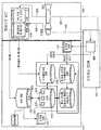
도 1은 본원 발명의 예시적인 실시예에 따른 원격 모니터링 및 진단 시스템의 개략적인 블록도이다.
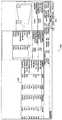
도 2는 분배형(distributed) 제어 시스템(DCS)과 같은, 지역적인(local) 산업 설비 모니터링 및 진단 시스템의 네트워크 아키텍처의 예시적인 실시예의 블록도이다.
도 3은 도 1에 도시된 LMDS와 함께 이용될 수 있는 예시적인 규칙 세트의 블록도이다.
도 4는 본원 발명의 예시적인 실시예에 따른 LMDS의 데이터 흐름 블록도이다.
도 5는 LMDS 또는 원격 모니터링 및 진단 센터로부터 모니터링될 수 있는 구성요소들의 집단의 구성요소들의 조건 및 성능을 모니터링하는 방법의 흐름도이다.
도 6은 설비 사이트 및 원격 모니터링 및 진단 센터에 통신가능하게 결합된 LMDS의 개략적인 블록도이다.
도 7은 네트워크 연결을 통해서 LMDS 또는 원격 모니터링 및 진단 시스템을 통해서 보여질 수 있는 층 1 장면의 화면 캡쳐이다.
도 8은 도 7에 도시된 층 1 장면으로부터 모니터링 탭을 선택한 후에 보여질 수 있는 층 2 장면의 화면 캡쳐이다.
도 9는 도 7에 도시된 층 1 장면 또는 도 8에 도시된 층 2 장면으로부터 성능 탭을 선택한 후에 보여질 수 있는 층 3 장면의 화면 캡쳐이다.
도 10은 본원 발명의 예시적인 실시예에 따른 진동 픽업들(pickups)을 도시하는 층 4 장면의 화면 캡쳐이다.1-10 illustrate exemplary embodiments of the methods and systems disclosed herein.
1 is a schematic block diagram of a remote monitoring and diagnostic system in accordance with an exemplary embodiment of the present invention.
2 is a block diagram of an exemplary embodiment of a network architecture of a local industrial facility monitoring and diagnostic system, such as a distributed control system (DCS).
3 is a block diagram of an exemplary set of rules that may be used with the LMDS shown in FIG.
4 is a data flow block diagram of an LMDS according to an exemplary embodiment of the present invention.
5 is a flow diagram of a method for monitoring conditions and performance of components of a group of components that can be monitored from an LMDS or remote monitoring and diagnostic center.
Figure 6 is a schematic block diagram of an LMDS communicatively coupled to a facility site and a remote monitoring and diagnostic center.
Figure 7 is a screen capture of a
FIG. 8 is a screen capture of a
FIG. 9 is a screen capture of a
10 is a screen capture of a
이하의 구체적인 설명은 예로서 그리고 비제한적인 방식으로 본원 발명의 실시예들을 기술한다. 본원 발명이 산업적, 상업적, 및 주거 적용예들에서 설비 모니터링 및 진단 시스템들을 관리하는 분석적 및 방법적 실시예들에 대한 용도를 일반적으로 가진다.The following detailed description describes embodiments of the invention by way of example and in a non-limiting way. The present invention generally has uses for analytical and methodical embodiments for managing plant monitoring and diagnostic systems in industrial, commercial, and residential applications.
여기에서 사용된 바와 같이, 단수 형태로 인용되고 부정관사("a" 및 "an")의 단어를 앞쪽에 가지는 원소 또는 단계가 복수형 요소들 및 단계들을 명백하게 배제한다고 기재되어 있지 않는 한, 그러한 복수형 요소들 및 단계들이 배제되지 않는다는 것을 이해하여야 할 것이다. 또한, 본원 발명의 "일 실시예"라는 언급은, 인용된 특징들을 또한 포함하는 부가적인 실시예들의 존재를 배제하는 것으로 해석되지 않아야 할 것이다.As used herein, unless the element or step having the word " a " and the word " an "preceding it in singular form is explicitly stated to exclude plural elements and steps, Elements and steps are not excluded. Furthermore, the "one embodiment" of the present invention should not be construed as excluding the existence of additional embodiments which also include the cited features.
본원 개시 내용의 실시예들은, 예를 들어, 그러나 비제한적으로, 사용이 용이한 인터넷, 장비 성능을 개선하면서도 비용들 및 위험들을 감소시키는 진보된 가시화 피쳐들(features)과 결합된 진보된 OEM(original equipment manufacturer) 알고리즘들 및 규칙 세트들이 임베딩된(embedded) 지능형 지역적 모니터링 및 진단 시스템(LMDS)과 같은 네트워크들을 통해서 오일 또는 가스 터보 기계류 장비의 성능 및 건전성과 관련된 정보에 원격적으로 접속하기 위한 협력적인 해결책을 설명한다.Embodiments of the present disclosure may include, but are not limited to, an easy-to-use Internet, an advanced OEM (e.g., integrated with advanced visualization features that reduce equipment costs and risks, original equipment manufacturer algorithms and rules sets to remotely access information related to the performance and health of oil or gas turbomachinery equipment through networks such as intelligent local monitoring and diagnostic systems (LMDS) Describe the solution.
LMDS은 유닛 중지(tripping)를 회피하는데 도움을 주고, 문제들의 발생 전에 문제들을 식별하는 것에 의해서 비정상적인 성능 저하를 결정하고 그리고 맞춤형 시스템들 조율을 통한 최적화를 허용한다. LMDS는 동작 데이터, 경보 및 이벤트 정보를 유닛 제어 패널로부터 수집하고, 지역적인 데이터베이스가 이러한 정보를 중앙 연대기 편작기 내에 그리고 구조화된 쿼리(query) 언어(SQL) 데이터 베이스로 저장하고 그리고 미리 규정된 장비 서비스 지향형 아키텍처(SOA) 데이터 모델이 인터넷 브라우저를 통해서 이를 풍부한(rich) 그래픽적 포맷으로 제시한다.LMDS helps to avoid unit tripping, allows determination of abnormal performance degradation by identifying problems before problems occur, and allows optimization through tuning custom systems. The LMDS collects operational data, alarms, and event information from the unit control panel, and the local database stores this information in the central chronicle editor, as a structured query language (SQL) database, A service-oriented architecture (SOA) data model is presented in a rich, graphical format through an Internet browser.
로그인 시에, 각각의 사이트에 연결된 모든 라인업들 및 트레인들에 대한 건전성 요약을 디스플레이하는 층 1 사이트 레벨 집단 장면이 사용자에게 제시된다. 메인 생산 키 성능 표시자들(KPI들), 예를 들어, 출력 흐름 이용가능성 및 신뢰성 계산들의 작동 상황, 다음의 계획된 중단 뿐만 아니라 신속한 "즉시(right now)" 챠트들이 디스플레이된다. 흉내낸 카툰(cartoon)의 라인업 칼라들은 각각의 유닛에 존재하는 가장 심각한 경보 상황을 도시하고, 적색은 중단 또는 시동 불능을 의미하는 높은 또는 중요한 경보를 나타내고, 오렌지색은 중간 경보를 나타내고, 황색은 낮은 경보를 그리고 녹색은 건전한 동작을 나타낸다. 예시적인 실시예에서, 모니터링 탭은, 가스 터빈 및 압축기에 대한 현재의 KPI들의 리스트를 포함하는 인간 기계 인터페이스(HMI) 층 2 라인업 장면을 제공한다. 여러 실시예들에서, 모니터링 탭은, 비제한적으로, 증기 터빈 및 발전기, 또는 가스 터빈 및 발전기와 같은 다른 장비에 대한 현재의 KPI들의 리스트를 포함하는 HMI 층 2 라인업 장면을 제공한다. 기계의 상황이 컬러 디스플레이뿐만 아니라 리스트화된 KPI들로 도시된다. 사용자가 추가적인 상세 내용을 위해서 찾아 볼 수 있는(drill down) 화면 상의 많은 지역들이 존재한다. 가스 터빈을 클릭하는 것은 해당 가스 터빈의 층 3 기계 장면을 제공한다.At login, a
또한, 각각의 압축기 또는 임의의 다른 피동(driven) 장비에 대한 분리되고, 선택가능한 층 3 장면들이 존재한다. 층 3 장면으로부터, 여러 가지 프로브들(probes) 및 측정에 대한 보다 상세한 내용을 찾기 위한 임의의 수의 하이퍼링크들을 사용자가 이용할 수 있다. 진동 버튼을 클릭하는 것은 층 4 또는 구성요소 장면을 보여준다. 층 4 장면은 진동 센서 픽업들을 보여주고, 그로부터 사용자는, 그들의 진동 프로브들의 지진에 관한(seismic), 축방향 또는 방사상 값들을 포함하는, 보다 더 상세한 내용을 찾아 볼 수 있다. 또한, 성능 KPI들이 성능 탭 상에서 디스플레이된다. 성능 KPI들은 터빈 및 압축기 모두에 대한 열역학적 성능을 포함한다. 압축기의 경우에, 성능 KPI들은 유동 및 속도를 포함한다. 사용자들은, 예를 들어, 원심 압축기의 동작 엔벨로프(envelope) 내의 다종적인(polytropic) 효율을 도시하는, 열역학적 성능 측정들의 라이브(live) 또는 1분마다의 장면을 포함하는 보다 심층적인(in-depth) 분석을 위한 개별적인 KPI을 선택할 수 있다. 라이브 장면에서, 청색 도트들(dots)은 예상되는 레벨을 나타내는 한편, 녹색은 실제 레벨을 보여준다. 분석 탭은, 탐색가능한 KPI 윈도우와 조합될 때, 전문적인 분석 및 고장 수리를 돕기 위한 진보된 차트화 툴을 허용하는 LMDS의 피쳐(feature)이다. 사용자들은 특정 KPI들을 찾을 수 있고, 단일 차트 상에서 또는 나란한 차트들 내에서 복수의 KPI들로부터의 트렌드들을 장면화할 수 있고, 데이터 분석을 위한 시간 기간을 맞춤할 수 있고, 그리고 특정 시간 기간들로 줌(zoom)하기 위해서 슬라이더를 이용할 수 있다. 분석에 만족할 때, 사용자는 설명구 주석들(pretext comments)을 부가할 수 있고, 논의를 위해서 그러한 분석을 고객 또는 동료에게 전송하기 위한 pdf로서 저장할 수 있고, 그리고 미래의 임의의 시간에 즉각적으로 호출하기 위한 즐겨찾기(favorite)로서 분석을 저장함으로써 LMDS을 개인화할 수 있다.There are also separate,
경보 및 이벤트들 윈도우는, 현재의 그리고 과거의 경보들에 관한 정보를 제공하는 다른 툴이다. 여기에서, 사용자는 경보들의 그룹화, 특정 경보들에 대한 탐색 또는 필터링, 경고들의 관찰, 경보 트리거링 태그들(tags)을 신속하게 트렌드화하는 것에 의한 경보 정보 분석, 경고 이력에 대한 주석 부가, 및 경보의 인지 및 소거(clearing)를 포함하는 임의의 수의 과제들을 실시할 수 있다. 진단 엔지니어의 경우에, 경보 윈도우가 트레인에서 실시될 필요가 있는 임의의 진단 작업에 대한 런칭(launch) 지점이 될 수 있다.The Alerts and Events window is another tool that provides information about current and past alerts. Herein, the user can select a group of alerts, search or filter for specific alerts, view alerts, analyze alert information by quickly trending alert triggering tags, annotate on alert history, And may perform any number of tasks, including recognition and clearing of < RTI ID = 0.0 > a < / RTI > In the case of a diagnostic engineer, the alert window can be a launch point for any diagnostic task that needs to be performed on the train.
정보 탭은, 사용자가, 모니터링되는 상이한 구성요소들을 식별하는데 도움을 주기 위해서 날짜가 기재된(dated) 장비 명칭을 획득하도록 허용한다. 정보 탭은 또한 특별한 자산, 예를 들어, 그러나 비제한적으로, 서비스 게시들(bulletins), 구축된 바와 같은(as-built) 도면들, 물자표들(bill of materials; BOM), 및 현장 보고 데이터와 연관된 정보를 포함한다. 온-라인 지원 피쳐는 완전히 탐색가능하고 사용자들에게 시스템의 임의의 양태들을 지시할 수 있다.The information tab allows the user to obtain a dated device name to help the user identify the different components being monitored. Information tabs may also include special assets, such as, but not limited to, service bulletins, as-built drawings, bill of materials (BOM), and field reporting data Lt; / RTI > The on-line support feature is fully searchable and can direct users to any aspects of the system.
도 1은 본원 발명의 예시적인 실시예에 따른 원격 모니터링 및 진단 시스템(100)의 개략적인 블록도이다. 예시적인 실시예에서, 시스템(100)이 원격 모니터링 및 진단 센터(102)를 포함한다. 원격 모니터링 및 진단 센터(102)는, 관리 엔티티(entity)와 같은 분리된 사업 엔티티에 의해서 구입되고 운영되는 복수의 장비의 OEM과 같은 엔티티에 의해서 운영된다. 예시적인 실시예에서, OEM 및 운영 엔티티가 지원 배열체(arrangement) 내로 진입하고, 그에 의해서 OEM은 구매한 장비와 관련된 서비스들을 운영 엔티티로 제공한다. 운영 엔티티는 단일 사이트 또는 복수 사이트들에서 구매한 장비를 소유 및 운영할 수 있을 것이다. 또한, OEM이 복수의 운영 엔티티들로 지원 배열체들로 진입할 수 있을 것이고, 운영 엔티티 각각이 그들 자신의 단일 사이트 또는 복수 사이트들을 운영한다. 복수의 사이트들의 각각이 동일한 개별적인 장비 또는 복수의 동일한 장비의 세트들, 예를 들어 장비의 트레인들(trains)을 포함할 수 있을 것이다. 부가적으로, 장비의 적어도 일부가 하나의 사이트에 대해서 특유할 수 있거나 모든 사이트들에 대해서 특유할 수 있을 것이다.1 is a schematic block diagram of a remote monitoring and
예시적인 실시예에서, 제 1 사이트(104)가 하나 이상의 프로세스 분석기들(106), 장비 모니터링 시스템들(108), 장비 지역적 제어 센터들(110), 및/또는 모니터링 및 경보 패널들(112)을 포함하고, 상기 모니터링 및 경보 패널들(112)의 각각은 개별적인 장비의 제어 및 동작을 실시하기 위해서 개별적인 장비 센서들 및 제어 장비와 인터페이스하도록 구성된다. 하나 이상의 프로세스 분석기들(106), 장비 모니터링 시스템들(108), 장비 지역적 제어 센터들(110), 및/또는 모니터링 및 경보 패널들(112)이 네트워크(116)를 통해서 지능형 모니터링 및 진단 시스템(114)으로 통신가능하게 결합된다. 지능형 모니터링 및 진단(IMAD) 시스템(114)은, 비제한적으로, 원격 모니터링 및 진단 센터(102)와 같은 오프 사이트 시스템들 및 다른 온-사이트 시스템들(도 1에 도시하지 않음)과 통신하도록 추가로 구성된다. 여러 실시예들에서, IMDA(114)가, 예를 들어, 전용 네트워크(118), 무선 링크(120), 및 인터넷(122)을 이용하여, 원격 모니터링 및 진단 센터(102)와 통신하도록 구성된다.In an exemplary embodiment, the
복수의 다른 사이트들의 각각, 예를 들어, 제 2 사이트(124) 및 n번째 사이트(126)가 제 1 사이트(104)와 실질적으로 유사할 수 있으나, 제 1 사이트(104)와 정확하게 유사하거나 그렇지 않을 수 있을 것이다.Each of the plurality of other sites, e.g., the
도 2는 분배형 제어 시스템(DCS)(201)과 같은 지역적인 산업 설비 모니터링 및 진단 시스템의 네트워크 아키텍처(200)의 예시적인 실시예의 블록도이다. 산업 설비가 복수의 설비 장비, 예를 들어, 상호 연결 파이핑을 통해서 유동 소통식으로 결합되고 하나 이상의 원격 입/출력(I/O) 모듈들 및 상호연결 케이블링 및/또는 무선 통신을 통해서 DCS(201)와 신호 소통식으로 결합된, 가스 터빈들, 원심 압축기들, 기어 박스들, 발전기들, 펌프들, 모터들, 팬들, 및 프로세스 모니터링 센서들을 포함할 수 있을 것이다. 예시적인 실시예에서, 산업 설비가 네트워크 백본(203)을 포함하는 DCS(201)를 포함한다. 네트워크 백본(203)이, 예를 들어, 꼬여진 쌍의 케이블, 외피를 가지는 동축 케이블 또는 광섬유 케이블로 제조된 하드와이어드(hardwired) 데이터 통신 경로일 수 있고, 또는 적어도 부분적으로 무선형일 수 있을 것이다. DCS(201)이 또한, 네트워크 백본(203)을 통해서, 산업 설비 사이트에 또는 원격 위치들에 배치된, 설비 장비에 통신가능하게 결합된 프로세서(205)를 포함할 수 있을 것이다. 임의의 수의 기계들이 네트워크 백본(203)에 무선으로 결합될 수 있다는 것을 이해할 수 있을 것이다. 기계들의 일부가 네트워크 백본(203)에 하드와이어링될 수 있을 것이고, 기계들의 다른 부분들이, DCS(201)에 통신가능하게 결합된 무선 기지국(207)을 통해서 백본(203)에 무선으로 결합될 수 있을 것이다. 무선 기지국(207)이, 산업 설비로부터 원격에 위치되나 산업 설비 내의 하나 이상의 시스템과 여전히 상호 연결된 장비 또는 센서들에서와 같이, DCS(201)의 유효 통신 범위를 확장하기 위해서 이용될 수 있을 것이다.2 is a block diagram of an exemplary embodiment of a
DCS(201)이 복수의 장비와 연관된 동작 매개변수들을 수신 및 디스플레이하도록, 그리고 자동 제어 신호들을 생성하고 산업 설비의 장비의 동작을 제어하기 위한 수동 제어 입력들을 수신하도록 구성될 수 있을 것이다. 예시적인 실시예에서, DCS(201)이, 산업 설비 기계들의 온라인 모니터링 및 진단을 허용하는 DCS(201)에서 수신된 데이터를 분석하기 위해서 프로세서(205)를 제어하도록 구성된 소프트웨어 코드 세그먼트를 포함할 수 있을 것이다. 데이터가, 가스 터빈들, 원심 압축기들, 펌프들 및 모터들, 연관된 프로세스 센서들, 그리고, 예를 들어, 진동, 지진, 온도, 압력, 전류, 전압, 주변 온도 및 주변 습도 센서들을 포함하는 지역적인 환경 센서들을 포함하는 각각의 기계로부터 수집될 수 있을 것이다. 데이터가 지역적인 진단 모듈 또는 원격 입/출력 모듈에 의해서 미리-프로세싱될 수 있을 것이고, 또는 미가공(raw) 형태로 DCS(201)으로 전송될 수 있을 것이다.The
지역적인 모니터링 및 진단 시스템(LMDS)(213)이, 네트워크 백본(203)을 통해서 DCS(201) 및 다른 제어 시스템들(209) 및 데이터 공급원들과 통신하는, 예를 들어, 개인용 컴퓨터(PC)와 같은 분리된 부가형(add-on) 하드웨어 장치일 수 있을 것이다. LMDS(213)이 또한 DCS(201) 상에서 및/또는 다른 제어 시스템들(209) 중 하나 이상에서 실행되는 소프트웨어 프로그램 세그먼트 내에서 구현될 수 있을 것이다. 따라서, LMDS(213)이 분배된 방식으로 동작할 수 있을 것이고, 그에 따라 소프트웨어 프로그램 세그먼트의 일부가 몇 개의 프로세서들 상에서 동시에 실행될 수 있을 것이다. 따라서, LMDS(213)이 DCS(201) 및 다른 제어 시스템들(209) 내로 완전히 통합될 수 있을 것이다. 산업 설비의 전반적인 고찰을 이용하여 기계들 및 기계들을 채용한 프로세스의 동작적 건전성을 결정하기 위해서, LMDS(213)은 DCS(201), 데이터 공급원들, 및 다른 제어 시스템들(209)에 의해서 수신된 데이터를 분석한다.A local monitoring and diagnostic system (LMDS) 213 is connected to the
예시적인 실시예에서, 네트워크 아키텍처(100)가 서버 등급 컴퓨터(202) 및 하나 이상의 클라이언트 시스템들(203)을 포함한다. 서버 등급 컴퓨터(202)는 데이터베이스 서버(206), 애플리케이션 서버(208), 웹 서버(210), 팩스 서버(212), 디렉토리 서버(214) 및 메일 서버(216)를 더 포함한다. 서버들(206, 208, 210, 212, 214 및 216) 각각은 서버 등급 컴퓨터(202)에서 실행되는 소프트웨어로 구현될 수 있을 것이고, 또는 서버들(206, 208, 210, 212, 214 및 216)의 임의의 조합들이 단독으로 또는 근거리 네트워크(LAN)(미도시)에 결합된 분리된 서버 등급 컴퓨터들 상에서 조합되어 구현될 수 있을 것이다. 데이터 저장 유닛(220)이 서버 등급 컴퓨터(202)에 결합된다. 또한, 시스템 관리자 워크 스테이션, 사용자 워크 스테이션, 및/또는 감독자의 워크 스테이션과 같은 워크 스테이션(222)이 네트워크 백본(203)에 결합된다. 대안적으로, 워크 스테이션(222)이 인터넷 링크(226)를 이용하여 네트워크 백본(203)에 결합되거나, 무선 연결을 통해서, 예를 들어 무선 기지국(207)을 통해서 연결된다.In an exemplary embodiment,
각각의 워크 스테이션(222)이 웹 브라우저를 가지는 개인용 컴퓨터일 수 있을 것이다. 비록 전형적으로 워크스테이션에서 실시되는 기능들이 각각의 워크스테이션들(222)에서 실시되는 것을 설명되어 있지만, 그러한 기능들이 네트워크 백본(203)에 결합된 많은 개인용 컴퓨터들 중 하나에서 실시될 수 있을 것이다. 네트워크 백본(203)에 접속하는 개인들에 의해서 실시될 수 있는 상이한 타입들의 기능들의 이해를 돕기 위해서, 단지 분리된 예시적 기능들과 연관된 것으로 워크스테이션들(222)을 설명하였다.Each
서버 등급 컴퓨터(202)는, 피고용자(228) 및 제 3 자들, 예를 들어, 서비스 제공자들(230)을 포함하는, 다양한 개인들에 대해서 통신가능하게 결합되도록 구성된다. 예시적인 실시예에서의 통신이 인터넷을 이용하여 실시되는 것으로 설명되어 있으나, 임의의 다른 광역 네트워크(WAN) 타입 통신이 다른 실시예에서 이용될 수 있고, 다시 말해서 시스템들 및 프로세스들은 인터넷을 이용하여 실시되는 것으로 제한되지 않는다.The
예시적인 실시예에서, 워크스테이션(232)을 가지는 임의의 승인된 개인이 LMDS(213)에 접속할 수 있다. 클라이언트 시스템들 중 적어도 하나가 원격 위치에 위치된 매니저 워크스테이션(234)을 포함할 수 있을 것이다. 워크스테이션들(222)이 웹 브라우저를 가지는 개인용 컴퓨터들 사에서 구현될 수 있을 것이다. 또한, 워크스테이션들(22)이 서버 등급 컴퓨터(202)와 통신하도록 구성된다. 또한, 팩스 서버(212)가, 전화 링크(미도시)를 이용하여 클라이언트 시스템(236)을 포함하는 원격적으로 위치된 클라이언트 시스템들과 통신한다. 팩스 서버(212)가 또한 다른 클라이언트 시스템들(228, 230, 및 234)과 통신하도록 구성된다.In an exemplary embodiment, any authorized individual with a
이하에서 보다 구체적으로 설명하는 바와 같은, LMDS(213)의 컴퓨터화된 모델링 및 분석 툴들이 서버(202) 내에 저장될 수 있고 클라이언트 시스템들(204) 중 임의의 하나에서의 요청자에 의해서 접속될 수 있다. 일 실시예에서, 클라이언트 시스템(204)이 웹 브라우저를 포함하는 컴퓨터들이고, 그에 따라 서버 등급 컴퓨터(202)가 인터넷을 이용하여 클라이언트 시스템들(204)에 접속할 수 있다. 클라이언트 시스템들(204)이, 근거리 네트워크(LAN) 또는 광역 네트워크(WAN), 다이얼-인-연결들(dial-in-connections), 케이블 모뎀들, 및 특별한 고속 ISDN 라인들과 같은, 네트워크를 포함하는 많은 인터페이스들을 통해서 인터넷에 대해서 상호 연결된다. 클라이언트 시스템들(204)이 웹-기반의 전화, 개인 정보 단말기(PDA), 또는 다른 웹-기반의 연결가능한 장비를 포함하는, 인터넷에 연결될 수 있는 임의의 장치일 수 있다. 데이터베이스 서버(206)가, 이하에서 보다 구체적으로 설명되는 바와 같은, 산업 설비(10)에 관한 정보를 포함하는 데이터베이스(240)에 연결된다. 일 실시예에서, 중앙집중형 데이터베이스(240)가 서버 등급 컴퓨터(202)에 저장되고, 클라이언트 시스템들(204) 중 하나를 통해서 서버 등급 컴퓨터(202)로 로그하는 것에 의해서, 클라이언트 시스템들(204) 하나에서 잠재적인 사용자들에 의해서 접속될 수 있다. 대안적인 실시예에서, 데이터베이스(240)가 서버 등급 컴퓨터(202)로부터 원격지에 저장되고 비-중앙집중형일 수 있을 것이다.The computerized modeling and analysis tools of the
다른 산업 설비 시스템들이, 네트워크 백본(203)에 대한 독립적인 연결부들을 통해서 서버 등급 컴퓨터(202) 및/또는 클라이언트 시스템들(204)로 접속될 수 있는 데이터를 제공할 수 있을 것이다. 상호작용적인 전자 기술 매뉴얼 서버(242)는 각각의 기계의 구성과 관련된 기계 데이터에 대한 요청들에 대해서 서비스한다. 그러한 데이터가, 펌프 곡선들, 모터 마력 레이팅(rating), 절연 등급, 및 프레임 크기, 설계 매개변수들, 예를 들어 치수들, 회전자 바아들 또는 임펠러 블레이드들의 수, 및 기계류 유지보수 이력, 예를 들어 기계에 대한 현장 변경들(field alterations), 교정전(as-found) 및 교정후(as-left) 정렬 측정치들, 및 최초의 설계 조건으로 기계를 복귀시키지 않는 기계에서 실시되는 수리들과 같은, 동작적인 능력들을 포함할 수 있을 것이다.Other industrial plant systems may provide data that can be connected to the
휴대용 진동 모니터(244)가, 직접적으로 또는 워크스테이션들(222) 또는 클라이언트 시스템들(204) 내에 포함된 포트들과 같은 컴퓨터 입력 포트를 통해서 간헐적으로, LAN에 결합될 수 있을 것이다. 전형적으로, 진동 데이터가 루트 내에서 수집되고, 주기적으로, 예를 들어 월 단위로 또는 다른 주기로 기계들의 미리 결정된 리스트로부터 데이터를 수집한다. 또한, 진동 데이터가 고장 수리(troubleshooting), 유지보수, 및 주문 활동들과 함께 수집될 수 있을 것이다. 또한, 진동 데이터가 실시간 기반으로 또는 거의 실시간 기반으로 연속적으로 수집될 수 있을 것이다. 그러한 데이터가 LMDS(213)의 알고리즘들을 위한 새로운 기준선을 제공할 수 있을 것이다. 유사하게, 프로세스 데이터가 루트 기반으로 또는 고장 수리, 유지보수, 및 주문 활동들 중에 수집될 수 있을 것이다. 또한, 일부 프로세스 데이터가 실시간 기반으로 또는 거의 실시간 기반으로 연속적으로 수집될 수 있을 것이다. 특정 프로세스 매개변수들이 영구적으로 지시되지 않을 수 있을 것이고, LMDS(213)으로 접속될 수 있도록 워크스테이션(222)을 통해서 DCS(201)으로 다운로드될 수 있는 프로세스 매개변수 데이터를 수집하기 위해서 휴대용 프로세스 데이터 수집기(245)가 이용될 수 있을 것이다. 예를 들어 프로세스 유체 조성 분석기들 및 오염물 방출 분석기들과 같은, 다른 프로세스 매개변수 데이터가 복수의 온-라인 모니터들(246)을 통해서 DCS(201)으로 제공될 수 있을 것이다.The
여러 가지 기계들로 공급되는 또는 산업 설비를 가지는 발전기들에 의해서 발전되는 전력이 각각의 기계와 연관된 모터 보호 릴레이(248)에 의해서 모니터링될 수 있을 것이다. 전형적으로, 그러한 릴레이들(248)이 모터 제어 센터(MCC) 내의 또는 기계로 공급하는 스위치기어(250) 내의 모니터링되는 장비로부터 원격에 위치된다. 또한, 릴레이들(248)을 보호하기 위해서, 예를 들어 스위치야드(switchyard) 내의 산업 설비에 위치되는 전력 공급 또는 전력 전달 시스템(미도시) 장비 또는 원격 전송 라인 브레이커들 및 라인 매개변수들을 LMDS(213)으로 제공하는 감독자 제어 및 데이터 획득 시스템(SCADA)을 스위치기어(250)가 또한 포함할 수 있을 것이다.Power generated by generators that are supplied to various machines or that have industrial facilities may be monitored by a
도 3은 LMDS(213)(도 1에 도시됨)과 함께 이용될 수 있는 예시적인 규칙 세트(280)의 블록도이다. 규칙 세트(280)가 하나 이상의 고객 규칙들의 조합, 및 고객 규칙들의 상태 및 거동을 규정하는 일련의 특성들일 수 있을 것이다. 상기 규칙들 및 특성들이 번들화되고(bundled) XML 스트링의 포맷으로 저장될 수 있을 것이고, 상기 규칙들 및 특성들은, 파일로 저장될 때, 25개의 문자 영숫자 키를 기초로 암호화될 수 있을 것이다. 규칙 세트(280)가, 하나 이상의 입력들(282) 및 하나 이상의 출력들(284)을 포함하는 모듈형 지식 셀(knowledge cell)이다. 입력들(282)이, LMDS(213) 내의 특정 위치들로부터 규칙 세트(280)로 데이터를 지시하는 소프트웨어 포트들일 수 있을 것이다. 예를 들어, 펌프 아웃보드 진동 센서로부터의 입력이 DCS(201) 내의 하드웨어 입력 단자로 전송될 수 있을 것이다. DCS(201)은, 신호를 수신하기 위해서 해당 단자에서 신호를 샘플링할 수 있을 것이다. 이어서, 상기 신호가 프로세싱되고 DCS(201)으로 접속가능한 및/또는 DCS(201)에 일체화된 메모리 내의 위치에 저장될 수 있을 것이다. 규칙 세트(280)의 제 1 입력(286)이 메몰 내의 위치로 맵핑될 수 있을 것이고, 그에 따라 메모리 내의 위치의 콘텐츠가 입력으로서 규칙 세트(280)에 대해서 이용될 수 있을 것이다. 유사하게, 출력(288)이 DCS(201)으로 접속가능한 메모리 또는 다른 메모리 내의 다른 위치로 맵핑될 수 있을 것이고, 그에 따라 메모리 내의 위치가 규칙 세트(280)의 출력(288)을 포함할 수 있을 것이다.FIG. 3 is a block diagram of an exemplary rule set 280 that may be used with the LMDS 213 (shown in FIG. 1). The rule set 280 may be a set of one or more customer rules, and a set of characteristics that define the state and behavior of the customer rules. The rules and properties may be bundled and stored in the format of an XML string, and the rules and properties, when stored in a file, may be encrypted based on a 25 alphanumeric key. The rule set 280 is a modular knowledge cell that includes one or
예시적인 실시예에서, 규칙 세트(280)가, 예를 들어, 가스 재주입 설비, 액체 천연 가스(LNG) 설비, 발전소, 정유, 화학 처리 시설과 같은, 산업 설비 내의 장비 동작과 연관된 특정 문제들의 모니터링 및 진단과 관련된 하나 이상의 규칙들을 포함한다. 비록 규칙 세트(280)가 산업 설비와 함께 이용되는 것으로서 설명되어 있지만, 규칙 세트(280)가 임의의 지식을 캡쳐하도록 그리고 임의의 분야에서 해결책들을 결정하기 위해서 사용되도록 적절하게 구성될 수 있을 것이다. 예를 들어, 규칙 세트(280)가 경제적인 거동, 재정적인 활동, 기후 현상, 및 설계 프로세스들과 관련한 지식을 포함할 수 있을 것이다. 이어서, 규칙 세트(280)를 이용하여 이러한 분야들에서의 문제점들에 대한 해결책들을 결정할 수 있을 것이다. 규칙 세트(280)가 하나 또는 많은 공급원들로부터의 지식을 포함하고, 그에 따라 그러한 지식이, 규칙 세트(280)가 적용되는 임의의 시스템으로 전달된다. 상기 지식은, 출력들(284)을 입력들(282)에 대해서 관련시키는 규칙들의 형태로 캡쳐되고, 그에 따라 입력들(282) 및 출력들(284)의 재원(specification)은 규칙 세트(280)가 LMDS(213)으로 적용될 수 있게 한다. 규칙 세트(280)가 특정 공장 설비 자산(asset)에 대해서 특정된 유일한 규칙들을 포함할 수 있을 것이고, 해당 특정 공장 설비 자산과 연관된 하나의 가능한 문제만으로 지시될 수 있을 것이다. 예를 들어, 규칙 세트(280)가, 모터 또는 모터/펌프 조합으로 적용될 수 있는 유일한 규칙들을 포함할 수 있을 것이다. 규칙 세트(280)가, 진동 데이터를 이용하여 모터/펌프 조합의 건전성을 결정하는 규칙들만을 포함할 수 있을 것이다. 규칙 세트(280)가 또한, 진동 분석 기술들에 더하여, 그러나, 예를 들어, 모터/펌프 조합에 대한 성능 계산 툴들 및/또는 재정 계산 툴들을 포함하는 한 벌의 진단 툴들을 이용하여 모터/펌프 조합의 건전성을 결정하는 규칙들을 포함할 수 있을 것이다.In an exemplary embodiment, the set of
동작 중에, 입력들(282)과 출력들(284) 사이의 관계를 사용자에게 알려주는 소프트웨어 개발 툴에서 규칙 세트(280)가 생성된다. 입력들(282)이, 예를 들어, 디지털 신호들, 아날로그 신호들, 파형들, 프로세싱된 신호들, 수작업으로 입력된 매개변수들 및/또는 구성 매개변수들, 그리고 다른 규칙 세트들로부터의 출력들을 나타내는 데이터를 수신할 수 있을 것이다. 규칙 세트(280) 내의 규칙들이 논리적 규칙들, 수치적 알고리즘들, 파형 및 신호 프로세싱 기술들의 적용, 전문(expert) 시스템 및 인공지능 알고리즘들, 통계적 툴들, 및 출력들(284)을 입력들(282)에 대해서 관련시킬 수 있는 임의의 다른 표현을 포함할 수 있을 것이다. 각각의 출력(284)을 수신하도록 보유되고(reserved) 구성되는 메모리 내의 개별적인 위치들로 출력들(284)이 맵핑될 수 있을 것이다. 이어서, LMDS(213) 및 DCS(201)이 임의의 모니터링 및/또는 제어 기능들을 달성하기 위해서 메모리 내의 위치들을 이용할 수 있을 것이고, LMDS(213) 및 DCS(201)이 실시를 위해서 프로그래밍될 수 있을 것이다. 비록, 직접적으로 또는 개재 장치들을 통해서 간접적으로, 입력들(282)이 규칙 세트(280)로 공급될 수 있고 출력들(284)이 규칙 세트(280)로 공급될 수 있지만, 규칙 세트(280)의 규칙들이 LMDS(213) 및 DCS(201)과 독립적으로 동작한다.In operation, a set of
규칙 세트(280)의 생성 중에, 해당 분야의 인간 전문가가 하나 이상의 규칙들을 프로그래밍하는 것에 의해서 개발 툴을 이용하여 특정 자산에 대해서 특별한 해당 분야에 관한 지식을 전달한다. 그러한 규칙들은, 규칙들의 코팅이 필요하지 않도록, 출력들(284)과 입력들(282) 사이의 관계식들을 생성하는 것에 의해서 생성된다. 그래픽적인 방법들을 이용하여, 예를 들어, 개발 툴로 구축된 그래픽적인 사용자 인터페이스 상에서의 드래그 및 드롭을 이용하여, 피연산자들(operands)이 피연산자들의 라이브러리로부터 선택될 수 있을 것이다. 피연산자의 그래픽적인 표현이 화면 디스플레이(미도시)의 라이브러리 부분으로부터 선택될 수 있을 것이고 그리고 규칙 생성 부분 내로 드래그되고 드롭될 수 있을 것이다. 입력(282)과 피연산자들 사이의 관계들이 논리적인 디스플레이 방식으로 배열되고, 선택된 입력들(282) 중의 특정 입력들 및 특정 피연산자들을 기초로 적절한 경우에, 제약들과 같은 값들을 사용자에게 알린다. 전문가의 지식을 캡쳐하기 위해서 필요한 바와 같은 많은 규칙들이 생성된다. 따라서, 규칙 세트(280)가, 고객의 요건들 및 규칙 세트(280)의 특별한 분야에서의 기술 수준을 기초로, 보다 견실한 진단 세트 및/또는 모니터링 규칙들 또는 비교적 덜 견실한 진단 및/또는 모니터링 규칙들의 세트를 포함할 수 있을 것이다. 입력들(282)의 여러 가지 조합들 및 값들이 출력들(284)에서 예상되는 출력들을 생성하도록 보장하기 위해서, 개발 툴은 개발 중에 테스팅 규칙 세트(280)를 위한 자원들을 제공한다. 규칙 세트(280) 내의 캡쳐된 지식 또는 지적 재산을 보호하기 위해서, 개발 암호화 코드를 이용하여, 암호화 키를 가진 사람을 제외하고, 규칙 세트(280)를 변경하지 못하도록 록킹할 수 있을 것이다. 예를 들어, 규칙 세트(280)의 생성자가 규칙 세트(280)의 최종 사용자들을 제한하기 위해서 암호화 키를 유지할 수 있을 것이고, 생성자는 최종 사용자 또는 제 3 자들에게 암호화 키를 판매하거나 또는 최종 사용자 또는 제 3 자들에게 대해서 소정 기간 동안 라이센스화할 수 있을 것이고, 상기 제 3 자들은 최종 사용자에게 서비스들을 제공할 수 있을 것이다.During the creation of the rule set 280, a human expert in the field communicates knowledge about a particular area of interest to a particular asset using a development tool by programming one or more rules. Such rules are created by creating relationships between
개발 후에, 규칙 세트(280)가 분배 모드로 진입할 수 있을 것이고, 상기 분배 모드에서 규칙 세트(280)가 전송가능한 형태, 예를 들어, 이메일, CD-ROM, 인터넷 사이트에 대한 링크, 또는 컴퓨터 판독가능 파일의 전송을 위한 임의의 다른 수단을 통해서 고객에게 전송될 수 있는 XML 파일로 변환된다. 규칙 세트(280)는, 예를 들어, 분배 암호화 키를 구매하는 것에 의해서, 최종 사용자가 생성자에 의해서 승인되지 않은 경우에, 규칙 세트(280)의 이용을 방지할 수 있는 분배 암호화 코드로 암호화될 수 있을 것이다. 컴퓨터 판독가능 파일을 전송할 수 있는 임의의 수단을 통해서, 규칙 세트(280)가 최종 사용자에 의해서 수신될 수 있을 것이다. LMDS(213)의 일부를 형성하는 소프트웨어 플랫폼일 수 있는 규칙 세트 관리자가 규칙 세트(280)의 분배가능한 형태를 수신할 수 있을 것이고, 그 형태를 LMDS(213)이 이용가능한 포맷으로 변환할 수 있을 것이다. 그래픽적인 사용자 인터페이스는, 최종 사용자로 하여금 대상들(objects)로서 하나 이상의 규칙 세트들(280)을 조작할 수 있게 한다. 입력들(282) 및 메모리 내의 상응하는 위치들이 정확하게 맵핑되도록 그리고 출력들(284) 및 그 출력들의 메모리 내의 상응하는 위치들이 정확하게 맵핑되도록, 규칙 세트(280)가 적용될 수 있을 것이다. 초기에 적용될 때, 규칙 세트(280)가 시운전(trial) 모드로 위치될 수 있을 것이고, 그러한 시운전 모드에서, 규칙 세트(280)에 의해서 검출될 수 있는 비정상적인 거동의 통지들이 분배되지 않거나 제한된 기반 상에서 분배되는 것을 제외하고, 규칙 세트(280)는 생성된 바에 따라서 동작한다. 시운전 모드 중에, 규칙 세트(280)가 동작 분위기 내에서 정확하게 동작하도록 보장하기 위해서, 품질 보증들(certifications)이 실시될 수 있을 것이다. 품질 보증이 완료될 때, 규칙 세트(280)가 위임(commission)으로 배치될 수 있고, 그러한 위임에서 규칙 세트(280)가 규칙 세트(280) 내의 규칙들의 완전한 기능으로 LMDS(213) 상에서 동작한다. 다른 실시예에서, 규칙 세트(280)가 단지 2개 모드들 즉, 시운전 모드 및 라이브 모드를 가지는 수명(life) 사이클을 포함한다. 시운전 모드에서, 이벤트들이 생성되지 않거나 송신된 통지들이 없는 경우를 제외하고, 규칙들이 정상적으로 작동하고, 라이브 모드는 위임에 배치되는 것과 실질적으로 유사하다.After development, the rule set 280 will be able to enter the distribution mode, and in the distribution mode, the rule set 280 will be in a form that can be transmitted, e.g., email, CD-ROM, To an XML file that can be transmitted to the customer via any other means for transferring the readable file. The rule set 280 may be encrypted with a distributed encryption code that can prevent use of the rule set 280, for example, by purchasing a distributed encryption key if the end user is not authorized by the producer It will be possible. Through any means capable of transferring computer readable files, rule set 280 may be received by the end user. A rule set manager, which may be a software platform that forms part of the
예시적인 실시예에서, 규칙 세트들이 이하 중 하나 이상을 포함할 수 있을 것이다:In an exemplary embodiment, the rule sets may include one or more of the following:
가스 터빈 이용가능성 규칙 세트들:Gas turbine availability rule sets:
1. 휠 공간 온도1. Wheel space temperature
2. 배기 온도 체크2. Exhaust temperature check
3. 배기 온도 스프레드(Spread)3. Spread of exhaust temperature
4. 결함 콤 로케이터(Faulty Comb Locator)4. Faulty Comb Locator
5. DLN 전달5. DLN forwarding
6. 프레임 검출기 모니터링6. Frame detector monitoring
7. 윤활유 오일 온도7. Lubricating oil temperature
8. 유입 필터8. Inflow filter
9. 압축기 압력 비율9. Compressor pressure ratio
10. 전송기 문제들을 검출하기 위한 IBV/IGV/IBH/GCV/FPG 규칙10. IBV / IGV / IBH / GCV / FPG Rules for Detecting Transmitter Problems
가스 터빈 성능 규칙 세트들:Gas Turbine Performance Rule Sets:
1. 축방향 콤프(Comp) 효율1. Ax Comp Comp efficiency
2. 축방향 콤프 유동2. Axial Comf Flow
3. 출력 파워 저하3. Output power degradation
4. 열 레이트(Rate) 저하4. Rate decrease
5. 부분 부하 연료 소비5. Partial load fuel consumption
원심 압축기 이용가능성 규칙 세트들:Centrifugal compressor availability rules sets:
일차 밀봉 가스 시스템 이용가능성 규칙 세트들:Primary seal gas system availability rules sets:
1. 가스 필터들 내의 분진1. Dust in gas filters
2. PDV 오작동(DE)2. PDV malfunction (DE)
3. PDV 오작동(NDE)3. PDV malfunction (NDE)
4. 이차 밀봉 PDV 오작동4. Second seal PDV malfunction
5. 삼차 밀봉 PV 오작동5. Triple seal PV malfunction
6. 앰플리플로우(Ampliflow) 가스켓 불량6. Ampliflow gasket defective
7. 패널 주위의 지역적인 누설7. Local leakage around the panel
8. 히터 고장8. Heater failure
건식 가스 밀봉 카트리지들 이용가능성 규칙 세트들:Dry gas seal cartridges Availability rule sets:
9. 유수분리기(coalescer) 불량9. Defective coalescer
10. 일차 밀봉 카트리지 손상 DE10. Primary seal cartridge damage DE
11. 일차 밀봉 카트리지 손상 NDE11. Primary seal cartridge damage NDE
12. 이차 밀봉 카트리지 손상 DE12. Secondary seal cartridge damage DE
13. 이차 밀봉 카트리지 손상 NDE13. Secondary seal cartridge damage NDE
14. 탄화수소 응축14. Hydrocarbon condensation
15. 이차 벤트(지역적)를 통한 밀봉 가스 탈출15. Escape the sealing gas through the secondary vent (local)
16. 일차 밀봉 타격 개방 DE16. Primary seal striking opening DE
17. 일차 밀봉 타격 개방 NDE17. Primary seal striking open NDE
18. 단부 밀봉 증가된 간극 DE18. End Sealed Increased Clearance DE
19. 단부 밀봉 증가된 간극 NDE19. End Seal Increased Clearance NDE
20. 이차 밀봉 타격 개방 DE20. Secondary seal blow opening DE
21. 이차 밀봉 타격 개방 NDE21. Secondary seal blow opening NDE
일차 벤트 시스템Primary Vent Systems
22. 낮은 플레어(Flare) 압력22. Low Flare Pressure
23. 높은 플레어 압력23. High flare pressure
분리 가스 시스템 이용가능성Separation gas system availability
24. 삼차 밀봉 불량(오일 이동)24. Tertiary sealing failure (oil movement)
질소 공급 시스템Nitrogen supply system
25. 질소 공급 시스템 불량25. Poor nitrogen supply system
원심 압축기 성능 규칙 세트들:Centrifugal compressor performance rule sets:
1. 실제 성능1. Actual performance
2. 예상된 성능2. Expected Performance
3. 효율 강하 경보3. Efficiency drop alarm
4. 헤드 계수델타(Head CoeffDelta)4. Head coefficient delta (Head Coeff Delta)
5. 유동 계수델타5. Flow coefficient delta
6. 흡입 조건6. Suction condition
일 실시예에서, 가스 터빈 엔진의 동작 조건들에 대한 예상되는 휠공간(wheelspace) 온도를 계산하도록 휠공간 온도 규칙 세트가 구성된다. 휠공간 온도 규칙 세트의 장점은, 예상되는 휠공간 온도의 상부 및 하부 경계들을 예측하기 위해서 상이한 GT 구성요소들과 압축기 성능을 링크시키는 예측가능하고 적응가능한(adaptable) 문턱값이다.In one embodiment, a set of wheel space temperature rules is configured to calculate an expected wheel space temperature for operating conditions of the gas turbine engine. The advantage of the wheel space temperature rule set is a predictable and adaptable threshold that links compressor performance with different GT components to predict the upper and lower boundaries of the expected wheel space temperature.
연소기 소용돌이 각도 규칙 세트는, 가능성 있는 오류 연소기의 위치를 식별하기 위해서, 변화되는 부하들에서 측정된 대표적인 배기 가스 온도와 연소기 공급원-위치 사이의 각도를 평가하도록 구성된다.The combustor swirl angle rule set is configured to evaluate an angle between a representative exhaust gas temperature measured at the varying loads and the combustor source-position in order to identify the location of a potential erroneous combustor.
배기 온도 스프레드 규칙 세트는, 각각의 연소 모드에서 그리고 변화되는 부하들에서 배기 온도 프로파일 내의 고온/저온 스폿(spot)을 정확하게 식별하도록, 그리고 스프레드 부조화(anomaly)를 정밀하게 식별하고 그 부조화를 연소 모드 및 부하에 링크시키기 위해서 미리 결정된 문턱값을 통해서 배기 온도 부조화를 규정하도록 구성된다.The exhaust temperature spread rule set can be used to accurately identify high temperature / low temperature spots in the exhaust temperature profile in each combustion mode and at varying loads, and to precisely identify spread anomalies, And to define exhaust temperature discrepancy through a predetermined threshold to link to the load.
이차 프레임 검출기 모니터링 규칙 세트는, 잘못된 센서들로 인한 중지를 피하기 위해서 아날로그 및 디지털 신호들을 모니터링하는 것을 기초로 오류 프레임 검출기를 예측하도록 구성된다.The secondary frame detector monitoring rule set is configured to predict an error frame detector based on monitoring analog and digital signals to avoid pauses due to erroneous sensors.
축류 압축기 효율 규칙 세트는, 정상 상태 조건들에서, 축류 압축기 효율을 온라인으로 계산하도록, 그리고 시간에 따른 저하를 모니터링하도록 구성된다.The set of axial compressor efficiency rules is configured to calculate the axial compressor efficiency on-line in steady state conditions, and to monitor the decline over time.
축류 압축기 효율 규칙 세트는 ISO 조건들 및 100% 속도로 교정된 축류 압축기 유동 효율을 온라인으로 계산하도록, 그리고 시간에 따른 저하를 모니터링하도록 구성된다.The Axial Compressor Efficiency Rule Set is configured to calculate the ISO conditions and the axial flow compressor flow efficiency calibrated at 100% speed on-line, and to monitor the degradation over time.
가스 터빈 출력 파워 저하 규칙 세트는, 출력 파워 감소를 피하기 위해서, ISO 조건들 및 100% 속도로 교정되고, 가스 터빈 엔진 성능 맵들을 이용하여 초기 기준 값에 대해서 비교된, 실제 출력 파워를 계산하도록 구성된다.The gas turbine output power reduction rule set is configured to calculate the actual output power, calibrated at ISO conditions and 100% speed, and compared to the initial reference value using gas turbine engine performance maps, to avoid output power reduction do.
가스 터빈 열 레이트 저하 규칙 세트는, 과다 열 레이트를 피하기 위해서, ISO 조건들 및 100% 속도로 교정되고, 가스 터빈 엔진 성능 맵들을 이용하여 초기 기준 값에 대해서 비교된, 실제 열 레이트를 계산하도록 구성된다.The gas turbine thermal rate lowering rule set is configured to calculate the actual thermal rate, calibrated at ISO conditions and 100% speed, and compared against an initial reference value using gas turbine engine performance maps, to avoid excessive thermal rates do.
도 4는 본원 발명의 예시적인 실시예에 따른 LMDS(213)의 데이터 흐름도이다. 예시적인 실시예에서, LMDS(213)은 복수의 모듈들을 포함한다. 제 1 이용가능성 및 진단 모듈(402)이 이력 데이터 및 거의 실시간의 데이터를 수신하도록 그리고, 예를 들어, 그러나 비제한적으로, 경보들 관리, 진단/징후(prognostic) 규칙들, 이용가능성/신뢰성 분석, 및 고장 수리를 이용하여 실시간 데이터 분석을 실시하도록 구성된다. 성능 모듈(404)은 이력 데이터 및 거의 실시간의 데이터를 수신하도록 그리고 성능 모니터링, 성능 및 동작가능성 최적화 실현가능성, 설비 성능 최적화, 및 집단 통계/비교를 실시하도록 구성된다. LMDS(213)은 또한, 건성의 적은 방출들(dry low emissions; DLE) 및 건성의 적은 NOx(DLN) 원격 조율 동작들, 원격 모니터링 및 진단 센터(102)와 같은 집단 센터로부터의 원격 고장 수리, 예측적인 배출들 모니터링(PEMS), 재고 이용가능성 및 점포(shop) 이용가능성 체킹을 돕도록 구성된 동작 지원 모듈(406)을 포함한다. LMDS(213)는 또한, 설계 및 구축된 바와 같은, 설비 사이트 내의 구성요소들 중에서 선택된 것들에 대한 물자표(BOM)를 추적하는 것을 돕는 기계 이력 모듈(408)을 포함한다. 기계 이력 모듈(408)이 오더들 추적(tracking orders), 오더들 생성, 트레이닝 재료들 추적, 수리들 및 교체들을 위한 부품들 추적, 및 필드 서비스 엔지니어(FSE) 보고들을 돕도록 추가로 구성된다. LMDS(213)은 또한 유지보수 정책 구상(plot), 유지보수 최적화, 및 적용가능한 NIC들, 서비스 게시들(SB), 및 변환들, 수정들 및 업데이트들(conversions, modifications & uprates; CM&U)을 유지하도록 구성된 유지보수 계획 모듈(410)을 포함한다.4 is a data flow diagram of an
도 5는 LMDS(213) 또는 원격 모니터링 및 진단 센터(102)로부터 모니터링될 수 있는 구성요소들의 집단 중의 구성요소들의 조건 및 성능을 모니터링하는 방법(500)의 흐름도이다. 예시적인 실시예에서, 서로에 대해서 직렬로, 병렬로, 또는 그 조합들로 실행될 수 있는, 하나 이상의 규칙 세트들을 이용하여 방법(500)이 실행된다. 규칙 세트들의 각각의 실행 중에, 규칙 세트들은 각각의 규칙 세트에서 이용되도록 구성된 입력들(286)을 기초로 복수의 입력들을 수신한다(502). 입력들은 센서, DCS(201), 센서 제어 패널, 데이터 획득 시스템, 또는 연대기 편작기, 또는 다른 데이터베이스로부터 직접적으로 수신될 수 있을 것이다. 입력들이, 각각의 규칙 세트의 프로그래밍을 기초로, 이력 데이터, 거의 실시간의 데이터, 또는 이들의 조합을 나타낼 수 있을 것이다. 입력들이 미리 결정된 한계들 내에 있는지가 체크되고(504), 그리고 한계들 내에 있지 않은 경우에, 하나 이상의 프로세스 매개변수들의 넓은 변동을 운영자들에게 경보하기 위해서 통지가 생성된다(506). 만약, 수신된 바와 같은, 입력들이 미리 결정된 한계들 이내라면, 계산된 성능이 수신된 입력들을 이용하여 계산되고(508), 예상되는 성능이 결정된다(510). 실제 성능이 계산되고(512), 예상 성능이 계산되고(514), 그리고 실제 성능 및 예상 성능이 비교되어(516) 성능 편차를 생성한다. 만약 성능 편차가 미리 결정된 허용가능한 것 보다 크다면(518), 미리 결정된 허용가능한 편차 보다 큰 성능 편차를 가지는 구성요소 또는 시스템과 연관된 고객은 그러한 조건에 대해서 경고를 받는다(520). 계산된 예상 성능을 이용하여, 예측 엔벨로프가 계산되고(522), 계산된 실제 성능에 대해서 맵핑된다(524).5 is a flow diagram of a
도 6은 설비 사이트(104)에 통신가능하게 결합된 LMDS(213) 그리고 원격 모니터링 및 진단 센터(102)의 개략적인 블록도이다. 명료함을 위해서, 단일 기계류 트레인(602)을 예시적인 실시예에서 도시하였다. 그러나, 임의의 수의 기계들, 구성요소들, 트레인들, 및 시스템들이 이용될 수 있다. 미가공 센서 데이터(604 및 606)가 원격 모니터링 및 진단 시스템(608)으로 그리고 하나 이상의 지역적인 유닛 제어 패널들(610)로 전송된다.Figure 6 is a schematic block diagram of an
예시적인 실시예에서, LMDS(213)이, 설비 동작들, 감독관 자동화 실시 및 높은-레벨의 분석적 적용예들로의 신뢰가능 정보 전달의 가시화를 돕는 클라이언트/서버 기반의 가시화 및 제어 솔루션인 기업 서버(enterprise server)(612)를 포함한다. 기업 서버(612)는, 운영자들이 설비의 분위기, 장비 및 자원들을 정밀하게 모니터링 및 제어할 수 있게 하기 위해서, 그래픽 엔진, 동적 시간 핸들링 및 부가 옵션 디지털 그래픽 릴레이(DGR)를 포함한다.In an exemplary embodiment, the
기업 서버(612)는, 원격 모니터링 및 진단 센서(102)로부터 공장의 특정 부분들, 전체 설비 또는 집단을 관리하는 것을 허용하기 위한 실시간 가시화가능성 기술을 관리한다. 기업 서버(612)는 또한, 과거에 발생된 그래픽적인 분석 이벤트들에 대한 이전의 이벤트들을 호출하는 것을 허용하는 디지털 그래픽 릴레이(DGR) 부가 리코더를 제공한다.The
OPC 수집기(614)는, 비제한적으로, 원격 모니터링 및 진단 시스템(608)과 같은, 임의의 DA 또는 XML DA 서버로부터 OPC를 캡쳐하는 독립적인 데이터 접속 및 XML DA 클라이언트이다. OPC 수집기(614)는 다른 OPC 순응형(compliant) 제품들과 협력하여, 캡쳐된 OPC 데이터를 프로세스하고, 저장하고, 분석하고, 또는 데이터베이스, 파일 또는 교환 모듈들로 전송한다.
OPC 수집기(614)는, 기록 보관적인(archival), 일시적 저장 또는 프로세싱의 비교적 단순한 구성을 허용하는 생산 데이터 획득(PDA) 또는 데이터 관리 과제들을 위한 주요 구성요소이다.
동적 가시화 시스템(DVS)(616)은, 설비 성능 분석 및 비교를 위해서 설비 데이터를 트렌딩함으로서 설비 동작을 가시화하는 것을 돕는 트렌드(Trend) 시스템(618)을 포함한다. 사용자는, 예를 들어, 현재로부터 또는 과거의 임의의 특정된 날짜로부터, 1 시간 내지 1년까지의 기간의 윈도우로 데이터를 트렌딩하기 위해서 모방된(emulated) DCS 화면 디스플레이들로부터 그래픽적으로 또는 조직화된 설비 특정 시스템으로부터 임의의 설비 태그를 선택할 수 있다. DVS는 또한, 임의의 특정 설비 HMI 화면들(예를 들어, SCADA, DCS 화면)을 디스플레이하는 것 그리고 실시간으로 라이브 데이터를 공급하는 것을 돕는 워치(Watch) 시스템(620)을 포함한다. 워치 시스템은, 과거에 대한 설비 동작 라이브를 실시간으로, 고속 또는 저속 모드로 재생하기 위한 캘린더로부터의 시작 시간의 선택을 허용한다. 또한, 와치 시스템(620)은 모든 설비 경보들 및 이벤트들을 수집할 수 있고 그들을 SQL 데이터베이스로 기록보관할 수 있으며, 이는 경보 및 이벤트 로깅(logging) 프린터들을 대체하기 위해서 이용되어, 프린터 하드웨어 및 그들의 소모품들과 연관된 장기간의 비용 및 신뢰성 문제들을 배제할 수 있다. 또한, 와치 시스템(620)이 선택된 시간 기간 동안 설비 이벤트를 다시 재생할 때, 와치 시스템(620)은, 설비 프로세스 응답, 경보 발생 및 운영자 활동들을 포함하여, 설비 동작에 관한 전체적인 상세한 장면을 라이브로 그리고 실시간으로 제공한다.Dynamic visualization system (DVS) 616 includes a
DVS(616)는, 모든 설비 경보들 및 이벤트들을 실시간으로 수집하고 직렬 라인 또는 네트워크를 통해서 그들을 SQL 데이터베이스(624)로 기록보관하는 것을 돕기 위한 하드웨어 및 소프트웨어를 제공하는 경보 시스템(622)을 포함하고, 이는 또한 경보 및 이벤트 로깅 프린터들을 대체하기 위해서 이용되어, 프린터 하드웨어 및 그들의 소모품들과 연관된 장기간의 비용 및 신뢰성 문제들을 배제할 수 있다. 또한 경보 시스템(622)은 설비 경보들 및 이벤트들을 트렌드 시스템(618), 와치 시스템(620), 경보 시스템(622), 그리고 설비 프로세스 응답, 경보 발생 및 운영자 활동들을 포함하여, 설비 동작에 관한 전체적인 상세한 장면을 라이브로 그리고 실시간으로 제공하는 다른 모듈들 내로 통합시킨다.
성능 시스템(626)은, 설비 성능, 용법 및 에너지 효율을 온라인 및 실시간으로 모니터링하기 위한, 설비 직원을 위한, 모든 키 성능 표시자들(KPI)을 그래픽적으로 디스플레이하는 실시간 성능 감독 시스템이다. 성능 시스템은, 보다 효율적으로 동작할 수 있는 지역들을 결정하는 것 및 모든 프로세스에 걸쳐 최적화하는 것을 돕는다. 이러한 실시간 성능 감독 시스템은 프로세스 능력, 효율, 및 이용에 대한 고찰을 제공한다. 성능 시스템은 또한, 설비 또는 시스템 성능이 그 통계적인 추적을 벗어나는 때를 분석하고 경고한다.The
도 7은, LMDS(213) 또는 네트워크 연결을 통한 원격 모니터링 및 진단 시스템(608)을 통해서 보여질 수 있는 층 1 장면(700)의 화면 캡쳐이다. 이러한 화면 캡쳐는, 각각의 사이트에서 연결된 모든 라인업 또는 트레인들에 대한 건전성 요약을 디스플레이하고, 이는 자산 트리(tree) 윈도우(702)를 이용하여 선택될 수 있다. 작동 상황, 다음의 계획된 중단뿐만 아니라, 출력 흐름 이용가능성 및 신뢰성 계산들에서의 신속한 "즉시(right now)" 챠트들과 같은 메인 생산 키 성능 표시자들(KPI들)이 신속 상황 윈도우(704) 내에 도시되어 있다. 분석 윈도우(707) 내의 흉내낸 카툰(706)의 라인업 칼라들은 각각의 유닛에 존재하는 가장 심각한 경보 상황을 도시하고, 적색은 중단 또는 시동 불능을 의미하는 높은 또는 중요한 경보를 나타내고, 오렌지색은 중간 경보를 나타내고, 황색은 낮은 경보를 그리고 녹색은 건전한 동작을 나타낸다. 경보들 및 이벤트들이 경보들 및 이벤트들 윈도우(708)에 로그인된다.7 is a screen capture of the
도 8은 층 1 장면(700)(도 7에 도시됨)으로부터 모니터링 탭(802)을 선택한 후에 보여질 수 있는 층 2 장면(800)의 화면 캡쳐이다. 모니터링 탭(802)은, 가스 터빈(804) 및 압축기(806)에 대한 현재의 키 성능 표시자들(KPI들)의 리스트를 포함하는 HMI 층 2 라인업 장면을 제공한다. 기계 트레인(803)의 상황이 컬러 디스플레이뿐만 아니라 리스트화된 KPI들을 도시한다. 사용자가 추가적인 상세 내용을 위해서 찾아 볼 수 있는 화면 상의 많은 지역들이 존재한다. 예를 들어, 가스 터빈(804)을 클릭하는 것은 층 3 기계 장면을 제공한다.FIG. 8 is a screen capture of a layer two
도 9는 층 1 장면(700)(도 7에 도시됨) 또는 층 2 장면(800)(도 8에 도시됨)으로부터 성능 탭(02)을 선택한 후에 보여질 수 있는 층 3 장면(900)의 화면 캡쳐이다. 층 3 장면(900) 내에 리스트화된 모든 KPI들이 가스 터빈(804)에 대해서만 관련된다. 또한, 각각의 압축기에 대한 그리고 다른 모니터링되는 구성요소에 대한 분리된 층 3 장면(미도시)이 존재한다. 층 3 장면으로부터, 여러 가지 프로브들 및 측정에 대한 보다 상세한 내용을 찾기 위한 임의의 수의 하이퍼링크들을 사용자가 이용할 수 있다. 성능 KPI들이 성능 탭(902) 상의 열역학적 성능 윈도우(904) 내에 디스플레이된다. 이러한 KPI들은 터빈 및 압축기 모두에 대한 열역학적 성능을 포함한다. 압축기의 경우에, 성능 KPI들은 유동 및 속도를 포함한다. 사용자들은, 예를 들어, 원심 압축기의 동작 엔벨로프 내의 다종적인 효율을 도시하는, 열역학적 성능 측정들의 라이브 또는 1분마다의 장면을 포함하는 보다 심층적인 분석을 위한 개별적인 KPI을 선택할 수 있다. 진동을 클릭하는 것은 층 4 또는 구성요소 장면을 나타낸다.Figure 9 illustrates a
도 10은 본원 발명의 예시적인 실시예에 따른 진동 픽업들을 도시하는 층 4 장면(1000)의 화면 캡쳐이다. 여기에서 부터, 사용자는 진동 프로브들의 지진에 관한, 축방향 또는 방사상 값들을 포함하는, 보다 더 상세한 내용을 찾아 볼 수 있다.FIG. 10 is a screen capture of a
분석 탭은, 탐색가능한 KPI 윈도우 피쳐들과 조합될 때, 전문적인 분석 및 고장 수리를 돕기 위한 진보된 차트화 툴들을 허용하는 피쳐이다. 사용자들은 특정 KPI들을 찾을 수 있고, 단일 차트 상에서 또는 나란한 차트들 내에서 복수의 KPI들로부터의 트렌드들을 장면화할 수 있고, 데이터 분석을 위한 시간 기간을 맞춤할 수 있고, 그리고 특정 시간 기간들로 줌하기 위해서 슬라이더를 이용할 수 있다. 분석에 만족할 때, 사용자는 설명구 주석들을 부가할 수 있고, 논의를 위해서 그러한 분석을 고객 또는 동료에게 전송하기 위한 pdf로서 저장할 수 있고, 그리고 미래의 임의의 시간에 즉각적으로 호출하기 위한 즐겨찾기로서 분석을 저장할 수 있다.The Analysis tab is a feature that allows advanced charting tools to assist in professional analysis and troubleshooting when combined with explorable KPI window features. Users can find specific KPIs, can schedule trends from multiple KPIs on a single chart or in side by side charts, customize the time period for data analysis, and zoom in on specific time periods A slider can be used. When satisfied with the analysis, the user can add annotation annotations, store such analysis as pdf for transmission to a customer or colleague for discussion, and as a favorite for immediate call at any time in the future You can save the analysis.
여기에서 사용된 바와 같이, 프로세서라는 용어는 중앙 처리 유닛들, 마이크로프로세서들, 마이크로제어기들, 축약형 회로들(reduced instruction set circuit; RISC), 주문형 집적 회로들(ASIC), 논리 회로들, 및 여기에서 기술된 기능들을 실행할 수 있는 임의의 다른 회로 또는 프로세서를 지칭한다.As used herein, the term processor includes central processing units, microprocessors, microcontrollers, reduced instruction set circuit (RISC), application specific integrated circuits (ASIC), logic circuits, Refers to any other circuit or processor capable of performing the functions described herein.
여기에서 사용된 바와 같이, "소프트웨어" 및 "펌웨어"라는 용어들은 상호 교환가능하고, 그리고 프로세서에 의한 실행을 위해서, RAM 메모리, ROM 메모리, EPROM 메모리, EEPROM 메모리, 및 비휘발성 RAM(non-volatile random access memory; NVRAM) 메모리를 포함하는, 메모리 내에 저장되는 임의의 컴퓨터 프로그램을 포함한다. 상기 메모리 타입들은 단지 예시적인 것이고, 그에 따라 컴퓨터 프로그램의 저장을 위해서 이용가능한 메모리의 타입에 대한 제한을 하는 것이 아니다.As used herein, the terms "software" and "firmware" are interchangeable and include RAM memory, ROM memory, EPROM memory, EEPROM memory, and non-volatile RAM and random access memory (NVRAM) memory. The memory types are merely exemplary and do not thereby limit the types of memory available for storage of computer programs.
전술한 상세한 설명을 기초로 이해할 수 있는 바와 같이, 개시 내용의 전술한 실시예들은 컴퓨터 소프트웨어, 펌웨어, 하드웨어 또는 그 임의의 조합 또는 하위세트를 포함하는 컴퓨터 프로그래밍 또는 엔지니어링 기술들을 이용하여 구현될 수 있을 것이고, 기술적 효과는 장비 공급자, OEM 또는 서비스 제공자로부터의 선택가능한 지역적인 또는 원격의 모니터링 및 진단 서비스들이다. 원격 모니터링 및 진단 서비스들이 실시되는 센터가 설비 사이트의 지역적인 모니터링 및 진단 시스템에 선택적으로 통신가능하게 결합된다. 원격 모니터링 및 진단 서비스 센터가, 소프트웨어 모듈들을 다운로드하도록 허용될 때, 지역적인 모니터링 및 진단 시스템과 통신할 수 있을 것이고, 지역적인 모니터링 및 진단 시스템 상에서 이미 실행되는 모듈들을 업데이트할 수 있을 것이고, 또는 원격 진단 서비스들을 제공할 수 있을 것이다. 컴퓨터-판독가능 코드 수단을 가지는 임의의 그러한 결과적인 프로그램이 하나 이상의 컴퓨터-판독가능 매체 내에 구현되거나 제공될 수 있을 것이고, 그에 의해서 개시 내용의 설명된 실시예들에 따른, 컴퓨터 프로그램 제품 즉, 제조 물품을 제조할 수 있을 것이다. 컴퓨터 판독가능 매체가, 예를 들어, 비제한적으로, 고정형(하드) 드라이브, 디스켓, 광학적 디스크, 자기적 테입, 리드-온리 메모리(ROM)와 같은 반도체 메모리, 및/또는 인터넷이나 다른 통신 네트워크 또는 링크와 같은 임의의 전송/수신 매체일 수 있을 것이다. 하나의 매체로부터 직접적으로 코드를 실행하는 것, 하나의 매체로부터 다른 매체로 코드를 복사하는 것, 또는 네트워크를 통해서 코드를 전송하는 것에 의해서, 컴퓨터 코드를 포함하는 제조 물품이 만들어지고 및/또는 이용될 수 있을 것이다.As can be appreciated based on the foregoing detailed description, the above-described embodiments of the disclosure may be implemented using computer software or firmware, hardware, or any combination or subset thereof, And the technical effects are selectable local or remote monitoring and diagnostic services from equipment suppliers, OEMs or service providers. A center in which remote monitoring and diagnostic services are implemented is selectively communicatively coupled to a local monitoring and diagnostic system at the facility site. When a remote monitoring and diagnostic service center is allowed to download software modules, it will be able to communicate with the local monitoring and diagnostic system, update modules that are already running on the local monitoring and diagnostic system, Diagnostic services may be provided. Any such resulting program having computer-readable code means may be implemented or provided in one or more computer-readable media, whereby a computer program product, i.e., a computer program product, The article can be manufactured. The computer readable medium may be, for example, but not limited to, a hard disk drive, a diskette, an optical disk, a magnetic tape, a semiconductor memory such as a read-only memory (ROM), and / Lt; RTI ID = 0.0 > transmission / reception < / RTI > The creation and / or use of an article of manufacture that includes computer code by executing the code directly from one medium, copying the code from one medium to another, or transmitting the code over the network .
지역적인 모니터링 및 진단 시스템을 이용하는 프로세스 설비 내의 기계류 및 시스템들을 모니터링하는 방법 및 시스템에 관한 전술한 실시예들은, 지역적인 시스템으로부터 또는 원격 집단 시스템으로부터, 세계적인 원격 지역들 내에 분산된 기계들의 집단 내의 기계류를 모니터링하기 위한 비용-효과적이고 신뢰가능한 수단을 제공한다. 보다 구체적으로, 여기에서 개시된 방법들 및 시스템들은 OEM 장비들로부터 원격에 위치된 기계류에 대한 실시간 OEM 솔루션들을 적용하는 것을 돕는다. 또한, 전술한 방법들 및 시스템들은, 지역적인 모니터링 및 진단 시스템에서 이용되는 복수의 복잡한 물리적-기반의 규칙 세트들의 유지보수를 돕는다. 결과적으로, 여기에서 개시된 방법들 및 시스템들은 단일 설비 또는 설비들의 집단의 동작을 비용-효과적으로 그리고 신뢰가능한 방식으로 자동적으로 모니터링 및 진단하는 것을 돕는다.The above-described embodiments of a method and system for monitoring machines and systems in a process facility utilizing a local monitoring and diagnostic system can be implemented in a variety of ways, from a local system or from a remote group system, Effective and reliable means for monitoring the health of the patient. More specifically, the methods and systems disclosed herein help to apply real-time OEM solutions to machines located remotely from OEM equipment. In addition, the above-described methods and systems assists in the maintenance of a plurality of complex physical-based rule sets used in local monitoring and diagnostic systems. As a result, the methods and systems disclosed herein assist in automatically monitoring and diagnosing the operation of a single facility or group of facilities in a cost-effective and reliable manner.
이러한 기술된 설명은, 최적의 모드를 포함하여, 발명을 개시하기 위해서, 그리고 당업자가, 장치들 또는 시스템들을 제조 및 이용하는 것 그리고 임의의 통합된 방법들을 실시하는 것을 포함하여, 발명을 실시할 수 있게 하기 위해서 예들을 이용하였다. 발명의 특허받을 수 있는 범위는 청구항들에 의해서 결정되고, 당업자들에 의해서 안출될 수 있는 다른 예들을 포함할 수 있을 것이다. 그러한 다른 예들이 청구항들의 문헌적인 언어와 상이하지 않은 구조적 요소들을 가지는 경우에, 또는 그러한 다른 예들이 청구항들의 문헌적 언어들과의 사소한 차이들을 가지는 균등한 구조적 요소들을 포함하는 경우에, 그러한 다른 예들은 청구항들의 범위 내에 포함될 것이다.This written description is intended to be illustrative of the invention, including the best mode, for the purpose of disclosing the invention, and for those skilled in the art to make and use devices and systems and to carry out any integrated methods I used examples to make it happen. The patentable scope of the invention is determined by the claims, and may include other examples that may be devised by those skilled in the art. Where such other examples have structural elements that do not differ from the literal language of the claims, or where such other examples include equivalent structural elements with minor differences from the literal languages of the claims, Will be included within the scope of the claims.
Claims (10)
Translated fromKorean사용자 인터페이스 및 브라우저를 포함하는 클라이언트 시스템(102);
규칙 세트들을 저장하도록 구성된 설비 데이터베이스 ― 상기 규칙 세트들은 실시간 데이터 입력에 관한 실시간 데이터 출력의 관계식 및 시스템 또는 설비 구성요소의 모델 중 적어도 하나로서 표현되는 적어도 하나의 규칙을 포함하고, 상기 관계식은 공장 설비 자산 또는 상호-관련된 자산들의 그룹에 대해서 특정적이고, 상기 설비 데이터베이스는 상기 설비와 연관된 조건 모니터링 시스템으로부터 이벤트 데이터를 수신하도록 추가로 구성되고, 상기 조건 모니터링 시스템은 장비 및 선택된 프로세스들의 실시간 최적화, 조건 모니터링, 및 이벤트 데이터를 생성하기 위한 이벤트 진단들을 위해 설비 장비 데이터를 분석하도록 구성됨 ― ;
상기 클라이언트 시스템 및 상기 데이터베이스에 통신가능하게 결합되도록 구성된 서버 등급 컴퓨터
를 포함하고, 상기 서버 등급 컴퓨터(server grade computer)는 추가로:
상기 설비 구성요소 주위에 배치된 센서들에 통신가능하게 결합된 설비 유닛 제어 패널로부터 설비 구성요소 데이터를 수신하도록,
물리적-기반 모델, 데이터-구동형 모델, 및 실험적(empirical) 모델 중 적어도 하나 및 상기 설비 구성요소 또는 시스템과 연관된 관계식을 이용하여 가상의 센서 출력들을 생성하도록,
상기 클라이언트 시스템의 사용자가 요청한 바에 따라서, 설비 구성요소 데이터 및 생성된 가상 센서 출력들을 저장을 위해 설비 데이터베이스로 그리고 분석적인 그래픽들을 생성하기 위해 데이터 가시화 시스템으로 전송하도록,
물리적-기반 모델, 데이터-구동형 모델, 및 실험적 모델 규칙 세트 중 적어도 하나를 이용하여, 상기 설비 구성요소 또는 시스템의 동작 또는 성능 조건을 거의 실시간으로 결정하도록, 그리고
선택된 설비 구성요소 또는 시스템을 사용자에게 제시함으로써 선택된 가시화를 출력하도록
구성되며, 상기 가시화는 상기 설비 구성요소 또는 시스템을 묘사하는 그래픽들 및 상기 선택된 설비 구성요소 또는 시스템과 관련된 수신된 그리고 생성된 데이터의 값들을 규정하는 텍스트 정보를 포함하는 것인, 지역적인 모니터링 및 진단 시스템.In a local monitoring and diagnostic system (100) for a facility,
A client system 102 including a user interface and a browser;
A facility database configured to store sets of rules, said set of rules comprising at least one rule expressed as at least one of a relationship of real-time data output with respect to real-time data entry and a model of a system or facility component, Wherein the facility database is further configured to receive event data from a condition monitoring system associated with the facility, the condition monitoring system comprising: real-time optimization of equipment and selected processes, condition monitoring And to analyze plant equipment data for event diagnostics for generating event data;
A server class computer configured to communicatively couple to the client system and the database;
Wherein the server grade computer further comprises:
To receive facility component data from a facility unit control panel communicatively coupled to sensors disposed around the facility component,
A method for generating virtual sensor outputs using at least one of a physical-based model, a data-driven model, and an empirical model and a relationship associated with the plant component or system,
To transmit facility component data and generated virtual sensor outputs to a facility database for storage and to a data visualization system to generate analytical graphics as requested by a user of the client system,
Using at least one of a physical-based model, a data-driven model, and an experimental model rule set to determine operational or performance conditions of the plant component or system in near real time, and
To output the selected visualization by presenting the selected equipment component or system to the user
Wherein the visualization includes text describing the facility component or system and text information defining values of received and generated data associated with the selected facility component or system, Diagnostic system.
상기 모델은 상기 설비 구성요소 또는 시스템의 물리적-기반 모델, 데이터-구동형 모델, 및 실험적 모델 중 적어도 하나를 포함하는 것인, 지역적인 모니터링 및 진단 시스템.The method according to claim 1,
Wherein the model comprises at least one of a physical-based model, a data-driven model, and an empirical model of the plant component or system.
상기 서버 등급 컴퓨터는 상기 규칙 세트와 연관된 구성요소의 OEM(original equipment manufacturer)에 의해서 또는 제 3 자 엔티티에 의해서 생성된 규칙 세트를 수신하도록 구성되는 것인, 지역적인 모니터링 및 진단 시스템.3. The method according to claim 1 or 2,
Wherein the server class computer is configured to receive a rule set generated by an original equipment manufacturer (OEM) of a component associated with the rule set or by a third party entity.
원격 통신 시스템을 더 포함하고, 상기 서버 등급 컴퓨터는 상기 원격 통신 시스템을 이용하여 집단 관리 센터(fleet management center)에 통신가능하게 결합되도록 구성되고, 상기 서버 시스템은 추가로, 상기 설비로부터 원격에 위치된 관련 문제 전문가(subject matter expert)로부터의 수신된 요청들에 응답하여 설비 구성요소들 및 시스템들 중 적어도 하나의 동작과 관련된 상기 데이터베이스 내에 저장된 정보를 전송하도록 그리고 상기 전송된 정보를 기초로 하나 이상의 규칙 세트들에 대한 수정들을 수신하도록 구성되는 것인, 지역적인 모니터링 및 진단 시스템.4. The method according to any one of claims 1 to 3,
Further comprising a remote communication system, wherein the server class computer is configured to communicatively couple to a fleet management center using the remote communication system, and wherein the server system further comprises: To send information stored in the database associated with the operation of at least one of the equipment components and systems in response to received requests from the subject matter expert, and based on the transmitted information, Wherein the system is configured to receive modifications to the set of rules.
상기 지역적인 모니터링 및 진단 시스템은 적어도 하나의 규칙 세트의 데이터베이스를 포함하고,
상기 규칙 세트는 기계, 시스템, 및 이들의 조합들 중 적어도 하나의 적어도 일부의 모델로서 표현된 적어도 하나의 규칙을 포함하며, 상기 방법은,
상기 설비 내의 기계 및 시스템 중 적어도 하나의 적어도 일부의 동작과 관련된 프로세스 매개변수 값들을 상기 지역적인 모니터링 및 진단 시스템에 통신가능하게 결합된 센서들로부터 수신하는 단계;
상기 지역적인 모니터링 및 진단 시스템에 의해서, 상기 설비 내의 기계 및 시스템 중 적어도 하나의 적어도 일부의 동작과 관련된 프로세스 매개변수들에 대한 가상 센서 값들을 결정하는 단계;
모니터링되는 기계류 또는 시스템의 동작과 관련된 동작 성능 값들 및 진단 값들을 생성하기 위해서, 상기 수신된 시스템 프로세스 매개변수 값들 및 결정된 가상 센서 값들을 적어도 하나의 규칙에 적용하는 단계; 및
상기 지역적인 모니터링 및 진단 시스템에 의해서, 상기 수신된 프로세스 매개변수 값들 및 가상 센서 값들을 포함하는 상기 설비 내의 모니터링된 기계류 또는 시스템의 그래픽적인 표현들의 층상형(tiered) 가시화를 생성하는 단계 ― 상기 각각의 가시화들의 층은 이전의 층보다 더 구체적으로 제시된 그래픽적인 표현을 포함함 ―
를 포함하는, 방법.1. A method for monitoring machinery and systems in a process facility using a local monitoring and diagnostic system,
Wherein the local monitoring and diagnostic system comprises a database of at least one rule set,
The rule set comprising at least one rule represented as a model of at least a portion of at least one of a machine, a system, and combinations thereof,
Receiving process parameter values associated with operation of at least a portion of at least one of a machine and a system within the facility from sensors communicatively coupled to the local monitoring and diagnostic system;
Determining, by the local monitoring and diagnostic system, virtual sensor values for process parameters associated with operation of at least one of the machine and the system in the facility;
Applying the received system process parameter values and determined virtual sensor values to at least one rule to generate operational performance values and diagnostic values associated with operation of the monitored machinery or system; And
Generating a tiered visualization of graphical representations of the monitored machinery or system in the facility by the local monitoring and diagnostic system, the received process parameter values and the virtual sensor values, Wherein the layer of visualizations of the first layer comprises a graphical representation more specifically presented than the previous layer -
/ RTI >
상기 모델은 설비 구성요소 또는 시스템의 물리적-기반 모델, 데이터-구동형 모델, 및 실험적 모델 중 적어도 하나를 포함하는 것인, 방법.6. The method of claim 5,
Wherein the model comprises at least one of a physical-based model, a data-driven model, and an empirical model of a facility component or system.
상기 지역적인 모니터링 및 진단 시스템이 오프-사이트 엔티티와 통신하는 것을 방지하는 단계를 더 포함하는, 방법.The method according to claim 5 or 6,
Further comprising preventing the local monitoring and diagnostic system from communicating with off-site entities.
사용자 인터페이스 및 브라우저를 포함하는, 각각의 설비와 연관된 클라이언트 시스템;
상기 각각의 설비와 연관된 설비 데이터베이스 ― 상기 각각의 설비 데이터베이스는 해당 설비에 위치된 구성요소들에 관한 규칙 세트들을 저장하도록 구성되고, 상기 규칙 세트들은 실시간 데이터 입력에 관한 실시간 데이터 출력의 관계식 및 설비 구성요소 또는 시스템의 모델 중 적어도 하나로서 표현된 적어도 하나의 규칙을 포함하고, 상기 관계식은 공장 설비 자산 또는 상호-관련된 자산들의 그룹에 대해서 특정적이고, 상기 설비 데이터베이스는 추가로 상기 설비와 연관된 조건 모니터링 시스템으로부터 이벤트 데이터를 수신하도록 구성되고, 상기 조건 모니터링 시스템은 장비 및 선택된 프로세스들의 실시간 최적화, 조건 모니터링, 및 이벤트 데이터를 생성하기 위한 이벤트 진단들을 위해 설비 장비 데이터를 분석하도록 구성됨 ― ;
상기 설비들의 집단로부터 원격에 위치되는 집단 데이터베이스 ― 상기 집단 데이터베이스는 상기 집단 내의 선택가능한 수의 설비들로부터 설비 성능 및 동작 데이터를 수신하도록 구성되고, 상기 설비 성능 및 동작 데이터는 이력 설비 데이터 및 거의 실시간의 설비 데이터를 포함함 ― ; 및
상기 클라이언트 시스템 및 상기 데이터베이스에 통신가능하게 결합되도록 구성된 서버 등급 컴퓨터
를 포함하고, 상기 서버 등급 컴퓨터는 추가로:
상기 설비 구성요소 주위에 배치된 센서들에 통신가능하게 결합된 설비 유닛 제어 패널로부터 설비 구성요소 데이터를 수신하도록,
물리적-기반 모델, 데이터-구동형 모델, 및 실험적 모델 중 적어도 하나 및 상기 설비 구성요소 또는 시스템과 연관된 관계식 중 적어도 하나를 이용하여, 가상의 센서 출력들을 생성하도록,
상기 클라이언트 시스템의 사용자가 요청한 바에 따라서, 설비 구성요소 데이터 및 생성된 가상 센서 출력들을 저장을 위해 상기 설비 데이터베이스로 그리고 분석적인 그래픽들을 생성하기 위해 데이터 가시화 시스템으로 전송하도록,
상기 물리적-기반 모델, 데이터-구동형 모델, 및 실험적 모델 규칙 세트 중 적어도 하나를 이용하여, 상기 설비 구성요소 또는 시스템의 동작 또는 성능 조건을 거의 실시간으로 결정하도록, 그리고
선택된 설비 구성요소 또는 시스템을 사용자에게 제시함으로써 선택된 가시화를 출력하도록
구성되며, 상기 가시화는 상기 설비 구성요소 또는 시스템을 묘사하는 그래픽들 및 상기 선택된 설비 구성요소 또는 시스템과 관련된 수신된 그리고 생성된 데이터의 값들을 규정하는 텍스트 정보를 포함하는 것인, 모니터링 및 진단 시스템.1. A monitoring and diagnostic system for a fleet of facilities,
A client system associated with each facility, including a user interface and a browser;
A facility database associated with each facility, wherein each facility database is configured to store sets of rules relating to components located in the facility, the sets of rules comprising a relationship of real-time data output with respect to real- The system comprising: at least one rule, expressed as at least one of a model of an element or a system, the relationship being specific to a group of plant assets or mutually-related assets, Wherein the condition monitoring system is configured to analyze plant equipment data for real-time optimization of equipment and selected processes, condition monitoring, and event diagnostics for generating event data;
A population database located remotely from a group of the facilities, the population database being configured to receive facility performance and operation data from a selectable number of facilities in the population, the facility performance and operation data comprising historical plant data and near real- The facility data of; And
A server class computer configured to communicatively couple to the client system and the database;
Wherein the server class computer further comprises:
To receive facility component data from a facility unit control panel communicatively coupled to sensors disposed around the facility component,
A method for generating virtual sensor outputs using at least one of a physical-based model, a data-driven model, and an empirical model and at least one of a relationship associated with the plant component or system,
To transmit the facility component data and the generated virtual sensor outputs to the facility database for storage and to the data visualization system to generate analytical graphics as requested by the user of the client system,
Using at least one of the physical-based model, the data-driven model, and the set of experimental model rules to determine operational or performance conditions of the plant component or system in near real time, and
To output the selected visualization by presenting the selected equipment component or system to the user
Wherein the visualization includes text describing the facility component or system and textual information defining values of received and generated data associated with the selected facility component or system, .
상기 설비 구성요소 또는 시스템의 물리적-기반 모델, 데이터-구동형 모델, 및 실험적 모델 중 적어도 하나는 상기 설비 구성요소 또는 시스템의 OEM(original equipment manufacturer)의 사유(proprietary) 데이터를 포함하는 것인, 모니터링 및 진단 시스템.9. The method of claim 8,
Wherein at least one of a physical-based model, a data-driven model, and an empirical model of the plant component or system comprises proprietary data of an original equipment manufacturer (OEM) of the plant component or system. Monitoring and diagnostic systems.
상기 서버 등급 컴퓨터는 상기 규칙 세트와 연관된 구성요소의 OEM에 의해서 또는 제 3 자 엔티티에 의해서 생성된 규칙 세트를 수신하도록 구성되는 것인, 모니터링 및 진단 시스템.10. The method according to claim 8 or 9,
Wherein the server class computer is configured to receive a rule set generated by an OEM of a component associated with the rule set or by a third party entity.
Applications Claiming Priority (3)
| Application Number | Priority Date | Filing Date | Title |
|---|---|---|---|
| ITCO2012A00008 | 2012-03-01 | ||
| IT000008AITCO20120008A1 (en) | 2012-03-01 | 2012-03-01 | METHOD AND SYSTEM FOR MONITORING THE CONDITION OF A GROUP OF PLANTS |
| PCT/EP2013/054098WO2013127958A1 (en) | 2012-03-01 | 2013-02-28 | Method and system for condition monitoring of a group of plants |
Publications (1)
| Publication Number | Publication Date |
|---|---|
| KR20140130543Atrue KR20140130543A (en) | 2014-11-10 |
Family
ID=46051732
Family Applications (7)
| Application Number | Title | Priority Date | Filing Date |
|---|---|---|---|
| KR1020147027681ACeasedKR20140130543A (en) | 2012-03-01 | 2013-02-28 | Method and system for condition monitoring of a group of plants |
| KR1020147027661ACeasedKR20140130539A (en) | 2012-03-01 | 2013-03-01 | Method and system for real-time performance degradation warning for centrifugal compressors |
| KR1020147027675ACeasedKR20140130541A (en) | 2012-03-01 | 2013-03-01 | Method and system for advising operator action |
| KR1020147027658AActiveKR102073912B1 (en) | 2012-03-01 | 2013-03-01 | Method and system for diagnostic rules for heavy duty gas turbines |
| KR1020147027665ACeasedKR20140127915A (en) | 2012-03-01 | 2013-03-01 | Method and system for real time gas turbine performance advisory |
| KR1020147027708ACeasedKR20140130545A (en) | 2012-03-01 | 2013-03-01 | Method and system for real time dry low nitrogen oxide (dln) and diffusion combustion monitoring |
| KR1020147027674AWithdrawnKR20140130540A (en) | 2012-03-01 | 2013-03-01 | Method and system for condition monitoring of groups of facilities |
Family Applications After (6)
| Application Number | Title | Priority Date | Filing Date |
|---|---|---|---|
| KR1020147027661ACeasedKR20140130539A (en) | 2012-03-01 | 2013-03-01 | Method and system for real-time performance degradation warning for centrifugal compressors |
| KR1020147027675ACeasedKR20140130541A (en) | 2012-03-01 | 2013-03-01 | Method and system for advising operator action |
| KR1020147027658AActiveKR102073912B1 (en) | 2012-03-01 | 2013-03-01 | Method and system for diagnostic rules for heavy duty gas turbines |
| KR1020147027665ACeasedKR20140127915A (en) | 2012-03-01 | 2013-03-01 | Method and system for real time gas turbine performance advisory |
| KR1020147027708ACeasedKR20140130545A (en) | 2012-03-01 | 2013-03-01 | Method and system for real time dry low nitrogen oxide (dln) and diffusion combustion monitoring |
| KR1020147027674AWithdrawnKR20140130540A (en) | 2012-03-01 | 2013-03-01 | Method and system for condition monitoring of groups of facilities |
Country Status (12)
| Country | Link |
|---|---|
| US (7) | US9274520B2 (en) |
| EP (7) | EP2820490B1 (en) |
| JP (7) | JP2015508928A (en) |
| KR (7) | KR20140130543A (en) |
| CN (7) | CN104254810B (en) |
| AU (9) | AU2013224935A1 (en) |
| BR (2) | BR112014021204A2 (en) |
| CA (7) | CA2865194C (en) |
| IT (1) | ITCO20120008A1 (en) |
| MX (2) | MX2014010464A (en) |
| RU (7) | RU2636095C2 (en) |
| WO (7) | WO2013127958A1 (en) |
Cited By (1)
| Publication number | Priority date | Publication date | Assignee | Title |
|---|---|---|---|---|
| KR20150134001A (en)* | 2014-05-21 | 2015-12-01 | 세메스 주식회사 | Method for controlling a process equipment |
Families Citing this family (166)
| Publication number | Priority date | Publication date | Assignee | Title |
|---|---|---|---|---|
| ITCO20120008A1 (en)* | 2012-03-01 | 2013-09-02 | Nuovo Pignone Srl | METHOD AND SYSTEM FOR MONITORING THE CONDITION OF A GROUP OF PLANTS |
| US20140244328A1 (en)* | 2013-02-22 | 2014-08-28 | Vestas Wind Systems A/S | Wind turbine maintenance optimizer |
| US10678225B2 (en) | 2013-03-04 | 2020-06-09 | Fisher-Rosemount Systems, Inc. | Data analytic services for distributed industrial performance monitoring |
| US9665088B2 (en) | 2014-01-31 | 2017-05-30 | Fisher-Rosemount Systems, Inc. | Managing big data in process control systems |
| US10866952B2 (en) | 2013-03-04 | 2020-12-15 | Fisher-Rosemount Systems, Inc. | Source-independent queries in distributed industrial system |
| US9558220B2 (en) | 2013-03-04 | 2017-01-31 | Fisher-Rosemount Systems, Inc. | Big data in process control systems |
| US10909137B2 (en) | 2014-10-06 | 2021-02-02 | Fisher-Rosemount Systems, Inc. | Streaming data for analytics in process control systems |
| US10649449B2 (en) | 2013-03-04 | 2020-05-12 | Fisher-Rosemount Systems, Inc. | Distributed industrial performance monitoring and analytics |
| US10649424B2 (en)* | 2013-03-04 | 2020-05-12 | Fisher-Rosemount Systems, Inc. | Distributed industrial performance monitoring and analytics |
| US10031490B2 (en) | 2013-03-15 | 2018-07-24 | Fisher-Rosemount Systems, Inc. | Mobile analysis of physical phenomena in a process plant |
| CN104344946B (en)* | 2013-07-24 | 2017-12-05 | 中国国际航空股份有限公司 | APU turbo blades are broken monitoring method and device with rotating shaft jamming failure |
| US20150075170A1 (en)* | 2013-09-17 | 2015-03-19 | General Electric Company | Method and system for augmenting the detection reliability of secondary flame detectors in a gas turbine |
| US9234317B2 (en)* | 2013-09-25 | 2016-01-12 | Caterpillar Inc. | Robust system and method for forecasting soil compaction performance |
| ITCO20130043A1 (en)* | 2013-10-02 | 2015-04-03 | Nuovo Pignone Srl | METHOD AND SYSTEM TO MONITOR THE FUNCTIONING OF A FLEXIBLE COUPLING DEVICE |
| US20150153251A1 (en)* | 2013-11-29 | 2015-06-04 | Johannes Izak Boerhout | Systems and methods for integrated workflow display and action panel for plant assets |
| US20150219530A1 (en)* | 2013-12-23 | 2015-08-06 | Exxonmobil Research And Engineering Company | Systems and methods for event detection and diagnosis |
| US20150184549A1 (en) | 2013-12-31 | 2015-07-02 | General Electric Company | Methods and systems for enhancing control of power plant generating units |
| US9957843B2 (en) | 2013-12-31 | 2018-05-01 | General Electric Company | Methods and systems for enhancing control of power plant generating units |
| US10139267B2 (en) | 2014-01-09 | 2018-11-27 | General Electric Company | Systems and methods for storage and analysis of periodic waveform data |
| US20150271026A1 (en)* | 2014-03-24 | 2015-09-24 | Microsoft Technology Licensing, Llc | End user performance analysis |
| US9813308B2 (en)* | 2014-06-04 | 2017-11-07 | Verizon Patent And Licensing Inc. | Statistical monitoring of customer devices |
| KR101676926B1 (en)* | 2014-12-31 | 2016-11-16 | 주식회사 포스코아이씨티 | System and Method for Verifying Prediction Algorithm of Energy Management System Using Virtual Environment |
| US9777723B2 (en)* | 2015-01-02 | 2017-10-03 | General Electric Company | System and method for health management of pumping system |
| US10036233B2 (en)* | 2015-01-21 | 2018-07-31 | Baker Hughes, A Ge Company, Llc | Method and system for automatically adjusting one or more operational parameters in a borehole |
| US20160260041A1 (en)* | 2015-03-03 | 2016-09-08 | Uop Llc | System and method for managing web-based refinery performance optimization using secure cloud computing |
| EP3276436B1 (en)* | 2015-03-24 | 2021-07-28 | Mitsubishi Electric Corporation | Plant monitor/control device |
| US9864823B2 (en) | 2015-03-30 | 2018-01-09 | Uop Llc | Cleansing system for a feed composition based on environmental factors |
| US20170315543A1 (en)* | 2015-03-30 | 2017-11-02 | Uop Llc | Evaluating petrochemical plant errors to determine equipment changes for optimized operations |
| US10095200B2 (en) | 2015-03-30 | 2018-10-09 | Uop Llc | System and method for improving performance of a chemical plant with a furnace |
| US10031510B2 (en)* | 2015-05-01 | 2018-07-24 | Aspen Technology, Inc. | Computer system and method for causality analysis using hybrid first-principles and inferential model |
| US10078326B2 (en) | 2015-05-14 | 2018-09-18 | Honeywell International Inc. | Apparatus and method for event detection to support mobile notifications related to industrial process control and automation system |
| US10505790B2 (en) | 2015-05-14 | 2019-12-10 | Honeywell International Inc. | Apparatus and method for automated event notification read receipt to support non-repudiated auditing or other functions in industrial process control and automation system |
| US10466688B2 (en)* | 2015-05-14 | 2019-11-05 | Honeywell International Inc. | Apparatus and method for providing event context with notifications related to industrial process control and automation system |
| US10021063B2 (en) | 2015-05-14 | 2018-07-10 | Honeywell International Inc. | Apparatus and method for protecting proprietary information over public notification infrastructure |
| US10021064B2 (en) | 2015-05-14 | 2018-07-10 | Honeywell International Inc. | Apparatus and method for translating industrial process control and automation system events into mobile notifications |
| US20160334770A1 (en)* | 2015-05-14 | 2016-11-17 | Honeywell International Inc. | Apparatus and method for using configurable rules linking triggers with actions to support notifications associated with industrial process control and automation system |
| CN105157986B (en)* | 2015-06-17 | 2017-09-22 | 广东电网有限责任公司电力科学研究院 | A kind of monitoring reliability method for gas turbine hot-end component |
| US20170038275A1 (en)* | 2015-08-04 | 2017-02-09 | Solar Turbines Incorporated | Monitoring system for turbomachinery |
| US20170038276A1 (en)* | 2015-08-04 | 2017-02-09 | Solar Turbines Incorporated | Monitoring System for Turbomachinery |
| US10657450B2 (en)* | 2015-09-30 | 2020-05-19 | Deere & Company | Systems and methods for machine diagnostics based on stored machine data and available machine telematic data |
| US10495545B2 (en)* | 2015-10-22 | 2019-12-03 | General Electric Company | Systems and methods for determining risk of operating a turbomachine |
| FR3043463B1 (en)* | 2015-11-05 | 2017-12-22 | Snecma | SYSTEM AND METHOD FOR MONITORING TURBOMACHINE WITH FUSION OF INDICATORS FOR SYNTHESIS OF ALARM CONFIRMATION |
| KR102486704B1 (en)* | 2016-01-15 | 2023-01-10 | 엘에스일렉트릭(주) | Client and server in supervisory control and data acquisition system |
| US10311399B2 (en)* | 2016-02-12 | 2019-06-04 | Computational Systems, Inc. | Apparatus and method for maintaining multi-referenced stored data |
| US10503483B2 (en) | 2016-02-12 | 2019-12-10 | Fisher-Rosemount Systems, Inc. | Rule builder in a process control network |
| US10574739B2 (en) | 2016-02-26 | 2020-02-25 | Honeywell International Inc. | System and method for smart event paging |
| US20170300945A1 (en)* | 2016-04-15 | 2017-10-19 | International Business Machines Corporation | Segmenting mobile shoppers |
| EP3239684A1 (en) | 2016-04-29 | 2017-11-01 | Siemens Aktiengesellschaft | Fault diagnosis during testing of turbine unit |
| US11914349B2 (en) | 2016-05-16 | 2024-02-27 | Jabil Inc. | Apparatus, engine, system and method for predictive analytics in a manufacturing system |
| WO2017201086A1 (en) | 2016-05-16 | 2017-11-23 | Jabil Circuit, Inc. | Apparatus, engine, system and method for predictive analytics in a manufacturing system |
| US10047679B2 (en) | 2016-06-14 | 2018-08-14 | General Electric Company | System and method to enhance lean blowout monitoring |
| US10294869B2 (en) | 2016-06-14 | 2019-05-21 | General Electric Company | System and method to enhance corrosion turbine monitoring |
| US10099804B2 (en) | 2016-06-16 | 2018-10-16 | General Electric Company | Environmental impact assessment system |
| EP3258333A1 (en)* | 2016-06-17 | 2017-12-20 | Siemens Aktiengesellschaft | Method and system for monitoring sensor data of rotating equipment |
| CN106089671A (en)* | 2016-06-29 | 2016-11-09 | 广东葆德科技有限公司 | A kind of timely maintaining method of air compressor machine based on satellite fix and system thereof |
| US10643167B2 (en)* | 2016-07-28 | 2020-05-05 | Honeywell International Inc. | MPC with unconstrained dependent variables for KPI performance analysis |
| EP3279755B1 (en)* | 2016-08-02 | 2021-09-29 | ABB Schweiz AG | Method of monitoring a modular process plant complex with a plurality of interconnected process modules |
| US11143056B2 (en) | 2016-08-17 | 2021-10-12 | General Electric Company | System and method for gas turbine compressor cleaning |
| US10724398B2 (en) | 2016-09-12 | 2020-07-28 | General Electric Company | System and method for condition-based monitoring of a compressor |
| US10606254B2 (en)* | 2016-09-14 | 2020-03-31 | Emerson Process Management Power & Water Solutions, Inc. | Method for improving process/equipment fault diagnosis |
| US10545487B2 (en) | 2016-09-16 | 2020-01-28 | Uop Llc | Interactive diagnostic system and method for managing process model analysis |
| US20180100442A1 (en)* | 2016-10-11 | 2018-04-12 | General Electric Company | Systems and Methods to Control Performance Via Control of Compressor OLL Protection Actions |
| US11543805B2 (en) | 2016-10-17 | 2023-01-03 | Fisher-Rosemount Systems, Inc. | Systems and apparatus for distribution of process control data to remote devices |
| US10444730B2 (en)* | 2016-11-30 | 2019-10-15 | Eurotherm Limited | Real-time compliance status for equipment |
| US10466677B2 (en) | 2016-12-15 | 2019-11-05 | Solar Turbines Incorporated | Assessment of industrial machines |
| US10401881B2 (en)* | 2017-02-14 | 2019-09-03 | General Electric Company | Systems and methods for quantification of a gas turbine inlet filter blockage |
| US10466686B2 (en) | 2017-02-17 | 2019-11-05 | Honeywell International Inc. | System and method for automatic configuration of a data collection system and schedule for control system monitoring |
| KR101933784B1 (en)* | 2017-03-17 | 2018-12-28 | 두산중공업 주식회사 | Real time gas turbine simulation system, and execution method thereof |
| US10678272B2 (en) | 2017-03-27 | 2020-06-09 | Uop Llc | Early prediction and detection of slide valve sticking in petrochemical plants or refineries |
| US10754359B2 (en) | 2017-03-27 | 2020-08-25 | Uop Llc | Operating slide valves in petrochemical plants or refineries |
| US11130111B2 (en) | 2017-03-28 | 2021-09-28 | Uop Llc | Air-cooled heat exchangers |
| US11396002B2 (en) | 2017-03-28 | 2022-07-26 | Uop Llc | Detecting and correcting problems in liquid lifting in heat exchangers |
| US10752844B2 (en) | 2017-03-28 | 2020-08-25 | Uop Llc | Rotating equipment in a petrochemical plant or refinery |
| US10794401B2 (en) | 2017-03-28 | 2020-10-06 | Uop Llc | Reactor loop fouling monitor for rotating equipment in a petrochemical plant or refinery |
| US10663238B2 (en) | 2017-03-28 | 2020-05-26 | Uop Llc | Detecting and correcting maldistribution in heat exchangers in a petrochemical plant or refinery |
| US10752845B2 (en) | 2017-03-28 | 2020-08-25 | Uop Llc | Using molecular weight and invariant mapping to determine performance of rotating equipment in a petrochemical plant or refinery |
| US10794644B2 (en) | 2017-03-28 | 2020-10-06 | Uop Llc | Detecting and correcting thermal stresses in heat exchangers in a petrochemical plant or refinery |
| US10670027B2 (en) | 2017-03-28 | 2020-06-02 | Uop Llc | Determining quality of gas for rotating equipment in a petrochemical plant or refinery |
| US11037376B2 (en) | 2017-03-28 | 2021-06-15 | Uop Llc | Sensor location for rotating equipment in a petrochemical plant or refinery |
| US10670353B2 (en) | 2017-03-28 | 2020-06-02 | Uop Llc | Detecting and correcting cross-leakage in heat exchangers in a petrochemical plant or refinery |
| US10844290B2 (en) | 2017-03-28 | 2020-11-24 | Uop Llc | Rotating equipment in a petrochemical plant or refinery |
| US10816947B2 (en) | 2017-03-28 | 2020-10-27 | Uop Llc | Early surge detection of rotating equipment in a petrochemical plant or refinery |
| US10962302B2 (en) | 2017-03-28 | 2021-03-30 | Uop Llc | Heat exchangers in a petrochemical plant or refinery |
| US10695711B2 (en) | 2017-04-28 | 2020-06-30 | Uop Llc | Remote monitoring of adsorber process units |
| DE102017209847A1 (en)* | 2017-06-12 | 2018-12-13 | Siemens Aktiengesellschaft | Method for operating a gas turbine plant |
| US10913905B2 (en) | 2017-06-19 | 2021-02-09 | Uop Llc | Catalyst cycle length prediction using eigen analysis |
| US11365886B2 (en) | 2017-06-19 | 2022-06-21 | Uop Llc | Remote monitoring of fired heaters |
| US10739798B2 (en) | 2017-06-20 | 2020-08-11 | Uop Llc | Incipient temperature excursion mitigation and control |
| US11130692B2 (en) | 2017-06-28 | 2021-09-28 | Uop Llc | Process and apparatus for dosing nutrients to a bioreactor |
| US10994240B2 (en) | 2017-09-18 | 2021-05-04 | Uop Llc | Remote monitoring of pressure swing adsorption units |
| EP3462264A1 (en)* | 2017-09-29 | 2019-04-03 | Siemens Aktiengesellschaft | System, method and control unit for diagnosis and life prediction of one or more electro-mechanical systems |
| GB2568380B (en)* | 2017-10-02 | 2022-08-31 | Fisher Rosemount Systems Inc | Systems and methods for multi-site performance monitoring of process control systems |
| US11194317B2 (en) | 2017-10-02 | 2021-12-07 | Uop Llc | Remote monitoring of chloride treaters using a process simulator based chloride distribution estimate |
| US11676061B2 (en) | 2017-10-05 | 2023-06-13 | Honeywell International Inc. | Harnessing machine learning and data analytics for a real time predictive model for a FCC pre-treatment unit |
| US11105787B2 (en) | 2017-10-20 | 2021-08-31 | Honeywell International Inc. | System and method to optimize crude oil distillation or other processing by inline analysis of crude oil properties |
| US10416661B2 (en)* | 2017-11-30 | 2019-09-17 | Abb Schweiz Ag | Apparatuses, systems and methods of secure cloud-based monitoring of industrial plants |
| JP6909871B2 (en)* | 2017-12-06 | 2021-07-28 | 株式会社日立産機システム | Hoisting machine management system |
| WO2019116368A1 (en)* | 2017-12-11 | 2019-06-20 | Halo Digital Ltd. | A system and a method for continuous monitoring and verification of the operation of a microcontroller |
| US10395515B2 (en)* | 2017-12-28 | 2019-08-27 | Intel Corporation | Sensor aggregation and virtual sensors |
| US10607470B2 (en)* | 2018-01-23 | 2020-03-31 | Computational Systems, Inc. | Vibrational analysis systems and methods |
| US10255797B1 (en)* | 2018-01-24 | 2019-04-09 | Saudi Arabian Oil Company | Integrated alarm management system (ALMS) KPIs with plant information system |
| ES2999687T3 (en) | 2018-02-05 | 2025-02-26 | Ziehl Abegg Se | Method for optimising the efficiency and/or service life of a fan or fan arrangement |
| US10901403B2 (en) | 2018-02-20 | 2021-01-26 | Uop Llc | Developing linear process models using reactor kinetic equations |
| US11264801B2 (en)* | 2018-02-23 | 2022-03-01 | Schlumberger Technology Corporation | Load management algorithm for optimizing engine efficiency |
| US11119453B2 (en)* | 2018-03-09 | 2021-09-14 | Nishil Thomas Koshy | System and method for remote non-intrusive monitoring of assets and entities |
| US11237550B2 (en)* | 2018-03-28 | 2022-02-01 | Honeywell International Inc. | Ultrasonic flow meter prognostics with near real-time condition based uncertainty analysis |
| US10734098B2 (en) | 2018-03-30 | 2020-08-04 | Uop Llc | Catalytic dehydrogenation catalyst health index |
| EP3553615A1 (en)* | 2018-04-10 | 2019-10-16 | Siemens Aktiengesellschaft | Method and system for managing a technical installation |
| BR112020022541A2 (en)* | 2018-05-10 | 2021-02-02 | Stolle Machinery Company, Llc | factory management and monitoring methods and systems |
| US11709480B2 (en) | 2018-05-14 | 2023-07-25 | Honeywell International Inc. | System and method for automatic data classification for use with data collection system and process control system |
| US11042145B2 (en) | 2018-06-13 | 2021-06-22 | Hitachi, Ltd. | Automatic health indicator learning using reinforcement learning for predictive maintenance |
| US11755791B2 (en) | 2018-07-03 | 2023-09-12 | Rtx Corporation | Aircraft component qualification system and process |
| WO2020026071A1 (en)* | 2018-07-31 | 2020-02-06 | Abb Schweiz Ag | Method for predicting performance of modules of distributed control system through network and system thereof |
| CN109151271A (en)* | 2018-08-22 | 2019-01-04 | Oppo广东移动通信有限公司 | Laser projection module, control method thereof, image acquisition equipment and electronic device |
| CN112955833A (en)* | 2018-09-10 | 2021-06-11 | 阿韦瓦软件有限责任公司 | Cloud and digital operating system and method |
| BE1026619B1 (en)* | 2018-09-17 | 2020-04-14 | Safran Aero Boosters Sa | MEASURING SYSTEM FOR TURBOMACHINE |
| CZ2018517A3 (en) | 2018-09-30 | 2020-04-08 | 4Dot Mechatronic Systems S.R.O. | Diagnostic system of machines |
| CN109556876B (en)* | 2018-11-07 | 2020-09-04 | 国网浙江省电力有限公司电力科学研究院 | A diagnostic method for distinguishing combustion faults of gas turbines and hot aisle equipment faults |
| CN109372593A (en)* | 2018-11-16 | 2019-02-22 | 华南理工大学 | An HMI control system and control method under a steam turbine DCS system |
| US20220009098A1 (en)* | 2018-11-21 | 2022-01-13 | Basf Se | Method and system of manufacturing an insulated member |
| CN109356662B (en)* | 2018-11-27 | 2021-06-18 | 中国航发沈阳黎明航空发动机有限责任公司 | Process method for assembling low-pressure turbine rotor of aircraft engine |
| US10953377B2 (en) | 2018-12-10 | 2021-03-23 | Uop Llc | Delta temperature control of catalytic dehydrogenation process reactors |
| TWI831864B (en)* | 2018-12-27 | 2024-02-11 | 美商Bl科技公司 | System and method for dynamic monitoring and control of a process gas compressor |
| US11681280B2 (en)* | 2018-12-31 | 2023-06-20 | Andritz Inc. | Material processing optimization |
| DE102019108415A1 (en) | 2019-04-01 | 2020-10-01 | Pilz Gmbh & Co. Kg | Method for monitoring the vitality of a number of participants in a distributed technical system |
| EP3726810B1 (en)* | 2019-04-16 | 2023-12-06 | ABB Schweiz AG | System and method for interoperable communication of automation system components |
| US11927944B2 (en)* | 2019-06-07 | 2024-03-12 | Honeywell International, Inc. | Method and system for connected advanced flare analytics |
| US11591936B2 (en) | 2019-09-04 | 2023-02-28 | Saudi Arabian Oil Company | Systems and methods for proactive operation of process facilities based on historical operations data |
| KR102224983B1 (en)* | 2019-10-17 | 2021-03-08 | 한국서부발전 주식회사 | Inspecting and Diagnosing Device For Gas Turbin Combustor |
| CN110866616A (en)* | 2019-11-01 | 2020-03-06 | 许继集团有限公司 | A kind of substation secondary equipment fault early warning method and device |
| WO2021095594A1 (en) | 2019-11-13 | 2021-05-20 | Jfeスチール株式会社 | Production equipment monitoring method, production equipment monitoring apparatus, and production equipment operating method |
| CN114730180A (en) | 2019-11-13 | 2022-07-08 | 杰富意钢铁株式会社 | Operating method and operating system of production equipment |
| WO2021105246A1 (en)* | 2019-11-26 | 2021-06-03 | Basf Se | Forecasting industrial aging processes with machine learning methods |
| US20210165723A1 (en)* | 2019-12-03 | 2021-06-03 | Computational Systems, Inc. | Graphical Indicator With History |
| JP2023514274A (en)* | 2020-02-14 | 2023-04-05 | ビーエーエスエフ ソシエタス・ヨーロピア | Method for monitoring and/or controlling a chemical plant |
| JP7372198B2 (en)* | 2020-05-08 | 2023-10-31 | 株式会社荏原製作所 | Display system, display device and display method |
| WO2021225812A1 (en)* | 2020-05-08 | 2021-11-11 | Uop Llc | Real-time plant diagnostic system and method for plant process control and analysis |
| CN113721557B (en)* | 2020-05-25 | 2022-12-20 | 中国石油化工股份有限公司 | Petrochemical device operation process parameter monitoring method and device based on associated parameters |
| US20230221712A1 (en)* | 2020-06-12 | 2023-07-13 | Tetra Laval Holdings & Finance S.A. | A method and an apparatus for enabling access to process data of a food production plant |
| CN111691985A (en)* | 2020-06-12 | 2020-09-22 | 国网天津市电力公司电力科学研究院 | Control method for reducing NOx emission of DLN-2.6 combustion system of gas turbine unit |
| RU2737457C1 (en)* | 2020-06-26 | 2020-11-30 | Федеральное государственное бюджетное образовательное учреждение высшего образования "Государственный морской университет имени адмирала Ф.Ф. Ушакова" | Automatic system with neuro-fuzzy network for complex technical diagnostics and control of ship power plant |
| US20220043440A1 (en)* | 2020-08-04 | 2022-02-10 | Arch Systems Inc. | Methods and systems for predictive analysis and/or process control |
| DE102020004841A1 (en)* | 2020-08-07 | 2022-02-10 | Mettler-Toledo Gmbh | Method and device for determining an observable property of an object |
| CN112199370B (en)* | 2020-09-02 | 2024-01-26 | 安徽深迪科技有限公司 | A BOM accelerated settlement method that can effectively improve settlement efficiency |
| US11700567B2 (en)* | 2020-10-15 | 2023-07-11 | Raytheon Technologies Corporation | Waveguide system with redundancy |
| EP3992737A1 (en)* | 2020-10-28 | 2022-05-04 | Siemens Aktiengesellschaft | Method for data communication between a guide plane and a field plane of an industrial system |
| US20220136404A1 (en)* | 2020-10-29 | 2022-05-05 | General Electric Company | Gas turbine mass differential determination system and method |
| CN114563091B (en)* | 2020-11-13 | 2025-05-09 | 山西潞安煤基清洁能源有限责任公司 | A method, system and electronic equipment for monitoring temperature between cabinets |
| CN112364088A (en)* | 2020-12-02 | 2021-02-12 | 四川长虹电器股份有限公司 | Visual configuration system based on factory digital manufacturing resources |
| CN112539941B (en)* | 2020-12-02 | 2023-01-20 | 西安航天动力研究所 | Liquid rocket engine thermal test parameter setting method considering real gas effect |
| CN112817240B (en)* | 2020-12-30 | 2022-03-22 | 西安交通大学 | Centrifugal compressor regulating and controlling method based on deep reinforcement learning algorithm |
| US12333225B2 (en) | 2021-02-25 | 2025-06-17 | General Electric Company | System and method for monitoring and diagnosis of engine health using a snapshot-CEOD based approach |
| CN113110402B (en)* | 2021-05-24 | 2022-04-01 | 浙江大学 | Knowledge and data driven large-scale industrial system distributed state monitoring method |
| JP2022182620A (en)* | 2021-05-28 | 2022-12-08 | 横河電機株式会社 | Information processing device, prediction method and prediction program |
| JP7647372B2 (en)* | 2021-06-17 | 2025-03-18 | 富士電機株式会社 | Operation support device, operation support method, and program |
| KR102674249B1 (en)* | 2022-02-03 | 2024-06-12 | 한국생산기술연구원 | Method for checking the abnormality of reflow devices |
| US20230304664A1 (en) | 2022-03-24 | 2023-09-28 | Solar Turbines Incorporated | Gas turbine predictive emissions modeling, reporting, and model management via a remote framework |
| US12164489B2 (en) | 2022-05-09 | 2024-12-10 | T-Mobile Usa, Inc. | Database provisioning and management systems and methods |
| US12221893B2 (en)* | 2022-08-10 | 2025-02-11 | Generale Electric Company | Controlling excitation loads associated with open rotor aeronautical engines |
| GB2627774A (en) | 2023-03-01 | 2024-09-04 | Siemens Energy Global Gmbh & Co Kg | Methods and system for optimizing scheduling of servicing events in turbine engines |
| EP4487190B1 (en)* | 2023-05-11 | 2025-09-17 | GEA Group AG | Industrial system |
| FR3149932A1 (en) | 2023-06-15 | 2024-12-20 | Airbus Helicopters | method of determining a fuel consumption margin of an engine compared to a theoretical consumption |
| US20250223912A1 (en)* | 2024-01-04 | 2025-07-10 | Saudi Arabian Oil Company | Monitoring compressor performance |
| CN117851765B (en)* | 2024-03-07 | 2024-05-10 | 中国空气动力研究与发展中心高速空气动力研究所 | Low-temperature axial flow compressor performance parameter normalization method considering real gas effect |
| CN118464287B (en)* | 2024-04-29 | 2025-04-01 | 重庆布莱迪仪器仪表有限公司 | A pressure gauge testing device |
| CN119845591A (en)* | 2024-12-27 | 2025-04-18 | 北京航空航天大学 | Hydrogen micro-mixing combustion chamber integration verification method |
Family Cites Families (122)
| Publication number | Priority date | Publication date | Assignee | Title |
|---|---|---|---|---|
| US3898439A (en) | 1970-10-20 | 1975-08-05 | Westinghouse Electric Corp | System for operating industrial gas turbine apparatus and gas turbine electric power plants preferably with a digital computer control system |
| US4249238A (en) | 1978-05-24 | 1981-02-03 | The United States Of America As Represented By The Administrator Of The National Aeronautics And Space Administration | Apparatus for sensor failure detection and correction in a gas turbine engine control system |
| JPS572497A (en) | 1980-06-04 | 1982-01-07 | Hitachi Ltd | Volume control method for centrifugal compressor |
| US4442665A (en) | 1980-10-17 | 1984-04-17 | General Electric Company | Coal gasification power generation plant |
| US4449358A (en) | 1981-07-24 | 1984-05-22 | General Electric Company | Method and apparatus for promoting a surge condition in a gas turbine |
| JPS60142070A (en) | 1983-12-28 | 1985-07-27 | Ishikawajima Harima Heavy Ind Co Ltd | Drier unit for multistage compressor |
| JPS60216098A (en) | 1984-04-11 | 1985-10-29 | Hitachi Ltd | Performance monitor for hydraulic machine |
| JPS61241425A (en)* | 1985-04-17 | 1986-10-27 | Hitachi Ltd | Gas turbine fuel gas control method and control device |
| JPH0255807A (en) | 1988-08-18 | 1990-02-26 | Toshiba Corp | Lubricating and oiling equipment for combined cycle power plants |
| US4969796A (en) | 1989-10-30 | 1990-11-13 | Westinghouse Electric Corp. | Method and apparatus for cooling shaft seals |
| JPH076411B2 (en) | 1990-07-17 | 1995-01-30 | 株式会社豊田中央研究所 | Extinguishing prediction determination device for gas turbine engine |
| FR2674290B1 (en) | 1991-03-18 | 1993-07-09 | Gaz De France | NATURAL GAS TURBINE SYSTEM WITH WATER VAPOR OPERATING IN SEMI-OPEN CYCLE AND IN STÓOECHIOMETRIC COMBUSTION. |
| US5367617A (en) | 1992-07-02 | 1994-11-22 | Microsoft Corporation | System and method of hybrid forward differencing to render Bezier splines |
| JPH08189846A (en)* | 1995-01-11 | 1996-07-23 | Yokogawa Electric Corp | Plant diagnostic system |
| US5761895A (en) | 1995-08-28 | 1998-06-09 | General Electric Company | Transient load controller for gas turbine power generator |
| DE19605736A1 (en) | 1996-02-16 | 1997-08-21 | Gutehoffnungshuette Man | Process for rapid switchover from premix operation to diffusion operation in a combustion chamber of a gas turbine operated with fuel gas |
| DE59710054D1 (en) | 1997-11-10 | 2003-06-12 | Alstom Switzerland Ltd | Method for monitoring the supply system of a gas turbine with a multiple burner system and device for carrying out the method |
| JP3783442B2 (en) | 1999-01-08 | 2006-06-07 | 株式会社日立製作所 | Control method of gas turbine |
| US7010459B2 (en) | 1999-06-25 | 2006-03-07 | Rosemount Inc. | Process device diagnostics using process variable sensor signal |
| US6591182B1 (en)* | 2000-02-29 | 2003-07-08 | General Electric Company | Decision making process and manual for diagnostic trend analysis |
| WO2001069329A2 (en)* | 2000-03-10 | 2001-09-20 | Cyrano Sciences, Inc. | Control for an industrial process using one or more multidimensional variables |
| EP1299783A2 (en) | 2000-06-19 | 2003-04-09 | The Dow Chemical Company | Rotating equipment diagnostic system and adaptive controller |
| JP3612472B2 (en)* | 2000-06-22 | 2005-01-19 | 株式会社日立製作所 | Remote monitoring diagnosis system and remote monitoring diagnosis method |
| US6460346B1 (en) | 2000-08-30 | 2002-10-08 | General Electric Company | Method and system for identifying malfunctioning combustion chambers in a gas turbine |
| JP2002070584A (en) | 2000-08-30 | 2002-03-08 | Toshiba Corp | Gas turbine plant |
| US6466858B1 (en) | 2000-11-02 | 2002-10-15 | General Electric Company | Methods and apparatus for monitoring gas turbine engine operation |
| US6795798B2 (en) | 2001-03-01 | 2004-09-21 | Fisher-Rosemount Systems, Inc. | Remote analysis of process control plant data |
| US7065471B2 (en) | 2001-06-18 | 2006-06-20 | Hitachi, Ltd. | Method and system for diagnosing state of gas turbine |
| US7568000B2 (en)* | 2001-08-21 | 2009-07-28 | Rosemount Analytical | Shared-use data processing for process control systems |
| US6796129B2 (en) | 2001-08-29 | 2004-09-28 | Catalytica Energy Systems, Inc. | Design and control strategy for catalytic combustion system with a wide operating range |
| JP2003091313A (en)* | 2001-09-17 | 2003-03-28 | Hitachi Ltd | Remote monitoring system for compressor |
| JP3741014B2 (en) | 2001-09-18 | 2006-02-01 | 株式会社日立製作所 | Control method and compressor system for a plurality of compressors |
| JP2003111475A (en) | 2001-09-28 | 2003-04-11 | Japan Servo Co Ltd | Variable speed fan motor provided with abnormal- revolution detecting device |
| US6658091B1 (en)* | 2002-02-01 | 2003-12-02 | @Security Broadband Corp. | LIfestyle multimedia security system |
| JP2003271231A (en)* | 2002-03-15 | 2003-09-26 | Mitsubishi Heavy Ind Ltd | Estimation device of detector drift and monitor system of detector |
| US20070234730A1 (en) | 2002-06-28 | 2007-10-11 | Markham James R | Method and apparatus for monitoring combustion instability and other performance deviations in turbine engines and like combustion systems |
| EP1543394B1 (en) | 2002-09-26 | 2006-05-17 | Siemens Aktiengesellschaft | Method and device for monitoring a technical installation comprising several systems, in particular an electric power station |
| US6983603B2 (en) | 2002-10-24 | 2006-01-10 | Pratt & Whitney Canada Corp. | Detection of gas turbine engine hot section condition |
| US6962043B2 (en) | 2003-01-30 | 2005-11-08 | General Electric Company | Method and apparatus for monitoring the performance of a gas turbine system |
| JP2004278395A (en) | 2003-03-14 | 2004-10-07 | Toshiba Corp | Gas turbine combustor fuel flow monitoring and control system |
| US6990432B1 (en) | 2003-04-04 | 2006-01-24 | General Electric Company | Apparatus and method for performing gas turbine adjustment |
| US6912856B2 (en)* | 2003-06-23 | 2005-07-05 | General Electric Company | Method and system for controlling gas turbine by adjusting target exhaust temperature |
| WO2005015366A2 (en)* | 2003-08-08 | 2005-02-17 | Electric Power Group, Llc | Real-time performance monitoring and management system |
| US20070104306A1 (en) | 2003-10-29 | 2007-05-10 | The Tokyo Electric Power Company, Incorporated | Thermal efficiency diagnosing system for nuclear power plant, thermal efficiency diagnosing program for nuclear power plant, and thermal efficiency diagnosing method for nuclear power plant |
| US20050096759A1 (en) | 2003-10-31 | 2005-05-05 | General Electric Company | Distributed power generation plant automated event assessment and mitigation plan determination process |
| JP2005147812A (en) | 2003-11-14 | 2005-06-09 | Tokyo Electric Power Co Inc:The | Torque measuring device |
| JP3950111B2 (en) | 2004-01-07 | 2007-07-25 | 川崎重工業株式会社 | Flame detection device with self-diagnosis function |
| US7676285B2 (en)* | 2004-04-22 | 2010-03-09 | General Electric Company | Method for monitoring driven machinery |
| US7831704B2 (en) | 2004-04-22 | 2010-11-09 | General Electric Company | Methods and systems for monitoring and diagnosing machinery |
| RU2007101229A (en)* | 2004-06-12 | 2008-07-20 | Фишер-Роузмаунт Системз | SYSTEM AND METHOD FOR DETECTING AN ANOMALOUS SITUATION RELATED TO THE DEVELOPMENT OF THE PROCESS OF THE MANAGEMENT CIRCUIT |
| FR2872327B1 (en) | 2004-06-28 | 2006-10-06 | Avions De Transp Regional Grou | METHOD AND DEVICE FOR DETECTING PERFORMANCE DEGRADATION OF AN AIRCRAFT |
| US7254491B2 (en) | 2004-06-28 | 2007-08-07 | Honeywell International, Inc. | Clustering system and method for blade erosion detection |
| US20060031187A1 (en)* | 2004-08-04 | 2006-02-09 | Advizor Solutions, Inc. | Systems and methods for enterprise-wide visualization of multi-dimensional data |
| US20060041368A1 (en)* | 2004-08-18 | 2006-02-23 | General Electric Company | Systems, Methods and Computer Program Products for Remote Monitoring of Turbine Combustion Dynamics |
| US7278266B2 (en)* | 2004-08-31 | 2007-10-09 | General Electric Company | Methods and apparatus for gas turbine engine lean blowout avoidance |
| JP4625306B2 (en)* | 2004-10-28 | 2011-02-02 | 三菱重工業株式会社 | Fluid machinery performance diagnostic apparatus and system |
| US7243042B2 (en) | 2004-11-30 | 2007-07-10 | Siemens Power Generation, Inc. | Engine component life monitoring system and method for determining remaining useful component life |
| JP2005135430A (en) | 2004-12-03 | 2005-05-26 | Hitachi Ltd | Power generation facility remote operation support method and power generation facility remote operation support system |
| US7222048B2 (en) | 2005-04-21 | 2007-05-22 | General Electric Company | Methods and systems for diagnosing machinery |
| JP2006307855A (en) | 2005-04-26 | 2006-11-09 | Copeland Corp | Compressor memory system, compressor information network and warranty management method |
| EP1768007A1 (en)* | 2005-09-22 | 2007-03-28 | Abb Research Ltd. | Monitoring a system having degrading components |
| US7603222B2 (en) | 2005-11-18 | 2009-10-13 | General Electric Company | Sensor diagnostics using embedded model quality parameters |
| US7549293B2 (en) | 2006-02-15 | 2009-06-23 | General Electric Company | Pressure control method to reduce gas turbine fuel supply pressure requirements |
| JP4513771B2 (en) | 2006-02-28 | 2010-07-28 | 株式会社日立製作所 | Performance monitoring method and system for single-shaft combined cycle plant |
| US8165723B2 (en)* | 2006-03-10 | 2012-04-24 | Power Analytics Corporation | Real-time system for verification and monitoring of protective device settings within an electrical power distribution network and automatic correction of deviances found |
| GB0614250D0 (en)* | 2006-07-18 | 2006-08-30 | Ntnu Technology Transfer As | Apparatus and Methods for Natural Gas Transportation and Processing |
| US7746224B2 (en)* | 2006-08-14 | 2010-06-29 | Honeywell International Inc. | Instant messaging applications in security systems |
| US8359248B2 (en)* | 2006-08-24 | 2013-01-22 | Blue Pillar, Inc. | Systems, methods, and devices for managing emergency power supply systems |
| US7702447B2 (en) | 2006-12-18 | 2010-04-20 | United Technologies Corporation | Method and system for identifying gas turbine engine faults |
| JP2008175149A (en) | 2007-01-19 | 2008-07-31 | Hitachi Ltd | Compressor intake spray system |
| US7840332B2 (en)* | 2007-02-28 | 2010-11-23 | General Electric Company | Systems and methods for steam turbine remote monitoring, diagnosis and benchmarking |
| RU66447U1 (en)* | 2007-03-16 | 2007-09-10 | Открытое акционерное общество "Газпром" (ОАО "Газпром") | UNIT AND GUEST COMPLEX OF CONTROL AND MANAGEMENT "RIUS-QUANT", INTENDED FOR REPLACEMENT OF PRODUCERS OF TECHNICAL RESOURCES OF AUTOMATION OF GAS-PUMPING UNITS GCK-10ECORECOREDI-COMES |
| US9043118B2 (en) | 2007-04-02 | 2015-05-26 | General Electric Company | Methods and systems for model-based control of gas turbines |
| JP2008275325A (en)* | 2007-04-25 | 2008-11-13 | Denso Corp | Sensor device |
| WO2008157505A1 (en)* | 2007-06-15 | 2008-12-24 | Shell Oil Company | Remote monitoring systems and methods |
| US20090043539A1 (en)* | 2007-08-08 | 2009-02-12 | General Electric Company | Method and system for automatically evaluating the performance of a power plant machine |
| JP4361582B2 (en) | 2007-08-21 | 2009-11-11 | 株式会社日立製作所 | Gas turbine performance diagnosis method and performance diagnosis system |
| EP2053475A1 (en) | 2007-10-26 | 2009-04-29 | Siemens Aktiengesellschaft | Method for analysing the operation of a gas turbine |
| US20090125206A1 (en) | 2007-11-08 | 2009-05-14 | General Electric Company | Automatic detection and notification of turbine internal component degradation |
| JP4760823B2 (en) | 2007-12-17 | 2011-08-31 | 株式会社日立製作所 | Gas turbine monitoring and diagnostic equipment |
| US20090228230A1 (en)* | 2008-03-06 | 2009-09-10 | General Electric Company | System and method for real-time detection of gas turbine or aircraft engine blade problems |
| EP2105887A1 (en) | 2008-03-28 | 2009-09-30 | Siemens Aktiengesellschaft | Method for diagnosing a gas turbine |
| DE102008021102A1 (en) | 2008-04-28 | 2009-10-29 | Siemens Aktiengesellschaft | Efficiency monitoring of a compressor |
| US8221057B2 (en)* | 2008-06-25 | 2012-07-17 | General Electric Company | Method, system and controller for establishing a wheel space temperature alarm in a turbomachine |
| CN101621502A (en) | 2008-06-30 | 2010-01-06 | 华为技术有限公司 | Method and device for storing and searching routing table |
| US7861578B2 (en) | 2008-07-29 | 2011-01-04 | General Electric Company | Methods and systems for estimating operating parameters of an engine |
| US8517663B2 (en) | 2008-09-30 | 2013-08-27 | General Electric Company | Method and apparatus for gas turbine engine temperature management |
| MX346335B (en)* | 2008-11-13 | 2017-03-14 | Nogra Pharma Ltd | Antisense compositions and methods of making and using same. |
| US20100257838A1 (en)* | 2009-04-09 | 2010-10-14 | General Electric Company | Model based health monitoring of aeroderivatives, robust to sensor failure and profiling |
| US20100290889A1 (en) | 2009-05-18 | 2010-11-18 | General Electric Company | Turbine wheelspace temperature control |
| US8692826B2 (en) | 2009-06-19 | 2014-04-08 | Brian C. Beckman | Solver-based visualization framework |
| EP2449529A1 (en) | 2009-07-02 | 2012-05-09 | Koninklijke Philips Electronics N.V. | Rule based decision support and patient-specific visualization system for optimal cancer staging |
| GB0911836D0 (en) | 2009-07-08 | 2009-08-19 | Optimized Systems And Solution | Machine operation management |
| US9388753B2 (en)* | 2009-09-17 | 2016-07-12 | General Electric Company | Generator control having power grid communications |
| IT1396517B1 (en) | 2009-11-27 | 2012-12-14 | Nuovo Pignone Spa | METHOD OF MODE CONTROL BASED ON EXHAUST TEMPERATURE FOR GAS TURBINE AND GAS TURBINE |
| IT1399156B1 (en) | 2009-12-19 | 2013-04-11 | Nuovo Pignone Spa | METHOD AND COOLING SYSTEM FOR SPECIFIC COMPONENTS OF A GAS TURBINE AND RELATED TURBINE. |
| IT1397489B1 (en) | 2009-12-19 | 2013-01-16 | Nuovo Pignone Spa | METHOD AND SYSTEM FOR DIAGNOSTICATING COMPRESSORS. |
| US20110162386A1 (en) | 2010-01-04 | 2011-07-07 | Shinoj Vakkayil Chandrabose | Ejector-OBB Scheme for a Gas Turbine |
| US8478548B2 (en)* | 2010-01-15 | 2013-07-02 | Fluke Corporation | User interface system and method for diagnosing a rotating machine condition not based upon prior measurement history |
| CN102192985A (en) | 2010-03-18 | 2011-09-21 | 上海依科赛生物制品有限公司 | Human beta-amyloid kit |
| US8818684B2 (en) | 2010-04-15 | 2014-08-26 | General Electric Company | Systems, methods, and apparatus for detecting failure in gas turbine hardware |
| DE102011102720B4 (en) | 2010-05-26 | 2021-10-28 | Ansaldo Energia Switzerland AG | Combined cycle power plant with exhaust gas recirculation |
| US8510060B2 (en) | 2010-06-07 | 2013-08-13 | General Electric Company | Life management system and method for gas turbine thermal barrier coatings |
| JP5302264B2 (en) | 2010-06-07 | 2013-10-02 | 株式会社日立製作所 | High temperature component life diagnosis method and diagnostic device |
| JP2012008782A (en) | 2010-06-24 | 2012-01-12 | Mitsubishi Heavy Ind Ltd | Method for diagnosing function of plant, and plant monitoring device |
| FR2962165B1 (en) | 2010-07-02 | 2014-05-02 | Turbomeca | DETECTION OF OVERSPEED OF FREE TURBINE BY MEASUREMENT ON COUPLER |
| DE102010026678B4 (en) | 2010-07-09 | 2016-05-19 | Siemens Aktiengesellschaft | Monitoring and diagnostic system for a fluid power machine system as well as fluid power axis system |
| RU2010130189A (en) | 2010-07-19 | 2012-01-27 | Сименс Акциенгезелльшафт (DE) | METHOD FOR COMPUTERIZED TECHNICAL SYSTEM ANALYSIS |
| US8712560B2 (en) | 2010-12-08 | 2014-04-29 | L'air Liquide Societe Anonyme Pour L'etude Et L'exploration Des Procedes Georges Claude | Performance monitoring of advanced process control systems |
| US20120158205A1 (en)* | 2010-12-17 | 2012-06-21 | Greenvolts, Inc. | Scalable backend management system for remotely operating one or more photovoltaic generation facilities |
| CN102226428A (en) | 2011-04-29 | 2011-10-26 | 哈尔滨工程大学 | Gas Turbine Health State Prediction Method |
| FR2986507B1 (en)* | 2012-02-06 | 2014-01-17 | Eurocopter France | METHOD AND DEVICE FOR REALIZING A HEALTH CONTROL OF A TURBOMOTEUR OF AN AIRCRAFT COMPRISING AT LEAST ONE TURBOMOTEUR |
| ITCO20120008A1 (en)* | 2012-03-01 | 2013-09-02 | Nuovo Pignone Srl | METHOD AND SYSTEM FOR MONITORING THE CONDITION OF A GROUP OF PLANTS |
| US9360864B2 (en)* | 2012-04-11 | 2016-06-07 | General Electric Company | Turbine fault prediction |
| US20150184549A1 (en)* | 2013-12-31 | 2015-07-02 | General Electric Company | Methods and systems for enhancing control of power plant generating units |
| US9746360B2 (en)* | 2014-03-13 | 2017-08-29 | Siemens Energy, Inc. | Nonintrusive performance measurement of a gas turbine engine in real time |
| EP3035140B1 (en)* | 2014-12-19 | 2018-09-12 | Rolls-Royce Deutschland Ltd & Co KG | Equipment health monitoring method and system |
| WO2016147483A1 (en)* | 2015-03-19 | 2016-09-22 | 三菱重工業株式会社 | State monitoring device and state monitoring method for mining gas compression system, and mining gas compression system |
| US10125629B2 (en)* | 2016-07-29 | 2018-11-13 | United Technologies Corporation | Systems and methods for assessing the health of a first apparatus by monitoring a dependent second apparatus |
| US10066501B2 (en)* | 2016-08-31 | 2018-09-04 | General Electric Technology Gmbh | Solid particle erosion indicator module for a valve and actuator monitoring system |
| US10871081B2 (en)* | 2016-08-31 | 2020-12-22 | General Electric Technology Gmbh | Creep damage indicator module for a valve and actuator monitoring system |
| US10496086B2 (en)* | 2016-12-12 | 2019-12-03 | General Electric Company | Gas turbine engine fleet performance deterioration |
- 2012
- 2012-03-01ITIT000008Apatent/ITCO20120008A1/enunknown
- 2013
- 2013-02-28CACA2865194Apatent/CA2865194C/enactiveActive
- 2013-02-28RURU2014133941Apatent/RU2636095C2/enactive
- 2013-02-28USUS14/382,036patent/US9274520B2/enactiveActive
- 2013-02-28AUAU2013224935Apatent/AU2013224935A1/ennot_activeAbandoned
- 2013-02-28EPEP13708121.2Apatent/EP2820490B1/enactiveActive
- 2013-02-28WOPCT/EP2013/054098patent/WO2013127958A1/enactiveApplication Filing
- 2013-02-28CNCN201380012036.5Apatent/CN104254810B/enactiveActive
- 2013-02-28JPJP2014559227Apatent/JP2015508928A/enactivePending
- 2013-02-28KRKR1020147027681Apatent/KR20140130543A/ennot_activeCeased
- 2013-03-01JPJP2014559242Apatent/JP6143800B2/ennot_activeExpired - Fee Related
- 2013-03-01USUS14/382,076patent/US20150025814A1/ennot_activeAbandoned
- 2013-03-01USUS14/382,028patent/US9921577B2/ennot_activeExpired - Fee Related
- 2013-03-01RURU2014133942Apatent/RU2657047C2/ennot_activeIP Right Cessation
- 2013-03-01CNCN201380012000.7Apatent/CN104303121B/ennot_activeExpired - Fee Related
- 2013-03-01EPEP13713365.8Apatent/EP2820495A1/ennot_activeCeased
- 2013-03-01KRKR1020147027661Apatent/KR20140130539A/ennot_activeCeased
- 2013-03-01KRKR1020147027675Apatent/KR20140130541A/ennot_activeCeased
- 2013-03-01WOPCT/EP2013/054162patent/WO2013127999A1/enactiveApplication Filing
- 2013-03-01WOPCT/EP2013/054154patent/WO2013127993A1/enactiveApplication Filing
- 2013-03-01AUAU2013224892Apatent/AU2013224892B2/ennot_activeCeased
- 2013-03-01AUAU2013224890Apatent/AU2013224890B2/ennot_activeCeased
- 2013-03-01CNCN201380012020.4Apatent/CN104471500A/enactivePending
- 2013-03-01CACA2865199Apatent/CA2865199A1/ennot_activeAbandoned
- 2013-03-01MXMX2014010464Apatent/MX2014010464A/enunknown
- 2013-03-01WOPCT/EP2013/054158patent/WO2013127996A1/enactiveApplication Filing
- 2013-03-01AUAU2013224893Apatent/AU2013224893C1/ennot_activeCeased
- 2013-03-01AUAU2013224891Apatent/AU2013224891B2/ennot_activeCeased
- 2013-03-01EPEP13713089.4Apatent/EP2820492A2/ennot_activeCeased
- 2013-03-01EPEP13713366.6Apatent/EP2820496A1/ennot_activeCeased
- 2013-03-01CNCN201380011998.9Apatent/CN104246636A/enactivePending
- 2013-03-01KRKR1020147027658Apatent/KR102073912B1/enactiveActive
- 2013-03-01JPJP2014559246Apatent/JP2015516530A/ennot_activeCeased
- 2013-03-01RURU2014133934Apatent/RU2014133934A/enunknown
- 2013-03-01CACA2865205Apatent/CA2865205A1/ennot_activeAbandoned
- 2013-03-01RURU2014133935Apatent/RU2613637C2/ennot_activeIP Right Cessation
- 2013-03-01KRKR1020147027665Apatent/KR20140127915A/ennot_activeCeased
- 2013-03-01CNCN201380012462.9Apatent/CN104395848B/ennot_activeExpired - Fee Related
- 2013-03-01USUS14/382,030patent/US20150025689A1/ennot_activeAbandoned
- 2013-03-01USUS14/382,049patent/US20150027212A1/ennot_activeAbandoned
- 2013-03-01RURU2014134207Apatent/RU2627742C2/ennot_activeIP Right Cessation
- 2013-03-01JPJP2014559245Apatent/JP2015509566A/enactivePending
- 2013-03-01RURU2014133943Apatent/RU2014133943A/enunknown
- 2013-03-01BRBR112014021204Apatent/BR112014021204A2/ennot_activeIP Right Cessation
- 2013-03-01JPJP2014559243Apatent/JP6220353B2/ennot_activeExpired - Fee Related
- 2013-03-01CACA2865200Apatent/CA2865200A1/ennot_activeAbandoned
- 2013-03-01CACA2865204Apatent/CA2865204A1/ennot_activeAbandoned
- 2013-03-01WOPCT/EP2013/054156patent/WO2013127994A2/enactiveApplication Filing
- 2013-03-01EPEP13716964.5Apatent/EP2820497A1/ennot_activeCeased
- 2013-03-01JPJP2014559240Apatent/JP6228553B2/ennot_activeExpired - Fee Related
- 2013-03-01BRBR112014019965Apatent/BR112014019965A2/ennot_activeApplication Discontinuation
- 2013-03-01CACA2865213Apatent/CA2865213A1/ennot_activeAbandoned
- 2013-03-01MXMX2014010453Apatent/MX2014010453A/ennot_activeApplication Discontinuation
- 2013-03-01EPEP13713090.2Apatent/EP2820493A1/ennot_activeCeased
- 2013-03-01EPEP13713091.0Apatent/EP2820494A1/ennot_activeWithdrawn
- 2013-03-01WOPCT/EP2013/054157patent/WO2013127995A1/enactiveApplication Filing
- 2013-03-01CNCN201380011941.9Apatent/CN104254809B/ennot_activeExpired - Fee Related
- 2013-03-01USUS14/382,063patent/US10088839B2/enactiveActive
- 2013-03-01AUAU2013224896Apatent/AU2013224896A1/ennot_activeAbandoned
- 2013-03-01AUAU2013224895Apatent/AU2013224895B2/ennot_activeCeased
- 2013-03-01CACA2865195Apatent/CA2865195A1/ennot_activeAbandoned
- 2013-03-01JPJP2014559241Apatent/JP6122451B2/ennot_activeExpired - Fee Related
- 2013-03-01KRKR1020147027708Apatent/KR20140130545A/ennot_activeCeased
- 2013-03-01RURU2014133939Apatent/RU2613548C2/enactive
- 2013-03-01WOPCT/EP2013/054161patent/WO2013127998A1/enactiveApplication Filing
- 2013-03-01CNCN201380012061.3Apatent/CN104272207B/ennot_activeExpired - Fee Related
- 2013-03-01KRKR1020147027674Apatent/KR20140130540A/ennot_activeWithdrawn
- 2013-03-03USUS14/382,013patent/US20150066418A1/ennot_activeAbandoned
- 2017
- 2017-04-20AUAU2017202631Apatent/AU2017202631A1/ennot_activeAbandoned
- 2019
- 2019-02-15AUAU2019201086Apatent/AU2019201086B2/enactiveActive
Cited By (1)
| Publication number | Priority date | Publication date | Assignee | Title |
|---|---|---|---|---|
| KR20150134001A (en)* | 2014-05-21 | 2015-12-01 | 세메스 주식회사 | Method for controlling a process equipment |
Also Published As
Similar Documents
| Publication | Publication Date | Title |
|---|---|---|
| AU2019201086B2 (en) | Method and system for condition monitoring of a group of plants | |
| JP4808359B2 (en) | Integration into process performance monitoring and process equipment monitoring and control | |
| JP5264828B2 (en) | How to generate integrated warnings in process plants | |
| CA2690459C (en) | Remote monitoring systems and methods | |
| Lopez-Campos et al. | Modelling using UML and BPMN the integration of open reliability, maintenance and condition monitoring management systems: An application in an electric transformer system | |
| CN101273314A (en) | Method and apparatus for performing functions in a processing plant using monitoring data and criticality assessment data | |
| US11101050B2 (en) | Systems and methods to evaluate and reduce outages in power plants | |
| Fair-Wright | Computerized maintenance management systems (CMMS): The evolution of a maintenance management program | |
| Hanif et al. | Centralized Predictive Analytics and Diagnostics Platform | |
| Johnson | IoT technologies for asset modeling, monitoring and analytics that yield maintenance and operations optimization. | |
| Spangler et al. | Virtual Resource Management Framework-CRADA Final Report | |
| CN120336983A (en) | An intelligent perception system and method based on multi-dimensional state monitoring | |
| BISSONNETTE et al. | ELEMENTS AND ENABLERS OF THE DIGITAL POWER PLANT |
Legal Events
| Date | Code | Title | Description |
|---|---|---|---|
| PA0105 | International application | Patent event date:20140930 Patent event code:PA01051R01D Comment text:International Patent Application | |
| PG1501 | Laying open of application | ||
| PA0201 | Request for examination | Patent event code:PA02012R01D Patent event date:20180221 Comment text:Request for Examination of Application | |
| E902 | Notification of reason for refusal | ||
| PE0902 | Notice of grounds for rejection | Comment text:Notification of reason for refusal Patent event date:20190731 Patent event code:PE09021S01D | |
| E601 | Decision to refuse application | ||
| PE0601 | Decision on rejection of patent | Patent event date:20191227 Comment text:Decision to Refuse Application Patent event code:PE06012S01D Patent event date:20190731 Comment text:Notification of reason for refusal Patent event code:PE06011S01I |