KR20140125984A - Image Processing Method, Electronic Device and System - Google Patents
Image Processing Method, Electronic Device and SystemDownload PDFInfo
- Publication number
- KR20140125984A KR20140125984AKR1020130043853AKR20130043853AKR20140125984AKR 20140125984 AKR20140125984 AKR 20140125984AKR 1020130043853 AKR1020130043853 AKR 1020130043853AKR 20130043853 AKR20130043853 AKR 20130043853AKR 20140125984 AKR20140125984 AKR 20140125984A
- Authority
- KR
- South Korea
- Prior art keywords
- image
- mapping
- unit
- mapping information
- output
- Prior art date
- Legal status (The legal status is an assumption and is not a legal conclusion. Google has not performed a legal analysis and makes no representation as to the accuracy of the status listed.)
- Withdrawn
Links
Images


Classifications
- H—ELECTRICITY
- H04—ELECTRIC COMMUNICATION TECHNIQUE
- H04N—PICTORIAL COMMUNICATION, e.g. TELEVISION
- H04N5/00—Details of television systems
- H04N5/222—Studio circuitry; Studio devices; Studio equipment
- H04N5/262—Studio circuits, e.g. for mixing, switching-over, change of character of image, other special effects ; Cameras specially adapted for the electronic generation of special effects
- H04N5/265—Mixing
- G—PHYSICS
- G06—COMPUTING OR CALCULATING; COUNTING
- G06T—IMAGE DATA PROCESSING OR GENERATION, IN GENERAL
- G06T3/00—Geometric image transformations in the plane of the image
- G06T3/40—Scaling of whole images or parts thereof, e.g. expanding or contracting
- G06T3/4015—Image demosaicing, e.g. colour filter arrays [CFA] or Bayer patterns
- H—ELECTRICITY
- H04—ELECTRIC COMMUNICATION TECHNIQUE
- H04N—PICTORIAL COMMUNICATION, e.g. TELEVISION
- H04N23/00—Cameras or camera modules comprising electronic image sensors; Control thereof
- H04N23/80—Camera processing pipelines; Components thereof
Landscapes
- Engineering & Computer Science (AREA)
- Multimedia (AREA)
- Signal Processing (AREA)
- Physics & Mathematics (AREA)
- General Physics & Mathematics (AREA)
- Theoretical Computer Science (AREA)
- Studio Devices (AREA)
- Controls And Circuits For Display Device (AREA)
- Image Processing (AREA)
Abstract
Translated fromKoreanDescription
Translated fromKorean본 개시는 영상 처리에 관한 것으로, 특히 이미지 센서의 영상 처리에 관한 것이다.This disclosure relates to image processing, and more particularly to image processing of an image sensor.
전자 장치는 통신 기능을 가지며 휴대가 간편하여 많은 사람들이 이용하고 있다. 이러한 전자 장치는 다양한 컨텐츠를 제공할 수 있는 하드웨어 및 소프트웨어 발달에 힘입어 극적인 성장을 이루고 있으며, 전자 장치의 주요 기능으로는 영상 획득과 영상 제공 기능이 있다.Electronic devices have communication functions and are easy to carry and used by many people. These electronic devices are dramatically growing due to the development of hardware and software capable of providing various contents, and the main functions of the electronic devices include image acquisition and image providing functions.
본 개시의 다양한 실시 예에 따르면, 본 개시는 개선된 영상 처리를 가능케 하는 영상 처리 방법 및 이를 지원하는 전자 장치와 시스템을 제공할 수 있다.According to various embodiments of the present disclosure, the present disclosure may provide an image processing method that enables improved image processing, and electronic devices and systems that support it.
본 개시의 다양한 실시 예에 따르면, 본 개시의 일 실시 예는 이미지 센서를 사용하여 제 1 영상을 획득하는 동작, 사전 정의된 매핑 정보를 기반으로 상기 제 1 영상으로부터 출력장치와 호환되는 제 2 영상을 생성하는 생성 동작, 상기 제 2 영상을 상기 출력 장치에 출력하는 동작을 포함하는 영상 처리 방법의 구성을 개시한다.According to various embodiments of the present disclosure, an embodiment of the present disclosure is directed to an image processing method comprising: acquiring a first image using an image sensor; generating a second image from the first image, And outputting the second image to the output apparatus, according to the present invention.
또한 본 개의 일 실시 예는 제 1 영상을 획득하는 이미지 센서, 적어도 하나의 매핑 정보를 저장하는 저장부, 상기 제 1 영상으로부터 생성된 제 2 영상을 제어에 따라 선택적으로 출력하는 표시부, 상기 매핑 정보를 기반으로 상기 제 1 영상으로부터 상기 제 2 영상을 생성하고 상기 표시부에 상기 제 2 영상을 출력하도록 제어하는 제어부를 포함하는 전자 장치의 구성을 개시한다.According to an embodiment of the present invention, there is provided an image processing apparatus including an image sensor for acquiring a first image, a storage unit for storing at least one mapping information, a display unit for selectively outputting a second image generated from the first image under control, And a controller for generating the second image from the first image and outputting the second image to the display unit based on the first image and the second image.
또한 본 개시의 일 실시 예는 이미지 센서를 사용하여 제 1 영상을 획득하는 영상획득 모듈, 사전 정의된 매핑 정보를 기반으로 상기 제 1 영상으로부터 출력장치와 호환되는 제 2 영상을 생성하는 생성 모듈, 상기 제 2 영상을 상기 출력 장치에 출력하는 출력 모듈을 포함하는 전자 장치의 구성을 개시한다.According to another aspect of the present invention, there is provided an image processing apparatus including an image acquisition module for acquiring a first image using an image sensor, a generation module for generating a second image compatible with an output device from the first image based on predefined mapping information, And an output module for outputting the second image to the output device.
이상에서 살펴본 바와 같이 본 개시의 영상 처리 방법 및 이를 지원하는 전자 장치와 시스템에 따르면, 본 개시는 프리뷰 모드 지원 동작에서 연산 부하 저감 및 영상 처리 개선에 따른 다양한 효과를 제공할 수 있다.As described above, according to the image processing method of the present disclosure, and the electronic apparatus and system supporting the image processing method of the present disclosure, the present disclosure can provide various effects for reducing the computational load and improving the image processing in the preview mode supporting operation.
도 1은 본 개시의 실시 예에 따른 영상 처리를 지원하는 전자 장치의 구성을 개략적으로 나타낸 도면.
도 2는 도 1의 제어부 구성을 보다 상세히 나타낸 도면.
도 3은 본 개시의 실시 예에 따른 프리뷰 모드를 위한 영상 처리를 설명하기 위한 도면.
도 4는 본 개시의 실시 예에 따른 영상 처리 방법 중 프리뷰 모드에서의 전자 장치 운용 방법을 설명하기 위한 순서도.
도 5는 본 개시의 실시 예에 따른 영상 처리를 지원하는 영상 처리 시스템의 구성을 개략적으로 나타낸 도면.
도 6은 본 개시의 실시 예에 따른 영상 처리 방법 중 프리뷰 모드를 지원하는 시스템에서 전자 장치의 제어 방법을 설명하기 위한 순서도.BRIEF DESCRIPTION OF THE DRAWINGS FIG. 1 schematically illustrates the configuration of an electronic device supporting image processing according to an embodiment of the present disclosure; FIG.
2 is a more detailed view of the configuration of the control unit of Fig.
3 is a diagram for explaining image processing for a preview mode according to an embodiment of the present disclosure;
4 is a flowchart for explaining a method of operating an electronic device in a preview mode among image processing methods according to an embodiment of the present disclosure;
5 is a diagram schematically showing a configuration of an image processing system supporting image processing according to an embodiment of the present disclosure;
FIG. 6 is a flowchart illustrating a method of controlling an electronic device in a system supporting a preview mode among image processing methods according to an embodiment of the present disclosure; FIG.
이하, 본 개시의 실시 예를 첨부된 도면에 의거하여 상세히 설명한다.Hereinafter, embodiments of the present disclosure will be described in detail with reference to the accompanying drawings.
다양한 실시 예를 설명함에 있어서 본 개시가 속하는 기술분야에 익히 알려져 있고 본 개시와 직접적으로 관련이 없는 기술 내용에 대해서는 설명을 생략한다. 또한, 실질적으로 동일한 구성과 기능을 가진 구성 요소들에 대해서는 상세한 설명을 생략하도록 한다.In describing the various embodiments, descriptions of techniques which are known in the art and which are not directly related to the present disclosure will be omitted. In addition, detailed description of components having substantially the same configuration and function will be omitted.
마찬가지의 이유로 첨부 도면에 있어서 일부 구성요소는 과장되거나 생략되거나 또는 개략적으로 도시되었으며, 각 구성요소의 크기는 실제 크기를 전적으로 반영하는 것이 아니다. 따라서 본 개시는 첨부한 도면에 그려진 상대적인 크기나 간격에 의해 제한되어지지 않는다.For the same reason, some of the elements in the accompanying drawings are exaggerated, omitted, or schematically shown, and the size of each element does not entirely reflect the actual size. Accordingly, the present disclosure is not limited by the relative size or spacing depicted in the accompanying drawings.
도 1은 본 개시의 실시 예에 따른 영상 처리를 지원하는 전자 장치 예컨대 단말기(이하 "단말기")의 구성을 개략적으로 나타낸 도면이다.1 schematically shows the configuration of an electronic device such as a terminal (hereinafter referred to as "terminal") supporting image processing according to an embodiment of the present disclosure.
도 1을 참조하면 본 개시의 단말기(100)는 이미지 센서(110), 입력부(120), 표시부(140), 저장부(150) 및 제어부(160)의 구성을 포함할 수 있다. 여기서 표시부(140)는 전자 장치의 이미지 출력을 위한 출력 장치의 구성이 될 수 있다. 추가로 단말기(100)는 근거리 통신 기능 및 이동통신 기능 중 적어도 하나의 통신 기능을 지원할 수 있는 적어도 하나의 통신 모듈을 포함하는 통신부(170)을 더 포함할 수 있다. 또한 단말기(100)는 송수신된 오디오 신호, 저장된 오디오 신호, 수집된 오디오 신호 중 적어도 하나를 출력할 수 있는 오디오 처리부의 구성을 더 포함할 수 있다.Referring to FIG. 1, the
이와 같은 구성을 포함하는 단말기(100)는 이미지 센서(110)가 획득한(Obtain) 영상을 사전 정의된 매핑 정보를 기반으로 스케일(Scale) 조정을 수행하여 프리뷰 영상을 생성할 수 있다. 그리고 단말기(100)는 생성된 프리뷰 영상을 표시부(140)에 출력할 수 있다. 이 동작(Operation)에서 본 개시의 단말기(100)는 이미지 센서(110)가 제공한 RGB(Red, Green, Blue) 타입 센서 영상을 동일한 RGB 타입의 프리뷰 영상으로 변환할 수 있다. 이미지 센서(110)는 하드웨어 특성에 따라 다양한 해상도를 가지는 영상을 획득할 수 있다. 예컨대 이미지 센서(110)의 하드웨어가 8MP(Mega Pixel) 해상도의 영상을 획득하면 제어부(160)는 스케일을 조정하여 예컨대 2MP 해상도의 프리뷰 영상을 생성할 수 있다. 이 동작에서 제어부(160)는 센서 영상이 적절한 프리뷰 영상으로 변환되도록 사전 정의된 매핑 정보를 기반으로 영상 변환을 수행할 수 있다. 이때 이용되는 매핑 정보는 표시부(140)의 해상도 또는 표시부(140)의 하드웨어 특징에 따라 다양한 형태로 구성될 수 있다.The
이미지 센서(110)는 영상을 획득 및 수집하는 장치이다. 이러한 이미지 센서(110)는 다수의 반도체 소자가 매트릭스 형태로 배치될 수 있다. 이때 매트릭스 형태로 배치되는 다수의 반도체 소자의 집적도에 따라 이미지 센서(110)의 해상도가 결정될 수 있다. 한편 본 개시의 단말기(100)에 적용되는 이미지 센서(110)는 표시부(140)에 출력되는 영상에 비하여 상대적으로 고해상도의 영상을 획득 및 수집할 수 있는 장치가 될 수 있다. 이러한 이미지 센서(110)는 렌즈 모듈과, 렌즈 모듈을 감싸는 하우징, 렌즈 모듈을 통해 입력된 광을 처리하여 특정 타입의 데이터로 전환하는 광변환 회로 등의 구성을 포함할 수 있다. 이미지 센서(110)는 피사체에 대한 특정 타입 예컨대 RGB 타입 영상을 제어부(160)에 제공할 수 있다. 또는 이미지 센서(110)는 설계 형태에 따라 피사체에 대한 RGBW(Red, Green, Blue, White) 타입 영상을 제어부(160)에 제공할 수도 있다. 이하 설명에서는 RGB 타입을 예로 하여 본 개시의 프리뷰 영상 처리 기능에 대하여 설명하기로 한다.The
입력부(120)는 단말기(100) 운용과 관련된 다양한 입력 신호 생성을 지원하는 구성이다. 이러한 입력부(120)는 단말기(100)의 적어도 일측에 마련되는 적어도 하나의 하드웨어 키 또는 물리 키를 포함할 수 있다. 입력부(120)는 단말기(100) 턴??온 또는 턴??오프를 위한 입력 신호, 표시부 (140) 턴??온 또는 턴??오프를 위한 입력 신호, 이미지 센서(110) 활성화를 위한 입력 신호, 이미지 캡쳐를 위한 입력 신호를 생성할 수 있다. 입력부(120)의 물리 키 중 특정 키는 이미지 센서(110)를 직접적으로(Directly) 활성화할 수 있는 핫 키로 설계될 수도 있다.The
또한 입력부(120)는 이미지 센서(110)의 프리뷰 기능 활성화를 위한 입력 신호, 이미지 센서(110)의 광학 조건 조정 신호 등을 사용자 제어에 따라 생성할 수 있다. 단말기(100)가 이미지 센서(110) 활성화 시 프리뷰 기능을 디폴트로 지원하는 경우 프리뷰 기능 활성화를 위한 입력 신호 생성 기능이 생략될 수 있다. 광학 조건 조정 신호는 이미지 센서(110)의 적어도 하나의 기능 조절을 위한 신호를 포함할 수 있다. 예컨대 광학 조건 조정 신호는 디지털 줌인 또는 줌아웃 등의 거리 조절 신호, 후레쉬 적용 신호, 이미지 이펙트 조절 신호, 셔터 속도 조절 신호, ISO 조절 신호, 단사 또는 연사 조절 신호 등을 포함할 수 있다. 생성된 입력 신호는 제어부(160)에 전달된다. 한편 표시부(140)가 터치스크린 등의 입력 수단 형태로 마련되는 경우 입력 신호 생성의 측면에서 표시부(140)는 입력부(120) 구성으로 이해될 수 있다. 터치스크린 형태의 표시부(140)는 상술한 다양한 입력 신호를 터치 기반의 터치 이벤트로 생성하여 제어부(160)에 전달할 수 있다.The
표시부(140)는 단말기(100) 운용과 관련된 다양한 화면을 출력할 수 있다. 예컨대 표시부(140)는 단말기(100) 운용에 필요한 메뉴 화면, 위젯 화면, 아이콘 화면, 대기 화면, 갤러리 화면, 웹 접속 화면 등을 출력할 수 있다. 특히 표시부(140)는 이미지 센서(110) 활성화를 위한 아이콘이나 메뉴 항목을 포함한 화면을 제공할 수 있다. 그리고 프리뷰 기능 요청에 따라 표시부(140)는 이미지 센서(110)가 제공한 센서 영상에 대응하는 프리뷰 영상을 출력할 수 있다. 이때 표시부(140)에 출력되는 프리뷰 영상은 센서 영상의 스케일이 조정된 영상이 될 수 있다.The
표시부(140)는 크기가 일정 크기 이하로 제한될 수 있다 (예: 단말기(100) 가 휴대기능을 지원하도록 마련되는 경우). 그리고 단말기(100)의 표시부(140) 해상도는 크기 및 하드웨어 집적 기술에 따라 다양할 수 있다. 예컨대 표시부(140) 해상도는 960 X 640, 1280 X 800, 800 X 480 등이 될 수 있다. 따라서 이미지 센서(110)가 획득한 고해상도의 센서 영상이 표시부(140)에 출력될 때 스케일이 조정되어 출력될 수 있다. 이때 표시부(140)에 출력되는 영상은 업스케일(Up Scale) 또는 다운스케일(Down Scale)이 적용되어 출력될 수 있다. 이하 설명에서는 다운스케일을 주 예시로 하여 설명하기로 한다.The
상술한 표시부(140)는 다양한 형태 중 어느 하나가 될 수 있다. 표시부(140)는 예컨대 액정 표시 장치 타입, AMOLED 타입, PDP(Plasma Display Panel), FET 패널, 탄소나노튜브 기반 패널 등 다양한 표시 장치 중 어느 하나가 될 수 있다. 또한 표시부(140)는 각 타입들에 대해서도 이미지를 출력하는 타입이 다르게 구현될 수 있다. 예컨대 표시부(140)는 이미지 표시 타입 구분에서 4개의 픽셀을 지그재그로 읽는 구분 방식에 따라 RGBW 칼라필터 타입, RGBG AMOLED 타입, RGBW LCD 타입 등이 될 수 있다. 또한 표시부(140)는 3개의 연이어진 서브픽셀들이 RGB 타입으로 배치되는 RGB AMOLED 타입 등이 될 수 있다.The
저장부(150)는 단말기(100) 운용에 필요한 다양한 데이터 및 프로그램을 저장하는 구성이다. 예컨대 저장부(150)는 단말기(100) 운용을 위한 적어도 하나의 운영 체제(Operation System : OS)를 포함할 수 있다. 저장부(150)는 단말기(100) 기능 지원을 위한 다양한 프로그램 예컨대 브라우저 앱(Application : 이하 앱), 음악 재생 앱, 동영상 재생 앱, 방송 수신 기능 앱, 블랙박스 기능 앱, 화상 채팅 앱, 영상 통화 앱 등을 포함할 수 있다. 또한 저장부(150)는 본 개시의 프리뷰 영상 처리 기능 지원을 위하여 영상 처리 프로그램(151)을 포함할 수 있다.The
영상 처리 프로그램(151)은 이미지 센서(110)가 획득하여 제공한 센서 영상에 대응하는 프리뷰 영상 생성 루틴을 포함할 수 있다. 프리뷰 영상 생성 루틴은 센서 영상 전처리 루틴, 전처리된 영상을 사전 정의된 매핑 정보를 기준으로 변환하는 매핑 루틴, 변환된 영상을 후처리하여 프리뷰 영상을 생성하는 루틴 중 적어도 하나의 루틴을 포함할 수 있다. 각 루틴은 이미지 센서(110) 운용 시 제어부(160)에 로드되어 해당 루틴에 정의된 기능 수행을 통하여 프리뷰 영상 출력을 지원할 수 있다. 한편 상술한 루틴들은 저장부(150)에 저장되지 않고 제어부(160)에 임베이디드 타입 또는 미들웨어 타입으로 탑재되거나 또는 별도의 하드웨어 모듈에 임베이디드 타입 또는 미들웨어 타입으로 탑재되어 제공될 수도 있다. 상술한 각 루틴들의 역할 및 데이터 처리에 대하여 후술하는 제어부(160) 구성 설명과 함께 보다 상세히 설명하기로 한다.The
한편 본 개시의 단말기(100)는 통신 기능 지원을 위하여 적어도 하나의 통신 모듈을 포함하는 통신부(170)의 구성을 포함할 수 있다. 통신부(170)는 예컨대 이동통신 모듈의 형태가 될 수 있다. 이러한 통신부(170)는 매핑 정보 수신을 지원할 수 있다. 매핑 정보는 센서 영상을 프리뷰 영상으로 전환하는 동작에서 적용되는 기준 정보일 수 있다. 이러한 매핑 정보는 다양한 실험적 결과 및 통계 결과에 따라 업데이트 될 수 있다. 이에 따라 통신부(170)는 상술한 매핑 정보를 제공하는 서버 장치와의 통신 채널 형성을 지원할 수 있다. 단말기(100)는 통신부(170)가 제공하는 매핑 정보를 수신하여 상술한 저장부(150)에 저장할 수 있다. 또는 단말기(100)는 매핑 정보가 제어부(160)에 저장되는 형태로 설계되는 경우, 제어부(160)에 기록된 매핑 정보를 통신부(170)가 수신한 새로운 매핑 정보로 갱신할 수 있다. 한편 단말기(100)가 통신 기능을 지원하지 않는 경우 통신부(170) 구성은 생략될 수 있다. 통신부(170)가 생략된 단말기(100)의 경우 매핑정보는 단말기 제조 동작에서 사전 저장될 수 있다. 또한 매핑 정보는 별도의 메모리 칩에 저장된 후 단말기(100)에 전달될 수도 있다.Meanwhile, the
제어부(160)는 단말기(100) 기능 운용에 필요한 다양한 데이터의 처리, 신호 처리, 제어 신호의 전달, 앱 활성화, 입력부(120) 및 표시부(140) 제어 등을 수행할 수 있다. 특히 제어부(160)는 본 개시의 프리뷰 영상 처리 기능을 지원하기 위한 영상 획득 모듈(61), 생성 모듈(63) 및 출력 모듈(65) 중 적어도 하나를 포함할 수 있다. 이와 같은 구성의 제어부(160)는 이미지 센서로부터의 제1 영상 획득 처리, 획득된 제1 영상을 사전 정의된 매핑 정보를 기반으로 출력 장치 예컨대 상술한 표시부(140)와 호환되는 제2 영상을 생성 처리, 생성된 제2 영상의 출력 처리 중 적어도 하나의 동작을 지원할 수 있다. 이를 위하여 제어부(160)는 도 2에 도시된 바와 같은 구성을 포함할 수 있다.The
도 2는 본 개시의 단말기(100) 구성 중 제어부(160) 구성을 보다 상세히 나타낸 도면이며, 도 3은 제어부(160) 구성 중 매핑부(163) 구성의 이미지 매핑의 일례를 설명하기 위한 도면이다.FIG. 2 is a detailed block diagram of the
도 2를 참조하면, 본 개시의 제어부(160)는 전처리부(161), 매핑부(163), 후처리부(165)를 포함할 수 있다. 그리고 제어부(160)는 상술한 구성들의 영상 처리를 지원하기 위하여 연산부(167), 메모리(169), 운영 체제(162), 버스(164)를 포함할 수 있다.Referring to FIG. 2, the
전처리부(161)는 이미지 센서(110) 제어를 지원할 수 있다. 예컨대, 전처리부(161)는 입력부(120) 및 표시부(140) 중 적어도 하나로부터 생성된 이미지 센서(110) 관련 입력 신호에 따라 이미지 센서(110) 제어를 수행할 수 있다. 예컨대 전처리부(161)는 이미지 센서(110)의 초점 조정을 제어할 수 있다. 또한 전처리부(161)는 이미지 센서(110)의 밝기 조절을 제어할 수 있다. 전처리부(161)는 이미지 센서(110)가 제공하는 센서 영상의 보정을 수행할 수 있다. 예컨대 전처리부(161)는 렌즈 쉐이딩(Lens Shading), 오점 정정(Defect correction), AE(Auto Exposure), AWB(Auto White Balance), AF(Auto Focusing) 제어 등을 수행할 수 있다. 전처리부(161)는 이미지 센서(110)가 제공한 센서 영상을 전처리한 후 이를 매핑부(163)에 전달할 수 있다. 이때 전처리부(161)는 RGB 타입을 유지한 센서 영상을 매핑부(163)에 전달할 수 있다.The
매핑부(163)는 해상도 변환, 디지털 줌 수행에 따른 패턴 변환을 지원할 수 있다. 이를 위하여 매핑부(163)는 전처리부(161)가 제공한 특정 타입 예컨대 RGB 타입 센서 영상을 표시부(140)의 하드웨어 특성에 맞도록 변환할 수 있다. 예를 들면 매핑부(163)는 센서 영상의 원 베이어 패턴(raw bayer pattern)을 표시부(140) 베이어 패턴(Bayer pattern)에 맞게 스케일 조정 예컨대 업스케일이나 다운스케일할 수 있다. 이때 매핑부(163)는 기 저장된 매핑 정보(166)를 기반으로 센서 영상의 베이어 패턴을 표시부(140) 베이어 패턴에 맞게 조정할 수 있다.The
매핑 정보(166)는 저장부(150)에 저장되었다가 참조될 수 있다. 또는 매핑 정보(166)는 매핑부(163)에 기록되었다가 참조될 수 있다. 매핑 정보(166)는 센서 베이어 패턴을 표시부 베이어 패턴으로 변환할 때 어떠한 방식으로 패턴을 변경할지를 정의한 정보를 포함할 수 있다. 도 3은 매핑 정보(166) 적용의 일례를 설명하기 위한 도면이다. 매핑 정보(166)는 예를 들면 도 3에 도시된 바와 같이 4개의 서브 픽셀들이 "RGGB" 패턴으로 배치된 센서 베이어 패턴(111) 4개 픽셀(4개의 서브 픽셀 기준으로 16개의 서브 픽셀)을 하나의 표시부 베이어 패턴(141) 픽셀로 변경하는 것을 예시한 것이다. 여기서 표시부 베이어 패턴(141)은 4개의 서브 픽셀이 "RGGB" 패턴으로 배치될 수 있다. 그리고 표시부 베이어 패턴(141)은 각 서브 픽셀이 가지는 물리적 크기가 다르게 정의될 수 있다.The
예컨대, 도 3에 예시한 매핑 정보(166)는 센서 영상의 해상도를 1/4로 다운스케일한 프리뷰 영상을 생성하도록 정의한 정보가 될 수 있다. 여기서 센서 베이어 패턴(111)에 해당하는 RGGB 패턴을 표시부 베이어 패턴(141)에 해당하는 RGBG 패턴으로 변경할 때 실험적 결과에 따라 다양한 방식이 정의될 수 있다. RGB 타입에서 픽셀은 하드웨어의 물리적 특성에 따라 색상도가 다르게 정의될 수 있다. 예컨대 하드웨어의 물리적 특성이 이미지 색상도 구분을 위하여 8bit가 적용된다면 RGB 타입에서 각각의 서브 픽셀은 256개의 색상도를 가질 수 있다. 이에 따라 매핑 정보(166)는 센서 베이어 패턴(111)의 복수개의 서브 픽셀 색상도들을 표시부 베이어 패턴(141)의 하나의 서브 픽셀 색상도로 변경하는 정보가 될 수 있다.For example, the
예컨대 매핑 정보(166)는 센서 베이어 패턴(111) 16개의 서브 픽셀에 포함된 "R" 요소의 색상도 평균치를 표시부 베이어 패턴(141)의 "R" 서브 픽셀의 색상도 값으로 정의할 수 있다. 유사한 방식으로 매핑 정보(166)는 센서 베이어 패턴(111) 16개의 서브 픽셀에 포함된 "B" 요소의 색상도 평균치를 표시부 베이어 패턴(141)의 "R" 서브 픽셀 색상도 값으로 정의할 수 있다. 또한 매핑 정보(166)는 센서 베이어 패턴(111) 32개의 서브 픽셀에 포함된 "G" 요소의 색상도 평균치를 표시부 베이어 패턴(141)의 2개의 "G" 서브 픽셀 색상도 값으로 정의할 수 있다. 또는 매핑 정보(166)는 센서 베이어 패턴(111) 16개의 서브 픽셀에 포함된 "R", "B", "G" 요소들 각각의 색상도 값 중 가장 높은 색상도 값들을 표시부 베이어 패턴(141)의 "R", "B", "G" 서브 픽셀들 색상도 값으로 정의할 수 있다.For example, the
또한 매핑 정보(166)는 비선형적 패턴 변환을 정의할 수 있다. 예컨대, 매핑 정보(166)는 수집된 영상의 영역별 특성에 따라 패턴 변환을 다르게 적용하도록 정의할 수 있다. 예컨대 매핑 정보(166)는 센서 영상에서 경계 영역에서의 패턴 변환을 제1 타입 패턴 변경을 정의할 수 있고, 색상이 변경되지 않는 비경계 영역에서의 패턴 변환을 제2 타입 패턴 변경으로 정의할 수 있다.The
여기서 일례로서 제1 타입 패턴 변경은 경계 영역을 보다 선명하게 표현할 수 있도록 지원하는 방식 예컨대 색상도가 높은 값에 가중치를 더 크게 부여하는 방식이 될 수 있다. 또한 일례로서 제2 타입 패턴 변경은 비경계 영역의 색상 밝기 구분을 보다 선명하게 표현할 수 있도록 "white" 가중치를 적용하는 방식이 될 수 있다. "white" 가중치 적용 방식은 이미지 센서(110)가 RGBW 베이어 패턴을 제공하는 경우에 적용될 수 있다. 또는 RGB 베이어 패턴만이 적용되는 경우에는 RGGB 픽셀에 의하여 구현되는 white 값 산출 및 그에 따른 가중치 적용 방식이 정의될 수 있다.Here, for example, the first type pattern change may be a method of supporting the boundary region to be expressed more clearly, for example, a scheme of assigning a larger weight to a value having a high color degree. As an example, the second type pattern change may be a method of applying the "white" weight so that the color brightness division of the unbounded region can be expressed more clearly. The "white" weighting scheme can be applied when the
상술한 바와 같이 본 개시의 매핑 정보(166)는 센서 베이어 패턴을 표시부 베이어 패턴으로 전환하는 동작에서 다양한 형태 중 적어도 하나의 형태로 정의될 수 있다. 따라서 본 개시의 실시 예가 상술한 매핑 정보(166)의 정의 방식에 한정되는 것은 아니다. 예컨대, 이미지 센서(110)의 하드웨어 특징 및 표시부(140)의 하드웨어 특징에 따라 다양하게 변경될 수 있기 때문에, 매핑 정보(166)는 본 개시가 적용되는 전자 장치의 특성에 따라 실험적 및 통계적 결과에 따라 다양하게 정의될 수 있을 것이다.As described above, the
다시 도 2를 참조하면, 후처리부(165)는 매핑부(163)가 전달한 패턴 조정된 영상을 표시부(140)에 출력할 적절한 프리뷰 영상이 되도록 처리할 수 있다. 예컨대 후처리부(165)는 최종적으로 표시부(140)에 출력할 화질 정보 갱신을 수행할 수 있다. 이를 위해 후처리부(165)는 칼라 이미지 프로세싱 및 디스플레이 프로세싱을 처리할 수 있다. 칼라 이미지 프로세싱은 노이즈 저감(Noise Reduction), 칼라 정정(Color Correction) 등의 동작을 포함할 수 있다. 디스플레이 프로세싱은 플립/회전(Flip/Rotate) 처리, 스무스/샤프니스(smooth/sharpness) 처리, 크랍(crop) 처리 등의 동작을 포함할 수 있다.Referring back to FIG. 2, the
연산부(167)는 전처리부(161), 매핑부(163), 후처리부(165)의 업무 수행을 제어 및 조정하는 구성이다. 예컨대 상기 서술한 업무수행은 운영 체제(162)가 제공하는 다양한 루틴들을 이용하여 수행할 수 있다. 이 동작에서 연산부(167)는 이미지 센서(110) 구동에 필요한 다양한 루틴들에 대한 스케줄 정보를 참조하고, 이를 기반으로 이미지 센서(110)의 설정 제어를 지원할 수 있다. 그리고 연산부(167)는 입력부(120) 및 표시부(140)로부터 입력되는 입력 신호에 따라 이미지 센서(110)를 활성화하고, 이미지 센서(110)가 획득한 센서 영상을 전처리부(161)에 제공할 수 있다. 그리고 연산부(167)는 설정된 스케줄 정보에 따라 전처리부(161)를 통해 이미지 센서(110) 제어를 수행할 수 있다. 특히 본 개시의 연산부(167)는 매핑부(163) 제어를 통하여 매핑 정보(166)를 기준으로 센서 영상을 프리뷰 영상으로 변환하도록 제어할 수 있다. 이 동작에서 연산부(167)는 매핑 정보(166)에 기록된 정보에 따라 센서 베이어 패턴을 표시부 베이어 패턴으로 변환하도록 제어할 수 있다. 또한 연산부(167)는 디지털 줌인 또는 줌아웃 입력 신호가 발생하면 해당 입력 신호에 따라 표시부 베이어 패턴 변환을 추가로 제어할 수 있다.The
메모리(169)는 제어부(160)의 운용을 위해 필요한 데이터들이 로드되는 영역이 될 수 있다. 여기서 메모리(169)는 저장부(150)와 구분되어 별도의 장치나 칩으로 제공되거나 또는 저장부(150)의 일부 구성이 될 수 있다. 예컨대 저장부(150)가 단말기(100)의 플래쉬 메모리 타입으로 제작되거나 하드 디스크 형태로 제공되는 경우 메모리(169)는 RAM 타입 형태로 제공될 수 있다. 한편 메모리(169)는 본 개시의 프리뷰 영상 처리 기능 지원 동작에서 패턴 매핑을 수행할 수 있도록 지원하는 작업 공간 역할을 수행할 수 있다. 제어부(160)의 접근 용이성 측면이나 속도면 등에서 메모리(169)가 상술한 RAM 또는 Cache 타입으로 제공될 수 있으나 본 개시가 이에 한정되는 것은 아니다. 메모리(169)는 센서 베이어 패턴을 가지는 센서 영상이 저장되며, 이를 표시부 베이어 패턴으로 변경한 프리뷰 영상이 저장되는 영역이 될 수 있다.The
버스(164)는 상술한 각 구성들의 데이터 전달과, 제어 신호의 전달을 지원하는 물리적 및/또는 논리적 구성이 될 수 있다. 본 개시에서 버스(164)는 이미지 센서(110)가 획득한 센서 영상을 메모리(169)에 전달하는 역할을 수행할 수 있다. 그리고 버스(164)는 매핑부(163)가 센서 영상을 표시부 베이어 패턴으로 변경하도록 제어하는 제어 신호를 전달하는 역할을 수행할 수 있다. 그리고 버스(164)는 메모리(169)에 저장된 데이터들을 후처리부(165)에 전달하고, 후처리에 의해 생성된 프리뷰 영상을 표시부(140)에 출력하도록 데이터 전달을 지원할 수 있다.The
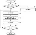
도 4는 본 개시의 실시 예에 따른 영상 처리 방법 중 프리뷰 모드 지원을 위한 전자 장치 제어 방법을 설명하기 위한 도면이다.4 is a diagram for explaining an electronic device control method for supporting a preview mode among image processing methods according to an embodiment of the present disclosure.
도 4를 참조하면, 본 개시의 프리뷰 영상 처리를 위한 전자 장치 제어 방법은 먼저 단말기(100)의 제어부(160)가 기 설정된 스케줄 정보에 의해 발생된 이벤트 또는 입력부(120)나 표시부(140)로부터 입력된 이벤트를 수신할 수 있다. 예컨대 제어부(160)는 영상 수집을 요청하는 입력 신호를 입력부(120)의 키 입력에 의해 수신하거나 표시부(140)의 터치 이벤트로서 수신할 수 있다. 그러면 제어부(160)는 401 동작(Operation)에서 수신된 이벤트가 이미지 센서(110)의 프리뷰 모드 활성화를 위한 이벤트인지 확인할 수 있다. 이 동작에서 수신된 이벤트가 이미지 센서(110)와 관련이 없는 이벤트인 경우 제어부(160)는 403 동작에서 해당 이벤트에 따른 기능 수행을 지원할 수 있다. 예컨대 제어부(160)는 음성 통화 기능, 데이터 통신 기능, 방송 수신 기능, 메시지 기능, 파일 재생 기능, 파일 편집 기능, 갤러리 기능 등 이벤트 특성에 따른 기능 수행을 지원할 수 있다.Referring to FIG. 4, an electronic device control method for preview image processing according to the present invention comprises: an event generated by a
401 동작에서 발생한 이벤트가 이미지 센서(110) 운용과 관련된 이벤트인 경우 제어부(160)는 이미지 센서(110) 활성화를 수행하고, 프리뷰 모드 지원을 위하여 405 동작에서 제1 영상 예컨대 센서 영상 획득을 제어할 수 있다. 이 동작에서 제어부(160)는 이미지 센서(110)의 전원 공급과, 사전 정의된 센서 설정에 따른 이미지 센서(110) 환경 제어를 수행할 수 있다. 특히 제어부(160)는 이미지 센서(110) 활성화 시 디폴트로 프리뷰 영상을 지원하도록 설정된 경우 프리뷰 모드를 디폴트로 지원할 수 있다.When the event occurring in the
본 개시의 일 실시예 따르면, 제어부(160)는 활성화된 이미지 센서(110)가 피사체에 대한 센서 영상을 획득하여 제공하면, 407 동작에서 설정된 매핑 정보 기반으로 출력 장치와 호환되는 제2 영상 생성을 제어할 수 있다. 예컨대 제어부(160)는 제1 영상을 사전 정의된 매핑 정보를 기반으로 표시부(140)와 호환되는 프리뷰 영상 생성을 수행하도록 제어할 수 있다. 예컨대, 제어부(160)는 이미지 센서(110)가 제공하는 센서 베이어 패턴으로 획득된 센서 영상을 매핑 정보(166)에 의해 표시부 베이어 패턴으로 변환하도록 제어할 수 있다. 그리고 제어부(160)는 409 동작에서 표시부 베이어 패턴으로 변환된 영상을 제2 영상 예컨대 프리뷰 영상으로 표시부(140)에 출력하도록 제어할 수 있다. 이 동작을 수행하면서 제어부(160)는 센서 영상에 대한 전처리 동작을 수행할 수 있다. 또한 제어부(160)는 표시부 베이어 패턴으로 변환된 영상에 대한 후처리 동작을 수행할 수 있다. 전처리 동작 및 후처리 동작은 각각 센서 영상 및 프리뷰 영상에 대한 영상 에러를 정정하거나 보다 선명하게 또는 명확하게 표시될 수 있도록 처리하는 동작이 될 수 있다.According to one embodiment of the present disclosure, when the activated
제어부(160)는 411 동작에서 기능 종료를 위한 이벤트 발생 여부를 확인할 수 있다. 그리고 별도의 기능 종료를 위한 이벤트 발생이 없으면 605 동작 이전으로 분기하여 이하 동작을 재수행하도록 제어할 수 있다.The
상술한 바와 같이 제어부(160)는 센서 베이어 패턴과 동일한 타입의 베이어 패턴을 가지는 프리뷰 영상을 생성하여 출력할 수 있다. 이에 따라 본 개시의 제어부(160)는 센서 영상에 대한 특성 추출, 추출 특성에 대한 타입 변환, 변환된 타입의 신호 처리, 신호 처리된 영상의 타입 재변환 등의 동작 중 적어도 하나의 동작을 수행하지 않을 수 있다. 결과적으로 제어부(160)는 센서 영상으로부터 보다 간소화된 영상 처리 방식을 기반으로 프리뷰 영상을 생성하고 출력하도록 지원할 수 있다.As described above, the
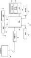
도 5는 본 개시의 실시 예에 따른 영상 처리 기능을 지원하는 영상 처리 시스템의 구성을 개략적으로 나타낸 도면이다.5 is a diagram schematically illustrating a configuration of an image processing system supporting an image processing function according to an embodiment of the present disclosure.
도 5를 참조하면, 본 개시의 영상 처리 시스템(10)은 전자 장치 예컨대 단말기(100) 및 단말기(100)와 연결되는 외부 표시 장치(200)의 구성을 포함할 수 있다. 여기서 영상 처리 시스템(10)은 단말기(100)의 표시부(140) 및 외부 표시 장치(200)를 각각 이미지 출력을 위한 출력 장치로 포함할 수 있다.5, the image processing system 10 of the present disclosure may include a configuration of an
이러한 영상 처리 시스템(10)은 단말기(100)에 마련된 접속 인터페이스(130)를 통하여 외부 표시 장치(200)가 연결될 수 있다. 이와 같은 구성의 영상 처리 시스템(10)은 이미지 센서(110)가 획득한 센서 영상으로부터 외부 표시 장치(200)에 출력할 외부 출력 프리뷰 영상을 생성하여 출력할 수 있다. 이때 본 개시의 영상 처리 시스템(10)은 외부 표시 장치(200)의 표시 특성 확인을 수행하고 그에 대응하는 매핑 정보를 선택할 수 있다. 그리고 영상 처리 시스템(10)은 선택된 매핑 정보를 기반으로 센서 영상으로부터 외부 출력 프리뷰 영상을 생성하여 외부 표시 장치(200)에 출력하도록 지원할 수 있다. 결과적으로 영상 처리 시스템(10)은 다양한 매핑 정보 중 외부 표시 장치(200)에 최적화된 매핑 정보를 활용함으로써 최적의 외부 출력 프리뷰 영상 출력을 지원할 수 있다.The image processing system 10 may be connected to the
본 개시의 일 실시예에 따르면, 단말기(100)는 도시된 바와 같이 이미지 센서(110), 입력부(120), 접속 인터페이스(130), 표시부(140), 저장부(150) 및 제어부(160) 구성을 포함할 수 있다. 그리고 단말기(100)는 통신부(170) 구성을 더 포함할 수 있다. 이와 같은 구성은 앞서 도 1에서 설명한 구성들과 유사한 기능을 적어도 일부 지원할 수 있다. 이에 따라, 이하 설명에서는 본 개시의 영상 처리 시스템(10)에서의 프리뷰 영상 처리를 위한 기능 부분에 대해서 보다 상세히 설명하기로 한다.According to one embodiment of the present disclosure, a terminal 100 includes an
본 개시의 일 실시예에 따르면, 이미지 센서(110)는 제어부(160) 제어에 따라 활성화되어 피사체에 대한 센서 베이어 패턴의 센서 영상을 수집할 수 있다. 그리고 이미지 센서(110)는 센서 영상을 제어부(160)에 제공할 수 있다. 이미지 센서(110)는 앞서 설명한 바와 같이 설계된 방식에 따라 RGB 타입 또는 RGBW 타입 등 특정 베이어 패턴의 센서 영상을 수집하여 제공할 수 있다.According to one embodiment of the present disclosure, the
본 개시의 일 실시예에 따르면, 입력부(120)는 이미지 센서(110) 활성화를 위한 입력 신호, 본 개시의 프리뷰 모드 활성화를 위한 입력 신호 등을 생성할 수 있다. 또한 입력부(120)는 단말기(100) 제어와 관련된 다양한 입력 신호를 생성할 수 있다. 특히 입력부(120)는 접속 인터페이스(130)를 통하여 외부 표시 장치(200)가 접속되면 외부 표시 장치(200) 지원을 위한 특정 매핑 정보 선택 신호를 생성할 수 있다. 후술하겠지만 제어부(160)는 접속 인터페이스(130)에 외부 표시 장치(200)가 접속되면 외부 표시 장치(200)의 종류를 확인하고 그에 따른 매핑 정보가 자동 선택되도록 지원할 수 있다. 다만 특정 외부 표시 장치(200)의 경우에는 최적의 매핑 정보 선택이 자동으로 제공되지 않을 수도 있다. 이 경우 제어부(160)는 외부 표시 장치(200)에 외부 출력 프리뷰 영상을 제공하기 위한 매핑 정보 선택을 위한 화면을 제공할 수 있다. 그러면 사용자는 입력부(120) 또는 입력 기능의 표시부(140)를 이용하여 수동으로 특정 매핑 정보 선택을 수행할 수 있다.According to one embodiment of the present disclosure, the
본 개시의 일 실시예에 따르면, 접속 인터페이스(130)는 외부 표시 장치(200)가 접속되도록 지원할 수 있다. 예컨대 접속 인터페이스(130)는 외부 표시 장치(200)와 케이블 등의 유선 연결을 지원하는 유선 접속 인터페이스를 포함할 수 있다. 또한 접속 인터페이스(130)는 외부 표시 장치(200)와 무선으로 데이터를 전송할 수 있는 무선 접속 인터페이스를 포함할 수 있다. 이에 따라 접속 인터페이스(130)는 USB나 UART와 같은 직렬 인터페이스뿐만 아니라, 근거리 무선 통신 모듈의 형태로 마련될 수도 있다. 한편 접속 인터페이스(130)에 외부 표시 장치(200)가 연결되면 접속 인터페이스(130)는 외부 표시 장치(200) 접속에 따른 신호를 제어부(160)에 전달할 수 있다.According to one embodiment of the present disclosure, the
본 개시의 일 실시예에 따르면, 표시부(140)는 단말기(100) 운용과 관련된 다양한 화면을 출력할 수 있다. 이러한 표시부(140)는 이미지 센서(110) 활성화 선택을 위한 메뉴 화면이나 아이콘 화면을 출력할 수 있다. 그리고 표시부(140)는 이미지 센서(110)가 활성화되면 이미지 센서(110) 환경 설정을 위한 제어 화면을 출력할 수 있다. 표시부(140)는 이미지 센서(110)가 획득한 센서 영상으로부터 제1 매핑 정보를 적용하여 생성된 프리뷰 영상을 출력할 수 있다. 이때 제1 매핑 정보는 표시부 베이어 패턴에 센서 영상을 최적화하기 위한 매핑 정보가 될 수 있다. 한편 표시부(140)는 접속 인터페이스(130)에 외부 표시 장치(200)가 접속되는 경우 자동으로 턴??오프될 수 있다. 또는 표시부(140)는 스케줄 정보에 따라 또는 사용자 제어에 따라 외부 표시 장치(200)의 접속과는 독립적으로 턴??온 상태를 유지하거나 턴??오프될 수도 있다.According to an embodiment of the present disclosure, the
본 개시의 일 실시예에 따르면, 저장부(150)는 단말기(100) 운용에 필요한 프로그램과 데이터를 저장할 수 있다. 특히 저장부(150)는 앞서 설명한 영상 처리 프로그램(151)을 저장할 수 있다. 또한 저장부(150)는 다수의 표시 장치에 프리뷰 영상을 출력하기 위해 다수의 매핑 정보를 포함한 매핑 테이블(153)을 포함할 수 있다. 도 1에서 설명한 영상 처리 프로그램(151)과 비교하여 도 5에서 설명하는 영상 처리 프로그램(151)은 접속 인터페이스(130)를 통하여 접속되는 외부 표시 장치(200)에 출력할 외부 출력 프리뷰 영상 생성과 출력을 지원하는 루틴을 더 포함할 수 있다. 예컨대, 영상 처리 프로그램(151)은 표시부(140)를 통한 프리뷰 영상 출력을 지원하는 표시부 출력 루틴 및 외부 표시 장치(200)를 통하여 외부 출력 프리뷰 영상 처리를 지원하는 외부 표시 장치 출력 루틴을 포함할 수 있다. 표시부 출력 루틴은 앞서 도 1에서 설명한 영상 처리 프로그램(151)의 루틴들을 포함할 수 있다. 외부 표시 장치 출력 루틴은 프리뷰 모드에서 외부 표시 장치(200) 접속을 확인하는 루틴, 외부 표시 장치(200) 종류 확인 루틴을 포함할 수 있다. 또한 외부 표시 장치 출력 루틴은 외부 표시 장치(200)로 출력될 외부 출력 프리뷰 영상 생성을 위한 제2 매핑 정보 선택 루틴, 제2 매핑 정보 기반으로 외부 출력 프리뷰 영상을 생성하는 루틴, 생성된 외부 출력 프리뷰 영상을 출력하는 루틴을 포함할 수 있다.According to one embodiment of the present disclosure, the
본 개시의 일 실시예에 따르면, 제어부(160)는 이미지 센서(110)의 프리뷰 모드 지원 시 접속 인터페이스(130)에 외부 표시 장치(200) 접속에 따른 외부 출력 프리뷰 영상 생성과 출력을 제어할 수 있다. 이를 보다 상세히 설명하면, 제어부(160)는 외부 표시 장치(200)가 접속 인터페이스(130)에 접속되면 외부 표시 장치(200)의 종류 예컨대 장치 ID 정보를 확인할 수 있다. 또는 제어부(160)는 외부 표시 장치(200)가 어떠한 베이어 패턴을 가지는지를 확인할 수 있다. 그리고 제어부(160)는 해당 장치 ID 정보 또는 베이어 패턴 정보에 대응하는 매핑 정보를 매핑 테이블(153)에서 검색할 수 있다. 이를 이하여 매핑 테이블(153)에 저장된 매핑 정보들은 장치 ID 정보별로 저장되거나, 베이어 패턴 정보별로 저장될 수 있다. 여기서 매핑 정보는 센서 영상으로부터 표시부(140) 또는 외부 표시 장치(200)의 하드웨어 특성에 맞도록 최적화된 외부 출력 프리뷰 영상을 생성하기 위한 매핑 알고리즘을 포함할 수 있다.According to one embodiment of the present disclosure, the
본 개시의 일 실시예에 따르면, 제어부(160)는 외부 표시 장치(200)에 맞는 매핑 정보를 선택하고, 선택된 매핑 정보를 기반으로 센서 영상으로부터 외부 출력 프리뷰 영상을 생성할 수 있다. 그리고 제어부(160)는 생성된 외부 출력 프리뷰 영상을 접속 인터페이스(130)를 통하여 외부 표시 장치(200)에 출력하도록 지원할 수 있다. 이에 따라 외부 표시 장치(200)는 이미지 센서(110)가 획득한 센서 영상으로부터 생성된 외부 출력 프리뷰 영상을 출력할 수 있다.According to an embodiment of the present disclosure, the
본 개시의 일 실시예에 따르면, 제어부(160)는 외부 표시 장치(200)와 독립적으로 표시부(140)에 프리뷰 영상을 출력하도록 요청받을 수 있다. 이 경우, 제어부(160)는 표시부(140)의 프리뷰 영상 지원을 위한 제1 매핑 정보를 기준으로 센서 영상으로부터 프리뷰 영상을 생성할 수 있다. 그리고 제어부(160)는 생성된 프리뷰 영상을 표시부(140)에 출력하도록 제어할 수 있다. 이에 따라 제어부(160)는 스케줄 정보에 따라 또는 입력 요청에 따라 표시부(140)와 외부 표시 장치(200)에 동시 프리뷰 영상 출력을 지원할 수 있다. 또는 제어부(160)는 이벤트 발생에 따라 표시부(140) 또는 외부 표시 장치(200) 중 어느 하나에 프리뷰 영상 출력을 지원할 수 있다.According to an embodiment of the present disclosure, the
본 개시의 일 실시예에 따르면, 통신부(170)는 단말기(100)의 통신 기능을 지원하는 구성이다. 통신부(170)는 매핑 테이블(153)의 갱신 또는 매핑 정보 검색을 지원할 수 있다. 예컨대 통신부(170)는 일정 주기로 또는 특정 이벤트에 따라 외부 서버 장치로부터 매핑 정보를 수신할 수 있다. 통신부(170)가 수신한 매핑 정보는 제어부(160)에 전달되고, 제어부(160)는 수신된 매핑 정보를 이용하여 저장부(150)에 저장된 매핑 테이블(153) 갱신을 수행할 수 있다. 또한 통신부(170)는 외부 표시 장치(200)가 제공한 장치 ID 또는 베이어 패턴에 최적화된 매핑 정보 검색을 지원할 수 있다. 이를 위하여 통신부(170)는 매핑 정보를 제공하는 외부 서버 장치와 자동으로 또는 사용자 요청에 따라 통신 채널을 형성할 수 있다. 그리고 통신부(170)는 제어부(160) 제어에 따라 장치 ID 또는 베이어 패턴 정보를 외부 서버 장치에 제공할 수 있다. 외부 서버 장치가 해당 장치 ID 또는 베이어 패턴 정보에 대응하는 매핑 정보를 제공하면, 통신부(170)는 이를 수신하여 제어부(160)에 제공할 수 있다. 이에 따라 제어부(160)는 접속 인터페이스(130)를 통해 접속된 외부 표시 장치(200)에 최적화된 매핑 정보를 실시간 검색 및 적용을 수행할 수 있다.According to one embodiment of the present disclosure, the
본 개시의 일 실시예에 따르면, 외부 표시 장치(200)는 접속 인터페이스(130)를 통하여 단말기(100)에 접속될 수 있는 장치가 될 수 있다. 이러한 외부 표시 장치(200)는 단말기(100)와 통신 채널을 유무선 중 적어도 하나의 방식으로 형성할 수 있다. 그리고 외부 표시 장치(200)는 형성된 통신 채널을 통하여 단말기(100)로부터 프리뷰 영상을 수신하여 출력할 수 있다. 외부 표시 장치(200)는 접속 인터페이스(130)를 통하여 단말기(100)에 자신의 장치 ID 정보 또는 표시 장치의 베이어 패턴 정보를 제공할 수 있다. 그리고 외부 표시 장치(200)는 자신이 제공한 정보에 최적화된 외부 출력 프리뷰 영상을 수신하여 실시간 출력하도록 지원할 수 있다. 이러한 외부 표시 장치(200)는 일례로서 TV 모니터, 스마트 TV, 테블릿 PC, 슬레이트 PC, 패드형 또는 노트형 PC 등 표시 패널을 가지는 전자 장치가 될 수 있다.According to one embodiment of the present disclosure, the
도 6은 본 개시의 실시 예에 따른 영상 처리 방법 중 프리뷰 모드를 지원하는 시스템에서의 전자 장치 제어 방법을 설명하기 위한 순서도이다.6 is a flowchart for explaining a method of controlling an electronic device in a system supporting a preview mode among image processing methods according to an embodiment of the present disclosure.
도 6을 참조하면, 본 개시의 프리뷰 모드를 지원하는 시스템에서 전자 장치의 제어 방법은 먼저 단말기(100)의 제어부(160)가 스케줄 정보에 따른 특정 이벤트 또는 입력부(120)나 표시부(140) 등의 입력 수단으로부터 발생한 입력 이벤트를 수신할 수 있다. 그러면 제어부(160)는 601 동작에서 수신된 이벤트가 이미지 센서(110)의 프리뷰 모드 활성화를 위한 이벤트인지 확인할 수 있다.6, a control method of an electronic device in a system supporting the preview mode of the present invention includes a step of displaying a specific event according to schedule information or a specific event according to schedule information, Can receive the input event generated from the input means of the input device. Then, the
여기서 제어부(160)는 수신된 이벤트가 프리뷰 모드와 관련이 없는 경우, 해당 이벤트 종류 및 특성에 따른 단말기(100) 기능이 수행되도록 지원할 수 있다. 예컨대 제어부(160)는 사진 편집 기능, 배경 화면 변경 기능, 파일 재생 기능, 통신 기능 등을 지원할 수 있다.Here, if the received event is not related to the preview mode, the
한편 603 동작에서 프리뷰 모드 지원을 요청받는 경우 제어부(160)는 605 동작에서 프리뷰 영상을 출력할 장치 확인을 수행할 수 있다. 예컨대, 제어부(160)는 접속 인터페이스(130)에 외부 표시 장치(200)가 접속되어 있는지 확인할 수 있다. 또한 제어부(160)는 접속된 외부 표시 장치(200)로 외부 출력 프리뷰 영상을 출력하도록 하는 이벤트 수신을 확인할 수 있다. 여기서 외부 표시 장치(200)가 접속 인터페이스(130)에 접속 시 디폴트로 외부 출력 프리뷰 영상을 출력하도록 설계된 경우 이벤트 수신 확인 동작은 생략될 수 있다. 이하 동작에서는 외부 표시 장치(200)가 접속 인터페이스(130)에 접속되고, 해당 외부 표시 장치(200)에 외부 출력 프리뷰 영상을 출력하도록 요청받은 상태를 기준으로 설명하기로 한다.On the other hand, when the preview mode support is requested in
본 개시의 일 실시예에 따르면, 외부 표시 장치(200)에 외부 출력 프리뷰 영상을 출력하도록 요청받으면 제어부(160)는 607 동작에서 센서 영상 획득을 지원할 수 있다. 그리고 제어부(160)는 센서 영상을 외부 표시 장치(200)에 출력할 외부 출력 프리뷰 영상으로 변환하기 위해 609 동작에서 매핑 정보 선택을 수행할 수 있다. 이때 제어부(160)는 외부 표시 장치(200)의 식별 정보를 기반으로 매칭되는 매핑 정보를 매핑 테이블(153)에서 검색할 수 있다. 한편 상술한 동작에서 센서 영상 획득 동작과 외부 표시 장치(200)에 적용할 매핑 정보 선택 동작은 독립적으로 수행될 수도 있다. 따라서 센서 영상 획득 동작 및 매핑 정보 선택 동작은 동시에 수행될 수 있다.According to an embodiment of the present disclosure, when the
한편 외부 출력 프리뷰 영상에 적용할 매핑 정보가 선택되면, 제어부(160)는 611 동작에서 선택 매핑 정보를 기반으로 외부 출력 프리뷰 영상을 생성할 수 있다. 선택 매핑 정보 기반의 외부 출력 프리뷰 영상 생성 동작은 앞서 도 3에서 설명한 바와 같이 센서 베이어 패턴의 센서 영상을 외부 표시 장치의 베이어 패턴에 맞도록 변환하는 동작이 될 수 있다.On the other hand, if the mapping information to be applied to the external output preview image is selected, the
다음으로 제어부(160)는 613 동작에서 외부 출력 프리뷰 영상을 접속 인터페이스(130)를 통하여 외부 표시 장치(200)에 전달할 수 있다. 제어부(160)는 이 동작에서 615 동작에서 프리뷰 모드 종료를 위한 입력 신호 발생 이전까지 반복적으로 수행할 수 있다.Next, the
이상에서 설명한 바와 같이 본 개시의 실시 예에 따른 영상 처리 방법 및 시스템과 이를 지원하는 전자 장치에 따르면, 본 개시는 이미지 센서(110)가 획득한 센서 영상에 대해 보다 간소화된 절차를 통한 프리뷰 영상 생성을 수행할 수 있다. 이에 따라 본 개시는 센서 영상 처리를 위한 하드웨어 장치를 보다 간소화할 수 있으며 그에 다른 물리적인 공간 확보를 가능케 할 수 있다. 또한 본 개시는 센서 영상 처리에서의 부하를 감소시켜 전자 장치의 운용 효율을 개선할 수 있다.As described above, according to the image processing method and system and the electronic apparatus supporting the image processing method according to the embodiment of the present disclosure, the present disclosure relates to an image processing method and system for generating a preview image through a simplified procedure for a sensor image acquired by the
본 개시의 일 실시예에 따르면, 프리뷰 모드를 지원하는 이미지 센서(110)의 획득 영상의 베이어 패턴은 상술한 RGB/RGBW 패턴에 한정되는 것은 아니다. 예컨대, 이미지 센서(110)의 설계 방식이나 형태 변경에 따라 보다 다양한 형태가 될 수 있다. According to one embodiment of the present disclosure, the Bayer pattern of the acquired image of the
본 개시의 일 실시예에 따르면, 이미지 센서(110)는 피사체 영상을 직접 처리하여 상술한 프리뷰 영상을 생성 후 제어부(160)에 전달할 수도 있다. 이를 위하여 이미지 센서(110)는 영상 처리를 위하여 영상 처리 모듈을 포함할 수 있다. 예컨대, 상술한 제어부(160) 구성 중 전처리부(161), 매핑부(163) 및 후처리부(165)의 구성이 이미지 센서(110)의 구성으로 포함될 수 있다. 이 경우 이미지 센서(110)는 상술한 구성들을 모두 포함하는 통합 모듈의 의미로 이해될 수 있을 것이다. 이와 같은 구성의 이미지 센서(110)에 포함된 매핑부(163)는 매핑 정보를 임베이디드 타입 또는 미들웨어 타입으로 탑재할 수 있다. 그리고 이미지 센서(110)는 해당 매핑 정보를 기반으로 프리뷰 영상을 생성하여 제어부(160)에 전달할 수 있다. 이때 제어부(160)는 이미지 센서(110)가 제공한 프리뷰 영상을 별도의 처리 동작 없이 표시부(140)에 출력하는 기능만을 제어할 수 있을 것이다. According to an embodiment of the present disclosure, the
본 개시의 일 실시예에 따르면, 상술한 단말기(100)는 그 제공 형태에 따라 다양한 추가 모듈을 더 포함할 수 있다. 예컨대, 상기 단말기(100)는 상기 단말기(100)의 유선통신방식 또는 무선통신방식에 의한 데이터 송수신을 위한 인터페이스, 인터넷 네트워크와 통신하여 인터넷 기능을 수행하는 인터넷통신모듈 등과 같이 상기에서 언급되지 않은 구성들을 더 포함할 수도 있다. 이러한 구성 요소들은 디지털 기기의 컨버전스(convergence) 추세에 따라 변형이 매우 다양하여 모두 열거할 수는 없으나, 상기 언급된 구성 요소들과 동등한 수준의 구성 요소가 상기 디바이스에 추가로 더 포함되어 구성될 수 있다. 또한 본 개시의 단말기(100)는 그 제공 형태에 따라 상기한 구성에서 특정 구성들이 제외되거나 다른 구성으로 대체될 수도 있음은 물론이다. 이는 본 기술분야의 통상의 지식을 가진 자에겐 쉽게 이해될 수 있을 것이다. According to one embodiment of the present disclosure, the above-described
또한 본 개시의 실시 예에 따른 상기 단말기(100)는 예컨대, 다양한 통신 시스템들에 대응되는 통신 프로토콜들(communication protocols)에 의거하여 동작하는 모든 이동통신 단말기들(mobile communication terminals)을 비롯하여, PMP(Portable Multimedia Player), 디지털방송 플레이어, PDA(Personal Digital Assistant), 음악 재생기(예컨대, MP3 플레이어), 휴대게임단말, 스마트 폰(Smart Phone), 노트북(Notebook) 및 핸드헬드 PC 등 모든 정보통신기기와 멀티미디어 및 그에 대한 응용기기를 포함할 수 있다.Also, the terminal 100 according to an embodiment of the present disclosure may include, for example, all mobile communication terminals operating based on communication protocols corresponding to various communication systems, A portable game terminal, a smart phone, a notebook computer, and a handheld PC), a digital multimedia player, a portable digital multimedia player, a digital broadcasting player, a PDA (Personal Digital Assistant), a music player Multimedia and application devices therefor.
한편, 본 명세서와 도면을 통해 본 개시의 바람직한 실시 예들에 대하여 설명하였으며, 비록 특정 용어들이 사용되었으나, 이는 단지 본 개시의 기술 내용을 쉽게 설명하고 기술의 특징 이해를 돕기 위한 일반적인 의미에서 사용된 것일 뿐, 본 개시의 범위를 한정하고자 하는 것은 아니다. 여기에 개시된 실시 예외에도 본 개시의 기술적 사상에 바탕을 둔 다른 변형 예들이 실시 가능하다는 것은 본 개시가 속하는 기술분야에서 통상의 지식을 가진 자에게 자명한 것이다.While preferred embodiments of the present disclosure have been described and illustrated, it should be understood that the terminology used herein is for the purpose of describing particular embodiments only and is not intended to be limiting of the present invention. However, it is not intended to limit the scope of the present disclosure. It will be apparent to those skilled in the art that other modifications based on the technical idea of the present disclosure are possible in the exemplary embodiments disclosed herein.
100 : 단말기110 : 이미지 센서
120 : 입력부130 : 접속 인터페이스
140 : 표시부150 : 저장부
160 : 제어부170 : 통신부
200 : 외부 표시 장치100: terminal 110: image sensor
120: input unit 130: connection interface
140: Display unit 150:
160: control unit 170:
200: External display device
Claims (20)
Translated fromKorean이미지 센서를 사용하여 제 1 영상을 획득하는 동작;
사전 정의된 매핑 정보를 기반으로 상기 제 1 영상으로부터 출력장치와 호환되는 제 2 영상을 생성하는 생성 동작;
상기 제 2 영상을 상기 출력 장치에 출력하는 동작을 포함하는 영상 처리 방법.A method of operating an electronic device,
Acquiring a first image using an image sensor;
Generating a second image compatible with the output device from the first image based on the predefined mapping information;
And outputting the second image to the output apparatus.
상기 생성 동작은
상기 제 1 영상의 베이어 패턴을 상기 출력 장치의 베이어 패턴에 상기 사전 정의된 매핑 정보를 기반으로 매핑하는 매핑 동작을 포함하는 영상 처리 방법.The method according to claim 1,
The generating operation
And mapping the Bayer pattern of the first image to the Bayer pattern of the output device based on the predefined mapping information.
상기 생성 동작은
상기 제1 영상의 베이어 패턴을 상기 출력 장치의 베이어 패턴에 매핑하되 다운스케일 매핑하는 매핑 동작;
상기 다운스케일 매핑된 영상에 후처리를 수행하는 동작;을 더 포함하는 영상 처리 방법.3. The method of claim 2,
The generating operation
A mapping operation of mapping a Bayer pattern of the first image to a Bayer pattern of the output device, but downscaling the mapping;
And performing post-processing on the downscaled mapped image.
상기 매핑 동작은
상기 제1 영상의 베이어 패턴에 포함된 복수개의 서브 픽셀의 색상도 평균치를 상기 출력 장치의 하나의 서브 픽셀의 색상 값으로 매핑하는 동작;을 포함하는 영상 처리 방법.3. The method of claim 2,
The mapping operation
And mapping an average of hue values of a plurality of subpixels included in the Bayer pattern of the first image to a hue value of one subpixel of the output device.
상기 매핑 동작은
상기 제1 영상의 베이어 패턴에 포함된 복수개의 서브 픽셀 중 가장 큰 색상 값을 상기 출력 장치의 하나의 서브 픽셀 색상 값으로 매핑하는 동작;을 포함하는 영상 처리 방법.3. The method of claim 2,
The mapping operation
And mapping the largest color value among the plurality of subpixels included in the Bayer pattern of the first image to one subpixel color value of the output apparatus.
상기 매핑 동작은
상기 제1 영상의 영역별 특성에 따라 매핑 방식을 다르게 적용하는 동작;을 포함하는 영상 처리 방법.3. The method of claim 2,
The mapping operation
And applying the mapping scheme differently according to the region-specific characteristics of the first image.
상기 매핑 동작은
상기 제1 영상에 포함된 경계 영역과 비 경계 영역의 다운스케일 방식을 다르게 적용하는 동작인 영상 처리 방법.The method according to claim 6,
The mapping operation
And applying the downscale method of the boundary region and the non-boundary region included in the first image differently.
상기 생성 동작은
상기 제1 영상을 메모리에 저장하는 동작;
상기 매핑 정보를 확인하는 동작;
상기 매핑 정보를 기반으로 상기 제1 영상으로부터 상기 제2 영상을 생성하여 상기 메모리에 저장하는 동작;을 포함하는 영상 처리 방법.The method according to claim 1,
The generating operation
Storing the first image in a memory;
Confirming the mapping information;
And generating the second image from the first image based on the mapping information and storing the second image in the memory.
적어도 하나의 매핑 정보를 저장하는 저장부;
상기 제 1 영상으로부터 생성된 제 2 영상을 제어에 따라 선택적으로 출력하는 표시부;
상기 매핑 정보를 기반으로 상기 제 1 영상으로부터 상기 제 2 영상을 생성하고 상기 표시부에 상기 제 2 영상을 출력하도록 제어하는 제어부를 포함하는 전자 장치.An image sensor for acquiring a first image;
A storage unit for storing at least one mapping information;
A display unit for selectively outputting a second image generated from the first image according to a control;
And a controller for generating the second image from the first image based on the mapping information and outputting the second image to the display unit.
상기 매핑 정보는,
상기 제 1 영상의 베이어 패턴을 상기 표시부와 호환되는 베이어 패턴에 매핑한 정보를 포함하는 전자 장치.10. The method of claim 9,
The mapping information includes:
And information obtained by mapping the Bayer pattern of the first image to a Bayer pattern compatible with the display unit.
적어도 하나의 외부 표시 장치가 접속되는 접속 인터페이스;를 포함하고,
상기 접속 인터페이스는
상기 외부 표시 장치와 유선으로 접속되는 유선 통신 인터페이스;
상기 외부 표시 장치와 무선으로 접속되는 유선 통신 인터페이스; 중 적어도 하나를 포함하는 전자 장치.10. The method of claim 9,
And a connection interface to which at least one external display device is connected,
The connection interface
A wired communication interface wired to the external display device;
A wired communication interface wirelessly connected to the external display device; ≪ / RTI >
상기 저장부는
상기 외부 표시 장치별 적용할 매핑 정보들을 포함하는 매핑 테이블을 저장하는 전자 장치.11. The method of claim 10,
The storage unit
And a mapping table including mapping information to be applied to the external display device.
상기 제어부는
상기 접속 인터페이스에 접속된 외부 표시 장치의 식별 정보를 수집하고, 상기 식별 정보에 대응하는 매핑 정보를 검색하여 상기 외부 표시 장치에 출력할 외부 출력 프리뷰 영상을 생성하는 전자 장치.13. The method of claim 12,
The control unit
Acquires identification information of an external display device connected to the connection interface, searches mapping information corresponding to the identification information, and generates an external output preview image to be output to the external display device.
상기 표시부는
상기 접속 인터페이스에 외부 표시 장치 접속 시 상기 제2 영상 출력을 자동으로 중지하는 전자 장치.13. The method of claim 12,
The display unit
And automatically stops the second video output when the external display device is connected to the connection interface.
상기 표시부는
접속된 적어도 하나의 외부 표시 장치의 외부 출력 프리뷰 영상 출력과 독립적으로 제2 영상을 출력하는 전자 장치.13. The method of claim 12,
The display unit
And outputs the second image independently of the external output preview video output of the connected at least one external display device.
갱신된 매핑 정보 수신을 위한 통신부;를 더 포함하는 전자 장치.11. The method of claim 10,
And a communication unit for receiving the updated mapping information.
상기 제어부는
상기 외부 표시 장치에 적용할 매핑 정보 부재 시 상기 통신부를 통하여 외부 서버 장치로부터 상기 외부 표시 장치에 적용할 매핑 정보를 수집하는 전자 장치.17. The method of claim 16,
The control unit
And acquires mapping information to be applied to the external display device from the external server device through the communication unit when mapping information to be applied to the external display device is absent.
상기 제어부는
상기 이미지 센서가 획득한 상기 제1 영상의 전처리 수행을 위한 전처리부;
상기 매핑 정보 기반으로 패턴 변환을 수행하는 매핑부;
상기 패턴 변환이 적용된 영상의 후처리를 수행하는 후처리부;
상기 전처리, 상기 패턴 변환 및 상기 후처리를 수행을 위한 메모리;
상기 영상 처리를 위한 연산 및 조정을 수행하는 연산부;를 포함하는 전자 장치.10. The method of claim 9,
The control unit
A preprocessing unit for pre-processing the first image acquired by the image sensor;
A mapping unit for performing pattern conversion based on the mapping information;
A post-processing unit for post-processing the image to which the pattern conversion is applied;
A memory for performing the pre-processing, the pattern conversion, and the post-processing;
And an arithmetic unit for performing arithmetic operation and adjustment for the image processing.
이미지 센서를 사용하여 제 1 영상을 획득하는 영상획득 모듈;
사전 정의된 매핑 정보를 기반으로 상기 제 1 영상으로부터 출력장치와 호환되는 제 2 영상을 생성하는 생성 모듈;
상기 제 2 영상을 상기 출력 장치에 출력하는 출력 모듈을 포함하는 전자 장치.In an electronic device,
An image acquisition module for acquiring a first image using an image sensor;
A generation module for generating a second image compatible with the output device from the first image based on the predefined mapping information;
And an output module for outputting the second image to the output device.
상기 표시부의 베이어 패턴에 해당하는 매핑 정보를 기반으로 상기 제1 영상으로부터 생성된 프리뷰 영상을 출력하는 표시부;를 더 포함하는 전자 장치.20. The method of claim 19,
And a display unit for outputting a preview image generated from the first image based on mapping information corresponding to the Bayer pattern of the display unit.
Priority Applications (3)
| Application Number | Priority Date | Filing Date | Title |
|---|---|---|---|
| KR1020130043853AKR20140125984A (en) | 2013-04-19 | 2013-04-19 | Image Processing Method, Electronic Device and System |
| US14/242,184US20140313366A1 (en) | 2013-04-19 | 2014-04-01 | Method of processing image and electronic device and system supporting the same |
| PCT/KR2014/003172WO2014171675A1 (en) | 2013-04-19 | 2014-04-14 | Method of processing image and electronic device and system supporting the same |
Applications Claiming Priority (1)
| Application Number | Priority Date | Filing Date | Title |
|---|---|---|---|
| KR1020130043853AKR20140125984A (en) | 2013-04-19 | 2013-04-19 | Image Processing Method, Electronic Device and System |
Publications (1)
| Publication Number | Publication Date |
|---|---|
| KR20140125984Atrue KR20140125984A (en) | 2014-10-30 |
Family
ID=51728720
Family Applications (1)
| Application Number | Title | Priority Date | Filing Date |
|---|---|---|---|
| KR1020130043853AWithdrawnKR20140125984A (en) | 2013-04-19 | 2013-04-19 | Image Processing Method, Electronic Device and System |
Country Status (3)
| Country | Link |
|---|---|
| US (1) | US20140313366A1 (en) |
| KR (1) | KR20140125984A (en) |
| WO (1) | WO2014171675A1 (en) |
Cited By (1)
| Publication number | Priority date | Publication date | Assignee | Title |
|---|---|---|---|---|
| KR20210044755A (en)* | 2019-06-13 | 2021-04-23 | 엘지이노텍 주식회사 | Camera Device and Image Generation Method Of Camera Device |
Families Citing this family (9)
| Publication number | Priority date | Publication date | Assignee | Title |
|---|---|---|---|---|
| CN104869324A (en)* | 2015-05-18 | 2015-08-26 | 成都平行视野科技有限公司 | Image processing method and image processing system based on image software of intelligent equipment |
| CN105430358B (en)* | 2015-11-26 | 2018-05-11 | 努比亚技术有限公司 | A kind of image processing method and device, terminal |
| KR102502452B1 (en)* | 2016-02-15 | 2023-02-22 | 삼성전자주식회사 | Image sensor and method for generating restoration image |
| CN106657793B (en)* | 2017-01-11 | 2019-01-22 | 维沃移动通信有限公司 | An image processing method and mobile terminal |
| US20190139189A1 (en)* | 2017-11-06 | 2019-05-09 | Qualcomm Incorporated | Image remosaicing |
| TWI734213B (en)* | 2019-10-08 | 2021-07-21 | 勝智會科技顧問股份有限公司 | Achromatic image scanning, displaying and illuminating system |
| CN114073063B (en)* | 2020-05-27 | 2024-02-13 | 北京小米移动软件有限公司南京分公司 | Image processing methods and devices, camera components, electronic equipment, storage media |
| CN115134514B (en)* | 2021-03-29 | 2024-05-14 | 北京小米移动软件有限公司 | Image acquisition method, device and storage medium |
| WO2025146909A1 (en)* | 2024-01-03 | 2025-07-10 | 삼성전자 주식회사 | Electronic device comprising camera, and operating method therefor |
Family Cites Families (10)
| Publication number | Priority date | Publication date | Assignee | Title |
|---|---|---|---|---|
| US6205245B1 (en)* | 1998-07-28 | 2001-03-20 | Intel Corporation | Method and apparatus for rapid down-scaling of color images directly from sensor color filter array space |
| FI115587B (en)* | 2003-12-03 | 2005-05-31 | Nokia Corp | Procedures and devices for scaling down a digital matrix image |
| KR100636969B1 (en)* | 2004-12-30 | 2006-10-19 | 매그나칩 반도체 유한회사 | ISP built-in image sensor and dual camera system |
| KR100781552B1 (en)* | 2006-06-26 | 2007-12-05 | 삼성전기주식회사 | High Resolution Image Restoration Apparatus and Method |
| KR20110029217A (en)* | 2009-09-15 | 2011-03-23 | 삼성전자주식회사 | Image sensor for outputting RGB signal through internal conversion and image processing device including the same |
| EP2502115A4 (en)* | 2009-11-20 | 2013-11-06 | Pelican Imaging Corp | CAPTURE AND IMAGE PROCESSING USING A MONOLITHIC CAMERAS NETWORK EQUIPPED WITH HETEROGENEOUS IMAGERS |
| US8446484B2 (en)* | 2010-04-21 | 2013-05-21 | Nokia Corporation | Image processing architecture with pre-scaler |
| CN103563350B (en)* | 2011-05-31 | 2016-09-28 | 松下知识产权经营株式会社 | Image processing apparatus, image processing method and digital camera |
| US8634639B2 (en)* | 2011-08-03 | 2014-01-21 | Csr Technology Inc. | Zero pass JPEG bit rate controller |
| KR101238965B1 (en)* | 2011-08-29 | 2013-03-04 | 에스케이텔레시스 주식회사 | Camera combined with smart device |
- 2013
- 2013-04-19KRKR1020130043853Apatent/KR20140125984A/ennot_activeWithdrawn
- 2014
- 2014-04-01USUS14/242,184patent/US20140313366A1/ennot_activeAbandoned
- 2014-04-14WOPCT/KR2014/003172patent/WO2014171675A1/ennot_activeCeased
Cited By (1)
| Publication number | Priority date | Publication date | Assignee | Title |
|---|---|---|---|---|
| KR20210044755A (en)* | 2019-06-13 | 2021-04-23 | 엘지이노텍 주식회사 | Camera Device and Image Generation Method Of Camera Device |
Also Published As
| Publication number | Publication date |
|---|---|
| US20140313366A1 (en) | 2014-10-23 |
| WO2014171675A1 (en) | 2014-10-23 |
Similar Documents
| Publication | Publication Date | Title |
|---|---|---|
| KR20140125984A (en) | Image Processing Method, Electronic Device and System | |
| US11025814B2 (en) | Electronic device for storing depth information in connection with image depending on properties of depth information obtained using image and control method thereof | |
| US9619861B2 (en) | Apparatus and method for improving quality of enlarged image | |
| US10110806B2 (en) | Electronic device and method for operating the same | |
| US8355575B2 (en) | Image processing apparatus and image processing method | |
| US20150026632A1 (en) | Portable electronic device and display control method | |
| EP2503296B1 (en) | Energy display device, method and computer program | |
| EP3864835B1 (en) | Camera module having multi-cell structure and portable communication device including the same | |
| US9432574B2 (en) | Method of developing an image from raw data and electronic apparatus | |
| US10812699B1 (en) | Device having a camera overlaid by display and method for implementing the same | |
| CN105407295B (en) | Mobile terminal filming apparatus and method | |
| US9262062B2 (en) | Method of providing thumbnail image and image photographing apparatus thereof | |
| US9554053B1 (en) | Method and photographing apparatus for controlling function based on gesture of user | |
| KR20210053096A (en) | Method for providing preview and electronic device using the same | |
| CN106210532A (en) | One is taken pictures processing method and terminal unit | |
| US11076071B2 (en) | Device having a camera overlaid by display and method for implementing same | |
| US8018519B2 (en) | Camera module and method for personalizing on-screen display interface | |
| KR20160120469A (en) | User terminal apparatus, external device, and method for outputing audio | |
| CN107295247B (en) | Image recording apparatus and control method thereof | |
| US9100577B2 (en) | Method of providing user interface and image photographing apparatus applying the same | |
| US11775157B2 (en) | Image processing apparatus, image processing system, and control method for processing a second image with adjusting level of a first image | |
| US9247148B2 (en) | Variable-magnification image processing apparatus | |
| KR101014116B1 (en) | Method For Preview Display Control In The Camera Phone | |
| US20130163513A1 (en) | Method and device for transmitting and receiving information | |
| CN118450234A (en) | Image generation method, medium and electronic device |
Legal Events
| Date | Code | Title | Description |
|---|---|---|---|
| PA0109 | Patent application | Patent event code:PA01091R01D Comment text:Patent Application Patent event date:20130419 | |
| PG1501 | Laying open of application | ||
| PC1203 | Withdrawal of no request for examination | ||
| WITN | Application deemed withdrawn, e.g. because no request for examination was filed or no examination fee was paid |