KR20140124529A - Lighting apparatus - Google Patents
Lighting apparatusDownload PDFInfo
- Publication number
- KR20140124529A KR20140124529AKR20130042138AKR20130042138AKR20140124529AKR 20140124529 AKR20140124529 AKR 20140124529AKR 20130042138 AKR20130042138 AKR 20130042138AKR 20130042138 AKR20130042138 AKR 20130042138AKR 20140124529 AKR20140124529 AKR 20140124529A
- Authority
- KR
- South Korea
- Prior art keywords
- unit
- terminal
- light emitting
- pwm
- control
- Prior art date
- Legal status (The legal status is an assumption and is not a legal conclusion. Google has not performed a legal analysis and makes no representation as to the accuracy of the status listed.)
- Ceased
Links
- 238000005286illuminationMethods0.000claimsabstractdescription88
- 238000004891communicationMethods0.000claimsdescription111
- 238000000034methodMethods0.000claimsdescription18
- 239000000758substrateSubstances0.000claimsdescription11
- 230000005684electric fieldEffects0.000claimsdescription7
- 230000007423decreaseEffects0.000claimsdescription3
- 238000001514detection methodMethods0.000claimsdescription3
- 238000010586diagramMethods0.000description11
- 239000000470constituentSubstances0.000description4
- 230000008859changeEffects0.000description3
- 230000006870functionEffects0.000description3
- 238000009434installationMethods0.000description3
- 239000007769metal materialSubstances0.000description3
- 230000003287optical effectEffects0.000description3
- 230000008439repair processEffects0.000description3
- 238000007792additionMethods0.000description2
- 238000006243chemical reactionMethods0.000description2
- 238000013461designMethods0.000description2
- 238000009792diffusion processMethods0.000description2
- 238000012423maintenanceMethods0.000description2
- 239000000463materialSubstances0.000description2
- 239000011347resinSubstances0.000description2
- 229920005989resinPolymers0.000description2
- 101710096655Probable acetoacetate decarboxylase 1Proteins0.000description1
- 230000001413cellular effectEffects0.000description1
- 230000000694effectsEffects0.000description1
- 230000007613environmental effectEffects0.000description1
- 230000020169heat generationEffects0.000description1
- 238000004519manufacturing processMethods0.000description1
- QSHDDOUJBYECFT-UHFFFAOYSA-NmercuryChemical compound[Hg]QSHDDOUJBYECFT-UHFFFAOYSA-N0.000description1
- 229910052753mercuryInorganic materials0.000description1
- 238000012986modificationMethods0.000description1
- 230000004048modificationEffects0.000description1
- 238000012544monitoring processMethods0.000description1
- 230000008707rearrangementEffects0.000description1
- 239000004065semiconductorSubstances0.000description1
- 238000006467substitution reactionMethods0.000description1
- 238000012546transferMethods0.000description1
Images


Classifications
- F—MECHANICAL ENGINEERING; LIGHTING; HEATING; WEAPONS; BLASTING
- F21—LIGHTING
- F21V—FUNCTIONAL FEATURES OR DETAILS OF LIGHTING DEVICES OR SYSTEMS THEREOF; STRUCTURAL COMBINATIONS OF LIGHTING DEVICES WITH OTHER ARTICLES, NOT OTHERWISE PROVIDED FOR
- F21V23/00—Arrangement of electric circuit elements in or on lighting devices
- F21V23/003—Arrangement of electric circuit elements in or on lighting devices the elements being electronics drivers or controllers for operating the light source, e.g. for a LED array
- F21V23/004—Arrangement of electric circuit elements in or on lighting devices the elements being electronics drivers or controllers for operating the light source, e.g. for a LED array arranged on a substrate, e.g. a printed circuit board
- F—MECHANICAL ENGINEERING; LIGHTING; HEATING; WEAPONS; BLASTING
- F21—LIGHTING
- F21Y—INDEXING SCHEME ASSOCIATED WITH SUBCLASSES F21K, F21L, F21S and F21V, RELATING TO THE FORM OR THE KIND OF THE LIGHT SOURCES OR OF THE COLOUR OF THE LIGHT EMITTED
- F21Y2115/00—Light-generating elements of semiconductor light sources
- F21Y2115/10—Light-emitting diodes [LED]
- Y—GENERAL TAGGING OF NEW TECHNOLOGICAL DEVELOPMENTS; GENERAL TAGGING OF CROSS-SECTIONAL TECHNOLOGIES SPANNING OVER SEVERAL SECTIONS OF THE IPC; TECHNICAL SUBJECTS COVERED BY FORMER USPC CROSS-REFERENCE ART COLLECTIONS [XRACs] AND DIGESTS
- Y02—TECHNOLOGIES OR APPLICATIONS FOR MITIGATION OR ADAPTATION AGAINST CLIMATE CHANGE
- Y02B—CLIMATE CHANGE MITIGATION TECHNOLOGIES RELATED TO BUILDINGS, e.g. HOUSING, HOUSE APPLIANCES OR RELATED END-USER APPLICATIONS
- Y02B20/00—Energy efficient lighting technologies, e.g. halogen lamps or gas discharge lamps
- Y02B20/40—Control techniques providing energy savings, e.g. smart controller or presence detection
Landscapes
- Engineering & Computer Science (AREA)
- Microelectronics & Electronic Packaging (AREA)
- General Engineering & Computer Science (AREA)
- Circuit Arrangement For Electric Light Sources In General (AREA)
Abstract
Description
Translated fromKorean본 발명은 조명장치에 관한 것으로, 보다 구체적으로 추가적인 배선작업이 없이 무선으로 개별/그룹 제어가 용이한 조명 제어 시스템을 구현할 수 있으며, 다양한 인터페이스 변경이 가능하고, 온도 정보, 조도 정보 및 재실자 정보와 같은 상태 정보에 기초한 제어가 가능한 조명장치에 관한 것이다.The present invention relates to a lighting apparatus, and more particularly, it is possible to implement a lighting control system which can easily control an individual / group wirelessly without additional wiring work, and various interface changes are possible and temperature information, illuminance information, To a lighting apparatus capable of controlling based on the same state information.
일반적으로 조명에 주로 사용되는 광원으로는 백열전구, 방전등, 형광등이 주로 쓰이고 있으며, 가정용, 경관용, 산업용 등 다양한 목적으로 사용되고 있다.Generally, incandescent lamps, discharge lamps, and fluorescent lamps are mainly used as light sources for lighting, and they are used for various purposes such as home use, landscape use, and industrial use.
이중 백열전구 등의 저항성 광원은 효율이 낮고 발열 문제가 크며, 방전등의 경우 고가격, 고전압의 문제가 있으며, 형광등의 경우 수은 사용에 의한 환경문제를 들 수 있다.In particular, resistive light sources such as incandescent lamps have low efficiency and high heat generation problems. In the case of discharge lamps, there are problems such as high voltage and high voltage. In fluorescent lamps, environmental problems caused by mercury use can be mentioned.
이러한 광원들의 단점들을 해결하기 위해 효율, 색의 다양성, 디자인의 자율성 등 많은 장점을 가지는 발광 다이오드(Light Emitting Diode: LED) 조명에 대한 관심이 증대되고 있다.In order to solve the disadvantages of such light sources, there is a growing interest in light emitting diodes (LEDs) having many advantages such as efficiency, color diversity, and design autonomy.
발광 다이오드는 순방향으로 전압을 가했을 때 발광하는 반도체 소자로서, 수명이 길고, 소비 전력이 낮으며, 대량 생산에 적합한 전기적, 광학적, 물리적 특성들을 가지며, 백열 전구 및 형광등을 빠르게 대체하고 있다. A light emitting diode is a semiconductor device that emits light when a voltage is applied in a forward direction. It has a long lifetime, low power consumption, electrical, optical and physical characteristics suitable for mass production, and is rapidly replacing incandescent bulbs and fluorescent lamps.
한편, 빌딩과 같은 대형 건물에는 복수의 LED조명장치가 설치되고, 이러한 LED 조명장치를 개별/그룹 제어하기 위한 조명제어 시스템이 마련된다.On the other hand, a plurality of LED lighting devices are installed in a large building such as a building, and a lighting control system for individual / group control of these LED lighting devices is provided.
상기 조명제어 시스템은 실시간으로 각 층 또는 특정 구역에 설치된 발광 다이오드의 온/오프(On/Off), 밝기(Dimming), 각 상태 정보 또는 전력 사용량 등을 관리함으로써 불필요한 에너지의 사용처를 찾아서 그 낭비를 최소화한다.The lighting control system manages on / off (Off / On), brightness, status information or power consumption of light emitting diodes installed in each layer or a specific area in real time to find out where to use unnecessary energy, Minimize it.
또한, 상기 조명제어 시스템은 건물의 설비관리 및 설비운전 보수관리, 건물 내부 조명환경의 유지와 그로 인해 소비되는 에너지를 관리하기 위하여 다수의 LED조명장치를 제어할 수 있는 중앙 제어기를 포함한다.In addition, the lighting control system includes a central controller that can control a plurality of LED lighting devices in order to manage facility management and facility operation maintenance of the building, maintenance of the interior lighting environment of the building, and management of energy consumed thereby.
종래에는 다수의 LED조명장치가 각각 유선 통신 방식으로 중앙 제어기와 연결됨으로써 배선작업이 복잡하고, LED조명장치의 재배치 등을 이유로 새로운 조명제어 시스템을 구축하는 경우 기존에 설치된 배선을 그대로 사용하기 어려운 문제가 발생하며, 이에 따라 추가적인 배선작업이 요구되는 문제가 발생한다.Conventionally, when a plurality of LED lighting apparatuses are connected to a central controller by a wired communication method, wiring work is complicated, and when a new lighting control system is constructed due to rearrangement of the LED lighting apparatus or the like, So that there arises a problem that additional wiring work is required.
따라서 조명제어 시스템을 간편하게 구현할 수 있고, LED조명장치의 개별/그룹 제어가 용이한 새로운 구조의 통신모듈이 요구되고 있다.Accordingly, there is a demand for a communication module of a new structure that can easily implement a lighting control system and easily control individual / group of LED lighting devices.
한편, 통신모듈은 LED 조명장치의 전장부의 작동 모드에 대응되는 인터페이스를 가지며, 이에 따라 LED 조명장치들의 작동 모드가 상이한 경우 해당 작동 모드들에 대응되도록 서로 다른 인터페이스를 갖는 복수의 통신모듈이 개별적으로 요구된다.Meanwhile, the communication module has an interface corresponding to the operation mode of the full-length part of the LED lighting device, so that when the operation modes of the LED lighting devices are different, a plurality of communication modules having different interfaces corresponding to the corresponding operation modes are individually Is required.
따라서 LED조명장치들의 다양한 작동 모드에 대응될 수 있도록 다양한 출력 인터페이스 및 제어 인터페이스를 갖는 통신모듈이 요구되고 있다.Accordingly, there is a need for a communication module having various output interfaces and control interfaces to accommodate various operating modes of LED lighting devices.
본 발명은 무선으로 개별/그룹 제어가 용이한 조명 제어 시스템을 구현할 수 있는 조명장치를 제공하는 것을 해결하고자 하는 과제로 한다.An object of the present invention is to provide a lighting apparatus capable of realizing a lighting control system that can easily control individual / groups by radio.
또한, 본 발명은 온도 정보, 조도 정보 및 재실자 정보와 같은 상태 정보에 기초한 제어가 가능한 조명장치를 제공하는 것을 해결하고자 하는 과제로 한다.It is another object of the present invention to provide an illumination device capable of controlling based on state information such as temperature information, illumination information and occupant information.
또한, 본 발명은 다양한 출력 인터페이스 및 제어 인터페이스를 갖는 조명장치를 제공하는 것을 해결하고자 하는 과제로 한다.It is another object of the present invention to provide a lighting apparatus having various output interfaces and control interfaces.
또한, 본 발명은 PWM출력, UART 입/출력 및 ADC 입력을 통해 다양한 인터페이스를 갖는 조명장치를 제공하는 것을 해결하고자 하는 과제로 한다.Another object of the present invention is to provide a lighting device having various interfaces through PWM output, UART input / output, and ADC input.
또한, 본 발명은 무선으로 점등(on)/소등(off), 조도(dimming) 또는 색온도를 제어할 수 있는 조명장치를 제공하는 것을 해결하고자 하는 과제로 한다.It is another object of the present invention to provide a lighting device capable of controlling on / off, dimming, or color temperature wirelessly.
또한, 본 발명은 통신모듈이 탈착 가능하게 장착될 수 있는 조명장치를 제공하는 것을 해결하고자 하는 과제로 한다.It is another object of the present invention to provide a lighting device in which a communication module can be detachably mounted.
또한, 본 발명은 조립 및 설치가 간편하고, 수리 및 교체가 용이한 조명장치를 제공하는 것을 해결하고자 하는 과제로 한다.Further, it is an object of the present invention to provide a lighting device which is simple to assemble and install, and can be easily repaired and replaced.
상기한 과제를 해결하기 위하여, 본 발명의 일 측면에 따르면, 케이스;와 상기 케이스 내부에 마련되는 기판 및 상기 기판에 실장된 LED를 포함하는 발광유닛;과 상기 발광유닛으로 전원을 공급하기 위한 전장부;와 상기 발광유닛 및 조명공간 중 적어도 하나의 상태 정보를 감지하기 위한 하나 이상의 센서; 및 상기 전장부에 탈착 가능하게 접속되는 통신모듈을 포함하는 조명장치가 제공된다.According to an aspect of the present invention, there is provided a light emitting device including a case, a light emitting unit including a substrate mounted inside the case and an LED mounted on the substrate, At least one sensor for sensing status information of at least one of the light emitting unit and the illumination space; And a communication module detachably connected to the front portion.
여기서 상기 통신모듈은, 단말기로부터 상기 발광유닛에 대한 제어신호를 수신하고 상기 발광유닛의 작동상태를 단말기로 송신하기 위한 무선 통신부 및 상기 무선 통신부와 연결되며 상기 발광유닛을 제어하기 위한 제어부를 포함한다.Here, the communication module may include a wireless communication unit for receiving a control signal for the light emitting unit from the terminal and transmitting the operation state of the light emitting unit to the terminal, and a controller connected to the wireless communication unit and controlling the light emitting unit .
또한, 상기 제어부에는 상기 발광유닛의 PWM(Pulse Width Modulation) 제어를 위한 출력단과 상기 센서로부터 감지된 상태 정보가 입력되는 제1 ADC(Analog to Digital Converter) 입력단이 각각 마련된다.In addition, the control unit is provided with an output terminal for PWM (Pulse Width Modulation) control of the light emitting unit and a first ADC (Analog to Digital Converter) input terminal for receiving the state information sensed by the sensor.
또한, 상기 조명장치는 조명장치의 온도를 감지하기 위한 온도 센서를 추가로 포함하며, 상기 온도 센서는 제1 ADC 입력단과 전기적으로 연결될 수 있다.The lighting device may further include a temperature sensor for sensing the temperature of the lighting device, and the temperature sensor may be electrically connected to the first ADC input terminal.
또한, 상기 온도센서는 전장부 내부에 마련될 수 있다.In addition, the temperature sensor may be provided inside the front part.
또한, 상기 제어부는 조명장치의 온도가 기준 온도보다 높은 경우 PWM 제어를 통해 발광유닛의 디밍값을 감소시키고, 조명장치의 온도가 기준 온도보다 낮은 경우 PWM 제어를 통해 발광유닛의 디밍값을 증가시킬 수 있다.The controller may decrease the dimming value of the light emitting unit through PWM control when the temperature of the illuminating device is higher than the reference temperature, and may increase the dimming value of the light emitting unit through PWM control when the temperature of the illuminating device is lower than the reference temperature .
또한, 상기 조명장치는 조명 공간의 조도를 감지하기 위한 조도 센서를 추가로 포함하며, 상기 조도 센서는 제1 ADC 입력단과 전기적으로 연결될 수 있다.The illuminating device may further include an illuminance sensor for sensing the illuminance of the illumination space, and the illuminance sensor may be electrically connected to the first ADC input.
또한, 상기 제어부는 감지된 조도값에 기초하여 PWM 제어를 통해 발광유닛의 디밍값을 제어할 수 있다.In addition, the controller may control the dimming value of the light emitting unit through PWM control based on the sensed illumination value.
또한, 상기 조명장치는 조명공간의 재실자 정보를 감지하기 위한 동체 감지 센서를 추가로 포함하며, 상기 동체 감지 센서는 제1 ADC 입력단과 전기적으로 연결될 수 있다.The illuminating device may further include a moving body detecting sensor for detecting occupant information of the illumination space, and the moving body detecting sensor may be electrically connected to the first ADC input terminal.
또한, 상기 제어부는 감지된 재실자 정보에 기초하여 PWM 제어를 통해 발광유닛의 온/오프 및 디밍값 중 적어도 하나 이상을 제어할 수 있다.Also, the controller may control at least one of on / off and dimming values of the light emitting unit through PWM control based on the sensed occupant information.
또한, 상기 통신모듈에는 스케줄 정보를 저장하기 위한 메모리부가 마련되며, 상기 제어부는 저장된 스케줄 정보에 기초하여 PWM 제어를 통해 발광유닛의 온/오프 및 디밍값 중 적어도 하나 이상을 제어할 수 있다.Also, the communication module may be provided with a memory for storing schedule information, and the controller may control at least one of on / off and dimming values of the light emitting unit through PWM control based on the stored schedule information.
또한, 상기 스케줄 정보는 단말기를 통해 상기 통신모듈로 전달될 수 있다.In addition, the schedule information may be transmitted to the communication module through a terminal.
또한, 상기 제어부에는 전장부의 모드 레벨을 입력받기 위한 제2 ADC입력단 및 전장부와 UART 통신을 위한 입/출력단이 각각 마련되며, 통신모듈은 상기 전장부의 모드 레벨에 기초하여, PWM제어와 UART통신 및 제1 ADC입력단을 통한 ADC입력 중 적어도 하나 이상을 포함하는 작동 모드로 작동될 수 있다.Also, the control unit is provided with a second ADC input terminal for receiving the mode level of the electric field unit, and an input / output terminal for UART communication with the former, and the communication module controls the PWM control and the UART communication And an ADC input through a first ADC input.
또한, 상기 제어부는 상기 전장부의 모드 레벨에 기초하여 특정 작동 모드를 결정할 수 있다.Also, the control unit may determine a specific operation mode based on the mode level of the electric field portion.
또한, 상기 작동 모드는, PWM 제어를 위한 제1 작동 모드와 PWM 제어와 UART 통신 및 ADC 입력을 위한 제2 작동 모드 및 PWM 제어와 ADC 입력을 위한 제3 작동 모드를 포함할 수 있다.The operating mode may also include a first operating mode for PWM control, a second operating mode for PWM control and UART communication and ADC input, and a third operating mode for PWM control and ADC input.
또한, 상기 제어부에는 제1 내지 제3 작동 모드 중 어느 한 작동 모드를 선택하기 위한 복수의 스위치가 마련될 수 있다.In addition, the controller may be provided with a plurality of switches for selecting one of the first to third operation modes.
또한, 상기 제어부는, 복수의 입력단 및 출력단을 각각 갖는 메인 칩셋과 전장부와 접속되는 복수의 핀이 마련된 단자부 및 상기 메인 칩셋과 상기 단자부를 연결하는 작동 모드 변경부를 포함할 수 있다.The control unit may include a main chip set having a plurality of input and output ends, a terminal unit having a plurality of pins connected to the main unit, and an operation mode changing unit connecting the main chipset and the terminal unit.
또한, 상기 메인 칩셋에는 제1 및 제2 ADC 입력단과 복수의 PWM 출력단과 UART입력단 및 UART 출력단이 각각 마련되고, 상기 작동 모드 변경부는 복수의 PWM 출력단과 UART입/출력단 중 하나를 단자부와 선택적으로 연결시키기 위한 제1 스위치와 PWM 출력단과 제1 ADC입력단 중 하나를 단자부와 선택적으로 연결시키기 위한 제2 스위치를 포함할 수 있다.The main chipset is provided with first and second ADC input terminals, a plurality of PWM output terminals, a UART input terminal and a UART output terminal, respectively. The operation mode changing unit selectively outputs one of a plurality of PWM output terminals and a UART input / And a second switch for selectively connecting one of the PWM output terminal and the first ADC input terminal to the terminal portion.
또한, 상기 통신모듈은 외관을 형성하는 하우징을 추가로 포함하며, 상기 메인 칩셋은 하우징 내부에 마련되고, 상기 단자부는 하우징 외부로 노출될 수 있다.Further, the communication module may further include a housing forming an outer appearance, the main chipset may be provided inside the housing, and the terminal portion may be exposed to the outside of the housing.
이상에서 살펴본 바와 같이, 본 발명의 일 실시예와 관련된 조명장치에 따르면, 무선으로 개별/그룹 제어가 용이한 조명 제어 시스템을 구현할 수 있다.As described above, according to the lighting apparatus related to one embodiment of the present invention, it is possible to implement a lighting control system that can easily control individual / group by wireless.
또한, 본 발명의 일 실시예와 관련된 조명장치에 따르면, 다양한 출력 인터페이스 및 제어 인터페이스가 구현된다.Further, according to the lighting apparatus according to one embodiment of the present invention, various output interfaces and control interfaces are implemented.
또한, 본 발명의 일 실시예와 관련된 조명장치에 따르면, 온도 정보, 조도 정보 및 재실자 정보와 같은 상태 정보에 기초한 제어가 가능하다.Further, according to the illumination device related to one embodiment of the present invention, control based on state information such as temperature information, illumination information and occupant information is possible.
또한, 본 발명의 일 실시예와 관련된 조명장치에 따르면, PWM출력, UART 입/출력 및 ADC 입력을 통해 다양한 인터페이스가 구현된다.Further, according to the lighting device related to one embodiment of the present invention, various interfaces are implemented through PWM output, UART input / output, and ADC input.
또한, 본 발명의 일 실시예와 관련된 조명장치에 따르면, 무선으로 점등(on)/소등(off), 조도(dimming) 또는 색온도를 제어할 수 있다.In addition, according to the illumination device related to one embodiment of the present invention, it is possible to control on / off, dimming, or color temperature by wirelessly.
또한, 본 발명의 일 실시예와 관련된 조명장치에 따르면, 통신모듈이 조명장치에 탈착 가능하게 장착될 수 있다.Further, according to the illumination device related to the embodiment of the present invention, the communication module can be detachably mounted to the illumination device.
또한, 본 발명의 일 실시예와 관련된 조명장치에 따르면, 조립 및 설치가 간편하고, 수리 및 교체가 용이하다.Further, according to the lighting apparatus relating to one embodiment of the present invention, assembly and installation are simple, and repair and replacement are easy.
도 1은 본 발명의 일 실시예와 관련된 조명장치를 나타내는 단면도이다.
도 2는 본 발명의 일 실시예와 관련된 통신모듈의 블록 구성도이다.
도 3은 본 발명의 일 실시예와 관련된 통신모듈의 평면도이다.
도 4는 본 발명의 일 실시예와 관련된 통신모듈의 사시도이다.
도 5는 본 발명의 일 실시예와 관련된 통신모듈의 접속상태를 설명하기 위한 개념도이다.
도 6은 본 발명의 일 실시예와 관련된 통신모듈과 전장부를 나타내는 개념도이다.
도 7은 본 발명의 일 실시예와 관련된 조명장치의 일 작동상태를 설명하기 위한 개념도이다.
도 8은 본 발명의 일 실시예와 관련된 조명장치의 또 다른 작동상태를 설명하기 위한 개념도이다.
도 9는 본 발명의 또 다른 실시예와 관련된 통신 모듈의 블록 구성도이다.
도 10은 본 발명의 일 실시예와 관련된 통신모듈의 일 장착상태를 설명하기 위한 사시도이다.1 is a sectional view showing a lighting apparatus according to an embodiment of the present invention.
2 is a block diagram of a communication module according to an embodiment of the present invention.
3 is a top view of a communication module in accordance with an embodiment of the present invention.
4 is a perspective view of a communication module in accordance with an embodiment of the present invention.
5 is a conceptual diagram illustrating a connection state of a communication module according to an embodiment of the present invention.
6 is a conceptual diagram showing a communication module and an electric field part according to an embodiment of the present invention.
FIG. 7 is a conceptual diagram for explaining an operating state of a lighting apparatus according to an embodiment of the present invention. FIG.
8 is a conceptual diagram for explaining another operating state of the lighting apparatus according to an embodiment of the present invention.
9 is a block diagram of a communication module according to another embodiment of the present invention.
10 is a perspective view illustrating a mounted state of a communication module according to an embodiment of the present invention.
이하, 본 발명의 일 실시예에 따른 조명장치를 첨부된 도면을 참고하여 상세히 설명한다. 첨부된 도면은 본 발명의 예시적인 형태를 도시한 것으로, 이는 본 발명을 보다 구체적으로 설명하기 위해 제공되는 것일 뿐, 이에 의해 본 발명의 기술적인 범위가 한정되는 것은 아니다.Hereinafter, a lighting apparatus according to an embodiment of the present invention will be described in detail with reference to the accompanying drawings. The accompanying drawings illustrate exemplary embodiments of the present invention and are provided to illustrate the present invention more specifically.
또한, 도면 부호에 관계없이 동일하거나 대응되는 구성요소는 동일한 참조번호를 부여하고 이에 대한 중복 설명은 생략하기로 하며, 설명의 편의를 위하여 도시된 각 구성 부재의 크기 및 형상은 과장되거나 축소될 수 있다.In addition, the same or corresponding components are denoted by the same reference numerals regardless of the reference numerals, and redundant description thereof will be omitted. For convenience of explanation, the size and shape of each constituent member shown may be exaggerated or reduced have.
한편, 제 1 또는 제 2 등과 같이 서수를 포함하는 용어는 다양한 구성요소들을 설명하는데 사용될 수 있지만, 상기 구성요소들이 상기 용어들에 의해 한정되지 않으며, 상기 용어들은 하나의 구성요소를 다른 구성요소로부터 구별시키는 목적으로만 사용된다.On the other hand, terms including an ordinal number such as a first or a second may be used to describe various elements, but the constituent elements are not limited by the terms, and the terms may refer to a constituent element from another constituent element It is used only for the purpose of discrimination.
도 1은 본 발명의 일 실시예와 관련된 조명장치를 나타내는 단면도이다.1 is a sectional view showing a lighting apparatus according to an embodiment of the present invention.
도 1을 참조하면, 본 발명의 일 실시예와 관련된 조명장치(100)는 케이스(101)와 상기 케이스(101) 내부에 배치되는 기판(111) 및 상기 기판(111)에 실장된 LED(112)를 포함하는 발광유닛(110) 및 상기 발광유닛(110)으로 전원을 공급하기 위한 전장부(180)를 포함한다.1, an
또한, 상기 조명장치(100)는 상기 발광유닛(110) 및 조명공간 중 적어도 하나의 상태 정보를 감지하기 위한 하나 이상의 센서(도시되지 않음) 및 상기 전장부에 탈착 가능하게 접속되는 통신모듈(도시되지 않음)을 포함한다.Also, the
여기서 상기 통신모듈은, 단말기로부터 상기 발광유닛에 대한 제어신호를 수신하고 상기 발광유닛의 작동상태를 단말기로 송신하기 위한 무선 통신부 및 상기 무선 통신부와 연결되며 상기 발광유닛을 제어하기 위한 제어부를 포함한다.Here, the communication module may include a wireless communication unit for receiving a control signal for the light emitting unit from the terminal and transmitting the operation state of the light emitting unit to the terminal, and a controller connected to the wireless communication unit and controlling the light emitting unit .
또한, 상기 제어부에는 상기 발광유닛의 PWM(Pulse Width Modulation) 제어를 위한 출력단과 상기 센서로부터 감지된 상태 정보가 입력되는 제1 ADC(Analog to Digital Converter) 입력단이 각각 마련된다.In addition, the control unit is provided with an output terminal for PWM (Pulse Width Modulation) control of the light emitting unit and a first ADC (Analog to Digital Converter) input terminal for receiving the state information sensed by the sensor.
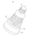
본 발명과 관련된 조명장치는 벌브(Bulb) 타입 조명장치(도 8 참조), PAR(Parabolic Aluminized Reflector Lamp) 타입 조명장치, 또는 평판형 조명장치(도 1 참조)일 수 있으며, 이하 설명의 편의를 위하여 평판형 조명장치를 예로 들어 설명한다.The lighting device related to the present invention can be a Bulb type lighting device (see FIG. 8), a PAR (Parabolic Aluminized Reflector Lamp) type lighting device, or a flat type lighting device (see FIG. 1) A planar lighting device will be described as an example.
상기 조명장치(100)는 외관을 형성하는 케이스(101)와 상기 케이스 내부에 마련되는 발광유닛(110) 및 상기 발광유닛(110)으로 전원을 공급하기 위한 전장부(180, 180-1, 180-2)를 포함한다.The
상기 케이스(101)는 전면(101a)과 후면(101b) 및 상기 전면(101a)과 후면(101b)을 연결하는 복수의 측면(101c)을 가질 수 있다. 이때 상기 전면(101a)에는 상기 발광유닛(110)으로부터 조사된 빛을 외부로 출사시키기 위한 광투과부가 마련된다.The
또한, 상기 전면(101a)과 후면(101b)은 수지 재질 또는 금속 재질로 형성될 수 있으며, 일 실시태양으로 상기 케이스(101)의 전면(101a)은 수지 재질로 형성되고, 상기 케이스(101)의 후면(101b)은 발광유닛(110)으로부터 발생하는 열을 효과적으로 발산시키기 위하여 금속 재질로 형성될 수 있다.The
상기 전면(101a)은 전면 패널로 구성될 수 있고, 상기 후면(101b)과 측면(101c)들은 후면 패널로 구성될 수 있다.The
여기서 상기 전면 패널은 상기 후면 패널에 탈착 가능하게 장착될 수 있으며, 일 실시태양으로 상기 전면 패널은 상기 후면 패널에 회전 가능하게 장착될 수 있다. 따라서, 상기 전면 패널을 개방시킨 상태에서 발광유닛(110) 및/또는 전장부(180)의 수리 및 교체가 가능하다.The front panel may be detachably mounted on the rear panel. In one embodiment, the front panel may be rotatably mounted on the rear panel. Therefore, the
상기 발광유닛(110)은 상기 케이스(101) 내부에 배치되는 기판(111)과 상기 기판(111)에 마련된 하나 이상의 LED(112)를 포함하며, 상기 케이스(101)의 전면 패널과 후면 패널 사이 공간에 배치되며, 열전달 특성을 높이기 위하여 상기 발광유닛(110)은 금속 재질의 후면 패널에 밀착하여 배치될 수도 있다.The
또한, 상기 조명장치(100)는 상기 발광유닛(110)으로부터 조사되는 빛을 확산시키기 위한 확산 부재(도시되지 않음)를 포함할 수도 있고, 상기 조명장치(100)는 상기 발광유닛(110)으로부터 조사되는 빛을 케이스(101)의 전면(101a)으로 반사시키기 위한 반사 부재(도시되지 않음)를 포함할 수도 있다.The
또한, 상기 조명장치(100)는 상기 발광유닛(110)으로부터 조사되는 빛의 경로를 조절하기 위한 집광렌즈 또는 마이크로 렌즈 어레이와 같은 하나 이상의 렌즈(도시되지 않음)를 포함할 수도 있다.In addition, the
상기 전장부(180)는 외부로부터 공급되는 교류전원(AC)을 직류전원(DC)으로 변환시키기 위한 AC-DC 컨버터를 포함할 수 있고, 상기 전장부(180)는 상기 AC-DC 컨버터와 연결되는 DC-DC 컨버터를 포함할 수 있다.The
또한, 상기 전장부(180)에는 상기 발광유닛(110)의 온(On)/오프(Off) 제어, 조도 제어(Dimming contol) 또는 색온도 제어 등을 위한 마이컴이 마련될 수 있다.The
도 1의 (a)를 참조하면, 상기 전장부(180)는 상기 케이스(101)의 내부에 위치될 수 있으며, 구체적으로 상기 전장부(180)는 상기 케이스(101a)의 전면(101a)에서 후면(101c) 방향을 따라 상기 발광유닛(120)과 중첩되도록 배치될 수 있다.1 (a), the
이와는 다르게, 도 1의 (b)를 참조하면, 전장부(180-1)는 상기 케이스(101)의 내부에 위치될 수 있으며, 상기 발광유닛(120)과 상기 전장부(180-1)는 나란히 배치될 수 있다.1 (b), the front unit 180-1 may be positioned inside the
이러한 구조에서 사용자가 전장부(180-1)를 교체하는 경우, 상기 케이스(101)의 전면 패널을 분리시키면 상기 발광유닛(110)과 상기 전장부(180)가 함께 외부로 노출될 수 있으며, 상기 전장부(180-1)와 상기 발광유닛(110)은 단일의 기판으로 구성될 수도 있다.In such a structure, when the front panel 180-1 is replaced by a user, the front panel of the
이와는 다르게, 도 1의 (c)를 참조하면, 전장부(180-2)는 상기 케이스(101) 외부에 위치될 수도 있으며, 예를 들어 상기 전장부(180-2)는 상기 케이스(101)의 101b) 또는 측면(101c)에 마련될 수도 있다.1 (c), the front portion 180-2 may be located outside the
이와 같이 전장부(180, 180-1, 180-2)는 조명장치(100)가 설치되는 환경 및 외관 디자인에 따라 다양한 위치에 마련될 수 있다.Thus, the
한편, 미설명부호 C는 상기 전장부(180, 180-1, 180-2)와 외부 전원장치(도시되지 않음)를 연결하는 케이블을 나타낸다.On the other hand, the unexplained reference character C denotes a cable connecting the
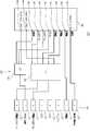
도 2는 본 발명의 일 실시예와 관련된 통신모듈(200)의 블록 구성도이고, 도 3은 본 발명의 일 실시예와 관련된 통신모듈(200)의 평면도이며, 도 4는 본 발명의 일 실시예와 관련된 통신모듈(200)의 사시도이다.FIG. 2 is a block diagram of a
또한, 도 5는 본 발명의 일 실시예와 관련된 통신모듈(200)의 접속상태를 설명하기 위한 개념도이다.5 is a conceptual diagram illustrating a connection state of the
상기 통신모듈(200)은 상기 조명장치(100)에 대한 제어신호가 수신되고, 상기 조명장치(100)의 작동상태를 송신하는 기능을 수행한다. 특히, 상기 통신모듈(200)은 장착과 수리 및 교체가 용이하도록 상기 조명장치(100)에 탈착 가능하게 장착된다.The
한편, 상기 통신모듈(200)은 상기 조명장치(100)를 제어하기 위한 단말기(300)와 무선 통신하기 위한 무선 통신부(230)를 포함한다.The
여기서 상기 무선 통신부(230)는 지그비(Zigbee), 와이파이(Wi-Fi), 블루투스(Bluetooth) 또는 Z-웨이브(Wave)을 통해 상기 단말기(300)와 무선 통신 가능하게 마련될 수 있다.The
한편, 상기 조명장치(100)를 제어하기 위한 단말기(300)는 휴대폰, 노트북, PDA(Personal Digital Assistance) 또는 컴퓨터일 수 있다.Meanwhile, the terminal 300 for controlling the
또한, 상기 단말기(300)는 조명장치(100)에 대한 제어명령을 입력받기 위한 입력부와 조명장치(100)의 상태정보를 표시하기 위한 출력부를 포함할 수 있으며, 상기 입력부와 출력부는 디스플레이부(310)로 구성될 수 있다.The terminal 300 may include an input unit for receiving a control command for the
상기 디스플레이부(310)는 사용자의 터치 입력이 가능하도록 구성될 수 있으며, 사용자는 디스플레이부(310) 상에 표시된 다양한 메뉴 항목을 선택함으로써 상기 조명장치(100)의 점등/소등, 조도 및/또는 색온도 등을 제어할 수 있다.The user may select various menu items displayed on the display unit 310 so that the
구체적으로, 상기 통신모듈(200)은 상기 조명장치(100)의 전장부(180)와 전기적으로 연결된다. 이때 상기 통신모듈(200)로는 상기 단말기(300)로부터 전송되는 조명장치(100)에 대한 제어신호가 수신되고, 상기 통신모듈(200)은 상기 조명장치(100)의 작동상태를 상기 단말기(300)로 송신한다.Specifically, the
따라서 사용자는 직접 조명장치(100)를 조작하지 않고도, 상기 단말기(300)를 통해 상기 조명장치(100)의 점등/소등, 조도 및/또는 색온도 등을 제어할 수 있으며, 상기 단말기(300)를 통해 상기 조명장치(100)의 작동상태를 모니터링할 수 있다.Therefore, the user can control the on / off, illuminance, and / or color temperature of the
또한, 상기 조명장치(100)의 상태 정보라 함은 조명장치(100)의 온/오프 상태 및 조명장치(100)의 온도 정보, 조명공간의 조도 정보, 조명장치(100)의 밝기 정보 및 색온도 정보와 같은 작동 정보를 포함할 수 있다.The state information of the
이하 첨부된 도면을 참조하여 통신모듈(200)을 구체적으로 설명한다.Hereinafter, the
도 2 및 도 3을 참조하면, 상기 통신모듈(200)은 회로기판(210)과 상기 회로기판(210)에 마련되며, 단말기(300)로부터 조명장치(100)에 대한 제어신호를 수신하고 상기 조명장치(100)의 작동상태를 단말기로 송신하기 위한 무선 통신부(230) 및 상기 무선 통신부(230)와 연결되며, 상기 조명장치(100)를 제어하기 위한 제어부(220)를 포함한다.2 and 3, the
여기서 상기 제어부(220)에는 상기 조명장치(100)의 PWM(Pulse Width Modulation) 제어를 위한 출력단과 상기 조명장치(100)와의 UART(Universal Asynchronous Receiver/Transmitter) 통신을 위한 입/출력단 및 ADC(Analog to Digital Converter) 입력단이 각각 마련된다.The
특히, 상기 ADC 입력단은 상기 조명장치(100)의 상태정보를 입력받기 위한 제1 ADC입력단(248)과 조명장치(100)의 전장부(180)로부터 모드 레벨을 입력받기 위한 제2 ADC 입력단(241)과 포함한다.Particularly, the ADC input terminal includes a first
상기와 같은 입력단과 출력단을 통하여 상기 통신모듈(200)과 상기 조명장치(100)의 전장부(180)가 전기적으로 연결되면, 상기 통신모듈(200)은 조명장치(100)의 PWM 제어를 위한 작동 모드, 조명장치(100)와의 UART 통신을 위한 작동 모드 및/또는 제1 ADC입력단(248)을 통한 ADC 입력을 위한 작동 모드로 작동될 수 있다.When the
상기 통신모듈(200)을 통한 상기 조명장치(100)의 PWM 제어를 살펴보면, 상기 PWM 출력단은 복수의 PWM 채널로 구성될 수 있으며, 해당 PWM 채널이 전장부(180)를 통해 LED(112)와 연결될 수 있다.The PWM output of the
일 실시태양으로, 상기 조명장치(100)는 레드(Red) LED, 그린(Green) LED, 블루(Blue) LED, 및 화이트(White) LED를 포함할 수 있다.In one embodiment, the
이때, 제어부(220)에는 전술한 바와 같이, 각 LED(112)들과 연결되는 복수의 PWM 채널이 마련되며, 상기 제어부(220)는 해당 PWM 채널의 PWM 값을 각각 조절함으로써 상기 조명장치(100)로부터 조사되는 빛의 색상이 조절할 수 있다.As described above, the
즉, 상기 전장부(180)를 통해 각 PWM 채널에 대하여 레드(Red) LED, 그린(Green) LED, 블루(Blue) LED, 및 화이트(White) LED가 각각 연결되고, 상기 제어부(220)는 PWM 4개 채널의 PWM 값을 각각 조절하여 원하는 색상을 표현할 수 있다.That is, a red LED, a green LED, a blue LED, and a white LED are connected to the respective PWM channels through the
마찬가지로, 상기 제어부(220)는 해당 PWM 채널의 PWM값을 각각 조절함으로써 상기 조명장치로부터 조사되는 빛의 색온도가 조절할 수 있다. 일 실시태양으로, PWM 4개 채널 또는 PWM 2개 채널을 이용하여 4가지 이하 색온도 또는 2가지 이하의 색온도 조절이 가능할 수 있다.Similarly, the
한편, 상기 통신모듈(200)과 상기 조명장치(100)의 UART 통신을 살펴보면, 상기 통신모듈(200)은 UART통신을 통해 조명장치(100)의 전장부(180)와 프로토콜(Protocol)에 맞는 패킷(Packet)을 주고 받을 수 있다.The UART communication between the
또한, UART 통신을 통해 온/오프, 밝기, 색온도와 같은 조명장치(100)의 상태정보에 대한 모니터링, 온/오프 제어, 디밍 제어, 컬러 제어 및 색온도 제어가 가능하다.Also, status information of the
전술한 바와 같이, 상기 통신모듈(200)은 조명장치(100)의 PWM 제어를 위한 작동 모드, 조명장치(100)와의 UART 통신을 위한 작동 모드 및/또는 제1 ADC입력단(248)을 통한 ADC 입력을 위한 작동 모드로 작동될 수 있다.As described above, the
구체적으로, 상기 조명장치(100)의 전장부(180)의 모드 레벨에 기초하여, 상기 통신모듈(200)은 PWM 제어와 UART 통신 및 ADC 입력 중 적어도 하나 이상을 포함하는 작동 모드로 작동될 수 있다.Specifically, based on the mode level of the
일 실시태양으로, 상기 통신모듈(200)은 PWM 제어를 위한 제1 작동 모드와 PWM 제어와 UART 통신 및 ADC입력을 위한 제2 작동 모드 및 PWM 제어와 ADC 입력을 위한 제3 작동 모드를 포함할 수 있다.In one embodiment, the
또한, 상기 제어부는 제1 내지 제3 작동 모드 중 어느 한 작동 모드를 선택하기 위한 복수의 스위치(261, 262)를 추가로 포함할 수 있다.In addition, the controller may further include a plurality of
일 실시태양으로, 상기 제1 작동 모드의 PWM 채널의 수는 제 2 및 제3 작동모드의 PWM 채널의 수보다 크게 결정되고, 제3 작동 모드의 PWM 채널의 수는 제2 작동 모드의 PWM 채널의 수보다 크게 결정될 수 있다. 이는 제2 작동모드에서 UART 통신을 위한 입/출력단이 사용되어야 하고, 제3 작동모드에서 ADC입력단이 사용되어야 하기 때문이다.In one embodiment, the number of PWM channels in the first operating mode is determined to be greater than the number of PWM channels in the second and third operating modes, and the number of PWM channels in the third operating mode is greater than the number of PWM channels in the second operating mode Can be determined to be larger than the number This is because the input / output stage for UART communication must be used in the second operation mode, and the ADC input stage must be used in the third operation mode.
특히, 제1 작동 모드의 경우, 전술한 바와 같이, 조명장치(100)가 레드(Red) LED, 그린(Green) LED, 블루(Blue) LED, 및 화이트(White) LED를 포함하고, 제어부(220)에 각 LED들과 연결되는 복수의 PWM 채널이 마련되면, 상기 제어부(220)는 상기 제1 작동 모드에서 해당 PWM 채널의 PWM값을 각각 조절함으로써 상기 조명장치로부터 조사되는 빛의 색상이 조절될 수 있다.In particular, in the first operating mode, as described above, the
마찬가지로, 상기 제어부(220)는 상기 제1 작동 모드에서 해당 PWM 채널의 PWM값을 각각 조절함으로써 상기 조명장치(100)로부터 조사되는 빛의 색온도가 조절될 수 있다.Likewise, the
한편 상기 전장부(180)의 모드 레벨(mode level)은 상기 통신모듈(200)의 제2 ADC 입력단(241)을 통해 입력되며, 상기 제어부(220)는 상기 전장부(180)의 모드 레벨에 기초하여 특정 작동 모드를 결정할 수 있다.Meanwhile, the mode level of the
즉, 상기 통신모듈(200)은 제2 ADC 입력값(241)에 따라 다양한 작동 모드를 입력받을 수 있으며, 상기 제어부(220)는 입력된 작동 모드에 해당하는 출력 인터페이스를 설정할 수 있다.That is, the
도 2 및 도 3을 참조하면, 상기 제어부(220)는 복수의 입력단 및 출력단을 각각 갖는 메인 칩셋(240)과 조명장치(100)의 전장부(180)와 접속되는 복수의 핀(251 내지 258)이 마련된 단자부(250) 및 상기 메인 칩셋(240)과 상기 단자부(250)를 연결하는 작동 모드 변경부(260)를 포함할 수 있다.2 and 3, the
또한, 상기 작동 모드 변경부(260)는 메인 칩셋(240)과 단자부(250)를 연결하는 복수의 스위치(261, 262)를 포함한다.The operation
여기서 상기 메인 칩셋(240)에는 제1 및 제2 ADC 입력단과 복수의 PWM 출력단과 UART입력단 및 UART 출력단이 각각 마련될 수 있다.The
상기 작동모드 변경부(260)는 메인 칩셋(240)의 복수의 PWM 출력단과 UART입/출력단 중 하나를 단자부(250)와 선택적으로 연결시키기 위한 제1 스위치(261)와 상기 메인 칩셋(240)의 PWM 출력단과 제1 ADC입력단(248) 중 하나를 단자부(250)와 선택적으로 연결시키기 위한 제2 스위치(262)를 포함할 수 있다.The operation
일 실시태양으로, 상기 메인 칩셋(240)에는 전장부(180)의 모드 레벨을 입력받기 위한 제2 ADC 입력단(ADC 1, 241)이 마련되고, PWM 출력을 위한 복수의 PWM 출력단(242 내지 245)이 마련될 수 있다.In one embodiment, the
특히 PWM 출력단은 복수의 PWM 채널을 구성할 수 있도록 복수로 구비되며, 일 실시태양으로 PWM출력단은 4개의 채널을 구성하도록 PWM0 내지 PWM4(242 내지 245)를 포함할 수 있다.In particular, a plurality of PWM output stages are provided so as to form a plurality of PWM channels, and in one embodiment, the PWM output stage may include PWM0 to PWM4 (242 to 245) to constitute four channels.
또한, 상기 메인 칩셋(240)에는 UART 통신을 위한 UART 입력단(UART_Rx, 246)과 UART 출력단(UART_Tx, 247) 및 제1 ADC 입력단(ADC 0, 248)이 마련될 수 있다.A UART
한편, 상기 단자부(250)는 조명장치(100)의 전장부(180)와 전기적으로 접속되는 복수의 핀이 마련되며, 일 실시태양으로, 8개의 핀이 마련될 수도 있다. 그러나 단자부(250)에 마련되는 핀의 개수는 통신모듈(200)의 출력 인터페이스의 개수에 대응될 수 있도록 다양하게 결정될 수 있음은 물론이다.The
구체적으로 상기 단자부(250)에는 전장부(180)의 모드 레벨을 입력받기 위한 제1 핀(Mode Select, 251)과 복수의 PWM출력을 위한 제2 핀(PWM0, 252)과 제6 핀(PWM1, 256)과 제7 핀(PWM3, 257) 및 제8 핀(PWM2, 257)이 각각 마련될 수 있다.More specifically, the
또한, 상기 단자부(250)에는 통신모듈(200)로 전원이 공급되는 제3 핀(253)과 접지를 위한 제4 핀(254) 및 제5 핀(255)이 각각 마련될 수 있다.The
특히, 제6 핀(256)은 선택적으로 PWM 출력(PWM1) 또는 UART 입력(UART_Rx)으로 사용될 수 있고, 제7 핀(257)은 선택적으로 PWM 출력(PWM3) 또는 ADC 입력으로 사용될 수 있으며, 제8 핀(258)은 선택적으로 PWM 출력(PWM2) 또는 UART 출력(UART_Tx)으로 사용될 수 있다.In particular, the
또한, 상기 제어부(220)는 상기 메인 칩셋(240)과 상기 단자부(250)를 연결하는 작동 모드 변경부(260)를 포함하며, 상기 작동 모드 변경부(260)는 메인 칩셋(240)과 단자부(250)를 연결하는 복수의 스위치(261, 262)를 포함한다.The
제1 스위치(261)는 PWM제어를 위한 PWM 1번 채널 및 PWM 2번 채널 또는 UART통신을 위한 UART_Rx 및 UART_Tx를 선택할 수 있으며, 제1 스위치(261)의 동작에 따라 상기 통신모듈(200)은 PWM 출력 또는 UART 통신 모드로 작동될 수 있다.The
제2 스위치(262)는 PWM 3번 채널 또는 ADC 입력을 선택할 수 있으며, 제2 스위치(262)의 동작에 따라 상기 통신모듈(200)은 PWM 출력 또는 ADC 입력 모드로 작동될 수 있다.The
한편, 상기 메인 칩셋(240)에는 제1 모드 출력단(Mode Select_Out 1, 249-1)과 제2 모드 출력단(Mode Select_Out 2, 249-2)이 마련될 수 있으며, 제1 모드 출력단(Mode Select_Out 1, 249-1)은 제1 스위치(261)와 연결되고, 제2 모드 출력단(Mode Select_Out 2, 249-2)은 제2 스위치(262)와 연결될 수 있다.The
상기 메인 칩셋(240)의 제1 ADC 입력단(241)은 상기 제1 핀(251)과 연결되고, 상기 메인 칩셋(240)의 PWM 출력단 중 1번과 2번 채널(PWM1, PWM2)은 제1 스위치(261)와 연결되며, 0번 채널은 직접 제2 핀(252)과 연결되고, 3번 채널(PWM3)은 제2 스위치(262)와 연결될 수 있다.The first
또한, 상기 단자부(250)의 제6 핀(256)과 제8 핀(258)은 제1 스위치(261)와 연결되고, 상기 제7 핀(257)은 제2 스위치(262)와 연결될 수 있다.The
이와 같은 구조에서, 상기 통신모듈(200)은 상기 조명장치(100)의 전장부(180)의 모드 레벨(예를 들어, 0, 0.5, 및 1)에 기초하여, PWM 제어와 UART 통신 및 ADC 입력 중 적어도 하나 이상을 포함하는 작동 모드로 작동될 수 있다.In this configuration, the
구체적으로, 상기 메인 칩셋(240)의 제1 및 제2 ADC 입력단(248, 241)은 아날로그 입력을 받아서 내부적으로 디지털 신호로 변경할 수 있는 기능을 가진 포트로서, 디지털 변환 범위가 8비트(bit)이면 256 레벨로 범위를 넓힐 수 있고, 16비트(bit)이면 65,536 레벨로 범위를 넓힐 수 있다.Specifically, the first and second
따라서 조명장치(100)의 전장부(180)에서 모드 레벨이 결정되며, 결정된 모드 레벨은 제1 핀(251)을 통하여 상기 메인 칩셋(240)의 제2 ADC 입력단(241)으로 입력되고, 상기 제어부(240)는 입력된 모드 레벨에 맞추어 상기 통신모듈(200)의 작동 모드를 결정하게 된다.The mode level is determined at the
도 2를 참조하면, 상기 작동 모드는 PWM 제어를 위한 제1 작동 모드와 PWM 제어와 UART 통신 및 ADC입력을 위한 제2 작동 모드 및 PWM 제어와 ADC 입력을 위한 제3 작동 모드를 포함할 수 있다.Referring to Figure 2, the operating mode may include a first operating mode for PWM control, a second operating mode for PWM control and UART communication and ADC input, and a third operating mode for PWM control and ADC input .
일 실시태양으로, 제1 작동 모드의 경우, 전장부(180)로부터 입력되는 모드 레벨이 1일 수 있으며, 메인 칩셋(240)의 제1 및 제2 모드 출력단(249-1, 249-2)이 작동하여 제1 스위치(261)와 제2 스위치(262)의 동작에 따라 PWM 4개 채널이 출력될 수 있다.In one embodiment, in the first mode of operation, the mode level input from the
이와는 다르게, 제2 작동 모드의 경우, 전장부(180)로부터 입력되는 모드 레벨이 0일 수 있으며, 메인 칩셋(240)의 제1 스위치(261)와 제2 스위치(262)의 동작에 따라 1개 채널의 PWM 출력과 UART 통신 및 제1 ADC입력단(248)을 통한 ADC 입력이 가능해진다.Alternatively, in the second operation mode, the mode level input from the
이와는 다르게, 제3 작동 모드의 경우, 전장부(180)로부터 입력되는 모드 레벨이 0.5일 수 있으며, 메인 칩셋(240)의 제1 스위치(261)와 제2 스위치(262)의 동작에 따라 3개 채널의 PWM 출력과 제1 ADC입력단(248)을 통한 ADC 입력이 가능해진다.Alternatively, in the third mode of operation, the mode level input from the
또한, 제3 작동 모드는 PWM 채널을 많이 사용하면서 ADC 입력을 통한 제어 시나리오를 구현하고자 할 때 설정 가능하며, PWM 3개 채널을 통해 색상 제어 또는 색온도 제어를 할 수 있고, ADC 입력을 통한 제어가 가능해진다.In addition, the third operation mode can be set up to implement a control scenario through the ADC input while using a lot of PWM channels. Color control or color temperature control can be performed through three PWM channels and control through ADC input It becomes possible.
따라서, 상기 제1 작동 모드의 PWM 채널의 수는 제 2 및 제3 작동모드의 PWM 채널의 수보다 크게 결정되고, 제3 작동 모드의 PWM 채널의 수는 제2 작동 모드의 PWM 채널의 수보다 크게 결정될 수 있다.Therefore, the number of PWM channels in the first operation mode is determined to be larger than the number of PWM channels in the second and third operation modes, and the number of PWM channels in the third operation mode is larger than the number of PWM channels in the second operation mode Can be largely determined.
이와 같이 작동모드 변경부(260)를 통해 상기 통신모듈(200)은 특정 작동 모드로 동작할 수 있게 된다.In this manner, the
한편, 조명장치(100)의 스펙에 따라 상기 전장부(180)의 모드 레벨은 하나로 결정될 수 있다. 구체적으로, 전장부(180)는 PWM 제어만 지원할 수도 있고, UART통신만을 지원할 수도 있으며, 그 결과 전장부(180)의 특성에 맞추어 별도의 통신모듈이 제작되어야 한다.On the other hand, according to the specifications of the
그러나 본 발명의 일 실시예와 관련된 통신모듈(200)은 전장부(180)의 모드 레벨에 기초하여 특정 작동 모드로 동작될 수 있으므로, 다양한 스펙의 조명장치(100)에 범용 가능한 효과를 갖는다.However, since the
정리하면, 상기 통신모듈(200)은 전장부(180)로부터 제2 ADC입력단(241)을 통해 입력되는 ADC 입력 값에 따라 다양한 작동 모드를 입력받을 수 있으며, 이에 해당하는 다양한 출력 인터페이스를 설정할 수 있다.In summary, the
한편, 도 3 및 4를 참조하면, 상기 통신모듈(200)은 외관을 형성하도록 상기 회로기판(210)을 둘러싸는 하우징(201)을 포함할 수 있다. 상기 하우징(201)은 상기 조명장치(100)에 탈착 가능하게 장착될 수 있다.3 and 4, the
여기서 상기 메인 칩셋(240)은 하우징(201) 내부에 마련되고, 상기 단자부(250)는 하우징(201) 외부로 노출된다. 또한, 상기 하우징(201)은 무선 통신부(230)가 수용되는 제1 영역(202)과 메인 칩셋(240)이 수용되는 제2 영역(203)으로 구분될 수 있다.The
또한, 간섭을 방지하기 위하여 무선 통신부(230)는 조명장치(100)로부터 최대한 멀어지는 것이 바람직하며, 이에 따라 상기 메인 칩셋(240)은 상기 단자부(250)와 상기 무선 통신부(230) 사이에 위치된다.In order to prevent interference, the
또한, 상기 하우징(201)이 조명장치(100)에 장착되는 경우, 상기 하우징(201)의 제1 영역(202)은 조명장치(100)의 외부로 노출되는 것이 바람직하다.When the
또한, 제1 영역(202)의 폭(d1)은 제2 영역(203)의 폭(d2)보다 넓게 결정되는 것이 바람직하다. 상기 하우징(201)은 폭 차이에 의한 단차 구조가 가짐으로써 용이하게 조명장치(100)에 탈착 가능하게 장착될 수 있다.It is preferable that the width d1 of the
도 5를 참조하면, 상기 전장부(180)는 상기 조명장치(100)의 케이스(101) 내부에 위치될 수 있으며, 상기 전장부(180)에는 상기 통신모듈(200)과 접속되기 위한 커넥터(181)가 마련된다.5, the
또한, 상기 커넥터(181)는 상기 통신모듈(200)의 단자부(250)와 전기적으로 접속되며, 상기 커넥터(181)는 상기 전장부(180)의 회로기판(S)에 마련될 수 있다.The
한편, 상기 전장부(180)가 상기 케이스(101) 내부에 위치되는 경우(도 1 참조), 상기 통신모듈(200)은 상기 조명장치(100)의 케이스(101)를 관통하여 상기 전장부(180)의 커넥터(181)와 연결될 수 있다. 상기 통신모듈(200)이 삽입될 수 있도록 상기 케이스(101)에는 개구부가 마련될 수 있다.1), the
도 6은 본 발명의 일 실시예와 관련된 통신모듈과 전장부를 나타내는 개념도이다.6 is a conceptual diagram showing a communication module and an electric field part according to an embodiment of the present invention.
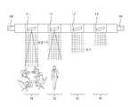
또한, 도 7은 본 발명의 일 실시예와 관련된 조명장치의 일 작동상태를 설명하기 위한 개념도이고, 도 8은 본 발명의 일 실시예와 관련된 조명장치의 또 다른 작동상태를 설명하기 위한 개념도이다.7 is a conceptual view for explaining an operation state of a lighting apparatus according to an embodiment of the present invention, and Fig. 8 is a conceptual diagram for explaining another operation state of a lighting apparatus according to an embodiment of the present invention .
상기 전장부(180)는 AC-DC 컨버터(183)와 DC-DC 컨버터(184)를 포함할 수 있고, 상기 전장부(180)는 LED(112)를 구동하기 위한 마이컴(182)을 포함할 수 있다.The
상기 통신모듈(200)의 제어부(220)는 제1 ADC입력단(248)을 통해 조명장치(100)의 온도 정보, 조명 공간의 조도 정보 및 조명 공간의 재실자 정보 중 적어도 하나 이상의 상태 정보 감지가 가능하다.The
또한, 제1 ADC 입력단(248)은 조명장치 또는 조명공간에 대한 상태정보를 아날로그 입력을 받은 후 내부적으로 디지털 신호로 변경할 수 있는 기능을 가진 포트로서, 디지털 변환 범위가 8비트(bit)이면 256 레벨로 범위를 넓힐 수 있고, 16비트(bit)이면 65,536 레벨로 범위를 넓힐 수 있으므로, 정밀한 모니터링 및 제어가 가능해진다.In addition, the first
한편, 제2 ADC 입력단(241)은 작동모드 변경부와 관계없이 제1 핀(251)과 연결되고, 제1 ADC입력단(248)의 경우 특정 작동모드(제3 작동모드)에서만 그 기능이 이루어질 수도 있다.On the other hand, the second
또한, 상기 조명장치(100)는 조명장치 내부 온도를 감지하기 위한 온도 센서(185)를 추가로 포함하며, 상기 온도 센서(185)는 제1 ADC 입력단(248)과 전기적으로 연결된다.The
따라서, 제1 ADC입력단(248)으로 입력되는 ADC 입력 값에 온도 센서(185)를 연결하여 조명 장치(100)의 온도를 감지하여, 디밍 제어를 통해 조명 장치(100)의 온도를 적정수준으로 유지할 수 있다.Therefore, the
구체적으로, 제어부(220)는 조명장치(100)의 온도가 기준 온도보다 높은 경우 PWM 제어를 통해 발광유닛(110)의 디밍값을 감소시키고, 조명장치의 온도가 기준 온도보다 낮은 경우 PWM 제어를 통해 발광유닛(100)의 디밍값을 증가시킬 수 있다.Specifically, when the temperature of the
즉, 조명장치(100)의 온도가 올라가면 디밍 값을 낮춰 밝기를 낮춤으로써 조명장치(100)의 온도를 낮게 만들고, 조명장치(100)의 온도가 내려가면 디밍 값을 높여 밝기를 증가시킴으로써 조명장치(100)의 온도를 증가시킬 수 있다.That is, when the temperature of the
또한, 상기 온도센서(185)는 전장부(180) 내부에 마련될 수 있다.In addition, the
도 7을 참조하면, 상기 조명장치(100)는 조명 공간(S1 내지 S4)의 조도를 감지하기 위한 조도 센서(187)를 추가로 포함할 수 있으며, 상기 조도 센서(187)는 제1 ADC 입력단(248)과 전기적으로 연결될 수 있다.7, the
즉, 제1 ADC입력단(248)으로 입력되는 ADC 입력 값에 조도 센서(187)를 연결하여 조명 장치(100)의 주변 조도 값에 따라 디밍 제어를 통해 조명 장치의 밝기를 조절할 수 있다.That is, the
구체적으로, 제어부(220)는 감지된 조도값에 기초하여 PWM 제어를 통해 발광유닛(110)의 디밍값을 제어할 수 있다.Specifically, the
도 7을 참조하면, M은 측정된 조도값을 나타내고, 도면부호 L1은 제1 조명공간(S1)에 대응되는 제1 조명장치를 나타내고, 도면부호 L2는 제2 조명공간(S2)에 대응되는 제2 조명장치를 나타내며, 도면부호 L3는 제3 조명공간(S3)에 대응되는 제3 조명장치를 나타내고. 도면부호 L4는 제4 조명공간(S4)에 대응되는 제4 조명장치를 나타낸다.Referring to FIG. 7, M represents a measured illuminance value, reference numeral L1 represents a first illuminating device corresponding to the first illuminating space S1, and reference numeral L2 represents a second illuminating space corresponding to the second illuminating space S2 And L3 denotes a third illuminating device corresponding to the third illuminating space S3. Reference numeral L4 denotes a fourth illumination device corresponding to the fourth illumination space S4.
이와 같이, 조도값이 높게 측정된 제1 조명장치(L1)의 경우, 디밍값을 감소킴으로써 전력 사용량을 줄일 수 있고, 조도값이 낮제 측정된 제4 조명장치(L4)의 경우, 디밍값을 증가시킴으로써 쾌적한 조명환경을 제공할 수 있다.As described above, in the case of the first illuminating device L1 having a high illuminance value, the power consumption can be reduced by reducing the dimming value. In the case of the fourth illuminating device L4 whose illumination value is measured low, It is possible to provide a pleasant lighting environment.
도 8을 참조하면, 상기 조명장치(100)는 조명공간의 재실자 정보를 감지하기 위한 동체 감지 센서(188)를 추가로 포함할 수 있고, 상기 동체 감지 센서(188)는 제1 ADC 입력단(248)과 전기적으로 연결될 수 있다.8, the
또한, 제1 ADC입력단(248)으로 입력되는 ADC 입력 값에 동체 감지 센서를 연결함으로써, 제어부(202)는 감지된 재실자 정보에 기초하여 PWM 제어를 통해 발광유닛(100)의 온/오프 및 디밍값 중 적어도 하나 이상을 제어할 수 있다.Also, by connecting the moving body detection sensor to the ADC input value input to the first
도 8을 참조하면, 도면부호 L1은 제1 조명공간(S1)에 대응되는 제1 조명장치를 나타내고, 도면부호 L2는 제2 조명공간(S2)에 대응되는 제2 조명장치를 나타내며, 도면부호 L3는 제3 조명공간(S3)에 대응되는 제3 조명장치를 나타내고. 도면부호 L4는 제4 조명공간(S4)에 대응되는 제4 조명장치를 나타낸다.Referring to Fig. 8, reference numeral L1 denotes a first illumination device corresponding to the first illumination space S1, reference symbol L2 denotes a second illumination device corresponding to the second illumination space S2, And L3 denotes a third illumination device corresponding to the third illumination space S3. Reference numeral L4 denotes a fourth illumination device corresponding to the fourth illumination space S4.
이와 같이 재실자가 감지되지 않는 제4 조명공간(S4)에서는 제4 조명장치(L4)를 오프(off)시키고, 재실자가 감지된 제2 조명공간(S2)에서는 제2 조명장치(L4)를 온(On)시키며, 재실자가 많이 감지된 제1 조명공간(S1)에서는 제1 조명장치(L1)의 밝기를 증가시킬 수 있다.The fourth illumination device L4 is turned off in the fourth illumination space S4 in which the occupant is not sensed and the second illumination device L4 is turned on in the second illumination space S2 in which the occupant is sensed And the brightness of the first illuminating device L1 can be increased in the first illuminating space S1 in which a lot of occupants are detected.
한편, 상기 통신모듈(200)에는 스케줄 정보를 저장하기 위한 메모리부가 마련될 수 있고, 상기 제어부(220)는 저장된 스케줄 정보에 기초하여 PWM 제어를 통해 발광유닛(110)의 온/오프 및 디밍값 중 적어도 하나 이상을 제어할 수 있다.On the other hand, the
또한, 상기 스케줄 정보는 단말기(300)를 통해 상기 통신모듈(200)로 전달될 수 있다.Also, the schedule information may be transmitted to the
상기와 같은 스케줄 정보를 통해, 필요시에만 조명장치(100)가 작동되도록 하거나, 디밍값을 미리 설정함으로써 전력 사용량을 줄일 수 있고, 취침 시 디밍 값을 서서히 줄여 편안한 취침이 가능하도록 하거나, 기상 시 디밍 값을 서서히 높여 편안한 기상이 가능하도록 할 수 있다.Through the above-described schedule information, it is possible to reduce the power consumption by allowing the
도 9는 본 발명의 또 다른 실시예와 관련된 통신 모듈의 블록 구성도이다.9 is a block diagram of a communication module according to another embodiment of the present invention.
도 9는 저항 연결 방식을 통하여 특정 작동 모드로 결정되는 통신 모듈(200)을 나타내며, 작동 모드 변경부(270)에서 도 2를 통해 설명한 통신 모듈(200)과 차이를 갖는다.FIG. 9 shows a
또한, 도 2를 통하여 설명한 단자부(250)와 메인 칩셋(240)의 구조는 동일하며, 다만 저항 연결 방식의 경우 메인 칩셋(240)의 제1 및 제2 모드 출력단(249-1, 249-2)은 사용되지 않는다.2, the terminal 250 and the
도 9을 참조하면, 제1 저항(271)은 0번 채널 PWM 출력단(242)과 제6 핀(256)을 연결할 수 있고, 제2 저항(271)은 UART 입력단(246)과 제6 핀(256)을 연결할 수 있다.9, the
또한, 제3 저항(273)은 3번 채널 PWM 출력단(245)과 제7 핀(257)을 연결할 수 있고, 제4 저항(274)은 제1 ADC 입력단(248)과 제 7핀(257)을 연결할 수 있다.The third resistor 273 may connect the third
또한, 제5 저항(275)은 2번 채널 PWM 출력단(242)과 제8 핀(258)을 연결할 수 있고, 제6 저항(276)은 UART 출력단(247)과 제8 핀(258)을 연결할 수 있다.The
저항 연결 방식에서, 전술한 제1 작동 모드는 제1 저항(271)과 제3 저항(273) 및 제5 저항(275)의 각 저항값이 0Ω이고, 나머지 저항들은 연결되지 않음으로써 결정될 수 있다.In the resistance connection mode, the above-described first operation mode can be determined by the resistance value of each of the
마찬가지로, 제2 작동 모드는 제2 저항(272)과 제4 저항(274) 및 제6 저항(276)의 각 저항값이 0Ω이고, 나머지 저항들은 연결되지 않음으로써 결정될 수 있다.Likewise, the second operating mode can be determined by the resistance value of each of the
마찬가지로, 제3 작동 모드는 제1 저항(271)과 제4 저항(274) 및 제5 저항(275)의 각 저항값이 0Ω이고, 나머지 저항들은 연결되지 않음으로써 결정될 수 있다.Likewise, the third operating mode can be determined by the resistance values of the
도 10은 본 발명의 일 실시예와 관련된 통신모듈(200)의 일 장착상태를 설명하기 위한 사시도이다.10 is a perspective view for explaining a mounting state of the
도 10을 참조하면, 조명장치(400)는 벌브 타입 또는 PAR 타입 조명장치일 수 있다.Referring to FIG. 10, the
상기 조명장치(400)는 히트싱크(410)와 상기 히트싱크(410)에 마련되는 기판 및 상기 기판에 실장되는 LED를 포함하는 발광유닛(도 1참조)과 상기 발광유닛으로 전원을 공급하기 위하여 상기 히트싱크(410) 내부에 마련되는 전장부(도 1참조) 및 상기 히트싱크(410)를 통하여 상기 전장부에 탈착 가능하게 장착되는 통신모듈(200)을 포함한다.The
또한, 상기 조명장치(400)는 상기 발광유닛을 둘러싸도록 상기 히트싱크(410)에 장착되는 광학 부재(420)와 상기 전장부와 연결되며, 외부 전원을 공급받는 베이스(430)를 포함한다.The
여기서 상기 광학 부재(420)는 벌브 또는 렌즈일 수 있다.Here, the
이와 같은 구조에서 상기 통신모듈(200)은 상기 히트싱크(410)의 일부영역을 관통하여 내부에 위치된 전장부와 연결될 수 있다.In such a structure, the
또한, 도 4 및 도 10을 참조하면, 상기 통신모듈(200)의 하우징(201)의 제1 영역(202)은 히트싱크(410) 외부로 노출되는 것이 바람직하다.4 and 10, it is preferable that the
이상에서 살펴본 바와 같이, 본 발명의 일 실시예와 관련된 조명장치에 따르면, 무선으로 개별/그룹 제어가 용이한 조명 제어 시스템을 구현할 수 있다.As described above, according to the lighting apparatus related to one embodiment of the present invention, it is possible to implement a lighting control system that can easily control individual / group by wireless.
또한, 본 발명의 일 실시예와 관련된 조명장치에 따르면, 다양한 출력 인터페이스 및 제어 인터페이스가 구현된다.Further, according to the lighting apparatus according to one embodiment of the present invention, various output interfaces and control interfaces are implemented.
또한, 본 발명의 일 실시예와 관련된 조명장치에 따르면, 온도 정보, 조도 정보 및 재실자 정보와 같은 상태 정보에 기초한 제어가 가능하다.Further, according to the illumination device related to one embodiment of the present invention, control based on state information such as temperature information, illumination information and occupant information is possible.
또한, 본 발명의 일 실시예와 관련된 조명장치에 따르면, PWM출력, UART 입/출력 및 ADC 입력을 통해 다양한 인터페이스가 구현된다.Further, according to the lighting device related to one embodiment of the present invention, various interfaces are implemented through PWM output, UART input / output, and ADC input.
또한, 본 발명의 일 실시예와 관련된 조명장치에 따르면, 무선으로 점등(on)/소등(off), 조도(dimming) 또는 색온도를 제어할 수 있다.In addition, according to the illumination device related to one embodiment of the present invention, it is possible to control on / off, dimming, or color temperature by wirelessly.
또한, 본 발명의 일 실시예와 관련된 조명장치에 따르면, 통신모듈이 조명장치에 탈착 가능하게 장착될 수 있다.Further, according to the illumination device related to the embodiment of the present invention, the communication module can be detachably mounted to the illumination device.
또한, 본 발명의 일 실시예와 관련된 조명장치에 따르면, 조립 및 설치가 간편하고, 수리 및 교체가 용이하다.Further, according to the lighting apparatus relating to one embodiment of the present invention, assembly and installation are simple, and repair and replacement are easy.
위에서 설명된 본 발명의 바람직한 실시예는 예시의 목적을 위해 개시된 것이고, 본 발명에 대한 통상의 지식을 가지는 당업자라면 본 발명의 사상과 범위 안에서 다양한 수정, 변경, 부가가 가능할 것이며, 이러한 수정, 변경 및 부가는 하기의 특허청구범위에 속하는 것으로 보아야 할 것이다.The foregoing description of the preferred embodiments of the present invention has been presented for purposes of illustration and various modifications, additions and substitutions are possible, without departing from the scope and spirit of the invention, And additions should be considered as falling within the scope of the following claims.
100: 조명장치101: 케이스
110: 발광유닛180: 전장부
200: 통신모듈201: 하우징
220: 제어부230: 무선 통신부
240: 메인 칩셋250: 단자부
260, 270: 작동모드 변경부
300: 단말기310: 디스플레이부
400: 조명장치100: illumination device 101: case
110: Light emitting unit 180:
200: communication module 201: housing
220: control unit 230: wireless communication unit
240: main chipset 250: terminal portion
260, 270: Operation mode changing section
300: Terminal 310:
400: Lighting device
Claims (17)
Translated fromKorean상기 케이스 내부에 마련되는 기판 및 상기 기판에 실장된 LED를 포함하는 발광유닛;
상기 발광유닛으로 전원을 공급하기 위한 전장부;
상기 발광유닛 및 조명공간 중 적어도 하나의 상태 정보를 감지하기 위한 하나 이상의 센서; 및
상기 전장부에 탈착 가능하게 접속되는 통신모듈을 포함하며,
상기 통신모듈은, 단말기로부터 상기 발광유닛에 대한 제어신호를 수신하고 상기 발광유닛의 작동상태를 단말기로 송신하기 위한 무선 통신부 및 상기 무선 통신부와 연결되며 상기 발광유닛을 제어하기 위한 제어부를 포함하고,
상기 제어부에는 상기 발광유닛의 PWM(Pulse Width Modulation) 제어를 위한 출력단과 상기 센서로부터 감지된 상태 정보가 입력되는 제1 ADC(Analog to Digital Converter) 입력단이 각각 마련된 조명장치.case;
A light emitting unit including a substrate provided inside the case and an LED mounted on the substrate;
A power source for supplying power to the light emitting unit;
At least one sensor for sensing status information of at least one of the light emitting unit and the illumination space; And
And a communication module detachably connected to the front portion,
The communication module includes a wireless communication unit for receiving a control signal for the light emitting unit from the terminal and transmitting the operation state of the light emitting unit to the terminal, and a control unit connected to the wireless communication unit and controlling the light emitting unit,
Wherein the control unit is provided with an output terminal for PWM (Pulse Width Modulation) control of the light emitting unit and a first ADC (Analog to Digital Converter) input terminal for receiving the state information sensed by the sensor.
상기 조명장치의 온도를 감지하기 위한 온도 센서를 추가로 포함하며,
상기 온도 센서는 제1 ADC 입력단과 전기적으로 연결되는 것을 특징으로 하는 조명장치.The method according to claim 1,
Further comprising a temperature sensor for sensing the temperature of the illumination device,
And the temperature sensor is electrically connected to the first ADC input terminal.
상기 온도센서는 전장부 내부에 마련되는 것을 특징으로 하는 조명장치.3. The method of claim 2,
Wherein the temperature sensor is provided inside the front part.
제어부는 조명장치의 온도가 기준 온도보다 높은 경우 PWM 제어를 통해 발광유닛의 디밍값을 감소시키고, 조명장치의 온도가 기준 온도보다 낮은 경우 PWM 제어를 통해 발광유닛의 디밍값을 증가시키는 것을 특징으로 하는 조명장치.The method of claim 3,
The control unit decreases the dimming value of the light emitting unit through the PWM control when the temperature of the lighting apparatus is higher than the reference temperature and increases the dimming value of the light emitting unit through the PWM control when the temperature of the lighting apparatus is lower than the reference temperature Lt; / RTI >
조명 공간의 조도를 감지하기 위한 조도 센서를 추가로 포함하며,
상기 조도 센서는 제1 ADC 입력단과 전기적으로 연결되는 것을 특징으로 하는 조명장치.The method according to claim 1,
Further comprising an illuminance sensor for sensing illuminance of the illumination space,
And the illuminance sensor is electrically connected to the first ADC input terminal.
제어부는 감지된 조도값에 기초하여 PWM 제어를 통해 발광유닛의 디밍값을 제어하는 것을 특징으로 하는 조명장치.6. The method of claim 5,
And the control unit controls the dimming value of the light emitting unit through the PWM control based on the sensed illumination value.
조명공간의 재실자 정보를 감지하기 위한 동체 감지 센서를 추가로 포함하며,
상기 동체 감지 센서는 제1 ADC 입력단과 전기적으로 연결되는 것을 특징으로 하는 조명장치.The method according to claim 1,
Further comprising a moving body detection sensor for detecting occupancy information of the illumination space,
Wherein the moving body detection sensor is electrically connected to the first ADC input terminal.
제어부는 감지된 재실자 정보에 기초하여 PWM 제어를 통해 발광유닛의 온/오프 및 디밍값 중 적어도 하나 이상을 제어하는 것을 특징으로 하는 조명장치.8. The method of claim 7,
Wherein the control unit controls at least one of on / off and dimming values of the light emitting unit through PWM control based on the sensed occupant information.
상기 통신모듈에는 스케줄 정보를 저장하기 위한 메모리부가 마련되며,
상기 제어부는 저장된 스케줄 정보에 기초하여 PWM 제어를 통해 발광유닛의 온/오프 및 디밍값 중 적어도 하나 이상을 제어하는 것을 특징으로 하는 조명장치.The method according to claim 1,
Wherein the communication module is provided with a memory for storing schedule information,
Wherein the control unit controls at least one of on / off and dimming values of the light emitting unit through PWM control based on the stored schedule information.
상기 스케줄 정보는 단말기를 통해 상기 통신모듈로 전달되는 것을 특징으로 하는 조명장치.10. The method of claim 9,
Wherein the schedule information is transmitted to the communication module through the terminal.
제어부에는 전장부의 모드 레벨을 입력받기 위한 제2 ADC입력단 및 전장부와 UART 통신을 위한 입/출력단이 각각 마련되며,
통신모듈은 상기 전장부의 모드 레벨에 기초하여, PWM제어와 UART통신 및 제1 ADC입력단을 통한 ADC입력 중 적어도 하나 이상을 포함하는 작동 모드로 작동되는 것을 특징으로 하는 조명장치.3. The method of claim 2,
The control unit is provided with a second ADC input terminal for receiving the mode level of the electric field unit, and an input / output terminal for the UART communication with the former unit,
Wherein the communication module is operated in an operating mode that includes at least one of PWM control, UART communication, and an ADC input through a first ADC input, based on the mode level of the electric field.
상기 제어부는 상기 전장부의 모드 레벨에 기초하여 특정 작동 모드를 결정하는 것을 특징으로 하는 조명장치.12. The method of claim 11,
Wherein the control unit determines a specific operation mode based on the mode level of the electric field portion.
PWM 제어를 위한 제1 작동 모드;
PWM 제어와 UART 통신 및 ADC 입력을 위한 제2 작동 모드;
PWM 제어와 ADC 입력을 위한 제3 작동 모드를 포함하는 조명장치.12. The method of claim 11,
A first operating mode for PWM control;
A second operating mode for PWM control and UART communication and ADC input;
And a third operating mode for PWM control and ADC input.
제어부에는 제1 내지 제3 작동 모드 중 어느 한 작동 모드를 선택하기 위한 복수의 스위치가 마련된 것을 특징으로 하는 조명장치.14. The method of claim 13,
Wherein the control unit is provided with a plurality of switches for selecting one of the first to third operation modes.
복수의 입력단 및 출력단을 각각 갖는 메인 칩셋;
전장부와 접속되는 복수의 핀이 마련된 단자부; 및
상기 메인 칩셋과 상기 단자부를 연결하는 작동 모드 변경부를 포함하는 조명장치.12. The apparatus according to claim 11,
A main chipset having a plurality of input terminals and an output terminal, respectively;
A terminal portion provided with a plurality of fins connected to the front portion; And
And an operation mode changing unit for connecting the main chip set and the terminal unit.
상기 메인 칩셋에는 제1 및 제2 ADC 입력단과 복수의 PWM 출력단과 UART입력단 및 UART 출력단이 각각 마련되고,
상기 작동 모드 변경부는 복수의 PWM 출력단과 UART입/출력단 중 하나를 단자부와 선택적으로 연결시키기 위한 제1 스위치와 PWM 출력단과 제1 ADC입력단 중 하나를 단자부와 선택적으로 연결시키기 위한 제2 스위치를 포함하는 조명장치.16. The method of claim 15,
The main chipset includes first and second ADC input terminals, a plurality of PWM output terminals, a UART input terminal and a UART output terminal,
The operation mode changing unit includes a first switch for selectively connecting one of a plurality of PWM output terminals and a UART input / output terminal to the terminal unit, and a second switch for selectively connecting the PWM output terminal and one of the first ADC input terminals to the terminal unit Lt; / RTI >
통신모듈의 외관을 형성하는 하우징을 추가로 포함하며,
상기 메인 칩셋은 하우징 내부에 마련되고, 상기 단자부는 하우징 외부로 노출되는 조명장치.16. The method of claim 15,
Further comprising a housing defining an exterior of the communication module,
Wherein the main chipset is provided inside the housing, and the terminal portion is exposed to the outside of the housing.
Priority Applications (1)
| Application Number | Priority Date | Filing Date | Title |
|---|---|---|---|
| KR20130042138AKR20140124529A (en) | 2013-04-17 | 2013-04-17 | Lighting apparatus |
Applications Claiming Priority (1)
| Application Number | Priority Date | Filing Date | Title |
|---|---|---|---|
| KR20130042138AKR20140124529A (en) | 2013-04-17 | 2013-04-17 | Lighting apparatus |
Publications (1)
| Publication Number | Publication Date |
|---|---|
| KR20140124529Atrue KR20140124529A (en) | 2014-10-27 |
Family
ID=51994732
Family Applications (1)
| Application Number | Title | Priority Date | Filing Date |
|---|---|---|---|
| KR20130042138ACeasedKR20140124529A (en) | 2013-04-17 | 2013-04-17 | Lighting apparatus |
Country Status (1)
| Country | Link |
|---|---|
| KR (1) | KR20140124529A (en) |
Cited By (1)
| Publication number | Priority date | Publication date | Assignee | Title |
|---|---|---|---|---|
| KR20190029240A (en)* | 2017-09-12 | 2019-03-20 | 주식회사 질라이트 | Dimming unit and communication unit for operating illuminator |
- 2013
- 2013-04-17KRKR20130042138Apatent/KR20140124529A/ennot_activeCeased
Cited By (1)
| Publication number | Priority date | Publication date | Assignee | Title |
|---|---|---|---|---|
| KR20190029240A (en)* | 2017-09-12 | 2019-03-20 | 주식회사 질라이트 | Dimming unit and communication unit for operating illuminator |
Similar Documents
| Publication | Publication Date | Title |
|---|---|---|
| EP3281495B1 (en) | Daylighting for different groups of lighting fixtures | |
| US9681516B2 (en) | Light emitting diode luminaire device and system with color temperature tunning | |
| US9723680B2 (en) | Digitally controlled driver for lighting fixture | |
| US9549448B2 (en) | Wall controller controlling CCT | |
| EP2935989B1 (en) | Auto commissioning lighting fixture | |
| CN109618445B (en) | Method and apparatus for an adaptable lighting unit to receive driving data from an external source | |
| US9807845B2 (en) | Light emitting diode luminaire device and system with color temperature tunning | |
| JP6444991B2 (en) | Integrated micro light-emitting diode module with built-in programmability | |
| EP3639624A1 (en) | Intelligent lighting module for a lighting fixture | |
| US11800618B2 (en) | Lighting device and lighting system comprising the lighting device | |
| TWI760292B (en) | A lighting device a lighting assembly and a regulating element | |
| US12267934B2 (en) | Driver electronics for light emitting diode light engine with integrated near field communication based controls including human centric lighting settings | |
| US20100176730A1 (en) | Illumination Apparatus | |
| US9964265B2 (en) | Light emitting diode luminaire device and system with color temperature tunning | |
| KR20140132491A (en) | Communication module and lighting apparatus comprising the same | |
| KR102047687B1 (en) | Communication module and lighting apparatus comprising the same | |
| KR20140124529A (en) | Lighting apparatus | |
| WO2015183810A1 (en) | Digitally controlled driver for lighting fixture | |
| CN215647518U (en) | Intelligent lamp and intelligent lamp system | |
| KR102372993B1 (en) | a system for lighting using smart led flat lighting | |
| US20250318033A1 (en) | Light emitting diode lighting structure with integrated near field communication based controls and multi-channel electronics driver | |
| TWI698153B (en) | Dimmer switch interface and led light system | |
| KR101969356B1 (en) | Lighting apparatus | |
| KR20250031258A (en) | Led lighting apparatus for implementing 3-color temperature | |
| KR101530672B1 (en) | Illumination lamp system and power distributer used for illumination lamp system |
Legal Events
| Date | Code | Title | Description |
|---|---|---|---|
| PA0109 | Patent application | Patent event code:PA01091R01D Comment text:Patent Application Patent event date:20130417 | |
| PG1501 | Laying open of application | ||
| A201 | Request for examination | ||
| PA0201 | Request for examination | Patent event code:PA02012R01D Patent event date:20180409 Comment text:Request for Examination of Application Patent event code:PA02011R01I Patent event date:20130417 Comment text:Patent Application | |
| E902 | Notification of reason for refusal | ||
| PE0902 | Notice of grounds for rejection | Comment text:Notification of reason for refusal Patent event date:20191018 Patent event code:PE09021S01D | |
| E601 | Decision to refuse application | ||
| PE0601 | Decision on rejection of patent | Patent event date:20200115 Comment text:Decision to Refuse Application Patent event code:PE06012S01D Patent event date:20191018 Comment text:Notification of reason for refusal Patent event code:PE06011S01I |