KR20140123861A - Display device - Google Patents
Display deviceDownload PDFInfo
- Publication number
- KR20140123861A KR20140123861AKR1020130041259AKR20130041259AKR20140123861AKR 20140123861 AKR20140123861 AKR 20140123861AKR 1020130041259 AKR1020130041259 AKR 1020130041259AKR 20130041259 AKR20130041259 AKR 20130041259AKR 20140123861 AKR20140123861 AKR 20140123861A
- Authority
- KR
- South Korea
- Prior art keywords
- display unit
- unit
- main body
- image
- display
- Prior art date
- Legal status (The legal status is an assumption and is not a legal conclusion. Google has not performed a legal analysis and makes no representation as to the accuracy of the status listed.)
- Withdrawn
Links
- 230000003287optical effectEffects0.000claimsabstractdescription25
- 238000000034methodMethods0.000claimsdescription12
- 238000006243chemical reactionMethods0.000claimsdescription5
- 229920001940conductive polymerPolymers0.000claimsdescription2
- 229920001746electroactive polymerPolymers0.000claims1
- 239000000758substrateSubstances0.000description23
- 238000007789sealingMethods0.000description22
- 239000010408filmSubstances0.000description11
- 239000000463materialSubstances0.000description3
- 238000005452bendingMethods0.000description2
- 230000000694effectsEffects0.000description2
- 230000005611electricityEffects0.000description2
- 239000004033plasticSubstances0.000description2
- 229920000642polymerPolymers0.000description2
- 239000004593EpoxySubstances0.000description1
- 239000004642PolyimideSubstances0.000description1
- 229910052581Si3N4Inorganic materials0.000description1
- VYPSYNLAJGMNEJ-UHFFFAOYSA-NSilicium dioxideChemical compoundO=[Si]=OVYPSYNLAJGMNEJ-UHFFFAOYSA-N0.000description1
- 230000002745absorbentEffects0.000description1
- 239000002250absorbentSubstances0.000description1
- 239000000853adhesiveSubstances0.000description1
- 230000001070adhesive effectEffects0.000description1
- 230000005540biological transmissionEffects0.000description1
- 239000000945fillerSubstances0.000description1
- 239000011521glassSubstances0.000description1
- 229910010272inorganic materialInorganic materials0.000description1
- 239000011147inorganic materialSubstances0.000description1
- 238000012986modificationMethods0.000description1
- 230000004048modificationEffects0.000description1
- 239000011368organic materialSubstances0.000description1
- 230000000149penetrating effectEffects0.000description1
- 229920001721polyimidePolymers0.000description1
- 239000003566sealing materialSubstances0.000description1
- HQVNEWCFYHHQES-UHFFFAOYSA-Nsilicon nitrideChemical compoundN12[Si]34N5[Si]62N3[Si]51N64HQVNEWCFYHHQES-UHFFFAOYSA-N0.000description1
- 229910052814silicon oxideInorganic materials0.000description1
- 239000010409thin filmSubstances0.000description1
Images


Classifications
- G—PHYSICS
- G09—EDUCATION; CRYPTOGRAPHY; DISPLAY; ADVERTISING; SEALS
- G09F—DISPLAYING; ADVERTISING; SIGNS; LABELS OR NAME-PLATES; SEALS
- G09F9/00—Indicating arrangements for variable information in which the information is built-up on a support by selection or combination of individual elements
- H—ELECTRICITY
- H04—ELECTRIC COMMUNICATION TECHNIQUE
- H04N—PICTORIAL COMMUNICATION, e.g. TELEVISION
- H04N23/00—Cameras or camera modules comprising electronic image sensors; Control thereof
- H04N23/50—Constructional details
- H04N23/53—Constructional details of electronic viewfinders, e.g. rotatable or detachable
- H—ELECTRICITY
- H04—ELECTRIC COMMUNICATION TECHNIQUE
- H04N—PICTORIAL COMMUNICATION, e.g. TELEVISION
- H04N23/00—Cameras or camera modules comprising electronic image sensors; Control thereof
- H04N23/50—Constructional details
- H04N23/55—Optical parts specially adapted for electronic image sensors; Mounting thereof
- H—ELECTRICITY
- H04—ELECTRIC COMMUNICATION TECHNIQUE
- H04N—PICTORIAL COMMUNICATION, e.g. TELEVISION
- H04N23/00—Cameras or camera modules comprising electronic image sensors; Control thereof
- H04N23/60—Control of cameras or camera modules
- H04N23/62—Control of parameters via user interfaces
- H—ELECTRICITY
- H04—ELECTRIC COMMUNICATION TECHNIQUE
- H04N—PICTORIAL COMMUNICATION, e.g. TELEVISION
- H04N23/00—Cameras or camera modules comprising electronic image sensors; Control thereof
- H04N23/60—Control of cameras or camera modules
- H04N23/63—Control of cameras or camera modules by using electronic viewfinders
Landscapes
- Engineering & Computer Science (AREA)
- Multimedia (AREA)
- Signal Processing (AREA)
- Human Computer Interaction (AREA)
- Physics & Mathematics (AREA)
- General Physics & Mathematics (AREA)
- Theoretical Computer Science (AREA)
- Devices For Indicating Variable Information By Combining Individual Elements (AREA)
- Studio Devices (AREA)
- Indication In Cameras, And Counting Of Exposures (AREA)
Abstract
Translated fromKoreanDescription
Translated fromKorean표시 장치에 관한 것으로, 더욱 상세히는 카메라 유닛을 포함하는 표시 장치에 관한 것이다.And more particularly to a display device including a camera unit.
휴대폰이나 태블릿 PC 등과 같은 표시 장치는 카메라 유닛을 장착하고 있다.A display device such as a mobile phone or a tablet PC is equipped with a camera unit.
이러한 카메라 유닛에 다양한 광학적 효과를 부여하기 위해서는, 촬상 이후 저장된 이미지 데이터를 소프트웨어를 이용하여 추가적으로 가공하는 방법과 고사양의 카메라 유닛을 이용하여 촬상 전 및/또는 동시에 카메라 유닛의 조작함으로써 얻는 방법이 있다.In order to impart various optical effects to such a camera unit, there is a method of additionally processing image data stored after image pickup using software and a method of obtaining image data by operating a camera unit before and / or simultaneously with image pickup using a high-end camera unit.
그런데 촬상 이후 저장된 이미지 데이터를 가공하는 방법은 고품질의 이미지를 얻을 수 없는 한계가 있고, 고사양의 카메라 유닛을 사용하는 것은 휴대용 기기에 적용하기에는 장치적 한계가 있다. 즉, 카메라 유닛에 물리적인 광학 효과를 부가하기 위해서는 부착형 및/또는 교환형 렌즈 또는 필터를 이용해야 하는 데 이는 휴대용 기기의 두께 및 부피를 증가시키고 휴대성을 떨어뜨리기 때문에 가볍고 얇은 휴대용 기기에 적용하기 어렵다.However, the method of processing the image data stored after image capture has a limitation in that a high-quality image can not be obtained, and the use of a high-end camera unit has a limitation in application to a portable apparatus. That is, in order to add a physical optical effect to the camera unit, an attachable and / or exchangeable lens or filter must be used, which increases the thickness and volume of the portable device and reduces portability, so it is applied to light and thin portable devices It is difficult to do.
카메라 유닛에 물리적인 광학 효과를 부여할 수 있는 표시 장치를 제공하는 데에 목적이 있다.It is an object of the present invention to provide a display device capable of giving a physical optical effect to a camera unit.
일 측면에 따르면, 본체와, 상기 본체와 대향하도록 구비되고, 서로 반대 방향을 향하는 제1면 및 제2면을 가지며, 상기 제1면을 통해 화상이 구현되고 상기 제2면이 상기 본체를 향하도록 구비된 제1표시 유닛과, 상기 본체에 설치된 카메라 유닛을 포함하고, 상기 제1표시 유닛은, 외광이 상기 제1면 및 제2면을 투과하고 상기 카메라 유닛의 전방으로 선택적으로 밴딩되도록 구비되고 상기 카메라 유닛에 광학 기능을 부가하는 광학 조절부를 포함하는 표시 장치를 제공한다.According to an aspect of the present invention, there is provided an image forming apparatus including a main body, a main body having a first surface and a second surface opposite to each other and facing each other, an image is realized through the first surface, And a camera unit provided in the main body, wherein the first display unit is configured to allow external light to pass through the first and second surfaces and to selectively bend forward of the camera unit And an optical control unit for adding an optical function to the camera unit.
상기 제1표시 유닛은 터치 센싱부를 더 포함할 수 있다.The first display unit may further include a touch sensing unit.
상기 터치 센싱부는 상기 제1면에 위치할 수 있다.The touch sensing unit may be positioned on the first surface.
상기 광학 조절부는, 전극 및 상기 전극에 전기적으로 연결되고 투명하며 전기 활성 폴리머를 포함하는 선택적 렌즈 유닛을 더 포함할 수 있다.The optical control unit may further include an electrode and a selective lens unit electrically connected to the electrode and including a transparent electro-active polymer.
상기 광학 조절부는, 투과되는 빛의 색상을 변환시키는 색 변환 유닛을 더 포함할 수 있다.The optical control unit may further include a color conversion unit for converting the color of the transmitted light.
상기 본체는, 상기 제1표시 유닛과 중첩되고, 상기 제1표시 유닛의 방향으로 화상을 구현하는 제2표시 유닛을 더 포함하며, 상기 제1표시 유닛은 외광이 상기 제1면 및 제2면을 투과하도록 구비되어 상기 제1면을 통해 상기 제2표시 유닛의 화상이 투시되도록 구비될 수 있다.Wherein the main body further comprises a second display unit which overlaps with the first display unit and implements an image in the direction of the first display unit, So that the image of the second display unit is viewed through the first surface.
다른 일 측면에 따르면, 카메라 유닛이 설치된 본체와, 상기 본체와 결합된 제1표시 유닛을 포함하되, 상기 제1표시 유닛은 서로 반대 방향을 향하는 제1면 및 제2면을 갖고, 상기 제1면을 통해 화상이 구현되고 상기 제2면이 상기 본체를 향하도록 구비되며, 외광이 상기 제1면 및 제2면을 투과하도록 구비된 제1표시 유닛을 포함하고, 상기 제1표시 유닛은 상기 본체의 외측으로 연장된 부분을 포함하고, 상기 연장된 부분이 상기 카메라 유닛과 중첩되게 선택적으로 밴딩되도록 구비된 표시 장치가 제공된다.According to another aspect of the present invention, there is provided an image display apparatus including a body having a camera unit installed therein, and a first display unit coupled to the body, wherein the first display unit has a first surface and a second surface facing each other, And a first display unit provided with an image through a surface and adapted to face the second surface toward the main body and to transmit external light through the first surface and the second surface, There is provided a display device including a portion extending to the outside of the body, the extended portion being selectively bended so as to overlap with the camera unit.
상기 제1표시 유닛은 플렉시블하게 구비될 수 있다.The first display unit may be provided flexibly.
상기 제1표시 유닛은 상기 연장된 부분에 렌즈 유닛을 더 포함하고, 상기 렌즈 유닛은, 전극 및 상기 전극에 전기적으로 연결되고 투명하며 전기 활성 폴리머를 포함할 수 있다.The first display unit may further include a lens unit on the extended portion, and the lens unit may include an electrode and a transparent and electrically conductive polymer electrically connected to the electrode.
상기 제1표시 유닛은 상기 연장된 부분에 투과되는 빛의 색상을 변환시키는 색 변환 유닛을 더 포함할 수 있다.The first display unit may further include a color conversion unit that converts the color of light transmitted through the extended portion.
상기 본체는, 상기 제1표시 유닛과 중첩되고, 상기 제1표시 유닛의 방향으로 화상을 구현하는 제2표시 유닛을 더 포함할 수 있다.The main body may further include a second display unit that overlaps with the first display unit and implements an image in the direction of the first display unit.
본 발명에 따르면, 표시 장치의 두께 및 부피를 증가시키지 않고도 카메라 유닛에 다양한 광학적 효과를 부가할 수 있다.According to the present invention, various optical effects can be added to the camera unit without increasing the thickness and the volume of the display device.
카메라 유닛 자체의 사양을 높이지 않고도 높은 품질의 광학적 효과를 얻을 수 있는 표시 장치를 제공할 수 있다.It is possible to provide a display device capable of obtaining a high-quality optical effect without increasing the specification of the camera unit itself.
도 1은 본 발명의 일 실시예에 따른 표시 장치를 개략적으로 도시한 측단면도이다.
도 2는 도 1에 도시된 표시 장치의 정면 사시도이다.
도 3은 도 1에 도시된 표시 장치의 배면 사시도이다.
도 4은 본 발명의 표시 장치의 제1표시 유닛의 다른 일 예를 개략적으로 도시한 단면도이다.
도 5 및 도 6은 각각 본 발명의 표시 장치의 제1표시 유닛의 표시부의 서로 다른 실시예들을 도시한 단면도들이다.
도 7은 본 발명의 다른 일 실시예에 따른 표시 장치를 개략적으로 도시한 측단면도이다.
도 8 및 도 9는 본 발명의 또 다른 일 실시예에 따른 표시 장치의 일부를 개략적으로 도시한 측단면도들이다.
도 10은 본 발명의 또 다른 일 실시예에 따른 표시 장치를 개략적으로 도시한 측단면도이다.
도 11은 본 발명의 또 다른 일 실시예에 따른 표시 장치를 개략적으로 도시한 측단면도이다.1 is a side cross-sectional view schematically showing a display device according to an embodiment of the present invention.
2 is a front perspective view of the display device shown in Fig.
3 is a rear perspective view of the display device shown in Fig.
4 is a cross-sectional view schematically showing another example of the first display unit of the display device of the present invention.
5 and 6 are sectional views showing different embodiments of the display unit of the first display unit of the display device of the present invention, respectively.
7 is a side cross-sectional view schematically showing a display device according to another embodiment of the present invention.
8 and 9 are side cross-sectional views schematically showing a part of a display device according to another embodiment of the present invention.
10 is a side cross-sectional view schematically showing a display device according to another embodiment of the present invention.
11 is a side cross-sectional view schematically showing a display device according to another embodiment of the present invention.
이하, 첨부된 도면을 참조로 본 발명의 바람직한 실시예들에 대하여 보다 상세히 설명한다.Hereinafter, preferred embodiments of the present invention will be described in detail with reference to the accompanying drawings.
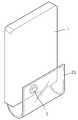
도 1 내지 도 3은 각각 본 발명의 일 실시예에 따른 표시장치를 개략적으로 도시한 측단면도, 정면 사시도 및 배면 사시도이다.FIGS. 1 to 3 are a side sectional view, a front perspective view, and a rear perspective view, respectively, schematically showing a display device according to an embodiment of the present invention.
도 1 내지 도 3의 실시예에 따른 표시 장치는 본체(1)와, 제1표시 유닛(2)과, 카메라 유닛(3)을 포함한다.The display device according to the embodiment of Figs. 1 to 3 includes a
본체(1)는 박스형태의 케이스로 구비되고, 전면(11)에 제1표시 유닛(2)이 결합된다. 본체(1) 내에는 상기 제1표시 유닛(2)과 전기적으로 연결되어 상기 제1표시 유닛(2)을 구동시키기 위한 각종 전자 소자들이 탑재되어 있다.The
본체(1)의 전면(11) 반대측에는 카메라 유닛(3)이 설치된다. 상기 카메라 유닛(3)은 상기 제1표시 유닛(2)과 전기적으로 연결되어 촬상된 화상을 제1표시 유닛(2)을 통해 사용자에게 구현한다.A camera unit (3) is provided on the opposite side of the front face (11) of the main body (1). The camera unit (3) is electrically connected to the first display unit (2) and implements the image captured by the user through the first display unit (2).
상기 제1표시 유닛(2)은 상기 본체(1)에 대향되게 상기 본체(1)와 결합되는 것으로, 평판으로 구비된다. 상기 제1표시 유닛(2)은 외광이 투과되어 제1표시 유닛(2)의 전면에서 봤을 때 본체(1)의 전면(11)이 투시되어 보일 수 있도록 구비된다.The first display unit (2) is coupled to the main body (1) so as to face the main body (1) and is provided as a flat plate. The
상기 제1표시 유닛(2)은 일 방향을 향한 제1면(21)과, 타 방향을 향한 제2면(22)을 갖는다. 상기 제1면(21)을 통해 화상 이미지가 구현된다. 따라서 사용자는 제1표시 유닛(2)에 대하여 제1면(21)의 전방에 위치하고 있다.The first display unit (2) has a first surface (21) oriented in one direction and a second surface (22) oriented in the other direction. An image image is implemented through the first side (21). Therefore, the user is positioned in front of the
한편, 상기 제1표시 유닛(2)은 외광이 상기 제1면(21) 및 제2면(22)을 투과하도록 구비될 수 있다. 따라서 상기 제1표시 유닛(2)에 대하여 제1면(21)의 전방에 위치한 사용자는 제1표시 유닛(2)의 제1면(21) 및 제2면(22)을 투과한 본체(1)의 전면(11)을 관찰할 수 있다.Meanwhile, the
상기 제1표시 유닛(2)은 도 4에서 볼 수 있듯이, 표시부(23)와 터치 센싱부(24)를 포함할 수 있다.The
상기 표시부(23)와 터치 센싱부(24)는 도면에 도시하지 않은 접착 수단에 의해 접합될 수 있는 데, 반드시 이에 한정되는 것은 아니고, 표시부(23)에 증착 형성되는 방법으로 표시부(23)와 일체로 형성될 수 있다.The
상기 터치 센싱부(24)는 정전 센싱 방식의 터치 패널이나, 압력 센싱 방식의 터치 패널이 모두 적용될 수 있다.The touch sensing unit 24 may be a touch panel of an electrostatic sensing type or a touch panel of a pressure sensing type.
도 5 및 도 6은 각각 상기 표시부(23)의 서로 다른 실시예들을 도시한 단면도들이다. 도 5 및 도 6에 도시된 실시예들은 유기 발광 표시장치를 나타낸다.5 and 6 are sectional views showing different embodiments of the
도 5를 참조하면, 본 발명의 일 실시예에 따른 표시부(23)는 기판(231)의 일 면에 형성된 유기 발광부(233)와 이 유기 발광부(233)를 밀봉하는 밀봉 기판(232)을 포함한다.5, a
상기 밀봉기판(232)은 유기 발광부(233)로 외기 및 수분이 침투하는 것을 차단한다. 기판(231) 및 밀봉 기판(232)은 표시부(23)가 밴딩 가능한 플렉시블 표시 장치가 되도록 플라스틱재로 형성될 수 있는 데, 반드시 이에 한정되는 것은 아니고 밴딩 가능한 얇은 글라스재로 형성될 수도 있다.The sealing
상기 기판(231)과 상기 밀봉기판(232)은 그 가장자리가 밀봉재(234)에 의해 결합되어 상기 기판(231)과 밀봉기판(232)의 사이 공간(235)이 밀봉된다. 상기 공간(235)에는 흡습제나 충진재 등이 위치할 수 있다.The edges of the
상기 밀봉기판(232) 대신에 도 6에서 볼 수 있듯이 박막의 밀봉필름(236)을 유기 발광부(233) 상에 형성함으로써 유기 발광부(233)를 외기로부터 보호할 수 있다. 상기 밀봉필름(236)은 실리콘옥사이드 또는 실리콘나이트라이드와 같은 무기물로 이루어진 막과 에폭시, 폴리이미드와 같은 유기물로 이루어진 막이 교대로 성막된 구조를 취할 수 있는 데, 반드시 이에 한정되는 것은 아니며, 투명한 박막 상의 밀봉구조이면 다양하게 적용 가능하다. 플라스틱재로 형성된 기판(231)에 상기 밀봉 필름(236)을 사용할 경우 표시부(23)의 밴딩 특성 및/또는 플렉시빌리티가 더욱 향상될 수 있다.As shown in FIG. 6, a
도 5 및 도 6에 따른 실시예들은 기판(231)의 방향으로 이미지가 구현되는 배면 발광형, 밀봉기판(232) 또는 밀봉필름(236)의 방향으로 이미지가 구현되는 전면발광형, 기판(231)과 밀봉기판(232) 또는 기판(231)과 밀봉필름(236)의 양방향으로 이미지가 구현되는 양면 발광형이 될 수 있다.The embodiments according to FIGS. 5 and 6 are of a top emission type in which an image is implemented in the direction of the
이러한 유기 발광 표시장치는 발광 영역과 투과 영역이 구획되어 투명 및/또는 시스루 표시장치를 구현할 수 있다.In such an OLED display device, a light emitting region and a transmissive region are divided to realize a transparent and / or see-through display device.
이를 위해 상기 유기 발광부(233)는 외광이 투과되는 투과 영역을 갖도록 구비될 수 있는 데, 예컨대 KR 1107178 B1, US 8,193,017 B2, US 8,274,090 B2, US 8,357,938 B2에 개시된 유기 발광부를 적용할 수 있다. 그러나 반드시 이에 한정되는 것은 아니고, 외광이 투과되어 시스루 표시장치를 구현할 수 있는 유기 발광부라면 어떠한 것이든 적용될 수 있다.For example, the organic
상기 표시부(23)는 반드시 유기 발광 표시장치로 구현될 필요는 없으며, 외광이 투과될 수 있는 다양한 평판 표시장치로 구현될 수 있음은 물론이다.It is needless to say that the
도 4에서 볼 때, 상기 터치 센싱부(24)는 도 5에 도시된 표시부(23)의 일 실시예의 밀봉기판(232)의 상부 면에 형성되거나 도 6에 도시된 표시부(23)의 다른 일 실시예의 밀봉 필름(236)의 상부 면에 형성될 수 있다. 그러나 반드시 이에 한정되는 것은 아니고, 상기 터치 센싱부(24)는 도 5 및 도 6에 도시된 표시부(23)의 기판(231)의 하부 면에 형성될 수 있다.4, the touch sensing unit 24 may be formed on the upper surface of the sealing
또는, 상기 터치 센싱부(24)는 표시부(23)의 내부에 형성될 수 있다. 예컨대, 상기 터치 센싱부(24)는 도 5에 도시된 표시부(23)의 밀봉기판(232)의 하부 면, 즉, 밀봉기판(232)과 유기 발광부(233)의 사이에 형성되거나, 기판(231)의 상부 면, 즉, 기판(231)과 유기 발광부(233)의 사이에 형성될 수 있다. 또 상기 터치 센싱부(24)는 도 6에 도시된 표시부(23)의 밀봉필름(236)의 하부 면, 즉, 밀봉필름(236)과 유기 발광부(233)의 사이에 형성되거나, 기판(231)의 상부 면, 즉, 기판(231)과 유기 발광부(233)의 사이에 형성될 수 있다.Alternatively, the touch sensing unit 24 may be formed inside the
도 4에서 볼 때, 상기 표시부(23)와 터치 센싱부(24)가 결합된 조립체가 제1표시 유닛(2)이 되는 데, 제1면(21)은 터치 센싱부(24)의 일 면이, 제2면(22)은 표시부(23)의 일 면이 될 수 있다.4, the assembly in which the
그러나 반드시 이에 한정되는 것은 아니고, 도면에 도시하지는 않았지만 제1면(21)이 표시부(23)의 일면이, 제2면(22)이 터치 센싱부(24)의 일 면이 될 수 있다. 또한, 전술한 바와 같이 터치 센싱부(24)가 표시부(23)의 내부에 형성된 경우에는 상기 제1면(21) 및 제2면(22)은 각각 표시부(23)의 양면이 될 수 있다.Although not shown in the drawings, the
이러한 제1표시 유닛(2)의 실시예들은 이하 설명될 본 발명의 모든 실시예들에 적용될 수 있다.The embodiments of the
다시 도 1 내지 도 3에 도시된 실시예를 참조하면, 상기 본체(1)의 전면(11)에 결합된 제1표시 유닛(2)은 전술한 바와 같이 외광이 투과되고 유연성을 갖는 플렉시블한 평판 표시장치가 채용될 수 있다.1 to 3, the
이 때, 상기 제1표시 유닛(2)은 본체(1)보다 더 길게 형성될 수 있으며, 이에 따라 본체(1)의 외측으로 연장된 부분(25)을 갖는다. 이렇게 연장된 부분(25)은 도 1에서 볼 수 있듯이 본체(1)의 일부를 감아 덮을 수 있는 길이로 구비되어 상기 카메라 유닛(3)과 중첩 가능하도록 구비된다. 따라서 사용자는 제1표시 유닛(2)의 연장된 부분(25)을 선택적으로 구부려 카메라 유닛(3)을 덮도록 하고, 이 상태에서 도 2에서 볼 수 있듯이 카메라 유닛(3)을 조작할 수 있다.At this time, the
상기 연장된 부분(25)은 외광이 투과되도록 유지된 상태에서 별도의 배경 화면이나, 칼라 필터 등의 영상이 구현될 수 있는 데, 이에 따라 사용자는 카메라 유닛(3)을 조작할 때에 다양한 광학적 효과를 얻을 수 있게 된다.The
상기 제1면(21)에는 카메라 유닛(3) 및/또는 연장된 부분(25)의 영상을 조작할 수 있는 조작 버튼이 화상으로 표시될 수 있고, 또 카메라 유닛(3) 및 연장된 부분(25)의 영상이 겹쳐짐에 따른 촬상 영상이 표시될 수 있다.An operation button capable of operating an image of the
그러나 반드시 이에 한정되는 것은 아니다. 도 7에서 볼 수 있듯이 본체(1)가 상기 제1표시 유닛(2)과 중첩되고, 상기 제1표시 유닛(2)의 방향으로 화상을 구현하는 제2표시 유닛(12)을 더 포함할 수 있다. 상기 제1표시 유닛(2)은 외광이 투과되는 상태가 되고, 상기 제2표시 유닛(12)은 다양한 카메라 유닛(3) 및/또는 상기 연장된 부분(25)의 영상을 조작할 수 있는 조작 버튼을 표시할 수 있다. 따라서 사용자는 제2표시 유닛(12)에 의해 구현된 화상을 보고 및/또는 터치함으로써 카메라 유닛(3) 및/또는 상기 연장된 부분(25)의 영상을 조작할 수 있다. 이는 이하 설명될 모든 실시예에도 동일하게 적용될 수 있음은 물론이다.However, the present invention is not limited thereto. 7, the
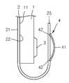
도 8 및 도 9는 본 발명의 또 다른 일 실시예의 표시장치의 일부를 도시한 단면도들로서, 상기 연장된 부분(25)은 상기 카메라 유닛(3)에 광학 기능을 부가하는 광학 조절부(4)를 더 포함할 수 있다.8 and 9 are cross-sectional views showing a part of a display device according to another embodiment of the present invention, wherein the extended
본 발명의 일 실시예에 따르면, 상기 광학 조절부(4)는 렌즈 유닛(41)이 될 수 있다. 상기 렌즈 유닛(41)은 투명하게 구비된 전기 활성 폴리머로 구비될 수 있는 데, 적어도 그 가장자리가 전극(42)에 전기적으로 연결되어 있다. 상기 전극(42)은 상기 제1표시 유닛(2)의 연장된 부분(25)에 매립 형성될 수 있는 데, 반드시 이에 한정되는 것은 아니고, 제1표시 유닛(2)의 연장된 부분(25)의 표면에 형성될 수도 있다. 상기 전극(42)은 도시되지 않았지만 상기 제1표시 유닛(2)의 내부에 형성된 배선을 따라 본체(1) 내부에 탑재된 제어 수단에 전기적으로 연결되며, 전술한 바와 같이 제1표시 유닛(2)의 제1면(21)을 통해 표시되는 조작 버튼의 영상을 터치함으로써 조작될 수 있다.According to an embodiment of the present invention, the
상기 전극(42)에 전원이 인가되면 상기 렌즈 유닛(41)은 특정 형상을 갖도록 변형될 수 있는 데, 예컨대 도 9에서 볼 수 있듯이 볼록 렌즈를 구현할 수 있다.When power is applied to the
상기 연장된 부분(25)을 카메라 유닛(3)과 중첩시킨 상태에서 사용자가 렌즈 유닛(41)을 구동시킴으로써 카메라 유닛(3)에 광학적 렌즈 효과를 부여할 수 있다. 따라서 카메라 유닛(3)을 저사양의 것으로 적용하여도 사용자가 원하는 높은 퀄리티의 촬영 이미지를 얻을 수 있다.The user can give the optical lens effect to the
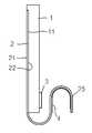
도 10은 본 발명의 또 다른 일 실시예를 도시한 것으로, 상기 연장된 부분(25)은 광학 조절부(4)를 더 포함할 수 있다.FIG. 10 illustrates another embodiment of the present invention, wherein the extended
상기 광학 조절부(4)는 도 8 및 도 9의 실시예에 개시된 렌즈 유닛(41)일 수 있는 데, 반드시 이에 한정된 것은 아니고, 투과되는 빛의 색상을 변환시키는 색 변환 유닛일 수 있다. 예컨대, 전기가 인가되면 특정 색상으로 변색하는 전기 변색 유닛을 포함할 수 있고, 전기의 인가 여부와 관계 없이 특정 색상의 빛을 더욱 강조할 수 있는 칼라 필터 유닛을 포함할 수도 있다.The
사용자는 이러한 광학 조절부(4)를 포함한 상기 연장된 부분(25)을 카메라 유닛(3)의 앞에서 앞뒤로 이동시키면 줌 인 및 줌 아웃을 하는 것과 같은 광학적 효과를 얻을 수 있다.The user can obtain optical effects such as zooming in and zooming out by moving the extended
또, 도 11에서 볼 수 있듯이 상기 연장된 부분(25)을 카메라 유닛(3)과 겹치게 복수회 밴딩시킬 경우 다중 렌즈를 사용한 것과 같은 효과를 얻을 수도 있다.In addition, as shown in FIG. 11, when the
이상 설명한 실시예들에서 상기 본체(1)는 상기 제1표시 유닛(2)의 상기 연장된 부분(25)을 제외한 영역과 중첩되는 크기로 형성되었으나, 본 발명이 반드시 이에 한정되는 것은 아니고, 카메라 유닛(3)보다 약간 큰 정도로 구비될 수 있다.In the above-described embodiments, the
카메라 유닛(3)도 본체(1)의 아래쪽에 위치하는 것으로 도시하였으나 반드시 이에 한정되는 것은 아니고, 본체(1)의 위쪽에 위치할 수 있다. 이 경우, 상기 연장된 부분(25)은 제1표시 유닛(2)의 위쪽에 위치함으로써 위로부터 본체(1)에 중첩되도록 밴딩될 수 있다.Although the
본 발명은 첨부된 도면에 도시된 일 실시예를 참고로 설명되었으나 이는 예시적인 것에 불과하며, 당해 기술분야에서 통상의 지식을 가진 자라면 이로부터 다양한 변형 및 균등한 타 실시예가 가능하다는 점을 이해할 수 있을 것이다. 따라서 본 발명의 진정한 보호 범위는 첨부된 청구 범위에 의해서만 정해져야 할 것이다.While the present invention has been particularly shown and described with reference to exemplary embodiments thereof, it is clearly understood that the same is by way of illustration and example only and is not to be taken by way of limitation and that those skilled in the art will recognize that various modifications and equivalent arrangements may be made therein. It will be possible. Accordingly, the true scope of protection of the present invention should be determined only by the appended claims.
Claims (11)
Translated fromKorean상기 본체와 대향하도록 구비되고, 서로 반대 방향을 향하는 제1면 및 제2면을 가지며, 상기 제1면을 통해 화상이 구현되고 상기 제2면이 상기 본체를 향하도록 구비된 제1표시 유닛; 및
상기 본체에 설치된 카메라 유닛;을 포함하고,
상기 제1표시 유닛은, 외광이 상기 제1면 및 제2면을 투과하고 상기 카메라 유닛의 전방으로 선택적으로 밴딩되도록 구비되고 상기 카메라 유닛에 광학 기능을 부가하는 광학 조절부를 포함하는 표시 장치.main body;
A first display unit provided to face the main body and having a first surface and a second surface facing each other in opposite directions, the image being realized through the first surface and the second surface facing the main body; And
And a camera unit installed in the main body,
Wherein the first display unit includes an optical adjusting unit that is provided to allow external light to pass through the first and second surfaces and selectively bend forwardly of the camera unit and to add an optical function to the camera unit.
상기 제1표시 유닛은 터치 센싱부를 더 포함하는 표시 장치.The method according to claim 1,
Wherein the first display unit further comprises a touch sensing unit.
상기 터치 센싱부는 상기 제1면에 위치하는 표시 장치.3. The method of claim 2,
And the touch sensing unit is located on the first surface.
상기 광학 조절부는, 전극 및 상기 전극에 전기적으로 연결되고 투명하며 전기 활성 폴리머를 포함하는 선택적 렌즈 유닛을 더 포함하는 표시 장치.The method according to claim 1,
Wherein the optical control unit further comprises an electrode and a selective lens unit electrically connected to the electrode and including a transparent and electroactive polymer.
상기 광학 조절부는, 투과되는 빛의 색상을 변환시키는 색 변환 유닛을 더 포함하는 표시 장치.The method according to claim 1,
Wherein the optical control unit further comprises a color conversion unit for converting the color of the transmitted light.
상기 본체는, 상기 제1표시 유닛과 중첩되고, 상기 제1표시 유닛의 방향으로 화상을 구현하는 제2표시 유닛을 더 포함하며,
상기 제1표시 유닛은 외광이 상기 제1면 및 제2면을 투과하도록 구비되어 상기 제1면을 통해 상기 제2표시 유닛의 화상이 투시되도록 구비된 표시 장치.The method according to claim 1,
The main body further comprises a second display unit superimposed on the first display unit and embodying an image in the direction of the first display unit,
Wherein the first display unit is provided so that external light transmits through the first surface and the second surface so that an image of the second display unit is viewed through the first surface.
상기 본체와 결합된 제1표시 유닛을 포함하되, 상기 제1표시 유닛은 서로 반대 방향을 향하는 제1면 및 제2면을 갖고, 상기 제1면을 통해 화상이 구현되고 상기 제2면이 상기 본체를 향하도록 구비되며, 외광이 상기 제1면 및 제2면을 투과하도록 구비된 제1표시 유닛;을 포함하고,
상기 제1표시 유닛은 상기 본체의 외측으로 연장된 부분을 포함하고, 상기 연장된 부분이 상기 카메라 유닛과 중첩되게 선택적으로 밴딩되도록 구비된 표시 장치.A main body having a camera unit installed therein; And
And a first display unit coupled to the main body, wherein the first display unit has a first surface and a second surface facing each other in opposite directions, an image is realized through the first surface, And a first display unit provided to face the main body and configured to transmit external light through the first surface and the second surface,
Wherein the first display unit includes an outwardly extending portion of the body, and the extended portion is selectively bent so as to overlap with the camera unit.
상기 제1표시 유닛은 플렉시블하게 구비된 표시 장치.8. The method of claim 7,
And the first display unit is provided flexibly.
상기 제1표시 유닛은 상기 연장된 부분에 렌즈 유닛을 더 포함하고,
상기 렌즈 유닛은, 전극 및 상기 전극에 전기적으로 연결되고 투명하며 전기 활성 폴리머를 포함하는 표시 장치.8. The method of claim 7,
Wherein the first display unit further comprises a lens unit at the extended portion,
Wherein the lens unit comprises an electrode and a transparent electrically conductive polymer electrically connected to the electrode.
상기 제1표시 유닛은 상기 연장된 부분에 투과되는 빛의 색상을 변환시키는 색 변환 유닛을 더 포함하는 표시 장치.8. The method of claim 7,
Wherein the first display unit further comprises a color conversion unit for converting a color of light transmitted through the extended portion.
상기 본체는, 상기 제1표시 유닛과 중첩되고, 상기 제1표시 유닛의 방향으로 화상을 구현하는 제2표시 유닛을 더 포함하는 표시 장치.8. The method of claim 7,
Wherein the main body further comprises a second display unit which overlaps with the first display unit and implements an image in the direction of the first display unit.
Priority Applications (4)
| Application Number | Priority Date | Filing Date | Title |
|---|---|---|---|
| KR1020130041259AKR20140123861A (en) | 2013-04-15 | 2013-04-15 | Display device |
| US14/032,926US9369622B2 (en) | 2013-04-15 | 2013-09-20 | Portable device with camera |
| TW102139215ATW201440518A (en) | 2013-04-15 | 2013-10-30 | Display device, portable device and method of operating the portable device |
| CN201310681805.2ACN104104847A (en) | 2013-04-15 | 2013-12-12 | Display device, portable device and method for operating portable device |
Applications Claiming Priority (1)
| Application Number | Priority Date | Filing Date | Title |
|---|---|---|---|
| KR1020130041259AKR20140123861A (en) | 2013-04-15 | 2013-04-15 | Display device |
Publications (1)
| Publication Number | Publication Date |
|---|---|
| KR20140123861Atrue KR20140123861A (en) | 2014-10-23 |
Family
ID=51672625
Family Applications (1)
| Application Number | Title | Priority Date | Filing Date |
|---|---|---|---|
| KR1020130041259AWithdrawnKR20140123861A (en) | 2013-04-15 | 2013-04-15 | Display device |
Country Status (4)
| Country | Link |
|---|---|
| US (1) | US9369622B2 (en) |
| KR (1) | KR20140123861A (en) |
| CN (1) | CN104104847A (en) |
| TW (1) | TW201440518A (en) |
Families Citing this family (12)
| Publication number | Priority date | Publication date | Assignee | Title |
|---|---|---|---|---|
| KR102358935B1 (en) | 2014-02-12 | 2022-02-04 | 가부시키가이샤 한도오따이 에네루기 켄큐쇼 | Electronic device |
| KR20160058329A (en)* | 2014-11-14 | 2016-05-25 | 삼성디스플레이 주식회사 | Flexible display device |
| KR102406091B1 (en)* | 2015-04-01 | 2022-06-10 | 삼성전자주식회사 | Electronic device |
| EP3113477B1 (en) | 2015-06-30 | 2017-08-02 | Axis AB | Monitoring camera |
| CN105388973B (en)* | 2015-11-13 | 2019-03-19 | 业成光电(深圳)有限公司 | Portable electronic devices |
| CN106355999A (en)* | 2016-10-12 | 2017-01-25 | 武汉华星光电技术有限公司 | Flexible OLED (organic light emitting diode) display screen and application method thereof |
| TWI619372B (en)* | 2016-11-01 | 2018-03-21 | Ultra-wide depth stereoscopic image system and method | |
| KR102323245B1 (en)* | 2017-03-15 | 2021-11-08 | 삼성디스플레이 주식회사 | Manufacturing method for display device and thin-film deposition apparatus using thereof |
| KR102546667B1 (en)* | 2018-05-15 | 2023-06-23 | 삼성디스플레이 주식회사 | Foldable display device |
| CN112655194B (en) | 2018-09-11 | 2022-07-19 | 三星电子株式会社 | Electronic device and method for capturing views |
| CN113993931B (en) | 2019-04-23 | 2024-01-23 | 杜邦电子公司 | Polymers used in electronic devices |
| CN112289184B (en)* | 2020-10-26 | 2022-09-09 | 武汉华星光电半导体显示技术有限公司 | Display panel and display device |
Family Cites Families (13)
| Publication number | Priority date | Publication date | Assignee | Title |
|---|---|---|---|---|
| KR100650190B1 (en) | 2005-07-19 | 2006-11-27 | 삼성전기주식회사 | Light control device using electroactive polymer |
| US20080247749A1 (en)* | 2007-04-03 | 2008-10-09 | David Law | Camera Wrap Cover |
| US8154582B2 (en)* | 2007-10-19 | 2012-04-10 | Eastman Kodak Company | Display device with capture capabilities |
| KR101482125B1 (en) | 2008-09-09 | 2015-01-13 | 엘지전자 주식회사 | A portable terminal and its operation method |
| KR20110128929A (en)* | 2009-03-18 | 2011-11-30 | 바이엘 머티리얼사이언스 아게 | Wafer level optical system |
| KR101067661B1 (en) | 2009-04-14 | 2011-09-27 | 한국과학기술원 | Flexible display shape changing device using electro-active polymer operated by ion and method |
| KR101107178B1 (en) | 2009-07-20 | 2012-01-25 | 삼성모바일디스플레이주식회사 | Organic light emitting display |
| US8890771B2 (en) | 2010-01-06 | 2014-11-18 | Apple Inc. | Transparent electronic device |
| KR101108170B1 (en) | 2010-03-15 | 2012-01-31 | 삼성모바일디스플레이주식회사 | OLED display and manufacturing method thereof |
| KR20120019026A (en) | 2010-08-24 | 2012-03-06 | 삼성모바일디스플레이주식회사 | Organic light emitting display device |
| KR101714539B1 (en) | 2010-08-24 | 2017-03-23 | 삼성디스플레이 주식회사 | Organic light emitting display device |
| US9143668B2 (en)* | 2010-10-29 | 2015-09-22 | Apple Inc. | Camera lens structures and display structures for electronic devices |
| US9022575B2 (en)* | 2011-03-23 | 2015-05-05 | Microsoft Technology Licensing, Llc | Flexible mobile display |
- 2013
- 2013-04-15KRKR1020130041259Apatent/KR20140123861A/ennot_activeWithdrawn
- 2013-09-20USUS14/032,926patent/US9369622B2/enactiveActive
- 2013-10-30TWTW102139215Apatent/TW201440518A/enunknown
- 2013-12-12CNCN201310681805.2Apatent/CN104104847A/enactivePending
Also Published As
| Publication number | Publication date |
|---|---|
| US9369622B2 (en) | 2016-06-14 |
| CN104104847A (en) | 2014-10-15 |
| TW201440518A (en) | 2014-10-16 |
| US20140307144A1 (en) | 2014-10-16 |
Similar Documents
| Publication | Publication Date | Title |
|---|---|---|
| KR20140123861A (en) | Display device | |
| CN105789255B (en) | Flexible display panel with curved substrate | |
| CN109743426B (en) | electronic device | |
| KR102794249B1 (en) | Electronic device including a display | |
| KR102018741B1 (en) | Display device with cover window | |
| KR102699192B1 (en) | Display device | |
| US10509470B2 (en) | Vibrating device | |
| US10587738B2 (en) | Display module and electronic device | |
| KR102582263B1 (en) | Display device and method for manufacturing the same | |
| JP6895524B2 (en) | Display screen assemblies, how to assemble display screen assemblies, and electronic devices | |
| KR102079095B1 (en) | Display apparatus | |
| CN110837313B (en) | Display device | |
| KR20160119914A (en) | Display device | |
| CN111443762A (en) | display device | |
| US10359880B2 (en) | Touch sensitive display device | |
| EP4358495A1 (en) | Electronic device comprising display support structure | |
| KR20210029431A (en) | Electronic device including camera module | |
| JP5740477B2 (en) | Display device | |
| KR102733586B1 (en) | Display device | |
| KR20210029618A (en) | Electronic device including camera module | |
| US20140198468A1 (en) | Flat panel display device | |
| CN113132874A (en) | Flexible diaphragm and display device having the same | |
| KR102734407B1 (en) | Display device | |
| JPWO2014132629A1 (en) | Tactile presentation device | |
| US20250021132A1 (en) | Electronic device including flexible display |
Legal Events
| Date | Code | Title | Description |
|---|---|---|---|
| PA0109 | Patent application | Patent event code:PA01091R01D Comment text:Patent Application Patent event date:20130415 | |
| PG1501 | Laying open of application | ||
| PC1203 | Withdrawal of no request for examination | ||
| WITN | Application deemed withdrawn, e.g. because no request for examination was filed or no examination fee was paid |