KR20140122751A - Droplet formation using fluid breakup - Google Patents
Droplet formation using fluid breakupDownload PDFInfo
- Publication number
- KR20140122751A KR20140122751AKR1020147024779AKR20147024779AKR20140122751AKR 20140122751 AKR20140122751 AKR 20140122751AKR 1020147024779 AKR1020147024779 AKR 1020147024779AKR 20147024779 AKR20147024779 AKR 20147024779AKR 20140122751 AKR20140122751 AKR 20140122751A
- Authority
- KR
- South Korea
- Prior art keywords
- fluid
- droplets
- continuous
- create
- channel
- Prior art date
- Legal status (The legal status is an assumption and is not a legal conclusion. Google has not performed a legal analysis and makes no representation as to the accuracy of the status listed.)
- Withdrawn
Links
- 239000012530fluidSubstances0.000titleclaimsabstractdescription455
- 230000015572biosynthetic processEffects0.000titleabstractdescription32
- 238000000034methodMethods0.000claimsabstractdescription86
- 239000007788liquidSubstances0.000claimsdescription24
- 238000003780insertionMethods0.000claimsdescription19
- 230000037431insertionEffects0.000claimsdescription19
- 239000006185dispersionSubstances0.000claimsdescription10
- 238000011144upstream manufacturingMethods0.000claimsdescription8
- 238000009826distributionMethods0.000claimsdescription7
- 239000000839emulsionSubstances0.000description26
- 239000000463materialSubstances0.000description26
- 229920000642polymerPolymers0.000description25
- 239000003921oilSubstances0.000description16
- 229920000435poly(dimethylsiloxane)Polymers0.000description16
- 235000013870dimethyl polysiloxaneNutrition0.000description15
- XLYOFNOQVPJJNP-UHFFFAOYSA-NwaterSubstancesOXLYOFNOQVPJJNP-UHFFFAOYSA-N0.000description14
- 239000004205dimethyl polysiloxaneSubstances0.000description13
- KBPLFHHGFOOTCA-UHFFFAOYSA-N1-OctanolChemical compoundCCCCCCCCOKBPLFHHGFOOTCA-UHFFFAOYSA-N0.000description12
- 239000000499gelSubstances0.000description12
- -1polydimethylsiloxanePolymers0.000description11
- XUIMIQQOPSSXEZ-UHFFFAOYSA-NSiliconChemical compound[Si]XUIMIQQOPSSXEZ-UHFFFAOYSA-N0.000description10
- 230000002209hydrophobic effectEffects0.000description10
- 230000009977dual effectEffects0.000description9
- 230000000694effectsEffects0.000description9
- 239000007789gasSubstances0.000description9
- 239000010703siliconSubstances0.000description9
- 229910052710siliconInorganic materials0.000description9
- 229920005573silicon-containing polymerPolymers0.000description9
- 238000004519manufacturing processMethods0.000description8
- 229910000077silaneInorganic materials0.000description8
- 150000004756silanesChemical class0.000description8
- BLRPTPMANUNPDV-UHFFFAOYSA-NSilaneChemical compound[SiH4]BLRPTPMANUNPDV-UHFFFAOYSA-N0.000description7
- 230000005587bubblingEffects0.000description7
- NBVXSUQYWXRMNV-UHFFFAOYSA-NfluoromethaneChemical compoundFCNBVXSUQYWXRMNV-UHFFFAOYSA-N0.000description7
- 230000007246mechanismEffects0.000description7
- VYPSYNLAJGMNEJ-UHFFFAOYSA-NSilicium dioxideChemical compoundO=[Si]=OVYPSYNLAJGMNEJ-UHFFFAOYSA-N0.000description6
- 239000007864aqueous solutionSubstances0.000description6
- 230000006870functionEffects0.000description6
- 239000011521glassSubstances0.000description6
- 239000012071phaseSubstances0.000description6
- 239000000758substrateSubstances0.000description6
- 230000001960triggered effectEffects0.000description6
- 239000004593EpoxySubstances0.000description5
- 125000000524functional groupChemical group0.000description5
- 230000008901benefitEffects0.000description4
- 150000001875compoundsChemical class0.000description4
- 229920001296polysiloxanePolymers0.000description4
- 230000008569processEffects0.000description4
- 238000005086pumpingMethods0.000description4
- 238000007789sealingMethods0.000description4
- 238000000926separation methodMethods0.000description4
- 229910052814silicon oxideInorganic materials0.000description4
- 239000002904solventSubstances0.000description4
- 238000006243chemical reactionMethods0.000description3
- 239000013626chemical specieSubstances0.000description3
- 239000003795chemical substances by applicationSubstances0.000description3
- 239000011248coating agentSubstances0.000description3
- 238000000576coating methodMethods0.000description3
- 229920001971elastomerPolymers0.000description3
- 239000000806elastomerSubstances0.000description3
- 238000002347injectionMethods0.000description3
- 239000007924injectionSubstances0.000description3
- 239000000243solutionSubstances0.000description3
- 239000000126substanceSubstances0.000description3
- NGDLSKPZMOTRTR-OAPYJULQSA-N(4z)-4-heptadecylidene-3-hexadecyloxetan-2-oneChemical compoundCCCCCCCCCCCCCCCC\C=C1/OC(=O)C1CCCCCCCCCCCCCCCCNGDLSKPZMOTRTR-OAPYJULQSA-N0.000description2
- OKTJSMMVPCPJKN-UHFFFAOYSA-NCarbonChemical compound[C]OKTJSMMVPCPJKN-UHFFFAOYSA-N0.000description2
- 239000004215Carbon black (E152)Substances0.000description2
- LFQSCWFLJHTTHZ-UHFFFAOYSA-NEthanolChemical compoundCCOLFQSCWFLJHTTHZ-UHFFFAOYSA-N0.000description2
- 239000004698PolyethyleneSubstances0.000description2
- 239000004793PolystyreneSubstances0.000description2
- 229910052581Si3N4Inorganic materials0.000description2
- 229910004298SiO 2Inorganic materials0.000description2
- BOTDANWDWHJENH-UHFFFAOYSA-NTetraethyl orthosilicateChemical compoundCCO[Si](OCC)(OCC)OCCBOTDANWDWHJENH-UHFFFAOYSA-N0.000description2
- GWEVSGVZZGPLCZ-UHFFFAOYSA-NTitan oxideChemical compoundO=[Ti]=OGWEVSGVZZGPLCZ-UHFFFAOYSA-N0.000description2
- 239000000853adhesiveSubstances0.000description2
- 230000001070adhesive effectEffects0.000description2
- QVGXLLKOCUKJST-UHFFFAOYSA-Natomic oxygenChemical compound[O]QVGXLLKOCUKJST-UHFFFAOYSA-N0.000description2
- IISBACLAFKSPIT-UHFFFAOYSA-Nbisphenol AChemical compoundC=1C=C(O)C=CC=1C(C)(C)C1=CC=C(O)C=C1IISBACLAFKSPIT-UHFFFAOYSA-N0.000description2
- 229910052799carbonInorganic materials0.000description2
- 239000013536elastomeric materialSubstances0.000description2
- 230000001747exhibiting effectEffects0.000description2
- DCAYPVUWAIABOU-UHFFFAOYSA-NhexadecaneChemical compoundCCCCCCCCCCCCCCCCDCAYPVUWAIABOU-UHFFFAOYSA-N0.000description2
- 229930195733hydrocarbonNatural products0.000description2
- 150000002430hydrocarbonsChemical class0.000description2
- 229910044991metal oxideInorganic materials0.000description2
- 150000004706metal oxidesChemical class0.000description2
- 239000000203mixtureSubstances0.000description2
- 230000001590oxidative effectEffects0.000description2
- 239000001301oxygenSubstances0.000description2
- 229910052760oxygenInorganic materials0.000description2
- 239000002245particleSubstances0.000description2
- 229920000573polyethylenePolymers0.000description2
- 238000006116polymerization reactionMethods0.000description2
- 229920002223polystyrenePolymers0.000description2
- 239000010453quartzSubstances0.000description2
- HQVNEWCFYHHQES-UHFFFAOYSA-Nsilicon nitrideChemical compoundN12[Si]34N5[Si]62N3[Si]51N64HQVNEWCFYHHQES-UHFFFAOYSA-N0.000description2
- 229920002545silicone oilPolymers0.000description2
- 239000007787solidSubstances0.000description2
- 241000894007speciesSpecies0.000description2
- CPUDPFPXCZDNGI-UHFFFAOYSA-Ntriethoxy(methyl)silaneChemical compoundCCO[Si](C)(OCC)OCCCPUDPFPXCZDNGI-UHFFFAOYSA-N0.000description2
- SVQLLPOUSBWFHB-UHFFFAOYSA-N1-(1,2,2,3,3,4,4,5,5,6,6-undecafluorocyclohexyl)ethanolChemical compoundCC(O)C1(F)C(F)(F)C(F)(F)C(F)(F)C(F)(F)C1(F)FSVQLLPOUSBWFHB-UHFFFAOYSA-N0.000description1
- HHBBIOLEJRWIGU-UHFFFAOYSA-N4-ethoxy-1,1,1,2,2,3,3,4,5,6,6,6-dodecafluoro-5-(trifluoromethyl)hexaneChemical compoundCCOC(F)(C(F)(C(F)(F)F)C(F)(F)F)C(F)(F)C(F)(F)C(F)(F)FHHBBIOLEJRWIGU-UHFFFAOYSA-N0.000description1
- 229910018072Al 2 O 3Inorganic materials0.000description1
- 239000005046ChlorosilaneSubstances0.000description1
- 239000004821Contact adhesiveSubstances0.000description1
- 229910008051Si-OHInorganic materials0.000description1
- 229910006358Si—OHInorganic materials0.000description1
- DBMJMQXJHONAFJ-UHFFFAOYSA-MSodium laurylsulphateChemical compound[Na+].CCCCCCCCCCCCOS([O-])(=O)=ODBMJMQXJHONAFJ-UHFFFAOYSA-M0.000description1
- 239000004809TeflonSubstances0.000description1
- 229920006362Teflon®Polymers0.000description1
- 229910010413TiO 2Inorganic materials0.000description1
- DCEAIJSAWZPVQY-UHFFFAOYSA-N[SiH4].CO[Si](CCCNCCN)(OC)OCChemical class[SiH4].CO[Si](CCCNCCN)(OC)OCDCEAIJSAWZPVQY-UHFFFAOYSA-N0.000description1
- 239000002253acidSubstances0.000description1
- 230000002411adverseEffects0.000description1
- 150000004703alkoxidesChemical group0.000description1
- PNEYBMLMFCGWSK-UHFFFAOYSA-Naluminium oxideInorganic materials[O-2].[O-2].[O-2].[Al+3].[Al+3]PNEYBMLMFCGWSK-UHFFFAOYSA-N0.000description1
- 150000001412aminesChemical group0.000description1
- 150000003863ammonium saltsChemical class0.000description1
- 238000013459approachMethods0.000description1
- 150000004982aromatic aminesChemical class0.000description1
- 230000003542behavioural effectEffects0.000description1
- 239000008366buffered solutionSubstances0.000description1
- 239000002775capsuleSubstances0.000description1
- 238000005266castingMethods0.000description1
- 230000008859changeEffects0.000description1
- 238000005229chemical vapour depositionMethods0.000description1
- VNJCDDZVNHPVNM-UHFFFAOYSA-Nchloro(ethyl)silaneChemical compoundCC[SiH2]ClVNJCDDZVNHPVNM-UHFFFAOYSA-N0.000description1
- YGZSVWMBUCGDCV-UHFFFAOYSA-Nchloro(methyl)silaneChemical compoundC[SiH2]ClYGZSVWMBUCGDCV-UHFFFAOYSA-N0.000description1
- GTPDFCLBTFKHNH-UHFFFAOYSA-Nchloro(phenyl)siliconChemical compoundCl[Si]C1=CC=CC=C1GTPDFCLBTFKHNH-UHFFFAOYSA-N0.000description1
- KOPOQZFJUQMUML-UHFFFAOYSA-NchlorosilaneChemical classCl[SiH3]KOPOQZFJUQMUML-UHFFFAOYSA-N0.000description1
- 238000004581coalescenceMethods0.000description1
- 239000000084colloidal systemSubstances0.000description1
- 238000004891communicationMethods0.000description1
- 239000011258core-shell materialSubstances0.000description1
- 150000004292cyclic ethersChemical group0.000description1
- 230000001419dependent effectEffects0.000description1
- 238000005137deposition processMethods0.000description1
- 238000010586diagramMethods0.000description1
- GYZLOYUZLJXAJU-UHFFFAOYSA-Ndiglycidyl etherChemical compoundC1OC1COCC1CO1GYZLOYUZLJXAJU-UHFFFAOYSA-N0.000description1
- KPUWHANPEXNPJT-UHFFFAOYSA-NdisiloxaneChemical class[SiH3]O[SiH3]KPUWHANPEXNPJT-UHFFFAOYSA-N0.000description1
- 238000004945emulsificationMethods0.000description1
- 238000005530etchingMethods0.000description1
- 238000001704evaporationMethods0.000description1
- 230000008020evaporationEffects0.000description1
- 238000001914filtrationMethods0.000description1
- 229910052731fluorineInorganic materials0.000description1
- 125000001153fluoro groupChemical groupF*0.000description1
- 238000011010flushing procedureMethods0.000description1
- 238000009652hydrodynamic focusingMethods0.000description1
- 229920001600hydrophobic polymerPolymers0.000description1
- 238000001746injection mouldingMethods0.000description1
- 239000008384inner phaseSubstances0.000description1
- 230000001788irregularEffects0.000description1
- 238000005304joiningMethods0.000description1
- 125000003473lipid groupChemical group0.000description1
- 230000008018meltingEffects0.000description1
- 238000002844meltingMethods0.000description1
- 238000005459micromachiningMethods0.000description1
- 239000002480mineral oilSubstances0.000description1
- 235000010446mineral oilNutrition0.000description1
- 238000002156mixingMethods0.000description1
- 238000012986modificationMethods0.000description1
- 230000004048modificationEffects0.000description1
- 238000000465mouldingMethods0.000description1
- 229920003986novolacPolymers0.000description1
- YTJSFYQNRXLOIC-UHFFFAOYSA-NoctadecylsilaneChemical compoundCCCCCCCCCCCCCCCCCC[SiH3]YTJSFYQNRXLOIC-UHFFFAOYSA-N0.000description1
- SLYCYWCVSGPDFR-UHFFFAOYSA-NoctadecyltrimethoxysilaneChemical groupCCCCCCCCCCCCCCCCCC[Si](OC)(OC)OCSLYCYWCVSGPDFR-UHFFFAOYSA-N0.000description1
- 239000007800oxidant agentSubstances0.000description1
- 230000003647oxidationEffects0.000description1
- 238000007254oxidation reactionMethods0.000description1
- 229950011087perflunafeneDrugs0.000description1
- UWEYRJFJVCLAGH-UHFFFAOYSA-NperfluorodecalinChemical compoundFC1(F)C(F)(F)C(F)(F)C(F)(F)C2(F)C(F)(F)C(F)(F)C(F)(F)C(F)(F)C21FUWEYRJFJVCLAGH-UHFFFAOYSA-N0.000description1
- 230000000737periodic effectEffects0.000description1
- 230000000704physical effectEffects0.000description1
- 229920000058polyacrylatePolymers0.000description1
- 229920000728polyesterPolymers0.000description1
- 239000012704polymeric precursorSubstances0.000description1
- 229920001343polytetrafluoroethylenePolymers0.000description1
- 239000004810polytetrafluoroethyleneSubstances0.000description1
- 239000002243precursorSubstances0.000description1
- 238000003825pressingMethods0.000description1
- 238000012545processingMethods0.000description1
- 239000000376reactantSubstances0.000description1
- 238000009877renderingMethods0.000description1
- 238000000820replica mouldingMethods0.000description1
- 150000003839saltsChemical class0.000description1
- 238000004062sedimentationMethods0.000description1
- SCPYDCQAZCOKTP-UHFFFAOYSA-NsilanolChemical compound[SiH3]OSCPYDCQAZCOKTP-UHFFFAOYSA-N0.000description1
- 125000005372silanol groupChemical group0.000description1
- 229920002379silicone rubberPolymers0.000description1
- 238000002174soft lithographyMethods0.000description1
- 239000011343solid materialSubstances0.000description1
- 238000000935solvent evaporationMethods0.000description1
- 238000004528spin coatingMethods0.000description1
- 239000004094surface-active agentSubstances0.000description1
- 238000012360testing methodMethods0.000description1
- BFKJFAAPBSQJPD-UHFFFAOYSA-NtetrafluoroetheneChemical groupFC(F)=C(F)FBFKJFAAPBSQJPD-UHFFFAOYSA-N0.000description1
- 229920001169thermoplasticPolymers0.000description1
- 229920001187thermosetting polymerPolymers0.000description1
- 239000012780transparent materialSubstances0.000description1
- 150000003918triazinesChemical class0.000description1
- 238000003466weldingMethods0.000description1
Images


Classifications
- B—PERFORMING OPERATIONS; TRANSPORTING
- B01—PHYSICAL OR CHEMICAL PROCESSES OR APPARATUS IN GENERAL
- B01F—MIXING, e.g. DISSOLVING, EMULSIFYING OR DISPERSING
- B01F23/00—Mixing according to the phases to be mixed, e.g. dispersing or emulsifying
- B01F23/40—Mixing liquids with liquids; Emulsifying
- B01F23/405—Methods of mixing liquids with liquids
- B—PERFORMING OPERATIONS; TRANSPORTING
- B01—PHYSICAL OR CHEMICAL PROCESSES OR APPARATUS IN GENERAL
- B01F—MIXING, e.g. DISSOLVING, EMULSIFYING OR DISPERSING
- B01F23/00—Mixing according to the phases to be mixed, e.g. dispersing or emulsifying
- B01F23/40—Mixing liquids with liquids; Emulsifying
- B01F23/41—Emulsifying
- B—PERFORMING OPERATIONS; TRANSPORTING
- B01—PHYSICAL OR CHEMICAL PROCESSES OR APPARATUS IN GENERAL
- B01F—MIXING, e.g. DISSOLVING, EMULSIFYING OR DISPERSING
- B01F23/00—Mixing according to the phases to be mixed, e.g. dispersing or emulsifying
- B01F23/40—Mixing liquids with liquids; Emulsifying
- B01F23/45—Mixing liquids with liquids; Emulsifying using flow mixing
- B01F23/451—Mixing liquids with liquids; Emulsifying using flow mixing by injecting one liquid into another
- B—PERFORMING OPERATIONS; TRANSPORTING
- B01—PHYSICAL OR CHEMICAL PROCESSES OR APPARATUS IN GENERAL
- B01F—MIXING, e.g. DISSOLVING, EMULSIFYING OR DISPERSING
- B01F25/00—Flow mixers; Mixers for falling materials, e.g. solid particles
- B01F25/30—Injector mixers
- B01F25/31—Injector mixers in conduits or tubes through which the main component flows
- B01F25/314—Injector mixers in conduits or tubes through which the main component flows wherein additional components are introduced at the circumference of the conduit
- B—PERFORMING OPERATIONS; TRANSPORTING
- B01—PHYSICAL OR CHEMICAL PROCESSES OR APPARATUS IN GENERAL
- B01F—MIXING, e.g. DISSOLVING, EMULSIFYING OR DISPERSING
- B01F33/00—Other mixers; Mixing plants; Combinations of mixers
- B01F33/30—Micromixers
- B—PERFORMING OPERATIONS; TRANSPORTING
- B01—PHYSICAL OR CHEMICAL PROCESSES OR APPARATUS IN GENERAL
- B01F—MIXING, e.g. DISSOLVING, EMULSIFYING OR DISPERSING
- B01F25/00—Flow mixers; Mixers for falling materials, e.g. solid particles
- B01F25/14—Mixing drops, droplets or bodies of liquid which flow together or contact each other
- B—PERFORMING OPERATIONS; TRANSPORTING
- B01—PHYSICAL OR CHEMICAL PROCESSES OR APPARATUS IN GENERAL
- B01L—CHEMICAL OR PHYSICAL LABORATORY APPARATUS FOR GENERAL USE
- B01L2200/00—Solutions for specific problems relating to chemical or physical laboratory apparatus
- B01L2200/06—Fluid handling related problems
- B01L2200/0673—Handling of plugs of fluid surrounded by immiscible fluid
- B—PERFORMING OPERATIONS; TRANSPORTING
- B01—PHYSICAL OR CHEMICAL PROCESSES OR APPARATUS IN GENERAL
- B01L—CHEMICAL OR PHYSICAL LABORATORY APPARATUS FOR GENERAL USE
- B01L3/00—Containers or dishes for laboratory use, e.g. laboratory glassware; Droppers
- B01L3/02—Burettes; Pipettes
- B01L3/0241—Drop counters; Drop formers
- B—PERFORMING OPERATIONS; TRANSPORTING
- B01—PHYSICAL OR CHEMICAL PROCESSES OR APPARATUS IN GENERAL
- B01L—CHEMICAL OR PHYSICAL LABORATORY APPARATUS FOR GENERAL USE
- B01L3/00—Containers or dishes for laboratory use, e.g. laboratory glassware; Droppers
- B01L3/50—Containers for the purpose of retaining a material to be analysed, e.g. test tubes
- B01L3/502—Containers for the purpose of retaining a material to be analysed, e.g. test tubes with fluid transport, e.g. in multi-compartment structures
- B01L3/5027—Containers for the purpose of retaining a material to be analysed, e.g. test tubes with fluid transport, e.g. in multi-compartment structures by integrated microfluidic structures, i.e. dimensions of channels and chambers are such that surface tension forces are important, e.g. lab-on-a-chip
- B01L3/50273—Containers for the purpose of retaining a material to be analysed, e.g. test tubes with fluid transport, e.g. in multi-compartment structures by integrated microfluidic structures, i.e. dimensions of channels and chambers are such that surface tension forces are important, e.g. lab-on-a-chip characterised by the means or forces applied to move the fluids
- B—PERFORMING OPERATIONS; TRANSPORTING
- B01—PHYSICAL OR CHEMICAL PROCESSES OR APPARATUS IN GENERAL
- B01L—CHEMICAL OR PHYSICAL LABORATORY APPARATUS FOR GENERAL USE
- B01L3/00—Containers or dishes for laboratory use, e.g. laboratory glassware; Droppers
- B01L3/50—Containers for the purpose of retaining a material to be analysed, e.g. test tubes
- B01L3/502—Containers for the purpose of retaining a material to be analysed, e.g. test tubes with fluid transport, e.g. in multi-compartment structures
- B01L3/5027—Containers for the purpose of retaining a material to be analysed, e.g. test tubes with fluid transport, e.g. in multi-compartment structures by integrated microfluidic structures, i.e. dimensions of channels and chambers are such that surface tension forces are important, e.g. lab-on-a-chip
- B01L3/502769—Containers for the purpose of retaining a material to be analysed, e.g. test tubes with fluid transport, e.g. in multi-compartment structures by integrated microfluidic structures, i.e. dimensions of channels and chambers are such that surface tension forces are important, e.g. lab-on-a-chip characterised by multiphase flow arrangements
- B01L3/502776—Containers for the purpose of retaining a material to be analysed, e.g. test tubes with fluid transport, e.g. in multi-compartment structures by integrated microfluidic structures, i.e. dimensions of channels and chambers are such that surface tension forces are important, e.g. lab-on-a-chip characterised by multiphase flow arrangements specially adapted for focusing or laminating flows
- B—PERFORMING OPERATIONS; TRANSPORTING
- B01—PHYSICAL OR CHEMICAL PROCESSES OR APPARATUS IN GENERAL
- B01L—CHEMICAL OR PHYSICAL LABORATORY APPARATUS FOR GENERAL USE
- B01L3/00—Containers or dishes for laboratory use, e.g. laboratory glassware; Droppers
- B01L3/50—Containers for the purpose of retaining a material to be analysed, e.g. test tubes
- B01L3/502—Containers for the purpose of retaining a material to be analysed, e.g. test tubes with fluid transport, e.g. in multi-compartment structures
- B01L3/5027—Containers for the purpose of retaining a material to be analysed, e.g. test tubes with fluid transport, e.g. in multi-compartment structures by integrated microfluidic structures, i.e. dimensions of channels and chambers are such that surface tension forces are important, e.g. lab-on-a-chip
- B01L3/502769—Containers for the purpose of retaining a material to be analysed, e.g. test tubes with fluid transport, e.g. in multi-compartment structures by integrated microfluidic structures, i.e. dimensions of channels and chambers are such that surface tension forces are important, e.g. lab-on-a-chip characterised by multiphase flow arrangements
- B01L3/502784—Containers for the purpose of retaining a material to be analysed, e.g. test tubes with fluid transport, e.g. in multi-compartment structures by integrated microfluidic structures, i.e. dimensions of channels and chambers are such that surface tension forces are important, e.g. lab-on-a-chip characterised by multiphase flow arrangements specially adapted for droplet or plug flow, e.g. digital microfluidics
- Y—GENERAL TAGGING OF NEW TECHNOLOGICAL DEVELOPMENTS; GENERAL TAGGING OF CROSS-SECTIONAL TECHNOLOGIES SPANNING OVER SEVERAL SECTIONS OF THE IPC; TECHNICAL SUBJECTS COVERED BY FORMER USPC CROSS-REFERENCE ART COLLECTIONS [XRACs] AND DIGESTS
- Y10—TECHNICAL SUBJECTS COVERED BY FORMER USPC
- Y10T—TECHNICAL SUBJECTS COVERED BY FORMER US CLASSIFICATION
- Y10T137/00—Fluid handling
- Y10T137/0318—Processes
- Y—GENERAL TAGGING OF NEW TECHNOLOGICAL DEVELOPMENTS; GENERAL TAGGING OF CROSS-SECTIONAL TECHNOLOGIES SPANNING OVER SEVERAL SECTIONS OF THE IPC; TECHNICAL SUBJECTS COVERED BY FORMER USPC CROSS-REFERENCE ART COLLECTIONS [XRACs] AND DIGESTS
- Y10—TECHNICAL SUBJECTS COVERED BY FORMER USPC
- Y10T—TECHNICAL SUBJECTS COVERED BY FORMER US CLASSIFICATION
- Y10T137/00—Fluid handling
- Y10T137/8593—Systems
- Y10T137/87571—Multiple inlet with single outlet
- Y10T137/87587—Combining by aspiration
Landscapes
- Chemical & Material Sciences (AREA)
- Chemical Kinetics & Catalysis (AREA)
- Physical Or Chemical Processes And Apparatus (AREA)
- Automatic Analysis And Handling Materials Therefor (AREA)
- Micromachines (AREA)
Abstract
Translated fromKoreanDescription
Translated fromKorean관련출원Related application
본 출원은 어베이트(Abate) 등에 의해 "유체 분열을 사용한 액적 형성"의 발명의 명칭으로 2012년 2월 8일자로 출원된 미국 임시 특허 출원 제61/596,658호의 이익을 향유하고, 이 출원은 온전히 참조로 여기에 합체되어 있다.This application has the benefit of U.S. Provisional Patent Application No. 61 / 596,658, filed February 8, 2012, entitled " Droplet Formation Using Fluid Dissipation "by Abate et al. Incorporated herein by reference.
정부지원Government support
본 발명의 다양한 태양으로 이어지는 본 연구는 국립 과학 재단 승인 번호 제DBI-0649865호 및 제DMR-0820484호에 의해 적어도 부분적으로 후원되었다. 미국 정부는 본 발명에서 일부 권리를 갖는다.The present study, leading to various aspects of the present invention, was at least partially supported by National Science Foundation Accreditation Numbers DBI-0649865 and DMR-0820484. The US Government has some rights in this invention.
본 발명은 일반적으로 유체 공학(microfluidics) 특히 액적을 생성하는 시스템 및 방법에 관한 것이다.The present invention relates generally to microfluidics and, more particularly, to systems and methods for producing droplets.
유체 전달, 제품 제조, 분석 등의 목적으로 요구 구성의 유체 스트림, 불연속 유체 스트림, 액적, 입자, 분산체 등을 형성하기 위한 유체의 조작은 비교적 양호하게-연구된 기술이다. 미세 유체 시스템에서 액적을 생성하는 방법의 예는 T자-접합부(T-junction) 또는 유동-집속 기술(flow-focusing technique)의 사용을 포함한다. 그러나, 이러한 기술은 종종 비교적 느린 층류 또는 "드리핑(dripping)" 조건에서만 작용하고, 일부 적용 분야에서, 더 빠른 속도의 액적 생성이 예컨대 더 큰 개수의 액적을 생성하는 데 필요하다.The manipulation of fluids to form the desired fluid stream, discontinuous fluid stream, droplets, particles, dispersions, etc. for the purposes of fluid delivery, product manufacture, analysis, etc. is a relatively well-studied technique. Examples of methods of producing droplets in microfluidic systems include the use of T-junctions or flow-focusing techniques. However, this technique often only works under relatively slow laminar or "dripping" conditions and, in some applications, higher speed droplet generation is required, e.g., to produce a larger number of droplets.
본 발명은 일반적으로 액적을 생성하는 시스템 및 방법에 관한 것이다. 본 발명의 주제는 일부 경우에 연관된 제품, 특정한 문제에 대한 대체 해결책 및/또는 1개 이상의 시스템 및/또는 물품의 복수개의 상이한 사용을 포함한다.The present invention generally relates to a system and method for generating droplets. The subject matter of the present invention includes in some cases related products, alternative solutions to specific problems, and / or multiple different uses of one or more systems and / or articles.
하나의 태양에서, 본 발명은 일반적으로 액적을 생성하는 장치에 관한 것이다. 한 세트의 실시예에서, 장치는 제1 입구 미세 유체 채널, 제2 입구 미세 유체 채널 및 출구 미세 유체 채널을 포함하는 제1 접합부를 포함한다. 일부 경우에, 제1 채널과 제2 채널 사이의 각도는 약 45˚ 미만이다. 장치는 제2 접합부의 제2 채널의 상류의 제2 접합부를 또한 포함할 수 있고, 여기에서 제2 접합부는 제2 유체 내에 제1 유체의 실질적으로 단순 분산성(monodisperse)의 액적을 생성하도록 구성 및 배열된다.In one aspect, the invention generally relates to an apparatus for generating droplets. In one set of embodiments, the apparatus includes a first junction comprising a first inlet microfluidic channel, a second inlet microfluidic channel and an outlet microfluidic channel. In some cases, the angle between the first channel and the second channel is less than about 45 degrees. The apparatus may also include a second junction upstream of the second channel of the second junction wherein the second junction is configured to create a substantially monodisperse droplet of the first fluid in the second fluid And arranged.
또 다른 세트의 실시예에서, 장치는 제1 유체를 포함하는 연속 제팅 유체 스트림 그리고 유체 스트림 내로 진입되도록 위치되는 제2 유체의 복수개의 실질적으로 단순 분산성의 액적을 포함한다. 또 다른 세트의 실시예에 따른 장치는 제1 유체를 포함하는 연속 제팅 유체 스트림을 포함하는 미세 유체 채널 그리고 유체 스트림 내로 진입되도록 위치되는 제2 유체의 복수개의 액적을 포함한다.In yet another set of embodiments, the apparatus includes a plurality of substantially simply dispersible droplets of a continuous jetting fluid stream comprising a first fluid and a second fluid positioned to enter a fluid stream. Another set of embodiments includes a microfluidic channel including a continuous jetting fluid stream comprising a first fluid and a plurality of droplets of a second fluid positioned to enter the fluid stream.
한 세트의 실시예에서, 장치는 제1 입구 미세 유체 채널, 제2 입구 미세 유체 채널 및 출구 미세 유체 채널을 포함하는 제1 접합부를 포함한다. 일부 경우에, 제1 채널과 제2 채널 사이의 각도는 약 45˚ 미만이다. 장치는 일부 실시예에서 제1 접합부의 제1 채널의 상류의 제2 접합부를 또한 포함할 수 있다. 예컨대, 제2 접합부는 T자-접합부, 유동-집속 접합부 등일 수 있다.In one set of embodiments, the apparatus includes a first junction comprising a first inlet microfluidic channel, a second inlet microfluidic channel and an outlet microfluidic channel. In some cases, the angle between the first channel and the second channel is less than about 45 degrees. The apparatus may also include, in some embodiments, a second junction upstream of the first channel of the first junction. For example, the second joint may be a T-joint, a flow-focused joint, or the like.
또 다른 세트의 실시예에서, 장치는 제1 액적-생성 미세 유체 접합부, 제팅 유체를 생성하는 제2 미세 유체 접합부 그리고 제1 및 제2 접합부의 각각의 하류에 위치되는 제3 접합부를 포함할 수 있다.In another set of embodiments, the apparatus may include a first droplet-generating microfluidic junction, a second microfluidic junction creating a jetting fluid, and a third junction located downstream of each of the first and second junctions have.
또 다른 태양에서, 본 발명은 일반적으로 액적을 생성하는 방법에 관한 것이다. 한 세트의 실시예에서, 방법은 미세 유체 채널 내에 제1 유체를 포함하는 연속 유체 스트림을 제공하는 단계 그리고 연속 유체 스트림 내로 제2 유체의 복수개의 액적을 삽입하여 연속 유체 스트림이 제1 유체의 개별 액적을 형성하게 하는 단계를 포함한다.In yet another aspect, the present invention generally relates to a method of generating droplets. In one set of embodiments, the method includes providing a continuous fluid stream comprising a first fluid in a microfluidic channel, and inserting a plurality of droplets of a second fluid into the continuous fluid stream, Thereby forming droplets.
또 다른 세트의 실시예에서, 방법은 제1 유체를 포함하는 연속 유체 스트림을 제공하는 단계 그리고 연속 유체 스트림 내로 제2 유체의 복수개의 액적을 삽입하여 연속 유체 스트림이 제1 유체의 개별의 실질적으로 단순 분산성의 액적을 형성하게 하는 단계를 포함한다.In yet another set of embodiments, the method includes providing a continuous fluid stream comprising a first fluid and inserting a plurality of droplets of a second fluid into the continuous fluid stream such that the continuous fluid stream is substantially Thereby forming droplets of simple dispersibility.
또 다른 세트의 실시예에 따른 방법은 제1 유체를 포함하는 연속 유체 스트림을 제공하는 단계 그리고 연속 유체 스트림 내로 제2 유체의 복수개의 실질적으로 단순 분산성의 액적을 삽입하여 연속 유체 스트림이 제1 유체의 개별 액적을 형성하게 하는 단계를 포함한다.Another set of embodiments of the method includes providing a continuous fluid stream comprising a first fluid and inserting a plurality of substantially simply dispersible droplets of a second fluid into the continuous fluid stream, To form individual droplets of the droplet.
한 세트의 실시예에서, 방법은 제1 유체를 포함하는 연속 유체 스트림을 제공하는 단계 그리고 연속 유체 스트림 내로 제2 유체의 복수개의 액적을 삽입하여 연속 유체 스트림이 제1 유체의 액적을 형성하게 하는 단계를 포함한다.In one set of embodiments, the method includes providing a continuous fluid stream comprising a first fluid, and inserting a plurality of droplets of the second fluid into the continuous fluid stream to cause the continuous fluid stream to form droplets of the first fluid .
또 다른 세트의 실시예에 따른 방법은 적어도 약 15,000개 액적/초의 속도로 실질적으로 단순 분산성의 미세 유체 액적을 생성하는 단계를 포함한다. 또 다른 세트의 실시예에서, 방법은 미세 유체 채널 내에 수용되는 제팅 연속 유체 스트림을 제공하는 단계 그리고 미세 유체 채널 내의 유체 스트림의 선형 유속을 실질적으로 변화시키지 않으면서 유체 스트림이 실질적으로 단순 분산성의 미세 유체 액적을 형성하게 하는 단계를 포함한다.Another set of embodiments of the method includes generating a substantially monodisperse microfluidic droplet at a rate of at least about 15,000 droplets / second. In yet another set of embodiments, the method includes providing a jetting continuous fluid stream contained within a microfluidic channel, and substantially without changing substantially the linear flow velocity of the fluid stream in the microfluidic channel, Thereby forming a fluid droplet.
또 다른 태양에서, 본 발명은 여기에서 설명된 실시예들 중 하나 이상을 제조하는 방법을 포함한다. 또 다른 태양에서, 본 발명은 여기에서 설명된 실시예들 중 하나 이상을 사용하는 방법을 포함한다.In yet another aspect, the invention includes a method of manufacturing one or more of the embodiments described herein. In yet another aspect, the invention includes a method of using one or more of the embodiments described herein.
본 발명의 다른 장점 그리고 신규한 특징은 첨부 도면과 연계하여 고려될 때에 본 발명의 다양한 비-제한 실시예의 다음의 상세한 설명으로부터 명확해질 것이다. 본 명세서 그리고 참조로 합체되어 있는 문서가 상충 및/또는 비일관된 개시 내용을 포함하는 경우에, 본 명세서가 우선될 것이다. 참조로 합체되어 있는 2개 이상의 문서가 서로 상충 및/또는 비일관된 개시 내용을 포함하면, 늦은 유효일을 갖는 문서가 우선될 것이다.Other advantages and novel features of the present invention will become apparent from the following detailed description of various non-limiting embodiments of the invention when considered in conjunction with the accompanying drawings. Where the present specification and the document incorporated by reference are subject to conflicts and / or inconsistent disclosures, the present disclosure will prevail. If two or more documents incorporated by reference contain conflicting and / or inconsistent disclosure content, the document with a late validity date will prevail.
본 발명의 비-제한 실시예가 첨부 도면을 참조하여 예로서 설명될 것이고, 도면은 개략적이고, 일정한 비율로 그려지도록 의도되지 않는다. 도면에서, 도시되어 있는 각각의 동일 또는 거의 동일한 구성 요소는 전형적으로 단일의 도면 부호에 의해 표현되어 있다. 명료화의 목적으로, 모든 도면의 모든 구성 요소에 대해 도면 부호가 붙여지지는 않고, 당업자가 본 발명을 이해하게 하는 데 도시가 필요하지 않은 본 발명의 각각의 실시예의 모든 구성 요소에 대해서도 그러하다.
도 1은 본 발명의 하나의 실시예에 따른 액적-생성 시스템의 개략도이다.
도 2는 본 발명의 또 다른 실시예에서의 실질적으로 단순 분산성의 이중 에멀션 액적(emulsion droplet)의 형성을 도시하고 있다.
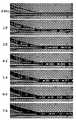
도 3은 본 발명의 또 다른 실시예에서의 상이한 액적 형성 속도로 생성되는 액적의 상이한 크기를 도시하고 있다.
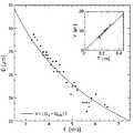
도 4는 본 발명의 또 다른 실시예에서의 빈도의 함수로서의 액적 직경을 도시하고 있다.Non-limiting embodiments of the present invention will now be described by way of example with reference to the accompanying drawings, which are schematic and are not intended to be drawn to scale. In the drawings, each identical or nearly identical component shown is typically represented by a single reference numeral. For the sake of clarity, not all components of all the figures are labeled, and so are all components of each embodiment of the present invention that do not require a person skilled in the art to understand the invention.
1 is a schematic diagram of a droplet-generating system in accordance with one embodiment of the present invention.
Figure 2 illustrates the formation of a substantially monodisperse dual emulsion droplet in yet another embodiment of the present invention.
Figure 3 shows the different sizes of droplets produced at different droplet formation rates in yet another embodiment of the present invention.
Figure 4 shows droplet diameter as a function of frequency in another embodiment of the present invention.
본 발명은 일반적으로 액적을 생성하는 시스템 및 방법에 관한 것이다. 하나의 태양에서, 복수개의 액적이 연속 유체 스트림 내로 유입되어 연속 유체 스트림이 개별 액적을 형성하게 한다. 일부 경우에, 연속 유체 스트림으로부터 형성되는 액적은 실질적으로 단순 분산성일 수 있다. 연속 유체 스트림은 일부 경우에 비교적 높은 선형 유속으로 유동되는 제팅 유체 스트림일 수 있고, 일부 실시예에서, 제팅 유체로부터의 높은 속도의 액적 형성이 그에 의해 성취될 수 있다. 추가로, 본 발명의 일부 태양은 일반적으로 이러한 액적을 형성할 수 있는 미세 유체 장치 등의 장치에 관한 것이다. 예컨대, 한 세트의 실시예에서, 장치는 복수개의 액적이 연속 유체 스트림 내로 유입될 수 있는 접합부를 포함할 수 있고, 선택 사항으로, 장치는 복수개의 액적의 형성 및/또는 연속 유체 스트림의 형성을 유발할 수 있는 추가의 접합부를 포함할 수 있다. 본 발명의 또 다른 태양은 일반적으로 이러한 장치를 제조하는 방법, 이러한 장치를 사용하는 방법, 이러한 장치를 포함하는 키트 등에 관한 것이다.The present invention generally relates to a system and method for generating droplets. In one embodiment, a plurality of droplets are introduced into the continuous fluid stream to cause the continuous fluid stream to form individual droplets. In some cases, the droplets formed from the continuous fluid stream may be substantially simple dispersing. The continuous fluid stream may in some cases be a jetting fluid stream flowing at a relatively high linear velocity and in some embodiments a high velocity droplet formation from the jetting fluid may be achieved thereby. In addition, some aspects of the present invention generally relate to devices such as microfluidic devices capable of forming such droplets. For example, in one set of embodiments, the apparatus may include a junction where a plurality of droplets may be introduced into the continuous fluid stream, and optionally the apparatus may be configured to form a plurality of droplets and / And may include additional joints that may induce. Another aspect of the present invention generally relates to methods of making such devices, methods of using such devices, kits comprising such devices, and the like.
본 발명의 일부 태양은 일반적으로 연속 유체 스트림이 개별 액적을 형성하게 하는 시스템 및 방법에 관한 것이다. 예컨대, 이제부터 도 1에 도시된 예를 참조하면, 제1 유체(21)의 연속 스트림을 수용하는 채널(11)을 포함하는 유체 시스템(10)이 도시되어 있다. 이러한 유체는 후속적으로 분열 또는 분산되어 개별 액적을 형성할 것이고, "분산성 유체"로서도 불릴 수 있다. 일부 실시예에서, 제1 유체(21)는 제1 유체(21)가 제팅 거동(jetting behavior)을 나타내도록 또는 제1 유체가 약 1 초과의 캐필러리 수(Ca: Capillary number) 및/또는 약 1 미만의 웨버 수(We: Weber number)를 갖도록 된 유속으로 채널(11)에 통과될 수 있다. 놀랍게도, 본 발명의 일부 실시예에서, 유체가 분열 또는 분산되어 예컨대 유체가 제팅 거동을 나타내도록 그리고 일부 경우에 형성되는 유체의 개별 액적이 실질적으로 단순 분산성이도록 된 조건 하에서 비교적 높은 유속으로 유체의 별개의 개별 액적을 형성할 수 있다. 예컨대, 이러한 유체 액적은 약 15,000개 액적/초 이상의 속도로 생성될 수 있다(그러나, 다른 경우에, 더 낮은 액적 생성 속도가 또한 가능하다). 대조적으로, 미세 유체 채널 내에서 실질적으로 단순 분산성의 액적을 생성하는 다른 시스템 및 방법이 전형적으로 이러한 조건 하에서 동작될 수 없고, 그에 따라 이러한 높은 유속으로 실질적으로 단순 분산성의 액적을 생성하는 데 사용될 수 없다.Some aspects of the present invention generally relate to systems and methods for causing a continuous fluid stream to form individual droplets. For example, referring now to the example shown in FIG. 1, a
재차 도 1을 참조하면, 접합부(14)에서 채널(11)과 교차되는 채널(17)이 또한 도시되어 있다. 접합부(14) 내로 진입되는 유체는 출구 채널(29)을 통해 접합부로부터 배출될 수 있다. 채널(17)은 제3 유체(25) 내에 수용되는 제2 유체(23)의 액적(27)을 수용할 수 있다. 아래에서 논의되는 것과 같이, 삽입 후에, 제3 유체(25)가 연속 상으로 될 것이고, 한편 제2 유체(25)의 액적(27)이 채널(11)로부터의 제1 유체(21)를 분열 또는 분산시켜 제3 유체(25) 내에 수용된 제1 유체의 개별 액적을 형성하는 데 사용될 것이다. 이와 같이, 제2 유체(23)는 "삽입 유체"로서도 불릴 수 있고, 한편 제3 유체(25)는 "연속 유체"로서도 불릴 수 있다. 일부 실시예에서, 제1 및 제3 유체는 실질적으로 혼합 불가능하고, 일부 경우에, 제1, 제2 및 제3 유체는 각각 실질적으로 상호 혼합 불가능하다. 예컨대, 제1 유체(18)가 플루오로카본 오일 또는 또 다른 오일 등의 소수성 액체일 수 있고, 제3 유체(25)가 물 또는 수성 용액 등의 친수성 액체일 수 있고, 제2 유체(23)가 공기 등의 가스일 수 있고; 또는 제1 유체(18)가 친수성 액체일 수 있고, 제3 유체(25)가 소수성 액체일 수 있고, 제2 유체(23)가 공기 등의 가스일 수 있다. 추가의 예가 아래에서 논의된다.Referring again to FIG. 1, there is also shown a
도 1에 도시된 것과 같이, 채널(17)은 채널(11)로부터의 제1 유체(21) 내로 삽입되는 접합부(14) 내로 제2 유체(23)의 액적 또는 기포를 전달한다. 일부 경우에, 채널(17) 내의 제2 유체(23)의 액적(27)은 실질적으로 단순 분산성이지만, 이들은 다른 경우에 그렇지 않을 수 있다. 채널(11)로부터 진입되는 제1 유체(21) 내로의 액적(27)의 삽입은 제1 유체(21)를 분열 또는 분산시키고, 그에 의해 제1 유체(21)가 분열되게 하여 개별 액적(31)을 형성한다. 출구 채널(29)에서, 제1 유체(21)의 액적(31)이 또한 제2 유체(23)의 액적(27)에 의해 분리될 수 있다. 일부 실시예에서, 액적(31)은 실질적으로 단순 분산성이다.The
언급된 것과 같이, 채널(17) 내에는 제3 유체(25) 내의 제2 유체(23)의 액적(27)이 있다. 일부 경우에, 액적(27)은 실질적으로 단순 분산성이다. 이들 액적은 임의의 적절한 기술을 사용하여 생성될 수 있다. 예컨대, 도 1에 도시된 것과 같이, 제3 유체(25)가 채널(33)을 통해 T자-접합부 내로 진입되고 제2 유체(23)가 채널(34)을 통해 진입되어 (예컨대, 전단력, 계면 장력, 유체 역학적 집속 등으로 인해) 액적(27)을 생성하고 채널(17)을 통해 접합부(12)로부터 배출되는 T자-접합부(12)가 사용된다. (도 1에 도시되지 않은) 또 다른 예로서, 접합부(12)는 유동-집속 접합부일 수 있다.As mentioned, there is a
위의 논의는 액적을 생성하는 데 사용될 수 있는 본 발명의 하나의 실시예의 비-제한 예이다. 그러나, 다른 실시예가 또한 가능하다. 따라서, 더 일반적으로, 본 발명의 다양한 태양은 예컨대 연속 유체 스트림 내로 유체의 액적 또는 기포를 삽입하여 연속 유체 스트림이 개별 액적을 형성하게 함으로써 액적을 생성하는 다양한 시스템 및 방법에 관한 것이다. (여기에서 사용되는 것과 같이, 용어 "유체"는 일반적으로 그 용기의 외형에 따라 유동되는 경향을 갖는 물질 즉 액체, 가스, 점탄성 유체 등을 말하고; 유체가 가스이면, 그 가스의 개별 액적은 "기포"로서도 불릴 수 있다). 일부 경우에, 이러한 액적은 아래에서 논의되는 것과 같이 미세 유체 채널을 수용하는 장치 내에서 생성될 수 있다.The above discussion is a non-limiting example of one embodiment of the present invention that can be used to generate droplets. However, other embodiments are also possible. Thus, more generally, various aspects of the present invention are directed to various systems and methods for creating droplets by inserting droplets or bubbles of fluid into a continuous fluid stream, such that the continuous fluid stream forms individual droplets. (As used herein, the term "fluid" generally refers to materials having a tendency to flow in accordance with the contour of the container, i.e., liquid, gas, viscoelastic fluid, etc., Quot; bubble "). In some cases, these droplets may be generated in an apparatus that accommodates a microfluidic channel as discussed below.
이전에 언급된 것과 같이, 일부 실시예에서, 액적의 생성에서 수반되는 3개(또는 그 이상)의 유체: 즉, 예컨대, 분리되어 개별 액적을 형성하고 여기에서 "분산성 유체"로서도 불릴 수 있는 제1 연속-유동 유체[예컨대, 도 1에서, 유체(21)]; 제1 유체 내로 삽입되어 제1 유체가 액적을 형성하게 하고 여기에서 "삽입 유체"로서도 불릴 수 있는 제2 유체[예컨대, 도 1에서, 유체(23)]의 복수개의 액적; 그리고 제1 유체 내로의 이들의 삽입 전에 제2 유체의 액적을 수용하고 여기에서 "연속 유체"로서도 불릴 수 있는 제3 연속-유동 유체[예컨대, 도 1에서, 유체(25)]가 있을 수 있다. 이러한 제3 유체는 액적-형성 공정의 종료 시에 제1 유체 및 제2 유체가 전형적으로 연속 유체 내에 수용되는 개별 액적으로서 존재하기 때문에 연속 유체로서도 불린다.As previously mentioned, in some embodiments, three (or more) fluids involved in the production of droplets: that is to say, for example, those which form separate droplets separately and may also be referred to herein as " A first continuous-flow fluid (e.g., fluid 21 in Figure 1); A plurality of droplets of a second fluid (e.g., fluid 23 in FIG. 1) that is inserted into a first fluid to cause the first fluid to form a droplet and may also be referred to herein as an "insertion fluid "; There may be a third continuous-flow fluid (e.g., fluid 25 in FIG. 1) that receives a droplet of a second fluid prior to their insertion into the first fluid and may also be referred to herein as a "continuous fluid" . This third fluid is also referred to as a continuous fluid because at the end of the droplet-forming process, the first fluid and the second fluid are typically present as separate droplets that are contained in a continuous fluid.
이와 같이, 설명된 것과 같이, 한 세트의 실시예는 일반적으로 제1 유체의 연속 스트림 내로의 제2 유체의 복수개의 액적(또는 기포)의 삽입에 관한 것이고, 삽입은 제1 유체를 분열 또는 분산시킬 수 있고, 그에 의해 제1 유체의 연속 스트림이 파열되어 개별 액적을 형성하게 한다. 제1 또는 "분산성" 유체는 액체 또는 가스일 수 있다. 일부 실시예에서, 제1 유체의 연속 스트림이 비교적 높은 선형 유속으로 예컨대 제1 유체의 연속 스트림이 제팅 거동을 나타내고 및/또는 약 1 초과의 캐필러리 수 및/또는 약 1 미만의 웨버 수(We)를 갖도록 (예컨대, 접합부 내로) 유입될 수 있다.As such, as set forth, a set of embodiments generally relates to the insertion of a plurality of droplets (or bubbles) of a second fluid into a continuous stream of a first fluid, Thereby causing a continuous stream of the first fluid to rupture to form individual droplets. The first or "dispersible" fluid may be a liquid or a gas. In some embodiments, the continuous stream of the first fluid may have a relatively high linear flow rate, for example, a continuous stream of the first fluid exhibits a jetting behavior and / or a capillary number greater than about 1 and / We (e.g., into the junction).
전형적으로, 유체가 제팅 거동을 나타낼 때에, 유체의 관성력이 표면 장력을 초과하고, 그에 따라, 유체가 "제트"로서 유동된다. 일부 경우에, 제트는 방해받지 않는 상태로 방치되면(즉, 제트와 상호 작용하는 임의의 추가의 유체의 부존재 시에 예컨대 제트 내로의 액적의 임의의 삽입의 부존재 시에) 결국 예컨대 채널 내로의 제팅 유체의 진입부로부터 비교적 멀리 떨어진 지점에서 레일리-플래토 불안정성(Rayleigh-Plateau instability)으로 인해 파열되어 액적을 형성할 수 있지만, 이것이 항상 일어나지는 않는다. 대조적으로, 유체가 "드리핑" 거동을 나타낼 때에, 표면 장력이 지배하고, 이것은 예컨대 채널 내로의 진입 시에 유체가 개별 액적을 형성하게 한다.Typically, when a fluid exhibits a jetting behavior, the inertial force of the fluid exceeds the surface tension, and the fluid then flows as a "jet ". In some cases, the jets are left in an unobstructed state (i.e., in the absence of any additional fluid interacting with the jet, e.g., in the absence of any insertion of a droplet into the jet) Although it may rupture and form droplets due to Rayleigh-Plateau instability at a point relatively far from the fluid's entry, this does not always happen. In contrast, when a fluid exhibits a "dripping" behavior, the surface tension dominates, which allows the fluid to form individual droplets, for example upon entry into the channel.
따라서, 일부 경우에, 제팅 유체가 비교적 높은 선형 유속으로 유동될 수 있다. 예컨대, 채널 내의 제1 유체의 선형 유속은 적어도 약 0.1 ㎛/s, 적어도 약 0.2 ㎛/s, 적어도 약 0.3 ㎛/s, 적어도 약 0.5 ㎛/s, 적어도 약 1 ㎛/s, 적어도 약 3 ㎛/s, 적어도 약 5 ㎛/s, 적어도 약 10 ㎛/s, 적어도 약 30 ㎛/s, 적어도 약 50 ㎛/s, 적어도 약 100 ㎛/s, 적어도 약 300 ㎛/s, 적어도 약 500 ㎛/s, 적어도 약 1 ㎜/s, 적어도 약 3 ㎜/s, 적어도 약 5 ㎜/s, 적어도 약 10 ㎜/s, 적어도 약 30 ㎜/s 또는 적어도 약 50 ㎜/s일 수 있다.Thus, in some cases, the jetting fluid can flow at a relatively high linear velocity. For example, the linear flow rate of the first fluid in the channel may be at least about 0.1 micrometers per second, at least about 0.2 micrometers per second, at least about 0.3 micrometers per second, at least about 0.5 micrometers per second, at least about 1 micrometers per second, at least about 50 占 퐉 / s, at least about 100 占 퐉 / s, at least about 300 占 퐉 / s, at least about 500 占 퐉 / s, at least about 10 占 퐉 / s, at least about 1 mm / s, at least about 3 mm / s, at least about 5 mm / s, at least about 10 mm / s, at least about 30 mm / s, or at least about 50 mm / s.
일부 실시예에서, 제1 유체(분산성 유체)는 유체가 적어도 약 1인 캐필러리 수(Ca)를 나타내도록 및/또는 웨버 수(We)가 약 1 미만이도록 된 조건 하에서 채널 내에서 유동될 수 있다. 예컨대, 제1 유체는 미세 유체 채널 내로 진입될 때에 또는 제2 유체의 액적이 제1 유체 내로 삽입되는 위치에서 이들 등의 조건 하에서 유동될 수 있다. 일반적으로, 캐필러리 수는 채널을 통해 유동되는 유체의 점성력 대 표면 장력의 상대 효과를 표현하고, 한편 웨버 수(We)는 그 표면 장력에 비교되는 유체의 관성력을 표현한다. 캐필러리 수 및/또는 웨버 수(We)는 일부 실시예에서 예컨대 채널 내의 유체의 속도 및/또는 채널의 형상 또는 크기 예컨대 그 평균 단면 치수를 제어함으로써 제어될 수 있다.In some embodiments, the first fluid (dispersible fluid) is a flow of fluid in the channel under conditions such that the fluid exhibits a capillary number (Ca) of at least about 1 and / or the number of weber (We) . For example, the first fluid may flow under the conditions such as when entering the microfluidic channel, or where the droplets of the second fluid are inserted into the first fluid. In general, the capillary number expresses the relative effect of the viscous force of the fluid flowing through the channel to the surface tension, while the Weber number (We) expresses the inertial force of the fluid compared to its surface tension. The capillary number and / or the Weber number (We) may be controlled in some embodiments, for example, by controlling the velocity of the fluid in the channel and / or the shape or size of the channel, e.g., the average cross-sectional dimension thereof.
캐필러리 수(Ca)는 다음과 같이 정의될 수 있다:The capillary number (Ca) can be defined as:

여기에서 μ(뮤)는 유체의 동적 점도이고, V는 유체의 속도(또는 선형 유속)이고, γ(감마)는 채널 내의 유체의 표면 또는 계면 장력이다. 일부 실시예에서, 제1 유체의 Ca는 적어도 약 3, 적어도 약 10, 적어도 약 30, 적어도 약 100, 적어도 약 300 또는 적어도 약 1000일 수 있다.Where mu (mu) is the kinematic viscosity of the fluid, V is the velocity of the fluid (or linear velocity), and gamma is the surface or interface tension of the fluid in the channel. In some embodiments, the Ca of the first fluid may be at least about 3, at least about 10, at least about 30, at least about 100, at least about 300, or at least about 1000.
언급된 것과 같이, 웨버 수(We)는 (유체를 일관되게 유지하는) 관성 효과와 (유체가 액적을 형성하는 경향을 갖게 하는) 표면 장력 효과 사이의 균형 또는 비율로서 간주될 수 있다. 웨버 수는 종종 관성 효과에 의해 제산된 표면 장력 효과의 무차원 비율로서 표현되고, 즉 웨버 수가 1보다 클 때에, 표면 장력 효과가 지배하고, 웨버 수가 1보다 작을 때에, 관성 효과가 지배한다. 이와 같이, "웨버 수"는 다음과 같이 정의될 수 있다:As mentioned, the Weber number, We, can be regarded as a balance or ratio between the inertial effect (which keeps the fluid consistent) and the surface tension effect (which makes the fluid tend to form droplets). The Weber number is often expressed as a dimensionless ratio of the surface tension effect divided by the inertia effect, i.e., when the number of Weber is greater than 1, the surface tension effect dominates, and when the Weber number is less than 1, the inertia effect dominates. As such, the "number of Weber" can be defined as:

여기에서 ρ(로)는 유체의 밀도이고, v는 그 속도이고, l은 그 특성 길이(전형적으로, 액적 직경)이고, σ(시그마)는 표면 장력이다. 일부 실시예에서, We는 약 0.3 미만, 약 0.1 미만, 약 0.03 미만, 약 0.01 미만, 약 0.003 미만 또는 약 0.001 미만일 수 있고, 즉 관성 효과가 지배하도록 되어 있을 수 있다.Where ρ is the density of the fluid, v is the velocity, l is its characteristic length (typically the droplet diameter), and sigma (sigma) is the surface tension. In some embodiments, We may be less than about 0.3, less than about 0.1, less than about 0.03, less than about 0.01, less than about 0.003, or less than about 0.001, i.e. the inertial effect may be dominated.
유동 중에 높은 캐필러리 수 및/또는 낮은 웨버 수를 나타내는 제팅 유체 또는 유체들의 사용은 제1 유체의 액적이 일부 실시예에 따라 매우 급속하게 생성되게 할 수 있다. 일부 경우에, 액적 생성 속도는 다른 기술의 액적 생성 속도를 초과할 수 있다(그러나, 다른 경우에, 더 낮은 액적 생성 속도가 사용될 수 있다). 예컨대, (예컨대, 제1 유체의 제팅 스트림으로부터의) 액적의 생성 속도는 적어도 약 5,000개 액적/초, 적어도 약 10,000개 액적/초, 적어도 약 15,000개 액적/초, 적어도 약 17,000개 액적/초, 적어도 약 19,000개 액적/초, 적어도 약 20,000개 액적/초, 적어도 약 25,000개 액적/초, 적어도 약 30,000개 액적/초, 적어도 약 50,000개 액적/초, 적어도 약 60,000개 액적/초, 적어도 약 70,000개 액적/초 또는 적어도 약 100,000개 액적/초일 수 있다. 일부 실시예에서, 제2 유체의 액적이 연속 유동 제1 유체 스트림 내로 삽입되어 제1 유체 스트림의 선형 유동 속도를 실질적으로 변화시키지 않으면서 제1 유체 스트림이 개별 액적을 형성하게 할 수 있다. 추가로, 일부 실시예에서, 선형 유동 속도는 그 초기 유속에 대해 약 25% 이하, 약 15% 이하, 약 10% 이하, 약 5% 이하 등만큼 변화될 수 있다.The use of jetting fluids or fluids exhibiting a high capillary number and / or a low webber number in the flow can cause droplets of the first fluid to be generated very rapidly, depending on some embodiments. In some cases, the droplet generation rate may exceed the droplet generation rate of other techniques (but in other cases, a lower droplet generation rate may be used). For example, the rate of formation of droplets (e.g., from the jetting stream of the first fluid) may be at least about 5,000 droplets / second, at least about 10,000 droplets / second, at least about 15,000 droplets / second, at least about 17,000 droplets / At least about 20,000 droplets per second, at least about 25,000 droplets per second, at least about 30,000 droplets per second, at least about 50,000 droplets per second, at least about 60,000 droplets per second, at least about 19,000 droplets per second, at least about 20,000 droplets per second, About 70,000 droplets / second or at least about 100,000 droplets / second. In some embodiments, a droplet of the second fluid may be inserted into the continuous-flow first fluid stream to cause the first fluid stream to form an individual droplet without substantially changing the linear flow rate of the first fluid stream. Additionally, in some embodiments, the linear flow velocity may be varied by no more than about 25%, no more than about 15%, no more than about 10%, no more than about 5%, etc., relative to its initial flow rate.
여기에서 설명된 것들 등의 기술을 사용하여 생성되는 제1 유체의 액적은 일부 실시예에서 일부 경우에 약 1 ㎜ 미만, 약 500 ㎛ 미만, 약 300 ㎛ 미만, 약 200 ㎛ 미만, 약 100 ㎛ 미만, 약 75 ㎛ 미만, 약 50 ㎛ 미만, 약 30 ㎛ 미만, 약 25 ㎛ 미만, 약 10 ㎛ 미만, 약 5 ㎛ 미만, 약 3 ㎛ 미만 또는 약 1 ㎛ 미만의 평균 치수 또는 직경을 가질 수 있다. 평균 직경은 또한 일부 경우에 적어도 약 1 ㎛, 적어도 약 2 ㎛, 적어도 약 3 ㎛, 적어도 약 5 ㎛, 적어도 약 10 ㎛, 적어도 약 15 ㎛ 또는 적어도 약 20 ㎛일 수 있다. 액적은 구체 또는 비-구체일 수 있다. 액적의 평균 직경은 액적이 비-구체이면 비-구체 액적과 동일한 체적을 갖는 완벽한 구체의 직경으로서 간주될 수 있다.The droplets of the first fluid produced using techniques such as those described herein may in some embodiments be less than about 1 mm in some cases, less than about 500 microns, less than about 300 microns, less than about 200 microns, less than about 100 microns , Less than about 75 占 퐉, less than about 50 占 퐉, less than about 30 占 퐉, less than about 25 占 퐉, less than about 10 占 퐉, less than about 5 占 퐉, less than about 3 占 퐉, or less than about 1 占 퐉. The average diameter may also be at least about 1 占 퐉, at least about 2 占 퐉, at least about 3 占 퐉, at least about 5 占 퐉, at least about 10 占 퐉, at least about 15 占 퐉, or at least about 20 占 퐉 in some cases. The droplets may be spherical or non-spherical. The average diameter of the droplets can be regarded as the diameter of the perfect spheres having the same volume as the non-spherical droplets if the droplet is non-spherical.
일부 경우에, 제1 유체의 액적이 실질적으로 단순 분산성일 수 있거나, 액적이 균질한 직경 분포를 가질 수 있고, 예컨대 액적은 액적의 약 10% 이하, 약 5% 이하, 약 3% 이하, 약 2% 이하 또는 약 1% 이하가 복수개의 액적의 전체 평균 직경의 약 90% 미만(또는 약 95% 미만, 약 97% 미만 또는 약 99% 미만) 및/또는 약 110% 초과(또는 약 101% 초과, 약 103% 초과 또는 약 105% 초과)의 직경을 갖도록 된 직경 분포를 가질 수 있다. 일부 실시예에서, 복수개의 액적은 액적의 단면 직경의 변동 계수가 약 10% 미만, 약 5% 미만, 약 2% 미만, 약 1% 내지 약 10%, 약 1% 내지 약 5% 또는 약 1% 내지 약 2%이도록 된 전체 평균 직경 및 직경 분포를 갖는다. 변동 계수는 평균에 의해 제산된 표준 편차로서 정의될 수 있고, 당업자에 의해 결정될 수 있다.In some cases, the droplet of the first fluid may be substantially simple dispersing, or the droplet may have a homogeneous diameter distribution, for example, about 10% or less, about 5% or less, about 3% (Or less than about 95%, less than about 97%, or less than about 99%) and / or greater than about 110% (or less than about 101%) of the total average diameter of the plurality of droplets, , Greater than about 103%, or greater than about 105%). In some embodiments, the coefficient of variation of the cross-sectional diameter of a plurality of droplet droplets is less than about 10%, less than about 5%, less than about 2%, from about 1% to about 10%, from about 1% to about 5% % ≪ / RTI > to about 2%. The coefficient of variation can be defined as the standard deviation divided by the mean, and can be determined by one skilled in the art.
한 세트의 실시예에서, 제1(또는 분산성) 유체는 그 자체가 1개 초과의 유체를 포함할 수 있다. 예컨대, 제1 유체는 그 내에 2개, 3개, 4개 또는 그 이상의 유체를 포함할 수 있다. 제2 유체의 액적의 삽입 시에, 위에서 논의된 것과 같이, 이들 유체의 일부 또는 모두가 제팅 거동을 나타낼 수 있고, 및/또는 제1 유체가 약 1 초과의 캐필러리 수 및/또는 약 1 미만의 웨버 수(We)를 나타낼 수 있다. 한 세트의 실시예에서, 이들 유체 중 2개 이상이 예컨대 하나의 유체가 또 다른 유체에 의해 부분적으로 또는 완전히 포위되는 "코어/외피" 배열로 존재할 수 있다. 다른 배열 예컨대 유체가 나란히 위치되는 배열이 또한 다른 실시예에서 가능하다. 제2 유체의 액적의 삽입은 2개 이상의 유체가 이들 유체의 일부 또는 모두를 수용하는 개별 액적을 형성하게 할 수 있다. 일부 경우에, 유체는 예컨대 코어/외피 배열로 액적 내에 별개 유체로서 남아 있을 수 있고, 그에 의해 외피 유체에 의해 포위되는 코어 유체를 포함하는 이중 에멀션을 형성하고, 외피 유체는 결국 제3 유체 내에 수용된다. 다른 배열 예컨대 3중 에멀션 또는 다른 더 높은 수준의 다중 에멀션이 또한 본 발명의 다른 실시예에서 가능하다. 그러나, 또 다른 실시예에서, 액적 내의 유체들의 일부 또는 모두가 함께 혼합 및/또는 반응될 수 있다.In one set of embodiments, the first (or dispersible) fluid may itself comprise more than one fluid. For example, the first fluid may include two, three, four, or more fluids therein. Upon insertion of the droplets of the second fluid, as discussed above, some or all of these fluids may exhibit jetting behavior and / or the first fluid may have a capillary number greater than about 1 and / (We) < / RTI > In one set of embodiments, two or more of these fluids may be present in a "core / sheath" arrangement in which, for example, one fluid is partially or completely surrounded by another fluid. Arrangements in which other arrangements such as fluid are located side by side are also possible in other embodiments. The insertion of the droplets of the second fluid may cause the two or more fluids to form individual droplets that contain some or all of these fluids. In some cases, the fluid may remain in the droplet as a separate fluid, for example in a core / shell arrangement, thereby forming a dual emulsion comprising a core fluid surrounded by an envelope fluid, do. Other arrangements such as triple emulsions or other higher levels of multiple emulsions are also possible in other embodiments of the present invention. However, in another embodiment, some or all of the fluids in the droplet may be mixed and / or reacted together.
언급된 것과 같이, 제2 또는 "삽입" 유체가 연속-유동 제1 유체 스트림 내로 삽입되어 제1 유체 스트림이 개별 액적을 형성하게 할 수 있다. 제2 유체는 복수개의 액적 또는 기포로서 제1 유체 스트림 내로 삽입될 수 있고, 액체 및/또는 가스를 포함할 수 있다. 제2 유체의 액적이 또한 일부 실시예에서 실질적으로 단순 분산성일 수 있거나, 제2 유체의 액적이 균질한 직경 분포를 가질 수 있다. 제2 유체는 본 발명의 일부 실시예에서 제1 유체와 실질적으로 혼합 불가능할 수 있지만, 다른 실시예에서 제2 유체 및 제1 유체는 실질적으로 혼합 불가능하지 않다. 예컨대, 일부 조건 하에서, 제1 유체 스트림이 제2 유체의 액적의 삽입 시에 제1 유체의 개별 액적을 형성하도록 분산되는 속도는 제1 유체의 개별 액적이 형성되기 전에 제1 및 제2 유체가 실질적으로 혼합되는 시간을 갖지 못할 정도로 충분히 빠르다.As mentioned, a second or "insert" fluid may be inserted into the continuous-flow first fluid stream to allow the first fluid stream to form individual droplets. The second fluid may be inserted into the first fluid stream as a plurality of droplets or bubbles, and may include liquid and / or gas. The droplets of the second fluid may also be substantially monodisperse in some embodiments, or the droplets of the second fluid may have a homogeneous diameter distribution. The second fluid may be substantially non-mixable with the first fluid in some embodiments of the present invention, but in other embodiments the second fluid and the first fluid are substantially non-mixable. For example, under some conditions, the rate at which the first fluid stream is dispersed to form a separate droplet of the first fluid upon insertion of the second fluid is such that the velocity of the first and second fluids It is fast enough to not have a substantial mixing time.
논의된 것과 같이, 제2 유체의 액적이 일부 실시예에서 실질적으로 단순 분산성일 수 있거나, 제2 유체의 액적이 균질한 직경 분포를 가질 수 있다. 예컨대, 제2 유체의 액적은 액적의 약 10% 이하, 약 5% 이하, 약 3% 이하, 약 2% 이하 또는 약 1% 이하가 제2 유체의 복수개의 액적의 전체 평균 직경의 약 90% 미만(또는 약 95% 미만, 약 97% 미만 또는 약 99% 미만) 및/또는 약 110% 초과(또는 약 101% 초과, 약 103% 초과 또는 약 105% 초과)의 직경을 갖도록 된 직경 분포를 가질 수 있다. 일부 실시예에서, 제2 유체의 복수개의 액적은 액적의 단면 직경의 변동 계수가 약 10% 미만, 약 5% 미만, 약 2% 미만, 약 1% 내지 약 10%, 약 1% 내지 약 5% 또는 약 1% 내지 약 2%이도록 된 전체 평균 직경 및 직경 분포를 갖는다.As discussed, the droplet of the second fluid may be substantially simple dispersibility in some embodiments, or the droplet of the second fluid may have a homogeneous diameter distribution. For example, about 10% or less, about 5% or less, about 3% or less, about 2% or less, or about 1% or less of the droplet size of the droplet of the second fluid is about 90% (Or less than about 95%, less than about 97%, or less than about 99%) and / or greater than about 110% (or greater than about 101%, greater than about 103%, or greater than about 105% Lt; / RTI > In some embodiments, the coefficient of variation of the cross-sectional diameter of the plurality of droplet droplets of the second fluid is less than about 10%, less than about 5%, less than about 2%, about 1% to about 10%, about 1% %, Or from about 1% to about 2%.
일부 경우에, 제2 유체의 액적은 일부 경우에 약 1 ㎜ 미만, 약 500 ㎛ 미만, 약 300 ㎛ 미만, 약 200 ㎛ 미만, 약 100 ㎛ 미만, 약 75 ㎛ 미만, 약 50 ㎛ 미만, 약 30 ㎛ 미만, 약 25 ㎛ 미만, 약 10 ㎛ 미만, 약 5 ㎛ 미만, 약 3 ㎛ 미만 또는 약 1 ㎛ 미만의 평균 치수 또는 직경을 가질 수 있다. 평균 직경은 또한 일부 경우에 적어도 약 1 ㎛, 적어도 약 2 ㎛, 적어도 약 3 ㎛, 적어도 약 5 ㎛, 적어도 약 10 ㎛, 적어도 약 15 ㎛ 또는 적어도 약 20 ㎛일 수 있다. 액적은 구체 또는 비-구체일 수 있다. 일부 실시예에서, 제1 유체의 액적의 생성 속도 및/또는 크기 분포는 적어도 부분적으로 제2 유체의 액적의 생성 속도 및/또는 크기 분포에 의해 제어될 수 있다.In some cases, the droplets of the second fluid may be less than about 1 mm, less than about 500 탆, less than about 300 탆, less than about 200 탆, less than about 100 탆, less than about 75 탆, less than about 50 탆, Less than about 25 [mu] m, less than about 10 [mu] m, less than about 5 [mu] m, less than about 3 [mu] m or less than about 1 [mu] m. The average diameter may also be at least about 1 占 퐉, at least about 2 占 퐉, at least about 3 占 퐉, at least about 5 占 퐉, at least about 10 占 퐉, at least about 15 占 퐉, or at least about 20 占 퐉 in some cases. The droplets may be spherical or non-spherical. In some embodiments, the rate of formation and / or size distribution of the droplets of the first fluid may be controlled at least in part by the rate of formation and / or size distribution of the droplets of the second fluid.
일부 실시예에서, 제2 유체의 액적은 비교적 일정한 속도로 그리고 일부 경우에 비교적 높은 속도로 제1 유체 내로 삽입될 수 있다. 예컨대, 액적은 적어도 약 5,000개 액적/초, 적어도 약 10,000개 액적/초, 적어도 약 15,000개 액적/초, 적어도 약 20,000개 액적/초, 적어도 약 30,000개 액적/초, 적어도 약 50,000개 액적/초, 적어도 약 70,000개 액적/초 또는 적어도 약 100,000개 액적/초의 속도로 삽입될 수 있다. 논의된 것과 같이, 제1 유체의 연속-유동 스트림 내로의 제2 유체의 액적의 삽입 속도는 적어도 부분적으로 연속-유동 스트림으로부터의 제1 유체의 액적의 생성 속도를 제어할 수 있다.In some embodiments, the droplet of the second fluid may be inserted into the first fluid at a relatively constant rate and in some cases at a relatively high rate. At least about 10,000 droplets per second, at least about 15,000 droplets per second, at least about 20,000 droplets per second, at least about 30,000 droplets per second, at least about 50,000 droplets per second, at least about 5,000 droplets per second, at least about 10,000 droplets per second, Sec, at least about 70,000 droplets / sec, or at least about 100,000 droplets / sec. As discussed, the rate of insertion of the droplet of the second fluid into the continuous-flow stream of the first fluid can at least partially control the rate of formation of the droplet of the first fluid from the continuous-flow stream.
일부 실시예에서, 제2 유체의 액적 또는 기포는 또 다른 제3 유체 내에 수용될 수 있고, 제3 유체는 결국 제1 유체의 액적 및/또는 제2 유체의 액적을 수용하는 연속 유체를 형성한다. 연속 유체는 아래에서 논의되는 것과 같이 본 발명의 일부 실시예에서 제1 유체 및 제2 유체의 한쪽 또는 양쪽 모두와 실질적으로 혼합 불가능할 수 있다. 그러나, 다른 실시예에서, 이들 유체는 모두가 실질적으로 상호 혼합 불가능할 필요는 없다. 예컨대, 위에서 언급된 것과 같이, 제1 유체가 제1 유체의 연속-유동 스트림 내로의 제2 유체의 액적의 삽입 시에 분산 또는 분열되어 개별 액적을 형성하는 속도는 제1 유체의 개별 액적이 형성되기 전에 제1, 제2 및 제3 유체가 실질적으로 혼합되는 시간을 갖지 못할 정도로 충분히 빠를 수 있다.In some embodiments, the droplets or bubbles of the second fluid may be contained in another third fluid, and the third fluid eventually forms a continuous fluid that contains droplets of the first fluid and / or droplets of the second fluid . The continuous fluid may be substantially non-mixable with either or both of the first fluid and the second fluid in some embodiments of the present invention, as discussed below. However, in other embodiments, all of these fluids need not be substantially non-intermixable. For example, as noted above, the rate at which a first fluid is dispersed or divided to form individual droplets upon insertion of a droplet of a second fluid into the continuous-flow stream of a first fluid is determined by the formation of individual droplets of the first fluid The first, second, and third fluids may not have time to substantially mix before they are mixed.
일부 실시예에서, 제3 유체는 비교적 높은 선형 유속으로 유동될 수 있다. 예컨대, 제3 유체는 제2 유체의 액적이 제1 유체 내로 삽입되는 지점에서 제팅 거동을 나타낼 수 있다. 일부 실시예에서, 채널 내의 제3 유체의 선형 유속은 적어도 약 0.1 ㎛/s, 적어도 약 0.2 ㎛/s, 적어도 약 0.3 ㎛/s, 적어도 약 0.5 ㎛/s, 적어도 약 1 ㎛/s, 적어도 약 3 ㎛/s, 적어도 약 5 ㎛/s, 적어도 약 10 ㎛/s, 적어도 약 30 ㎛/s, 적어도 약 50 ㎛/s, 적어도 약 100 ㎛/s, 적어도 약 300 ㎛/s, 적어도 약 500 ㎛/s, 적어도 약 1 ㎜/s, 적어도 약 3 ㎜/s, 적어도 약 5 ㎜/s, 적어도 약 10 ㎜/s, 적어도 약 30 ㎜/s 또는 적어도 약 50 ㎜/s일 수 있다. 그러나, 다른 실시예에서, 제3 유체는 이러한 높은 유속으로 유동될 필요는 없고, 위에서 설명된 수치들 중 어떤 수치보다 느릴 수 있다. 추가로, 제2 유체의 액적이 제1 유체 내로 삽입되는 지점에서의 제3 유체 및 제1 유체의 선형 유속은 동일 또는 상이할 수 있다.In some embodiments, the third fluid may flow at a relatively high linear flow rate. For example, the third fluid may exhibit a jetting behavior at a point where a droplet of the second fluid is inserted into the first fluid. In some embodiments, the linear flow rate of the third fluid in the channel is at least about 0.1 micrometers per second, at least about 0.2 micrometers per second, at least about 0.3 micrometers per second, at least about 0.5 micrometers per second, at least about 1 micrometers per second, At least about 10 탆 / s, at least about 30 탆 / s, at least about 50 탆 / s, at least about 100 탆 / s, at least about 300 탆 / At least about 1 mm / s, at least about 3 mm / s, at least about 5 mm / s, at least about 10 mm / s, at least about 30 mm / s, or at least about 50 mm / s. However, in other embodiments, the third fluid need not flow at such a high flow rate, and may be slower than any of the values described above. Additionally, the linear flow rates of the third fluid and the first fluid at the point where the droplets of the second fluid are inserted into the first fluid may be the same or different.
언급된 것과 같이, 제1 유체, 제2 유체 및 제3 유체는 본 발명의 일부 실시예에서 실질적으로 상호 혼합 불가능할 수 있다. 3개의 실질적으로 상호 혼합 불가능한 유체를 포함하는 시스템의 하나의 비-제한 예는 유체들 중 2개가 액체(예컨대, 실질적으로 혼합 불가능한 유체)이고 한편 제3 유체가 가스인 시스템이다. 예컨대, 제2 유체는 가스로서 존재할 수 있고, 한편 제1 및 제3 유체는 각각 액체일 수 있다.As mentioned, the first fluid, the second fluid, and the third fluid may be substantially non-intermixable in some embodiments of the present invention. One non-limiting example of a system comprising three substantially non-intermixable fluids is a system in which two of the fluids are liquid (e.g., substantially non-mixable fluids) while the third fluid is a gas. For example, the second fluid may be present as a gas while the first and third fluids may each be liquid.
일부 실시예에서, 제1 유체는 친수성 또는 수성일 수 있고, 한편 제2 유체는 소수성 또는 "오일"일 수 있고, 그 반대일 수 있다. 전형적으로, "친수성" 유체는 순수한 물과 혼합 가능한 유체이고, 한편 "소수성" 유체는 순수한 물과 혼합 가능하지 않은 유체이다. 용어 "오일"은 여기에서 사용되는 것과 같이 단순히 소수성이고 물 내에 혼합 가능하지 않은 유체를 말한다는 것이 주목되어야 한다. 이와 같이, 오일은 일부 실시예에서 탄화수소일 수 있지만, 다른 실시예에서, 오일은 다른 소수성 유체(예컨대, 옥탄올)이거나 이것을 포함할 수 있다. 친수성 또는 수성 유체가 순수한 물일 필요는 없다는 것이 또한 주목되어야 한다. 예컨대, 친수성 유체는 수성 용액 예컨대 완충 용액, 용해된 염을 함유하는 용액 등일 수 있다. 친수성 유체는 또한 예컨대 물 대신에 또는 이것에 추가하여 예컨대 물 내에 혼합 가능한 에탄올 또는 다른 액체이거나 이것을 포함할 수 있다.In some embodiments, the first fluid may be hydrophilic or aqueous, while the second fluid may be hydrophobic or "oil ", or vice versa. Typically, a "hydrophilic" fluid is a fluid that is compatible with pure water, while a "hydrophobic" fluid is a fluid that is not miscible with pure water. It should be noted that the term "oil" refers to a fluid which is simply hydrophobic as used herein and which is not miscible in water. As such, the oil may be a hydrocarbon in some embodiments, but in other embodiments the oil may or may not be another hydrophobic fluid (e.g., octanol). It should also be noted that the hydrophilic or aqueous fluid need not be pure water. For example, the hydrophilic fluid may be an aqueous solution, such as a buffered solution, a solution containing a dissolved salt, and the like. The hydrophilic fluid can also be or include, for example, ethanol or other liquid that can be mixed in water instead of or in addition to water, for example.
그러나, 제1 유체, 제2 유체 및 제3 유체는 1개가 가스이고 다른 2개가 액체인 시스템에만 제한되지 않는다. 다른 유체 배열 예컨대 모든 3개의 유체가 액체인 유체 배열이 또한 가능하다. 비-제한 예로서, 또 다른 시스템의 3개의 실질적으로 상호 혼합 불가능한 액체는 실리콘 오일, 미네랄 오일 및 수성 용액(즉, 물 또는 그 내에 용해 및/또는 현탁되는 1개 이상의 다른 화학종을 함유하는 물)이다. 시스템의 또 다른 예는 실리콘 오일, 플루오로카본 오일 및 수성 용액이다. 시스템의 또 다른 예는 탄화수소 오일(헥사데칸), 플루오로카본 오일 및 수성 용액이다. 적절한 플루오로카본의 비-제한 예는 HFE7500, 옥타데카플루오로데카하이드로나프탈렌:However, the first fluid, the second fluid and the third fluid are not limited to a system in which one is gas and the other two are liquids. Other fluid arrangements, such as a fluid arrangement in which all three fluids are liquids, are also possible. By way of non-limiting example, the three substantially non-intermixable liquids of another system may be selected from the group consisting of silicone oil, mineral oil and aqueous solution (i.e., water containing water or one or more other chemical species dissolved and / )to be. Another example of a system is silicone oil, fluorocarbon oil and aqueous solution. Other examples of systems are hydrocarbon oils (hexadecane), fluorocarbon oil, and aqueous solutions. Non-limiting examples of suitable fluorocarbons include HFE 7500, octadecafluorodecahydronaphthalene:

또는 1-(1,2,2,3,3,4,4,5,5,6,6-언데카플루오로시클로헥실)에탄올:Or 1- (1,2,2,3,3,4,4,5,5,6,6-undecafluorocyclohexyl) ethanol:

을 포함한다..
일부 경우에, 제1 유체의 개별 액적이 제1 유체의 연속-유동 스트림 내로의 제2 유체의 액적의 삽입에 의해 제3 유체 내에 형성된 후에, 제2 유체의 일부 또는 모두가 제3 유체로부터 제거 또는 분리될 수 있다. 제2 유체가 액적 또는 기포로서 존재할 수 있거나, 일부 경우에, 제2 유체의 일부 또는 모두가 합체될 수 있다. 제2 유체를 제거하는 데 사용될 수 있는 기술의 예는 여과, 침전 또는 부력을 포함하지만 이들에 제한되지 않는다. 하나의 예로서, 제3 유체가 원심력에 노출되어 제2 유체의 적어도 일부의 분리를 유발할 수 있다. 또 다른 예로서, 밀도 차이가 예컨대 유체가 실질적으로 방해받지 않는 상태로 남아 있게 하면 (예컨대, 제3 유체에 대해 상승 또는 하강됨으로써) 제2 유체의 분리가 일어나게 할 수 있다. 예컨대, 제2 유체가 가스이면, 밀도 차이 또는 부력이 제2 유체의 적어도 일부가 상승되게 하거나 심지어 제3 유체로부터 배출되게 할 수 있다. 또 다른 예로서, 유체 역학적 선별 기술이 제3 유체로부터 제2 유체의 적어도 일부를 제거 또는 분리하는 데 사용될 수 있다. 일부 경우에, 제1 유체 및/또는 제3 유체에 대한 제2 유체의 유체 역학적 성질의 차이가 분리가 일어나게 하는 데 사용될 수 있다. 예컨대, 점도, 밀도, 체적, 표면적, 직경 등의 차이가 예컨대 유동 조건 하에서 분리가 일어나게 하는 데 사용될 수 있다. 이와 같이, 예컨대, 층류 하에서, 하나의 유체의 액적이 또 다른 유체의 액적보다 빠르게 또는 느리게 유동될 수 있고, 이것이 그에 의해 액적을 분리하는 데 사용될 수 있다. 이러한 선별 기술의 추가의 비-제한 예가 참조로 여기에 각각 합체되어 있는 링크(Link) 등에 의해 "유체 화학종의 전자 제어(Electronic Control of Fluidic Species)"의 발명의 명칭으로 2004년 8월 27일자로 출원되어 2005년 3월 10일자로 제WO 2005/021151호로서 공개된 국제 특허 출원 제PCT/US2004/027912호에서 찾아볼 수 있다.In some cases, after a separate droplet of the first fluid is formed in the third fluid by insertion of a droplet of the second fluid into the continuous-flow stream of the first fluid, some or all of the second fluid is removed from the third fluid Or separated. The second fluid may be present as a droplet or bubble, or, in some cases, some or all of the second fluid may be combined. Examples of techniques that can be used to remove the second fluid include, but are not limited to filtration, sedimentation or buoyancy. As an example, the third fluid may be exposed to centrifugal forces to cause separation of at least a portion of the second fluid. As another example, the density difference can cause the separation of the second fluid to occur, for example, if the fluid remains substantially unobstructed (e.g., by being raised or lowered relative to the third fluid). For example, if the second fluid is a gas, a density difference or buoyancy may cause at least a portion of the second fluid to rise or even to exit from the third fluid. As another example, a hydrodynamic sorting technique may be used to remove or separate at least a portion of the second fluid from the third fluid. In some cases, differences in the hydrodynamic properties of the second fluid relative to the first fluid and / or the third fluid can be used to cause separation. For example, differences in viscosity, density, volume, surface area, diameter, etc. can be used to effect separation, for example under flow conditions. Thus, for example, under laminar flow, a droplet of one fluid can flow faster or slower than another droplet, which can be used thereby to separate the droplet. An additional non-limiting example of such a sorting technique is described in U.S. Patent Application No. 10 / 548,503, entitled " Electronic Control of Fluidic Species " And International Patent Application No. PCT / US2004 / 027912, published as WO 2005/021151 on Mar. 10, 2005, which is hereby incorporated by reference in its entirety.
본 발명의 다른 태양은 일반적으로 예컨대 이전에 논의된 것과 같이 연속 유체 스트림이 개별 액적을 형성하게 하는 미세 유체 시스템 및 방법에 관한 것이다. 예컨대, 한 세트의 실시예에서, 미세 유체 장치는 연속 유체 스트림 내로 유체의 액체 또는 기포를 삽입하여 연속 유체 스트림이 개별 액적을 형성하게 함으로써 개별 액적을 생성하는 데 사용될 수 있다. 일부 경우에, 미세 유체 장치는 채널들의 접합부 예컨대 제1 입구 미세 유체 채널, 제2 입구 미세 유체 채널 및 출구 미세 유체 채널의 접합부를 포함할 수 있다. 제1 미세 유체 채널은 (연속성일 수 있고, 일부 경우에 제팅 거동을 나타낼 수 있는) 제1 유체를 유입시킬 수 있고, 제2 미세 유체 채널은 (예컨대, 연속 제3 유체 내에 수용되는 복수개의 액적으로서) 제2 유체를 유입시킬 수 있다. 접합부에서, 제2 유체의 액적은 제1 유체의 연속 스트림 내로 삽입되어 제1 유체의 유체 스트림이 개별 액적을 형성하게 할 수 있다. 제1 및 제2 미세 유체 채널로부터의 유체는 출구 미세 유체 채널을 통해 접합부로부터 배출될 수 있다.Other aspects of the present invention generally relate to microfluidic systems and methods that allow a continuous fluid stream to form individual droplets, e.g., as discussed previously. For example, in one set of embodiments, a microfluidic device may be used to insert a liquid or bubble of fluid into a continuous fluid stream to cause the continuous fluid stream to form individual droplets. In some cases, the microfluidic device may include a junction of channels, such as a junction of a first inlet microfluidic channel, a second inlet microfluidic channel, and an outlet microfluidic channel. The first microfluidic channel may introduce a first fluid (which may be continuous and may exhibit a jetting behavior in some cases), and the second microfluidic channel may introduce a plurality of droplets (e.g., The second fluid can be introduced. At the junction, a droplet of the second fluid may be inserted into the continuous stream of the first fluid so that the fluid stream of the first fluid forms a separate droplet. The fluid from the first and second microfluidic channels may be discharged from the junction through the exit microfluidic channel.
일부 경우에, 제1 채널은 어떤 각도로 접합부에서 제2 채널과 교차될 수 있다. 이러한 각도는 예컨대 제1 유체의 유동을 실질적으로 분열시키지 않으면서 제2 유체의 액적의 삽입을 가능케 하는 데 유용할 수 있다. 이와 같이, 예컨대, 삽입은 제1 유체 스트림의 선형 유속이 실질적으로 변화되지 않도록 또는 제1 유체 스트림의 선형 유속이 약 25% 이하, 약 15% 이하, 약 10% 이하, 약 5% 이하 등만큼 변화되지 않도록 일어날 수 있다. 한 세트의 실시예에서, 접합부에서의 제1 채널과 제2 채널 사이의 각도는 약 60˚ 미만, 약 45˚ 미만, 약 40˚ 미만, 약 35˚ 미만, 약 30˚ 미만, 약 25˚ 미만 또는 약 20˚ 미만이다. 이러한 구성의 비-제한 예가 도 1에 도시되어 있다.In some cases, the first channel may intersect the second channel at the junction at an angle. Such an angle may be useful, for example, to enable insertion of a droplet of a second fluid without substantially disrupting the flow of the first fluid. Thus, for example, the insertion may be such that the linear flow rate of the first fluid stream is substantially unchanged or that the linear flow velocity of the first fluid stream is less than or equal to about 25%, less than or equal to about 15%, less than or equal to about 10% It can happen to be unchanged. In one set of embodiments, the angle between the first channel and the second channel at the junction is less than about 60 degrees, less than about 45 degrees, less than about 40 degrees, less than about 35 degrees, less than about 30 degrees, less than about 25 degrees Or less than about 20 degrees. A non-limiting example of such a configuration is shown in FIG.
접합부의 상류(예컨대, 제3 연속 유체 내에 제2 유체의 액적을 수용하는 채널의 상류)에는 미세 유체 채널 등의 채널들의 또 다른 제2 접합부가 있을 수 있다. 일부 경우에, 제2 접합부는 제3 유체 내에 제2 유체의 액적을 생성하는 데 사용된다. 제2 접합부는 접합부로 제2 유체 및 제3 유체를 유입시키는 입구 채널 그리고 또한 (예컨대, 이전에 논의된 것과 같이, 제1 접합부와 유체 연통되는) 출구 채널을 포함할 수 있다. 이와 같이, 예컨대, 제2 접합부는 2개, 3개 또는 그 이상의 입구 채널 그리고 1개(또는 그 이상)의 출구 채널을 포함할 수 있다. 채널들 중 2개 이상이 실질적으로 직각으로 또는 어떤 다른 적절한 각도로 만날 수 있다. 추가로, 일부 경우에, 출구 채널은 제2 접합부에서 입구 채널들 중 하나에 대해 실질적으로 선형으로 위치될 수 있다. 채널들 중 하나 이상이 또한 미세 유체 채널일 수 있다.There may be another second junction of channels, such as a microfluidic channel, upstream of the junction (e.g., upstream of the channel that receives droplets of the second fluid in the third continuous fluid). In some cases, the second abutment is used to create droplets of the second fluid in the third fluid. The second abutment may include an inlet channel for introducing the second fluid and the third fluid to the abutment and an outlet channel (also, for example, as discussed previously, in fluid communication with the first abutment). Thus, for example, the second junction may comprise two, three or more inlet channels and one (or more) outlet channels. Two or more of the channels may meet at substantially right angles or at any other suitable angle. Additionally, in some cases, the exit channel may be positioned substantially linearly with respect to one of the inlet channels at the second junction. One or more of the channels may also be microfluidic channels.
액적을 생성하는 데 사용될 수 있는 임의의 적절한 채널 구성이 제2 접합부에서 사용될 수 있다. 예컨대, 제2 접합부는 T자-접합부, Y자-접합부, (예컨대, 동축 배열에서, 내부 채널 그리고 내부 채널의 적어도 일부를 포위하는 외부 채널을 포함하는) 채널-내의-채널 접합부(a channel-within-a channel junction), 교차(또는 "X자") 접합부, 유동-집속 접합부 또는 제3 유체 내에 제2 유체의 액적을 생성하는 어떤 다른 적절한 접합부일 수 있다. 예컨대, 링크 등에 의해 "유체 화학종의 형성 및 제어(Formation and Control of Fluidic Species)"의 발명의 명칭으로 2004년 4월 9일자로 출원되어 2004년 10월 28일자로 제WO 2004/091763호로서 공개된 국제 특허 출원 제PCT/US2004/010903호 또는 스톤(Stone) 등에 의해 "유체 분산을 위한 방법 및 장치(Method and Apparatus for Fluid Dispersion)"의 발명의 명칭으로 2003년 6월 30일자로 출원되어 2004년 1월 8일자로 제WO 2004/002627호로서 공개된 국제 특허 출원 제PCT/US2003/020542호가 참조될 수 있고, 각각은 온전히 참조로 여기에 합체되어 있다. 또한, 제2 접합부는 실질적으로 단순 분산성의 액적을 생성하도록 구성 및 배열될 수 있다.Any suitable channel configuration that may be used to generate droplets may be used at the second junction. For example, the second junction can include a T-junction, a Y-junction, a channel-to-channel junction (e.g., in a coaxial arrangement, including an inner channel and an outer channel surrounding at least a portion of the inner channel) within-a-channel junction, a crossover (or "X") junction, a flow-focusing junction, or any other suitable junction that creates droplets of the second fluid in the third fluid. For example, the invention is incorporated herein by reference in its entirety, for example, under the name " Formation and Control of Fluidic Species " filed on April 9, 2004 and in WO 2004/091763 on October 28, Filed June 30, 2003, entitled " Method and Apparatus for Fluid Dispersion ", published by International Patent Application No. PCT / US2004 / 010903 or Stone et al. International Patent Application No. PCT / US2003 / 020542, published as WO 2004/002627 on January 8, 2004, each of which is incorporated herein by reference in its entirety. In addition, the second abutment can be configured and arranged to produce droplets of substantially simple dispersion.
추가로, 일부 실시예에서, 제1 접합부의 제1 입구 채널의 상류에 채널들의 또 다른 접합부가 있을 수 있다. 이러한 접합부는 제1 채널 내로 1개 이상의 유체를 유입시키는 데 사용될 수 있다. 예컨대, 한 세트의 실시예에서, 이전에 논의된 것과 같이, 제1 유체는 (예컨대, 하나의 유체가 미세 유체 채널 내에서 유동되는 또 다른 유체를 부분적으로 또는 완전히 포위하는) 코어/외피 배열로 또는 다른 배열로 2개 이상의 유체를 포함할 수 있다. 이와 같이, 일부 경우에, 이러한 추가의 접합부는 제1 채널 내에 2개 이상의 유체를 위치시키는 데 사용될 수 있다. 예컨대, 채널-내의-채널 접합부가 코어/외피 배열을 생성하는 데 사용될 수 있다. 일부 경우에, [예컨대, 3개, 4개 또는 그 이상의 내포형 채널(nested channel)을 포함하는] 더 높은 정도의 내포부가 또한 가능하다.Additionally, in some embodiments, there may be another junction of channels upstream of the first inlet channel of the first junction. Such an abutment can be used to introduce one or more fluids into the first channel. For example, in one set of embodiments, as discussed previously, the first fluid may be a core / shell arrangement (e.g., one fluid partially or completely surrounding another fluid flowing in the microfluidic channel) Or two or more fluids in different arrangements. As such, in some cases, this additional joint can be used to position two or more fluids in the first channel. For example, channel-in-channel junctions may be used to create the core / shell arrangement. In some cases, a higher degree of inclusion is also possible (e.g., including three, four or more nested channels).
그러나, 다른 실시예에서, 다른 접합부 배열 예컨대 여기에 또는 링크 등에 의해 "유체 화학종의 형성 및 제어"의 발명의 명칭으로 2004년 4월 9일자로 출원되어 2004년 10월 28일자로 제WO 2004/091763호로서 공개된 국제 특허 출원 제PCT/US2004/010903호 또는 스톤 등에 의해 "유체 분산을 위한 방법 및 장치"의 발명의 명칭으로 2003년 6월 30일자로 출원되어 2004년 1월 8일자로 제WO 2004/002627호로서 공개된 국제 특허 출원 제PCT/US2003/020542호에 기재된 것들과 같은 T자-접합부, Y자-접합부, 교차(또는 "X자") 접합부가 또한 가능하다. 또한, 또 다른 실시예에서는 이러한 접합부가 존재하지 않을 수 있다.However, in other embodiments, other joining arrangements, such as those described herein, or by way of links, and the like, have been filed on April 9, 2004, and entitled " Filed June 30, 2003, entitled " Method and Apparatus for Fluid Dispersion ", by International Patent Application No. PCT / US2004 / 010903, T-junction, Y-junction, cross (or "X") junctions such as those described in International Patent Application No. PCT / US2003 / 020542 published as WO 2004/002627 are also possible. Also, in another embodiment, such an abutment may not be present.
본 발명의 일부 태양에 따른 다양한 재료 및 방법이 액적을 생성할 수 있는 여기에 기재된 것들 등의 시스템을 형성하는 데 사용될 수 있다. 일부 경우에, 선택된 다양한 재료가 다양한 방법에 적절하다. 예컨대, 본 발명의 다양한 구성 요소가 고체 재료로부터 형성될 수 있고, 여기에서 채널은 미세 기계 가공, 스핀 코팅 및 화학 기상 증착 등의 필름 증착 공정, 레이저 제작, 포토리소그래픽 기술, 습식 화학 또는 플라즈마 공정을 포함하는 식각 방법 등을 통해 형성될 수 있다. 예컨대 사이언티픽 아메리칸(Scientific American), 248:44-45, 1983[에인절(Angell) 등]이 참조될 수 있다. 하나의 실시예에서, 유체 시스템의 적어도 일부가 실리콘 칩 내에 특징부를 식각함으로써 실리콘으로 형성된다. 실리콘으로부터의 본 발명의 다양한 유체 시스템 및 장치의 정확하고 효율적인 제작을 위한 기술이 공지되어 있다. 또 다른 실시예에서, 본 발명의 시스템 및 장치의 다양한 구성 요소가 중합체 예컨대 폴리디메틸실록산("PDMS"), 폴리테트라플루오로에틸렌("PTFE" 또는 테플론®) 등의 탄성 중합체 등으로 형성될 수 있다.A variety of materials and methods in accordance with some aspects of the present invention may be used to form a system, such as those described herein, that can produce droplets. In some cases, the various materials selected are suitable for various methods. For example, the various components of the present invention may be formed from a solid material, wherein the channel may be formed by a film deposition process such as micromachining, spin coating and chemical vapor deposition, laser fabrication, photolithographic techniques, wet chemical or plasma processes And the like. See, for example, Scientific American, 248: 44-45, 1983 (Angell et al.). In one embodiment, at least a portion of the fluid system is formed of silicon by etching features in the silicon chip. Techniques for accurate and efficient fabrication of various fluid systems and devices of the present invention from silicon are known. In yet another embodiment, the various components of the system and apparatus of the present invention, polymers such as polydimethylsiloxane can be formed by ( "PDMS"), polyester elastic polymers such as tetrafluoroethylene ( "PTFE" or Teflon®) have.
상이한 구성 요소가 동일 또는 상이한 재료로 제작될 수 있다. 예컨대, 저부 벽 및 측벽을 포함하는 기부 부분이 실리콘 또는 PDMS 등의 불투명한 재료로부터 제작될 수 있고, 상부 부분이 유체 공정의 관찰 및/또는 제어를 위해 유리 또는 투명한 중합체 등의 투명한 또는 적어도 부분적으로 투명한 재료로부터 제작될 수 있다. 구성 요소가 내부 채널 벽과 접촉되는 유체에 요구된 화학적 기능성을 노출시키도록 코팅될 수 있고, 여기에서 기부 지지 재료는 정확한 요구 기능성을 갖지 않는다. 예컨대, 구성 요소가 예시된 것과 같이 제작될 수 있고, 이 때에 내부 채널 벽에는 또 다른 재료가 코팅된다. 본 발명의 시스템 및 장치의 다양한 구성 요소를 제작하는 데 사용되는 재료 예컨대 유체 채널의 내부 벽을 코팅하는 데 사용되는 재료가 바람직하게는 유체 시스템을 통해 유동되는 유체에 악영향을 미치지 않거나 그에 의해 영향을 받는 재료 예컨대 장치 내에서 사용될 유체의 존재 하에서 화학적으로 불활성인 재료(들) 중에서 선택될 수 있다.The different components can be made of the same or different materials. For example, the base portion, including the bottom wall and sidewalls, may be fabricated from an opaque material such as silicon or PDMS, and the top portion may be transparent or at least partially transparent, such as a glass or clear polymer, for viewing and / Can be made from a transparent material. The component can be coated to expose the desired chemical functionality in the fluid in contact with the inner channel wall, wherein the base support material does not have the exact required functionality. For example, the components may be fabricated as illustrated, with the inner channel walls being coated with another material. The materials used to make the various components of the systems and devices of the present invention, such as those used to coat the inner walls of the fluid channels, preferably do not adversely affect or otherwise affect the fluid flowing through the fluid system. (S) that are chemically inert in the presence of a receiving material, such as a fluid to be used in the apparatus.
하나의 실시예에서, 본 발명의 다양한 구성 요소가 중합체 및/또는 가요성 및/또는 탄성 중합체 재료로부터 제작되고, 편리하게는 성형[예컨대, 레플리카 성형(replica molding), 사출 성형, 주조 성형 등]을 통한 제작을 용이하게 하는 경화성 유체로 형성될 수 있다. 경화성 유체는 기본적으로 유체 네트워크와 관련된 사용을 위해 고려되는 유체를 수용 및/또는 운반할 수 있는 고체로 응고되도록 유도될 수 있거나 자발적으로 응고되는 임의의 유체일 수 있다. 하나의 실시예에서, 경화성 유체는 중합체 액체 또는 액체 중합체 전구체[즉, "프리폴리머(prepolymer)"]를 포함한다. 적절한 중합체 액체는 예컨대 이들의 융점보다 높게 가열되는 열가소성 중합체, 열경화성 중합체 또는 이러한 중합체들의 혼합물을 포함할 수 있다. 또 다른 예로서, 적절한 중합체 액체는 적절한 용매 내의 1개 이상의 중합체의 용액을 포함하고, 이러한 용액은 용매의 제거 시에 예컨대 증발에 의해 고체 중합체 재료를 형성한다. 예컨대 용융 상태로부터 또는 용매 증발에 의해 응고될 수 있는 이러한 중합체 재료는 당업자에게 주지되어 있다. 그 대부분이 탄성 중합체인 다양한 중합체 재료가 적절하고, 또한 몰드 마스터의 한쪽 또는 양쪽 모두가 탄성 중합체 재료로 구성되는 실시예에 대해 몰드 또는 몰드 마스터를 형성하는 데 적절하다. 이러한 중합체의 예의 비-제한 목록은 일반적인 분류의 실리콘 중합체, 에폭시 중합체 및 아크릴레이트 중합체의 중합체를 포함한다. 에폭시 중합체는 에폭시 작용기, 1,2-에폭시드 또는 옥시란으로서 통상적으로 불리는 3-원자 고리형 에테르 작용기의 존재를 특징으로 한다. 예컨대, 비스페놀 A의 디글리시딜 에테르가 방향족 아민, 트리아진 및 지환식 백본(cycloaliphatic backbone)을 기초로 하는 화합물에 추가하여 사용될 수 있다. 또 다른 예는 주지된 노볼락 중합체(Novolac polymer)를 포함한다. 본 발명에 따른 사용에 적절한 실리콘 중합체의 비-제한 예는 메틸클로로실란, 에틸클로로실란, 페닐클로로실란 등의 클로로실란을 포함하는 전구체로부터 형성되는 것들을 포함한다.In one embodiment, the various components of the present invention are made from a polymer and / or a flexible and / or elastomeric material and conveniently molded (e.g., replica molding, injection molding, casting, etc.) And the like. The curable fluid may be any fluid that may be induced to solidify into a solid capable of accepting and / or conveying fluids that are basically considered for use in connection with the fluid network, or may spontaneously solidify. In one embodiment, the curable fluid comprises a polymeric liquid or liquid polymeric precursor (i. E., A "prepolymer"). Suitable polymer liquids may include, for example, thermoplastic polymers, thermoset polymers or mixtures of such polymers that are heated above their melting point. As another example, suitable polymer liquids include a solution of one or more polymers in a suitable solvent, which upon formation of the solid polymeric material, for example, by evaporation upon removal of the solvent. Such polymeric materials which are capable of solidifying, for example, from a molten state or by solvent evaporation, are well known to those skilled in the art. Various polymeric materials, most of which are elastomers, are suitable and are suitable for forming molds or mold masters for embodiments in which one or both of the moldmass is comprised of an elastomeric material. A non-limiting list of examples of such polymers includes polymers of the general class of silicone polymers, epoxy polymers and acrylate polymers. The epoxy polymer is characterized by the presence of a 3-atomic cyclic ether functional group commonly referred to as an epoxy functional group, 1,2-epoxide or oxirane. For example, diglycidyl ether of bisphenol A can be used in addition to compounds based on aromatic amines, triazines and cycloaliphatic backbone. Another example includes the known Novolac polymer. Non-limiting examples of silicone polymers suitable for use in accordance with the present invention include those formed from precursors comprising chlorosilanes such as methylchlorosilane, ethylchlorosilane, phenylchlorosilane, and the like.
실리콘 중합체 예컨대 실리콘 탄성 중합체 폴리디메틸실록산이 한 세트의 실시예에서 양호하다. PDMS 중합체의 비-제한 예는 미국 미시간주 미들랜드에 소재한 다우 케미컬 컴퍼니(Dow Chemical Co.)에 의해 상표명 실가드(Sylgard) 하에서 판매되는 것들 특히 실가드 182, 실가드 184 및 실가드 186을 포함한다. PDMS를 포함하는 실리콘 중합체는 본 발명의 미세 유체 구조물의 제작을 단순화하는 여러 개의 유리한 성질을 갖는다. 예컨대, 이러한 재료는 비싸지 않고, 쉽게 이용 가능하고, 열로써의 경화를 통해 프리폴리머 액체로부터 응고될 수 있다. 예컨대, PDMS는 전형적으로 예컨대 약 1 시간의 노출 시간 동안의 예컨대 약 65℃ 내지 약 75℃의 온도까지의 프리폴리머 액체의 노출에 의해 응고될 수 있다. 또한, PDMS 등의 실리콘 중합체가 탄성 중합체일 수 있고, 그에 따라 본 발명의 일부 실시예에서 필요한 비교적 높은 종횡비를 갖는 매우 작은 특징부를 형성하는 데 유용할 수 있다. 가요성(예컨대, 탄성 중합체) 몰드 또는 마스터가 이러한 관점에서 유리할 수 있다.Silicone polymers such as silicone elastomer polydimethylsiloxanes are preferred in one set of embodiments. Non-limiting examples of PDMS polymers include those marketed under the trade name Sylgard by the Dow Chemical Co. of Midland, Mich., Especially Silicone 182, Silicone 184 and Silicone 186 . Silicone polymers containing PDMS have several advantageous properties that simplify the fabrication of the microfluidic structures of the present invention. For example, such materials are inexpensive, readily available, and can solidify from the prepolymer liquid through curing with heat. For example, PDMS can typically be coagulated by exposure of the prepolymer liquid to a temperature of, for example, from about 65 ° C to about 75 ° C for an exposure time of, for example, about 1 hour. In addition, the silicone polymer, such as PDMS, may be an elastomeric polymer and thus may be useful in forming very small features having relatively high aspect ratios as required in some embodiments of the present invention. A flexible (e.g., elastomer) mold or master may be advantageous in this respect.
PDMS 등의 실리콘 중합체로부터 본 발명의 미세 유체 구조물 등의 구조물을 형성하는 하나의 장점은 이러한 중합체가 예컨대 공기 플라즈마 등의 산소-함유 플라즈마에 대한 노출에 의해 산화될 수 있고 그에 의해 산화된 구조물이 이들의 표면에서 다른 산화된 실리콘 중합체 표면에 또는 다양한 다른 중합체 및 비-중합체 재료의 산화된 표면에 교차-결합될 수 있는 화학 작용기를 함유하는 능력이다. 이와 같이, 구성 요소는 제작된 다음에 산화될 수 있고, 별개의 접착제 또는 다른 밀봉 수단에 대한 필요 없이 다른 실리콘 중합체에 또는 산화 실리콘 중합체와 반응성인 다른 기판의 표면에 기본적으로 비가역적으로 밀봉될 수 있다. 대개의 경우에, 밀봉은 단순히 보조 압력을 가하여 밀봉부를 형성할 필요 없이 또 다른 표면에 산화된 실리콘 표면을 접촉시킴으로써 완료될 수 있다. 즉, 예비-산화된 실리콘 표면은 적절한 결합 표면에 대한 접촉 접착제로서 작용한다. 구체적으로, 그 자체에 비가역적으로 밀봉 가능한 것에 추가하여, 산화 PDMS 등의 산화 실리콘이 또한 예컨대 (예컨대, 산소-함유 플라즈마에 대한 노출을 통해) PDMS와 유사한 방식으로 산화된 유리, 실리콘, 실리콘 산화물, 석영, 실리콘 질화물, 폴리에틸렌, 폴리스티렌, 유리 탄소 및 에폭시 중합체를 포함하는 그 자체 이외의 어떤 범위의 산화 재료에 비가역적으로 밀봉될 수 있다. 본 발명과 관련하여 유용한 산화 및 밀봉 방법 그리고 또한 전체 성형 기술이 종래 기술에 예컨대 참조로 여기에 합체되어 있는 "미세 유체 시스템 및 폴리디메틸실록산의 쾌속 프로토타이핑(Rapid Prototyping of Microfluidic Systems and Polydimethylsiloxane)[Anal. Chem, 70:474-480, 1998, 더피(Duffy) 등]"의 명칭을 갖는 논문에 기재되어 있다.One advantage of forming structures such as the microfluidic structures of the present invention from silicone polymers such as PDMS is that such polymers can be oxidized by exposure to an oxygen-containing plasma, such as an air plasma, Lt; RTI ID = 0.0 > chemically < / RTI > functional groups that can cross-bond to other oxidized silicone polymer surfaces or to oxidized surfaces of various other polymers and non-polymeric materials. As such, the component can be oxidized after it is fabricated and can be essentially irreversibly sealed to the surface of another substrate that is reactive with the other silicone polymer or with the silicone oxide polymer without the need for a separate adhesive or other sealing means have. In most cases, sealing can be completed by simply contacting the oxidized silicon surface with another surface without the need to apply an auxiliary pressure to form the seal. That is, the pre-oxidized silicon surface acts as a contact adhesive to a suitable bonding surface. Specifically, in addition to being irreversibly sealable to itself, silicon oxide, such as oxidized PDMS, may also be added to glass, silicon, silicon oxide (e. G. Can be irreversibly sealed to a range of oxidizing materials other than itself, including quartz, silicon nitride, polyethylene, polystyrene, glass carbon and epoxy polymers. Oxidation and sealing methods useful in connection with the present invention and also the entire molding technique are described in the prior art, for example, in "Rapid Prototyping of Microfluidic Systems and Polydimethylsiloxanes [Anal Chem., 70: 474-480, 1998, Duffy et al., "
일부 실시예에서, 본 발명의 일부 미세 유체 구조물(또는 내부의 유체-접촉 표면)은 일부의 산화 실리콘 중합체로부터 형성될 수 있다. 이러한 표면은 탄성 중합체의 표면보다 친수성일 수 있다. 이러한 친수성 채널 표면은 그에 따라 수성 용액으로써 더 쉽게 충전 및 침윤된다.In some embodiments, some of the microfluidic structures of the present invention (or internal fluid-contacting surfaces) may be formed from a portion of the silicon oxide polymer. This surface may be more hydrophilic than the surface of the elastomer. These hydrophilic channel surfaces are thus more easily filled and impregnated with aqueous solutions.
하나의 실시예에서, 본 발명의 미세 유체 장치의 저부 벽은 1개 이상의 측벽 또는 상부 벽이나 다른 구성 요소와 상이한 재료로 형성된다. 예컨대, 저부 벽의 내부 표면은 실리콘 웨이퍼 또는 마이크로칩이나 다른 기판의 표면을 포함할 수 있다. 다른 구성 요소는 위에서 설명된 것과 같이 이러한 대체 기판에 밀봉될 수 있다. 상이한 재료의 기판(저부 벽)에 실리콘 중합체(예컨대, PDMS)를 포함하는 구성 요소를 밀봉할 것이 요구될 때에, 기판은 산화된 실리콘 중합체가 비가역적으로 밀봉될 수 있는 재료들의 그룹(예컨대, 산화된 유리, 실리콘, 실리콘 산화물, 석영, 실리콘 질화물, 폴리에틸렌, 폴리스티렌, 에폭시 중합체 및 유리 탄소)으로부터 선택될 수 있다. 대체예에서, 별개의 접착제, 열 접합, 용매 접합, 초음파 용접 등의 사용을 포함하지만 이들에 제한되지 않는 다른 밀봉 기술이 당업자에게 자명한 것과 같이 사용될 수 있다.In one embodiment, the bottom wall of the microfluidic device of the present invention is formed of a material that is different from one or more sidewalls or top walls or other components. For example, the inner surface of the bottom wall may comprise a surface of a silicon wafer or microchip or other substrate. Other components can be sealed to these alternative substrates as described above. When it is desired to seal a component comprising a silicone polymer (e. G., PDMS) on a substrate of different material (bottom wall), the substrate can be a group of materials Glass, silicon, silicon oxide, quartz, silicon nitride, polyethylene, polystyrene, epoxy polymers and free carbon). In alternative embodiments, other sealing techniques may be used as would be apparent to those skilled in the art, including but not limited to the use of separate adhesives, thermal bonding, solvent bonding, ultrasonic welding, and the like.
언급된 것과 같이, 모두는 아니지만 일부의 실시예에서, 여기에서 설명된 시스템 및 방법은 1개 이상의 미세 유체 구성 요소 예컨대 1개 이상의 미세 유체 채널을 포함할 수 있다. 미세 유체 채널의 "단면 치수"는 채널 내의 유체 유동의 방향에 직각으로 측정된다. 이와 같이, 미세 유체 채널의 일부 또는 모두가 2 ㎜ 미만 그리고 일부 경우에 1 ㎜ 미만의 최대 단면 치수를 가질 수 있다. 한 세트의 실시예에서, 미세 유체 채널의 최대 단면 치수는 약 500 ㎛ 미만, 약 300 ㎛ 미만, 약 200 ㎛ 미만, 약 100 ㎛ 미만, 약 50 ㎛ 미만, 약 30 ㎛ 미만, 약 10 ㎛ 미만, 약 5 ㎛ 미만, 약 3 ㎛ 미만 또는 약 1 ㎛ 미만이다. 일부 실시예에서, 미세 유체 채널은 부분적으로 단일의 구성 요소(예컨대, 식각된 기판 또는 성형된 유닛)에 의해 형성될 수 있다. 물론, 더 큰 채널, 튜브, 챔버, 저장조 등이 또한 유체를 저장하고 및/또는 본 발명의 다른 실시예에서의 다양한 구성 요소 또는 시스템으로 유체를 전달하는 데 사용될 수 있다.As mentioned, in some but not all embodiments, the systems and methods described herein may include one or more microfluidic components, such as one or more microfluidic channels. The "cross-sectional dimension" of the microfluidic channel is measured perpendicular to the direction of fluid flow in the channel. As such, some or all of the microfluidic channels may have a maximum cross-sectional dimension of less than 2 mm and in some cases less than 1 mm. In one set of embodiments, the maximum cross sectional dimension of the microfluidic channel is less than about 500 microns, less than about 300 microns, less than about 200 microns, less than about 100 microns, less than about 50 microns, less than about 30 microns, Less than about 5 占 퐉, less than about 3 占 퐉, or less than about 1 占 퐉. In some embodiments, the microfluidic channel may be formed in part by a single component (e.g., an etched substrate or a molded unit). Of course, larger channels, tubes, chambers, reservoirs, etc. may also be used to store fluids and / or deliver fluids to various components or systems in other embodiments of the present invention.
미세 유체 채널은 임의의 단면 형상(원형, 타원형, 삼각형, 불규칙형, 정사각형 또는 직사각형 등)을 가질 수 있고, 덮이거나 덮이지 않을 수 있다. 채널이 완전히 덮인 실시예에서, 채널의 적어도 1개의 부분이 완전히 포위되는 단면을 가질 수 있거나, 전체 채널이 그 입구(들) 및/또는 출구(들)를 제외하면 그 전체 길이를 따라 완전히 포위될 수 있다. 채널은 또한 적어도 2:1 그리고 더 전형적으로 적어도 3:1, 5:1, 10:1, 15:1, 20:1 또는 그 이상의 종횡비(길이 대 평균 단면 치수)를 가질 수 있다.The microfluidic channel may have any cross-sectional shape (circular, elliptical, triangular, irregular, square or rectangular, etc.) and may or may not be covered or covered. In embodiments where the channel is completely covered, at least one portion of the channel may have a cross-section that is completely enveloped, or the entire channel may be completely surrounded by its entire length except for its inlet (s) and / or outlet (s) . The channel may also have an aspect ratio (length to average cross-sectional dimension) of at least 2: 1 and more typically at least 3: 1, 5: 1, 10: 1, 15: 1, 20: 1 or more.
일부 실시예에서, 채널들 중 하나 이상의 적어도 일부는 소수성이거나 적어도 일부를 소수성으로 만들도록 처리될 수 있다. 예컨대, 채널 표면을 소수성으로 만드는 하나의 비-제한 방법은 채널 표면에 소수성을 부여하는 작용 물질과 채널 표면을 접촉시키는 단계를 포함한다. 예컨대, 일부 실시예에서, 채널 표면이 아쿠아펠(Aquapel)®(상업용 자동 유리 처리)(미국 펜실베이니아주 피츠버그에 소재한 PPG 인더스트리즈)과 접촉(그로써 플러싱)될 수 있다. 일부 경우에, 소수성을 부여하는 작용 물질과 접촉되는 채널 표면이 후속적으로 공기로써 세정될 수 있다. 일부 실시예에서, 채널은 소수성을 부여하는 작용 물질을 함유하는 용매를 증발시키도록 가열(소성)될 수 있다.In some embodiments, at least a portion of one or more of the channels may be hydrophobic or at least partially hydrophobicized. For example, one non-limiting method of rendering the channel surface hydrophobic includes contacting the channel surface with an agent that imparts hydrophobicity to the channel surface. For example, in some embodiments, the channel surface may be contacted (thereby flushed) with Aquapel® (commercial automatic glass processing) (PPG Industries, Pittsburgh, Pennsylvania, USA). In some cases, the channel surface in contact with the agent imparting hydrophobicity can subsequently be cleaned with air. In some embodiments, the channel may be heated (fired) to evaporate a solvent containing an agent that confers hydrophobicity.
이와 같이, 본 발명의 일부 태양에서, 미세 유체 채널의 표면이 다중 에멀션 등의 에멀션의 생성을 용이하게 하도록 개질될 수 있다. 일부 경우에, 표면은 미세 유체 채널의 적어도 일부 상으로 졸-겔을 코팅함으로써 개질될 수 있다. 하나의 예로서, 졸-겔 코팅은 졸-겔 내에 소수성 중합체를 합체함으로써 더 소수성으로 만들어질 수 있다. 예컨대, 졸-겔은 1개 이상의 실란 예컨대 헵타데카플루오로실란 등의 플루오로실란(즉, 적어도 1개의 불소 원자를 함유하는 실란); 또는 메틸트리에톡시 실란(MTES), 또는 옥타데실실란 또는 다른 CH3(CH2)n-실란(여기에서, n은 임의의 적절한 정수일 수 있음) 등의 1개 이상의 지질 사슬을 포함하는 실란 등의 다른 실란을 포함할 수 있다. 예컨대, n은 1, 5 또는 10 초과 그리고 약 20, 25 또는 30 미만일 수 있다. 실란은 또한 선택 사항으로 알콕시드 작용기 예컨대 옥타데실트리메톡시실란 등의 다른 작용기를 포함할 수 있다. 일반적으로, 대부분의 실란이 졸-겔에서 사용될 수 있고, 이 때에 특정한 실란은 소수성 등의 요구 성질을 기초로 하여 선택된다. (예컨대, 더 짧거나 더 긴 사슬 길이를 갖는) 다른 실란이 또한 요구된 상대 소수성 또는 친수성 등의 인자에 따라 본 발명의 다른 실시예에서 선택될 수 있다. 일부 경우에, 실란은 다른 작용기 예컨대 졸-겔을 더 친수성으로 만드는 아민 등의 작용기를 포함할 수 있다. 비-제한 예는 디아민 실란, 트리아민 실란 또는 N-[3-(트리메톡시실릴)프로필] 에틸렌 디아민 실란을 포함한다. 실란은 졸-겔 내에서 저중합체 또는 중합체를 형성하도록 반응될 수 있고, 중합의 정도(예컨대, 저중합체 또는 중합체의 길이)는 반응 조건을 제어함으로써 예컨대 온도, 존재하는 산의 양 등을 제어함으로써 제어될 수 있다. 일부 경우에, 1개 초과의 실란이 졸-겔 내에 존재할 수 있다. 예컨대, 졸-겔은 그 결과의 졸-겔이 더 큰 소수성을 나타내게 하는 플루오로실란 및/또는 중합체의 생성을 용이하게 하는 다른 실란(또는 다른 화합물)을 포함할 수 있다. 일부 경우에, 중합을 용이하게 하는 SiO2 화합물을 생성할 수 있는 재료 예컨대 TEOS(테트라에틸 오르토실리케이트)가 존재할 수 있다. 졸-겔은 실란만을 함유하는 것에 제한되지 않고 다른 재료가 실란에 추가하여 또는 그 대신에 존재할 수 있다는 것이 이해되어야 한다. 예컨대, 코팅은 SiO2, 바나디아(V2O5), 티타니아(TiO2) 및/또는 알루미나(Al2O3) 등의 1개 이상의 금속 산화물을 포함할 수 있다.Thus, in some aspects of the present invention, the surface of the microfluidic channel can be modified to facilitate the creation of emulsions, such as multiple emulsions. In some cases, the surface can be modified by coating the sol-gel onto at least a portion of the microfluidic channel. As an example, a sol-gel coating can be made more hydrophobic by incorporating a hydrophobic polymer into the sol-gel. For example, the sol-gel may include one or more silanes, such as heptadecafluorosilane, fluorosilanes (i.e., silanes containing at least one fluorine atom); Or silane containing at least one lipid chain such as methyltriethoxysilane (MTES), or octadecylsilane or other CH3 (CH2 )n -silane (where n may be any suitable integer) Of other silanes. For example, n may be greater than 1, 5 or 10 and less than about 20, 25 or 30. The silane may also optionally include other functional groups such as alkoxide functional groups such as octadecyltrimethoxysilane. In general, most silanes can be used in sol-gels, with specific silanes being selected on the basis of demand properties such as hydrophobicity. Other silanes (e.g., having shorter or longer chain lengths) may also be selected in other embodiments of the present invention depending on factors such as the desired relative hydrophobicity or hydrophilicity. In some cases, the silane can include functional groups such as amines that make the other functional groups, such as sol-gels, more hydrophilic. Non-limiting examples include diamine silanes, triamine silanes or N- [3- (trimethoxysilyl) propyl] ethylenediamine silanes. The silane can be reacted to form an oligomer or polymer in the sol-gel and the degree of polymerization (e.g., the length of the oligomer or polymer) can be controlled by controlling the reaction conditions, for example by controlling the temperature, Lt; / RTI > In some cases, more than one silane can be present in the sol-gel. For example, the sol-gel may comprise fluorosilanes that result in the sol-gel exhibiting greater hydrophobicity and / or other silanes (or other compounds) that facilitate the production of the polymer. In some cases, there may be a material, such as TEOS (tetraethyl orthosilicate), that can produce a SiO2 compound that facilitates polymerization. It is to be understood that the sol-gel is not limited to containing only silane and other materials may be present in addition to or instead of the silane. For example, the coating may comprise a metal oxide at least one, such as SiO2, vanadia (V2 O5), titania (TiO2) and / or alumina (Al2 O3).
일부 경우에, 미세 유체 채널은 졸-겔을 수용하는 데 적절한 재료 예컨대 유리, 금속 산화물 또는 폴리디메틸실록산(PDMS) 및 다른 실록산 중합체 등의 중합체로부터 구성된다. 예컨대, 일부 경우에, 미세 유체 채널은 실리콘 원자를 함유하는 채널일 수 있고, 일부 경우에, 미세 유체 채널은 채널이 실라놀(Si-OH) 작용기를 포함하도록 선택될 수 있거나, 실라놀 작용기를 갖도록 개질될 수 있다. 예컨대, 미세 유체 채널은 산소 플라즈마, 산화제 또는 강산에 노출되어 미세 유체 채널 상으로의 실라놀 작용기의 형성을 유발할 수 있다.In some cases, the microfluidic channel is composed of a material such as glass, metal oxide or polydimethylsiloxane (PDMS) and other siloxane polymers suitable for receiving a sol-gel. For example, in some cases, the microfluidic channel may be a channel containing silicon atoms, and in some cases, the microfluidic channel may be selected such that the channel comprises a silanol (Si-OH) . For example, a microfluidic channel may be exposed to an oxygen plasma, an oxidant, or a strong acid to cause the formation of a silanol functional group on the microfluidic channel.
다음의 문서가 온전히 참조로 여기에 합체되어 있다: 즉, 링크 등에 의해 "유체 화학종의 형성 및 제어"의 발명의 명칭으로 2004년 4월 9일자로 출원되어 2004년 10월 28일자로 제WO 2004/091763호로서 공개된 국제 특허 출원 제PCT/US2004/010903호; 스톤 등에 의해 "유체 분산을 위한 방법 및 장치"의 발명의 명칭으로 2003년 6월 30일자로 출원되어 2004년 1월 8일자로 제WO 2004/002627호로서 공개된 국제 특허 출원 제PCT/US2003/020542호; 바이츠(Weitz) 등에 의해 "다중 에멀션을 형성하는 방법 및 장치(Method and Apparatus for Forming Multiple Emulsions)"의 발명의 명칭으로 2006년 3월 3일자로 출원되어 2006년 9월 14일자로 제WO 2006/096571호로서 공개된 국제 특허 출원 제PCT/US2006/007772호; 링크 등에 의해 "유체 화학종의 전자 제어"의 발명의 명칭으로 2004년 8월 27일자로 출원되어 2005년 3월 10일자로 제WO 2005/021151호로서 공개된 국제 특허 출원 제PCT/US2004/027912호; 그리고 안(Ahn) 등에 의해 "유체 액적 합체(Fluidic Droplet Coalescence)"의 발명의 명칭으로 2007년 1월 24일자로 출원되어 2007년 8월 9일자로 제WO 2007/089541호로서 공개된 국제 특허 출원 제PCT/US2007/002063호. 추가로, 어베이트 등에 의해 "유체 분열을 사용한 액적 형성"의 발명의 명칭으로 2012년 2월 8일자로 출원된 미국 임시 특허 출원 제61/596,658호가 온전히 참조로 여기에 합체되어 있다.The following documents are hereby incorporated by reference in their entirety: i. E., Filed April 9, 2004, entitled " Formation and Control of Fluid Chemical Species, " International Patent Application No. PCT / US2004 / 010903, published as 2004/091763; Quot; Method and Apparatus for Fluid Dispersion "filed on June 30, 2003 and published as WO 2004/002627 on January 8, 2004, International Patent Application No. PCT / US2003 / 020542; Filed on March 3, 2006 and entitled " Method and Apparatus for Forming Multiple Emulsions " by Weitz et al., And published as WO 2006 International Patent Application No. PCT / US2006 / 007772, published as 096571; International Patent Application No. PCT / US2004 / 027912, filed on August 27, 2004 and entitled " Electronic Control of Fluid Chemical Species ", published on March 10, 2005 as WO 2005/021151 number; Ahn et al., Entitled " Fluidic Droplet Coalescence ", filed on January 24, 2007 and published on August 9, 2007 as WO 2007/089541, PCT / US2007 / 002063. In addition, U.S. Provisional Patent Application No. 61 / 596,658, filed February 8, 2012, entitled " Droplet Formation Using Fluid Dissipation ", is incorporated herein by reference in its entirety.
다음의 예는 본 발명의 일부 실시예를 예시하도록 의도되지만, 본 발명의 전체 범주를 예시하지 않는다.The following examples are intended to illustrate some embodiments of the invention, but do not exemplify the full scope of the invention.
예 1Example 1
이러한 예는 본 발명의 일부 실시예에 따른 비교적 빠른 액적 생성을 가능케 하는 제팅에 의해 제한되지 않는 액적 형성 기구를 도시하고 있다.This example illustrates a droplet forming mechanism that is not limited by jetting to enable relatively fast droplet creation in accordance with some embodiments of the present invention.
미세 유체 장치는 예컨대 에멀션 내의 모든 액적이 바람직하게는 선택될 수 있는 형상 및 크기 면에서 실질적으로 동일한 제어 성질을 갖는 에멀션을 형성할 수 있다. 이들 에멀션의 제어 성질은 이들을 적용 분야의 범위에 대해 매력적으로 만든다. 예컨대, 액적은 구체 콜로이드, 비-구체 마이크로겔 및 코어-외피 캡슐을 포함하는 다양한 성질을 갖는 입자를 합성하게 하는 템플레이트(template)로서 사용될 수 있다. 예컨대, 바이츠 등에 의해 "다중 에멀션을 형성하는 방법 및 장치"의 발명의 명칭으로 2006년 3월 3일자로 출원되어 2006년 9월 14일자로 제WO 2006/096571호로서 공개된 국제 특허 출원 제PCT/US2006/007772호 또는 셤(Shum) 등에 의해 "용융체 유화(Melt Emulsification)"의 발명의 명칭으로 2011년 3월 17일자로 출원되어 2011년 9월 22일자로 제WO 2011/116154호로서 공개된 국제 특허 출원 제PCT/US2011/028754호가 참조될 수 있고, 각각은 참조로 여기에 합체되어 있다. 액적은 또한 화학적 또는 생물학적 반응을 수행하는 아주 작은 "시험 튜브(test tube)"로서 사용될 수 있고; 액적 그리고 이들의 작은 크기의 균일성으로 인해, 다수개의 반응이 정밀하게 및/또는 최소량의 반응물로써 수행될 수 있다.The microfluidic device can form an emulsion, for example, having substantially the same control properties in terms of shape and size, such that all droplets in the emulsion are preferably selectable. The control properties of these emulsions make them attractive for a range of applications. For example, the droplets may be used as a template to synthesize particles having various properties including spherical colloids, non-spherical microgels, and core-shell capsules. For example, in the name of the invention of " Method and Apparatus for Formulating Multiple Emulsions " by Bates et al., International Patent Application No. 60 / Melt Emulsification ", filed on March 17, 2011 and published on September 22, 2011 as WO 2011/116154, by PCT / US2006 / 007772 or by Shum et al. International Patent Application No. PCT / US2011 / 028754, each of which is incorporated herein by reference. The droplet can also be used as a very small "test tube" that performs chemical or biological reactions; Due to the uniformity of droplets and their small size, multiple reactions can be performed precisely and / or as a minimum amount of reactants.
액적 형성이 T자-접합부 또는 유동-집속 기구 중 어느 한쪽을 사용하여 성취될 수 있다. 그러나, 이러한 예는 T자-접합부 또는 유동-집속 기구에서의 액적 형성과 달리 제팅이 전형적으로 일어나는 높은 유속 하에서 동작될 수 있는 상이한 액적 형성 기구를 예시하고 있다. 액적을 형성하기 위해, 이러한 예에서 예시된 것과 같이, 미세 유체 채널 내의 분산성 유체(즉, 분살될 유체)의 제트가 초기에 채널 내에 매우 높은 유속으로 분산성 유체를 유동시킴으로써 형성된다. 다른 힘의 부재 시에, 제트는 안정되고, 전형적으로 액적으로 파열되지 않는다. 그러나, 나란히 또는 제트 내로 공기 기포(또는 또 다른 적절한 유체의 액적)를 압박하고 채널 내에 이들 양쪽 모두를 함께 구속함으로써, 레일리-플래토 불안정성으로 인해 불안정한 물-오일 계면 내의 곡선형 영역이 생성될 수 있다. 연속 공기 기포들 사이의 분산성 유체는 그에 의해 합체되어 액적을 형성할 수 있다. 기포 간격을 조정함으로써, 분산성 유체의 액적 크기가 제어될 수 있고, 균등하게-이격된 공기 기포를 사용함으로써, 실질적으로 단순 분산성의 액적이 형성될 수 있다. 이것은 또한 일부 경우에 단일의 에멀션이나 이중 또는 다른 다중 에멀션을 형성하는 데 사용될 수 있다.Droplet formation can be accomplished using either a T-junction or a flow-focusing mechanism. However, this example illustrates a different droplet forming mechanism that can be operated at high flow rates where jetting typically occurs, unlike droplet formation in a T-junction or flow-focusing mechanism. To form droplets, jets of dispersive fluid (i.e., the fluid to be deflated) in the microfluidic channel, as illustrated in this example, are formed by initially flowing a dispersive fluid at a very high flow rate in the channel. In the absence of other forces, the jet is stable and typically does not burst into droplets. However, by pressing the air bubbles (or another suitable fluid droplet) side by side or into the jet and constraining them together in the channel, a curved region within the unstable water-oil interface due to Rayleigh- have. The dispersive fluid between the continuous air bubbles can be combined thereby to form droplets. By adjusting the bubble gap, the droplet size of the dispersible fluid can be controlled, and by using evenly-spaced air bubbles, droplets of substantially simple dispersibility can be formed. It can also be used in some cases to form a single emulsion or dual or other multiple emulsions.
이러한 시스템의 하나의 비-제한 예가 도 1에 도시되어 있다. 이러한 예는 분산성 유체의 안정된 제트의 생성을 위한 제팅 영역(또는 채널)(11), 실질적으로 단순 분산성의 공기 기포의 형성을 위한 버블링 접합부(12) 그리고 공기(또는 또 다른 유체)의 기포가 제트 내로 압착되고 그에 의해 제트가 개별 액적으로 파열되게 하는 접합부(14)를 포함하는 미세 유체 장치(10)를 예시하고 있다. 제팅 영역(11) 및 버블링 접합부(12)는 도 1에 도시된 바와 같이, 접합부(14)의 상류에 위치되고, 그들의 출구는 접합부(14)에서 교차한다.One non-limiting example of such a system is shown in FIG. This example includes a jetting region (or channel) 11 for the generation of a stable jet of a dispersible fluid, a bubbling joint 12 for forming a substantially simple dispersed air bubble, and a bubble of air (or other fluid) (14) which causes the jet to be squeezed into the jet and thereby causing the jet to rupture into individual droplets. The jetting region 11 and the bubbling joint 12 are located upstream of the joint 14 and their outlets intersect at the
분산성 유체(21)(즉, 분산될 유체)가 제팅 영역(또는 채널)(11)의 입구 내로 주입되고, 공기(23) 및 연속 유체(25)가 버블링 접합부(12) 내로 주입된다. 이것은 접합부(14) 내로 연장되는 제팅 영역(11) 내의 분산성 유체(21)의 제트를 생성하고, 한편 버블링 접합부(12)가 후속적으로 접합부(14)에서 이러한 제트 내로 삽입되는 공기 기포를 형성한다. 이들 유체의 유속이 분산성 유체(21)의 제팅을 가능케 하도록 일부 실시예에서 비교적 높게 유지될 수 있지만, 공기(23)는 전형적으로 그 유동 특성으로 인해 제팅 거동을 나타내지 않고, 그에 따라 연속 유체(25) 또는 분산성 유체(21)의 높은 유속에서도 기포(27)를 형성한다. 예컨대, 공기의 낮은 밀도로 인해, 공기의 유동의 관성은 매우 높은 속도에 대해서도 작을 수 있다. 추가로, 액체와 공기의 높은 표면 장력으로 인해, 계면 장력이 그에 비해 더 크고, 그에 의해 공기 스트림의 더 빠른 핀칭(pinching)을 가능케 한다. 조합되면, 이들 특성은 비교적 높은 유속에서도 버블링 접합부(12)에서 주기적인 실질적으로 단순 분산성의 기포 형성을 가능케 한다.The dispersing fluid 21 (i.e., the fluid to be dispersed) is injected into the inlet of the jetting area (or channel) 11 and the
기포(27)가 버블링 접합부(12)에서 형성된 후에, 기포가 접합부(14)를 향하고, 여기에서 기포는 도 1에 도시된 것과 같이 나란히 또는 분산성 유체(21)의 제트 내에서 압박된다. 기포가 존재하지 않으면, 제트가 매우 높은 유속으로 인해 안정되고, 그에 의해 액적으로 파열되지 않으면서 장치로부터 배출될 것이다. 그러나, 공기 기포는 제트를 변형시키고, 그에 의해 레일리-플래토 불안정성으로 인해 불안정한 핀칭 영역을 생성한다. 핀칭 영역이 파열될 때에, 연속 기포들 사이의 분산성 유체가 합체되어 액적으로 된다. 이러한 예에서, 단일의 에멀션이 분산성 유체(21)의 균질한 제트를 파열시킴으로써 형성되지만, 다른 경우에, 분산성 유체(21)가 균질할 필요는 없을 수 있다.After the
예 2Example 2
이러한 예는 본 발명의 또 다른 실시예에 따른 이중 에멀션의 형성을 예시하고 있다. 이러한 예에서 사용되는 장치는 예 1에서 설명된 것과 유사하지만; 이중 에멀션을 형성하기 위해, 교차형 채널 교차부(도시되지 않음)가 제팅 영역으로서의 채널(11)에 대해 사용된다. 이것은 2개의 유체가 채널(11) 내에서의 동축 제트의 생성을 위해 주입되게 한다. 예컨대, 이중 에멀션의 내부 유체는 중심 입구 내로 주입될 수 있고, 중간 유체는 2개의 측면 입구 내로 주입될 수 있다. 이것은 중간 유체에 의해 포위되는 내부 유체의 동축 제트를 형성하는 데 사용된다. 동축 제트는 그 다음에 접합부(14)로 유동되고, 여기에서 제트는 채널(17)로부터의 공기 기포(27)(또는 다른 유체 액적)에 의해 변형되고, 핀칭 또는 파열되어 이중 에멀션 액적(31)을 형성한다. 더 높은 정도의 에멀션(예컨대, 3중 에멀션, 4중 에멀션 등)이 유사하게 더 높은-정도의 코어/외피 유체 스트림 그리고 더 높은-정도의 에멀션 액적을 생성하는 적절한 기술을 사용하여 생성될 수 있다.This example illustrates the formation of a dual emulsion according to another embodiment of the present invention. The device used in this example is similar to that described in Example 1; To form a dual emulsion, a crossed channel crossing (not shown) is used for the channel 11 as the jetting area. This allows two fluids to be injected for the production of coaxial jets in the channel 11. [ For example, the inner fluid of the dual emulsion can be injected into the central inlet, and the intermediate fluid can be injected into the two side entrances. This is used to form coaxial jets of the inner fluid surrounded by the intermediate fluid. The coaxial jet then flows to the
동축 제트 핀칭의 물리적 특성을 조사하기 위해, 장치의 영상이 고속 카메라로써 기록된다. 장치는 소프트 리소그래피 기술을 사용하여 폴리(디메틸실록산)(PDMS)으로 제작된다. 장치는 채널을 통해 (일부의 불소화 화합물을 포함하는) 아쿠아펠®을 플러싱하고 20 분 동안 65℃로 설정되는 오븐 내에서 장치를 소성함으로써 장치를 소수성으로 만들도록 처리된다. 이중 에멀션을 위해, 옥탄올이 내부 상에 사용되고, 1 중량%에서의 소듐 도데실 설페이트를 갖는 물이 중간 상으로서 사용되고, 1.8 중량%에서의 크라이톡스(Krytox®) 157 FSL[미국 델라웨어주 윌밍턴에 소재한 듀폰(DuPont)]의 암모늄 염을 갖는 HFE-7500 플루오로카본이 외부 또는 연속 상으로서 사용된다.To investigate the physical properties of coaxial jet pins, images of the device are recorded with a high speed camera. The device is fabricated from poly (dimethylsiloxane) (PDMS) using soft lithography techniques. The device is treated to make the device hydrophobic by flushing the AquaPel® (including some fluorinated compound) through the channel and baking the device in an oven set at 65 ° C for 20 minutes. For the dual emulsion, octanol was used in the internal phase, water with sodium dodecyl sulfate at 1 wt% was used as the intermediate phase, Krytox (R ) 157 FSL at 1.8 wt% HFE-7500 fluorocarbon having an ammonium salt of DuPont in < RTI ID = 0.0 > Minton, < / RTI >
옥탄올 및 물이 교차-채널 접합부의 중심 및 측면 입구 내로 주입되고, 그에 의해 도 2에서 t=0 ms에 대해 먼 좌측에 도시된 것과 같이 접합부(14)(촉발 접합부)를 향해 유동되는 물 내의 옥탄올의 동축 제트를 형성한다. 공기가 접합부(12)(버블링 접합부)의 내부-상 입구 내로 주입되고, 플루오로카본 오일이 연속 상 입구 내로 주입되고, 그에 의해 기포(27)를 형성하고, 기포(27)는 그 다음에 채널(17)을 통해 접합부(14) 내로 진입된다. 기포가 접합부(14)에 접근됨에 따라, 이들이 나란히 또는 동축 제트 내로 압박된다. 채널(11, 17)은 접합부에서 어떤 각도로 교차되고, 그에 의해 경사형 벽을 생성한다. 이것은 점차로 제트 내로 기포를 압박하고, 그에 의해 기포 상에서의 응력을 최소화하고, 그에 의해 이들은 고속 유동에 의해 전단되지 않는다. 도 2에서 화살표에 의해 표시된 것과 같이, 제트는 기포가 제트와 나란히 압박됨에 따라 변형되는데, 제트가 기포보다 낮은 라플라스 압력(Laplace pressure)을 갖기 때문이다. 이러한 과정에서 관련되는 힘은 제트 및 기포의 곡률로부터 추산될 수 있다. 관찰된 곡률 그리고 알려진 물-오일 및 공기-오일 표면 장력에 대해, 2.6 ㎪의 라플라스 압력이 기포에 대해 계산되고, 제트에 대한 단지 0.6 ㎩에 비교되고; 기포는 그에 따라 덜 변형성이고, 그에 의해 기포가 제트를 핀칭하게 한다. 각각의 기포가 채널 내로 압박됨에 따라, 도 2에서 t=0.12 내지 0.21 ms에 대해 도시된 것과 같이, 유체가 그 옆의 제트의 일부로부터 방출되고; t=0.12 내지 0.21 ms에 대해 도시된 바와 같이, 이것은 도시된 액체의 좁은 브리지가 양쪽 측면 상의 2개의 팽창부를 연결하는 제트 내의 핀칭 영역을 생성한다.Octanol and water are injected into the center and side openings of the cross-channel junctions, thereby causing the water to flow into the junction 14 (the triggered junction) as shown far left for t = 0 ms in FIG. 2 Coaxial jets of octanol are formed. Air is injected into the inner-phase inlet of the joint 12 (bubbling joint) and the fluorocarbon oil is injected into the continuous phase inlet thereby forming the
이와 같이, 도 2는 고속 카메라로써 시각화된 것과 같은 기포-촉발 액적 형성을 사용한 단순 분산성 이중 에멀션의 형성을 도시하고 있다. 이러한 도면에서, 기포는 중심에서 밝은 점을 갖는 매우 어두운 원으로서 보인다. 옥탄올, 물 및 플루오로카본 오일은 각각 50, 100 및 400 마이크로리터 h-1의 유속으로 주입되고, 공기는 ∼140 ㎪의 압력에 있다. 액적 형성 빈도는 6.0 ㎑이다. 채널은 폭이 25 ㎜이고, 정사각형 단면을 갖는다. 화살표는 단일의 기포가 핀칭되어 이중 에멀션 액적을 형성함에 따라 단일의 기포를 추종한다.Thus, Figure 2 illustrates the formation of a simple disperse dual emulsion using bubble-triggered droplet formation as visualized with a high-speed camera. In this figure, the bubble appears as a very dark circle with bright spots in the center. Octanol, water and fluorocarbon oil are injected at flow rates of 50, 100 and 400 microliters h-1 , respectively, and the air is at a pressure of ~ 140 kPa. The droplet formation frequency is 6.0 kHz. The channel is 25 mm wide and has a square cross section. The arrows follow a single bubble as a single bubble is pinned to form a dual emulsion droplet.
핀칭된 기하 형상은 계면의 불균일한 곡률이 연결 브리지로부터 유체를 펌핑하는 제트 내의 압력 차이를 발생시키기 때문에 불안정하다. 유체가 유출됨에 따라, 브리지가 더 작아지고, 레일리-플래토 불안정성으로 인해 불안정하고, 결국 유체가 파열되게 한다. 이것이 일어나는 데 요구되는 시간은 핀치 오프가 완료되도록 기하 형상이 유지되어야 하는 시간을 결정하기 때문에 이러한 액적 형성 기구에서 중요한 파라미터이다. 이것은 결국 일부 경우에 최대 액적 형성 속도를 제한할 수 있다.The pinned geometry is unstable because the non-uniform curvature of the interface creates a pressure differential within the jet pumping fluid from the connecting bridge. As the fluid exits, the bridge becomes smaller, unstable due to Rayleigh-plateau instability, and eventually ruptures the fluid. The time required for this to occur is an important parameter in such a droplet forming mechanism, since it determines the time that the geometry should be maintained to complete the pinch-off. This can eventually limit the maximum droplet formation rate in some cases.
핀치 시간을 추산하기 위해, 브리지가 유출되는 데 요구되는 시간이 계산된다. 계면의 불균일한 곡률은 연결 브리지로부터 유체를 펌핑하는 제트 내의 압력 차이를 생성한다. 물-오일 표면 장력은 계면 활성제로써 ∼4mNm-1인 것으로 결정된다. 양쪽 측면 상의 핀치부 및 팽창부에서의 물-오일의 곡률을 기초로 하여, 1.4 ㎪의 펌핑 압력이 추산된다. 이러한 펌핑은 브리지 내의 유체의 점성 항력에 의해 저항된다. 하겐-푸아죄유 유동(Hagen-Poiseuille flow)에 대해, 2 ㎛의 반경 그리고 6 ㎛의 길이를 갖는 실린더로서 브리지를 모델링하면, 2 ㎏㎜-4ms의 유체 역학적 저항이 계산된다. 주어진 펌핑 압력에 대해, 이것은 약 1 pL ms-1의 브리지로부터의 유체의 유출 속도를 생성한다. 브리지는 0.1 pL의 총 체적을 갖고, 그에 의해 0.1 ms의 대략적인 핀치 시간이 추산된다. 이것은 도 2에서 t=0.24 내지 0.30에서 도시된 것과 같이 고속 카메라로써 촬영된 과정의 영상에서 관찰되는 핀치 시간과 일치된다.To estimate the pinch time, the time required for the bridge to drain is calculated. The non-uniform curvature of the interface creates a pressure differential within the jet that pumps the fluid from the connecting bridge. The water-oil surface tension is determined to be ~ 4 mNm <-1 > as a surfactant. Based on the curvature of the water-oil at the pinch portion and the inflation portion on both sides, a pumping pressure of 1.4 psi is estimated. This pumping is resisted by the viscous drag of the fluid in the bridge. For a Hagen-Poiseuille flow, modeling the bridge as a cylinder with a radius of 2 μm and a length of 6 μm, the hydrodynamic resistance of 2 kg-4 ms is calculated. For a given pumping pressure, this produces a flow rate of the fluid from the bridge of about 1 pL ms-1 . The bridge has a total volume of 0.1 pL, whereby an approximate pinch time of 0.1 ms is estimated. This is consistent with the pinch time observed in the image of the process taken with a high speed camera, as shown in Figure 2 at t = 0.24 to 0.30.
파열이 완료되도록, 핀칭된 기하 형상은 핀치 시간보다 길게 유지되어야 하고; 그렇지 않으면, 제트는 액적으로 파열되지 않으면서 채널로부터 배출될 것이다. 이러한 시간은 그에 따라 최대 액적 형성 속도를 제한한다. 여기에서 조사된 유속에 대해, 기포는 이러한 시간에 걸쳐 단지 32 ㎛만큼 제트와 나란히 이동되고; 파열이 그에 따라 유동체의 잔여부에 비해 거의 즉각적으로 일어난다. 그러나, 속도가 충분히 상승되면, 기포가 핀치 오프가 완료되기 전에 채널로부터 배출될 수 있을 것이다.The pinned geometry should remain longer than the pinch time so that the rupture is complete; Otherwise, the jet will be ejected from the channel without rupturing into the droplet. This time limits the maximum droplet formation rate accordingly. With respect to the flow rate here investigated, the bubble is moved along the jet by only 32 [mu] m over this time; The rupture takes place almost immediately compared to the rest of the fluid. However, if the velocity is sufficiently raised, the bubbles will be able to exit the channel before the pinch off is complete.
예 3Example 3
이러한 예는 실질적으로 단순 분산성의 액적의 생성을 예시하고 있다. 다른 액적 형성 기구와 같이, 기포-촉발 액적 형성이 일부 경우에 더 빠른 속도로 실질적으로 단순 분산성의 액적을 생성할 수 있다. 기포-촉발 액적 형성으로써, 이러한 파라미터가 연속 기포들 사이에 구획되는 유체의 체적에 의존하기 때문에 액적 크기를 제어하는 것이 또한 가능하다. 액적 크기를 제어할 수 있는 능력을 특성화하기 위해, 이러한 예에서, 기포 간격이 변화되고, 대응 액적 크기가 결정된다. 기포가 존재하지 않을 때에, 제트가 안정되고, 그에 의해 도 3에서 F=0 ㎑에 대해 도시된 것과 같이 연속의 파열되지 않은 유체 스트림으로서 장치로부터 배출된다. 공기 압력이 상승됨에 따라, 기포가 낮은 빈도로 형성되기 시작한다. 이것은 도 3에서 F=1.9 ㎑에 대해 도시된 것과 같이 기포들 사이의 큰 간격 그리고 긴 제트 플러그를 가져온다. 핀칭 오프된 후에, 이들 플러그는 큰 액적으로 이들 자신을 견인한다. 공기 압력이 상승됨에 따라, 기포가 더 급속하게 형성된다. 연속 기포들 사이의 플러그는 더 짧아지고, 그에 의해 도 3에서 F=2.8 내지 6.0 ㎑에 대해 도시된 것과 같이 더 작은 액적을 가져온다. 공기 압력이 훨씬 더 상승되면, 기포가 훨씬 더 급속하게 진입되지만; 이러한 시점에서, 간격은 더 이상 균일하지 않고, 그 결과의 액적은 도 3에서 F=7.4 ㎑에 대해 도시된 것과 같이 더 다중 분산된다.This example illustrates the generation of droplets with substantially simple dispersion. Like other droplet forming mechanisms, bubble-triggered droplet formation can produce droplets of substantially simple dispersion at a faster rate in some cases. With bubble-triggered droplet formation, it is also possible to control the droplet size, since these parameters depend on the volume of fluid partitioned between consecutive bubbles. To characterize the ability to control droplet size, in this example, the bubble interval is changed and the corresponding droplet size is determined. When no bubbles are present, the jet is stable and thereby discharged from the apparatus as a continuous unbroken fluid stream as shown for F = 0 kHz in Fig. As the air pressure rises, bubbles begin to form at a low frequency. This leads to a large gap between bubbles and a long jet plug as shown for F = 1.9 kHz in Fig. After pinching off, these plugs pull themselves in large droplets. As the air pressure is increased, the bubbles are formed more rapidly. The plug between the open cells becomes shorter and thereby results in a smaller droplet as shown for F = 2.8 to 6.0 kHz in Fig. If the air pressure is much higher, the air bubbles enter much more rapidly; At this point, the spacing is no longer uniform and the resulting droplet is more polydispersed as shown for F = 7.4 kHz in Fig.
이와 같이, 도 3은 형성되는 기포의 크기가 적어도 부분적으로 기포 주입 빈도에 의존한다는 것을 도시하고 있다. 더 느린 기포 주입은 기포들 사이의 긴 간격 그리고 그에 대응하여 더 큰 액적을 가져오고, 한편 더 빠른 주입 빈도는 더 짧은 간격 그리고 더 작은 액적을 가져온다. 옥탄올, 물 및 플루오로카본은 각각 50, 100 및 400 마이크로리터 h-1의 유속으로 주입되고, 공기 압력은 위에서 언급된 것과 같이 120 내지 145 ㎪ 사이에서 변화된다. 채널은 폭이 25 ㎛이고, 정사각형 단면을 갖는다.Thus, FIG. 3 shows that the size of the bubble formed is dependent, at least in part, on the bubble injection frequency. Slower bubble injection results in a longer gap between bubbles and correspondingly larger droplets, while a faster injection frequency results in shorter spacing and smaller droplets. Octanol, water and fluorocarbon are injected at a flow rate of 50, 100 and 400 microliters h-1 , respectively, and the air pressure is varied between 120 and 145 위에서 as mentioned above. The channel is 25 microns wide and has a square cross section.
높은 기포 빈도에서의 이러한 거동 변화는 액체 제트의 팁에서의 라플라스 압력을 고려함으로써 이해될 수 있다. 기포가 과도하게 급속하게 유입되면, 기포에 의해 압착되기 전에 팁이 채널 내로 연장될 시간이 적고; 결국, 팁은 작고 큰 라플라스 압력을 갖는다. 이것은 팁이 변형되는 것을 더 어려워지게 만들고, 일부 경우에, 기포가 액적을 핀칭 오프하지 않으면서 팁 위로 활주되게 할 수 있다. 다음의 기포가 주입될 때에, 약간 더 큰 액적이 생성될 것인데, 액적이 2회의 기포 사이클에 걸쳐 수집되는 유체로 구성될 것이기 때문이다. 이것은 도 3에서 F=7.4 ㎑에 대해 도시된 것과 같이 교대 순서의 작은 및 큰 액적 또는 다중 분산성 액적으로 이어질 수 있고, 이것은 형성될 수 있는 액적의 최소 크기를 제한할 수 있다. 전형적으로, 채널의 크기 이상의 액적이 형성될 수 있다.This behavioral change at high bubble frequency can be understood by considering the Laplace pressure at the tips of the liquid jets. If the bubbles are introduced too rapidly, the time for the tip to extend into the channel is small before being compressed by the bubbles; As a result, the tip has a small, large Laplace pressure. This makes the tip more difficult to deform and, in some cases, allows the bubble to glide over the tip without pinching off the droplet. When the next bubble is injected, a slightly larger droplet will be generated, because the droplet will consist of the fluid collected over two bubble cycles. This can lead to small and large droplets or multicomponent droplets in alternating order, as shown for F = 7.4 kHz in Fig. 3, which can limit the minimum size of droplets that can be formed. Typically, droplets over the size of the channel can be formed.
액적 크기는 그에 따라 기포 간격을 조정함으로써 제어될 수 있고, 간격은 결국 다양한 파라미터로써 제어될 수 있다. 예컨대, 고정된 제트 유속에 대해, 기포 빈도를 감소시키는 것은 기포 간격을 증가시키고, 그에 의해 더 큰 액적으로 이어진다. 마찬가지로, 고정된 기포 빈도에 대해, 제트 유속을 상승시키는 것은 기포 간격을 증가시키고, 그에 의해 또한 더 큰 액적으로 이어진다. 액적 체적은 그에 따라 분산성 액적의 유속 및 기포 주기의 곱에 의존한다. 즉, V=(Qin + Qmid)T.The droplet size can be controlled by adjusting the bubble interval accordingly, and the interval can eventually be controlled with various parameters. For example, for a fixed jet flow rate, reducing the bubble frequency increases the bubble interval, thereby leading to larger droplets. Likewise, for a fixed bubble frequency, raising the jet flow rate increases the bubble interval, thereby leading to a larger droplet. The droplet volume thus depends on the product of the flow rate and bubble period of the dispersive droplet. That is, V = (Qin + Qmid ) T.
이러한 스케일링이 정확한 지를 조사하기 위해, 액적 직경이 도 4에서 기포 빈도의 함수로서 플로팅된다. 형성된 액적의 크기는 기포 간격에 의존하고, 간격은 기포 빈도 그리고 내부 및 중간 상의 유속을 조정함으로써 제어될 수 있을 것이다. 양쪽 모두의 플롯에서의 실선은 촉발 액적 형성에 의해 예측되는 스케일링에 대응한다. 기포 체적은 주기의 함수로서 플로팅되어 함수 형태와의 더 용이한 비교를 위해 도면 내에 삽입된다. 양쪽 모두의 플롯에서, 액적 크기 스케일링은 이러한 함수 형태와 일치되고, 기포-촉발 액적 형성으로써 액적 크기가 제어될 수 있다는 것을 보여준다.To investigate whether this scaling is correct, the droplet diameter is plotted as a function of bubble frequency in FIG. The size of the formed droplet will depend on the bubble interval, and the spacing will be controlled by adjusting the bubble frequency and the flow rates of the internal and intermediate phases. The solid line in both plots corresponds to the scaling predicted by trigger droplet formation. The bubble volume is plotted as a function of the period and inserted in the figure for easier comparison with the function form. In both plots, droplet size scaling is consistent with this function type and shows that droplet size can be controlled with bubble-triggered droplet formation.
이들 예는 기포-촉발 액적 형성이 제팅 유동 조건 하에서도 단순 분산성 액적이 제어 크기로써 형성되게 한다는 것을 보여준다. 이것은 T자-접합부 및 유동-집속 기구를 포함하는 종래의 기구보다 훨씬 빠른 속도로 실질적으로 단순 분산성의 에멀션의 생성을 가능케 한다. 또 다른 장점은 액적을 형성하는 데 최소량의 연속 유체를 요구한다는 것인데, 연속 상 내의 체적의 대부분이 기포에 의해 점유되기 때문이고, 그에 의해 또한 이것을 비용-효과적인 액적 형성 전략으로 만든다.These examples show that the bubble-triggered droplet formation allows a simple dispersed droplet to be formed with a control size even under jetting flow conditions. This allows the generation of emulsions of substantially simple dispersibility at a much higher rate than conventional instruments, including T-junctions and flow-focusing mechanisms. Another advantage is that it requires a minimum amount of continuous fluid to form droplets, since most of the volume in the continuous phase is occupied by bubbles, thereby also making it a cost-effective droplet formation strategy.
본 발명의 여러 개의 실시예가 여기에서 설명 및 예시되었지만, 당업자라면 여기에서 설명된 기능을 수행하고 및/또는 결과 및/또는 장점들 중 하나 이상을 얻는 다양한 다른 수단 및/또는 구조를 쉽게 착상할 수 있을 것이고, 이러한 변화 및/또는 변형의 각각은 본 발명의 범주 내에 있는 것으로 간주된다. 더 일반적으로, 당업자라면 여기에서 설명된 모든 파라미터, 치수, 재료 및 구성이 예시인 것으로 의도되고 실제의 파라미터, 치수, 재료 및/또는 구성이 본 발명의 개시 내용이 사용되는 특정한 적용 분야 또는 적용 분야들에 의존할 것이라는 것을 쉽게 이해할 것이다. 당업자라면 여기에서 설명된 본 발명의 특정한 실시예에 대한 많은 등가물을 인식하거나 단지 통상의 실험을 사용하여 확인할 수 있을 것이다. 그러므로, 위의 실시예가 단지 예로서 제시되고 첨부된 특허청구범위 및 그 등가물의 범주 내에서 본 발명이 구체적으로 설명 및 청구된 것과 다르게 실시될 수 있다는 것이 이해되어야 한다. 본 발명은 여기에서 설명된 각각의 개별의 특징, 시스템, 물품, 재료, 키트 및/또는 방법에 관한 것이다. 추가로, 2개 이상의 이러한 특징, 시스템, 물품, 재료, 키트 및/또는 방법의 임의의 조합은 이러한 특징, 시스템, 물품, 재료, 키트 및/또는 방법이 상호 모순되지 않으면 본 발명의 범주 내에 포함된다.While several embodiments of the present invention have been illustrated and described herein, those skilled in the art will readily appreciate that various other means and / or structures for performing the functions described herein and / or obtaining one or more of the results and / And each of these variations and / or modifications are considered within the scope of the present invention. More generally, those skilled in the art will appreciate that all parameters, dimensions, materials, and configurations described herein are intended to be exemplary and that the actual parameters, dimensions, materials, and / or configurations may vary depending upon the particular application or application It will be easy to understand that it will depend on. Those skilled in the art will recognize many equivalents to the specific embodiments of the invention described herein or may be ascertainable using only routine experimentation. It is, therefore, to be understood that the above embodiments are presented by way of example only and that the invention may be practiced otherwise than as specifically described and claimed within the scope of the appended claims and equivalents thereof. The present invention relates to each individual feature, system, article, material, kit and / or method described herein. In addition, any combination of two or more such features, systems, articles, materials, kits and / or methods may be included within the scope of the present invention unless such features, systems, articles, materials, kits and / do.
여기에서 정의 및 사용되는 것과 같은 모든 정의는 사전적인 정의, 참조로 합체되어 있는 문서 내에서의 정의 및/또는 정의된 용어의 통상의 의미보다 우선되는 것으로 이해되어야 한다.It is to be understood that all definitions, such as those defined and used herein, shall supersede prior definitions, definitions in documents incorporated by reference and / or the ordinary meaning of defined terms.
부정관사("a" 및 "an")는 여기에서의 명세서에서 그리고 특허청구범위에서 사용되는 것과 같이 명확하게 다르게 지시되지 않으면 "적어도 하나"를 의미하는 것으로 이해되어야 한다.The indefinite articles "a" and "an" should be understood to mean "at least one" unless the context clearly dictates otherwise and as used in the claims herein.
문구 "및/또는(and/or)"는 여기에서의 명세서에서 그리고 특허청구범위에서 사용되는 것과 같이 그렇게 관련된 요소 즉 일부 경우에 결합 상태로 존재하고 다른 경우에 분리 상태로 존재하는 요소 중 "어느 한쪽 또는 양쪽 모두"를 의미하는 것으로 이해되어야 한다. "및/또는"으로써 나열되는 다중의 요소는 동일한 방식으로 즉 요소 중 "하나 이상"이 그렇게 관련되는 것으로 해석되어야 한다. 구체적으로 식별되는 요소에 관련되거나 관련되지 않는 지와 무관하게 "및/또는" 절에 의해 구체적으로 식별되는 요소 이외의 다른 요소가 선택 사항으로 존재할 수 있다. 이와 같이, 비-제한 예로서, "A 및/또는 B"에 대한 인용은 "포함하는(comprising)" 등의 개방형 언어와 연계하여 사용될 때에 하나의 실시예에서 (B 이외의 요소를 선택 사항으로 포함하는) A만; 또 다른 실시예에서 (A 이외의 요소를 선택 사항으로 포함하는) B만; 또 다른 실시예에서 (다른 요소를 선택 사항으로 포함하는) A 및 B의 양쪽 모두 등을 의미한다.The phrase " and / or "as used herein and in the appended claims is intended to cover such related elements, that is, elements which, in some cases, Quot; one or both ". Multiple elements listed as "and / or" should be construed in the same manner, that is, "one or more" There may optionally be other elements other than those specifically identified by the "and / or" clauses, regardless of whether they are related to or not related to the specifically identified elements. As such, by way of non-limiting example, the citation of "A and / or B" may be used in connection with an open language such as " comprising " A) only; In another embodiment only B (optionally including elements other than A); In other embodiments both A and B (including other elements as an option) and the like.
여기에서의 명세서에서 그리고 특허청구범위에서 사용되는 것과 같이, "또는(or)"은 위에서 정의된 것과 같은 "및/또는"과 동일한 의미를 갖는 것으로 이해되어야 한다. 예컨대, 목록 내의 항목을 분리할 때에, "또는" 또는 "및/또는"은 포괄적인 것으로서 즉 다수개 또는 목록의 요소 중 적어도 1개의 요소 그리고 또한 1개 초과의 요소 그리고 선택 사항으로 추가의 나열되지 않은 요소의 포함인 것으로서 해석될 것이다. 다음과 같은 1개와 관련된 문구("only one of" 또는 "exactly one of" 또는 특허청구범위에서 사용될 때의 "consisting of" 등의 명확하게 다르게 지시되는 용어)만이 다수개 또는 목록의 요소 중 정확하게 1개의 요소의 포함을 의미할 것이다. 일반적으로, 여기에서 사용되는 것과 같은 용어 "또는(or)"는 배타성과 관련된 용어("either", "one of", "only one of" 또는 "exactly one of" 등)가 선행될 때에만 배타적인 대체물을 지시하는 것으로서 해석될 것이다. "기본적으로 구성되는(consisting essentially of)"은 특허청구범위에서 사용될 때에 특허법의 분야에서 사용되는 것과 같은 그 통상의 의미를 가질 것이다.As used herein in the specification and in the claims, "or" should be understood to have the same meaning as "and / or" as defined above. For example, when separating items in a list, "or" and / or "or " are inclusive ", that is, inclusive, that is, at least one element of a plurality or list of elements and also more than one element, Will be interpreted as being an inclusion of an element not otherwise specified. Only one of the following phrases (clearly differently indicated terms such as "only one of" or "exactly one of" or "consisting of" when used in the claims) Quot; element " In general, the term "or" as used herein refers to an exclusive or exclusive term, such as "Quot; as < / RTI > "Consisting essentially of" will have its ordinary meaning as used in the field of patent law when used in the claims.
여기에서의 명세서에서 그리고 특허청구범위에서 사용되는 것과 같이, 1개 이상의 요소의 목록과 관련되는 문구 "적어도 하나(at least one)"는 요소의 목록 내의 요소 중 임의의 하나 이상으로부터 선택되는 적어도 1개의 요소를 의미하고 요소의 목록 내에 구체적으로 나열된 각각의 그리고 모든 요소 중 적어도 하나를 반드시 포함하지는 않고 요소의 목록 내의 요소의 임의의 조합을 배제하지 않는 것으로 이해되어야 한다. 이러한 정의는 또한 구체적으로 식별되는 요소에 관련되거나 관련되지 않는 지와 무관하게 문구 "적어도 하나"가 의미하는 요소의 목록 내에서 구체적으로 식별되는 요소 이외의 요소가 선택 사항으로 존재할 수 있다는 것을 허용한다. 이와 같이, 비-제한 예로서, "A 및 B 중 적어도 하나(at least one of A and B)"[마찬가지로, "A 또는 B 중 적어도 하나(at least one of A or B)" 또는 "A 및/또는 B 중 적어도 하나(at least one of A and/or B")]는 하나의 실시예에서 선택 사항으로 1개 초과를 포함하는 적어도 1개의 A가 존재하고 B가 존재하지 않는 (그리고 선택 사항으로 B 이외의 요소를 포함하는) 것; 또 다른 실시예에서, 선택 사항으로 1개 초과를 포함하는 적어도 1개의 B가 존재하고 A가 존재하지 않는 (그리고 선택 사항으로 A 이외의 요소를 포함하는) 것; 또 다른 실시예에서, 선택 사항으로 1개 초과를 포함하는 적어도 1개의 A 그리고 선택 사항으로 1개 초과를 포함하는 적어도 1개의 B가 존재하는 (그리고 선택 사항으로 다른 요소를 포함하는) 것 등을 의미할 수 있다.As used herein in the specification and in the claims, the phrase "at least one, " associated with a list of one or more elements, refers to at least one element selected from any one or more of the elements in the list of elements Quot; element " means " an element ", and does not necessarily include at least one of each and every element specifically listed in the list of elements, and does not exclude any combination of elements within the list of elements. This definition also allows that elements other than those specifically identified within the list of elements that the phrase "at least one" means, irrespective of whether or not it is related to the specifically identified element, may optionally exist . As such, non-limiting examples include "at least one of A and B" (similarly, "at least one of A or B" or "A and B" At least one of A and / or B ") is selected in one embodiment as at least one A containing more than one and B not present (and optionally at least one of A and / Including elements other than B; In yet another embodiment, there is optionally present at least one B containing greater than one, and wherein A is absent (and optionally including elements other than A); In yet another embodiment, optionally at least one A comprising more than one and optionally at least one B containing more than one are present (and optionally including other elements), etc. It can mean.
명확하게 다르게 지시되지 않으면 1개 초과의 단계(step or act)를 포함하는 여기에서 청구된 임의의 방법에서 방법의 단계의 순서는 방법의 단계가 인용되는 순서에 반드시 제한되지는 않는다는 것이 또한 이해되어야 한다.It is also to be understood that the order of steps of a method in any of the methods claimed herein, including step or act, unless explicitly stated otherwise, is not necessarily limited to the order in which the steps of the method are cited do.
특허청구범위에서 그리고 또한 위의 명세서에서, 포함과 관련된 연결 어구("comprising", "including", "carrying", "having", "containing", "involving", "holding", "composed of" 등)의 모든 연결 어구는 개방형인 것으로 즉 포함하지만 제한되지 않는 것을 의미하는 것으로 이해되어야 한다. 구성과 관련된 연결 어구("consisting of" 및 "consisting essentially of")만이 미국 특허청 특허 심사 절차 매뉴얼 섹션 2111.03에 기재된 것과 같이 폐쇄형 또는 반-폐쇄형 어구일 것이다.In the claims and also in the above specification, the terms "comprising", "including", "carrying", "having", "containing", "involving", " Quot; are to be understood as being open-ended, i.e., including but not limited to. Only the connection terms ("consisting of" and "consisting essentially of") associated with the configuration will be closed or semi-closed phrases as described in Section 2111.03 of the US Patent and Trademark Office Patent Examination Procedures Manual.
Claims (35)
Translated fromKorean제1 유체를 포함하는 연속 유체 스트림을 미세 유체 채널 내에 제공하는 단계와;
연속 유체 스트림 내로 제2 유체의 복수개의 액적을 삽입하여, 연속 유체 스트림이 제1 유체의 개별 액적을 형성하게 하는 단계를 포함하는
액적을 생성하는 방법.A method for generating droplets,
Providing a continuous fluid stream comprising a first fluid in a microfluidic channel;
Inserting a plurality of droplets of a second fluid into the continuous fluid stream such that the continuous fluid stream forms an individual droplet of the first fluid
How to create droplets.
액적을 생성하는 방법.The method of claim 1, wherein the continuous fluid stream comprising the first fluid is a fluid jet
How to create droplets.
액적을 생성하는 방법.The continuous fluid stream as claimed in any one of claims 1 to 3, wherein the continuous fluid stream comprising the first fluid has a flow velocity such that the continuous fluid stream does not form a separate droplet of the first fluid in the absence of insertion of the plurality of droplets of the second fluid Have
How to create droplets.
액적을 생성하는 방법.4. A continuous fluid stream as claimed in any one of the preceding claims, wherein the continuous fluid stream comprising the first fluid has a Weber number (We) of less than about 1
How to create droplets.
액적을 생성하는 방법.5. A continuous fluid stream as claimed in any one of claims 1 to 4, wherein the continuous fluid stream comprising the first fluid has a capillary number (Ca) of greater than about 1
How to create droplets.
액적을 생성하는 방법.6. The method of any one of claims 1 to 5, wherein the droplet of the second fluid is inserted at a rate of at least about 15,000 droplets /
How to create droplets.
액적을 생성하는 방법.7. A method according to any one of claims 1 to 6, wherein a plurality of droplets of the second fluid are inserted into the continuous fluid stream comprising the first fluid without substantially changing the linear flow velocity of the continuous fluid stream
How to create droplets.
액적을 생성하는 방법.8. The method of any one of claims 1 to 7, wherein the individual droplets of the first fluid are substantially simple dispersed adults
How to create droplets.
액적을 생성하는 방법.9. The method of any one of claims 1 to 8, wherein the droplets of the second fluid are substantially monodisperse
How to create droplets.
액적을 생성하는 방법.10. The method of any one of claims 1 to 9, wherein the droplets of the second fluid have a diameter distribution such that less than about 10% of the droplets have a diameter less than about 90% of the total average diameter of the droplets
How to create droplets.
액적을 생성하는 방법.11. A method according to any one of the preceding claims wherein the droplet of the second fluid has an average diameter of less than about 500 [
How to create droplets.
액적을 생성하는 방법.12. The method of any one of claims 1 to 11, wherein the continuous fluid stream further comprises an external fluid surrounding at least a portion of the first fluid
How to create droplets.
액적을 생성하는 방법.13. The method of any one of claims 1 to 12, wherein a plurality of droplets of the second fluid are received in the third fluid prior to insertion
How to create droplets.
액적을 생성하는 방법.14. The method of claim 13, wherein the first fluid, the second fluid, and the third fluid are substantially non-
How to create droplets.
액적을 생성하는 방법.15. A method according to claim 13 or 14, wherein the first fluid and the third fluid are respectively a liquid and the second fluid is a gas
How to create droplets.
액적을 생성하는 방법.16. The method of any one of claims 1 to 15, further comprising separating at least a portion of the second fluid from the first fluid after forming the individual droplets of the first fluid
How to create droplets.
액적을 생성하는 방법.17. The method of claim 16, wherein separating comprises separating at least a portion of the second fluid using hydrodynamic sorting
How to create droplets.
액적을 생성하는 방법.18. The method of claim 16 or 17, wherein separating comprises separating at least a portion of the second fluid using a density difference between the second fluid and the first fluid
How to create droplets.
제1 유체를 포함하는 연속 유체 스트림을 제공하는 단계와;
연속 유체 스트림 내로 제2 유체의 복수개의 액적을 삽입하여 연속 유체 스트림이 제1 유체의 개별의 실질적으로 단순 분산성의 액적을 형성하게 하는 단계를 포함하는
액적을 생성하는 방법.A method for generating droplets,
Providing a continuous fluid stream comprising a first fluid;
Inserting a plurality of droplets of a second fluid into the continuous fluid stream to cause the continuous fluid stream to form a discrete substantially simple dispersion droplet of the first fluid
How to create droplets.
액적을 생성하는 방법.20. The method of claim 19, wherein the droplets of the first fluid have a diameter distribution such that less than about 10% of the droplets have a diameter less than about 90% of the total average diameter of the droplets
How to create droplets.
액적을 생성하는 방법.21. The method of claim 19 or 20, wherein the continuous fluid stream comprising the first fluid is a fluid jet
How to create droplets.
액적을 생성하는 방법.22. A method according to any one of claims 19 to 21, wherein a plurality of droplets of the second fluid are received in the third fluid prior to insertion
How to create droplets.
액적을 생성하는 방법.23. A method according to any one of claims 19 to 22, wherein the second fluid is a gas
How to create droplets.
액적을 생성하는 방법.24. The method of any one of claims 19 to 23, further comprising separating at least a portion of the second fluid from the first fluid after forming the individual droplets of the first fluid
How to create droplets.
제1 유체를 포함하는 연속 유체 스트림을 제공하는 단계와;
연속 유체 스트림 내로 제2 유체의 복수개의 실질적으로 단순 분산성의 액적을 삽입하여, 연속 유체 스트림이 제1 유체의 개별 액적을 형성하게 하는 단계를 포함하는
액적을 생성하는 방법.A method for generating droplets,
Providing a continuous fluid stream comprising a first fluid;
Inserting a plurality of substantially simply dispersible droplets of a second fluid into the continuous fluid stream to cause the continuous fluid stream to form individual droplets of the first fluid
How to create droplets.
액적을 생성하는 방법.26. The method of claim 25, wherein the continuous fluid stream comprising the first fluid is a fluid jet
How to create droplets.
액적을 생성하는 방법.27. The method of claim 25 or 26, wherein a plurality of droplets of the second fluid are received in the third fluid prior to insertion
How to create droplets.
액적을 생성하는 방법.28. The method according to any one of claims 25-27, wherein the second fluid is a gas
How to create droplets.
액적을 생성하는 방법.29. The method of any one of claims 25 to 28, further comprising separating at least a portion of the second fluid from the first fluid after forming the individual droplets of the first fluid
How to create droplets.
제1 입구 미세 유체 채널, 제2 입구 미세 유체 채널 및 출구 미세 유체 채널을 포함하는 제1 접합부로서, 제1 채널과 제2 채널 사이의 각도가 약 45˚ 미만인, 제1 접합부와;
제2 접합부의 제2 채널의 상류의 제2 접합부로서, 제2 접합부는 제2 유체 내에 제1 유체의 실질적으로 단순 분산성의 액적을 생성하도록 구성 및 배열되는, 제2 접합부를 포함하는
액적을 생성하는 장치.A device for generating droplets,
A first junction comprising a first inlet microfluidic channel, a second inlet microfluidic channel and an outlet microfluidic channel, the first junction having an angle between the first channel and the second channel less than about 45 degrees;
A second junction upstream of the second channel of the second junction wherein the second junction is configured and arranged to produce a droplet of substantially simple dispersion of the first fluid within the second fluid;
A device for generating droplets.
액적을 생성하는 장치.32. The method of claim 30, wherein the second joint is a flow-
A device for generating droplets.
액적을 생성하는 장치.32. A method according to claim 30 or 31, wherein the second joint is a T-
A device for generating droplets.
액적을 생성하는 장치.33. A device according to any one of claims 30 to 32, wherein the second junction comprises at least two inlet microfluidic channels upstream of the second channel
A device for generating droplets.
액적을 생성하는 장치.34. A method according to any one of claims 30 to 33, wherein the first channel further comprises a jetting fluid
A device for generating droplets.
액적을 생성하는 장치.35. A method according to any one of claims 30 to 34, wherein the exit microfluidic channel comprises a plurality of substantially simply dispersible droplets
A device for generating droplets.
Applications Claiming Priority (3)
| Application Number | Priority Date | Filing Date | Title |
|---|---|---|---|
| US201261596658P | 2012-02-08 | 2012-02-08 | |
| US61/596,658 | 2012-02-08 | ||
| PCT/US2013/025058WO2013119753A1 (en) | 2012-02-08 | 2013-02-07 | Droplet formation using fluid breakup |
Publications (1)
| Publication Number | Publication Date |
|---|---|
| KR20140122751Atrue KR20140122751A (en) | 2014-10-20 |
Family
ID=47827421
Family Applications (1)
| Application Number | Title | Priority Date | Filing Date |
|---|---|---|---|
| KR1020147024779AWithdrawnKR20140122751A (en) | 2012-02-08 | 2013-02-07 | Droplet formation using fluid breakup |
Country Status (8)
| Country | Link |
|---|---|
| US (1) | US9475013B2 (en) |
| EP (1) | EP2812103B1 (en) |
| JP (1) | JP2015513451A (en) |
| KR (1) | KR20140122751A (en) |
| CN (1) | CN104203382A (en) |
| BR (1) | BR112014019323A8 (en) |
| IN (1) | IN2014DN06644A (en) |
| WO (1) | WO2013119753A1 (en) |
Families Citing this family (39)
| Publication number | Priority date | Publication date | Assignee | Title |
|---|---|---|---|---|
| KR20140122751A (en) | 2012-02-08 | 2014-10-20 | 프레지던트 앤드 펠로우즈 오브 하바드 칼리지 | Droplet formation using fluid breakup |
| EP3305918B1 (en) | 2012-03-05 | 2020-06-03 | President and Fellows of Harvard College | Methods for epigenetic sequencing |
| CA2881783A1 (en) | 2012-08-13 | 2014-02-20 | The Regents Of The University Of California | Methods and systems for detecting biological components |
| US9997344B2 (en) | 2013-05-31 | 2018-06-12 | University Of Washington Through Its Center For Commercialization | Methods and devices for generating double emulsions |
| US20150298091A1 (en) | 2014-04-21 | 2015-10-22 | President And Fellows Of Harvard College | Systems and methods for barcoding nucleic acids |
| EP3160654A4 (en) | 2014-06-27 | 2017-11-15 | The Regents of The University of California | Pcr-activated sorting (pas) |
| WO2016065056A1 (en) | 2014-10-22 | 2016-04-28 | The Regents Of The University Of California | High definition microdroplet printer |
| US10258986B2 (en)* | 2014-11-12 | 2019-04-16 | University Of New Hampshire | Viscoelastic fluid drop production |
| CN107530654A (en) | 2015-02-04 | 2018-01-02 | 加利福尼亚大学董事会 | Sequence nucleic acids by barcoding in discrete entities |
| CN104741023B (en)* | 2015-03-02 | 2016-11-23 | 清华大学 | For preparing micro-structural device and the using method thereof of single dispersing drop and bubble |
| KR102528348B1 (en) | 2015-03-16 | 2023-05-03 | 루미넥스 코포레이션 | Device and method for multi-stepped channel emulsification |
| AU2016248995B2 (en) | 2015-04-17 | 2022-04-28 | President And Fellows Of Harvard College | Barcoding systems and methods for gene sequencing and other applications |
| US9855555B2 (en) | 2015-05-20 | 2018-01-02 | University Of Maryland | Generation and trapping of aqueous droplets in a microfluidic chip with an air continuous phase |
| GB201614150D0 (en)* | 2016-08-18 | 2016-10-05 | Univ Oxford Innovation Ltd | Microfluidic arrangements |
| HRP20202018T1 (en)* | 2016-03-30 | 2021-04-16 | Iamfluidics Holding B.V. | PROCEDURE AND DEVICE FOR THE PRODUCTION OF INDIVIDUAL DROPS, COMPLEX DROPS, AND (COMPLEX) CONTROLLED PARTICLES IN FLIGHT |
| US11142791B2 (en) | 2016-08-10 | 2021-10-12 | The Regents Of The University Of California | Combined multiple-displacement amplification and PCR in an emulsion microdroplet |
| EP3471865A4 (en)* | 2016-10-21 | 2019-08-14 | Hewlett-Packard Development Company, L.P. | Droplet generator |
| CA3047328A1 (en) | 2016-12-21 | 2018-06-28 | The Regents Of The University Of California | Single cell genomic sequencing using hydrogel based droplets |
| US10544413B2 (en) | 2017-05-18 | 2020-01-28 | 10X Genomics, Inc. | Methods and systems for sorting droplets and beads |
| EP4435113A1 (en) | 2017-05-18 | 2024-09-25 | 10x Genomics, Inc. | Methods and systems for sorting droplets and beads |
| CN107376750A (en)* | 2017-08-03 | 2017-11-24 | 青岛科技大学 | A kind of micro-fluid chip that can be achieved efficiently to mix |
| US10610865B2 (en) | 2017-08-22 | 2020-04-07 | 10X Genomics, Inc. | Droplet forming devices and system with differential surface properties |
| US10501739B2 (en) | 2017-10-18 | 2019-12-10 | Mission Bio, Inc. | Method, systems and apparatus for single cell analysis |
| WO2019083852A1 (en) | 2017-10-26 | 2019-05-02 | 10X Genomics, Inc. | Microfluidic channel networks for partitioning |
| CN107970847B (en)* | 2017-12-02 | 2020-10-27 | 北京工业大学 | A Planar Bending Passive Micromixer with Double T-shaped Inlet Structure |
| GB201802819D0 (en)* | 2018-02-21 | 2018-04-04 | Univ Oxford Innovation Ltd | Methods and apparatus for manufacturing a microfluidic arrangement, and a microfluidic arrangement |
| US12275993B2 (en) | 2019-02-12 | 2025-04-15 | 10X Genomics, Inc. | Analysis of nucleic acid sequences |
| US12305239B2 (en) | 2019-02-12 | 2025-05-20 | 10X Genomics, Inc. | Analysis of nucleic acid sequences |
| WO2020167862A1 (en) | 2019-02-12 | 2020-08-20 | 10X Genomics, Inc. | Systems and methods for transfer of reagents between droplets |
| EP3930900A1 (en) | 2019-02-28 | 2022-01-05 | 10X Genomics, Inc. | Devices, systems, and methods for increasing droplet formation efficiency |
| US11365441B2 (en) | 2019-05-22 | 2022-06-21 | Mission Bio, Inc. | Method and apparatus for simultaneous targeted sequencing of DNA, RNA and protein |
| GB201908926D0 (en)* | 2019-06-21 | 2019-08-07 | Univ Oxford Innovation Ltd | Method of manufacturing a microfluidic arrangement method of operating a microfluidic arrangement apparatus for maufacturing a microfluidic arrangment |
| US12186751B2 (en) | 2019-06-28 | 2025-01-07 | 10X Genomics, Inc. | Devices and systems incorporating acoustic ordering and methods of use thereof |
| WO2021003255A1 (en) | 2019-07-01 | 2021-01-07 | Mission Bio | Method and apparatus to normalize quantitative readouts in single-cell experiments |
| EP4041310A4 (en) | 2019-10-10 | 2024-05-15 | 1859, Inc. | Methods and systems for microfluidic screening |
| US12059679B2 (en) | 2019-11-19 | 2024-08-13 | 10X Genomics, Inc. | Methods and devices for sorting droplets and particles |
| WO2021126969A1 (en)* | 2019-12-17 | 2021-06-24 | The Regents Of The University Of California | Selective and high-resolution printing of single cells |
| CN113477284B (en)* | 2021-06-18 | 2022-08-02 | 上海市宝山区吴淞中心医院 | Three-dimensional cross-type liquid drop generation micro-fluidic device |
| CN116585918A (en)* | 2023-05-29 | 2023-08-15 | 深圳市英维克科技股份有限公司 | Micro-droplet generation method, micro-droplet generation device and application equipment |
Family Cites Families (34)
| Publication number | Priority date | Publication date | Assignee | Title |
|---|---|---|---|---|
| US5888538A (en) | 1995-03-29 | 1999-03-30 | Warner-Lambert Company | Methods and apparatus for making seamless capsules |
| US6911183B1 (en)* | 1995-09-15 | 2005-06-28 | The Regents Of The University Of Michigan | Moving microdroplets |
| WO2001088525A1 (en) | 2000-05-12 | 2001-11-22 | University Of Cincinnati | Structurally programmable microfluidic systems |
| US7192557B2 (en) | 2001-03-28 | 2007-03-20 | Handylab, Inc. | Methods and systems for releasing intracellular material from cells within microfluidic samples of fluids |
| JP2006507921A (en) | 2002-06-28 | 2006-03-09 | プレジデント・アンド・フェロウズ・オブ・ハーバード・カレッジ | Method and apparatus for fluid dispersion |
| US20100022414A1 (en) | 2008-07-18 | 2010-01-28 | Raindance Technologies, Inc. | Droplet Libraries |
| WO2004091763A2 (en) | 2003-04-10 | 2004-10-28 | President And Fellows Of Harvard College | Formation and control of fluidic species |
| WO2004103565A2 (en) | 2003-05-19 | 2004-12-02 | Hans-Knöll-Institut für Naturstoff-Forschung e.V. | Device and method for structuring liquids and for dosing reaction liquids into liquid compartments immersed in a separation medium |
| BRPI0414004A (en) | 2003-08-27 | 2006-10-24 | Harvard College | electronic control of fluidic species |
| US7655470B2 (en) | 2004-10-29 | 2010-02-02 | University Of Chicago | Method for manipulating a plurality of plugs and performing reactions therein in microfluidic systems |
| US7968287B2 (en) | 2004-10-08 | 2011-06-28 | Medical Research Council Harvard University | In vitro evolution in microfluidic systems |
| US9039273B2 (en)* | 2005-03-04 | 2015-05-26 | President And Fellows Of Harvard College | Method and apparatus for forming multiple emulsions |
| FR2890578B3 (en) | 2005-09-09 | 2007-11-30 | Rhodia Chimie Sa | MICROFLUIDIC FLOW DEVICE FOR DETERMINING PARAMETERS OF PHYSICAL AND / OR CHEMICAL TRANSFORMATION AND USE THEREOF |
| WO2007028084A2 (en) | 2005-09-01 | 2007-03-08 | Canon U.S. Life Sciences, Inc. | Method and molecular diagnostic device for detection, analysis and identification of genomic dna |
| TWI296711B (en) | 2005-10-11 | 2008-05-11 | Ind Tech Res Inst | Biochip with microchannels |
| WO2007089541A2 (en) | 2006-01-27 | 2007-08-09 | President And Fellows Of Harvard College | Fluidic droplet coalescence |
| US7811603B2 (en) | 2006-05-09 | 2010-10-12 | The Regents Of The University Of California | Microfluidic device for forming monodisperse lipoplexes |
| ATE540750T1 (en)* | 2006-05-11 | 2012-01-15 | Raindance Technologies Inc | MICROFLUIDIC DEVICE AND METHOD |
| WO2008063135A1 (en) | 2006-11-24 | 2008-05-29 | Agency For Science, Technology And Research | Apparatus for processing a sample in a liquid droplet and method of using the same |
| WO2008109176A2 (en)* | 2007-03-07 | 2008-09-12 | President And Fellows Of Harvard College | Assays and other reactions involving droplets |
| WO2008121342A2 (en)* | 2007-03-28 | 2008-10-09 | President And Fellows Of Harvard College | Emulsions and techniques for formation |
| GB0712861D0 (en)* | 2007-07-03 | 2007-08-08 | Eastman Kodak Co | Continuous ink jet printing of encapsulated droplets |
| EP2157599A1 (en)* | 2008-08-21 | 2010-02-24 | Nederlandse Organisatie voor toegepast- natuurwetenschappelijk onderzoek TNO | Method and apparatus for identification of biological material |
| JP5553428B2 (en) | 2008-08-27 | 2014-07-16 | Nsマテリアルズ株式会社 | Method for producing peptide polymer |
| US8709762B2 (en)* | 2010-03-02 | 2014-04-29 | Bio-Rad Laboratories, Inc. | System for hot-start amplification via a multiple emulsion |
| US20140179544A1 (en)* | 2012-09-07 | 2014-06-26 | Bio-Rad Laboratories, Inc. | Compositions, systems and methods for droplet formation, spacing and detection |
| JP5869482B2 (en) | 2009-09-02 | 2016-02-24 | プレジデント アンド フェローズ オブ ハーバード カレッジ | Multiple emulsions produced using jetting and other techniques |
| US9625454B2 (en) | 2009-09-04 | 2017-04-18 | The Research Foundation For The State University Of New York | Rapid and continuous analyte processing in droplet microfluidic devices |
| MX2012005951A (en)* | 2009-11-24 | 2012-10-01 | Opko Diagnostics Llc | Fluid mixing and delivery in microfluidic systems. |
| JP4973721B2 (en) | 2009-12-07 | 2012-07-11 | 東ソー株式会社 | Microparticle structure and method for producing microparticles using the same |
| CN102971069A (en) | 2010-03-17 | 2013-03-13 | 哈佛学院院长等 | Melt emulsification |
| BR112013019880A2 (en) | 2011-02-07 | 2016-10-11 | Harvard College | systems and methods for splitting droplets |
| KR20140122751A (en) | 2012-02-08 | 2014-10-20 | 프레지던트 앤드 펠로우즈 오브 하바드 칼리지 | Droplet formation using fluid breakup |
| EP3039119A4 (en) | 2013-08-27 | 2017-04-05 | GnuBIO, Inc. | Microfluidic devices and methods of their use |
- 2013
- 2013-02-07KRKR1020147024779Apatent/KR20140122751A/ennot_activeWithdrawn
- 2013-02-07EPEP13707733.5Apatent/EP2812103B1/ennot_activeNot-in-force
- 2013-02-07CNCN201380016396.2Apatent/CN104203382A/enactivePending
- 2013-02-07BRBR112014019323Apatent/BR112014019323A8/ennot_activeIP Right Cessation
- 2013-02-07JPJP2014556644Apatent/JP2015513451A/enactivePending
- 2013-02-07ININ6644DEN2014patent/IN2014DN06644A/enunknown
- 2013-02-07USUS14/377,267patent/US9475013B2/ennot_activeExpired - Fee Related
- 2013-02-07WOPCT/US2013/025058patent/WO2013119753A1/enactiveApplication Filing
Also Published As
| Publication number | Publication date |
|---|---|
| EP2812103B1 (en) | 2016-08-03 |
| EP2812103A1 (en) | 2014-12-17 |
| CN104203382A (en) | 2014-12-10 |
| WO2013119753A9 (en) | 2014-09-25 |
| BR112014019323A8 (en) | 2017-07-11 |
| WO2013119753A1 (en) | 2013-08-15 |
| IN2014DN06644A (en) | 2015-05-22 |
| US20150034163A1 (en) | 2015-02-05 |
| JP2015513451A (en) | 2015-05-14 |
| US9475013B2 (en) | 2016-10-25 |
| BR112014019323A2 (en) | 2017-06-20 |
Similar Documents
| Publication | Publication Date | Title |
|---|---|---|
| KR20140122751A (en) | Droplet formation using fluid breakup | |
| US20240416296A1 (en) | Multiple emulsions created using jetting and other techniques | |
| CN103347612B (en) | Systems and methods for splitting droplets | |
| Vladisavljević et al. | Production of uniform droplets using membrane, microchannel and microfluidic emulsification devices | |
| EP2136786B1 (en) | Apparatus for forming droplets | |
| US9573099B2 (en) | Control of emulsions, including multiple emulsions | |
| JP2013503742A (en) | Multiple emulsions produced using junctions | |
| WO2015160919A1 (en) | Systems and methods for producing droplet emulsions with relatively thin shells | |
| EP3662988B1 (en) | Method for optimization of droplet formation rate using dripping/jetting to co-flow transition of vacuum-driven microfluidic flow-focusing device with rectangular microchannels | |
| Wacker et al. | Exotic droplets formed in microfluidic chips with uniform wettability | |
| Johnsson | Development of microsystem for water-in-oil droplet generation |
Legal Events
| Date | Code | Title | Description |
|---|---|---|---|
| PA0105 | International application | Patent event date:20140903 Patent event code:PA01051R01D Comment text:International Patent Application | |
| PG1501 | Laying open of application | ||
| PC1203 | Withdrawal of no request for examination | ||
| WITN | Application deemed withdrawn, e.g. because no request for examination was filed or no examination fee was paid |