KR20140122002A - Distance measuring scanner and operating method thereof - Google Patents
Distance measuring scanner and operating method thereofDownload PDFInfo
- Publication number
- KR20140122002A KR20140122002AKR20130038456AKR20130038456AKR20140122002AKR 20140122002 AKR20140122002 AKR 20140122002AKR 20130038456 AKR20130038456 AKR 20130038456AKR 20130038456 AKR20130038456 AKR 20130038456AKR 20140122002 AKR20140122002 AKR 20140122002A
- Authority
- KR
- South Korea
- Prior art keywords
- signal
- phase difference
- frequency
- distance
- measurement
- Prior art date
- Legal status (The legal status is an assumption and is not a legal conclusion. Google has not performed a legal analysis and makes no representation as to the accuracy of the status listed.)
- Withdrawn
Links
- 238000011017operating methodMethods0.000titledescription3
- 238000005259measurementMethods0.000claimsabstractdescription134
- 238000000034methodMethods0.000claimsabstractdescription49
- 239000000284extractSubstances0.000claimsabstractdescription14
- 230000003287optical effectEffects0.000description11
- 238000001514detection methodMethods0.000description6
- 238000010586diagramMethods0.000description4
- 238000004140cleaningMethods0.000description3
- 238000004891communicationMethods0.000description3
- 238000000691measurement methodMethods0.000description3
- 230000009977dual effectEffects0.000description2
- 230000000694effectsEffects0.000description2
- 238000012986modificationMethods0.000description1
- 230000004048modificationEffects0.000description1
- 230000010363phase shiftEffects0.000description1
- 238000002366time-of-flight methodMethods0.000description1
- 238000010407vacuum cleaningMethods0.000description1
Images


Classifications
- G—PHYSICS
- G01—MEASURING; TESTING
- G01C—MEASURING DISTANCES, LEVELS OR BEARINGS; SURVEYING; NAVIGATION; GYROSCOPIC INSTRUMENTS; PHOTOGRAMMETRY OR VIDEOGRAMMETRY
- G01C3/00—Measuring distances in line of sight; Optical rangefinders
- G01C3/02—Details
- G01C3/06—Use of electric means to obtain final indication
- G—PHYSICS
- G01—MEASURING; TESTING
- G01S—RADIO DIRECTION-FINDING; RADIO NAVIGATION; DETERMINING DISTANCE OR VELOCITY BY USE OF RADIO WAVES; LOCATING OR PRESENCE-DETECTING BY USE OF THE REFLECTION OR RERADIATION OF RADIO WAVES; ANALOGOUS ARRANGEMENTS USING OTHER WAVES
- G01S17/00—Systems using the reflection or reradiation of electromagnetic waves other than radio waves, e.g. lidar systems
- G01S17/02—Systems using the reflection of electromagnetic waves other than radio waves
- G01S17/06—Systems determining position data of a target
- G01S17/08—Systems determining position data of a target for measuring distance only
- G01S17/10—Systems determining position data of a target for measuring distance only using transmission of interrupted, pulse-modulated waves
- G01S17/26—Systems determining position data of a target for measuring distance only using transmission of interrupted, pulse-modulated waves wherein the transmitted pulses use a frequency-modulated or phase-modulated carrier wave, e.g. for pulse compression of received signals
Landscapes
- Physics & Mathematics (AREA)
- Electromagnetism (AREA)
- Engineering & Computer Science (AREA)
- General Physics & Mathematics (AREA)
- Radar, Positioning & Navigation (AREA)
- Remote Sensing (AREA)
- Computer Networks & Wireless Communication (AREA)
- Optical Radar Systems And Details Thereof (AREA)
Abstract
Translated fromKoreanDescription
Translated fromKorean본 발명은 거리 측정 장치 및 동작 방법에 관한 것으로, 특히 거리 측정 장치의 동작 중에 주파수가 다른 복수의 신호를 이용하여 진폭 변조 신호를 만들고, 진폭 변조 신호를 이용하여 빛을 측정위치에서 발광하며, 측정위치에 반사되어 거리 측정 장치로 돌아오는 빛을 이용하여 측정 신호를 생성하고, 측정 신호에 포함된 복수의 신호를 추출하고, 진폭 변조 신호를 생성할 때 사용한 복수의 신호와 측정 신호에서 추출한 복수의 신호를 각각 같은 주파수를 가진 신호끼리 비교하여 각각의 위상차를 측정한 후, 측정한 각각의 위상차를 기초로 거리 측정 장치와 주변 사물 사이의 거리를 측정하는 거리 측정 장치 및 거리 측정 방법에 관한 것이다.The present invention relates to a distance measuring apparatus and an operating method thereof, and more particularly, to a distance measuring apparatus and an operating method thereof, in which an amplitude modulation signal is generated by using a plurality of signals having different frequencies during operation of the distance measuring apparatus, A plurality of signals used for generating the amplitude modulation signal and a plurality of signals extracted from the measurement signal are extracted from the measurement signal, And a distance measuring method and a distance measuring method for measuring a distance between each of the distance measuring apparatuses and surrounding objects on the basis of the respective phase differences measured after comparing the signals having the same frequency with each other and measuring the respective phase differences.
본 발명의 거리 측정 장치(이하 '스캐너')는 빛을 이용하여 스캐너와 주변 사물 사이의 거리를 측정한다. 빛을 이용하여 거리를 측정하는 방식은 삼각측량(triangulation) 방식, TOF(Time of Flight) 방식, 위상차(phase-shift)를 이용한 방식 등이 있다.A distance measuring device (hereinafter 'scanner') of the present invention uses light to measure the distance between the scanner and surrounding objects. The method of measuring the distance using light includes a triangulation method, a time of flight (TOF) method, and a method using a phase-shift method.
삼각측량 방식은 삼각측량법을 바탕으로 거리를 측정하는 방법이며, TOF 방식은 스캐너에서 빛을 발광한 시간과 그 발광된 빛이 주변 사물에 반사되어 거리측정 장치로 돌아오는 시간의 차이를 이용하여 스캐너와 주변 사물 사이의 거리를 계산하는 방법이다. 위상차를 이용한 방식은 일정한 주파수를 가진 신호를 이용하여 빛을 측정위치에 발광하고, 측정위치에 반사되어 스캐너로 돌아오는 빛을 이용하여 측정 신호를 생성하고, 측정 위치에 빛을 발광할 때 이용한 일정한 주파수를 가진 신호와 측정 측정위치에서 반사되어 스캐너로 돌아온 빛을 이용하여 생성한 측정 신호를 비교하여 위상차를 구하고, 구한 위상차를 기초로 거리를 측정하는 방법이다.The triangulation method is a method of measuring distance based on triangulation method. The TOF method uses a difference between the time of light emission from the scanner and the time that the emitted light is reflected on the surrounding objects and returns to the distance measuring device, And the distance between the objects. The phase difference method uses a signal having a constant frequency to emit light at a measurement position, generates a measurement signal using light reflected at the measurement position and returning to the scanner, A method of measuring the distance based on the obtained phase difference by comparing the signal having the frequency with the measurement signal generated by using the light reflected back from the measuring position and using the returned light to the scanner.
본 발명에서는 상기한 위상차를 이용한 방식을 기초로 스캐너와 주변 사물 사이의 거리를 계산한다. 본 발명은 주파수가 다른 복수의 신호를 이용하여 진폭 변조 신호를 생성하고, 생성한 진폭 변조 신호를 이용하여 빛을 측정위치에 발광하여 보다 빠르고 정확하게 스캐너와 주변 사물 사이의 거리를 측정할 거리 및 공간을 측정하는 방법을 제공한다.In the present invention, the distance between the scanner and the surrounding object is calculated based on the phase difference-based method. The present invention generates an amplitude modulation signal using a plurality of signals having different frequencies and emits light to a measurement position using the generated amplitude modulation signal, thereby obtaining a distance and space for measuring the distance between the scanner and surrounding objects more quickly and accurately The method comprising the steps of:
본 발명은 주파수가 다른 복수의 신호를 이용하여 진폭 변조 신호를 생성하고 생성한 진폭 변조 신호를 위상차를 이용한 거리 측정에 사용함으로써 보다 빠르고 정확하게 스캐너와 주변 사물 사이의 거리를 측정하는 방법을 제공하고자 한다.The present invention provides a method of measuring the distance between a scanner and an object nearer by using an amplitude modulation signal generated by using a plurality of signals having different frequencies and using the generated amplitude modulation signal for distance measurement using a phase difference .
본 발명의 한 실시예에 따른 거리 측정 장치는 제1 주파수를 가지는 제1 신호와 제2 주파수를 가지는 제2 신호를 이용하여 진폭 변조 신호를 생성하는 광원 제어부; 진폭 변조 신호에 따라 거리 측정용 빔을 측정 위치에 발광하는 송광부; 측정 위치에서 반사되어 거리 측정 장치로 돌아오는 빛을 측정하여 측정 신호를 생성하는 광검출부; 측정 신호에서 제1 주파수를 가지는 제3 신호와 제2 주파수를 가지는 제4 신호를 추출하는 필터부; 제3 신호와 제1 신호를 비교하여 제1 측정 위상차를 측정하고, 제4 신호와 제2 신호를 비교하여 제2 측정 위상차를 측정하는 위상차 비교부; 및 제1 측정 위상차와 제2 측정 위상차를 기초로 거리 측정 장치와 측정 위치 사이의 거리를 계산하는 거리 계산부를 포함한다.A distance measuring apparatus according to an embodiment of the present invention includes a light source control unit for generating an amplitude modulation signal using a first signal having a first frequency and a second signal having a second frequency; A light emitting unit for emitting a distance measuring beam to a measurement position according to an amplitude modulation signal; A photodetector for generating a measurement signal by measuring light reflected from the measurement position and returning to the distance measurement apparatus; A filter unit for extracting a third signal having a first frequency and a fourth signal having a second frequency in the measurement signal; A phase difference comparing unit for comparing a third signal and a first signal to measure a first measured phase difference, comparing a fourth signal and a second signal to measure a second measured phase difference; And a distance calculator for calculating a distance between the distance measuring device and the measurement position based on the first measured phase difference and the second measured phase difference.
본 발명의 한 실시예에 따른 거리측정 장치의 동작 방법은 제1 주파수를 가지는 제1 신호와 제2 주파수를 가지는 제2 신호를 이용하여 진폭 변조 신호를 생성하는 단계; 진폭 변조 신호에 따라 거리 측정용 빔을 측정 위치에 발광하는 단계; 측정 위치에 반사되어 거리 측정 장치로 돌아오는 빛을 측정하여 측정 신호를 생성하는 단계; 측정 신호에서 제1 주파수를 가지는 제3 신호와 제2 주파수를 가지는 제4 신호를 추출하는 단계; 제3 신호와 제1 신호를 비교하여 제1 측정 위상차를 측정하고, 제4 신호와 제2 신호를 비교하여 제2 측정 위상차를 측정하는 단계; 및 제1 측정 위상차와 제2 측정 위상차를 기초로 거리 측정 장치와 측정 위치 사이의 거리를 계산하는 단계를 포함한다.An operation method of a distance measuring apparatus according to an embodiment of the present invention includes generating an amplitude modulated signal using a first signal having a first frequency and a second signal having a second frequency; Emitting a beam for distance measurement to a measurement position according to an amplitude modulation signal; Measuring light reflected on the measurement position and returning to the distance measurement device to generate a measurement signal; Extracting a third signal having a first frequency and a fourth signal having a second frequency in the measurement signal; Comparing a third signal and a first signal to measure a first measured phase difference, comparing a fourth signal and a second signal to measure a second measured phase difference; And calculating a distance between the distance measuring device and the measurement position based on the first measured phase difference and the second measured phase difference.
본 발명의 실시예에 따르면, 스캐너는 위상차를 이용한 거리 측정 방법으로 정확하고 빠르게 거리를 측정할 수 있다.According to the embodiment of the present invention, the scanner can accurately and quickly measure the distance by the distance measuring method using the phase difference.
도 1은 위상차를 이용한 거리 측정 방식을 이용한 스캐너의 기본적인 동작 방법을 나타내는 블록 구성도를 보여준다.
도 2는 위상차를 이용한 거리 측정 방식을 원리를 보여준다.
도 3은 본 발명의 한 실시예에 따른 스캐너의 기본적인 동작 방법을 나타내는 블록 구성도를 보여준다.
도 4는 제1 신호와 제2 신호를 이용하여 진폭 변조 신호를 생성하는 한 예를 그래프로 보여준다.
도 5는 측정 신호에서 제3 신호와 제4 신호를 분리하는 한 예를 그래프로 보여준다.
도 6은 본 발명의 한 실시예에 따른 스캐너의 동작 방법을 보여준다.
도 7은 본 발명의 한 실시예에 따라 측정 신호에서 제3 신호와 제4 신호를 추출하는 방법을 보여준다.
도 8과 도 9는 스캐너가 회전거울과 같이 구성되는 예를 보여준다.
도 10과 도 11은 스캐너가 기울기를 조절할 수 있는 회전거울과 같이 구성되는 예를 보여준다.
도 12는 진공 청소 로봇에 탑재되어 사용되는 스캐너를 보여준다.
도 13은 자동차에 탑재되어 사용되는 스캐너를 보여준다.1 is a block diagram showing a basic operation method of a scanner using a distance measurement method using a phase difference.
2 shows a principle of a distance measuring method using a phase difference.
3 is a block diagram showing a basic operation method of a scanner according to an embodiment of the present invention.
FIG. 4 is a graph illustrating an example of generating an amplitude-modulated signal using a first signal and a second signal.
FIG. 5 is a graph showing an example of separating the third signal and the fourth signal from the measurement signal.
6 illustrates a method of operation of a scanner according to an embodiment of the present invention.
FIG. 7 illustrates a method of extracting a third signal and a fourth signal from a measurement signal according to an embodiment of the present invention.
Figures 8 and 9 show an example in which the scanner is configured as a rotating mirror.
10 and 11 show an example in which the scanner is configured as a rotating mirror capable of adjusting the tilt.
Fig. 12 shows a scanner used in a vacuum cleaning robot.
13 shows a scanner mounted on a vehicle.
이하, 본 발명과 관련된 스캐너에 대하여 도면을 참조하여 보다 상세하게 설명한다. 이하의 설명에서 사용되는 구성요소에 대한 접미사 "모듈" 및 "부"는 명세서 작성의 용이함만이 고려되어 부여되거나 혼용되는 것으로서, 그 자체로 서로 구별되는 의미 또는 역할을 갖는 것은 아니다.Hereinafter, the scanner related to the present invention will be described in more detail with reference to the drawings. The suffix "module" and " part "for the components used in the following description are given or mixed in consideration of ease of specification, and do not have their own meaning or role.
본 명세서에 기재된 실시예에 따른 구성은 다양한 장치에 적용될 수 있음을 본 기술분야의 당업자라면 쉽게 알 수 있을 것이다. 예를 들어 주변의 사물을 인식하여 동선을 정하는 로봇, 주변에서 일어나는 미세한 동작이나 주변 사물을 감지하는 장치, 자동차 주위를 감지하는 장치, 사용자의 동작을 인식하는 장치 및 3차원 영상을 만드는 장치 등이 있다.It will be readily apparent to those skilled in the art that the configuration according to the embodiments described herein can be applied to various apparatuses. For example, there are a robot that recognizes nearby objects and determines movement lines, a device that detects minute movements or objects around them, a device that detects the surroundings of a car, a device that recognizes user's motion, and a device that creates a three- have.
다음은 도 1을 참고하여 위상차를 이용한 거리 측정 방식의 기본적인 동작 방법을 설명한다.Next, a basic operation method of the distance measuring method using the phase difference will be described with reference to FIG.
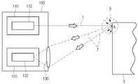
도 1은 위상차를 이용한 거리 측정 방식을 이용한 스캐너의 기본적인 동작 방법을 나타내는 블록 구성도(block diagram) 이다.1 is a block diagram showing a basic operation method of a scanner using a distance measurement method using a phase difference.
상기 스캐너(100)는 송광부(110), 수광부(120) 및 수광 렌즈(130)를 포함한다.The
이하, 상기 구성요소에 대해 차례로 간단히 살펴본다.Hereinafter, the components will be briefly described in turn.
송광부(110)는 측정 위치에 향해 일정 주파수를 가진 신호에 따라 빛의 강도를 조절하며 거리 측정용 빔(1)을 발광하는 광원(112)을 포함한다. 수광부(120)는 측정 위치에 반사되는 빛(7)을 검출하고, 검출한 빛을 이용하여 측정 신호를 생성하는 광검출부(122)를 포함한다. 또한 측정 위치에서 반사된 빛(7)을 광검출부(122)에 모아주는 수광 렌즈(130)를 포함할 수 있다.The
도 1에 도시된 바와 같이, 송광부(110)에서 주변 사물(3)의 측정 위치를 향해 거리 측정용 빔(1)을 발광한다. 거리 측정용 빔(1)이 주변 사물(3)에 도착하면 측정 위치(A)에 반사되어 여러 갈래로 반사되는 빛(5)의 형태를 가진다. 이중 스캐너(100)에 포함된 수광 렌즈(130)에 의해 여러 갈래로 반사되는 빛의 일부(7)가 수광부의(120)의 광검출부(122)로 모이게 된다.As shown in Fig. 1, the distance measuring
스캐너(100)는 측정 위치에 향해 발광한 거리 측정용 빔(1)을 생성할 때 사용한 일정 주파수를 가진 신호와 광검출부(122)에서 생성한 측정 신호를 비교하여 위상차를 측정한다. 스캐너(100)는 측정한 위상차를 기초로 스캐너(100)와 측정 위치(A) 사이의 거리를 얻을 수 있다. 자세한 내용은 도 2에서 설명하기로 한다.The
도 2는 도 1의 스캐너(100)의 위상차를 이용한 거리 측정 방식을 더욱 자세히 설명한다. 도 2에서는 일정 주파수를 가진 신호에 따라 거리 측정용 빔(1)이 스캐너(100)에서 주변 사물(3)의 측정 위치(A)에 발광되는 것을 보여준다. 또한 일정 주파수를 가진 신호에 따라 발광된 거리 측정용 빔(1)이 측정 위치(A)에 반사되어 스캐너(100)로 돌아오는 빛(7)을 보여준다. 이때, 스캐너(100)와 측정 위치(A) 사이의 거리를 D, 거리 측정용 빔(1)과 반사되어 돌아오는 빛(7)의 측정 위상차는 g, 거리 측정용 빔(1) 및 반사되어 돌아오는 빛(7)의 파장을 L(=빛의 속도 c/ 일정 주파를 가진 신호의 주파수 f)로 한다면, 다음의 수학식 1을 충족하도록 연산하여 스캐너(100)와 측정 위치 사이의 거리 D를 얻을 수 있다.FIG. 2 illustrates the distance measurement method using the phase difference of the
참고로, 측정 위상차 g는 2π(=360도) 보다 작으며, 전체 위상차는 2π(=360도)의 정수 배와 측정 위상차 g의 합에 해당한다.For reference, the measurement phase difference g is smaller than 2? (= 360 degrees), and the total phase difference corresponds to the sum of the integral multiple of 2? (= 360 degrees) and the measured phase difference g.

다음의 수학식 2를 충족하도록 연산하면 전체 위상차 및 전체 위상차를 구성하는 정수 N을 얻을 수 있다.An integer N constituting the total phase difference and the total phase difference can be obtained by calculating to satisfy the following expression (2).

이때, 수학식 2의 g1은 거리 측정용 빔(1)이 주파수 f1을 가진 신호로 생성될 때 발생하는 제1 측정 위상차이며, g2는 거리 측정용 빔(1)이 주파수 f2를 가진 신호로 생성될 때 발생하는 제2 측정 위상차이다. c는 빛의 속도이다. 스캐너(100)는 측정 위치와 같은 거리를 위치를 유지하며, 적어도 다른 주파를 가진 두 개의 신호를 이용하여 거리 측정용 빔(1)을 같은 측정 위치를 향해 각각 발광하고, 제1측정 위상차와 제2 측정 위상차를 측정한다. 주파수 f1 및 f2, 측정한 제1 측정 위상차 g1 및 제2 측정 위상차 g2, 빛의 속도 c를 이용하여 수학시 2을 충촉하도록 연산하면, 적어도 제1 전체 위상차 또는 제2 전체 위상차를 구할 수 있다. 제1 전체 위상차 또는 제2 전체 위상차를 구하면 정수 N을 얻을 수 있다. 정수 N을 얻은 후, 상기한 수학식1 또는 수학시 2를 충족하도록 연산하여 스캐너(100)와 측정 위치 사이의 거리인 D를 얻을 수 있다.In this case, g1 in the equation (2) is a first measured phase difference generated when the distance measuring
위에서 설명했듯이, 거리를 측정하기 위해 스캐너(100)는 거리 측정용 빔(1)을 생성할 때 쓰이는 신호의 주파수를 바꿔가며, 거리 측정용 빔(1)을 측정 위치에 여러 번 발광해야 한다. 이러한 방법은 빠르게 거리를 측정하지 못하는 단점을 가진다. 본 발명은 위에서 설명한 위상차를 기초로 거리를 측정하는 방법의 단점을 보완하는 방법을 제시한다.As described above, in order to measure the distance, the
도 3는 본 발명의 한 실시예에 따른 스캐너의 기본적인 동작 방법을 나타내는 블록 구성도(block diagram) 이다.3 is a block diagram illustrating a basic operation method of a scanner according to an embodiment of the present invention.
상기 스캐너(300)는 송광부(310), 수광부(320), 전원 제어부(330), 통신부(340) 및 제어부(350) 등을 포함할 수 있다.The
송광부(310)는 광원(312)과 광원렌즈(314)를 포함할 수 있다. 광원(312)은 LD(Laser Diode)와 LED(Light Emitting Diode) 등이 사용될 수 있으며, 광원 렌즈(314)는 콜리메이터 렌즈(collimator lens)가 사용되어, 광원(312)에서 나오는 빛을 평행광 또는 수렴광으로 만들 수 있다.The
수광부(320)는 광검출부(322) 및 수광렌즈(324)를 포함할 수 있다. 수광렌즈(324)는 광검출부(322)에 빛을 모아주며, 광검출부(322)는 수광렌즈(324)에서 모아준 빛을 감지하고, 감지한 빛을 이용하여 측정 신호를 생성한다.The
제어부(350)는 스캐너(300)의 전반적인 작동을 제어한다. 제어부(350)는 광원 제어부(351), 필터부(352), AGC부(Automatic Gain Control, 353), PLL부(Phase-Locked Loop, 354), ED부(Envelope Detector, 355), 위상차 비교부(356) 및 거리 계산부(357) 등을 포함할 수 있다.The
광원 제어부(351)는 제1 주파수를 가지는 제1 신호와 제2 주파수를 가지는 제2 신호를 이용하여 진폭 변조 신호를 만들고, 진폭 변조된 신호를 광원(312)에 보내준다. 필터부(351)는 광검출부(322)에서 보내준 측정 신호에서 제1 주파수를 가진 제3 신호와 제2 주파수를 가진 제4 신호를 추출한다. 필터부(352)는 제1 필터부(358)와 제2 필터부(359)를 포함할 수 있다. AGC부(353)는 필터부(352)에서 추출한 신호가 일정한 레벨의 범위로 유지 되도록 제어한다. PLL부(354)는 필터부(352)에서 분리한 신호의 주파수를 일정하게 유지하게 해준다. PLL부(354)는 제1 PLL부(361)와 제2 PLL부(362)를 포함할 수 있다. ED부(355)는 필터부(352)에서 추출한 신호의 포락선을 검파한다. 위상차 비교부(356)는 제1 신호와 제3 신호를 비교하고 측정 위상차를 측정한다. 또한 위상차 비교부(356)는 제2 신호와 제4 신호를 비교하고 측정 위상차를 측정한다. 거리 계산부(357)는 위상차 비교부(356)에서 측정한 각각의 측정 위상차와 위에서 설명했던 수학식 2를 기초로 스캐너(300)와 측정 위치 사이의 거리를 계산한다.The light
전원 공급부(330)는 제어부(350)의 제어에 의해 외부의 전원, 내부의 전원을 인가 받아 각 구성 요소들의 동작에 필요한 전원을 공급한다.The
제어부(350)는 통신부(340)를 통해 거리 계산부(357)에서 계산한 거리를 외부의 장치에 유무선으로 전송할 수 있다.The
도 3에 도시된 구성요소들이 필수적인 것은 아니어서, 그보다 많은 구성요소들을 갖거나 그보다 적은 구성요소들을 갖는 스캐너도 구현될 수도 있다.The components shown in FIG. 3 are not essential, and a scanner having more or fewer components may also be implemented.
도 3에서는 스캐너(300)와 측정 위치 사이의 거리를 거리 측정용 빔(31)을 이용하여 측정하는 것을 보여준다.In FIG. 3, the distance between the
광원 제어부(351)는 제1 주파수를 가진 제1 신호와 제2 주파수를 가진 제2 신호를 이용하여 진폭 변조 신호를 생성할 수 있다. 예를 들어 광원 제어부(351)는 높은 주파수(예: 240MHz)를 가진 제1 신호와 낮은 주파수(예: 10MHz)를 가진 제2 신호를 이용하여 진폭 변조 신호를 생성할 수 있다.The light
높은 주파수를 가진 제1 신호는 진폭 변조 신호 생성시에 캐리어 신호 역할을 할 수 있다.The first signal having a high frequency can serve as a carrier signal in the generation of the amplitude modulation signal.
제1 신호와 제2 신호의 진폭을 동일할 수 있으며, 제1 주파수와 제2 주파수의 주파수 차이는 10배 이상이 될 수 있다.The amplitude of the first signal and the amplitude of the second signal may be the same, and the frequency difference between the first frequency and the second frequency may be 10 times or more.
진폭 변조 신호에 따라 광원(312)은 빛의 강도를 조절하며 측정 위치를 향해 측정용 빔(31)을 발광한다.The
참고로 광원(312)이 높은 주파수를 가진 신호에 따라 발광할수록 거리 측정 해상도(정확도)가 높아지지만, 측정 가능한 거리는 짧아 진다. 반대로 광원(312)이 낮은 주파수를 가진 신호에 따라 발광할수록 거리 측정 해상도(정확도)가 낮아지지만, 측정 가능한 거리는 길어진다.For reference, as the
예를 들어, 위에서 예시한 높은 주파수 240MHz는 약 63cm 정도의 거리까지 정확히 측정할 수 있으며, 거리 측정 해상도는 약 0.35mm 를 가진다. 위에서 예시한 낮은 주파수 10MHz는 약 15m 정도의 거리까지 정확히 측정할 수 있으며, 거리 측정 해상도는 약 1cm 를 가진다.For example, the high frequency 240 MHz shown above can be accurately measured to a distance of about 63 cm, and the distance measurement resolution is about 0.35 mm. The low frequency 10MHz shown above can be accurately measured to a distance of about 15m, and the distance measurement resolution is about 1cm.
본 발명에서는 위에서 설명한 높은 주파수를 가진 신호를 이용하여 거리를 측정할 때와 낮은 주파수를 가진 신호를 이용하여 거리를 측정할 때의 각각의 단점을 높은 주파수를 가진 제1 신호와 낮은 주파수를 가진 제2 신호를 이용하여 진폭 변조 신호를 생성하고 진폭 변조 신호를 이용하여 거리를 측정하여 위에서 설명한 각각의 단점을 보완하고자 한다.In the present invention, each of the disadvantages of measuring the distance using the signal having the high frequency and measuring the distance using the signal having the low frequency as described above is referred to as a first signal having a high frequency and a signal having a low frequency 2 signal to generate an amplitude modulated signal and measure the distance using the amplitude modulated signal to compensate each of the disadvantages described above.
도 4는 위에서 설명한 진폭 변조 신호의 한 예를 그래프로 보여준다. 광원 제어부(351)는 상대적으로 높은 주파수(제1 주파수)를 가진 제1 신호(10)와 상대적으로 낮은 주파수(제2 주파수)를 가진 제2 신호(20)를 이용하여 진폭 변조 신호(30)을 생성한다. 광원 제어부(351)는 도 4의 진폭 변조된 신호(30)를 이용하여 광원(312)을 제어한다.FIG. 4 is a graph showing an example of the amplitude modulation signal described above. The light
다시 도3을 설명한다.3 will be described again.
광원(312)은 광원 제어부(351)에서 보내온 진폭 변조 신호에 따라 빛의 강도를 제어하며 측정 위치를 향해 측정용 빔(31)을 발광한다.The
진폭 변조 신호를 이용하면 제1 주파수와 제2 주파수를 가진 빛을 동시에 측정 위치에 발광하는 효과를 가진다. 제1 주파수와 제2 주파수를 동시에 측정 위치에 발광하는 효과를 이용하여, 거리 측정 시간을 줄일 수 있다.The use of the amplitude modulation signal has the effect of simultaneously emitting light having the first frequency and the second frequency to the measurement position. The distance measurement time can be reduced by utilizing the effect of simultaneously emitting the first frequency and the second frequency at the measurement position.
도 3에서는 광원(312)이 광원 제어부(351)에서 보내준 진폭 변조 신호에 따라 거리 측정 빔(31)을 측정 위치(T)에 향해 발광하는 것을 보여준다.3 shows that the
거리 측정용 빔(31)은 측정 위치(T)에 도착한다. 거리 측정용 빔(31)이 측정 위치(T)에 도착하면, 측정 위치에 반사되어 여러 갈래로 반사되는 빛의 형태(35)를 가진다. 이중 스캐너(300)에 포함된 수광렌즈(324)에 의해 여러 갈래로 반사되는 빛의 일부(37)가 수광부(320)의 광검출부(322)로 모이게 된다.The
광검출부(322)는 수광렌즈(324)에서 모아준 빛을 감지하여 측정 신호를 생성하고 생성한 측정 신호를 필터부(352)에 전송한다.The
필터부(352)는 제1 필터부(358)와 제2 필터부(359)를 이용하여 전송 받은 측정 신호에서 높은 주파수(제1 주파수)를 가진 제3 신호와 낮은 주파수(제2 주파수)를 가진 제4 신호를 추출할 수 있도록 구성된다. 예를 들어, 제1 필터부(358)는 밴드패스 필터 또는 하이패스 필터로 구성하여, 광검출부(322)에서 보내준 측정 신호에서 높은 주파수(제1 주파수, 예: 240MHz)를 가진 제3 신호를 추출할 수 있다. 제2 필터부(359)는 밴드패스 필터 또는 로우패스 필터로 구성하여, 광검출부(322)에서 보내준 측정 신호에서 낮은 주파수(제2 주파수, 예: 10MHz)를 가진 제4 신호를 추출할 수 있다.The
도 5는 광검출부(322)에서 전송 받은 측정 신호에서 제3 신호와 제4 신호를 추출하는 한 예를 그래프로 보여준다.FIG. 5 is a graph illustrating an example of extracting the third signal and the fourth signal from the measurement signal transmitted from the
제어부(350)는 광검출부(322)에서 보내준 측정 신호(40)에서 위에서 설명한 필터부(352)를 통해 제1 주파수를 가진 제3 신호(50)와 제2 주파수를 가진 제4 신호(60)를 각각 추출한다.The
다시 도 3을 설명한다.3 will be described again.
제3 신호와 제4 신호는 위상차 비교부(356)에 전송된다. 위상차 비교부(356)는 제1 주파수를 가진 제1 신호와 제1 주파수를 가진 제3 신호를 비교하여 제1 측정 위상차를 측정한다. 또한 위상차 비교부(356)는 제2 주파수를 가진 제2 신호와 제2 주파수를 가진 제2 주파수를 가진 제4 신호를 비교하여 제2 측정 위상차를 측정한다.The third signal and the fourth signal are transmitted to the
만약 광검출부(322)에 보내준 측정 신호에 노이즈가 많거나, 제1 필터부(358)를 거친 신호가 완벽하게 필터링 처리 되지 않았을 경우, 위상차 비교부(356)에서 제1 측정 위상차를 정확히 측정할 수 없다. 이 경우, AGC부(353)와 제1 PLL부(361)를 이용할 수 있다.If there is a large amount of noise in the measurement signal sent to the
예를 들어, 제1 필터부(358)는 추출한 제3 신호를 AGC부(353)에 전송한다. AGC부(353)는 제1 필터부(358)에서 받은 제3 신호가 일정한 레벨의 범위로 유지 하도록 한다. AGC부(353)는 처리된 제3 신호를 제1 PLL부(361)에 전송한다. 제1 PLL부(361)는 AGC부(353)에서 보내준 제3 신호의 주파수를 일정하게 유지하게 해준다. 예를 들어, 제1 PLL부(361)는 AGC부(353)에서 보내준 제3 신호의 주파수를 제1 주파수와 같게 유지해준다.For example, the
위상차 비교부(356)는 제1 신호와 제1 PLL부(361)에서 보내온 제3 신호를 비교하여 위상차를 측정한다.The
다른 예로, 제1 필터부(358)에서 추출한 제3 신호를 AGC부(353)에 전송한다. AGC부(353)는 제1 필터부(358)에서 받은 제3 신호가 일정한 레벨의 범위로 유지 하도록 한다. AGC부(353)는 처리된 제3 신호를 위상차 비교부(356)에 전송한다.As another example, the third signal extracted by the
위상차 비교부(356)는 제1 신호와 AGC부(353)에서 보내온 제3 신호를 비교하여 제1 측정 위상차를 측정한다.The
또 다른 예로, 제1 필터부(358)에서 추출한 제3 신호를 제1 PLL부(361)에 전송한다. 제1 PLL부(361)는 제1 필터부(358)에서 보내준 제3 신호의 주파수를 일정하게 유지하게 해준다. 예를 들어, 제1 PLL부(361)는 제1 필터부(358)에서 보내준 제3 신호의 주파수를 제1 주파수와 같게 유지해준다.As another example, the third signal extracted by the
위상차 비교부(356)는 제1 신호와 제1 PLL부(361)에서 보내온 제3 신호를 비교하여 제1 측정 위상차를 측정한다.The
만약 광검출부(322)에 보내준 측정 신호에 노이즈가 많거나, 제2 필터부(359)를 거친 신호가 완벽하게 필터링 처리가 되지 않았을 경우, 위상차 비교부(356)는 제2 위상차를 정확히 측정할 수 없다. 이 경우, ED부(355)와 제2 PLL부(362)를 이용할 수 있다.If there is a large amount of noise in the measurement signal sent to the
예를 들어, 제2 필터부(359)에서 추출한 제4 신호를 ED부(355)에 전송한다. ED부(355)는 제2 필터부(359)에서 받은 제4 신호의 포락선을 검파한다. ED부(355)는 처리된 제4 신호를 제2 PLL부(362)에 전송한다. 제2 PLL부(362)는 ED부(355)에서 보내준 제4 신호의 주파수를 일정하게 유지하게 해준다. 예를 들어, 제2 PLL부(362)는 ED부(355)에서 보내준 제4 신호의 주파수를 제2 주파수와 같게 유지해준다.For example, the fourth signal extracted by the
위상차 비교부(356)는 제2 신호와 제2 PLL부(362)에서 보내온 제4 신호를 비교하여 제2 측정 위상차를 측정한다.The
다른 예로, 제2 필터부(359)에서 추출한 제4 신호를 ED부(355)에 전송한다. ED부(355)는 제2 필터부(359)에서 받은 제4 신호의 포락선을 검파한다. ED부(355)는 처리된 제4 신호를 위상차 비교부(356)에 전송한다.As another example, the fourth signal extracted by the
위상차 비교부(356)는 제2 신호와 ED부(355)에서 보내온 제4 신호를 비교하여 제2 측정 위상차를 측정한다.The
또 다른 예로, 제2 필터부(359)에서 추출한 제4 신호를 제2 PLL부(362)에 전송한다. 제2 PLL부(362)는 제2 필터부(359)에서 보내준 제4 신호의 주파수를 일정하게 유지하게 해준다. 예를 들어, 제2 PLL부(362)는 제2 필터부(359)에서 보내준 제4 신호의 주파수를 제2 주파수와 같게 유지해준다.As another example, the fourth signal extracted by the
위상차 비교부(356)는 제2 신호와 제2 PLL부(362)에서 보내온 제4 신호를 비교하여 제2 측정 위상차를 측정한다.The
거리 계산부(357)는 제1 신호와 제3 신호의 주파수인 제1 주파수 (f1), 제2 신호와 제4 신호의 주파수인 제2 주파수 (f2), 빛의 속도 (c), 및 위상차 비교부(356)에서 보내온 제1 측정 위상차 (g1)와 제2 측정 위상차 (g2)를 이용하여 위에서 설명한 수학식 2를 충족시켜 제1 전체 위상차 또는 제2 전체 위상차 중 적어도 하나를 구한다. 제1 전체 위상차 또는 제2 전체 위상차를 구하면 정수 N을 얻을 수 있다.The
거리 계산부(357)는 스캐너(300)와 측정 위치 사이의 거리를 계산한다. 제1 주파수(f1), 빛의 속도(c), 제1 측정 위상차(g1) 및 정수 N 또는 제2 주파수(f2), 빛의 속도(c), 제2 측정 위상차(g2) 및 정수 N을 이용하여 위에서 설명한 수학식 2를 충족시켜 스캐너(300)와 측정 위치 사이의 거리(D)를 얻을 수 있다.The
도 6은 본 발명의 한 실시예에 따른 스캐너(300)의 동작 방법을 보여준다.6 illustrates a method of operation of the
이 실시예에 따르면 스캐너(300)는 송광부(310), 수광부(320), 전원 제어부(330), 통신부(340) 및 제어부(350) 등을 이용하여 스캐너(300)와 측정 거리 사이의 거리를 측정할 수 있다.According to this embodiment, the
먼저, 광원 제어부(351)는 제1 주파수를 가진 제1 신호와 제2 주파수를 가진 제2 신호를 이용하여 진폭 변조 신호를 생성한다(S110). 예를 들어, 광원 제어부(351)는 높은 주파수(예: 240MHz)를 가진 제1 신호와 낮은 주파수(예: 10MHz)를 가진 제2 신호를 이용하여 진폭 변조 신호를 생성한다.First, the light
광원(312)은 진폭 변조된 신호를 기초로 거리 측정 빔(31)을 측정 위치에 발광한다(S120).The
거리 측정용 빔(31)은 측정 위치에 도착한다. 측정 위치에 도착한 거리 측정용 빔(31)은 측정 위치에 반사된다.The
광검출부(322)는 측정 위치에서 거리 측정용 빔(31)이 반사되어 스캐너(300)으로 돌아오는 빛을 감지하고 측정한 빛을 이용하여 측정 신호를 생성한다(S130). 광검출부(322)는 필터부(352)에 측정 신호를 전송한다.The
필터부(352)는 감지한 신호에서 제1 주파수를 가진 제3 신호와 제2 주파수를 가진 제4 신호를 각각 추출한다(S140). 자세한 내용은 도 7에서 설명하기로 한다.The
위상차 비교부(356)는 제1 신호와 제3 신호를 비교하여 제1 측정 위상차를 측정하고, 제2 신호와 제4 신호를 비교하여 제2 측정 위상차를 측정한다(S150). 위상차 비교부(356)는 제1 주파수를 가진 제1 신호와 제1 주파수를 가진 제3 신호를 비교하여 제1 측정 위상차를 측정한다. 또한 위상차 비교부(356)는 제2 주파수를 가진 제2 신호와 제2 주파수를 가진 제4 신호를 비교하여 제2 측정 위상차를 측정한다.The
거리 계산부(357)는 제1 신호와 제3 신호의 주파수인 제1 주파수 (f1), 제2 신호와 제4 신호의 주파수인 제2 주파수 (f2), 빛의 속도 (c), 및 위상차 비교부(356)에서 보내온 제1 측정 위상차 (g1)와 제2 측정 위상차 (g2)를 이용하여 위에서 설명한 수학식 2를 충족시켜 제1 전체 위상차 또는 제2 전체 위상차 중 적어도 하나를 구한다(S160). 제1 전체 위상차 또는 제2 전체 위상차를 구하면 정수 N을 얻을 수 있다.The
거리 계산부(357)는 스캐너(300)와 측정 위치 사이의 거리를 계산한다(S170). 제1 주파수(f1), 빛의 속도(c), 제1 측정 위상차(g1) 및 정수 N 또는 제2 주파수(f2), 빛의 속도(c), 제2 측정 위상차(g2) 및 정수 N을 이용하여 위에서 설명한 수학식 2를 충족시켜 스캐너(300)와 측정 위치 사이의 거리(D)를 얻을 수 있다.The
도 7는 도 6에서 설명한 스캐너(300)의 동작 방법 중 측정 신호에서 제3 신호와 제4 신호를 추출하는 단계(S140)를 더욱 자세히 보여준다.FIG. 7 shows a step (S140) of extracting the third signal and the fourth signal from the measurement signal among the operation methods of the
제어부(350)는 제1 필터부(358)를 이용하여 광검출부(322)에서 보내준 측정신호에서 제3 신호를 추출한다(S141). 제1 필터부(358)는 밴드패스 필터 또는 하이패스 필터로 구성하여, 광검출부(322)에서 보내준 측정 신호에서 제1 주파수를 가진 제3 신호를 추출한다. 제1 필터부(358)는 추출한 제3 신호를 AGC부(353)에 전송한다.The
AGC부(353)를 작동시켜서, 제1 필터부(358)에서 받은 제3 신호가 일정한 레벨의 범위로 유지 하도록 한다(S142). AGC부(353)에서 처리된 제3 신호는 제1 PLL부(361)에 전송된다.The
제1 PLL부(361)를 작동시켜서, AGC부(353)에서 처리된 제3 신호의 주파수를 일정하게 유지하게 해준다(S143). 예를 들어, 제1 PLL부(361)는 제3 신호의 주파수를 제1 주파수와 같게 유지해준다.The
또한 아래와 같이, 제어부(350)는 제2 필터부(359)를 이용하여 광검출부(322)에서 보내준 측정 신호에서 제4 신호를 추출할 수 있다.In addition, the
제어부(350)는 제2 필터부(359)를 이용하여 광검출부(322)에서 보내준 측정신호에서 제4 신호를 추출한다(S145). 제2 필터부(359)는 밴드패스 필터 또는 로우패스 필터로 구성하여, 광검출부(322)에서 보내준 측정 신호에서 제2 주파수를 가진 제4 신호를 추출한다. 제2 필터부(359)는 추출한 제4 신호를 ED부(355)에 전송한다.The
ED부(355)를 작동시켜서, 제2 필터부(359)에서 받은 제4 신호의 포락선을 검파한다(S146). ED부(355)는 처리된 제4 신호를 제2 PLL부(362)에 전송한다.The
제2 PLL부(362)를 작동시켜, ED부(355)에서 받은 제4 신호의 주파수를 일정하게 유지하게 해준다(S147). 예를 들어, 제2 PLL부(362)는 제4 신호의 주파수를 제2 주파수와 같게 유지해준다.The
위에서 설명했듯이, 위상차 비교부(356)는 제1 신호와 제3 신호와 비교하여 제1 측정 위상차를 측정한다(S150). 또한 위상차 비교부(356)는 제2 신호와 제4 신호를 비교하여 제2 측정 위상차를 측정한다(S150).As described above, the
도 7에서는 제어부(350)가 제1 필터부(358)를 이용하여 광검출부(322)에서는 보내준 측정 신호에서 제3 신호를 추출한 후 AGC부(353)와 제1 PLL부(361)를 거쳐서 제1 측정 위상차를 측정하였다. 하지만, 도 7에서 점선으로 표시한 것과 같이 AGC부(353)를 작동시키는 단계(S142) 및 제1 PLL부(361)를 작동시키는 단계(S143)를 생략할 수 있다.7, the
예를 들어 AGC부(353)를 작동시키는 단계(S142)를 생략하거나, 제1 PLL부(361)를 작동시키는 단계 (S143)를 생략할 수도 있다. 또한 AGC부(353)를 작동시키는 단계(S142)와 제1 PLL부(361)를 작동시키는 단계 (S143) 둘 다 생략될 수 있다.For example, the step of operating the AGC unit 353 (S142) may be omitted, or the step of operating the first PLL unit 361 (S143) may be omitted. In addition, both step S142 of operating the
도 7에서는 제어부(350)가 제2 필터부(359)를 이용하여 광검출부(322)에서는 보내준 측정 신호에서 제4 신호를 추출한 후 ED부(355)와 제2 PLL부(362)를 거쳐서 제2 측정 위상차를 측정하였다. 하지만, 도 7에서 점선으로 표시한 것과 같이 ED부(355)를 작동시키는 단계(S146) 및 제2 PLL부(362)를 작동시키는 단계(S147)를 생략할 수 있다.7, the
예를 들어 ED부(353)를 작동시키는 단계(S146)를 생략하거나, 제2 PLL부(362)를 작동시키는 단계 (S147)를 생략할 수도 있다. 또한 ED부(355)를 작동시키는 단계(S146)와 제2 PLL부(362)를 작동시키는 단계(S147) 둘 다 생략할 수 있다.For example, the step of operating the ED unit 353 (S146) may be omitted, or the step of operating the second PLL unit 362 (S147) may be omitted. In addition, both step S146 of operating the
도 8, 도 9, 도 10 및 도 11은 스캐너(300)가 회전거울(500)과 같이 구성되는 예를 보여준다. 회전거울(500)은 수평하게 회전할 수 있도록 구성된다. 예를 들어, 회전거울(500)이 시계반대 방향으로 회전하면, 스캐너(300)의 거리 측정 위치는 좌측으로 이동하게 되고, 이를 통해 스캐너(300)는 측정 위치를 수평 이동하며 연속적으로 거리를 측정할 수 있다. 또한 회전거울(380)은 상하로 기울기를 조절할 수 있게 구성될 수도 있다.FIGS. 8, 9, 10 and 11 show an example in which the
도 8은 스캐너(300)와 회전거울(500)이 같이 구성된 예를 옆에서 본 모습으로 도시하였다. 광원 제어부(351)는 제1 주파수를 가진 제1 신호와 제2 주파수를 가진 제2 호를 이용하여 진폭 변조 신호를 만들고, 진폭 변조 신호를 광원(312)에 전송한다. 광원(312)은 광원 제어부(351)에서 전송해준 진폭 변조 신호에 따라 거리 측정용 빔(31)을 회전거울(500)에 발광한다. 거리 측정용 빔(31)이 회전거울(380)에 도착하면, 회전거울(500)의 표면에 반사되어 주변 사물(3)의 측정 위치에 도착한다.8 shows an example in which the
도 9는 거리 측정용 빔(31)이 측정 위치에 반사되는 모습을 도시하였다. 거리 측정용 빔(31)은 측정 위치에 도착한다. 거리 측정용 빔(31)이 측정 위치에 도착하면, 측정 위치에 반사되어 여러 갈래로 반사되는 빛의 형태를 가진다. 거리 측정용 빔(31)이 주변 사물(3)에 반사되어 여러 갈래로 반사되면, 그 중 일부의 빛(37)이 회전거울(500)에 도착한다. 회전거울(500)에 반사된 빛(37)은 스캐너(300)에 포함된 수광렌즈(324)를 통해 수광부(320)의 광검출부(322)로 모이게 된다.Fig. 9 shows a state in which the
광검출부(322)는 수광렌즈(324)에서 모아준 빛을 측정하고, 측정한 빛을 이용하여 측정 신호를 생성한다. 또한 광검출부(322)는 필터부(352)에 측정 신호를 전송한다.The
필터부(352)는 측정 신호에서 제1 주파수를 가진 제3 신호와 제2 주파수를 가진 제4 신호를 각각 추출한다.The
위상차 비교부(356)는 제1 신호와 제3 신호를 비교하여 제1 측정 위상차를 측정하고, 제2 신호와 제4 신호를 비교하여 제2 측정 위상차를 측정한다. 위상차 비교부(356)는 제1 주파수를 가진 제1 신호와 제1 주파수를 가진 제3 신호를 비교하여 제1 측정 위상차를 측정한다. 또한 위상차 비교부(356)는 제2 주파수를 가진 제2 신호와 제2 주파수를 가진 제4 신호를 비교하여 제2 측정 위상차를 측정한다.The
거리 계산부(357)는 제1 신호와 제3 신호의 주파수인 제1 주파수 (f1), 제2 신호와 제4 신호의 주파수인 제2 주파수 (f2), 빛의 속도 (c), 및 위상차 비교부(356)에서 보내온 제1 측정 위상차 (g1)와 제2 측정 위상차 (g2)를 이용하여 위에서 설명한 수학식 2를 충족시켜 제1 전체 위상차 또는 제2 전체 위상차 중 적어도 하나를 구한다. 제1 전체 위상차 또는 제2 전체 위상차를 구하면 정수 N을 얻을 수 있다.The
거리 계산부(357)는 스캐너(300)와 측정 위치 사이의 거리를 계산한다. 제1 주파수(f1), 빛의 속도(c), 제1 측정 위상차(g1) 및 정수 N 또는 제2 주파수(f2), 빛의 속도(c), 제2 측정 위상차(g2) 및 정수 N을 이용하여 위에서 설명한 수학식 2를 충족시켜 스캐너(300)와 측정 위치 사이의 거리(D)를 얻을 수 있다.The
도 10과 도 11에서는 회전거울(500)의 기울기를 상하로 조절할 수 있다는 것을 도시하였다. 회전거울(500)의 기울기를 상하로 조절하면, 거리 측정용 빔(31)이 주변 사물(3)에 도착하는 측정 위치가 상하로 조절된다. 스캐너(300)은 회전거울(500)을 이용하여 측정 위치를 상하좌우로 이동할 수 있다.10 and 11 show that the inclination of the
도 12은 진공 청소 로봇(700)에 탑재되어 사용되는 스캐너(300)를 도시하였다. 이 경우에도 스캐너(300)이 회전거울(500)과 같이 구성될 수 있다. 본 발명이 주변 사물(380)과 청소 로봇 사이의 거리를 측정하여 공간 데이터를 청소 로봇에 전송하면, 청소 로봇은 본 발명에서 전송 받은 정보를 바탕으로 동선을 정한다.12 shows the
도 13는 자동차(900)에 탑재되어 사용되는 스캐너(300)를 도시하였다. 이 경우에도 스캐너(300)이 회전거울(500)과 같이 구성될 수 있다. 본 발명이 주변 사물과 자동차 사이의 거리를 측정하여 공간 데이터를 자동차에 전송하면, 자동차는 본 발명에서 전송 받은 정보를 바탕으로 안전거리를 확보한다. 예를 들어 자동차가 운전자에게 경고방송을 할 수 도 있으며 자동차 속도를 자동 제어할 수도 있다.Fig. 13 shows a
상기와 같이 설명된 스캐너는 위에 설명된 실시예들의 구성과 방법이 한정되게 적용될 수 있는 것이 아니라, 상기 실시예들은 다양한 변형이 이루어질 수 있도록 각 실시예들의 전부 또는 일부가 선택적으로 조합되어 구성될 수도 있다.The above-described scanner can be applied to a configuration and a method of the embodiments described above in a limited manner, but the embodiments may be configured such that all or some of the embodiments are selectively combined so that various modifications can be made. have.
Claims (15)
Translated fromKorean제1 주파수를 가지는 제1 신호와 제2 주파수를 가지는 제2 신호를 이용하여 진폭 변조 신호를 생성하는 광원 제어부;
상기 진폭 변조 신호에 따라 거리 측정용 빔을 측정 위치에 발광하는 송광부;
상기 측정 위치에서 반사되어 상기 거리 측정 장치로 돌아오는 빛을 측정하여 측정 신호를 생성하는 광검출부;
상기 측정 신호에서 상기 제1 주파수를 가지는 제3 신호와 상기 제2 주파수를 가지는 제4 신호를 추출하는 필터부;
상기 제3 신호와 상기 제1 신호를 비교하여 제1 측정 위상차를 측정하고, 상기 제4 신호와 제2 신호를 비교하여 제2 측정 위상차를 측정하는 위상차 비교부; 및
상기 제1 측정 위상차와 상기 제2 측정 위상차를 기초로 상기 거리 측정 장치와 상기 측정 위치 사이의 거리를 계산하는 거리 계산부를 포함하는
거리 측정 장치.A distance measuring apparatus comprising:
A light source control unit for generating an amplitude modulation signal using a first signal having a first frequency and a second signal having a second frequency;
A light emitter for emitting a distance measuring beam to a measurement position according to the amplitude modulation signal;
A photodetector for measuring a light reflected from the measurement position and returning to the distance measurement device to generate a measurement signal;
A filter unit for extracting a third signal having the first frequency and a fourth signal having the second frequency in the measurement signal;
A phase difference comparing unit for comparing the third signal with the first signal to measure a first measured phase difference and comparing the fourth signal and the second signal to measure a second measured phase difference; And
And a distance calculating section for calculating a distance between the distance measuring apparatus and the measurement position based on the first measured phase difference and the second measured phase difference
Distance measuring device.
상기 거리 계산부는
상기 제1 측정 위상차와 상기 제2 측정 위상차를 기초로
상기 제1 신호와 상기 제3 신호 사이의 제1 전체 위상차 또는
상기 제2 신호와 상기 제4 신호 사이의 제2 전체 위상차 중 적어도 하나를 구하고,
상기 제1 전체 위상차 또는 상기 제2 전체 위상차를 이용하여 상기 거리 측정 장치와 상기 측정 위치 사이의 거리를 계산하는
거리 측정 장치.The method according to claim 1,
The distance calculator
Based on the first measured phase difference and the second measured phase difference
A first total phase difference between the first signal and the third signal, or
And a second total phase difference between the second signal and the fourth signal,
Calculating a distance between the distance measuring apparatus and the measurement position using the first total phase difference or the second total phase difference
Distance measuring device.
상기 제1 측정 위상차는 360도보다 작고,
상기 제2 측정 위상차는 360도보다 작으며,
상기 제1 전체 위상차는 360도의 정수 배와 상기 제1 측정 위상차의 합에 해당하고,
상기 제2 전체 위상차는 360도의 정수 배와 상기 제2 측정 위상차의 합에 해당하는
거리 측정 장치.3. The method of claim 2,
Wherein the first measured phase difference is less than 360 degrees,
Wherein the second measured phase difference is less than 360 degrees,
Wherein the first total phase difference corresponds to a sum of an integer multiple of 360 degrees and the first measured phase difference,
Wherein the second total phase difference is an integral multiple of 360 degrees and the second measured phase difference
Distance measuring device.
상기 거리 계산부는
상기 제1 주파수, 상기 제2 주파수, 상기 제1 측정 위상차와, 및 상기 제2 측정 위상차를 기초로
상기 제1 전체 위상차 또는 상기 제2 전체 위상차 중 적어도 하나를 구하는
거리 측정 장치.3. The method of claim 2,
The distance calculator
Based on the first frequency, the second frequency, the first measured phase difference, and the second measured phase difference
Obtaining at least one of the first total phase difference and the second total phase difference
Distance measuring device.
상기 필터부는 제1 필터부와 제2 필터부를 포함하고,
상기 제1 필터부는 하이패스 필터나 밴드패스 필터로 구성되어 상기 측정 신호에서 상기 제3 신호를 추출하고,
상기 제2 필터부는 로우패스 필터나 밴드패스 필터로 구성되어 상기 측정 신호에서 상기 제4 신호를 추출하는
거리 측정 장치.The method according to claim 1,
Wherein the filter unit includes a first filter unit and a second filter unit,
Wherein the first filter unit comprises a high pass filter or a band pass filter to extract the third signal from the measurement signal,
Wherein the second filter unit comprises a low-pass filter and a band-pass filter, and extracts the fourth signal from the measurement signal
Distance measuring device.
상기 제3 신호를 일정한 레벨의 범위로 유지하게 하는 AGC(Automatic Gain Control)부를 더 포함하는
거리 측정 장치.6. The method of claim 5,
And an AGC (Automatic Gain Control) unit for maintaining the third signal in a predetermined level range
Distance measuring device.
상기 제3 신호의 주파수를 제1 주파수로 일정하게 유지해주는 제1 PLL(Phase-Locked Loop)부를 더 포함하는
거리 측정 장치.6. The method of claim 5,
And a first PLL (Phase-Locked Loop) unit for keeping the frequency of the third signal constant at a first frequency
Distance measuring device.
상기 제4 신호의 포락선을 검파하는 ED(Envelope Detector)부를 더 포함하는
거리 측정 장치.6. The method of claim 5,
And an ED (Envelope Detector) unit for detecting an envelope of the fourth signal
Distance measuring device.
상기 제4 신호의 주파수를 제2 주파수로 일정하게 유지해주는 제2 PLL(Phase-Locked Loop)부를 더 포함하는
거리 측정 장치.6. The method of claim 5,
And a second PLL (Phase-Locked Loop) unit for keeping the frequency of the fourth signal constant at a second frequency
Distance measuring device.
제1 주파수를 가지는 제1 신호와 제2 주파수를 가지는 제2 신호를 이용하여 진폭 변조 신호를 생성하는 단계;
상기 진폭 변조 신호에 따라 거리 측정용 빔을 측정 위치에 발광하는 단계;
상기 측정 위치에 반사되어 상기 거리 측정 장치로 돌아오는 빛을 측정하여 측정 신호를 생성하는 단계;
상기 측정 신호에서 상기 제1 주파수를 가지는 제3 신호와 상기 제2 주파수를 가지는 제4 신호를 추출하는 단계;
상기 제3 신호와 상기 제1 신호를 비교하여 제1 측정 위상차를 측정하고, 상기 제4 신호와 제2 신호를 비교하여 제2 측정 위상차를 측정하는 단계; 및
상기 제1 측정 위상차와 상기 제2 측정 위상차를 기초로 상기 거리 측정 장치와 상기 측정 위치 사이의 거리를 계산하는 단계를 포함하는
동작 방법.A method of operating a distance measuring device,
Generating an amplitude modulated signal using a first signal having a first frequency and a second signal having a second frequency;
Emitting a beam for distance measurement to a measurement position according to the amplitude modulation signal;
Measuring light reflected on the measurement position and returning to the distance measurement device to generate a measurement signal;
Extracting a third signal having the first frequency and a fourth signal having the second frequency in the measurement signal;
Comparing the third signal with the first signal to measure a first measured phase difference, and comparing the fourth signal and the second signal to measure a second measured phase difference; And
Calculating a distance between the distance measuring device and the measurement position based on the first measured phase difference and the second measured phase difference
How it works.
상기 거리를 계산하는 단계는
상기 제1 측정 위상차와 상기 제2 측정 위상차를 기초로
상기 제1 신호와 상기 제3 신호 사이의 제1 전체 위상차 또는
상기 제2 신호와 상기 제4 신호 사이의 제2 전체 위상차 중 적어도 하나를 구하는 단계와,
상기 제1 전체 위상차 또는 상기 제2 전체 위상차를 이용하여 상기 거리 측정 장치와 상기 측정 위치 사이의 거리를 계산하는 단계를 포함하는
동작 방법.11. The method of claim 10,
The step of calculating the distance
Based on the first measured phase difference and the second measured phase difference
A first total phase difference between the first signal and the third signal, or
Obtaining at least one of a second total phase difference between the second signal and the fourth signal;
And calculating the distance between the distance measuring device and the measurement position using the first total phase difference or the second total phase difference
How it works.
상기 제1 측정 위상차는 360도보다 작고,
상기 제2 측정 위상차는 360도보다 작으며,
상기 제1 전체 위상차는 360도의 정수 배와 상기 제1 측정 위상차의 합에 해당하고,
상기 제2 전체 위상차는 360도의 정수 배와 상기 제2 측정 위상차의 합에 해당하는
동작 방법.12. The method of claim 11,
Wherein the first measured phase difference is less than 360 degrees,
Wherein the second measured phase difference is less than 360 degrees,
Wherein the first total phase difference corresponds to a sum of an integer multiple of 360 degrees and the first measured phase difference,
Wherein the second total phase difference is an integral multiple of 360 degrees and the second measured phase difference
How it works.
상기 제1 전체 위상차 또는 상기 제2 전체 위상차 중 적어도 하나를 구하는 단계는
상기 제1 주파수, 상기 제2 주파수, 상기 제1 측정 위상차와, 및 상기 제2 측정 위상차를 기초로
상기 제1 전체 위상차 또는 상기 제2 전체 위상차 중 적어도 하나를 구하는 단계를 포함하는
동작 방법.12. The method of claim 11,
Wherein the step of obtaining at least one of the first total phase difference and the second total phase difference
Based on the first frequency, the second frequency, the first measured phase difference, and the second measured phase difference
And obtaining at least one of the first total phase difference or the second total phase difference
How it works.
상기 측정 신호에서 상기 제1 주파수를 가지는 상기 제3 신호를 추출하는 단계는
상기 제3 신호를 일정한 레벨의 범위로 유지하게 하는 단계 또는
상기 제3 신호의 주파수를 제1 주파수로 일정하게 유지해주는 단계 중 적어도 하나의 단계를 포함하는
동작 방법.11. The method of claim 10,
The step of extracting the third signal having the first frequency from the measurement signal
Maintaining the third signal at a constant level of range or
And maintaining the frequency of the third signal constant at a first frequency.
How it works.
상기 측정 신호에서 상기 제2 주파수를 가지는 상기 제4 신호를 추출하는 단계는
상기 제4 신호를 검파하는 단계 또는
상기 제4 신호의 주파수를 제2 주파수로 일정하게 유지해주는 단계 중 적어도 하나의 단계를 포함하는
동작 방법.11. The method of claim 10,
The step of extracting the fourth signal having the second frequency from the measurement signal
Detecting the fourth signal or
And maintaining the frequency of the fourth signal constant at a second frequency.
How it works.
Priority Applications (1)
| Application Number | Priority Date | Filing Date | Title |
|---|---|---|---|
| KR20130038456AKR20140122002A (en) | 2013-04-09 | 2013-04-09 | Distance measuring scanner and operating method thereof |
Applications Claiming Priority (1)
| Application Number | Priority Date | Filing Date | Title |
|---|---|---|---|
| KR20130038456AKR20140122002A (en) | 2013-04-09 | 2013-04-09 | Distance measuring scanner and operating method thereof |
Publications (1)
| Publication Number | Publication Date |
|---|---|
| KR20140122002Atrue KR20140122002A (en) | 2014-10-17 |
Family
ID=51993268
Family Applications (1)
| Application Number | Title | Priority Date | Filing Date |
|---|---|---|---|
| KR20130038456AWithdrawnKR20140122002A (en) | 2013-04-09 | 2013-04-09 | Distance measuring scanner and operating method thereof |
Country Status (1)
| Country | Link |
|---|---|
| KR (1) | KR20140122002A (en) |
Cited By (3)
| Publication number | Priority date | Publication date | Assignee | Title |
|---|---|---|---|---|
| KR20170088388A (en)* | 2015-10-22 | 2017-08-01 | 광저우 엑스에어크래프트 테크놀로지 씨오 엘티디 | Unmanned aerial vehicle(uav) and distance measuring and filtering device and method thereof and distance measurement method based on same |
| KR20190062923A (en)* | 2017-11-29 | 2019-06-07 | 에이테크솔루션(주) | Apparatus and method for measuring distance using tof camera |
| JP2023040126A (en)* | 2015-03-25 | 2023-03-22 | ウェイモ エルエルシー | Vehicle with multiple light detection and ranging devices (lidars) |
- 2013
- 2013-04-09KRKR20130038456Apatent/KR20140122002A/ennot_activeWithdrawn
Cited By (4)
| Publication number | Priority date | Publication date | Assignee | Title |
|---|---|---|---|---|
| JP2023040126A (en)* | 2015-03-25 | 2023-03-22 | ウェイモ エルエルシー | Vehicle with multiple light detection and ranging devices (lidars) |
| US12332379B2 (en) | 2015-03-25 | 2025-06-17 | Waymo Llc | Vehicle with multiple light detection and ranging devices (LIDARs) |
| KR20170088388A (en)* | 2015-10-22 | 2017-08-01 | 광저우 엑스에어크래프트 테크놀로지 씨오 엘티디 | Unmanned aerial vehicle(uav) and distance measuring and filtering device and method thereof and distance measurement method based on same |
| KR20190062923A (en)* | 2017-11-29 | 2019-06-07 | 에이테크솔루션(주) | Apparatus and method for measuring distance using tof camera |
Similar Documents
| Publication | Publication Date | Title |
|---|---|---|
| US11709231B2 (en) | Real time gating and signal routing in laser and detector arrays for LIDAR application | |
| US10288734B2 (en) | Sensing system and method | |
| JP6942966B2 (en) | Object detection device and mobile device | |
| JP5576294B2 (en) | Laser sensor system based on self-mixing interference | |
| US10215857B2 (en) | Depth sensor module and depth sensing method | |
| JP6922187B2 (en) | Distance measuring device, surveillance camera, 3D measuring device, moving object, robot and light source drive condition setting method | |
| EP1966627B1 (en) | Device and method for measuring relative movement | |
| US20180074198A1 (en) | Optical beam identification using optical demodulation | |
| WO2019237911A1 (en) | Light emitting module, light emitting unit, light signal detection module, optical system and laser radar system | |
| US9645239B2 (en) | Laser tracker comprising interferometer and absolute distance measuring unit, and calibration method for a laser tracker | |
| JP2018077143A (en) | Ranging device, moving body, robot, three-dimensional measuring device, surveillance camera, and ranging method | |
| JP2018066609A (en) | Ranging device, surveillance camera, three-dimensional measuring device, moving object, robot, and ranging method | |
| KR102664396B1 (en) | LiDAR device and operating method of the same | |
| US9041918B2 (en) | Measuring apparatus and referencing method for a digital laser distance meter, and laser distance meter | |
| CN111610510A (en) | lidar system | |
| KR20140122002A (en) | Distance measuring scanner and operating method thereof | |
| JP2018021776A (en) | Parallax calculation system, moving object, and program | |
| US9798005B2 (en) | Three-dimensional space measurement device and method for operating same | |
| KR102090502B1 (en) | Distance measuring device and method thereof | |
| US20080192229A1 (en) | Relative Movement Sensor Comprising Multiple Lasers | |
| KR102065024B1 (en) | Distance measuring scanner and operating method thereof | |
| US20220107409A1 (en) | Optical sensor device for determining distance to object and velocity of the object, and identifying the shape and structure of the object | |
| KR20150018026A (en) | 3 demensional camera | |
| CN210690804U (en) | Laser radar system | |
| KR102188878B1 (en) | Distance measuring scanner and operating method thereof |
Legal Events
| Date | Code | Title | Description |
|---|---|---|---|
| PA0109 | Patent application | Patent event code:PA01091R01D Comment text:Patent Application Patent event date:20130409 | |
| PG1501 | Laying open of application | ||
| PC1203 | Withdrawal of no request for examination | ||
| WITN | Application deemed withdrawn, e.g. because no request for examination was filed or no examination fee was paid |