KR20140116724A - Electrode structure integrated with deflector - Google Patents
Electrode structure integrated with deflectorDownload PDFInfo
- Publication number
- KR20140116724A KR20140116724AKR1020130031649AKR20130031649AKR20140116724AKR 20140116724 AKR20140116724 AKR 20140116724AKR 1020130031649 AKR1020130031649 AKR 1020130031649AKR 20130031649 AKR20130031649 AKR 20130031649AKR 20140116724 AKR20140116724 AKR 20140116724A
- Authority
- KR
- South Korea
- Prior art keywords
- deflector
- electrode
- structure according
- electrode structure
- fluid
- Prior art date
- Legal status (The legal status is an assumption and is not a legal conclusion. Google has not performed a legal analysis and makes no representation as to the accuracy of the status listed.)
- Ceased
Links
- 239000003054catalystSubstances0.000claimsabstractdescription4
- 239000012530fluidSubstances0.000claimsdescription57
- 238000003491arrayMethods0.000claimsdescription2
- 238000003487electrochemical reactionMethods0.000abstractdescription11
- 238000000909electrodialysisMethods0.000abstractdescription9
- 238000010612desalination reactionMethods0.000abstractdescription6
- 239000003792electrolyteSubstances0.000abstractdescription6
- 230000004913activationEffects0.000abstract1
- 239000000463materialSubstances0.000abstract1
- 239000012528membraneSubstances0.000description23
- 230000001965increasing effectEffects0.000description8
- 238000000926separation methodMethods0.000description6
- 125000006850spacer groupChemical group0.000description5
- 239000000126substanceSubstances0.000description5
- 238000006243chemical reactionMethods0.000description4
- 230000004048modificationEffects0.000description4
- 238000012986modificationMethods0.000description4
- 238000004519manufacturing processMethods0.000description3
- 239000000243solutionSubstances0.000description3
- 238000007599dischargingMethods0.000description2
- 239000008151electrolyte solutionSubstances0.000description2
- 238000005516engineering processMethods0.000description2
- 230000002452interceptive effectEffects0.000description2
- 239000007788liquidSubstances0.000description2
- 238000010248power generationMethods0.000description2
- 239000003011anion exchange membraneSubstances0.000description1
- 238000005341cation exchangeMethods0.000description1
- 238000010586diagramMethods0.000description1
- 230000000694effectsEffects0.000description1
- 230000001939inductive effectEffects0.000description1
- 230000035699permeabilityEffects0.000description1
- 230000000704physical effectEffects0.000description1
- 239000002952polymeric resinSubstances0.000description1
- 238000006479redox reactionMethods0.000description1
- 238000007493shaping processMethods0.000description1
- 238000004904shorteningMethods0.000description1
- 238000005507sprayingMethods0.000description1
- 230000003746surface roughnessEffects0.000description1
- 229920003002synthetic resinPolymers0.000description1
- 239000011800void materialSubstances0.000description1
Images


Classifications
- H—ELECTRICITY
- H01—ELECTRIC ELEMENTS
- H01M—PROCESSES OR MEANS, e.g. BATTERIES, FOR THE DIRECT CONVERSION OF CHEMICAL ENERGY INTO ELECTRICAL ENERGY
- H01M8/00—Fuel cells; Manufacture thereof
- H01M8/02—Details
- H01M8/0202—Collectors; Separators, e.g. bipolar separators; Interconnectors
- H01M8/0258—Collectors; Separators, e.g. bipolar separators; Interconnectors characterised by the configuration of channels, e.g. by the flow field of the reactant or coolant
- H01M8/026—Collectors; Separators, e.g. bipolar separators; Interconnectors characterised by the configuration of channels, e.g. by the flow field of the reactant or coolant characterised by grooves, e.g. their pitch or depth
- H—ELECTRICITY
- H01—ELECTRIC ELEMENTS
- H01M—PROCESSES OR MEANS, e.g. BATTERIES, FOR THE DIRECT CONVERSION OF CHEMICAL ENERGY INTO ELECTRICAL ENERGY
- H01M8/00—Fuel cells; Manufacture thereof
- H01M8/02—Details
- H01M8/0271—Sealing or supporting means around electrodes, matrices or membranes
- H01M8/0273—Sealing or supporting means around electrodes, matrices or membranes with sealing or supporting means in the form of a frame
- H—ELECTRICITY
- H01—ELECTRIC ELEMENTS
- H01M—PROCESSES OR MEANS, e.g. BATTERIES, FOR THE DIRECT CONVERSION OF CHEMICAL ENERGY INTO ELECTRICAL ENERGY
- H01M8/00—Fuel cells; Manufacture thereof
- H01M8/22—Fuel cells in which the fuel is based on materials comprising carbon or oxygen or hydrogen and other elements; Fuel cells in which the fuel is based on materials comprising only elements other than carbon, oxygen or hydrogen
- H01M8/227—Dialytic cells or batteries; Reverse electrodialysis cells or batteries
- B—PERFORMING OPERATIONS; TRANSPORTING
- B01—PHYSICAL OR CHEMICAL PROCESSES OR APPARATUS IN GENERAL
- B01D—SEPARATION
- B01D61/00—Processes of separation using semi-permeable membranes, e.g. dialysis, osmosis or ultrafiltration; Apparatus, accessories or auxiliary operations specially adapted therefor
- B01D61/42—Electrodialysis; Electro-osmosis ; Electro-ultrafiltration; Membrane capacitive deionization
- B01D61/44—Ion-selective electrodialysis
- B01D61/46—Apparatus therefor
- B01D61/50—Stacks of the plate-and-frame type
- B—PERFORMING OPERATIONS; TRANSPORTING
- B01—PHYSICAL OR CHEMICAL PROCESSES OR APPARATUS IN GENERAL
- B01D—SEPARATION
- B01D61/00—Processes of separation using semi-permeable membranes, e.g. dialysis, osmosis or ultrafiltration; Apparatus, accessories or auxiliary operations specially adapted therefor
- B01D61/42—Electrodialysis; Electro-osmosis ; Electro-ultrafiltration; Membrane capacitive deionization
- B01D61/44—Ion-selective electrodialysis
- B01D61/52—Accessories; Auxiliary operation
- C—CHEMISTRY; METALLURGY
- C02—TREATMENT OF WATER, WASTE WATER, SEWAGE, OR SLUDGE
- C02F—TREATMENT OF WATER, WASTE WATER, SEWAGE, OR SLUDGE
- C02F1/00—Treatment of water, waste water, or sewage
- C02F1/46—Treatment of water, waste water, or sewage by electrochemical methods
- C02F1/469—Treatment of water, waste water, or sewage by electrochemical methods by electrochemical separation, e.g. by electro-osmosis, electrodialysis, electrophoresis
- C02F1/4693—Treatment of water, waste water, or sewage by electrochemical methods by electrochemical separation, e.g. by electro-osmosis, electrodialysis, electrophoresis electrodialysis
- H—ELECTRICITY
- H01—ELECTRIC ELEMENTS
- H01M—PROCESSES OR MEANS, e.g. BATTERIES, FOR THE DIRECT CONVERSION OF CHEMICAL ENERGY INTO ELECTRICAL ENERGY
- H01M8/00—Fuel cells; Manufacture thereof
- H01M8/18—Regenerative fuel cells, e.g. redox flow batteries or secondary fuel cells
- H01M8/184—Regeneration by electrochemical means
- H01M8/188—Regeneration by electrochemical means by recharging of redox couples containing fluids; Redox flow type batteries
- Y—GENERAL TAGGING OF NEW TECHNOLOGICAL DEVELOPMENTS; GENERAL TAGGING OF CROSS-SECTIONAL TECHNOLOGIES SPANNING OVER SEVERAL SECTIONS OF THE IPC; TECHNICAL SUBJECTS COVERED BY FORMER USPC CROSS-REFERENCE ART COLLECTIONS [XRACs] AND DIGESTS
- Y02—TECHNOLOGIES OR APPLICATIONS FOR MITIGATION OR ADAPTATION AGAINST CLIMATE CHANGE
- Y02E—REDUCTION OF GREENHOUSE GAS [GHG] EMISSIONS, RELATED TO ENERGY GENERATION, TRANSMISSION OR DISTRIBUTION
- Y02E10/00—Energy generation through renewable energy sources
- Y02E10/30—Energy from the sea, e.g. using wave energy or salinity gradient
- Y—GENERAL TAGGING OF NEW TECHNOLOGICAL DEVELOPMENTS; GENERAL TAGGING OF CROSS-SECTIONAL TECHNOLOGIES SPANNING OVER SEVERAL SECTIONS OF THE IPC; TECHNICAL SUBJECTS COVERED BY FORMER USPC CROSS-REFERENCE ART COLLECTIONS [XRACs] AND DIGESTS
- Y02—TECHNOLOGIES OR APPLICATIONS FOR MITIGATION OR ADAPTATION AGAINST CLIMATE CHANGE
- Y02E—REDUCTION OF GREENHOUSE GAS [GHG] EMISSIONS, RELATED TO ENERGY GENERATION, TRANSMISSION OR DISTRIBUTION
- Y02E60/00—Enabling technologies; Technologies with a potential or indirect contribution to GHG emissions mitigation
- Y02E60/30—Hydrogen technology
- Y02E60/50—Fuel cells
- Y—GENERAL TAGGING OF NEW TECHNOLOGICAL DEVELOPMENTS; GENERAL TAGGING OF CROSS-SECTIONAL TECHNOLOGIES SPANNING OVER SEVERAL SECTIONS OF THE IPC; TECHNICAL SUBJECTS COVERED BY FORMER USPC CROSS-REFERENCE ART COLLECTIONS [XRACs] AND DIGESTS
- Y02—TECHNOLOGIES OR APPLICATIONS FOR MITIGATION OR ADAPTATION AGAINST CLIMATE CHANGE
- Y02P—CLIMATE CHANGE MITIGATION TECHNOLOGIES IN THE PRODUCTION OR PROCESSING OF GOODS
- Y02P70/00—Climate change mitigation technologies in the production process for final industrial or consumer products
- Y02P70/50—Manufacturing or production processes characterised by the final manufactured product
Landscapes
- Life Sciences & Earth Sciences (AREA)
- Engineering & Computer Science (AREA)
- Manufacturing & Machinery (AREA)
- Sustainable Development (AREA)
- Sustainable Energy (AREA)
- Chemical & Material Sciences (AREA)
- Chemical Kinetics & Catalysis (AREA)
- Electrochemistry (AREA)
- General Chemical & Material Sciences (AREA)
- Separation Using Semi-Permeable Membranes (AREA)
Abstract
Description
Translated fromKorean본 발명은 전기화학반응을 내포하는 전기투석 담수화, 흐름전극 담수화장치, 레독스흐름전지, 역전기투석 발전 시스템에 사용되는 전해질 린스 용액이 음전극 및 양전극과 분리막 사이를 흐르며, 전기화학 효율 향상을 위해 반응 면적 증가 및 유체 흐름에 난류를 형성시키기 위해 편향기가 형성된 전극 구조체에 관한 것이다.
The present invention relates to an electrolytic rinse solution used for electrodialysis desalination, flow electrode desalination apparatus, redox flow cell, and reverse electrodialysis power generation system containing an electrochemical reaction flows between a negative electrode and a positive electrode and a separator, To an electrode structure in which a deflector is formed to increase the reaction area and to create turbulence in the fluid flow.
전기화학반응은 이차전지분야에서부터 전기투석 담수화, 역전기투석 발전, 흐름전극 담수화장치, 레독스흐름전지, 의료전기투석까지 다양한 분야에서 화학에너지와 전기에너지간의 변환을 유도하는 핵심적인 기술로 발전을 하고 있다. 최근 기술발전 방향은 양산화를 고려하여 전해질 흐름 시스템을 기본적으로 채택하고 있다. 흐름 전해질 용액의 전기화학반응은 음/양전극표면에서 산화환원 반응을 통해 화학에너지를 전기에너지로 변환을 시키게 된다. 따라서 에너지 효율 증대를 위해 흐름 전해질용액은 가능한 전기화학반응을 최대한으로 끌어올리는 것이 매우 중요한 기술로 인식되고 있다.The electrochemical reaction evolves from the secondary cell field to the core technology that induces the conversion between chemical energy and electric energy in various fields such as electrodialysis desalination, reverse electrodialysis, flow electrode desalination, redox flow cell, and medical electrodialysis. . Recently, the technology development direction is basically adopting the electrolytic flow system considering mass production. The electrochemical reaction of the flow electrolyte solution causes the chemical energy to be converted into electric energy through the redox reaction on the negative / positive electrode surface. Therefore, in order to increase the energy efficiency, it is recognized that it is very important to increase the electrochemical reaction to the maximum possible level for the flow electrolyte solution.
전기화학반응은 충돌에 의한 에너지변환을 기초로 하고 있다. 일반적으로 온도는 시스템내부의 분자 운동에너지의 측정이기 때문에, 더 높은 온도에서는 분자의 평균 운동에너지가 증가되어 단위 시간당 충돌 횟수를 증가시켜 화학반응속도를 향상시킨다. 하지만, 시스템의 온도조절은 운행비용의 증가뿐만 아니라 분리막 손상 및 전극 수명 단축과 같은 단점을 초래한다. 다른 방법으로는 표면적 증가와 더불어 유체 흐름에 난류를 유도하여 충돌 횟수를 증가시키는 것이다. 이를 위해 현재 대부분의 모듈에는 전극과 분리막 사이에 비전도성 고분자수지 계열의 스페이서(spacer)를 사용하여 유체 흐름에 난류를 유도하고 있지만 그림자효과(shadow effect)로 인해 에너지 효율이 감소하는 문제점을 보이고 있다. 또한, 분리형 스페이서는 모듈 조립 시 불량이 자주 발생할 뿐만 아니라, 내부 손실압력이 매우 높아 에너지 효율이 저하되는 단점을 가지고 있다. 따라서 기존 스페이서를 사용하지 않고 전기화학반응을 증대시킬 수 있는 새로운 시스템 개발의 필요성이 점차 커지고 있다.Electrochemical reactions are based on energy conversion by impact. In general, the temperature is a measure of the molecular kinetic energy inside the system, so at higher temperatures the average kinetic energy of the molecules is increased, increasing the number of collisions per unit time and improving the chemical reaction rate. However, the temperature control of the system has disadvantages such as not only an increase in operation cost but also damage of the membrane and shortening of electrode life. Another way is to increase the number of collisions by inducing turbulence in the fluid flow with increasing surface area. For this purpose, most of current modules use a nonconductive polymer resin spacer between the electrodes and the separator to induce turbulence in the fluid flow, but the energy efficiency is reduced due to the shadow effect . In addition, the detachable spacer has a disadvantage in that not only the failure occurs frequently in assembling the module but also the internal loss pressure is very high and the energy efficiency is lowered. Therefore, there is a growing need to develop a new system capable of increasing the electrochemical reaction without using existing spacers.
최근 역전기투석 발전 시스템에서 전해질 린스 전극에 망사형 구조체를 사용하는 연구결과가 보고되었다. [Journal of membrane science, 2011, 234-242, power generation using profiled membranes in reverse electrodialysis] 하지만, 이들 망사형 구조는 기존 스페이서의 구조와 유사하여 내부 압력 증가 문제점을 계속적으로 내포하고 있어, 표면적을 크게 하기위해 메쉬(mesh)크기를 증가시키지 못하는 단점을 가지고 있다. 따라서 전해질 린스 용액의 흐름의 내부 압력 손실을 최소화할 뿐만 아니라, 에너지 효율을 증대시키기 위한 새로운 전극구조체 개발의 필요성이 요구되고 있다.
Recently, research results using a mesh-like structure on electrolyte rinse electrodes in a reverse electrodialysis power generation system have been reported. However, these mesh-like structures are similar to those of conventional spacers, and thus have problems of increasing the inner pressure continuously. Therefore, the surface area is increased The mesh size can not be increased. Therefore, there is a need to develop a new electrode structure that not only minimizes internal pressure loss of the electrolyte rinse solution, but also increases energy efficiency.
상기의 문제점을 해결하기 위해 안출된 본 발명의 목적은, 전극표면에 돌출형 편향기를 일체형으로 유도하여, 전기화학 반응 면적 증가와 더불어 유체흐름에 난류를 발생시켜 에너지 효율을 증가시킬 수 있는 전해질 린스 흐름 전극 구조체를 제공하는데 있다.
SUMMARY OF THE INVENTION An object of the present invention which has been devised to solve the above problems is to provide an electrolytic rinse which can induce a protruding deflector integrally on the surface of an electrode and increase the electrochemical reaction area, To provide a flow electrode structure.
상기의 목적을 달성하기 위한 본 발명은, 전극플레이트; 상기 전극플레이트의 테두리에 형성되는 개스킷; 및 상기 전극플레이트의 표면에 형성되는 편향기를 포함하고, 상기 전극플레이트에는 상기 개스킷과 상기 전극플레이트에 한정되는 공간을 흐르는 전극유체가 공급 및 배출되는 전극유체공급홀과 전극유체배출홀이 형성되며, 제1유체와 제2유체가 유통되는 바이패스관이 설치되는 것을 특징으로 하는 편향기 일체형 전극 구조체이다.According to an aspect of the present invention, A gasket formed at an edge of the electrode plate; And a deflector formed on a surface of the electrode plate, wherein the electrode plate is provided with an electrode fluid supply hole and an electrode fluid discharge hole through which electrode fluid flowing in a space defined by the gasket and the electrode plate is supplied and discharged, And a bypass pipe through which the first fluid and the second fluid are communicated is provided.
또, 상기 전극구조체는 상기 개스킷에 부착되어 상기 전극플레이트에 대하여 이격되어 설치되는 전극분리막을 추가로 포함할 수 있다.The electrode structure may further include an electrode separator attached to the gasket and spaced apart from the electrode plate.
상기 편향기의 구조는 모듈의 사용목적에 따라 다양한 형태로 제작될 수 있다. 따라서 상기 편향기는 유체흐름의 조절을 위해 일종 이상의 패턴이 형성될 수 있다. 또, 상기 편향기는 반구, 원통형, 원뿔형, 사각기둥형 등 다양한 모양을 가지는 것을 특징으로 한다.The structure of the deflector may be variously formed according to the purpose of use of the module. Accordingly, the deflector may be formed with one or more patterns for adjusting the fluid flow. The deflector may have various shapes such as a hemispherical shape, a cylindrical shape, a conical shape, a square column shape, and the like.
상기 편향기는 상기 개스킷의 높이보다 낮게 형성되는 것을 특징으로 한다.And the deflector is formed to be lower than the height of the gasket.
또, 상기 편향기는 상기 개스킷의 높이와 같게 형성되는 것을 특징으로 한다.Further, the deflector is formed to have the same height as the gasket.
또, 편형기에는 촉매가 도포되는 것을 특징으로 한다.Further, the shaping device is characterized in that the catalyst is applied.
또, 상기 편향기는 단면형상이 다른 2 이상의 편향기로 이루어지는 것을 특징으로 한다.Further, the deflector is characterized by being composed of two or more deflectors having different sectional shapes.
또, 상기 편향기는 복수개가 일정피치로 배치되어 편향기열을 이루고, 복수의 편향기열이 일정간격으로 배치되는 것을 특징으로 한다.A plurality of deflectors are arranged at a constant pitch to form a deflector array, and a plurality of deflector arrays are arranged at regular intervals.
또, 인접하는 편향기열은 피치의 위상차를 가지는 것을 특징으로 한다.Further, the adjacent deflector rows have a phase difference of pitch.
또, 상기 편향기는 2 이상의 다른 세그먼트로 이루어지는 것을 특징으로 한다. 이 때, 상기 세그먼트는 다양한 형태로 구성될 수 있다. 복수의 세그먼트는 편향기의 높이 방향으로 적층하여 배치되거나 편향기의 폭방향으로 부착하여 배치될 수 있다. 또, 복수의 세그먼트는, 하나의 세그먼트의 외표면을 다른 세그먼트가 감싸거나, 하나의 세그먼트의 내부에 다른 세그먼트가 삽입된 상태일 수 있다.Further, the deflector is characterized by being composed of two or more different segments. At this time, the segments may be configured in various forms. The plurality of segments may be stacked in the height direction of the deflector or disposed in the width direction of the deflector. In addition, a plurality of segments may be a state in which another segment surrounds the outer surface of one segment, or another segment is inserted in one segment.
또, 상기 편향기는 편향기바디의 외표면으로 돌기가 형성된 것을 특징으로 한다. 이 때, 상기 돌기는 고리형태인 것을 특징으로 한다.The deflector is characterized in that a protrusion is formed on the outer surface of the deflector body. At this time, the protrusions are ring-shaped.
또, 상기 돌기는 편향기바디에 관통홀이 형성되는 것도 가능하다.
It is also possible that the protrusion has a through hole formed in the deflector body.
본 발명을 통하여, 편향기 설치에 의해 표면적 증가 및 전해질 린스 용액에 난류를 발생시켜 전해질이 전극과 충돌 횟수를 향상시켜 에너지 효율을 증가시키는 것을 특징으로 한다. 또한 편향기를 전극에 일체화하여 제조시 제품간 오차를 줄이는 것을 특징으로 한다.
According to the present invention, it is possible to increase the surface area and turbulence in the electrolyte rinse solution by installing the deflector, thereby increasing the energy efficiency by improving the number of collisions of the electrolyte with the electrode. In addition, the deflector is integrated with the electrode to reduce the error between the products during manufacture.
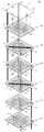
도 1은 본 발명의 실시예 1에 따른 편향기 일체형 전극 구조체를 이용한 RED장치의 분해사시도이다.
도 2는 도 1에서 유체의 흐름을 나타내는 개략도이다.
도 3 내지 도 5는 실시예1에서 전극 구조체의 변형예이다.
도 6a 내지 도 6h는 편향기의 변형예이다.1 is an exploded perspective view of an RED device using a deflector integrated electrode structure according to a first embodiment of the present invention.
Fig. 2 is a schematic view showing the flow of fluid in Fig. 1; Fig.
Figs. 3 to 5 are modification examples of the electrode structure in Embodiment 1. Fig.
6A to 6H are modification examples of the deflector.
이하, 본 발명을 바람직한 실시예를 첨부한 도면을 참조하여 설명하기로 한다. 하기의 각 도면의 구성 요소들에 참조 부호를 부가함에 있어서, 동일한 구성 요소들에 한해서는 비록 다른 도면상에 표시되더라도 가능한 한 동일한 부호를 가지도록 하며, 본 발명의 요지를 불필요하게 흐릴 수 있다고 판단되는 공지 기능 및 구성에 대한 상세한 설명은 생략한다.DETAILED DESCRIPTION OF THE PREFERRED EMBODIMENTS Hereinafter, preferred embodiments of the present invention will be described with reference to the accompanying drawings. In the drawings, the same reference numerals are used to designate the same or similar components, and the same reference numerals will be used to designate the same or similar components. Detailed descriptions of known functions and configurations are omitted.
도 1에서는 편향기 일체형 전극 구조체를 이용하여 역전기투석 발전(RED)장치(100)를 도시한다. 상기 RED장치(100)는 다른 장치로 변형하는 것도 가능하다.1, a reverse electrodialysis (RED)
상기 RED장치(100)는 기본적으로 상하부에 전극 구조체를 가지며, 이 전극 구조체 사이에 편향기 일체형 분리막이 위치한다.The
상기 편향기 일체형 분리막은 복수개가 적층된다. 이 때, 내부에 흐르는 유체를 구분하기 위하여 하나 이상의 제1교환막(130,150)과 하나 이상의 제2교환막(140,160)이 교대로 적층되어 이루어진다. 상기 제1교환막(130,150)과 상기 제2교환막(140,160) 중 일방은 양이온 교환막이고, 타방은 음이온 교환막이며 이는 필요에 따라 선택할 수 있다.A plurality of deflector integrated separators are laminated. At this time, one or more
또, 제1교환막의 개수와 제2교환막의 개수는 본 발명의 실시예에서는 동일하게 표현하였지만, 다르게 이루어질 수도 있다.In addition, the number of the first exchange film and the number of the second exchange film are expressed in the same manner in the embodiment of the present invention, but may be different.
상기 제1교환막(130,150)과 상기 제2교환막(140,160)의 각각의 테두리에는 간격을 유지할 수 있는 개스킷(136,146,156,166)이 형성된다. 상기 개스킷(136,146,156,166)은 분리막의 적층시 유체의 누수를 방지하는 역할도 수행한다. 상기 개스킷(136,146,156,166)의 위치는 모서리에 위치하는 것으로 제한되지는 않지만, 바람직하게는 최외측으로 배치하여 유체의 체류공간을 증대시킨다. 상기 개스킷(136,146,156,166)은 일체형 또는 분리형으로 이루어질 수 있으며, 일체형이 좀 더 바람직하다. 일체형의 개스킷(136,146,156,166)은 프린터에 의해 경화잉크(예를 들어, UV잉크)를 분사하고 경화시키는 것을 반복하는 것에 의해 형성될 수 있다.
상기 제1교환막(130,150)과 상기 제2교환막(140,160) 내부의 유체는 서로 섞이지 않도록 구성된다. 따라서 상기 제1교환막(130,150)과 상기 제2교환막(140,160)에는 유체를 바이패스시키는 한 쌍의 바이패스관(131,133,142,144,151,153,164)과 유체를 내부로 공급 또는 배출시키는 한 쌍의 연결홀(132,134,141,143,154,163)이 형성된다.The fluids in the first exchange membranes (130, 150) and the second exchange membranes (140, 160) are configured not to be mixed with each other. Accordingly, a pair of
상기 바이패스관(131,133,142,144,151,153,164)과 상기 연결홀(132,134,141,143,154,163)의 위치의 제한은 없으나, 유체의 체류시간을 늘리기 위하여 상기 제1교환막(130,150)과 상기 제2교환막(140,160)의 가장자리에 위치시키는 것이 바람직하다. 또한, 도 1 및 도 2에 도시된 바와 같이, 상기 바이패스관(131,133,142,144,151,153,164)과 상기 연결홀(132,134,141,143,154,163)을 서로 대향되도록 배치하는 것이 동일한 구조로 막을 90도 돌려사용하므로 제작상 유리하다.Although there is no limitation on the positions of the
그리고, 상기 개스킷(126,136,146,156,166)에 의해 한정되는 영역에는 편향기(125,135,145,155,165)가 형성된다. 실시예1에서 편향기(125,135,145,155,165)의 역할은 도 3에 도시된 바와 같이 유체의 이동을 방해하여 난류를 발생시키는 것이다. 이 때, 상기 편향기(125,135,145,155,165)는 상기 개스킷(126,136,146,156,166)의 높이와 같거나 이보다 작게 형성된다. 또는 편향기 대신 기존 직조형 스페이서를 사용해도 무관하다.
이러한 난류의 발생은 유선을 변화시킬 뿐 아니라, 교환막을 통한 투과도를 향상시킨다.This turbulence not only changes the streamline but also improves the permeability through the exchange membrane.
상술한 바와 같이 구성되는 편향기 일체형 분리막의 상하측에 전극구조체가 배치된다.The electrode structure is disposed on the upper and lower sides of the separator-integrated separation membrane constructed as described above.
상기 전극구조체는 상측의 전극구조체와 같이 전극분리막(120)이 추가로 구비되거나, 하측의 전극구조체와 같이 전극분리막 없이 그 상부에 배치되는 편향기 일체형 분리막을 공유하는 것도 가능 하지만, 적합하게는 전극분리막 없이 편향기 일체형 전극 구조체가 상/하부에 동시에 사용된다.The electrode structure may further include an
먼저, 하측의 전극구조체에 대해서 설명한다.First, the lower electrode structure will be described.
상기 하측의 전극구조체(170)는 전극플레이트(177)와, 상기 전극플레이트(170)의 테두리에 형성되는 개스킷(176)과, 상기 전극플레이트(177)의 표면에 형성되는 편향기(175)를 포함하고, 상기 전극플레이트(177)에는 상기 개스킷(176)과 상기 전극플레이트(177)에 한정되는 공간을 흐르는 전극유체가 공급 및 배출되는 전극유체공급홀(178)과 전극유체배출홀(179)이 형성되며, 염분차를 가진 제1유체와 제2유체가 유통되는 바이패스관(173,174)이 설치된다.The
상기 편향기(175)의 높이는 개스킷(176)의 높이와 같거나 작게 형성될 수 있다. 상기 편향기(175)와 상기 개스킷(176)의 역할은 상술한 바와 같다. 따라서 상기 하측의 전극구조체(170)는 도 2에 도시된 바와 같이 전극유체가 흐르게 된다. 상기 전극유체는 RED장치에서 린스로 사용되는 공지된 전기화학반응을 할 수 있는 전해질 액체를 사용할 수 있다.The height of the
다음으로, 상측의 전극구조체(120)에 대해서 설명한다. 상기 전극구조체(120)는 전극분리막(127)과, 상기 전극분리막(127)의 테두리에 형성되는 개스킷(126)과, 상기 개스킷(126)에 부착되어 상기 전극분리막(127)에 대하여 이격되어 설치되는 전극플레이트(117)와, 상기 전극플레이트(117)의 표면 또는 상기 전극분리막(127)의 표면에 형성되는 편향기(125)를 포함하고, 상기 전극플레이트(117)에는 상기 개스킷(126)과 상기 전극플레이트(117)에 한정되는 공간을 흐르는 전극유체가 공급 및 배출되는 전극유체공급홀(118)과 전극유체배출홀(119)이 형성되며, 염분차를 가지는 제1유체와 제2유체가 유통되는 바이패스관(121,122)이 설치된다.Next, the
그리고 상기 전극플레이트(117)에는 상기 바이패스관(121,122)과 연통되는 바이패스홀(111,112)가 형성된다.The
상측의 전극구조체(120)는 기본적으로 전극분리막(127)을 포함하는 것을 제외하고는 하측의 전극구조체(170)와 동일하다. 상기 하측의 전극구조체(170)는 그 바로 위에 오는 분리막(160)을 공유하여 내부공간을 한정하게 된다.The
따라서, 상기 전극유체는 상기 전극구조체(120,170)의 내부에서만 존재하고, 제1유체와 제2유체는 상기 교환막(130,140,150,160)을 통해 유통하게 된다. 상기 제1유체와 제2유체는 상술한 바와 같이 염분차를 가지는 액체로 이루어질 수 있다. 또한, 제 1유체는 순환형으로 구성될 수 있으며, 상측의 전극 구조체의 전극유체공급홀(118)을 통해 들어간 유체는 전극유체배출홀(119)를 통해 나온 후 하측 전극 구조체의 전극유체공급홀(178)을 통해 유입된 후 전극유체배출홀(179)을 통해 나온 후 다시 상측 전극 구조체의 전극유체공급홀(118)에 연결되어 사용될 수 있다.Accordingly, the electrode fluid exists only in the
도 2는 전극유체공급홀(178) 바로 옆에 배열되어 있는 편향기(175)가 유체 흐름에 영향을 주는 도식도이다.FIG. 2 is a schematic diagram in which a
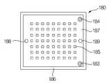
도 3 내지 도 5는 전극구조체의 변형예이다. 여기서는 전극분리막이 포함되지 않는 형상만을 도시하였으나, 상술한 바와 같이 전극분리막이 포함되는 것도 가능하다. 도 3a 및 도 3b는 편향기(185)의 높이가 개스킷(186)의 높이와 같은 전극구조체(180)에 대해서 도시하고 있다. 따라서 유체는 편향기(185)의 주위를 통해서만 이동하게 된다.Figs. 3 to 5 are modifications of the electrode structure. Although only the shape not including the electrode separation membrane is shown here, it is also possible to include the electrode separation membrane as described above. Figures 3a and 3b illustrate the
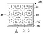
도 4는 서로 다른 직경의 편향기(395,399)를 가지는 전극구조체(390)에 대해서 도시하고 있다. 따라서 유체의 난류유동을 더욱 활발하게 할 수 있다.4 shows an
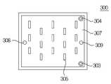
도 5는 편향기(305)가 일정피치로 이루어진 편향기열을 복수로 하여 배치되고, 이웃하는 편향기(305)의 열은 동일한 피치이지만 이웃하는 열의 편향기(305) 사이로 이동하는 유체를 간섭하도록 배치되는 전극구조체(300)에 대해서 도시하고 있다. 또한, 편향기의 구조를 구형이 아닌 다른 형태의 제작도 가능하다. 따라서 유체의 난류유동의 다른 형태를 나타낼 수 있다.5 is a schematic view showing a state in which the
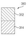
도 6a 내지 도 6h는 다양한 편향기(310,320,330,340,350,360,370,380)에 대해서 도시하고 있다. 도 6a의 편향기(310)는 2개의 서로 다른 제1세그먼트(312)와 제2세그먼트(314)가 높이방향으로 적층되어 이루어진다. 상기 제1세그먼트(312)와 상기 제2세그먼트(314)는 물리적 성질 또는 화학적 성질이 다를 수 있다. 물리적 성질이 다른 경우는, 표면거칠기가 다르거나 공극이 존부(存否)하는 등을 고려할 수 있다. 화학적 성질이 다른 경우는 서로 다른 촉매가 코팅되는 것을 고려할 수 있다.6A-6H illustrate
도 6b는 3가지의 서로 다른 세그먼트(322,324,326)로 이루어진 편향기(320)를 도시한다. 상기 세그먼트(322,324,326)는 물리적 성질 또는 화학적 성질이 다를 수 있다.6B shows a
도 6c는 제1세그먼트(332)의 측면 및 상단면을 제2세그먼트(324)가 감싼 형태의 편향기(330)를 도시한다.6C shows a
도 6d는 편향기바디(342)의 외주면에 고리형상의 돌기(344)가 형성된 편향기(320)를 도시한다.6D shows a
도 6e는 편향기바디(352)의 외주면에 복수의 돌기(354)가 형성된 편향기(320)를 도시한다.6E shows a
도 6f는 제1세그먼트(362)의 주위 전체를 제2세그먼트(364)가 감싼 형태의 편향기(360)를 도시한다.FIG. 6F shows a
도 6g는 2개의 서로 다른 제1세그먼트(372)와 제2세그먼트(374)가 폭방향으로 적층되어 이루어지는 편향기(370)를 도시한다.6G shows a
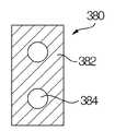
도 6h는 편향기바디(382)에 관통홀(384)이 형성된 편향기(380)가 도시된다.6H shows a
상기와 같이, 본 발명의 바람직한 실시예를 참조하여 설명하였지만 해당 기술 분야의 숙련된 당업자라면 하기의 특허청구범위에 기재된 본 발명의 사상 및 영역으로부터 벗어나지 않는 범위 내에서 본 발명을 다양하게 수정 및 변경시킬 수 있음을 이해할 수 있을 것이다.
While the present invention has been particularly shown and described with reference to exemplary embodiments thereof, it will be understood by those skilled in the art that various changes and modifications may be made without departing from the spirit and scope of the invention as defined in the appended claims. It can be understood that
100: RED장치
111,112: 바이패스홀
117,177: 전극플레이트
118,178: 전극유체공급홀
119,179: 전극유체배출홀
120,170,180,300,390: 전극구조체
127,177,187,307,397: 전극분리막
130,150: 제1교환막
140,160: 제2교환막
121,122,131,133,142,144,151,153,164,173,174,183,184,303,304,393,394: 바이패스관
132,134,141,143154,163,178: 연결홀
125,135,145,155,165,175,185,305,310,320,330,340,350,360,370,380,395,399: 편향기
126,136,146,156,166,176,186,306,396: 개스킷
127,137,147,157,167: 막본체
312,314,322,324,326,332,334,362,364: 세그먼트
342,352: 편향기바디
344,354: 돌기100: RED device
111, 112: Bypass hole
117, 177:
118, 178: electrode fluid supply hole
119, 179: electrode fluid discharge hole
120, 170, 180, 300,
127, 177, 187, 307, 397:
130, 150:
140, 160: second exchange membrane
143, 144, 151, 153, 164, 173, 174, 183, 184, 303, 304, 393, 394:
132, 134, 141, 143154, 163, 178:
125, 135, 145, 155, 165, 175, 185, 305, 310, 320, 330, 340, 350, 360,
126, 136, 146, 156, 166, 176, 186, 306, 396:
127, 137, 147, 157,
312, 314, 322, 324, 326, 332, 334, 362, 364:
342,352: Deflector body
344, 354:
Claims (16)
Translated fromKorean상기 전극플레이트의 테두리에 형성되는 개스킷; 및
상기 전극플레이트의 표면에 형성되는 편향기를 포함하고,
상기 전극플레이트에는 상기 개스킷과 상기 전극플레이트에 한정되는 공간을 흐르는 전극유체가 공급 및 배출되는 전극유체공급홀과 전극유체배출홀이 형성되며, 제1유체와 제2유체가 유통되는 바이패스관이 설치되는 것을 특징으로 하는 편향기 일체형 전극 구조체.
An electrode plate;
A gasket formed at an edge of the electrode plate; And
And a deflector formed on a surface of the electrode plate,
Wherein the electrode plate is provided with an electrode fluid supply hole and an electrode fluid discharge hole through which the electrode fluid flowing in the space defined by the gasket and the electrode plate is supplied and discharged and a bypass pipe through which the first fluid and the second fluid are communicated, Wherein the electrode assembly is provided with an electrode assembly.
상기 전극플레이트의 테두리에 형성되는 개스킷;
상기 개스킷에 부착되어 상기 전극플레이트에 대하여 이격되어 설치되는 전극분리막;
상기 전극플레이트의 표면 또는 상기 전극분리막의 표면에 형성되는 편향기;
를 포함하고,
상기 전극플레이트에는 상기 개스킷과 상기 전극플레이트에 한정되는 공간을 흐르는 전극유체가 공급 및 배출되는 전극유체공급홀과 전극유체배출홀이 형성되며, 제2유체와 제3유체가 유통되는 바이패스관이 설치되는 것을 특징으로 하는 편향기 일체형 전극 구조체.
An electrode plate;
A gasket formed at an edge of the electrode plate;
An electrode separator attached to the gasket and spaced apart from the electrode plate;
A deflector formed on a surface of the electrode plate or a surface of the electrode separator;
Lt; / RTI >
Wherein the electrode plate is provided with an electrode fluid supply hole and an electrode fluid discharge hole through which the electrode fluid flowing in the space defined by the gasket and the electrode plate is supplied and discharged and a bypass pipe through which the second fluid and the third fluid are flowed, Wherein the electrode assembly is provided with an electrode assembly.
The deflector-integrated electrode structure according to claim 1 or 2, wherein the deflector is formed lower than the height of the gasket.
The deflector-integrated electrode structure according to claim 1 or 2, wherein the deflector is formed to have the same height as the gasket.
The deflector-integrated electrode structure according to claim 1 or 2, wherein the surface of the deflector is coated with a catalyst.
The deflector-integrated electrode structure according to claim 1 or 2, wherein the deflector comprises at least two deflectors having different cross-sectional shapes.
The deflector-integrated electrode structure according to claim 1 or 2, wherein a plurality of deflectors are arranged at a constant pitch to form a deflector array, and a plurality of deflector arrays are arranged at constant intervals.
8. The deflector integrated electrode structure according to claim 7, wherein adjacent deflector rows have a pitch phase difference.
The deflector-integrated electrode structure according to claim 1 or 2, wherein the deflector comprises two or more different segments.
The deflector-integrated electrode structure according to claim 9, wherein the plurality of segments are stacked in the height direction of the deflector.
The deflector-integrated electrode structure according to claim 9, wherein the plurality of segments are disposed to adhere in the width direction of the deflector.
10. The deflector integrated electrode structure according to claim 9, wherein the plurality of segments surround the outer surface of one segment by another segment.
The deflector-integrated electrode structure according to claim 9, wherein the plurality of segments are in a state in which another segment is inserted into one segment.
The deflector-integrated electrode structure according to claim 1 or 2, wherein the deflector has a protrusion formed on the outer surface of the deflector body.
15. The deflector integrated electrode structure according to claim 14, wherein the projections are in the form of a ring.
Priority Applications (1)
| Application Number | Priority Date | Filing Date | Title |
|---|---|---|---|
| KR1020130031649AKR20140116724A (en) | 2013-03-25 | 2013-03-25 | Electrode structure integrated with deflector |
Applications Claiming Priority (1)
| Application Number | Priority Date | Filing Date | Title |
|---|---|---|---|
| KR1020130031649AKR20140116724A (en) | 2013-03-25 | 2013-03-25 | Electrode structure integrated with deflector |
Publications (1)
| Publication Number | Publication Date |
|---|---|
| KR20140116724Atrue KR20140116724A (en) | 2014-10-06 |
Family
ID=51990404
Family Applications (1)
| Application Number | Title | Priority Date | Filing Date |
|---|---|---|---|
| KR1020130031649ACeasedKR20140116724A (en) | 2013-03-25 | 2013-03-25 | Electrode structure integrated with deflector |
Country Status (1)
| Country | Link |
|---|---|
| KR (1) | KR20140116724A (en) |
Cited By (6)
| Publication number | Priority date | Publication date | Assignee | Title |
|---|---|---|---|---|
| US11502323B1 (en) | 2022-05-09 | 2022-11-15 | Rahul S Nana | Reverse electrodialysis cell and methods of use thereof |
| US11502322B1 (en) | 2022-05-09 | 2022-11-15 | Rahul S Nana | Reverse electrodialysis cell with heat pump |
| KR20230138607A (en)* | 2022-03-24 | 2023-10-05 | 창원대학교 산학협력단 | Module for flow-electrode capacitive deionization and power generation |
| US11855324B1 (en) | 2022-11-15 | 2023-12-26 | Rahul S. Nana | Reverse electrodialysis or pressure-retarded osmosis cell with heat pump |
| US12040517B2 (en) | 2022-11-15 | 2024-07-16 | Rahul S. Nana | Reverse electrodialysis or pressure-retarded osmosis cell and methods of use thereof |
| US12341228B2 (en) | 2022-11-15 | 2025-06-24 | Rahul S. Nana | Reverse electrodialysis or pressure-retarded osmosis cell and methods of use thereof |
- 2013
- 2013-03-25KRKR1020130031649Apatent/KR20140116724A/ennot_activeCeased
Cited By (11)
| Publication number | Priority date | Publication date | Assignee | Title |
|---|---|---|---|---|
| KR20230138607A (en)* | 2022-03-24 | 2023-10-05 | 창원대학교 산학협력단 | Module for flow-electrode capacitive deionization and power generation |
| US11502323B1 (en) | 2022-05-09 | 2022-11-15 | Rahul S Nana | Reverse electrodialysis cell and methods of use thereof |
| US11502322B1 (en) | 2022-05-09 | 2022-11-15 | Rahul S Nana | Reverse electrodialysis cell with heat pump |
| US11563229B1 (en) | 2022-05-09 | 2023-01-24 | Rahul S Nana | Reverse electrodialysis cell with heat pump |
| US11611099B1 (en) | 2022-05-09 | 2023-03-21 | Rahul S Nana | Reverse electrodialysis cell and methods of use thereof |
| US11699803B1 (en) | 2022-05-09 | 2023-07-11 | Rahul S Nana | Reverse electrodialysis cell with heat pump |
| US12107308B2 (en) | 2022-05-09 | 2024-10-01 | Rahul S Nana | Reverse electrodialysis cell and methods of use thereof |
| US11855324B1 (en) | 2022-11-15 | 2023-12-26 | Rahul S. Nana | Reverse electrodialysis or pressure-retarded osmosis cell with heat pump |
| US12040517B2 (en) | 2022-11-15 | 2024-07-16 | Rahul S. Nana | Reverse electrodialysis or pressure-retarded osmosis cell and methods of use thereof |
| US12341228B2 (en) | 2022-11-15 | 2025-06-24 | Rahul S. Nana | Reverse electrodialysis or pressure-retarded osmosis cell and methods of use thereof |
| US12374711B2 (en) | 2022-11-15 | 2025-07-29 | Rahul S. Nana | Reverse electrodialysis or pressure-retarded osmosis cell with heat pump |
Similar Documents
| Publication | Publication Date | Title |
|---|---|---|
| KR20140116724A (en) | Electrode structure integrated with deflector | |
| CN102648547B (en) | Humidifier for fuel cell | |
| US9577242B2 (en) | Internal header flow divider for uniform electrolyte distribution | |
| US10199663B2 (en) | Cell structure for fuel cell stack | |
| KR101875520B1 (en) | Bipolar plate and electrochemical cell comprising such a bipolar plate | |
| US8444833B2 (en) | Device for electrochemical water preparation | |
| CN114277395A (en) | Novel electrode unit with guide wedge-shaped structure, electrolytic unit and application | |
| KR101621033B1 (en) | Capacitive flow electrode device with ion-exchanged current collector | |
| CN219315103U (en) | Main polar plate, electrode plate and electrolytic tank | |
| US11437631B2 (en) | Fuel cell separator and power generation cell | |
| CN114182278A (en) | Electrode unit, electrolysis unit and application of a novel guiding rhombus structure | |
| KR101147198B1 (en) | Capacitive deionization device | |
| KR101667110B1 (en) | Electrochemical unit cell | |
| US10780399B2 (en) | Membrane stack and method for making the same | |
| JP5603894B2 (en) | Fuel cell | |
| CN202893204U (en) | Support diversion disc and separating-filtering membrane column device | |
| JP2011507210A (en) | Flow field plate for use in a fuel cell stack | |
| CN204007245U (en) | A kind of plate type heat exchanger | |
| CN112290045B (en) | Battery unit | |
| KR101574268B1 (en) | Membrane integrated with deflector | |
| RU2626463C1 (en) | Bipolar plate of fuel round-shaped cell | |
| KR20150003094A (en) | Flow-electrode capacitive deionizaion apparatus using ion exchange membranes | |
| CN110639368B (en) | A disc tube type membrane module guide plate | |
| CN111224126B (en) | Flow frame for flow battery and application of flow frame | |
| US20240117509A1 (en) | Electrolysis plate for hydrogen procution and method for producing an electrolysis plate |
Legal Events
| Date | Code | Title | Description |
|---|---|---|---|
| A201 | Request for examination | ||
| PA0109 | Patent application | Patent event code:PA01091R01D Comment text:Patent Application Patent event date:20130325 | |
| PA0201 | Request for examination | ||
| E902 | Notification of reason for refusal | ||
| PE0902 | Notice of grounds for rejection | Comment text:Notification of reason for refusal Patent event date:20140627 Patent event code:PE09021S01D | |
| E601 | Decision to refuse application | ||
| PE0601 | Decision on rejection of patent | Patent event date:20140930 Comment text:Decision to Refuse Application Patent event code:PE06012S01D Patent event date:20140627 Comment text:Notification of reason for refusal Patent event code:PE06011S01I | |
| PG1501 | Laying open of application |