KR20140114253A - LED lighting apparatus - Google Patents
LED lighting apparatusDownload PDFInfo
- Publication number
- KR20140114253A KR20140114253AKR1020130098918AKR20130098918AKR20140114253AKR 20140114253 AKR20140114253 AKR 20140114253AKR 1020130098918 AKR1020130098918 AKR 1020130098918AKR 20130098918 AKR20130098918 AKR 20130098918AKR 20140114253 AKR20140114253 AKR 20140114253A
- Authority
- KR
- South Korea
- Prior art keywords
- led
- terminal
- metal plate
- metal plates
- electrode
- Prior art date
- Legal status (The legal status is an assumption and is not a legal conclusion. Google has not performed a legal analysis and makes no representation as to the accuracy of the status listed.)
- Pending
Links
- 229910052751metalInorganic materials0.000claimsabstractdescription156
- 239000002184metalSubstances0.000claimsabstractdescription156
- 238000000034methodMethods0.000claimsdescription12
- 239000000758substrateSubstances0.000claimsdescription7
- 230000008878couplingEffects0.000claimsdescription4
- 238000010168coupling processMethods0.000claimsdescription4
- 238000005859coupling reactionMethods0.000claimsdescription4
- 230000003449preventive effectEffects0.000claimsdescription3
- 239000012811non-conductive materialSubstances0.000claimsdescription2
- 230000002265preventionEffects0.000claims1
- 238000005286illuminationMethods0.000abstractdescription6
- 230000000694effectsEffects0.000description16
- 238000005452bendingMethods0.000description7
- RYGMFSIKBFXOCR-UHFFFAOYSA-NCopperChemical compound[Cu]RYGMFSIKBFXOCR-UHFFFAOYSA-N0.000description5
- 238000010586diagramMethods0.000description5
- 229910052802copperInorganic materials0.000description4
- 239000010949copperSubstances0.000description4
- 239000011810insulating materialSubstances0.000description4
- 239000000463materialSubstances0.000description4
- 229910000679solderInorganic materials0.000description4
- 229920003002synthetic resinPolymers0.000description4
- 239000000057synthetic resinSubstances0.000description4
- 239000010410layerSubstances0.000description3
- 229910000881Cu alloyInorganic materials0.000description2
- 101001045744Sus scrofa Hepatocyte nuclear factor 1-betaProteins0.000description2
- 229910052782aluminiumInorganic materials0.000description2
- XAGFODPZIPBFFR-UHFFFAOYSA-NaluminiumChemical compound[Al]XAGFODPZIPBFFR-UHFFFAOYSA-N0.000description2
- 238000004519manufacturing processMethods0.000description2
- 230000004048modificationEffects0.000description2
- 238000012986modificationMethods0.000description2
- 229910000838Al alloyInorganic materials0.000description1
- 239000012790adhesive layerSubstances0.000description1
- 238000009792diffusion processMethods0.000description1
- 238000010292electrical insulationMethods0.000description1
- 230000017525heat dissipationEffects0.000description1
- 238000009413insulationMethods0.000description1
- 230000003287optical effectEffects0.000description1
- 229910052709silverInorganic materials0.000description1
- 239000004332silverSubstances0.000description1
Images


Classifications
- F—MECHANICAL ENGINEERING; LIGHTING; HEATING; WEAPONS; BLASTING
- F21—LIGHTING
- F21S—NON-PORTABLE LIGHTING DEVICES; SYSTEMS THEREOF; VEHICLE LIGHTING DEVICES SPECIALLY ADAPTED FOR VEHICLE EXTERIORS
- F21S41/00—Illuminating devices specially adapted for vehicle exteriors, e.g. headlamps
- F21S41/10—Illuminating devices specially adapted for vehicle exteriors, e.g. headlamps characterised by the light source
- F21S41/19—Attachment of light sources or lamp holders
- F21S41/192—Details of lamp holders, terminals or connectors
- F—MECHANICAL ENGINEERING; LIGHTING; HEATING; WEAPONS; BLASTING
- F21—LIGHTING
- F21K—NON-ELECTRIC LIGHT SOURCES USING LUMINESCENCE; LIGHT SOURCES USING ELECTROCHEMILUMINESCENCE; LIGHT SOURCES USING CHARGES OF COMBUSTIBLE MATERIAL; LIGHT SOURCES USING SEMICONDUCTOR DEVICES AS LIGHT-GENERATING ELEMENTS; LIGHT SOURCES NOT OTHERWISE PROVIDED FOR
- F21K9/00—Light sources using semiconductor devices as light-generating elements, e.g. using light-emitting diodes [LED] or lasers
- F21K9/20—Light sources comprising attachment means
- F21K9/23—Retrofit light sources for lighting devices with a single fitting for each light source, e.g. for substitution of incandescent lamps with bayonet or threaded fittings
- F21K9/235—Details of bases or caps, i.e. the parts that connect the light source to a fitting; Arrangement of components within bases or caps
- F—MECHANICAL ENGINEERING; LIGHTING; HEATING; WEAPONS; BLASTING
- F21—LIGHTING
- F21S—NON-PORTABLE LIGHTING DEVICES; SYSTEMS THEREOF; VEHICLE LIGHTING DEVICES SPECIALLY ADAPTED FOR VEHICLE EXTERIORS
- F21S45/00—Arrangements within vehicle lighting devices specially adapted for vehicle exteriors, for purposes other than emission or distribution of light
- F21S45/40—Cooling of lighting devices
- F21S45/47—Passive cooling, e.g. using fins, thermal conductive elements or openings
- F—MECHANICAL ENGINEERING; LIGHTING; HEATING; WEAPONS; BLASTING
- F21—LIGHTING
- F21K—NON-ELECTRIC LIGHT SOURCES USING LUMINESCENCE; LIGHT SOURCES USING ELECTROCHEMILUMINESCENCE; LIGHT SOURCES USING CHARGES OF COMBUSTIBLE MATERIAL; LIGHT SOURCES USING SEMICONDUCTOR DEVICES AS LIGHT-GENERATING ELEMENTS; LIGHT SOURCES NOT OTHERWISE PROVIDED FOR
- F21K9/00—Light sources using semiconductor devices as light-generating elements, e.g. using light-emitting diodes [LED] or lasers
- F21K9/20—Light sources comprising attachment means
- F21K9/23—Retrofit light sources for lighting devices with a single fitting for each light source, e.g. for substitution of incandescent lamps with bayonet or threaded fittings
- F21K9/232—Retrofit light sources for lighting devices with a single fitting for each light source, e.g. for substitution of incandescent lamps with bayonet or threaded fittings specially adapted for generating an essentially omnidirectional light distribution, e.g. with a glass bulb
- F—MECHANICAL ENGINEERING; LIGHTING; HEATING; WEAPONS; BLASTING
- F21—LIGHTING
- F21K—NON-ELECTRIC LIGHT SOURCES USING LUMINESCENCE; LIGHT SOURCES USING ELECTROCHEMILUMINESCENCE; LIGHT SOURCES USING CHARGES OF COMBUSTIBLE MATERIAL; LIGHT SOURCES USING SEMICONDUCTOR DEVICES AS LIGHT-GENERATING ELEMENTS; LIGHT SOURCES NOT OTHERWISE PROVIDED FOR
- F21K9/00—Light sources using semiconductor devices as light-generating elements, e.g. using light-emitting diodes [LED] or lasers
- F21K9/20—Light sources comprising attachment means
- F21K9/23—Retrofit light sources for lighting devices with a single fitting for each light source, e.g. for substitution of incandescent lamps with bayonet or threaded fittings
- F21K9/237—Details of housings or cases, i.e. the parts between the light-generating element and the bases; Arrangement of components within housings or cases
- F—MECHANICAL ENGINEERING; LIGHTING; HEATING; WEAPONS; BLASTING
- F21—LIGHTING
- F21K—NON-ELECTRIC LIGHT SOURCES USING LUMINESCENCE; LIGHT SOURCES USING ELECTROCHEMILUMINESCENCE; LIGHT SOURCES USING CHARGES OF COMBUSTIBLE MATERIAL; LIGHT SOURCES USING SEMICONDUCTOR DEVICES AS LIGHT-GENERATING ELEMENTS; LIGHT SOURCES NOT OTHERWISE PROVIDED FOR
- F21K9/00—Light sources using semiconductor devices as light-generating elements, e.g. using light-emitting diodes [LED] or lasers
- F21K9/20—Light sources comprising attachment means
- F21K9/27—Retrofit light sources for lighting devices with two fittings for each light source, e.g. for substitution of fluorescent tubes
- F—MECHANICAL ENGINEERING; LIGHTING; HEATING; WEAPONS; BLASTING
- F21—LIGHTING
- F21S—NON-PORTABLE LIGHTING DEVICES; SYSTEMS THEREOF; VEHICLE LIGHTING DEVICES SPECIALLY ADAPTED FOR VEHICLE EXTERIORS
- F21S41/00—Illuminating devices specially adapted for vehicle exteriors, e.g. headlamps
- F21S41/10—Illuminating devices specially adapted for vehicle exteriors, e.g. headlamps characterised by the light source
- F21S41/14—Illuminating devices specially adapted for vehicle exteriors, e.g. headlamps characterised by the light source characterised by the type of light source
- F21S41/141—Light emitting diodes [LED]
- F21S41/147—Light emitting diodes [LED] the main emission direction of the LED being angled to the optical axis of the illuminating device
- F21S41/148—Light emitting diodes [LED] the main emission direction of the LED being angled to the optical axis of the illuminating device the main emission direction of the LED being perpendicular to the optical axis
- F—MECHANICAL ENGINEERING; LIGHTING; HEATING; WEAPONS; BLASTING
- F21—LIGHTING
- F21S—NON-PORTABLE LIGHTING DEVICES; SYSTEMS THEREOF; VEHICLE LIGHTING DEVICES SPECIALLY ADAPTED FOR VEHICLE EXTERIORS
- F21S41/00—Illuminating devices specially adapted for vehicle exteriors, e.g. headlamps
- F21S41/60—Illuminating devices specially adapted for vehicle exteriors, e.g. headlamps characterised by a variable light distribution
- F21S41/65—Illuminating devices specially adapted for vehicle exteriors, e.g. headlamps characterised by a variable light distribution by acting on light sources
- F21S41/663—Illuminating devices specially adapted for vehicle exteriors, e.g. headlamps characterised by a variable light distribution by acting on light sources by switching light sources
- F—MECHANICAL ENGINEERING; LIGHTING; HEATING; WEAPONS; BLASTING
- F21—LIGHTING
- F21S—NON-PORTABLE LIGHTING DEVICES; SYSTEMS THEREOF; VEHICLE LIGHTING DEVICES SPECIALLY ADAPTED FOR VEHICLE EXTERIORS
- F21S43/00—Signalling devices specially adapted for vehicle exteriors, e.g. brake lamps, direction indicator lights or reversing lights
- F21S43/10—Signalling devices specially adapted for vehicle exteriors, e.g. brake lamps, direction indicator lights or reversing lights characterised by the light source
- F21S43/13—Signalling devices specially adapted for vehicle exteriors, e.g. brake lamps, direction indicator lights or reversing lights characterised by the light source characterised by the type of light source
- F21S43/14—Light emitting diodes [LED]
- F—MECHANICAL ENGINEERING; LIGHTING; HEATING; WEAPONS; BLASTING
- F21—LIGHTING
- F21S—NON-PORTABLE LIGHTING DEVICES; SYSTEMS THEREOF; VEHICLE LIGHTING DEVICES SPECIALLY ADAPTED FOR VEHICLE EXTERIORS
- F21S43/00—Signalling devices specially adapted for vehicle exteriors, e.g. brake lamps, direction indicator lights or reversing lights
- F21S43/10—Signalling devices specially adapted for vehicle exteriors, e.g. brake lamps, direction indicator lights or reversing lights characterised by the light source
- F21S43/19—Attachment of light sources or lamp holders
- F21S43/195—Details of lamp holders, terminals or connectors
- F—MECHANICAL ENGINEERING; LIGHTING; HEATING; WEAPONS; BLASTING
- F21—LIGHTING
- F21S—NON-PORTABLE LIGHTING DEVICES; SYSTEMS THEREOF; VEHICLE LIGHTING DEVICES SPECIALLY ADAPTED FOR VEHICLE EXTERIORS
- F21S45/00—Arrangements within vehicle lighting devices specially adapted for vehicle exteriors, for purposes other than emission or distribution of light
- F21S45/10—Protection of lighting devices
- F—MECHANICAL ENGINEERING; LIGHTING; HEATING; WEAPONS; BLASTING
- F21—LIGHTING
- F21V—FUNCTIONAL FEATURES OR DETAILS OF LIGHTING DEVICES OR SYSTEMS THEREOF; STRUCTURAL COMBINATIONS OF LIGHTING DEVICES WITH OTHER ARTICLES, NOT OTHERWISE PROVIDED FOR
- F21V19/00—Fastening of light sources or lamp holders
- F21V19/001—Fastening of light sources or lamp holders the light sources being semiconductors devices, e.g. LEDs
- F—MECHANICAL ENGINEERING; LIGHTING; HEATING; WEAPONS; BLASTING
- F21—LIGHTING
- F21V—FUNCTIONAL FEATURES OR DETAILS OF LIGHTING DEVICES OR SYSTEMS THEREOF; STRUCTURAL COMBINATIONS OF LIGHTING DEVICES WITH OTHER ARTICLES, NOT OTHERWISE PROVIDED FOR
- F21V19/00—Fastening of light sources or lamp holders
- F21V19/006—Fastening of light sources or lamp holders of point-like light sources, e.g. incandescent or halogen lamps, with screw-threaded or bayonet base
- F—MECHANICAL ENGINEERING; LIGHTING; HEATING; WEAPONS; BLASTING
- F21—LIGHTING
- F21V—FUNCTIONAL FEATURES OR DETAILS OF LIGHTING DEVICES OR SYSTEMS THEREOF; STRUCTURAL COMBINATIONS OF LIGHTING DEVICES WITH OTHER ARTICLES, NOT OTHERWISE PROVIDED FOR
- F21V29/00—Protecting lighting devices from thermal damage; Cooling or heating arrangements specially adapted for lighting devices or systems
- F21V29/50—Cooling arrangements
- F21V29/70—Cooling arrangements characterised by passive heat-dissipating elements, e.g. heat-sinks
- F—MECHANICAL ENGINEERING; LIGHTING; HEATING; WEAPONS; BLASTING
- F21—LIGHTING
- F21V—FUNCTIONAL FEATURES OR DETAILS OF LIGHTING DEVICES OR SYSTEMS THEREOF; STRUCTURAL COMBINATIONS OF LIGHTING DEVICES WITH OTHER ARTICLES, NOT OTHERWISE PROVIDED FOR
- F21V29/00—Protecting lighting devices from thermal damage; Cooling or heating arrangements specially adapted for lighting devices or systems
- F21V29/85—Protecting lighting devices from thermal damage; Cooling or heating arrangements specially adapted for lighting devices or systems characterised by the material
- F21V29/89—Metals
- F—MECHANICAL ENGINEERING; LIGHTING; HEATING; WEAPONS; BLASTING
- F21—LIGHTING
- F21S—NON-PORTABLE LIGHTING DEVICES; SYSTEMS THEREOF; VEHICLE LIGHTING DEVICES SPECIALLY ADAPTED FOR VEHICLE EXTERIORS
- F21S45/00—Arrangements within vehicle lighting devices specially adapted for vehicle exteriors, for purposes other than emission or distribution of light
- F21S45/40—Cooling of lighting devices
- F21S45/42—Forced cooling
- F21S45/43—Forced cooling using gas
- F—MECHANICAL ENGINEERING; LIGHTING; HEATING; WEAPONS; BLASTING
- F21—LIGHTING
- F21W—INDEXING SCHEME ASSOCIATED WITH SUBCLASSES F21K, F21L, F21S and F21V, RELATING TO USES OR APPLICATIONS OF LIGHTING DEVICES OR SYSTEMS
- F21W2102/00—Exterior vehicle lighting devices for illuminating purposes
- F—MECHANICAL ENGINEERING; LIGHTING; HEATING; WEAPONS; BLASTING
- F21—LIGHTING
- F21Y—INDEXING SCHEME ASSOCIATED WITH SUBCLASSES F21K, F21L, F21S and F21V, RELATING TO THE FORM OR THE KIND OF THE LIGHT SOURCES OR OF THE COLOUR OF THE LIGHT EMITTED
- F21Y2101/00—Point-like light sources
- F—MECHANICAL ENGINEERING; LIGHTING; HEATING; WEAPONS; BLASTING
- F21—LIGHTING
- F21Y—INDEXING SCHEME ASSOCIATED WITH SUBCLASSES F21K, F21L, F21S and F21V, RELATING TO THE FORM OR THE KIND OF THE LIGHT SOURCES OR OF THE COLOUR OF THE LIGHT EMITTED
- F21Y2107/00—Light sources with three-dimensionally disposed light-generating elements
- F21Y2107/30—Light sources with three-dimensionally disposed light-generating elements on the outer surface of cylindrical surfaces, e.g. rod-shaped supports having a circular or a polygonal cross section
- F—MECHANICAL ENGINEERING; LIGHTING; HEATING; WEAPONS; BLASTING
- F21—LIGHTING
- F21Y—INDEXING SCHEME ASSOCIATED WITH SUBCLASSES F21K, F21L, F21S and F21V, RELATING TO THE FORM OR THE KIND OF THE LIGHT SOURCES OR OF THE COLOUR OF THE LIGHT EMITTED
- F21Y2107/00—Light sources with three-dimensionally disposed light-generating elements
- F21Y2107/40—Light sources with three-dimensionally disposed light-generating elements on the sides of polyhedrons, e.g. cubes or pyramids
- F—MECHANICAL ENGINEERING; LIGHTING; HEATING; WEAPONS; BLASTING
- F21—LIGHTING
- F21Y—INDEXING SCHEME ASSOCIATED WITH SUBCLASSES F21K, F21L, F21S and F21V, RELATING TO THE FORM OR THE KIND OF THE LIGHT SOURCES OR OF THE COLOUR OF THE LIGHT EMITTED
- F21Y2115/00—Light-generating elements of semiconductor light sources
- F21Y2115/10—Light-emitting diodes [LED]
Landscapes
- Engineering & Computer Science (AREA)
- General Engineering & Computer Science (AREA)
- Physics & Mathematics (AREA)
- Microelectronics & Electronic Packaging (AREA)
- Optics & Photonics (AREA)
- Fastening Of Light Sources Or Lamp Holders (AREA)
- Non-Portable Lighting Devices Or Systems Thereof (AREA)
- Arrangement Of Elements, Cooling, Sealing, Or The Like Of Lighting Devices (AREA)
Abstract
Description
Translated fromKorean본 발명은 엘이디조명기구에 관한 것으로서, 보다 상세하게는 엘이디소자를 이용하여 조명하는 엘이디조명기구에 관한 것이다.BACKGROUND OF THE
일반적으로 조명장치는 실내 또는 실외를 조명하거나 교통 신호등, 경고등 등의 알림수단 등으로 널리 사용되고 있다.Generally, the lighting apparatus is widely used for illuminating the interior or the exterior of the room, as a means of notifying a traffic light, a warning light, and the like.
주로 조명장치로서 전류를 공급받으면 고온으로 가열되면서 빛을 발산하는 필라멘트가 이용되고 있으며, 근래에는 소비전력이 적고, 빛의 밝기가 우수하며, 수명이 긴 엘이디(LED)를 이용한 조명장치가 주목을 받고 있다.As an illumination device, a filament that emits light while being heated to a high temperature when supplied with current is used. Recently, a lighting device using an LED (LED) having low power consumption, excellent brightness, .
그러나, 엘이디는 빛의 직진성이 강하여 빛의 확산 특성이 낮고, 측면 조도가 약하기 때문에 현 실정에서는 기존의 필라멘트를 이용한 조명장치를 대체하기에는 미흡하다.However, since the LED has a strong linearity of light, the light diffusing property is low and the side illumination is weak, it is not enough to replace the lighting device using the existing filament at present.
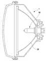
도 1 및 도 2는, 자동차에 벌브형 전구(10)를 가지는 종래의 조명기구(1)를 도시한 도면으로서, 도시된 바와 같이, 종래의 조명기구(1)는 전조등, 안개등과 같이 기능구현에 최적화된 반사부재(20)를 가진다.1 and 2 are diagrams showing a
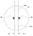
특히 상기 반사부재(20)는, 그 반사면이 도 2에 도시된 자동차에 벌브형 전구(10)의 발광부분(11), 즉 필라멘트의 위치, 예를 들면 조명기구(1) 내에 결합되는 소켓(12)으로부터의 거리(l)에 대응되어 최적화되어 설계됨이 일반적이다.Particularly, the reflecting
그런데 위와 같은 구조를 가지는 종래의 조명기구(1)에서 엘이디 조명기구로 대체하고자 하는 경우 거의 전방향으로 조사되는 종래의 벌브형 전구(10)와는 달리 일방향으로 진진성을 가지는 엘이디의 광특성으로 인하여 종래의 조명기구(1)에서 반사부재(20)의 재활용이 불가능하며 별도로 설계된 반사부재를 필요로 한다.However, in case of replacing the
이에 벌브형 전구를 구비한 종래의 조명기구를 엘이디 조명기구로 교체하는 경우 반사부재의 재설계 등 교체비용이 높아 엘이디 조명기구의 활용효과 및 확산의 장애요인으로 작용하는 문제점이 있다.If a conventional lighting fixture having a bulb type bulb is replaced with an LED lighting fixture, there is a problem in that the replacement cost such as redesign of the reflective member is high and serves as an obstacle to the utilization effect and diffusion of the LED lighting fixture.
본 발명의 목적은, 벌브형 전구를 사용하는 자동차의 전조등, 안개등과 같이 기존의 조명조립체에서 별도의 구조 변경없이 기존 벌브형 전구를 대체할 수 있는 엘이디조명기구를 제공하는 데 있다.SUMMARY OF THE INVENTION It is an object of the present invention to provide an LED lighting fixture that can replace an existing bulb-type bulb in a conventional lighting assembly such as a headlight or a fog lamp of an automobile using a bulb-type bulb without any structural change.
본 발명의 다른 목적은, 벌브형 전구에 최적화된 반사갓 등을 구비한 종래의 조명설비에서 별도의 구조 변경없이 벌브형 전구와 유사한 조명효과를 가질 수 있는 엘이디조명기구를 제공하는 데 있다.It is another object of the present invention to provide an LED lighting fixture which can have a similar lighting effect to a bulb-type bulb without any structural change in a conventional lighting fixture having a reflector optimized for a bulb-type bulb.
본 발명의 다른 목적은, 벌브형 전구에서 2개 이상의 광원에 의하여 최적화된 반사갓 등을 구비한 종래의 조명설비, 특히 자동차 조명장치에서 벌브형 전구에 의하여 위치되는 광원에 대응되어 엘이디소자들을 위치시킴으로써 별도의 구조 변경없이 벌브형 전구와 유사한 조명효과를 가질 수 있는 엘이디조명기구를 제공하는 데 있다.It is another object of the present invention to provide a lighting fixture, such as a lighting fixture having a reflector optimized by two or more light sources in a bulb-type bulb, in particular in an automotive lighting fixture, by positioning the LED elements in correspondence with a light source positioned by a bulb- And it is an object of the present invention to provide an LED light fixture which can have a similar lighting effect to a bulb-type light bulb without any structural change.
본 발명은 상기와 같은 본 발명의 목적을 달성하기 위하여 창출된 것으로서, 본 발명은 엘이디조명기구가 설치될 구조물과의 결합을 위한 소켓부(230)와; 일단이 상기 소켓부(230)에 결합되며 서로 대향되는 표면의 반대면에 제1엘이디소자(120a)가 각각 설치된 한 쌍의 제1금속플레이트(110-5)들과; 상기 한 쌍의 제1금속플레이트(110-5)들 사이에서 상기 한 쌍의 제1금속플레이트(110-5)들과 평행을 이루며 일단이 상기 소켓부(230)에 결합되며 서로 대향되는 표면의 반대면에 제2엘이디소자(120b)가 각각 설치된 한 쌍의 제2금속플레이트(110-6)들과; 상기 한 쌍의 제2금속플레이트(110-6)들 사이에서 상기 한 쌍의 제2금속플레이트(110-6)들과 평행을 이루며 일단이 상기 소켓부(230)에 결합되고, 상기 제2금속플레이트(110-6)과 수직을 이루도록 절곡된 절곡면부(113)을 가지며, 상기 절곡면부(113)에 제3엘이디소자(120c)가 설치된 하나 이상의 제3금속플레이트(110-6)와; 상기 제1 내지 제3금속플레이트들 간의 간격을 유지하도록 상기 제1 내지 제3금속플레이트들의 타단들이 결합되는 간격유지부재(280)를 포함하는 것을 특징으로 하는 엘이디조명기구를 개시한다.The present invention has been made in order to achieve the above-mentioned object of the present invention, and it is an object of the present invention to provide a lighting device, A pair of first metal plates 110-5, one end of which is coupled to the
상기 제1 내지 제3엘이디소자(120a, 120b, 120c)는, 제1전극 및 제2전극 중 어느 하나만 상기 제1 내지 제3금속플레이트들 각각과 열전도가 가능하도록 결합될 수 있다.The first to
상기 제1금속플레이트(110-5)는 내측에 위치된 상기 제2금속플레이트(110-6)에 설치된 제2엘이디소자(120b)가 외측으로 노출될 수 있도록 절개된 절개부(310)가 형성될 수 있다.The first metal plate 110-5 is formed with an
상기 제1엘이디소자(120a) 및 상기 제2엘이디소자(120b)는, 상기 소켓부(280)에 대한 거리가 다르게 설치될 수 있다.The
상기 엘이디조명기구는, 하나의 전구에 의하여 상향등 및 하향등이 가능하도록 2개의 필라멘트를 가지는 전구를 대신하여 자동차 전조등에 설치되며, 상기 제1엘이디소자(120a) 및 상기 제2엘이디소자(120b) 중 어느 하나는 상향등에 대응되는 필라멘트의 위치에 위치되며, 다른 하나는 하향등에 대응되는 필라멘트의 위치에 위치될 수 있다.The LED lighting apparatus is installed in a vehicle headlamp in place of a bulb having two filaments so that the lamp can be upside down or downward by a single bulb, and the
상기 소켓부(230)에 설치되어 상기 제1엘이디소자(120a) 및 상기 제2엘이디소자(120b) 중 어느 하나 및 상기 제3엘이디소자(120c)를 직렬 또는 병렬로 연결하는 제1단자(237) 및 제2단자(238)와; 상기 소켓부(230)에 설치되어 상기 제2단자(238)와, 상기 제1엘이디소자(120a) 및 상기 제2엘이디소자(120b) 중 나머지 하나를 직렬로 연결하는 제3단자(239)를 추가로 포함하여, 상기 제2단자(238)를 공유함과 아울러 상기 제1단자(237) 및 제3단자(239) 중 적어도 어느 하나에 전원을 연결될 수 있다.A
상기 제1 내지 제3금속플레이트들은, 각각 상기 제1 내지 제3엘이디소자(120a, 120b, 120c) 각각의 제1전극 및 제2전극 중 어느 하나만 열전도가 가능하도록 나머지 전극인 열전도가 이루어지지 않는 비접촉전극에 대응되는 위치에 그 접촉을 방지하기 위한 접촉방지수단이 형성될 수 있다.In the first through third metal plates, the first electrode and the third electrode of the
상기 접촉방지수단은, 상기 제1 내지 제3금속플레이트들 각각에 형성된 관통공 또는 절개부일 수 있다.The contact preventing means may be a through hole or a cut-out portion formed in each of the first to third metal plates.
상기 비접촉전극은, 다른 엘이디소자의 단자와의 연결 또는 전원공급선과 연결을 위한 전원연결선이 상기 관통공 또는 절개부를 통하여 연결될 수 있다.The noncontact electrode may be connected to a terminal of another LED element or a power supply line for connection to a power supply line through the through hole or the cutout portion.
상기 접촉방지수단은, 상기 제1 내지 제3금속플레이트들 각각에 형성된 절연부재일 수 있다.The contact preventing means may be an insulating member formed on each of the first to third metal plates.
상기 소켓부는, 상기 구조물에 탈착가능하게 결합되며 비전도성 물질로 이루어진 본체와; 상기 본체에 설치되어 상기 구조물에 설치된 연결단자와의 전기적 연결을 위한 단자연결부와; 상기 엘이디소자와 상기 단자연결부와 전기적으로 연결시키는 소자전원공급부를 포함할 수 있다.The socket portion includes a body detachably coupled to the structure and made of a nonconductive material; A terminal connection portion provided in the main body for electrical connection with a connection terminal provided in the structure; And an element power supply unit for electrically connecting the LED element and the terminal connection unit.
상기 소자전원공급부는, 상기 단자연결부와 전기적으로 연결된 복수의 단자부가 형성되고, 상기 본체와 결합되어 상기 금속플레이트를 지지하는 지지기판부와, 상기 엘이디소자 및 상기 단자부를 연결하는 하나 이상의 전선을 포함할 수 있다.The device power supply unit may include a support substrate portion formed with a plurality of terminal portions electrically connected to the terminal connection portion and coupled to the main body to support the metal plate, and at least one wire connecting the LED device and the terminal portion can do.
본 발명에 따른 엘이디조명기구는, 하나 이상의 금속플레이트에 엘이디소자를 설치함으로써 엘이디소자에서 발생된 열을 금속플레이트를 전달하여 방열하는 구조를 가짐으로써 구조가 간단하면서 효율적으로 방열할 수 있는 이점이 있다.The LED lighting apparatus according to the present invention has an advantage that a structure can be easily and effectively radiated by providing a structure in which the heat generated from the LED elements is transferred to the metal plate by radiating heat by providing an LED element on one or more metal plates .
또한 본 발명에 따른 엘이디조명기구는, 서로 마주보는 면의 반대면인 외면에 각각 엘이디소자가 결합된 한 쌍의 금속플레이트로 구성됨으로써 벌브형 전구와 유사한 광조사효과를 가짐으로써 벌브형 전구가 사용되는 기존의 조명장치에서 벌브형 전구를 대체함으로써 엘이디조명기구의 활용도를 극대화할 수 있는 이점이 있다.Further, the LED lighting apparatus according to the present invention comprises a pair of metal plates each having an LED element coupled to an outer surface, which is a surface opposite to a surface facing each other, so that the bulb type bulb is used It is possible to maximize the utilization of the LED lighting apparatus by replacing the bulb type bulb in the conventional lighting apparatus.
특히 벌브형 전구를 사용하는 기존 조명시설에는 반사갓을 구비함을 특징으로 하는데 이때 반사갓은 벌브형 전구 특히 벌브형 전구의 발광부분에 대응하여 최적화되는바, 본 발명에 따른 엘이디조명기구는, 하나 이상의 금속플레이트에 엘이디소자를 설치하여 구성되는바 엘이디소자의 위치를 기존의 벌브형 전구의 발광부분에 대응되는 위치에 위치시킴으로써 벌브형 전구와 유사한 광조사효과를 가짐으로써 벌브형 전구가 사용되는 기존의 조명장치에서 벌브형 전구를 대체함으로써 엘이디조명기구의 활용도를 극대화할 수 있는 이점이 있다.Particularly, a conventional lighting facility using a bulb-type bulb is characterized by having a reflector, wherein the reflector is optimized in correspondence with the bulb-type bulb, in particular, the bulb-type bulb, wherein the LED- The position of the bar-shaped element formed by arranging the LED element on the metal plate is positioned at a position corresponding to the light-emitting portion of the bulb-type bulb, so that the bulb-type bulb has a light irradiation effect similar to that of the bulb- There is an advantage that the utilization of the LED lighting apparatus can be maximized by replacing the bulb type bulb in the lighting apparatus.
구체적인 예로서, 본 발명에 따른 엘이디조명기구는, 자동차용 전조등, 안개등, 방향지시등 등에 사용되는 경우 다름과 같은 이점이 있다.As a specific example, the LED lighting apparatus according to the present invention is advantageous in that it is different when it is used in a headlight for a car, a fog lamp, a turn signal lamp, or the like.
먼저 엘이디조명기구는 벌브형 전구와는 다른 조명 특성이 있는바, 자동차용 전조등, 안개등, 방향지시등과 같이 특수한 조명효과를 요구하는 조명기구로 사용되는 경우 종래에는 벌브형 전구를 구비하는 조명기구 중 반사갓의 설계를 변경하여야하는 문제점이 있다.First, the LED lighting apparatus has different lighting characteristics from the bulb type bulb. When the LED lighting apparatus is used as a lighting apparatus requiring special lighting effects such as a headlight for a car, a fog lamp, and a turn signal lamp, There is a problem that the design of the reflector must be changed.
그런데 본 발명에 따른 엘이디조명기구는, 기존의 벌브형 전구의 발광부분에 대응되는 위치에 위치시킴으로써 벌브형 전구와 유사한 광조사효과를 가짐으로써 벌브형 전구가 사용되는 기존의 조명장치에서 벌브형 전구를 대체함으로써 엘이디조명기구의 활용도를 극대화할 수 있는 이점이 있다.In the conventional lighting apparatus in which the bulb type bulb is used by having the illumination effect similar to that of the bulb type bulb by positioning the LED lighting apparatus according to the present invention at a position corresponding to the light emitting portion of the existing bulb type bulb, It is possible to maximize the utilization of the LED lighting apparatus.
더 나아가 다양한 조명효과, 예를 들면 위치, 즉 광원의 위치가 다른 2개의 필라멘트를 구비하여 하나의 벌브형 전구에 의하여 상향등 및 하향등 동시 구현이 가능한 기존의 조명장치에서 각 광원의 위치에 대응하여 엘이디소자를 위치시킴으로써 벌브형 전구가 사용되는 기존의 조명장치에서 벌브형 전구를 대체함으로써 엘이디조명기구의 활용도를 극대화할 수 있는 이점이 있다.In addition, in a conventional lighting apparatus in which a plurality of filaments having different positions of light sources, for example, positions of the light sources are provided, and one bulb-type bulb can simultaneously implement the upward and downward lights, There is an advantage that the utilization of the LED lighting apparatus can be maximized by replacing the bulb type bulb in the existing lighting apparatus in which the bulb type bulb is used by positioning the LED element.
도 1은, 벌브형 전구를 가지는 종래의 조명기구로서, 구체적으로 자동차용 전조등을 보여주는 개념도이다.
도 2는, 도 1의 자동차용 전조등에 사용되는 벌브형 전구의 일예를 보여주는 측면도이다.
도 3a는, 본 발명의 제1실시예에 따른 엘이디조명기구를 보여주는 사시도이다.
도 3b는, 도 1의 엘이디조명장치의 일부를 보여주는 분해도이다.
도 4a는, 도 3a의 엘이디조명기구의 측면도이다.
도 4b는, 도 3a의 엘이디조명기구의 평면도이다.
도 5는, 도 3a에서 Ⅴ-Ⅴ방향의 단면도이다.
도 6은, 도 5의 변형례를 보여주는 Ⅴ-Ⅴ방향의 단면도이다.
도 7은, 본 발명의 제2실시예에 따른 엘이디조명기구를 보여주는 측면도이다.
도 8은, 도 7의 엘이디조명기구의 평면도이다.
도 9는, 본 발명의 제3실시예에 따른 엘이디조명기구를 보여주는 측면도이다.
도 10은, 도 9의 엘이디조명기구의 평면도이다.
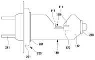
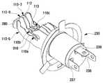
도 11은, 본 발명의 제4실시예에 따른 엘이디조명기구를 보여주는 사시도이다.
도 12는, 도 11의 엘이디조명기구를 보여주는 분해사시도이다.
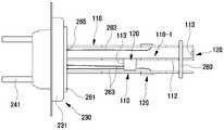
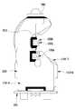
도 13a는, 도 11의 엘이디조명기구의 평면도, 도 13b는, 도 11의 엘이디조명기구의 측면도이다.
도 14는, 도 11의 엘이디조명기구의 등가회로도의 일예를 보여주는 개념도이다.
도 15는, 벌브형 전구가 설치되는 종래의 조명기구에 도 11의 엘이디조명기구가 설치된 예를 보여주는 개념도이다.Fig. 1 is a conceptual diagram showing a conventional lighting apparatus having a bulb-type bulb, specifically a headlamp for a vehicle.
Fig. 2 is a side view showing an example of a bulb-type bulb used in the automotive headlight of Fig. 1. Fig.
3A is a perspective view showing an LED lighting apparatus according to a first embodiment of the present invention.
3B is an exploded view showing a part of the LED illumination device of FIG.
Fig. 4A is a side view of the LED lighting apparatus of Fig. 3A. Fig.
Fig. 4B is a plan view of the LED lighting device of Fig. 3A. Fig.
5 is a cross-sectional view taken along the line V-V in Fig.
6 is a cross-sectional view in the V-V direction showing the modification of Fig.
7 is a side view showing an LED lighting device according to a second embodiment of the present invention.
Fig. 8 is a plan view of the LED lighting device of Fig. 7. Fig.
9 is a side view showing an LED lighting device according to a third embodiment of the present invention.
10 is a plan view of the LED lighting device of Fig.
11 is a perspective view showing an LED lighting device according to a fourth embodiment of the present invention.
12 is an exploded perspective view showing the LED lighting device of Fig.
Fig. 13A is a plan view of the LED lighting device of Fig. 11, and Fig. 13B is a side view of the LED lighting device of Fig.
Fig. 14 is a conceptual diagram showing an example of an equivalent circuit diagram of the LED lighting device of Fig. 11; Fig.
Fig. 15 is a conceptual diagram showing an example in which the LED lighting device of Fig. 11 is installed in a conventional lighting device in which a bulb type bulb is installed.
이하 본 발명에 따른 엘이디조명기구에 관하여 첨부된 도면을 참조하여 상세히 설명하면 다음과 같다.Hereinafter, an LED lighting apparatus according to the present invention will be described in detail with reference to the accompanying drawings.
본 발명에 따른 엘이디조명기구는, 도 3a 내지 도 10에 도시된 바와 같이, 하나 이상의 금속플레이트(110)와; 금속플레이트(110)의 표면에 설치된 하나 이상의 엘이디소자(120)를 포함한다.As shown in FIGS. 3A to 10, the LED lighting apparatus according to the present invention includes at least one
상기 금속플레이트(110)는, 엘이디소자(120)가 설치되고 지지될 수 있도록 플레이트 형상을 가지며 열방출이 용이하도록 알루미늄, 알루미늄합금, 구리, 구리합금, SUS 등 열전도성이 높을 재질이면 어떠한 재질도 가능하다.The
특히 상기 금속플레이트(110)는, 가공성을 고려하여 구리 또는 구리합금이 보다 바람직하다.Particularly, the
또한 상기 금속플레이트(110)의 두께는, 구조적 강성 및 제조상의 한계가 없다면 가능하면 최소화되는 것이 바람직하다.It is also desirable that the thickness of the
특히 상기 금속플레이트(110)의 두께는, 0.01㎜~0.5㎜인 것이 바람직하며, 0.1㎜~0.4㎜인 것이 더욱 바람직하다.In particular, the thickness of the
그리고 상기 금속플레이트(110)는, 그 표면에 엘이디소자(120) 등에서 조사되는 광의 반사효과를 높이기 위하여 은과 같이 반사율이 높은 물질이 코팅될 수 있다.The
또한 상기 금속플레이트(110)는, 그 표면의 적어도 일부에 절연특성을 부여하기 위하여 절연물질이 코팅될 수 있다.In addition, the
또한 상기 금속플레이트(110)는, 엘이디소자(120)에 대한 전원연결을 위한 배선이 부착되거나, 프린팅될 수 있다.Also, the
또한 상기 금속플레이트(110)는, 회로가 패턴으로 형성될 수 있다.Also, the
또한 상기 금속플레이트(110)는, 엘이디소자(120)가 설치될 수 있는 FPCB 등과 같은 보드가 결합될 수 있다.The
또한 상기 금속플레이트(110)는, 제조과정, 즉 엘이디소자(120)와의 결합 등을 위하여 땜납이 땜납영역 이외의 영역으로 벗어나는 것을 방지하기 위한 합성수지물질이 인쇄될 수 있다.In addition, the
한편 상기 금속플레이트(110)는, 엘이디소자(120)의 열방출효과, 복수개로 구성된 경우 엘이디소자(120)의 광조사효과 등을 고려하여 다양한 형상을 가질 수 있다.The
구체적으로 상기 금속플레이트(110)는, 도 3a 및 도 3b에 도시된 바와 같이, 평판 형상을 가지며 예로서 벌브와 유사한 평면형상을 가질 수 있다.Specifically, the
또한 상기 금속플레이트(110)는, 도 7 내지 도 10에 도시된 바와 같이, 엘이디소자(120)가 설치된 설치면부(112)와, 설치면부(112)와 절곡되어 연장되는 절곡면부(113)를 포함하는 절곡금속플레이트(110-1)로 구성될 수 있다.7 to 10, the
상기 절곡금속플레이트(110-1)는 금속플레이트(110)가 복수개로 구성되고 엘이디소자(120)의 광조사효과를 극대화하기 위하여 소켓부(230)와 같이 지지구조물에 결합되는 절곡면부(113)와 일체로 형성되는 설치면부(112)를 포함함을 특징으로 한다.The bending metal plate 110-1 is composed of a plurality of
이때 상기 설치면부(112)는, 엘이디소자(120)의 광조사방향을 결정하는 부분으로서 엘이디소자(120)가 설치된 면의 법선이 엘이디소자(120)의 광조사방향과 평행하도록 형성된다.The mounting
그리고 상기 절곡면부(113)는 설치면부(112)와 일체로 이루어 지지하는 부분으로서 인접하는 금속플레이트(110)와 평행(가장 바람직), 수직, 경사를 이루어 소켓부(230)와 같이 지지구조물에 결합되는 구성으로서 다양한 구성이 가능한다.The folded
한편 상기 금속플레이트(110)는, 복수개로 구성됨이 바람직하며, 복수개로 구성된 경우 복수의 금속플레이트(110)들은, 적어도 일부가 엘이디소자(120)가 설치된 면이 서로 평행을 이루거나, 수직을 이루거나, 경사를 이루도록 설치될 수 있다.The plurality of
상기와 같은 금속플레이트(110)는, 1) 엘이디소자(120)를 직접적으로 견고하게 지지-참고로 FPCB의 경우 그 자체로 엘이디소자(120)에 대한 지지가 불가하며, 열전도율이 낮은 합성수지재 재질을 가져 열방출효과가 현저히 낮다. 그리고 메탈 PCB인 경우 인쇄회로기판과 금속층(알루미늄)과의 절연을 위한 절연층의 존재, 구체적으로 엘이디소자(120), 땜납, 구리배선, 접착층, 절연층, 접착층 및 알루미늄 금속층 순으로 열이 전달되고 열방출시 병목현상이 있어 열방출효과가 낮으며, 전체적으로 두꺼운 문제점이 있음-하는 역할의 수행이 가능하며, 2) 엘이디소자(120)의 제1단자(121) 및 제2단자(122) 중 어느 하나와 직접 연결됨으로써 엘이디소자(120)에 대한 전원공급을 위한 전기전도체 역할의 수행이 가능하며, 3) 엘이디소자(120)로부터 열을 전달받아 방열하는 방열부재 역할, 특히 엘이디소자(120)의 제1단자(121), 제2단자(122), 히트슬러그(124) 중 적어도 어느 하나와 납땜 등에 의하여 연결됨으로써 열방출이 효과적으로 이루어질 수 있으며, 4) 간단한 구조임에도 불구하고 벌브형 전구의 발광부분(필라멘트)에 최적 위치에 위치시켜 기존 반사갓을 활용한 활용효과를 높일 수 있다.1) The
상기 엘이디소자(120)는, DC전원의 공급에 의하여 발광하는 엘이디소자로서, 백색광을 발광하는 백색엘이디소자, 황색광을 발광하는 황색엘이디소자, 청색엘이디소자, 적색엘이디소자, 녹색엘이디소자, "청색엘이디소자, 적색엘이디소자 및 녹색엘이디소자"가 하나의 칩으로 형성된 삼색 엘이디칩 등 다양한 엘이디소자가 사용될 수 있다.The
일예로서, 상기 엘이디소자(120)는, 도 5에 도시된 바와 같이, +단자 및 -단자인 제1전극(121) 및 제2전극(122)를 포함할 수 있다.For example, the
또한 상기 엘이디소자(120)는, 도 5에 도시된 바와 같이, +단자 및 -단자인 제1전극(121) 및 제2전극(122)이외에 열방출을 위한 히트슬러그(124, heat slug)를 추가로 포함할 수 있다.5, the
상기 히트슬러그(124)는, 엘이디소자에서 발생되는 열을 방출하기 위하여 설치된 구성으로서 그 구조에 따라서 제1전극(121) 및 제2전극(122)와 일체로 구성될 수 있다.The
한편 상기 엘이디소자(120)는, 금속플레이트(110)와의 결합시 제1전극(121) 및 제2전극(122) 중 어느 하나만 금속플레이트(110)와 열전도가 가능하도록 금속플레이트(110)와 결합될 수 있다.The
또한 상기 엘이디소자(120)는, 히트슬러그(124)를 추가로 포함하는 경우, 히트슬러그(124)만 금속플레이트(120)와 열전도가 가능하도록 금속플레이트(110)에 결합될 수 있다.In addition, when the
이때 상기 엘이디소자(120)는, 도 3a 내지 도 5에 도시된 바와 같이, 금속플레이트(110)에 직접 결합될 수 있다.At this time, the
이 경우, 상기 엘이디소자(120)의 제1전극(121) 및 제2전극(122) 중 어느 하나만 금속플레이트(110)와 통전될 필요가 있는바 금속플레이트(110)와 통전되지 않는 전극은 금속플레이트(110)에 전기적으로 절연되도록 설치된다.In this case, only one of the first electrode 121 and the
구체적으로, 상기 금속플레이트(110)는, 엘이디소자(120)의 제1전극(121) 및 제2전극(122) 중 어느 하나만 열전도가 가능하도록 나머지 전극인 열전도가 이루어지지 않는 비접촉전극에 대응되는 위치에 그 접촉을 방지하기 위한 접촉방지수단(111)이 형성될 수 있다.Specifically, the
그리고 상기 접촉방지수단(111)은, 도 5에 도시된 바와 같이, 금속플레이트(110)에 형성된 관통공으로, 또는 도 7 및 도 9에 도시된 바와 같이 절개부로 구성될 수 있다.The contact preventing means 111 may be formed as a through hole formed in the
이때 상기 비접촉전극은, 도 5에 도시된 바와 같이, 다른 엘이디소자의 단자와의 연결 또는 전원공급선과 연결을 위한 전원연결선(250)이 관통공을 통하여 연결될 수 있다.As shown in FIG. 5, the contactless electrode may be connected to a terminal of another LED device or a
상기 전원연결선(250)은, 후술하는 제1실시예에서 각 엘이디소자(110)와 연결됨으로써 평행하게 배치된 금속플레이트(110) 사이의 간격을 유지시키는데 활용될 수 있다. 여기서 상기 평행하게 배치된 금속플레이트(110)들 사이의 간격은 후술하는 간격유지부재(280)에 의하여 유지될 수 있음은 물론이다.The power
또한 상기 접촉방지수단(111)은, 다른 예로서, 도 6에 도시된 바와 같이, 금속플레이트(110)에 형성된 절연부재(111)로 구성될 수 있다.As another example, the contact preventing means 111 may be constituted by an insulating
상기 절연부재는, 엘이디소자(120) 및 금속플레이트(110) 간의 전기적 절연을 위한 구성으로서 금속플레이트(110) 표면 상에 코팅된 절연물질, 부착된 절연테이프 등 다양하게 구성될 수 있다.The insulating member may be configured in various forms such as an insulating material coated on the surface of the
한편 도 5의 예와는 달리 제1전극(121) 및 제2전극(122)와 전기적으로 절연된 히트슬러그(124)만 금속플레이트(120)와 열전도가 가능하도록 금속플레이트(110)에 결합된 경우, 엘이디소자(120)는 제1전극(121) 및 제2전극(122)는 금속플레이트(110)에 전기적으로 절연되도록 설치된다.5, only the
또한 도 5의 예와는 달리 상기 엘이디소자(120)는, 금속플레이트(110)에 직접 결합되는 대신에, 금속플레이트(110)에 결합되는 인쇄회로기판(미도시)에 장착될 수 있으며, 이 경우 인쇄회로기판은 엘이디소자(120)가 금속플레이트(110)에 직접 결합된 경우와 유사하게, 제1전극(121) 및 제2전극(122) 중 어느 하나가 금속플레이트(110)와 열전도가 가능하도록 금속플레이트(110)에 결합될 수 있다.5, the
한편 본 발명에 따른 엘이디조명기구는, 엘이디소자(120) 및 엘이디소자(120)가 결합된 금속플레이트(110)를 기본구조로 하며, 복수개로 구성됨으로써 금속플레이트(110)가 서로 평행하게 배치되거나, 일부가 서로 경사를 이루어 배치되는 등 여러 가지 배치 조합에 의하여 다양한 조명효과를 가지는 조명기구를 구성할 수 있다.Meanwhile, the LED lighting device according to the present invention has a basic structure of a
특히 본 발명에 따른 엘이디소자(120) 및 엘이디소자(120)가 결합된 금속플레이트(110)의 기본구조를 복수개로 구성하여 벌브형 전구와 같은 조명효과를 가지도록 구성될 수 있으며, 특히 벌브형 전구를 사용하는 자동차용 전조등, 안개등, 방향지시등과 같은 조명기구에 벌브형 전구를 대체함으로써 엘이디조명기구의 활용효과를 극대화할 수 있다.In particular, the
이하 본 발명에 따른 엘이디조명기구가 자동차용 전조등, 안개등, 방향지시등과 같은 조명기구에 사용되는 것을 예를 들어 설명한다.Hereinafter, the LED lighting apparatus according to the present invention will be described as being used in a lighting apparatus such as a headlight for a car, a fog lamp, and a turn signal lamp.
본 발명의 제1실시예에 따른 엘이디조명기구는, 도 3a 내지 도 5에 도시된 바와 같이, 엘이디소자(120) 및 엘이디소자(120)가 결합된 금속플레이트(110)의 기본구조로 하는 한편, 금속플레이트(110)는, 서로 평행하게 배치되며 서로 마주보는 면의 반대면에 하나 이상의 상기 엘이디소자(120)가 설치된 제1금속플레이트 및 제2금속플레이트를 포함하여 구성될 수 있다.3A and 5, the LED lighting apparatus according to the first embodiment of the present invention has a basic structure of a
그리고 상기 한 쌍의 금속플레이트(110)의 일단에는 엘이디조명기구가 설치될 구조물, 즉 자동차용 조명기구와의 결합을 위한 소켓부(230)가 결합될 수 있다.In addition, a
여기서 상기 금속플레이트(110)는, 소켓부(230)와 고정결합되거나 탈착가능하게 결합되는 등 다양한 방식에 의하여 결합될 수 있다.The
상기 소켓부(230)는, 엘이디조명기구가 설치될 구조물, 즉 자동차용 조명기구와의 결합을 위한 구성으로서 설치될 구조물과의 결합태양에 따라서 다양한 구성이 가능하다.The
일예로서, 상기 소켓부(230)는, 구조물에 탈착가능하게 결합되는 본체(231)와; 본체(231)에 설치되어 구조물에 설치된 연결단자(미도시)와의 전기적 연결을 위한 단자연결부(240)와; 엘이디소자(120)와 단자연결부(240)와 전기적으로 연결시키는 소자전원공급부(260)를 포함할 수 있다.For example, the
상기 본체(231)는, 엘이디조명기구를 구조물에 안정적으로 결합시키기 위한 구성으로서 하나 이상의 부재로 구성될 수 있으며, 절연물질 또는 금속 및 절연물질의 조합 등 다양한 구성이 가능하다.The
상기 단자연결부(240)는, 본체(231)에 설치되어 구조물에 설치된 연결단자(미도시)와의 전기적 연결을 위한 구성으로서 단자연결방식에 따라서 다양한 구성이 가능하며 경우에 따라서는 본체(231)와 일체로 구성될 수 있다.The
상기 소자전원공급부(260)는, 엘이디소자(120)와 단자연결부(240)와 전기적으로 연결시키는 구성으로서 단자연결부(240) 및 엘이디소자(120)와의 연결구조에 따라서 기판, 전선, 전도성부재 등 다양한 조합에 의한 구성이 가능하다.The element power supply unit 260 is electrically connected to the
예로서, 상기 소자전원공급부(260)는, 도 4a 및 도 4b에 도시된 바와 같이, 금속플레이트(110)와 결합되어 금속플레이트(110)를 지지하는 한편 단자연결부(240)와 결합되는 기판(261)과, 엘이디소자(120)에 전원을 공급하는 연결부분(262)를 포함하여 구성될 수 있다.4A and 4B, the device power supply unit 260 includes a substrate (not shown) coupled with the
여기서 금속플레이트(110)는, 엘이디소자(120)의 제1전극 및 제2전극 중 어느 하나와 전기적으로 연결될 수 있다.Here, the
상기 기판(261)은, 금속플레이트(110)를 지지하는 한편 단자연결부(240)와 결합되는 구성으로서 다양한 구성이 가능하며 금속플레이트(110) 중 적어도 하나의 돌출부(119)가 삽입되는 관통공(261a)이 형성되고 단자연결부(240)와 엘이디소자(120)와의 통전을 위한 회로패턴이 형성되는 등 다양한 구성이 가능하다.The
그리고 상기 기판(261)은, 소켓부(230)를 이루는 본체(231)의 일부 또는 전체를 구성할 수도 있다.The
상기 연결부분(262)은, 엘이디소자(120)에 전원을 공급하는 부분으로서, 도 4a 및 도 4b에 도시된 바와 같이, 땜납부분, 도 7 내지 도 10에 도시된 바와 같이, 전선 등 다양한 구성이 가능하다.The connecting
한편 상기 소자전원공급부(260)의 다른 구성으로서, 도 7 내지 도 10에 도시된 바와 같이, 단자연결부(240)와 전기적으로 연결된 복수의 단자부(265)가 형성되고, 본체(231)와 결합되어 금속플레이트(110)를 지지하는 기판(261)과, 엘이디소자(120) 및 단자부(265)를 연결하는 하나 이상의 전선(263)을 포함할 수 있다.7 to 10, a plurality of
여기서 상기 전선(263)은, 합성수지 내에 구리선들이 설치된 사용전선 이외에, 동선, 철선 등 전기전도성 부재이면 모두가 가능하다.Here, the
한편 상기 한 쌍의 금속플레이트(110)의 일단에는 엘이디조명기구가 설치될 구조물, 즉 자동차용 조명기구와의 결합을 위한 소켓부(230)가 결합될 때, 그 타단에는 한 쌍의 금속플레이트(110) 사이의 간격을 안정적을 유지할 수 있도록 하는 간격유지부재(280)가 추가로 설치될 수 있다.On the other hand, when a
상기 간격유지부재(280)는, 한 쌍의 금속플레이트(110) 사이의 간격을 안정적을 유지하는 구성으로서 합성수지, PCB와 같은 절연부재로서 금속플레이트(110)가 삽입될 수 있는 관통공(281)이 형성되어 금속플레이트(110)가 삽입됨으로써 한 쌍의 금속플레이트(110)와 고정결합될 수 있다.The
한편 본 발명의 제1실시예에 따른 엘이디조명기구에 있어서, 엘이디소자(120)의 배치 및 위치는, 대체될 조명기구의 벌브형 전구의 특성에 따라 달라질 수 있다.In the LED lighting apparatus according to the first embodiment of the present invention, the arrangement and position of the
구체적으로, 본 발명의 제1실시예에 따른 엘이디조명기구는, 벌브형 전구가 설치되는 자동차의 전조등, 안개등, 방향지시등 및 후미등 중 어느 하나에 설치되며, 엘이디소자(120)는, 도 4a에 도시된 바와 같이, 벌브형 전구가 자동차에 설치되었을 때 벌브형 전구의 발광부분, 즉 필라멘트의 위치에 대응되는 위치에 위치되도록 금속플레이트(110)에 결합될 수 있다.Specifically, the LED lighting apparatus according to the first embodiment of the present invention is installed in any one of a headlight, a fog lamp, a turn signal lamp, and a tail lamp of an automobile in which a bulb type bulb is installed, As shown, the bulb type bulb can be coupled to the
구체적으로 벌브형 전구에서 소켓부(12)로부터 발광부분(11)까지의 거리(l)에 대응되도록, 엘이디소자(120)는, 금속플레이트(110)에서 소켓부(230)로부터 거리(l)을 가지도록 설치될 수 있다.Specifically, the
한편, 본 발명에 따른 엘이디조명기구는, 벌브형 전구가 설치되는 자동차의 전조등, 안개등, 방향지시등 및 후미등 중 어느 하나에 설치될 때, 설치될 조명기구의 발광구조, 발광특성 등에 따라서 측면방향의 발광특성을 높이거나 전면 방향의 발광특성을 높일 필요가 있다.Meanwhile, when the LED lighting apparatus according to the present invention is installed in any one of a headlight, a fog lamp, a turn signal lamp and a tail lamp of an automobile in which a bulb type bulb is installed, It is necessary to increase the light emitting property or the light emitting property in the front direction.
이에 본 발명의 제2실시예 및 제3실시예에 따른 엘이디조명기구는, 제1실시예의 구성에 더하여, 도 7 내지 도 10에 도시된 바와 같이, 엘이디소자(120)가 설치된 설치면부(112)와, 설치면부(112)와 절곡되어 연장되는 절곡면부(113)를 포함하는 하나 이상의 절곡금속플레이트(110-1)를 포함할 수 있다.7 to 10, in addition to the configuration of the first embodiment, the LED lighting apparatus according to the second embodiment and the third embodiment of the present invention is provided with the mounting
이때 제2실시예로서, 상기 소켓부(230)와의 결합방향을 길이방향으로 할 때, 절곡금속플레이트(110-1)는, 도 7 및 도 8에 도시된 바와 같이, 그 설치면부(112)의 법선이 길이방향과 수직을 이루는, 즉 엘이디소자(120)의 발광면이 측면을 향하는, 하나 이상의 제1절곡금속플레이트를 포함할 수 있다.7 and 8, the bending metal plate 110-1 has a mounting
또한 제3실시예로서, 상기 소켓부(230)와의 결합방향을 길이방향으로 할 때, 절곡금속플레이트(110-1)는, 그 설치면부(112)의 법선이 길이방향과 평행을 이루는, 즉 엘이디소자(120)의 발광면이 전방을 향하는, 하나 이상의 제2절곡금속플레이트를 포함할 수 있다.In the third embodiment, when the direction of engagement with the
한편 상기 금속플레이트(110) 및 엘이디소자(120)는 복수로 구성될 때 그 등가회로는 각 엘이디소자(120)를 기준으로 직렬, 병렬, 직병렬 조합 등 다양한 등가회로의 구성이 가능하다.When the
여기서 상기 금속플레이트(110)는, 등가회로의 일부분 즉, 엘이디소자(120)의 제1전극 및 제2전극 중 어느 하나의 전극과 통전될 수 있다.The
한편 본 발명에 따른 엘이디조명기구는, 엘이디소자가 설치된 금속플레이트를 복수개로 구비하고 각 금속플레이트에 설치된 엘이디소자의 상대위치를 변화시켜 다양한 조명효과를 구현할 수 있다.Meanwhile, the LED lighting apparatus according to the present invention can realize various lighting effects by providing a plurality of metal plates provided with the LED elements and changing the relative positions of the LED elements installed on the respective metal plates.
이하 제4실시예에 따른 엘이디조명기구에 관하여 도 11 내지 도 15를 참조하여 설명하다. 여기서 제4실시예에 따른 엘이디조명기구는 금속플레이트의 배치 등 일부 구성에서 차이가 있으며 앞서 설명한 제1 내지 제3실시예에서의 구성과 동일하거나 유사한 구성은 편의상 그 설명을 생략한다.Hereinafter, an LED lighting device according to a fourth embodiment will be described with reference to Figs. 11 to 15. Fig. Here, the LED lighting apparatus according to the fourth embodiment differs in some configurations, such as the arrangement of metal plates, and the same or similar configurations as those in the first to third embodiments described above are omitted for the sake of convenience.
본 발명의 제4실시예에 따른 엘이디조명기구는, 도 11 내지 도 15에 도시된 바와 같이, 엘이디조명기구가 설치될 구조물과의 결합을 위한 소켓부(230)와; 일단이 소켓부(230)에 결합되며 서로 대향되는 표면의 반대면에 제1엘이디소자(120a)가 각각 설치된 한 쌍의 제1금속플레이트(110-5)들과; 한 쌍의 제1금속플레이트(110-5)들 사이에서 한 쌍의 제1금속플레이트(110-5)들과 평행을 이루며 일단이 소켓부(230)에 결합되며 서로 대향되는 표면의 반대면에 제2엘이디소자(120b)가 각각 설치된 한 쌍의 제2금속플레이트(110-6)들과; 한 쌍의 제2금속플레이트(110-6)들 사이에서 한 쌍의 제2금속플레이트(110-6)들과 평행을 이루며 일단이 소켓부(230)에 결합되고, 제2금속플레이트(110-6)과 수직을 이루도록 절곡된 절곡면부(113)을 가지며, 절곡면부(113)에 제3엘이디소자(120c)가 설치된 하나 이상의 제3금속플레이트(110-6)와; 제1 내지 제3금속플레이트들 간의 간격을 유지하도록 제1 내지 제3금속플레이트들의 타단들이 결합되는 간격유지부재(280)를 포함한다.As shown in FIGS. 11 to 15, the LED lighting apparatus according to the fourth embodiment of the present invention includes a
상기 제1엘이디소자(120a) 및 제2엘이디소자(120b)는, 2개의 광원에 대응되는 위치에 위치되도록 소켓부(280)에 대한 거리가 다르게 설치됨이 바람직하다.The
그리고 상기 제1금속플레이트(110-5)는 내측에 위치된 제2금속플레이트(110-6)에 설치된 제2엘이디소자(120b)가 외측으로 노출될 수 있도록 절개된 절개부(310)가 형성될 수 있다.The first metal plate 110-5 is formed with a
또한 상기 엘이디조명기구는, 하나의 전구에 의하여 상향등 및 하향등이 가능하도록 2개의 필라멘트를 가지는 전구를 대신하여 자동차 전조등에 설치될 수 있으며, 이때 제1엘이디소자(120a) 및 제2엘이디소자(120b) 중 어느 하나는 상향등에 대응되는 필라멘트의 위치에 위치되며, 다른 하나는 하향등에 대응되는 필라멘트의 위치에 위치될 수 있다.In addition, the LED lighting device may be installed in a vehicle headlamp instead of a bulb having two filaments so as to be capable of upward light and downward light by a single bulb. In this case, the
그리고 상기 소켓부(230)는, 제1엘이디소자(120a) 및 제2엘이디소자(120b) 중 어느 하나 및 제3엘이디소자(120c)를 직렬 또는 병렬로 연결하는 제1단자(237) 및 제2단자(238)와; 소켓부(230)에 설치되어 제2단자(238)와, 제1엘이디소자(120a) 및 제2엘이디소자(120b) 중 나머지 하나를 직렬로 연결하는 제3단자(239)를 추가로 설치될 수 있다.The
상기와 같은 구성에 의하여 상기 제2단자(238)를 공유함과 아울러 상기 제1단자(237) 및 제3단자(239) 중 적어도 어느 하나에 전원을 연결됨으로써 제1엘이디소자(120a) 및 제2엘이디소자(120b) 각각의 독립적인 온오프가 가능하게 된다.The
이에 제1엘이디소자(120a) 및 제2엘이디소자(120b) 중 어느 하나와 제3엘이디소자(120c)를 하향등에 대응시키고, 제1엘이디소자(120a) 및 제2엘이디소자(120b) 중 나머지 하나를 상향등에 대응시킴으로써 독립적인 온오프에 따라서 상향등의 온오프가 가능하는 등 다양한 조명효과가 가능하다.One of the
한편 제1 내지 제3실시예에서와 같이, 상기 제1 내지 제3엘이디소자(120a, 120b, 120c)는, 제1전극 및 제2전극 중 어느 하나만 제1 내지 제3금속플레이트들 각각과 열전도가 가능하도록 결합될 수 있다.As in the first to third embodiments, the first to
또한 제1 내지 제3실시예에서와 같이, 상기 제1 내지 제3금속플레이트들은, 각각 제1 내지 제3엘이디소자(120a, 120b, 120c) 각각의 제1전극 및 제2전극 중 어느 하나만 열전도가 가능하도록 나머지 전극인 열전도가 이루어지지 않는 비접촉전극에 대응되는 위치에 그 접촉을 방지하기 위한 접촉방지수단이 형성될 수 있다.Also, as in the first to third embodiments, the first to third metal plates are formed such that only one of the first electrode and the second electrode of each of the first to
그리고 상기 접촉방지수단은, 제1 내지 제3금속플레이트들 각각에 형성된 관통공 또는 절개부일 수 있다.The contact preventing means may be a through hole or a cut-out portion formed in each of the first to third metal plates.
그리고 상기 비접촉전극은, 다른 엘이디소자의 단자와의 연결 또는 전원공급선과 연결을 위한 전원연결선이 상기 관통공 또는 절개부를 통하여 연결될 수 있다.The noncontact electrode may be connected to a terminal of another LED device or a power supply connection line for connection to a power supply line through the through hole or the cutout.
그리고 상기 접촉방지수단은, 상기 제1 내지 제3금속플레이트들 각각에 형성된 절연부재일 수 있다.The contact preventing means may be an insulating member formed on each of the first to third metal plates.
한편 본 발명에 따른 엘이디조명장치는, 자동차에 사용되는 실시예를 들어 설명하였으나 백열등과 같은 다른 조명장치에도 적용될 수 있음은 물론이다.
Meanwhile, the LED illumination device according to the present invention has been described with respect to an automobile, but the present invention can also be applied to other lighting devices such as an incandescent lamp.
이상은 본 발명에 의해 구현될 수 있는 바람직한 실시예의 일부에 관하여 설명한 것에 불과하므로, 주지된 바와 같이 본 발명의 범위는 위의 실시예에 한정되어 해석되어서는 안 될 것이며, 위에서 설명된 본 발명의 기술적 사상과 그 근본을 함께하는 기술적 사상은 모두 본 발명의 범위에 포함된다고 할 것이다.It will be apparent to those skilled in the art that various modifications and variations can be made in the present invention without departing from the spirit or scope of the invention as defined in the appended claims. It is to be understood that both the technical idea and the technical spirit of the invention are included in the scope of the present invention.
110 : 금속플레이트110-1 : 절곡금속플레이트
120, 120a, 120b, 120c : 엘이디소자
110-5 : 제1금속플레이트110-6 : 제2금속플레이트
110-7 : 제3금속플레이트110: metal plate 110-1: bent metal plate
120, 120a, 120b, and 120c:
110-5: first metal plate 110-6: second metal plate
110-7: Third metal plate
Claims (12)
Translated fromKorean일단이 상기 소켓부(230)에 결합되며 서로 대향되는 표면의 반대면에 제1엘이디소자(120a)가 각각 설치된 한 쌍의 제1금속플레이트(110-5)들과;
상기 한 쌍의 제1금속플레이트(110-5)들 사이에서 상기 한 쌍의 제1금속플레이트(110-5)들과 평행을 이루며 일단이 상기 소켓부(230)에 결합되며 서로 대향되는 표면의 반대면에 제2엘이디소자(120b)가 각각 설치된 한 쌍의 제2금속플레이트(110-6)들과;
상기 한 쌍의 제2금속플레이트(110-6)들 사이에서 상기 한 쌍의 제2금속플레이트(110-6)들과 평행을 이루며 일단이 상기 소켓부(230)에 결합되고, 상기 제2금속플레이트(110-6)과 수직을 이루도록 절곡된 절곡면부(113)을 가지며, 상기 절곡면부(113)에 제3엘이디소자(120c)가 설치된 하나 이상의 제3금속플레이트(110-6)와;
상기 제1 내지 제3금속플레이트들 간의 간격을 유지하도록 상기 제1 내지 제3금속플레이트들의 타단들이 결합되는 간격유지부재(280)를 포함하는 것을 특징으로 하는 엘이디조명기구.A socket part 230 for coupling with a structure to which the LED lighting device is to be installed;
A pair of first metal plates 110-5, one end of which is coupled to the socket unit 230, and the first LED 120a is mounted on the opposite surface of the first metal plate 110-5;
The pair of first metal plates 110-5 are parallel to the pair of first metal plates 110-5. One end of the first metal plate 110-5 is coupled to the socket unit 230, A pair of second metal plates 110-6 each having a second LED 120b on the opposite surface thereof;
A pair of second metal plates 110-6 parallel to the pair of second metal plates 110-6 and having one end coupled to the socket 230, At least one third metal plate 110-6 having a folded surface 113 bent perpendicularly to the plate 110-6 and having a third LED 120c at the folded surface 113;
And a gap holding member (280) to which the other ends of the first to third metal plates are coupled to maintain the gap between the first to third metal plates.
상기 제1 내지 제3엘이디소자(120a, 120b, 120c)는, 제1전극 및 제2전극 중 어느 하나만 상기 제1 내지 제3금속플레이트들 각각과 열전도가 가능하도록 결합된 것을 특징으로 하는 엘이디조명기구.The method according to claim 1,
The first to third LED elements 120a, 120b and 120c are coupled to each other so that only one of the first electrode and the second electrode is thermally conductive with respect to each of the first to third metal plates. Instrument.
상기 제1금속플레이트(110-5)는 내측에 위치된 상기 제2금속플레이트(110-6)에 설치된 제2엘이디소자(120b)가 외측으로 노출될 수 있도록 절개된 절개부(310)가 형성된 것을 특징으로 하는 엘이디조명기구.The method according to claim 1,
The first metal plate 110-5 is formed with an incision 310 formed to expose the second LED 120b installed on the second metal plate 110-6 located on the inner side of the first metal plate 110-5. Wherein the light source is a light source.
상기 제1엘이디소자(120a) 및 상기 제2엘이디소자(120b)는, 상기 소켓부(280)에 대한 거리가 다르게 설치된 것을 특징으로 하는 엘이디조명기구.The method according to claim 1,
Wherein a distance between the first LED element (120a) and the second LED element (120b) is different from that of the socket part (280).
상기 엘이디조명기구는, 하나의 전구에 의하여 상향등 및 하향등이 가능하도록 2개의 필라멘트를 가지는 전구를 대신하여 자동차 전조등에 설치되며,
상기 제1엘이디소자(120a) 및 상기 제2엘이디소자(120b) 중 어느 하나는 상향등에 대응되는 필라멘트의 위치에 위치되며, 다른 하나는 하향등에 대응되는 필라멘트의 위치에 위치되는 것을 특징으로 하는 엘이디조명기구.The method according to claim 1,
The LED lighting apparatus is installed in a vehicle headlamp in place of a bulb having two filaments so as to be capable of being turned upside down by a single bulb,
One of the first LED element 120a and the second LED element 120b is located at the position of the filament corresponding to the upward direction and the other is located at the position of the filament corresponding to the downward direction or the like. Lighting fixtures.
상기 소켓부(230)에 설치되어 상기 제1엘이디소자(120a) 및 상기 제2엘이디소자(120b) 중 어느 하나 및 상기 제3엘이디소자(120c)를 직렬 또는 병렬로 연결하는 제1단자(237) 및 제2단자(238)와;
상기 소켓부(230)에 설치되어 상기 제2단자(238)와, 상기 제1엘이디소자(120a) 및 상기 제2엘이디소자(120b) 중 나머지 하나를 직렬로 연결하는 제3단자(239)를 추가로 포함하여,
상기 제2단자(238)를 공유함과 아울러 상기 제1단자(237) 및 제3단자(239) 중 적어도 어느 하나에 전원을 연결되도록 하는 엘이디조명기구.The method according to claim 1,
A first terminal 237 which is provided in the socket unit 230 and connects either the first LED device 120a or the second LED device 120b and the third LED device 120c in series or in parallel, And a second terminal 238;
And a third terminal 239 provided in the socket unit 230 and connecting the second terminal 238 and the other one of the first LED element 120a and the second LED element 120b in series, Additionally,
The first terminal 237 and the third terminal 239 share the second terminal 238, and power is connected to at least one of the first terminal 237 and the third terminal 239.
상기 제1 내지 제3금속플레이트들은, 각각 상기 제1 내지 제3엘이디소자(120a, 120b, 120c) 각각의 제1전극 및 제2전극 중 어느 하나만 열전도가 가능하도록 나머지 전극인 열전도가 이루어지지 않는 비접촉전극에 대응되는 위치에 그 접촉을 방지하기 위한 접촉방지수단이 형성된 것을 특징으로 하는 엘이디조명기구.The method according to any one of claims 1 to 6,
In the first through third metal plates, the first electrode and the third electrode of the first LED element 120a, the second electrode element 120b, and the third electrode 120c are not thermally conductive Contact preventive means is formed at a position corresponding to the non-contact electrode so as to prevent the contact.
상기 접촉방지수단은, 상기 제1 내지 제3금속플레이트들 각각에 형성된 관통공 또는 절개부인 것을 특징으로 하는 엘이디조명기구.The method of claim 7,
Wherein the contact prevention means is a through-hole or a cut-out portion formed in each of the first to third metal plates.
상기 비접촉전극은, 다른 엘이디소자의 단자와의 연결 또는 전원공급선과 연결을 위한 전원연결선이 상기 관통공 또는 절개부를 통하여 연결된 것을 특징으로 하는 엘이디조명기구.The method of claim 7,
Wherein the noncontact electrode is connected to a terminal of another LED element or a power connection line for connection to a power supply line is connected through the through hole or the cutout portion.
상기 접촉방지수단은, 상기 제1 내지 제3금속플레이트들 각각에 형성된 절연부재인 것을 특징으로 하는 엘이디조명기구.The method of claim 7,
Wherein the contact preventing means is an insulating member formed on each of the first to third metal plates.
상기 소켓부는,
상기 구조물에 탈착가능하게 결합되며 비전도성 물질로 이루어진 본체와;
상기 본체에 설치되어 상기 구조물에 설치된 연결단자와의 전기적 연결을 위한 단자연결부와;
상기 엘이디소자와 상기 단자연결부와 전기적으로 연결시키는 소자전원공급부를 포함하는 엘이디조명기구.The method according to any one of claims 1 to 6,
The socket unit includes:
A body detachably coupled to the structure and made of a nonconductive material;
A terminal connection portion provided in the main body for electrical connection with a connection terminal provided in the structure;
And an element power supply unit electrically connecting the LED element and the terminal connection unit.
상기 소자전원공급부는, 상기 단자연결부와 전기적으로 연결된 복수의 단자부가 형성되고, 상기 본체와 결합되어 상기 금속플레이트를 지지하는 지지기판부와, 상기 엘이디소자 및 상기 단자부를 연결하는 하나 이상의 전선을 포함하는 것을 특징으로 하는 엘이디조명기구.The method of claim 11,
The device power supply unit may include a support substrate portion formed with a plurality of terminal portions electrically connected to the terminal connection portion and coupled to the main body to support the metal plate, and at least one wire connecting the LED device and the terminal portion And a light source for emitting the light.
Priority Applications (6)
| Application Number | Priority Date | Filing Date | Title |
|---|---|---|---|
| KR1020130151624AKR20140114260A (en) | 2013-03-18 | 2013-12-06 | LED lighting apparatus |
| KR1020140031871AKR20140114309A (en) | 2013-03-18 | 2014-03-18 | LED lighting apparatus |
| JP2016504249AJP2016512921A (en) | 2013-03-18 | 2014-03-18 | LED lighting device |
| PCT/KR2014/002291WO2014148805A1 (en) | 2013-03-18 | 2014-03-18 | Led illumination device |
| US14/778,073US20160363268A1 (en) | 2013-03-18 | 2014-03-18 | Led lighting apparatus |
| KR1020180088507AKR20180089345A (en) | 2013-03-18 | 2018-07-30 | LED lighting apparatus |
Applications Claiming Priority (2)
| Application Number | Priority Date | Filing Date | Title |
|---|---|---|---|
| KR20130028705 | 2013-03-18 | ||
| KR1020130028705 | 2013-03-18 |
Publications (1)
| Publication Number | Publication Date |
|---|---|
| KR20140114253Atrue KR20140114253A (en) | 2014-09-26 |
Family
ID=51758117
Family Applications (4)
| Application Number | Title | Priority Date | Filing Date |
|---|---|---|---|
| KR1020130098918APendingKR20140114253A (en) | 2013-03-18 | 2013-08-21 | LED lighting apparatus |
| KR1020130151624APendingKR20140114260A (en) | 2013-03-18 | 2013-12-06 | LED lighting apparatus |
| KR1020140031871AWithdrawnKR20140114309A (en) | 2013-03-18 | 2014-03-18 | LED lighting apparatus |
| KR1020180088507ACeasedKR20180089345A (en) | 2013-03-18 | 2018-07-30 | LED lighting apparatus |
Family Applications After (3)
| Application Number | Title | Priority Date | Filing Date |
|---|---|---|---|
| KR1020130151624APendingKR20140114260A (en) | 2013-03-18 | 2013-12-06 | LED lighting apparatus |
| KR1020140031871AWithdrawnKR20140114309A (en) | 2013-03-18 | 2014-03-18 | LED lighting apparatus |
| KR1020180088507ACeasedKR20180089345A (en) | 2013-03-18 | 2018-07-30 | LED lighting apparatus |
Country Status (3)
| Country | Link |
|---|---|
| US (1) | US20160363268A1 (en) |
| JP (1) | JP2016512921A (en) |
| KR (4) | KR20140114253A (en) |
Cited By (1)
| Publication number | Priority date | Publication date | Assignee | Title |
|---|---|---|---|---|
| KR20160125299A (en)* | 2015-04-21 | 2016-10-31 | 주식회사 필룩스 | Lighting device and lighting module |
Families Citing this family (4)
| Publication number | Priority date | Publication date | Assignee | Title |
|---|---|---|---|---|
| TWI572811B (en)* | 2016-08-15 | 2017-03-01 | Chun-Hsien Kuo | To light bulb type light bulb headlights |
| JP7069521B2 (en)* | 2018-03-06 | 2022-05-18 | 東芝ライテック株式会社 | Manufacturing method of vehicle lighting equipment, vehicle lighting equipment, and vehicle lighting equipment |
| AT525214B1 (en) | 2021-07-01 | 2023-07-15 | Ktm Ag | Lighting device for a headlight |
| CA3184321C (en)* | 2022-12-16 | 2024-01-23 | Sws Warning Lights Inc. | Light system using flexible printed circuit boards |
Family Cites Families (5)
| Publication number | Priority date | Publication date | Assignee | Title |
|---|---|---|---|---|
| US7976194B2 (en)* | 2007-05-04 | 2011-07-12 | Ruud Lighting, Inc. | Sealing and thermal accommodation arrangement in LED package/secondary lens structure |
| US7938558B2 (en)* | 2007-05-04 | 2011-05-10 | Ruud Lighting, Inc. | Safety accommodation arrangement in LED package/lens structure |
| US20080304267A1 (en)* | 2007-06-07 | 2008-12-11 | Lin Yu-Ho | Stationary led lamp |
| US7726836B2 (en)* | 2007-11-23 | 2010-06-01 | Taiming Chen | Light bulb with light emitting elements for use in conventional incandescent light bulb sockets |
| US8348461B2 (en)* | 2009-10-30 | 2013-01-08 | Ruud Lighting, Inc. | LED apparatus and method for accurate lens alignment |
- 2013
- 2013-08-21KRKR1020130098918Apatent/KR20140114253A/enactivePending
- 2013-12-06KRKR1020130151624Apatent/KR20140114260A/enactivePending
- 2014
- 2014-03-18KRKR1020140031871Apatent/KR20140114309A/ennot_activeWithdrawn
- 2014-03-18JPJP2016504249Apatent/JP2016512921A/enactivePending
- 2014-03-18USUS14/778,073patent/US20160363268A1/ennot_activeAbandoned
- 2018
- 2018-07-30KRKR1020180088507Apatent/KR20180089345A/ennot_activeCeased
Cited By (1)
| Publication number | Priority date | Publication date | Assignee | Title |
|---|---|---|---|---|
| KR20160125299A (en)* | 2015-04-21 | 2016-10-31 | 주식회사 필룩스 | Lighting device and lighting module |
Also Published As
| Publication number | Publication date |
|---|---|
| JP2016512921A (en) | 2016-05-09 |
| US20160363268A1 (en) | 2016-12-15 |
| KR20140114260A (en) | 2014-09-26 |
| KR20140114309A (en) | 2014-09-26 |
| KR20180089345A (en) | 2018-08-08 |
Similar Documents
| Publication | Publication Date | Title |
|---|---|---|
| KR100872109B1 (en) | Light emitting module and vehicle lamp | |
| US9182100B2 (en) | Lighting device | |
| KR101253199B1 (en) | Lighting device | |
| KR101227527B1 (en) | Lighting apparatus | |
| JP6203833B2 (en) | Lamp with flexible printed circuit board | |
| KR20180089345A (en) | LED lighting apparatus | |
| JP2014120388A (en) | Light source unit of lighting device for vehicle | |
| KR20120006448A (en) | Light source unit of semiconductor light source of vehicle luminaire, vehicle luminaire | |
| US9568154B2 (en) | Apparatus, method and system for a modular light-emitting diode circuit assembly | |
| US11280469B2 (en) | Retrofit lighting device with improved thermal properties | |
| JP2012204187A (en) | Lamp and lighting fixture | |
| CN1722484A (en) | Header devices for light-emitting diodes | |
| JP2011146483A (en) | Light source unit of semiconductor type light source of lighting fixture for vehicle, and lighting fixture for vehicle | |
| US20060109654A1 (en) | Stem mount for light emitting diode | |
| JP5407025B2 (en) | Light source unit of semiconductor light source for vehicle lamp, vehicle lamp | |
| JP2013062107A (en) | Luminaire | |
| KR20230009914A (en) | Lighting device comprising a support structure with improved thermal and optical properties | |
| JP2011253774A (en) | Light source unit of semiconductor type light source of lighting fixture for vehicle, lighting fixture for vehicle | |
| JP2013149412A (en) | Vehicle lighting fixture | |
| KR20150108797A (en) | LED lighting apparatus | |
| US10767832B2 (en) | Light source module for vehicle | |
| EP1617132A2 (en) | Stem mount for light emitting diode | |
| JP5412618B2 (en) | Light source unit of semiconductor light source for vehicle lamp, vehicle lamp | |
| EP4495476A1 (en) | Light source unit for vehicular lighting fixture, and vehicular lighting fixture | |
| JP5406540B2 (en) | LIGHT SOURCE MODULE, VEHICLE LIGHT, AND METHOD FOR MANUFACTURING LIGHT SOURCE MODULE |
Legal Events
| Date | Code | Title | Description |
|---|---|---|---|
| PA0109 | Patent application | Patent event code:PA01091R01D Comment text:Patent Application Patent event date:20130821 | |
| PG1501 | Laying open of application | ||
| PC1204 | Withdrawal of earlier application forming a basis of a priority claim | Patent event date:20130821 Comment text:Patent Application Patent event code:PC12041R01I |