KR20140111829A - Blade of wind energy facility - Google Patents
Blade of wind energy facilityDownload PDFInfo
- Publication number
- KR20140111829A KR20140111829AKR1020130026223AKR20130026223AKR20140111829AKR 20140111829 AKR20140111829 AKR 20140111829AKR 1020130026223 AKR1020130026223 AKR 1020130026223AKR 20130026223 AKR20130026223 AKR 20130026223AKR 20140111829 AKR20140111829 AKR 20140111829A
- Authority
- KR
- South Korea
- Prior art keywords
- fiber
- tensile
- skin
- orientation angle
- degrees
- Prior art date
- Legal status (The legal status is an assumption and is not a legal conclusion. Google has not performed a legal analysis and makes no representation as to the accuracy of the status listed.)
- Withdrawn
Links
Images


Classifications
- F—MECHANICAL ENGINEERING; LIGHTING; HEATING; WEAPONS; BLASTING
- F03—MACHINES OR ENGINES FOR LIQUIDS; WIND, SPRING, OR WEIGHT MOTORS; PRODUCING MECHANICAL POWER OR A REACTIVE PROPULSIVE THRUST, NOT OTHERWISE PROVIDED FOR
- F03D—WIND MOTORS
- F03D1/00—Wind motors with rotation axis substantially parallel to the air flow entering the rotor
- F03D1/06—Rotors
- F03D1/0608—Rotors characterised by their aerodynamic shape
- F03D1/0633—Rotors characterised by their aerodynamic shape of the blades
- F—MECHANICAL ENGINEERING; LIGHTING; HEATING; WEAPONS; BLASTING
- F05—INDEXING SCHEMES RELATING TO ENGINES OR PUMPS IN VARIOUS SUBCLASSES OF CLASSES F01-F04
- F05B—INDEXING SCHEME RELATING TO WIND, SPRING, WEIGHT, INERTIA OR LIKE MOTORS, TO MACHINES OR ENGINES FOR LIQUIDS COVERED BY SUBCLASSES F03B, F03D AND F03G
- F05B2240/00—Components
- F05B2240/20—Rotors
- F05B2240/30—Characteristics of rotor blades, i.e. of any element transforming dynamic fluid energy to or from rotational energy and being attached to a rotor
- F—MECHANICAL ENGINEERING; LIGHTING; HEATING; WEAPONS; BLASTING
- F05—INDEXING SCHEMES RELATING TO ENGINES OR PUMPS IN VARIOUS SUBCLASSES OF CLASSES F01-F04
- F05B—INDEXING SCHEME RELATING TO WIND, SPRING, WEIGHT, INERTIA OR LIKE MOTORS, TO MACHINES OR ENGINES FOR LIQUIDS COVERED BY SUBCLASSES F03B, F03D AND F03G
- F05B2280/00—Materials; Properties thereof
- F05B2280/60—Properties or characteristics given to material by treatment or manufacturing
- F05B2280/6001—Fabrics
- F05B2280/6002—Woven fabrics
- Y—GENERAL TAGGING OF NEW TECHNOLOGICAL DEVELOPMENTS; GENERAL TAGGING OF CROSS-SECTIONAL TECHNOLOGIES SPANNING OVER SEVERAL SECTIONS OF THE IPC; TECHNICAL SUBJECTS COVERED BY FORMER USPC CROSS-REFERENCE ART COLLECTIONS [XRACs] AND DIGESTS
- Y02—TECHNOLOGIES OR APPLICATIONS FOR MITIGATION OR ADAPTATION AGAINST CLIMATE CHANGE
- Y02E—REDUCTION OF GREENHOUSE GAS [GHG] EMISSIONS, RELATED TO ENERGY GENERATION, TRANSMISSION OR DISTRIBUTION
- Y02E10/00—Energy generation through renewable energy sources
- Y02E10/70—Wind energy
- Y02E10/72—Wind turbines with rotation axis in wind direction
Landscapes
- Engineering & Computer Science (AREA)
- Physics & Mathematics (AREA)
- Fluid Mechanics (AREA)
- Life Sciences & Earth Sciences (AREA)
- Sustainable Development (AREA)
- Sustainable Energy (AREA)
- Chemical & Material Sciences (AREA)
- Combustion & Propulsion (AREA)
- Mechanical Engineering (AREA)
- General Engineering & Computer Science (AREA)
- Wind Motors (AREA)
Abstract
Translated fromKoreanDescription
Translated fromKorean본 발명은 풍력 발전 장치용 블레이드에 관한 것으로, 보다 상세하게는 블레이드의 표면을 형성하는 양쪽 스킨의 섬유방향을 서로 다르게 하여 인장강도를 높임과 동시에 좌굴강도도 높일 수 있는 풍력 발전 장치용 블레이드에 관한 것이다.BACKGROUND OF THE
풍력 발전은 바람의 운동 에너지를 전기 에너지로 변환하는 에너지 변환 기술로서, 공기가 블레이드 위를 지날 때 양력과 항력이 발생하는 공기역학적 특성을 통해 회전자의 블레이드가 회전하게 되는데, 이 때 발생하는 기계적 회전 에너지가 발전기를 통해 전기 에너지로 변환된다.Wind power generation is an energy conversion technology that converts kinetic energy of wind into electric energy. When the air passes over the blade, the blade of the rotor rotates through the aerodynamic characteristics of generating lift and drag. Rotational energy is converted into electrical energy through the generator.
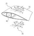
도 1은 종래 기술에 따른 풍력 발전 장치를 도시한 사시도이다. 도 1에 도시된 바와 같이 종래의 풍력 발전 장치(1)는 타워(10), 나셀(30), 허브(21) 및 복수개의 블레이드(20)를 포함한다. 나셀(30)은 타워(10)의 상부에 고정되어 있고, 허브(21)는 회전 가능하도록 나셀(30)에 결합되어 있는 수평축에 결합되어 있으며, 블레이드(20)는 바람에 의하여 회전할 수 있도록 허브(21)에 결합되어 있다. 도 1에 도시된 블레이드(20)는 그 수가 3개이지만 이에 한정되는 것은 아니다.1 is a perspective view showing a conventional wind power generator. 1, a conventional
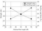
도 2 및 도 3은 종래 기술에 따른 풍력 발전 장치용 블레이드를 도시한 단면도이고, 도 4는 종래 기술에 따른 풍력 발전 장치용 블레이드의 인장강도 및 좌굴강도에 대한 실험 데이터이다.FIGS. 2 and 3 are cross-sectional views showing a blade for a wind power generator according to the prior art, and FIG. 4 is experimental data on tensile strength and buckling strength of a blade for a wind power generator according to the prior art.
도 2에 도시된 바와 같이, 블레이드(20)의 단면구조에 알 수 있듯이 블레이드(20)는 표면을 형성하며 서로 마주 보도록 배치된 2개의 스킨(PS,SS) 및 이 2개의 스킨 사이를 지지하는 스파캡(spar cap, 미도시)를 포함하여 구성될 수 있다. 여기서, 각각의 스킨(PS,SS)은 차례로 적층된 제1 섬유시트(S1), 코어(C) 및 제2 섬유시트(S2)를 포함할 수 있다.As can be seen from the cross-sectional structure of the
블레이드(20)의 스킨 중 제1 스킨(PS)은 바람의 힘을 받는 쪽 스킨이고, 제1 스킨(PS)과 마주보는 제2 스킨(SS)은 바람의 힘을 받지 않는 쪽의 스킨이다. 바람의 힘을 받는 제1 스킨(PS)은 Pressure side skin이며 인장력을 받게 된다. 바람의 힘을 받지 않는 제2 스킨(SS)은 Suction side skin이며 압축력을 받게 된다. 이와 같이, 블레이드(20)의 양쪽 스킨(PS,SS)에는 서로 다른 힘이 작용하게 된다.The first skin (PS) of the skin of the
블레이드(20)의 스킨(PS,SS)의 섬유시트는 섬유를 여러 가닥 배향 직조하여 형성되는데, 종래의 블레이드(20)는 직조된 섬유 가닥 사이의 배향각도가 제1 스킨(PS)이나 제2 스킨(SS)이나 동일하다. 도 3에 도시된 바와 같이, 바람의 힘을 받는 제1 스킨(PS)의 섬유시트(26)의 섬유배향각도는 0도/±45도이고, 바람의 힘을 받지 않는 제2 스킨(SS)의 섬유시트(21)의 섬유배향각도도 0도/±45도이다. 즉, 바람의 힘을 받아 인장력이 작용하는 제1 스킨(PS)을 형성하는 섬유는 0도/±45도 방향으로 배향되고, 바람의 힘을 받지 않아 압축력이 작용하는 제2 스킨(SS)을 형성하는 섬유도 0도/±45도 방향으로 배향된다.The fiber sheets of the skins PS and SS of the
이와 같이, 종래기술에 따른 블레이드(20)는 제1 스킨(PS)과 제2 스킨(SS)에 있어서 섬유의 배향각도가 동일하게 되어 있다.As described above, in the
바람의 힘을 받지 않지만 압축력이 작용하는 제2 스킨(SS)의 경우에는 섬유가 0도/±45도의 배향 각도를 가지기 때문에 좌굴(Bucking)에 가장 강한 특성을 가질 수 있다. 하지만, 바람의 힘을 받아서 인장력이 작용하는 제1 스킨(PS)의 경우에는 섬유가 0도/±45도의 배향 각도를 가지게 되어 인장 강도에 취약한 문제가 있다. 즉, 종래기술에 따른 풍력 발전 장치용 블레이드는 제1 스킨(PS)과 제2 스킨(SS)의 섬유가 동일한 배향각도(0도/±45도)를 가지기 때문에 제2 스킨(SS)은 좌굴에 강한 반면에 제1 스킨(PS)은 인장강도가 크지 않다는 문제가 있다.In the case of the second skin (SS), which is not subjected to the force of wind but has a compressive force, the fiber has the strongest characteristic to bucking since it has an orientation angle of 0 degrees / +/- 45 degrees. However, in the case of the first skin (PS) subjected to the tensile force by the force of the wind, the fiber has an orientation angle of 0 degrees / +/- 45 degrees, which is problematic in tensile strength. That is, since the fibers of the first skin PS and the second skin SS have the same orientation angle (0 deg. / +/- 45 deg.) In the blade for a wind power generator according to the related art, Whereas the first skin (PS) has a problem that the tensile strength is not large.
도 4를 참조하면, 인장 강도(Strengths)는 섬유 각도(Fiber angle)이 45도인 경우에 작은 반면에, 좌굴 강도(Buckling loads)는 45도에서 큰 것을 알 수 있다.Referring to FIG. 4, it can be seen that the tensile strengths are small at a fiber angle of 45 degrees, while the buckling loads are large at 45 degrees.
본 발명은 제1 스킨과 제2 스킨에 대해서 섬유의 배향각도를 서로 다르게 함으로써 좌굴에 대한 강도와 인장에 대한 강도를 모두 높일 수 있는 풍력 발전 장치용 블레이드를 제공한다.The present invention provides a blade for a wind power generator capable of enhancing the strength against buckling and the strength against tensile by making the orientation angles of the fibers different for the first skin and the second skin.
본 발명은 블레이드의 스킨 중 바람의 힘이 직접 가해지는 스킨과 그 스킨의 반대편에 있는 스킨에 대해서 섬유의 배향각도를 다르게 형성하여 스킨의 인장 강도를 개선할 수 있는 풍력 발전 장치용 블레이드를 제공한다.The present invention provides a blade for a wind power generator capable of improving the tensile strength of a skin by forming an orientation angle of fibers differently from a skin directly applied with the force of wind and a skin opposite to the skin of the blade .
상기한 과제를 달성하기 위한 본 발명의 일 실시예에 따른 풍력 발전 장치용 블레이드는, 일면에 배치되는 제1 스킨; 및 상기 제1 스킨과 마주하도록 타면에 배치되는 제2 스킨;을 포함하며, 상기 제1 스킨을 형성하는 섬유의 배향각도는 상기 제2 스킨을 형성하는 섬유의 배향각도와 다르게 형성될 수 있다.According to an aspect of the present invention, there is provided a blade for a wind power generator including: a first skin disposed on one surface; And a second skin disposed on the other surface to face the first skin, wherein an orientation angle of the fibers forming the first skin is different from an orientation angle of the fibers forming the second skin.
상기와 같이 구성함으로써, 바람을 받는 스킨의 인장강도를 높일 수 있고 바람을 받는 쪽의 반대편 스킨의 좌굴강도를 높일 수 있다.With this configuration, it is possible to increase the tensile strength of the wind-receiving skin and increase the buckling strength of the skin on the opposite side of the wind-receiving side.
상기 제1 스킨을 형성하는 섬유의 배향각도는 상기 제2 스킨을 형성하는 섬유의 배향각도 보다 작게 형성될 수 있다.The orientation angle of the fibers forming the first skin may be smaller than the orientation angle of the fibers forming the second skin.
상기 제1 스킨에는 인장력이 작용하고, 상기 제2 스킨에는 압축력이 작용할 수 있다.A tensile force acts on the first skin, and a compressive force acts on the second skin.
상기 제1 스킨의 섬유는 최대 인장하중에 견디는 배향각도를 가지고, 상기 제2 스킨의 섬유는 최대 좌굴하중에 견디는 배향각도를 가질 수 있다.The fibers of the first skin may have an orientation angle to withstand the maximum tensile load, and the fibers of the second skin may have an orientation angle to withstand the maximum buckling load.
한편, 본 발명의 일 실시예에 따른 풍력 발전 장치용 블레이드는 바람을 받는 쪽에 형성되며, 제1 인장섬유 및 제2 인장섬유를 포함하는 인장섬유시트를 구비하는 제1 스킨; 및 상기 제1 스킨과 마주하도록 타면에 형성되며, 제1 압축섬유 및 제2 압축섬유를 포함하는 압축섬유시트를 구비하는 제2 스킨;을 포함하며, 상기 제1 압축섬유와 상기 제2 압축섬유 사이의 각도는 상기 제1 인장섬유와 상기 제2 인장섬유 사이의 각도와 다르게 형성될 수 있다.According to another aspect of the present invention, there is provided a blade for a wind power generator, comprising: a first skin formed on a windward side and having a tensile fiber sheet including first tensile fibers and second tensile fibers; And a second skin formed on the other surface facing the first skin, the second skin comprising a first compressed fiber and a second compressed fiber sheet, wherein the first compressed fiber and the second compressed fiber May be formed differently from the angle between the first tensile fiber and the second tensile fiber.
상기 제1 압축섬유와 상기 제2 압축섬유 사이의 각도는 상기 제1 인장섬유와 상기 제2 인장섬유 사이의 각도 보다 크게 형성될 수 있다.The angle between the first compressed fiber and the second compressed fiber may be larger than the angle between the first tensile fiber and the second tensile fiber.
상기 압축섬유시트는 상기 제1 압축섬유와 상기 제2 압축섬유 사이에 형성되는 제3 압축섬유를 더 포함하고, 상기 제3 압축섬유에 대한 상기 제1 압축섬유의 배향각도는 상기 제3 압축섬유에 대한 상기 제2 압축섬유의 배향각도와 같게 형성될 수 있다.Wherein the first compressed fiber sheet further comprises a third compressed fiber formed between the first compressed fiber and the second compressed fiber, and an orientation angle of the first compressed fiber with respect to the third compressed fiber is smaller than an orientation angle of the third compressed fiber with respect to the third compressed fiber. The angle of orientation of the second compressed fiber with respect to the first compressed fiber may be the same.
상기 인장섬유시트는 상기 제1 인장섬유와 상기 제2 인장섬유 사이에 형성되는 제3 인장섬유를 더 포함하고, 상기 제3 인장섬유에 대한 상기 제1 인장섬유의 배향각도는 상기 제3 인장섬유에 대한 상기 제2 인장섬유의 배향각도와 같거나 다르게 형성될 수 있다.Wherein the tensile fiber sheet further comprises a third tensile fiber formed between the first tensile fiber and the second tensile fiber, the orientation angle of the first tensile fiber with respect to the third tensile fiber being greater than the angle of orientation of the third tensile fiber with respect to the third tensile fiber The angle of orientation of the second tensile fibers with respect to the first tensile fibers may be equal to or different from that of the second tensile fibers.
상기 제1 스킨은 상기 인장섬유시트를 복수개 적층하여 형성되고, 상기 제2 스킨은 상기 압축섬유시트를 복수개 적층하여 형성될 수 있다.The first skin may be formed by laminating a plurality of the tensile fiber sheets, and the second skin may be formed by laminating a plurality of the compressed fiber sheets.
상기 제1 인장섬유 및 상기 제2 인장섬유 중 어느 하나는 0도의 배향각도를 가지고 다른 하나는 0도인 인장섬유에 대해 25도 내지 35도의 배향각도를 가지고, 상기 제1 압축섬유 및 상기 제2 압축섬유 중 어느 하나는 0도의 배향각도를 가지고 다른 하나는 0도인 압축섬유에 대해 45도의 배향각도를 가질 수 있다.Wherein one of the first tensile fiber and the second tensile fiber has an orientation angle of 25 degrees to 35 degrees with respect to the tensile fiber having an orientation angle of 0 degrees and the other one being 0 degrees, Either one of the fibers may have an orientation angle of 0 degrees and the other one may have an orientation angle of 45 degrees with respect to the 0 degree compressed fibers.
또한, 본 발명의 일 실시예에 따른 풍력 발전 장치용 블레이드는 0도의 배향각도를 가지는 위사인장섬유 및 상기 위사인장섬유에 대해 인장배향각도를 가지는 경사인장섬유를 포함하는 인장섬유시트를 구비하는 제1 스킨; 및 0도의 배향각도를 가지는 위사압축섬유 및 상기 위사압축섬유에 대해 압축배향각도를 가지는 경사압축섬유를 포함하는 압축섬유시트를 구비하는 제2 스킨;을 포함하며, 상기 제1 스킨은 상기 위사인장섬유를 기준으로 상기 인장배향각도가 대칭 또는 비대칭이 되도록 상기 인장섬유시트를 적어도 하나 적층하여 형성되고, 상기 제2 스킨은 상기 위사압축섬유를 기준으로 상기 압축배향각도가 대칭이 되도록 상기 압축섬유시트를 적어도 하나 적층하여 형성될 수 있다.Further, the blade for a wind power generator according to an embodiment of the present invention includes a tensile fiber sheet having an oriented angle of 0 degrees and a tensile fiber sheet having a tensile orientation angle with respect to the weft- 1 skin; And a second skin comprising a woven and compressed fiber having an orientation angle of 0 degrees and a compressed fiber sheet including warp-compressed fibers having a compression orientation angle with respect to the weft-oriented compressed fiber, And the second skin is formed by laminating at least one of the tensile fiber sheets so that the tensile orientation angle is symmetrical or asymmetrical with respect to the fiber, As shown in FIG.
상기 인장배향각도와 상기 압축배향각도는 서로 다르게 형성될 수 있다.The tensile orientation angle and the compression orientation angle may be different from each other.
상기 인장배향각도는 상기 압축배향각도 보다 작게 형성될 수 있다.The tensile orientation angle may be smaller than the compression orientation angle.
상기 인장배향각도는 25도 내지 35도로 형성되고, 상기 압축배향각도는 45도로 형성될 수 있다.The tensile orientation angle may be 25 to 35 degrees, and the compression orientation angle may be 45 degrees.
이상 설명한 바와 같이, 본 발명에 따른 자속 풍력 발전 장치용 블레이드는 바람의 힘이 직접 가해지는 스킨과 그 스킨의 반대편에 있는 스킨에 대해서 섬유의 배향각도를 다르게 형성하여 스킨의 인장 강도를 개선함과 동시에 스킨의 좌굴 강도도 유지할 수 있다.INDUSTRIAL APPLICABILITY As described above, the blade for a magnetic flux wind power generator according to the present invention improves the tensile strength of a skin by forming a fiber orientation angle differently from a skin directly applied with wind force and a skin opposite to the skin, At the same time, the buckling strength of the skin can be maintained.
본 발명에 따른 풍력 발전 장치용 블레이드는 블레이드의 크기가 큰 경우에도 인장강도와 좌굴강도를 높게 유지할 수 있기 때문에 블레이드의 대형화로 인한 한계를 극복할 수 있다.The blade for a wind power generator according to the present invention can keep the tensile strength and the buckling strength high even when the size of the blade is large, thereby overcoming the limit due to the enlargement of the blade.
도 1은 종래 기술에 따른 풍력 발전 장치를 도시한 사시도이다.
도 2 및 도 3은 종래 기술에 따른 풍력 발전 장치용 블레이드를 도시한 단면도이다.
도 4는 종래 기술에 따른 풍력 발전 장치용 블레이드의 인장강도 및 좌굴강도에 대한 실험 데이터이다.
도 5는 본 발명의 일 실시예에 따른 풍력 발전 장치용 블레이드의 제1 스킨을 도시한 도면이다.
도 6은 본 발명의 일 실시예에 따른 풍력 발전 장치용 블레이드의 제2 스킨을 도시한 도면이다.
도 7은 본 발명의 일 실시예에 따른 풍력 발전 장치용 블레이드의 제1 및 제2 스킨의 인장강도와 좌굴강도에 대한 실험 데이터이다.
도 8은 본 발명의 일 실시예에 따른 풍력 발전 장치용 블레이드의 스킨에 작용하는 힘들을 도시한 도면이다.
도 9는 본 발명의 일 실시예에 따른 블레이드의 섬유 각도 및 섬유 재질에 따른 피로강도를 보여주는 실험데이터이다.1 is a perspective view showing a conventional wind power generator.
2 and 3 are sectional views showing a blade for a wind power generator according to the prior art.
4 is experimental data on tensile strength and buckling strength of a blade for a wind power generator according to the prior art.
5 is a view showing a first skin of a blade for a wind power generator according to an embodiment of the present invention.
6 is a view showing a second skin of a blade for a wind power generator according to an embodiment of the present invention.
7 is experimental data on tensile strength and buckling strength of first and second skins of a blade for a wind power generator according to an embodiment of the present invention.
8 is a view showing forces acting on a skin of a blade for a wind power generator according to an embodiment of the present invention.
9 is experimental data showing the fiber angle and the fatigue strength according to the fiber material of the blade according to an embodiment of the present invention.
이하에서, 첨부된 도면을 참조하여 본 발명에 따른 실시예들을 상세하게 설명한다. 그러나, 본 발명이 실시예들에 의해 제한되거나 한정되는 것은 아니다. 각 도면에 제시된 동일한 참조 부호는 동일한 부재를 나타낸다.Hereinafter, embodiments according to the present invention will be described in detail with reference to the accompanying drawings. However, the present invention is not limited to or limited by the embodiments. Like reference symbols in the drawings denote like elements.
도 5는 본 발명의 일 실시예에 따른 풍력 발전 장치용 블레이드의 제1 스킨을 도시한 도면, 도 6은 본 발명의 일 실시예에 따른 풍력 발전 장치용 블레이드의 제2 스킨을 도시한 도면, 도 7은 본 발명의 일 실시예에 따른 풍력 발전 장치용 블레이드의 제1 및 제2 스킨의 인장강도와 좌굴강도에 대한 실험 데이터, 도 8은 본 발명의 일 실시예에 따른 풍력 발전 장치용 블레이드의 스킨에 작용하는 힘들을 도시한 도면, 도 9는 본 발명의 일 실시예에 따른 블레이드의 섬유 각도 및 섬유 재질에 따른 피로강도를 보여주는 실험데이터이다.FIG. 5 is a view showing a first skin of a blade for a wind power generator according to an embodiment of the present invention, FIG. 6 is a view showing a second skin of a blade for a wind power generator according to an embodiment of the present invention, FIG. 7 is a graph showing experimental data on tensile strength and buckling strength of first and second skins of a blade for a wind power generator according to an embodiment of the present invention, and FIG. FIG. 9 is experimental data showing the fiber angle of the blade and the fatigue strength according to the fiber material according to an embodiment of the present invention. FIG.
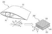
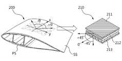
도 5 및 도 6에 도시된 바와 같이, 본 발명의 일 실시예에 따른 풍력 발전 장치용 블레이드(200)는, 일면에 배치되는 제1 스킨(PS) 및 제1 스킨(PS)과 마주하도록 타면에 배치되는 제2 스킨(SS)을 포함하며, 제1 스킨(PS)을 형성하는 섬유의 배향각도는 제2 스킨(SS)을 형성하는 섬유의 배향각도와 다르게 형성될 수 있다.5 and 6, a
상기와 같이 구성함으로써, 바람을 받는 제1 스킨(PS)의 인장강도를 높일 수 있고 바람을 받는 쪽의 반대편에 있는 제2 스킨(SS)의 좌굴강도도 높일 수 있다.With this configuration, the tensile strength of the wind-receiving first skin PS can be increased and the buckling strength of the second skin SS on the opposite side of the wind-receiving side can be increased.
본 발명의 일 실시예에 따른 풍력 발전 장치용 블레이드(200)는 스킨(PS,SS)의 구조가 종래기술에 따른 블레이드의 구조와 상이하다. 즉, 상기에서 언급한 바와 같이, 바람을 직접 맞이하기 때문에 바람의 힘이 작용하는 제1 스킨(PS)을 형성하는 섬유(261,262,263)의 배향각도(α,β)는 바람의 힘이 직접 작용하지 않는 제2 스킨(SS)을 형성하는 섬유(211,212,213)의 배향각도(0도/±45도)를 다르다.In the
제1 스킨(PS)에는 인장력이 작용하고, 제2 스킨(SS)에는 압축력이 작용할 수 있다. 제1 스킨(PS)에는 바람의 힘이 직접 작용하기 때문에 인장력이 걸리게 되고, 제1 스킨(PS)을 형성하는 인장섬유시트(260)는 2가닥 또는 3가닥의 섬유를 직조하여 형성될 수 있다. 도 5에 도시된 인장섬유시트(260)의 경우에는 3가닥의 섬유를 직조한 경우가 예시적으로 되어 있다. 즉, 1장의 인장섬유시트(260)는 3가닥의 섬유를 직조하여 형성될 수 있다.A tensile force acts on the first skin PS and a compressive force acts on the second skin SS. The tensile force is applied to the first skin PS because the force of the wind acts directly on the first skin PS and the
도 5에서 인장섬유시트(260)는 배향각도가 0도인 위사인장섬유(262)를 기준으로 그 상하에 각각 섬유(261,263)가 직조되는데, 위사인장섬유(262)에 대해서 그 상하에 있는 경사인장섬유(261,263)는 각각 소정의 각도로 이루며 경사진 상태로 직조될 수 있다. 여기서, 위사인장섬유(262)에 대한 경사인장섬유(261,263)의 배향각도는 도 6에 도시된 압축섬유시트(210)의 위사압축섬유(212)에 대한 경사압축섬유(211,213)의 배향 각도와 동일하지 않다.5, the
제1 스킨(PS)을 형성하는 섬유(261,262,263)의 배향각도는 제2 스킨(SS)을 형성하는 섬유(211,212,213)의 배향각도 보다 작게 형성될 수 있다.The orientation angle of the
이 때, 제1 스킨(PS)의 인장섬유시트(260)를 형성하는 섬유(261,262,263) 사이의 배향각도는 25도 내지 35도가 되는 반면에, 제2 스킨(SS)의 압축섬유시트(210)를 형성하는 섬유(211,212,213) 사이의 배향각도는 0도, +45도 또는 -45도가 될 수 있다. 즉, 압축력을 받는 제2 스킨(SS)은 종래의 블레이드와 동일한 섬유 배향각도를 가진다. 따라서, 제2 스킨(SS) 또는 제2 스킨(SS)의 섬유는 최대 좌굴하중에 견디는 배향각도를 가질 수 있다.At this time, the orientation angle between the
본 발명에 따른 블레이드(200)의 제1 스킨(PS)의 인장섬유시트(260)를 형성하는 섬유들은 최대 인장하중에 견디는 배향각도를 가질 수 있다. 이를 위해, 제1 스킨(PS)의 인장섬유시트(260)를 형성하는 섬유(261,262,263) 사이의 배향각도는 45도 보다 작은 25도 내지 35도가 바람직하다.Fibers forming the
인장섬유시트(260)를 형성하는 섬유(261,262,263) 사이의 배향각도를 25도 보다 더 작게 할 수 있다면 제1 스킨(PS)의 인장강도를 더 크게 할 수 있을 것이다. 하지만, 인장섬유시트(260)를 형성하는 섬유(261,262,263) 사이의 배향각도를 25도 보다 더 작게 하는 경우에는 인장섬유시트(260)의 제작이 쉽지 않다는 단점이 있다. 특히나, 블레이드의 크기가 대형인 경우에 섬유(261,262,263) 사이의 배향각도가 25도 보다 더 작은 인장섬유시트(260)를 만들거나 직조하기 위해서는 매우 큰 장비가 필요하다는 문제가 있다.If the orientation angle between the
또한, 제1 스킨(PS)의 인장섬유시트(260)의 인장강도를 크게 하기 위해 섬유들(261,262,263) 사이의 배향각도를 0도 내지 25도 정도로 한다면, 인장섬유시트(260)에 작용하는 측면하중 내지는 비틀림하중에 의해서 섬유가 끊어지거나 뜯어질 가능성이 크다. 도 8에는 제2 스킨(SS)의 압축섬유시트(210)에 작용하는 힘이 도시되어 있는데, 제1 스킨(PS)에도 유사한 방향으로 힘이 작용할 수 있다. 도 8을 참조하면, 압축섬유시트(210)에는 측면하중(σ1)과 비틀림하중(σ6)가 모두 작용한다. 이러한 힘들에 의해서 배향각도가 25도 보다 작은 섬유의 경우에는 끊어지거나 뜯어질 가능성이 매우 높다. 따라서, 인장강도를 크게 하기 위해서 인장섬유시트(260)의 섬유배향각도를 0도에 근접하는 정도로 작게 할 수는 없다. 이러한 문제를 방지하기 위해서, 본 발명의 일 실시예에 따른 풍력 발전 장치용 블레이드(200)는 바람의 힘이 직접 작용해서 인장력이 걸리는 제1 스킨(PS)의 인장섬유시트(260)의 섬유배향 각도를 25도 내지 35도로 함으로써 제1 스킨(PS)의 인장 강도를 높일 수 있다.Further, if the orientation angle between the
도 5에 도시된 인장섬유시트(260)는 3가닥의 섬유를 직조하여 형성되는데, 가운데 있는 위사인장섬유(262)는 배향각도가 0도이다. 위사인장섬유(262)를 기준으로 상하에 직조되는 경사인장섬유(261,263) 중 어느 하나는 +25도 내지 +35도의 배향각도를 가지고 다른 하나는 -25도 내지 -35도의 배향각도를 가질 수 있다. 여기서, 위사인장섬유(262)를 기준으로 상하에 각각 배치 또는 직조되는 경사인장섬유(261,263)의 배향각도는 서로 같을 수도 있고, 다를 수도 있다.The tensioned
예를 들면, 위사인장섬유(262)를 기준으로 위쪽에 직조되는 경사인장섬유(261)의 배향각도가 +30도이고 아래쪽에 직조되는 경사인장섬유(263)의 배향각도가 -30도가 될 수도 있다. 이와 같이, 상하의 경사인장섬유(261,263)의 배향각도가 동일한 경우에는 경사인장섬유(261,263)가 대칭인 상태로 직조된다고 할 수 있다. 반면에, 위사인장섬유(262)를 기준으로 위쪽에 직조되는 경사인장섬유(261)의 배향각도가 +30도이고 아래쪽에 직조되는 경사인장섬유(263)의 배향각도가 -25도가 될 수도 있다. 이와 같이, 상하의 경사인장섬유(261,263)의 배향각도가 서로 다른 경우에는 경사인장섬유(261,263)가 비대칭인 상태로 직조된다고 할 수 있다.For example, if the orientation angle of the
도 5 및 도 6에 도시된 인장섬유시트(260) 및 압축섬유시트(210)는 각각 2가닥의 섬유로 형성되어 있는데, 각각 2가닥의 섬유로 형성될 수도 있다.The
즉, 본 발명의 일 실시예에 따른 풍력 발전 장치용 블레이드(200)의 제1 스킨(PS)의 인장섬유시트(260)는 제1 인장섬유(261) 및 제2 인장섬유(263)를 직조하여 형성될 수도 있다. 이 때, 제1 인장섬유(261)와 제2 인장섬유(263) 사이의 섬유배향각도는 50도 내지 70도가 될 수 있다.That is, the
마찬가지로, 제2 스킨(SS)의 압축섬유시트(210)는 제1 압축섬유(211) 및 제2 압축섬유(213)를 직조하여 형성될 수도 있다. 이 때, 제1 압축섬유(211)와 제2 압축섬유(213) 사이의 섬유배향각도는 90도가 될 수 있다.Similarly, the
이와 같이, 본 발명의 일 실시예에 따른 풍력 발전 장치용 블레이드(200)는 2가닥의 인장섬유(261,263)로 직조된 인장섬유시트(260)를 구비하는 제1 스킨(PS) 및 2가닥의 압축섬유(211,213)로 직조된 압축섬유시트(210)를 구비하는 제2 스킨(SS)을 포함하며, 압축섬유시트(210)의 섬유배향각도는 인장섬유시트(260)의 섬유배향각도와 다르게 형성될 수 있다.As described above, the
제1 압축섬유(211)와 제2 압축섬유(213) 사이의 각도(90도)는 제1 인장섬유(261)와 제2 인장섬유(263) 사이의 각도(50도~70도) 보다 크게 형성될 수 있다.The angle (90 degrees) between the first
한편, 상기에서 설명한 바와 같이, 인장섬유시트(260)와 압축섬유시트(210)는 3가닥의 섬유를 직조하여 형성될 수도 있다. 압축섬유시트(210)는 제1 압축섬유(211)와 제2 압축섬유(213) 사이에 형성되는 제3 압축섬유(212)를 더 포함하고, 제3 압축섬유(212)에 대한 제1 압축섬유(211)의 배향각도(45도)는 제3 압축섬유(212)에 대한 제2 압축섬유(213)의 배향각도(45도)와 같게 형성될 수 있다.Meanwhile, as described above, the
인장섬유시트(260)는 제1 인장섬유(261)와 제2 인장섬유(263) 사이에 형성되는 제3 인장섬유(262)를 더 포함하고, 제3 인장섬유(262)에 대한 제1 인장섬유(261)의 배향각도(25도~35도)는 제3 인장섬유(262)에 대한 제2 인장섬유(263)의 배향각도(25도~35도)와 같거나 다르게 형성될 수 있다. 즉, 대칭 또는 비대칭 형태로 직조될 수 있다.The
제1 스킨(PS)은 인장섬유시트(260)를 복수개 적층하여 형성되고, 제2 스킨(SS)은 압축섬유시트(210)를 복수개 적층하여 형성될 수 있다.The first skin PS may be formed by laminating a plurality of
한편, 2가닥의 섬유만을 이용하여 인장섬유시트(260) 및 압축섬유시트(210)를 형성하는 경우, 어느 한 가닥의 섬유를 위사(緯絲)로 하고 나머지 한 가닥의 섬유를 경사(經絲)로 할 수 있다. 즉, 제1 인장섬유(261) 및 제2 인장섬유(263) 중 어느 하나는 0도의 배향각도를 가지는 위사인장섬유이고 다른 하나는 0도인 위사인장섬유에 대해 25도 내지 35도의 배향각도를 가지는 경사인장섬유이며, 제1 압축섬유(211) 및 제2 압축섬유(213) 중 어느 하나는 0도의 배향각도를 가지는 위사압축섬유이고 다른 하나는 0도인 위사압축섬유에 대해 45도의 배향각도를 가지는 경사압축섬유가 될 수 있다.On the other hand, when the
이와 같이, 2가닥을 직조하여 만들어진 인장섬유시트(260) 및 압축섬유시트(210)를 여러 개 적층하여 스킨()을 형성하는 경우, 배향각도가 0도인 위사압축섬유(211)가 서로 일치하도록 압축섬유시트(210)를 적층하면 경사압축섬유(213)도 서로 일치하도록 적층될 수 있다. 왜냐하면, 압축섬유시트(210)의 섬유배향각도는 45도로 일정하기 때문이다.In this way, when a plurality of
반면에, 배향각도가 0도인 위사인장섬유(261)가 서로 일치하도록 인장섬유시트(260)를 적층하면 경사인장섬유(263)는 서로 일치하도록 적층될 수 있지만, 일치하지 않은 상태로 적층될 수도 있다. 인장섬유시트(260)를 적층하여 형성되는 제1 스킨(PS)은 섬유배향각도가 위사인장섬유(262)를 기준으로 상하의 섬유가 동일할 수도 있고 다를 수도 있기 때문이다.On the other hand, when the
다시 설명해 보면, 본 발명의 일 실시예에 따른 풍력 발전 장치용 블레이드(200)는 0도의 배향각도를 가지는 위사인장섬유(262) 및 위사인장섬유(262)에 대해 인장배향각도를 가지는 경사인장섬유(261,263)를 포함하는 인장섬유시트(260)를 구비하는 제1 스킨(PS) 및 0도의 배향각도를 가지는 위사압축섬유(212) 및 위사압축섬유(212)에 대해 압축배향각도를 가지는 경사압축섬유(211,213)를 포함하는 압축섬유시트(210)를 구비하는 제2 스킨(SS)을 포함하며, 제1 스킨(PS)은 위사인장섬유(262)를 기준으로 인장배향각도가 대칭 또는 비대칭이 되도록 인장섬유시트(260)를 적어도 하나 적층하여 형성되고, 제2 스킨(SS)은 위사압축섬유(212)를 기준으로 압축배향각도가 대칭이 되도록 압축섬유시트(210)를 적어도 하나 적층하여 형성될 수 있다.In other words, the
여기서, 인장섬유시트(260)의 인장배향각도와 압축섬유시트(210)의 압축배향각도는 서로 다르게 형성될 수 있고, 인장배향각도는 압축배향각도 보다 작게 형성될 수 있다. 인장섬유시트(260)의 인장배향각도는 25도 내지 35도로 형성되고, 압축섬유시트(210)는 압축배향각도는 45도로 형성될 수 있다.Here, the tensile orientation angle of the
제2 스킨(SS)은 적어도 하나의 압축섬유시트(210)를 적층함에 있어서, 압축배향각도가 항상 45도이며, 모든 압축섬유시트(210)의 압축배향각도가 일치하도록 적층될 수 있다. 이와 같이, 제2 스킨(SS)은 섬유배향각도가 45도이기 때문에 최적의 좌굴강도를 유지할 수 있다. 도 7에 도시된 바와 같이, 좌굴강도(Buckling loads)는 45도에서 최대임을 알 수 있다.The second skin (SS) can be laminated so that the compression orientation angle is always 45 degrees and the compression orientation angles of all the
한편, 제1 스킨(PS)은 적어도 하나의 인장섬유시트(260)를 적층함에 있어서, 인장배향각도가 25도 내지 35도이기 때문에 모든 인장섬유시트(260)의 인장배향각도가 동일할 수도 있고(대칭) 동일하지 않을 수도 있다(비대칭). 도 7을 참조하면 인장강도(Strengths)는 인장배향각도가 45도인 경우 보다 25도 내지 35도인 경우가 큼을 알 수 있다.On the other hand, in the case of laminating at least one
본 발명의 일 실시예에 따른 풍력 발전 장치용 블레이드(200)의 제1 스킨(PS) 및 제2 스킨(SS)을 형성하는 섬유시트(210,260)는 유리섬유(glass fiber) 또는 탄소섬유(carbon fiber)로 만들어질 수도 있다. 뿐만 아니라 유리섬유와 탄소섬유를 혼합한 복합재 또는 하이브리드 섬유로 만들어질 수도 있다.The
도 9의 (a) 와 (b) 탄소섬유와 유리섬유 각각에 두 종류의 섬유배향각도(0도/+45도/-45도)와 (0도/+25도/-25도)에 대한 인장 하중의 피로 수명 (S-N curve)을 보여주는 데이터이다. 탄소섬유와 유리섬유의 경우 모두 배향각도가 25도인 경우가 45도인 경우에 비해서 수명이 늘어남을 알 수 있다. 섬유배향각도가 25도인 탄소섬유와 유리섬유를 인장을 받는 제 1 스킨 (PS)에 사용하면 우수하다는 것을 보여준다.(0 degree / + 45 degrees / -45 degrees) and (0 degrees / + 25 degrees / -25 degrees) for two kinds of fiber orientation angles This is data showing the fatigue life (SN curve) of the tensile load. In the case of carbon fiber and glass fiber, the lifetime is increased as compared with the case where the orientation angle is 25 degrees at 45 degrees. The use of carbon fibers and glass fibers with a fiber orientation angle of 25 degrees on the first skin (PS) to be stretched is superior.
지금까지 설명한 바와 같이, 본 발명의 일 실시예에 따른 풍력 발전 장치용 블레이드는 바람이 직접 작용하고 인장력이 걸리는 스킨의 섬유배향각도와 바람이 직접 작용하지 않고 압축력이 걸리는 스킨의 섬유배향각도를 다르게 함으로써, 블레이드의 인장강도와 좌굴강도를 모두 확보할 수 있기 때문에, 블레이드의 수명을 늘일 수 있고 블레이드가 대형화하는 경우에도 제한없이 블레이드를 제조할 수 있다는 장점이 있다.As described so far, the blade for a wind power generator according to an embodiment of the present invention has a fiber orientation angle of a skin that directly acts on the wind and a tensile force is applied, and a fiber orientation angle of the skin, Thus, both the tensile strength and the buckling strength of the blade can be ensured. This makes it possible to increase the lifetime of the blade and to manufacture the blade regardless of the size of the blade.
이상과 같이 본 발명의 일 실시예에서는 구체적인 구성 요소 등과 같은 특정 사항들과 한정된 실시예 및 도면에 의해 설명되었으나 이는 본 발명의 보다 전반적인 이해를 돕기 위해서 제공된 것일 뿐, 본 발명은 상기의 실시예에 한정되는 것은 아니며, 본 발명이 속하는 분야에서 통상적인 지식을 가진 자라면 이러한 기재로부터 다양한 수정 및 변형이 가능하다. 따라서, 본 발명의 사상은 설명된 실시예에 국한되어 정해져서는 아니 되며, 후술하는 특허청구범위뿐 아니라 이 특허청구범위와 균등하거나 등가적 변형이 있는 모든 것들은 본 발명 사상의 범주에 속한다고 할 것이다.While the present invention has been described in connection with what is presently considered to be practical exemplary embodiments, it is to be understood that the invention is not limited to the disclosed embodiments, but, on the contrary, It will be understood by those skilled in the art that various changes in form and details may be made therein without departing from the spirit and scope of the invention as defined by the appended claims. Accordingly, the spirit of the present invention should not be construed as being limited to the embodiments described, and all of the equivalents or equivalents of the claims, as well as the following claims, belong to the scope of the present invention .
200: 풍력 발전 장치용 블레이드
210: 압축섬유시트
211,212,213: 압축섬유
260: 인장섬유시트
261,262,263: 인장섬유
PS: 제1 스킨
SS: 제2 스킨200: Blades for wind power devices
210: Compressed fiber sheet
211, 212, 213: Compressed fiber
260: tensile fiber sheet
261,262,263: Tensile fibers
PS: First skin
SS: 2nd skin
Claims (14)
Translated fromKorean상기 제1 스킨과 마주하도록 타면에 배치되는 제2 스킨;을 포함하며,
상기 제1 스킨을 형성하는 섬유의 배향각도는 상기 제2 스킨을 형성하는 섬유의 배향각도와 다른 것을 특징으로 하는 풍력 발전 장치용 블레이드.
A first skin disposed on one surface; And
And a second skin disposed on the other surface to face the first skin,
Wherein the orientation angle of the fibers forming the first skin is different from the orientation angle of the fibers forming the second skin.
상기 제1 스킨을 형성하는 섬유의 배향각도는 상기 제2 스킨을 형성하는 섬유의 배향각도 보다 작은 것을 특징으로 하는 풍력 발전 장치용 블레이드.
The method according to claim 1,
Wherein the orientation angle of the fibers forming the first skin is smaller than the orientation angle of the fibers forming the second skin.
상기 제1 스킨에는 인장력이 작용하고, 상기 제2 스킨에는 압축력이 작용하는 것을 특징으로 하는 풍력 발전 장치용 블레이드.
3. The method of claim 2,
Wherein a tensile force acts on the first skin and a compressive force acts on the second skin.
상기 제1 스킨의 섬유는 최대 인장하중에 견디는 배향각도를 가지고, 상기 제2 스킨의 섬유는 최대 좌굴하중에 견디는 배향각도를 가지는 것을 특징으로 하는 풍력 발전 장치용 블레이드.
3. The method of claim 2,
Wherein the fibers of the first skin have an orientation angle to withstand the maximum tensile load and the fibers of the second skin have an orientation angle that resists the maximum buckling load.
상기 제1 스킨과 마주하도록 타면에 형성되며, 제1 압축섬유 및 제2 압축섬유를 포함하는 압축섬유시트를 구비하는 제2 스킨;을 포함하며,
상기 제1 압축섬유와 상기 제2 압축섬유 사이의 각도는 상기 제1 인장섬유와 상기 제2 인장섬유 사이의 각도와 다르게 형성되는, 풍력 발전 장치용 블레이드.
A first skin formed on the wind receiving side and comprising a tensile fiber sheet comprising a first tensile fiber and a second tensile fiber; And
And a second skin formed on the other surface facing the first skin and having a compressed fiber sheet including first compressed fiber and second compressed fiber,
Wherein an angle between the first compressed fiber and the second compressed fiber is formed differently from an angle between the first tensile fiber and the second tensile fiber.
상기 제1 압축섬유와 상기 제2 압축섬유 사이의 각도는 상기 제1 인장섬유와 상기 제2 인장섬유 사이의 각도 보다 크게 형성되는, 풍력 발전 장치용 블레이드.
6. The method of claim 5,
Wherein an angle between the first compressed fiber and the second compressed fiber is formed larger than an angle between the first tensile fiber and the second tensile fiber.
상기 압축섬유시트는 상기 제1 압축섬유와 상기 제2 압축섬유 사이에 형성되는 제3 압축섬유를 더 포함하고,
상기 제3 압축섬유에 대한 상기 제1 압축섬유의 배향각도는 상기 제3 압축섬유에 대한 상기 제2 압축섬유의 배향각도와 같은 것을 특징으로 하는 풍력 발전 장치용 블레이드.
The method according to claim 6,
The compressed fiber sheet further comprises a third compressed fiber formed between the first compressed fiber and the second compressed fiber,
Wherein the orientation angle of the first compressed fiber with respect to the third compressed fiber is the same as the orientation angle of the second compressed fiber with respect to the third compressed fiber.
상기 인장섬유시트는 상기 제1 인장섬유와 상기 제2 인장섬유 사이에 형성되는 제3 인장섬유를 더 포함하고,
상기 제3 인장섬유에 대한 상기 제1 인장섬유의 배향각도는 상기 제3 인장섬유에 대한 상기 제2 인장섬유의 배향각도와 같거나 다른 것을 특징으로 하는 풍력 발전 장치용 블레이드.
8. The method of claim 7,
Wherein the tensile fiber sheet further comprises a third tensile fiber formed between the first tensile fiber and the second tensile fiber,
Wherein an orientation angle of the first tensile fiber with respect to the third tensile fiber is equal to or different from an orientation angle of the second tensile fiber with respect to the third tensile fiber.
상기 제1 스킨은 상기 인장섬유시트를 복수개 적층하여 형성되고, 상기 제2 스킨은 상기 압축섬유시트를 복수개 적층하여 형성되는, 풍력 발전 장치용 블레이드.
9. The method of claim 8,
Wherein the first skin is formed by laminating a plurality of the tensile fiber sheets, and the second skin is formed by laminating a plurality of the compressed fiber sheets.
상기 제1 인장섬유 및 상기 제2 인장섬유 중 어느 하나는 0도의 배향각도를 가지고 다른 하나는 0도인 인장섬유에 대해 25도 내지 35도의 배향각도를 가지고,
상기 제1 압축섬유 및 상기 제2 압축섬유 중 어느 하나는 0도의 배향각도를 가지고 다른 하나는 0도인 압축섬유에 대해 45도의 배향각도를 가지는, 풍력 발전 장치용 블레이드.
6. The method of claim 5,
Wherein one of the first tensile fiber and the second tensile fiber has an orientation angle of 25 degrees to 35 degrees with respect to the tensile fiber having an orientation angle of 0 degrees and the other of 0 degrees,
Wherein either one of the first compressed fiber and the second compressed fiber has an orientation angle of 0 degrees and the other has an orientation angle of 45 degrees with respect to the compressed fiber having 0 degrees.
0도의 배향각도를 가지는 위사압축섬유 및 상기 위사압축섬유에 대해 압축배향각도를 가지는 경사압축섬유를 포함하는 압축섬유시트를 구비하는 제2 스킨;을 포함하며,
상기 제1 스킨은 상기 위사인장섬유를 기준으로 상기 인장배향각도가 대칭 또는 비대칭이 되도록 상기 인장섬유시트를 적어도 하나 적층하여 형성되고,
상기 제2 스킨은 상기 위사압축섬유를 기준으로 상기 압축배향각도가 대칭이 되도록 상기 압축섬유시트를 적어도 하나 적층하여 형성되는, 풍력 발전 장치용 블레이드.
A first skin having a tensile fiber sheet including warp tension fibers having an orientation angle of 0 degrees and warp tension fibers having a tensile orientation angle with respect to the weft tension fibers; And
And a second skin comprising a woven and compressed fiber having an orientation angle of 0 degrees and a compressed fiber sheet including warp-compressed fibers having a compression orientation angle with respect to the weft-
Wherein the first skin is formed by stacking at least one of the tensile fiber sheets so that the tensile orientation angle is symmetrical or asymmetrical with respect to the weft tensile fiber,
Wherein the second skin is formed by stacking at least one of the compressed fiber sheets so that the compression orientation angle is symmetrical with respect to the weft-compressed fiber.
상기 인장배향각도와 상기 압축배향각도는 서로 다른 것을 특징으로 하는 풍력 발전 장치용 블레이드.
12. The method of claim 11,
Wherein the tensile orientation angle and the compression orientation angle are different from each other.
상기 인장배향각도는 상기 압축배향각도 보다 작은 것을 특징으로 하는 풍력 발전 장치용 블레이드.
12. The method of claim 11,
Wherein the tensile orientation angle is smaller than the compression orientation angle.
상기 인장배향각도는 25도 내지 35도이고, 상기 압축배향각도는 45도인 것을 특징으로 하는 풍력 발전 장치용 블레이드.12. The method of claim 11,
Wherein the tensile orientation angle is from 25 degrees to 35 degrees, and the compression orientation angle is 45 degrees.
Priority Applications (1)
| Application Number | Priority Date | Filing Date | Title |
|---|---|---|---|
| KR1020130026223AKR20140111829A (en) | 2013-03-12 | 2013-03-12 | Blade of wind energy facility |
Applications Claiming Priority (1)
| Application Number | Priority Date | Filing Date | Title |
|---|---|---|---|
| KR1020130026223AKR20140111829A (en) | 2013-03-12 | 2013-03-12 | Blade of wind energy facility |
Publications (1)
| Publication Number | Publication Date |
|---|---|
| KR20140111829Atrue KR20140111829A (en) | 2014-09-22 |
Family
ID=51757109
Family Applications (1)
| Application Number | Title | Priority Date | Filing Date |
|---|---|---|---|
| KR1020130026223AWithdrawnKR20140111829A (en) | 2013-03-12 | 2013-03-12 | Blade of wind energy facility |
Country Status (1)
| Country | Link |
|---|---|
| KR (1) | KR20140111829A (en) |
Cited By (1)
| Publication number | Priority date | Publication date | Assignee | Title |
|---|---|---|---|---|
| US20210317814A1 (en)* | 2018-09-03 | 2021-10-14 | Vestas Wind Systems A/S | Wind turbine blade design |
- 2013
- 2013-03-12KRKR1020130026223Apatent/KR20140111829A/ennot_activeWithdrawn
Cited By (2)
| Publication number | Priority date | Publication date | Assignee | Title |
|---|---|---|---|---|
| US20210317814A1 (en)* | 2018-09-03 | 2021-10-14 | Vestas Wind Systems A/S | Wind turbine blade design |
| US11913428B2 (en)* | 2018-09-03 | 2024-02-27 | Vestas Wind Systems A/S | Wind turbine blade design |
Similar Documents
| Publication | Publication Date | Title |
|---|---|---|
| EP2224127B1 (en) | Improved spar cap for wind turbine blades | |
| CN102465826B (en) | Main beam cap assembly for fan rotor blade | |
| CN1904353B (en) | Methods and apparatus for reducing load in a rotor blade | |
| EP2304228B1 (en) | A reinforced wind turbine blade | |
| US20100135816A1 (en) | Braided wind turbine blades and method of making same | |
| WO2013084634A1 (en) | Wind turbine and wind power generation device | |
| US20090196756A1 (en) | Wind turbine blades and method for forming same | |
| CN105298740B (en) | The rotor stiffening device of wind-driven generator | |
| KR20150128665A (en) | Triaxial fiber-reinforced composite laminate | |
| US11353003B2 (en) | Wind turbine blade and wind turbine | |
| US9267490B1 (en) | Aeroelastically coupled blades for vertical axis wind turbines | |
| EP4251410B1 (en) | Flow- enhancing fabric, spar cap and wind turbine blade and method for manufacturing a spar cap and wind turbine blade | |
| US10914284B2 (en) | Wind turbine blade | |
| US12202214B2 (en) | Interlayer, a spar cap and a wind turbine blade | |
| US8651822B2 (en) | Wind turbine rotor blade and wind-generating wind turbine | |
| EP2863052B1 (en) | Wind turbine rotor and wind turbine | |
| US20160377049A1 (en) | Structural support members with different areal weight fiber reinforcing layers for wind turbine rotor blades | |
| KR20140111829A (en) | Blade of wind energy facility | |
| JP2012112264A (en) | Blade for wind power generation and wind power generation device | |
| US12018643B2 (en) | Wind turbine rotor blade spar cap with equipotential bonding | |
| US10006436B2 (en) | Wind turbine rotor blades with load-transferring exterior panels | |
| Ragheb | Components of wind machines | |
| JPWO2013084634A1 (en) | Wind turbine blade and wind power generator | |
| EP2878806A1 (en) | Windmill blade and method for manufacturing same | |
| US20160177918A1 (en) | Wind turbine rotor blades with support flanges |
Legal Events
| Date | Code | Title | Description |
|---|---|---|---|
| PA0109 | Patent application | Patent event code:PA01091R01D Comment text:Patent Application Patent event date:20130312 | |
| PG1501 | Laying open of application | ||
| N231 | Notification of change of applicant | ||
| PN2301 | Change of applicant | Patent event date:20151022 Comment text:Notification of Change of Applicant Patent event code:PN23011R01D | |
| PC1203 | Withdrawal of no request for examination | ||
| WITN | Application deemed withdrawn, e.g. because no request for examination was filed or no examination fee was paid |