KR20140110496A - Drug infusion pump - Google Patents
Drug infusion pumpDownload PDFInfo
- Publication number
- KR20140110496A KR20140110496AKR1020130024923AKR20130024923AKR20140110496AKR 20140110496 AKR20140110496 AKR 20140110496AKR 1020130024923 AKR1020130024923 AKR 1020130024923AKR 20130024923 AKR20130024923 AKR 20130024923AKR 20140110496 AKR20140110496 AKR 20140110496A
- Authority
- KR
- South Korea
- Prior art keywords
- drug
- module
- cartridge
- pump
- driven shaft
- Prior art date
- Legal status (The legal status is an assumption and is not a legal conclusion. Google has not performed a legal analysis and makes no representation as to the accuracy of the status listed.)
- Ceased
Links
Images


Classifications
- A—HUMAN NECESSITIES
- A61—MEDICAL OR VETERINARY SCIENCE; HYGIENE
- A61M—DEVICES FOR INTRODUCING MEDIA INTO, OR ONTO, THE BODY; DEVICES FOR TRANSDUCING BODY MEDIA OR FOR TAKING MEDIA FROM THE BODY; DEVICES FOR PRODUCING OR ENDING SLEEP OR STUPOR
- A61M5/00—Devices for bringing media into the body in a subcutaneous, intra-vascular or intramuscular way; Accessories therefor, e.g. filling or cleaning devices, arm-rests
- A61M5/14—Infusion devices, e.g. infusing by gravity; Blood infusion; Accessories therefor
- A61M5/168—Means for controlling media flow to the body or for metering media to the body, e.g. drip meters, counters ; Monitoring media flow to the body
- A61M5/16831—Monitoring, detecting, signalling or eliminating infusion flow anomalies
- A—HUMAN NECESSITIES
- A61—MEDICAL OR VETERINARY SCIENCE; HYGIENE
- A61M—DEVICES FOR INTRODUCING MEDIA INTO, OR ONTO, THE BODY; DEVICES FOR TRANSDUCING BODY MEDIA OR FOR TAKING MEDIA FROM THE BODY; DEVICES FOR PRODUCING OR ENDING SLEEP OR STUPOR
- A61M5/00—Devices for bringing media into the body in a subcutaneous, intra-vascular or intramuscular way; Accessories therefor, e.g. filling or cleaning devices, arm-rests
- A61M5/14—Infusion devices, e.g. infusing by gravity; Blood infusion; Accessories therefor
- A61M5/142—Pressure infusion, e.g. using pumps
- A61M5/14212—Pumping with an aspiration and an expulsion action
- A61M5/14216—Reciprocating piston type
- A—HUMAN NECESSITIES
- A61—MEDICAL OR VETERINARY SCIENCE; HYGIENE
- A61M—DEVICES FOR INTRODUCING MEDIA INTO, OR ONTO, THE BODY; DEVICES FOR TRANSDUCING BODY MEDIA OR FOR TAKING MEDIA FROM THE BODY; DEVICES FOR PRODUCING OR ENDING SLEEP OR STUPOR
- A61M5/00—Devices for bringing media into the body in a subcutaneous, intra-vascular or intramuscular way; Accessories therefor, e.g. filling or cleaning devices, arm-rests
- A61M5/14—Infusion devices, e.g. infusing by gravity; Blood infusion; Accessories therefor
- A61M5/142—Pressure infusion, e.g. using pumps
- A61M5/14244—Pressure infusion, e.g. using pumps adapted to be carried by the patient, e.g. portable on the body
- A—HUMAN NECESSITIES
- A61—MEDICAL OR VETERINARY SCIENCE; HYGIENE
- A61M—DEVICES FOR INTRODUCING MEDIA INTO, OR ONTO, THE BODY; DEVICES FOR TRANSDUCING BODY MEDIA OR FOR TAKING MEDIA FROM THE BODY; DEVICES FOR PRODUCING OR ENDING SLEEP OR STUPOR
- A61M5/00—Devices for bringing media into the body in a subcutaneous, intra-vascular or intramuscular way; Accessories therefor, e.g. filling or cleaning devices, arm-rests
- A61M5/14—Infusion devices, e.g. infusing by gravity; Blood infusion; Accessories therefor
- A61M5/168—Means for controlling media flow to the body or for metering media to the body, e.g. drip meters, counters ; Monitoring media flow to the body
- A61M5/16831—Monitoring, detecting, signalling or eliminating infusion flow anomalies
- A61M5/16854—Monitoring, detecting, signalling or eliminating infusion flow anomalies by monitoring line pressure
- A—HUMAN NECESSITIES
- A61—MEDICAL OR VETERINARY SCIENCE; HYGIENE
- A61M—DEVICES FOR INTRODUCING MEDIA INTO, OR ONTO, THE BODY; DEVICES FOR TRANSDUCING BODY MEDIA OR FOR TAKING MEDIA FROM THE BODY; DEVICES FOR PRODUCING OR ENDING SLEEP OR STUPOR
- A61M5/00—Devices for bringing media into the body in a subcutaneous, intra-vascular or intramuscular way; Accessories therefor, e.g. filling or cleaning devices, arm-rests
- A61M5/14—Infusion devices, e.g. infusing by gravity; Blood infusion; Accessories therefor
- A61M5/168—Means for controlling media flow to the body or for metering media to the body, e.g. drip meters, counters ; Monitoring media flow to the body
- A61M5/16877—Adjusting flow; Devices for setting a flow rate
- A—HUMAN NECESSITIES
- A61—MEDICAL OR VETERINARY SCIENCE; HYGIENE
- A61M—DEVICES FOR INTRODUCING MEDIA INTO, OR ONTO, THE BODY; DEVICES FOR TRANSDUCING BODY MEDIA OR FOR TAKING MEDIA FROM THE BODY; DEVICES FOR PRODUCING OR ENDING SLEEP OR STUPOR
- A61M5/00—Devices for bringing media into the body in a subcutaneous, intra-vascular or intramuscular way; Accessories therefor, e.g. filling or cleaning devices, arm-rests
- A61M5/14—Infusion devices, e.g. infusing by gravity; Blood infusion; Accessories therefor
- A61M5/168—Means for controlling media flow to the body or for metering media to the body, e.g. drip meters, counters ; Monitoring media flow to the body
- A61M5/172—Means for controlling media flow to the body or for metering media to the body, e.g. drip meters, counters ; Monitoring media flow to the body electrical or electronic
- A61M5/1723—Means for controlling media flow to the body or for metering media to the body, e.g. drip meters, counters ; Monitoring media flow to the body electrical or electronic using feedback of body parameters, e.g. blood-sugar, pressure
- A—HUMAN NECESSITIES
- A61—MEDICAL OR VETERINARY SCIENCE; HYGIENE
- A61M—DEVICES FOR INTRODUCING MEDIA INTO, OR ONTO, THE BODY; DEVICES FOR TRANSDUCING BODY MEDIA OR FOR TAKING MEDIA FROM THE BODY; DEVICES FOR PRODUCING OR ENDING SLEEP OR STUPOR
- A61M5/00—Devices for bringing media into the body in a subcutaneous, intra-vascular or intramuscular way; Accessories therefor, e.g. filling or cleaning devices, arm-rests
- A61M5/178—Syringes
- A61M5/20—Automatic syringes, e.g. with automatically actuated piston rod, with automatic needle injection, filling automatically
- A—HUMAN NECESSITIES
- A61—MEDICAL OR VETERINARY SCIENCE; HYGIENE
- A61M—DEVICES FOR INTRODUCING MEDIA INTO, OR ONTO, THE BODY; DEVICES FOR TRANSDUCING BODY MEDIA OR FOR TAKING MEDIA FROM THE BODY; DEVICES FOR PRODUCING OR ENDING SLEEP OR STUPOR
- A61M5/00—Devices for bringing media into the body in a subcutaneous, intra-vascular or intramuscular way; Accessories therefor, e.g. filling or cleaning devices, arm-rests
- A61M5/178—Syringes
- A61M5/28—Syringe ampoules or carpules, i.e. ampoules or carpules provided with a needle
- A—HUMAN NECESSITIES
- A61—MEDICAL OR VETERINARY SCIENCE; HYGIENE
- A61M—DEVICES FOR INTRODUCING MEDIA INTO, OR ONTO, THE BODY; DEVICES FOR TRANSDUCING BODY MEDIA OR FOR TAKING MEDIA FROM THE BODY; DEVICES FOR PRODUCING OR ENDING SLEEP OR STUPOR
- A61M5/00—Devices for bringing media into the body in a subcutaneous, intra-vascular or intramuscular way; Accessories therefor, e.g. filling or cleaning devices, arm-rests
- A61M5/50—Devices for bringing media into the body in a subcutaneous, intra-vascular or intramuscular way; Accessories therefor, e.g. filling or cleaning devices, arm-rests having means for preventing re-use, or for indicating if defective, used, tampered with or unsterile
- A61M5/5086—Devices for bringing media into the body in a subcutaneous, intra-vascular or intramuscular way; Accessories therefor, e.g. filling or cleaning devices, arm-rests having means for preventing re-use, or for indicating if defective, used, tampered with or unsterile for indicating if defective, used, tampered with or unsterile
- A—HUMAN NECESSITIES
- A61—MEDICAL OR VETERINARY SCIENCE; HYGIENE
- A61M—DEVICES FOR INTRODUCING MEDIA INTO, OR ONTO, THE BODY; DEVICES FOR TRANSDUCING BODY MEDIA OR FOR TAKING MEDIA FROM THE BODY; DEVICES FOR PRODUCING OR ENDING SLEEP OR STUPOR
- A61M2205/00—General characteristics of the apparatus
- A61M2205/33—Controlling, regulating or measuring
- A61M2205/332—Force measuring means
- A—HUMAN NECESSITIES
- A61—MEDICAL OR VETERINARY SCIENCE; HYGIENE
- A61M—DEVICES FOR INTRODUCING MEDIA INTO, OR ONTO, THE BODY; DEVICES FOR TRANSDUCING BODY MEDIA OR FOR TAKING MEDIA FROM THE BODY; DEVICES FOR PRODUCING OR ENDING SLEEP OR STUPOR
- A61M2205/00—General characteristics of the apparatus
- A61M2205/35—Communication
- A61M2205/3507—Communication with implanted devices, e.g. external control
- A61M2205/3523—Communication with implanted devices, e.g. external control using telemetric means
- A—HUMAN NECESSITIES
- A61—MEDICAL OR VETERINARY SCIENCE; HYGIENE
- A61M—DEVICES FOR INTRODUCING MEDIA INTO, OR ONTO, THE BODY; DEVICES FOR TRANSDUCING BODY MEDIA OR FOR TAKING MEDIA FROM THE BODY; DEVICES FOR PRODUCING OR ENDING SLEEP OR STUPOR
- A61M2205/00—General characteristics of the apparatus
- A61M2205/35—Communication
- A61M2205/3546—Range
- A61M2205/3569—Range sublocal, e.g. between console and disposable
- A—HUMAN NECESSITIES
- A61—MEDICAL OR VETERINARY SCIENCE; HYGIENE
- A61M—DEVICES FOR INTRODUCING MEDIA INTO, OR ONTO, THE BODY; DEVICES FOR TRANSDUCING BODY MEDIA OR FOR TAKING MEDIA FROM THE BODY; DEVICES FOR PRODUCING OR ENDING SLEEP OR STUPOR
- A61M5/00—Devices for bringing media into the body in a subcutaneous, intra-vascular or intramuscular way; Accessories therefor, e.g. filling or cleaning devices, arm-rests
- A61M5/14—Infusion devices, e.g. infusing by gravity; Blood infusion; Accessories therefor
- A61M5/142—Pressure infusion, e.g. using pumps
- A61M5/145—Pressure infusion, e.g. using pumps using pressurised reservoirs, e.g. pressurised by means of pistons
- A61M5/1452—Pressure infusion, e.g. using pumps using pressurised reservoirs, e.g. pressurised by means of pistons pressurised by means of pistons
- A61M5/14526—Pressure infusion, e.g. using pumps using pressurised reservoirs, e.g. pressurised by means of pistons pressurised by means of pistons the piston being actuated by fluid pressure
- A—HUMAN NECESSITIES
- A61—MEDICAL OR VETERINARY SCIENCE; HYGIENE
- A61M—DEVICES FOR INTRODUCING MEDIA INTO, OR ONTO, THE BODY; DEVICES FOR TRANSDUCING BODY MEDIA OR FOR TAKING MEDIA FROM THE BODY; DEVICES FOR PRODUCING OR ENDING SLEEP OR STUPOR
- A61M5/00—Devices for bringing media into the body in a subcutaneous, intra-vascular or intramuscular way; Accessories therefor, e.g. filling or cleaning devices, arm-rests
- A61M5/14—Infusion devices, e.g. infusing by gravity; Blood infusion; Accessories therefor
- A61M5/142—Pressure infusion, e.g. using pumps
- A61M5/145—Pressure infusion, e.g. using pumps using pressurised reservoirs, e.g. pressurised by means of pistons
- A61M5/148—Pressure infusion, e.g. using pumps using pressurised reservoirs, e.g. pressurised by means of pistons flexible, e.g. independent bags
- A61M5/152—Pressure infusion, e.g. using pumps using pressurised reservoirs, e.g. pressurised by means of pistons flexible, e.g. independent bags pressurised by contraction of elastic reservoirs
Landscapes
- Health & Medical Sciences (AREA)
- Vascular Medicine (AREA)
- Engineering & Computer Science (AREA)
- Anesthesiology (AREA)
- Biomedical Technology (AREA)
- Heart & Thoracic Surgery (AREA)
- Hematology (AREA)
- Life Sciences & Earth Sciences (AREA)
- Animal Behavior & Ethology (AREA)
- General Health & Medical Sciences (AREA)
- Public Health (AREA)
- Veterinary Medicine (AREA)
- Diabetes (AREA)
- Physics & Mathematics (AREA)
- Fluid Mechanics (AREA)
- Infusion, Injection, And Reservoir Apparatuses (AREA)
Abstract
Translated fromKoreanDescription
Translated fromKorean본 발명은 주사기와 같은 약물 주입기에 관한 것으로서, 특히, 지속적인 혈당의 유지와 관리를 필요로 하는 당뇨 환자를 위한 약물 주입 펌프에 관한 것이다.The present invention relates to a drug injector such as a syringe, and more particularly to a drug infusion pump for diabetic patients in need of sustained maintenance and management of blood sugar.
일반적으로, 당뇨병 사용자는 체내에서 인슐린 분비가 정상적으로 이루어지지 않아, 지속적으로 혈당을 측정하고, 필요에 따라 인슐린을 주사해야만 한다. 최근에는 사용자가 스스로 인슐린을 주사할 수 있도록 휴대형 약물 주입기가 제공되고 있다. 이러한 약물 주입기는 인슐린 펜이나 인슐린 펌프를 예로 들 수 있다.In general, diabetic users do not normally have insulin secretion in the body and must continually measure blood sugar and inject insulin as needed. In recent years, portable drug injectors have been provided to allow users to inject insulin themselves. Such a drug injector may be exemplified by an insulin pen or an insulin pump.
인슐린 펜의 구성은 국내 등록특허 제1,124,194호(2012. 02. 29. 등록; 국제공개특허 WO 2004/082748, 2004. 09. 30. 공개) 등을 통해 개시되어 있다. 일반적으로, 이러한 인슐린 펜은 다이얼 슬리브에 약물 주사량이 기재되어 있어, 사용자가 스스로 주사량을 결정할 수 있다.The composition of the insulin pen is disclosed in Korean Patent No. 1,124,194 (registered on 02.02.2012, International Publication WO 2004/082748, published on September 30, 2004). Typically, such an insulin pen has a drug sleeved dose on the dial sleeve, allowing the user to determine the dose himself.
인슐린 펌프는 작동 방식에 따라, 모터 구동 주사기 방식(motorized syringe plunger type), 솔레노이드(solenoid) 또는 스텝 모터(step motor)와 래칫 기어(ratchet gear)를 조합한 방식 등이 있다.An insulin pump can be a motorized syringe plunger type, a solenoid or a combination of a step motor and a ratchet gear, depending on how it is operated.
모터 구동 주사기 방식의 인슐린 펌프는 밀대(plunger)를 리드 스크루(lead screw)에 결합하여 주사기(syringe)에 주입된 약물을 방출하게 된다. 이때, 환자는 적정 용량의 약물을 주사기에 직접 주입한 뒤 약물이 주입된 주사기를 인슐린 펌프 본체와, 구체적으로, 리드 스크루와 결합하여야 한다. 모터 구동 주사기 방식은 구조가 간단하여 환자가 작동 방식을 쉽게 이해할 수 있으며, 약물의 잔량을 쉽게 확인할 수 있다는 장점이 있다. 하지만, 환자가 직접 약물을 주사기에 주입하고, 주사기를 리드 스크루와 결합하기 위해서는 밀대의 위치를 재조정해야 한다는 번거로움이 있다. 또한, 주사기의 길이만큼, 다시 말해서, 밀대가 이동하는 거리만큼 리드 스크루의 길이를 충분히 확보해야 하기 때문에, 크기에 비해 장착 가능한 주사기의 용량이 제한될 수밖에 없다.A motor-driven syringe-type insulin pump combines a plunger with a lead screw to release the drug injected into the syringe. At this time, the patient should directly inject the appropriate dose of the drug into the syringe, and then connect the syringe injected with the drug to the insulin pump body and, specifically, the lead screw. The motorized syringe system has a simple structure, which makes it easy for the patient to understand how to operate and can easily check the remaining amount of the drug. However, it is troublesome for the patient to directly inject the drug into the syringe, and to reposition the syringe to couple the syringe with the lead screw. In addition, since the length of the lead screw must be sufficiently secured by the length of the syringe, that is, the distance that the plunger moves, the capacity of the syringe mountable is inevitably limited.
솔레노이드(solenoid) 또는 스텝 모터(step motor)와 래칫 기어(ratchet gear)를 조합한 방식의 인슐린 펌프는, 미국 등록특허 제4,562,751호(1986. 01. 07. 등록), 미국 등록특허 제4,678,408호(1987. 01. 07. 등록)등을 통해 개시되어 있다. 래칫 기어 등을 이용한 방식의 인슐린 펌프는 솔레노이드나 스텝 모터의 변위를 이용하여 래칫 기어를 한 방향으로만 회전하여 밀대를 전진하는 방식으로서, 구동 방식을 제외하면 모터 구동 주사기 방식의 인슐린 펌프와 유사하다. 따라서, 모터 구동 주사기 방식의 인슐린 펌프와 비교할 때, 리드 스크루를 이용하지 않는 점에서 주사기의 용량을 좀더 확장할 수 있으나, 약물을 주사기에 주입, 장착해야 하는 환자의 번거로움은 솔레노이드(solenoid) 또는 스텝 모터(step motor)와 래칫 기어(ratchet gear)를 조합한 방식의 인슐린 펌프를 통해서도 해소되지 못한다.An insulin pump in combination with a solenoid or step motor and a ratchet gear is described in U.S. Patent No. 4,562,751 (issued Jan. 6, 1986), U.S. Patent No. 4,678,408 1987. 01. 07. Registration). An insulin pump using a ratchet gear or the like is a method for advancing a push rod by rotating the ratchet gear in only one direction by using a displacement of a solenoid or a step motor, and is similar to a motor-driven syringe type insulin pump except for a driving method . Therefore, compared to a motor-driven syringe-type insulin pump, the capacity of the syringe can be expanded in terms of not using the lead screw, but the patient's inconvenience of injecting and mounting the drug into the syringe is solenoid or It can not be solved by insulin pump which is a combination of step motor and ratchet gear.
이외에도, 스프링 카트리지(spring cartridge)와 밸브 제어 메카니즘(valve control mechanism)을 조합하여 온도와 압력 조건에 상관없이 정해진 용량을 배출하는 인슐린 펌프 등이 제안되어 있다. 그러나 이러한 밸브 제어 메카니즘 등을 이용한 인슐린 펌프는 구성이 복잡하여 제조 및 구매 비용이 증가하는 문제점이 있다. 또한, 사용함에 있어 여전히 환자의 번거로움을 해소하지 못한다는 단점이 있다.In addition, an insulin pump has been proposed, which combines a spring cartridge and a valve control mechanism to discharge a predetermined capacity regardless of temperature and pressure conditions. However, the insulin pump using such a valve control mechanism and the like has a problem in that manufacturing and purchasing costs are increased due to the complicated structure. In addition, there is a disadvantage in that it does not solve the troublesomeness of the patient.
이에, 본 발명은 소모품의 교체가 용이한 구조의 약물 주입 펌프를 제공하고자 한다.Accordingly, it is an object of the present invention to provide a drug infusion pump with a structure that facilitates replacement of consumables.
또한, 본 발명은 소모품의 교체가 용이하면서도, 제조 및 환자의 구매 비용을 절감할 수 있는 약물 주입 펌프를 제공하고자 한다.The present invention also provides a drug infusion pump that can easily replace consumables and can reduce the manufacturing cost and the patient's purchasing cost.
따라서 본 발명은, 구동 모터와 프로세서를 포함하는 본체; 및 펌프 모듈과 약물 카트리지를 포함하고, 상기 본체에 착탈 가능하게 제공된 카트리지 모듈을 구비하고, 상기 카트리지 모듈이 상기 본체에 장착됨에 따라, 상기 펌프 모듈 및 약물 카트리지가 상기 본체에 수용되고, 상기 펌프 모듈이 상기 구동 모터와 결합하는 약물 주입 펌프를 개시한다.Accordingly, the present invention provides a motorcycle comprising: a main body including a drive motor and a processor; And a cartridge module including a pump module and a drug cartridge, the cartridge module being detachably provided in the main body, wherein, as the cartridge module is mounted to the main body, the pump module and the drug cartridge are housed in the main body, And a drug infusion pump that engages with the driving motor.
상기 카트리지 모듈은 메모리(memory)와, 상기 메모리를 상기 프로세서에 접속하는 접속 단자를 더 포함할 수 있다.The cartridge module may further include a memory and a connection terminal for connecting the memory to the processor.
이때, 상기 메모리는, 상기 카트리지 모듈의 식별코드, 상기 약물 카트리지에 저장된 약물의 유효기간, 정품 인증 코드, 구동 모터의 구동 조건을 저장하는 읽기 전용 메모리로 이루어질 수 있다.At this time, the memory may comprise a read-only memory for storing the identification code of the cartridge module, the validity period of the drug stored in the drug cartridge, the activation code, and the driving condition of the driving motor.
또한, 상기 메모리는, 환자의 질환에 따른 처방전 입력 및 갱신할 수 있는 읽기/쓰기 메모리로 이루어질 수 있다.In addition, the memory may comprise a read / write memory capable of inputting and updating a prescription according to a disease of a patient.
상기와 같은 약물 주입 펌프에 있어서, 상기 카트리지 모듈이 상기 본체에 장착되면, 상기 프로세서는 상기 메모리에 저장된 정보를 판독하여 상기 구동 모터의 구동 조건을 설정하게 된다.In the drug infusion pump, when the cartridge module is mounted on the main body, the processor reads the information stored in the memory to set driving conditions of the driving motor.
한편, 상기 구동 모터는 구동축(driving shaft)에 고정된 커플러(coupler)를, 상기 펌프 모듈은 상기 커플러에 결합 가능한 피동축을 각각 포함하고, 상기 피동축은 상기 커플러에 결합하여 상기 구동축과 함께 회전하게 된다.The driving motor may include a coupler fixed to a driving shaft, and the pump module may include a driven shaft coupled to the coupler. The driven shaft may be coupled to the coupler, .
이때, 상기 펌프 모듈은, 상기 피동축의 회전축(rotation axis) 방향으로 연장된 챔버(chamber)를 제공하는 라이너(liner); 및 상기 피동축의 단부로부터 연장되어 상기 챔버 내에 수용되는 피스톤 부재를 더 포함하고, 상기 피동축이 상기 구동축과 함께 회전함에 따라, 상기 피스톤 부재가 상기 챔버 내에서 상기 회전축 방향으로 직선 왕복 운동할 수 있다.In this case, the pump module may include a liner providing a chamber extending in the direction of a rotation axis of the driven shaft; And a piston member extending from an end of the driven shaft and received in the chamber, wherein, as the driven shaft rotates together with the drive shaft, the piston member can reciprocate linearly in the chamber in the direction of the rotation axis have.
아울러, 상기 펌프 모듈은, 상기 피동축의 단부에 제공되며 상기 회전축에 대하여 경사지게 형성된 제1 경사면; 상기 라이너의 단부에 제공되며 상기 제1 경사면과 상응하게 형성된 제2 경사면; 및 상기 제1, 제2 경사면이 밀착하는 방향으로 탄성력을 제공하는 탄성 부재를 더 포함하고, 상기 피동축이 회전하면 상기 제1 경사면이 상기 제2 경사면에 대면한 상태로 회전함으로써, 상기 피동축 및 피스톤 부재가 직선 왕복 운동하게 된다.The pump module may include: a first inclined surface provided at an end of the driven shaft and inclined with respect to the rotation axis; A second inclined surface provided at an end of the liner and corresponding to the first inclined surface; And an elastic member that provides an elastic force in a direction in which the first and second inclined surfaces are in close contact with each other. When the driven shaft rotates, the first inclined surface rotates in a state of facing the second inclined surface, And the piston member are linearly reciprocated.
또한, 상기 펌프 모듈은 적어도 한 쌍의 기어들을 케이싱 내에 수용하는 내접 기어 펌프 또는 외접 기어 펌프를 더 포함하고, 상기 기어들 중 제1의 기어가 상기 피동축에 결합하여 상기 피동축과 함께 회전함에 따라, 제1의 경로를 통해 상기 약물 카트리지에 저장된 약물이 상기 케이싱으로 유입되고 제2의 경로를 통해 상기 케이싱에 유입된 약물이 배출될 수 있다.Further, the pump module may further include an internal gear pump or an external gear pump that accommodates at least a pair of gears in the casing, and a first gear of the gears is coupled to the driven shaft and rotates together with the driven shaft Thus, the drug stored in the drug cartridge can be introduced into the casing through the first path, and the drug introduced into the casing through the second path can be discharged.
상기 본체는 무선통신 모듈을 더 포함함으로써, 상기 무선통신 모듈을 통해 혈당 센서 또는 휴대 통신기기에 접속됨으로써, 약물의 주입 정보를 실시간으로 저장, 전송할 수 있다.The main body further includes a wireless communication module, so that the blood glucose sensor or the portable communication device is connected to the blood glucose sensor or the portable communication device through the wireless communication module, so that the injection information of the drug can be stored and transmitted in real time.
또한, 상기 본체는 상기 구동 모터의 작동에 작용하는 부하를 감지하는 부하 감지 센서(load sensor)를 더 포함함으로써, 약물 주입 경로의 협착, 폐쇄 등을 감지하여 펌프 모듈의 과부하를 방지할 수 있다.In addition, the main body further includes a load sensor for detecting a load acting on the operation of the drive motor, so that the pump module can be prevented from being overloaded by detecting the stagnation or closing of the drug injection path.
상기 약물 카트리지는 탄성체 재질로 제작되어 그 내부에 저장된 약물을 가압함으로써, 펌프 모듈로 약물이 유입되는 것을 원활하게 할 수 있다.The drug cartridge is made of an elastic material and presses the drug stored therein, so that the drug can be smoothly introduced into the pump module.
상기와 같이 구성된 약물 주입 펌프는 카트리지 모듈을 본체에 장착하는 것만으로도 펌프 모듈이 구동 모터와 결합하게 구성되어, 소모성 부품, 즉, 카트리지 모듈의 분리, 교체가 용이한 장점이 있다. 또한, 약물 카트리지는 밀봉, 멸균 상태로 포장되어, 사용자, 즉, 환자에게 공급되므로, 카트리지 모듈을 교체하는 것만으로 즉시 사용 가능하고, 밀대의 위치 조정 등이 불필요하므로 환자의 번거로움을 해소할 수 있게 된다. 아울러, 리드 스크루를 사용하지 않고 펌프 모듈이 구동할 수 있으므로, 펌프 모듈을 소형화하여 약물 카트리지의 용량을 확장할 수 있다. 또한, 카트리 모듈에 탑재되는 메모리를 이용하여 약물 주입 정보 등을 제조 과정에서 또는 처방전에 따라 의사나 약사가 입력할 수 있으므로, 환자가 주입 용량 등을 조절할 필요가 없다는 장점이 있다. 더 나아가서는, 무선통신 모듈을 통해 혈당 센서나 휴대 통신기기와 접속하여 약물 주입 시점에서의 환자 상태 등을 저장하거나 의사에게 전달하여 환자의 상태를 모니터링할 수 있다는 장점이 있다.The drug infusion pump configured as described above has an advantage that the pump module is coupled to the driving motor by simply mounting the cartridge module to the main body, and the consumable part, that is, the cartridge module can be easily separated and replaced. Further, since the drug cartridge is packaged in a sealed and sterilized state and supplied to the user, that is, the patient, the cartridge can be used immediately by simply replacing the cartridge module, and the positional adjustment of the pusher is not necessary, . In addition, since the pump module can be driven without using the lead screw, the capacity of the drug cartridge can be expanded by downsizing the pump module. In addition, since a doctor or a pharmacist can input drug injection information or the like using a memory mounted on the cartridge module during a manufacturing process or a prescription, there is an advantage that a patient does not need to adjust injection capacity. Further, it has an advantage that it can be connected to a blood glucose sensor or a portable communication device through a wireless communication module and store the patient state at the time of injecting a drug or transmit it to a doctor to monitor the state of the patient.
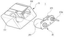
도 1은 본 발명의 바람직한 실시 예에 따른 약물 주입 펌프를 나타내는 사시도,
도 2는 도 1에 도시된 약물 주입 펌프를 다른 방향에서 바라본 모습을 나타내는 사시도,
도 3은 도 1에 도시된 약물 주입 펌프를 나타내는 분리 사시도,
도 4는 도 1에 도시된 약물 주입 펌프의 카트리지를 나타내는 사시도,
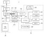
도 5는 도 1에 도시된 약물 주입 펌프를 나타내는 구성도,
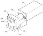
도 6은 도 4에 도시된 펌프 모듈이 구동 모터에 결합한 모습을 나타내는 사시도,
도 7은 도 6에 도시된 펌프 모듈의 내부 구성을 나타내는 사시도,
도 8과 도 9는 각각 도 6에 도시된 펌프 모듈의 동작을 설명하기 위한 도면,
도 10은 도 6 내지 도 9에 도시된 펌프 모듈의 변형 예를 나타내는 사시도,
도 11은 도 10에 도시된 펌프 모듈의 내부 구조를 나타내는 사시도,
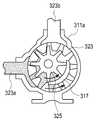
도 12 내지 15는 도 10에 도시된 펌프 모듈의 동작을 순차적으로 나타내는 도면,
도 16 내지 도 18은 도 10에 도시된 펌프 모듈의 변형 예로서, 외접 기어 펌프의 동작을 순차적으로 나타내는 도면.1 is a perspective view showing a drug infusion pump according to a preferred embodiment of the present invention,
FIG. 2 is a perspective view showing a state in which the drug infusion pump shown in FIG. 1 is viewed from another direction;
FIG. 3 is an exploded perspective view showing the drug infusion pump shown in FIG. 1,
FIG. 4 is a perspective view showing the cartridge of the drug infusion pump shown in FIG. 1,
FIG. 5 is a view showing the configuration of the drug infusion pump shown in FIG. 1;
FIG. 6 is a perspective view showing a state where the pump module shown in FIG. 4 is coupled to a drive motor,
7 is a perspective view showing the internal structure of the pump module shown in FIG. 6,
FIGS. 8 and 9 are views for explaining the operation of the pump module shown in FIG. 6,
10 is a perspective view showing a modification of the pump module shown in Figs. 6 to 9, Fig.
11 is a perspective view showing the internal structure of the pump module shown in FIG. 10,
12 to 15 are views sequentially showing the operation of the pump module shown in FIG. 10,
Figs. 16 to 18 are diagrams showing a variation of the pump module shown in Fig. 10 and sequentially showing the operation of the external gear pump. Fig.
이하 본 발명의 바람직한 실시 예를 첨부된 도면을 참조하여 상세히 설명하면 다음과 같다. 본 발명을 설명함에 있어서, 관련된 공지기능 혹은 구성에 대한 구체적인 설명이 본 발명의 요지를 불필요하게 흐릴 수 있다고 판단되는 경우 그 상세한 설명을 생략한다.Hereinafter, preferred embodiments of the present invention will be described in detail with reference to the accompanying drawings. In the following description of the present invention, a detailed description of known functions and configurations incorporated herein will be omitted when it may make the subject matter of the present invention rather unclear.
도 1 내지 도 5에 도시된 바와 같이, 본 발명의 바람직한 실시 예에 따른 약물 주입 펌프(1)는 본체(10)와, 상기 본체(10)에 착탈 가능하게 제공된 카트리지 모듈(20)을 구비한다. 이때, 상기 카트리지 모듈(20)은 펌프 모듈(215)과 약물 카트리지(213)를 포함하며, 상기 본체(10)는 상기 펌프 모듈(215)을 구동하기 위한 구동 모터(123)와, 상기 약물 주입 펌프(1)의 전반을 제어하기 위한 프로세서(121)를 포함한다.1 to 5, a
상기 본체(10)는 일면에 제공되는 디스플레이(111)와 버튼(113), 측면으로 제공된 커넥터(115)를 구비함으로써, 내장된 배터리(129)를 충전할 수 있다. 또한, 상기 약물 주입 펌프(1)는 약물 주입 시점에서, 주입량, 온도/습도 등의 날씨 정보 등을 저장할 수 있으며, 이렇게 저장된 정보는 상기 커넥터(115)를 통해 개인용 컴퓨터 등으로 전달될 수 있다. 상기 디스플레이(111)와 버튼(113)은 상기 약물 주입 펌프(1)를 조작하는 데 있어 출력 장치와 입력 장치로 활용된다. 상기 본체(10)의 다른 측면에는 상기 카트리지 모듈(20)을 수용하기 위한 수용홈들(117, 119)이 형성되어 있다. 본 발명의 구체적인 실시 예에서, 상기 수용홈들(117, 119)은 상기 카트리지 모듈(20)의 펌프 모듈(215)과 약물 카트리지(213)를 각각 독립적으로 수용할 수 있게 구성되어 있다.The
한편, 상기 본체(10)는 구동 모터(123)와 커플러(125), 무선통신 모듈(127), 스피커(131), 모터 드라이버(133), 부하 감지 센서(135) 등을 구비할 수 있다.The
상기 구동 모터(123)는 상기 펌프 모듈(215)을 구동하기 위한 것으로서, 서보 모터나 스텝 모터, 솔레노이드 등 작동 변위를 정밀하게 제어할 수 있는 구동 장치들 중 하나로 구성됨이 바람직하다. 상기 구동 모터(123)의 구동축(124; 도 8에 도시됨)에는 상기 펌프 모듈(215)의 피동축(217)이 결합하는데, 이때, 상기 피동축(217)은 커플러(125)를 통해 상기 구동축(124)에 결합한다. 상기 구동축(124)에 결합함으로써, 상기 피동축(217)은 상기 구동축(124)과 동일한 회전축(rotation axis)(R)을 중심으로 함께 회전할 수 있으며, 상기 회전축(R) 방향을 따라 직선 왕복 운동할 수도 있다. 또한, 상기 피동축(217)은 상기 커플러(125)를 통해 상기 구동축(124)에 결합된 구성이 예시되지만, 상기 구동축(124)과 피동축(217) 사이에는 별도의 감속 모듈이 제공될 수도 있다.The
상기 무선통신 모듈(127)은 상기 약물 주입 펌프(1)를 이동통신 단말기 등의 휴대 통신기기, 개인용 컴퓨터, 혈당 센서 등과 접속할 수 있게 한다. 상기 무선통신 모듈(127)이 혈당 센서에 접속한다면, 혈당 센서에서 검출되는 환자의 혈당 수치에 따라 약물의 주입 여부와 주입량을 조정할 수 있을 것이다. 또한, 혈당 센서에서 검출된 수치, 약물 주입 당시의 주입량 등의 정보는 개인용 컴퓨터나 휴대 통신기기로 저장하거나 담당 의사에게 실시간으로 전달될 수 있다. 또한, 담당 의사는 수신된 환자의 질환 정보, 약물 주입량 및 환경 정보 등을 참고하여 필요에 따라 새로운 처방을 입력, 전송할 수도 있을 것이다.The
상기 배터리(129)는 상기 약물 주입 펌프(1)의 작동을 위한 전원을 제공하게 되며, 상기 커넥터(115)를 통해 충전할 수 있다. 상기 스피커(131)는 경고음 등 음향 신호를 발생하거나, 상기 약물 주입 펌프(1)의 조작에 따른 단계적으로 사용법을 안내하는 음향을 출력할 수 있다. 상기 모터 드라이버(133)는 기 입력된 프로그램 및 상기 프로세서(121)의 제어에 따라 상기 구동 모터(123)를 작동시키는 구동 신호를 발생시킨다.The
상기 부하 감지 센서(135)는 상기 구동축(124) 또는 구동 모터(123)에 작용하는 부하의 변화를 감지함으로써, 상기 약물 주입 펌프(1) 작동 과정에서 약물의 흐름 경로의 협착, 폐쇄 등 이상 작동 현상을 검출하게 된다. 상기 부하 감지 센서(135)로는 홀 센서(hall effect sensor)나 포토 센서(photo sensor)와 같은 광학 센서가 이용될 수 있다. 상기 부하 감지 센서(135)가 상기 구동축(124) 또는 구동 모터(123)에서 이상 작동 현상을 감지하면, 상기 프로세서(121)는 상기 구동 모터(123)의 작동을 중단하고 경고 신호 등을 발생하도록 제어하게 된다.The
상기 카트리지 모듈(20)의 약물 카트리지(213)는 약물, 예를 들면, 인슐린제를 저장하며, 탄성체 재질로 제작될 수 있다. 탄성체 재질로 제작된 상기 약물 카트리지(213)는 저장된 약물을 일정하게 가압하게 된다. 따라서 상기 펌프 모듈(215) 동작시, 상기 약물 카트리지(213)에 저장된 약물이 상기 펌프 모듈(215)로 원활하게 공급될 수 있다. 물론, 탄성체 재질로 상기 약물 카트리지(213)를 제작하지 않더라도, 기계적인 구조를 이용하여 상기 약물 카트리지(213)에 저장된 약물을 가압할 수도 있을 것이다. 예를 들어, 통상적인 주사기 구조에 이용되는 밀대(plunger)와 스프링(spring)을 상기 약물 카트리지(213) 내부에 배치하여, 상기 약물 카트리지(213)에 저장된 약물을 가압할 수 있다. 또한, 상기 약물 카트리지(213)의 내부에 탄성 변형 가능한 격막 구조를 설치하여, 상기 약물 카트리지(213)의 내부 공간을 기체 챔버와 약물 챔버로 분할할 수도 있을 것이다. 이 경우, 기체 챔버를 기체로 충전하여 기체 챔버만으로 상기 약물 카트리지(213)의 내부 공간을 완전히 채운 후, 약물 챔버에 약물을 주입하면 상기 약물 카트리지(213) 내부에서 약물 챔버에 주입된 약물은 기체 챔버의 압력에 의해 가압될 것이다. 이러한 격막 구조는 자체적으로 탄성 변형 가능한 필름 재질로 이루어질 수 있으며, 주름관(bellows) 구조를 이용하여 구성할 수도 있을 것이다.The
상기 약물 카트리지(213)는 공급 튜브(213a)를 통해 상기 펌프 모듈(215)로 연결된다. 아울러, 상기 카트리지 모듈(20)은 상기 펌프 모듈(215)에 연결된 주사 튜브(213b)를 구비한다. 상기 주사 튜브(213b)는 상기 펌프 모듈(215)의 배출 포트(223b; 도 6에 도시됨)에 연결되어 상기 펌프 모듈(215) 동작에 따라 배출되는 약물을 환자에게 공급하게 된다.The
상기 카트리지 모듈(20)의 펌프 모듈(215)은 메모리(221)와 접속 단자(219)를 더 구비할 수 있다. 상기 메모리(221)는 읽기 전용 메모리 또는 읽기/쓰기 메모리로 구성될 수 있다. 상기 약물 카트리지(213)에 저장된 약물의 유효기간, 정품 인증 코드, 구동 모터의 구동 조건 등, 제조 과정에서 입력 가능한 정보들만을 저장한다면, 상기 메모리(221)는 읽기 전용 메모리로 구성될 수 있다. 또한, 상기 메모리(221)가 읽기/쓰기 메모리로 구성된다면, 환자의 질환에 따라 의사의 처방전 입력 및 갱신이 가능하다. 상기 메모리(221)가 읽기/쓰기 메모리로 구성된다 하더라도, 제조 과정에서 입력된 정보들은 수정될 수 없도록 설정되어야 할 것이다.The
상기 접속 단자(219)는 상기 메모리(221)와 연결되어 상기 메모리(221)를 상기 프로세서(121)에 접속시키게 된다. 따라서 상기 카트리지 모듈(20)이 상기 본체(10)에 장착되면, 상기 프로세서(121)는 상기 메모리(221)에 저장된 정보를 판독할 수 있으며, 상기 메모리(221)에 저장된 정보에 따라 상기 구동 모터(123)의 구동 조건을 설정할 수 있다.The
상기 펌프 모듈(215)과 약물 카트리지(213)를 하나의 모듈로 구성하기 위해, 상기 카트리지 모듈(20)은 케이스 부재(211)를 구비할 수 있다. 즉, 상기 펌프 모듈(215)과 상기 약물 카트리지(213)가 상기 케이스 부재(211)에 고정되는 것이다. 상기 케이스 부재(211)는 상기 약물 카트리지(213)를 적어도 부분적으로 감싸게 제공될 수 있으며, 상기 본체(10)에 장착된 상태에서는 외부로 일부 노출될 수도 있다. 상기 약물 카트리지(213)와 케이스 부재(211) 각각은 적어도 부분적으로 투명한 재질로 제작됨이 바람직하다. 이는 상기 약물 카트리지(213)에 남아있는 약물의 양을 환자가 쉽게 확인할 수 있게 하기 위함이다.The
이하에서는 도 6 내지 도 9를 참조하여, 상기 펌프 모듈(215)의 구조 및 상기 펌프 모듈(215)과 구동 모터(123)의 결합 구조를 살펴보기로 한다. 도 6 내지 도 10에 도시된 펌프 모듈(215)은 피스톤 부재(217b)의 직선 왕복 운동에 의해 약물을 흡입, 배출하게 된다. 우선, 상기 피동축(217)은 상기 펌프 모듈(215) 상에서 회전 가능함과 아울러 직선 왕복 운동 가능하게 장착된다. 상기 커플러(125)를 통해 상기 구동축(124)에 결합함에 있어서, 상기 피동축(217)은 회전 방향에서 상기 커플러(125)에 고정됨과 아울러, 상기 커플러(125)에 대하여 상기 회전축(R) 방향으로 직선 왕복 운동 가능하게 결합한다.Hereinafter, the structure of the
상기 펌프 모듈(215)은 상기 피동축(217)과 아울러 내부에 고정된 라이너(liner)(223)를 구비한다. 상기 라이너(223)는 상기 회전축(R) 방향으로 연장된 챔버(chamber)(223d)를 구비하며, 일단이 개방되어 있다. 상기 라이너(223)는 유입 포트(223a)와 배출 포트(223b)를 각각 구비하며, 상기 라이너(223)의 일부분이 상기 펌프 모듈(215)의 외부로 돌출될 수 있다. 상기 라이너(223)의 일부분이 상기 펌프 모듈(215)의 외부로 돌출된다면, 상기 유입/배출 포트(223a, 223b)는 상기 펌프 모듈(215)의 외부에 노출된 상태로 배치될 수 있다. 상기 유입 포트(223a)는 상기 공급 튜브(213a)를 통해 상기 약물 카트리지(213)에 연결되며, 상기 배출 포트(223b)에는, 앞서 언급한 바와 같이, 상기 주사 튜브(213b)가 연결되어 있다.The
상기 피동축(217)의 일단은 상기 커플러(125)에 결합한다. 대체로 상기 피동축(217)은 원형의 단면을 가지고 있어 상기 펌프 모듈(215)에 회전 가능하게 배치되지만, 상기 커플러(125)에 결합하는 부분에서는 외주면의 적어도 일부분이 평면으로 형성되는 것이 바람직하다. 이는 상기 피동축(217)이 상기 펌프 모듈(215) 내에서 회전 가능하면서, 회전 방향에서 상기 커플러(125)에 고정되게 하기 위함이다.One end of the driven
상기 피스톤 부재(217b)는 상기 피동축(217)의 타단에 제공된다. 상기 피스톤 부재(217b)는 상기 피동축(217)의 타단에서 상기 회전축(R) 방향으로 연장되며, 상기 라이너(223)의 챔버(223d) 내부에 수용된다. 상기 피스톤 부재(217b)는, 상기 피동축(217)과 함께, 상기 챔버(223d) 내에서 회전함과 동시에 상기 회전축(R) 방향으로 직선 왕복 운동하게 된다. 상기 피스톤 부재(217b)의 단부에는 노치부(notch portion)(217c)가 형성되어 있다. 상기 유입 포트(223a)와 배출 포트(223b)는 대체로 상기 피스톤 부재(217b)의 외주면에 의해 폐쇄되어 상기 챔버(223d)와 연결되지 않지만, 상기 피스톤 부재(217b)의 회전 위치에 따라 상기 챔버(223d)에 연결될 수 있다. 즉, 상기 피스톤 부재(217b)의 회전에 따라 상기 노치부(217c)가 상기 유입 포트(223a)와 배출 포트(223b)를 번갈아가며 상기 챔버(223d)에 연결하는 것이다.The
상기 유입 포트(223a)가 상기 챔버(223d)에 연결된 구간에서 회전하는 상기 피동축(217)은 상기 라이너(223)로부터 멀어지는 방향, 즉, 상기 피스톤 부재(217a)가 상기 챔버(223d)로부터 이탈하는 방향으로 이동한다. 이때, 상기 배출 포트(223b)는 상기 피스톤 부재(217b)의 외주면에 의해 폐쇄된다. 따라서 상기 약물 카트리지(213)에 저장된 약물은, 압력이 낮아진 상기 챔버(223d)의 내부로 유입된다. 상기 배출 포트(223b)가 상기 챔버(223d)에 연결된 구간에서 회전하는 상기 피스톤 부재(217b)는 상기 라이너(223)에 접근하는 방향, 즉, 상기 피스톤 부재(217a)가 상기 챔버(223d)로부터 잠입하는 방향으로 직선 이동한다. 이때, 상기 유입 포트(223a)는 상기 피스톤 부재(217b)의 외주면에 의해 폐쇄된다. 따라서 상기 챔버(223d)의 내부 압력이 증가하면서, 상기 챔버(223d)의 내부에 유입된 약물은 상기 배출 포트(223b)를 통해 배출된다.The driven
상기 피스톤 부재(217b)의 회전을 직선 왕복 운동으로 전환하기 위하여, 상기 펌프 모듈(215)은 탄성 부재(227)와 경사면들(217a, 223c)을 구비한다. 상기 탄성 부재(227)는 상기 펌프 모듈(215)의 내부에서 상기 피동축(217)을 상기 라이너(223)에 접근하는 방향으로 작용하는 탄성력을 제공하게 된다. 상기 피동축(217)의 외주면에는 상기 탄성 부재(227)의 한 단부를 지지하는 지지 리브(217d)가 형성된다. 상기 지지 리브(217d)는 상기 피동축(217)의 둘레를 감싸는 링 형상으로 형성될 수 있다. 상기 경사면들은 상기 피동축(217)의 타단에 형성되는 제1 경사면(217a)과, 상기 라이너(223)의 개방된 단부에 형성된 제2 경사면(223c)으로 이루어진다. 상기 제1, 제2 경사면(217a, 223c)은 각각 상기 회전축(R)에 대하여 경사지게 형성되며, 바람직하게는 상기 회전축(R)에 대하여 동일한 각도로 경사지게 형성된다. 상기 탄성 부재(227)와 경사면들(217a, 223c)의 구성에 의해, 상기 피동축(217)은 상기 구동축(124)과 함께 회전하면서, 상기 펌프 모듈(215) 내에서 직선 왕복 운동하게 된다. 도 8에 도시된 바와 같이, 상기 제1, 제2 경사면들(217a, 223c)이 서로 동일한 방향으로 정렬된 위치에서 상기 피동축(217)은 상기 탄성 부재(227)의 탄성력에 의해 상기 라이너(223) 방향으로 전진하여 상기 제1, 제2 경사면들(217a, 223c)을 서로 밀착시킨다. 도 8에 도시된 위치로부터 상기 피동축(217)이 180도 각도만큼 회전하면, 상기 제1, 제2 경사면(217a, 223c)은 서로에 대하여 역방향으로 경사지게 정렬된다. 따라서, 도 9에 도시된 바와 같이 상기 피동축(217)은 상기 라이너(223)로부터 멀어진 방향으로 이동하게 된다. 결국, 상기 피동축(217)은 상기 구동축(124)과 함께 회전하면서, 도 8과 도 9에 각각 도시된 위치 사이에서 직선 왕복 운동하게 된다.In order to convert the rotation of the
상기 피동축(217)이 회전 운동과 동시에 직선 왕복 운동함에 따라, 상기 피스톤 부재(217b) 또한 상기 챔버(223d) 내에서 회전 운동 및 직선 왕복 운동하게 된다.As the driven
도 8을 참조하면, 상기 피스톤 부재(217b)가 상기 챔버(223d)의 내부로 완전히 잠입한 상태에서, 또는, 상기 챔버(223d)의 내부로 잠입하는 과정에서, 상기 유입 포트(223a)는 폐쇄되고 상기 노치부(217c)에 의해 상기 배출 포트(223b)가 개방된다. 따라서 상기 챔버(223d) 내부의 약물은 상기 배출 포트(223b)와 주사 튜브(213b)를 통해 환자에게 투여된다. 도 9에 도시된 바와 같이 상기 피스톤 부재(217b)가 상기 챔버(223d)로부터 벗어나는 방향으로 이동한 상태에서, 또는, 상기 챔버(223d)로부터 벗어나는 방향으로 이동하는 과정에서, 상기 배출 포트(223b)는 폐쇄되고, 상기 노치부(217c)에 의해 상기 유입 포트(223a)가 개방된다. 이때, 상기 챔버(223d)의 내부 압력이 낮아지면서 상기 약물 카트리지(213)에 저장된 약물이 상기 챔버(223d)의 내부로 유입된다.Referring to FIG. 8, in a state where the
결과적으로, 상기 피스톤 부재(217b)가 상기 챔버(223d) 내에서 회전 운동함과 동시에 직선 왕복 운동을 하면서 펌핑 동작을 하게 되고, 상기 챔버(223d)의 내부 압력이 증가하거나 감소하게 된다. 따라서 상기 약물 카트리지(213)에 저장된 약물은 번갈아가며 제1의 경로, 즉, 상기 공급 튜브(213a)를 통해 상기 챔버(223d)로 유입되고, 제2의 경로, 즉, 상기 주사 튜브(213b)를 통해 상기 챔버(223d)로부터 배출된다.As a result, the
도 10과 도 11은 도 6에 도시된 펌프 모듈의 변형된 예를 도시하고 있다.10 and 11 show a modified example of the pump module shown in Fig.
도 6에 도시된 펌프 모듈(215)은 구동축(124)의 회전 운동을 피스톤 부재(217b)의 직선 왕복 운동으로 전환하여 펌핑 동작을 수행한 반면에, 도 10과 도 11에 도시된 펌프 모듈(315)은 기어 펌프를 이용한 것이다.The
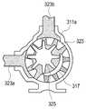
상기 펌프 모듈(315)은 메인 케이싱(311a)과 보조 케이싱(311b)이 결합하여 이루어지는 케이싱(311)의 내부에 한 쌍의 기어들(323, 325)을 수용한 것이다. 상기 메인 케이싱(311a) 또는 보조 케이싱(311b) 중 하나에는 약물의 유입, 배출을 위한 유입/배출 포트(323a, 323b)들이 배치된다. 도 10에 도시된 구조에서는 상기 보조 케이싱(311b)에 상기 유입/배출 포트(323a, 323b)들이 배치된 구성이 예시되어 있다. 상기 케이싱(311)의 내부에는 한 쌍의 기어들(323, 325)이 서로 맞물리게 배치되어 있다. 상기 기어들 중 제1 기어(323)의 치형들이 제2 기어(325)의 치형들로부터 이탈하는 위치(이하, '제1 위치'라 함)에 상기 유입 포트(323a)가 상기 케이싱(311)의 내부 공간에 연결되고, 제1 기어(323a)의 치형들이 제2 기어(325)의 치형들과 다시 맞물리는 위치(이하, '제2 위치'라 함)에 상기 배출 포트(323b)가 상기 케이싱(311)의 내부 공간에 연결된다. 따라서 상기 제1 위치에서는 상기 유입 포트(323a)를 통해 상기 제1, 제2 기어(323, 325) 각각의 치형들 사이 공간으로 약물이 유입되며, 상기 제2 위치에서는 상기 제1, 제2 기어(323, 325) 각각의 치형들 사이 공간에 유입된 약물이 강제로 상기 배출 포트(323b)를 통해 배출된다.The
상기와 같은 기어 펌프는 내접 기어 펌프 또는 외접 기어 펌프로 이루어질 수 있다. 도 12 내지 도 15는 내접 기어 펌프의 동작을 순차적으로 도시하고 있으며, 도 16 내지 도 18은 외접 기어 펌프의 동작을 순차적으로 도시하고 있다.The gear pump may be an internal gear pump or an external gear pump. Figs. 12 to 15 sequentially show the operation of the internal gear pump, and Figs. 16 to 18 sequentially show the operation of the external gear pump.
도 12 내지 도 15를 참조하면, 제1 기어(323)는 내주면에 기어 치형들이 형성되며, 제2 기어(325)는 외주면에 기어 치형들이 형성되어 있다. 상기 제1 기어(323)는 상기 케이싱(311)의 내부에 수용되어 상기 제2 기어(325)와 맞물려 회전하고, 상기 제2 기어(325)는 상기 피동축(217)에 결합하여 상기 구동 모터(123)의 작동에 의해 회전한다. 이때, 상기 제1 기어(323)의 내경은 상기 제2 기어(325)의 외경보다 크게 형성된다. 상기 케이싱(311)의 내부 공간에서 상기 제1, 제2 기어들(323, 325)의 치형이 서로 맞물리지 않은 영역에는 격막(317)이 배치된다. 상기 격막(317)에 의해 상기 유입 포트(323a)와 배출 포트(323b) 사이는 대체로 격리된 상태를 유지하게 된다. 상기 격막(317)은 상기 메인 케이싱(311a)과 보조 케이싱(311b) 중 어느 하나의 내벽에 형성될 수 있다. 상기 격막(317)이 배치됨에 따라, 상기 유입 포트(323a)로부터 배출 포트(323b)로의 약물 이송은 상기 제1, 제2 기어(323, 325)의 회전에 의해서만 가능하게 된다.Referring to FIGS. 12 to 15, gear teeth are formed on the inner circumferential surface of the
도 12 내지 도 15에 도시된 구성에서, 상기 제1, 제2 기어들(323, 325)은 각각 반 시계 방향으로 회전하게 되며, 상기 제1, 제2 기어들(323, 325)의 회전에 따라, 상기 유입 포트(323a)로 유입된 약물은 상기 제1, 제2 기어들(323, 325)의 치형들 사이에 유입되어 상기 격막(317)을 지나 상기 배출 포트(323b)로 유출된다. 이때, 상기 제1 위치에서는 상기 제1 기어(323)의 치형들이 상기 제2 기어(325)의 치형들로부터 이탈하면서 치형들 사이의 공간이 확장된다. 치형들 사이의 공간이 확장되는 만큼 압력 또한 낮아지면서 약물의 유입을 강제하게 된다. 이때, 상기 약물 카트리지(213)가 탄성체 재질로 제작되어 내부에 저장된 약물을 가압한다면, 상기 펌프 모듈(315)로의 약물 유입이 더 활성화될 것이다. 상기 제2 위치에서는 상기 제1 기어(323)의 치형들이 다시 상기 제2 기어(325)의 치형들과 맞물리게 된다. 따라서 상기 제2 위치에서 약물은 치형들 사이의 공간에서 강제로 배출되어 상기 배출 포트(323b)를 통해 상기 주사 튜브(213b)로 흐르게 된다.12 to 15, the first and
도 16 내지 도 18을 참조하면, 외접 기어 펌프는 한 쌍의 태양 기어들(333, 335)을 서로 맞물리게 구성한 것으로서, 상기 기어들 중 제1의 기어(333)가 상기 피동축(217)에 결합하여 회전하며, 제2의 기어(335)는 상기 제1 기어(333)와 맞물려 회전하게 된다. 상기 제1 위치, 즉, 상기 유입 포트(323a)에 인접한 위치에서, 상기 제1 기어(333)의 치형들이 상기 제2 기어(335)의 치형들로부터 이탈함에 따라 상기 유입 포트(323a)를 통해 약물이 상기 케이싱(311) 내부로 유입된다. 유입된 약물은 상기 제1, 제2 기어(333, 335) 각각의 치형들 사이 공간에 수용되며, 상기 제1, 제2 기어(333, 335)의 회전에 따라 상기 배출 포트(323b)에 인접한 상기 제2 위치까지 이송된다. 상기 제2 위치에서 상기 제1 기어(333)의 치형들이 상기 제2 기어(335)의 치형들에 다시 맞물림에 따라 치형들 사이의 약물은 강제로 배출되어 상기 배출 포트(323b)를 통해 상기 주사 튜브(213b)로 흐르게 된다.
16 to 18, the external gear pump has a pair of sun gears 333 and 335 interlocked with each other. The
종래의 모터 구동 주사기 방식(motorized syringe plunger type), 솔레노이드(solenoid) 또는 스텝 모터(step motor)와 래칫 기어(ratchet gear)를 조합한 방식과 비교할 때, 본 발명에 따른 약물 주입 펌프는 피스톤 부재 또는 기어들을 이용하여 펌프 모듈을 구성함으로써 구동 공간을 줄일 수 있게 된다. 따라서 동일한 크기의 약물 주입 펌프라면 본 발명에 따른 약물 주입 펌프는 종래의 약물 주입 펌프보다 약물 저장 용량을 더 확장할 수 있게 된다. 또한, 소모성 부품인 카트리지 모듈의 구성을 단순화하여, 교체에 따른 사용자, 즉, 환자의 경제적 부담을 경감할 수 있다. 더욱이, 카트리지 모듈을 약물 주입 펌프의 본체에 장착함에 있어서는 별도로 리드 스크루의 위치를 조정하는 과정이 불필요하며, 형상에 맞게 제공된 수용홈에 카트리지 모듈을 용이하게 장착할 수 있다. 따라서 환자가 간편하게 사용할 수 있게 된다.
Compared with a combination of a motorized syringe plunger type, a solenoid or a step motor and a ratchet gear, the drug infusion pump according to the present invention can be applied to a piston member The pump module can be constructed using the gears, thereby reducing the driving space. Therefore, if the drug injection pump of the same size is used, the drug injection pump according to the present invention can further expand the drug storage capacity than the conventional drug injection pump. Further, the configuration of the cartridge module, which is a consumable part, can be simplified, and the economic burden on the user, that is, the patient, can be reduced. Further, when the cartridge module is mounted on the main body of the drug infusion pump, it is unnecessary to separately adjust the position of the lead screw, and the cartridge module can be easily mounted on the receiving groove provided according to the shape. Therefore, the patient can be used easily.
이상, 본 발명의 상세한 설명에서는 구체적인 실시 예에 관해서 설명하였으나, 본 발명의 범위에서 벗어나지 않는 한도 내에서 여러 가지 변형이 가능함은 당해 분야에서 통상의 지식을 가진 자에게 있어서 자명하다 할 것이다.While the present invention has been particularly shown and described with reference to exemplary embodiments thereof, it is to be understood that the invention is not limited to the disclosed exemplary embodiments.
1: 약물 주입 펌프 10: 본체
20: 카트리지 모듈 123: 구동 모터
213: 카트리지 모듈 215: 펌프 모듈1: Drug injection pump 10: Body
20: Cartridge module 123: Drive motor
213: Cartridge module 215: Pump module
Claims (14)
Translated fromKorean구동 모터와 프로세서를 포함하는 본체; 및
펌프 모듈과 약물 카트리지를 포함하고, 상기 본체에 착탈 가능하게 제공된 카트리지 모듈을 구비하고,
상기 카트리지 모듈이 상기 본체에 장착됨에 따라, 상기 펌프 모듈 및 약물 카트리지가 상기 본체에 수용되고, 상기 펌프 모듈이 상기 구동 모터와 결합함을 특징으로 하는 약물 주입 펌프.
In the drug infusion pump,
A main body including a drive motor and a processor; And
A cartridge module including a pump module and a drug cartridge, the cartridge module being detachably provided in the main body,
Wherein the pump module and the drug cartridge are housed in the main body as the cartridge module is mounted to the main body, and the pump module is coupled to the drive motor.
The drug infusion pump according to claim 1, wherein the cartridge module further comprises a memory and a connection terminal for connecting the memory to the processor.
The drug infusion pump according to claim 2, wherein the memory is a read-only memory that stores an identification code of the cartridge module, an effective period of the drug stored in the drug cartridge, an activation code, and driving conditions of the driving motor.
The drug infusion pump according to claim 3, wherein, when the cartridge module is mounted on the main body, the processor reads the information stored in the memory and sets driving conditions of the driving motor.
The drug infusion pump according to claim 2, wherein the memory is a read / write memory capable of updating a prescription input according to a disease of a patient.
The drug infusion pump according to claim 5, wherein, when the cartridge module is mounted on the main body, the processor reads information stored in the memory and sets driving conditions of the driving motor.
상기 구동 모터는 구동축(driving shaft)에 고정된 커플러(coupler)를, 상기 펌프 모듈은 상기 커플러에 결합 가능한 피동축을 각각 포함하고,
상기 피동축은 상기 커플러에 결합하여 상기 구동축과 함께 회전함을 특징으로 하는 약물 주입 펌프.
The method according to claim 1,
Wherein the drive motor includes a coupler fixed to a driving shaft, and the pump module includes a driven shaft engageable with the coupler,
Wherein the driven shaft is coupled to the coupler and rotated together with the drive shaft.
상기 피동축의 회전축(rotation axis) 방향으로 연장된 챔버(chamber)를 제공하는 라이너(liner); 및
상기 피동축의 단부로부터 연장되어 상기 챔버 내에 수용되는 피스톤 부재를 더 포함하고,
상기 피동축이 상기 구동축과 함께 회전함에 따라, 상기 피스톤 부재가 상기 챔버 내에서 상기 회전축 방향으로 직선 왕복 운동함을 특징으로 하는 약물 주입 펌프.
8. The pump module according to claim 7,
A liner providing a chamber extending in the direction of a rotation axis of the driven shaft; And
And a piston member extending from an end of the driven shaft and received in the chamber,
Wherein the piston member linearly reciprocates in the rotation axis direction in the chamber as the driven shaft rotates together with the drive shaft.
상기 피동축의 단부에 제공되며 상기 회전축에 대하여 경사지게 형성된 제1 경사면;
상기 라이너의 단부에 제공되며 상기 제1 경사면과 상응하게 형성된 제2 경사면; 및
상기 제1, 제2 경사면이 밀착하는 방향으로 탄성력을 제공하는 탄성 부재를 더 포함하고,
상기 피동축이 회전하면 상기 제1 경사면이 상기 제2 경사면에 대면한 상태로 회전함으로써, 상기 피동축 및 피스톤 부재가 직선 왕복 운동함을 특징으로 하는 약물 주입 펌프.
9. The pump module according to claim 8,
A first inclined surface provided at an end of the driven shaft and formed to be inclined with respect to the rotation axis;
A second inclined surface provided at an end of the liner and corresponding to the first inclined surface; And
Further comprising an elastic member for providing an elastic force in a direction in which the first and second inclined surfaces are in close contact with each other,
Wherein when the driven shaft rotates, the first inclined surface rotates while facing the second inclined surface, whereby the driven shaft and the piston member reciprocate linearly.
9. The apparatus of claim 8, wherein as the piston member reciprocates linearly in the chamber, alternately, the drug stored in the drug cartridge flows through the first path into the chamber and enters the chamber through the second path, Wherein the medicament is discharged.
상기 펌프 모듈은 적어도 한 쌍의 기어들을 케이싱 내에 수용하는 내접 기어 펌프 또는 외접 기어 펌프를 더 포함하고,
상기 기어들 중 제1의 기어가 상기 피동축에 결합하여 상기 피동축과 함께 회전함에 따라, 제1의 경로를 통해 상기 약물 카트리지에 저장된 약물이 상기 케이싱으로 유입되고, 상기 케이싱에 유입된 약물이 제2의 경로를 통해 배출됨을 특징으로 하는 약물 주입 펌프.
8. The method of claim 7,
Wherein the pump module further comprises an internal gear pump or an external gear pump for accommodating at least a pair of gears in a casing,
As the first gear of the gears engages with the driven shaft and rotates together with the driven shaft, the drug stored in the drug cartridge flows into the casing through the first path, and the drug introduced into the casing And is discharged through a second path.
The drug infusion pump according to claim 1, wherein the main body further comprises a wireless communication module, and is connected to the blood glucose sensor or the portable communication device through the wireless communication module.
The drug infusion pump according to claim 1, wherein the main body further comprises a load sensor for sensing a load acting on the operation of the driving motor.
Priority Applications (3)
| Application Number | Priority Date | Filing Date | Title |
|---|---|---|---|
| KR1020130024923AKR20140110496A (en) | 2013-03-08 | 2013-03-08 | Drug infusion pump |
| US14/173,262US20140257178A1 (en) | 2013-03-08 | 2014-02-05 | Drug infusion pump |
| EP14155857.7AEP2774636A3 (en) | 2013-03-08 | 2014-02-20 | Drug infusion pump |
Applications Claiming Priority (1)
| Application Number | Priority Date | Filing Date | Title |
|---|---|---|---|
| KR1020130024923AKR20140110496A (en) | 2013-03-08 | 2013-03-08 | Drug infusion pump |
Publications (1)
| Publication Number | Publication Date |
|---|---|
| KR20140110496Atrue KR20140110496A (en) | 2014-09-17 |
Family
ID=50150607
Family Applications (1)
| Application Number | Title | Priority Date | Filing Date |
|---|---|---|---|
| KR1020130024923ACeasedKR20140110496A (en) | 2013-03-08 | 2013-03-08 | Drug infusion pump |
Country Status (3)
| Country | Link |
|---|---|
| US (1) | US20140257178A1 (en) |
| EP (1) | EP2774636A3 (en) |
| KR (1) | KR20140110496A (en) |
Cited By (7)
| Publication number | Priority date | Publication date | Assignee | Title |
|---|---|---|---|---|
| KR101689233B1 (en) | 2016-08-05 | 2017-01-02 | 주식회사 세종메디칼 | Medicinal fluid flow indicator and fluid infusion pump having the same |
| KR20180018116A (en)* | 2016-08-12 | 2018-02-21 | 주식회사 동방메디컬 | Drug cartridge and drug infusion device including the same |
| KR20180076071A (en)* | 2016-12-27 | 2018-07-05 | 최규동 | Injection Appartus with Gear Pump |
| KR102204634B1 (en)* | 2020-09-23 | 2021-01-19 | 이대로 | Insulin Infusion Device |
| KR20210075716A (en)* | 2019-12-13 | 2021-06-23 | 주식회사 휴온스메디컬 | Drug injection device |
| CN113260398A (en)* | 2019-02-18 | 2021-08-13 | 泰尔茂株式会社 | Liquid medicine feeding device |
| WO2022186548A1 (en)* | 2021-03-02 | 2022-09-09 | 주식회사 바리센 | Driving control mechanism and drug injection apparatus using same |
Families Citing this family (14)
| Publication number | Priority date | Publication date | Assignee | Title |
|---|---|---|---|---|
| US9151646B2 (en) | 2011-12-21 | 2015-10-06 | Deka Products Limited Partnership | System, method, and apparatus for monitoring, regulating, or controlling fluid flow |
| US10228683B2 (en) | 2011-12-21 | 2019-03-12 | Deka Products Limited Partnership | System, method, and apparatus for monitoring, regulating, or controlling fluid flow |
| US9746093B2 (en) | 2011-12-21 | 2017-08-29 | Deka Products Limited Partnership | Flow meter and related system and apparatus |
| WO2014076519A1 (en)* | 2012-10-29 | 2014-05-22 | Debiotech S.A. | Extracorporeal blood treatment device |
| US9759343B2 (en) | 2012-12-21 | 2017-09-12 | Deka Products Limited Partnership | Flow meter using a dynamic background image |
| USD905848S1 (en)* | 2016-01-28 | 2020-12-22 | Deka Products Limited Partnership | Apparatus to control fluid flow through a tube |
| CN108697845B (en) | 2016-01-28 | 2021-09-17 | 德卡产品有限公司 | Apparatus for monitoring, regulating or controlling fluid flow |
| USD854145S1 (en) | 2016-05-25 | 2019-07-16 | Deka Products Limited Partnership | Apparatus to control fluid flow through a tube |
| US10646641B1 (en) | 2017-07-26 | 2020-05-12 | Micromo Electronics, Inc. | Liquid dispensing pump |
| USD847974S1 (en)* | 2017-09-12 | 2019-05-07 | Bioq Pharma Inc. | Two bottle enclosed desktop dispenser |
| CN109793963B (en)* | 2019-01-31 | 2023-11-28 | 深圳中科生物医疗电子有限公司 | Infusion pump with position-adjustable driving device |
| US12403247B2 (en)* | 2019-05-17 | 2025-09-02 | Medtrum Technologies Inc. | Drug infusion device |
| WO2021021596A1 (en) | 2019-07-26 | 2021-02-04 | Deka Products Limited Partnership | Apparatus for monitoring, regulating, or controlling fluid flow |
| USD964563S1 (en) | 2019-07-26 | 2022-09-20 | Deka Products Limited Partnership | Medical flow clamp |
Family Cites Families (6)
| Publication number | Priority date | Publication date | Assignee | Title |
|---|---|---|---|---|
| US7766873B2 (en)* | 1998-10-29 | 2010-08-03 | Medtronic Minimed, Inc. | Method and apparatus for detecting occlusions in an ambulatory infusion pump |
| US20080097291A1 (en)* | 2006-08-23 | 2008-04-24 | Hanson Ian B | Infusion pumps and methods and delivery devices and methods with same |
| US8579853B2 (en)* | 2006-10-31 | 2013-11-12 | Abbott Diabetes Care Inc. | Infusion devices and methods |
| EP2453972B1 (en)* | 2009-07-16 | 2014-01-15 | Medingo Ltd. | A device for accurate infusion of fluids |
| US8672873B2 (en)* | 2009-08-18 | 2014-03-18 | Cequr Sa | Medicine delivery device having detachable pressure sensing unit |
| US9381300B2 (en)* | 2010-09-24 | 2016-07-05 | Perqflo, Llc | Infusion pumps |
- 2013
- 2013-03-08KRKR1020130024923Apatent/KR20140110496A/ennot_activeCeased
- 2014
- 2014-02-05USUS14/173,262patent/US20140257178A1/ennot_activeAbandoned
- 2014-02-20EPEP14155857.7Apatent/EP2774636A3/ennot_activeWithdrawn
Cited By (8)
| Publication number | Priority date | Publication date | Assignee | Title |
|---|---|---|---|---|
| KR101689233B1 (en) | 2016-08-05 | 2017-01-02 | 주식회사 세종메디칼 | Medicinal fluid flow indicator and fluid infusion pump having the same |
| KR20180018116A (en)* | 2016-08-12 | 2018-02-21 | 주식회사 동방메디컬 | Drug cartridge and drug infusion device including the same |
| KR20180076071A (en)* | 2016-12-27 | 2018-07-05 | 최규동 | Injection Appartus with Gear Pump |
| CN113260398A (en)* | 2019-02-18 | 2021-08-13 | 泰尔茂株式会社 | Liquid medicine feeding device |
| US12274860B2 (en) | 2019-02-18 | 2025-04-15 | Terumo Kabushiki Kaisha | Drug solution delivery apparatus |
| KR20210075716A (en)* | 2019-12-13 | 2021-06-23 | 주식회사 휴온스메디컬 | Drug injection device |
| KR102204634B1 (en)* | 2020-09-23 | 2021-01-19 | 이대로 | Insulin Infusion Device |
| WO2022186548A1 (en)* | 2021-03-02 | 2022-09-09 | 주식회사 바리센 | Driving control mechanism and drug injection apparatus using same |
Also Published As
| Publication number | Publication date |
|---|---|
| US20140257178A1 (en) | 2014-09-11 |
| EP2774636A2 (en) | 2014-09-10 |
| EP2774636A3 (en) | 2015-06-24 |
Similar Documents
| Publication | Publication Date | Title |
|---|---|---|
| KR20140110496A (en) | Drug infusion pump | |
| US20080255517A1 (en) | Dual microcontroller-based liquid infusion system | |
| US7144384B2 (en) | Dispenser components and methods for patient infusion device | |
| TWI621458B (en) | Drug infusion device with safety interlock | |
| CN102149417B (en) | Dosing unit and ambulatory infusion device comprising dosing unit | |
| DK2391408T3 (en) | PORTABLE MEDICAL FLUID ADMINISTRATION WITH DRIVE SCREW LED CONNECTOR WITH CONTAINER STAMP | |
| ES2831604T3 (en) | Fluid Management Device and Operating Procedures | |
| CN103782298A (en) | System for optimizing a drug dosage regimen over time | |
| US11679205B2 (en) | High precision syringe with removable pump unit | |
| TW202412866A (en) | Systems and methods for substantially continuous intravenous infusion of the same or substantially the same medical fluid with fluid source replacements | |
| JP2007509647A (en) | Micropump for liquid drug delivery | |
| WO2010078073A1 (en) | Reservoir compartment adapter for infusion device | |
| KR101923267B1 (en) | Drug cartridge and drug infusion device including the same | |
| KR101955437B1 (en) | Infusion pump and liquid medicine infuser | |
| KR101347640B1 (en) | Cartridge-way infusion pump | |
| US20230122652A1 (en) | Flexible linkage for positive displacement pumps | |
| KR20180076071A (en) | Injection Appartus with Gear Pump | |
| US20230241296A1 (en) | Positive displacement pumping mechanism with double reservoir | |
| KR20130124424A (en) | Apparatus for supplying medicinal fluid | |
| KR102662719B1 (en) | Reservoir assembly and apparatus for infusing medical liquid comprising the same | |
| WO2021183489A1 (en) | High precision syringe with removable pump unit | |
| KR20200032307A (en) | Monitering and Management System for Pen Type Injection Appartus | |
| HK1223579B (en) | Drug infusion device with safety interlock |
Legal Events
| Date | Code | Title | Description |
|---|---|---|---|
| PA0109 | Patent application | Patent event code:PA01091R01D Comment text:Patent Application Patent event date:20130308 | |
| PG1501 | Laying open of application | ||
| A201 | Request for examination | ||
| PA0201 | Request for examination | Patent event code:PA02012R01D Patent event date:20180308 Comment text:Request for Examination of Application Patent event code:PA02011R01I Patent event date:20130308 Comment text:Patent Application | |
| E902 | Notification of reason for refusal | ||
| PE0902 | Notice of grounds for rejection | Comment text:Notification of reason for refusal Patent event date:20190416 Patent event code:PE09021S01D | |
| E601 | Decision to refuse application | ||
| PE0601 | Decision on rejection of patent | Patent event date:20190830 Comment text:Decision to Refuse Application Patent event code:PE06012S01D Patent event date:20190416 Comment text:Notification of reason for refusal Patent event code:PE06011S01I |