KR20140107113A - Touch panel - Google Patents
Touch panelDownload PDFInfo
- Publication number
- KR20140107113A KR20140107113AKR1020140004915AKR20140004915AKR20140107113AKR 20140107113 AKR20140107113 AKR 20140107113AKR 1020140004915 AKR1020140004915 AKR 1020140004915AKR 20140004915 AKR20140004915 AKR 20140004915AKR 20140107113 AKR20140107113 AKR 20140107113A
- Authority
- KR
- South Korea
- Prior art keywords
- electrode
- translucent substrate
- touch panel
- protective layer
- index matching
- Prior art date
- Legal status (The legal status is an assumption and is not a legal conclusion. Google has not performed a legal analysis and makes no representation as to the accuracy of the status listed.)
- Withdrawn
Links
Images


Classifications
- G—PHYSICS
- G06—COMPUTING OR CALCULATING; COUNTING
- G06F—ELECTRIC DIGITAL DATA PROCESSING
- G06F3/00—Input arrangements for transferring data to be processed into a form capable of being handled by the computer; Output arrangements for transferring data from processing unit to output unit, e.g. interface arrangements
- G06F3/01—Input arrangements or combined input and output arrangements for interaction between user and computer
- G06F3/03—Arrangements for converting the position or the displacement of a member into a coded form
- G06F3/041—Digitisers, e.g. for touch screens or touch pads, characterised by the transducing means
- G06F3/0412—Digitisers structurally integrated in a display
- G—PHYSICS
- G06—COMPUTING OR CALCULATING; COUNTING
- G06F—ELECTRIC DIGITAL DATA PROCESSING
- G06F3/00—Input arrangements for transferring data to be processed into a form capable of being handled by the computer; Output arrangements for transferring data from processing unit to output unit, e.g. interface arrangements
- G06F3/01—Input arrangements or combined input and output arrangements for interaction between user and computer
- G06F3/03—Arrangements for converting the position or the displacement of a member into a coded form
- G06F3/041—Digitisers, e.g. for touch screens or touch pads, characterised by the transducing means
- G06F3/044—Digitisers, e.g. for touch screens or touch pads, characterised by the transducing means by capacitive means
- G06F3/0445—Digitisers, e.g. for touch screens or touch pads, characterised by the transducing means by capacitive means using two or more layers of sensing electrodes, e.g. using two layers of electrodes separated by a dielectric layer
- G—PHYSICS
- G06—COMPUTING OR CALCULATING; COUNTING
- G06F—ELECTRIC DIGITAL DATA PROCESSING
- G06F3/00—Input arrangements for transferring data to be processed into a form capable of being handled by the computer; Output arrangements for transferring data from processing unit to output unit, e.g. interface arrangements
- G06F3/01—Input arrangements or combined input and output arrangements for interaction between user and computer
- G06F3/03—Arrangements for converting the position or the displacement of a member into a coded form
- G06F3/041—Digitisers, e.g. for touch screens or touch pads, characterised by the transducing means
- G06F3/044—Digitisers, e.g. for touch screens or touch pads, characterised by the transducing means by capacitive means
- G06F3/0446—Digitisers, e.g. for touch screens or touch pads, characterised by the transducing means by capacitive means using a grid-like structure of electrodes in at least two directions, e.g. using row and column electrodes
Landscapes
- Engineering & Computer Science (AREA)
- General Engineering & Computer Science (AREA)
- Theoretical Computer Science (AREA)
- Human Computer Interaction (AREA)
- Physics & Mathematics (AREA)
- General Physics & Mathematics (AREA)
- Position Input By Displaying (AREA)
Abstract
Translated fromKoreanDescription
Translated fromKorean본 발명은 터치 패널에 관한 것이다.The present invention relates to a touch panel.
종래의 터치 패널로서는 특허 문헌 1의 도 1에 기재된 것이 있다. 이 터치 패널은, 제1, 제2투명 필름과, 복수의 제1, 제2전극을 구비하고 있다. 제1투명 필름은, 제1면과, 그 뒤쪽인 제2면을 가지고 있다. 제2투명 필름은, 제1면과, 그 뒤쪽인 제2면을 가지고 있다. 제1전극은 제1투명 필름의 제1면 위에 형성되어 있다. 제2전극은 제2투명 필름의 제1면 위에 형성되어 있다. 제1투명 필름의 제2면과 제2투명 필름의 제1면이 접착되어 있다. 제2투명 필름의 제2면이 터치 입력면으로 되어 있다. 터치 패널은 디스플레이에 고착된다(즉, 제1투명 필름의 제1면은 디스플레이에 고착된다).A conventional touch panel is described in Fig. 1 of Patent Document 1. Fig. The touch panel includes first and second transparent films and a plurality of first and second electrodes. The first transparent film has a first side and a second side behind the first side. The second transparent film has a first side and a second side behind the first side. The first electrode is formed on the first surface of the first transparent film. The second electrode is formed on the first surface of the second transparent film. The second surface of the first transparent film and the first surface of the second transparent film are bonded. And the second surface of the second transparent film serves as a touch input surface. The touch panel is secured to the display (i.e., the first side of the first transparent film is stuck to the display).
제1투명 필름의 제1면 위의 제1전극은, 상기 제1면이 디스플레이에 고착되기까지의 동안 노출되어 있다. 즉, 제1투명 필름의 제1면 위의 제1전극은, 터치 패널의 제조 공정 중 및/또는 터치 패널의 수송 시에 노출되어 있기 때문에, 손상될 염려가 있다. 이에 더하여, 터치 패널은 태양 직사광의 영향을 받는 환경 속에서 사용되기 때문에, 터치 패널의 시인성 향상이 요구되고 있다.The first electrode on the first side of the first transparent film is exposed until the first side is fixed to the display. That is, since the first electrode on the first surface of the first transparent film is exposed during the manufacturing process of the touch panel and / or during the transportation of the touch panel, the first electrode may be damaged. In addition, since the touch panel is used in an environment influenced by direct sunlight, it is required to improve the visibility of the touch panel.
본 발명은, 상기 사정에 비추어 창안된 것으로서, 그 목적으로 하는 바는, 시인성을 향상시킬 수 있으며, 또한, 전극을 보호할 수 있는 터치 패널을 제공하는 것에 있다.SUMMARY OF THE INVENTION The present invention has been made in view of the above circumstances, and it is an object of the present invention to provide a touch panel which can improve the visibility and protect the electrode.
본 발명의 터치 패널은, 제1투광성 기재와, 복수의 제1전극과, 제1저반사 부재를 구비하고 있다. 상기 제1투광성 기재는, 당해 터치 패널 입력면의 반대쪽에 위치하는 제1면과, 당해 터치 패널의 입력면쪽에 위치하는 제2면을 가지고 있다. 상기 제1전극은 상기 제1투광성 기재의 상기 제1면 위에 간격을 두고 배치되어 있다. 상기 제1저반사 부재는, 상기 제1전극을 덮고 있다.A touch panel of the present invention includes a first transparent substrate, a plurality of first electrodes, and a first low reflective member. The first translucent substrate has a first surface located on the opposite side of the touch panel input surface and a second surface located on the input surface side of the touch panel. And the first electrode is disposed on the first surface of the first translucent substrate with an interval therebetween. The first low reflection member covers the first electrode.
이러한 형태의 터치 패널에 의한 경우, 제1전극이 제1저반사 부재에 덮여 보호되므로, 제1전극이 손상되는 것을 방지할 수 있다. 또한, 제1투광성 기재의 입력면쪽의 반대쪽인 제1면 위의 제1전극을 보호하는 부재로서 제1저반사 부재가 이용되고 있기 때문에, 제1저반사 부재와 제1전극과의 경계면에서 빛이 반사되는 것을 억제할 수 있다. 따라서, 터치 패널의 시인성을 향상시킬 수 있다.In the case of this type of touch panel, since the first electrode is covered and protected by the first low reflection member, damage of the first electrode can be prevented. In addition, since the first low reflection member is used as a member for protecting the first electrode on the first surface, which is opposite to the input surface side of the first light-transmitting substrate, light is emitted from the interface between the first low reflection member and the first electrode Can be suppressed from being reflected. Therefore, the visibility of the touch panel can be improved.
상기 터치 패널은, 제2투광성 기재와, 복수의 제2전극과, 제2저반사 부재를 부가하여 구비한 구성으로 하는 것이 가능하다. 상기 제2투광성 기재는, 상기 제1투광성 기재의 제2면 위에 배치된 제1면과, 상기 제1면의 뒤쪽인 제2면을 가지는 구성으로 하는 것이 가능하다. 상기 제2전극은, 상기 제1전극에 대해서 평면 위치적으로 교차하도록, 상기 제2투광성 기재의 상기 제1면 위에 간격을 두고 배치된 구성으로 하는 것이 가능하다. 상기 제2저반사 부재는, 상기 제2투광성 기재의 상기 제2면 위에 형성된 구성으로 하는 것이 가능하다.The touch panel may be configured to include a second transparent base, a plurality of second electrodes, and a second low reflective member. The second translucent substrate may have a first surface disposed on the second surface of the first translucent substrate and a second surface disposed behind the first surface. The second electrode may be disposed on the first surface of the second transparent base material so as to be spaced apart from each other in a planar positional relationship with respect to the first electrode. And the second low reflection member may be formed on the second surface of the second translucent substrate.
이러한 형태의 터치 패널에 의한 경우, 제2저반사 부재에 의해서도, 빛의 반사가 억제되므로, 터치 패널의 시인성을 더욱 향상시킬 수 있다.In the case of this type of touch panel, the reflection of light is suppressed even by the second low reflection member, so that the visibility of the touch panel can be further improved.
상기 터치 패널은, 복수의 제1인출선과, 제1보호층과, 복수의 제2인출선과, 제2보호층을 부가하여 구비한 구성으로 하는 것이 가능하다. 상기 복수의 제1인출선은, 상기 제1투광성 기재의 상기 제1면 위에 간격을 두고 배치되고 또한 상기 제1전극과 접속된 구성으로 하는 것이 가능하다. 상기 제1보호층은, 상기 제1전극 및 상기 제1인출선 중의 적어도 한쪽을 덮는 구성으로 하는 것이 가능하다. 상기 제2인출선은, 상기 제2투광성 기재의 상기 제1면 위에 간격을 두고 배치되고 또한 상기 제2전극과 접속된 구성으로 하는 것이 가능하다. 상기 제2보호층은, 상기 제2전극 및 상기 제2인출선 중의 적어도 한쪽을 덮는 구성으로 하는 것이 가능하다. 상기 제1투광성 기재의 제2면은, 상기 제2투광성 기재의 상기 제1면 및 상기 제2보호층 중의 적어도 한쪽에 고착된 구성으로 하는 것이 가능하다. 상기 제1저반사 부재는, 상기 제1전극을 덮도록, 상기 제1투광성 기재의 상기 제1면 위 및 상기 제1보호층 위 중의 적어도 한쪽에 배치된 구성으로 하는 것이 가능하다.The touch panel may be configured to include a plurality of first lead lines, a first protective layer, a plurality of second lead lines, and a second protective layer. The plurality of first lead lines may be arranged on the first surface of the first translucent substrate at an interval and connected to the first electrode. The first protective layer may cover at least one of the first electrode and the first lead line. The second lead line may be arranged on the first surface of the second translucent substrate at an interval and connected to the second electrode. And the second protective layer may cover at least one of the second electrode and the second lead line. And the second surface of the first translucent substrate is fixed to at least one of the first surface of the second translucent substrate and the second protective layer. The first low reflection member may be disposed on at least one of the first surface of the first translucent substrate and the first protective layer so as to cover the first electrode.
상기 터치 패널은, 제1인덱스 매칭 층을 부가하여 구비한 구성으로 하는 것이 가능하다. 상기 제1인덱스 매칭 층은, 상기 제1투광성 기재의 상기 제1면 위에 형성되고 또한 적어도 상기 제1투광성 기재와 상기 제1전극과의 사이에 개재된 구성으로 하는 것이 가능하다. 상기 제1보호층은, 상기 제1전극 및 상기 제1인출선 중의 적어도 한쪽을 덮도록, 상기 제1투광성 기재의 상기 제1면 위 및 상기 제1인덱스 매칭 층 위 중의 적어도 한쪽에 배치된 구성으로 하는 것이 가능하다. 상기 터치 패널은, 제2인덱스 매칭 층을 부가하여 구비한 구성으로 하는 것이 가능하다. 상기 제2인덱스 매칭 층은, 상기 제2투광성 기재의 상기 제1면 위에 형성되며, 또한, 적어도 상기 제2투광성 기재와 상기 제2전극과의 사이에 개재된 구성으로 하는 것이 가능하다. 상기 제2보호층은, 상기 제2전극 및 상기 제2인출선 중의 적어도 한쪽을 덮도록, 상기 제2투광성 기재의 상기 제1면 위 및 상기 제2인덱스 매칭 층 위 중의 적어도 한쪽에 배치된 구성으로 하는 것이 가능하다The touch panel may include a first index matching layer. The first index matching layer may be formed on the first surface of the first translucent substrate and may be interposed at least between the first translucent substrate and the first electrode. Wherein the first protective layer is provided on at least one of the first surface of the first translucent substrate and the first index matching layer so as to cover at least one of the first electrode and the first lead- . The touch panel may include a second index matching layer. The second index matching layer may be formed on the first surface of the second translucent substrate and may be interposed at least between the second translucent substrate and the second electrode. Wherein the second protective layer is disposed on at least one of the first surface of the second translucent substrate and the second index matching layer so as to cover at least one of the second electrode and the second lead- It is possible to
또한, 상기 터치 패널은, 복수의 제2전극과, 제2저반사 부재를 부가하여 구비한 구성으로 하는 것이 가능하다. 상기 제2전극은, 상기 제1전극에 대해서 평면 위치적으로 교차하도록, 상기 제1투광성 기재의 제2면 위에 간격을 두고 배치된 구성으로 하는 것이 가능하다. 상기 제2저반사 부재는, 상기 제2전극을 덮는 구성으로 하는 것이 가능하다.The touch panel may be configured to include a plurality of second electrodes and a second low reflection member. And the second electrode may be disposed on the second surface of the first transparent substrate so as to be spaced apart from each other in a planar positional relationship with respect to the first electrode. The second low reflection member may be configured to cover the second electrode.
이러한 형태의 터치 패널에 의한 경우, 제2저반사 부재에 의해서도, 빛의 반사가 억제되므로, 터치 패널의 시인성을 더욱 향상시킬 수 있다.In the case of this type of touch panel, the reflection of light is suppressed even by the second low reflection member, so that the visibility of the touch panel can be further improved.
상기 터치 패널은, 복수의 제1인출선과, 제1보호층과, 복수의 제2인출선과, 제2보호층을 부가하여 구비한 구성으로 하는 것이 가능하다. 상기 제1인출선은, 상기 제1투광성 기재의 상기 제1면 위에 간격을 두고 배치되고 또한 상기 제1전극과 접속된 구성으로 하는 것이 가능하다. 상기 제1보호층은, 상기 제1전극 및 상기 제1인출선 중의 적어도 한쪽을 덮는 구성으로 하는 것이 가능하다. 상기 제2인출선은, 상기 제1투광성 기재의 상기 제2면 위에 간격을 두고 배치되고 또한 상기 제2전극과 접속된 구성으로 하는 것이 가능하다. 상기 제2보호층은, 상기 제2전극 및 상기 제2인출선 중의 적어도 한쪽을 덮는 구성으로 하는 것이 가능하다. 상기 제1저반사 부재는, 상기 제1전극을 덮도록, 상기 제1투광성 기재의 상기 제1면 위 및 상기 제1보호층 위 중의 적어도 한쪽에 베치된 구성으로 하는 것이 가능하다. 상기 제2저반사 부재는, 상기 제2전극을 덮도록, 상기 제1투광성 기재의 상기 제2면 위 및 상기 제2보호층 위 중의 적어도 한쪽에 배치된 구성으로 하는 것이 가능하다. The touch panel may be configured to include a plurality of first lead lines, a first protective layer, a plurality of second lead lines, and a second protective layer. The first lead line may be arranged on the first surface of the first translucent substrate at an interval and connected to the first electrode. The first protective layer may cover at least one of the first electrode and the first lead line. And the second lead line may be arranged on the second surface of the first translucent substrate at an interval and connected to the second electrode. And the second protective layer may cover at least one of the second electrode and the second lead line. The first low reflection member may be covered at least on one of the first surface of the first translucent substrate and the first protective layer so as to cover the first electrode. The second low reflection member may be disposed on at least one of the second surface of the first translucent substrate and the second protective layer so as to cover the second electrode.
상기 터치 패널은, 제1인덱스 매칭 층을 부가하여 구비한 구성으로 하는 것이 가능하다. 상기 제1인덱스 매칭 층은, 상기 제1투광성 기재의 상기 제1면 위에 형성되며, 또한, 적어도 상기 제1투광성 기재와 상기 제1전극과의 사이에 개재된 구성으로 하는 것이 가능하다. 상기 제1보호층은, 상기 제1전극 및 상기 제1인출선 중의 적어도 한쪽을 덮도록, 상기 제1투광성 기재의 상기 제1면 위 및 상기 제1인덱스 매칭 층 위 중의 적어도 한쪽에 배치된 구성으로 하는 것이 가능하다. 상기 터치 패널은, 제2인덱스 매칭 층을 부가하여 구비한 구성으로 하는 것이 가능하다. 상기 제2인덱스 매칭 층은, 상기 제1투광성 기재의 상기 제2면 위에 형성되며, 또한, 적어도 상기 제1투광성 기재와 상기 제2전극과의 사이에 개재된 구성으로 하는 것이 가능하다. 상기 제2보호층은, 상기 제2전극 및 상기 제2인출선 중의 적어도 한쪽을 덮도록, 상기 제1투광성 기재의 상기 제2면 위 및 상기 제2인덱스 매칭 층 위 중의 적어도 한쪽에 배치된 구성으로 하는 것이 가능하다.The touch panel may include a first index matching layer. The first index matching layer may be formed on the first surface of the first translucent substrate and may be interposed at least between the first translucent substrate and the first electrode. Wherein the first protective layer is provided on at least one of the first surface of the first translucent substrate and the first index matching layer so as to cover at least one of the first electrode and the first lead- . The touch panel may include a second index matching layer. The second index matching layer may be formed on the second surface of the first translucent substrate and may be interposed at least between the first translucent substrate and the second electrode. Wherein the second protective layer is provided on at least one of the second surface of the first translucent substrate and the second index matching layer so as to cover at least one of the second electrode and the second lead- .
또한, 상기 터치 패널은, 절연막과, 복수의 제2전극과, 제2저반사 부재를 부가하여 구비한 구성으로 하는 것이 가능하다. 상기 절연막은, 상기 제1전극을 덮도록, 상기 제1투광성 기재의 상기 제1면 위에 형성된 구성으로 하는 것이 가능하다. 상기 제2전극은, 상기 제1전극에 대해서 평면 위치적으로 교차하도록, 상기 절연막 위에 간격을 두고 배치된 구성으로 하는 것이 가능하다. 상기 제2저반사 부재는, 상기 제1투광성 기재의 상기 제2면 위에 배치된 구성으로 하는 것이 가능하다. 상기 제1저반사 부재가 상기 제1, 제2전극을 덮는 구성으로 하는 것이 가능하다The touch panel may have an insulating film, a plurality of second electrodes, and a second low reflection member. The insulating film may be formed on the first surface of the first translucent substrate so as to cover the first electrode. And the second electrode may be arranged on the insulating film so as to be spaced apart from each other so as to intersect with the first electrode in a planar positional relationship. And the second low reflection member may be disposed on the second surface of the first translucent substrate. It is possible that the first low reflection member covers the first and second electrodes
이러한 형태의 터치 패널에 의한 경우, 제2저반사 부재에 의해서도, 빛의 반사가 억제되므로, 터치 패널의 시인성을 더욱 향상시킬 수 있다.In the case of this type of touch panel, the reflection of light is suppressed even by the second low reflection member, so that the visibility of the touch panel can be further improved.
상기 터치 패널은, 복수의 제1인출선과, 복수의 제2인출선과, 제1보호층을 부가하여 구비한 구성으로 하는 것이 가능하다. 상기 제1인출선은, 상기 제1투광성 기재의 상기 제1면 위에 간격을 두고 배치되며, 또한, 상기 제1전극과 접속된 구성으로 하는 것이 가능하다. 상기 제2인출선은, 상기 제1투광성 기재의 상기 제1면 위에 간격을 두고 배치되며, 또한, 상기 제2전극과 접속된 구성으로 하는 것이 가능하다. 상기 제1보호층은, 상기 제1, 제2전극 또는 상기 제1, 제2인출선을 덮는 구성으로 하는 것이 가능하다. 상기 제1저반사 부재는, 상기 제1, 제2전극을 덮도록, 상기 절연막 위 및 상기 제1보호층 위 중의 적어도 한쪽에 배치된 구성으로 하는 것이 가능하다. The touch panel may include a plurality of first lead lines, a plurality of second lead lines, and a first protective layer. The first lead line may be disposed on the first surface of the first translucent substrate with an interval therebetween and connected to the first electrode. The second lead line may be disposed on the first surface of the first translucent substrate at an interval and connected to the second electrode. The first protective layer may be configured to cover the first and second electrodes or the first and second lead lines. The first low reflection member may be disposed on at least one of the insulating film and the first protective layer so as to cover the first and second electrodes.
상기 터치 패널은, 제1인덱스 매칭 층을 부가하여 구비한 구성으로 하는 것이 가능하다. 상기 제1인덱스 매칭 층은, 상기 제1투광성 기재의 상기 제1면 위에 형성되며, 또한, 적어도 상기 제1투광성 기재와 상기 제1전극과의 사이에 개재된 구성으로 하는 것이 가능하다.The touch panel may include a first index matching layer. The first index matching layer may be formed on the first surface of the first translucent substrate and may be interposed at least between the first translucent substrate and the first electrode.
상기 제1투광성 기재는 유리로 구성되어 있는 경우, 상기 제1투광성 기재의 두께 치수를 0.05~2.0mm으로 하는 것이 가능하다. 이러한 형태의 터치 패널에 의한 경우, 제1투광성 기재의 재료비 저감과, 제1전극의 감도 향상을 꾀할 수 있다.When the first translucent substrate is made of glass, the thickness dimension of the first translucent substrate can be 0.05 to 2.0 mm. In the case of this type of touch panel, the material cost of the first transparent base material can be reduced and the sensitivity of the first electrode can be improved.
상기 제2투광성 기재는 유리로 구성되어 있는 경우, 상기 제2투광성 기재의 두께 치수를 0.05~2.0mm으로 하는 것이 가능하다. 이러한 형태의 터치 패널에 의한 경우, 제2투광성 기재의 재료비 저감과, 제2전극의 감도 향상을 꾀할 수 있다.When the second translucent substrate is made of glass, the thickness dimension of the second translucent substrate can be 0.05 to 2.0 mm. In the case of this type of touch panel, the material cost of the second translucent substrate can be reduced and the sensitivity of the second electrode can be improved.
본 발명의 터치 패널의 제조 방법은, 제1투광성 기재를 준비하고, 상기 제1투광성 기재의 제1면 위에 복수의 제1전극을 형성하고, 상기 제1투광성 기재의 상기 제1면 위에 상기 제1전극을 덮도록 제1저반사 부재를 고착시키는 한편, 제2투광성 기재를 준비하고, 상기 제2투광성 기재의 제1면 위에 복수의 제2전극을 형성하고, 상기 제2투광성 기재의 상기 제1면 위에 상기 제2전극을 덮도록 보호층을 형성하고, 그 후, 상기 제1투광성 기재의 상기 제1면의 뒤쪽인 제2면과 상기 보호층을 접착시키도록 되어 있다.A manufacturing method of a touch panel of the present invention is a method of manufacturing a touch panel, comprising the steps of: preparing a first light transmitting substrate; forming a plurality of first electrodes on a first surface of the first light transmitting substrate; The first low reflection member is fixed so as to cover one electrode, and a second light-transmitting substrate is prepared, a plurality of second electrodes are formed on the first surface of the second light-transmitting substrate, A protective layer is formed on one surface to cover the second electrode, and then the second surface, which is the back of the first surface of the first translucent substrate, is adhered to the protective layer.
이러한 형태의 터치 패널의 제조 방법에 의한 경우, 제1전극이 제1저반사 부재에 의해 덮여 있다. 제2전극이 보호층에 의해 덮여 있다. 따라서, 제1투광성 기재의 상기 제1면의 뒤쪽인 제2면과 상기 보호층을 접착시키기까지의 동안 및 접착시킨 후에, 제1, 제2전극이 손상되는 것을 방지할 수 있다.In the case of this type of manufacturing method of a touch panel, the first electrode is covered by the first low reflection member. The second electrode is covered by the protective layer. Therefore, it is possible to prevent the first and second electrodes from being damaged before and after the adhesion of the second surface, which is the back side of the first surface of the first translucent substrate, with the protective layer.
상기 제1저반사 부재를 적층하기 전에, 상기 제1투광성 기재의 상기 제1면 위에 상기 전극을 덮도록 제1보호층을 형성하고, 상기 제1보호층 위에 제1저반사 부재를 고착시키는 것이 가능하다. 또, 상기 제2투광성 기재의 상기 제1면의 뒤쪽인 제2면에 제2저반사 부재를 고착시키는 것이 가능하다. 상기 제1투광성 기재의 제1면 위에는 제1인덱스 매칭 층이 형성된 구성으로 하는 것이 가능하다. 상기 제2투광성 기재의 제1면 위에는 제2인덱스 매칭 층이 형성된 구성으로 하는 것이 가능하다. A first protective layer is formed on the first surface of the first translucent substrate so as to cover the electrode before the first low reflective member is laminated and the first low reflective member is fixed on the first protective layer It is possible. It is also possible to fix the second low reflection member on the second surface of the second translucent substrate which is located behind the first surface. The first index matching layer may be formed on the first surface of the first translucent substrate. And a second index matching layer is formed on the first surface of the second translucent substrate.
본 발명에 의하면, 시인성을 향상시킬 수 있으며, 또한, 전극을 보호할 수 있다.According to the present invention, the visibility can be improved and the electrode can be protected.
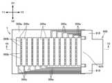
도 1a는 본 발명의 실시예에 관한 터치 패널의 개략적 저면도이다.
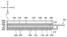
도 1b는 상기 터치 패널의 도 1a 중의 1B-1B 단면도이다.
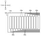
도 2a는 상기 터치 패널의 제1전극 및 제1인출선이 배치된 제1투광성 기재의 개략적 저면도이다.
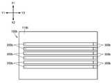
도 2b는 상기 터치 패널의 제2전극 및 제2인출선이 배치된 제2투광성 기재의 개략적 저면도이다.
도 3a는 상기 터치 패널의 제2투광성 기재, 제2전극, 제2인출선, 제2보호층 및 제2저반사 부재의 형성 공정을 나타내는 도면이다.
도 3b는 상기 터치 패널의 제1투광성 기재, 제1전극, 제1인출선, 제1보호층 및 제1저반사 부재의 형성 공정을 나타내는 도면이다.
도 3c는 상기 터치 패널의 제1, 제2적층체의 접합공정 및 FPC 접속공정을 나타내는 도면이다.
도 4는 상기 터치 패널의 제1설계 변경 예를 나타내는 단면도이다.
도 5는 상기 터치 패널의 제2설계 변경 예를 나타내는 단면도이다.1A is a schematic bottom view of a touch panel according to an embodiment of the present invention.
Fig. 1B is a cross-sectional view taken along
2A is a schematic bottom view of a first translucent substrate on which a first electrode and a first lead line of the touch panel are disposed.
2B is a schematic bottom view of a second translucent substrate on which a second electrode and a second lead line of the touch panel are disposed.
3A is a view showing a process of forming the second translucent substrate, the second electrode, the second lead line, the second passivation layer and the second low reflection member of the touch panel.
FIG. 3B is a view showing a process of forming the first transparent base, the first electrode, the first lead line, the first protective layer and the first low reflection member of the touch panel.
3C is a view showing a process of bonding the first and second stacked bodies of the touch panel and an FPC connecting process.
4 is a cross-sectional view showing a first design modification of the touch panel.
5 is a cross-sectional view illustrating a second design modification of the touch panel.
이하, 본 발명의 실시예에 관한 터치 패널에 대하여 도 1a ~ 도 3c를 참조하면서 설명한다. 도 1a 및 도 1b에 나타내는 터치 패널 T는 투영형(投影型) 정전용량방식의 터치 패널이다. 이 터치 패널 T는, 제1, 제2적층체와, FPC((Flexible Printed Circuits)(600)(외부 접속부)와, 투명접착층(700)을 구비하고 있다. 이하, 터치 패널 T의 각 구성 부재에 대하여 상세히 설명한다. 또한, 도 1a ~ 도 2b에 나타내는 X1은 터치 패널 T의 폭방향의 한쪽이며, X2는 터치 패널 T의 폭방향의 다른 한쪽이다. Y1은 터치 패널 T의 길이방향의 한쪽이며, Y2는 터치 패널 T의 길이방향의 다른 한쪽이다. Z1은 터치 패널 T의 두께방향의 한쪽이며, Z2는 터치 패널 T의 두께방향의 다른 한쪽이다. Y1-Y2 방향은, X1-X2 방향과 직교하고 있다. Z1- Z2 방향은, Y1-Y2 방향 및 X1-X2 방향과 직교하고 있다Hereinafter, a touch panel according to an embodiment of the present invention will be described with reference to Figs. 1A to 3C. The touch panel T shown in Figs. 1A and 1B is a projection-type electrostatic capacitive touch panel. The touch panel T includes first and second laminated bodies, an FPC ((Flexible Printed Circuits) 600 (external connection portion), and a transparent
제1적층체는, 제1투광성 기재(100a)와, 복수의 제1전극(200a)과, 복수의 제1인출선(300a)과, 제1보호층(400a)과, 제1저반사 부재(500a)룰 구비하고 있다. 제2적층체는, 제2투광성 기재(100b)와, 복수의 제2전극(200b)과, 복수의 제2인출선(300b)과, 제2보호층(400b)과, 제2저반사 부재(500b)룰 구비하고 있다.The first laminate includes a first
제2투광성 기재(100b)는, 도 1a, 도 1b 및 도 2b에 나타내는 바와 같이, 투명한 유리 시트이다. 제2투광성 기재(100b)의 두께 치수는, 0.05~2.0mm이며, 1.1mm인 것이 보다 바람직하다. 제2투광성 기재(100b)의 두께 치수가 1.1mm인 것이, 제2투광성 기재(100b)의 재료비의 저 코스트와, 제2투광성 기재(100b) 위의 제2전극(200b)의 고감도인 것과의 밸런스가 가장 좋기 때문이다. 제2투광성 기재(100b)는, 제1면(110b)과, 제1면(110b)의 뒤쪽인 제2면(120b)을 가지고 있다. 제2면(120b)은 터치 패널 T의 입력면쪽(앞면쪽(Z1 방향쪽))에 위치하고, 제1면(110b)은 터치 패널 T의 입력면의 반대쪽(뒷면쪽(Z2 방향쪽))에 위치하고 있다. 다시 말하면, 제2면(120b)은, Z1- Z2 방향에 있어서, 제1면(110b) 보다도 후술하는 터치 입력면(520b)의 가까이에 위치하고 있다. 제2면(120b) 위에는, 제1인출선(300a) 및/또는 제2인출선(300b)을 덮도록 가식층(加飾層)을 형성하는 것이 가능하다.The second
제2저반사 부재(500b)는, 도 1b에 나타내는 바와 같이, 안티글레어 처리 및/또는 저반사 처리된 편광판 또는 편광필름이다. 제2저반사 부재(500b)는, 제2투광성 기재(100b)의 제2면(120b) 위에 적층 되어 있다. 제2저반사 부재(500b)는 터치 패널 T의 가장 위층이다. 제2저반사 부재(500b)는, 고착면(510b)과, 고착면(510b)의 뒤쪽인 터치 입력면(520b)을 가지고 있다. 고착면(510b)은, 제2투광성 기재(100b)의 제2면(120b)에 고착되어 있다. 제2저반사 부재(500b)의 고착면(510b)과 제2투광성 기재(100b)의 제2면(120b)과의 사이에는 공기층이 거의 존재하지 않는다. 터치 입력면(520b)은, 손가락이나 터치 펜 등의 검출 대상이 터치 가능한 터치 패널 T의 외부면(가장 윗면)이다. 또한, 제2투광성 기재(100b)가 부서질 경우, 제2저반사 부재(500b)에 의해서 제2투광성 기재(100b)의 비산이 방지될 수 있다.The second
제2전극(200b)은, 도 1a, 도 1b 및 도 2b에 나타내는 바와 같이, Y1-Y2 방향으로 뻗은 기다란 형상의 투명도전막, 도전 와이어 또는 도체이다. 제2전극(200b)은, 제2투광성 기재(100b)의 제1면(110b) 위에 X1-X2 방향으로 간격을 두고 형성되어 있다. 상기 투명도전막은, ITO(산화인듐+산화주석), IZO(산화인듐+산화아연), AZO(알루미늄 도핑된 산화아연) 또는 도전성 고분자(PEDOT 또는 PSS) 등으로 구성되어 있다. 상기 도전 와이어는 은(Ag) 나노 와이어 또는 선 폭 15㎛ 이하의 메탈 와이어 등이다. 상기 도체는, 감광성 은이나 그래프 오프셋 등으로 제작된 선 폭 15㎛ 이하의 금속(예를 들면, Ag, Cu)으로 구성된 도체이다.. As shown in Figs. 1A, 1B, and 2B, the
제2인출선(300b)은, 도 1a, 도 1b 및 도 2b에 나타내는 바와 같이, 기다란 형상의 투명도전막, 금속(예를 들면, 은(Ag), 몰리브덴(Mo), 알루미늄(Al) 또는 구리(Cu)), 합금(예를 들면, 은(Ag), 팔라듐(Pd) 및 구리(Cu)의 합금) 또는 메탈 와이어이다. 상기 투명도전막은 제2전극(200b)의 투명도전막과 같은 소재로 구성하는 것이 가능하다, 제2인출선(300b)은, 제2투광성 기재(100b)의 제1면(110b) 위에 간격을 두고 배치되어 있다. 제2인출선(300b)은, 제1, 제2단부를 가지고 있다, 제2인출선(300b)의 제1단부가 제2전극(200b)의 단부와 접속되어 있다.As shown in Figs. 1A, 1B, and 2B, the
제2전극(200b)이 상기 투명도전막인 경우, 제2투광성 기재(100b)의 제1면(110b) 위에, 투명한 제2인덱스 매칭 층(IMb)(제2굴절률 조정층)이 형성된 구성으로 하는 것이 가능하다. 이 경우, 제2전극(200b) 및 제2인출선(300b)은, 제1면(110b)의 제2인덱스 매칭 층(IMb) 위에 배치되어 있다. 제2인덱스 매칭 층(IMb)은, 제2투광성 기재(100b)와 제2전극(200b)과의 사이에 개재되어 있다. 제2전극(200b)의 상기 투명도전막의 굴절률은 약 1.9~2.0이다. 제2투광성 기재(100b)의 굴절률은 일반적으로 1.4~1.6이다. 제2인덱스 매칭 층(IMb)의 굴절률은, 제2투광성 기재(100b)의 굴절률보다 크고 또한 제2전극(200b)의 상기 투명도전막의 굴절률보다 작다. 제2인덱스 매칭 층(IMb)에 의해, 제2투광성 기재(100b)의 굴절률과 제2전극(200b)의 굴절률과의 차가 좁혀져 있다(즉, 양 굴절률의 차이가 조정되어 있다). 또한, 도 2b ~ 도 3c에서는, 제2인덱스 매칭 층(IMb)은 도시가 생략되어 있다.When the
제2보호층(400b)은, 도 1b에 나타내는 바와 같이, 투명한 아크릴계 수지이다. 제2보호층(400b)은, 제2전극(200b) 및 제2인출선(300b)의 제2단부 이외의 부분을 덮도록 제2투광성 기재(100b)의 제1면(110b) 위에 적층되어 있다. 제2보호층(400b)과 제2투광성 기재(100b)의 제1면(110b)과의 사이에는 공기층이 거의 존재하지 않는다.The second
제1투광성 기재(100a)는, 도 1a ~ 도 2a에 나타내는 바와 같이, 투명한 유리 시트이다. 제1투광성 기재(100a)의 두께 치수는, 0.05~2.0mm이며, 0.55mm인 것이 보다 바람직하다. 제1투광성 기재(100a)의 두께 치수가 0.55mm인 것이, 제1투광성 기재(100a)의 재료비의 저 코스트와, 제1투광성 기재(100a) 위의 제1전극(200a)의 고감도인 것과의 밸런스가 가장 좋기 때문이다. 제1투광성 기재(100a)는, 제1면(110a)과 제1면(110a)의 뒤쪽인 제2면(120a)을 가지고 있다. 제2면(120a)은, 투명접착층(700)에 의해서, 제2보호층(400b)에 고착되어 있다. 제2면(120a)은, 제2투광성 기재(100b)의 제1면(110b)에 대향하고 있다. 제2면(120a)은 터치 패널 T의 입력면쪽(앞면쪽(Z1 방향쪽))에 위치하고, 제1면(110a)은 터치 패널 T의 입력면의 반대쪽(뒷면쪽(Z2 방향쪽))에 위치하고 있다. 다시 말하자면, 제1면(110a)은, Z1-Z2 방향에 있어서 제2면(120a) 보다도 터치 입력면(520b)으로부터 멀리 위치하고 있다.The first
제1전극(200a)은, 도 1a ~ 도 2a에 나타내는 바와 같이, X1-X2 방향으로 뻗은 기다란 형상의 투명도전막, 도전 와이어 또는 도체이다. 제1전극(200a)은, 제1투광성 기재(100a)의 제1면(110a) 위에 Y1-Y2 방향으로 간격을 두고 배설되어 있다. 제1전극(200a)은, 제2전극(200b)에 대해서 평면 위치적으로 대략 직각으로 교차하고 있다. 상기 투명도전막은, ITO(산화인듐+산화주석), IZO(산화인듐+산화아연), AZO(알루미늄 도핑된 산화아연) 또는 도전성 고분자(PEDOT 또는 PSS) 등으로 구성되어 있다. 상기 도전 와이어는 은(Ag) 나노 와이어 또는 선 폭 15㎛ 이하의 메탈 와이어 등이다. 상기 도체는, 감광성 은이나 그래프 오프셋 등으로 제작한 선 폭 15㎛ 이하의 금속(예를 들면, Ag, Cu)으로 구성된 도체이다..As shown in Figs. 1A to 2A, the
또한, 제1, 제2전극 (200a), (200b)의 상기 도전 와이어 및 상기 도체는 투명하지 않다. 그러나, 제1, 제2전극 (200a), (200b)가 상기 도전 와이어 또는 상기 도체인 경우에 있어서도, 제1, 제2전극 (200a), (200b)의 개구율을 80% 이상으로 함으로써(즉, 터치 패널 T의 표시 영역에 있어서의 제1, 제2전극 (200a), (200b)의 점유율을 20% 이하로 함), 상기 제1, 제2전극 (200a), (200b)가 의사적(疑似的)으로 투명하게 된다. Further, the conductive wires and the conductors of the first and
제1인출선(300a)은, 도 1b ~ 도 2a에 나타내는 바와 같이, 기다란 형상의 투명도전막, 금속(예를 들면, 은(Ag), 몰리브덴(Mo), 알루미늄(Al) 또는 구리(Cu)), 합금(예를 들면, 은(Ag), 팔라듐(Pd) 및 구리(Cu)의 합금) 또는 메탈 와이어이다. 상기 투명도전막은 제1전극(200a)의 투명도전막과 같은 소재로 구성하는 것이 가능하다, 제1인출선(300a)은, 제1투광성 기재(100a)의 제1면(110a) 위에 간격을 두고 배치되어 있다. 제1인출선(300a)은, 제1, 제2단부를 가지고 있다. 제1인출선(300a)은, 제1단부가 제1전극(200a)의 X1 방향 및 X2 방향 단부의 어느 한쪽과 접속되며, 제2단부가 제1투광성 기재(100a)의 제1면(110a)인 도 2a에 도시한 오른쪽의 2개의 모서리부의 어느 한쪽에 위치하도록 배선되어 있다.The
제1전극(200a)이 상기 투명도전막일 경우, 제1투광성 기재(100a)의 제1면(110a)의 위에는, 투명한 제1인덱스 매칭 층(IMa)(제1굴절률 조정층)이 형성된 구성으로 하는 것이 가능하다. 이 경우, 제1전극(200a) 및 제1인출선(300a)은, 제1면(110a)의 제1인덱스 매칭 층(IMa) 위에 배치되어 있다. 제1인덱스 매칭 층(IMa)은, 제1투광성 기재(100a)와 제1전극(200a)과의 사이에 개재되어 있다. 제1전극(200a)의 상기 투명도전막의 굴절률은 약 1.9~2.0이다. 제1투광성 기재(100a)의 굴절률은 일반적으로 1.4~1.6이다. 제1인덱스 매칭 층(IMa)의 굴절률은, 제1투광성 기재(100a)의 굴절률보다 크고 또한 제1전극(200a)의 상기 투명도전막의 굴절률보다 작다. 제1인덱스 매칭 층(IMa)에 의해, 제1투광성 기재(100a)의 굴절률과 제1전극(200a)의 굴절률과의 차가 좁혀져 있다(즉, 양 굴절률의 차이가 조정되어 있다). 또한, 도 2a 및 도 3a ~ 도 3c에서는, 제1인덱스 매칭 층(IMa)은 생략되어 있다. When the
제1보호층(400a)은, 도 1b에 나타내는 바와 같이, 투명한 아크릴계 수지이다. 제1보호층(400a)은, 제1전극(200a) 및 제1인출선(300a)의 제2단부 이외의 부분을 덮도록 제1투광성 기재(100a)의 제1면(110a) 위에 적층되어 있다. 제1보호층(400a)과 제1투광성 기재(100a)의 제1면(110a)과의 사이에는 공기층이 거의 존재하지 않는다.The first
제1저반사 부재(500a)는, 도 1a ~도 1b에 나타내는 바와 같이, LR(Low Reflective) 필름이다. 제1저반사 부재(500a)는, 제1전극(200a) 및 제1인출선(300a)의 제2단부 이외의 부분을 덮도록, 제1보호층(400a) 위에 형성되어 있다. 제1저반사 부재(500a)는 터치 패널 T의 가장 아래층이다. 제1전극(200a) 및 제1인출선(300a)은, 제1보호층(400a) 및 제1저반사 부재(500a)에 의해 보호되어 있다. 제1저반사 부재(500a)와 제1보호층(400a)과의 사이에는 공기층이 거의 존재하지 않는다.The first
FPC(600)는, 도 1a 및 도 1b에 나타내는 바와 같이, 한 쌍의 제1접속부(610)와, 제2접속부(620)를 가지고 있다. 제1접속부(610)는, 제2접속부(620)의 양단부로부터 연장 형성되어 있다. 각 제1접속부(610)는, 제1투광성 기재(100a)의 제1면(110a)의 상기 모서리부에 고착되어, 제1인출선(300a)의 상기 제2단부와 접속되어 있다. 제2접속부(620)는, 제2투광성 기재(100b)의 제1면(110b)에 고착되어, 제2인출선(300b)과 접속되어 있다. FPC(600)에 의해서, 터치 패널 T가, 휴대단말 장치나 디스플레이 장치 등의 전자기기와 접속 가능하도록 되어 있다.The
이하, 위에서 설명한 구성인 터치 패널 T의 제조 공정에 대하여 도 3a ~ 도 3c를 참조하면서 설명한다. 또한, 여기서는, 제1, 제2전극 (200a), (200b) 및 제2인출선(300b)은 ITO로 구성되어 있는 것으로 하고, 제1인출선(300a)은 은으로 구성되어 있는 것으로 한다.Hereinafter, the manufacturing process of the touch panel T having the above-described structure will be described with reference to Figs. 3A to 3C. It is assumed here that the first and
아래와 같이, 터치 패널 T의 제2적층체(제2저반사 부재(500b), 제2투광성 기재(100b), 제2전극(200b), 제2인출선(300b) 및 제2보호층(400b))를 형성한다. 먼저, 제2투광성 기재(100b) 및 인덱스 매칭 필름을 준비한다. 그 후, 제2투광성 기재(100b)의 제1면(110b) 위에 도시하지 않은 인덱스 매칭 필름(제2인덱스 매칭 층(IMb))을 접착시킨다. 그러한 후, 제 1면(110b)의 제2인덱스 매칭 층(IMb) 위에 ITO막을 형성한다. 그 후, ITO막을 에칭 등의 주지된 방법으로 패터닝한다. 이로써, 도 3a에 나타내는 바와 같이, 제2투광성 기재(100b)의 제1면(110b)의 제2인덱스 매칭 층(IMb) 위에 복수의 제2전극(200b)이 간격을 두고 형성됨과 동시에, 상기 제1면(110b)의 제2인덱스 매칭 층(IMb) 위에 복수의 제2인출선(300b)이 제2전극(200b)에 연속되도록 형성된다(도 2b 참조).The second laminate (the second
그 후, 제2투광성 기재(100b)의 제1면(110b)의 제2인덱스 매칭 층(IMb) 위에 투명한 아크릴계 수지를 도포한다. 이때, 아크릴계 수지와 제2인덱스 매칭 층(IMb)과의 사이에 공기층이 형성되지 않도록 한다. 상기 아크릴계 수지가 제2보호층(400b)이 된다. 제2보호층(400b)은, 제1면(110b)의 제2인덱스 매칭 층(IMb) 위에 고착되며, 상기 제2인덱스 매칭 층(IMb) 위의 제2전극(200b) 및 제2인출선(300b)의 제2단부 이외의 부분을 덮는다. 그러한 후, 제2투광성 기재(100b)의 제2면(120b)과 제2저반사 부재(500b)의 고착면(510b)과의 사이에 공기층이 형성되지 않도록, 제2투광성 기재(100b)의 제2면(120b)에 제2저반사 부재(500b)의 고착면(510b)을 고착시킨다. 또한, 가식층이 제2투광성 기재(100b)의 제2면(120b) 위에 형성될 경우에는, 제2저반사 부재(500b)를 제2면(120b)에 접착시키기 전에, 상기 제2면(120b) 위에 스크린인쇄나 그라비아인쇄 등을 실시함으로써, 또는, 가식 필름을 첩부함으로써, 가식층을 형성한다.Thereafter, transparent acrylic resin is coated on the second index matching layer IMb of the
그리고 또한, 아래와 같이, 터치 패널 T의 제1적층체(제1투광성 기재(100a), 제1전극(200a), 제1인출선(300a), 제1보호층(400a) 및 제1저반사 부재(500a))를 형성한다. 먼저, 제1투광성 기재(100a) 및 인덱스 매칭 필름을 준비한다. 그 후, 제1투광성 기재(100a)의 제1면(110a) 위에 도시하지 않은 인덱스 매칭 필름(제1인덱스 매칭 층(IMa))을 접착한다. 그러한 후, 제 1면(110a)의 제1인덱스 매칭 층(IMa) 위에 ITO막을 형성한다. 그 후, ITO막을 에칭 등의 주지된 방법으로 패터닝한다. 이로써, 도 3b에 나타내는 바와 같이, 제1투광성 기재(100a)의 제1면(110a)의 제1인덱스 매칭 층(IMa) 위에 복수의 제1전극(200a)이 간격을 두고 형성된다. 그 후, 제1투광성 기재(100a)의 제1면(110a)의 제1인덱스 매칭 층(IMa) 위에 은으로 배선 인쇄를 실시하여, 복수의 제1인출선(300a)을 형성한다. 이때, 제1인출선(300a)의 제1단부가 제1전극(200a)의 X1 방향 및 X2 방향의 단부의 어느 한쪽 위로 중첩되도록 인쇄된다. 이로써 제1인출선(300a)이 제1전극(200a)과 접속된다.The first laminate (the first
그 후, 제1투광성 기재(100a)의 제1면(110a)의 제1인덱스 매칭 층(IMa) 위에 투명한 아크릴계 수지를 도포한다. 이때, 아크릴계 수지와 제1인덱스 매칭 층(IMa)과의 사이에 공기층이 형성되지 않도록 한다. 상기 아크릴계 수지가 제1보호층(400a)이 된다. 제1보호층(400a)이, 제1면(110a)의 제1인덱스 매칭 층(IMa) 위에 고착되며, 상기 제1인덱스 매칭 층(IMa) 위의 제1전극(200a) 및 제1인출선(300a)의 제2단부 이외의 부분을 덮는다. 그러한 후, 제1보호층(400a)과 제1저반사 부재(500a)와의 사이에 공기층이 형성되지 않도록, 제1보호층(400a)에 제1저반사 부재(500a)를 접착시킨다. 이로써, 제1저반사 부재(500a)가 제1면(110a)의 제1인덱스 매칭 층(IMa) 위의 제1전극(200a)을 덮어 보호한다.Thereafter, a transparent acrylic resin is coated on the first index matching layer IMa on the
그 후, 터치 패널 T의 제2적층체와 터치 패널 T의 제1적층체를 접합시킨다. 구체적으로는, 제2보호층(400b) 및/또는 제1투광성 기재(100a)의 제2면(120a) 위에 접착제(투명접착층(700))를 도포한다. 그러한 후, 제2보호층(400b)과 제1투광성 기재(100a)의 제2면(120a)을 투명접착층(700)으로 접착시킨다. 이로써, 터치 패널 T의 제2적층체와 터치 패널 T의 제1적층체가 접합되며, 제2전극(200b)이 제1전극(200a)에 대해서 평면 위치적으로 대략 직각으로 교차한다.Thereafter, the second laminate of the touch panel T and the first laminate of the touch panel T are bonded. Specifically, an adhesive (a transparent adhesive layer 700) is applied on the second
그 후, FPC(600)를 준비한다. 그러한 후, FPC(600)의 제1접속부(610)를 제1투광성 기재(100a)의 제1면(110a) 위에 이방성도전막을 이용하여 압착한다. 이로써, 제1접속부(610)가 제1인출선(300a)과 접속된다. 마찬가지로, FPC(600)의 제2접속부(620)를 제2투광성 기재(100b)의 제1면(110b) 위에 이방성도전막을 이용하여 압착한다. 이로써, 제2접속부(620)가 제2인출선(300b)과 접속된다.Thereafter, the
이상과 같은 터치 패널 T는, 이하의 기술적 특징을 가진다. 첫째, 제1, 제2전극 (200a), (200b)가 터치 패널 T의 제조 공정 및 터치 패널 T의 반송 시에 있어서 손상되는 것을 방지할 수 있다. 구체적으로는, 제1적층체의 형성 공정에 있어서, 제1면(110a) 위에 제1전극(200a)이 형성된 후, 제1면(110a) 위에 제1전극(200a)을 덮도록 제1보호층(400a)이 형성되며, 제1보호층(400a) 위에 제1전극(200a)을 덮도록 제1저반사 부재가 고착된다. 이와 같이, 제1전극(200a)은 제1보호층(400a) 및 제1저반사 부재에 덮이므로, 제1전극(200a)은, 터치 패널 T의 제조 공정 및 그 후에 있어서 손상되지 않는다. 또 제2적층체의 형성 공정에 있어서, 제1면(110b) 위에 제2전극(200b)이 형성된 후, 제1면(110b) 위에 제2전극(200b)을 덮도록 제2보호층(400b)이 형성된다. 이와 같이, 제2전극(200b)은 제2보호층(400b)에 덮이므로, 제2전극(200b)은 터치 패널 T의 제조 공정 및 그 후에 있어서 손상되지 않는다.The touch panel T as described above has the following technical characteristics. First, it is possible to prevent the first and
둘째, 터치 패널 T의 시인성이 향상된다. 그 이유는, 아래와 같다. 제1전극(200a)의 아래에 상기 제1전극(200a)과 굴절률이 크게 상이한 다른 층(제1전극이 노출되어 있는 경우, 상기 다른 층은 공기층(굴절률은 1))이 존재할 경우, 제1전극과 다른 층의 경계면에서 빛이 반사한다. 그러나, 터치 패널 T는, 제1전극(200a)이 제1보호층(400a) 및 제1저반사 부재(500a)에 의해서 덮여 있다. 제1보호층(400a) 및 제1저반사 부재(500a)의 굴절률은 제1전극(200a)의 굴절률에 가깝기 때문에, 제1전극(200a)과 제1보호층(400a) 및 제1저반사 부재(500a)와의 경계면에서 빛이 반사하는 것을 억제할 수 있다. 특히, 제1전극(200a)이 제1저반사 부재(500a)에 의해 덮임으로써, 빛의 반사가 호적하게 억제된다. 또한, 제1인덱스 매칭 층(IMa)이, 제1투광성 기재(100a)와 제1전극(200a)과의 사이에 개재되어 있는 경우, 제1인덱스 매칭 층(IMa)에 의해, 제1투광성 기재(100a))의 굴절률과 제1전극(200a)의 굴절률과의 차가 좁혀진다. 따라서, 제1투광성 기재(100a)와 제1전극(200a)과의 경계면에서 빛이 반사하는 것을 억제할 수 있다. 제2인덱스 매칭 층(IMb)이, 제2투광성 기재(100b)와 제2전극(200b)과의 사이에 개재되어 있는 경우, 제2인덱스 매칭 층(IMb)에 의해, 제2투광성 기재(100b))의 굴절률과 제2전극(200b)의 굴절률과의 차가 좁혀진다. 따라서, 제2투광성 기재(100b)와 제2전극(200b)과의 경계면에서 빛이 반사하는 것을 억제할 수 있다. 또, 제2저반사 부재(500b)에 의해서 빛의 반사가 억제된다.Second, the visibility of the touch panel T is improved. The reason is as follows. When another layer (the first electrode is exposed and the other layer is an air layer (refractive index is 1)) is present under the
셋째, 제1저반사 부재(500a)는, 빛의 반사를 억제함과 동시에, 제1전극(200a)을 보호하고 있으며, 제2저반사 부재(500b)는, 빛의 반사를 억제함과 동시에, 제2투광성 기재(100b)가 부서질 때의 비산을 방지할 수 있다. 즉, 제1, 제2저반사 부재 (500a), (500b)는 두 가지의 기능을 가지고 있으므로, 터치 패널 T는, 상기 제1, 제2저반사 부재 (500a), (500b)를 구비함으로써, 제조 비용이 상승되는 것을 억제할 수 있다.Third, the first
넷째, 터치 패널 T의 저 코스트화 및 감도 향상을 도모할 수 있다. 왜냐하면, 제1, 제2투광성 기재 (100a), (100b)의 두께 치수가 0.05~2.0mm이기 때문에, 제1, 제2투광성 기재 (100a), (100b)의 재료비 저감을 꾀할 수 있음과 동시에, 제1, 제2전극 (200a), (200b)의 감도를 향상시킬 수 있기 때문이다.Fourth, the touch panel T can be reduced in cost and sensitivity can be improved. This is because the thickness dimension of the first and second
또한, 위에서 설명한 터치 패널 T는, 상기 실시예에 한정되는 것이 아니며, 특허 청구의 범위에 기재된 범위에서, 임의로 설계 변경하는 것이 가능하다. 이하, 상세히 설명한다.Further, the touch panel T described above is not limited to the above-described embodiment, and it is possible to arbitrarily change the design in the range described in the claims. Hereinafter, this will be described in detail.
상기 실시예에서는, 제2전극(200b)은, 제1전극(200a)에 대해서 평면 위치적으로 직각으로 교차하도록 제2투광성 기재(100b)의 제1면(110b) 위에 간격을 두고 배치되어 있다고 하였다. 그러나, 본 발명의 제2전극은, 제1전극에 대해서 평면 위치적으로 교차하도록 배치되어 있는 한, 임의로 설정하는 것이 가능하다. 예를 들면, 도 4에 나타내는 터치 패널 T'와 같이, 제2전극(200b')이 제1투광성 기재(100a)의 제2면(120a) 위에 X1-X2 방향으로 간격을 두고 배설되고 또한 Y1-Y2 방향으로 뻗은 구성으로 설계 변경하는 것이 가능하다. 이 제2전극(200b')도 제1전극(200a)에 대해서 대략 직각으로 교차하고 있다. 제2인출선(300b')도 제1투광성 기재(100a)의 제2면(120a) 위에 배설되어 있다. 제2보호층(400b')은, 제2전극(200b') 및 제2인출선(300b')의 제2단부 이외의 부분을 덮도록 제1투광성 기재(100a)의 제2면(120a) 위에 배치되어 있다. 제2저반사 부재(500b')는, 제2보호층 위에 적층 되어 있다. 또한, 제1투광성 기재(100a)의 제1면(110a) 위에 제1인덱스 매칭 층(IMa)이, 제1투광성 기재(100a)의 제2면(120a) 위에 제2인덱스 매칭 층(IMb')이 형성된 구성으로 하는 것이 가능하다. 제1인덱스 매칭 층(IMa) 위에 제1전극(200a)이, 제2인덱스 매칭 층(IMb') 위에 제2전극(200b)이 배치된 구성으로 하는 것이 가능하다.In the above embodiment, the
또한, 도 5에 나타내는 터치 패널 T''와 같이, 제1투광성 기재(100a)의 제1면(110a) 위에 제1전극(200a)을 덮도록 절연막(800)이 형성된 경우, 제2전극(200b'')은, 절연막(800) 위에 X1-X2 방향으로 간격을 두어 배치되고 또한 Y1-Y2 방향으로 뻗은 구성으로 설계 변경하는 것이 가능하다. 이 제2전극(200b'')은, 제1전극(200a)에 대해서 대략 직각으로 교차하고 있다. 제2인출선(300b'')은, 제1투광성 기재(100a)의 제1면(110a) 위에 간격을 두고 배치되어 있다. 제2인출선(300b'')은, 제1, 제2단부를 가지고 있다. 제2인출선(300b'')은, 제1단부가 제2전극(200b'')의 Y2 방향의 단부와 접속되며, 제2단부가 제1투광성 기재(100a)의 제1면(110a)의 도 2a에 도시한 오른쪽 단부에 위치하도록 배선되어 있다. 제1인출선(300a)은, 도 5에서 도시되어 있지 않지만, 상기 실시예와 마찬가지로, 제1투광성 기재(100a)의 제1면(110a)에 배치되어 있다. 제1보호층(400a')은, 제1, 제2전극 (200a), (200b'') 및 제1, 제2인출선 (300a), (300b'')의 제2단부 이외의 부분을 덮도록 절연막(800) 및 제1투광성 기재(100a)의 제1면(110a) 위에 형성되어 있다. 제1저반사 부재(500a')는 제1, 제2전극 (200a), (200b'') 및 제1, 제2인출선 (300a), (300b'')의 제2단부 이외의 부분을 덮도록 제1보호층(400a') 위에 배치되어 있다. 제2저반사 부재(500b'')는 제1투광성 기재(100a)의 제2면(120a) 위에 적층되어 있다. FPC(600')는, 제1투광성 기재(100a)의 제1면(110a)에 고착되며, 제1, 제2인출선 (300a), (300b'')의 제2단부와 접속되어 있다. 또한, 제1투광성 기재(100a)의 제1면(110a) 위에 제1인덱스 매칭 층(IMa)이 형성된 구성으로 하는 것이 가능하다. 제1면(110a)의 제1인덱스 매칭 층(IMa) 위에 제1전극(200a)이 배치된 구성으로 하는 것이 가능하다.When the insulating film 800 is formed to cover the
상기 실시예 및 상기 설계 변형 예에서는, 제1투광성 기재(100a)는, 제1, 제2면 (110a), (120a)를 가지는 투명한 유리 시트라고 하였다. 그러나. 본 발명의 제1투광성 기재는, 터치 패널의 입력면의 반대쪽(뒷면쪽)에 위치하는 제1면과, 상기 터치 패널의 입력면쪽(앞면쪽)에 위치하는 제2면을 가지고 또한 투광성을 가진 부재인 한, 임의로 설계 변경하는 것이 가능하다. 예를 들면, 제1투광성 기재는 투광성을 가진 PET 등의 수지 필름으로 설계 변경하는 것이 가능하다. 또, 제1투광성 기재는, 투광성을 가진 견고한 유리 또는 수지 필름으로 구성하는 것이 가능하며, 투광성을 가진 플랙시블한 유리 또는 수지 필름으로 구성할 수 있다. 제1투광성 기재는, 위에서 설명한 견고한 또는 플랙시블한 유리로 구성되어 있는 경우도, 상기 제1투광성 기재의 두께 치수를 상기 실시예와 같은 두께 치수로 하는 것이 가능하다.In the embodiment and the design modification, the first
본 발명의 제1전극은, 위에서 설명한 제1투광성 기재의 제1면 위에 간격을 두고 배치되어 있는 한, 임의로 설계변경하는 것이 가능하다. 본 발명의 제1전극은, 제1투광성 기재의 제1면 위에 직접 형성된 구성이어도 되고, 제1투광성 기재의 제1면의 인덱스 매칭 층 등의 위에 형성된 구성이어도 된다.The first electrode of the present invention can be arbitrarily changed in design as long as it is disposed on the first surface of the above-described first light-transmitting substrate at intervals. The first electrode of the present invention may be formed directly on the first surface of the first translucent substrate or may be formed on the index matching layer or the like of the first surface of the first translucent substrate.
본 발명의 제1저반사 부재는, 빛의 반사를 저감시킬 수 있는 것으로서, 위에서 설명한 제1전극을 덮는 한, 임의로 설계 변경하는 것이 가능하다. 예를 들면, 터치 패널 T 및 T'에 있어서, 제1저반사 부재(500a)가, 제1전극(200a)을 덮도록, 제1투광성 기재(100a)의 제1면(110a)에 배치된 구성으로 하는 것이 가능하다. 이 경우, 제1보호층(400a)은 생략된다. 터치 패널 T''에 있어서, 제1저반사 부재(500a')가, 제1, 제2전극 (200a), (200b'')를 덮도록, 절연막 위에 형성된 구성으로 하는 것이 가능하다. 이 경우, 제1보호층(400a')은 생략된다. 또, 본 발명의 제1저반사 부재는, 터치 패널의 가장 아래층으로 한정되지 않는다. 즉, 본 발명의 터치 패널은, 제1저반사 부재의 아래쪽에 보호층 등의 별도의 층을 형성하는 것이 가능하다. 또, 위에서 설명한 제1저반사 부재로서 안티글레어 처리 및/또는 저반사 처리가 실시된 편광판 또는 편광 필름을 이용하는 것이 가능하다.The first low reflection member of the present invention is capable of reducing reflection of light and can be arbitrarily changed in design as long as it covers the first electrode described above. For example, in the touch panels T and T ', the first
본 발명에 있어서, 제2투광성 기재는 생략 가능하다(예를 들면, 터치 패널 T 및 T''). 또, 본 발명의 제2투광성 기재는, 제1면 및 상기 제1면의 뒤쪽인 제2면을 가지며, 또한, 투광성을 가진 부재로서, 상기 제1면이 제1투광성 기재의 제2면에 대향하도록 배치되는 한, 임의로 설계 변경하는 것이 가능하다. 예를 들면, 제2투광성 기재는, 투광성을 가진 PET 등의 수지 필름으로 설계 변경하는 것이 가능하다. 또, 제2투광성 기재는, 투광성을 가진 견고한 유리 또는 수지 필름으로 구성하는 것이 가능하며, 투광성을 가진 플랙시블한 유리 또는 수지 필름으로 구성할 수 있다. 제2투광성 기재는, 위에서 설명한 견고한 또는 플랙시블한 유리로 구성되어 있는 경우도, 상기 제2투광성 기재의 두께 치수를 상기 실시예와 같은 두께 치수로 하는 것이 가능하다.In the present invention, the second translucent substrate may be omitted (for example, touch panels T and T ''). The second translucent substrate of the present invention is a member having a first surface and a second surface that is a back side of the first surface and is also a translucent member and the first surface is a It is possible to arbitrarily change the design as long as it is arranged so as to oppose. For example, the second translucent substrate can be changed to a resin film such as PET having translucency. The second translucent substrate can be composed of a rigid glass or resin film having translucency and can be composed of a flexible glass or resin film having translucency. The thickness of the second translucent substrate may be the same as that of the above embodiment even when the second translucent substrate is made of the rigid or flexible glass described above.
본 발명에 있어서, 제2저반사 부재(500b)는 생략 가능하다. 또, 위에서 설명한 제2저반사 부재를 대신하여, 제2투광성 기재의 제2면 또는 제1투광성 기재의 제2면 위에 보호층을 형성하는 것이 가능하다. 또, 위에서 설명한 제2저반사 부재는 터치 패널의 가장 위층으로 한정되지 않는다. 즉, 본 발명의 터치 패널은, 제2저반사 부재의 위쪽에 보호층 또는 화장 패널 등의 별도 층을 형성하는 것이 가능하다. 본 발명의 터치 입력면은, 터치 패널의 가장 윗면 또는 당해 터치 패널이 구비되는 전자기기의 터치 입력부의 외부 면인 한, 임의로 설계 변경하는 것이 가능하다. 또, 본 발명의 제2저반사 부재는, 빛의 반사를 저감시킬 수 있는 한, 어떠한 것을 이용하여도 무방하다. 예를 들면, 위에서 설명한 제2저반사 부재로서 LR 필름을 이용하는 것이 가능하다.In the present invention, the second
본 발명에 있어서, 제1인덱스 매칭 층 및/또는 제2인덱스 매칭 층은 생략 가능하다. 또, 제1인덱스 매칭 층은, 제1전극이 상기 투명도전막 이외의 소재로 구성되어 있는 경우에도, 제1투광성 기재의 제1면 위에 형성하는 것이 가능하다. 이 제1인덱스 매칭 층은, 제1투광성 기재의 굴절률보다 크고 또한 제1전극의 굴절률보다도 작은 굴절률을 가진 소재로 구성되어 있으면 된다. 제1인덱스 매칭 층이 제1투광성 기재의 제1면 위에 형성된 경우에 있어서도, 제1인출선은, 제1투광성 기재의 제1면 위에 형성된 구성으로 하는 것이 가능하다. 제2인덱스 매칭 층은, 제2전극이 상기 투명도전막 이외의 소재로 구성되어 있는 경우에도, 제2투광성 기재의 제1면 또는 제1투광성 기재의 제2면 위에 형성된 구성으로 하는 것이 가능하다. 이 제2인덱스 매칭 층은, 제1투광성 기재 또는 제1투광성 기재의 굴절률보다 크고 또한 제2전극의 굴절률보다 작은 굴절률을 가진 소재로 구성되어 있으면 된다. 제2인덱스 매칭 층이 제2투광성 기재의 제1면 또는 제1투광성 기재의 제2면 위에 형성된 경우에 있어서도, 제2인출선은 제2투광성 기재의 제1면 또는 제1투광성 기재의 제2면 위에 형성된 구성으로 하는 것이 가능하다.In the present invention, the first index matching layer and / or the second index matching layer may be omitted. The first index matching layer can be formed on the first surface of the first translucent substrate even when the first electrode is made of a material other than the transparent conductive film. The first index matching layer may be made of a material having a refractive index that is larger than the refractive index of the first translucent substrate and smaller than the refractive index of the first electrode. Even when the first index matching layer is formed on the first surface of the first translucent substrate, the first lead line can be formed on the first surface of the first translucent substrate. The second index matching layer can be formed on the first surface of the second translucent substrate or on the second surface of the first translucent substrate, even when the second electrode is made of a material other than the transparent conductive film. The second index matching layer may be composed of a material having a refractive index greater than that of the first light-transmitting base material or the first light-transmitting base material and smaller than that of the second electrode. Even in the case where the second index matching layer is formed on the first surface of the second translucent substrate or the second surface of the first translucent substrate, the second lead line may be formed on the first surface of the second translucent substrate or on the second surface of the first translucent substrate It is possible to have a configuration formed on the surface.
본 발명에 있어서, 제1보호층 및/또는 제2보호층은 생략 가능하다. 제1보호층이 생략될 경우, 위에서 설명한 제1저반사 부재는 적어도 제1전극을 덮도록 위에 설명한 제1투광성 기재의 제1면 위에 형성된 구성으로 설계 변경하는 것이 가능하다. 제2보호층이 생략될 경우, 위에서 설명한 제1투광성 기재의 제2면은, 위에 설명한 제2투광성 기재의 제1면 또는 제2저반사 부재에 고착되도록 설계 변경하는 것이 가능하다.In the present invention, the first protective layer and / or the second protective layer may be omitted. When the first protective layer is omitted, the first low reflection member described above can be designed to have a configuration formed on the first surface of the first transparent substrate described above so as to cover at least the first electrode. When the second protective layer is omitted, it is possible to change the design so that the second surface of the first transparent substrate described above is fixed to the first surface of the second transparent substrate or the second low reflective member described above.
본 발명의 제1보호층은, 제1전극 및 제1인출선 중의 적어도 한쪽을 덮는 투광성을 가진 부재인 한, 임의로 설계 변경하는 것이 가능하다. 예를 들면, 터치 패널 T 및 T'에 있어서, 제1보호층(400a)은, 제1전극(200a)의 일부, 제1전극(200a)의 전부 또는 제1인출선(300a)의 제2단부 이외의 부분을 덮는 것과 같은 형상으로 설계 변경하는 것이 가능하다. 제1저반사 부재(500a)는, 제1전극(200a)를 덮도록, 제1보호층(400a) 위 및 제1투광성 기재(100a)의 제1면(110a) 위에 배치되어 있다. 터치 패널 T''에 있어서, 제1보호층(400a')은, 제1, 제2전극 (200a), (200b'')의 일부, 제1, 제2전극 (200a), (200b'')의 전부 또는 제1, 제2인출선 (300a), (300b'')의 제2단부 이외의 부분을 덮는 것과 같은 형상으로 설계 변경하는 것이 가능하다. 제1저반사 부재(500a')는, 제1, 제2전극 (200a), (200b'')를 덮도록, 제1보호층(400a) 위 및 절연막(800) 위에 배치되어 있다.The first protective layer of the present invention can be arbitrarily changed in design as long as it has a light transmitting property covering at least one of the first electrode and the first lead wire. For example, in the touch panels T and T ', the
본 발명의 제2보호층은, 제2전극 및 제2인출선 중의 적어도 한쪽을 덮는 투광성을 가진 부재인 한, 임의로 설계 변경하는 것이 가능하다. 예를 들면, 터치 패널 T에 있어서, 제2보호층(400b)은, 제2전극(200b)의 일부, 제2전극(200b)의 전부 또는 제2인출선(300b)의 제2단부 이외의 부분을 덮는 것과 같은 형상으로 설계 변경하는 것이 가능하다. 제1투광성 기재(100a)의 제2면(120a)은, 제2보호층(400b) 및 제2투광성 기재(100b)의 제1면(110b) 위에 고착된다. 터치 패널 T'에 있어서, 제2보호층(400b')은, 제2전극(200b')의 일부, 제2전극(200b')의 전부 또는 제2인출선(300b')의 제2단부 이외의 부분을 덮는 것과 같은 형상으로 설계 변경하는 것이 가능하다. 제2저반사 부재(500b')는, 제2보호층(400b') 및 제1투광성 기재(100a)의 제2면(120a)에 고착된다.The second protective layer of the present invention can be arbitrarily changed in design as long as it has a light-transmitting property covering at least one of the second electrode and the second lead-out wire. For example, in the touch panel T, the
상기 실시예 및 상기 설계 변경 예에서는, 외부 접속부가 FPC라고 하였다. 그러나, 본 발명의 외부 접속부는, 제1, 제2전극을 외부와 접속 가능한 것인 한,임의로 설계 변경하는 것이 가능하다. 예를 들면, 외부 접속부는, 제1, 제2전극에 접속된 핀 또는 커넥터 등으로 설계 변경하는 것이 가능하다. 또한, 위에서 설명한 제1, 제2인출선의 일부를 외부 접속부로서 사용하는 것도 가능하다.In the above-described embodiment and the design modification example, the external connection portion is an FPC. However, the external connection portion of the present invention can be arbitrarily changed in design as long as the first and second electrodes can be connected to the outside. For example, the external connection portion can be designed and changed to a pin or a connector connected to the first and second electrodes. It is also possible to use a part of the first and second lead wires described above as an external connection portion.
본 발명의 터치 패널의 제조 방법은, 제1투광성 기재를 준비하고, 상기 제1투광성 기재의 제1면 위에 복수의 제1전극을 형성하고, 상기 제1투광성 기재의 상기 제1면 위에 상기 제1전극을 덮도록 제1저반사 부재를 고착시키는 한편, 제2투광성 기재를 준비하고, 상기 제2투광성 기재의 제1면 위에 복수의 제2전극을 형성하고, 상기 제2투광성 기재의 상기 제1면 위에 상기 제2전극을 덮도록 보호층(제2보호층)을 형성하고, 그 후, 상기 제1투광성 기재의 상기 제1면의 뒤쪽인 제2면과 상기 보호층을 접착시킬 수 있는 한, 임의로 설계 변경하는 것이 가능하다. 상기 제1투광성 기재의 제1면 위에 상기 제1전극을 형성하기 전에, 상기 제1투광성 기재의 제1면 위에 제1인덱스 매칭 층을 형성하고, 그 후, 상기 제1전극을 상기 제1인덱스 매칭 층 위에 형성하는 것이 가능하다. 상기 제2투광성 기재의 상기 제1면 위에 상기 제2전극을 형성하기 전에, 상기 제2투광성 기재의 제1면 위에 제2인덱스 매칭 층을 형성하고, 그 후, 상기 제2전극을 상기 제2인덱스 매칭 층 위에 형성하는 것이 가능하다. 상기 제1저반사 부재를 적층하기 전에, 상기 제1투광성 기재의 제1면 위에 상기 제1전극을 덮도록 제1보호층을 형성하고, 상기 제1보호층 위에 제1저반사 부재를 고착시키는 것이 가능하다. 또한, 상기 제2투광성 기재의 상기 제1면의 뒤쪽인 제2면에 제2저반사 부재를 고착시키는 것이 가능하다A manufacturing method of a touch panel of the present invention is a method of manufacturing a touch panel, comprising the steps of: preparing a first light transmitting substrate; forming a plurality of first electrodes on a first surface of the first light transmitting substrate; The first low reflection member is fixed so as to cover one electrode, and a second light-transmitting substrate is prepared, a plurality of second electrodes are formed on the first surface of the second light-transmitting substrate, (Second protective layer) is formed on one surface of the first transparent substrate so as to cover the second electrode, and then the second surface of the first transparent substrate on the rear side of the first transparent substrate is adhered to the protective layer It is possible to arbitrarily design change. Forming a first index matching layer on the first surface of the first translucent substrate before forming the first electrode on the first surface of the first translucent substrate, It can be formed on the matching layer. Forming a second index matching layer on the first surface of the second translucent substrate before forming the second electrode on the first surface of the second translucent substrate, It is possible to form on the index matching layer. A first protective layer is formed on the first surface of the first translucent substrate so as to cover the first electrode and a first low reflective member is fixed on the first protective layer before the first low reflective member is laminated It is possible. It is also possible to fix the second low reflection member on the second surface of the second translucent substrate which is on the rear side of the first surface
또한, 위에서 설명한 터치 패널의 각 구성 부재를 구성하는 소재, 형상, 치수, 숫자 및 배치 등은 그 일례를 설명한 것으로서, 이와 같은 기능을 실현할 수 있는 한, 임의로 설계 변경하는 것이 가능하다. 위에서 설명한 실시예 및 설계 변경 예는, 서로 모순되지 않는 한, 상호 조합시키는 것이 가능하다.The materials, shapes, dimensions, numbers, arrangements, etc. constituting each constituent member of the above-described touch panel are described by way of example. As long as such functions can be realized, it is possible to arbitrarily change the design. The embodiments and the design modifications described above can be combined with each other, unless they are contradictory to each other.
100a: 제1투광성 기재
110a: 제1면
120a: 제2면
100b: 제2투광성 기재
110b: 제1면
120b: 제2면
200a: 제1전극
200b: 제2전극
300a: 제1인출선
300b: 제2인출선
400a: 제1보호층
400b: 제2보호층
500a: 제1저반사 부재
500b: 제2저반사 부재
600: FPC(외부 접속부)
700: 접착층
IMa: 제1인덱스 매칭 층
IMb: 제2인덱스 매칭 층100a: First light-transmitting substrate
110a: first side
120a: second side
100b: second translucent substrate
110b: first side
120b: second side
200a: first electrode
200b: second electrode
300a: first outgoing line
300b: second outgoing line
400a: first protective layer
400b: second protective layer
500a: a first low reflection member
500b: a second low reflection member
600: FPC (external connection part)
700: adhesive layer
IMa: first index matching layer
IMb: second index matching layer
Claims (12)
Translated fromKorean당해 터치 패널 입력면의 반대쪽에 위치하는 제1면 및 당해 터치 패널의 입력면쪽에 위치하는 제2면을 가진 제1투광성 기재와,
상기 제1투광성 기재의 상기 제1면 위에 간격을 두고 배치된 복수의 제1전극과,
상기 제1전극을 덮는 제1저반사 부재를 구비한 터치 패널.In the touch panel,
A first translucent substrate having a first surface located on the opposite side of the touch panel input surface and a second surface located on the input surface side of the touch panel,
A plurality of first electrodes arranged on the first surface of the first translucent substrate with an interval therebetween,
And a first low reflective member covering the first electrode.
상기 제1투광성 기재의 제2면 위에 배치된 제1면 및 상기 제1면의 뒤쪽인 제2면을 가진 제2투광성 기재와,
상기 제1전극에 대해서 평면 위치적으로 교차하도록, 상기 제2투광성 기재의 상기 제1면 위에 간격을 두고 배치된 복수의 제2전극과,
상기 제2투광성 기재의 상기 제2면 위에 형성된 제2저반사 부재를 부가하여 구비한 터치 패널.The method according to claim 1,
A second translucent substrate having a first surface disposed on a second surface of the first translucent substrate and a second surface opposed to the first surface,
A plurality of second electrodes spaced apart from each other on the first surface of the second translucent substrate so as to intersect with the first electrode in a planar positional relationship,
And a second low reflection member formed on the second surface of the second translucent substrate.
상기 제1투광성 기재의 상기 제1면 위에 간격을 두고 배치되고 또한 상기 제1전극과 접속된 복수의 제1인출선과,
상기 제1전극 및 상기 제1인출선 중의 적어도 한쪽을 덮는 제1보호층과,
상기 제2투광성 기재의 상기 제1면 위에 간격을 두고 배치되고 또한 상기 제2전극과 접속된 복수의 제2인출선과,
상기 제2전극 및 상기 제2인출선 중의 적어도 한쪽을 덮는 제2보호층을 부가하여 구비하고 있으며,
상기 제1투광성 기재의 제2면은, 상기 제2투광성 기재의 상기 제1면 및 상기 제2보호층 중의 적어도 한쪽에 고착되어 있으며,
상기 제1저반사 부재는, 상기 제1전극을 덮도록, 상기 제1투광성 기재의 상기 제1면 위 및 상기 제1보호층 위 중의 적어도 한쪽에 형성되어 있는 터치 패널.3. The method of claim 2,
A plurality of first lead lines disposed on the first surface of the first translucent substrate at intervals and connected to the first electrode,
A first protective layer covering at least one of the first electrode and the first lead line,
A plurality of second lead lines disposed on the first surface of the second translucent substrate at intervals and connected to the second electrode,
And a second protective layer covering at least one of the second electrode and the second lead line,
The second surface of the first translucent substrate is fixed to at least one of the first surface of the second translucent substrate and the second protective layer,
Wherein the first low reflection member is formed on at least one of the first surface of the first translucent substrate and the first protective layer so as to cover the first electrode.
상기 제1투광성 기재의 상기 제1면 위에 형성되어 있으며, 또한, 적어도 상기 제1투광성 기재와 상기 제1전극과의 사이에 개재된 제1인덱스 매칭 층과,
상기 제2투광성 기재의 상기 제1면 위에 형성되어 있으며, 또한, 적어도 상기 제2투광성 기재와 상기 제2전극과의 사이에 개재된 제2인덱스 매칭 층을 부가하여 구비하고 있으며,
상기 제1보호층은, 상기 제1전극 및 상기 제1인출선 중의 적어도 한쪽을 덮도록, 상기 제1투광성 기재의 상기 제1면 위 및 상기 제1인덱스 매칭 층 위 중의 적어도 한쪽에 형성되어 있으며,
상기 제2보호층은, 상기 제2전극 및 상기 제2인출선 중의 적어도 한쪽을 덮도록, 상기 제2투광성 기재의 상기 제1면 위 및 상기 제2인덱스 매칭 층 위 중의 적어도 한쪽에 형성되어 있는 터치 패널.The method of claim 3,
A first index matching layer formed on the first surface of the first translucent substrate and interposed between the first translucent substrate and the first electrode,
And a second index matching layer formed on the first surface of the second translucent substrate and interposed between the second translucent substrate and the second electrode,
The first protective layer is formed on at least one of the first surface of the first translucent substrate and the first index matching layer so as to cover at least one of the first electrode and the first lead line ,
The second protective layer is formed on at least one of the first surface of the second translucent substrate and the second index matching layer so as to cover at least one of the second electrode and the second lead line Touch panel.
상기 제1전극에 대해서 평면 위치적으로 교차하도록, 상기 제1투광성 기재의 상기 제2면 위에 간격을 두고 배치된 복수의 제2전극과,
상기 제2전극을 덮는 제2저반사 부재를 부가하여 구비한 터치 패널.The method according to claim 1,
A plurality of second electrodes spaced apart from each other on the second surface of the first translucent substrate so as to intersect with the first electrode in a planar positional relationship,
And a second low reflective member covering the second electrode.
상기 제1투광성 기재의 상기 제1면 위에 간격을 두고 배치되고 또한 상기 제1전극과 접속된 복수의 제1인출선과,
상기 제1전극 및 상기 제1인출선 중의 적어도 한쪽을 덮는 제1보호층과,
상기 제1투광성 기재의 상기 제2면 위에 간격을 두고 배치되고 또한 상기 제2전극과 접속된 복수의 제2인출선과,
상기 제2전극 및 상기 제2인출선 중의 적어도 한쪽을 덮는 제2보호층을 부가하여 구비하고 있으며,
상기 제1저반사 부재는, 상기 제1전극을 덮도록, 상기 제1투광성 기재의 상기 제1면 위 및 상기 제1보호층 위 중의 적어도 한쪽에 형성되어 있으며,
상기 제2저반사 부재는, 상기 제2전극을 덮도록, 상기 제1투광성 기재의 상기 제2면 위 및 상기 제2보호층 위 중의 적어도 한쪽에 형성되어 있는 터치 패널.6. The method of claim 5,
A plurality of first lead lines disposed on the first surface of the first translucent substrate at intervals and connected to the first electrode,
A first protective layer covering at least one of the first electrode and the first lead line,
A plurality of second lead lines disposed on the second surface of the first translucent substrate at intervals and connected to the second electrode,
And a second protective layer covering at least one of the second electrode and the second lead line,
The first low reflection member is formed on at least one of the first surface of the first translucent substrate and the first protective layer so as to cover the first electrode,
And the second low reflection member is formed on at least one of the second surface of the first translucent substrate and the second protective layer so as to cover the second electrode.
상기 제1투광성 기재의 상기 제1면 위에 형성되어 있으며, 또한, 적어도 상기 제1투광성 기재와 상기 제1전극과의 사이에 개재된 제1인덱스 매칭 층과,
상기 제1투광성 기재의 상기 제2면 위에 형성되어 있으며, 또한, 적어도 상기 제1투광성 기재와 상기 제2전극과의 사이에 개재된 제2인덱스 매칭 층을 부가하여 구비하고 있으며,
상기 제1보호층은, 상기 제1전극 및 상기 제1인출선 중의 적어도 한쪽을 덮도록, 상기 제1투광성 기재의 상기 제1면 위 및 상기 제1인덱스 매칭 층 위 중의 적어도 한쪽에 형성되어 있으며,
상기 제2보호층은, 상기 제2전극 및 상기 제2인출선 중의 적어도 한쪽을 덮도록, 상기 제1투광성 기재의 상기 제2면 위 및 상기 제2인덱스 매칭 층 위 중의 적어도 한쪽에 형성되어 있는 터치 패널.The method according to claim 6,
A first index matching layer formed on the first surface of the first translucent substrate and interposed between the first translucent substrate and the first electrode,
And a second index matching layer formed on the second surface of the first translucent substrate and interposed between the first translucent substrate and the second electrode,
The first protective layer is formed on at least one of the first surface of the first translucent substrate and the first index matching layer so as to cover at least one of the first electrode and the first lead line ,
The second protective layer is formed on at least one of the second surface of the first translucent substrate and the second index matching layer so as to cover at least one of the second electrode and the second lead line Touch panel.
상기 제1전극을 덮도록, 상기 제1투광성 기재의 상기 제1면 위에 형성된 절연막과,
상기 제1전극에 대해서 평면 위치적으로 교차하도록, 상기 절연막 위에 간격을 두고 배치된 복수의 제2전극과,
상기 제1투광성 기재의 상기 제2면 위에 배치된 제2저반사 부재를 부가하여 구비하고 있으며,
상기 제1저반사 부재가 상기 제1, 제2전극을 덮고 있는 터치 패널.The method according to claim 1,
An insulating film formed on the first surface of the first translucent substrate so as to cover the first electrode,
A plurality of second electrodes spaced apart from each other on the insulating film so as to intersect with the first electrode in plan view,
And a second low reflection member disposed on the second surface of the first translucent substrate,
Wherein the first low reflection member covers the first and second electrodes.
상기 제1투광성 기재의 상기 제1면 위에 간격을 두고 배치되고 또한 상기 제1전극과 접속된 복수의 제1인출선과,
상기 제1투광성 기재의 상기 제1면 위에 간격을 두고 배치되고 또한 상기 제2전극과 접속된 복수의 제2인출선과,
상기 제1, 제2전극 또는 상기 제1, 제2인출선을 덮는 제1보호층을 부가하여 구비하고 있으며,
상기 제1저반사 부재는, 상기 제1, 제2전극을 덮도록, 상기 절역막 위 및 상기 제1보호층 위 중의 적어도 한쪽에 형성되어 있는 터치 패널.9. The method of claim 8,
A plurality of first lead lines disposed on the first surface of the first translucent substrate at intervals and connected to the first electrode,
A plurality of second lead lines disposed on the first surface of the first translucent substrate with an interval therebetween and connected to the second electrode,
And a first protective layer covering the first and second electrodes or the first and second lead lines,
Wherein the first low reflection member is formed on at least one of the top protective film and the first protective film so as to cover the first and second electrodes.
상기 제1투광성 기재의 상기 제1면 위에 형성되어 있으며, 또한, 적어도, 상기 제1투광성 기재와 상기 제1전극과의 사이에 개재된 제1인덱스 매칭 층을 부가하여 구비하고 있는 터치 패널.10. The method of claim 9,
And a first index matching layer formed on the first surface of the first translucent substrate and interposed between the first translucent substrate and the first electrode.
상기 제1투광성 기재는 유리로 구성되어 있으며, 상기 제1투광성 기재의 두께 치수가, 0.05~2.0mm인 터치 패널.9. The method according to any one of claims 1 to 8,
Wherein the first translucent substrate is made of glass and the thickness dimension of the first translucent substrate is 0.05 to 2.0 mm.
상기 제2투광성 기재는 유리로 구성되어 있으며, 상기 제2투광성 기재의 두께 치수가, 0.05~2.0mm인 터치 패널.5. The method according to any one of claims 2 to 4,
Wherein the second translucent substrate is made of glass and the thickness dimension of the second translucent substrate is 0.05 to 2.0 mm.
Applications Claiming Priority (4)
| Application Number | Priority Date | Filing Date | Title |
|---|---|---|---|
| JPJP-P-2013-036812 | 2013-02-27 | ||
| JP2013036812 | 2013-02-27 | ||
| JPJP-P-2013-255699 | 2013-12-11 | ||
| JP2013255699AJP2014194749A (en) | 2013-02-27 | 2013-12-11 | Touch panel |
Publications (1)
| Publication Number | Publication Date |
|---|---|
| KR20140107113Atrue KR20140107113A (en) | 2014-09-04 |
Family
ID=50272538
Family Applications (1)
| Application Number | Title | Priority Date | Filing Date |
|---|---|---|---|
| KR1020140004915AWithdrawnKR20140107113A (en) | 2013-02-27 | 2014-01-15 | Touch panel |
Country Status (6)
| Country | Link |
|---|---|
| US (1) | US20140240619A1 (en) |
| EP (1) | EP2772839A2 (en) |
| JP (1) | JP2014194749A (en) |
| KR (1) | KR20140107113A (en) |
| CN (1) | CN104007872A (en) |
| TW (1) | TW201441892A (en) |
Cited By (1)
| Publication number | Priority date | Publication date | Assignee | Title |
|---|---|---|---|---|
| US10318026B2 (en) | 2014-12-09 | 2019-06-11 | Lg Innotek Co., Ltd. | Touch window |
Families Citing this family (8)
| Publication number | Priority date | Publication date | Assignee | Title |
|---|---|---|---|---|
| CN103490648B (en)* | 2013-10-10 | 2015-12-09 | 成都芯源系统有限公司 | Isolated switch converter and control method thereof |
| US9541965B1 (en)* | 2014-03-10 | 2017-01-10 | Amazon Technologies, Inc. | Cover assembly for a display stack |
| CN104699309B (en)* | 2015-03-31 | 2017-06-13 | 合肥京东方光电科技有限公司 | A kind of touch-screen, its preparation method and display device |
| JP6052330B2 (en)* | 2015-04-24 | 2016-12-27 | Tdk株式会社 | Transparent conductor, manufacturing method thereof, and touch panel |
| CN105260050A (en)* | 2015-09-10 | 2016-01-20 | 昆山龙腾光电有限公司 | Embedded touch control display device |
| CN105138191B (en)* | 2015-10-15 | 2019-02-26 | 京东方科技集团股份有限公司 | A touch display device and its manufacturing method |
| JP6814106B2 (en)* | 2017-08-01 | 2021-01-13 | ホシデン株式会社 | Touch input device |
| US10923002B1 (en)* | 2019-08-29 | 2021-02-16 | Wuhan China Star Optoelectronics Semiconductor Display Technology Co., Ltd. | Flexible display device |
Family Cites Families (13)
| Publication number | Priority date | Publication date | Assignee | Title |
|---|---|---|---|---|
| JP3779515B2 (en)* | 1999-11-10 | 2006-05-31 | グンゼ株式会社 | Touch panel |
| JP4632589B2 (en)* | 2001-08-06 | 2011-02-16 | 大日本印刷株式会社 | Transparent touch panel with antireflection function and display device using the same |
| JP5413937B2 (en)* | 2006-09-28 | 2014-02-12 | 株式会社ジャパンディスプレイ | Electro-optical device and electronic apparatus |
| US20090096763A1 (en)* | 2007-10-16 | 2009-04-16 | Epson Imaging Devices Corporation | Touch panel, display device with input function, and electronic apparatus |
| CN101498972B (en)* | 2008-02-01 | 2012-07-18 | 台达电子工业股份有限公司 | touch panel |
| JP2009259063A (en) | 2008-04-18 | 2009-11-05 | Gunze Ltd | Touch panel and its production method |
| JP4958020B2 (en)* | 2009-03-31 | 2012-06-20 | 大日本印刷株式会社 | Touch panel sensor, laminate for manufacturing touch panel sensor, and method for manufacturing touch panel sensor |
| US20110012841A1 (en)* | 2009-07-20 | 2011-01-20 | Teh-Zheng Lin | Transparent touch panel capable of being arranged before display of electronic device |
| US20110012845A1 (en)* | 2009-07-20 | 2011-01-20 | Rothkopf Fletcher R | Touch sensor structures for displays |
| KR101122949B1 (en)* | 2010-04-28 | 2012-06-12 | 삼성모바일디스플레이주식회사 | Touch screen panel and fabricating method for the same |
| JP2012138019A (en)* | 2010-12-27 | 2012-07-19 | Dainippon Printing Co Ltd | Display device with touch panel |
| KR101294569B1 (en)* | 2011-06-29 | 2013-08-07 | 엘지이노텍 주식회사 | Touch panel and method for manufacturing the same |
| US9079384B2 (en)* | 2011-11-11 | 2015-07-14 | Apple Inc. | Touch sensor panel having an index matching passivation layer |
- 2013
- 2013-12-11JPJP2013255699Apatent/JP2014194749A/enactivePending
- 2014
- 2014-01-09TWTW103100816Apatent/TW201441892A/enunknown
- 2014-01-15KRKR1020140004915Apatent/KR20140107113A/ennot_activeWithdrawn
- 2014-02-12EPEP14250024.8Apatent/EP2772839A2/ennot_activeWithdrawn
- 2014-02-24USUS14/187,790patent/US20140240619A1/ennot_activeAbandoned
- 2014-02-25CNCN201410063463.2Apatent/CN104007872A/enactivePending
Cited By (1)
| Publication number | Priority date | Publication date | Assignee | Title |
|---|---|---|---|---|
| US10318026B2 (en) | 2014-12-09 | 2019-06-11 | Lg Innotek Co., Ltd. | Touch window |
Also Published As
| Publication number | Publication date |
|---|---|
| JP2014194749A (en) | 2014-10-09 |
| EP2772839A2 (en) | 2014-09-03 |
| US20140240619A1 (en) | 2014-08-28 |
| TW201441892A (en) | 2014-11-01 |
| CN104007872A (en) | 2014-08-27 |
Similar Documents
| Publication | Publication Date | Title |
|---|---|---|
| KR20140107113A (en) | Touch panel | |
| EP2746907B1 (en) | Touch display device and method of manufacturing the same | |
| US11061504B2 (en) | Input sensing unit and display device including the same | |
| US20160147325A1 (en) | Fan-out trace structure of touch module of touch device | |
| US10705640B2 (en) | Touch panel and method for fabricating the same, touch display device | |
| TW201510805A (en) | Touch device | |
| US20110315536A1 (en) | Touch panel | |
| KR20120067031A (en) | Flat panel display device integrated with touch screen | |
| CN201622557U (en) | Improved touch panel | |
| KR101328867B1 (en) | Transparent adhesive unit and touch screen having the same | |
| WO2015133041A1 (en) | Display panel, display apparatus, and liquid crystal panel manufacturing method | |
| CN108717341A (en) | Capacitive touch display panel, capacitive touch panel and manufacturing method thereof | |
| JP2012118936A (en) | Touch panel sensor with transparent sheet | |
| US9665224B2 (en) | Capacitive touchscreen | |
| KR102105607B1 (en) | Capacitive sensor | |
| JP2008065762A (en) | Touch panel which has high environmental durability, and its manufacturing method | |
| JP2016194748A (en) | Intermediate member for touch panel sensor and electrical inspection method for intermediate member for touch panel sensor | |
| JP5659684B2 (en) | Touch panel substrate and manufacturing method thereof | |
| TW201602854A (en) | Touch panel | |
| TWM484741U (en) | Touch device | |
| JP2012018590A (en) | Input device and electro-optical device using the same | |
| KR20150082803A (en) | Touch panel and manufacturing method thereof | |
| JP6384177B2 (en) | Touch panel sensor, touch panel device, and display device | |
| JP2016194746A (en) | Intermediate member for touch panel sensor and method for manufacturing touch panel sensor | |
| CN222192960U (en) | Display device |
Legal Events
| Date | Code | Title | Description |
|---|---|---|---|
| PA0109 | Patent application | Patent event code:PA01091R01D Comment text:Patent Application Patent event date:20140115 | |
| PG1501 | Laying open of application | ||
| PC1203 | Withdrawal of no request for examination | ||
| WITN | Application deemed withdrawn, e.g. because no request for examination was filed or no examination fee was paid |