KR20140104388A - Multi-purpose interface for a portable electronic device - Google Patents
Multi-purpose interface for a portable electronic deviceDownload PDFInfo
- Publication number
- KR20140104388A KR20140104388AKR1020140019640AKR20140019640AKR20140104388AKR 20140104388 AKR20140104388 AKR 20140104388AKR 1020140019640 AKR1020140019640 AKR 1020140019640AKR 20140019640 AKR20140019640 AKR 20140019640AKR 20140104388 AKR20140104388 AKR 20140104388A
- Authority
- KR
- South Korea
- Prior art keywords
- link
- interface
- band
- portable electronic
- electronic device
- Prior art date
- Legal status (The legal status is an assumption and is not a legal conclusion. Google has not performed a legal analysis and makes no representation as to the accuracy of the status listed.)
- Granted
Links
Images


Classifications
- G—PHYSICS
- G06—COMPUTING OR CALCULATING; COUNTING
- G06F—ELECTRIC DIGITAL DATA PROCESSING
- G06F1/00—Details not covered by groups G06F3/00 - G06F13/00 and G06F21/00
- G06F1/16—Constructional details or arrangements
- G06F1/1613—Constructional details or arrangements for portable computers
- G06F1/163—Wearable computers, e.g. on a belt
Landscapes
- Engineering & Computer Science (AREA)
- Computer Hardware Design (AREA)
- Theoretical Computer Science (AREA)
- Human Computer Interaction (AREA)
- Physics & Mathematics (AREA)
- General Engineering & Computer Science (AREA)
- General Physics & Mathematics (AREA)
- Telephone Set Structure (AREA)
Abstract
Translated fromKoreanDescription
Translated fromKorean본 개시 내용은 발목 또는 손목 주위에 착용하는 밴드에 관한 것이다. 본 개시 내용은 또한 휴대용 전자 장치의 무선 충전 및 휴대용 전자 장치와의 정보 교환을 제공할 수 있는, 원하는 보기 배향으로 휴대용 전자 장치를 지지할 수 있는 휴대용 전자 장치용 스탠드에 관한 것이다. 본 개시 내용은 따라서 휴대용 전자 장치용 다목적 충전 인터페이스에 관한 것이며, 충전 인터페이스는 손목시계 또는 팔찌 또는 발찌로서 사용자에 착용가능하다.The present disclosure relates to bands worn around ankles or wrists. This disclosure also relates to a stand for a portable electronic device capable of supporting the portable electronic device in a desired viewing orientation that can provide wireless charging of the portable electronic device and information exchange with the portable electronic device. The present disclosure thus relates to a multipurpose charging interface for portable electronic devices and the charging interface is wearable to a user as a wristwatch or bracelet or footrest.
휴대용 전자 장치를 비롯한 전자 장치가 널리 사용되어 왔고, 예를 들어, 전화, 전자 메시징 및 기타 PIM(personal information manager) 응용 프로그램 기능을 비롯한 각종의 기능들을 제공할 수 있다. 휴대용 전자 장치는, 예를 들어, 무선 802.11 또는 블루투스 기능을 갖는 간단한 셀룰러폰, 스마트폰, 무선 PDA(personal digital assistant), 태블릿 컴퓨터, 및 랩톱 컴퓨터 등의 몇가지 유형의 이동국을 포함하고 있다.Electronic devices, including portable electronic devices, have been in wide use and can provide a variety of functions including, for example, telephone, electronic messaging, and other personal information manager (PIM) application functions. Portable electronic devices include several types of mobile stations, for example, wireless 802.11 or simple cellular phones with Bluetooth capabilities, smart phones, wireless personal digital assistants (PDAs), tablet computers, and laptop computers.
오늘날의 세계에서, 휴대용 전자 장치를 사용함에 있어서의 사용자의 경험을 향상시키기 위해 다양한 보조 장치가 개발되어 왔다. 예를 들어, 사용자는 휴대용 전자 장치를 재충전시키기 위해 휴대용 충전 장치를 사용할 수 있거나, 그의 휴대용 전자 장치와 관련하여 외부 스피커를 사용할 수 있다. 사용자는 정보를 휴대용 전자 장치로 또는 그로부터 전송하기 위해 외부 인터페이스를 이용할 수 있고, 또한 휴대용 전자 장치로부터 전송되는 정보를 보기 위해 외부 디스플레이를 이용할 수 있다. 스탠드 또는 도킹 스테이션은 휴대용 전자 장치의 배터리를 충전시키기 위해 전원에 결합되어 있는 동안 전자 장치에 대한 편리한 리셉터클(receptacle)을 제공할 수 있다. 이러한 스탠드는 또한 휴대용 전자 장치와, 예를 들어, 컴퓨터 사이의 데이터 전송을 위한 인터페이스를 제공할 수 있다.In today's world, a variety of auxiliary devices have been developed to enhance the user's experience in using portable electronic devices. For example, a user may use a portable charging device to recharge a portable electronic device, or may use an external speaker in connection with his portable electronic device. A user may use an external interface to transfer information to or from the portable electronic device, and may also use an external display to view information transmitted from the portable electronic device. The stand or docking station may provide a convenient receptacle for the electronic device while it is coupled to the power source to charge the battery of the portable electronic device. Such a stand may also provide an interface for data transfer between the portable electronic device and, for example, a computer.
안타깝게도, 이러한 보조 장치의 사용이 요망되는 시간 또는 장소에 그 장치를 신뢰성 있게 운반하거나 찾는 것이 불편할 수 있다.Unfortunately, it may be inconvenient to reliably transport or locate the device at the time or place where the use of such an assist device is desired.
본 개시 내용의 보다 완전한 이해를 위해, 유사한 참조 번호가 유사한 부분을 나타내고 있는, 첨부 도면 및 상세한 설명과 관련하여 기술된 이하의 간략한 설명을 참조한다.
도 1은 휴대용 전자 장치의 한 예의 블록도.
도 2는 휴대용 전자 장치의 한 예의 다른 도면.
도 3은 스탠드 구성(stand configuration)으로 되어 있는 예시적인 다목적 밴드를 나타낸 도면.
도 4는 스탠드 구성으로 되어 있는 예시적인 다목적 밴드를 나타낸 도면.
도 5는 사용자의 손목 또는 발목에 착용하기 위한 밴드 구성(band configuration)으로 배열되어 있는 다목적 밴드를 나타낸 도면.
도 6은 사용자의 손목 또는 발목에 착용하기 위한 밴드 구성으로 배열되어 있는 다목적 밴드를 나타낸 도면.
도 7은 스탠드 구성으로 되어 있는 다목적 밴드를 나타낸 도면.BRIEF DESCRIPTION OF THE DRAWINGS For a more complete understanding of the present disclosure, reference is made to the following brief description, taken in conjunction with the accompanying drawings and detailed description, wherein like reference numerals denote like parts.
1 is a block diagram of an example of a portable electronic device;
2 is another view of one example of a portable electronic device.
Figure 3 shows an exemplary multi-purpose band in a stand configuration.
Figure 4 shows an exemplary multipurpose band with a stand configuration;
Figure 5 shows a multi-purpose band arranged in a band configuration for wear on a user's wrist or ankle;
Figure 6 shows a multi-purpose band arranged in a band configuration for wear on the wrist or ankle of a user.
7 is a view showing a multi-purpose band having a stand configuration;
휴대용 전자 장치와 함께 사용하기 위한 다목적 밴드가 본 명세서에 기술되어 있다. 다목적 밴드는 적어도 2개의 상이한 구성으로 배열되도록 구성되어 있다. 소위 "밴드 구성"으로 되어 있을 때, 다목적 밴드는 사용자의 손목 또는 발목에 착용하도록 구성되어 있다. 소위 "스탠드 구성"("충전 스탠드 구성"이라고도 할 수 있음)으로 되어 있을 때, 다목적 밴드는 지지 각도(support angle)로 휴대용 전자 장치를 지지하도록 구성되어 있다. 이 개시 내용에서, 요소들은 하나 이상의 기능을 수행하도록 "구성되어"(또는 기능들을 위해 "구성되어" 또는 기능들을 수행할 수 있도록 "구성되어") 있는 것으로 기술될 수 있다. 일반적으로, 기능을 수행하도록 구성되어 있는 요소는 기능을 수행하는 데 적당하거나, 기능을 수행하는 데 적합하게 되어 있거나, 기능을 수행하는 동작을 하거나, 다른 방식으로 기능을 수행할 수 있다.Multipurpose bands for use with portable electronic devices are described herein. The multipurpose bands are configured to be arranged in at least two different configurations. When so-called "band configuration ", the multipurpose band is configured to be worn on the user's wrist or ankle. The so-called "stand configuration" (also referred to as a "charging stand configuration") is configured to support the portable electronic device at a support angle. In this disclosure, elements may be described as being "configured" (or "configured" for functions or "configured" to perform functions) to perform one or more functions. In general, an element configured to perform a function may be suitable for performing a function, adapted to perform a function, perform an operation to perform a function, or perform a function in a different manner.
먼저, 비록 본 개시 내용의 하나 이상의 실시예의 예시된 구현이 이하에 제공되어 있지만, 개시된 시스템 및/또는 방법이, 현재 알려져 있는 기법이든 기존의 기법이든, 임의의 수의 기법들을 사용하여 구현될 수 있다는 것을 잘 알 것이다. 본 개시 내용은 본 명세서에 예시되고 기술되어 있는 예시적인 설계 및 구현을 비롯하여 이하에 예시되어 있는 예시적인 구현, 도면 및 기법으로 결코 제한되어서는 안되며, 그의 등가물의 전범위와 함께 첨부된 특허청구범위의 범위 내에서 수정될 수 있다.First, although an exemplary implementation of one or more embodiments of the present disclosure is provided below, it is contemplated that the disclosed system and / or method may be implemented using any number of techniques, whether presently known or existing techniques You know. The present disclosure is not to be limited in any way by the exemplary implementations, drawings and techniques illustrated below, including the exemplary designs and implementations illustrated and described herein, and is intended to cover all modifications of the appended claims Lt; / RTI >
예시의 간단함 및 명확함을 위해, 대응하거나 유사한 요소들을 나타내는 데 도면들 간에 참조 번호가 반복될 수 있다. 본 명세서에 기술된 예들에 대한 이해를 제공하기 위해 수많은 상세가 기술되어 있다. 예들이 이들 상세 없이 실시될 수 있다. 다른 경우에, 기술된 예들을 불명료하게 하는 것을 피하기 위해, 공지된 방법, 절차 및 구성요소가 상세히 기술되어 있지 않다. 이 설명은 본 명세서에 기술된 예들의 범위로 제한되는 것으로 간주되어서는 안된다.BRIEF DESCRIPTION OF THE DRAWINGS For simplicity and clarity of illustration, reference numerals may be repeated among the figures to indicate corresponding or analogous elements. Numerous details are set forth in order to provide an understanding of the examples described herein. Examples can be implemented without these details. In other instances, well-known methods, procedures, and components have not been described in detail in order to avoid obscuring the examples described. This description should not be construed as limiting the scope of the examples described herein.
"실질적인" 또는 "일반적으로"와 같은 단어들은, 본 명세서에서 사용되는 바와 같이, 설명을 위한 것이고 엄격한 적용 또는 엄격한 수학적 정의를 피하기 위한 것이다. 예로서, "실질적으로 평행"인 2개의 표면은 엄격히 평행이거나 대략 평행일 수 있고; "실질적으로 평행사변형"인 형상은 대략 평행사변형일 수 있지만, 정확히 평행사변형이 아닐 수 있고, 예를 들어, 둥근 모서리를 가질 수 있으며; "일반적으로 수직"은 정확히 수직을 포함하지만 그것으로 제한되지 않는다. 그렇지만, (상세한 설명에 그리고 특허청구범위에) 엄격한 적용 또는 정의를 명확히 피하는 어떤 단어도 없음이 엄격함이 의도되어 있음을 꼭 의미하는 것은 아니다.The words "substantial" or "generally" are intended to be illustrative and to avoid strict application or strict mathematical definition, as used herein. By way of example, two surfaces that are "substantially parallel" may be strictly parallel or approximately parallel; A shape that is "substantially parallelogram" may be approximately a parallelogram, but may not be exactly parallelograms, and may have, for example, rounded corners; "Generally vertical" includes but is not limited to exactly vertical. However, nothing in the description (and in the claims) to preclude strict application or definition, does not necessarily mean that strictness is intended.
본 명세서에 기술된 다목적 밴드는 다양한 구성요소들을 포함하는 각종의 휴대용 전자 장치에 이용될 수 있다. 어떤 실시예들에서, 예를 들어, 밴드는 전기 구성요소들 또는 가동 부분들을 포함할 수 있고, 밴드 및/또는 스탠드로서 역할하는 것 이외의 기능들을 수행할 수 있다. 그렇지만, 다른 실시예들에서, 밴드는 스탠드로서 역할하지 않을 수 있고(즉, 그것은 휴대용 전자 장치를 지지하는 역할을 하지 않을 수 있고), 그 대신에, 휴대용 전자 장치용 밴드로서 또는 휴대용 전자 장치용 스탠드로서 사용하는 것에 꼭 관련되어 있지는 않은 역할을 할 수 있다.The multipurpose band described herein can be used in a variety of portable electronic devices including various components. In some embodiments, for example, the band may comprise electrical components or moving parts and may perform functions other than serving as a band and / or a stand. However, in other embodiments, the band may not serve as a stand (i.e., it may not serve to support a portable electronic device), and instead may be used as a band for a portable electronic device, It can play a role not necessarily related to the use as a stand.
앞서 간략히 언급한 바와 같이, 단점들이 휴대용 전자 장치와 함께 사용하기 위한 보조 장치의 확산과 연관되어 있을 수 있다. 예를 들어, 보조 구성요소 또는 장치를 찾아 기능 어셈블리 내에 연결하는 것이 번거롭고 불편할 수 있다. 한 위치에서 다른 위치로 이동할 때, 구성요소들을 잘못 두었을 수 있거나, 접근가능하지 않은 위치에 보관하였을 수 있거나(예컨대, 탁송 수하물), 단순히 잊어버리거나 잊고 가버릴 수 있다. 어떤 경우에, 다수의 기능들(예컨대, 카메라 및 셀폰)을 단일의 패키지 내에 통합시키는 것이 바람직할 수 있다. 그렇지만, 실용적인 이유(예컨대, 중량 및 크기)로, 모든 보조 장치들(예컨대, 충전 스탠드, 원격 디스플레이, 보조 전력 저장 장치, 정보 중계 스테이션)을 휴대용 전자 장치 내에 통합시키는 것이 바람직하지 않을 수 있다.As mentioned briefly above, disadvantages may be associated with the spread of ancillary equipment for use with portable electronic devices. For example, finding and connecting auxiliary components or devices within functional assemblies can be cumbersome and inconvenient. When moving from one location to another, components may be misplaced, stored in inaccessible locations (eg, checked baggage), or simply forgotten or forgotten. In some cases, it may be desirable to integrate multiple functions (e.g., camera and cell phone) into a single package. However, for practical reasons (e.g., weight and size) it may not be desirable to integrate all the auxiliary devices (e.g., charging stand, remote display, auxiliary power storage, information relay station) into the portable electronic device.
스마트 전화(스마트폰) 및 태블릿 컴퓨터 등의 어떤 휴대용 전자 장치들은 사용 편의성 및 휴대성을 위해 핸드헬드일 수 있다. 즉, 핸드헬드 장치는 사람의 손에 보유 또는 소지되도록 하는 크기 및 형상으로 되어 있고, 보유되어 있는 동안 사용될 수 있다. 많은 휴대용 전자 장치는 장치의 배향을 검출하고 대응하는 배향으로 정보를 디스플레이하기 위해 가속도계 등의 배향 감지 장치를 포함하고 있다. 휴대용 전자 장치는 통상적으로 장치 상에서 실행 중인 응용 프로그램에 의존하는 배향으로 사용된다. 게다가, 개개의 사용자는 한 목적을 위해서는 한 배향으로 그리고 다른 목적을 위해서는 다른 배향으로 휴대용 전자 장치를 사용하는 것을 선호할 수 있다. 휴대용 전자 장치를 상이한 배향으로 이동시키는 것을 용이하게 해주는 스탠드는, 충전 동안 및/또는 데이터 전송 동안, 사용자에게 디스플레이하는 것을 용이하게 하기 위해 휴대용 전자 장치의 사용 편의성를 향상시키는 데 바람직하다.Some portable electronic devices, such as smart phones (smart phones) and tablet computers, may be handheld for ease of use and portability. That is, the handheld device is sized and shaped to be held or carried by a person's hand, and can be used while held. Many portable electronic devices include an orientation sensing device, such as an accelerometer, to detect the orientation of the device and display information in a corresponding orientation. Portable electronic devices are typically used in an orientation that depends on the application running on the device. In addition, individual users may prefer to use portable electronic devices in one orientation for one purpose and in a different orientation for another purpose. A stand that facilitates moving the portable electronic device in different orientations is desirable to improve the usability of the portable electronic device to facilitate display to the user during charging and / or during data transfer.
휴대용 전자 장치(100)의 한 예의 블록도가 도 1에 도시되어 있다. 휴대용 전자 장치(100)는 휴대용 전자 장치(100)의 전체적인 동작을 제어하는 프로세서(102) 등의 다수의 구성요소들을 포함하고 있다. 휴대용 전자 장치(100)의 예는 페이저, 셀룰러폰, 셀룰러 스마트폰, 무선 오거나이저(wireless organizer), PDA(personal digital assistant), 무선 지원 노트북 컴퓨터, 태블릿 컴퓨터, 모바일 인터넷 장치, 전자 내비게이션 장치, 또는 휴대용 스피커 등의 모바일 또는 핸드헬드 무선 통신 장치를 포함한다. 휴대용 전자 장치(100)는 또한 핸드헬드 전자 게임, 디지털 사진 앨범, 디지털 카메라, 미디어 플레이어, 또는 e-북 리더(e-book reader) 등의 무선 통신 기능을 갖지 않는 장치일 수 있다.A block diagram of one example of a portable
데이터 및 음성 통신을 비롯한 통신 기능은, 휴대용 전자 장치(100)와 무선으로 통신하도록 구성되어 있을 수 있고 무선 송신기 및 수신기를 포함할 수 있는 통신 서브시스템(104)을 통해 수행된다. 휴대용 전자 장치(100)에 의해 수신되는 데이터는 디코더(106)에 의해 압축 해제되고 복호화된다. 통신 서브시스템(104)은 무선 네트워크(150)로부터 메시지를 수신하고, 무선 네트워크(150)로 메시지를 송신한다. 무선 네트워크(150)는 데이터 무선 네트워크, 음성 무선 네트워크, 및 음성 및 데이터 통신 둘 다를 지원하는 네트워크(이들로 제한되지 않음)를 비롯한 임의의 유형의 무선 네트워크일 수 있다. 하나 이상의 재충전가능 배터리 등의 휴대용 전자 장치(100)에 대한 전원으로서 기능하는 전력 저장 구성요소(142)는 휴대용 전자 장치(100)에 전원을 공급한다. 휴대용 전자 장치(100)는 또한 전력 저장 구성요소(142)가 무선으로 또는 물리적 전기 연결을 통해 또는 둘 다에 의해 재충전될 수 있게 해줄 수 있는 유도 코일 및 전력 제어기 등의 충전 회로(도시 생략)를 포함할 수 있다. 이하에서 논의될 것인 바와 같이, 밴드의 일부 실시예들은 휴대용 전자 장치(100)에 전력을 전달하는 데 또는 휴대용 전자 장치(100) 내의 배터리를 재충전시키는 데 사용될 수 있다.Communication functions, including data and voice communications, are performed through the
프로세서(102)는 RAM(Random Access Memory)(108), 메모리(110), 터치 감응 디스플레이(118), 하나 이상의 작동기(actuator), 하나 이상의 힘 센서, 보조 입/출력(I/O) 서브시스템(124), 데이터 포트(126), 스피커(128), 마이크(130), 단거리 통신(132), 및 기타 장치 서브시스템(134) 등의 다른 구성요소들과 상호작용한다. 터치 감응 디스플레이(118)는 디스플레이(112) 및 프로세서(102)와 상호작용하는 데 이용되는 적어도 하나의 제어기(116)에 결합되어 있는 하나 이상의 터치 센서를 포함하는 오버레이(114)를 포함하고 있다. 그래픽 사용자 인터페이스를 통한 입력은 통상적으로 터치 감응 디스플레이(118)를 통해 제공된다. 휴대용 전자 장치(100) 상에 디스플레이되거나 렌더링될 수 있는 텍스트, 문자, 심볼, 영상, 아이콘, 및 기타 아이템 등의 정보가 프로세서(102)를 통해 터치 감응 디스플레이(118) 상에 디스플레이된다. 프로세서(102)는 또한 중력 또는 중력-유발 반작용력의 방향을 검출하는 데 이용될 수 있는 가속도계(136) 등의 배향 센서와 상호작용할 수 있다.The
네트워크 액세스에 대해 가입자를 식별하기 위해, 휴대용 전자 장치(100)는 무선 네트워크(150) 등의 네트워크와 통신하기 위해 SIM/RUIM(Subscriber Identity Module/Removable User Identity Module) 카드(138)를 이용할 수 있다. 다른 대안으로서, 사용자 식별 정보가 메모리(110) 내에 프로그램될 수 있다.To identify a subscriber for network access, the portable
휴대용 전자 장치(100)는 프로세서(102)에 의해 실행되고 통상적으로 메모리(110) 등의 영속적 업데이트 가능 저장소에 저장되어 있는 운영 체제(146) 및 소프트웨어 프로그램, 응용 프로그램, 또는 구성요소(148)를 포함하고 있다. 부가의 응용 프로그램 또는 프로그램이 무선 네트워크(150), 보조 I/O 서브시스템(124), 데이터 포트(126), 단거리 통신(132), 또는 임의의 다른 장치 서브시스템(134)을 통해 휴대용 전자 장치(100)에 로드될 수 있다.The portable
문자 메시지, 이메일 메시지, 또는 웹 페이지 다운로드 등의 수신 신호가 통신 서브시스템(104)에 의해 처리되고 프로세서(102)에 입력된다. 프로세서(102)는 디스플레이(112)로 및/또는 보조 I/O 서브시스템(124)으로 출력하기 위해 수신 신호를 처리한다. 가입자는 통신 서브시스템(104)을 통해 무선 네트워크(150)를 거쳐 전송될 수 있는 데이터 항목(예를 들어, 이메일 메시지)을 발생할 수 있다. 음성 통신에 대해서도, 휴대용 전자 장치(100)의 전체적인 동작은 유사하다. 스피커(128)는 전기 신호로부터 변환되는 가청 정보를 출력하고, 마이크(130)는 처리를 위해 가청 정보를 전기 신호로 변환한다.Received signals, such as text messages, email messages, or web page downloads, are processed by the
터치 감응 디스플레이(118)는 오버레이(114)가 포함하고 있는 하나 이상의 용량성 터치 센서를 포함하는 용량성 터치 감응 디스플레이일 수 있다. 용량성 터치 센서는 ITO(indium tin oxide) 등의 임의의 적당한 물질을 포함할 수 있다.The touch sensitive display 118 may be a capacitive touch sensitive display including one or more capacitive touch sensors that the overlay 114 contains. The capacitive touch sensor may comprise any suitable material, such as indium tin oxide (ITO).
터치 접촉 또는 터치 이벤트라고도 하는 하나 이상의 터치가 터치 감응 디스플레이(118)에 의해 검출될 수 있다. 프로세서(102)는 터치의 위치를 비롯한 터치의 속성을 확인할 수 있다. 터치 위치 데이터는 접촉 영역에 대한 데이터 또는 단일의 접촉점(접촉 영역의 중앙에 또는 그 근방에 있는 지점 등)에 대한 데이터를 포함할 수 있다. 검출된 터치의 위치는 터치 감응 디스플레이(118)의 뷰에 대한 x 및 y 성분(예컨대, 각각, 수평 및 수직 성분)을 포함할 수 있다. 터치 감응 디스플레이(118)의 특성에 따라, 손가락, 엄지손가락, 부속물, 또는 기타 물체(예를 들어, 스타일러스, 펜, 또는 기타 포인터) 등의 임의의 적당한 입력 부재로부터 터치가 검출될 수 있다. 다수의 동시적인 터치가 검출될 수도 있다.One or more touches, also referred to as touch contacts or touch events, may be detected by the touch sensitive display 118. The
이제 도 2를 참조하면, 휴대용 전자 장치(100)는 배면(160) 상에 배치되어 있는 및/또는 배면(160) 내에 함몰되어 있는 하나 이상의 특징부를 포함할 수 있는 배면(160)을 포함하고 있다. 이러한 특징부는 디지털 카메라 장치(162) 및 그래픽 요소(164)[휴대용 전자 장치(100)와 연관되어 있는 로고, 등록 상표 또는 임의의 텍스트, 심볼 또는 이들의 조합을 포함할 수 있음]를 포함할 수 있다. 배면(160) 상에 배치되어 있는 또는 배면(160) 내에 함몰되어 있는 특징부에 관계없이, 적어도 하나의(통상적으로 복수의) 전기 커넥터(166)가 배면(160)에 근접하여 통합되어 있다. 배면(160)의 다른 특징부에서와 같이, 전기 커넥터(166)가 돌출부의 형태로 배면(160)으로부터 바깥쪽으로 연장해 있는 것이 생각되고 있다.Referring now to Figure 2, the portable
다른 대안으로서, 하나 이상의 전기 커넥터(166)가 배면(160) 내에 함몰된 영역으로서 통합되어 있을 수 있다. 또한, 복수의 전기 커넥터(166)가 돌출부와 함몰부의 조합을 포함하는 것이 생각되고 있다. 또 다른 실시예에서, 복수의 전기 커넥터(166)는 배면(160)과 동일 높이의 전체 표면을 형성할 수 있다. 게다가, 복수의 전기 커넥터(166)가 비교적 수직으로 정렬된 배열 등의 수많은 정렬로 배열되어 있을 수 있지만, 복수의 전기 커넥터(166)가 비교적 수평인 배열, 각진 배열, 비선형 배열 및/또는 군집된 배열로 정렬될 수 있다는 것을 잘 알 것이다. 상기 배열들의 목록은 예시적인 실시예들을 나타낸 것에 불과하고, 복수의 전기 커넥터(166)의 특정의 배열을 제한하기 위한 것이 아니다.As another alternative, one or more
복수의 전기 커넥터(166) 중 적어도 하나는 자성 물질로 형성되어 있다. 복수의 전기 커넥터(166) 각각은, 예시되어 있는 바와 같이, 통상적으로 배면(160)의 외부 위치로부터 보이는 외측 부분(168)을 포함하고 있으며, 여기서 외측 부분(168)은 배면(160)의 외부 위치로부터 접근가능하다. 복수의 전기 커넥터(166) 각각은 또한 휴대용 전자 장치(100)의 내부 구성요소[예를 들어, 전력 저장 구성요소(142) 등]와 통신하는 내측 부분을 포함하고 있다. 복수의 전기 커넥터(166) 각각의 내측 부분과 전력 저장 구성요소(142) 간의 통신은 개별 접점, 선택적 도금, PCB(printed circuit board), 전선 또는 기술 분야에 공지되어 있는 임의의 다른 적당한 통신 방식을 통해 이루어진다.At least one of the plurality of
비록 복수의 전기 커넥터(166)가 배면(160)에 근접한 다양한 위치에 배치될 수 있지만, 도시된 예시적인 실시예에서, 복수의 전기 커넥터(166)가 그래픽 요소(164) 내에 배치되는 것이 생각되고 있다.Although it is contemplated that in the illustrated exemplary embodiment, a plurality of
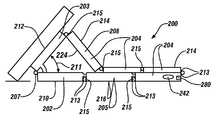
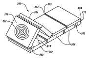
이제 도 3 및 도 4를 참조하면, 다목적 밴드(200)가 스탠드 구성으로 도시되어 있다. 다목적 밴드(200)는 베이스 링크(base link)(202), 인터페이스 링크(interface link)(203), 스태빌라이저 링크(stabilizer link)(205), 및 베이스 링크(202), 인터페이스 링크(203)와 스태빌라이저 링크(205) 사이에 배치되어 있는 하나 이상의 결합 링크(coupling link)(204)를 포함하고 있다. 한 예시적인 실시예에서, 베이스 링크(202)는 인터페이스 지지 힌지(interface support hinge)(207)에 의해 인터페이스 링크(203)에 결속(join)된다. (일반적으로, 구성요소들은, 분리가능하게든 실질적으로 영구적이든 간에, 한쪽 구성요소의 물리적 활동이 일반적으로 다른쪽 구성요소에 영향을 미치도록, 서로 물리적으로 결합될 때 또는 임의의 방식으로 서로 부착 또는 연결될 때 "결속"된다. 문맥에 따라, 구성요소들은 서로 직접 또는 하나 이상의 중간 요소를 통해 결속될 수 있다. 다목적 밴드(200)가 스탠드 구성으로 있을 때, 인터페이스 지지 힌지(207)는 휴대용 전자 장치(100)를 원하는 배향으로 지지하는 것을 용이하게 해주도록 구성되어 있다. 보다 구체적으로는, 인터페이스 지지 힌지(207)는 그 인터페이스 지지 힌지(207)가 베이스 링크(202)와 인터페이스 링크(203) 사이에 지지 각도(211)를 정의하도록 구성되어 있을 수 있다. 이 실시예에 따르면, 인터페이스 지지 힌지(207) 및 베이스 링크(202)의 결합에 의해 인터페이스 링크(203)에 대한 지지, 따라서, 인터페이스 링크(203)가 제공된다.Referring now to Figures 3 and 4, the
앞서 언급한 바와 같이, "~이도록 구성되어" 및 "~하도록 구성되어"라는 문구는 요소 또는 특징부가 지정된 기능을 수행할 수 있는 요소 또는 특징부의 상태를 말한다. 요소 또는 특징부가 항상 지정된 기능을 꼭 수행하는 것은 아닐지라도, 요소는 기능을 수행하도록 구성되어 있을 수 있다. 예를 들어, 인터페이스 지지 힌지(207)에 대한 이상의 설명으로부터, 다목적 밴드(200)가 스탠드 구성으로 되어 있을 때 인터페이스 지지 힌지(207)가 휴대용 전자 장치(100)를 원하는 배향으로 지지하는 것을 용이하게 해줄 수 있다는 것을 잘 알 것이다. 더욱이, 다목적 밴드(200)가 스탠드 구성으로 되어 있을 때 인터페이스 지지 힌지(207)가 휴대용 전자 장치(100)를 원하는 배향으로 지지하는 것을 용이하게 해줄 수 있다 - 인터페이스 지지 힌지(207)가 항상 꼭 그렇게 하는 것은 아닐지라도 - 는 것을 잘 알 것이다.As stated above, the phrase " configured to "and" configured to "refer to a state of an element or feature capable of performing a specified function. An element may be configured to perform a function, even if the element or feature does not always perform the specified function. For example, from the above description of the
대안의 실시예에서, 다목적 밴드(200)가 스탠드 구성으로 되어 있을 때, 결합 링크(204)의 배향에 의해 지지 각도(211)가 정의될 수 있다. 이 실시예에 따르면, 인터페이스 링크(203)는 압축되어 위치해 있는 결합 링크(204)에 의해 지지되고, 결합 링크(204)는 인터페이스 링크(203)에 대해 받침대(kickstand)(208)로서 역할한다. 그에 따라, 이 실시예는 인터페이스 링크(203)가 인터페이스 지지 힌지(207)에 의해 지지되는 것을 필요로 하지 않는다.In an alternative embodiment, when the
도 5 및 도 6에 도시된 바와 같이, 한 예시적인 실시예에서, 다목적 밴드(200)는 또한 사용자의 손목(300)에 착용하기 위해 밴드 구성으로 배열될 수 있다. (도 3 및 도 4에 도시되어 있는 것과 같은) 스탠드 구성으로부터 (도 5 및 도 6에 도시되어 있는 것과 같은) 밴드 구성으로 및/또는 밴드 구성으로부터 스탠드 구성으로의 재배열을 용이하게 해주기 위해, 다목적 밴드(200)의 각각의 링크[즉, 베이스 링크(202), 인터페이스 링크(203), 스태빌라이저 링크(205), 및 하나 이상의 결합 링크 링크(204)]가 힌지 커넥터(hinged connector)(215)에 의해 각자의 에지(213)에서 서로 결속된다. 달리 말하면, 베이스 링크(202), 인터페이스 링크(203), 스태빌라이저 링크(205), 및 결합 링크(204) 각각은 2개의 에지(213)를 정의하며, 각각의 에지는 힌지 커넥터(215)에 의해 다른 베이스 링크(202), 인터페이스 링크(203), 스태빌라이저 링크(205), 또는 결합 링크(204)의 에지(213)에 결속된다. 각각의 힌지 커넥터(215)는 밴드 구성 및 스탠드 구성 둘 다에 부응하기 위해 [베이스 링크(202), 인터페이스 링크(203), 결합 링크(204) 및 스태빌라이저 링크(205)로 이루어져 있는 그룹 중에서 선택되는 하나 이상의 링크로 이루어져 있는] 인접 링크들의 일정 범위의 상대 배향(즉, 그들 사이의 각도)을 용이하게 해주도록 구성되어 있다. 보다 구체적으로는, 도 5에 도시된 실시예에 따르면, 힌지 커넥터(215)는 그의 연관된 링크들[즉, 베이스 링크(202)와 인터페이스 링크(203)] 사이에 약 100도 내지 150도의 각도를 용이하게 해주도록 구성되어 있다. 그 결과, 다목적 밴드(200)는 밴드 구성으로부터 스탠드 구성으로 재배열될 수 있다.As shown in FIGS. 5 and 6, in one exemplary embodiment, the
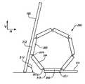
한 예시적인 실시예에서, 도 7에 도시된 바와 같이, 2개 이상의 인터페이스 지지 힌지(207)의 조합에 의해 지지 각도(211)가 정의될 수 있다. 도 7에 도시된 실시예에서, 베이스 링크(202)는 제1 인터페이스 지지 힌지(207a)에 의해 결합 링크(204)에 결속된다. 결합 링크(204)는 제2 인터페이스 지지 힌지(207b)에 의해 인터페이스 링크(203)에 결속된다. 제1 인터페이스 지지 힌지(207a) 및 제2 인터페이스 지지 힌지(207b)는, 함께, 휴대용 전자 장치(100)가 배치되는 지지 각도(211)를 정의한다. 이 실시예에 따르면, 다목적 밴드(200)가 스탠드 구성으로 되어 있을 때, 스태빌라이저(219)가 베이스 링크(202)로부터 베이스 링크(202)에 실질적으로 평행한 방향으로 연장하도록 설치된다. 다목적 밴드(200)가 밴드 구성으로 되어 있을 때, 스태빌라이저(219)는 후퇴되도록(즉, 후퇴된 위치를 차지하도록) 구성되어 있을 수 있다. 예를 들어, 스태빌라이저(219)는 베이스 링크(202)에 정의되어 있는 캐비티(217) 내로 슬라이딩하도록 또는 베이스 링크(202)와 정렬되어 있고 그의 측면을 따라 있는 후퇴된 위치로 회전하도록 구성되어 있을 수 있다.In one exemplary embodiment, a
인터페이스 링크(203)의 원하는 배향이 수직 V로부터 벗어나 있는 지지 각도(211)로 기울어져 있을 수 있다는 것을 잘 알 것이다. 예를 들어, 하나의 바람직한 각도는 수직 V로부터 약 30도이고, 이는 휴대용 전자 장치(100)가 역시 안정된 편리한 시야각으로 지지될 수 있게 해준다. 수직으로부터 약 0도 내지 수평 H로부터 단지 약 15도를 비롯한 다른 배향들이 가능하다. 다른 예시적인 배향은 약 45도이다. 그에 따라, 지지 힌지들(207)에 의해 제공되는 정확한 각도 범위가 달라질 수 있지만, 일반적으로 원하는 지지 각도(211)을 정의하도록 결합된다.It will be appreciated that the desired orientation of the
각각의 링크[즉, 베이스 링크(202), 인터페이스 링크(203), 하나 이상의 결합 링크(204), 및 스태빌라이저 링크(205)]는 외측 표면[본 명세서에서, 각각, 베이스 외측 표면(210), 인터페이스 표면(212), 결합 외측 표면(214), 및 스태빌라이저 외측 표면(216)이라고 함]을 포함하고 있다. 그에 부가하여, 각각의 링크[즉, 베이스 링크(202), 인터페이스 링크(203), 하나 이상의 결합 링크(204), 및 스태빌라이저 링크(205)]는 내측 표면[본 명세서에서, 각각, 베이스 내측 표면(218), 인터페이스 내측 표면(220), 결합 내측 표면(222), 및 스태빌라이저 내측 표면(224)이라고 함]을 포함하고 있다. 또한, 다목적 밴드(200)가 밴드 구성으로 되어 있을 때, 베이스 내측 표면(218), 인터페이스 내측 표면(220), 결합 내측 표면(222) 및 스태빌라이저 내측 표면(224)은 다목적 밴드(200)를 통해 연장해 있는 통로(230)를 정의한다. 통로(230)는 사용자의 손목(300) 또는 발목에 다목적 밴드(200)를 착용하는 것을 용이하게 해주기 위해 사용자의 손 또는 발에 편안하게 들어 맞는 크기로 되어 있다. 그에 따라, 다목적 밴드(200)는 사용자의 손목(300) 또는 발목에 차고 운반될 수 있고, 그로써 충전 스탠드 등의 보조 장치와 함께 이동하는 바람직하지 않은 측면을 감소시킨다.Each of the links (i.e., the
표면들, 특히 베이스 외측 표면(210), 인터페이스 표면(212), 및 스태빌라이저 외측 표면(216)이 비교적 평탄하거나 다양한 정도의 곡률을 포함할 수 있다는 것을 잘 알 것이다. 적어도 하나의 충전 특징부(240)가 인터페이스 표면(212)에 근접하여 인터페이스 링크(203) 상에 배치되어 있다. 충전 특징부가 휴대용 전자 장치(100) 등의 전하 수용 구조물(charge-receiving structure)의 충전(즉, 그로의 에너지 전달)을 용이하게 해주는 동작을 하는 임의의 물리적 구조물일 수 있다는 것을 잘 알 것이다. 충전 특징부(240)와 휴대용 전자 장치(100) 사이의 에너지 전달(즉, 전기 또는 전자기 결합)을 용이하게 해주기 위해, 충전 특징부(240)는 충전 특징부와 휴대용 전자 장치(100)의 짝을 이루는 특징부(mating feature)(전기 커넥터 등) 간의 충전 관계의 설정을 용이하게 해주도록 구성되어 있을 수 있다. 충전 특징부는 전극, 유도 코일, 도체, 전기 커넥터, 전기 전도성 단자, 짝을 이루는 스마트폰 내에 포함되어 있는 유도성 패드(inductive pad)로 전력을 전송하기 위한 무선 전력 전달 코일 등을 포함할 수 있다. 휴대용 전자 장치(100)의 배면(160)의 복수의 전기 커넥터(166)와 유사하게, 복수의 충전 특징부(240)가 돌출부의 형태로 인터페이스 표면(212)으로부터 바깥쪽으로 연장해 있거나 인터페이스 표면(212) 내에 함몰된 영역으로서 통합되어 있는 것이 생각되고 있다. 또한, 복수의 충전 특징부(240)가 돌출부와 함몰부의 조합을 포함하는 것이 생각되고 있다. 게다가, 복수의 충전 특징부(240)는 수많은 정렬로 배열되어 있을 수 있다. 그렇지만, 복수의 충전 특징부(240)가 비교적 각진 배열, 비선형 배열 및/또는 군집된 배열로 정렬될 수 있다는 것을 잘 알 것이다. 상기 배열들의 목록은 예시적인 실시예들을 나타낸 것에 불과하고, 복수의 충전 특징부(240)의 특정의 배열을 제한하기 위한 것이 아니다.It will be appreciated that the surfaces, particularly the base
복수의 충전 특징부(240)의 정확한 구성에 관계없이, 복수의 충전 특징부(240)와 복수의 전기 커넥터(166) 사이에 대응하는 관계가 설정되고, 휴대용 전자 장치(100)와 다목적 밴드(200)의 계합이 용이하게 된다. 휴대용 전자 장치(100)와 다목적 밴드(200) 사이의 적절한 정렬 및 배향을 보장해주기 위해, 복수의 충전 특징부(240) 중 일부분이 자성 물질로 형성되어 있다.A corresponding relationship is established between the plurality of charging features 240 and the plurality of
다목적 밴드(200)와 휴대용 전자 장치(100) 사이의 계합은 복수의 전기 커넥터(166)와 복수의 충전 특징부(240)의 자기 인력에 의해 용이하게 된다. 복수의 전기 커넥터(166) 및 복수의 충전 특징부(240)를 형성하는 자성 물질은, 이하에 기술되는 바와 같이, 사용자가 원하는 정확한 배향(즉, "세로" 또는 "가로")으로 구조적 연결을 유지하면서, 다목적 밴드(200)와 휴대용 전자 장치(100) 사이의 전기적 연결을 용이하게 해준다. 자기 인력의 세기는, 휴대용 전자 장치(100)의 중량 및 기하 형태 등의 인자들을 고려하여, 특정의 용도 적용에 의존한다. 일반적으로, 자기 인력은 휴대용 전자 장치(100)의 중력 중심(center of gravity)에서의 휴대용 전자 장치(100)의 중력보다 더 크고, 그로써 휴대용 전자 장치(100)의 중력 중심을 휴대용 전자 장치(100)의 주변부 내에 유지하는 것을 보장해준다. 휴대용 전자 장치(100)와 다목적 밴드(200) 사이의 자기 부착은 즉각 이용가능한 부착 및 분리 기능을 용이하게 해주고, 이는 유리하게도 짝을 이루는 리셉터클 내에 구성요소를 삽입하는 것과 연관되어 있는 번거로운 절차를 감소시킨다. 이러한 부착은 아주 다양한 휴대용 전자 장치를 계합시키는 데 다목적 밴드(200)의 보다 큰 적응성을 제공한다.The engagement between the
도 3 및 도 7에 도시된 바와 같이, 다목적 밴드(200)는 휴대용 전자 장치(100)와 지지 관계에 있는 것으로 예시되어 있다. 예시된 실시예들에서, 베이스 링크(202)의 베이스 외측 표면(210) 및 스태빌라이저 링크(205)의 스태빌라이저 외측 표면(216)은 실질적으로 평면인 수평 배향된 표면과 접촉하여 그 위에 있는 것으로 도시되어 있다.As shown in FIGS. 3 and 7, the
계합 시에, 다목적 밴드(200)는 휴대용 전자 장치(100)를 바람직한 배향으로 위치시키기 위해 지지를 제공할 수 있다. 그렇지만, 복수의 충전 특징부(240)를 포함하는 예시적인 실시예는 다목적 밴드(200)와 휴대용 전자 장치(100) 사이에 전기적 연결을 제공한다. 본 발명은 다목적 밴드(200)가 충전 소스와 휴대용 전자 장치(100) 사이의 교환가능한 요소로서 기능하는 것을 제공한다. 따라서, 다목적 밴드(200)는, 여전히 충전을 용이하게 해주면서, 휴대용 전자 장치(100)에 구조적 견고성을 제공한다. 다목적 밴드(200)가 전원과 연동(operable communication)하는 경우 또는 밴드 전력 저장 구성요소(242)가 다목적 밴드(200)에 배치되어 있는 경우, 이러한 전기적 연결은 유리하다. 어느 구성이든 휴대용 전자 장치(100)로의, 보다 구체적으로는 그 안에 배치되어 있는 전력 저장 구성요소(142)로의 전력 전달을 제공한다. 복수의 충전 특징부(240)와 복수의 전기 커넥터(166) 사이의 직접적인 물리적 연결이 다목적 밴드(200)로부터 휴대용 전자 장치(100)로의 전력 전달을 용이하게 해줄 수 있다는 것을 잘 알 것이다. 그렇지만, 유도 등의 무선 연결이 적절히 전력을 전력 저장 구성요소(142)로 전달할 수 있는 것이 생각되고 있다.At the time of engagement, the
다목적 밴드(200)는 복수의 배향으로 휴대용 전자 장치(100)를 지지하도록 구성되어 있다. 제1 배향이 예시되어 있고 휴대용 전자 장치(100)의 비교적 수직인 배향에 대응한다. 비교적 수직인 배향은 "세로" 배향이라고 할 수 있다. 앞서 상세히 도시되고 논의된 바와 같이, 인터페이스 표면(212)은 휴대용 전자 장치(100)의 배면(160)과 계합하는 반면, 베이스 링크(202)의 베이스 외측 표면(210)의 적어도 일부분은 수평 표면 상에 있다. 휴대용 전자 장치(100)의 원하는 배향을 제공하기 위해, 인터페이스 링크(203)의 인터페이스 표면(212)은 실질적으로 편평한 표면으로서 형성되어 있다. 스탠드 구성에서, 인터페이스 표면(212)은 휴대용 전자 장치(100)의 각도 배향을 정의하기 위해 수직으로부터 어떤 각도로 배치되어 있다. 이 특징은 원하는 배향을 제공하기 위해 원하는 세로 배향을 달성하도록 각도를 변화시킴으로써 다양한 다른 실시예들의 형태를 취할 수 있다.The multi-purpose band (200) is configured to support the portable electronic device (100) in a plurality of orientations. A first orientation is illustrated and corresponds to a relatively vertical orientation of the portable
휴대용 전자 장치(100)가 실질적으로 수평인 배향("가로" 배향이라고 할 수 있음)으로 배치될 수 있다는 것을 잘 알 것이다. 그에 따라, 휴대용 전자 장치(100)를 세로 배향으로부터 가로 배향으로 재배향시키기 위해 휴대용 전자 장치(100)가 90도 회전될 것이다. 인터페이스 표면(212)의 각도 조절(angling)은 가로 배향으로부터 세로 배향으로의 휴대용 전자 장치(100)의 이러한 재배향 이후에 다목적 밴드(200)가 휴대용 전자 장치(100)의 신뢰할 수 있는 지지를 제공할 수 있게 해준다.It will be appreciated that the portable
잘 알 수 있는 바와 같이, 기술되고 예시되어 있는 실시예들은 다목적 밴드(200) 및 휴대용 전자 장치(100)의 조작에 의해 달성될 수 있는 수많은 대안의 배향을 제공한다. 그에 부가하여, 대안의 배향을 제공하기 위해 다목적 밴드(200)의 기하 형태가 수정될 수 있는 것이 생각되고 있다. 다목적 밴드(200)가 휴대용 전자 장치(100)가 놓여 있을 수 있는 복수의 배향을 제공한다는 것을 잘 알 것이다. 복수의 배향은 사용자가 휴대용 전자 장치(100)의 바람직한 배향 - 통상적으로 휴대용 전자 장치(100)의 사용마다 달라짐 - 을 선택적으로 결정할 수 있게 해준다.As will be appreciated, the described and illustrated embodiments provide a number of alternative orientations that can be achieved by the operation of the
이제 도 7을 참조하면, 다목적 밴드(200)는 전원 코드(282) 등의 유선 전원(wired power source)을 받도록 구성되어 있는 전원 포트(280)[블라인드 보어(blind bore)로 도시되어 있음]를 포함하고 있다. 예시된 실시예에서, 전원 포트(280)가 결합 링크(204) 내에 배치되어 있지만, 전원 포트(280)가 베이스 링크(202), 인터페이스 링크(203), 스태빌라이저 링크(205), 결합 링크(204), 또는 스태빌라이저(219) 중 임의의 것 내에 배치될 수 있다는 것을 잘 알 것이다. 하나 이상의 전기적 연결(예시되어 있지 않음)이 전원 포트(280)로부터 복수의 충전 특징부(240)로 연장해 있고, 그로써 외부에 노출된 복수의 충전 특징부(240)로 전력을 전달한다.7, the
한 예시적인 실시예에서, 다목적 밴드(200)는 다목적 밴드(200)와 휴대용 전자 장치(100) 사이의 정보의 무선 전송을 용이하게 해준다. 그에 부가하여, 다목적 밴드(200)는 짝을 이루는 스마트폰 내에 포함되어 있는 유도성 패드로의 전력의 전송을 위한 무선 전력 전달 코일을 포함하며(예컨대, Q1 무선 충전 표준), 그로써 휴대용 전자 장치(100)의 무선 충전을 용이하게 해준다. 게다가, 다목적 밴드(200)는 스탠드 구성 및 밴드 구성을 포함하는 복수의 구성으로의 변환을 용이하게 해준다.In one exemplary embodiment, the
한 예시적인 실시예에서, 다목적 밴드(200)는 사용자에 의해 팔찌로서 또는 충전 스탠드로서 구성될 수 있는 6개 또는 7개의 링크를 포함하고 있다. 한 예시적인 실시예에서, 다목적 밴드(200)는 다목적 밴드(200)에 전력을 제공하기 위해 전원을 링크들 중 하나[즉, 베이스 링크(202), 인터페이스 링크(203), 결합 링크(204) 또는 스태빌라이저 링크(205)]의 단부에 접속시키는 USB 인터페이스를 포함하고 있다. 한 예시적인 실시예에서, 다목적 밴드(200)는 근방의 장치의 무선 충전을 위한 전력 전달 코일을 포함하고 있다(예컨대, 40 mm까지의 범위에 있는 거리에서의 충전을 제공하는 Q1 충전 표준에 따라).In one exemplary embodiment, the
한 예시적인 실시예에서, 다목적 밴드(200)는 다음과 같은 것들을 포함하는 다수의 기능을 수행하도록 구성되어 있다: (a) 휴대용 전자 장치(100)에 대한 손목 탑재가능 인터페이스로서 역할하는 것; (b) 휴대용 전자 장치(100)에 대한 충전 스탠드로서 역할하는 것; 및/또는 (c) 손목 밴드/팔찌/손목시계로서 역할하는 것. 휴대용 전자 장치(100)에 대한 손목 탑재가능 인터페이스로서 역할하는 것을 용이하게 해주기 위해, 다목적 밴드(200)는 무선 연결을 통해 휴대용 전자 장치(100)로부터 수신되는 정보를 보기 위한 디스플레이를 제공하도록 구성되어 있을 수 있다. 이와 같이, 다목적 밴드(200)는 무선 연결을 통해 액세스되는 정보의 디스플레이를 제공하면서 시계 또는 팔찌로서 착용될 수 있다.In one exemplary embodiment, the
1. 휴대용 전자 장치(100)와 함께 사용하기 위한 다목적 밴드(200)로서, 베이스 링크(202), 인터페이스 링크(203), 및 결합 링크(204)를 포함하고, 베이스 링크(202)는 인터페이스 지지 힌지(interface support hinge)(207)에 의해 인터페이스 링크(203)에 결속(join)되고, 결합 링크(204)는 베이스 링크(202)와 인터페이스 링크(203) 사이에 결속되며; 다목적 밴드(200)는 사용자의 손목(300) 또는 발목에 착용하기 위해 밴드 구성으로 그리고 휴대용 전자 장치(100)를 지지 각도(211)로 지지하기 위해 스탠드 구성으로 배열되도록 구성되어 있고, 지지 각도(211)는 베이스 링크(202)와 인터페이스 링크(203) 사이에 정의되며; 인터페이스 링크(203)는 인터페이스 표면(212)을 정의하고; 베이스 링크(202)는 베이스 내측 표면(218)을 정의하며, 인터페이스 링크(203)는 인터페이스 내측 표면(220)을 정의하고, 결합 링크(204)는 결합 내측 표면(222)을 정의하며; 베이스 내측 표면(218), 인터페이스 내측 표면(220), 및 결합 내측 표면(222)은, 밴드 구성으로 배열될 때, 다목적 밴드(200)를 통해 연장해 있는 통로(230)를 정의하고, 통로(230)는 다목적 밴드(200)를 손목(300) 또는 발목에 착용하는 것을 용이하게 해주는 크기로 되어 있는 것인 다목적 밴드(200).1. A multipurpose band (200) for use with a portable electronic device (100) comprising a base link (202), an interface link (203), and a coupling link (204) Is joined to the
2. 제1항에 있어서, 인터페이스 표면(212)에 근접하여 인터페이스 링크(203) 상에 배치되어 있는 충전 특징부(240)를 추가로 포함하고, 충전 특징부(240)는, 충전 특징부(240)와 휴대용 전자 장치(100)의 전기 커넥터(166) 사이의 계합을 용이하게 해주기 위해, 충전 특징부(240)와 전기 커넥터(166) 사이의 충전 관계를 설정하는 것을 용이하게 해주도록 구성되어 있는 것인 다목적 밴드(200).2. The system of claim 1, further comprising a charging feature (240) disposed on the interface link (203) proximate the interface surface (212), wherein the charging feature (240) Configured to facilitate establishing a charging relationship between the charging feature 240 and the
3. 제2항에 있어서, 충전 특징부(240)는 자성 물질을 포함하는 것인 다목적 밴드(200).3. The multipurpose band (200) of claim 2, wherein the charging feature (240) comprises a magnetic material.
4. 제3항에 있어서, 자성 물질은 다목적 밴드(200)와 휴대용 전자 장치(100) 사이의 계합을 용이하게 해주도록 구성되어 있는 것인 다목적 밴드(200).4. The multipurpose band (200) of claim 3, wherein the magnetic material is configured to facilitate engagement between the multipurpose band (200) and the portable electronic device (100).
5. 제1항에 있어서, 베이스 링크(202), 인터페이스 링크(203), 또는 결합 링크(204)에 배치되어 있는 밴드 전력 저장 구성요소(242)를 추가로 포함하는 다목적 밴드(200).5. The multipurpose band (200) of claim 1, further comprising a band power storage component (242) disposed on the base link (202), the interface link (203), or the coupling link (204).
6. 제2항에 있어서, 유선 전원을 받도록 구성되어 있는 전원 포트(280)를 포함하는 다목적 밴드(200).6. The multipurpose band (200) of claim 2 comprising a power port (280) configured to receive wired power.
7. 제6항에 있어서, 전원 포트(280)는 결합 링크(204), 베이스 링크(202), 또는 인터페이스 링크(203) 내에 배치되어 있고; 전원 포트(280)로부터 충전 특징부(240)로 전기적 연결이 연장해 있는 것인 다목적 밴드(200).7. The system of claim 6, wherein the power port (280) is disposed within the coupling link (204), the base link (202), or the interface link (203); Wherein the electrical connection extends from the power port (280) to the charging feature (240).
8. 제2항에 있어서, 충전 특징부(240)는 충전 특징부(240)와 전기 커넥터(166) 중 적어도 하나 사이의 직접적인 물리적 연결을 통해 휴대용 전자 장치(100)에 전력을 전달하도록 구성되어 있는 것인 다목적 밴드(200).8. The system of claim 2, wherein the charging feature (240) is configured to transfer power to the portable electronic device (100) through a direct physical connection between the charging feature (240) and the electrical connector (166) Gt; (200). ≪ / RTI >
9. 제2항에 있어서, 충전 특징부(240)는 무선 연결을 통해 휴대용 전자 장치(100)에 전력을 전달하도록 구성되어 있는 것인 다목적 밴드(200).9. The multipurpose band (200) of claim 2, wherein the charging feature (240) is configured to transmit power to the portable electronic device (100) via a wireless connection.
10. 제9항에 있어서, 충전 특징부(240)는 휴대용 전자 장치(100)의 유도성 패드로 전력을 전송하기 위한 무선 전력 전달 코일을 포함하는 것인 다목적 밴드(200).10. The multipurpose band (200) of claim 9, wherein the charging feature (240) comprises a wireless power transfer coil for transferring power to the inductive pad of the portable electronic device (100).
11. 제1항에 있어서, 휴대용 전자 장치(100)와 무선으로 통신하도록 구성되어 있는 통신 서브시스템(104)을 추가로 포함하는 다목적 밴드(200).11. The multipurpose band (200) of claim 1, further comprising a communications subsystem (104) configured to communicate wirelessly with the portable electronic device (100).
12. 제1항에 있어서, 인터페이스 지지 힌지(207)는 베이스 링크(202)와 인터페이스 링크(203) 사이의 지지 각도(211)를 정의하고, 다목적 밴드(200)가 스탠드 구성으로 되어 있을 때 지지 각도(211)로 인터페이스 링크(203)에 대한 지지가 제공되는 것인 다목적 밴드(200).12. The apparatus of claim 1 wherein the interface support hinge defines a support angle between the base link and the interface link and is adapted to support the multi- Wherein a support for the interface link (203) is provided at an angle (211).
13. 제1항에 있어서, 결합 링크(204)는 베이스 링크(202)와 인터페이스 링크(203) 사이의 지지 각도(211)를 정의하기 위해 받침대(208)로서 배치되어 있고, 다목적 밴드(200)가 스탠드 구성으로 배열되어 있을 때 지지 각도(211)로 인터페이스 링크(203)에 대한 지지가 제공되는 것인 다목적 밴드(200).13. The multipurpose band (200) of claim 1 wherein the coupling link (204) is arranged as a pedestal (208) to define a support angle (211) between the base link (202) and the interface link (203) Wherein a support for the interface link (203) is provided at a support angle (211) when the base (200) is arranged in a stand configuration.
14. 제1항에 있어서, 베이스 링크(202), 인터페이스 링크(203), 및 결합 링크(204) 각각은 2개의 에지(213)를 정의하고, 2개의 에지(213) 각각은, 힌지 커넥터(hinged connector)(215)에 의해, 다른 베이스 링크(202), 인터페이스 링크(203), 스태빌라이저 링크(205) 또는 결합 링크(204)의 에지(213)에 결속되며, 다목적 밴드(200)는 밴드 구성으로부터 스탠드 구성으로 재배열되도록 구성되어 있는 것인 다목적 밴드(200).14. The method of claim 1 wherein the base link (202), the interface link (203), and the coupling link (204) each define two edges (213), each of the two edges (213) hinged
15. 제1항에 있어서, 베이스 링크(202)는, 제1 인터페이스 지지 힌지(207a)에 의해, 결합 링크(204)에 결속되고; 결합 링크(204)는, 제2 인터페이스 지지 힌지(207b)에 의해, 인터페이스 링크(203)에 결속되며; 제1 인터페이스 지지 힌지(207a) 및 제2 인터페이스 지지 힌지(207b)는, 함께, 인터페이스 링크(203)가 배치되는 지지 각도(211)를 정의하는 것인 다목적 밴드(200).15. The method of claim 1, wherein the base link (202) is bound to the coupling link (204) by a first interface support hinge (207a); The
16. 제1항에 있어서, 다목적 밴드(200)가 스탠드 구성으로 되어 있을 때, 베이스 링크(202)로부터 베이스 링크(202)에 실질적으로 평행인 방향으로 연장하도록 배치되어 있는 스태빌라이저(219)를 추가로 포함하는 다목적 밴드(200).16. The stabilizer system according to claim 1, further comprising a stabilizer (219) disposed to extend from the base link (202) in a direction substantially parallel to the base link (202) when the multipurpose band (200) (200). ≪ / RTI >
17. 제16항에 있어서, 다목적 밴드(200)가 밴드 구성으로 되어 있을 때, 스태빌라이저(219)는 후퇴되도록 구성되어 있는 것인 다목적 밴드(200).17. The multipurpose band (200) of claim 16, wherein the stabilizer (219) is configured to retract when the multipurpose band (200) is in band configuration.
18. 제16항에 있어서, 다목적 밴드(200)가 밴드 구성으로 되어 있을 때, 스태빌라이저(219)는 베이스 링크(202)에 정의된 캐비티(217) 내로 슬라이딩하도록 구성되어 있는 것인 다목적 밴드(200).18. The multi-purpose band (200) of claim 16, wherein when the multi-purpose band (200) is in band configuration, the stabilizer (219) is configured to slide into a cavity (217) defined in the base link ).
19. 제16항에 있어서, 다목적 밴드(200)가 밴드 구성으로 되어 있을 때, 스태빌라이저(219)는 베이스 링크(202)와 정렬되어 있고 그의 측면을 따라 있는 후퇴된 위치를 차지하도록 구성되어 있는 것인 다목적 밴드(200).19. The method of claim 16, wherein when the multipurpose band (200) is in band configuration, the stabilizer (219) is configured to occupy a retracted position aligned with the base link (202) (200).
20. 제1항에 있어서, 지지 각도(211)는 수직으로부터 벗어나 있는 것인 다목적 밴드(200).20. The multi-purpose band (200) of claim 1, wherein the support angle (211) is offset from the vertical.
본 개시 내용에 몇개의 실시예들이 제공되어 있지만, 개시된 시스템 및 방법이 본 개시 내용의 사상 또는 범위를 벗어나지 않고 많은 다른 구체적인 형태로 실시될 수 있다는 것을 잘 알 것이다. 본 예들이 제한하는 것이 아니라 예시적인 것으로 간주되어야 하고, 본 명세서에 주어진 상세로 제한되는 것으로 보아서는 안된다. 예를 들어, 다양한 요소들 또는 구성요소들이 결합 또는 다른 시스템에 통합될 수 있거나, 특정의 특징들이 생략되거나 구현되지 않을 수 있다.Although several embodiments are provided in this disclosure, it will be appreciated that the disclosed systems and methods may be practiced in many different specific forms without departing from the spirit or scope of the disclosure. These examples are to be regarded as illustrative rather than limiting, and are not to be construed as limited to the details given herein. For example, various elements or components may be combined or incorporated in different systems, or certain features may be omitted or not implemented.
또한, 다양한 실시예들에 개별적이거나 분리되어 있는 것으로 기술되고 예시되어 있는 기법, 시스템, 서브시스템 및 방법이, 본 개시 내용의 범위를 벗어나지 않고, 다른 시스템, 모듈, 기법, 또는 방법과 결합 또는 통합될 수 있다. 서로 결합 또는 직접 결합 또는 통신하는 것으로 도시되거나 논의되어 있는 다른 항목들이, 전기적이든, 기계적이든 또는 다른 방식이든 간에, 어떤 인터페이스, 장치 또는 중간 구성요소를 통해 간접적으로 결합되거나 통신하고 있을 수 있다. 변경, 치환 및 수정의 다른 예가 기술 분야의 당업자에 의해 확인가능하고, 본 명세서에 개시되어 있는 사상 및 범위를 벗어나지 않고 행해질 수 있다.It should also be understood that the techniques, systems, subsystems and methods described and illustrated in the various embodiments as separate or separate may be combined or combined with other systems, modules, techniques, or methods without departing from the scope of the present disclosure. . Other items shown or discussed as being coupled or directly coupled or communicating with each other may be indirectly coupled or communicating through any interface, device, or intermediate component, whether electrical, mechanical or otherwise. Other examples of alterations, substitutions and modifications can be made by those skilled in the art and can be made without departing from the spirit and scope of the disclosure herein.
Claims (19)
Translated fromKorean베이스 링크(202), 인터페이스 링크(203), 및 결합 링크(204)를 포함하고, 상기 베이스 링크(202)는 인터페이스 지지 힌지(interface support hinge)(207)에 의해 상기 인터페이스 링크(203)에 결속(join)되고, 상기 결합 링크(204)는 상기 베이스 링크(202)와 상기 인터페이스 링크(203) 사이에 결속되며;
상기 다목적 밴드(200)는 사용자의 손목(300) 또는 발목에 착용하기 위해 밴드 구성으로, 그리고 상기 휴대용 전자 장치(100)를 지지 각도(211)로 지지하기 위해 스탠드 구성으로 배열되도록 구성되어 있고, 상기 지지 각도(211)는 상기 베이스 링크(202)와 상기 인터페이스 링크(203) 사이에 정의되며;
상기 인터페이스 링크(203)는 인터페이스 표면(212)을 정의하고;
상기 베이스 링크(202)는 베이스 내측 표면(218)을 정의하며, 상기 인터페이스 링크(203)는 인터페이스 내측 표면(220)을 정의하고, 상기 결합 링크(204)는 결합 내측 표면(222)을 정의하며;
상기 베이스 내측 표면(218), 상기 인터페이스 내측 표면(220), 및 상기 결합 내측 표면(222)은, 상기 밴드 구성으로 배열될 때, 상기 다목적 밴드(200)를 통해 연장해 있는 통로(230)를 정의하고, 상기 통로(230)는 상기 다목적 밴드(200)를 손목(300) 또는 발목에 착용하는 것을 용이하게 해주는 크기로 되어 있는 것인 다목적 밴드(200).A multipurpose band (200) for use with a portable electronic device (100)
The base link 202 includes an interface link 203 and an engagement link 204. The base link 202 is coupled to the interface link 203 by an interface support hinge 207, the coupling link 204 is coupled between the base link 202 and the interface link 203;
The multipurpose band 200 is configured to be arranged in a band configuration for wearing on the user's wrist 300 or ankle and in a stand configuration for supporting the portable electronic device 100 at a support angle 211, The support angle (211) is defined between the base link (202) and the interface link (203);
The interface link (203) defines an interface surface (212);
The base link 202 defines a base inner surface 218 and the interface link 203 defines an interface inner surface 220 and the coupling link 204 defines a coupling inner surface 222 ;
The base inner surface 218, the interface inner surface 220 and the coupling inner surface 222 define a passageway 230 extending through the multipurpose band 200 when arranged in the band configuration. And the passageway (230) is sized to facilitate wearing the multipurpose band (200) on the wrist (300) or ankle.
상기 전원 포트(280)는 상기 결합 링크(204), 상기 베이스 링크(202), 또는 상기 인터페이스 링크(203) 내에 배치되어 있고;
상기 전원 포트(280)로부터 상기 충전 특징부(240)로 전기적 연결이 연장해 있는 것인, 다목적 밴드(200).The method according to claim 6,
The power port 280 is disposed within the coupling link 204, the base link 202, or the interface link 203;
Wherein an electrical connection is extended from the power port (280) to the charging feature (240).
상기 결합 링크(204)는, 제2 인터페이스 지지 힌지(207b)에 의해, 상기 인터페이스 링크(203)에 결속되며;
상기 제1 인터페이스 지지 힌지(207a) 및 상기 제2 인터페이스 지지 힌지(207b)는, 함께, 상기 인터페이스 링크(203)가 배치되는 상기 지지 각도(211)를 정의하는 것인 다목적 밴드(200).2. The apparatus of claim 1, wherein the base link (202) is bound to the coupling link (204) by a first interface support hinge (207a);
The coupling link 204 is coupled to the interface link 203 by a second interface support hinge 207b;
The first interface support hinge 207a and the second interface support hinge 207b together define the support angle 211 in which the interface link 203 is disposed.
Applications Claiming Priority (4)
| Application Number | Priority Date | Filing Date | Title |
|---|---|---|---|
| US13/771,683US9395696B2 (en) | 2013-02-20 | 2013-02-20 | Multi-purpose interface for a portable electronic device |
| EP13156033.6 | 2013-02-20 | ||
| US13/771,683 | 2013-02-20 | ||
| EP13156033.6AEP2770399B1 (en) | 2013-02-20 | 2013-02-20 | Multi-purpose interface for a portable electronic device |
Publications (2)
| Publication Number | Publication Date |
|---|---|
| KR20140104388Atrue KR20140104388A (en) | 2014-08-28 |
| KR102251255B1 KR102251255B1 (en) | 2021-05-12 |
Family
ID=51309755
Family Applications (1)
| Application Number | Title | Priority Date | Filing Date |
|---|---|---|---|
| KR1020140019640AActiveKR102251255B1 (en) | 2013-02-20 | 2014-02-20 | Multi-purpose interface for a portable electronic device |
Country Status (2)
| Country | Link |
|---|---|
| KR (1) | KR102251255B1 (en) |
| CN (1) | CN103995565B (en) |
Cited By (21)
| Publication number | Priority date | Publication date | Assignee | Title |
|---|---|---|---|---|
| KR20200080343A (en)* | 2014-09-02 | 2020-07-06 | 애플 인크. | Wearable electronic device |
| US10948880B2 (en) | 2016-07-25 | 2021-03-16 | Apple Inc. | Force-detecting input structure |
| US10955937B2 (en) | 2016-07-15 | 2021-03-23 | Apple Inc. | Capacitive gap sensor ring for an input device |
| US10962930B2 (en) | 2013-08-09 | 2021-03-30 | Apple Inc. | Tactile switch for an electronic device |
| US10962935B1 (en) | 2017-07-18 | 2021-03-30 | Apple Inc. | Tri-axis force sensor |
| US11181863B2 (en) | 2018-08-24 | 2021-11-23 | Apple Inc. | Conductive cap for watch crown |
| US11194298B2 (en) | 2018-08-30 | 2021-12-07 | Apple Inc. | Crown assembly for an electronic watch |
| US11194299B1 (en) | 2019-02-12 | 2021-12-07 | Apple Inc. | Variable frictional feedback device for a digital crown of an electronic watch |
| US11347351B2 (en) | 2014-02-12 | 2022-05-31 | Apple Inc. | Rejection of false turns of rotary inputs for electronic devices |
| US11360440B2 (en) | 2018-06-25 | 2022-06-14 | Apple Inc. | Crown for an electronic watch |
| US11531306B2 (en) | 2013-06-11 | 2022-12-20 | Apple Inc. | Rotary input mechanism for an electronic device |
| US11550268B2 (en) | 2020-06-02 | 2023-01-10 | Apple Inc. | Switch module for electronic crown assembly |
| US11561515B2 (en) | 2018-08-02 | 2023-01-24 | Apple Inc. | Crown for an electronic watch |
| US11796968B2 (en) | 2018-08-30 | 2023-10-24 | Apple Inc. | Crown assembly for an electronic watch |
| US11796961B2 (en) | 2018-08-24 | 2023-10-24 | Apple Inc. | Conductive cap for watch crown |
| US11988995B2 (en) | 2015-03-08 | 2024-05-21 | Apple Inc. | Compressible seal for rotatable and translatable input mechanisms |
| US12092996B2 (en) | 2021-07-16 | 2024-09-17 | Apple Inc. | Laser-based rotation sensor for a crown of an electronic watch |
| US12104929B2 (en) | 2016-05-17 | 2024-10-01 | Apple Inc. | Rotatable crown for an electronic device |
| US12189347B2 (en) | 2022-06-14 | 2025-01-07 | Apple Inc. | Rotation sensor for a crown of an electronic watch |
| US12259690B2 (en) | 2018-08-24 | 2025-03-25 | Apple Inc. | Watch crown having a conductive surface |
| US12396686B2 (en) | 2021-08-31 | 2025-08-26 | Apple Inc. | Sensing health parameters in wearable devices |
Families Citing this family (3)
| Publication number | Priority date | Publication date | Assignee | Title |
|---|---|---|---|---|
| TWI612876B (en)* | 2015-08-28 | 2018-01-21 | 仁寶電腦工業股份有限公司 | Electronic device |
| CN105183098A (en)* | 2015-10-30 | 2015-12-23 | 同方计算机有限公司 | Computer display unit with charging function |
| CN110069099A (en)* | 2019-03-28 | 2019-07-30 | 山东超越数控电子股份有限公司 | A kind of hinge connector and computer |
Citations (5)
| Publication number | Priority date | Publication date | Assignee | Title |
|---|---|---|---|---|
| US5872744A (en)* | 1996-07-31 | 1999-02-16 | Motorola, Inc. | Battery arrangement for a wrist-carried radiotelephone |
| JP2002281139A (en)* | 2001-01-22 | 2002-09-27 | Nokia Corp | Mobile phone |
| KR100381405B1 (en)* | 2001-02-28 | 2003-04-26 | 주식회사 현우맥플러스 | Cradle for Cellular Phone |
| US20110059769A1 (en)* | 2009-09-04 | 2011-03-10 | Brunolli Michael J | Remote phone manager |
| JP2011203277A (en)* | 2011-07-15 | 2011-10-13 | Yuichi Ono | Wrist watch type electronic apparatus |
Family Cites Families (3)
| Publication number | Priority date | Publication date | Assignee | Title |
|---|---|---|---|---|
| US6970157B2 (en)* | 2002-04-23 | 2005-11-29 | Quadtri Technologies, Llc | Wearable computing, input, and display device |
| EP1721237B1 (en)* | 2004-02-27 | 2012-08-29 | Simon Richard Daniel | Wearable modular interface strap |
| US8787006B2 (en)* | 2011-01-31 | 2014-07-22 | Apple Inc. | Wrist-worn electronic device and methods therefor |
- 2014
- 2014-02-18CNCN201410054297.XApatent/CN103995565B/enactiveActive
- 2014-02-20KRKR1020140019640Apatent/KR102251255B1/enactiveActive
Patent Citations (5)
| Publication number | Priority date | Publication date | Assignee | Title |
|---|---|---|---|---|
| US5872744A (en)* | 1996-07-31 | 1999-02-16 | Motorola, Inc. | Battery arrangement for a wrist-carried radiotelephone |
| JP2002281139A (en)* | 2001-01-22 | 2002-09-27 | Nokia Corp | Mobile phone |
| KR100381405B1 (en)* | 2001-02-28 | 2003-04-26 | 주식회사 현우맥플러스 | Cradle for Cellular Phone |
| US20110059769A1 (en)* | 2009-09-04 | 2011-03-10 | Brunolli Michael J | Remote phone manager |
| JP2011203277A (en)* | 2011-07-15 | 2011-10-13 | Yuichi Ono | Wrist watch type electronic apparatus |
Cited By (47)
| Publication number | Priority date | Publication date | Assignee | Title |
|---|---|---|---|---|
| US11531306B2 (en) | 2013-06-11 | 2022-12-20 | Apple Inc. | Rotary input mechanism for an electronic device |
| US11886149B2 (en) | 2013-08-09 | 2024-01-30 | Apple Inc. | Tactile switch for an electronic device |
| US10962930B2 (en) | 2013-08-09 | 2021-03-30 | Apple Inc. | Tactile switch for an electronic device |
| US12181840B2 (en) | 2013-08-09 | 2024-12-31 | Apple Inc. | Tactile switch for an electronic device |
| US11347351B2 (en) | 2014-02-12 | 2022-05-31 | Apple Inc. | Rejection of false turns of rotary inputs for electronic devices |
| US12045416B2 (en) | 2014-02-12 | 2024-07-23 | Apple Inc. | Rejection of false turns of rotary inputs for electronic devices |
| US11669205B2 (en) | 2014-02-12 | 2023-06-06 | Apple Inc. | Rejection of false turns of rotary inputs for electronic devices |
| US12307047B2 (en) | 2014-02-12 | 2025-05-20 | Apple Inc. | Rejection of false turns of rotary inputs for electronic devices |
| US11567457B2 (en) | 2014-09-02 | 2023-01-31 | Apple Inc. | Wearable electronic device |
| US11221590B2 (en) | 2014-09-02 | 2022-01-11 | Apple Inc. | Wearable electronic device |
| KR20200080343A (en)* | 2014-09-02 | 2020-07-06 | 애플 인크. | Wearable electronic device |
| US11474483B2 (en) | 2014-09-02 | 2022-10-18 | Apple Inc. | Wearable electronic device |
| US10942491B2 (en) | 2014-09-02 | 2021-03-09 | Apple Inc. | Wearable electronic device |
| US11762342B2 (en) | 2014-09-02 | 2023-09-19 | Apple Inc. | Wearable electronic device |
| US11988995B2 (en) | 2015-03-08 | 2024-05-21 | Apple Inc. | Compressible seal for rotatable and translatable input mechanisms |
| US12104929B2 (en) | 2016-05-17 | 2024-10-01 | Apple Inc. | Rotatable crown for an electronic device |
| US12086331B2 (en) | 2016-07-15 | 2024-09-10 | Apple Inc. | Capacitive gap sensor ring for an input device |
| US10955937B2 (en) | 2016-07-15 | 2021-03-23 | Apple Inc. | Capacitive gap sensor ring for an input device |
| US11513613B2 (en) | 2016-07-15 | 2022-11-29 | Apple Inc. | Capacitive gap sensor ring for an input device |
| US12105479B2 (en) | 2016-07-25 | 2024-10-01 | Apple Inc. | Force-detecting input structure |
| US10948880B2 (en) | 2016-07-25 | 2021-03-16 | Apple Inc. | Force-detecting input structure |
| US11720064B2 (en) | 2016-07-25 | 2023-08-08 | Apple Inc. | Force-detecting input structure |
| US11385599B2 (en) | 2016-07-25 | 2022-07-12 | Apple Inc. | Force-detecting input structure |
| US12066795B2 (en) | 2017-07-18 | 2024-08-20 | Apple Inc. | Tri-axis force sensor |
| US10962935B1 (en) | 2017-07-18 | 2021-03-30 | Apple Inc. | Tri-axis force sensor |
| US11360440B2 (en) | 2018-06-25 | 2022-06-14 | Apple Inc. | Crown for an electronic watch |
| US12105480B2 (en) | 2018-06-25 | 2024-10-01 | Apple Inc. | Crown for an electronic watch |
| US11754981B2 (en) | 2018-06-25 | 2023-09-12 | Apple Inc. | Crown for an electronic watch |
| US11561515B2 (en) | 2018-08-02 | 2023-01-24 | Apple Inc. | Crown for an electronic watch |
| US12282302B2 (en) | 2018-08-02 | 2025-04-22 | Apple Inc. | Crown for an electronic watch |
| US11906937B2 (en) | 2018-08-02 | 2024-02-20 | Apple Inc. | Crown for an electronic watch |
| US12259690B2 (en) | 2018-08-24 | 2025-03-25 | Apple Inc. | Watch crown having a conductive surface |
| US11181863B2 (en) | 2018-08-24 | 2021-11-23 | Apple Inc. | Conductive cap for watch crown |
| US11796961B2 (en) | 2018-08-24 | 2023-10-24 | Apple Inc. | Conductive cap for watch crown |
| US12276943B2 (en) | 2018-08-24 | 2025-04-15 | Apple Inc. | Conductive cap for watch crown |
| US11796968B2 (en) | 2018-08-30 | 2023-10-24 | Apple Inc. | Crown assembly for an electronic watch |
| US12326697B2 (en) | 2018-08-30 | 2025-06-10 | Apple Inc. | Crown assembly for an electronic watch |
| US11194298B2 (en) | 2018-08-30 | 2021-12-07 | Apple Inc. | Crown assembly for an electronic watch |
| US11194299B1 (en) | 2019-02-12 | 2021-12-07 | Apple Inc. | Variable frictional feedback device for a digital crown of an electronic watch |
| US11860587B2 (en) | 2019-02-12 | 2024-01-02 | Apple Inc. | Variable frictional feedback device for a digital crown of an electronic watch |
| US12346070B2 (en) | 2019-02-12 | 2025-07-01 | Apple Inc. | Variable frictional feedback device for a digital crown of an electronic watch |
| US12189342B2 (en) | 2020-06-02 | 2025-01-07 | Apple Inc. | Switch module for electronic crown assembly |
| US11815860B2 (en) | 2020-06-02 | 2023-11-14 | Apple Inc. | Switch module for electronic crown assembly |
| US11550268B2 (en) | 2020-06-02 | 2023-01-10 | Apple Inc. | Switch module for electronic crown assembly |
| US12092996B2 (en) | 2021-07-16 | 2024-09-17 | Apple Inc. | Laser-based rotation sensor for a crown of an electronic watch |
| US12396686B2 (en) | 2021-08-31 | 2025-08-26 | Apple Inc. | Sensing health parameters in wearable devices |
| US12189347B2 (en) | 2022-06-14 | 2025-01-07 | Apple Inc. | Rotation sensor for a crown of an electronic watch |
Also Published As
| Publication number | Publication date |
|---|---|
| CN103995565A (en) | 2014-08-20 |
| CN103995565B (en) | 2017-07-07 |
| KR102251255B1 (en) | 2021-05-12 |
Similar Documents
| Publication | Publication Date | Title |
|---|---|---|
| KR102251255B1 (en) | Multi-purpose interface for a portable electronic device | |
| US9395696B2 (en) | Multi-purpose interface for a portable electronic device | |
| US10551890B2 (en) | Integrated inductive charging in protective cover | |
| EP3101508B1 (en) | Wearable smart device | |
| US10561035B2 (en) | Wearable computing systems | |
| EP2813907B1 (en) | Watch type mobile terminal | |
| US11395961B2 (en) | Portable key operation apparatus | |
| US9041347B2 (en) | Multi-orientation stand for a portable electronic device | |
| US20080248838A1 (en) | Watch-like cell phone | |
| KR20180109444A (en) | Pcb including connector and grounds with different potentials and electronic device having the same | |
| WO2021043044A1 (en) | Earphone storage case, wireless earphone, earphone components and interaction method for earphone components | |
| US20140077763A1 (en) | Multi-orientation stand for a portable electronic device | |
| CA2815155C (en) | Multi-orientation stand for a portable electronic device | |
| JP2019517047A (en) | Double-sided dockable keyboard base with two-way wireless charging for 2in1 devices | |
| EP2770399B1 (en) | Multi-purpose interface for a portable electronic device | |
| US20160261138A1 (en) | Wireless charging receiver | |
| KR20210008541A (en) | Mobile terminal and its control method | |
| CN111775575B (en) | Printing apparatus | |
| CN106034167A (en) | Assembled mobile equipment | |
| US20130063892A1 (en) | Portable Electronic Device | |
| KR101711830B1 (en) | Mobile terminal | |
| CN217906653U (en) | Protective sleeve and electronic equipment | |
| CN216122509U (en) | Mobile terminal | |
| CN217906652U (en) | Protective sleeve, electronic equipment and external equipment | |
| CN211907869U (en) | Male and female integrated connector |
Legal Events
| Date | Code | Title | Description |
|---|---|---|---|
| PA0109 | Patent application | Patent event code:PA01091R01D Comment text:Patent Application Patent event date:20140220 | |
| PG1501 | Laying open of application | ||
| A201 | Request for examination | ||
| PA0201 | Request for examination | Patent event code:PA02012R01D Patent event date:20190219 Comment text:Request for Examination of Application Patent event code:PA02011R01I Patent event date:20140220 Comment text:Patent Application | |
| E902 | Notification of reason for refusal | ||
| PE0902 | Notice of grounds for rejection | Comment text:Notification of reason for refusal Patent event date:20200828 Patent event code:PE09021S01D | |
| E701 | Decision to grant or registration of patent right | ||
| PE0701 | Decision of registration | Patent event code:PE07011S01D Comment text:Decision to Grant Registration Patent event date:20210208 | |
| GRNT | Written decision to grant | ||
| PR0701 | Registration of establishment | Comment text:Registration of Establishment Patent event date:20210506 Patent event code:PR07011E01D | |
| PR1002 | Payment of registration fee | Payment date:20210506 End annual number:3 Start annual number:1 | |
| PG1601 | Publication of registration | ||
| PR1001 | Payment of annual fee | Payment date:20240417 Start annual number:4 End annual number:4 |