KR20140102299A - Method for joining workpiece layers and connecting element and joining device - Google Patents
Method for joining workpiece layers and connecting element and joining deviceDownload PDFInfo
- Publication number
- KR20140102299A KR20140102299AKR1020147019368AKR20147019368AKR20140102299AKR 20140102299 AKR20140102299 AKR 20140102299AKR 1020147019368 AKR1020147019368 AKR 1020147019368AKR 20147019368 AKR20147019368 AKR 20147019368AKR 20140102299 AKR20140102299 AKR 20140102299A
- Authority
- KR
- South Korea
- Prior art keywords
- workpiece
- layers
- connecting element
- bonding
- workpiece layers
- Prior art date
- Legal status (The legal status is an assumption and is not a legal conclusion. Google has not performed a legal analysis and makes no representation as to the accuracy of the status listed.)
- Ceased
Links
- 238000000034methodMethods0.000titleclaimsabstractdescription53
- 238000005304joiningMethods0.000titleclaimsabstractdescription17
- 239000011248coating agentSubstances0.000claimsabstractdescription23
- 238000000576coating methodMethods0.000claimsabstractdescription23
- 238000005520cutting processMethods0.000claimsabstractdescription7
- 238000001816coolingMethods0.000claimsabstractdescription5
- 230000008878couplingEffects0.000claimsdescription22
- 238000010168coupling processMethods0.000claimsdescription22
- 238000005859coupling reactionMethods0.000claimsdescription22
- 238000004080punchingMethods0.000claimsdescription16
- 239000000853adhesiveSubstances0.000claimsdescription6
- 230000001070adhesive effectEffects0.000claimsdescription6
- 229910000838Al alloyInorganic materials0.000claimsdescription3
- 229910000640Fe alloyInorganic materials0.000claimsdescription3
- 229910000861Mg alloyInorganic materials0.000claimsdescription3
- 239000000155meltSubstances0.000claimsdescription3
- 239000007769metal materialSubstances0.000claimsdescription3
- 239000004033plasticSubstances0.000claimsdescription3
- 229920003023plasticPolymers0.000claimsdescription3
- 239000007787solidSubstances0.000claimsdescription3
- 239000002861polymer materialSubstances0.000claims1
- 229920001169thermoplasticPolymers0.000claims1
- 239000004416thermosoftening plasticSubstances0.000claims1
- 239000000835fiberSubstances0.000description13
- 239000000463materialSubstances0.000description11
- 239000011159matrix materialSubstances0.000description9
- 229920002430Fibre-reinforced plasticPolymers0.000description2
- 239000004918carbon fiber reinforced polymerSubstances0.000description2
- 239000011151fibre-reinforced plasticSubstances0.000description2
- 239000011152fibreglassSubstances0.000description2
- 230000013011matingEffects0.000description2
- 230000000149penetrating effectEffects0.000description2
- 238000004026adhesive bondingMethods0.000description1
- 239000002131composite materialSubstances0.000description1
- 230000032798delaminationEffects0.000description1
- 230000001419dependent effectEffects0.000description1
- 238000005553drillingMethods0.000description1
- 238000010438heat treatmentMethods0.000description1
- 230000006698inductionEffects0.000description1
- 238000002844meltingMethods0.000description1
- 230000008018meltingEffects0.000description1
- 238000000465mouldingMethods0.000description1
- 230000002093peripheral effectEffects0.000description1
- 229920000642polymerPolymers0.000description1
- 230000003014reinforcing effectEffects0.000description1
- 238000007789sealingMethods0.000description1
- 230000003685thermal hair damageEffects0.000description1
- 238000011144upstream manufacturingMethods0.000description1
- XLYOFNOQVPJJNP-UHFFFAOYSA-NwaterSubstancesOXLYOFNOQVPJJNP-UHFFFAOYSA-N0.000description1
Images


Classifications
- B—PERFORMING OPERATIONS; TRANSPORTING
- B21—MECHANICAL METAL-WORKING WITHOUT ESSENTIALLY REMOVING MATERIAL; PUNCHING METAL
- B21J—FORGING; HAMMERING; PRESSING METAL; RIVETING; FORGE FURNACES
- B21J15/00—Riveting
- B21J15/02—Riveting procedures
- B21J15/025—Setting self-piercing rivets
- B—PERFORMING OPERATIONS; TRANSPORTING
- B21—MECHANICAL METAL-WORKING WITHOUT ESSENTIALLY REMOVING MATERIAL; PUNCHING METAL
- B21J—FORGING; HAMMERING; PRESSING METAL; RIVETING; FORGE FURNACES
- B21J15/00—Riveting
- B21J15/02—Riveting procedures
- B21J15/04—Riveting hollow rivets mechanically
- B—PERFORMING OPERATIONS; TRANSPORTING
- B21—MECHANICAL METAL-WORKING WITHOUT ESSENTIALLY REMOVING MATERIAL; PUNCHING METAL
- B21J—FORGING; HAMMERING; PRESSING METAL; RIVETING; FORGE FURNACES
- B21J15/00—Riveting
- B21J15/02—Riveting procedures
- B21J15/08—Riveting by applying heat, e.g. to the end parts of the rivets to enable heads to be formed
- B—PERFORMING OPERATIONS; TRANSPORTING
- B21—MECHANICAL METAL-WORKING WITHOUT ESSENTIALLY REMOVING MATERIAL; PUNCHING METAL
- B21J—FORGING; HAMMERING; PRESSING METAL; RIVETING; FORGE FURNACES
- B21J15/00—Riveting
- B21J15/10—Riveting machines
- B21J15/14—Riveting machines specially adapted for riveting specific articles, e.g. brake lining machines
- B21J15/147—Composite articles
- B—PERFORMING OPERATIONS; TRANSPORTING
- B21—MECHANICAL METAL-WORKING WITHOUT ESSENTIALLY REMOVING MATERIAL; PUNCHING METAL
- B21J—FORGING; HAMMERING; PRESSING METAL; RIVETING; FORGE FURNACES
- B21J15/00—Riveting
- B21J15/38—Accessories for use in connection with riveting, e.g. pliers for upsetting; Hand tools for riveting
- B21J15/48—Devices for caulking rivets
- B—PERFORMING OPERATIONS; TRANSPORTING
- B29—WORKING OF PLASTICS; WORKING OF SUBSTANCES IN A PLASTIC STATE IN GENERAL
- B29C—SHAPING OR JOINING OF PLASTICS; SHAPING OF MATERIAL IN A PLASTIC STATE, NOT OTHERWISE PROVIDED FOR; AFTER-TREATMENT OF THE SHAPED PRODUCTS, e.g. REPAIRING
- B29C65/00—Joining or sealing of preformed parts, e.g. welding of plastics materials; Apparatus therefor
- B29C65/02—Joining or sealing of preformed parts, e.g. welding of plastics materials; Apparatus therefor by heating, with or without pressure
- B29C65/18—Joining or sealing of preformed parts, e.g. welding of plastics materials; Apparatus therefor by heating, with or without pressure using heated tools
- B29C65/24—Joining or sealing of preformed parts, e.g. welding of plastics materials; Apparatus therefor by heating, with or without pressure using heated tools characterised by the means for heating the tool
- B29C65/30—Electrical means
- B29C65/32—Induction
- B—PERFORMING OPERATIONS; TRANSPORTING
- B29—WORKING OF PLASTICS; WORKING OF SUBSTANCES IN A PLASTIC STATE IN GENERAL
- B29C—SHAPING OR JOINING OF PLASTICS; SHAPING OF MATERIAL IN A PLASTIC STATE, NOT OTHERWISE PROVIDED FOR; AFTER-TREATMENT OF THE SHAPED PRODUCTS, e.g. REPAIRING
- B29C65/00—Joining or sealing of preformed parts, e.g. welding of plastics materials; Apparatus therefor
- B29C65/56—Joining or sealing of preformed parts, e.g. welding of plastics materials; Apparatus therefor using mechanical means or mechanical connections, e.g. form-fits
- B29C65/562—Joining or sealing of preformed parts, e.g. welding of plastics materials; Apparatus therefor using mechanical means or mechanical connections, e.g. form-fits using extra joining elements, i.e. which are not integral with the parts to be joined
- B29C65/564—Joining or sealing of preformed parts, e.g. welding of plastics materials; Apparatus therefor using mechanical means or mechanical connections, e.g. form-fits using extra joining elements, i.e. which are not integral with the parts to be joined hidden in the joint, e.g. dowels or Z-pins
- B—PERFORMING OPERATIONS; TRANSPORTING
- B29—WORKING OF PLASTICS; WORKING OF SUBSTANCES IN A PLASTIC STATE IN GENERAL
- B29C—SHAPING OR JOINING OF PLASTICS; SHAPING OF MATERIAL IN A PLASTIC STATE, NOT OTHERWISE PROVIDED FOR; AFTER-TREATMENT OF THE SHAPED PRODUCTS, e.g. REPAIRING
- B29C65/00—Joining or sealing of preformed parts, e.g. welding of plastics materials; Apparatus therefor
- B29C65/56—Joining or sealing of preformed parts, e.g. welding of plastics materials; Apparatus therefor using mechanical means or mechanical connections, e.g. form-fits
- B29C65/60—Riveting or staking
- B29C65/601—Riveting or staking using extra riveting elements, i.e. the rivets being non-integral with the parts to be joined
- B29C65/602—Riveting or staking using extra riveting elements, i.e. the rivets being non-integral with the parts to be joined using hollow rivets
- B—PERFORMING OPERATIONS; TRANSPORTING
- B29—WORKING OF PLASTICS; WORKING OF SUBSTANCES IN A PLASTIC STATE IN GENERAL
- B29C—SHAPING OR JOINING OF PLASTICS; SHAPING OF MATERIAL IN A PLASTIC STATE, NOT OTHERWISE PROVIDED FOR; AFTER-TREATMENT OF THE SHAPED PRODUCTS, e.g. REPAIRING
- B29C65/00—Joining or sealing of preformed parts, e.g. welding of plastics materials; Apparatus therefor
- B29C65/56—Joining or sealing of preformed parts, e.g. welding of plastics materials; Apparatus therefor using mechanical means or mechanical connections, e.g. form-fits
- B29C65/60—Riveting or staking
- B29C65/601—Riveting or staking using extra riveting elements, i.e. the rivets being non-integral with the parts to be joined
- B29C65/603—Riveting or staking using extra riveting elements, i.e. the rivets being non-integral with the parts to be joined the rivets being pushed in blind holes
- B—PERFORMING OPERATIONS; TRANSPORTING
- B29—WORKING OF PLASTICS; WORKING OF SUBSTANCES IN A PLASTIC STATE IN GENERAL
- B29C—SHAPING OR JOINING OF PLASTICS; SHAPING OF MATERIAL IN A PLASTIC STATE, NOT OTHERWISE PROVIDED FOR; AFTER-TREATMENT OF THE SHAPED PRODUCTS, e.g. REPAIRING
- B29C65/00—Joining or sealing of preformed parts, e.g. welding of plastics materials; Apparatus therefor
- B29C65/56—Joining or sealing of preformed parts, e.g. welding of plastics materials; Apparatus therefor using mechanical means or mechanical connections, e.g. form-fits
- B29C65/64—Joining a non-plastics element to a plastics element, e.g. by force
- B—PERFORMING OPERATIONS; TRANSPORTING
- B29—WORKING OF PLASTICS; WORKING OF SUBSTANCES IN A PLASTIC STATE IN GENERAL
- B29C—SHAPING OR JOINING OF PLASTICS; SHAPING OF MATERIAL IN A PLASTIC STATE, NOT OTHERWISE PROVIDED FOR; AFTER-TREATMENT OF THE SHAPED PRODUCTS, e.g. REPAIRING
- B29C65/00—Joining or sealing of preformed parts, e.g. welding of plastics materials; Apparatus therefor
- B29C65/74—Joining or sealing of preformed parts, e.g. welding of plastics materials; Apparatus therefor by welding and severing, or by joining and severing, the severing being performed in the area to be joined, next to the area to be joined, in the joint area or next to the joint area
- B29C65/743—Joining or sealing of preformed parts, e.g. welding of plastics materials; Apparatus therefor by welding and severing, or by joining and severing, the severing being performed in the area to be joined, next to the area to be joined, in the joint area or next to the joint area using the same tool for both joining and severing, said tool being monobloc or formed by several parts mounted together and forming a monobloc
- B29C65/7437—Joining or sealing of preformed parts, e.g. welding of plastics materials; Apparatus therefor by welding and severing, or by joining and severing, the severing being performed in the area to be joined, next to the area to be joined, in the joint area or next to the joint area using the same tool for both joining and severing, said tool being monobloc or formed by several parts mounted together and forming a monobloc the tool being a perforating tool
- B—PERFORMING OPERATIONS; TRANSPORTING
- B29—WORKING OF PLASTICS; WORKING OF SUBSTANCES IN A PLASTIC STATE IN GENERAL
- B29C—SHAPING OR JOINING OF PLASTICS; SHAPING OF MATERIAL IN A PLASTIC STATE, NOT OTHERWISE PROVIDED FOR; AFTER-TREATMENT OF THE SHAPED PRODUCTS, e.g. REPAIRING
- B29C66/00—General aspects of processes or apparatus for joining preformed parts
- B29C66/01—General aspects dealing with the joint area or with the area to be joined
- B29C66/05—Particular design of joint configurations
- B29C66/10—Particular design of joint configurations particular design of the joint cross-sections
- B29C66/11—Joint cross-sections comprising a single joint-segment, i.e. one of the parts to be joined comprising a single joint-segment in the joint cross-section
- B29C66/112—Single lapped joints
- B29C66/1122—Single lap to lap joints, i.e. overlap joints
- B—PERFORMING OPERATIONS; TRANSPORTING
- B29—WORKING OF PLASTICS; WORKING OF SUBSTANCES IN A PLASTIC STATE IN GENERAL
- B29C—SHAPING OR JOINING OF PLASTICS; SHAPING OF MATERIAL IN A PLASTIC STATE, NOT OTHERWISE PROVIDED FOR; AFTER-TREATMENT OF THE SHAPED PRODUCTS, e.g. REPAIRING
- B29C66/00—General aspects of processes or apparatus for joining preformed parts
- B29C66/01—General aspects dealing with the joint area or with the area to be joined
- B29C66/05—Particular design of joint configurations
- B29C66/20—Particular design of joint configurations particular design of the joint lines, e.g. of the weld lines
- B29C66/21—Particular design of joint configurations particular design of the joint lines, e.g. of the weld lines said joint lines being formed by a single dot or dash or by several dots or dashes, i.e. spot joining or spot welding
- B—PERFORMING OPERATIONS; TRANSPORTING
- B29—WORKING OF PLASTICS; WORKING OF SUBSTANCES IN A PLASTIC STATE IN GENERAL
- B29C—SHAPING OR JOINING OF PLASTICS; SHAPING OF MATERIAL IN A PLASTIC STATE, NOT OTHERWISE PROVIDED FOR; AFTER-TREATMENT OF THE SHAPED PRODUCTS, e.g. REPAIRING
- B29C66/00—General aspects of processes or apparatus for joining preformed parts
- B29C66/40—General aspects of joining substantially flat articles, e.g. plates, sheets or web-like materials; Making flat seams in tubular or hollow articles; Joining single elements to substantially flat surfaces
- B29C66/41—Joining substantially flat articles ; Making flat seams in tubular or hollow articles
- B29C66/43—Joining a relatively small portion of the surface of said articles
- B—PERFORMING OPERATIONS; TRANSPORTING
- B29—WORKING OF PLASTICS; WORKING OF SUBSTANCES IN A PLASTIC STATE IN GENERAL
- B29C—SHAPING OR JOINING OF PLASTICS; SHAPING OF MATERIAL IN A PLASTIC STATE, NOT OTHERWISE PROVIDED FOR; AFTER-TREATMENT OF THE SHAPED PRODUCTS, e.g. REPAIRING
- B29C66/00—General aspects of processes or apparatus for joining preformed parts
- B29C66/70—General aspects of processes or apparatus for joining preformed parts characterised by the composition, physical properties or the structure of the material of the parts to be joined; Joining with non-plastics material
- B29C66/72—General aspects of processes or apparatus for joining preformed parts characterised by the composition, physical properties or the structure of the material of the parts to be joined; Joining with non-plastics material characterised by the structure of the material of the parts to be joined
- B29C66/721—Fibre-reinforced materials
- B—PERFORMING OPERATIONS; TRANSPORTING
- B29—WORKING OF PLASTICS; WORKING OF SUBSTANCES IN A PLASTIC STATE IN GENERAL
- B29C—SHAPING OR JOINING OF PLASTICS; SHAPING OF MATERIAL IN A PLASTIC STATE, NOT OTHERWISE PROVIDED FOR; AFTER-TREATMENT OF THE SHAPED PRODUCTS, e.g. REPAIRING
- B29C66/00—General aspects of processes or apparatus for joining preformed parts
- B29C66/70—General aspects of processes or apparatus for joining preformed parts characterised by the composition, physical properties or the structure of the material of the parts to be joined; Joining with non-plastics material
- B29C66/74—Joining plastics material to non-plastics material
- B29C66/742—Joining plastics material to non-plastics material to metals or their alloys
- B—PERFORMING OPERATIONS; TRANSPORTING
- B29—WORKING OF PLASTICS; WORKING OF SUBSTANCES IN A PLASTIC STATE IN GENERAL
- B29C—SHAPING OR JOINING OF PLASTICS; SHAPING OF MATERIAL IN A PLASTIC STATE, NOT OTHERWISE PROVIDED FOR; AFTER-TREATMENT OF THE SHAPED PRODUCTS, e.g. REPAIRING
- B29C66/00—General aspects of processes or apparatus for joining preformed parts
- B29C66/80—General aspects of machine operations or constructions and parts thereof
- B29C66/81—General aspects of the pressing elements, i.e. the elements applying pressure on the parts to be joined in the area to be joined, e.g. the welding jaws or clamps
- B29C66/814—General aspects of the pressing elements, i.e. the elements applying pressure on the parts to be joined in the area to be joined, e.g. the welding jaws or clamps characterised by the design of the pressing elements, e.g. of the welding jaws or clamps
- B29C66/8141—General aspects of the pressing elements, i.e. the elements applying pressure on the parts to be joined in the area to be joined, e.g. the welding jaws or clamps characterised by the design of the pressing elements, e.g. of the welding jaws or clamps characterised by the surface geometry of the part of the pressing elements, e.g. welding jaws or clamps, coming into contact with the parts to be joined
- B29C66/81427—General aspects of the pressing elements, i.e. the elements applying pressure on the parts to be joined in the area to be joined, e.g. the welding jaws or clamps characterised by the design of the pressing elements, e.g. of the welding jaws or clamps characterised by the surface geometry of the part of the pressing elements, e.g. welding jaws or clamps, coming into contact with the parts to be joined comprising a single ridge, e.g. for making a weakening line; comprising a single tooth
- B29C66/81429—General aspects of the pressing elements, i.e. the elements applying pressure on the parts to be joined in the area to be joined, e.g. the welding jaws or clamps characterised by the design of the pressing elements, e.g. of the welding jaws or clamps characterised by the surface geometry of the part of the pressing elements, e.g. welding jaws or clamps, coming into contact with the parts to be joined comprising a single ridge, e.g. for making a weakening line; comprising a single tooth comprising a single tooth
- B—PERFORMING OPERATIONS; TRANSPORTING
- B29—WORKING OF PLASTICS; WORKING OF SUBSTANCES IN A PLASTIC STATE IN GENERAL
- B29C—SHAPING OR JOINING OF PLASTICS; SHAPING OF MATERIAL IN A PLASTIC STATE, NOT OTHERWISE PROVIDED FOR; AFTER-TREATMENT OF THE SHAPED PRODUCTS, e.g. REPAIRING
- B29C66/00—General aspects of processes or apparatus for joining preformed parts
- B29C66/80—General aspects of machine operations or constructions and parts thereof
- B29C66/81—General aspects of the pressing elements, i.e. the elements applying pressure on the parts to be joined in the area to be joined, e.g. the welding jaws or clamps
- B29C66/814—General aspects of the pressing elements, i.e. the elements applying pressure on the parts to be joined in the area to be joined, e.g. the welding jaws or clamps characterised by the design of the pressing elements, e.g. of the welding jaws or clamps
- B29C66/8141—General aspects of the pressing elements, i.e. the elements applying pressure on the parts to be joined in the area to be joined, e.g. the welding jaws or clamps characterised by the design of the pressing elements, e.g. of the welding jaws or clamps characterised by the surface geometry of the part of the pressing elements, e.g. welding jaws or clamps, coming into contact with the parts to be joined
- B29C66/81431—General aspects of the pressing elements, i.e. the elements applying pressure on the parts to be joined in the area to be joined, e.g. the welding jaws or clamps characterised by the design of the pressing elements, e.g. of the welding jaws or clamps characterised by the surface geometry of the part of the pressing elements, e.g. welding jaws or clamps, coming into contact with the parts to be joined comprising a single cavity, e.g. a groove
- B—PERFORMING OPERATIONS; TRANSPORTING
- B29—WORKING OF PLASTICS; WORKING OF SUBSTANCES IN A PLASTIC STATE IN GENERAL
- B29C—SHAPING OR JOINING OF PLASTICS; SHAPING OF MATERIAL IN A PLASTIC STATE, NOT OTHERWISE PROVIDED FOR; AFTER-TREATMENT OF THE SHAPED PRODUCTS, e.g. REPAIRING
- B29C66/00—General aspects of processes or apparatus for joining preformed parts
- B29C66/80—General aspects of machine operations or constructions and parts thereof
- B29C66/83—General aspects of machine operations or constructions and parts thereof characterised by the movement of the joining or pressing tools
- B29C66/832—Reciprocating joining or pressing tools
- B29C66/8322—Joining or pressing tools reciprocating along one axis
- F—MECHANICAL ENGINEERING; LIGHTING; HEATING; WEAPONS; BLASTING
- F16—ENGINEERING ELEMENTS AND UNITS; GENERAL MEASURES FOR PRODUCING AND MAINTAINING EFFECTIVE FUNCTIONING OF MACHINES OR INSTALLATIONS; THERMAL INSULATION IN GENERAL
- F16B—DEVICES FOR FASTENING OR SECURING CONSTRUCTIONAL ELEMENTS OR MACHINE PARTS TOGETHER, e.g. NAILS, BOLTS, CIRCLIPS, CLAMPS, CLIPS OR WEDGES; JOINTS OR JOINTING
- F16B11/00—Connecting constructional elements or machine parts by sticking or pressing them together, e.g. cold pressure welding
- F16B11/006—Connecting constructional elements or machine parts by sticking or pressing them together, e.g. cold pressure welding by gluing
- F—MECHANICAL ENGINEERING; LIGHTING; HEATING; WEAPONS; BLASTING
- F16—ENGINEERING ELEMENTS AND UNITS; GENERAL MEASURES FOR PRODUCING AND MAINTAINING EFFECTIVE FUNCTIONING OF MACHINES OR INSTALLATIONS; THERMAL INSULATION IN GENERAL
- F16B—DEVICES FOR FASTENING OR SECURING CONSTRUCTIONAL ELEMENTS OR MACHINE PARTS TOGETHER, e.g. NAILS, BOLTS, CIRCLIPS, CLAMPS, CLIPS OR WEDGES; JOINTS OR JOINTING
- F16B19/00—Bolts without screw-thread; Pins, including deformable elements; Rivets
- F16B19/04—Rivets; Spigots or the like fastened by riveting
- F16B19/08—Hollow rivets; Multi-part rivets
- F16B19/086—Self-piercing rivets
- F—MECHANICAL ENGINEERING; LIGHTING; HEATING; WEAPONS; BLASTING
- F16—ENGINEERING ELEMENTS AND UNITS; GENERAL MEASURES FOR PRODUCING AND MAINTAINING EFFECTIVE FUNCTIONING OF MACHINES OR INSTALLATIONS; THERMAL INSULATION IN GENERAL
- F16B—DEVICES FOR FASTENING OR SECURING CONSTRUCTIONAL ELEMENTS OR MACHINE PARTS TOGETHER, e.g. NAILS, BOLTS, CIRCLIPS, CLAMPS, CLIPS OR WEDGES; JOINTS OR JOINTING
- F16B5/00—Joining sheets or plates, e.g. panels, to one another or to strips or bars parallel to them
- F16B5/04—Joining sheets or plates, e.g. panels, to one another or to strips or bars parallel to them by means of riveting
- B—PERFORMING OPERATIONS; TRANSPORTING
- B29—WORKING OF PLASTICS; WORKING OF SUBSTANCES IN A PLASTIC STATE IN GENERAL
- B29C—SHAPING OR JOINING OF PLASTICS; SHAPING OF MATERIAL IN A PLASTIC STATE, NOT OTHERWISE PROVIDED FOR; AFTER-TREATMENT OF THE SHAPED PRODUCTS, e.g. REPAIRING
- B29C66/00—General aspects of processes or apparatus for joining preformed parts
- B29C66/70—General aspects of processes or apparatus for joining preformed parts characterised by the composition, physical properties or the structure of the material of the parts to be joined; Joining with non-plastics material
- B29C66/72—General aspects of processes or apparatus for joining preformed parts characterised by the composition, physical properties or the structure of the material of the parts to be joined; Joining with non-plastics material characterised by the structure of the material of the parts to be joined
- B29C66/721—Fibre-reinforced materials
- B29C66/7212—Fibre-reinforced materials characterised by the composition of the fibres
- B—PERFORMING OPERATIONS; TRANSPORTING
- B29—WORKING OF PLASTICS; WORKING OF SUBSTANCES IN A PLASTIC STATE IN GENERAL
- B29C—SHAPING OR JOINING OF PLASTICS; SHAPING OF MATERIAL IN A PLASTIC STATE, NOT OTHERWISE PROVIDED FOR; AFTER-TREATMENT OF THE SHAPED PRODUCTS, e.g. REPAIRING
- B29C66/00—General aspects of processes or apparatus for joining preformed parts
- B29C66/70—General aspects of processes or apparatus for joining preformed parts characterised by the composition, physical properties or the structure of the material of the parts to be joined; Joining with non-plastics material
- B29C66/72—General aspects of processes or apparatus for joining preformed parts characterised by the composition, physical properties or the structure of the material of the parts to be joined; Joining with non-plastics material characterised by the structure of the material of the parts to be joined
- B29C66/721—Fibre-reinforced materials
- B29C66/7214—Fibre-reinforced materials characterised by the length of the fibres
- B29C66/72141—Fibres of continuous length
- B—PERFORMING OPERATIONS; TRANSPORTING
- B29—WORKING OF PLASTICS; WORKING OF SUBSTANCES IN A PLASTIC STATE IN GENERAL
- B29C—SHAPING OR JOINING OF PLASTICS; SHAPING OF MATERIAL IN A PLASTIC STATE, NOT OTHERWISE PROVIDED FOR; AFTER-TREATMENT OF THE SHAPED PRODUCTS, e.g. REPAIRING
- B29C66/00—General aspects of processes or apparatus for joining preformed parts
- B29C66/70—General aspects of processes or apparatus for joining preformed parts characterised by the composition, physical properties or the structure of the material of the parts to be joined; Joining with non-plastics material
- B29C66/74—Joining plastics material to non-plastics material
- B29C66/742—Joining plastics material to non-plastics material to metals or their alloys
- B29C66/7422—Aluminium or alloys of aluminium
- B—PERFORMING OPERATIONS; TRANSPORTING
- B29—WORKING OF PLASTICS; WORKING OF SUBSTANCES IN A PLASTIC STATE IN GENERAL
- B29C—SHAPING OR JOINING OF PLASTICS; SHAPING OF MATERIAL IN A PLASTIC STATE, NOT OTHERWISE PROVIDED FOR; AFTER-TREATMENT OF THE SHAPED PRODUCTS, e.g. REPAIRING
- B29C66/00—General aspects of processes or apparatus for joining preformed parts
- B29C66/70—General aspects of processes or apparatus for joining preformed parts characterised by the composition, physical properties or the structure of the material of the parts to be joined; Joining with non-plastics material
- B29C66/74—Joining plastics material to non-plastics material
- B29C66/742—Joining plastics material to non-plastics material to metals or their alloys
- B29C66/7428—Transition metals or their alloys
- B29C66/74283—Iron or alloys of iron, e.g. steel
- B—PERFORMING OPERATIONS; TRANSPORTING
- B29—WORKING OF PLASTICS; WORKING OF SUBSTANCES IN A PLASTIC STATE IN GENERAL
- B29C—SHAPING OR JOINING OF PLASTICS; SHAPING OF MATERIAL IN A PLASTIC STATE, NOT OTHERWISE PROVIDED FOR; AFTER-TREATMENT OF THE SHAPED PRODUCTS, e.g. REPAIRING
- B29C66/00—General aspects of processes or apparatus for joining preformed parts
- B29C66/80—General aspects of machine operations or constructions and parts thereof
- B29C66/81—General aspects of the pressing elements, i.e. the elements applying pressure on the parts to be joined in the area to be joined, e.g. the welding jaws or clamps
- B29C66/814—General aspects of the pressing elements, i.e. the elements applying pressure on the parts to be joined in the area to be joined, e.g. the welding jaws or clamps characterised by the design of the pressing elements, e.g. of the welding jaws or clamps
- B29C66/8141—General aspects of the pressing elements, i.e. the elements applying pressure on the parts to be joined in the area to be joined, e.g. the welding jaws or clamps characterised by the design of the pressing elements, e.g. of the welding jaws or clamps characterised by the surface geometry of the part of the pressing elements, e.g. welding jaws or clamps, coming into contact with the parts to be joined
- B29C66/81411—General aspects of the pressing elements, i.e. the elements applying pressure on the parts to be joined in the area to be joined, e.g. the welding jaws or clamps characterised by the design of the pressing elements, e.g. of the welding jaws or clamps characterised by the surface geometry of the part of the pressing elements, e.g. welding jaws or clamps, coming into contact with the parts to be joined characterised by its cross-section, e.g. transversal or longitudinal, being non-flat
- B29C66/81421—General aspects of the pressing elements, i.e. the elements applying pressure on the parts to be joined in the area to be joined, e.g. the welding jaws or clamps characterised by the design of the pressing elements, e.g. of the welding jaws or clamps characterised by the surface geometry of the part of the pressing elements, e.g. welding jaws or clamps, coming into contact with the parts to be joined characterised by its cross-section, e.g. transversal or longitudinal, being non-flat being convex or concave
- B29C66/81422—General aspects of the pressing elements, i.e. the elements applying pressure on the parts to be joined in the area to be joined, e.g. the welding jaws or clamps characterised by the design of the pressing elements, e.g. of the welding jaws or clamps characterised by the surface geometry of the part of the pressing elements, e.g. welding jaws or clamps, coming into contact with the parts to be joined characterised by its cross-section, e.g. transversal or longitudinal, being non-flat being convex or concave being convex
- B—PERFORMING OPERATIONS; TRANSPORTING
- B29—WORKING OF PLASTICS; WORKING OF SUBSTANCES IN A PLASTIC STATE IN GENERAL
- B29C—SHAPING OR JOINING OF PLASTICS; SHAPING OF MATERIAL IN A PLASTIC STATE, NOT OTHERWISE PROVIDED FOR; AFTER-TREATMENT OF THE SHAPED PRODUCTS, e.g. REPAIRING
- B29C66/00—General aspects of processes or apparatus for joining preformed parts
- B29C66/80—General aspects of machine operations or constructions and parts thereof
- B29C66/81—General aspects of the pressing elements, i.e. the elements applying pressure on the parts to be joined in the area to be joined, e.g. the welding jaws or clamps
- B29C66/814—General aspects of the pressing elements, i.e. the elements applying pressure on the parts to be joined in the area to be joined, e.g. the welding jaws or clamps characterised by the design of the pressing elements, e.g. of the welding jaws or clamps
- B29C66/8141—General aspects of the pressing elements, i.e. the elements applying pressure on the parts to be joined in the area to be joined, e.g. the welding jaws or clamps characterised by the design of the pressing elements, e.g. of the welding jaws or clamps characterised by the surface geometry of the part of the pressing elements, e.g. welding jaws or clamps, coming into contact with the parts to be joined
- B29C66/81411—General aspects of the pressing elements, i.e. the elements applying pressure on the parts to be joined in the area to be joined, e.g. the welding jaws or clamps characterised by the design of the pressing elements, e.g. of the welding jaws or clamps characterised by the surface geometry of the part of the pressing elements, e.g. welding jaws or clamps, coming into contact with the parts to be joined characterised by its cross-section, e.g. transversal or longitudinal, being non-flat
- B29C66/81421—General aspects of the pressing elements, i.e. the elements applying pressure on the parts to be joined in the area to be joined, e.g. the welding jaws or clamps characterised by the design of the pressing elements, e.g. of the welding jaws or clamps characterised by the surface geometry of the part of the pressing elements, e.g. welding jaws or clamps, coming into contact with the parts to be joined characterised by its cross-section, e.g. transversal or longitudinal, being non-flat being convex or concave
- B29C66/81423—General aspects of the pressing elements, i.e. the elements applying pressure on the parts to be joined in the area to be joined, e.g. the welding jaws or clamps characterised by the design of the pressing elements, e.g. of the welding jaws or clamps characterised by the surface geometry of the part of the pressing elements, e.g. welding jaws or clamps, coming into contact with the parts to be joined characterised by its cross-section, e.g. transversal or longitudinal, being non-flat being convex or concave being concave
- B—PERFORMING OPERATIONS; TRANSPORTING
- B29—WORKING OF PLASTICS; WORKING OF SUBSTANCES IN A PLASTIC STATE IN GENERAL
- B29C—SHAPING OR JOINING OF PLASTICS; SHAPING OF MATERIAL IN A PLASTIC STATE, NOT OTHERWISE PROVIDED FOR; AFTER-TREATMENT OF THE SHAPED PRODUCTS, e.g. REPAIRING
- B29C66/00—General aspects of processes or apparatus for joining preformed parts
- B29C66/90—Measuring or controlling the joining process
- B29C66/91—Measuring or controlling the joining process by measuring or controlling the temperature, the heat or the thermal flux
- B29C66/914—Measuring or controlling the joining process by measuring or controlling the temperature, the heat or the thermal flux by controlling or regulating the temperature, the heat or the thermal flux
- B29C66/9141—Measuring or controlling the joining process by measuring or controlling the temperature, the heat or the thermal flux by controlling or regulating the temperature, the heat or the thermal flux by controlling or regulating the temperature
- B29C66/91421—Measuring or controlling the joining process by measuring or controlling the temperature, the heat or the thermal flux by controlling or regulating the temperature, the heat or the thermal flux by controlling or regulating the temperature of the joining tools
- B—PERFORMING OPERATIONS; TRANSPORTING
- B29—WORKING OF PLASTICS; WORKING OF SUBSTANCES IN A PLASTIC STATE IN GENERAL
- B29C—SHAPING OR JOINING OF PLASTICS; SHAPING OF MATERIAL IN A PLASTIC STATE, NOT OTHERWISE PROVIDED FOR; AFTER-TREATMENT OF THE SHAPED PRODUCTS, e.g. REPAIRING
- B29C66/00—General aspects of processes or apparatus for joining preformed parts
- B29C66/90—Measuring or controlling the joining process
- B29C66/91—Measuring or controlling the joining process by measuring or controlling the temperature, the heat or the thermal flux
- B29C66/914—Measuring or controlling the joining process by measuring or controlling the temperature, the heat or the thermal flux by controlling or regulating the temperature, the heat or the thermal flux
- B29C66/9141—Measuring or controlling the joining process by measuring or controlling the temperature, the heat or the thermal flux by controlling or regulating the temperature, the heat or the thermal flux by controlling or regulating the temperature
- B29C66/91431—Measuring or controlling the joining process by measuring or controlling the temperature, the heat or the thermal flux by controlling or regulating the temperature, the heat or the thermal flux by controlling or regulating the temperature the temperature being kept constant over time
- Y—GENERAL TAGGING OF NEW TECHNOLOGICAL DEVELOPMENTS; GENERAL TAGGING OF CROSS-SECTIONAL TECHNOLOGIES SPANNING OVER SEVERAL SECTIONS OF THE IPC; TECHNICAL SUBJECTS COVERED BY FORMER USPC CROSS-REFERENCE ART COLLECTIONS [XRACs] AND DIGESTS
- Y10—TECHNICAL SUBJECTS COVERED BY FORMER USPC
- Y10T—TECHNICAL SUBJECTS COVERED BY FORMER US CLASSIFICATION
- Y10T29/00—Metal working
- Y10T29/49—Method of mechanical manufacture
- Y10T29/49826—Assembling or joining
- Y10T29/49947—Assembling or joining by applying separate fastener
- Y10T29/49954—Fastener deformed after application
- Y10T29/49956—Riveting
- Y10T29/49957—At least one part nonmetallic
- Y—GENERAL TAGGING OF NEW TECHNOLOGICAL DEVELOPMENTS; GENERAL TAGGING OF CROSS-SECTIONAL TECHNOLOGIES SPANNING OVER SEVERAL SECTIONS OF THE IPC; TECHNICAL SUBJECTS COVERED BY FORMER USPC CROSS-REFERENCE ART COLLECTIONS [XRACs] AND DIGESTS
- Y10—TECHNICAL SUBJECTS COVERED BY FORMER USPC
- Y10T—TECHNICAL SUBJECTS COVERED BY FORMER US CLASSIFICATION
- Y10T29/00—Metal working
- Y10T29/53—Means to assemble or disassemble
- Y10T29/53709—Overedge assembling means
- Y10T29/5377—Riveter
Landscapes
- Engineering & Computer Science (AREA)
- Mechanical Engineering (AREA)
- General Engineering & Computer Science (AREA)
- Physics & Mathematics (AREA)
- Thermal Sciences (AREA)
- Insertion Pins And Rivets (AREA)
- Connection Of Plates (AREA)
- Lining Or Joining Of Plastics Or The Like (AREA)
Abstract
Translated fromKoreanDescription
Translated fromKorean본 발명은 연결 요소의 외측에 도포되는 코팅을 갖는 연결 요소를 도입하는 것에 의한 둘 이상의 작업물 층들의 결합 방법에 관한 것이며, 연결 요소는 결합부(joint)에서 결합 장치에 의해 작업물 층들 안으로 도입되며 둘 이상의 작업물 층들을 상호 연결하고, 스탬프에 의해, 연결 요소는 제 1 작업물 층의 방향으로부터 그리고 스탬핑력의 가함 하에서, 그리고 제 1 작업물 층(1)에 절단면을 형성하거나 제 1 작업물 층(1)의 절단면 옆을 지나가면서 적어도 제 1 작업물 층을 통과하여 가이드되며, 특히 통과하여 펀칭되고 제 2 작업물 층을 적어도 부분적으로 관통하며, 연결 요소는 제 2 작업물 층 상에 지지되는 다이 판(die plate)에 의해 연결 요소 상에 스탬핑력의 가함 하에서 변형되어, 상기 연결 요소는 형상 끼워맞춤(form-fitting) 방식으로 둘 이상의 작업물 층들을 상호 연결한다.
The present invention relates to a method of joining two or more workpiece layers by introducing a joining element having a coating applied to the outside of the joining element, wherein the joining element is introduced into the workpiece layers by a joining device at a joint And by means of stamps, the connecting element can be formed from the direction of the first workpiece layer and under the application of the stamping force and by forming a cut surface in the first workpiece layer (1) Passes at least partially through the first workpiece layer as it passes beside the cut surface of the water layer (1), in particular passes through and is at least partly pierced through the second workpiece layer, Is deformed under the presence of a stamping force on the connecting element by means of a supported die plate such that the connecting element is capable of performing two or more operations in a form- The interconnect layer.
본 발명은 또한 연결 요소 및 결합 장치에 관한 것이다.
The invention also relates to a connecting element and a coupling device.
예컨대 펀치 리벳 결합(punch-reveting) 방법이 둘 이상의 작업물 층들을 결합하는 내용에서 일반적으로 공지된다. 이러한 방법은 연결 요소들로서 특별한 펀치 리벳들을 사용하는, 작업물 층들의 해제 가능하지 않은 억지 끼워맞춤 및 형상 끼워맞춤 결합을 제공하며, 이러한 특별한 펀치 리벳들에 의해 예비 드릴링 없이 작업물 층들은 조합된 펀칭 및 변형 작업에 의해 펀칭되고 결합된다. 여기서, 펀치 리벳은 일회용 절단 스탬프의 역할을 하고 그 자체가 또한 이러한 경우에 변형된다. 작업물 층들은 다이 판 위에 홀드-다운(hold-down) 장치에 의해 최초로 위치된다. 그 후에, 펀치 리벳은 스탬프를 통하여 힘에 의해 영향을 받고 결합 부품들로 프레스된다. 리벳 결합 방법에 의존하여, 리벳 섕크는 그 프로세스에서 적어도 최상부 작업물 층들을 절단하고 그 후 다이 판에서 펼쳐진다(spread). 중공 리벳을 사용할 때, 이는 특히 최하부 작업물 층을 완전히 관통하지 않으면서 일어난다. 예컨대 유리 섬유 강화 플라스틱 또는 탄소 섬유 강화 플라스틱과 같은 섬유 강화 재료들의 펀치 리벳 결합의 경우에, 섬유들은 펀치 리벳에 의해 절단되고, 섬유들 및 매트릭스 재료의 박리가 절단면의 주변 존(zone)에서 발생할 수 있다. 이는 작업물 내의 균열들 그리고 연결 패치의 완전한 파손을 유도할 수 있다.
For example, a punch-reveting method is generally known in the context of combining two or more workpiece layers. This method provides non-releasable interference fit and shape fit engagement of workpiece layers using special punch rivets as connecting elements, and without the preliminary drilling by these special punch rivets, And is punched and joined by a deformation operation. Here, the punch rivets serve as disposable cutting stamps and themselves are also deformed in this case. Workpiece layers are first placed on the die plate by a hold-down device. Thereafter, the punch rivet is subjected to force through the stamp and pressed into the mating parts. Depending on the method of riveting, the rivet shank cuts at least the top work layers in the process and then spreads on the die plate. When using a hollow rivet, this happens especially without completely penetrating the bottom workpiece layer. For example, in the case of punch riveting of fiber reinforced materials such as glass fiber reinforced plastics or carbon fiber reinforced plastics, the fibers are cut by punch rivets and peeling of the fibers and matrix material can occur in the surrounding zones of the cut surface have. This can lead to complete breakage of cracks and connecting patches in the workpiece.
DE 10 2005 031 917 A1 호는 유사한 재료들 또는 상이한 재료들로 만들어진 둘 이상의 시이트형(sheet-like) 작업물들을 결합하기 위한 일반적인 타입의 결합 방법을 개시하며, 이 방법에서 펀치 리벳 연결은 접착제 연결과 조합된다. 실제의 결합 작업에 앞서, 부가적으로 작업물 층들을 서로 접착식으로 접합하는 접착제가 작업물 층들 사이의 결합 존 안으로 도입된다. 실제의 펀치 리벳 결합 프로세스 동안, 접착제는 결합 존으로부터 반경 방향으로 외향으로 유동하지만, 절단면들에 도달하지 않고 박리에 대항하여 작용하지 않는다.
DE 10 2005 031 917 A1 discloses a general type of joining method for joining two or more sheet-like workpieces made of similar materials or different materials, in which punch rivet connection is made by adhesive bonding . Prior to the actual bonding operation, an adhesive that adhesively bonds the workpiece layers to each other is introduced into the bonding zone between the workpiece layers. During the actual punch rivet bonding process, the adhesive flows radially outward from the bonding zone, but does not reach the cut surfaces and does not act against peeling.
US 2010/0088880 A1 호는 리벳 섕크 내에, 단지 결합 프로세스가 시작된 후에만, 특히 펀칭 작업 동안에만 리벳 섕크의 외부 표면으로 리벳 섕크의 통로들을 통과하여 프레스되는 접착제를 갖는 연결 요소를 개시한다. 결합 방법을 시작하기에 앞서, 연결 요소는 외측 상에 코팅되지 않는다.
US 2010/0088880 A1 discloses a connecting element having an adhesive in a rivet shank which is pressed through the passages of the rivet shank only to the outer surface of the rivet shank only after the joining process has been started, in particular during punching operations. Prior to starting the bonding method, the connecting element is not coated on the outer side.
본 발명은 특히 섬유 강화 작업물 층들의 절단면들의 영역 내의 박리를 대부분 또는 완전하게 피하기 위한 관점에서, 처음에 언급된 타입의 결합 방법을 개선하는 목적을 기본으로 한다. 또한, 본 발명에 따른 방법의 이행을 위한 연결 요소 및 결합 장치가 제공된다.
The present invention is based on the object of improving the bonding method of the type mentioned at the beginning, in particular in view of avoiding most or all of the peeling in the area of the cut surfaces of the fiber-reinforced work layers. Also provided are coupling elements and coupling devices for the implementation of the method according to the invention.
이러한 목적은 청구항 제 1 항에 언급된 방법 단계들을 갖는 방법, 그리고 청구항 제 12 항에 따른 연결 요소, 그리고 청구항 제 13 항에 따른 결합 장치에 의해서 본 발명에 따라 달성된다. 개별적으로 또는 서로 조합하여 이용될 수 있는 유리한 실시예들은 종속 청구항들의 요지이다.
This object is achieved according to the invention by a method with the method steps mentioned in
연결 요소의 코팅이 용융되고 마르지 않고(wet), 특히 제 1 작업물 층의 절단면을 완전히 밀봉하는 정도로 가열되는 연결 요소, 그리고 냉각 프로세스 후에 제 1 작업물 층의 절단면에 접착하는 재고형화된 코팅 때문에, 절단면은 특히 코팅에 의해 완전히 밀봉되고, 이에 의해 섬유 강화 플라스틱으로 만들어진 작업물 층들의 경우에 박리가 방지된다.
A connecting element that is heated to a degree that the coating of the connecting element melts and does not wet, especially to completely seal the cut surface of the first workpiece layer, and a stocked coating that adheres to the cut surface of the first workpiece layer after the cooling process , The cut surface is completely sealed, in particular by the coating, thereby preventing delamination in the case of workpiece layers made of fiber-reinforced plastic.
하나 또는 그 초과의 작업물 층들은 예비 펀칭에 의해 생성된 절단면이 코팅에 의해 커버되도록 예비 펀칭될 수 있다. 하지만, 절단면은 연결 요소 자체에 의해 본 발명에 따른 방법 동안 또한 제조될 수 있다. 관통 펀칭 연결 요소들은 이러한 목적을 위해 특히 적합하다.
One or more workpiece layers may be pre-punched such that the cut surface produced by the pre-punching is covered by the coating. However, the cross-section can also be produced during the method according to the invention by the connecting element itself. The through punching connection elements are particularly suitable for this purpose.
관통 펀칭 연결 요소는 결합 작업 동안 하나 또는 그 초과의 작업물 층들을 통과하여 펀칭할 수 있는 연결 요소, 예컨대 펀치 리벳인 것으로 이해되는 것을 의미한다. 하지만, 관통 펀칭 연결 요소는 또한, 연결 요소 자체가 작업물 층들 안으로 구멍을 펀칭하지 않지만 실질적으로 단지 작업물 층들의 연결을 위한 역할을 하도록, 임의의 문제들 없이 하나 또는 그 초과의 작업물 층들 안으로 이전에 도입된 예비 펀칭을 통하여 가이드될 수 있다. 유리하게는, 방법의 시작에 앞서, 둘 이상의 작업물 층들 중 하나 이상, 특히 제 1 작업물 층은 결합 영역에서 예비 펀칭 없이 연속적으로 폐쇄된 표면이다. 이러한 방식으로, 프로세싱에 대한 투자는 감소된다.
The through punching connection element is understood to be a connecting element, for example a punch rivet, which can be punched through one or more layers of workpieces during a mating operation. However, the through punching connection element is also capable of punching holes into one or more layers of workpiece without any problems, so that the connecting element itself does not punch holes into the workpiece layers, Can be guided through pre-punching previously introduced. Advantageously, prior to the start of the process, at least one of the two or more workpiece layers, especially the first workpiece layer, is a continuously closed surface without pre-punching at the bonding region. In this way, investment in processing is reduced.
펀치 리벳들, 특히 반-중공 펀치 리벳들은 관통 펀칭 연결 요소들로서 특히 적합하다. 최하부 작업물 층(따라서 2 개의 작업물 층들의 경우에 제 2 작업물 층)은 긴밀한 결합부가 생성되도록 펀치 리벳에 의해 바람직하게는 통과하여 펀칭되지 않거나 또는 완전히 통과하여 펀칭되지 않는다. 결과적으로, 일반적인 용어 "관통 펀칭 연결 요소" 는 또한 모든 작업물 층들을 완전하게 통과하여 펀칭하지 않지만, 하나의 작업물 층, 특히 2 개의 작업물 층들 중 제 2 작업물 층은 통과하여 펀칭되지 않거나 또는 단지 부분적으로만 통과하여 펀칭되는 공지된 연결 요소들을 포함하는 것을 의미한다. 본 방법은 또한 중실 펀치 리벳들이 사용될 때, 특히 모든 작업물 층들이 완전히 통과하여 펀칭되는 경우에 유리하다.
Punch rivets, especially semi-hollow punch rivets, are particularly suitable as through punching connection elements. The lowermost workpiece layer (and thus the second workpiece layer in the case of two workpieces) is preferably not punched through or punched completely through the punch rivet to create a tight fit. As a result, the general term "through punching connection element" also does not completely punch through all of the workpiece layers, but one workpiece layer, especially a second one of the two workpiece layers, Or < / RTI > known connecting elements that are only partially punched through. The method is also advantageous when solid punch rivets are used, especially when all work layers are completely punched through.
관통 홀 또는 탭형(tapped) 홀을 갖는 연결 요소에 의해, 다른 기능들이 결합부에 포함될 수 있거나 결합부에 지지될 수 있다.
By means of a connecting element having a through hole or a tapped hole, other functions can be included in the coupling part or can be supported in the coupling part.
본 방법은 제 1 작업물 층이 섬유 강화 플라스틱으로 조성되고 제 2 작업물 층이 금속성 재료, 특히 철 합금, 알루미늄 합금, 또는 마그네슘 합금으로 조성되는 복합재들을 제조하는데 특히 유리하다.
The method is particularly advantageous for producing composites in which the first workpiece layer is composed of a fiber-reinforced plastic and the second workpiece layer is composed of a metallic material, particularly an iron alloy, an aluminum alloy, or a magnesium alloy.
연결 요소의 코팅은 바람직하게는 접착제 또는 플라스틱, 특히 폴리머 재료를 갖는다. 펀치 리벳들을 위하여, 이들의 리벳 섕크가 코팅되는 것으로 충분하다.
The coating of the connecting element preferably has an adhesive or plastic, in particular a polymeric material. For punch rivets, it is sufficient that their rivet shanks are coated.
결합될 작업물 층들의 재료 및 기하학적 형상에 의존하여, 하나 또는 모든 작업물 층들, 또는 펀치 리벳, 또는 결합 장치를 상류 방법 단계에서 예비 가열하는 것이 유리할 수 있다.
Depending on the material and geometry of the workpiece layers to be joined, it may be advantageous to preheat one or all of the work layers, or punch rivets, or joining devices in the upstream process step.
다이 판, 홀드-다운 장치 및 스탬프를 공구 요소들로서 포함하는 결합 장치들이 특히 적합하며, 이들 중 하나 이상의 공구 요소는 가열 가능하다. 바람직하게는, 스탬프가 가열 가능하다.
Die plates, hold-down devices and coupling devices comprising the stamp as tool elements are particularly suited, wherein one or more of the tool elements is heatable. Preferably, the stamp is heatable.
과도한 온도들에 의한 작업물 층들에 대한 열적 손상은 결합 장치가 온도 제어 장치를 포함하며 이에 의해 공구 요소의 온도, 특히 스탬프의 온도가 조정될 수 있고 일정한 레벨로 유지될 수 있다는 점에서 회피된다.
Thermal damage to work layers due to excessive temperatures is avoided in that the engagement device includes a temperature control device whereby the temperature of the tool element, in particular the temperature of the stamp, can be adjusted and maintained at a constant level.
이후에, 본 발명은 도면들에 예시된 유리한 예시적인 실시예에 의해 더욱 상세하게 설명된다. 하지만, 본 발명은 이러한 예시적인 실시예로 제한되지 않는다.
Hereinafter, the present invention will be described in more detail by way of advantageous exemplary embodiments illustrated in the drawings. However, the present invention is not limited to these exemplary embodiments.
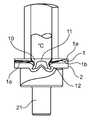
도 1 은 펀치 리벳이 도입되기에 앞서, 홀드-다운 장치와 다이 판 사이에 위치되는 2 개의 작업물 층들을 도시하고,
도 2 는 펀치 리벳이 결합부 안으로 도입된 직후의 결합부를 도시하고,
도 3 은 후속하는 펀치 리벳의 가열 및 리벳 코팅의 용융을 도시하고,
도 4 는 코팅이 절단면들에 접착되는 결합부의 후속하는 냉각을 도시하고,
도 5 는 결합 장치로부터의 제거 직전의 완료된 결합부를 도시한다.Figure 1 shows two workpiece layers positioned between the hold-down device and die plate prior to the introduction of punch rivets,
Figure 2 shows the engagement immediately after the punch rivet is introduced into the engagement,
Figure 3 shows the subsequent heating of the punch rivet and the melting of the rivet coating,
Figure 4 shows the subsequent cooling of the joint where the coating is bonded to the cutting faces,
Figure 5 shows the completed engagement immediately before removal from the engagement device.
도 1 은 제 1 작업물 층(1), 그리고 이에 결합될 제 2 작업물 층(2)을 도시하며, 이 층들은 결합 장치 안으로 도입되었고 이 결합 장치 내에 위치되었다. 그 자체로 공지된 결합 장치는 다이 판(21), 홀드-다운 장치(24) 및 스탬프(26)를 포함한다.
1 shows a
제 1 작업물 층(1)은 섬유 강화 재료로 조성되며, 그의 매트릭스(1a)에는 다중의 섬유(1b)들이 매트릭스(1a) 재료를 강화하는 목적을 위해 도입되었다. 본 섬유 강화 재료는 배향된 긴 섬유들을 갖는 유리 섬유 강화 플라스틱 또는 탄소 섬유 강화 플라스틱이다. 하지만, 원리적으로는 모든 공지된 섬유 강화 재료들이 제 1 작업물 층(1)을 위해 이용되는 것이 가능하다. 본 제 2 작업물 층(2)은 금속성 재료, 특히 철 합금, 알루미늄 합금 또는 마그네슘 합금으로 조성된다. 하지만, 원리적으로는, 다른 공지된 비섬유 강화 또는 섬유 강화 재료들이 제 2 작업물 층(2)을 위해 이용되는 것이 또한 가능하다.
The
제 2 작업물 층(2)은 다이 판(21) 상에 지지된다. 제 1 작업물 층(1)은 제 2 작업물 층(2) 상에 2 차원 방식으로 지지된다. 홀드-다운 장치(24)에 의해, 2 개의 작업물 층(1, 2)들은 결합 장치 내에서 서로에 대하여 고정된다.
The second workpiece layer (2) is supported on the die plate (21). The
펀치 리벳(10)의 형태의 연결 요소는 결합 장치 내의 결합부 위에 위치된다. 펀치 리벳(10)은 반-중공 펀치 리벳으로서 이행되지만, 수정된 실시예에서 또한 중실 리벳일 수 있다. 펀치 리벳(10)은 리벳 헤드(11) 및 리벳 섕크(12)를 포함한다. 리벳 섕크(12)에는 리벳 섕크(12)에 접착제 또는 플라스틱으로서 도포되는 바람직하게는 폴리머로 조성되는 코팅(15)이 제공된다.
The coupling element in the form of a
도 2 에서, 스탬프(26)에 의하여 힘에 의해 영향을 받는 펀치 리벳(10)이 제 1 작업물 층(1)을 통과하여 펀칭되고 제 2 작업물 층(2) 안으로 도입되는 조합된 펀칭 및 변형 작업 직후의 결합부가 예시된다. 여기서 펀치 리벳(10)은 일회용 절단 스탬프의 역할을 하고, 이러한 경우 다이 판(21)에 의해 가해지는 대항력(counterforce)에 의해 다이 판(21) 내의 몰딩 상에 펼쳐지는 점에서 또한 그 자체가 변형된다. 본 경우에, 이는 특히 제 2 작업물 층(2)을 완전히 관통하지 않으면서 일어난다. 관통 펀칭 때문에, 둘러싸는 원통형 절단면이 제 1 작업물 층(1) 내에 생성된다. 절단면의 영역 내에, 매트릭스(1a) 및 섬유(1b)들의 매트릭스 재료가 통과하여 절단되었다. 절단면의 주변 존에서, 섬유(1b)들의 섬유 단부들은 개방되어 놓이고 매트릭스(1a)의 매트릭스 재료에 의해 커버되지 않고 보호되지 않는다. 이 때문에, 섬유(1b)들 및 매트릭스(1a) 재료의 박리가 절단면에서 발생한다.
In Figure 2, the combined punching in which the punch rivet 10, which is affected by the force by the
예시적인 실시예의 변형에서, 제 1 작업물 층(1)은 제 1 작업물 층 내의 절단면이 펀치 리벳(10)에 의해 제조되지 않거나 단지 부분적으로 제조되도록, 본 발명에 따른 방법을 시작하기에 앞서 이미 예비 펀칭된다.
In a variant of the exemplary embodiment, the
도 3 에 도시된 다음의 방법 단계에서, 결합부는 스탬프(26)가 가열 가능하고, 특히 전력 또는 인덕션(induction)에 의해 가열된다는 점에서 스탬프(26)에 의해 가열된다. 대안적인 결합 장치에서, 다이 판(21) 및/또는 홀드-다운 장치(24)가 또한 가열 가능할 수 있다. 도입된 열 때문에, 펀치 리벳(10)의 리벳 섕크(12)의 코팅(15)은 용융되고 제 1 작업물 층(1) 내의 절단면을 마르지 않게 하여, 코팅이 특히 완전하게 절단면을 밀봉하게 된다.
In the next method step shown in FIG. 3, the engaging portion is heated by the
도 4 에 도시된 후속하는 단계에서, 결합부는 스탬프(26)로의 열 공급이 스위치 오프되고, 특히 활발한 냉각이 부가적으로 일어난다는 점에서 냉각된다. 이를 위해, 스탬프(26)는 이미 결합부로부터 멀어진다. 코팅(15)은 이제 제 1 작업물 층(1)의 절단면 상에서 고형화되고 따라서 섬유(1b)들의 섬유 단부들을 커버하며, 이 때문에 박리에 대항하여 보호된다.
In the subsequent step shown in FIG. 4, the coupling is cooled in that the heat supply to the
마지막 방법 단계에서, 함께 결합되는 작업물 층(1 및 2)들은 결합 장치로부터 제거된다(도 5).
In the last method step, the workpiece layers 1 and 2 to be bonded together are removed from the bonding apparatus (FIG. 5).
전술된 설명에 개시된 특징들, 청구항들 및 도면들은 개별적으로든 그리고 조합하여서든지 그 다양한 실시예들로의 본 발명의 이행에 있어서 중요하다.
The features, claims and drawings disclosed in the foregoing description are important to the implementation of the invention, either individually and in combination, in its various embodiments.
1제 1 작업물 층
1a매트릭스
1b섬유
2제 2 작업물 층
10연결 요소, 펀치 리벳
11리벳 헤드
12리벳 섕크
15코팅
21다이 판
24홀드-다운 장치
26스탬프1 First workpiece layer
1a Matrix
1b fiber
2 Second workpiece layer
10 Connecting elements, punch rivet
11 rivet head
12 Rivet shank
15 Coating
21 die plate
24 Hold-down device
26 Stamps
Claims (15)
Translated fromKoreana. 스탬프(26)에 의해, 상기 연결 요소(10)는 제 1 작업물 층(1)의 방향으로부터 그리고 스탬핑력의 가함 하에서, 그리고 제 1 작업물 층(1)에 절단면을 형성하거나 제 1 작업물 층(1)의 절단면 옆을 지나가면서 적어도 제 1 작업물 층을 통과하여 가이드되며, 특히 통과하여 펀칭되고 제 2 작업물 층을 적어도 부분적으로 관통하며,
b. 연결 요소(10)는 제 2 작업물 층(2) 상에 지지되는 다이 판(die plate)(21)에 의해 연결 요소(10) 상에 스탬핑력의 가함 하에서 변형되어, 상기 연결 요소(10)는 형상 끼워맞춤(form-fitting) 방식으로 둘 이상의 작업물 층(1, 2)들을 상호 연결하며.
c. 프로세스 동안, 상기 연결 요소(10)는 이 연결 요소(10)의 외측에 도포된 코팅(15)이 용융되고 제 1 작업물 층(1) 내의 절단면을 마르지 않게 하는 정도로 가열되고,
d. 상기 재고형화된 코팅(15)은, 냉각 프로세스 후에 제 1 작업물 층(1)의 절단면에 접착되는 것을 특징으로 하는,
작업물 층들의 결합 방법.
A method of joining two or more workpiece layers (1, 2) by introducing a joining element (10) having a coating (15) applied to the outside of the joining element (10) (1, 2) and interconnecting two or more workpiece layers (1, 2) by bonding devices (21, 24, 26) at a joint of the workpiece layers ,
a. By means of the stamp 26, the connecting element 10 can be formed from the direction of the first workpiece layer 1 and under the application of a stamping force and by forming a cut surface in the first workpiece layer 1, Passing at least partially through the first workpiece layer as it passes beside the cut surface of the layer 1 and is particularly punched through and passes through the second workpiece layer at least partially,
b. The connecting element 10 is deformed under the application of a stamping force on the connecting element 10 by means of a die plate 21 supported on the second workpiece layer 2, Interconnects two or more workpiece layers 1, 2 in a form-fitting manner.
c. During the process, the connecting element 10 is heated to such an extent that the coating 15 applied to the outside of the connecting element 10 is melted and the cutting surface in the first workpiece layer 1 is not dried,
d. Characterized in that the stocked coating (15) is adhered to the cut surface of the first workpiece layer (1) after the cooling process.
A method of bonding workpiece layers.
상기 연결 요소(10)는 코팅(15)이 용융되고 제 1 작업물 층(1)의 절단면을 완전히 밀봉하는 정도로 가열되는 것을 특징으로 하는,
작업물 층들의 결합 방법.
The method according to claim 1,
Characterized in that the connecting element (10) is heated to such an extent that the coating (15) melts and completely seals the cut surface of the first workpiece layer (1)
A method of bonding workpiece layers.
상기 방법을 시작하기에 앞서, 둘 이상의 작업물 층(1, 2)들 중 하나 이상은 결합부의 영역에서 예비 펀칭 없이 연속적으로 폐쇄된 표면을 갖는 것을 특징으로 하는,
작업물 층들의 결합 방법.
3. The method according to claim 1 or 2,
Characterized in that at least one of the two or more workpiece layers (1, 2) has a continuously closed surface, without pre-punching, in the region of the engagement part, before starting the process.
A method of bonding workpiece layers.
상기 연결 요소(10)는 관통 펀칭 연결 요소인 것을 특징으로 하는,
작업물 층들의 결합 방법.
4. The method according to any one of claims 1 to 3,
Characterized in that the connecting element (10) is a through punching connecting element.
A method of bonding workpiece layers.
상기 관통 펀칭 연결 요소(10)는 펀치 리벳인 것을 특징으로 하는,
작업물 층들의 결합 방법.
5. The method of claim 4,
Characterized in that the through punching connection element (10) is a punch rivet.
A method of bonding workpiece layers.
상기 관통 펀칭 연결 요소(10)는 반-중공 펀치 리벳이거나 또는 중실 펀치 리벳인 것을 특징으로 하는,
작업물 층들의 결합 방법.
6. The method of claim 5,
Characterized in that the through punching connection element (10) is a semi-hollow punch rivet or a solid punch rivet.
A method of bonding workpiece layers.
상기 연결 요소(10)는 관통 홀 또는 탭형(tapped) 홀을 갖는 것을 특징으로 하는,
작업물 층들의 결합 방법.
7. The method according to any one of claims 1 to 6,
Characterized in that the connecting element (10) has a through hole or a tapped hole.
A method of bonding workpiece layers.
상기 둘 이상의 작업물 층(1, 2)들 중 하나 이상은 섬유 강화 플라스틱으로 조성되는 것을 특징으로 하는,
작업물 층들의 결합 방법.
8. The method according to any one of claims 1 to 7,
Characterized in that at least one of the two or more workpiece layers (1, 2) is made of fiber-
A method of bonding workpiece layers.
상기 둘 이상의 작업물 층(1, 2)들 중 하나 이상은 금속성 재료, 특히 철 합금, 알루미늄 합금 또는 마그네슘 합금으로 조성되는 것을 특징으로 하는,
작업물 층들의 결합 방법.
9. The method according to any one of claims 1 to 8,
Characterized in that at least one of the two or more workpiece layers (1, 2) is composed of a metallic material, in particular an iron alloy, an aluminum alloy or a magnesium alloy,
A method of bonding workpiece layers.
상기 코팅(15)은 접착제 또는 플라스틱, 특히 폴리머 재료를 포함하는 것을 특징으로 하는,
작업물 층들의 결합 방법.
10. The method according to any one of claims 1 to 9,
Characterized in that the coating (15) comprises an adhesive or plastic, in particular a polymer material.
A method of bonding workpiece layers.
상기 코팅(15)은 열가소성 플라스틱으로 조성되는 것을 특징으로 하는,
작업물 층들의 결합 방법.
11. The method of claim 10,
Characterized in that the coating (15) is made of thermoplastics.
A method of bonding workpiece layers.
연결 요소(10).
A coating (15) for use in a method according to any one of the preceding claims,
The connecting element (10).
상기 결합 장치는 공구 요소들로서 다이 판(21), 홀드-다운 장치(24) 및 스탬프(26)를 포함하고, 하나 이상의 공구 요소(21, 24, 26)는 가열 가능한 것을 특징으로 하는,
결합 장치.
12. Coupling device (21, 24, 26) for use in a method according to any one of the preceding claims,
Characterized in that the coupling device comprises a die plate (21), a hold-down device (24) and a stamp (26) as tool elements and the one or more tool elements (21, 24, 26)
Coupling device.
상기 스탬프(26)는 가열 가능한 것을 특징으로 하는,
결합 장치.
14. The method of claim 13,
Characterized in that the stamp (26) is heatable.
Coupling device.
상기 결합 장치(21, 24, 26)는 온도 제어 장치를 포함하며 이 온도 제어 장치에 의해 공구 요소(21, 24, 26)의 온도가 조절될 수 있고 일정한 레벨로 유지될 수 있는 것을 특징으로 하는,
결합 장치.The method according to claim 13 or 14,
Characterized in that the coupling device (21, 24, 26) comprises a temperature control device by which the temperature of the tool element (21, 24, 26) can be adjusted and maintained at a constant level ,
Coupling device.
Applications Claiming Priority (5)
| Application Number | Priority Date | Filing Date | Title |
|---|---|---|---|
| DE102012006631.7 | 2012-03-31 | ||
| DE102012006631 | 2012-03-31 | ||
| DE102012008798.5 | 2012-04-19 | ||
| DE102012008798.5ADE102012008798B4 (en) | 2012-03-31 | 2012-04-19 | Method of joining and connecting element |
| PCT/EP2013/055430WO2013143887A1 (en) | 2012-03-31 | 2013-03-15 | Method for joining workpiece layers and connecting element and joining device |
Publications (1)
| Publication Number | Publication Date |
|---|---|
| KR20140102299Atrue KR20140102299A (en) | 2014-08-21 |
Family
ID=49154518
Family Applications (1)
| Application Number | Title | Priority Date | Filing Date |
|---|---|---|---|
| KR1020147019368ACeasedKR20140102299A (en) | 2012-03-31 | 2013-03-15 | Method for joining workpiece layers and connecting element and joining device |
Country Status (8)
| Country | Link |
|---|---|
| US (1) | US20140331478A1 (en) |
| EP (1) | EP2830790B1 (en) |
| JP (1) | JP5847321B2 (en) |
| KR (1) | KR20140102299A (en) |
| CN (1) | CN104023869B (en) |
| DE (1) | DE102012008798B4 (en) |
| IN (1) | IN2014DN03080A (en) |
| WO (1) | WO2013143887A1 (en) |
Cited By (3)
| Publication number | Priority date | Publication date | Assignee | Title |
|---|---|---|---|---|
| KR102081744B1 (en) | 2018-10-02 | 2020-02-26 | 주식회사 성우하이텍 | hybrid jointing apparatus and method for manufacturing joint structure using the same |
| KR102081742B1 (en) | 2018-10-02 | 2020-02-26 | 주식회사 성우하이텍 | hybrid jointing apparatus and method for manufacturing joint structure using the same |
| KR102081737B1 (en) | 2018-10-02 | 2020-02-26 | 주식회사 성우하이텍 | hybrid jointing apparatus and method for manufacturing joint structure using the same |
Families Citing this family (15)
| Publication number | Priority date | Publication date | Assignee | Title |
|---|---|---|---|---|
| DE102014000624B4 (en)* | 2014-01-18 | 2016-07-28 | Audi Ag | Method for joining at least two joining parts, which are overlapping at least in a joining zone, using a padding element |
| US10189113B2 (en)* | 2014-04-24 | 2019-01-29 | GM Global Technology Operations LLC | Resistance spot welding method |
| DE102015207052A1 (en) | 2015-04-17 | 2016-10-20 | Ejot Gmbh & Co. Kg | Connecting element for positive connection with at least one component |
| DE102015109255A1 (en)* | 2015-06-11 | 2016-12-15 | Profil Verbindungstechnik Gmbh & Co. Kg | Method for fastening a rivet element and corresponding fastening system |
| DE102015016912B3 (en)* | 2015-12-23 | 2017-03-02 | Technische Universität Chemnitz | Tool for producing mechanical joints of overlapping plate-shaped workpieces and mechanical joint connection |
| DE102016118109A1 (en)* | 2016-09-26 | 2018-03-29 | Newfrey Llc | Joining method for pre-hole-free connection of at least one first component with a second component |
| US10487863B2 (en)* | 2017-02-17 | 2019-11-26 | Ford Global Technologies, Llc | Castellated joint for improved adhesive coverage when using mechanical fixings and adhesive in one joint |
| CN108296369A (en)* | 2018-01-30 | 2018-07-20 | 芜湖东光奥威汽车制动系统有限公司 | A closing machine for improving production tempo |
| JP7398186B2 (en)* | 2018-05-10 | 2023-12-14 | 日産自動車株式会社 | Board joining structure and joining method |
| CN108555219B (en)* | 2018-05-14 | 2019-12-31 | 上海应用技术大学 | Self-piercing riveting device and self-piercing riveting method for semi-hollow rivets |
| CN109047620B (en)* | 2018-09-28 | 2024-04-02 | 无锡安士达五金有限公司 | Self-punching rivet |
| KR102161128B1 (en)* | 2018-12-27 | 2020-09-29 | (주)탑아이엔디 | Vehicle body assembly jig |
| CN110645249A (en)* | 2019-09-17 | 2020-01-03 | 上海纳特汽车标准件有限公司 | Rivet turning and riveting device |
| US11665755B2 (en) | 2020-05-15 | 2023-05-30 | Zhenbang Yang | Peer-to-peer communication among end user devices |
| CN112659571A (en)* | 2021-03-15 | 2021-04-16 | 长沙理工大学 | Riveting method of carbon fiber plate |
Family Cites Families (40)
| Publication number | Priority date | Publication date | Assignee | Title |
|---|---|---|---|---|
| US1872385A (en)* | 1930-04-02 | 1932-08-16 | Smith Corp A O | Connecting parts |
| US3524042A (en)* | 1967-02-17 | 1970-08-11 | Gen Electric | Method of making mechanical and welded joint |
| US3639137A (en)* | 1969-10-09 | 1972-02-01 | Ncr Co | Metal fastening coated with pressure-activatable encapsulated sealant system |
| US3878356A (en)* | 1973-09-27 | 1975-04-15 | Cleveland E Roye | Diffusion band riveting method |
| US4010519A (en)* | 1975-11-24 | 1977-03-08 | Shur-Lok Corporation | Fastener structures utilizing a thermoplastic adhesive |
| US4475389A (en)* | 1982-08-23 | 1984-10-09 | Stant Inc. | Radiator cap probe |
| US4838813A (en)* | 1988-05-10 | 1989-06-13 | Amp Incorporated | Terminator plug with electrical resistor |
| US5025128A (en)* | 1988-12-02 | 1991-06-18 | Metcal, Inc. | Rivet with integral heater |
| CA2123886A1 (en)* | 1991-11-27 | 1993-06-10 | Stuart Edmund Blacket | Improved panel clinching methods |
| US5253965A (en)* | 1992-04-13 | 1993-10-19 | Progressive Tool & Industries Co. | Piercing fastener with adhesive |
| US5680690A (en)* | 1996-02-06 | 1997-10-28 | Franklin S. Briles | Coated rivet and deformation thereof |
| DE10033149A1 (en)* | 1999-07-09 | 2001-02-01 | Profil Verbindungstechnik Gmbh | Functional element with hollow head part having same outer diameter as shank and formed with swaging and riveting features to fit into metal plate |
| DE10125559A1 (en)* | 2001-05-23 | 2002-11-28 | Basf Ag | Composite component manufacturing method, involves compression of a punched edge on a metal component into a plastic component to form a connection |
| JP2003106316A (en)* | 2001-09-28 | 2003-04-09 | Fukui Byora Co Ltd | Self boring rivet, quality-inspecting apparatus for connecting state thereof, and rivet setter provided therewith |
| DE10149633A1 (en)* | 2001-10-09 | 2003-04-10 | Basf Ag | Laminar component composed of metal and plastics sections, is produced by injection moldings and by using stamping edge or collar |
| US6694597B2 (en)* | 2002-03-08 | 2004-02-24 | General Motors Corporation | Method for riveting metal members |
| US6732420B2 (en)* | 2002-03-08 | 2004-05-11 | General Motors Corporation | Method for riveting metal members therewith |
| US6851186B2 (en)* | 2002-11-13 | 2005-02-08 | Malico, Inc. | Environmental protection concerned method for manufacturing heat sink |
| US6836948B2 (en)* | 2003-02-05 | 2005-01-04 | General Motors Corporation | Method of joining a sheet metal part to a metal tube |
| JP2004360746A (en)* | 2003-06-03 | 2004-12-24 | Nissan Motor Co Ltd | Rivet and joining method using rivets |
| US6905295B2 (en)* | 2003-07-22 | 2005-06-14 | General Motors Corporation | Blind rivet with extended adhesive reservoir |
| JP2005069451A (en)* | 2003-08-28 | 2005-03-17 | Honda Motor Co Ltd | Fastening method and fastening structure of superposed FRP plates |
| US7267736B2 (en)* | 2003-12-18 | 2007-09-11 | General Motors Corporation | Method of joining dissimilar materials |
| DE102004003909B4 (en)* | 2004-01-27 | 2010-09-09 | GM Global Technology Operations, Inc., Detroit | Press welding process for joining two or more sheets or profile parts, in particular a body segment, its use and body segment |
| JP2005321018A (en)* | 2004-05-10 | 2005-11-17 | Nissan Motor Co Ltd | Rivet and joining method using rivet |
| DE102004025492A1 (en)* | 2004-05-21 | 2009-08-06 | Volkswagen Ag | Method for joining surface materials by using a joining element such as bolts or nuts, comprises welding the joining element with the surface material under mechanical load by resistance heating or inductive heating |
| JP2006043769A (en)* | 2004-07-05 | 2006-02-16 | Nissan Motor Co Ltd | Self-piercing rivet joining method and self-piercing rivet joining apparatus |
| DE102005031917A1 (en)* | 2004-09-24 | 2006-04-13 | Böllhoff Verbindungstechnik GmbH | Method for joining and device for actuating a joining tool |
| US20080149256A1 (en)* | 2006-12-21 | 2008-06-26 | Gm Global Technology Operations, Inc. | Method and apparatus to minimize adhesive induced distortion |
| JP2008221947A (en)* | 2007-03-09 | 2008-09-25 | Mazda Motor Corp | Vehicle body joining method and its joining structure |
| DE102007030806A1 (en)* | 2007-07-03 | 2009-01-08 | Ejot Gmbh & Co. Kg | Friction welding connection of several superimposed plates |
| DE102007044635A1 (en)* | 2007-09-19 | 2009-04-02 | Böllhoff Verbindungstechnik GmbH | Self-piercing element |
| US8393068B2 (en)* | 2007-11-06 | 2013-03-12 | The Boeing Company | Method and apparatus for assembling composite structures |
| JP5055104B2 (en)* | 2007-12-18 | 2012-10-24 | 日産自動車株式会社 | Self-piercing rivet joining method and rivet joining die |
| US8087149B2 (en)* | 2008-10-09 | 2012-01-03 | GM Global Technology Operations LLC | Self-piercing rivet and method of joining with bonded riveted joints |
| JP2010188383A (en)* | 2009-02-18 | 2010-09-02 | Honda Motor Co Ltd | Rivet joining method |
| US7984919B2 (en)* | 2009-05-18 | 2011-07-26 | Zephyros, Inc. | Structural mounting insert having a non-conductive isolator |
| US20130248083A1 (en)* | 2010-12-08 | 2013-09-26 | Toyota Jidosha Kabushiki Kaisha | Method of connecting members |
| CN102248112B (en)* | 2011-06-10 | 2013-07-10 | 郑州大学 | Stirring friction riveting device and method for light metal plate |
| US20140223641A1 (en)* | 2013-02-10 | 2014-08-14 | Blake Henderson | Helmet with custom foam liner and removable / replaceable layers of crushable energy absorption material |
- 2012
- 2012-04-19DEDE102012008798.5Apatent/DE102012008798B4/ennot_activeExpired - Fee Related
- 2013
- 2013-03-15KRKR1020147019368Apatent/KR20140102299A/ennot_activeCeased
- 2013-03-15JPJP2014540523Apatent/JP5847321B2/ennot_activeExpired - Fee Related
- 2013-03-15ININ3080DEN2014patent/IN2014DN03080A/enunknown
- 2013-03-15USUS14/361,457patent/US20140331478A1/ennot_activeAbandoned
- 2013-03-15EPEP13711010.2Apatent/EP2830790B1/ennot_activeNot-in-force
- 2013-03-15CNCN201380004562.7Apatent/CN104023869B/ennot_activeExpired - Fee Related
- 2013-03-15WOPCT/EP2013/055430patent/WO2013143887A1/enactiveApplication Filing
Cited By (3)
| Publication number | Priority date | Publication date | Assignee | Title |
|---|---|---|---|---|
| KR102081744B1 (en) | 2018-10-02 | 2020-02-26 | 주식회사 성우하이텍 | hybrid jointing apparatus and method for manufacturing joint structure using the same |
| KR102081742B1 (en) | 2018-10-02 | 2020-02-26 | 주식회사 성우하이텍 | hybrid jointing apparatus and method for manufacturing joint structure using the same |
| KR102081737B1 (en) | 2018-10-02 | 2020-02-26 | 주식회사 성우하이텍 | hybrid jointing apparatus and method for manufacturing joint structure using the same |
Also Published As
| Publication number | Publication date |
|---|---|
| US20140331478A1 (en) | 2014-11-13 |
| JP2014533203A (en) | 2014-12-11 |
| IN2014DN03080A (en) | 2015-05-15 |
| JP5847321B2 (en) | 2016-01-20 |
| WO2013143887A1 (en) | 2013-10-03 |
| DE102012008798B4 (en) | 2016-01-14 |
| CN104023869A (en) | 2014-09-03 |
| EP2830790B1 (en) | 2018-06-13 |
| CN104023869B (en) | 2016-07-13 |
| EP2830790A1 (en) | 2015-02-04 |
| DE102012008798A1 (en) | 2013-10-02 |
Similar Documents
| Publication | Publication Date | Title |
|---|---|---|
| KR20140102299A (en) | Method for joining workpiece layers and connecting element and joining device | |
| JP6533855B2 (en) | Resistance welding fastener, apparatus and method | |
| JP6646679B2 (en) | Resistance welding fastener, apparatus and method for joining similar and dissimilar materials | |
| CN103702792B (en) | Joining sheet metal-type components having an intermediate layer made of thermoplastic synthetic material | |
| JP5333584B2 (en) | Member connection method | |
| CN104249215B (en) | Resistance welding fastener, device and method | |
| US8087149B2 (en) | Self-piercing rivet and method of joining with bonded riveted joints | |
| US8393519B2 (en) | Method of assembling metal parts by friction welding, with the welding temperature being controlled using thermally conductive elements | |
| CN101945725A (en) | In friction stir process, reduce the sheet material distortion | |
| JP2008168437A (en) | Heat welding equipment | |
| Wirth et al. | Analysis of the bonding behavior and joining mechanism during friction press joining of aluminum alloys with thermoplastics | |
| CN103978682B (en) | The rivet hot of the thermoplastic component of cementability connection is closed | |
| CN116141686A (en) | Ultrasonic composite riveting welding method of continuous fiber reinforced thermoplastic composite material and metal | |
| JP2012509772A (en) | Method of manufacturing lap weld joint structure and lap weld joint structure | |
| US20150156821A1 (en) | Heating element for a plastic-tube butt-welding machine, method for manufacturing a panel-type radiator, and plastic-tube butt-welding machine | |
| EP3433078A1 (en) | Device and method for producing or for interrupting a connection between at least one metal or ceramic component and a component formed from or with a thermoplastic polymer | |
| Sickert et al. | Thermal direct joining for hybrid plastic metal structures | |
| JP7159730B2 (en) | Composite manufacturing method | |
| CN104827661A (en) | Heating connection method for thermoplastic plastic adopting rivet | |
| CN110475629B (en) | Method for producing a composite of steel parts and composite of steel parts | |
| KR20110136586A (en) | Heat welding equipment | |
| CN110394993A (en) | Non-porous stamping glue riveting connection method and connection device for fiber composite laminates | |
| CN110696369A (en) | Ultrasonic welding structure and ultrasonic welding method | |
| KR20040031134A (en) | Manufacture method of velcro | |
| JP2020040368A (en) | Method for manufacturing composite body of coated metal contouring material and resin material |
Legal Events
| Date | Code | Title | Description |
|---|---|---|---|
| A201 | Request for examination | ||
| PA0105 | International application | Patent event date:20140711 Patent event code:PA01051R01D Comment text:International Patent Application | |
| PA0201 | Request for examination | ||
| PG1501 | Laying open of application | ||
| E902 | Notification of reason for refusal | ||
| PE0902 | Notice of grounds for rejection | Comment text:Notification of reason for refusal Patent event date:20150628 Patent event code:PE09021S01D | |
| E90F | Notification of reason for final refusal | ||
| PE0902 | Notice of grounds for rejection | Comment text:Final Notice of Reason for Refusal Patent event date:20160626 Patent event code:PE09021S02D | |
| E601 | Decision to refuse application | ||
| PE0601 | Decision on rejection of patent | Patent event date:20161031 Comment text:Decision to Refuse Application Patent event code:PE06012S01D Patent event date:20160626 Comment text:Final Notice of Reason for Refusal Patent event code:PE06011S02I Patent event date:20151231 Comment text:Notification of reason for refusal Patent event code:PE06011S01I Patent event date:20150628 Comment text:Notification of reason for refusal Patent event code:PE06011S01I |