KR20140098623A - Lift device - Google Patents
Lift deviceDownload PDFInfo
- Publication number
- KR20140098623A KR20140098623AKR1020130011524AKR20130011524AKR20140098623AKR 20140098623 AKR20140098623 AKR 20140098623AKR 1020130011524 AKR1020130011524 AKR 1020130011524AKR 20130011524 AKR20130011524 AKR 20130011524AKR 20140098623 AKR20140098623 AKR 20140098623A
- Authority
- KR
- South Korea
- Prior art keywords
- rope
- actuator
- fixed
- frame
- control lever
- Prior art date
- Legal status (The legal status is an assumption and is not a legal conclusion. Google has not performed a legal analysis and makes no representation as to the accuracy of the status listed.)
- Ceased
Links
- 238000004804windingMethods0.000claimsabstractdescription5
- 239000003638chemical reducing agentSubstances0.000claimsdescription6
- 238000010586diagramMethods0.000description7
- 230000000694effectsEffects0.000description2
- 238000009413insulationMethods0.000description1
- 230000007935neutral effectEffects0.000description1
Images


Classifications
- B—PERFORMING OPERATIONS; TRANSPORTING
- B66—HOISTING; LIFTING; HAULING
- B66C—CRANES; LOAD-ENGAGING ELEMENTS OR DEVICES FOR CRANES, CAPSTANS, WINCHES, OR TACKLES
- B66C13/00—Other constructional features or details
- B66C13/18—Control systems or devices
- B66C13/22—Control systems or devices for electric drives
- B—PERFORMING OPERATIONS; TRANSPORTING
- B66—HOISTING; LIFTING; HAULING
- B66C—CRANES; LOAD-ENGAGING ELEMENTS OR DEVICES FOR CRANES, CAPSTANS, WINCHES, OR TACKLES
- B66C23/00—Cranes comprising essentially a beam, boom, or triangular structure acting as a cantilever and mounted for translatory of swinging movements in vertical or horizontal planes or a combination of such movements, e.g. jib-cranes, derricks, tower cranes
- B66C23/16—Cranes comprising essentially a beam, boom, or triangular structure acting as a cantilever and mounted for translatory of swinging movements in vertical or horizontal planes or a combination of such movements, e.g. jib-cranes, derricks, tower cranes with jibs supported by columns, e.g. towers having their lower end mounted for slewing movements
- B—PERFORMING OPERATIONS; TRANSPORTING
- B66—HOISTING; LIFTING; HAULING
- B66C—CRANES; LOAD-ENGAGING ELEMENTS OR DEVICES FOR CRANES, CAPSTANS, WINCHES, OR TACKLES
- B66C2700/00—Cranes
- B66C2700/08—Electrical assemblies or electrical control devices for cranes, winches, capstans or electrical hoists
- B66C2700/085—Control actuators
Landscapes
- Engineering & Computer Science (AREA)
- Mechanical Engineering (AREA)
- Automation & Control Theory (AREA)
- Manipulator (AREA)
Abstract
Translated fromKoreanDescription
Translated fromKorean본 발명은 리프트 장치에 관한 것으로 더욱 상세하게는 하중물의 상하 이동조작이 극히 편리한 리프트 장치에 관한 것이다.
The present invention relates to a lifting device, and more particularly, to a lifting device in which a lifting operation of a load is extremely convenient.
리프트 장치는 산업 분야에 적재물 또는 하중물을 특정한 위치로 이동하기 위하여 널리 적용하는 일반적인 장치로, 적재물의 종류에 따라 다양한 형태와 기능을 갖는 것들이 제안되고 현재 사용되고 있다.The lift apparatus is a general apparatus widely applied to move the load or load to a specific position in the industrial field, and those having various forms and functions according to the type of load are proposed and are currently used.
예를 들면, 공구의 교체를 위한 암리프트 장치가 공개특허 제2009-0061815호에 개시되어 있다. 상기 특허는 공구를 파지하여 교환시키는 그리퍼 조립체를 왕복 이동시키는 자동 공구교환장치의 암 리프트 장치에 있어서, 암 리프트 장치의 프레임으로 내측이 비어있는 하우징, 상기의 하우징의 상측에 배치된 메인 서포트, 메인 서포트의 내측에 고정 배치되고 중심부에 통공이 형성된 서포트 플레이트, 통공을 통과하고 일단부에 플랜지가 형성된 로드 부재, 일단부가 로드 부재의 타단부에 연결되어 로드 부재와 일체로 직선 이동되며 타단부에 그리퍼 조립체가 구비된 암 및 서포트 플레이트와 플랜지의 사이에 배치되어 복원력이 확장되는 방향으로 작용하는 탄성수단을 포함하여 구성되어, 종래에 인장 스프링 부재에서 인장스프링 부재의 단부가 절손되는 문제점을 해소할 수 있어 종래의 암 리프트 장치에 비교하여 수명길고 장시간동안 원활하게 구동될 수 있으며, 공구 자동 교환 장치에 가해지는 부하를 경감시킬 수 있는 효과가 있다.For example, an arm lift device for tool replacement is disclosed in Japanese Patent Application Laid-Open No. 2009-0061815. The above-mentioned patent discloses an arm lift apparatus of an automatic tool changer for reciprocating a gripper assembly for gripping and exchanging a tool. The arm lift apparatus includes a housing having a hollow inside with a frame of the arm lift apparatus, a main support arranged on the upper side of the housing, A support plate which is fixed to the inside of the support and has a through hole formed at its center, a rod member which passes through the through hole and has a flange at one end thereof, a rod member which is connected at one end to the other end of the rod member, And an elastic means disposed between the arm and the support plate and the flange and acting in a direction in which the restoring force is expanded. This eliminates the problem that the end portion of the tension spring member is damaged in the conventional tension spring member Compared with the conventional arm lift device, To be driven, and there is an effect that it is possible to relieve the load on the automatic tool changer.
또한, 공압을 이용한 에어 리프트 피벗장치의 구성이 등록특허 제528078호에 개시되어 있다. 즉, 하나의 아암 단부에 결합되는 하우징; 다른 하나의 아암 단부에 결합되며 상기 하우징의 내부에 회전가능하게 결합되는 샤프트; 상기 샤프트와 연동되는 연동판; 상기 하우징과 연동되며 상기 연동판과 맞물려 상기 샤프트의 회전을 제동시키는 제동판; 상기 제동판과 결합되어 상기 제동판을 승하강시키는 피스톤; 상기 피스톤을 승강 또는 하강시켜 상기 제동판을 상기 연동판으로부터 이격시키는 공압실린더; 상기 공압실린더의 공압제거시 상기 피스톤이 원위치로 복귀되도록 하는 탄성수단; 으로 구성되는 것을 특징으로 하는 에어 리프트 피벗장치로, 작업 종료시 또는 정전시 리프트된 물건의 관성에 의한 리프트 아암의 움직임을 방지할 수 있도록 하여 정확한 위치로 이동될 수 있도록 하며, 물체의 흔들림을 방지하고, 손상이 방지되며, 안전성이 향상된 장점을 가지고 있다.Further, a configuration of an air lift pivoting device using air pressure is disclosed in Japanese Patent No. 528078. A housing coupled to one arm end; A shaft coupled to the other arm end and rotatably coupled to the interior of the housing; An interlocking plate interlocked with the shaft; A braking plate interlocked with the housing and engaged with the interlocking plate to braking the rotation of the shaft; A piston coupled with the braking plate to move up and down the braking plate; A pneumatic cylinder for lifting or lowering the piston to separate the brake plate from the interlocking plate; An elastic means for returning the piston back to its original position when pneumatic pressure is removed from the pneumatic cylinder; The air lift pivoting device can prevent the lift arm from moving due to the inertia of the lifted object when the operation is finished or during a power failure so that the lift arm can be moved to the correct position, , Damage is prevented, and safety is improved.
또한, 선박 건조 시 적용되는 선박의 화물창 코너 패널부착을 위한 리프트 장치가 등록특허 제938157호에 개시되어 있다. 상기 발명은 저면에 다수개의 바퀴가 설치되어 이동가능한 베이스 수평프레임과, 상기 베이스 프레임과 슬라이딩 되도록 결합되어 x축방향으로 연장되는 연장 수평프레임으로 구성되는 제 1수평이동부; 상기 베이스 수평프레임의 일단에 수직하게 고정설치되는 베이스 수직프레임과, 상기 베이스 수직프레임과 슬라이딩 되도록 결합되고 구동원에 의해 z축방향으로 연장되는 연장 수직프레임으로 구성되는 수직이동부; 상기 연장 수직프레임과 수직하게 결합되되 상기 연장 수직프레임과 연동하여z축방향으로 이동가능하도록 결합되는 이동수평프레임과, 상기 이동수평프레임과 슬라이딩 되도록 결합되고 구동원에 의해 x축방향으로 연장되는 연장 이동수평프레임으로 구성되는 제2 수평이동부 및 상기 연장 이동수평프레임 단부에 결합되되 구동원에 의해 그리퍼를 측면방향(z-x평면상)으로 틸팅구도하도록 결합된 측면틸팅부와 상기 측면틸팅부의 하부에 설치되어 그리퍼를 y축방향으로 직선운동하도록 결합된 직선운동부와 상기 측면틸팅부의 상부에 설치되어 그리퍼를 회전시키는 로테이팅부와 상기 로테이팅부의 상부에 설치되어 그리퍼를 정면방향(z-y평면상)으로 틸팅구도하도록 결합된 정면틸팅부로 구성되는 틸팅부를 포함하는 것을 특징으로 하는 선박의 화물창 코너 단열패널부착을 위한 리프트 장치를 제공한다.In addition, a lift apparatus for attaching a cargo hold corner panel of a ship to be used in shipbuilding is disclosed in Japanese Patent No. 938157. [ The first horizontal moving part includes a base horizontal frame having a plurality of wheels mounted on a bottom surface thereof and a movable horizontal frame coupled to the base frame to extend in the x-axis direction. A base vertical frame fixedly installed at one end of the base horizontal frame, a vertical moving part connected to the base vertical frame and slidably extended in the z-axis direction by a driving source, A moving horizontal frame coupled to the extended vertical frame so as to be movable in a z-axis direction in association with the extended vertical frame, and a moving horizontal frame coupled to the moving horizontal frame and extending in the x- A lateral tilting portion coupled to a second horizontal movement portion composed of a horizontal frame and an end portion of the extended moving horizontal frame and configured to tilt the gripper in a lateral direction (zx plane) by a driving source, The gripper is provided on the upper part of the rotating part to rotate the gripper. The gripper is provided on the upper part of the side tilting part to tilt the gripper in the front direction (zy plane) And a tilting portion constituted by a combined front tilting portion Provides a lifting device for mulchang corner insulation panel is attached.
상기한 바와 같이, 리프트 장치는 매우 다양한 분야에 적용되며, 적용되는 산업의 특징과 기능에 의하여 다른 형태의 구성들이 제시되고 있다.As described above, the lift apparatus is applied to a very wide variety of fields, and different types of configurations are presented by the characteristics and functions of the applied industry.
그러나, 상기 리프트 장치는 하중물의 이동 영역 이외에 위치하는 조작부를 사용자의 조작에 의하여 상기 리프트 장치가 구동되는 방식으로 운영된다.However, the lift apparatus is operated in such a manner that the lift apparatus is driven by a user's operation of an operating unit located in a region other than the moving region of the load.
대형물의 이송 시에는 상기의 방식이 안전을 위하여 바람직하나, 조립 라인 등에서 경량물의 이송에 사용되는 리프트 장치를 상기의 방식으로 조작하는 경우 작업 효율이 떨어지는 단점이 있으며, 특히 경량물의 정확한 이동을 위해서는 작업자가 경량물의 위치에서 조작 지시를 할 수 있으며, 또한 조작 지시에 신속하게 반응할 수 있는 새로운 방식의 리프트 장치가 필요하다.
However, there is a disadvantage in that when the lift device used for conveying a lightweight object is operated in an assembly line or the like, the operation efficiency is inferior. In particular, in order to accurately move the lightweight object, There is a need for a new type of lifting device that can give an operation instruction at the position of the lightweight item and can quickly respond to an operation instruction.
본 발명은 상기와 같은 종래 리프트 장치들의 단점을 극복하기 위하여 안출된 것으로, 하중물의 이송을 신속하고 편리하게 조작할 수 있는 리프트 장치를 제공하는 것에 그 목적이 있다.
SUMMARY OF THE INVENTION It is an object of the present invention to provide a lift device that can quickly and conveniently transfer a load of a load.
상기의 목적을 달성하기 위하여 본 발명은, 중량물을 이동하는 리프트 장치에 있어서, 상기 중량물을 포함하는 전체 중량을 지지하는 베이스; 상기 베이스에 일단이 연결되어 하방향으로 연장 형성되는 제1로프; 상기 제1로프의 타단에 연결되어 상기 제1로프를 권취 또는 해방하여 제1로프 방향으로 상하로 이동하는 액추에이터; 상기 엑추에이터와 연동하여 이동하며, 사용자의 조작에 의하여 상기 액추에이터의 작동을 위한 신호를 전송하는 조작부; 및 상기 조작부 하방에 부착되어 상기 중량물이 장착되는 고정부를 포함하는 것을 특징으로 한다.According to an aspect of the present invention, there is provided a lifting device for moving a heavy object, the lifting device including: a base supporting a total weight including the heavy object; A first rope connected at one end to the base and extending in a downward direction; An actuator connected to the other end of the first rope to move up and down in the first rope direction by winding or releasing the first rope; An operating unit that moves in conjunction with the actuator and transmits a signal for operation of the actuator by a user's operation; And a fixing part attached to the lower part of the operation part and to which the heavy object is mounted.
바람직하게는, 상기 액추에이터 하방에 연결되어 하방으로 연장형성되는 제2로프를 더 포함하며, 상기 조작부는 상기 제2로프에 길이 방향으로 이동 가능하되, 상기 제2로프 끝단에 부착된 스토퍼에 의하여 이동이 제한되게 상기 제2로프와 결합하는 것을 특징으로 한다.Preferably, the apparatus further comprises a second rope connected to the lower portion of the actuator and extending downward, wherein the operating portion is movable in the longitudinal direction to the second rope, and is moved by a stopper attached to the second rope end So that the second rope is limited.
바람직하게는, 상기 조작부는 상기 액추에이터 하방에 직결되는 것을 특징으로 한다.Preferably, the operating portion is directly under the actuator.
바람직하게는, 상기 베이스는 지면에 고정되는 수직부와 상기 수직부 상단에 회전 고정되는 수평부로 구분되며, 상기 제1로프의 일 끝단은 상기 제1로프에 고정되는 것을 특징으로 한다.Preferably, the base is divided into a vertical portion fixed to the ground and a horizontal portion rotatably fixed to the upper end of the vertical portion, and one end of the first rope is fixed to the first rope.
바람직하게는, 상기 액추에이터는; 상기 제1로프의 타단이 고정되며, 회전에 의하여 상기 제1로프를 권취하는 풀리; 상기 풀리에 연결되어 풀리를 회전하는 감속기; 상기 감속기에 회전력을 전달하는 모터; 및 상기 모터의 동작을 제어하는 제어장치를 포함하는 것을 특징으로 한다.Advantageously, the actuator comprises: A pulley fixing the other end of the first rope and winding the first rope by rotation; A speed reducer connected to the pulley to rotate the pulley; A motor for transmitting a rotational force to the speed reducer; And a control device for controlling the operation of the motor.
바람직하게는, 상기 조작부는: 장착되는 중량물의 하중을 지지할 수 있는 강성을 갖는 프레임; 상기 프레임에 돌출형성되는 복수의 돌출바; 상기 각 돌출바 끝단에 제2로프를 수용하는 환형부; 및 상기 환형부의 일부가 절개되며, 상기 절개부에 고정 및 분리되는 분리부를 포함하는 것을 특징으로 한다.Preferably, the operating portion includes: a frame having rigidity capable of supporting a load of a weight to be mounted; A plurality of protruding bars protruding from the frame; An annular portion receiving the second rope at an end of each of the projecting bars; And a separating portion which is cut and fixed to the cut-out portion of the annular portion.
더욱 바람직하게는, 상기 프레임에 요동 회전하도록 회전 고정되는 조절 레버; 상기 조절 레버의 회전부에 고정되어 조절 레버의 각도를 감지하는 센서; 및 상기 조절 레버와 프레임 사이에 부착되어 사용자가 조작하지 않은 경우 일정한 각도로 고정되도록 하는 스프링을 더 포함하는 것을 특징으로 한다.More preferably, the adjustment lever is rotatably fixed so as to swing in the frame; A sensor fixed to a rotating portion of the control lever to detect an angle of the control lever; And a spring attached between the control lever and the frame and fixed at a predetermined angle when the user does not operate the control lever.
더욱 바람직하게는, 상기 조절 레버는 조작의 편리성을 위하여 측면에 연결봉을 더 포함하는 것을 특징으로 한다.More preferably, the control lever further comprises a connecting rod on the side for convenience of operation.
바람직하게는, 상기 제어장치는 상기 센서의 신호를 기초로 상기 모터를 정회전, 역회전 및 중지를 선택적으로 제어하는 것을 특징으로 한다.Preferably, the control device selectively controls forward rotation, reverse rotation, and stop of the motor based on a signal of the sensor.
바람직하게는, 상기 조작부의 하부에는 중량물을 고정하는 고정부를 포함하며, 상기 고정부에서 중량물은 상기 환형부의 중심 축 상에 고정되는 것을 특징으로 한다.
Preferably, a lower portion of the operating portion includes a fixing portion for fixing the heavy object, and the heavy object is fixed on the central axis of the annular portion.
본 발명에 따른 리프트 장치는 중량물이 그립되는 곳에 조작부가 위치하여 중량물의 그립이 매우 정교하고, 조작부의 작동 구조 또한 간단하여 사용자의 조작이 편리하며, 중량물의 무게를 감지하여 무게와 연동하여 작동하므로, 신속하게 작동하는 효과가 있다.
The lift device according to the present invention is operated with the weight of the heavy object gripped by the grip portion of the heavy object, and the operation structure of the operation portion is simple and easy to operate by the user. , It has the effect of working quickly.
도 1은 본 발명에 따른 리프트 장치의 구성도이며,
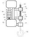
도 2는 도 1에 도시된 액추에이터의 구성도이며,
도 3은 도 1에 도시된 액추에이터의 이동을 설명하는 구성도이며,
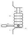
도 4는 도 1에 도시된 조작부의 구성도이며,
도 5는 도 1에 도시된 조작부의 또 다른 실시예의 구성도이며,
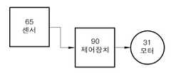
도 6은 도 1의 액추에이터에 포함된 제어장치의 구성도이며,
도 7은 도 1에 도시된 조절 레버의 작동 상태를 나타내는 구성도이다.1 is a configuration diagram of a lift apparatus according to the present invention,
Fig. 2 is a configuration diagram of the actuator shown in Fig. 1,
FIG. 3 is a diagram illustrating the movement of the actuator shown in FIG. 1,
Fig. 4 is a configuration diagram of the operating portion shown in Fig. 1,
5 is a configuration diagram of another embodiment of the operation portion shown in Fig. 1,
Fig. 6 is a configuration diagram of the control device included in the actuator of Fig. 1,
Fig. 7 is a configuration diagram showing an operating state of the control lever shown in Fig. 1. Fig.
이하 본 발명에 따른 바람직한 실시예를 첨부한 도면을 참조하여 구체적으로 설명한다.Hereinafter, preferred embodiments of the present invention will be described in detail with reference to the accompanying drawings.
본 발명에 따른 리프트 장치(100)는 도 1에 도시된 바와 같이, 베이스(10), 상기 베이스(10)의 끝단에 연결되는 제1로프(20), 상기 제1로프(20)의 끝단에 연결되어 상기 제1로프(20)의 길이를 조절하는 액추에이터(30), 상기 액추에이터(30) 하단에 연결되는 제2로프(22), 상기 제2로프(22)에 삽입 연결되며, 상기 액추에이터(30)의 동작을 제어하는 조작부(50), 상기 조작부(50)의 하단에 연결되는 고정부(80)를 포함하여 구성된다.1, a
먼저, 상기 베이스(10)는 수평부(11)와 수직부(12)로 구성되며, 상기 수직부(12)는 지면에 고정되고, 상기 수평부(11)는 상기 수직부(12) 끝단에 고정되나, 필요한 경우 리프트 장치(100)의 작업 영역 확대를 위하여, 상기 수평부(11)가 상기 수직부(12)를 중심으로 회전 가능하게 연결될 수도 있다.The
또한, 필요한 경우, 상기 베이스(10)는 단순히 건물에 고정되어 있는 구조물로 대체할 수도 있다.Also, if necessary, the
상기 베이스(10)에는 제1로프(20)의 일단이 연결된다. 상기 제1로프(20)는 상기 베이스(10)의 수평부(11) 끝단에 연결될 수도 있으며, 필요한 경우, 수평부(11) 끝단에 가이드 롤러(13)를 통하여 수직부(12)에 연결될 수도 있다.One end of the
상기 제1로프(20)는 액추에이터(30), 조작부(50) 등을 포함하는 부재의 무게와 최대 중량물의 무게를 지지할 수 있는 강성을 갖도록 직경을 구성한다.The
한편, 상기 제1로프(20)의 타단은 액추에이터(30)에 연결된다. 상기 액추에이터(30)는 도 2에 도시된 바와 같이, 모터(31), 감속기(32) 및 풀리(33)로 구성되며, 상기 풀리(33)에 상기 제1로프(20)의 타단이 고정되고, 상기 모터(31)가 회전하는 경우 상기 풀리(33)에 상기 제1로프(20)가 귄취 또는 해방되며, 따라서, 도 3에 도시된 바와 같이, 상기 액추에이터(30)는 상기 제1로프(20) 방향으로 상하 이동한다.The other end of the
필요한 경우 상기 감속기(32)에는 록킹 기능을 부여하여 모터(31)에 별도의 동력이 인가되지 않은 경우에도 하부로 이동하지 않도록 구성할 수 있다.If necessary, the
상기 액추에이터(30)는 상기 제1로프(20)의 끝단에 매달리는 형태이므로, 제로프(20)가 액추에이터(30)의 무게중심 라인에 연결되도록 구성하는 것이 바람직하며, 또한 상기 액추에이터(30)의 외부 케이스는 중량물의 하중이 직접 작용하므로, 최대 중량물을 무리 없이 지지할 수 있는 강성을 가지도록 구성한다.It is preferable that the
상기 액추에이터(30)의 하면에는 제2로프(22)의 일단이 연결된다. 상기 제2로프(22)는 작업중 길이의 변화가 발생하지 않으므로, 후술하는 조작부(50)가 삽입되어 위치할 수 있는 정도의 길이로 구성하는 것이 바람직하며, 역시 최대 중량물의 지지할 수 있는 강성으로 구성한다.And one end of the
상기 제2로프(22) 타단 즉, 하방 끝단에는 스토퍼(23)가 고정된다. 상기 스토퍼(23)는 후술하는 조작부(50)를 지지하는 역할을 하고, 상기 주작부(50)는 중량물을 지지하므로, 최대 중량물을 지지할 수 있을 정도의 강성구조로 상기 제2로프(22)에 결합한다.A
한편, 상기 제2로프(22)에는 조작부(50)가 제2로프(22)의 상하로 이동 가능하되, 하방으로는 상기 스토퍼(23)에 의하여 제한되는 형태로 상기 조작부(50)에 결합한다.The
상기 조작부(50)는 도 4에 도시된 바와 같이, 조작부(50)의 강성을 유지하며, 조작부(50)에 인가되는 하중물을 지지하는 프레임(51), 상기 프레임(51)의 일측면에 부착되어 상기 제2로프(22)에 삽입되는 이동부(52), 상기 프레임(51) 상에 설치되어 요동 운동을 하는 조절 레버(60)를 포함하여 구성된다.4, the
또한 조작부(50)는 상기 조절 레버(60)의 신호를 상기 액추에이터(30)로 전송하는 신호 케이블(59)을 포함한다.The
상기 프레임(51)은 내부에 사각 테두리를 갖는 형태로 구성하며, 상하단에는 필요한 장치를 수용하는 부재가 장착되는 형태로 구성되나, 전체 하중을 지지할 수 있는 어떠한 형태도 무방하다.The
상기 프레임(51)의 측면에는 이동부(52)가 부착되며, 상기 이동부(52)는 복수의 돌출바(53)와 상기 돌출바(53) 끝단에 형성되는 환형부(54)로 구성되고, 상기 환형부(54)의 일부는 분리 또는 부착될 수 있는 분리부(55)를 포함하여 구성된다.A moving part 52 is attached to the side surface of the
상기 제2로프(22)는 상기 환형부(54)에 삽입되고, 상기 제2로프(22)가 삽입되는 경우 상기 분리부(55)를 상기 환형부(54)에서 분리하고, 제2로프(22)의 삽입이 완료된 경우 상기 분리부(55)를 상기 환형부(54)에 부착하여 조작부(50)가 제2로프(22)에서 이탈되는 것을 방지한다.The
또한 상기 하단의 환형부(54)는 상기 스토퍼(23)에 의하여 상기 조작부(50)가 제2로프(22) 하방으로 이탈되는 것을 방지한다.The lower end
한편, 상기 조절 레버(60)는 상기 프레임(51)과 회전축(61)을 중심으로 요동 운동하도록 결합한다.Meanwhile, the
필요한 경우 상기 조절 레버(60) 내부에 통공을 형성하고 상기 통공에 상기 프레임(51)의 일부가 삽입되는 형태로 구현할 수 있다.If necessary, a through hole may be formed in the
상기 조절 레버(60)는 2개의 스프링(62)을 상기 프레임(51)과 연결하여 사용자가 조작하지 않는 경우 수직으로 기립되게 구성한다.The
상기 회전축(61)에는 회전각도를 감지하는 센서(65)를 부착하여 상기 조절 레버(60)의 회전 각도를 인식한다.A
상기 센서(65)는 필요한 경우 조절 레버(60)의 좌우측 회전을 인식하도록 2개의 리밋 스위치로도 구현할 수 있다.The
또한, 필요한 경우 상기 조절 레버(60)의 측면에는 도 5에 도시된 바와 같이, 연결봉(66)을 부착하여 편리하게 조절 레버(60)를 조절할 수 있도록 구성할 수도 있다.If necessary, a connecting
한편, 상기 프레임(51)의 하방에는 고정부(80)가 부착된다. 상기 고정부(80)는 상기 이동부(52)의 환형부(54)와 동일한 축선으로 후크(82)를 결합할 수 있는 결합부(81)가 형성된다.On the other hand, a fixing
따라서 중량물은 상기 후크(82)에 결합하고, 중량물의 자중은 조작부(50), 제2로프(22), 액추에이터(30), 제1로프(20)를 거쳐 베이스(10)로 전달된다.Accordingly, the heavy object is coupled to the
필요한 경우 상기 조작부(50)는 상기 제2루프(22) 없이 바로 상기 액추에이터(30)에 연결될 수 있다.If desired, the operating
이때는 상기 이동부(52)의 구성은 생략되며, 상기 고정부(80)는 후크(82)가 조작부(50)의 수직 중심축에 위치하도록 형태가 변경될 수 있다.At this time, the configuration of the moving part 52 is omitted, and the fixing
한편, 상기 액추에이터(30)에는 제어장치(90)를 포함하며, 상기 제어장치(90)는 도 6에 도시된 바와 같이, 센서(65)의 신호에 의하여 상기 모터(31)를 구동하며, 필요한 경우 액추에이터(30)의 이동을 감지하여 최대 이동 및 최소 이동 점에서 모터(31)의 동작이 정지될 수 있는 안전 구성도 포함할 수 있다.The
상기 조절 레버(60)는 도 7에 도시된 바와 같이, 좌방향으로 회전 시 리프트 장치(100)가 상승하고, 우방향으로 회전 시 리프트 장치(100)가 하강하며, 중앙에 위치하는 경우 이동하지 않는 중립 형태로 구현할 수 있다.As shown in FIG. 7, the
따라서, 사용자는 상기 조절 레버(60)의 각도만 조절하면, 조작부(50) 하방에 위치하는 후크(82)에 중량물을 상하로 이동하고, 측면으로 이동시에는 전체 조작부(50)를 측면으로 밀면 중량물을 손쉽게 이동할 수 있고, 중량물의 근처에서 리프트 장치(100)를 조작하므로, 신속하고 정확하게 중량물을 이동할 수 있는 특징이 있다.
Therefore, when the angle of the
이상에서는 본 발명을 특정의 바람직한 실시예에 대하여 도시하고 설명하였으나, 본 발명은 이러한 실시예에 한정되지 않으며, 당해 발명이 속하는 기술분야에서 통상의 지식을 가진 자가 특허청구범위에서 청구하는 본 발명의 기술적 사상을 벗어나지 않는 범위 내에서 실시할 수 있는 다양한 형태의 실시예들을 모두 포함한다.
While the present invention has been particularly shown and described with reference to exemplary embodiments thereof, it is to be understood that the invention is not limited to the disclosed exemplary embodiments, And all of the various forms of embodiments that can be practiced without departing from the technical spirit.
10: 베이스 11: 수평부
12: 수직부 13: 가이드 롤러
20: 제1로프 22: 제2로프
23: 스토퍼 30: 액추에이터
31: 모터 32: 감속기
33: 풀리 50: 조작부
51: 프레임 52: 이동부
53: 돌출바 54: 환형부
55: 분리부 59: 신호 케이블
60: 조절레버 61: 회전축
62: 스프링 65: 센서
66: 연결봉 80: 고정부
81: 결합부 82: 후크
90: 제어장치 100: 리프트 장치10: Base 11: Horizontal part
12: vertical portion 13: guide roller
20: first rope 22: second rope
23: stopper 30: actuator
31: motor 32: speed reducer
33: pulley 50:
51: frame 52: moving part
53: protruding bar 54: annular part
55: Separator 59: Signal cable
60: Control lever 61:
62: spring 65: sensor
66: connecting rod 80:
81: engaging portion 82: hook
90: Control device 100: Lift device
Claims (10)
Translated fromKorean상기 중량물을 포함하는 전체 중량을 지지하는 베이스;
상기 베이스에 일단이 연결되어 하방향으로 연장 형성되는 제1로프;
상기 제1로프의 타단에 연결되어 상기 제1로프를 권취 또는 해방하여 제1로프 방향으로 상하로 이동하는 액추에이터;
상기 엑추에이터와 연동하여 이동하며, 사용자의 조작에 의하여 상기 액추에이터의 작동을 위한 신호를 전송하는 조작부; 및
상기 조작부 하방에 부착되어 상기 중량물이 장착되는 고정부를 포함하는 것을 특징으로 하는 리프트 장치.
A lift apparatus for moving heavy objects,
A base for supporting the entire weight including the weight;
A first rope connected at one end to the base and extending in a downward direction;
An actuator connected to the other end of the first rope to move up and down in the first rope direction by winding or releasing the first rope;
An operating unit that moves in conjunction with the actuator and transmits a signal for operation of the actuator by a user's operation; And
And a fixing part attached to the lower part of the operation part to mount the heavy object.
[2] The apparatus according to claim 1, further comprising a second rope connected to the lower portion of the actuator and extending downward, wherein the operating portion is movable in the longitudinal direction to the second rope, So that movement of the second rope is restricted.
The lift apparatus according to claim 1, wherein the operating portion is directly connected to the lower portion of the actuator.
The lift apparatus according to claim 1, wherein the base is divided into a vertical part fixed to the ground and a horizontal part rotatably fixed to an upper end of the vertical part, and one end of the first rope is fixed to the first rope.
상기 제1로프의 타단이 고정되며, 회전에 의하여 상기 제1로프를 권취하는 풀리;
상기 풀리에 연결되어 풀리를 회전하는 감속기;
상기 감속기에 회전력을 전달하는 모터; 및
상기 모터의 동작을 제어하는 제어장치를 포함하는 것을 특징으로 하는 리프트 장치.
The actuator according to claim 1, wherein the actuator comprises:
A pulley fixing the other end of the first rope and winding the first rope by rotation;
A speed reducer connected to the pulley to rotate the pulley;
A motor for transmitting a rotational force to the speed reducer; And
And a control device for controlling the operation of the motor.
장착되는 중량물의 하중을 지지할 수 있는 강성을 갖는 프레임;
상기 프레임에 돌출형성되는 복수의 돌출바;
상기 각 돌출바 끝단에 제2로프를 수용하는 환형부; 및
상기 환형부의 일부가 절개되며, 상기 절개부에 고정 및 분리되는 분리부를 포함하는 것을 특징으로 하는 리프트 장치.
[2] The apparatus according to claim 1,
A frame having rigidity capable of supporting a load of a weight to be mounted;
A plurality of protruding bars protruding from the frame;
An annular portion receiving the second rope at an end of each of the projecting bars; And
And a separating portion which is formed by cutting a part of the annular portion and is fixed to and separated from the incising portion.
상기 조절 레버의 회전부에 고정되어 조절 레버의 각도를 감지하는 센서; 및
상기 조절 레버와 프레임 사이에 부착되어 사용자가 조작하지 않은 경우 일정한 각도로 고정되도록 하는 스프링을 더 포함하는 것을 특징으로 하는 리프트 장치.
7. The apparatus of claim 6, further comprising: an adjustment lever that is rotationally fixed to swing in the frame;
A sensor fixed to a rotating portion of the control lever to detect an angle of the control lever; And
Further comprising a spring attached between the control lever and the frame for fixing the control lever at a predetermined angle when the control lever is not operated by a user.
The lift apparatus according to claim 7, wherein the adjustment lever further includes a connecting rod on a side surface for convenience of operation.
8. The lift apparatus according to claim 7, wherein the control device selectively controls forward, reverse, and stop of the motor based on a signal of the sensor.
The lift apparatus according to claim 7, wherein the operating section includes a fixing section for fixing a heavy object to a lower portion thereof, wherein the heavy object is fixed on the central axis of the annular section.
Priority Applications (1)
| Application Number | Priority Date | Filing Date | Title |
|---|---|---|---|
| KR1020130011524AKR20140098623A (en) | 2013-01-31 | 2013-01-31 | Lift device |
Applications Claiming Priority (1)
| Application Number | Priority Date | Filing Date | Title |
|---|---|---|---|
| KR1020130011524AKR20140098623A (en) | 2013-01-31 | 2013-01-31 | Lift device |
Publications (1)
| Publication Number | Publication Date |
|---|---|
| KR20140098623Atrue KR20140098623A (en) | 2014-08-08 |
Family
ID=51745371
Family Applications (1)
| Application Number | Title | Priority Date | Filing Date |
|---|---|---|---|
| KR1020130011524ACeasedKR20140098623A (en) | 2013-01-31 | 2013-01-31 | Lift device |
Country Status (1)
| Country | Link |
|---|---|
| KR (1) | KR20140098623A (en) |
Cited By (2)
| Publication number | Priority date | Publication date | Assignee | Title |
|---|---|---|---|---|
| KR20200055443A (en)* | 2018-11-13 | 2020-05-21 | 주식회사 코닥트 | Rope type elevator apparatus |
| KR20210105461A (en)* | 2020-02-18 | 2021-08-27 | 현대로템 주식회사 | Handles for heavy loading devices |
- 2013
- 2013-01-31KRKR1020130011524Apatent/KR20140098623A/ennot_activeCeased
Cited By (2)
| Publication number | Priority date | Publication date | Assignee | Title |
|---|---|---|---|---|
| KR20200055443A (en)* | 2018-11-13 | 2020-05-21 | 주식회사 코닥트 | Rope type elevator apparatus |
| KR20210105461A (en)* | 2020-02-18 | 2021-08-27 | 현대로템 주식회사 | Handles for heavy loading devices |
Similar Documents
| Publication | Publication Date | Title |
|---|---|---|
| CN102001593B (en) | Crane | |
| JP2012111570A (en) | Suspended-freight turning device | |
| KR20140098623A (en) | Lift device | |
| CN103732521B (en) | With the emergency braking device of hand brake system | |
| JPWO2018179211A1 (en) | Pit ladder equipment for elevators | |
| KR101610928B1 (en) | Magnetic lift device for rotation of heavyweight object | |
| CN104310232B (en) | Amplitude variation type gantry crane device | |
| KR101775500B1 (en) | Safety apparatus for auto tong using balance device | |
| JP2018104110A (en) | crane | |
| CN215326572U (en) | Hoisting device | |
| JP2004161469A (en) | crane | |
| CN108916584A (en) | A kind of circular mechanism of camera multi-angle regulation | |
| JP2016067299A (en) | Portable work machine | |
| JP2007154643A (en) | Self-traveling processing apparatus | |
| JP7275761B2 (en) | Work machine lifting system | |
| EP1828036B1 (en) | Apparatus for handling loads | |
| KR102700927B1 (en) | Weight balance lifter with duplex control | |
| JP5944444B2 (en) | Heavy work lifting device | |
| KR100841946B1 (en) | Rail Type Air Balance Lifter | |
| KR20200007552A (en) | Permanent magnet fixed type conveying device | |
| KR20210020222A (en) | Intelligent lifting apparatus | |
| KR20160113870A (en) | Apparatus for working on heights and mounted on a crane | |
| JP2007167919A (en) | Die fitting device | |
| JP6208578B2 (en) | Crane equipment | |
| KR20210031064A (en) | Intelligent lifting apparatus |
Legal Events
| Date | Code | Title | Description |
|---|---|---|---|
| A201 | Request for examination | ||
| PA0109 | Patent application | Patent event code:PA01091R01D Comment text:Patent Application Patent event date:20130131 | |
| PA0201 | Request for examination | ||
| E902 | Notification of reason for refusal | ||
| PE0902 | Notice of grounds for rejection | Comment text:Notification of reason for refusal Patent event date:20140528 Patent event code:PE09021S01D | |
| PG1501 | Laying open of application | ||
| E601 | Decision to refuse application | ||
| PE0601 | Decision on rejection of patent | Patent event date:20141029 Comment text:Decision to Refuse Application Patent event code:PE06012S01D Patent event date:20140528 Comment text:Notification of reason for refusal Patent event code:PE06011S01I |