KR20140095529A - Optical readable code support and capsule for preparing a beverage having such code support providing an enhanced readable optical signal - Google Patents
Optical readable code support and capsule for preparing a beverage having such code support providing an enhanced readable optical signalDownload PDFInfo
- Publication number
- KR20140095529A KR20140095529AKR1020147014879AKR20147014879AKR20140095529AKR 20140095529 AKR20140095529 AKR 20140095529AKR 1020147014879 AKR1020147014879 AKR 1020147014879AKR 20147014879 AKR20147014879 AKR 20147014879AKR 20140095529 AKR20140095529 AKR 20140095529A
- Authority
- KR
- South Korea
- Prior art keywords
- light
- capsule
- surface portions
- readable code
- code support
- Prior art date
- Legal status (The legal status is an assumption and is not a legal conclusion. Google has not performed a legal analysis and makes no representation as to the accuracy of the status listed.)
- Granted
Links
Images


Classifications
- B—PERFORMING OPERATIONS; TRANSPORTING
- B65—CONVEYING; PACKING; STORING; HANDLING THIN OR FILAMENTARY MATERIAL
- B65D—CONTAINERS FOR STORAGE OR TRANSPORT OF ARTICLES OR MATERIALS, e.g. BAGS, BARRELS, BOTTLES, BOXES, CANS, CARTONS, CRATES, DRUMS, JARS, TANKS, HOPPERS, FORWARDING CONTAINERS; ACCESSORIES, CLOSURES, OR FITTINGS THEREFOR; PACKAGING ELEMENTS; PACKAGES
- B65D85/00—Containers, packaging elements or packages, specially adapted for particular articles or materials
- B65D85/70—Containers, packaging elements or packages, specially adapted for particular articles or materials for materials not otherwise provided for
- B65D85/804—Disposable containers or packages with contents which are mixed, infused or dissolved in situ, i.e. without having been previously removed from the package
- B65D85/8043—Packages adapted to allow liquid to pass through the contents
- A—HUMAN NECESSITIES
- A47—FURNITURE; DOMESTIC ARTICLES OR APPLIANCES; COFFEE MILLS; SPICE MILLS; SUCTION CLEANERS IN GENERAL
- A47J—KITCHEN EQUIPMENT; COFFEE MILLS; SPICE MILLS; APPARATUS FOR MAKING BEVERAGES
- A47J31/00—Apparatus for making beverages
- A47J31/44—Parts or details or accessories of beverage-making apparatus
- A47J31/4492—Means to read code provided on ingredient pod or cartridge
- B—PERFORMING OPERATIONS; TRANSPORTING
- B29—WORKING OF PLASTICS; WORKING OF SUBSTANCES IN A PLASTIC STATE IN GENERAL
- B29C—SHAPING OR JOINING OF PLASTICS; SHAPING OF MATERIAL IN A PLASTIC STATE, NOT OTHERWISE PROVIDED FOR; AFTER-TREATMENT OF THE SHAPED PRODUCTS, e.g. REPAIRING
- B29C45/00—Injection moulding, i.e. forcing the required volume of moulding material through a nozzle into a closed mould; Apparatus therefor
- B29C45/17—Component parts, details or accessories; Auxiliary operations
- B29C45/26—Moulds
- B29C45/37—Mould cavity walls, i.e. the inner surface forming the mould cavity, e.g. linings
- B29C45/372—Mould cavity walls, i.e. the inner surface forming the mould cavity, e.g. linings provided with means for marking or patterning, e.g. numbering articles
- B—PERFORMING OPERATIONS; TRANSPORTING
- B65—CONVEYING; PACKING; STORING; HANDLING THIN OR FILAMENTARY MATERIAL
- B65D—CONTAINERS FOR STORAGE OR TRANSPORT OF ARTICLES OR MATERIALS, e.g. BAGS, BARRELS, BOTTLES, BOXES, CANS, CARTONS, CRATES, DRUMS, JARS, TANKS, HOPPERS, FORWARDING CONTAINERS; ACCESSORIES, CLOSURES, OR FITTINGS THEREFOR; PACKAGING ELEMENTS; PACKAGES
- B65D25/00—Details of other kinds or types of rigid or semi-rigid containers
- B65D25/20—External fittings
- B65D25/205—Means for the attachment of labels, cards, coupons or the like
- B—PERFORMING OPERATIONS; TRANSPORTING
- B65—CONVEYING; PACKING; STORING; HANDLING THIN OR FILAMENTARY MATERIAL
- B65D—CONTAINERS FOR STORAGE OR TRANSPORT OF ARTICLES OR MATERIALS, e.g. BAGS, BARRELS, BOTTLES, BOXES, CANS, CARTONS, CRATES, DRUMS, JARS, TANKS, HOPPERS, FORWARDING CONTAINERS; ACCESSORIES, CLOSURES, OR FITTINGS THEREFOR; PACKAGING ELEMENTS; PACKAGES
- B65D85/00—Containers, packaging elements or packages, specially adapted for particular articles or materials
- B65D85/70—Containers, packaging elements or packages, specially adapted for particular articles or materials for materials not otherwise provided for
- B65D85/804—Disposable containers or packages with contents which are mixed, infused or dissolved in situ, i.e. without having been previously removed from the package
- B65D85/8043—Packages adapted to allow liquid to pass through the contents
- B65D85/8058—Coding means for the contents
- G—PHYSICS
- G06—COMPUTING OR CALCULATING; COUNTING
- G06K—GRAPHICAL DATA READING; PRESENTATION OF DATA; RECORD CARRIERS; HANDLING RECORD CARRIERS
- G06K19/00—Record carriers for use with machines and with at least a part designed to carry digital markings
- G06K19/06—Record carriers for use with machines and with at least a part designed to carry digital markings characterised by the kind of the digital marking, e.g. shape, nature, code
- G06K19/06009—Record carriers for use with machines and with at least a part designed to carry digital markings characterised by the kind of the digital marking, e.g. shape, nature, code with optically detectable marking
- G06K19/06018—Record carriers for use with machines and with at least a part designed to carry digital markings characterised by the kind of the digital marking, e.g. shape, nature, code with optically detectable marking one-dimensional coding
- G06K19/06028—Record carriers for use with machines and with at least a part designed to carry digital markings characterised by the kind of the digital marking, e.g. shape, nature, code with optically detectable marking one-dimensional coding using bar codes
- G—PHYSICS
- G06—COMPUTING OR CALCULATING; COUNTING
- G06K—GRAPHICAL DATA READING; PRESENTATION OF DATA; RECORD CARRIERS; HANDLING RECORD CARRIERS
- G06K19/00—Record carriers for use with machines and with at least a part designed to carry digital markings
- G06K19/06—Record carriers for use with machines and with at least a part designed to carry digital markings characterised by the kind of the digital marking, e.g. shape, nature, code
- G06K19/06009—Record carriers for use with machines and with at least a part designed to carry digital markings characterised by the kind of the digital marking, e.g. shape, nature, code with optically detectable marking
- G06K19/06046—Constructional details
- B—PERFORMING OPERATIONS; TRANSPORTING
- B29—WORKING OF PLASTICS; WORKING OF SUBSTANCES IN A PLASTIC STATE IN GENERAL
- B29K—INDEXING SCHEME ASSOCIATED WITH SUBCLASSES B29B, B29C OR B29D, RELATING TO MOULDING MATERIALS OR TO MATERIALS FOR MOULDS, REINFORCEMENTS, FILLERS OR PREFORMED PARTS, e.g. INSERTS
- B29K2023/00—Use of polyalkenes or derivatives thereof as moulding material
- B29K2023/04—Polymers of ethylene
- B29K2023/06—PE, i.e. polyethylene
- B—PERFORMING OPERATIONS; TRANSPORTING
- B29—WORKING OF PLASTICS; WORKING OF SUBSTANCES IN A PLASTIC STATE IN GENERAL
- B29K—INDEXING SCHEME ASSOCIATED WITH SUBCLASSES B29B, B29C OR B29D, RELATING TO MOULDING MATERIALS OR TO MATERIALS FOR MOULDS, REINFORCEMENTS, FILLERS OR PREFORMED PARTS, e.g. INSERTS
- B29K2023/00—Use of polyalkenes or derivatives thereof as moulding material
- B29K2023/10—Polymers of propylene
- B29K2023/12—PP, i.e. polypropylene
- B—PERFORMING OPERATIONS; TRANSPORTING
- B29—WORKING OF PLASTICS; WORKING OF SUBSTANCES IN A PLASTIC STATE IN GENERAL
- B29L—INDEXING SCHEME ASSOCIATED WITH SUBCLASS B29C, RELATING TO PARTICULAR ARTICLES
- B29L2011/00—Optical elements, e.g. lenses, prisms
- B—PERFORMING OPERATIONS; TRANSPORTING
- B29—WORKING OF PLASTICS; WORKING OF SUBSTANCES IN A PLASTIC STATE IN GENERAL
- B29L—INDEXING SCHEME ASSOCIATED WITH SUBCLASS B29C, RELATING TO PARTICULAR ARTICLES
- B29L2031/00—Other particular articles
- B29L2031/712—Containers; Packaging elements or accessories, Packages
- B29L2031/7174—Capsules
Landscapes
- Engineering & Computer Science (AREA)
- Mechanical Engineering (AREA)
- Theoretical Computer Science (AREA)
- Physics & Mathematics (AREA)
- General Physics & Mathematics (AREA)
- Food Science & Technology (AREA)
- Manufacturing & Machinery (AREA)
- Apparatus For Making Beverages (AREA)
- Food-Manufacturing Devices (AREA)
- General Preparation And Processing Of Foods (AREA)
- Tea And Coffee (AREA)
- Investigating Materials By The Use Of Optical Means Adapted For Particular Applications (AREA)
- Moulds For Moulding Plastics Or The Like (AREA)
- Investigating Or Analysing Materials By Optical Means (AREA)
- Developing Agents For Electrophotography (AREA)
Abstract
Translated fromKoreanDescription
Translated fromKorean본원은 음료 제조 분야에 관한 것으로서, 특히 음료 제조 머신에서 음료를 제조하기 위한 성분 (ingredient) 을 포함하는 캡슐들을 사용하는 음료 제조 분야에 관한 것이다. 본 발명은, 특히 캡슐과 관련된 정보를 저장하도록 되어 있는 광학 코드 지지체들에 관한 것으로서, 이 캡슐들은, 코드 지지체를 내장하고 음료 제조를 위해 상기 정보를 판독 및 사용하기 위한 배열체들 (arrangements) 을 판독 및 처리하거나/이와 연관되어 있다.The present invention relates to the field of beverage making, and more particularly to the field of beverage making using capsules containing ingredients for making beverages in a beverage making machine. The present invention relates to optical code supports, in particular for storing information relating to capsules, which contain code supports and arrangements for reading and using the information for the manufacture of beverages Read / process and / or relate to it.
본원을 설명하기 위한 목적으로, "음료" 는 어떠한 인간이 소모가능한 액체 물질, 예를 들어 커피, 차, 핫 초콜렛이나 차가운 초콜렛, 우유, 수프, 유아식 등을 포함하는 것을 의미한다. "캡슐" 은 어떠한 적합한 재료, 예를 들어 플라스틱, 알루미늄, 재생 및/또는 바이오 분해가능한 재료 및 이들의 조합물의 포위 패키징 (enclosing packaging) 내에 어떠한 미리 분배된 음료 성분 또는 성분들의 조합물 (이하, "성분" 이라고 함) 을 포함하는 것을 의미하고, 상기 포위 패키징은 성분을 담는 연성 팟 또는 강성 카트리지를 포함한다.For purposes of describing the present invention, "beverage" is meant to include any human consumable liquid material, such as coffee, tea, hot chocolate or cold chocolate, milk, soup, baby food, "Capsule" refers to any pre-dispensed beverage ingredient or combination of ingredients (hereinafter referred to as a "beverage ingredient ") within any enclosing packaging of any suitable material such as plastic, aluminum, regenerated and / or biodegradable materials, Component "), and the surrounding packaging includes a soft pot or rigid cartridge containing the component.
어떠한 음료 제조 머신들은 추출되거나 용해될 성분 및/또는 머신에 저장되고 자동적으로 투여되거나 또는 그 외에 음료 제조시에 첨가되는 성분을 담는 캡슐들을 사용한다. 어떠한 음료 머신들은, 액체, 통상적으로 물을 위한 펌프를 포함하는 액체 충전 수단을 포함하고, 이 펌프는 차갑거나 또는 실제로 가열 수단, 예를 들어 서모블록 (thermoblock) 등을 통하여 가열되는 물의 소스로부터 액체를 펌핑한다. 어떠한 음료 제조 머신들은 원심분리 추출 공정을 사용하여 음료들을 제조하도록 배열된다. 이 원리는, 캡슐의 용기에 음료 성분을 제공하는 단계, 캡슐에 액체를 공급하는 단계, 및 캡슐내의 액체의 압력 구배를 발생시키면서, 증가된 속도에서 캡슐을 회전시켜 액체와 분말의 상호작용을 보장하는 단계로 주로 구성되고: 상기 압력은 수용기 (receptacle) 의 중심에서부터 주변쪽으로 점차적으로 증가한다. 액체가 커피층을 통과함에 따라, 커피 컴파운드들 (compounds) 의 추출을 실시하고, 캡슐의 주변에서 유출하는 액체 추출물이 얻어진다.Some beverage making machines use capsules containing ingredients to be extracted or dissolved and / or stored in a machine and automatically dispensed or otherwise containing ingredients to be added during the manufacture of the beverage. Some beverage machines include liquid filling means including a pump for a liquid, typically water, which is cooled from a source of water that is cold or actually heated through a heating means, such as a thermoblock, Lt; / RTI > Some beverage making machines are arranged to produce beverages using a centrifuge extraction process. The principle is to ensure the interaction of the liquid and the powder by rotating the capsule at an increased rate, while providing a beverage ingredient in the container of the capsule, supplying the liquid to the capsule, and generating a pressure gradient of the liquid in the capsule. The pressure is gradually increased from the center of the receptacle to the periphery. As the liquid passes through the coffee layer, coffee compounds are extracted and a liquid extract is obtained which flows out around the capsule.
통상적으로, 특별한 맛 특징을 가진 상이한 성분들 (예를 들어, 상이한 커피 블렌드들) 을 포함하는 상이한 유형들의 다양한 캡슐들을 사용자에게 제공하여, 동일한 머신으로 다양한 상이한 음료들 (예를 들어, 다양한 커피 유형들) 을 제조하는데 적합하다. 음료들의 특징들은, 캡슐의 내용물 (예를 들어, 커피 중량, 상이한 블렌드들 등) 을 변경함으로써 그리고 공급된 액체 체적이나 온도, 회전 속도, 압력 펌프 등의 핵심적인 머신 파라미터들을 조절함으로써 변경될 수 있다. 그리하여, 삽입된 유형에 따라 브루잉 (brewing) 파라미터들을 조절할 수 있도록 음료 머신에 삽입된 캡슐의 유형을 식별할 필요가 있다. 더욱이, 캡슐들에 추가의 정보, 예를 들어 사용 기한 등의 안전 정보 또는 배치 넘버 등의 제조 데이터를 내장하는 것도 바람직할 수도 있다.Typically, a variety of different types of capsules of different types, including different components (e.g., different coffee blends) with particular tasting characteristics, are provided to a user to provide the same machine with a variety of different drinks (e.g., ). ≪ / RTI > The characteristics of the beverages can be altered by modifying the contents of the capsule (e.g., coffee weight, different blends, etc.) and by adjusting key machine parameters such as supplied liquid volume or temperature, rotational speed, pressure pump, . Thus, it is necessary to identify the type of capsule inserted in the beverage machine so that the brewing parameters can be adjusted according to the type inserted. Moreover, it may be desirable to incorporate additional information in the capsules, such as safety information such as expiration dates, or manufacturing data such as batch numbers.
WO 2010/026053 은 원심력을 사용하는 제어된 음료 제조 장치에 관한 것이다. 캡슐은 이 캡슐의 외부면에 제공된 바코드를 포함할 수 있고, 그리고 이 바코드는 제조할 음료에 대하여 소정의 추출 프로파일을 적용하기 위해서 캡슐 유형 및/또는 캡슐에 제공된 성분들의 특성을 검출할 수 있도록 한다. 종래의 커피 브루잉 머신에 사용하기 위해 커피 웨이퍼의 원형 크라운에 국부적인 식별 바코드를 인쇄하는 것은 종래로부터, 예를 들어 EP 1764015 A1 에 공지되어 있다.WO 2010/026053 relates to a controlled beverage production apparatus using centrifugal force. The capsule may include a barcode provided on the outer surface of the capsule and the barcode may be able to detect the characteristics of the components provided in the capsule type and / or capsule to apply a predetermined extraction profile for the beverage to be made . It has heretofore been known from EP 1764015 A1 to print a local identification barcode on a circular crown of a coffee wafer for use in a conventional coffee brewing machine.
공동 계류중인 국제특허출원 PCT/EP11/057670 은 음료 제조용 캡슐과 연관되도록 되어 있거나 그의 일부인 지지체에 관한 것이다. 이 지지체는 적어도 하나의 기호들의 시컨스가 표시된 부분을 포함하여, 각각의 기호는 외부 장치의 판독 배열체에 의해 순차적으로 판독가능한 반면, 캡슐은 회전축을 따라서 회전 구동되고, 각각의 시컨스는 캡슐과 관련된 한 세트의 정보를 코딩한다. 이러한 발명은, 스캐닝 요소 등의 가동부들을 가진 바코드 판독기들을 사용하지 않고, 이용가능한 대량의 코딩된 정보, 예를 들어 약 100 비트의 불필요하거나 필요한 정보를 형성가능하도록 하고, 이는 신뢰성면에서 심각한 우려를 발생시킬 수 있다. 다른 장점으로는 또한 캡슐을 회전시킴으로써 코드 지지체를 판독할 수 있도록 하는 반면, 캡슐은 제위치에, 회전 캡슐 홀더내의 브루잉 위치에 준비된다. 하지만, 하나의 단점으로는, 이러한 판독 조건들이 다른 이유로 특히 어렵게 되는 것인데, 예를 들어 캡슐이 캡슐 홀더에 의해 유지될 때 유입 및 유출 광선이 캡슐 홀더를 통과해야 하고, 이는 대량의 에너지 손실을 유발하기 때문이고 그리고/또는 광선들이 머신의 회전 조립체에 의해 유발되는 특정 기계적 제약들 (constraints) 로 인해 상당한 각도 편차를 발생시킬 수 있고 그리고 가능하다면 상이한 근원 (예를 들어, 진동, 마모, 불균형한 질량 분포 등) 들로부터 유발할 수 있기 때문이다. 더욱이, 음료 제조 머신을 너무 값비싸게 만들기 때문에, 발광 성능을 개선시키고 그리고 머신의 장치들을 감지함으로써, 반사도 (reflectivity) 의 손실을 보상하는데는 적합하지 않다.Co-pending international patent application PCT / EP11 / 057670 relates to a support which is intended to be associated with or is part of a beverage capsule. The support includes a portion indicated by a sequence of at least one symbols such that each symbol can be sequentially read by the readout arrangement of the external device while the capsule is rotationally driven along the axis of rotation and each sequence is associated with a capsule Codes a set of information. This invention makes it possible to form large amounts of available coded information, e.g., about 100 bits of unnecessary or necessary information, without using bar code readers with moving parts such as scanning elements, Can be generated. Another advantage is that the capsule is also ready to be read by rotating the capsule while the capsule is ready in the brewing position in the rotating capsule holder. However, one disadvantage is that these read conditions are particularly difficult for other reasons, for example when the capsules are held by the capsule holder, the incoming and outgoing rays must pass through the capsule holder, which causes a large amount of energy loss And / or may cause significant angular deviations due to certain mechanical constraints caused by the rotating assemblies of the machine, and / or where possible, different origins (e.g., vibration, wear, unbalanced mass Distribution, etc.). Moreover, making the beverage making machine too expensive makes it unsuitable for compensating for the loss of reflectivity, by improving luminescent performance and sensing the machine's devices.
네덜란드 특허 NL 1015029 는 평행 바들 형태로 바코드가 위에 배열된 캐리어를 포함하는 코드 구조물에 관한 것으로서, 이 코드 구조물은 제 1 반사 계수를 가진 제 1 바들 및 상기 제 1 반사 계수보다 낮은 제 2 반사 계수를 가진 제 2 바들을 포함하고, 제 1 바들은 실질적으로 재귀 반사 재료 (retro-reflective material) 로 제조되고, 제 2 바들은 거울 반사 재료 (mirror-reflective material) 로 제조된다. 이 바코드 구조물은, 이미 존재하는 레이저 스캐너들에 의해, 보다 자세하게는 재귀 반사 재료들, 즉 반사 특성의 피크가 180 도에서 측정되는 재료를 사용함으로써, 더 먼 거리에서 인식되도록 특별히 구성된다. 하지만, 이러한 코드 구조물은, 2 개의 반사 신호들 사이의 각방향 거리로 인해, 제 1 바 및 제 2 바의 반사 신호들을 적절하게 검출하는 문제를 가진다. 그리하여, 이러한 방안은 음료 제조 장치에 설치되는 컴팩트한 판독 시스템에는 불리하다.Dutch patent NL 1015029 relates to a cord structure comprising a carrier on which a bar code is arranged in the form of a parallel bar, the cord structure comprising first bars having a first reflection coefficient and second bars having a second reflection coefficient Wherein the first bars are substantially made of a retro-reflective material, and the second bars are made of a mirror-reflective material. This barcode structure is specially constructed to be recognized at a greater distance by existing laser scanners, more specifically by using retroreflective materials, i.e. materials whose peaks of the reflection characteristics are measured at 180 degrees. However, this code structure has a problem of properly detecting reflected signals of the first bar and the second bar due to the respective direction distances between the two reflected signals. Thus, such a solution is disadvantageous for a compact reading system installed in a beverage production apparatus.
따라서, 음료 제조용 캡슐들을 사용하는 원심분리 음료 머신에서 직면하게 되는 특별한 조건에서 신뢰성있게 판독할 수 있도록 하는 개선된 코드 지지체를 제공할 필요가 있다.Accordingly, there is a need to provide an improved cord support that allows reliable readout under the special conditions encountered in a centrifugal beverage machine using beverage preparation capsules.
본 발명은, 개선된 코드 지지체 및 특히 코드 지지체로부터 발생된 광학 신호를 향상하기 위해서 상기 코드 지지체를 포함하는 캡슐에 관한 것이다. 특히, 캡슐에서의 광학 코드에 의해 직면하게 되는 문제로는, 광 반사 신호와 광 흡수 신호를 구별하기 어려울 수 있다는 것이다.The present invention relates to an improved cord support and, in particular, to a capsule comprising said cord support for enhancing optical signals generated from the cord support. Particularly, a problem faced by the optical code in the capsule is that it may be difficult to distinguish the light reflection signal from the light absorption signal.
다른 문제로는, 캡슐 자체를 형성하는 패키징 구조물에 지지체를 통합하기가 비교적 복잡하고, 특히 제조 패키징 제약들, 예를 들어 캡슐의 적합한 형성을 위한 적합한 재료의 두께에 관해서 제약들이 존재한다는 것이다.Another problem is that it is relatively complicated to integrate the support into the packaging structure forming the capsule itself, and in particular, there are limitations as regards the thickness of a suitable material for suitable formation of manufacturing packaging constraints, for example capsules.
본 발명은 이러한 문제들을 적어도 부분적으로 해소하는 방안을 제공하는 것을 목적으로 한다.It is an object of the present invention to at least partially solve these problems.
특히, 캡슐과 관련되거나 또는 캡슐의 일부인 적합한 코드 지지체, 특히 원심분리 음료 머신에서 직면하게 되는 특히 어려운 판독 조건들에서 개선된 신호를 발생시킬 수 있는 지지체에 대한 정보를 신뢰성있게 판독할 필요가 있다. 또한, 캡슐 패키징 재료에 용이하게 통합되도록 채택된 지지체를 제공할 필요가 있다.In particular, there is a need to reliably read information about a support capable of generating an improved signal in particularly difficult read conditions encountered in a suitable cord support, particularly a centrifugal beverage machine, which is associated with or is part of a capsule. There is also a need to provide a support adapted to be readily incorporated into a capsule packaging material.
본 발명은, 음료 제조 장치에서 음료를 전달하도록 된 캡슐의 일부이거나 또는 이와 관련되는 광학 판독가능한 코드 지지체에 관한 것으로서, 상기 지지체는 상기 지지체상에 나타내어진 기호들의 적어도 하나의 시컨스를 포함하여, 각각의 상기 기호는, 상기 캡슐이 회전축을 따라서 회전 구동되는 동안, 외부 판독 장치의 판독 배열체에 의해 순차적으로 판독가능하며, 상기 기호들은 광반사면 부분들 및 광흡수면 부분들로 본질적으로 형성되고; 상기 광흡수면 부분들은 상기 광반사면 부분들보다 낮은 광반사 강도를 제공하고, 상기 코드 지지체는 적어도 상기 기호들의 시컨스를 따라서 연속적으로 연장되는 적어도 하나의 베이스 층 또는 구조물을 포함하며; 상기 광흡수면 부분들은 상기 광반사면 부분들보다 높은 조도 (rugosity; Rz) 를 가진 조화처리면 (roughened surface) 부분들이다.The present invention relates to an optically readable code support that is part of or associated with a capsule adapted to deliver a beverage in a beverage production apparatus, said support including at least one sequence of symbols indicated on the support, Wherein the symbols are sequentially readable by the readout arrangement of the external reading device while the capsule is rotationally driven along the rotational axis, the symbols being essentially formed by the light-reflecting surface portions and the light-absorbing surface portions; Wherein said light absorbing surface portions provide a lower light reflection intensity than said light reflecting surface portions and said code support comprises at least one base layer or structure extending continuously along at least a sequence of said symbols; The light absorbing surface portions are roughened surface portions having a higher rugosity (Rz) than the light reflecting surface portions.
일 모드에 있어서, 광반사면 부분들은 베이스 층 또는 구조물 자체의 비조화처리 또는 거울 반사면들이다. 특히, 광흡수면들은 베이스 층에 일체로 형성된다. 광흡수면들은, 샌드 블라스팅, 쇼트 블라스팅, 밀링, 화학적 어택, 레이저 새김 (engraving), 인-몰드 성형 및 이들의 조합 중 어느 하나에 의해 베이스 층 또는 구조물에 형성될 수 있다.In one mode, the light-reflecting surface portions are non-coherent treatments or mirror reflecting surfaces of the base layer or the structure itself. In particular, the light absorbing surfaces are integrally formed in the base layer. The light absorbing surfaces can be formed in the base layer or structure by any of sand blasting, shot blasting, milling, chemical attack, laser engraving, in-mold molding and combinations thereof.
가능한 대안 모드에 있어서, 광흡수면 부분들은 베이스 층 또는 구조물에 도포된 조화처리 재료의 하나 이상의 층 부분들 또는 피착물 (deposit) 에 의해 형성된다.In possible alternative modes, the light absorbing surface portions are formed by a base layer or one or more layer portions or deposits of a roughening material applied to the structure.
다른 대안에 있어서, 광반사면 부분들은 조화처리면으로 된 베이스 층 또는 구조물에 도포된 재료의 하나 이상의 층 부분들 또는 피착물에 의해 형성된다. 이러한 경우에, 중첩된 층 또는 재료로서는 금속 안료 또는 금속 필러를 가진 금속 또는 잉크일 수 있다.In another alternative, the light-reflecting surface portions are formed by a base layer as the roughened surface or by one or more layer portions or adherends of the material applied to the structure. In this case, the overlapped layer or material may be a metal or an ink having a metal pigment or metal filler.
바람직하게는, 광흡수면들은 적어도 2 미크론, 바람직하게는 2 ~ 100 미크론, 가장 바람직하게는 약 5 ~ 10 미크론의 조도 (Rz) 를 가진다. 바람직하게는, 광반사면들은 2 미크론 미만, 가장 바람직하게는 1 미크론 이하의 조도를 가진다.Preferably, the light absorbing surfaces have an illuminance (Rz) of at least 2 microns, preferably 2 to 100 microns, and most preferably about 5 to 10 microns. Preferably, the light-reflecting surfaces have an illuminance of less than 2 microns, most preferably less than 1 micron.
바람직하게는, 광학 판독가능한 코드 지지체는 환형 형상이어서, 캡슐과 연관될 수 있고, 상기 장치내의 캡슐의 원심분리에 의해 음료 제조 장치를 전달하도록 된 캡슐의 일부이거나 캡슐의 림을 형성할 수 있다. 광반사면 부분들 및 광흡수면 부분들의 패턴은 지지체의 원주부에서 전체적으로 또는 부분적으로 연장된다. 지지체의 광학 특성들은, 본원의 특정 배열체에 의해 규정된 바와 같이, 지지체가 음료 장치에서 회전 구동되는 동안 코드의 판독이 가능하도록 되어 있다.Preferably, the optically readable code support is annular in shape and may be associated with the capsule and may be part of or adapted to deliver the beverage preparation device by centrifugation of the capsule within the device, or may form a rim of the capsule. The pattern of the light reflecting surface portions and the light absorbing surface portions extend entirely or partially in the circumferential portion of the support. The optical properties of the support are such that the code can be read while the support is rotationally driven in the beverage device, as defined by the particular arrangement herein.
바람직하게는, 상기 광반사면 부분들 및 상기 광흡수면 부분들은, 최대 강도에서, 90 도 미만으로 서로 상이한, 바람직하게는 45 도 미만으로 서로 상이한 거의 동일한 반사 각도(들)내에서 소정의 경사의 입사 광 빔이 반사 광 빔으로서 반사되도록 배열된다. 즉, 코드 지지체의 광반사면 부분들과 광흡수면 부분들은 하나의 거울 반사 특성들 및 다른 하나의 재귀 반사 특성들 중에서 선택되지 않는다.Preferably, the light-reflecting surface portions and the light-absorbing surface portions have a predetermined inclination at maximum intensity within substantially the same reflection angle (s) that are different from each other to less than 90 degrees, preferably less than 45 degrees, So that the incident light beam is reflected as a reflected light beam. That is, the light-reflecting surface portions and the light-absorbing surface portions of the code support are not selected from one mirror reflection characteristic and the other one of the retroreflective characteristics.
본 발명의 내용에 있어서, 거울 반사 특성들은, 빔이 전달되어 오는 방향에 대하여 수직한 각도와 반사 각도가 동일한 국부적인 최대값을 가진 반사 특징들이라고 한다. "재귀 반사면들" 은 통상적으로 표면에 대하여 입사광 빔의 각도와는 무관하게, 빔이 전달되어 오는 방향 반대 방향으로 입사광 빔을 반사하는 표면들이다.In the context of the present invention, the mirror reflection characteristics are referred to as reflection features with a local maximum at which the angle of reflection and the angle perpendicular to the direction in which the beam is transmitted are the same. "Recursive reflective surfaces" are surfaces that typically reflect an incident light beam in a direction opposite to the direction in which the beam is transmitted, regardless of the angle of the incident light beam with respect to the surface.
지지체의 광학 특성들은, 또한, 본원의 특정 배열체에 의해 규정된 바와 같이, 음료 제조 장치내의 케이스와 같이 한정된 환경내에서 판독기 시스템을 형성할 수 있는 감소된 각도 범위내에서, 소스광 빔 및 반사광 빔을 전달함으로써, 코드의 보다 양호한 판독을 가능하게 하도록 되어 있다.The optical properties of the support may also be adjusted by a combination of a source light beam and a reflected light beam within a reduced angular range capable of forming a reader system within a confined environment, By transmitting the beam, a better reading of the code is made possible.
본원은 또한 광학 판독가능한 코드 지지체를 제조하는 방법에 관한 것으로서, 광흡수면들은 베이스 층에 일체로 형성되고 그리고 샌드 블라스팅, 쇼트 블라스팅, 밀링, 화학적 어택, 레이저 새김, 인-몰드 성형 및 이들의 조합 중 어느 하나에 의해 얻어진다. 바람직하게는, 상기 방법은 사출 몰드에서 사출 성형가능한 재료로부터 코드 지지체의 사출 성형을 포함하고, 상기 몰드는 바람직하게는 환형의 성형 표면을 포함하며; 상기 성형 표면은 광흡수면 부분들을 성형하기 위한 일련의 별개의 조화처리면 부분들 및 일련의 별개의 거울면 부분들 또는 광반사면 부분들을 성형하기 위한 조화처리면 부분들보다 낮은 조도를 가진 부분들을 포함한다.The present invention also relates to a method of making an optically readable code support, wherein the light absorbing surfaces are integrally formed on the base layer and are formed by a combination of sand blasting, shot blasting, milling, chemical attack, laser engraving, in- ≪ / RTI > Preferably, the method comprises injection molding of a cord support from an injection moldable material in an injection mold, said mold preferably comprising an annular molding surface; The forming surface comprises a series of discrete roughened surface portions for shaping the light absorbing surface portions and portions having lower illuminance than the roughened surface portions for shaping the series of distinct mirror surface portions or light reflective surface portions .
본원은 또한 사출 성형가능한 재료의 사출 성형에 의해 광학 판독가능한 지지체를 제조하기 위한 사출 몰드에 관한 것으로서, 상기 몰드는 바람직하게는 환형의 성형 표면을 포함하고; 상기 성형 표면은 광흡수면 부분들을 성형하기 위한 일련의 별개의 조화처리면 부분들 및 일련의 별개의 거울면 부분들 또는 광반사면 부분들 성형하기 위한 조화처리면 부분들보다 낮은 조도를 가진 부분들을 포함한다.The present disclosure also relates to an injection mold for producing an optically readable support by injection molding of an injection moldable material, the mold preferably comprising an annular molding surface; The shaping surface comprises a series of discrete roughened surface portions for shaping the light absorbing surface portions and portions having lower illuminance than the roughened surface portions for molding a series of discrete mirror surface portions or light reflective surface portions .
사출 성형가능한 재료로는, 폴리프로필렌 또는 폴리에틸렌 또는 합성된 PP 또는 PE 또는 다른 폴리머들 또는 코폴리머들 등의 플라스틱인 것이 바람직하다. 몰드의 성형 표면은 매우 낮은 조도 (즉, 2 미크론 미만, 바람직하게는 1 미크론 미만) 의 연속 거울면 또는 연속면으로서 형성될 수 있고 그리고 별개의 조화처리면 부분를 형성하도록 선택적으로 새겨질 수 있다. 이러한 새김은 레이저, 화학적 어택, 전기분해, 샌드 블라스팅, 밀링 등에 의해 얻어질 수 있다.As injection-moldable materials, polypropylene or polyethylene or plastic such as synthetic PP or PE or other polymers or copolymers is preferred. The forming surface of the mold can be formed as a continuous mirror surface or continuous surface with very low roughness (i.e., less than 2 microns, preferably less than 1 micron) and can be selectively engraved to form a separate roughened surface portion. Such engraving can be achieved by laser, chemical attack, electrolysis, sandblasting, milling, and the like.
본원은 또한 캡슐의 원심분리에 의해 음료 제조 장치에서 음료를 전달하도록 된 캡슐의 일부이거나 또는 이와 관련되는 광학 판독가능한 코드 지지체에 관한 것으로서, 상기 지지체는 상기 지지체상에 나타내어진 기호들의 적어도 하나의 시컨스를 포함하여, 각각의 상기 기호는, 상기 캡슐이 회전축을 따라서 회전 구동되는 동안, 외부 판독 장치의 판독 배열체에 의해 순차적으로 판독가능하며, 상기 기호들은 광반사면들 및 광흡수면들로 본질적으로 형성되고, 상기 코드 지지체는 적어도 상기 기호들의 시컨스를 따라서 연속적으로 연장되는 베이스 구조물 및 상기 베이스 구조물의 표면에 형성되거나 또는 그에 국부적으로 도포되는 불연속적인 별개의 광흡수부들을 포함하며; 상기 불연속적인 별개의 광흡수부들은 광흡수면들을 형성하고, 상기 베이스 구조물은 상기 별개의 광흡수부들에 의해 점유되는 표면적들 외부에 광반사면들을 형성하고; 상기 별개의 광흡수부들은, 상기 별개의 광흡수부들에 의해 점유되는 표면적 외부에 상기 베이스 구조물 중 하나 보다 더 낮은 광반사도를 제공하도록 배열된다.The present invention also relates to an optically readable code support that is part of or associated with a capsule adapted to deliver a beverage in a beverage making apparatus by centrifugation of the capsule, said support comprising at least one sequence of symbols Wherein each said symbol is readable sequentially by a readout arrangement of an external reading device while said capsule is rotationally driven along an axis of rotation, said symbols being essentially symmetrical with light reflective surfaces and light absorbing surfaces Wherein the cord support comprises a base structure extending continuously along at least a sequence of symbols and discontinuous discrete light absorbing portions formed on or locally applied to the surface of the base structure; The discrete discrete light absorbing portions form light absorbing surfaces and the base structure forms light reflecting surfaces outside the surface areas occupied by the separate light absorbing portions; The discrete light absorbing portions are arranged to provide a lower light reflectivity than one of the base structures outside the surface area occupied by the separate light absorbing portions.
낮은 광반사의 불연속적인 별개의 광흡수부들을 광 충돌가능한 표면들의 일부라고 하고, 이는 상기 광흡수부들에 의해 점유되는 상기 국부적인 영역들 외부의 베이스 구조물에 의해 형성된 반사면들에 의해 반사된 평균 강도보다 낮은 평균 강도를 제공한다. 이러한 부분들 또는 표면들이 380 ~ 780 ㎚, 보다 바람직하게는 830 ~ 880 ㎚ 파장에서, 0 ~ 20°의 각도를 형성하는 광의 유입 빔에 의해 조사될 때 평균 강도가 결정되고, 이러한 부분들 또는 표면들은 0 ~ 20°각도를 형성하는 방향으로 광의 유출 빔을 반사시킨다. 이러한 표면들의 식별은 통상의 신호 변동들 및 소음들의 필터링 후에 반사면 및 흡수면 사이의 천이부들을 반사하는 상하방으로의 점프들과 연관될 수 있다. 이러한 각도들은 광 충돌가능한 표면들에 대한 법선에 대하여 결정된다. 그리하여, 이러한 광흡수부들은 상기 규정된 각도 범위내에서, 예를 들어 정반사 (specular) 및/또는 확산 효과에 의해, 어떠한 레벨의 반사 강도를 또한 제공할 수 있음을 알아야 한다. 하지만, 반사 흡수면들간의 반사 강도의 레벨들은 충분히 구별되어, 분별가능한 신호가 가능하다.The discrete discrete light absorbers of low light reflection are referred to as part of the light impinging surfaces and this is because the average reflected by the reflective surfaces formed by the base structure outside the local areas occupied by the light absorbing portions And provides an average strength lower than the strength. The average intensity is determined when these portions or surfaces are irradiated by an incoming beam of light forming an angle of 0 to 20 degrees at a wavelength of 380 to 780 nm, more preferably 830 to 880 nm, Reflects the outgoing beam of light in a direction forming an angle of 0 to 20 degrees. The identification of such surfaces can be associated with jumps up and down reflecting transitions between the reflective and absorbing surfaces after filtering of the usual signal variations and noise. These angles are determined with respect to the normal to the light crashable surfaces. Thus, it should be appreciated that such light absorbing portions may also provide any level of reflective intensity within the defined angular range, for example by specular and / or diffuse effects. However, the levels of the reflection intensity between the reflection absorbing surfaces are sufficiently distinguished that a discriminable signal is possible.
놀랍게도, 개시된 방안은 생성된 신호의 판독성을 향상시킬 수 있다. 더욱이, 캡슐에 용이하게 일체화될 수 있는 구조물을 형성할 수 있고, 예를 들어 3 차원 봉입 부재 (예를 들어 본체와 림) 로 형성될 수 있다.Surprisingly, the disclosed approach can improve the readability of the generated signal. Furthermore, it is possible to form a structure which can be easily integrated into the capsule, and it can be formed, for example, with a three-dimensional sealing member (for example, a body and a rim).
특히, 예를 들어 캡슐의 플랜지형 림의 환형부를 형성하는 연속 배열체의 베이스 구조물에 의해 광반사면들이 얻어진다. 이는, 충분하게 양호한 반사도를 위한 충분한 두께를 형성하는 반사 패키징 재료들의 더 넓은 선택을 사용할 수 있도록 해준다. 코드 지지체의 베이스 구조물용 재료들은 캡슐의 일부를 형성할 수 있고 그리고 예를 들어 캡슐의 컵형상 본체에 형성 또는 성형되기 쉽다. 베이스 구조물에 대한 광흡수면들의 오버레잉 배열체는, 별개의 부분들로, 특히 잠재적으로 광 에너지의 대부분이 머신에서부터 캡슐까지 전달되는 동안 손실되는 환경에서, 광반사 신호에 비하여 낮은 반사도의 신호를 보다 구별되도록 생성할 수 있도록 한다.In particular, light reflecting surfaces are obtained by the base structure of the continuous arrangement forming, for example, the annular portion of the flanged rim of the capsule. This allows us to use a wider selection of reflective packaging materials to create a sufficient thickness for a sufficiently good reflectivity. The materials for the base structure of the cord support can form part of the capsule and are, for example, easy to be formed or molded into the cup-shaped body of the capsule. The overlaying arrangement of light absorbing surfaces for the base structure is characterized by the fact that the overlaying arrangement of the light absorbing surfaces with different parts, especially in an environment where most of the potential energy is lost while being transmitted from the machine to the capsule, So that they can be distinguished from each other.
보다 특히, 광 반사 베이스 구조물은 광반사면들을 제공하도록 구조물에 배열된 금속을 포함한다. 특히, 광 반사 베이스 구조물은 일체식 금속 지지 층 및/또는 광반사 입자들 층, 바람직하게는 중합 매트릭스내의 금속 안료들을 포함한다. 베이스 구조물의 일부로서 금속을 사용하면, 복잡한 3 차원 형상으로 형성되고 그리고 강화 및/또는 보호 기능, 예를 들어 가스 배리어 기능을 부여할 수 있는 캡슐의 일부를 구성하는 층 및 효과적인 반사 신호 둘 다를 제공하는데 유리하게 사용될 수 있다. 상기 금속은 바람직하게는 알루미늄, 은, 철, 주석, 금, 구리 및 이들의 조합물로 구성된 그룹 중에서 선택된다. 보다 특정 모드에 있어서, 광반사 상기 베이스 구조물은 광반사면들을 형성하도록 투명한 중합 프라이머에 의해 피복된 일체식 금속 지지 층을 포함한다. 중합 프라이머는 개선된 반사도를 위해 금속의 반사면의 레벨을 유지할 수 있도록 하고 그리고 이에 도포된 광흡수부들을 위한 개선된 접착면을 제공한다. 프라이머는 성형 동안 마모력을 저감시킴으로써 금속 층에 성형성 (formability) 을 제공한다. 프라이머는 또한 표면들의 반사도에 영향을 줄 수 있는 스크래칭 또는 다른 변형으로부터 금속 층을 보호한다. 프라이머의 투명성은, 층을 통과하는 결정된 조건들에서 광 강도의 손실을 무시할 정도로 되어야 한다. 프라이머는 또한 금속 층과 식품의 직접적인 접촉을 방지한다. 대안으로서, 베이스 구조물은 외부 금속 층 (예를 들어, 중합 층의 기상 금속화에 의해) 에 의해 피복된 내부 중합 층을 포함한다. 바람직하게는, 비금속성의 상기 투명한 중합 프라이머는 5 미크론 미만, 가장 바람직하게는 0.1 ~ 3 미크론 두께를 가진다. 규정된 바와 같이 이 두께는 금속과 식품의 직접적인 접촉에 대하여 충분히 보호해주고 그리고 반사도를 개선할 목적으로, 금속의 표면 조화처리의 레벨을 유지하고 아래에 위치된 금속면에 광택 효과를 제공해준다.More particularly, the light reflecting base structure comprises a metal arranged in the structure to provide light reflecting surfaces. In particular, the light reflecting base structure comprises metal pigments in an integral metal support layer and / or light reflective particles layer, preferably a polymeric matrix. Using a metal as part of the base structure provides both a layer that is formed into a complex three-dimensional shape and forms part of the capsule that can provide reinforcement and / or protection functions, such as gas barrier function, Can be advantageously used. The metal is preferably selected from the group consisting of aluminum, silver, iron, tin, gold, copper, and combinations thereof. In a more specific mode, the light reflective base structure comprises an integral metal support layer coated by a transparent polymerization primer to form light reflective surfaces. The polymerization primer enables the level of the reflective surface of the metal to be maintained for improved reflectivity and provides an improved adhesion surface for the applied light absorbers. The primer provides formability to the metal layer by reducing wear during molding. The primer also protects the metal layer from scratching or other deformation that may affect the reflectivity of the surfaces. The transparency of the primer should be such that the loss of light intensity in the determined conditions through the layer is negligible. The primer also prevents direct contact of the food layer with the metal layer. Alternatively, the base structure includes an inner polymeric layer coated by an outer metal layer (e.g., by vapor phase metallization of the polymeric layer). Preferably, the non-metallic, transparent polymeric primer has a thickness of less than 5 microns, most preferably 0.1 to 3 microns. As specified, this thickness maintains the level of surface roughening of the metal and provides a luster effect on the underlying metal surface, for the purpose of providing sufficient protection against direct contact between the metal and the food and improving the reflectivity.
다른 모드에 있어서, 광반사의 상기 베이스 구조물은 일체식 금속 지지 층 또는 중합 지지 층을 포함하고; 상기 층은 광반사 입자들, 바람직하게는 금속 안료들을 포함하는 라커에 의해 피복된다. 라커는 프라이머보다 큰 두께를 가져서, 반사성 안료들을 유리하게 포함할 수 있다. 라커는 3 미크론 초과 및 10 미크론 미만, 바람직하게는 5 ~ 8 미크론의 두께를 가지는 것이 바람직하다. 라커는 아래에 위치된 금속 층의 반사도를 개선시키는 광반사층을 형성한다. 반사도는 폴리머에 대한 금속 안료들의 비 (중량%) 에 따른다. 베이스 구조물의 충분한 반사 특성들을 보장하기 위해서, 금속 안료의 비는 비금속성 지지 층에 대하여 10 중량% 이상으로 증가될 수 있다.In another mode, the base structure of light reflection comprises an integral metal support layer or polymeric support layer; The layer is coated with a light reflecting particle, preferably a lacquer comprising metal pigments. The lacquer has a greater thickness than the primer, and can advantageously include reflective pigments. The lacquer preferably has a thickness of more than 3 microns and less than 10 microns, preferably 5 to 8 microns. The locker forms a light reflective layer that improves the reflectivity of the underlying metal layer. The reflectivity depends on the ratio (wt%) of the metal pigments to the polymer. In order to ensure sufficient reflection characteristics of the base structure, the ratio of metal pigments can be increased to not less than 10% by weight relative to the non-metallic support layer.
프라이머 및 라커 둘 다는 성형 (예를 들어, 딥 드로잉) 동안 마모력들을 저감시킴으로써 금속 층의 성형성을 개선시켜, 코드 지지체를 성형가능한 구조물로 여겨, 캡슐의 본체를 생성할 수 있다. 프라이머 또는 라커의 화학적 베이스는 폴리에스테르, 이소시아네이트, 에폭시 및 이들의 조합물 중에서 선택되는 것이 바람직하다. 지지 층에 대한 프라이머 또는 라커의 도포 공정은 중합 층의 두께 및 안료들의 비가 폴리머의 점도에 영향을 주기 때문에 필름에서의 안료들의 비에 따른다. 예를 들어, 금속 층에 대한 프라이머 또는 라커의 도포는, 용매화 (solvation) 에 의해, 예를 들어 금속 층에 폴리머 함유 용매를 도포하고, 이 층을 용매의 비등점 이상의 온도로 하여 용매를 증발시키고, 프라이머 또는 라커를 경화가능하게 하고 그리고 이를 금속 층에 고정시킴으로써 형성될 수 있다.Both the primer and the lacquer can improve the formability of the metal layer by reducing the abrasive forces during forming (e.g., deep drawing), thereby making the cord support a formable structure and creating the body of the capsule. Preferably, the chemical base of the primer or lacquer is selected from a polyester, an isocyanate, an epoxy, and combinations thereof. The process of applying the primer or the lacquer to the support layer depends on the ratio of the pigment in the film, since the thickness of the polymer layer and the ratio of the pigments affect the viscosity of the polymer. For example, application of a primer or a lacquer to a metal layer may be accomplished by solvation, for example by applying a polymer-containing solvent to the metal layer and evaporating the solvent to a temperature above the boiling point of the solvent , Making the primer or lacquer curable and fixing it to the metal layer.
바람직하게는, 상기 불연속적인 광흡수부들은 상기 베이스 구조물에 도포된 잉크에 의해 형성된다. 상기 잉크는 0.25 ~ 3 미크론의 두께를 가지는 것이 바람직하다. 여러 개의 잉크 층들은, 예를 들어 1 미크론 두께의 광흡수부들을 형성하도록 도포되어 레지스터에 여러 개의 인쇄된 잉크 층들을 제공할 수 있다. 잉크부들은 베이스 구조물에 의해 형성된 반사면들에 비하여 낮은 광 강도를 반사한다. 광흡수부들에 대하여, 잉크는 적어도 50 중량% 안료들, 보다 바람직하게는 약 60 중량% 안료들을 포함하는 것이 바람직하다. 안료들은 현저하게 830 ~ 850 ㎚ 의 파장에서 이러한 본질적으로 흡수광 중에서 선택된다. 바람직한 안료들은 흑색 안료들 또는 색상 (비금속성) 안료들이다. 예를 들어, 색상 팬톤 코드들 (colour pantone codes) : 201C, 468C, 482C, 5743C, 7302C 또는 8006C 에서 사용되는 색상 안료들은 만족스러운 결과를 제공한다. 베이스 구조물에 광흡수부들을 형성하기 위해 잉크를 도포하는 것은, 어떠한 적절한 공정, 예를 들어 스탬핑, 로토-새김 (roto-engraving), 포토-새김, 화학적 처리 또는 오프셋 인쇄에 의해 실시될 수 있다.Preferably, the discontinuous light absorbing portions are formed by the ink applied to the base structure. The ink preferably has a thickness of 0.25 to 3 microns. Multiple ink layers may be applied, for example, to form light absorbing portions of 1 micron thickness to provide multiple printed ink layers to the resistors. The ink portions reflect low light intensity compared to the reflective surfaces formed by the base structure. For light absorbers, the ink preferably comprises at least 50 wt% pigments, more preferably about 60 wt% pigments. The pigments are selected from these intrinsically absorbing lights at a wavelength of 830-850 nm. Preferred pigments are black pigments or color (non-metallic) pigments. For example, color pigments used in color pantone codes: 201C, 468C, 482C, 5743C, 7302C or 8006C provide satisfactory results. Application of the ink to form the light absorbing portions in the base structure can be carried out by any suitable process, for example stamping, roto-engraving, photo-engraving, chemical treatment or offset printing.
다른 모드에 있어서, 불연속적인 광흡수부들은 적어도 2 미크론, 바람직하게는 2 ~ 10 미크론, 가장 바람직하게는 약 5 미크론의 조도 (Rz) 를 가진 베이스 구조물의 조화처리면들을 형성한다. 반대로, 불연속적인 광흡수부들의 조도보다 낮은 조도를 가진 면들을 미러링 (mirroring) 함으로써, 광반사면들이 얻어질 수 있다. 보다 자세하게는, 베이스 구조물의 미러링 표면들은 5 미크론 이하, 바람직하게는 0.2 ~ 2 미크론이다. 공지된 바와 같이, 조도 (Rz) 는 연속적인 샘플링 길이들의 단일의 요철 깊이들의 산술 평균값이고, 여기에서 Z 는 샘플링 길이내에서 최고 피크들의 높이와 최저 밸리 깊이의 합이다.In another mode, the discontinuous light absorbing portions form coarsened surfaces of the base structure having an illuminance (Rz) of at least 2 microns, preferably 2 to 10 microns, and most preferably about 5 microns. Conversely, by mirroring surfaces having lower illuminance than the illuminance of discontinuous light absorbing portions, light reflecting surfaces can be obtained. More specifically, the mirroring surfaces of the base structure are less than 5 microns, preferably 0.2 to 2 microns. As is known, the roughness Rz is an arithmetic average value of single uneven depths of successive sampling lengths, where Z is the sum of the height of the highest peaks and the lowest valley depth within the sampling length.
베이스 표면에 잉크로 된 조화처리층을 도포함으로써 조화처리면 부분들이 형성될 수 있는 것이 바람직하다. 잉크로 된 층의 요철은 건조 후에 이 층의 표면에서 이의 조도 (Rz) 에 의해 결정된다.It is preferable that the roughened surface portions can be formed by applying the roughening treatment layer made of ink to the base surface. The roughness of the layer made of ink is determined by its roughness (Rz) at the surface of this layer after drying.
베이스 구조물의 조화처리면은 또한 샌딩, 쇼트 블라스팅, 밀링, 레이저 새김, 인-몰드 성형 및 이들의 조합 등의 어떠한 적절한 기술에 의해 얻어질 수 있다. 예를 들어, 요철은 원하는 조도를 제공하도록 베이스 구조물에 매트 안료들을 함유한 중합 라커를 도포함으로써 얻어질 수 있다. 광흡수 라커는, 예를 들어 베이스 구조물의 전체 표면에 도포될 수 있고 그리고 예를 들어 상기 라커와 함께 연소시킴으로써, 레이저 또는 어떠한 동등한 수단을 사용하여, 아래에서 금속 층, 예를 들어 알루미늄에 의해 형성되는 반사면들을 덮지 않도록 국부적으로 제거될 수 있다. The roughened surface of the base structure may also be obtained by any suitable technique such as sanding, shot blasting, milling, laser engraving, in-mold shaping, and combinations thereof. For example, the irregularities can be obtained by applying a polymeric lacquer containing matte pigments to the base structure to provide the desired roughness. The light absorbing lacquer can be applied, for example, to the entire surface of the base structure and is formed, for example, by burning with the lacquer, using a laser or any equivalent means, The reflective surfaces may be removed locally so as not to cover the reflective surfaces.
대안에 있어서, 흡수면들에 대한 각각의 조화처리면들 및 반사면들에 대한 거울면들은 인-몰드 성형에 의해 형성될 수 있다. 예를 들어, 이는 선택적으로 위치된 조화처리면들과 거울면들을 포함하고 그리고 예를 들어 사출 성형에 의해 이러한 거울면들과 조화처리면들을 가진 상기 베이스 구조물을 형성하는 몰드 공동의 사용을 필요로 한다.Alternatively, the mirror surfaces for each of the roughening treatment surfaces and the reflection surfaces with respect to the absorption surfaces may be formed by in-mold molding. For example, this may require the use of mold cavities that include selectively positioned roughened processing surfaces and mirror surfaces and that form the base structure with such mirror surfaces and roughened surfaces, for example by injection molding do.
바람직하게는, 기호들의 시컨스는 지지체에서 순차적으로 판독가능한 100 ~ 200 기호들을 포함한다. 보다 바람직하게는, 140 ~ 180 기호들, 가장 바람직하게는 160 기호들을 포함한다. 각각의 기호는, 시컨스의 원주 연장 방향을 따라서, 5°미만, 보다 바람직하게는 1.8°~ 3.6°, 가장 바람직하게는 2 ~ 2.5°의 예각 섹터를 가진 영역을 덮는 것을 형성한다. 각각의 개별 기호는 직사각형, 사다리꼴, 원형 형상을 할 수 있다.Preferably, the sequence of symbols includes 100 to 200 symbols that are sequentially readable on the support. More preferably, it comprises 140 to 180 symbols, most preferably 160 symbols. Each symbol forms, along the circumferential extension of the sequence, a region having an acute angle sector of less than 5 DEG, more preferably 1.8 DEG to 3.6 DEG, most preferably 2 to 2.5 DEG. Each individual symbol may have a rectangular, trapezoidal, or circular shape.
본원은 전술한 바와 같은 광학 판독가능한 코드 지지체를 포함하는 캡슐에 관한 것이다.The present invention relates to a capsule comprising an optically readable code support as described above.
본원은 또한 원심분리에 의해 음료 제조 장치에서 음료를 전달하도록 된 캡슐에 관한 것으로서, 본체, 플랜지형 림, 및 전술한 바와 같은 광학 판독가능한 코드 지지체를 포함하고, 상기 코드 지지체는 상기 캡슐의 적어도 상기 플랜지형 림의 일체부이며, 상기 캡슐의 상기 본체와 상기 림은, 상기 지지체를 포함하는 평평하거나 미리형성된 구조물을 형성함으로써, 예를 들어 딥 드로잉함으로써 얻어진다.The present invention also relates to a capsule adapted for delivery of beverage in a beverage making apparatus by centrifugal separation, the capsule comprising a body, a flanged rim, and an optically readable code support as described above, Wherein the body and the rim of the capsule are obtained by, for example, deep drawing, by forming a flat or preformed structure comprising the support.
본원은 또한 첨부된 종속항들 중 어느 하나에 따른 광학 판독가능한 코드 지지체에 관한 것이다.The present disclosure also relates to an optically readable code support according to any of the appended dependent claims.
본 발명은 이하의 상세한 설명 및 본원의 실시형태들의 비한정적인 예들로서 첨부된 도면을 통하여 보다 명확하게 이해될 것이다.BRIEF DESCRIPTION OF THE DRAWINGS The present invention will become more apparent from the following detailed description and the accompanying drawings, which are given by way of non-limiting examples of embodiments of the invention.
도 1 은 원심분리 추출의 기본 원리를 도시한다.
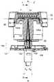
도 2a 및 도 2b 는 캡슐 홀더를 갖춘 원심분리 셀의 일 실시형태를 도시한다.
도 3a, 도 3b, 도 3c 는 본원에 따른 한 세트의 캡슐들의 일 실시형태를 도시한다.
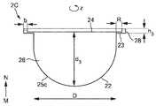
도 4 는 본원에 따른 코드 지지체의 일 실시형태를 도시한다.
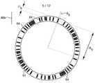
도 5 는, 특히 캡슐의 림 아래측에 배치되고 그리고 캡슐이 추출 장치의 캡슐 홀더에 끼워질 때, 캡슐에 대한 시컨스의 다른 위치를 도시한다.
도 6 은 본원에 따른 캡슐의 일 실시형태에서 기호들을 측정하는데 사용되는 광학 벤치를 도식적으로 도시한다.
도 7 은 소스 및 검출기 각도들에 따라서, 본원에 따른 캡슐의 일 실시형태의 기호들의 상대 확산 반사도의 다이어그램을 도시한다.
도 8 은 소스 및 검출기 각도들에 따라서, 본원에 따른 캡슐의 일 실시형태의 기호들간의 콘트라스트의 다이어그램을 도시한다.
도 9 는 도 4 의 캡슐의 림에서 반경방향 (R) 으로 원주방향 단면도를 따라서 광학 판독가능한 코딩된 지지체의 제 1 실시예를 도시한다.
도 10 은 도 4 의 캡슐의 림에서 반경방향 (R) 으로 원주방향 단면도를 따라서 광학 판독가능한 코딩된 지지체의 제 2 실시예를 도시한다.
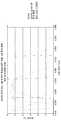
도 11 은 도 4 의 캡슐의 림에서 반경방향 (R) 으로 원주방향 단면도에서의 광학 판독가능한 코딩된 지지체의 제 3 실시예를 도시한다.
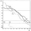
도 12 내지 도 14 는 본원에 따른 광학 판독가능한 코드 지지체들 및 다른 비교가능한 코드 지지체 각각에 대하여 반사도 (% 로) 의 측정을 그래프로 도시한다.Figure 1 shows the basic principle of centrifugal extraction.
Figures 2a and 2b show one embodiment of a centrifuge cell with a capsule holder.
Figures 3A, 3B and 3C show one embodiment of a set of capsules according to the present invention.
4 shows an embodiment of a cord support according to the present invention.
Figure 5 shows another position of the sequence for the capsule, especially when placed on the underside of the capsule and when the capsule is fitted in the capsule holder of the extraction device.
Figure 6 schematically illustrates an optical bench used to measure tones in an embodiment of the capsule according to the present invention.
Figure 7 shows a diagram of the relative diffuse reflectance of the symbols of an embodiment of the capsule according to the invention, according to the source and detector angles.
Figure 8 shows a diagram of the contrast between the symbols of an embodiment of the capsule according to the invention, according to the source and detector angles.
Figure 9 shows a first embodiment of an optically readable coded support along the circumferential section in the radial direction (R) at the rim of the capsule of Figure 4;
Figure 10 shows a second embodiment of an optically readable coded support along the circumferential section in the radial direction (R) at the rim of the capsule of Figure 4;
Figure 11 shows a third embodiment of an optically readable coded support in the circumferential section in the radial direction (R) at the rim of the capsule of Figure 4;
Figures 12-14 graphically illustrate the measurement of reflectivity (in%) for each of the optically readable code carriers and other comparable code carriers according to the present invention.
도 1 에서는, 본원의 캡슐이 사용될 수 있는 WO 2010/026053 에 개시된 바와 같이 음료 제조 시스템 (1) 의 일예를 도시한다.1 shows an example of a
원심분리 유닛 (2) 은 캡슐 내측에서 음료 성분 및 액체에 원심력들을 가하는 원심분리 셀 (3) 을 포함한다. 이 셀 (3) 은 캡슐 홀더 및 그 내부에 수용되는 캡슐을 포함할 수도 있다. 원심분리 유닛은 회전 모터 등의 구동 수단 (5) 에 연결된다. 원심분리 유닛은 집속부와 출구 (35) 를 포함한다. 수용기 (48) 는 추출된 음료를 집속하도록 출구 아래에 배치될 수 있다. 이 시스템은 물 저장기 (6) 및 유체 회로 (4) 등의 액체 공급 수단을 더 포함한다. 저장기내에 또는 유체 회로를 따라서 가열 수단 (31) 이 또한 제공될 수 있다. 액체 공급 수단은 저장기에 연결된 펌프 (7) 를 더 포함할 수 있다. 캡슐을 나오는 원심분리된 액체의 유동에 제한부를 형성하도록 유동 제한 수단 (19) 이 제공된다. 이 시스템은 셀 (3) 에 공급된 물의 유량 제어를 제공하기 위한 유동 계량 터빈 (8) 등의 유량계를 더 포함할 수 있다. 카운터 (11) 가 유동 계량 터빈 (8) 에 연결되어 발생된 임펄스 데이터 (10) 의 분석을 가능하게 할 수 있다. 그 후, 분석된 데이터는 처리기 (12) 로 전달된다. 그에 따라, 유체 회로 (4) 내의 액체의 정확한 실제 유량이 실시간으로 산출될 수 있다. 제어 유닛 (9) 에 전달되는 정보를 사용자가 입력하도록 사용자 인터페이스 (13) 가 제공될 수 있다. 이 시스템의 다른 특징들은 WO 2010/026053 에서 알 수 있다.The centrifuge unit (2) includes centrifugal cells (3) for applying centrifugal forces to beverage ingredients and liquids inside the capsules. The
도 3a, 도 3b, 및 도 3c 는 한 세트의 캡슐들 (2A, 2B, 2C) 의 일 실시형태에 관한 것이다. 캡슐들은 본체 (22), 림 (23) 및 상부 벽 부재, 각각 리드 (24) 를 포함하는 것이 바람직하다. 리드 (24) 는 천공가능한 멤브레인 또는 구멍 벽일 수 있다. 그럼으로써, 리드 (24) 및 본체 (22) 는 인클로저, 각각 성분들 격실 (26) 을 둘러싼다. 도면들에 도시된 바와 같이, 리드 (24) 는 바람직하게는 1 ~ 5 ㎜ 의 림 (23) 의 내부 환형부 (R) 에 연결되는 것이 바람직하다.Figures 3A, 3B and 3C relate to one embodiment of a set of
림은 도시된 바와 같이 반드시 수평인 것은 아니다. 이는 약간 굽혀질 수도 있다. 캡슐들의 림 (23) 은, 바람직하게는 캡슐의 회전축 (Z) 에 대하여 본질적으로 수직한 방향으로 외부로 (도시된 바와 같이) 또는 약간 경사져서 (전술한 바와 같이 굽혀진다면) 연장된다. 그럼으로써, 회전축 (Z) 은 브루잉 장치에서 캡슐의 원심분리 동안 회전축을 나타내고, 특히 브루잉 장치에서 캡슐의 원심분리 동안 캡슐 홀더 (32) 의 회전축 (Z) 과 현저하게 동일하다.The rim is not necessarily horizontal as shown. This may be slightly bent. The
도시된 실시형태는 단지 예시적인 실시형태이고 그리고 캡슐들, 특히 캡슐 본체 (22) 가 다양한 상이한 실시형태들을 취할 수 있음을 이해해야 한다.It should be understood that the illustrated embodiments are merely exemplary embodiments and that the capsules, particularly the
캡슐 각각의 본체 (22) 는 가변 깊이 (각각, d1, d2, d3) 의 단일의 볼록부 (25a, 25b, 25c) 를 가진다. 그리하여, 이 볼록부 (25a, 25b, 25c) 는 또한 절두원뿔형부 또는 부분적으로 원통형부일 수도 있다.Each
따라서, 캡슐들 (2A, 2B, 2C) 은 바람직하게는 상이한 체적들을 포함하지만, 바람직하게는 동일한 삽입 직경 (D) 을 가진다. 도 3a 의 캡슐에서는 작은 체적의 캡슐 (2A) 을 도시하는 반면, 도 3b 및 도 3c 의 캡슐에서는 큰 체적의 캡슐 (2B, 2C) 각각을 도시한다. 삽입 직경 (D) 은 여기에서 림 (23) 의 하부면과 본체 (22) 의 상부 사이의 교차 라인에서 결정된다. 하지만, 이 직경은 장치에서 캡슐의 다른 참조 직경일 수 있다.Thus, the
작은 체적의 캡슐 (2A) 은 큰 체적의 캡슐들 (2B, 2C) 을 위한 양보다 적은 양의 추출 성분, 예를 들어 분쇄 커피를 포함하는 것이 바람직하다. 따라서, 작은 캡슐 (2A) 은 분쇄 커피의 양이 4 ~ 8 그램 포함되는 10 ㎖ ~ 60 ㎖ 의 숏 커피를 전달하도록 의도된다. 큰 캡슐 (2B) 은 미디움 크기의 커피, 예를 들어 60 ~ 120 ㎖ 를 전달하도록 의도되고, 가장 큰 캡슐은 롱 크기의 커피, 예를 들어 120 ㎖ ~ 500 ㎖ 를 전달하도록 의도된다. 더욱이, 미디움 크기의 커피 캡슐 (2B) 은 6 ~ 15 그램의 분쇄 커피의 양을 포함할 수 있고, 롱 크기의 커피 캡슐 (2C) 은 8 ~ 30 그램의 분쇄 커피의 양을 포함할 수 있다.It is preferred that the
추가로, 본원에 따른 세트에서 캡슐들은, 상이한 로스팅 및/또는 분쇄 특성들을 가지고 그리고/또는 상이한 생산지의 로스팅 또는 분쇄 커피 또는 커피들의 상이한 블렌드들을 포함할 수 있다.In addition, the capsules in the set according to the invention may comprise different blends of roasted or ground coffee or coffee with different roasting and / or grinding properties and / or different production sites.
캡슐은 축 (Z) 둘레를 회전하도록 구성된다. 이 축 (Z) 은 디스크 형태를 가진 리드의 중심을 수직하게 교차한다. 축 (Z) 은 본체의 바닥 중심에서 나온다. 이 축 (Z) 은, 축 (Z) 을 기준축으로 가지고 그리고 캡슐에 위치된 원형 경로인 "원주방향" 의 개념을 규정하는데 도움을 준다. 이 원주방향은 리드, 예를 들어 리드 또는 플랜지형 림 등의 본체부상에 있을 수 있다. 리드는 장치에 삽입되기 전에는 액체 불투과성일 수 있거나 또는 리드의 중심 및/또는 주변에 제공된 작은 개구들 또는 포어들에 의해 액체 투과성일 수 있다.The capsule is configured to rotate about the axis Z. This axis (Z) intersects the center of the lead with the disk shape vertically. The axis Z originates from the bottom center of the body. This axis Z helps to define the concept of "circumferential", which is a circular path with the axis Z as the reference axis and located in the capsule. This circumferential direction may be on the body of a lead, for example a lead or a flanged rim. The leads may be liquid impermeable before being inserted into the device or may be liquid permeable by small openings or pores provided at and / or around the center of the leads.
이후, 림 (23) 의 하부면은 본체와 리드에 의해 형성된 엔클로저 외측에 위치된 림 (23) 의 일부라고 하고, 본체를 볼 수 있는 측에 캡슐이 배향되면 볼 수 있다.The lower surface of the
캡슐 또는 세트 캡슐들의 다른 특징들은 WO 2011/0069830, WO 2010/0066705, 또는 WO 2011/0092301 에서 알 수 있다.Other features of capsules or set capsules can be found in WO 2011/0069830, WO 2010/0066705, or WO 2011/0092301.
캡슐 홀더 (32) 를 가진 원심분리 셀 (3) 의 일 실시형태는 도 2a 및 도 2b 에 도시되어 있다. 캡슐 홀더 (32) 는, 캡슐을 삽입하기 위한 상부 개구와 수용기를 폐쇄하는 하부 바닥이 제공된 일반적으로 원통형 또는 원뿔형 와이드 형상의 공동을 형성한다. 이 개구는 캡슐의 본체 (22) 중 하나보다 약간 더 큰 직경을 갖는다. 개구의 윤곽은, 캡슐이 삽입되면 개구의 에지에 기대도록 구성된 캡슐의 림 (23) 의 윤곽에 끼워진다. 그 결과, 캡슐의 림 (23) 은 캡슐 홀더 (32) 의 수용부 (34) 에 적어도 부분적으로 놓인다. 하부 바닥에는 이 바닥의 외부면의 중심에 수직하게 부착된 원통형 샤프트 (33) 가 제공된다. 캡슐 홀더 (32) 는 샤프트 (33) 의 중심축 (Z) 둘레에서 회전한다.One embodiment of the
광학 판독 배열체 (100) 는 또한 도 2a 및 도 2b 에 도시되어 있다. 광학 판독 배열체 (100) 는 캡슐 홀더 (32) 의 수용부 (34) 에 기대는 캡슐의 림 (23) 의 하부면의 표면의 반사도의 레벨에 관한 정보를 포함하는 출력 신호를 전달하도록 구성된다. 광학 판독 배열체는 캡슐 홀더 (32) 를 통하여, 보다 특히 원통형 또는 원뿔형 와이드 형상의 캡슐 홀더 (32) 의 측벽을 통하여 림 (23) 의 하부면의 표면의 광학 측정을 실시하도록 구성된다. 대안으로서, 출력 신호는 상이한 정보, 예를 들어 시간에 따른 반사도의 차이, 또는 콘트라스트 정보를 포함할 수 있다. 출력 신호는 아날로그, 예를 들어 시간에 따라서 측정된 정보에 의해 변하는 전압 신호일 수 있다. 출력 신호는 디지털, 예를 들어 시간에 따라서 측정된 정보의 수치적 데이터를 포함하는 이진 신호일 수 있다.The
도 2a 및 도 2b 의 실시형태에 있어서, 판독 배열체 (100) 는 소스 광 빔 (105a) 을 방출하는 발광기 (103) 및 반사 광 빔 (105b) 을 수신하는 광수신기 (102) 를 포함한다.2A and 2B,
통상적으로, 발광기 (103) 는 적외선 광, 보다 자세하게는 850 ㎚ 의 파장을 가진 광을 방출하는 레이저 다이오드 또는 발광 다이오드이다. 통상, 광수신기 (103) 는 수신된 광 빔을 전류 또는 전압 신호로 변환시키도록 되어 있는 광다이오드이다.Typically, the
판독 배열체 (100) 는, 또한 처리기, 센서 신호 증폭기, 신호 필터들 및 처리 수단 (106) 을 발광기 (103), 광수신기 (102) 및 머신의 제어 유닛 (9) 에 결합하기 위한 회로가 내장된 인쇄 회로 기판을 구비하는 처리 수단 (106) 을 포함한다.The
발광기 (103), 광수신기 (102), 및 처리 수단 (106) 은 머신 프레임에 비교적 단단히 고정된 지지체 (101) 에 의해 고정 위치에 유지된다. 판독 배열체 (100) 는 추출 공정 동안 제 위치에 유지되고 그리고 캡슐 홀더 (32) 와는 반대로 회전 구동되지 않는다.The
특히, 발광기 (103) 는, 소스 광 빔 (105a) 이 일반적으로 고정 지점 (F) 에서 캡슐 홀더 (32) 의 수용부 (34) 를 포함하는 평면 (P) 을 교차하는 라인 (L) 을 따라서 배향되도록 배치되고, 상기 평면 (P) 은 지점 (F) 을 통과하는 법선 (N) 을 가진다. 고정 지점 (F) 은, 소스 광 빔 (105a) 이 반사면에 부딪히도록 의도된 공간에서 절대 위치를 결정하고: 캡슐 홀더가 회전되면 고정 지점 (F) 의 위치는 변하지 않게 된다. 판독 배열체는, 예를 들어 구멍들, 렌즈들 및/또는 프리즘들을 사용하는 촛점 수단 (104) 을 포함하여, 소스 광 빔 (105) 이 캡슐 홀더 (32) 에 위치된 캡슐의 리드의 하부면의 고정 지점 (F) 으로 보다 효과적으로 수렴되도록 할 수 있다. 특히, 소스 광 빔 (105) 은, 고정 지점 (F) 에 현저하게 중심맞춰지고 그리고 직경 (d) 을 가진 디스크를 조사하도록 촛점맞춰질 수 있다.In particular, the
판독 배열체 (100) 는, 라인 (L) 과 법선 (N) 사이의 각도 (θE) 가 2°~ 10°, 특히 도 2a 에 도시된 바와 같이 4°~ 5°가 되도록 구성된다. 그 결과, 반사면이 지점 (F) 에 배치되면, 반사 광 빔 (105b) 은 일반적으로 고정 지점 (F) 과 교차하는 라인 (L') 을 따라서 배향되고, 라인 (L') 과 법선 (N) 사이의 각도 (θR) 는 2°~ 10°, 특히 도 2a 에 도시된 바와같이 4°~ 5°이다. 광수신기 (102) 는, 일반적으로 라인 (L') 을 따라서 배향된 반사 광 빔 (105b) 을 적어도 부분적으로 집속하도록 지지체 (101) 상에 배치된다. 촛점 수단 (104) 은 또한 광수신기 (102) 에 보다 효과적으로 집중하는 반사 광 빔 (105b) 을 형성하도록 배열될 수도 있다. 도 2a, 도 2b 에 도시된 실시형태에 있어서, 지점 (F), 라인 (L) 및 라인 (L') 은 공면이다. 다른 실시형태에 있어서, 지점 (F), 라인 (L) 및 라인 (L') 은 공면이 아니고: 예를 들어, 지점 (F) 과 라인 (F) 을 통과하는 평면 및 지점 (F) 과 라인 (L') 을 통과하는 평면은 현저하게 90°의 각도에 위치되고, 이는 직접 반사를 없애고 그리고 적은 소음의 보다 강한 판독 시스템을 가능하게 한다.The
캡슐 홀더 (32) 는 라인 (L) 을 따라서 지점 (F) 까지 소스 광 빔 (105a) 의 부분적인 전송을 허용하도록 되어 있다. 예를 들어, 캡슐 홀더의 원통형 또는 원뿔형 와이드 형상의 공동을 형성하는 측벽은 적외선에 대하여 투명하도록 구성된다. 상기 측벽은, 적외선이 유입되도록 하는 유입면을 가지고 적외선에 대하여 반투명한 플라스틱계 재료로 제조될 수 있다.The
그 결과, 캡슐이 캡슐 홀더 (32) 에 위치되면, 광 빔 (105a) 은, 반사 광 빔 (105b) 을 형성하기 전에, 지점 (F) 에서 상기 캡슐의 림의 바닥부에 부딪힌다. 이러한 실시형태에 있어서, 반사 광 빔 (105b) 은 캡슐 홀더의 벽을 통하여 광수신기 (102) 까지 통과한다.As a result, when the capsule is placed in the
지점 (F) 에서 소스 광 빔 (105) 에 의해 조사된, 캡슐 홀더 (32) 에 위치된 캡슐의 림 (23) 의 하부면의 일부는, 캡슐 홀더 (34) 가 회전 구동될 때에만 시간에 따라서 변한다. 그리하여, 소스 광 빔 (105) 이 림의 하부면의 전체 환형부를 조사하기 위해서는 캡슐 홀더 (32) 의 완전한 공전이 필요하다.A portion of the lower surface of the
시간에 따라 반사 광 빔의 강도를 측정함으로써, 가능하다면, 소스 광 빔의 강도에 대하여 그 강도를 비교함으로써, 출력 신호가 산출 또는 발생될 수 있다. 출력 신호는 반사 광 빔의 강도의 시간에 따른 변화를 결정함으로써 산출 또는 발생될 수도 있다.By measuring the intensity of the reflected light beam over time, if possible, the output signal can be calculated or generated by comparing its intensity against the intensity of the source light beam. The output signal may be calculated or generated by determining a change over time of the intensity of the reflected light beam.
본원에 따른 캡슐은 적어도 하나의 광학 판독가능한 코드 지지체를 포함한다. 코드 지지체는, 플랜지형 림의 현재 부분 (present part) 에 있을 수 있다. 광학 코드 지지체에 기호들이 나타내어진다. 이 기호들은 적어도 하나의 시컨스로 배열되고, 이 시컨스는 캡슐과 관련된 한 세트의 정보를 코딩한다. 통상적으로, 기호 각각은 특정 이진값에 대응하고: 제 1 기호는 '0' 의 이진값을 나타낼 수 있는 반면, 제 2 기호는 '1' 의 이진값을 나타낼 수 있다.The capsule according to the present invention comprises at least one optically readable code support. The cord support may be in a present part of the flanged rim. Symbols are shown on the optical code support. These symbols are arranged in at least one sequence, which codes a set of information associated with the capsule. Typically, each of the symbols corresponds to a particular binary value: the first symbol may represent a binary value of '0', while the second symbol may represent a binary value of '1'.
특히, 상기 시컨스들의 적어도 하나의 정보 세트는 캡슐과 관련된 유형 및/또는 이하의 리스트의 아이템들 중 하나 또는 이의 조합을 인식하는 정보를 포함할 수도 있다:In particular, the at least one information set of the sequences may comprise information identifying a type associated with the capsule and / or one or a combination of the following items of the list:
● 캡슐로 음료를 제조하기 위한 파라미터들과 관련된 정보, 예를 들어 최적의 회전 속도들, 캡슐에 유입하는 물의 온도들, 캡슐 외부의 음료 집속기의 온도들, 캡슐에 유입하는 물의 유량들, 제조 공정 동안의 작동 시컨스 등;Information relating to parameters for making beverage in capsule, e.g., optimal rotational speeds, temperatures of water entering the capsule, temperatures of beverage containers outside the capsule, flow rates of water entering the capsule, Operating sequence during the process;
● 캡슐로 음료를 제조하기 위한 파라미터들을 국부적으로 및/또는 원격으로 회수하기 위한 정보, 예를 들어 캡슐에 대하여 유형을 인식하도록 해주는 식별기;- an identifier for allowing the capsule to recognize the type, for example, information for locally and / or remotely retrieving the parameters for producing the beverage;
● 캡슐의 제조와 관련된 정보, 예를 들어 제조 배치 식별기, 제조 일자, 소모 권장일, 만료일 등;● information relating to the manufacture of the capsule, eg manufacturing batch identifier, date of manufacture, recommended consumption date, expiration date, etc.;
● 캡슐의 제조와 관련된 정보를 국부적으로 및/또는 원격으로 회수하기 위한 정보.Information for the local and / or remote retrieval of information relating to the manufacture of capsules.
시컨스의 적어도 하나의 정보 세트 각각은 불필요한 정보를 포함할 수도 있다. 그리하여, 에러-점검은 비교에 의해 수행될 수 있다. 또한 이러한 방식으로, 시컨스의 몇몇 부분들이 판독불가능하더라도, 시컨스의 성공적인 판독 가능성을 향상시킨다. 시컨스의 적어도 하나의 정보 세트는 또한 에러들을 검출하고 그리고/또는 상기 정보 세트에서 에러들을 수정하기 위한 정보를 포함할 수도 있다. 에러들을 검출하는 정보는 반복 코드들, 패리티 비트 (parity bits), 검사합계 (checksums), 주기적인 중복 검사들, 암호화된 하시 (hash) 기능 데이터 등을 포함할 수 있다. 에러들을 수정하기 위한 정보는 에러-수정 코드들, 전방 에러 수정 코드들, 및 특히 컴볼류션 (convolutional) 코드들 또는 블록 코드들을 포함할 수도 있다.Each of the at least one information set of the sequence may include unnecessary information. Thus, the error-checking can be performed by comparison. Also in this way, even if some portions of the sequence are unreadable, it improves the readability of the sequence successfully. The at least one information set of the sequence may also include information for detecting errors and / or correcting errors in the information set. The information for detecting errors may include repetition codes, parity bits, checksums, periodic redundancy checks, encrypted hash function data, and the like. The information for correcting errors may include error-correcting codes, forward error correcting codes, and in particular convolutional codes or block codes.
시컨스들에 배열된 기호들은 캡슐과 관련된 정보 세트를 운반하는 데이터를 나타내는데 사용된다. 예를 들어, 시컨스 각각은 비트들의 정수를 나타낼 수 있다. 기호 각각은 하나 또는 여러 개의 이진 비트들을 인코딩할 수 있다. 데이터는 또한 기호들간의 전환 (transitions) 으로 나타내어질 수 있다. 기호들은 변조 스키마 (scheme), 예를 들어 Manchester 코드 등의 라인 코딩 스키마를 사용하여 시컨스로 배열될 수 있다.The symbols arranged in the sequences are used to represent data carrying the set of information associated with the capsule. For example, each of the sequences may represent an integer number of bits. Each symbol can encode one or several binary bits. The data can also be represented by transitions between symbols. The symbols may be arranged in a sequence using a line coding scheme such as a modulation scheme, e.g. Manchester code.
기호 각각은 인쇄 및/또는 엠보싱될 수 있다. 기호 각각은 주어진 요철을 갖도록 코드 지지체를 처리함으로써 얻어질 수도 있다. 기호들의 형상은 이하의 불완전한 리스트: 아치 형상의 세그먼트들, 개별적으로 직선이지만 섹션의 적어도 일부를 따라서 연장되는 세그먼트들, 도트들, 다각형들, 기하학적 형상들 중에서 선택될 수 있다.Each of the symbols may be printed and / or embossed. Each of the symbols may be obtained by treating the cord support to have a given unevenness. The shape of the symbols may be selected from the following incomplete list: segments of arch shape, segments that are individually straight but extend along at least a portion of the section, dots, polygons, geometric shapes.
일 실시형태에 있어서, 기호들 각각의 시컨스는 동일한 고정 길이를 가지고, 보다 자세하게는 일정한 수의 기호들을 가진다. 시컨스의 구조 및/또는 패턴은 공지되어 있고, 판독 배열체에 의해 각각의 시컨스를 인식하는 것이 용이할 수 있다.In one embodiment, the sequence of each of the symbols has the same fixed length, and more specifically a certain number of symbols. The structure and / or pattern of a sequence is known, and it may be easy to recognize each sequence by a readout arrangement.
일 실시형태에 있어서, 각각의 시컨스의 일부에서 시작 위치 및/또는 정지 위치를 결정하도록, 적어도 하나의 프리앰블 기호 (preamble symbol) 는 일부분으로 나타내어진다. 프리앰블 기호는 다른 기호들과는 별개로 식별되도록 선택된다. 다른 기호들과 비교하여 상이한 형상 및/또는 상이한 물리적 특징들을 가질 수 있다. 2 개의 인접한 시컨스들은, 일방의 시컨스의 정지 및 타방의 시컨스의 시작을 나타내는, 공통의 프리앰블 기호를 가질 수 있다.In one embodiment, at least one preamble symbol is represented in part to determine a start position and / or a stop position in a portion of each sequence. The preamble symbol is selected to be distinguished from other symbols. And may have different shapes and / or different physical characteristics compared to other symbols. Two adjacent sequences may have a common preamble symbol indicating the stop of one sequence and the start of the other sequence.
일 실시형태에 있어서, 시컨스들의 적어도 하나는, 캡슐과 관련된 정보 세트를 코딩하는 상기 시컨스에서 기호들의 위치를 결정할 수 있도록, 프리앰블 시컨스를 규정하는 기호들을 포함한다. 프리앰블을 규정하는 기호들은 공지된 예약된 비트 시컨스, 예를 들어 '10101010' 을 코딩할 수 있다.In one embodiment, at least one of the shifts includes symbols that define a preamble sequence so that the position of the symbols in the sequence that codes the information set associated with the capsule can be determined. The symbols defining the preamble may code a known reserved bit sequence, e.g., '10101010'.
일 실시형태에 있어서, 프리앰블 기호들 및/또는 프리앰블 시컨스들은 정보 세트, 예를 들어 하시 코드 또는 암호화된 시그너쳐를 비준하는 정보를 포함한다.In one embodiment, preamble symbols and / or preamble sequences include information that validates an information set, e.g., a hash code or an encrypted signature.
기호들은 환형 지지체의 원주부의 적어도 1/8, 바람직하게는 환형 지지체의 전체 원주부에 현저하게 분포된다. 이 코드는 연속적인 아치형 세그먼트들을 포함할 수 있다. 기호들은 또한 개별적으로 수직이지만 원주부의 적어도 일부를 따라서 연장되는 연속 세그먼트들을 포함할 수 있다.The symbols are significantly distributed in at least 1/8 of the circumference of the annular support, preferably in the entire circumference of the annular support. This code may contain contiguous arcuate segments. The symbols may also include continuous segments that are individually vertical but extend along at least a portion of the circumference.
시컨스는 신뢰가능한 판독을 보장하도록 원주부를 따라서 반복되는 것이 바람직하다. 시컨스는 원주부에서 적어도 2 번 반복된다. 바람직하게는, 시컨스는 원주부에서 3 번 ~ 6 번 반복된다. 시컨스의 반복은, 동일한 시컨스가 복제되고 그리고 연속 시컨스들이 원주를 따라서 일렬로 위치되어 캡슐의 360 도 회전시 동일한 시컨스가 1 번 이상 검출 또는 판독될 수 있음을 의미한다.The sequence is preferably repeated along the circumference to ensure reliable readout. The sequence is repeated at least twice in the circumference. Preferably, the sequence is repeated three to six times in the circumference. The repetition of a sequence means that the same sequence is replicated and the sequential sequences are placed in line along the circumference so that the same sequence can be detected or read at least once during a 360 degree rotation of the capsule.
도 4 를 참조하면, 코드 지지체의 일 실시형태 (30a) 가 도시되어 있다. 코드 지지체 (60a) 는 캡슐의 림 (23) 의 규정된 폭을 점유한다. 캡슐의 림 (23) 은, 지지체 (60a) 를 형성하는 내부 환형부 및 외부 (코딩되지 않은) 컬링부를 본질적으로 포함할 수 있다. 하지만, 특히 림의 하부면이 실질적으로 평평하게 형성될 수 있다면, 림의 전체 폭은 지지체 (60a) 에 의해 점유될 수 있다. 이 위치는 특히 유리한데, 이 위치는 배치될 기호들에 대하여 큰 면적을 제공하고 그리고 처리 모듈, 특히 피라미드 플레이트에 의해 유발되는 손상들을 덜 받기 쉽고 그리고 성분 투사 (projections) 를 덜 받기 쉽기 때문이다. 그 결과, 코딩된 정보의 양 및 판독물의 신뢰성 둘 다가 개선된다. 이 실시형태에 있어서, 코드 지지체 (60a) 는 160 개의 기호들을 포함하고, 기호 각각은 1 비트의 정보를 코딩한다. 기호들은 인접 (contiguous) 하고, 기호 각각은 2.25°의 원호 선 길이를 가진다.Referring to Figure 4, an embodiment 30a of a cord support is shown. The
도 5 를 참조하면, 코드 지지체의 일 실시형태 (60b) 가 평면도에 도시되어 있다. 코드 지지체 (60b) 는 캡슐과 관련되거나 또는 캡슐의 일부가 되어, 원심분리 유닛 (2) 에 의해 캡슐이 축 (Z) 둘레를 회전하면 회전 구동된다. 캡슐의 수용부는 캡슐의 림 (23) 의 하부면이다. 도 5 에 도시된 바와 같이, 코드 지지체는 기호들의 적어도 하나의 시컨스가 표시된 원주부를 가진 링일 수 있고, 그리하여 사용자는 음료 머신의 브루잉 유닛에 캡슐을 도입하기 전에 이 캡슐의 원주에 이를 위치시킬 수 있다. 그 결과, 정보를 추가하도록 이러한 지지체를 장착함으로써, 이 정보를 저장하는 수단을 내장하지 않은 캡슐이 변경될 수 있다. 지지체가 별개부이면, 추가의 고정 수단 없이 캡슐에 간단히 추가될 수 있고, 사용자는 지지체가 브루잉 유닛에 유입할 때 정확하게 위치되거나 또는 장착되자마자 지지체의 형태들 및 치수들이 캡슐에 대하여 지지체가 상대 이동하지 못함을 보장한다. 코드 지지체 (60b) 는 또한 캡슐의 수용부에 상기 요소를 단단히 고정시키는 추가의 고정 수단, 예를 들어 글루 또는 기계적 수단을 포함하여, 장착되자마자 캡슐에 대하여 지지체를 고정 유지시키는데 도움을 준다. 또한 전술한 바와 같이, 코드 지지체 (60b) 는 또한 캡슐의 구조물에 일체화되는 것처럼 림 자체의 일부일 수도 있다.Referring to Figure 5, an
기호 각각은, 캡슐이 캡슐 홀더에 위치될 때 그리고 상기 기호가 지점 (F) 에서 소스 광 빔 (105a) 에 정렬될 때 판독 배열체 (100) 에 의해 측정되도록 되어 있다. 보다 자세하게는, 각각의 상이한 기호는 상기 기호의 값에 따라 변하는 소스 광 빔 (105a) 의 반사도 레벨을 나타낸다. 기호 각각은 소스 광 빔 (105a) 의 상이한 반사 특성들 및/또는 흡수 특성들을 가진다.Each symbol is adapted to be measured by the
판독 배열체 (100) 는 코드 지지체의 조사된 부분의 특성들만을 측정하도록 되어 있기 때문에, 소스 광 빔이 코드에 포함된 모든 기호들을 조사할 때까지, 캡슐은 구동 수단에 의해 회전되어야 한다. 통상적으로, 코드를 판독하는 속도는 0.1 ~ 2000 rpm 일 수 있다.Since the
본원의 코드 지지체의 반사 특성들은 규정된 실험실 조건들에서 결정된다. 특히, 판독 배열체 (100) 에 의해 신뢰가능하게 판독되기에 적합한 캡슐의 일 실시형태의 제 1 기호 및 제 2 기호는 도 6 에 도시된 광학 벤치를 사용하여 독립적으로 측정되었다. 캡슐에 대한 상기 기호들의 확산 반사의 고니오미터 측정이 도 7 (기호 각각의 반사 강도) 및 도 8 (기호들간의 콘트라스트) 에 도시되어 있다.The reflection properties of the present cord supports are determined in defined laboratory conditions. In particular, the first and second preferences of an embodiment of a capsule suitable for being reliably read by
이하, 제 1 기호는 제 2 기호보다 더 반사적이다. 기호 각각의 확산 반사된 상대 강도의 측정을 위한 설정은, 광 소스의 각도 (θ) 및 광 검출기의 각도 (θ') 를 독립적으로 변경할 수 있도록 형성된다. 검출기는 구동식 검출기 암에 고정된 매우 미세한 기계적 팁에 접착된 전력 계량기에 연결된 광학 나섬유 (bare optical fiber) 이다. 모든 측정들에 대해서, 소스와 검출기 평면 사이의 각도 (φ) 는 φ=90°와 동일하다. 광 소스는 파장 λ=830 ㎚ 를 가진 광을 방출하는 레이저 다이오드이다.Hereinafter, the first symbol is more reflexive than the second symbol. The setting for measuring the diffuse reflected relative intensity of each symbol is formed so that the angle of the light source and the angle of the light detector can be changed independently. The detector is a bare optical fiber connected to a power meter attached to a very fine mechanical tip fixed to a powered detector arm. For all measurements, the angle (?) Between the source and detector plane is equal to? = 90 °. The light source is a laser diode that emits light having a wavelength? = 830 nm.
도 7 의 다이어그램에서는 검출기 각도 (θ') (축 200) 에 따라서 캡슐의 기호들의 상대 확산 반사도 (축 210) 를 도시한다. 검출기 각도를 0°로 설정하고 그리고 소스 각도를 5°로 설정하여, 제 1 기호에 대하여 반사도의 기준 강도 (EREF) 가 측정된다. 기호 각각의 상대 확산 반사도는 기준 강도 (EREF) 에 대하여 상대적으로 산출된다. 곡선들 (220a, 230a, 240a) 은 3 개의 상이한 소스 각도들 θ=0°, 5°, 10°에서 제 1 기호의 상대 확산 반사도를 각각 도시한다. 곡선들 (220b, 230b, 240b) 은 3 개의 상이한 소스 각도들 θ=0°, 5°, 10°에서 제 2 기호의 상대 확산 반사도를 각각 도시한다.The diagram of Figure 7 shows the relative diffuse reflectance (axis 210) of the symbols of the capsule along the detector angle [theta] '(axis 200). The reference intensity (EREF ) of reflectivity is measured for the first symbol, with the detector angle set to 0 ° and the source angle set to 5 °. The relative diffuse reflectance of each of the symbols is calculated relative to the reference intensity (EREF ). The
상대 확산 반사도는, 3°~ 6°의 검출기 각도 (θ') 의 어떠한 값에 대해서 그리고 0°~ 10°의 소스 각도 (θ) 의 어떠한 값에 대해서, 기준 강도 (EREF) 의 적어도 60% 를 나타낸다. 특히, 상대 확산 반사도는, 2.5°~ 4.4°의 검출기 각도 (θ') 의 어떠한 값에 대해서 그리고 0°~ 10°의 소스 각도 (θ) 의 어떠한 값에 대해서, 기준 강도 (EREF) 의 적어도 72% 를 나타낸다.The relative diffuse reflectance is at least 60% of the reference intensity EREF for any value of the detector angle? 'From 3 ° to 6 ° and for any value of the source angle? . In particular, the relative diffuse reflectance is at least equal to the reference intensity EREF for any value of the detector angle? 'From 2.5 ° to 4.4 ° and for any value of the source angle? 72%.
도 8 의 다이어그램에서는 검출기 각도 (θ') (축 300) 에 따라서 제 1 기호 및 제 2 기호 사이의 광학 콘트라스트 (축 310) 를 도시한다. 광학 콘트라스트는 다음의 수학식,The diagram of Figure 8 shows the optical contrast (axis 310) between the first and second symbols according to the detector angle [theta] '(axis 300). The optical contrast is calculated by the following equation:

으로 규정되고, 여기에서, i1, i2 는 각도들 (θ, θ') 의 동일한 소정의 형상에서 검출기로의 제 1 기호, 제 2 기호 각각에 의해 반사된 강도를 각각 나타낸다. 곡선들 (320, 330, 340, 350) 은 4 개의 상이한 소스 각도들 θ=0°, 5°, 10°, 15°에서 각각 상기 광학 콘트라스트를 나타낸다. 최하 콘트라스트값은, 어떠한 경우에 65% 보다 크고, 이는 신뢰가능한 신호 처리를 가능하게 한다. 특히, 광학 콘트라스트는, 2.5°~ 4.4°의 검출기 각도 (θ') 의 어떠한 값에 대해서 그리고 10°~ 15°의 소스 각도 (θ) 의 어떠한 값에 대해서, 80% 보다 크다. 특히, 광학 콘트라스트는, 6°초과의 검출기 각도 (θ') 의 어떠한 값에 대해서 그리고 0°~ 15°의 소스 각도 (θ) 의 어떠한 값에 대해서, 75% 보다 크다., Where i1 and i2 represent the intensity reflected by each of the first and second symbols to the detector in the same predetermined shape of the angles [theta] and [theta] ', respectively. The
도 9 에서는 도 4 의 원주방향 단면도에서 본원의 광학 판독가능한 코드 지지체 (30) 의 바람직한 모드를 도시한다. 코드 지지체 (30) 는 판독가능한 (외부) 측 A 및 판독불가능한 (내부) 측 B 를 포함한다. 판독가능한 측 A 에서, 지지체는 연속적인 광 반사면들 (400 ~ 403) 및 광 흡수면들 (410 ~ 414) 을 포함한다. 광 흡수면들 (410 ~ 414) 은, 여러 개의 중첩된 층들을 포함하는 베이스 구조물 (500) 에 의해 형성되는 반면, 광 흡수면들 (400 ~ 403) 은 국부적인 원주방향 영역에서 베이스 구조물에 이 베이스 구조물에 도포되는 광흡수 재료의 불연속 개별부들, 바람직하게는 잉크 층들 (528) 의 개별부들을 오버레이함으로써 형성된다. 베이스 구조물은 금속 (510), 바람직하게는 알루미늄 (또는 알루미늄 합금) 의 바람직한 일체식 층을 포함하고, 이 층에는 바람직하게는 이소시아네이트 또는 폴리에스테르로 제조되는 투명 중합 프라이머 (515) 가 피복된다. 금속, 예를 들어 알루미늄 층의 두께는 캡슐의 봉입 (containment) 구조물 (예를 들어, 본체와 림) 로의 지지체의 성형성에 대한 결정 인자일 수 있다. 성형성의 이유로, 알루미늄 층은 바람직하게는 40 ~ 250 미크론, 가장 바람직하게는 50 ~ 150 미크론 포함된다. 이 범위에서, 특히 캡슐이 림에 밀봉된 가스 배리어 막을 더 포함하면, 알루미늄 두께는 또한 캡슐내의 성분의 신선도를 보존하기 위해서 가스 배리어 특성들을 제공할 수 있다.Figure 9 shows a preferred mode of the optically
코드 지지체는 캡슐의 림 (22) 및 본체 (23) 를 형성하도록 변형되는 적층체로 형성될 수 있다 (도 3a ~ 도 3b 참조). 이러한 경우에, 적층체는 베이스 구조물 (500) 의 조성을 가지고 그리고 캡슐 (예를 들어, 본체, 림) 의 성형 조작 전에 평평한 형상에서 광 흡수 잉크부들 (400 ~ 403) 로 인쇄된다. 그리하여, 잉크부들의 인쇄는 적층체의 후속 변형에 영향을 주어야 하고, 그리하여 코딩된 표면들을 정확하게 위치결정할 수 있다. 이러한 유형의 잉크는 단일-부품, 이중-부품, PVC 계 또는 PVC 프리계 잉크들일 수 있다. 흑색 잉크는 색상 (coloured) 잉크들보다 더 낮은 반사도 및 더 높은 콘트라스트를 제공함으로 바람직하다. 하지만, 흑색 잉크 부분들은 동등한 색상 잉크 부분들, 바람직하게는 어둡거나 불투명한 잉크들로 대체될 수 있다. 잉크는 색상 안료들의 예를 들어 50 ~ 80% 를 포함할 수 있다.The cord support may be formed of a laminate that is deformed to form the
바람직하게는, 금속 층은 알루미늄이고 그리고 6 ~ 250 미크론의 두께를 가진다. 프라이머는 금속 (즉, 알루미늄) 층의 조도 (rugosity) 의 레벨을 유지할 수 있다. 이는, 또한 금속 층, 특히 알루미늄에 대한 잉크들의 접착을 향상시킨다. 프라이머는 광 빔의 확산을 감소시키도록 비교적 얇게 남아 있어야 한다. 바람직하게는, 프라이머의 두께는 0.1 ~ 5 미크론, 가장 바람직하게는 0.1 ~ 3 미크론 포함된다. 프라이머의 밀도는 2 ~ 3 gsm 포함되는 것이 바람직하고, 예를 들어 약 2.5 gsm 이다.Preferably, the metal layer is aluminum and has a thickness of 6 to 250 microns. The primer can maintain a level of rugosity of the metal (i.e., aluminum) layer. This also improves adhesion of the inks to the metal layer, especially aluminum. The primer should remain relatively thin to reduce diffusion of the light beam. Preferably, the thickness of the primer is 0.1 to 5 microns, most preferably 0.1 to 3 microns. The density of the primer is preferably comprised between 2 and 3 gsm, for example about 2.5 gsm.
선택적으로, 베이스 구조물은, 판독불가능한 측에 추가 층들, 바람직하게는 폴리프로필렌 또는 폴리에틸렌 등의 폴리머 층 및 이 폴리머 층 (520) 을 금속 층 (510) 에 접착시키는 접착제 층 (525) 또는 캡슐의 림에 리드 또는 막을 밀봉시킬 수 있는 히트 시일 라커 또는 내부 보호 라커 또는 바니시를 포함할 수 있다. 규정된 바와 같이 지지체는 캡슐, 예를 들어 캡슐의 플랜지형 림 및 본체의 일체부를 형성할 수 있다.Alternatively, the base structure may include additional layers on the unreadable side, preferably a polymer layer such as polypropylene or polyethylene, and an
도 9 의 모드에 따른 바람직한 베이스 구조물은, 지지체의 B 측에서부터 A 측까지: 30 미크론의 폴리프로필렌 층, 접착제, 90 미크론의 알루미늄 층, 2 미크론 및 2.5 gsm 밀도의 폴리에스테르 층 및 1 미크론의 흑색 잉크 부분들을 각각 포함한다. 다른 모드에 있어서, 프라이머 층은 5 미크론의 두께, 바람직하게는 5.5 gsm 밀도 및 5% (중량) 금속 안료들을 포함하는 라커로 대체된다. 프라이머 (515) 상에 추가의 보호 클리어 코팅이 도포되어 잉크 층들 (528) (비도시) 을 덮고 또한 보호할 수 있음을 알아야 한다.A preferred base structure according to the mode of Figure 9 comprises a polypropylene layer of 30 microns, an adhesive, an aluminum layer of 90 microns, a polyester layer of 2 microns and 2.5 gsm density, and a 1 micron black Ink portions. In another mode, the primer layer is replaced with a lacquer containing a 5 micron thick, preferably 5.5 gsm density and 5% (by weight) metal pigments. It should be noted that additional protective clear coatings may be applied on the
도 10 은 본원의 코드 지지체 (30) 의 다른 모드에 관한 것이다. 이러한 경우에, 베이스 구조물은 도 9 의 프라이머 (510) 를 대체하는 라커 (530) 를 포함한다. 라커는 알루미늄, 은 또는 구리 안료들 또는 이들의 혼합물 등의 금속 안료들 (535) 을 내장한 중합 층이다. 잉크 층들 (528) 은 라커에 도포된다. 라커의 두께는 도 9 의 프라이머 (510) 의 두께보다 다소 크고, 바람직하게는 3 ~ 8 미크론, 가장 바람직하게는 5 ~ 8 미크론 포함된다. 금속 안료들은 폴리머의 두께 증가에 의해 금속 층의 반사도 저감을 보상할 수 있도록 한다. 라커는 또한 금속 층의 조도의 레벨을 유지한다. 바람직하게는, 라커에 대한 금속 안료들의 비는 적어도 1 중량% 이고, 보다 바람직하게는 2 ~ 10 중량% 포함된다. 라커 (530) 상에 추가의 보호 클리어 코팅이 도포되어 잉크 층들 (528) (비도시) 을 덮고 또한 보호할 수 있음을 알아야 한다. 도 11 은 본원의 코드 지지체 (30) 의 다른 모드에 관한 것이다. 이러한 경우에, 베이스 구조물 (500) 은 거울면들 (610 ~ 615) 및 조화처리면들 (600 ~ 604) 을 가진 금속 및/또는 폴리머 층 (540) 을 포함한다. 거울면들 (610 ~ 615) 은 5 미크론 미만, 바람직하게는 0.2 ~ 2 미크론의 조도 (Rz) 를 제공함으로써 얻어질 수도 있다. 광흡수면들 (600 ~ 604) 은 2 미크론 초과, 보다 바람직하게는 5 미크론 초과의 조도 (Rz) 를 가진 조화처리면 부분들을 형성함으로써 얻어진다. 예를 들어, 거울면들은 금속 안료들 (545) 을 포함하는 폴리에스테르 또는 이소시아네이트 등의 중합 층 (540) 에 형성된다. 베이스 구조물의 조화처리면들은 샌딩, 쇼트 블라스팅, 밀링, 레이저 새김, 화학적 어택 및 이들의 조합 등의 어떠한 적절한 기술에 의해 얻어질 수 있다. 중합 층 (540) 에서 안료들의 비는 적어도 5 중량%, 바람직하게는 10 ~ 30 중량% 일 수 있다. 바람직하게는 알루미늄 등의 금속 층인 지지 층 (510) 이 제공될 수 있다. 층들 (510, 540) 은 단일의 금속 또는 중합 층에 의해 교체될 수 있음을 알아야 한다. 이 층 (540) 상에 추가의 보호 클리어 코팅이 도포되어 광반사면 부분 및 광흡수면 부분 (600 ~ 615) (비도시) 을 덮고 그리고 보호할 수 있음을 알아야 한다.10 relates to another mode of the
본 발명에 있어서, 특정 금속들에 대한 언급은, 금속이 주요 성분을 중량으로 나타내는 금속의 가능한 합금들을 포함하고, 예를 들어 알루미늄은 알루미늄의 합금들을 포함한다.In the present invention, references to certain metals include possible alloys of metals in which the metal represents the major components by weight, for example, aluminum comprises alloys of aluminum.
실시예들 :Examples:
통합형 코드 지지체를 포함하는 캡슐들은 신호(비트 1/비트 0) 의 반사도 레벨을 평가하도록 시험되었다. 시험들은, 캡슐 홀더 (32) 를 제거하고 그리고 캡슐의 림을 유지하고 또한 광 빔용 개방 공기 통로가 형성된 투명한 클램핑 플레이트로 대체하여, 도 2a 및 도 2b 의 장치의 간단한 형상으로 실시되었다. 슬렌더 경로 및 수신기 경로 간의 각도는 8°이고, 법선축 (N) 의 각 측에서 4°로 분배되었다.Capsules containing an integrated cord support were tested to evaluate the level of reflectivity of the signal (
실시예 1 - 착색된 라커를 가진 베이스 구조물에 의한 광반사면들 및 오버레잉 잉크부들에 의한 광흡수면들을 가진 검출가능한 코드Example 1 - Detectable codes with light absorbing surfaces by light reflecting surfaces and overlying ink parts by a base structure with a colored lacquer
지지체는 5 미크론 및 5.5 gsm 의 알루미늄 안료의 라커로 피복된 30 미크론의 알루미늄으로 형성된 반사 베이스 구조물을 포함하였다. 흡수면들은 Siegwerk 에 의해 이용가능한 1 미크론 흑색 PVC 잉크의 층으로 형성되었다. 반사면들은 베이스 구조물 (비트 1) 에 의해 제조되었고, 흡수면들 (비트 0) 은 흑색 잉크부들에 의해 제조되었다. 반사면들 (비트 1) 에 대하여 측정된 최대 반사도는 2.68% 이었다. 비트 1 에서의 스프레드 (spread) 는 1.32% 이었다. 흡수면 (비트 0) 에 대하여 측정된 최소 반사도는 0.73% 이었다. 비트 0 에서의 스프레드는 0.48% 이었다. 그 결과들은 도 12 에 그래픽으로 도시되었다.The support included a reflective base structure formed of 30 microns of aluminum coated with a 5 micron and 5.5 gsm aluminum pigment lacquer. The absorbing surfaces were formed as a layer of 1 micron black PVC ink available by Siegwerk. The reflective surfaces were fabricated by the base structure (bit 1), and the absorption surfaces (bit 0) were fabricated by black ink parts. The measured maximum reflectivity for the reflective surfaces (bit 1) was 2.68%. The spread in
실시예 2 - 무색 프라이머를 가진 베이스 구조물에 의한 광반사면들 및 오버레잉 잉크부들에 의한 광흡수면들을 가진 검출가능한 코드Example 2 - Detectable codes with light absorbing surfaces by light reflecting surfaces and overlying ink parts by a base structure with colorless primer
반사면들을 형성하는 베이스 구조물 및 흡수면들을 형성하는 잉크부들을 구비하는 광학 판독 지지체를 포함하는 비워진 캡슐에 대하여 반사도 측정을 실시하였다. 이를 위해, 베이스 구조물은 B 측에서 A (판독가능한) 측까지: 30 미크론의 폴리프로필렌 층, 접착제, 90 미크론의 알루미늄 층, 2 미크론 및 2.5 gsm (밀도) 폴리에스테르 프라이머를 각각 포함하였다. Siegwerk 에 의해 이용가능한 1 미크론의 흑색 잉크의 불연속 비트부들은 프라이머의 표면에 인쇄되었다. 지지체는 잉크 인쇄 후에 캡슐의 본체로 딥 드로잉함으로써 형성되었다. 그리하여, 반사면들은 베이스 구조물 (비트 1) 에 의해 제조되었고, 흡수면들 (비트 0) 은 흑색 잉크부들에 의해 제조되었다. 지지체의 반사도가 측정되었다. 그 결과들은 도 13 에 그래픽으로 도시되었다. 반사면들 (비트 1) 에 대하여 측정된 최대 반사도는 5.71% 이었다. 비트 1 에서의 스프레드는 1.49% 이었다. 흡수면 (비트 0) 에 대하여 측정된 최소 반사도는 0.87% 이었다. 비트 0 에서의 스프레드는 0.47% 이었다.A reflectance measurement was performed on a blanked capsule comprising an optical read support having a base structure forming reflective surfaces and ink portions forming absorbing surfaces. To this end, the base structure included a 30 micron polypropylene layer from the B side to the A (readable) side, an adhesive, an aluminum layer of 90 microns, a 2 micron and a 2.5 gsm (density) polyester primer, respectively. Discontinuous bit portions of 1 micron black ink available by Siegwerk were printed on the surface of the primer. The support was formed by deep drawing into the body of the capsule after ink printing. Thus, the reflecting surfaces were made by the base structure (bit 1), and the absorption surfaces (bit 0) by black ink parts. The reflectivity of the support was measured. The results are graphically shown in FIG. The measured maximum reflectivity for the reflective surfaces (bit 1) was 5.71%. The spread at
실시예 3 - 베이스 구조물에 의한 광흡수면들 및 오버레잉 잉크부들에 의한 광반사면들을 가진 검출불가능한 코드Example 3 - Detectable codes with light absorbing surfaces by base structure and light reflecting surfaces by overlying ink parts
흡수면들을 형성하는 베이스 구조물 및 반사면들을 형성하는 잉크부들을 구비하는 광학 판독 지지체를 포함하는 비워진 캡슐에 대하여 반사도 측정을 실시하였다. 이를 위해, 알루미늄 지지체는 5 미크론 두께의 연속 매트 흑색 라커로 덮여졌다. 반사면들은, 25 중량% 초과의 광반사 은 안료들을 함유하는 1 미크론 두께를 가진 잉크의 별개부들에 의해 제조되었다. 놀랍게도, 신호는 비트 1 과 비트 0 사이를 구분하기에 충분하지 않았다. 그 결과들은 도 14 에 그래픽으로 도시되었다. 반사면들 (비트 1) 에 대하여 측정된 최대 반사도는 0.93% 이었다. 반사면들 (비트 1) 에 대하여 측정된 최소 반사도는 0.53% 이었다. 흡수면 (비트 0) 에 대하여 측정된 최소 반사도는 0.21% 이었다. 비트 0 에 대한 스프레드는 0.23% 이었다.A reflectance measurement was performed on a blanked capsule comprising an optical read support having a base structure forming absorbing surfaces and ink portions forming reflecting surfaces. For this purpose, the aluminum support was covered with a continuous mat black lacquer with a thickness of 5 microns. Reflective surfaces were prepared by separate parts of the ink with a thickness of 1 micron thick containing pigments in excess of 25% by weight of light reflection. Surprisingly, the signal was not sufficient to distinguish between
실시예 4 - 캡슐의 원심분리에 의해 음료 제조 장치에서 음료를 전달하도록 된 캡슐의 일부이거나 또는 이와 관련되는 광학 판독가능한 코드 지지체 (30, 60a, 60b) 로서, 상기 지지체는 상기 지지체상에 나타내어진 기호들의 적어도 하나의 시컨스를 포함하여, 각각의 상기 기호는, 상기 캡슐이 회전축을 따라서 회전 구동되는 동안, 외부 판독 장치의 판독 배열체에 의해 순차적으로 판독가능하며, 상기 기호들은 광반사면들 (400 ~ 403; 610 ~ 615) 및 광흡수면들 (410 ~ 414; 600 ~ 604) 로 본질적으로 형성되고, 상기 지지체는 적어도 상기 기호들의 시컨스를 따라서 연속적으로 연장되는 베이스 구조물 (500) 및 상기 베이스 구조물의 표면에 형성되거나 또는 그에 국부적으로 도포되는 불연속적인 별개의 광흡수부들 (528; 628) 을 포함하며, 상기 불연속적인 별개의 광흡수부들은 광흡수면들을 형성하고, 상기 베이스 구조물 (500) 은 상기 별개의 광흡수부들에 의해 점유되는 표면적들 외부에 광반사면들 (400 ~ 403; 610 ~ 615) 을 형성하고, 상기 별개의 광흡수부들 (410 ~ 414; 600 ~ 604) 은 상기 별개의 광흡수부들에 의해 점유되는 표면적들 외부에 베이스 구조물 중 하나보다 더 낮은 광 반사도를 제공하도록 배열되는 것을 특징으로 한다.Example 4 - An optically readable code support (30, 60a, 60b) that is part of or associated with a capsule adapted to deliver a beverage in a beverage production apparatus by centrifugation of the capsule, said support comprising: Wherein each symbol is sequentially readable by a readout arrangement of an external readout device while the capsule is rotationally driven along an axis of rotation, said symbols comprising at least one of the light reflection surfaces 400 Wherein said support comprises a base structure (500) which extends continuously along at least a sequence of said symbols and a base structure (500) which is essentially formed of light absorbing surfaces (410 to 414; 600 to 604) Discrete discrete light absorbing portions (528; 628) formed on or applied locally to the surface of the substrate The portions form light absorbing surfaces and the
실시예 5 : 실시예 4 에 따른 광학 판독가능한 코드 지지체로서, 광반사 베이스 구조물 (500) 은 광반사면들을 제공하도록 상기 베이스 구조물에 배열된 금속을 포함한다.Example 5 : As an optically readable code support according to Example 4, a light
실시예 6 : 실시예 5 에 따른 광학 판독가능한 코드 지지체로서, 광반사 베이스 구조물은 일체식 금속 지지 층 (510) 및/또는 광반사 입자들 층 (530, 540), 바람직하게는 중합 매트릭스내의 금속 안료들을 포함한다.Example 6 : As an optically readable code support according to Example 5, the light reflective base structure comprises an integral
실시예 7 : 실시예 5 또는 실시예 6 에 따른 광학 판독가능한 코드 지지체로서, 상기 금속은 알루미늄, 은, 철, 주석, 금, 구리 및 이들의 조합물로 구성된 그룹 중에서 선택된다.Embodiment 7 : An optically readable code support according to
실시예 8 : 실시예 6 또는 실시예 7 에 따른 광학 판독가능한 코드 지지체로서, 광반사 베이스 구조물은 광반사면들 (410 ~ 414) 을 형성하도록 투명한 중합 프라이머 (515) 에 의해 피복된 일체식 금속 지지 층 (510) 또는 외부 금속 층 (예를 들어, 중합 층의 기상 금속화에 의해) 에 의해 피복된 내부 중합 층을 포함한다.Example 8 : As an optically readable code support according to Example 6 or Example 7, the light reflecting base structure comprises an integral metal support (not shown) coated by a
실시예 9 : 실시예 8 에 따른 광학 판독가능한 코드 지지체로서, 비금속성 투명한 중합 프라이머 (515) 는 5 미크론 미만, 가장 바람직하게는 0.1 ~ 3 미크론 두께를 가진다.Example 9 : As an optically readable code support according to Example 8, the non-metallic
실시예 10 : 실시예 7 에 따른 광학 판독가능한 코드 지지체로서, 광반사 베이스 구조물은 일체식 금속 지지 층 (510) 또는 중합 지지 층을 포함하고; 상기 층은 광반사 입자들, 바람직하게는 금속 안료들 (535) 을 포함하는 라커 (530) 에 의해 피복된다.Example 10 : An optically readable code support according to
실시예 11 : 실시예 10 에 따른 광학 판독가능한 코드 지지체로서, 상기 라커 (530) 는 3 미크론 초과 및 10 미크론 미만, 바람직하게는 5 ~ 8 미크론의 두께를 가진다.Example 11 : An optically readable code support according to
실시예 12 : 실시예 10 또는 실시예 11 에 따른 광학 판독가능한 코드 지지체로서, 상기 라커 (530) 는 2 ~ 10 중량% 금속 안료들 (535), 바람직하게는 약 5 중량% 안료들을 포함한다.Example 12 : An optically readable code support according to example 10 or example 11, wherein the
실시예 13 : 이전의 실시예 4 내지 실시예 12 중 어느 것에 따른 광학 판독가능한 코드 지지체로서, 상기 불연속적인 별개의 광흡수부들 (528) 은 상기 베이스 구조물 (500) 에 도포된 잉크에 의해 형성된다.Example 13 : As an optically readable code support according to any of the previous Examples 4 to 12, the discrete discrete
실시예 14 : 실시예 13 에 따른 광학 판독가능한 코드 지지체로서, 상기 잉크는 0.25 ~ 3 미크론의 두께를 가진다.Example 14 : An optically readable code support according to
실시예 15 : 실시예 13 또는 실시예 14 에 따른 광학 판독가능한 코드 지지체로서, 상기 잉크는 적어도 50 중량% 안료들, 보다 바람직하게는 약 60 중량% 포함한다.Example 15 : An optically readable code support according to example 13 or example 14, wherein said ink comprises at least 50% by weight pigments, more preferably about 60% by weight.
실시예 16 : 이전의 실시예 4 내지 실시예 15 중 어느 것에 따른 광학 판독가능한 코드 지지체로서, 상기 불연속적인 광흡수부들 (528) 은 적어도 2 미크론, 바람직하게는 2 ~ 10 미크론, 가장 바람직하게는 약 5 미크론의 조도 (Rz) 를 가진 베이스 구조물의 조화처리면들 (600 ~ 604) 을 형성한다.Example 16 : An optically readable code support according to any one of the
실시예 17 : 실시예 16 에 따른 광학 판독가능한 코드 지지체로서, 조화처리면 부분들은, 상기 베이스 구조물상에 잉크의 조화처리층을 도포함으로써 얻어지거나 또는 샌딩, 쇼트 블라스팅, 밀링, 화학적 어택, 레이저 새김, 인-몰드 성형 및 이들의 조합에 의해 상기 베이스 구조물 (500) 의 표면에 직접 형성된다.Embodiment 17 : An optically readable code support according to
실시예 18 : 이전의 실시예 4 내지 실시예 17 중 어느 것에 따른 광학 판독가능한 코드 지지체를 포함하는 캡슐이다.Example 18 : A capsule comprising an optically readable code support according to any of the previous Examples 4-17.
실시예 19 : 원심분리에 의해 음료 제조 장치에서 음료를 전달하도록 된 캡슐로서, 본체 (22), 플랜지형 림 (23), 및 이전의 실시예 4 내지 실시예 18 중 어느 것에 따른 광학 판독가능한 코드 지지체 (30, 60a, 60b) 를 포함하고, 상기 코드 지지체 (30, 60a, 60b) 는 상기 캡슐의 적어도 상기 림 (23) 의 일체부이며, 상기 캡슐의 상기 본체 (22) 와 상기 림 (23) 은, 상기 지지체 (30, 60a, 60b) 를 포함하는 평평하거나 미리형성된 구조물을 형성함으로써, 예를 들어 딥 드로잉함으로써 얻어진다.Example 19 : Capsule adapted for delivery of beverage in a beverage production apparatus by centrifugation, comprising a
Claims (15)
Translated fromKorean상기 광학 판독가능한 코드 지지체는 상기 광학 판독가능한 코드 지지체상에 나타내어진 기호들의 적어도 하나의 시컨스를 포함하여, 각각의 상기 기호는, 상기 캡슐이 회전축을 따라서 회전 구동되는 동안, 외부 판독 장치의 판독 배열체에 의해 순차적으로 판독가능하며,
상기 기호들은 광반사면 부분들 (610 ~ 615) 및 광흡수면 부분들 (600 ~ 604) 의 패턴으로 본질적으로 형성되고, 상기 광흡수면 부분들은 상기 광반사면 부분들보다 낮은 광반사 강도를 제공하고,
상기 광학 판독가능한 코드 지지체는 적어도 상기 기호들의 시컨스를 따라서 연속적으로 연장되는 적어도 하나의 베이스 층 또는 구조물 (500) 을 포함하며,
상기 광흡수면 부분들은 상기 광반사면 부분들보다 높은 조도 (rugosity; Rz) 를 가진 조화처리면 (roughened surface) 부분인, 광학 판독가능한 코드 지지체.An optically readable code support (30) that is part of or associated with a capsule adapted to deliver a beverage in a beverage production apparatus,
Wherein said optically readable code support comprises at least one sequence of symbols indicated on said optically readable code support such that each said symbol is associated with a readout arrangement of an external readout arrangement Which are sequentially readable by a sieve,
The symbols are essentially formed in a pattern of light reflecting surface portions 610 - 615 and light absorbing surface portions 600 - 604, the light absorbing surface portions providing a lower light reflection intensity than the light reflecting surface portions ,
The optically readable code support comprising at least one base layer or structure (500) extending continuously along at least a sequence of symbols,
Wherein the light absorbing surface portions are roughened surface portions having a higher rugosity (Rz) than the light reflecting surface portions.
상기 광반사면 부분들은 상기 베이스 층 또는 구조물 자체의 비조화처리 또는 거울 반사면들인, 광학 판독가능한 코드 지지체.The method according to claim 1,
Wherein the light reflecting surface portions are non-coherent treatment or mirror reflecting surfaces of the base layer or the structure itself.
상기 광흡수면들은 상기 베이스 층 또는 구조물에 일체로 형성되는, 광학 판독가능한 코드 지지체.3. The method according to claim 1 or 2,
Wherein the light absorbing surfaces are integrally formed with the base layer or structure.
상기 광흡수면들은 샌드 블라스팅, 쇼트 블라스팅, 밀링, 화학적 어택, 레이저 새김, 인-몰드 성형 및 이들의 조합 중 어느 하나에 의해 상기 베이스 층 또는 구조물에 형성되는, 광학 판독가능한 코드 지지체.The method of claim 3,
Wherein the light absorbing surfaces are formed on the base layer or structure by any of sand blasting, shot blasting, milling, chemical attack, laser engraving, in-mold molding and combinations thereof.
상기 광흡수면들은 상기 베이스 층 또는 구조물의 사출 성형에 의해 형성되는, 광학 판독가능한 코드 지지체.5. The method of claim 4,
Wherein the light absorbing surfaces are formed by injection molding of the base layer or structure.
상기 광흡수면 부분들은 상기 베이스 층 또는 구조물에 도포된 조화처리 재료의 1 이상의 층 부분들 또는 피착물에 의해 형성되는, 광학 판독가능한 코드 지지체.3. The method of claim 2,
Wherein the light absorbing surface portions are formed by one or more layer portions or adherends of the co-treatment material applied to the base layer or the structure.
상기 광반사면 부분들은 조화처리면의 베이스 층 또는 구조물상에 도포된 재료의 1 개 이상의 층 부분들 또는 피착물에 의해 형성되는, 광학 판독가능한 코드 지지체.The method according to claim 1,
Wherein the light-reflecting surface portions are formed by one or more layer portions or adherends of the material applied on the base layer or structure of the roughened surface.
상기 광흡수면들은 적어도 2 미크론, 바람직하게는 2 ~ 100 미크론, 가장 바람직하게는 약 5 ~ 10 미크론의 조도 (Rz) 를 가지는, 광학 판독가능한 코드 지지체.8. The method according to any one of claims 1 to 7,
Wherein the light absorbing surfaces have an illuminance (Rz) of at least 2 microns, preferably 2 to 100 microns, and most preferably about 5 to 10 microns.
상기 광반사면들은 2 미크론 미만의 조도를 가지는, 광학 판독가능한 코드 지지체.9. The method according to any one of claims 1 to 8,
Wherein the light reflective surfaces have an illuminance of less than 2 microns.
상기 광반사면 부분들 및 상기 광흡수면 부분들은, 최대 강도에서, 90 도 미만으로 서로 상이한, 바람직하게는 45 도 미만으로 서로 상이한 거의 동일한 반사 각도(들) 내에서 주어진 경사의 입사 광 빔이 반사 광 빔으로서 반사되도록 배열되는, 광학 판독가능한 코드 지지체.10. The method according to any one of claims 1 to 9,
The light-reflecting surface portions and the light-absorbing surface portions are arranged such that at a maximum intensity, an incident light beam of a given inclination within substantially the same reflection angle (s) that are different from each other by less than 90 degrees, preferably less than 45 degrees, And is arranged to be reflected as a light beam.
상기 광학 판독가능한 코드 지지체는 환형의 형상을 가지는, 광학 판독가능한 코드 지지체.11. The method according to any one of claims 1 to 10,
The optically readable code support having an annular shape.
상기 광반사면 부분들 (610 ~ 615) 및 상기 광흡수면 부분들 (600 ~ 604) 의 패턴은 상기 광학 판독가능한 코드 지지체의 원주부에서 전체적으로 또는 부분적으로 연장되는, 광학 판독가능한 코드 지지체.12. The method of claim 11,
Wherein the pattern of light reflective surface portions (610 - 615) and the light absorbing surface portions (600 - 604) extend in whole or in part in the circumference of the optically readable code support.
상기 사출 몰드는 바람직하게는 환형의 성형 표면을 포함하고, 상기 성형 표면은 상기 광흡수면 부분들을 성형하기 위한 일련의 별개의 조화처리면 부분들 및 일련의 별개의 거울면 부분들 또는 상기 광반사면 부분들을 성형하기 위한 조화처리면 부분들보다 낮은 조도를 가진 부분들을 포함하는, 광학 판독가능한 코드 지지체를 제조하기 위한 사출 몰드.An injection mold for producing an optically readable code support according to any one of claims 1 to 8 by injection molding of an injection moldable material such as plastic,
The injection mold preferably comprises an annular shaping surface, the shaping surface comprising a series of discrete roughened surface portions for shaping the light absorbing surface portions and a series of discrete mirror surface portions, And portions having lower illuminance than the roughened surface portions for shaping the portions. ≪ Desc / Clms Page number 21 >
Applications Claiming Priority (3)
| Application Number | Priority Date | Filing Date | Title |
|---|---|---|---|
| EP11189232 | 2011-11-15 | ||
| EP11189232.9 | 2011-11-15 | ||
| PCT/EP2012/072536WO2013072326A1 (en) | 2011-11-15 | 2012-11-14 | Optical readable code support and capsule for preparing a beverage having such code support providing an enhanced readable optical signal |
Publications (2)
| Publication Number | Publication Date |
|---|---|
| KR20140095529Atrue KR20140095529A (en) | 2014-08-01 |
| KR102095181B1 KR102095181B1 (en) | 2020-04-01 |
Family
ID=47143911
Family Applications (2)
| Application Number | Title | Priority Date | Filing Date |
|---|---|---|---|
| KR1020147014877AActiveKR102075888B1 (en) | 2011-11-15 | 2012-11-08 | Optical readable code support and capsule for preparing a beverage having such code support providing an enhanced readable optical signal |
| KR1020147014879AActiveKR102095181B1 (en) | 2011-11-15 | 2012-11-14 | Optical readable code support and capsule for preparing a beverage having such code support providing an enhanced readable optical signal |
Family Applications Before (1)
| Application Number | Title | Priority Date | Filing Date |
|---|---|---|---|
| KR1020147014877AActiveKR102075888B1 (en) | 2011-11-15 | 2012-11-08 | Optical readable code support and capsule for preparing a beverage having such code support providing an enhanced readable optical signal |
Country Status (23)
| Country | Link |
|---|---|
| US (5) | US20140295032A1 (en) |
| EP (2) | EP2779879B1 (en) |
| JP (2) | JP6208677B2 (en) |
| KR (2) | KR102075888B1 (en) |
| CN (2) | CN103930008B (en) |
| AR (1) | AR089573A1 (en) |
| AU (2) | AU2012338982B2 (en) |
| BR (2) | BR112014011486B1 (en) |
| CA (2) | CA2855711C (en) |
| DK (1) | DK2779879T3 (en) |
| ES (2) | ES2569051T3 (en) |
| HU (1) | HUE028455T2 (en) |
| IL (2) | IL231921B (en) |
| IN (2) | IN2014DN03181A (en) |
| MX (2) | MX350161B (en) |
| MY (1) | MY166493A (en) |
| PH (1) | PH12014500752A1 (en) |
| PL (1) | PL2779879T3 (en) |
| RU (2) | RU2604798C2 (en) |
| SG (1) | SG11201401538UA (en) |
| TW (1) | TWI569759B (en) |
| WO (2) | WO2013072239A1 (en) |
| ZA (1) | ZA201404388B (en) |
Families Citing this family (80)
| Publication number | Priority date | Publication date | Assignee | Title |
|---|---|---|---|---|
| US7640843B2 (en) | 2003-01-24 | 2010-01-05 | Kraft Foods R & D, Inc. | Cartridge and method for the preparation of beverages |
| US10722066B2 (en)* | 2010-12-04 | 2020-07-28 | Adrian Rivera | Windowed single serving brewing material holder |
| US10071851B2 (en) | 2010-07-12 | 2018-09-11 | Robert Bao Vu | Apparatus and products for producing beverages, and methods for making and using same |
| ES2894848T3 (en)* | 2011-11-15 | 2022-02-16 | Nestle Sa | Support and capsule for preparing a drink by centrifugation, system and method for preparing a drink by centrifugation |
| HUP1200097A2 (en)* | 2012-02-15 | 2013-08-28 | Glenisys Kft | Security element and method for checking originality of a printed matter |
| DE102013013598A1 (en)* | 2013-08-19 | 2015-02-19 | Mecoswiss Mechanische Componenten Gmbh & Co. Kg | "Hot beverage system, capsule and preparation device" |
| WO2015028528A1 (en)* | 2013-09-02 | 2015-03-05 | Koninklijke Philips N.V. | Transparent computer structure |
| EP3236819B1 (en)* | 2014-12-24 | 2020-01-29 | Société des Produits Nestlé S.A. | A beverage preparation machine |
| PT108210B (en)* | 2015-02-11 | 2020-12-30 | Novadelta - Comércio E Indústria De Cafés S.A. | FEED CARTRIDGE WITH BINARY CODE, DRINK PREPARATION MACHINE AND OPERATING PROCESS OF A MACHINE USING THE REFERRED FEED CARTRIDGE |
| TWI642395B (en)* | 2016-02-23 | 2018-12-01 | 耐斯泰克公司 | A container and a computer program executable on one or more processors of a code processing subsystem of a beverage or foodstuff preparation machine, a beverage or foodstuff preparation system and a method of preparing a beverage or foodstuff using the |
| FR3053231B1 (en)* | 2016-06-30 | 2019-05-24 | Compagnie Mediterraneenne Des Cafes | DEVICE FOR PRODUCTION OF BEVERAGE COMPRISING DETECTION MEANS FUNCTION OF THE OPACITY OF A ZONE OF A PACKAGING |
| CA3041722A1 (en) | 2016-11-09 | 2018-05-17 | Pepsico, Inc. | Carbonated beverage makers, methods, and systems |
| EP3372527A1 (en)* | 2017-03-10 | 2018-09-12 | Delica AG | Capsule for preparing a beverage |
| US11839323B2 (en) | 2017-03-10 | 2023-12-12 | Delica Ag | Set for use in the preparation of a beverage by means of a beverage preparation device |
| PT3372122T (en) | 2017-03-10 | 2020-07-02 | Delica Ag | Adapter for use in the preparation of a beverage |
| HUE066125T2 (en)* | 2017-08-08 | 2024-07-28 | Nestle Sa | Barcode and storage device for a beverage or food preparation system |
| WO2019063427A1 (en)* | 2017-09-27 | 2019-04-04 | Gruden S.P.A. | Capsule for a soluble and non-soluble product, such as of coffee and its derivatives, tea and herbal teas and beverages |
| IT201700107829A1 (en)* | 2017-09-27 | 2019-03-27 | Gruden Spa | CAPSULE FOR SOLUBLE PRODUCT AND NOT, OF THE TYPE COFFEE AND DERIVATIVES, TEA AND TISANES AND BEVERAGES |
| DK3727101T3 (en)* | 2017-12-22 | 2025-01-20 | Nestle Sa | BEVERAGE PREPARATION SYSTEM |
| CN108509817B (en)* | 2018-02-11 | 2020-10-30 | 夏雪 | Shared lunch box with identification area and identification device thereof |
| EP3945958A1 (en) | 2019-04-05 | 2022-02-09 | Société des Produits Nestlé S.A. | Beverage preparation device with thermally optimised architecture |
| CN113950274B (en) | 2019-06-20 | 2024-08-23 | 雀巢产品有限公司 | Beverage preparation device with simple multi-calorie regulation |
| WO2021122501A1 (en) | 2019-12-16 | 2021-06-24 | Société des Produits Nestlé SA | Beverage machine with beverage collector |
| WO2021122492A1 (en) | 2019-12-16 | 2021-06-24 | Société des Produits Nestlé SA | Fluid line external to outside beverage machine housing |
| US20230020168A1 (en) | 2019-12-16 | 2023-01-19 | Societe Des Produits Nestle S.A. | Beverage machine with an off-set actuator |
| WO2021122495A1 (en) | 2019-12-16 | 2021-06-24 | Société des Produits Nestlé SA | Beverage machine with visible beverage management |
| EP4076098A1 (en) | 2019-12-16 | 2022-10-26 | Société des Produits Nestlé S.A. | Beverage machine with separable beverage processing unit |
| EP4076104A1 (en) | 2019-12-16 | 2022-10-26 | Société des Produits Nestlé S.A. | Beverage machine carriable single-handed |
| CN114745993A (en) | 2019-12-16 | 2022-07-12 | 雀巢产品有限公司 | Beverage machine with simple water drive |
| JP2023505259A (en) | 2019-12-16 | 2023-02-08 | ソシエテ・デ・プロデュイ・ネスレ・エス・アー | Beverage machine with actuated water supply valve |
| US20230036537A1 (en) | 2019-12-16 | 2023-02-02 | Societe Des Produits Nestle S.A. | Beverage machine with separable fluid module |
| CN114786545A (en) | 2019-12-16 | 2022-07-22 | 雀巢产品有限公司 | Non-thermally regulated beverage preparation machine |
| CN115209770A (en) | 2020-03-24 | 2022-10-18 | 雀巢产品有限公司 | Beverage preparation machine with convenient power management |
| EP3928623A1 (en)* | 2020-06-26 | 2021-12-29 | SWPS Uniwersytet Humanistycznospoleczny | A device for generating smoke for smoking food or drink products |
| CN112773200B (en)* | 2020-12-29 | 2023-05-05 | 深圳拓邦股份有限公司 | Filling control method and device for beverage machine, beverage cup and storage medium |
| EP4370444A1 (en)* | 2021-07-16 | 2024-05-22 | Société des Produits Nestlé S.A. | Container, beverage or foodstuff preparation system, use of said container and method of forming a container |
| EP4377228B1 (en)* | 2021-07-30 | 2025-09-10 | K-fee System GmbH | Capsule for the preparation of beverages |
| US11981503B2 (en)* | 2021-07-30 | 2024-05-14 | K-Fee System Gmbh | Portion capsule for preparing a beverage with the aid of a beverage production machine, and use of a portion capsule |
| ES3035517T3 (en)* | 2021-07-30 | 2025-09-04 | K Fee System Gmbh | Capsule for preparing a drink using a beverage making machine and use of the portion capsule |
| CA3226645A1 (en)* | 2021-07-30 | 2023-02-02 | Marc Kruger | Single serve capsule for preparing a beverage with the aid of a beverage preparation machine, and use of a single serve capsule |
| TW202319009A (en)* | 2021-09-22 | 2023-05-16 | 瑞士商雀巢製品股份有限公司 | Beverage or foodstuff preparation system |
| CN118102953A (en) | 2021-10-08 | 2024-05-28 | 雀巢产品有限公司 | Beverage preparation machine with easy ergonomic opening and closing |
| JP2024537023A (en) | 2021-10-13 | 2024-10-10 | ソシエテ・デ・プロデュイ・ネスレ・エス・アー | Ergonomic Drinking Machine |
| CN118338822A (en) | 2021-12-22 | 2024-07-12 | 雀巢产品有限公司 | Beverage preparation with flexible outlet valve |
| US20250151944A1 (en) | 2021-12-22 | 2025-05-15 | Société des Produits Nestlé S.A. | Beverage preparation by centrifugation with reliable capsule transfer |
| EP4452019A1 (en) | 2021-12-22 | 2024-10-30 | Société des Produits Nestlé S.A. | Beverage preparation with a stable outlet valve |
| US20250151945A1 (en) | 2021-12-22 | 2025-05-15 | Societe Des Produits Nestle S.A. | Beverage preparation by stable capsule centrifugation |
| EP4452020A1 (en) | 2021-12-22 | 2024-10-30 | Société des Produits Nestlé S.A. | Beverage preparation with compact conditioning chamber |
| JP2025501063A (en) | 2021-12-22 | 2025-01-17 | ソシエテ・デ・プロデュイ・ネスレ・エス・アー | Beverage preparation with simple capsule transfer |
| WO2023147987A1 (en)* | 2022-02-07 | 2023-08-10 | K-Fee System Gmbh | Single-serve capsule for preparing a beverage with the aid of a beverage preparation machine, and use of a single-serve capsule |
| JP2025511669A (en) | 2022-04-14 | 2025-04-16 | ソシエテ・デ・プロデュイ・ネスレ・エス・アー | Centrifugal chamber with capsule positioning guide |
| JP2025511671A (en) | 2022-04-14 | 2025-04-16 | ソシエテ・デ・プロデュイ・ネスレ・エス・アー | Centrifugal beverage chamber with closure fastener - Patents.com |
| US20250255428A1 (en) | 2022-04-14 | 2025-08-14 | Societe Des Produits Nestle S.A. | Centrifugal chamber with capsule opening elements |
| US11751585B1 (en) | 2022-05-13 | 2023-09-12 | Sharkninja Operating Llc | Flavored beverage carbonation system |
| US12096880B2 (en) | 2022-05-13 | 2024-09-24 | Sharkninja Operating Llc | Flavorant for beverage carbonation system |
| US11647860B1 (en) | 2022-05-13 | 2023-05-16 | Sharkninja Operating Llc | Flavored beverage carbonation system |
| US12213617B2 (en) | 2022-05-13 | 2025-02-04 | Sharkninja Operating Llc | Flavored beverage carbonation process |
| AU2023355745A1 (en)* | 2022-10-03 | 2025-03-13 | Société des Produits Nestlé S.A. | Beverage or foodstuff preparation system |
| EP4598836A1 (en)* | 2022-10-03 | 2025-08-13 | Société des Produits Nestlé S.A. | Beverage or foodstuff preparation system |
| EP4598837A1 (en)* | 2022-10-03 | 2025-08-13 | Société des Produits Nestlé S.A. | Beverage or foodstuff preparation system |
| CN119894785A (en)* | 2022-10-03 | 2025-04-25 | 雀巢产品有限公司 | Beverage or food preparation system |
| US11738988B1 (en) | 2022-11-17 | 2023-08-29 | Sharkninja Operating Llc | Ingredient container valve control |
| US12103840B2 (en) | 2022-11-17 | 2024-10-01 | Sharkninja Operating Llc | Ingredient container with sealing valve |
| US11745996B1 (en) | 2022-11-17 | 2023-09-05 | Sharkninja Operating Llc | Ingredient containers for use with beverage dispensers |
| US12084334B2 (en) | 2022-11-17 | 2024-09-10 | Sharkninja Operating Llc | Ingredient container |
| US11634314B1 (en) | 2022-11-17 | 2023-04-25 | Sharkninja Operating Llc | Dosing accuracy |
| CN120583902A (en) | 2022-12-21 | 2025-09-02 | 雀巢产品有限公司 | Beverage preparation using rotating impellers |
| USD1092208S1 (en) | 2022-12-23 | 2025-09-09 | Sharkninja Operating Llc | Cap of ingredient container |
| USD1091308S1 (en) | 2022-12-23 | 2025-09-02 | Sharkninja Operating Llc | Ingredient container |
| US12116257B1 (en) | 2023-03-22 | 2024-10-15 | Sharkninja Operating Llc | Adapter for beverage dispenser |
| US11925287B1 (en) | 2023-03-22 | 2024-03-12 | Sharkninja Operating Llc | Additive container with inlet tube |
| US11871867B1 (en) | 2023-03-22 | 2024-01-16 | Sharkninja Operating Llc | Additive container with bottom cover |
| US12005408B1 (en) | 2023-04-14 | 2024-06-11 | Sharkninja Operating Llc | Mixing funnel |
| WO2024251710A1 (en) | 2023-06-05 | 2024-12-12 | Societe Des Produits Nestle S.A. | Beverage preparation machine with reliable dispensing |
| WO2024251707A1 (en) | 2023-06-05 | 2024-12-12 | Societe Des Produits Nestle S.A. | Machine for dispensing beverages with foam |
| PL131791U1 (en)* | 2023-11-13 | 2025-05-19 | BSH Hausgeräte GmbH | Automatic coffee machine |
| WO2025120122A1 (en) | 2023-12-07 | 2025-06-12 | Societe Des Produits Nestle S.A. | Reliable capsule beverage dispensing system |
| WO2025120121A1 (en) | 2023-12-07 | 2025-06-12 | Societe Des Produits Nestle S.A. | Used capsule receptacle for beverage machines |
| WO2025120135A1 (en) | 2023-12-07 | 2025-06-12 | Societe Des Produits Nestle S.A. | Reliable capsule removal system |
| EP4574710A1 (en)* | 2023-12-21 | 2025-06-25 | Michele Scapuccin | Optically readable capsule for the preparation of a beverage and the relative recognition system |
Citations (5)
| Publication number | Priority date | Publication date | Assignee | Title |
|---|---|---|---|---|
| JP3020024U (en)* | 1994-11-10 | 1996-01-19 | 宏 辻 | Cup |
| US20070278422A1 (en)* | 2006-05-31 | 2007-12-06 | Cabot Corporation | Printable reflective features formed from multiple inks and processes for making them |
| JP2009513362A (en)* | 2005-10-28 | 2009-04-02 | パワーレイズ・リミテッド | Laser marking method for surface |
| KR20100017635A (en)* | 2007-06-05 | 2010-02-16 | 네스텍 소시에테아노님 | Capsule and method for preparing a food liquid by centrifugation |
| US20100078480A1 (en)* | 2008-09-29 | 2010-04-01 | Symbol Technologies, Inc. | Method of positioning the barcode |
Family Cites Families (45)
| Publication number | Priority date | Publication date | Assignee | Title |
|---|---|---|---|---|
| US2612994A (en)* | 1949-10-20 | 1952-10-07 | Norman J Woodland | Classifying apparatus and method |
| US3832686A (en)* | 1971-02-25 | 1974-08-27 | I Bilgutay | Bar code font |
| US4286145A (en)* | 1980-02-20 | 1981-08-25 | General Dynamics, Pomona Division | Fiber optic bar code reader |
| JPS59191676A (en)* | 1983-04-16 | 1984-10-30 | Toyo Glass Kk | Container code identifying method |
| US4625101A (en) | 1984-02-27 | 1986-11-25 | The Goodyear Tire & Rubber Company | Bar code configuration and method of molding |
| US5124539A (en) | 1989-06-16 | 1992-06-23 | Symbol Technologies, Inc. | Scan pattern generators for bar code symbol readers |
| US5169155A (en)* | 1990-03-29 | 1992-12-08 | Technical Systems Corp. | Coded playing cards and other standardized documents |
| JP4024819B2 (en)* | 1992-09-28 | 2007-12-19 | オリンパス株式会社 | Two-dimensional code reading apparatus and two-dimensional code reading method |
| US6071748A (en)* | 1997-07-16 | 2000-06-06 | Ljl Biosystems, Inc. | Light detection device |
| NL1015029C1 (en)* | 2000-04-27 | 2001-10-30 | Scangineers B V | Bar-code with reflective and non-reflective stripes to increase contrast and hence range at which laser scanner may be used |
| US20020048621A1 (en)* | 2000-10-06 | 2002-04-25 | Boyd David D. | Encoded coffee packet |
| DE20105672U1 (en)* | 2001-03-31 | 2001-09-13 | Eugster/Frismag Ag, Romanshorn | Espresso brewing device |
| PT1310199E (en)* | 2001-11-09 | 2007-02-28 | Nestle Sa | Device and method for selecting and extracting a cartridge for preparing a beverage |
| US7044386B2 (en)* | 2002-02-05 | 2006-05-16 | William Berson | Information encoding on surfaces by varying spectral emissivity |
| CN2550776Y (en)* | 2002-07-13 | 2003-05-14 | 华中科技大学 | Anti-fake mark |
| US7328651B2 (en)* | 2003-01-24 | 2008-02-12 | Kraft Foods R & D, Inc. | Cartridge for the preparation of beverages |
| JP3851616B2 (en)* | 2003-04-07 | 2006-11-29 | ファナック株式会社 | Code board manufacturing method for optical encoder |
| GB2411105B (en)* | 2004-02-17 | 2006-08-30 | Kraft Foods R & D Inc | An insert and a system for the preparation of beverages |
| GB2413480B (en)* | 2004-02-17 | 2006-08-30 | Kraft Foods R & D Inc | An insert and a system for the preparation of beverages |
| US7005603B2 (en) | 2004-04-02 | 2006-02-28 | Hewlett-Packard Development Company, L.P. | Laser marking |
| US7621459B2 (en)* | 2005-04-25 | 2009-11-24 | Direct Measurements Inc. | Concentric-ring circular bar code |
| GB2416480B (en)* | 2004-07-27 | 2007-12-27 | Kraft Foods R & D Inc | A system for the preparation of beverages |
| JP2008524689A (en)* | 2004-12-17 | 2008-07-10 | コーニンクレッカ フィリップス エレクトロニクス エヌ ヴィ | Optical identifier with randomly oriented partial faces |
| DE102005003839A1 (en)* | 2005-01-27 | 2006-08-03 | Koenig & Bauer Ag | security marking |
| US7878415B2 (en)* | 2005-04-25 | 2011-02-01 | Direct Measurements Inc. | Segmented circular bar code |
| ITBO20050559A1 (en) | 2005-09-14 | 2007-03-15 | Grimac S R L | PROCEDURE FOR THE PRODUCTION OF A COFFEE BEVERAGE AND COFFEE MACHINE THAT IMPLEMENTS THE PROCEDURE |
| EP2266446A1 (en)* | 2007-03-29 | 2010-12-29 | Tchibo GmbH | System with a drinks dispensing machine and with portion capsules |
| WO2009028577A1 (en)* | 2007-08-31 | 2009-03-05 | Arkray, Inc. | Method for forming optical readout code and analyzing tool |
| ES2426930T3 (en)* | 2008-04-24 | 2013-10-25 | Tconcept Company S.P.R.L. | Capsule, device and procedure for preparing infusion drinks |
| DE102008033123A1 (en) | 2008-07-15 | 2010-01-21 | Abb Ag | Winding for a transformer |
| ES2377030T3 (en)* | 2008-07-15 | 2012-03-21 | Nestec S.A. | Procedure for applying a liquid gasket rubber on a capsule |
| AU2009289682B2 (en)* | 2008-09-02 | 2016-06-09 | Société des Produits Nestlé S.A. | Controlled beverage production device using centrifugal forces |
| AU2010216509B2 (en)* | 2009-02-17 | 2016-10-13 | Koninklijke Douwe Egberts B.V. | Coffee beverage system including coffee bean packaging cartridge |
| CN101498796A (en)* | 2009-03-13 | 2009-08-05 | 王择邻 | Printable reflecting film |
| JP5496557B2 (en)* | 2009-06-29 | 2014-05-21 | 東洋アルミニウム株式会社 | Laminates and packages |
| JP5594761B2 (en)* | 2009-06-29 | 2014-09-24 | 東洋アルミニウム株式会社 | Laminates and packages |
| FR2948026B1 (en) | 2009-07-17 | 2011-12-02 | Merck Sante Sas | DIHYDRO-1,3,5-TRIAZINE AMINO DERIVATIVES |
| WO2011009230A1 (en) | 2009-07-24 | 2011-01-27 | 河北以岭医药研究院有限公司 | Pharmaceutical for treating idiopathic edema and preparation methods thereof |
| RU2012128493A (en)* | 2009-12-08 | 2014-01-20 | Нестек С.А. | SYSTEM, SET OF CAPSULES AND METHOD FOR PREPARING A DRINK BY CENTRIFUGING |
| JP2011168045A (en)* | 2010-01-11 | 2011-09-01 | Rohm & Haas Co | Recording material |
| EP2345352A1 (en)* | 2010-01-19 | 2011-07-20 | Nestec S.A. | Method for providing information to a user from a capsule for the preparation of a beverage using a code |
| US20120279793A1 (en)* | 2010-01-22 | 2012-11-08 | Akira Kikuchi | Electrically driven vehicle |
| KR101923742B1 (en)* | 2010-05-12 | 2018-11-29 | 네스텍 소시에테아노님 | Support and capsule for preparing a beverage by centrifugation, system and method for preparing a beverage by centrifugation |
| CN103104869B (en)* | 2013-01-16 | 2016-03-30 | 北京京东方光电科技有限公司 | Light-emitting component, backlight module, liquid crystal indicator and light fixture |
| JP6248878B2 (en) | 2014-09-18 | 2017-12-20 | 株式会社富士通ゼネラル | Air conditioner |
- 2012
- 2012-11-08CACA2855711Apatent/CA2855711C/enactiveActive
- 2012-11-08AUAU2012338982Apatent/AU2012338982B2/enactiveActive
- 2012-11-08MXMX2014005484Apatent/MX350161B/enactiveIP Right Grant
- 2012-11-08RURU2014124117/12Apatent/RU2604798C2/enactive
- 2012-11-08MYMYPI2014700820Apatent/MY166493A/enunknown
- 2012-11-08ESES12783217.8Tpatent/ES2569051T3/enactiveActive
- 2012-11-08HUHUE12783217Apatent/HUE028455T2/enunknown
- 2012-11-08PHPH1/2014/500752Apatent/PH12014500752A1/enunknown
- 2012-11-08SGSG11201401538UApatent/SG11201401538UA/enunknown
- 2012-11-08JPJP2014540448Apatent/JP6208677B2/enactiveActive
- 2012-11-08DKDK12783217.8Tpatent/DK2779879T3/enactive
- 2012-11-08USUS14/358,361patent/US20140295032A1/ennot_activeAbandoned
- 2012-11-08CNCN201280055818.2Apatent/CN103930008B/enactiveActive
- 2012-11-08PLPL12783217.8Tpatent/PL2779879T3/enunknown
- 2012-11-08EPEP12783217.8Apatent/EP2779879B1/enactiveActive
- 2012-11-08WOPCT/EP2012/072088patent/WO2013072239A1/enactiveApplication Filing
- 2012-11-08BRBR112014011486-2Apatent/BR112014011486B1/enactiveIP Right Grant
- 2012-11-08KRKR1020147014877Apatent/KR102075888B1/enactiveActive
- 2012-11-08ININ3181DEN2014patent/IN2014DN03181A/enunknown
- 2012-11-14EPEP12784270.6Apatent/EP2779880B1/enactiveActive
- 2012-11-14MXMX2014005788Apatent/MX367490B/enactiveIP Right Grant
- 2012-11-14WOPCT/EP2012/072536patent/WO2013072326A1/enactiveApplication Filing
- 2012-11-14USUS14/358,417patent/US20140328977A1/ennot_activeAbandoned
- 2012-11-14ARARP120104291Apatent/AR089573A1/enactiveIP Right Grant
- 2012-11-14RURU2014124109/12Apatent/RU2605169C2/enactive
- 2012-11-14ININ3303DEN2014patent/IN2014DN03303A/enunknown
- 2012-11-14BRBR112014011224-0Apatent/BR112014011224B1/enactiveIP Right Grant
- 2012-11-14KRKR1020147014879Apatent/KR102095181B1/enactiveActive
- 2012-11-14JPJP2014540515Apatent/JP6018215B2/enactiveActive
- 2012-11-14ESES12784270.6Tpatent/ES2568279T3/enactiveActive
- 2012-11-14TWTW101142509Apatent/TWI569759B/enactive
- 2012-11-14AUAU2012338892Apatent/AU2012338892B2/enactiveActive
- 2012-11-14CACA2854234Apatent/CA2854234C/enactiveActive
- 2012-11-14CNCN201280056082.0Apatent/CN103945743B/enactiveActive
- 2014
- 2014-04-03ILIL231921Apatent/IL231921B/enactiveIP Right Grant
- 2014-04-07ILIL231989Apatent/IL231989B/enactiveIP Right Grant
- 2014-06-13ZAZA2014/04388Apatent/ZA201404388B/enunknown
- 2016
- 2016-08-18USUS15/240,718patent/US9868588B2/enactiveActive
- 2016-08-23USUS15/244,507patent/US20160355328A1/ennot_activeAbandoned
- 2017
- 2017-03-08USUS15/453,498patent/US10294020B2/enactiveActive
Patent Citations (5)
| Publication number | Priority date | Publication date | Assignee | Title |
|---|---|---|---|---|
| JP3020024U (en)* | 1994-11-10 | 1996-01-19 | 宏 辻 | Cup |
| JP2009513362A (en)* | 2005-10-28 | 2009-04-02 | パワーレイズ・リミテッド | Laser marking method for surface |
| US20070278422A1 (en)* | 2006-05-31 | 2007-12-06 | Cabot Corporation | Printable reflective features formed from multiple inks and processes for making them |
| KR20100017635A (en)* | 2007-06-05 | 2010-02-16 | 네스텍 소시에테아노님 | Capsule and method for preparing a food liquid by centrifugation |
| US20100078480A1 (en)* | 2008-09-29 | 2010-04-01 | Symbol Technologies, Inc. | Method of positioning the barcode |
Also Published As
Similar Documents
| Publication | Publication Date | Title |
|---|---|---|
| KR102095181B1 (en) | Optical readable code support and capsule for preparing a beverage having such code support providing an enhanced readable optical signal | |
| JP6041887B2 (en) | Supports and capsules for preparing beverages by centrifugation and systems and methods for preparing beverages by centrifugation |
Legal Events
| Date | Code | Title | Description |
|---|---|---|---|
| PA0105 | International application | Patent event date:20140602 Patent event code:PA01051R01D Comment text:International Patent Application | |
| PG1501 | Laying open of application | ||
| A201 | Request for examination | ||
| PA0201 | Request for examination | Patent event code:PA02012R01D Patent event date:20171113 Comment text:Request for Examination of Application | |
| E902 | Notification of reason for refusal | ||
| PE0902 | Notice of grounds for rejection | Comment text:Notification of reason for refusal Patent event date:20190604 Patent event code:PE09021S01D | |
| N231 | Notification of change of applicant | ||
| PN2301 | Change of applicant | Patent event date:20190716 Comment text:Notification of Change of Applicant Patent event code:PN23011R01D | |
| E902 | Notification of reason for refusal | ||
| PE0902 | Notice of grounds for rejection | Comment text:Notification of reason for refusal Patent event date:20191226 Patent event code:PE09021S01D | |
| E701 | Decision to grant or registration of patent right | ||
| PE0701 | Decision of registration | Patent event code:PE07011S01D Comment text:Decision to Grant Registration Patent event date:20200310 | |
| GRNT | Written decision to grant | ||
| PR0701 | Registration of establishment | Comment text:Registration of Establishment Patent event date:20200325 Patent event code:PR07011E01D | |
| PR1002 | Payment of registration fee | Payment date:20200325 End annual number:3 Start annual number:1 | |
| PG1601 | Publication of registration | ||
| PR1001 | Payment of annual fee | Payment date:20250217 Start annual number:6 End annual number:6 |