KR20140090763A - Measuring device for measuring dose in drug delivery device - Google Patents
Measuring device for measuring dose in drug delivery deviceDownload PDFInfo
- Publication number
- KR20140090763A KR20140090763AKR1020130002760AKR20130002760AKR20140090763AKR 20140090763 AKR20140090763 AKR 20140090763AKR 1020130002760 AKR1020130002760 AKR 1020130002760AKR 20130002760 AKR20130002760 AKR 20130002760AKR 20140090763 AKR20140090763 AKR 20140090763A
- Authority
- KR
- South Korea
- Prior art keywords
- housing
- circumferential surface
- main body
- sleeve
- auxiliary sleeve
- Prior art date
- Legal status (The legal status is an assumption and is not a legal conclusion. Google has not performed a legal analysis and makes no representation as to the accuracy of the status listed.)
- Withdrawn
Links
Images


Classifications
- A—HUMAN NECESSITIES
- A61—MEDICAL OR VETERINARY SCIENCE; HYGIENE
- A61M—DEVICES FOR INTRODUCING MEDIA INTO, OR ONTO, THE BODY; DEVICES FOR TRANSDUCING BODY MEDIA OR FOR TAKING MEDIA FROM THE BODY; DEVICES FOR PRODUCING OR ENDING SLEEP OR STUPOR
- A61M5/00—Devices for bringing media into the body in a subcutaneous, intra-vascular or intramuscular way; Accessories therefor, e.g. filling or cleaning devices, arm-rests
- A61M5/178—Syringes
- A61M5/31—Details
- A61M5/315—Pistons; Piston-rods; Guiding, blocking or restricting the movement of the rod or piston; Appliances on the rod for facilitating dosing ; Dosing mechanisms
- A61M5/31565—Administration mechanisms, i.e. constructional features, modes of administering a dose
- A61M5/31566—Means improving security or handling thereof
- A61M5/31568—Means keeping track of the total dose administered, e.g. since the cartridge was inserted
- G—PHYSICS
- G01—MEASURING; TESTING
- G01D—MEASURING NOT SPECIALLY ADAPTED FOR A SPECIFIC VARIABLE; ARRANGEMENTS FOR MEASURING TWO OR MORE VARIABLES NOT COVERED IN A SINGLE OTHER SUBCLASS; TARIFF METERING APPARATUS; MEASURING OR TESTING NOT OTHERWISE PROVIDED FOR
- G01D13/00—Component parts of indicators for measuring arrangements not specially adapted for a specific variable
- G01D13/02—Scales; Dials
- A—HUMAN NECESSITIES
- A61—MEDICAL OR VETERINARY SCIENCE; HYGIENE
- A61M—DEVICES FOR INTRODUCING MEDIA INTO, OR ONTO, THE BODY; DEVICES FOR TRANSDUCING BODY MEDIA OR FOR TAKING MEDIA FROM THE BODY; DEVICES FOR PRODUCING OR ENDING SLEEP OR STUPOR
- A61M5/00—Devices for bringing media into the body in a subcutaneous, intra-vascular or intramuscular way; Accessories therefor, e.g. filling or cleaning devices, arm-rests
- A61M5/178—Syringes
- A61M5/31—Details
- A61M5/315—Pistons; Piston-rods; Guiding, blocking or restricting the movement of the rod or piston; Appliances on the rod for facilitating dosing ; Dosing mechanisms
- A61M5/31533—Dosing mechanisms, i.e. setting a dose
- A61M5/31545—Setting modes for dosing
- A61M5/31548—Mechanically operated dose setting member
- A61M5/3155—Mechanically operated dose setting member by rotational movement of dose setting member, e.g. during setting or filling of a syringe
- A61M5/31551—Mechanically operated dose setting member by rotational movement of dose setting member, e.g. during setting or filling of a syringe including axial movement of dose setting member
- A—HUMAN NECESSITIES
- A61—MEDICAL OR VETERINARY SCIENCE; HYGIENE
- A61M—DEVICES FOR INTRODUCING MEDIA INTO, OR ONTO, THE BODY; DEVICES FOR TRANSDUCING BODY MEDIA OR FOR TAKING MEDIA FROM THE BODY; DEVICES FOR PRODUCING OR ENDING SLEEP OR STUPOR
- A61M5/00—Devices for bringing media into the body in a subcutaneous, intra-vascular or intramuscular way; Accessories therefor, e.g. filling or cleaning devices, arm-rests
- A61M5/178—Syringes
- A61M5/31—Details
- A61M5/315—Pistons; Piston-rods; Guiding, blocking or restricting the movement of the rod or piston; Appliances on the rod for facilitating dosing ; Dosing mechanisms
- A61M5/31533—Dosing mechanisms, i.e. setting a dose
- A61M5/31545—Setting modes for dosing
- A61M5/31548—Mechanically operated dose setting member
- A61M5/31556—Accuracy improving means
- A—HUMAN NECESSITIES
- A61—MEDICAL OR VETERINARY SCIENCE; HYGIENE
- A61B—DIAGNOSIS; SURGERY; IDENTIFICATION
- A61B90/00—Instruments, implements or accessories specially adapted for surgery or diagnosis and not covered by any of the groups A61B1/00 - A61B50/00, e.g. for luxation treatment or for protecting wound edges
- A61B90/08—Accessories or related features not otherwise provided for
- A61B2090/0807—Indication means
- A61B2090/0811—Indication means for the position of a particular part of an instrument with respect to the rest of the instrument, e.g. position of the anvil of a stapling instrument
- G—PHYSICS
- G16—INFORMATION AND COMMUNICATION TECHNOLOGY [ICT] SPECIALLY ADAPTED FOR SPECIFIC APPLICATION FIELDS
- G16H—HEALTHCARE INFORMATICS, i.e. INFORMATION AND COMMUNICATION TECHNOLOGY [ICT] SPECIALLY ADAPTED FOR THE HANDLING OR PROCESSING OF MEDICAL OR HEALTHCARE DATA
- G16H20/00—ICT specially adapted for therapies or health-improving plans, e.g. for handling prescriptions, for steering therapy or for monitoring patient compliance
- G16H20/10—ICT specially adapted for therapies or health-improving plans, e.g. for handling prescriptions, for steering therapy or for monitoring patient compliance relating to drugs or medications, e.g. for ensuring correct administration to patients
- G16H20/17—ICT specially adapted for therapies or health-improving plans, e.g. for handling prescriptions, for steering therapy or for monitoring patient compliance relating to drugs or medications, e.g. for ensuring correct administration to patients delivered via infusion or injection
- G—PHYSICS
- G16—INFORMATION AND COMMUNICATION TECHNOLOGY [ICT] SPECIALLY ADAPTED FOR SPECIFIC APPLICATION FIELDS
- G16H—HEALTHCARE INFORMATICS, i.e. INFORMATION AND COMMUNICATION TECHNOLOGY [ICT] SPECIALLY ADAPTED FOR THE HANDLING OR PROCESSING OF MEDICAL OR HEALTHCARE DATA
- G16H40/00—ICT specially adapted for the management or administration of healthcare resources or facilities; ICT specially adapted for the management or operation of medical equipment or devices
- G16H40/60—ICT specially adapted for the management or administration of healthcare resources or facilities; ICT specially adapted for the management or operation of medical equipment or devices for the operation of medical equipment or devices
Landscapes
- Health & Medical Sciences (AREA)
- Biomedical Technology (AREA)
- Hematology (AREA)
- Vascular Medicine (AREA)
- Engineering & Computer Science (AREA)
- Anesthesiology (AREA)
- Veterinary Medicine (AREA)
- Heart & Thoracic Surgery (AREA)
- Public Health (AREA)
- Life Sciences & Earth Sciences (AREA)
- Animal Behavior & Ethology (AREA)
- General Health & Medical Sciences (AREA)
- General Physics & Mathematics (AREA)
- Physics & Mathematics (AREA)
- Infusion, Injection, And Reservoir Apparatuses (AREA)
Abstract
Translated fromKorean
Description
Translated fromKorean본 발명은 약물 주입기에 관한 것으로서, 특히, 약물 주입기를 통해 투약되는 약물의 주사량 측정 장치에 관한 것이다.BACKGROUND OF THE INVENTION 1. Field of the Invention The present invention relates to a drug injector, and more particularly, to a drug injection measuring device administered through a drug injector.
일반적으로, 당뇨병 사용자는 체내에서 인슐린 분비가 정상적으로 이루어지지 않아, 지속적으로 혈당을 측정하고, 필요에 따라 인슐린을 주사해야만 한다. 최근에는 사용자가 스스로 인슐린을 주사할 수 있도록 휴대형 약물 주입기가 제공되고 있다. 이러한 약물 주입기는 인슐린 펌프나 인슐린 펜을 예로 들 수 있다. 인슐린 펜의 구성은 국내 등록특허 제1,124,194호(2012. 02. 29. 등록; 국제공개특허 WO 2004/082748, 2004. 09. 30. 공개) 등을 통해 개시되어 있다. 일반적으로, 이러한 인슐린 펜은 다이얼 슬리브에 약물 주사량이 기재되어 있어, 사용자가 스스로 주사량을 결정할 수 있다.In general, diabetic users do not normally have insulin secretion in the body and must continually measure blood sugar and inject insulin as needed. In recent years, portable drug injectors have been provided to allow users to inject insulin themselves. Such a drug injector may be exemplified by an insulin pump or an insulin pen. The composition of the insulin pen is disclosed in Korean Patent No. 1,124,194 (registered on 02.02.2012, International Publication WO 2004/082748, published on September 30, 2004). Typically, such an insulin pen has a drug sleeved dose on the dial sleeve, allowing the user to determine the dose himself.
한편, 인슐린의 주사량이 적절하지 못할 경우, 사용자의 증세가 심각하게 악화될 수 있으므로, 주사량, 주사 일시 등에 관한 사항들을 기록하는 것이 바람직하다. 담당의사는 기록된 주사량과 주사 일시 등의 정보에 참고하여 사용자의 질병 상태를 판단할 수 있게 된다. 하지만 현재까지 보급된 인슐린 펜과 같은 약물 주입기는 단지 주사량을 사용자 스스로 결정할 수 있도록 구성되어 있을 뿐, 주사 일시와 주사량, 누적 주사량 등의 정보는 사용자가 직접 기록해야만 한다. 주사량 등의 정보 기록을 누락하는 경우, 이후에 주사하는 시점에서 사용자가 주사량 등을 잘못 판단할 수 있으며, 이는 사용자의 증세를 심각하게 악화시키는 결과를 초래하게 된다. 따라서 사용자가 직접 기록하지 않더라도 주사량의 측정 및 기록이 가능한 약물 주입기의 보급이 절실하다. 하지만, 이미 상용화되어 사용자가 구매한 또는, 이미 시장에 공급된 약물 주입기의 경우, 단지 사용자가 주사량을 조절할 수 있을 뿐, 실질적으로 주사량의 측정 및 기록이 불가능하며, 사용자가 주사량 등의 정보를 직접 기록해야만 한다.On the other hand, if the insulin dose is not appropriate, the user's symptoms may be seriously deteriorated. Therefore, it is desirable to record the amount of the insulin, the date of the injection, and the like. The doctor in charge can judge the user's disease state by referring to the information such as the recorded amount of the injection and the date and time of the injection. However, drug injectors such as insulin pens that have been introduced so far are designed to allow the user to determine the amount of the injection only, and information such as the date and time of the injection and the cumulative dose should be directly recorded by the user. If the information recording such as the amount of the scan is missed, the user may erroneously determine the amount of the scan or the like at the time of the subsequent scanning, resulting in serious deterioration of the user's symptoms. Therefore, even if the user does not record directly, the spread of a drug injector capable of measuring and recording the amount of the injected dose is urgent. However, in the case of a drug injector which has already been commercialized and has been purchased by the user or has already been supplied to the market, it is only possible for the user to adjust the injection amount, substantially unable to measure and record the injection amount, It must be recorded.
따라서 본 발명은 상용화된 약물 주입기의 물리적인 수정이나 설계 변경 없이 착탈 가능한 주사량 측정 장치를 제공하고자 한다.SUMMARY OF THE INVENTION Accordingly, the present invention is directed to provide a scanning dose measurement device that can be detached without physical modification or design change of a commercially available drug injector.
이에, 본 발명은, 본체와, 상기 본체에 나선 운동 가능하게 결합하는 다이얼 슬리브를 포함하는 약물 주입기의 주사량 측정 장치에 있어서, 상기 본체에 착탈 가능하게 제공된 하우징; 상기 하우징 내에서 회전 가능하게 수용된 회전 링; 상기 하우징 내에 설치되어 상기 회전 링의 회전량을 검출하는 엔코더; 및 상기 다이얼 슬리브에 착탈 가능하게 제공되면서 상기 하우징 내에서 상기 다이얼 슬리브와 함께 나선 운동하는 보조 슬리브를 구비하고, 상기 회전 링은 상기 보조 슬리브에 결속되어 상기 보조 슬리브와 함께 회전하면서 상기 본체의 길이 방향에서는 상기 하우징 내에 고정되는 주사량 측정 장치를 개시한다.Accordingly, the present invention provides a syringe dispensing apparatus for a medicine injector, comprising: a main body; and a dial sleeve coupled to the main body so as to be spirally movable, the apparatus comprising: a housing detachably provided in the main body; A rotating ring rotatably received in the housing; An encoder installed in the housing and detecting an amount of rotation of the rotary ring; And an auxiliary sleeve detachably provided in the dial sleeve and helically moving together with the dial sleeve in the housing, wherein the rotating ring is coupled to the auxiliary sleeve and rotates together with the auxiliary sleeve, Discloses a scanning dose measuring apparatus fixed within the housing.
상기 약물 주입기가 상기 하우징의 일측에서 상기 본체의 길이 방향으로 상기 하우징에 삽입됨으로써, 상기 다이얼 슬리브 단부가 상기 보조 슬리브의 내측에 결속되고, 상기 하우징이 상기 본체 상에 결속되어 상기 주사량 측정 장치가 상기 약물 주입기에 장착된다.The medicament injector is inserted into the housing in the longitudinal direction of the main body at one side of the housing so that the end of the dial sleeve is bound to the inside of the auxiliary sleeve and the housing is bound on the main body, Lt; / RTI >
상기 주사량 측정 장치는 상기 다이얼 슬리브의 외주면에 형성되는 결속 돌기를 더 구비하고, 상기 결속 돌기가 상기 보조 슬리브의 내측면에 맞물림으로써, 상기 보조 슬리브는 상기 다이얼 슬리브와 함께 나선 운동하게 된다.The sphygmomanometer further includes a coupling protrusion formed on an outer circumferential surface of the dial sleeve, and the coupling protrusion engages the inner surface of the auxiliary sleeve, so that the auxiliary sleeve spirals together with the dial sleeve.
상기 엔코더는, 원주방향을 따라 상기 회전 링의 외주면에 주기적으로 형성된 간섭 돌기들; 및 상기 하우징에 설치되는 양방향 검출 스위치(2-way detection switch)를 구비하고, 상기 회전 링이 회전함에 따라 상기 양방향 검출 스위치가 상기 간섭 돌기들과 간섭됨에 따라 온/오프(on/off) 동작을 반복하게 구성될 수 있다.The encoder includes interference protrusions periodically formed on an outer circumferential surface of the rotary ring along a circumferential direction; And a 2-way detection switch installed in the housing. As the rotary ring rotates, the bidirectional detection switch interferes with the interference protrusions, thereby performing an on / off operation It can be configured repeatedly.
또한, 상기 엔코더는, 원주방향을 따라 상기 회전 링의 외주면에 주기적으로 형성된 자기 패턴(magnetic pattern); 및 상기 하우징에 설치되는 홀 센서(Hall effect sensor)를 구비하고, 상기 회전 링이 회전함에 따라 상기 홀 센서가 상기 자기 패턴의 변화를 검출하게 구성될 수 있다.The encoder may include: a magnetic pattern periodically formed on an outer circumferential surface of the rotary ring along a circumferential direction; And a Hall effect sensor installed in the housing. The hall sensor may be configured to detect a change in the magnetic pattern as the rotary ring rotates.
또한, 상기 엔코더는, 원주방향을 따라 상기 회전 링의 외주면에 주기적으로 형성된 광학 패턴(optical pattern); 및 상기 하우징에 설치되는 광학 센서(optical sensor)를 구비하고, 상기 회전 링이 회전함에 따라 상기 광학 센서가 상기 광학 패턴의 변화를 검출하게 구성될 수 있다.The encoder may further include: an optical pattern periodically formed on an outer circumferential surface of the rotary ring along a circumferential direction; And an optical sensor installed in the housing, and the optical sensor can be configured to detect a change in the optical pattern as the rotating ring rotates.
상기 주사량 측정 장치는, 상기 보조 슬리브의 외주면에서 길이 방향으로 연장된 적어도 하나의 가이드 홈; 및 상기 회전 링의 내주면에 형성되어 상기 가이드 홈에 맞물리는 가이드 돌기를 더 구비하고, 상기 가이드 돌기가 상기 가이드 홈에 맞물림으로써, 상기 회전 링은 상기 보조 슬리브와 함께 회전하면서 상기 본체의 길이 방향에서는 상기 하우징 내에 고정될 수 있다.The sphygmomanometer includes at least one guide groove extending in the longitudinal direction on an outer peripheral surface of the auxiliary sleeve; And a guide projection formed on an inner circumferential surface of the rotary ring and meshed with the guide groove, wherein the guide projection is engaged with the guide groove, so that the rotary ring rotates together with the auxiliary sleeve, And can be fixed within the housing.
이때, 상기 가이드 홈의 일단은 개방단으로, 타단은 폐쇄단으로 이루어질 수 있다.At this time, one end of the guide groove may be an open end and the other end may be a closed end.
상기 주사량 측정 장치는 적어도 일부분이 상기 하우징의 내부에 수용되면서 상기 본체의 외주면에 고정되는 가이드 부재를 더 구비하고, 상기 가이드 부재는 상기 본체의 길이 방향으로 연장되어 상기 보조 슬리브의 나선 운동을 안내할 수 있다.The sphygmomanometer further includes a guide member at least a portion of which is accommodated in the housing and fixed to the outer circumferential surface of the main body, and the guide member extends in the longitudinal direction of the main body to guide the helical motion of the auxiliary sleeve .
이때, 상기 가이드 부재는 상기 본체의 외주면에 밀착하는 탄성편을 구비할 수 있다.At this time, the guide member may include an elastic piece which is in close contact with the outer peripheral surface of the main body.
또한, 상기 주사량 측정 장치는 상기 본체의 외주면 상에서 상기 하우징의 일단에 회전 가능하게 결합하는 고정 부재; 및 상기 가이드 부재의 일단에 형성되면서 상기 고정 부재에 둘러싸이는 탄성편을 더 구비하고, 상기 고정 부재가 상기 탄성편을 가압하여 상기 본체의 외주면에 밀착시킬 수 있다.The injection amount measuring device may further include: a fixing member rotatably coupled to one end of the housing on an outer circumferential surface of the body; And an elastic piece formed on one end of the guide member and surrounded by the fixing member, wherein the fixing member presses the elastic piece to closely contact the outer peripheral surface of the main body.
이때, 상기 고정 부재의 내주면에 형성되는 제1 가압 돌출부; 및 상기 탄성편의 외주면에 형성되는 제2 가압 돌출부를 더 구비하고, 상기 고정 부재가 회전함에 따라 상기 제1 가압 돌출부가 상기 제2 가압 돌출부와 마주하는 위치에서 상기 제2 가압 돌출부를 가압함으로써 상기 탄성편이 상기 본체의 외주면에 밀착될 수 있다.A first pressing protrusion formed on an inner circumferential surface of the fixing member; And a second pressing protrusion formed on an outer circumferential surface of the elastic piece, wherein the first pressing protrusion presses the second pressing protrusion at a position where the first pressing protrusion faces the second pressing protrusion as the fixing member rotates, The side face can be brought into close contact with the outer peripheral face of the main body.
상기 주사량 측정 장치는 상기 가이드 부재의 내주면에 형성되는 고정 돌기를 더 구비하고, 상기 고정 돌기가 상기 본체의 외주면 상에 맞물림으로써 상기 가이드 부재가 상기 본체에 고정될 수 있다.The sphygmomanometer further includes a fixing protrusion formed on an inner circumferential surface of the guide member, and the guide member can be fixed to the main body by engaging the fixing protrusion on the outer circumferential surface of the main body.
상기와 같은 주사량 측정 장치는 상기 하우징의 내주면에서 원주 방향을 따라 형성되어 상기 회전 링을 회전 가능하게 수용하는 회전홈을 더 구비함이 바람직하다.It is preferable that the above-described sphygmomanometer further comprises a rotation groove formed in the inner circumferential surface of the housing in the circumferential direction and rotatably receiving the rotation ring.
상기와 같이 구성된 주사량 측정 장치는, 주사 시점의 주사 일시, 약물의 종류 및 주입량, 위치 및 장소, 온도 및 습도, 고도 및 기압, 질환 정보를 포함하는 환자의 프로필에 관한 정보를 기록, 저장할 수 있다.The scanning dose measuring apparatus configured as described above can record and store information about the patient's profile including the date and time of the injection at the time of the injection, the type and amount of the drug, the location and place of the drug, temperature and humidity, altitude and pressure, .
상기와 같이 구성된 주사량 측정 장치는, 이미 상용화되었지만, 주사량 측정 및 저장 기능이 결여된 약물 주입기, 예를 들면, 인슐린 펜 등에 장착, 분리할 수 있으므로, 약물 주입기를 교체하지 않더라도 사용자는 본 발명에 따른 주사량 측정 장치를 이용하여 주사량 등의 정보를 측정하거나 획득하여 자동으로 저장할 수 있게 된다. 따라서 사용자 또는 사용자의 담당 의사는 본 발명에 따른 주사량 측정 장치에 기록, 저장된 정보를 참고하여 사용자의 증세 변화 등을 판단하는데 유용한 장점이 있다.The injected dose measuring device constructed as described above can be mounted and separated in a drug injector such as an insulin pen which is already commercialized but lacks a function for measuring and storing the injected dose. Therefore, even if the injector is not replaced, Information such as a scanning amount can be measured or obtained by using a sphygmomanometer and automatically stored. Accordingly, the user or the user's physician has an advantage in judging the change in the user's state or the like by referring to the information recorded and stored in the sphygmomanometer according to the present invention.
도 1은 본 발명의 바람직한 실시 예에 따른 약물 주입기의 주사량 측정 장치를 나타내는 사시도,
도 2는 도 1에 도시된 주사량 측정 장치를 나타내는 측면도,
도 3은 도 1에 도시된 주사량 측정 장치의 하우징을 나타내는 측면도,
도 4는 도 1에 도시된 주사량 측정 장치에서 하우징이 제거된 모습을 나타내는 측면도,
도 5는 도 4에 도시된 주사량 측정 장치의 회전 링을 나타내는 사시도,
도 6과 도 7은 각각 도 1에 도시된 주사량 측정 장치의 엔코더 구성을 설명하기 위한 도면,
도 8은 도 1에 도시된 주사량 측정 장치의 보조 슬리브를 나타내는 사시도,
도 9와 도 10은 각각 도 1에 도시된 주사량 측정 장치의 가이드 부재를 나타내는 사시도,
도 11과 도 12는 각각 도 1에 도시된 주사량 측정 장치의 고정 부재를 나타내는 사시도,
도 13은 도 1에 도시된 주사량 측정 장치와 착탈 가능하게 구성되는 약물 주입기를 나타내는 평면도,
도 14는 도 1에 도시된 주사량 측정 장치가 도 13에 도시된 약물 주입기에 장착된 모습을 나타내는 측면도,
도 15는 도 14에서 주사량 측정 장치의 하우징이 제거된 모습을 나타내는 측면도.1 is a perspective view showing a device for measuring a syringe of a drug injector according to a preferred embodiment of the present invention,
Fig. 2 is a side view showing the scanning amount measuring apparatus shown in Fig. 1,
Fig. 3 is a side view showing the housing of the injection measuring apparatus shown in Fig. 1,
FIG. 4 is a side view showing a state in which the housing is removed in the injection amount measuring apparatus shown in FIG. 1;
Fig. 5 is a perspective view showing a rotating ring of the scanning amount measuring apparatus shown in Fig. 4,
FIGS. 6 and 7 are views for explaining the encoder configuration of the scanning amount measuring apparatus shown in FIG. 1,
8 is a perspective view showing an auxiliary sleeve of the injection amount measuring device shown in FIG. 1,
9 and 10 are perspective views each showing a guide member of the scanning amount measuring apparatus shown in FIG. 1,
11 and 12 are perspective views each showing a fixing member of the scanning amount measuring apparatus shown in FIG. 1,
13 is a plan view showing a drug injector detachably configured with the injection amount measuring device shown in Fig. 1, Fig.
Fig. 14 is a side view showing a state in which the injection measuring device shown in Fig. 1 is mounted on the drug injector shown in Fig. 13,
Fig. 15 is a side view showing a state in which the housing of the injection amount measuring device is removed in Fig. 14; Fig.
이하 본 발명의 바람직한 실시 예를 첨부된 도면을 참조하여 상세히 설명하면 다음과 같다. 본 발명을 설명함에 있어서, 관련된 공지기능 혹은 구성에 대한 구체적인 설명이 본 발명의 요지를 불필요하게 흐릴 수 있다고 판단되는 경우 그 상세한 설명을 생략한다.Hereinafter, preferred embodiments of the present invention will be described in detail with reference to the accompanying drawings. In the following description of the present invention, a detailed description of known functions and configurations incorporated herein will be omitted when it may make the subject matter of the present invention rather unclear.
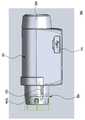
도 1 내지 도 4에 도시된 바와 같이, 본 발명의 바람직한 실시 예에 따른 주사량 측정 장치(100)는, 하우징(101), 회전 링(103), 엔코더, 보조 슬리브(102)를 구비하며, 약물 주입기(10; 도 13에 도시됨)에 착탈 가능하게 구성된다. 상기 약물 주입기(10)로는 인슐린 펜을 예로 들 수 있으며, 하기에서 본 발명의 구체적인 실시 예를 설명함에 있어, 상기 주사량 측정 장치(100)는 인슐린 펜에 착탈 가능한 구성으로 설명하기로 한다.1 to 4, a scanning
도시되지는 않지만, 상기 하우징(101)에는 데이터 저장용 메모리, 통신 회로, 위성 신호 수신기 및 이를 제어하는 처리 장치(processor)가 구성될 수 있다. 하기에서 설명되겠지만, 상기 엔코더는 상기 회전 링(103)의 회전량을 검출하며, 검출된 회전량으로부터 상기 처리 장치가 주사량을 산출하여 메모리에 저장하게 된다. 이때, 통신 회로 또는 위성 신호 수신기를 통해 주사 일시, 주사 위치 등의 정보를 수신하여 주사량과 함께 메모리에 저장될 수 있다. 상기 통신 회로는 근접 무선 통신(near field communication; NFC), 블루투스 등의 통신 규격에 맞게 제작될 수 있다. 이러한 통신 회로가 사용자의 이동통신 단말기 등과 접속 가능하게 구성된다면, 주사 시점에서, 주사 일시, 주입량, 온도/습도, 고도 및 기압, 질환 정보와 같은 환자의 프로필에 관한 정보를 수신할 수도 있을 것이다. 또한, 이동통신 단말기 자체에 위성 신호 수신기가 탑재되어 있다면, 상기 하우징(101)에 위성 신호 수신기가 탑재되지 않더라도 상기 주사량 측정 장치(100)는 이동통신 단말기를 통해 주사 위치에 관한 정보를 수신할 수 있을 것이다. 아울러, 사용자는 상기 주사량 측정 장치(100)가 장착될 약물 주입기의 약물 종류, 함량, 제조사 등의 정보를 메모리에 미리 입력해 둘 수도 있다. 이렇게, 기기 자체 또는 이동통신 단말기 등, 무선통신을 통하여 기록하거나 얻어진 정보는 상기 주사량 측정 장치(100)를 통해 기록, 저장되며, 이러한 주입 당시의 환경 정보 등으로부터 환자 및 약물의 상태 등을 예측하여, 차후 의사 진료 및 치료에 참고정보로써 활용될 수 있다.Although not shown, the
상기와 같이 주사 시점에서 기록되는 정보의 획득은 다양한 경로를 통해 이루어질 수 있다. 또한, 본 발명은 약물 주입기에 착탈 가능하게 제공되는 주사량 측정 장치를 제공하기 위한 것임을 고려하여, 주사 시점에 관련된 정보의 획득, 처리 및 저장에 관한 더 이상의 상세한 설명은 생략하기로 한다.As described above, the acquisition of the information recorded at the scanning time can be performed through various paths. Further, considering that the present invention is intended to provide a scanning dose measuring apparatus provided detachably to a drug injector, a further detailed description on acquiring, processing and storing information related to the scanning time will be omitted.
도 3을 참조하면, 상기 하우징(101)은, 일측단으로부터 길이 방향을 따라 관통하게 형성된 관통홀(113)을 구비하며, 상기 관통홀(113) 내에 상기 회전 링(103)과 보조 슬리브(102)가 수용된다. 상기 약물 주입기(10)는 길이 방향으로 상기 관통홀(113)에 삽입되어 상기 약물 주입기(10)의 본체(11)가 상기 하우징(101)에 고정되고, 상기 약물 주입기(10)의 다이얼 슬리브(21)는 상기 보조 슬리브(102)와 결속된다. 도시되지는 않지만, 상기 하우징(101)은 상면(101a)에 적어도 하나의 버튼과 디스플레이 장치를 구비할 수 있다. 상기 버튼은 주사 시점에서의 정보 입력, 저장된 정보의 출력 등을 실행하기 위한 것이며, 상기 디스플레이 장치를 통해 상기 버튼의 조작에 따른 명령의 실행 경과가 출력된다. 또한, 상기 하우징(101)은 데이터 포트(111)를 구비할 수 있다. 상기 주사량 측정 장치(100)는 상기 데이터 포트(111)에 연결되는 별도의 케이블 등을 통해 개인용 컴퓨터 등에 접속될 수 있다. 따라서 사용자나 담당 의사는 상기 주사량 측정 장치(100)에 저장된 정보 등을 추출할 수 있으며, 또한, 약물의 종류나 함량 등에 관한 정보를 상기 주사량 측정 장치(100)에 입력할 수도 있다.Referring to FIG. 3, the
상기 하우징(101)의 관통홀(113) 내에는 원주 방향을 따라 회전홈(115)이 형성되어 있다. 상기 회전홈(115)은 상기 하우징(101)의 타측단에 인접하게 위치되어 있으며, 상기 회전 링(103)을 회전 가능하게 수용하게 된다. 따라서 상기 회전 링(103)은 상기 하우징(101) 내에서, 더 나아가서는, 약물 주입기 상에서 회전할 수 있지만, 길이 방향에서는 고정된 상태를 유지하게 된다.In the through
아울러, 상기 하우징(101)에는, 상기 회전홈(115)에 인접하는 위치에서 상기 엔코더의 일부를 구성하는 회전 검출 소자(139)가 설치된다. 상기 회전 검출 소자(139)는 상기 회전 링(103)과 물리적으로 접촉하여 상기 회전 링(103)의 회전량을 검출하는 양방향 검출 스위치(2-way detection switch)나 광학 센서(optical sensor), 홀 센서(Hall effect sensor) 등으로 구성될 수 있다. 상기와 같은 엔코더의 구성은 하기에서 더 상세하게 설명될 것이다.In addition, the
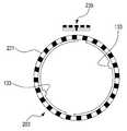
도 5는 상기 회전 링(103)을 도시하고 있다. 상기 회전 링(103)은 외주면에, 원주 방향을 따라 주기적으로 형성된 간섭 돌기(131)들을 구비한다. 아울러, 상기 회전 링(103)의 내주면에는 가이드 돌기(133)가 형성된다. 상기 가이드 돌기(133) 또한 복수로 형성될 수 있으며, 도 5에서는 한 쌍으로 형성된 구성이 도시되어 있다. 상기 회전 링(103)이 상기 회전홈(115)에 수용되면, 상기 간섭 돌기(131)들은 상기 회전홈(115)의 내벽에 마주보게 위치된다. 이때, 상기 회전 검출 소자(139)는, 도 6에 도시된 바와 같이, 양방향 검출 스위치로 구성된다. 상기 회전 링(103)이 회전함에 따라, 상기 양방향 검출 스위치가 상기 간섭 돌기(131)들과 순차적으로 간섭되면서 온/오프 동작을 반복하게 된다. 상기 양방향 검출 스위치의 온/오프 동작에 따라 상기 회전 링(103)의 회전량이 검출되고, 상기 주사량 측정 장치(100)는 상기 회전 링(103)의 회전량으로부터 사용자가 설정하는 약물의 주사량을 산출할 수 있게 된다.Fig. 5 shows the
한편, 도 7을 참조하면, 상기 회전 검출 소자(139)는 비접촉식 감지 센서(239), 예를 들면, 광학 센서나 홀 센서로 대체될 수 있음을 앞서 언급한 바 있다. 이 경우, 상기 회전 링(203)의 외주면에는 상기 비접촉식 감지 센서(239)에 대응되는 패턴(231)이 형성된다. 상기 비접촉식 감지 센서(239)가 광학 센서로 구성된다면, 상기 패턴(231)은 상기 회전 링(203)의 원주 방향을 따라 반사체와 비 반사체, 예를 들면, 흰색의 영역과 검은색의 영역이 번갈아 형성된 광학 패턴이 배치될 수 있다. 또한, 상기 비접촉식 감지 센서(239)가 홀 센서로 구성된다면, 상기 패턴(231)은 상기 회전 링(203)의 원주 방향을 따라 N극과 S극이 번갈아 형성된 자기 패턴으로 이루어질 수 있다. 광학 센서 또는 홀 센서와 같은 비접촉식 감지 센서(239)는 상기 회전 링(203)의 외주면에 구성된 광학 패턴 또는 자기 패턴의 변화를 검출하며, 이를 통해 상기 회전 링(203)의 회전량 및 회전 방향을 측정할 수 있게 된다.7, it is noted that the
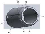
도 8은 상기 보조 슬리브(102)를 도시하고 있다. 상기 보조 슬리브(102)는 상기 하우징(101)에 수용되면서, 상기 하우징(101) 상에서 회전 가능함과 동시에 길이 방향으로 직선 운동이 가능하다. 상기 보조 슬리브(102)는 약물 주입기(10)의 다이얼 슬리브(21)에 결속된다. 즉, 상기 하우징(101)이 상기 약물 주입기(10)의 본체(11)에 고정되고, 상기 보조 슬리브(102)는 약물 주입기(10)의 다이얼 슬리브(21)에 고정되는 것이다. 상기 약물 주입기(10)의 다이얼 슬리브(21)는 본체(11)에 대하여 나선운동, 즉, 회전함에 따라 길이 방향으로 직선이동하게 된다. 따라서 상기 주사량 측정 장치(100)가 약물 주입기(10)에 장착된 상태에서, 상기 보조 슬리브(102) 또한 상기 하우징(101)에 대하여 나선운동하게 된다.Fig. 8 shows the
대체로, 약물 주입기(10)의 다이얼 슬리브(21) 외주면에는 돌기(25)나 홈을 형성하거나 마찰력이 큰 고무 재질로 다이얼 슬리브(21)의 외주면 일부분, 특히 조절 손잡이(23) 부분을 감싸게 된다. 이러한 돌기(25)나 홈 또는 고무 재질의 조절 손잡이(23)가 상기 보조 슬리브(102)의 내측면에 밀착, 고정됨으로써, 상기 보조 슬리브(102)는 약물 주입기(10)의 다이얼 슬리브(21)에 고정된다. 이러한 다이얼 슬리브(21)의 형상에 따라, 상기 보조 슬리브(102)의 내주면에는 결속홈(123)이 형성될 수 있다. 이때, 약물 주입기(10)의 다이얼 슬리브(21) 외주면에 형성된 돌기는 상기 결속홈(123)에 맞물리는 결속 돌기(25)로 활용될 수 있다. 다만, 다이얼 슬리브(21)의 조절 손잡이(23) 부분이 고무 재질로 감싸지면서 그 외주면에 돌기들이 형성된 경우, 돌기들 자체로서 상기 보조 슬리브(102)의 내주면에 밀착, 고정될 수 있다. 따라서 상기 보조 슬리브(102)의 내주면에 별도의 결속홈(123)을 형성하지 않더라도 상기 보조 슬리브(102)는 약물 주입기(10)의 다이얼 슬리브(21)에 결속, 고정될 수도 있을 것이다.The outer circumferential surface of the
상기 보조 슬리브(102)의 외주면에는 길이 방향으로 연장된 가이드 홈(121)이 형성된다. 상기 가이드 홈(121)은 상기 회전 링(103)의 가이드 돌기(133)를 수용한다. 상기 회전 링(103)은 상기 하우징(101) 내에서 회전만 가능하며, 상기 보조 슬리브(102)는 약물 주입기(10)의 다이얼 슬리브(21)와 함께 상기 하우징(101)에 대하여 나선운동하게 된다. 상기 가이드 돌기(133)가 상기 가이드 홈(121)에 맞물림에 따라, 상기 회전 링(103)은 상기 보조 슬리브(102)와 함께 회전하게 된다. 이로써, 상기 회전 링(103)의 회전량으로부터 다이얼 슬리브(21)의 직선 이동 거리, 나아가서는 다이얼 슬리브(21)의 조절에 따른 사용자가 설정한 약물 주사량을 산출할 수 있게 되는 것이다.A
한편, 상기 가이드 홈(121)은 일단이 개방단(121a)으로, 타단은 폐쇄단(121b)으로 이루어져 있다. 상기 보조 슬리브(102)가 상기 하우징(101)으로부터 이탈하는 방향으로 이동할 때, 상기 가이드 돌기(133)가 상기 가이드 홈(121)의 폐쇄단(121b)에 간섭된다. 따라서 상기 보조 슬리브(102)가 상기 하우징(101)으로부터 이탈하는 것은 불가능하다. 상기 보조 슬리브(102)가 상기 하우징(101)으로 잠입하는 방향으로 이동하여 한계 지점에 이르렀을 때는, 하기에서 설명되는 가이드 부재(104)에 간섭되어 상기 보조 슬리브(102)는 더 이상 이동할 수 없게 된다. 즉, 상기 보조 슬리브(102)는 상기 하우징(101) 상에서 일정한 구간 내에서만 길이 방향으로 이동할 수 있는 것이다.On the other hand, the
상기 가이드 부재(104)가 도 9와 도 10에 도시되어 있다. 상기 가이드 부재(104)는 상기 하우징(101)에 고정되어 약물 주입기(10)의 본체(11) 일부분을 감싸게 배치되면서 상기 보조 슬리브(102)의 회전 및 직선 이동을 지지, 안내하게 된다. 상기 가이드 부재(104)는 대체로 실린더 형상이지만 일부분은 개방되어 있다. 상기 가이드 부재(104)의 내주면에는 고정 돌기(143)들이 형성되어 있는데, 상기 고정 돌기(143)들은 약물 주입기(10) 본체(11)의 외주면에 맞물리게 된다. 약물 주입기(10)의 본체(11)에는 상기 고정 돌기(143)에 상응하는 홈이 형성될 수도 있다. 다만, 약물 주입기(10)의 본체(11) 자체에 장식 효과 등을 위해 형성된 홈에 상기 고정 돌기(143)가 맞물릴 수도 있다.The
약물 주입기(10)의 다이얼 슬리브(21)에 인쇄된 주사량 수치 등은 본체(11)에 형성되는 표시창(15)을 통해 사용자가 확인할 수 있다. 이러한 표시창(15)은 본체(11)의 일부분을 개방하거나, 개방된 부분에 투명 윈도우를 장착하여 구성된다. 이러한 표시창(15)의 가장자리에 상기 고정 돌기(143)가 결속될 수도 있다.The amount of the injected amount printed on the
상기 가이드 부재(104)는 결속 리브(141)를 구비할 수 있다. 상기 결속 리브(141)는 상기 가이드 부재(104)의 외주면으로부터 돌출된 형상으로서, 상기 하우징(101)의 내부에 고정된다. 이로써 상기 가이드 부재(104)가 상기 하우징(101)에 고정되며, 상기 보조 슬리브(102)의 이동 범위를 제한할 수 있게 된다. 상기 가이드 부재(104)의 일단에는 슬릿(147)들이 형성되어 상기 가이드 부재(104)의 일부분이 탄성편(145)으로 구성된다. 상기 탄성편(145)은 상기 가이드 부재(104)의 다른 부분에 대하여 일정 정도 변형 가능하게 된다. 상기 주사량 측정 장치(100)가 약물 주입기(10)에 장착된 상태에서, 상기 탄성편(145)은 약물 주입기(10)의 외주면에 밀착하여 상기 주사량 측정 장치(100)를 약물 주입기(10)에 고정하게 된다.The
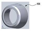
한편, 상기 하우징(101)은 2개의 부재를 마주보게 결합하여 완성될 수 있으며, 2개의 부재가 결합된 상태를 유지하기 위해 상기 주사량 측정 장치(100)는 고정 부재(105)를 더 구비할 수 있다. 상기 고정 부재(105)는 상기 하우징(101)의 일단에 회전 가능하게 결합된다. 도 11과 도 12를 참조하면, 상기 고정 부재(105)는 양단이 개방되어 있으며, 내주면에는 가이드 레일(153)이 형성된다. 상기 가이드 레일(153)은 상기 하우징(101) 상에 형성된 홈(미도시)에 맞물려 상기 고정 부재(105)의 회전을 안내하면서, 상기 고정 부재(105)가 상기 하우징(101)으로부터 이탈하는 것을 방지한다. 아울러, 상기 고정 부재(105)의 내주면에는 제1 가압 돌출부(151)와, 클릭 돌기(155)가 제공된다.Meanwhile, the
상기 제1 가압 돌출부(151)는 상기 고정 부재(105)의 내주면의 일부분이 돌출되어 형성된 것으로서, 상기 제1 가압 돌출부(151)가 형성된 부분에서 상기 고정 부재(105)의 회전 방향을 따라 상기 고정 부재(105)의 내부 지름이 점차 완만하게 증가 또는 감소하게 된다. 상기 고정 부재(105)가 상기 하우징(101)에 결합하면, 상기 제1 가압 돌출부(151)는 상기 가이드 부재(104)의 일단부 외주면, 더 구체적으로 상기 탄성편(145)의 외주면과 마주보게 위치된다.The first
이때, 도 10에 도시된 바와 같이, 상기 탄성편(145)의 외주면에는 제2의 가압 돌출부(149)가 형성될 수 있다. 상기 제2 가압 돌출부(149)가 형성된 부분에서, 상기 고정 부재(105)의 회전 방향을 따라 상기 가이드 부재(104)의 외부 지름이 점차 완만하게 증가 또는 감소하게 된다. 상기 고정 부재(105)가 회전하여 상기 제1, 제2 가압 돌출부(151, 149)가 서로 마주보는 위치(이하, '잠금 위치'라 함)에 있을 때, 상기 탄성편(145)이 상기 가이드 부재(104)의 내측으로 이동하게 된다. 상기 주사량 측정 장치(100)가 약물 주입기(10)에 장착된 상태라면, 잠금 위치에서 상기 탄성편(145)은 상기 가이드 부재(104)의 내측으로 이동하면서, 약물 주입기(10) 본체(11)의 외주면에 밀착, 고정된다. 즉, 상기 고정 부재(105)의 회전에 따라 상기 가이드 부재(104), 나아가서는 상기 주사량 측정 장치(100)가 약물 주입기(10)에 완전히 고정될 수 있는 것이다.At this time, as shown in FIG. 10, a second
상기 클릭 돌기(155)는 상기 고정 부재(105)의 내주면에서 탄성 지지된 구조로서, 상기 고정 부재(105)가 회전하면 상기 하우징(101)의 외주면에 미끄럼 접촉하게 된다. 도시되지는 않지만, 상기 하우징(101)의 외주면에서 상기 클릭 돌기(155)가 이동하는 궤적 상에 상기 클릭 돌기(155)가 맞물릴 수 있는 클릭 홈(미도시)들이 형성될 수 있다. 상기 잠금 위치에서, 상기 클릭 돌기(155)는 클릭 홈들 중 하나와 맞물리는 것이 바람직하다.The
앞서 언급한 바와 같이, 상기 제1, 제2 가압 돌출부(151, 149) 자체는 상기 고정 부재(105)의 회전 방향에서, 점차 그 두께가 증가하거나 감소하게 된다. 상기와 같은 탄성편(145)과 제1, 제2 가압 돌출부(151, 149)의 구성에 의해 상기 고정 부재(105)는 상기 잠금 위치에서 벗어나는 방향으로 회전하려는 성향을 가지게 된다. 이러한 고정 부재(105)의 회전 성향은, 상기 주사량 측정 장치(100)가 약물 주입기(10)에 장착된 상태에서 더 커지게 될 것이다. 따라서 상기 잠금 위치에서 상기 클릭 돌기(155)가 상기 하우징(101) 상에 형성된 클릭 홈에 맞물린다면, 상기 고정 부재(105)의 회전을 억제할 수 있다. 만약, 상기 제1, 제2 가압 돌출부(151, 149), 탄성편(145)의 구성에 의해 상기 고정 부재(105)가 회전하여 상기 잠금 위치로부터 벗어나게 된다면, 상기 주사량 측정 장치(100)는 약물 주입기(10)에 안정적으로 고정되지 못하게 될 것이다. 또한, 약물 주입기나, 약물 카트리지를 교체할 때, 사용자는 상기 고정 부재(105)를 회전시키는 것만으로 잠금 상태를 해제할 수 있으므로 상기 주사량 측정 장치(100)를 약물 주입기로부터 용이하게 분리할 수 있다.As described above, the first and second
도 13은 상기 주사량 측정 장치(100)가 장착되는 약물 주입기(10)를 도시하고, 도 14와 도 15는 각각 상기 약물 주입기(10)에 상기 주사량 측정 장치(100)가 결합된 모습을 도시하고 있다.13 shows a
앞서 언급한 바와 같이, 상기 약물 주입기(10)는 길이 방향으로 연장된 실린더 형상의 본체(11)와 상기 본체(11)에 나선운동 가능하게 결합된 다이얼 슬리브(21)를 구비한다. 상기 본체(11)의 일부분이 개방되어 표시창(15)이 형성되며, 상기 표시창(15) 주위에 장식 효과 등을 위한 홈(13)이 형성되어 있다. 앞서 언급한 바와 같이, 상기 가이드 부재(104)에 형성되는 고정 돌기(143)는 상기 표시창(15) 가장자리 또는 홈(13)에 맞물리게 구성될 수 있다. 한편, 상기 가이드 부재(104)는 상기 본체(11)의 일부분을 감싸게 제공되지만, 적어도 상기 표시창(15)은 노출시키는 것이 바람직하다. 이는 사용자가 주사량을 조절할 때, 상기 표시창(15)을 통해 상기 다이얼 슬리브(21)의 회전에 따른 주사량을 확인할 수 있게 하기 위함이다.As described above, the
상기 다이얼 슬리브(21)의 단부에는 조절 손잡이(23)가 제공되며, 상기 조절 손잡이(23)의 외주면에 결속 돌기(25)들이 형성되어 있다. 앞서 언급한 바와 같이, 상기 조절 손잡이(23)의 외주면은 고무 재질로 둘러싸일 수 있으며, 실질적으로 상기 조절 손잡이(23)의 외주면이 상기 보조 슬리브(102)의 내주면에 밀착, 고정된다. 또한, 상기 다이얼 슬리브(21)의 단부에는 주입 버튼(27)이 제공된다. 사용자는 상기 조절 손잡이를 이용해 상기 다이얼 슬리브(21)를 회전시켜 약물의 주사량을 조절하며, 선택된 주사량에 해당하는 만큼 상기 다이얼 슬리브(21)를 회전시킨 후 상기 주입 버튼(27)을 눌러 상기 약물 주입기(10)를 작동시키게 된다.At the end of the
한편, 상기 보조 슬리브(102)는 투명한 재질로 제작됨이 바람직하다. 앞서 언급한 바와 같이, 주사량을 조절하기 위해, 사용자가 상기 표시창(15)을 통해 확인을 하게 되는데, 이때, 상기 보조 슬리브(102)는 상기 본체(11)를 둘러싸면서 상기 하우징(101)에 결합되어 있다. 따라서 상기 보조 슬리브(102)가 투명한 재질로 제작됨으로써, 사용자는 상기 표시창(15)을 통해 조절된 주사량을 확인할 수 있다. 다만, 상기 회전 링(103)의 회전량으로부터 주사량의 산출이 가능하므로, 상기 주사량 측정 장치(100)의 디스플레이 장치에 조절된 주사량이 표시되도록 설정될 수 있다. 따라서 제품에 따라서는 상기 주사량 측정 장치(100)가 상기 약물 주입기(10)에 결합한 상태에서 상기 표시창(15)이 은폐될 수도 있을 것이다.Meanwhile, the
상기 약물 주입기(10)는 상기 하우징(101)의 일측에서, 길이 방향으로 상기 하우징(101), 구체적으로 상기 관통홀(113)에 삽입된다. 상기 약물 주입기(10)가 상기 하우징(101)에 완전히 삽입되면, 상기 다이얼 슬리브(21)의 조절 손잡이(23)가 부분적으로 상기 보조 슬리브(102)의 내주면에 결속되고, 부분적으로는 상기 보조 슬리브(102)의 단부로 돌출된다. 따라서 상기 주입 버튼(27)은 상기 보조 슬리브(102)의 단부에 노출된다. 이때, 상기 결속 돌기(25)들은 상기 보조 슬리브(102)의 내측면 밀착, 고정되거나 또는 상기 결속홈(123)에 맞물려 고정될 수 있다. 이로써, 상기 보조 슬리브(102)는 상기 다이얼 슬리브(21)와 함께 상기 본체(11)에 대하여 나선운동하게 된다.The
상기 약물 주입기(10)가 상기 하우징(101)에 완전히 삽입된 상태에서, 상기 고정 돌기(143)가 상기 본체(11)의 외주면, 예를 들면, 상기 표시창(15)의 가장자리에 맞물려 상기 가이드 부재(104)가 상기 본체(11)에 고정된다. 또한, 상기 고정 부재(105)가 잠금 위치로 회전하면, 상기 탄성편(145)이 상기 본체(11)의 외주면을 가압하면서 밀착, 고정된다. 이때, 한 쌍의 상기 탄성편(145)이 서로 마주보게 형성되어 있다면, 상기 가이드 부재(104)는 상기 본체(11)에 더 견고하게 고정될 것이다. 잠금 위치에서, 상기 고정 부재(105)의 클릭 돌기(155)가 상기 하우징(101)에 형성된 클릭 홈과 맞물림으로써, 상기 고정 부재(105)는 상기 하우징(101)에 고정된 상태를 안정적으로 유지하게 된다. 물론, 사용자가 상기 고정 부재(105)를 강제로 회전시킬 경우, 상기 클릭 돌기(155)는 클릭 홈으로부터 이탈하게 된다.The fixing
도 14와 도 15는 각각 상기 다이얼 슬리브(21)가 상기 본체(11)에 완전히 잠입한 상태를 도시하고 있고, 도 13은 상기 다이얼 슬리브(21)가 회전하여 상기 본체(11)로부터 인출된 상태를 도시하고 있다. 상기 다이얼 슬리브(21)가 상기 본체(11)에 완전히 잠입한 상태에서 사용자가 상기 조절 손잡이(23) 또는 보조 슬리브(102)를 회전시키면, 상기 다이얼 슬리브(21)가 나선운동하여 상기 본체(11)로부터 점차 인출된다. 상기 다이얼 슬리브(21)의 나선운동에 따라 상기 보조 슬리브(102) 또한 나선운동하게 된다. 따라서 상기 보조 슬리브(102)도 상기 하우징(101)으로부터 점차 인출된다.Figs. 14 and 15 show a state in which the
앞서 언급한 바와 같이, 상기 회전 링(103)은 상기 가이드 돌기(133)와 가이드 홈(121)의 구성에 의해 상기 보조 슬리브(102)와 함께 회전 가능하고, 길이 방향에서는 상기 하우징(101) 상에 고정되어 있다. 따라서 상기 보조 슬리브(102)의 나선운동에 따라 상기 회전 링(103)도 상기 하우징(101) 내에서 회전하게 된다. 상기 회전 링(103)의 외주면에 제공되는 간섭 돌기(131)들의 배열, 광학 패턴 또는 자기 패턴과, 그에 상응하는 상기 회전 검출 소자(139) 또는 비접촉식 감지 센서(239)의 조합으로 이루어지는 엔코더는 상기 회전 링(103)의 회전량을 검출하게 된다. 이로써, 상기 보조 슬리브(102)와 다이얼 슬리브(21)의 직선 이동 거리, 나아가서는 조절된 주사량을 산출할 수 있게 되는 것이다.The
한편, 상기 약물 주입기(10)로부터 상기 주사량 측정 장치(100)를 분리하고자 할 때, 사용자는 상기 고정 부재(105)를 잠금 위치로부터 이탈하게 회전시키게 된다. 상기 고정 부재(105)가 잠금 위치로부터 이탈하면, 상기 하우징(101)으로 삽입된 방향의 상기 약물 주입기(10)를 강제 이동시키면, 상기 약물 주입기(10)와 상기 주사량 측정 장치(100)가 용이하게 분리된다.
Meanwhile, when the
이상, 본 발명의 상세한 설명에서는 구체적인 실시 예에 관해서 설명하였으나, 본 발명의 범위에서 벗어나지 않는 한도 내에서 여러 가지 변형이 가능함은 당해 분야에서 통상의 지식을 가진 자에게 있어서 자명하다 할 것이다.While the present invention has been particularly shown and described with reference to exemplary embodiments thereof, it is to be understood that the invention is not limited to the disclosed exemplary embodiments.
100: 주사량 측정 장치 101: 하우징
102: 보조 슬리브 103: 회전링
104: 가이드 부재100: Injection measuring device 101: Housing
102: auxiliary sleeve 103: rotating ring
104: Guide member
Claims (15)
Translated fromKorean상기 본체에 착탈 가능하게 제공된 하우징;
상기 하우징 내에서 회전 가능하게 수용된 회전 링;
상기 하우징 내에 설치되어 상기 회전 링의 회전량을 검출하는 엔코더; 및
상기 다이얼 슬리브에 착탈 가능하게 제공되면서 상기 하우징 내에서 상기 다이얼 슬리브와 함께 나선 운동하는 보조 슬리브를 구비하고,
상기 회전 링은 상기 보조 슬리브에 결속되어 상기 보조 슬리브와 함께 회전하면서 상기 본체의 길이 방향에서는 상기 하우징 내에 고정됨을 특징으로 하는 주사량 측정 장치.
An injection amount measurement device for a drug injector, comprising: a body; and a dial sleeve spirally coupled to the body,
A housing detachably provided in the main body;
A rotating ring rotatably received in the housing;
An encoder installed in the housing and detecting an amount of rotation of the rotary ring; And
And an auxiliary sleeve detachably provided in the dial sleeve and helically moving together with the dial sleeve in the housing,
Wherein the rotation ring is coupled to the auxiliary sleeve and rotates together with the auxiliary sleeve, and is fixed in the housing in the longitudinal direction of the main body.
The medical instrument according to claim 1, wherein the drug injector is inserted into the housing in the longitudinal direction of the body at one side of the housing, whereby the dial sleeve end is bound to the inside of the auxiliary sleeve and the housing is bound on the body Characterized in that the injection quantity measuring device.
상기 다이얼 슬리브의 외주면에 형성되는 결속 돌기를 더 구비하고,
상기 결속 돌기가 상기 보조 슬리브의 내측면에 맞물림으로써, 상기 보조 슬리브는 상기 다이얼 슬리브와 함께 나선 운동함을 특징으로 하는 주사량 측정 장치.
3. The method according to claim 1 or 2,
And a coupling protrusion formed on an outer circumferential surface of the dial sleeve,
Wherein the coupling sleeve engages the inner surface of the auxiliary sleeve such that the auxiliary sleeve spirals together with the dial sleeve.
원주방향을 따라 상기 회전 링의 외주면에 주기적으로 형성된 간섭 돌기들; 및
상기 하우징에 설치되는 양방향 검출 스위치(2-way detection switch)를 구비하고,
상기 회전 링이 회전함에 따라 상기 양방향 검출 스위치가 상기 간섭 돌기들과 간섭됨에 따라 온/오프(on/off) 동작을 반복함을 특징으로 하는 주사량 측정 장치.
2. The encoder according to claim 1,
Interference protrusions periodically formed on an outer circumferential surface of the rotary ring along a circumferential direction; And
And a 2-way detection switch installed in the housing,
And the on / off operation is repeated as the bidirectional detection switch interferes with the interference protrusions as the rotary ring rotates.
원주방향을 따라 상기 회전 링의 외주면에 주기적으로 형성된 자기 패턴(magnetic pattern); 및
상기 하우징에 설치되는 홀 센서(Hall effect sensor)를 구비하고,
상기 회전 링이 회전함에 따라 상기 홀 센서가 상기 자기 패턴의 변화를 검출함을 특징으로 하는 주사량 측정 장치.
2. The encoder according to claim 1,
A magnetic pattern periodically formed on an outer peripheral surface of the rotary ring along a circumferential direction; And
And a Hall effect sensor installed in the housing,
And the hall sensor detects a change in the magnetic pattern as the rotary ring rotates.
원주방향을 따라 상기 회전 링의 외주면에 주기적으로 형성된 광학 패턴(optical pattern); 및
상기 하우징에 설치되는 광학 센서(optical sensor)를 구비하고,
상기 회전 링이 회전함에 따라 상기 광학 센서가 상기 광학 패턴의 변화를 검출함을 특징으로 하는 주사량 측정 장치.
2. The encoder according to claim 1,
An optical pattern periodically formed on an outer circumferential surface of the rotary ring along a circumferential direction; And
And an optical sensor provided in the housing,
And the optical sensor detects a change in the optical pattern as the rotating ring rotates.
상기 보조 슬리브의 외주면에서 길이 방향으로 연장된 적어도 하나의 가이드 홈; 및
상기 회전 링의 내주면에 형성되어 상기 가이드 홈에 맞물리는 가이드 돌기를 더 구비하고,
상기 가이드 돌기가 상기 가이드 홈에 맞물림으로써, 상기 회전 링은 상기 보조 슬리브와 함께 회전하면서 상기 본체의 길이 방향에서는 상기 하우징 내에 고정됨을 특징으로 하는 주사량 측정 장치.
The method according to claim 1,
At least one guide groove extending in the longitudinal direction on an outer circumferential surface of the auxiliary sleeve; And
Further comprising a guide projection formed on an inner circumferential surface of the rotary ring and engaged with the guide groove,
Wherein the guide projection is engaged with the guide groove so that the rotation ring rotates together with the auxiliary sleeve and is fixed in the housing in the longitudinal direction of the body.
[8] The apparatus according to claim 7, wherein one end of the guide groove is an open end and the other end is a closed end.
적어도 일부분이 상기 하우징의 내부에 수용되면서 상기 본체의 외주면에 고정되는 가이드 부재를 더 구비하고,
상기 가이드 부재는 상기 본체의 길이 방향으로 연장되어 상기 보조 슬리브의 나선 운동을 안내함을 특징으로 하는 주사량 측정 장치.
The method according to claim 1,
Further comprising a guide member fixed at an outer circumferential surface of the main body while at least a portion thereof is accommodated in the housing,
Wherein the guide member extends in the longitudinal direction of the main body to guide the helical motion of the auxiliary sleeve.
10. The apparatus according to claim 9, wherein the guide member has an elastic piece which is in close contact with an outer peripheral surface of the main body.
상기 본체의 외주면 상에서 상기 하우징의 일단에 회전 가능하게 결합하는 고정 부재; 및
상기 가이드 부재의 일단에 형성되면서 상기 고정 부재에 둘러싸이는 탄성편을 더 구비하고,
상기 고정 부재가 상기 탄성편을 가압하여 상기 본체의 외주면에 밀착시킴을 특징으로 하는 주사량 측정 장치.
10. The method of claim 9,
A fixing member rotatably coupled to one end of the housing on an outer peripheral surface of the main body; And
Further comprising an elastic piece formed on one end of the guide member and surrounded by the fixing member,
Wherein the fixing member presses the elastic piece to adhere to the outer peripheral surface of the main body.
상기 고정 부재의 내주면에 형성되는 제1 가압 돌출부; 및
상기 탄성편의 외주면에 형성되는 제2 가압 돌출부를 더 구비하고,
상기 고정 부재가 회전함에 따라, 상기 제1 가압 돌출부가 상기 제2 가압 돌출부와 마주하는 위치에서 상기 탄성편이 상기 본체의 외주면에 밀착됨을 특징으로 하는 주사량 측정 장치.
12. The method of claim 11,
A first pressing protrusion formed on an inner circumferential surface of the fixing member; And
Further comprising a second pressing protrusion formed on an outer circumferential surface of the elastic piece,
Wherein the elastic piece is in close contact with the outer circumferential surface of the main body at a position where the first pressing protrusion faces the second pressing protrusion as the fixing member rotates.
상기 가이드 부재의 내주면에 형성되는 고정 돌기를 더 구비하고,
상기 고정 돌기가 상기 본체의 외주면 상에 맞물림으로써 상기 가이드 부재가 상기 본체에 고정됨을 특징으로 하는 주사량 측정 장치.
10. The method of claim 9,
And a fixing protrusion formed on an inner circumferential surface of the guide member,
And the guide member is fixed to the main body by engaging the fixing protrusion on the outer peripheral surface of the main body.
상기 하우징의 내주면에서 원주 방향을 따라 형성되어 상기 회전 링을 회전 가능하게 수용하는 회전홈을 더 구비함을 특징으로 하는 주사량 측정 장치.
The method according to claim 1,
Further comprising a rotation groove formed in the inner circumferential surface of the housing in the circumferential direction to rotatably receive the rotation ring.
Priority Applications (2)
| Application Number | Priority Date | Filing Date | Title |
|---|---|---|---|
| KR1020130002760AKR20140090763A (en) | 2013-01-10 | 2013-01-10 | Measuring device for measuring dose in drug delivery device |
| US14/151,204US20140194829A1 (en) | 2013-01-10 | 2014-01-09 | Dose measuring device for drug delivery device |
Applications Claiming Priority (1)
| Application Number | Priority Date | Filing Date | Title |
|---|---|---|---|
| KR1020130002760AKR20140090763A (en) | 2013-01-10 | 2013-01-10 | Measuring device for measuring dose in drug delivery device |
Publications (1)
| Publication Number | Publication Date |
|---|---|
| KR20140090763Atrue KR20140090763A (en) | 2014-07-18 |
Family
ID=51061527
Family Applications (1)
| Application Number | Title | Priority Date | Filing Date |
|---|---|---|---|
| KR1020130002760AWithdrawnKR20140090763A (en) | 2013-01-10 | 2013-01-10 | Measuring device for measuring dose in drug delivery device |
Country Status (2)
| Country | Link |
|---|---|
| US (1) | US20140194829A1 (en) |
| KR (1) | KR20140090763A (en) |
Cited By (5)
| Publication number | Priority date | Publication date | Assignee | Title |
|---|---|---|---|---|
| WO2019009638A1 (en)* | 2017-07-07 | 2019-01-10 | 최규동 | General-purpose mounting-type input amount measurement and management system of pen type syringe device |
| KR20200025378A (en)* | 2018-08-30 | 2020-03-10 | 주식회사 아모라이프사이언스 | Drug injection pen manager |
| KR20230108851A (en)* | 2022-01-12 | 2023-07-19 | 주식회사 피에이치씨 | Medicine injection system |
| KR20230114520A (en)* | 2022-01-25 | 2023-08-01 | 주식회사 피에이치씨 | Medicine injection system |
| WO2024154987A1 (en)* | 2023-01-20 | 2024-07-25 | 투바이오스 주식회사 | Pushing device for drug delivery device |
Families Citing this family (25)
| Publication number | Priority date | Publication date | Assignee | Title |
|---|---|---|---|---|
| WO2012127046A2 (en) | 2011-03-24 | 2012-09-27 | Sanofi-Aventis Deutschland Gmbh | Device and method for detecting an actuation action performable with a medical device |
| WO2014118111A1 (en)* | 2013-01-29 | 2014-08-07 | Sanofi-Aventis Deutschland Gmbh | Electronic module and drug delivery device |
| US10420897B2 (en)* | 2013-05-07 | 2019-09-24 | Sanofi-Aventis Deutschland Gmbh | Supplemental device for attachment to an injection device |
| CN106573115B (en)* | 2014-08-25 | 2019-12-24 | 诺和诺德股份有限公司 | Attachment with snap-fit feature |
| EP3058970A1 (en) | 2015-02-19 | 2016-08-24 | Sanofi-Aventis Deutschland GmbH | Data collection device for attachment to an injection device |
| EP3132821B1 (en)* | 2015-03-03 | 2018-12-19 | Innovative Precision Instruments Limited | Drug information detection apparatus and drug information detection type injection apparatus |
| CN113456946B (en) | 2015-06-09 | 2023-12-26 | 赛诺菲-安万特德国有限公司 | Data acquisition device for attachment to an injection device |
| EP3175876A1 (en)* | 2015-12-01 | 2017-06-07 | Carebay Europe Ltd. | Medicament delivery device with user feedback capability |
| WO2017096510A1 (en)* | 2015-12-07 | 2017-06-15 | 创新精密仪器有限公司 | Injection dosage detection device and injection apparatus comprising same |
| US10857304B2 (en) | 2016-03-25 | 2020-12-08 | Eli Lilly And Company | Determination of a dose set and delivered in a medication delivery device |
| WO2017184401A1 (en) | 2016-04-19 | 2017-10-26 | Eli Lilly And Company | Determination of a dose in a medication delivery device using two moving arrays with teeth and a sensor |
| EP3448470B1 (en)* | 2016-04-29 | 2020-03-18 | Novo Nordisk A/S | Drug delivery system with dose capturing |
| PT3484547T (en) | 2016-07-15 | 2022-05-19 | Lilly Co Eli | Dose detection module for a medication delivery device |
| US9636464B1 (en)* | 2016-08-01 | 2017-05-02 | Innovative Precision Instruments Limited | Drug delivery device and a drug information detection device |
| CA3033232C (en) | 2016-08-12 | 2022-09-06 | Eli Lilly And Company | Dose sensing mechanism in a medication delivery device |
| WO2018111708A1 (en) | 2016-12-15 | 2018-06-21 | Eli Lilly And Company | Medication delivery device with sensing system |
| CA3050752C (en) | 2017-02-28 | 2022-09-06 | Eli Lilly And Company | Dose detection and drug identification for a medication delivery device |
| ES2985951T3 (en) | 2017-08-18 | 2024-11-07 | Lilly Co Eli | Dosing measurement module on injection pen |
| CN115252969B (en) | 2017-08-21 | 2024-10-15 | 伊莱利利公司 | Dose detection module for a drug delivery device |
| CA3073605C (en) | 2017-08-21 | 2023-03-21 | Eli Lilly And Company | Medication delivery device with sensing system |
| ES2996276T3 (en) | 2017-08-21 | 2025-02-12 | Lilly Co Eli | Dose detection module for a medication delivery device |
| US12329945B2 (en)* | 2017-12-18 | 2025-06-17 | Sanofi | Dose recording device |
| US11071831B2 (en) | 2018-02-22 | 2021-07-27 | Eli Lilly And Company | Dose detection system module for medication delivery device |
| MX2021009853A (en) | 2019-02-27 | 2021-09-10 | Lilly Co Eli | Medication delivery device with sensing system. |
| US20230355882A1 (en)* | 2020-08-26 | 2023-11-09 | Eli Lilly And Company | Medication delivery device with sensing system |
- 2013
- 2013-01-10KRKR1020130002760Apatent/KR20140090763A/ennot_activeWithdrawn
- 2014
- 2014-01-09USUS14/151,204patent/US20140194829A1/ennot_activeAbandoned
Cited By (5)
| Publication number | Priority date | Publication date | Assignee | Title |
|---|---|---|---|---|
| WO2019009638A1 (en)* | 2017-07-07 | 2019-01-10 | 최규동 | General-purpose mounting-type input amount measurement and management system of pen type syringe device |
| KR20200025378A (en)* | 2018-08-30 | 2020-03-10 | 주식회사 아모라이프사이언스 | Drug injection pen manager |
| KR20230108851A (en)* | 2022-01-12 | 2023-07-19 | 주식회사 피에이치씨 | Medicine injection system |
| KR20230114520A (en)* | 2022-01-25 | 2023-08-01 | 주식회사 피에이치씨 | Medicine injection system |
| WO2024154987A1 (en)* | 2023-01-20 | 2024-07-25 | 투바이오스 주식회사 | Pushing device for drug delivery device |
Also Published As
| Publication number | Publication date |
|---|---|
| US20140194829A1 (en) | 2014-07-10 |
Similar Documents
| Publication | Publication Date | Title |
|---|---|---|
| KR20140090763A (en) | Measuring device for measuring dose in drug delivery device | |
| JP6928058B2 (en) | Sensor device that can be attached to and detached from the drug delivery device | |
| CA2324915C (en) | Electronic medical delivery pen having a multifunction actuator | |
| AU2020261314B2 (en) | Injection monitoring module | |
| CN110997044B (en) | Dose detection module for a drug delivery device | |
| JP5711155B2 (en) | Medical module for drug delivery pen | |
| JP6510495B2 (en) | Supplemental device for attachment to an injection device | |
| JP4480330B2 (en) | Improvements to and related to infusion devices | |
| US20080188813A1 (en) | Injection Device with a Processor for Collecting Ejection Information | |
| JP2024020586A (en) | Treatment devices, methods, and systems including piston-based detectors | |
| EP2060288A1 (en) | Administration device having input unit | |
| CN211094134U (en) | Cover for a dosing device | |
| CN109152886A (en) | Fluid discharging apparatus is used to the method for the fluid discharging apparatus of exhaust fluid and for the method for its operation for manufacturing | |
| HK40017415A (en) | Therapy devices, methods, and systems including a piston-style detector | |
| HK40014957A (en) | Sensor device removably attachable to a drug delivery device | |
| HK1232944A1 (en) | Sensor device removably attachable to a drug delivery device | |
| HK1232944B (en) | Sensor device removably attachable to a drug delivery device | |
| HK40018319A (en) | Medical module for drug delivery pen | |
| HK40018318A (en) | Medical module for drug delivery pen |
Legal Events
| Date | Code | Title | Description |
|---|---|---|---|
| PA0109 | Patent application | Patent event code:PA01091R01D Comment text:Patent Application Patent event date:20130110 | |
| PG1501 | Laying open of application | ||
| PC1203 | Withdrawal of no request for examination | ||
| WITN | Application deemed withdrawn, e.g. because no request for examination was filed or no examination fee was paid |